TENDER DOCUMENT FOR GEO-TECHNICAL INVESTIGATION WORK · PDF fileTENDER FOR GEO-TECHNICAL...
24
TENDER FOR GEO-TECHNICAL INVESTIGATION WORK PC107-PNCV-TD-202 0 DOCUMENT. NO. REV. SHEET 0 OF 29 _________________________________________________________________________________________________ FORM NUMBER 02-0000-0021 F1 REV 0 All rights reserved (Annex.-VI) TENDER DOCUMENT FOR GEO-TECHNICAL INVESTIGATION WORK FOR FAGMIL GRANULATED SINGLE SUPER PHOSPHATE PLANT AT CHITTORGARH, RAJASTHAN
Transcript of TENDER DOCUMENT FOR GEO-TECHNICAL INVESTIGATION WORK · PDF fileTENDER FOR GEO-TECHNICAL...
TENDER FOR GEO-TECHNICAL INVESTIGATION WORK
PC107-PNCV-TD-202 0 DOCUMENT. NO. REV. SHEET 0 OF 29
_________________________________________________________________________________________________ FORM NUMBER 02-0000-0021 F1 REV 0 All rights reserved
(Annex.-VI)
TENDER DOCUMENT FOR
GEO-TECHNICAL INVESTIGATION WORK FOR
FAGMIL GRANULATED SINGLE SUPER PHOSPHATE PLANT
AT CHITTORGARH, RAJASTHAN
TECHNICAL SPECIFICATIONS FOR GEO-TECHNICAL INVESTIGATION WORK
PC107-PNCV-TS-202 0 DOCUMENT. NO. REV. SHEET 1 OF 16
_________________________________________________________________________________________________ FORM NUMBER 02-0000-0021 F1 REV 0 All rights reserved
TECHNICAL SPECIFICATIONS FOR
GEO-TECHNICAL INVESTIGATION WORK FOR
FAGMIL GRANULATED SINGLE SUPER PHOSPHATE PLANT
AT CHITTORGARH, RAJASTHAN
0 11.04.16 ISSUED FOR TENDER GC GC BRIJESH
REV DATE PURPOSE PREPARED REVIEWED APPROVED
TECHNICAL SPECIFICATIONS FOR GEO-TECHNICAL INVESTIGATION WORK
PC107-PNCV- TS-202 0 DOCUMENT. NO. REV. SHEET 2 OF 16
_________________________________________________________________________________________________ FORM NUMBER 02-0000-0021 F1 REV 0 All rights reserved
CONTENTS
1.0 GENERAL ..................................................................................................................... 3
2.0 SCOPE OF WORK........................................................................................................ 3
2.1 DESCRIPTION OF WORK ......................................................................................... 3
2.2 SCOPE ...................................................................................................................... 3
3. 0 CODES ...................................................................................................................... 4
4.0 FIELD INVESTIGATIONS – SOIL ................................................................................ 5
4.1 BORING ..................................................................................................................... 5
4.2 IN-SITU TESTING ...................................................................................................... 7
4.3 SAMPLING ............................................................................................................... 11
5.0 LABORATORY TESTING OF SOILS ......................................................................... 13
5.1 STORING OF SOIL SAMPLES IN LABORATORY .................................................. 13
5.2 HANDLING OF UNDISTURBED SAMPLES IN LABORATORY .............................. 13
5. 3 PROCEDURES OF TESTING ................................................................................. 14
6.0 REPORT .................................................................................................................. 14

TECHNICAL SPECIFICATIONS FOR GEO-TECHNICAL INVESTIGATION WORK
PC107-PNCV- TS-202 0 DOCUMENT. NO. REV. SHEET 3 OF 16
_________________________________________________________________________________________________ FORM NUMBER 02-0000-0021 F1 REV 0 All rights reserved
1.0 GENERAL
1.1 The Project proponent, FCI Aravali Gypsum & Minerals India Ltd (FAGMIL) is proposing to set up a Granulated Single Super Phosphate (GSSP) unit for production of 800 TPD or 2, 40,000 MTPA with required utilities & off-sites facilities at FAGMIL, Chittorgarh in the state of Rajasthan. The proposed Project site is located at village of Pandoli in Chittorgarh district of Rajasthan, adjacent to State Highway, SH-9, at a distance of 6 kms from Chittorgarh City.
1.2 The intent of this specification is to cover the basic requirements for conducting the Geo-technical investigations to generate requisite Soil information’s for the design of foundation and engineering activities and to provide the designer with sufficiently accurate information both general and specific about the substrata profile and relevant soil and rock parameters of the proposed site.
1.3 The work shall be executed as per specifications to fulfill the objectives of the Geo-technical investigations work, strictly in accordance with the direction of the Engineer-in-Charge at site.
1.4 This specification shall be read in conjunction with the description of items in the Schedule of Rates. The contractor shall refer to the Client / Consultant any discrepancy which may exist between the drawings, specifications and corresponding items of Schedule of Rates for clarification before submission of quotation and the Clients / Consultants decision as to clarification of the points raised shall be final binding to the Contractor.
2.0 SCOPE OF WORK
2.1 DESCRIPTION OF WORK 2.1.1 The M/s FAGMIL desires that detailed Geotechnical investigation survey is carried out to
provide the designer with sufficiently accurate information both general and specific about the substrata profile and relevant soil and rock parameters at site on the basis of which the foundations for various structures and equipment of the plants can be designed rationally.
2.1.2 The purpose of site investigation is to provide geotechnical information for proposed plant and verification of the drawings and other data related to the existing plant. Respective reports and findings will be used for layout and design of systems, structures and foundations for the proposed plant. The Bidder shall also prepare appropriate calculations and reports and submit them to Employer for approval.
2.2 SCOPE 2.2.1 This specification covers the technical requirements for detailed Geotechnical investigation
and submission of a detailed Geotechnical report. The work shall include mobilization of all necessary equipment, providing necessary engineering supervision and technical personnel, skilled and unskilled labors, etc. as required to carry out entire field work as well as laboratory investigation, analysis and interpretation of data collected & preparation of a Geotechnical report including recommendations regarding foundation level, type of

TECHNICAL SPECIFICATIONS FOR GEO-TECHNICAL INVESTIGATION WORK
PC107-PNCV- TS-202 0 DOCUMENT. NO. REV. SHEET 4 OF 16
_________________________________________________________________________________________________ FORM NUMBER 02-0000-0021 F1 REV 0 All rights reserved
foundation, land improvement and deep excavation as per requirements. The entire field work and laboratory work shall be supervised by a qualified geotechnical engineer.
2.2.2 The work to be performed under Scope of Work also consist of supplying & providing of all labour, material except if indicated in Schedule of Rates, supervision, scaffolding, construction equipments, tools, tackles and plants, supplies & transportation of all incidental items though not indicated or specified, but reasonably implied or necessary for successful completion of the work including Specifications” and Schedule of Rates” of this Tender including sampling and testing on item Rate basis. The Tender Drawings attached with these specifications provides a general ideal about the work to be performed under the scope of this Contract. The enclosed Drawings are preliminary Drawings which are for bidding purposes only and are by no means the final Drawings or show the full range of the work under the scope.
2.2.3 The Bidder shall make his own arrangements for locating the coordinates and positions of bore holes, trial pits, static cone penetration tests and other field tests as per the drawings/sketches supplied to him and for determining the elevations at these locations with respect to the bench marks. The Bidder has to provide at the site all the required survey instruments to the satisfaction of the Engineer so that the work can be carried out accurately according to specifications and drawings.
2.2.4 The work shall be carried out in accordance with the specification set out below and as directed by the Engineer-in-Charge, where necessary.
3. 0 CODES 3.1 All standards, specifications and codes of practice referred to herein shall be the latest
editions including all applicable official amendments and revisions.
3.2 These specifications conform to the Indian Standards on soils and Foundations as given below :
IS: 1498 Classification and Identification of Soil for General Engineering Purposes.
IS: 1888 Method of Load Tests on Soil.
IS: 1892 Code of practice for Site Investigations for Foundations.
IS: 2131 Method for Standard Penetration Test.
IS: 2132 Code of Practice for Thin Walled Tube sampling of soils.
IS: 2720 Method of Test for Soils (Relevant Parts ).
IS: 2911 Code of practice for design and construction of pile foundations (Part-I).
• Section-1: Driven cast-in-situ concrete piles.
• Section-2: Bored cast-in-situ piles.
• Section-3: Driven precast concrete piles.
• IS: 2911 Code of practice for design and construction of pile foundations. • (Part-II) Under Reamed Piles.
TECHNICAL SPECIFICATIONS FOR GEO-TECHNICAL INVESTIGATION WORK
PC107-PNCV- TS-202 0 DOCUMENT. NO. REV. SHEET 5 OF 16
_________________________________________________________________________________________________ FORM NUMBER 02-0000-0021 F1 REV 0 All rights reserved
IS: 4434 Code of Practice for In-Situ-Vane-Shear Test for Soils.
IS: 4968 Method for sub-surface sounding for Soil:
• (Part-I) Dynamic Method Using Cone without Bentonite Slurry.
IS: 4968 Method for sub-surface sounding for Soil:
• (Part-II) Dynamic Method Using Cone and Bentonite Slurry.
IS: 4968 Method for sub-surface sounding for Soil: (Part-III) Static Cone Penetration Test.
IS: 5249 Method of Tests for Determination of In-situ Dynamic Properties of Soils.
IS: 5529 Code of Practice for in-situ permeability tests :
• (Part-I) Test in overburden.
IS: 6403 Code of Practice for determination of allowable bearing pressure on shallow foundations.
IS: 6935 Determination of water level in borehole.
IS: 8009 Code of practice for calculation of settlement of foundations: Shallow foundations subject to symmetrical static vertical loads.
IS: 9118 Method for measurement of pressure by means of manometer.
3. 3 Reference to any code in these specifications shall mean the Latest revision of the code unless otherwise mentioned. In the event of any conflict between the requirements in these specifications and the referred codes, the former shall govern.
4.0 FIELD INVESTIGATIONS – SOIL
4.1 BORING 4.1.1 General Requirements
a) Boreholes shall be drilled at specified locations to obtain information about the sub-soil profile, its nature and strength and to collect soil samples for strata identification and conducting laboratory tests. The NX size of borehole shall be carried out in accordance with latest applicable codes and the provisions of relevant codes and as per this specification.
b) All boreholes shall extend up to depths shown on the construction drawings or as directed by the Engineer. If the strata with standard Penetration tests N value greater than 50 with characteristics of rock grade are met with earlier, the borehole shall be advanced further by coring with prior approval of Engineer. When the boreholes are to be terminated in soil strata an additional standard Penetration test shall be carried out at the termination depth. No extra payment shall be made for carrying out Standard Penetration tests.
c) Casing pipe shall be used in the borehole to support its sides when a side fall is suspected to occur inside the borehole, When casing pipe is used it shall be ensured that its bottom end is all times less than 15 cm above the bottom of the borehole and not

TECHNICAL SPECIFICATIONS FOR GEO-TECHNICAL INVESTIGATION WORK
PC107-PNCV- TS-202 0 DOCUMENT. NO. REV. SHEET 6 OF 16
_________________________________________________________________________________________________ FORM NUMBER 02-0000-0021 F1 REV 0 All rights reserved
below the level at which the test has to be conducted or sampling has to be done. In case of cohesionless soils the advancement of the casing pipe shall be such that it does not disturb the soil to be tested or sampled. The casing shall be advanced by slowly turning the casing pipe and not by driving.
d) In-situ tests shall be conducted and undisturbed samples shall be obtained at specified intervals in the boreholes. Representative disturbed samples shall be preserved for conducting various identification tests in the laboratory. Water table in the borehole shall be carefully recorded and reported. No water/drilling mud shall be added while boring above ground water table. For cohesionless soil below water table, the water level in the borehole shall be at all times be maintained slightly above the water table.
e) The borehole shall be cleaned using suitable tools up to the depth of testing or sampling, ensuring that there is minimum disturbance of the soil at the bottom of the borehole. The process of jetting through an open tube sampler shall not be permitted.
f) On completion of the boreholes, the Bidder shall backfill all the boreholes as directed by the Engineer. Holes in superficial deposits shall be filled to within 1.0 meter of ground level using the arising excavated material. The remaining 1.0 meter shall be back-filled using selected material from the arising in order that the ground is restored to its original condition.
4.1.1 AUGER BORING 4.1.1.1 Auger boring can be adopted in soft to stiff cohesive soils above water table. Augers shall
be of helical or post hole type, which may be manually or power operated. The Augers shall be used only up to ground water level and no water shall beaded during auger boring. The diameter of the hole shall be minimum 100 mm and preferably 150 mm.
4.1.1.2 Uncased holes shall be permitted only up to a depth where the sides of the hole can stand unsupported. In case side fall is noticed, steps shall be taken immediately to stabilize the holes by using bentonite slurry or by casing pipes as directed by the Engineer.
4.1.1.3 No water shall be added while boring through cohesive soils and cohesionless soils above water table. While boring through cohesion less soil below water table, water in the casing shall always be maintained at or above the water table.
4.1.1.4 The cuttings brought up by the auger shall be carefully examined and soil descriptions duly recorded. Representative samples shall be preserved for laboratory testing.
4.1.1.5 Wherever in-situ tests are conducted and undisturbed samples are obtained at specified depths from the borehole, care shall be taken to ensure that the borehole is properly cleaned and free from foreign matters at the time of conducting these operations.
4.1.1.6 Water table in the borehole shall be carefully recorded and reported.
4.1.2 SHELL AND AUGER BORING
4.1.2.1 Shell and Auger boring can be used in all types of soil free from boulders. For cohesionless soil below ground water table, the water level in the borehole shall always be maintained at or above the ground water level. The use of chisel bit shall be permitted in hard strata with SPT N value greater than 100. Chisel bits may also be used to extend the

TECHNICAL SPECIFICATIONS FOR GEO-TECHNICAL INVESTIGATION WORK
PC107-PNCV- TS-202 0 DOCUMENT. NO. REV. SHEET 7 OF 16
_________________________________________________________________________________________________ FORM NUMBER 02-0000-0021 F1 REV 0 All rights reserved
borehole through local obstruction such as old construction, boulders, rocky formations, etc. Augers shall be of helical or post hole type and may be manually operated. The diameter of the hole shall be minimum 100 mm and preferably 150 mm.
4.1.2.2 Specifications set forth in clauses 4.1.1 for Auger Borings shall apply to shell and Auger borings also.
4.1.2.3 Auger shall be used for soft to firm clay and for silty deposits at upper depths of 10 meters or up to the water table whichever is deeper. For deeper depths in such deposits and for very stiff to hard clays and dense sands located at any depth, use of shell may be made.
4.1.2.4 While boring in soft clays and in sandy deposits below water table, it shall be ensured that the shell diameter shall be at least 25 to 50 mm less than the casing diameter. This is to ensure that suction is not created in the borehole during withdrawal of the shell with consequent "Caving in and blowing" in the boreholes.
4.1.3 ROTARY MUD CIRCULATION DRILLING 4.1.3.1 The drilling shall be carried out manually or by use of a suitable mechanical rig.
4.1.3.2 Drilling up to water table shall be done by auger and provisions of clauses 4.11 shall apply. Below the water table drilling by rotary and circulation shall be adopted.
4.1.3.3 Use of percussion tools may be permitted in very stiff to hard clays and dense sandy deposits.
4.1.4 TERMINATION CRITERIA If very hard soil is met within the borehole at depths shallower than specified in tender
documents, the bore- hole shall be advanced by chiseling. If in the opinion of the Engineer-in-Charge, the rate of advancement of borehole is still low, coring may be resorted to subsequently.
4.1.5 BORE-LOG Immediately on completion of a borehole, bore-log shall be prepared and submitted to the
Engineer-in-Charge in triplicate.
4.1.6 BACK-FILLING OF BOREHOLES On completion of boreholes, backfilling shall be carried out with an approved material as
and when directed by the Engineer-in-Charge. Unless otherwise specified, the excavated soil shall be used for the purpose.
4.2 IN-SITU TESTING
4.2.1 STANDARD PENETRATION TEST 4.2.1.1 The test shall be conducted at regular intervals or at a depth where the strata changes,
whichever occurs earlier. Up to a depth of 10 m, interval shall be 1.5 m. Thereafter SPT tests shall be conducted at an interval of 2 m up to 20 m depth, followed by an interval of 3 m beyond 20 m depth.
TECHNICAL SPECIFICATIONS FOR GEO-TECHNICAL INVESTIGATION WORK
PC107-PNCV- TS-202 0 DOCUMENT. NO. REV. SHEET 8 OF 16
_________________________________________________________________________________________________ FORM NUMBER 02-0000-0021 F1 REV 0 All rights reserved
4.2.1.2 The test shall be carried out by driving a standard split spoon by means of 65 kg hammer with a 75 cm free fall. The samples obtained in the split spoon shall be labeled and preserved for identification tests in the laboratory.
4.2.1.3 The standard penetration test shall be discontinued when N is greater than 75 blows for 30 cms of penetration.
4.2.2 VANE SHEAR TEST 4.2.2.1 These tests shall be conducted in soft to firm clays and sensitive clays. These tests shall
also be conducted in case of stiff fissured clays where samples cannot be taken.
4.2.2.2 Test may be conducted from the bottom of bore-hole or by direct penetration from ground surface. The results of vane shear test shall be maintained and submitted to the Engineer-in-Charge in triplicate.
4.2.2.3 The apparatus used for Vane Shear Tests shall satisfy the requirements as per international standards.
4.2.2.4 The following points shall be carefully supervised in the field:
a) The vane selected shall be the largest size suitable for the general soil conditions at site.
b) The vane shall be frequently checked for straightness.
c) If torque versus rotation curve is to be determined, it is essential that the torque rods shall be calibrated prior to the use in the field. The amount of rod twist, if any, shall be established in degree per meter per unit torque. This correction becomes progressively more important as the depth of test increases. The calibration shall be made at least to the maximum depth of testing anticipated.
d) During the test, it is essential that the rods and Vane are placed centrally in the bore-hole. For this purpose guides shall be used at an interval in depth of not more than 5.0 m.
e) The apparatus shall be checked and calibrated as and when required.
f) Straightness of vane shall be checked while the entire assembly of vane connected with rod is lowered to the bottom of bore-holes. Vane shall be pushed with a moderate steady force up to a depth of five times the bore-hole diameter below the bottom of bore-holes. Precaution shall be taken to ensure that no torque is applied to the torque rods during the application of thrust. No hammering shall be done.
g) 5-minutes time shall be allowed to lapse after insertion of vane.
h) Torque indicator readings shall be recorded at intervals of 30 seconds until the vane readings drop appreciably from the maximum.
i) Samples shall be collected from the levels at which the tests have been conducted.
j) In case of tests by Direct Penetration from Ground Surface, rods shall remain tight when vane is lowered. Guides shall be placed at every 3.0 m. to centralize and reduce friction between rods and extension pipe.
TECHNICAL SPECIFICATIONS FOR GEO-TECHNICAL INVESTIGATION WORK
PC107-PNCV- TS-202 0 DOCUMENT. NO. REV. SHEET 9 OF 16
_________________________________________________________________________________________________ FORM NUMBER 02-0000-0021 F1 REV 0 All rights reserved
4.2.3 DYNAMIC CONE PENETRATION TEST 4.2.3.1 The method of conducting the tests and the details of the equipment shall conform to one
of the two alternatives given below. The particular method to be followed is indicated under specific requirements:
a) The cone size shall be 50 mm.
b) The test shall be conducted in accordance with internationally accepted codes & procedures. A continuous flow of bentonite slurry shall be maintained through the rods and the cone so as to avoid friction between the rods and the soil. The cone size shall be 65 mm. and provided with vents for flow of bentonite slurry.
4.2.3.2 Dynamic cone penetration tests shall be terminated when blow counts (Ne) exceed 150 for two successive penetrations of 30 cms. each.
4.2.3.3 The results shall be recorded in a suitable tabular form enclosed, giving blow counts for every 30 cm. penetration, supplemented by a graphical plot of blow counts versus depth.
4.2.4 STATIC CONE PENETRATION TEST 4.2.4.1 The method of conducting tests and the details of the equipment used for this test shall
conform to the requirements of internationally accepted codes & procedures.
4.2.4.2 The capacity of the equipment to be used for test shall be 10 tonnes.
4.2.4.3 The test shall not be carried out on gravelly soils and for soils with Standard Penetration Value "N" greater than 50.
4.2.5 PLATE LOAD TEST 4.2.5.1 Plate Size and Thickness:
a) For Clayey and silty soils and for loose to medium compact sandy soils (N<15), chequered plate of 60 x 60 cm shall be used. Alternatively, circular plate of equivalent area also may be used.
b) For dense sandy or gravely soils (15<N<30) the smallest size shall be 30 cm. square and largest 75 cm. square. Circular plates of equivalent areas may also be used.
c) The minimum thickness of the chequered plate shall be 25 mm.
4.2.5.2 Test Pit:
a) Test pit shall be at least five times as wide as the test plate and the depth of the pit shall be the same as the depth of actual foundations.
b) If the test is to be done on strata below water table, the water level shall be maintained at the plate level, throughout the test by dewatering, especially in sandy soils.
c) The test shall be conducted immediately after excavation of soil.
4.2.5.3 Placing of Test Plate:
Plate shall be placed on the soil by spreading fine sand in a layer not exceeding 5 mm carefully leveled and set horizontally at the bottom of the pit. A minimum seating pressure of 70 g/cm² shall be applied and removed before starting of the load test.

TECHNICAL SPECIFICATIONS FOR GEO-TECHNICAL INVESTIGATION WORK
PC107-PNCV- TS-202 0 DOCUMENT. NO. REV. SHEET 10 OF 16
_________________________________________________________________________________________________ FORM NUMBER 02-0000-0021 F1 REV 0 All rights reserved
4.2.5.4 The method of conducting Plate Load Tests shall conform to internationally accepted codes & procedures.
4.2.5.5 Settlement and Observation:
a) Settlement shall be recorded with at least two dial gauges, resting at diametrically opposite ends of the plate.
b) Settlement shall be observed for each increment of load after an interval of 1, 4, 9, 16, 25, 36 and 64 minutes and thereafter every one hour.
c) The next load increment shall be applied when the rate of settlement is less than 0.02 mm/hr with a minimum period of two hours. For computing the rate of settlement its extrapolation for periods less than one hour shall not be permitted.
4.2.5.6 Record:
a) Record shall consist of the following :
i) Load-settlement reading in tabular form.
ii) Time-settlement curve for each load stage.
iii) Load-settlement curve in natural and log-log scale.
iv) Modulus of sub-grade reaction evaluated from test.
b) In addition to above, the record shall also contain the followings :
i) Date
ii) List of personnel
iii) Weather conditions
iv) Irregularity in routine procedure, if any.
4.2.5.7 Post Test Requirements:
a) Back-filling of the pit shall be carried out in an approved manner and as per the directions of Engineer-in-Charge on completion of test.
b) An auger bore-hole shall be made from the depth of test extending to a depth of 6.0 m below test depth so as to ascertain the nature of sub-soil test depth. If required, undisturbed samples shall be obtained at suitable depths from bore-hole.
4.2.6 PERCOLATION TEST Percolation test to determine the soil absorption capacity shall be conducted in
accordance with internationally accepted codes & procedures for Design and Construction of Septic Tank (Small Installations).
4.2.7 FIELD CBR TEST This test shall be conducted as internationally accepted codes & procedures at specified
depth after removing top soil, vegetation and organic matter.

TECHNICAL SPECIFICATIONS FOR GEO-TECHNICAL INVESTIGATION WORK
PC107-PNCV- TS-202 0 DOCUMENT. NO. REV. SHEET 11 OF 16
_________________________________________________________________________________________________ FORM NUMBER 02-0000-0021 F1 REV 0 All rights reserved
4.2.8 DYNAMIC SOIL TESTS 4.2.8.1 General
The following tests shall be conducted for the determination of dynamic properties of soil for use in the design of foundations subject to vibratory loads:
4.2.8.2 Wave Velocity Measurements
The test set up and method of conducting the tests shall conform to internationally accepted codes & procedures.The concrete block shall be cast at the expected foundation level. After completion of the test, back filling of the pit shall be carried out in an approved manner and as per the directions of the Engineer-in-Charge after removing the concrete block.
4.2.8.3 Resonance Tests
The equipment set up and method of conducting the tests shall conform to internationally accepted codes & procedures. The test depth shall be the same as laid down in 4.01.1.1.
4.2.8.4 Cyclic Plate Load Test
Cyclic Plate Load Test shall be conducted as internationally accepted codes & procedures.The details of maximum load intensity and loading increments shall be as per ordinary plate load test. The test results shall be used to estimate the safe bearing capacity and to determine the coefficient of elastic uniform compression. Two preliminary copies of the data and computed results shall be submitted to the Engineer in charge within one week after completion of test.
4.2.8.5 Repeated Tri-axial Shear Test
This test shall be carried out for confining pressure ranging from 0.5 Kg/cm² 4.0 Kg/cm².
The triaxial sample shall first be subjected to an initial load equal to the anticipated static working load, which shall be indicated at the time of testing. Positive and negative values of a small increment of load shall then be applied to the sample in cycles and graph plotted of stress against strain. E-Value shall be obtained from this plot after obtaining a stable state.
Results of all the above tests shall be incorporated in the form of a plot of shear modulus Vs. confining pressure for a range of pressure upto 4.0 Kg/cm².
4.3 SAMPLING
4.3.1 SAMPLING RECORD All samples (disturbed and undisturbed) collected from the pit/bore-hole shall be labeled
and attached to the top of sampler, in case of undisturbed samples. In case of samples collected in Jar or other containers, the label should be properly pasted to the Jar/container.
4.3.2 UNDISTURBED SOIL SAMPLES FROM BOREHOLE 4.3.2.1 Samplers for recovering undisturbed samples from cohesive soils at the specified depth
shall conform to internationally accepted codes & procedures. However, use of samples less than 70 mm diameter shall not be permitted.
TECHNICAL SPECIFICATIONS FOR GEO-TECHNICAL INVESTIGATION WORK
PC107-PNCV- TS-202 0 DOCUMENT. NO. REV. SHEET 12 OF 16
_________________________________________________________________________________________________ FORM NUMBER 02-0000-0021 F1 REV 0 All rights reserved
4.3.2.2 The sampling procedure shall conform to internationally accepted codes & procedures. Both the area ratio of the cutting edge, as well as recovery ratio of the sample shall be measured and reported. For normal soils, area ratio of the sampling tubes, shall conform to internationally accepted codes & procedures, that is it may vary from 10.9 percent to 12.4 percent but for sampling in very hard and dense soils, use of thick walled sampling tubes with area ratio not exceeding 20% may be permitted subject to the approval of the Engineer-in-Charge.
4.3.2.3 In order to reduce the wall friction, suitable precautions such as oiling inside and outside the sampling tubes shall be observed. The sampling tube shall have smooth finish.
4.3.2.4 In soft to firm clays, undisturbed samples shall be collected by pushing the tube continuously without impact or twisting. Driving of sampling tubes shall be permitted only if stiff to very stiff and hard deposits exists.
4.3.2.5 For highly sensitive soils, piston samples shall be employed.
4.3.2.6 For soft clays exceeding more than 15 m depth from the ground level, collection of undisturbed samples shall be supplemented by the In-situ Vane shear test.
4.3.2.7 The top and bottom of the sample shall be clearly marked on the sampling tube.
4.3.2.8 Undisturbed samples shall be tested within a period of two weeks of taking them from the bore holes of Trial pit.
4.3.2.9 If any space is left between the end of the tube and top of wax, the same shall be tightly packed with raw dust or any other suitable material. A close fitting bid or screwed cap shall then be placed on each end of the tube and held in position by adhesive tape.
4.3.3 UNDISTURBED SOIL SAMPLES FROM TRIAL PITS 4.3.3.1 Samples shall be obtained at specified depths from Trial Pits in a timber or steel box as
under:
A benching shall be made at the level where it is proposed to take the sample. A cube of 30 cm size shall be formed by careful trimming with knife or any other suitable sharp instrument. A timber box having dimensions slightly larger than the soil cube shall be slipped on it so as to act as a container and the sample removed from the pit without causing any disturbance.
4.3.3.2 After recovery of the sample, all exposed faces shall be sealed with wax to prevent moisture loss and the sample shall be properly labeled and transferred to the laboratory immediately.
4.3.4 DISTURBED SOIL SAMPLES Disturbed soil samples shall be collected at every half a meter and at every change of
strata from boreholes as well as from trial pits. Identification labels indicating depth. Borehole number and visual soil classification shall be affixed on the containers.
4.3.5 WATER SAMPLES 4.3.5.1 Samples of ground water shall be obtained from the specified boreholes at the depths
specified by Engineer-in-Charge.

TECHNICAL SPECIFICATIONS FOR GEO-TECHNICAL INVESTIGATION WORK
PC107-PNCV- TS-202 0 DOCUMENT. NO. REV. SHEET 13 OF 16
_________________________________________________________________________________________________ FORM NUMBER 02-0000-0021 F1 REV 0 All rights reserved
4.3.5.2 At the specified depth water shall be bailed or pumped out so that fresh ground water flows into the borehole. Care shall be taken in avoiding an contamination with surface water at any time. Water sample shall be collected in a five liter polythene or glass container and labeled properly.
5.0 LABORATORY TESTING OF SOILS
5.1 STORING OF SOIL SAMPLES IN LABORATORY 5.1.1 Soil samples shall be inspected and tested shortly after their arrival at the laboratory.
Proper arrangement for storing shall be made in cases where testing of samples is not possible immediately after they are brought to the laboratory.
5.1.2 Bags of canvas, cans and bins can be used for storing large quantities of soil. The containers should have a label or tag which gives such data as soil type, project location, sampling date, boring number, sample depth, etc.
5.1.3 If the undisturbed clay samples are taken from pit, they should be covered with a protective coating. The coating shall preferably be with wax having melting point between 120° to 160°F. The wax coating can be applied by either dipping the soil sample in the melted wax or using a soft brush to spread the melted wax. Wax should not be heated to more than a few degrees above its melting temperature, since heating to higher temperatures tend to drive off more volatile hydro-carbons, thus making the wax more permeable and more brittle upon coating.
5.1.4 If the soil sample is to be stored for more than 15 days, a protective coating of wax, in more than one layer, is recommended with a total thickness of 12 mm to 18 mm.
5.1.5 A few selected soil samples shall be stored in the laboratory till the soil investigation report is finalized and approved by the Engineer.
5.2 HANDLING OF UNDISTURBED SAMPLES IN LABORATORY 5.2.1 The undisturbed samples shall be handled in the laboratory with due precaution to avoid
disturbances and loss of moisture content which may adversely affect the test results.
5.2.2 Unprotected samples shall never be handled with bare hands because the hands foster disturbance and loss of moisture. The sample shall be protected by using Aluminium cellophane or wax paper before handling it.
5.2.3 When transporting a specimen, it should be supported over its entire length by using a mould, plate or paper sling.
5.2.4 A chunk from an undisturbed sample collected from pit shall be cut with a wire saw which consists of a frame with a piano wire stung tightly across it. Any wax or other covering used to protect the sample shall be cut with a knife or hacksaw. Care shall be taken when trimming the finished specimen. The wire in the wire saw used for final trimming shall be smaller in diameter than that used for preliminary cutting and the wire shall be cleaned prior to each cut.
5.2.5 In case of samples taken in sample tubes, the samples shall be extrude from their tubes by a steady pushing process and not by a jerky or driving one. Prior to extrusion, the plug which protects the end of the soil shall be removed by scrapping it with a knife or sawing off that portion of the tube which contains plug. The extrusion shall employ the same

TECHNICAL SPECIFICATIONS FOR GEO-TECHNICAL INVESTIGATION WORK
PC107-PNCV- TS-202 0 DOCUMENT. NO. REV. SHEET 14 OF 16
_________________________________________________________________________________________________ FORM NUMBER 02-0000-0021 F1 REV 0 All rights reserved
direction of motion or motion of the soil with respect to the tube as existed during sampling, because a reversal of stress tends to cause disturbance.
5. 3 PROCEDURES OF TESTING 5.3.1 All apparatus used for laboratory testing shall conform to internationally accepted codes.
5.3.2 All testing procedures shall conform to those laid down in relevant internationally accepted codes.
5.3.3 For proper interpretation, results of each laboratory test shall be presented either as given in relevant Indian Standard or as specified in specific requirements.
6.0 REPORT 6.1 The report shall state in brief the description of the test procedures employed. It shall
contain all field and laboratory test results.
6.2 The report shall also include wherever required a sample calculation with reference to formula used to evaluate the various parameters.
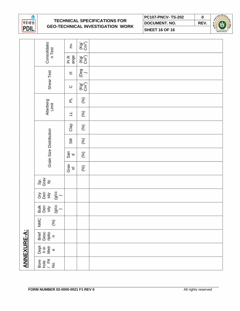
6.3 Report shall also contain the summary of various soil parameters evaluated, in a Performa as given in ANNEXURE- A enclosed.
6 4 Report shall contain character and genesis of soil.
6.5 Detailed bore-logs, subsoil sections, laboratory and field test results both in tabular as well as in graphical form and a plot plan showing locations and reduced levels of bore holes and other tests.
6.6 Results obtained and their interpretation.
6.7 Recommendation for type, depth, ultimate and safe bearing pressure and settlement of foundations for the following structures:
a) Process units, power plants etc., which carry a heavy Unit load.
b) Non plant structures such as administrative buildings etc., which are lightly loaded.
c) Storage tanks and other structures founded at or near ground surface.
6. 8 Recommendations shall also be given for allowable bearing pressure and settlements for foundations of sizes ranging from 1 to 10 metres placed at different depths ranging from surface to 3 metres below the ground surface.
6. 9 Aggressiveness of soil and soil water to reinforced concrete and steel and other building materials.
6.10 Suitability of soil and degree of compaction of fill for the pavement and tank farms and recommendation for thickness of pavement for class AA and Class A loadings.
6.11 Modulus of subgrade reaction for pressure ranging up to 3 Kg/cm². The recommended values shall include the effect of size, shape and depth of foundation.
6.12 In case of poor soil conditions recommendations are to be made for the following:
a) Ground improvement techniques, stabilising slopes, etc. adopting internationally accepted norms and practices considering economy of foundation system. In case of ground improvement, type(s) of improvement method(s) recommended, depth of

TECHNICAL SPECIFICATIONS FOR GEO-TECHNICAL INVESTIGATION WORK
PC107-PNCV- TS-202 0 DOCUMENT. NO. REV. SHEET 15 OF 16
_________________________________________________________________________________________________ FORM NUMBER 02-0000-0021 F1 REV 0 All rights reserved
treatment and settlements and bearing capacity estimates after treatment shall be indicated.
b) Pile foundations, if considered necessary. If so, type(s) of pile recommended, depth of pile, depth of fixity, negative skin friction, safe load capacity for different sizes of piles.
All recommendations shall be supported by back up calculations.
6.13 Any other information of special significance encountered during investigation and likely to have a bearing on design and construction.
6.14 Interim reports based on the data available shall be supplied to the Engineer-in-Charge on demand.
TECHNICAL SPECIFICATIONS FOR GEO-TECHNICAL INVESTIGATION WORK
PC107-PNCV- TS-202 0 DOCUMENT. NO. REV. SHEET 16 OF 16
_________________________________________________________________________________________________ FORM NUMBER 02-0000-0021 F1 REV 0 All rights reserved
AN
NEX
UR
E-A
:
Con
solid
atio
n Te
st m
v
(Kg/
Cm
2 )
Pr.R
ange
(Kg/
Cm
2 )
She
ar T
est
Ø
(Deg .)
C
(Kg/
Cm
2 )
Atte
rber
g Li
mit PL
(%)
LL
(%)
Gra
in S
ize
Dis
tribu
tion Cla
y
(%)
Silt
(%)
San d (%
)
Gra
vel
(%)
Sp.
Gra
vity
Dry
D
en sity
(g/c
c)
Bul
k D
en sity
(g/c
c)
NM
C
(%)
Brie
f D
esc
riptio n
Dep
th
in
Met
re
Bor
eho
le
/ Pi
t N
o.

PREAMBLE TO SCHEDULE OF RATES FOR GEO-TECHNICAL INVESTIGATION WORKS
PC107-PNCV-PR-202 0 DOCUMENT.NO. REV. SHEET 1 OF 6
___________________________________________________________________________________________________ FORM NUMBER 02-0000-0021 F1 REV 3 All rights reserved
PREAMBLE TO
SCHEDULE OF RATES FOR
GEO-TECHNICAL INVESTIGATION WORKS
0 11.04.16 ISSUED FOR TENDER GC GC BRIJESH
REV DATE PURPOSE PREPARED REVIEWED APPROVED

PREAMBLE TO SCHEDULE OF RATES FOR GEO-TECHNICAL INVESTIGATION WORKS
PC107-PNCV-PR-202 0 DOCUMENT.NO. REV. SHEET 2 OF 6
________________________________________________________________________________________________________ FORM NUMBER 02-0000-0021 F2 REV 2 All rights reserved
NOTES
1. The Tenderer shall refer to the “Technical Specifications“ before quoting their Rates. The rates quoted shall be inclusive of all the works specified therein, for the successful completion of the work, including submission of Initial as well as Final reports, after incorporating client’s/owner’s comments., complete, as specified in the tender document.
2. The Tenderer shall note that the supply of Manpower, arranging precise instruments, cutting of wild bushes etc. required for proper execution of the work, shall be their responsibility.
3. The Tenderer shall note that the supply /procurement of all the materials, required for the job, shall be their responsibility
4. The Tenderers are specially advised to visit the site prior to quoting rates, as no change in rates and amount will be accepted later on for any reason whatsoever.
5. The tenderer shall note that the quantities of different items as given below are tentative based on available drawings/ informations collected from site and are subject to variation and they shall not be entitled to claim anything extra or compensation on this account. Owner / consultant does not guarantee the work under each item the “Schedule of rates”. Quotation of individual item may vary up to any extent. The total quantum of work may vary up to 25%on either side of the total awarded contract value and on this account, no variation of quoted rates of item will be permitted

PREAMBLE TO SCHEDULE OF RATES FOR GEO-TECHNICAL INVESTIGATION WORKS
PC107-PNCV-PR-202 0 DOCUMENT.NO. REV. SHEET 3 OF 6
________________________________________________________________________________________________________ FORM NUMBER 02-0000-0021 F2 REV 2 All rights reserved
1.00 GENERAL 1.01 The plans have been evolved tentatively based on information available with Owner /
Consultant but the dimensions and details etc. are liable to changes. The Tenderers shall not be entitled to claim any higher rate or compensation on this account. The tender drawings are intended mainly to give an indication of the probable type of works. The successful Tenderers will, however, be required to execute the work as per detailed approved drawings issued to them from time to time. Owner reserves the right to add / delete any of works mentioned in the N.I.T., during the currency of the contract.
1.02 The Tenderers shall note that the quantities of the different Items, as given in the "Schedule of Rates" are tentative based on tentative tender drawings and are subject to variation and they shall not be entitled to claim any higher rate or compensation on this account. Owner / Consultant reserves the right to change / modify the size and type of sections at any time. Owner / Consultant does not guarantee work under each item of the Schedule of Quantities. The total quantum of work may vary up to 25% on either side and nothing extra will be paid on this account. Quantum of individual item may vary to any extent.
1.03 The Tenderers shall be fully responsible for the correct setting out and execution of the work in accordance with approved drawings which will be supplied to them progressively. All tools, tackles, construction equipments etc., required for the successful execution / construction of the complete work, shall be responsibility of the Tenderers.
1.04 The quantities given in the "Schedule of Rates" are approximate and are given only for the guidance for quoting rates. Payments on bills shall, however, be made on actual measurements of quantities of work done as per approved drawings. Unless otherwise specified, measurements of quantities shall be taken as per Indian Standards IS: 1200.
1.05 The rates to be inserted in the "Schedule of Rates" are to be inclusive of the value of the work described under several items including all costs and expenses which may be required for the construction of the work described together with all taxes, general risks, liabilities and obligations such as temporary buildings / hutments, fencing, watching, lighting, insurance, labour regulations, indemnity, maintenance and the like. The prices shall be inclusive of all labours, materials, tools, plants, equipment, hoists, tackles, scaffoldings, the sundries, etc., as may be necessary for the completion of the work in all respects.
1.06 No work shall be undertaken at site until detailed approved drawings have been issued by the Owner / Consultant in writing. Subsequent revision in the drawings which become necessary shall be incorporated and revised drawings issued to the Contractor who shall execute the work as per the latest revised drawings. Nothing extra will be paid on this account and no claim whatsoever will be entertained on this account. The Owner / Consultant reserves to themselves the right to modify / revise / alter etc. in any drawing supplied to the Contractor.

PREAMBLE TO SCHEDULE OF RATES FOR GEO-TECHNICAL INVESTIGATION WORKS
PC107-PNCV-PR-202 0 DOCUMENT.NO. REV. SHEET 4 OF 6
________________________________________________________________________________________________________ FORM NUMBER 02-0000-0021 F2 REV 2 All rights reserved
1.07 Any fabrication / construction done before final approval of the drawings shall be the Contractor's responsibility.
1.08 In case of any discrepancy between the description of items given in the "Schedule of Rates" and Specifications, drawings and other documents, the decision of the Owner / Consultant in writing shall be final, binding and conclusive for the purpose of this contract.
1.09 The term "Design and drawings" mentioned in the description of Items in the "Schedule of Rates" means the detailed approved design drawings marked "Good for Construction".
1.10 The work "As described", "As shown", "As directed" or "As approved", "As mentioned" in the description of Items shall mean as directed in design or detailed drawings and as directed by the Engineer-in-Charge.
1.11 The Owner shall furnish the Contractor with only reference points of the job site and the Contractor shall at his own cost and initiative, set out the works to the satisfaction of the Engineer-in-Charge but shall solely be responsible for the accuracy of such setting up not withstanding satisfaction as aforesaid of the Engineer-in-Charge or any other assistance rendered by the Engineer-in-Charge for the purpose.
1.12 The Contractor shall provide, fix and be responsible for the maintenance of all stakes, templates, level marks, profiles and the like and shall take all precautions necessary to prevent their removal or disturbance, and shall be responsible for the consequence of such removal or disturbance and for their efficient and timely reinstatement. The Contractor shall also be responsible for the maintenance of all survey marks, boundary marks, distance marks and centre line marks, whether existing or supplied / fixed by the Contractor.
1.13 Before commencing the work, the Contractor shall at his own cost and initiative provide all necessary references, level posts, pegs, bamboos, flags, ranging rods, strings and other materials for proper layout of the work in accordance with the scheme for fixing bench marks acceptable to the Engineer-in-Charge. The centre of longitudinal or face line and cross line shall be marked by means of small masonry pillars. Each pillar shall have distinct mark at the center to enable a theodolite to be set over it. No work shall be started until all these points are approved by the Engineer-in-Charge in writing.
But such approval shall not relieve the Contractor of any of his responsibilities in respect of the adequacy or accuracy, thereof. The Contractor shall also provide all labour, material and other facilities necessary for the proper checking of layout and inspection of the points during construction.
1.14 Pillars bearing geodetic marks located at the site / unit of works under construction should be protected and fenced by the Contractor.
1.15 On completion of works, the Contractor must submit to the Engineer-in-Charge the geodetic documents according to which the work was carried out.

PREAMBLE TO SCHEDULE OF RATES FOR GEO-TECHNICAL INVESTIGATION WORKS
PC107-PNCV-PR-202 0 DOCUMENT.NO. REV. SHEET 5 OF 6
________________________________________________________________________________________________________ FORM NUMBER 02-0000-0021 F2 REV 2 All rights reserved
1.16 The Contractor shall be exclusively responsible for the provision and maintenance of horizontal and vertical alignments and levels and for the correctness of every part of the work in accordance there with and shall at his own cost rectify any errors or imperfections therein.
1.17 The Contractor shall at all times during the progress and continuance of the works be responsible for and effectively maintain and uphold in good, substantial, sound and perfect condition of all / and every part of works and shall make good from time to time and at all times as often as the Engineer-in-Charge shall require any damage or defect that may during the above period arise in or be any way connected with works.
1.18 The portion which is under HOLD shown in the approved drawing or the portion which would be brought under HOLD during execution on account of coordinating different activities of other working agencies shall be taken up by the Contractor to execution only after the said HOLD is withdrawn. The Contractor on this account shall not be entitled to claim for any compensation.
1.19 The Contractor shall maintain adequate drainage facilities at the work site at all times during the execution of the work.
1.20 No compensation shall be made by the Owner / Consultant for any damage done by rain or traffic during the execution of the work.
1.21 The Contractor shall afford all reasonable facilities such as scaffolding etc., and cooperation to the various other agencies and Contractors, for services not included in this contract, who may be working on the site simultaneously so that entire work can proceed smoothly and simultaneously to a successful completion. The Tenderer must take all the aforesaid factors into consideration while quoting his rates. Nothing extra shall be paid on any ground out of or relating to the aforesaid factors.
1.22 For details of works, materials and workmanship, attention is invited to the "Schedule of Rates", Scope Drawings, Special Conditions of Contract, Materials and Job Specifications, this section, etc. and the Tenderers must quote the rates keeping in full view the requirement of the said documents.
1.23 Except otherwise clearly stated, CPWD Specifications with Correction Slips ( latest) shall be followed in all Civil, Structural and other allied Works and in absence of CPWD Specifications for any work, relevant Indian Standard codes of practices (latest) shall be followed. Where there are no Specifications available for any work either in CPWD Specifications or in IS Codes of practices, the work shall be carried out as per the direction of Engineer-in-Charge.

PREAMBLE TO SCHEDULE OF RATES FOR GEO-TECHNICAL INVESTIGATION WORKS
PC107-PNCV-PR-202 0 DOCUMENT.NO. REV. SHEET 6 OF 6
________________________________________________________________________________________________________ FORM NUMBER 02-0000-0021 F2 REV 2 All rights reserved
1.24 The following notations have been used throughout the "Schedule of Rates" and Materials and job Specifications:
1. Cu.M Cubic Metre
2. Sq.M Square Metre
3. m. Metre
4. mm Millimeter
5. Cm. / Cms. Centimeter / Centimeters
6. No. / Nos. Number / Numbers
7. Tonne / Te. Metric Tonne
8. Kg. Kilogram
9. RCC Reinforced Cement Concrete
10. PCC Plain Cement Concrete
1.25 The quoted rates shall be applicable for all heights, depths etc. except otherwise clearly stated in the description of items and nothing extra shall be paid to the contractor on this account.
1.26 Description of items and mode of measurement for payment indicated herein shall override those given elsewhere if these are at variance.
1.27 Any materials / accessories / fittings etc. which may not be specifically mentioned in the description of items but which are normally used or necessary are to be provided by the contractor without any extra cost to Owner / Consultant and the work must be completed in all respects.