Temprature sensors
45
Temperature Sensors
-
Upload
sole-michael -
Category
Engineering
-
view
297 -
download
2
Transcript of Temprature sensors
Temperature Sensors
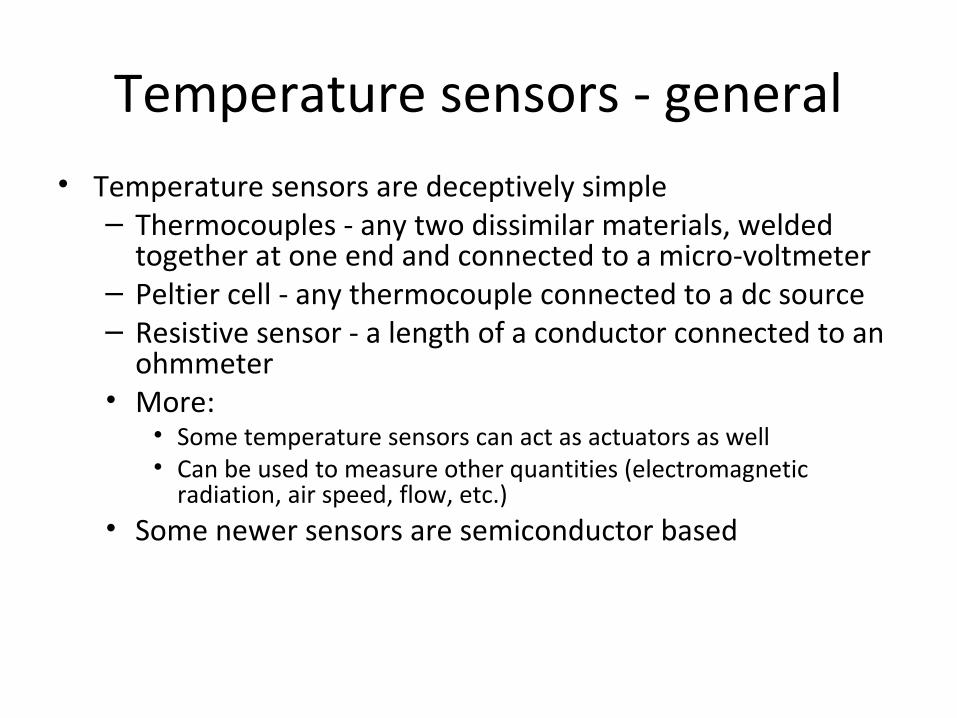
Temperature sensors - general• Temperature sensors are deceptively simple– Thermocouples - any two dissimilar materials, welded
together at one end and connected to a micro-voltmeter– Peltier cell - any thermocouple connected to a dc source– Resistive sensor - a length of a conductor connected to an
ohmmeter• More:
• Some temperature sensors can act as actuators as well• Can be used to measure other quantities (electromagnetic
radiation, air speed, flow, etc.)• Some newer sensors are semiconductor based
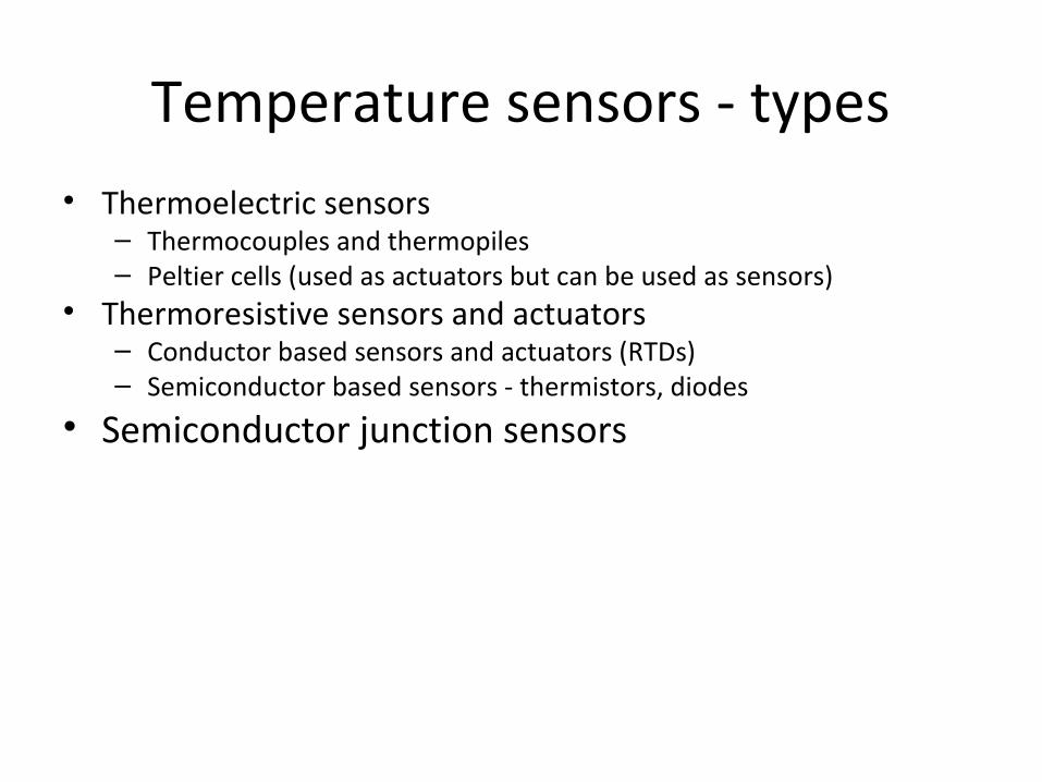
Temperature sensors - types• Thermoelectric sensors
– Thermocouples and thermopiles– Peltier cells (used as actuators but can be used as sensors)
• Thermoresistive sensors and actuators – Conductor based sensors and actuators (RTDs)– Semiconductor based sensors - thermistors, diodes
• Semiconductor junction sensors
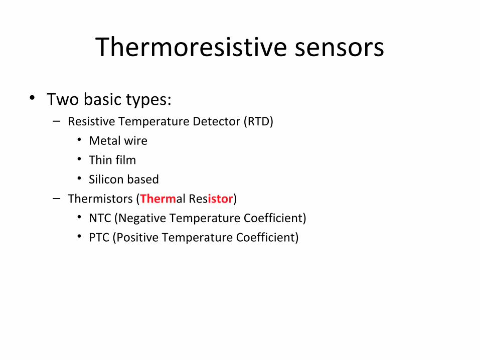
Thermoresistive sensors
• Two basic types:– Resistive Temperature Detector (RTD)
• Metal wire• Thin film• Silicon based
– Thermistors (Thermal Resistor)• NTC (Negative Temperature Coefficient)• PTC (Positive Temperature Coefficient)
Resistance temperature detectors
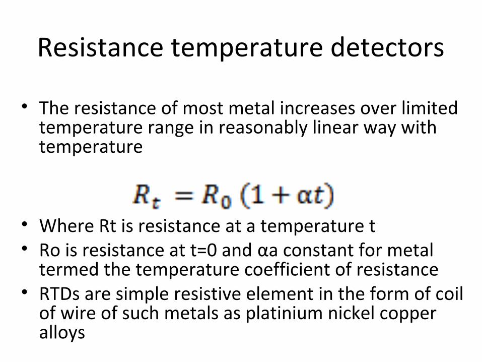
• The resistance of most metal increases over limited temperature range in reasonably linear way with temperature
• Where Rt is resistance at a temperature t• Ro is resistance at t=0 and αa constant for metal
termed the temperature coefficient of resistance• RTDs are simple resistive element in the form of coil
of wire of such metals as platinium nickel copper alloys
Thermoresistive effect
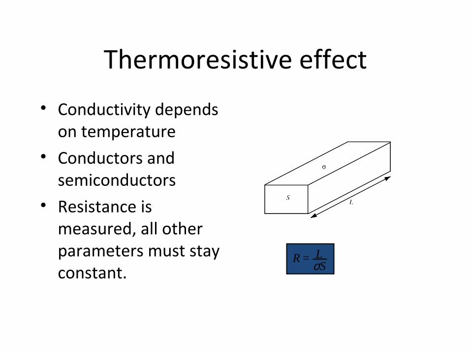
• Conductivity depends on temperature
• Conductors and semiconductors
• Resistance is measured, all other parameters must stay constant.
R = LσS
Thermoresistive effect (cont.)
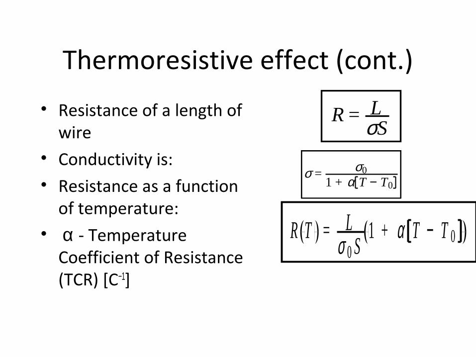
• Resistance of a length of wire
• Conductivity is:• Resistance as a function
of temperature:• α - Temperature
Coefficient of Resistance (TCR) [C−1]
R = LσS
σ = σ01 + α T − T0
R T = Lσ 0 S
1 + α T − T 0
Thermoresistive effect (cont.)
• T is the temperature [°C ] • σ0 is the conductivity of the conductor at the
reference temperature T0. • T0 is usually given at 20°C but may be given at
other temperatures as necessary. • α - Temperature Coefficient of Resistance
(TCR) [C−1] given at T0
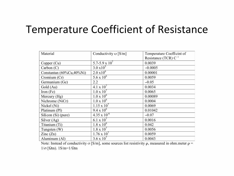
Temperature Coefficient of Resistance
Material Conductivity [S/m] Temperature Coefficint of Resistance (TCR) C
Copper (Cu) 5.7-5.9 x 10⁷ 0.0039 Carbon (C) 3.0 x10⁵ 0.0005 Constantan (60%Cu,40%Ni) 2.0 x10⁶ 0.00001 Cromium (Cr) 5.6 x 10⁶ 0.0059 Germanium (Ge) 2.2 0.05 Gold (Au) 4.1 x 10⁷ 0.0034 Iron (Fe) 1.0 x 10⁷ 0.0065 Mercury (Hg) 1.0 x 10⁶ 0.00089 Nichrome (NiCr) 1.0 x 10⁶ 0.0004 Nickel (Ni) 1.15 x 10⁷ 0.0069 Platinum (Pl) 9.4 x 10⁶ 0.01042 Silicon (Si) (pure) 4.35 x 10⁻⁶ 0.07 Silver (Ag) 6.1 x 10⁷ 0.0016 Titanium (Ti) 1.8 x 10⁶ 0.042 Tungsten (W) 1.8 x 10⁷ 0.0056 Zinc (Zn) 1.76 x 10⁷ 0.0059 Aluminum (Al) 3.6 x 10⁷ 0.0043 Note: Instead of conductivity [S/m], some sources list resistivity , measured in ohm.meter = 1/ [ m). 1S/m=1/ m
Other considerations
• Tension or strain on the wires affect resistance• Tensioning a conductor, changes its length and cross-
sectional area (constant volume)– has exactly the same effect on resistance as a change in
temperature.– increase in strain on the conductor increases the
resistance of the conductor (strain gauge)
• Resistance should be relatively large (25Ω and up)
Construction - wire RTD• A spool of wire (length)
– Similar to heating elements– Uniform wire– Chemically and dimensionally stable in the sensing range– Made thin (<0.1mm) for high resistance
• Spool is supported by a glass (pyrex) or mica support– Similar to the way the heating element in a hair drier is supported– Keeps strain at a minimum and allows thermal expansion– Smaller sensors may not have an internal support.
• Enclosed in a glass, ceramic or metal enclosure– Length is from a few cm, to about 50cm
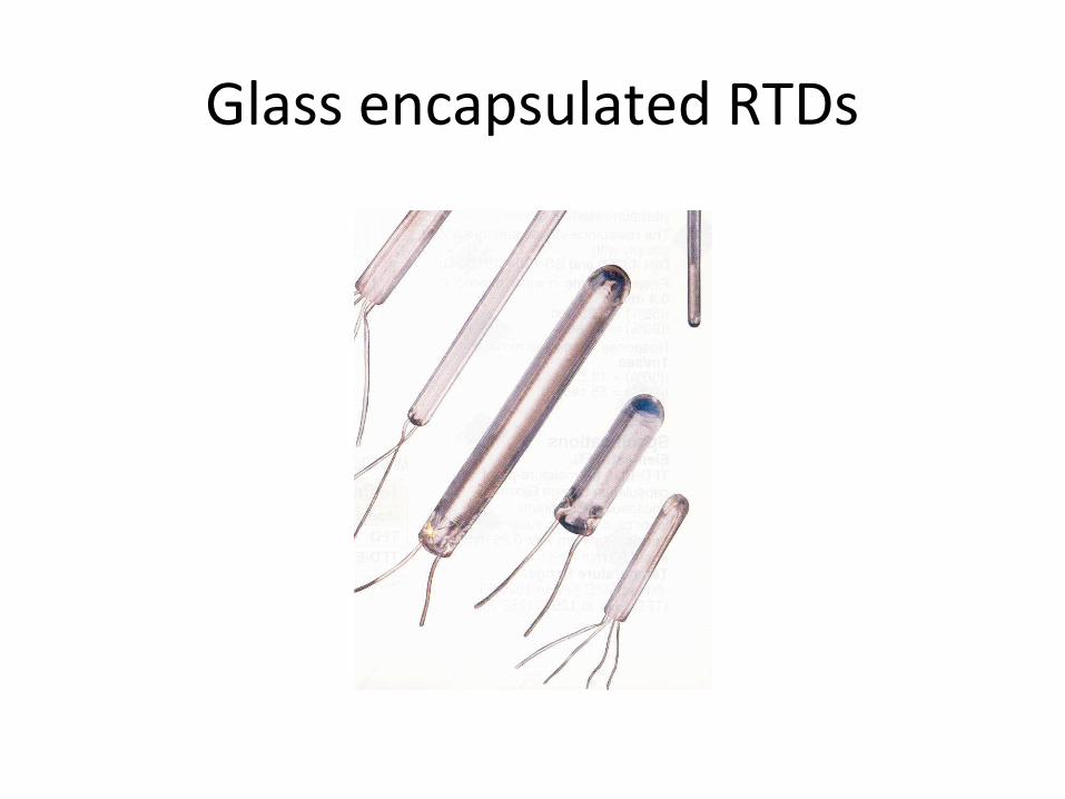
Glass encapsulated RTDs
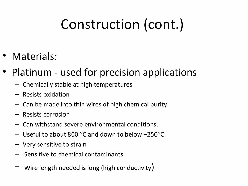
Construction (cont.)
• Materials:• Platinum - used for precision applications
– Chemically stable at high temperatures– Resists oxidation– Can be made into thin wires of high chemical purity – Resists corrosion – Can withstand severe environmental conditions. – Useful to about 800 °C and down to below –250°C. – Very sensitive to strain – Sensitive to chemical contaminants
– Wire length needed is long (high conductivity)
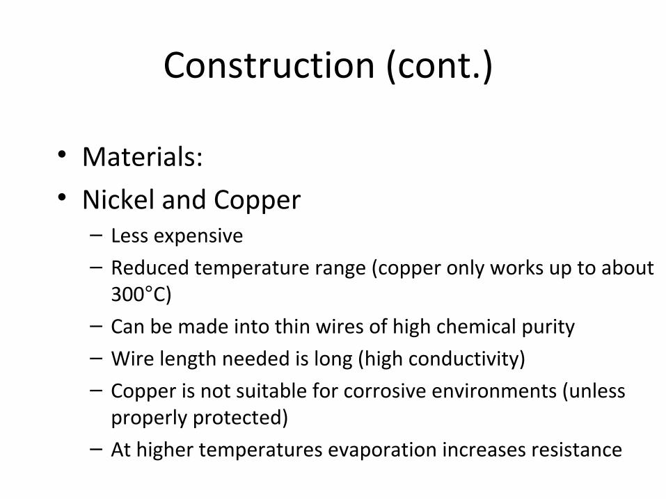
Construction (cont.)
• Materials:• Nickel and Copper– Less expensive– Reduced temperature range (copper only works up to about
300°C)– Can be made into thin wires of high chemical purity – Wire length needed is long (high conductivity)– Copper is not suitable for corrosive environments (unless
properly protected)– At higher temperatures evaporation increases resistance
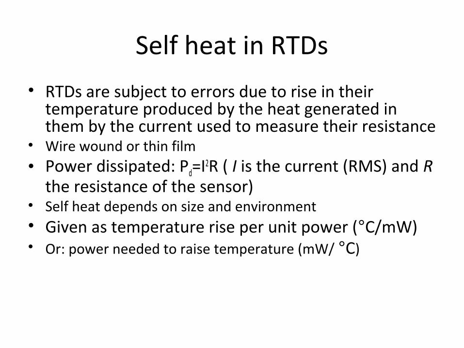
Self heat in RTDs
• RTDs are subject to errors due to rise in their temperature produced by the heat generated in them by the current used to measure their resistance
• Wire wound or thin film• Power dissipated: Pd=I2R ( I is the current (RMS) and R
the resistance of the sensor)• Self heat depends on size and environment• Given as temperature rise per unit power (°C/mW)• Or: power needed to raise temperature (mW/ °C)
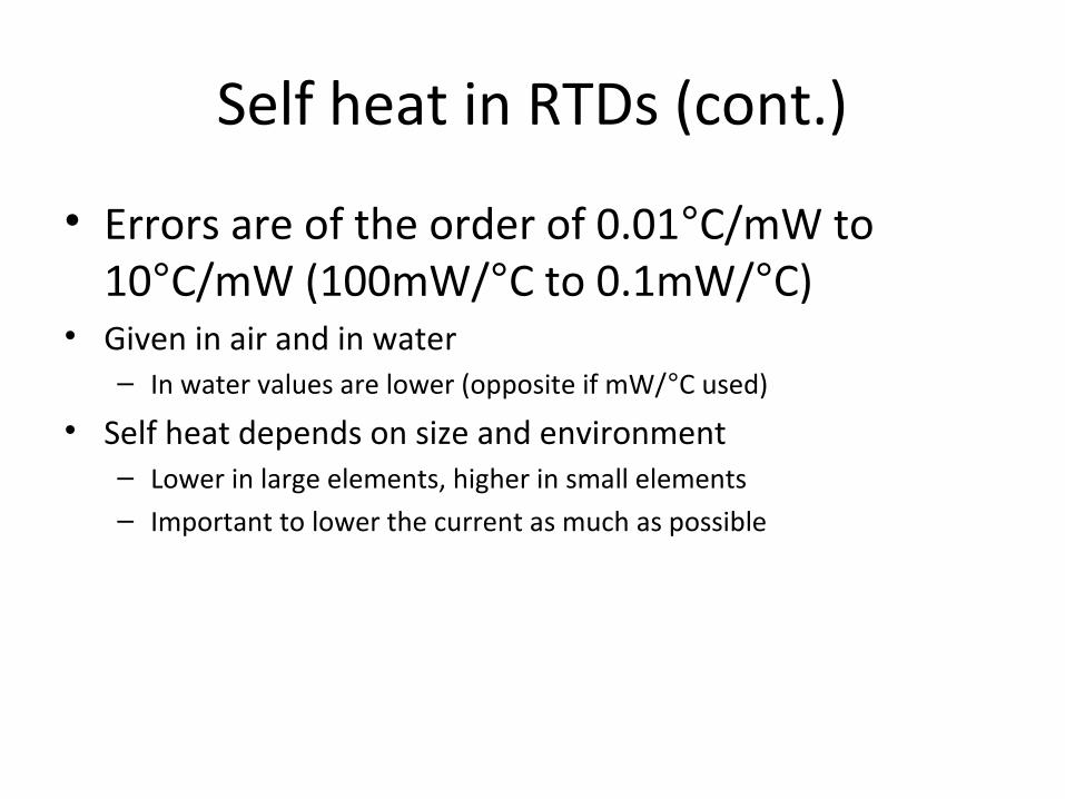
Self heat in RTDs (cont.)
• Errors are of the order of 0.01°C/mW to 10°C/mW (100mW/°C to 0.1mW/°C)
• Given in air and in water– In water values are lower (opposite if mW/°C used)
• Self heat depends on size and environment– Lower in large elements, higher in small elements– Important to lower the current as much as possible
Response time in RTDs
• Response time • Provided as part of data sheet• Given in air or in water or both, moving or stagnant• Given as 90%, 50% (or other) of steady state• Generally slow• Wire RTDs are slower• Typical values
– 0.5 sec in water to 100 sec in moving air
Thermistors
• Are small pieces of materials made from mixture of metal oxides such as chromium cobalt iron manganese, and nickel
• Thermistors: Thermal resistor• Became available: early 1960’s• Based on oxides of semiconductors– High temperature coefficients– NTC– High resistances (typically)
Thermistors (cont.)
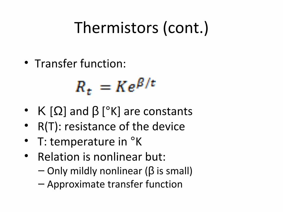
• Transfer function:
• Κ [Ω] and β [°K] are constants• R(T): resistance of the device• T: temperature in °K• Relation is nonlinear but:– Only mildly nonlinear (β is small)– Approximate transfer function
Construction
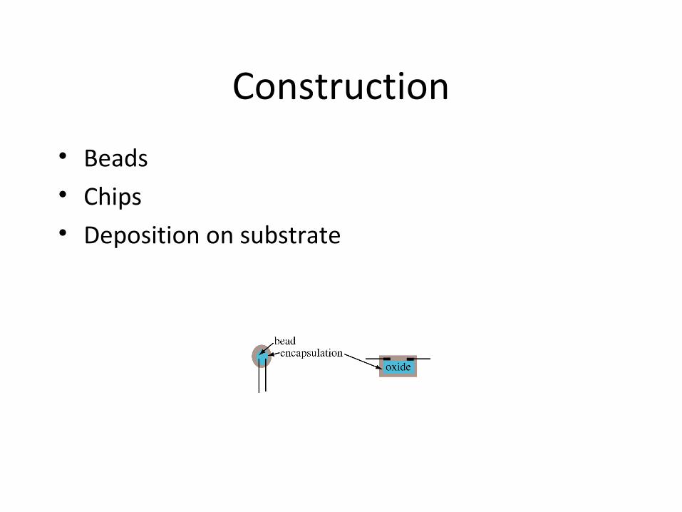
• Beads • Chips• Deposition on substrate
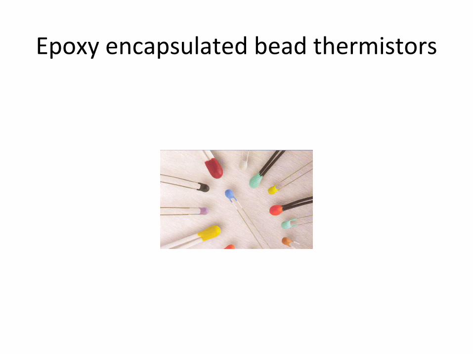
Epoxy encapsulated bead thermistors
Thermistors - properties
• Most are NTC devices• Some are PTC devices• PTC are made from special materials– Not as common– Advantageous when runaway temperatures are
possible
Thermistors - properties
• Self heating errors as in RTDs but:– Usually lower because resistance is higher– Current very low (R high)– Typical values: 0.01°C/mW in water to 1°C/mW in air
• Wide range of resistances up to a few MΩ• Can be used in self heating mode
– To raise its temperature to a fixed value– As a reference temperature in measuring flow
• Repeatability and accuracy:– 0.1% or 0.25°C for good thermistors
Thermistors - properties
• Temperature range:– − 50 °C to about 600 °C– Ratings and properties vary along the range
• Linearity– Very linear for narrow range applications– Slightly nonlinear for wide temperature ranges
• Available in a wide range of sizes, shapes and also as probes of various dimensions and shapes
• Some inexpensive thermistors have poor repeatability - these must be calibrated before use.
Thermoelectric sensors
• Among the oldest sensors (over 150 years)• Some of the most useful and most common• Passive sensors: they generate electrical emfs
(voltages) directly– Measure the voltage directly. – Very small voltages - difficult to measure– Often must be amplified before interfacing– Can be influenced by noise
Thermoelectric sensors (cont.)
• Simple, rugged and inexpensive• Can operate on almost the entire range of
temperature from near absolute zero to about 2700°C.
• No other sensor technology can match even a fraction of this range.
• Can be produced by anyone with minimum skill• Can be made at the sensing site if necessary
Thermoelectric sensors (cont.)
• Only one fundamental device: the thermocouple• There are variations in construction/materials– Metal thermocouples– Thermopiles - multiple thermocouples in series– Semiconductor thermocouples and thermopiles– Peltier cells - special semiconductor thermopiles used as
actuators (to heat or cool)
Themocouple - analysis
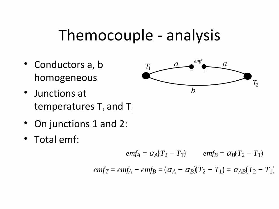
• Conductors a, b homogeneous
• Junctions at temperatures T2 and T1
• On junctions 1 and 2:• Total emf:
emfA = αA T2 − T1 emfB = αB T2 − T1
emfT = emfA − emfB = αA − αB T2 − T1 = αAB T2 − T1
Thermocouple - analysis
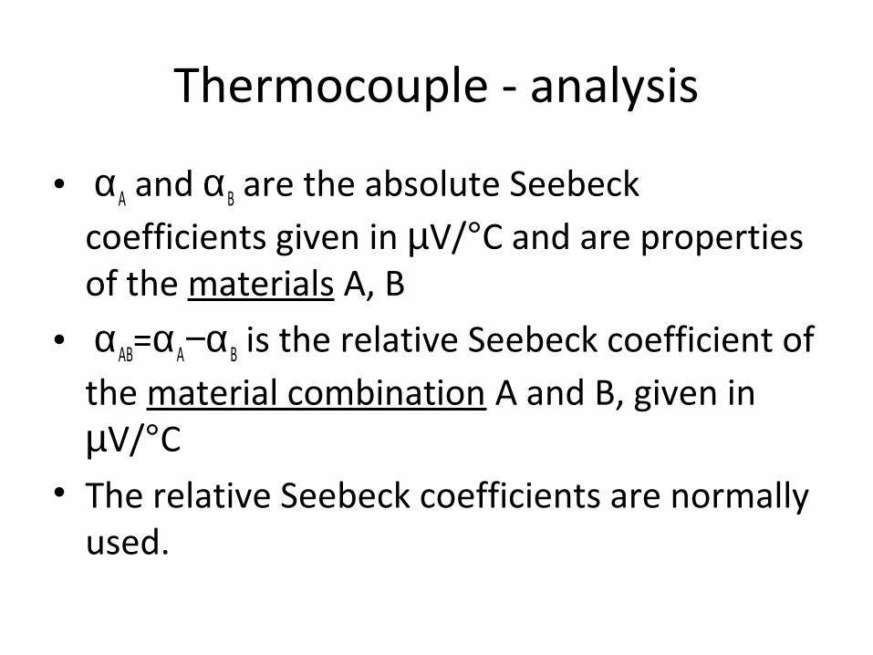
• αA and αB are the absolute Seebeck coefficients given in µV/°C and are properties of the materials A, B
• αAB=αA−αB is the relative Seebeck coefficient of the material combination A and B, given in µV/°C
• The relative Seebeck coefficients are normally used.
Absolute Seebeck coefficients
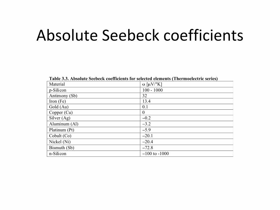
Table 3.3. Absolute Seebeck coefficients for selected elements (Thermoelectric series) Material [ V/°K] p-Silicon 100 - 1000 Antimony (Sb) 32 Iron (Fe) 13.4 Gold (Au) 0.1 Copper (Cu) 0 Silver (Ag) 0.2 Aluminum (Al) 3.2 Platinum (Pt) 5.9 Cobalt (Co) 20.1 Nickel (Ni) 20.4 Bismuth (Sb) 72.8 n-Silicon 100 to -1000
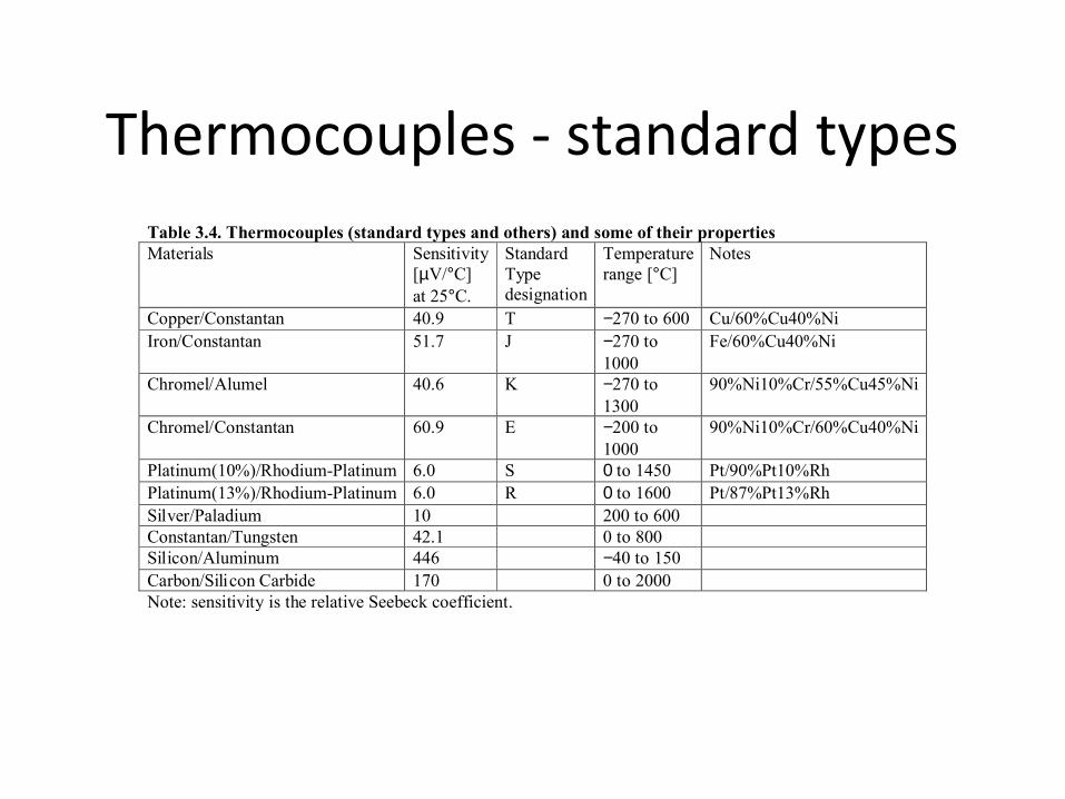
Thermocouples - standard typesTable 3.4. Thermocouples (standard types and others) and some of their propertiesMaterials Sensitivity
[µV/°C]at 25°C.
StandardTypedesignation
Temperaturerange [°C]
Notes
Copper/Constantan 40.9 T −270 to 600 Cu/60%Cu40%NiIron/Constantan 51.7 J −270 to
1000Fe/60%Cu40%Ni
Chromel/Alumel 40.6 K −270 to1300
90%Ni10%Cr/55%Cu45%Ni
Chromel/Constantan 60.9 E −200 to1000
90%Ni10%Cr/60%Cu40%Ni
Platinum(10%)/Rhodium-Platinum 6.0 S 0 to 1450 Pt/90%Pt10%RhPlatinum(13%)/Rhodium-Platinum 6.0 R 0 to 1600 Pt/87%Pt13%RhSilver/Paladium 10 200 to 600Constantan/Tungsten 42.1 0 to 800Silicon/Aluminum 446 −40 to 150Carbon/Silicon Carbide 170 0 to 2000Note: sensitivity is the relative Seebeck coefficient.
Seebeck coefficients - notes:
• Seebeck coefficients are rather small – – From a few microvolts to a few millivolts per degree
Centigrade.– Output can be measured directly– Output is often amplified before interfacing to processors– Induced emfs due to external sources cause noise– Thermocouples can be used as thermometers– More often however the signal will be used to take some
action (turn on or off a furnace, detect pilot flame before turning on the gas, etc.)
Thermoelectric laws:
• Three laws govern operation of thermocouples:
• Law 1. A thermoelectric current cannot be established in a homogeneous circuit by heat alone. – This law establishes the need for junctions of
dissimilar materials since a single conductor is not sufficient.
Thermoelectric laws:
Law 2. The algebraic sum of the thermoelectric forces in a circuit composed of any number and combination of dissimilar materials is zero if all junctions are at uniform temperatures. – Additional materials may be connected in the
thermoelectric circuit without affecting the output of the circuit as long as any junctions added to the circuit are kept at the same temperature.
– voltages are additive so that multiple junctions may be connected in series to increase the output.
Thermoelectric laws:
• Law 3. If two junctions at temperatures T1 and T2 produce Seebeck voltageV2 and temperatures T2 and T3 produce voltage V1, then temperatures T1 and T3 produce V3=V1+V2.– This law establishes methods of calibration of
thermocouples.
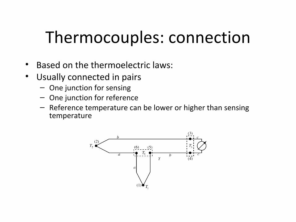
Thermocouples: connection• Based on the thermoelectric laws:• Usually connected in pairs
– One junction for sensing – One junction for reference– Reference temperature can be lower or higher than sensing
temperature
Thermocouples (cont.)
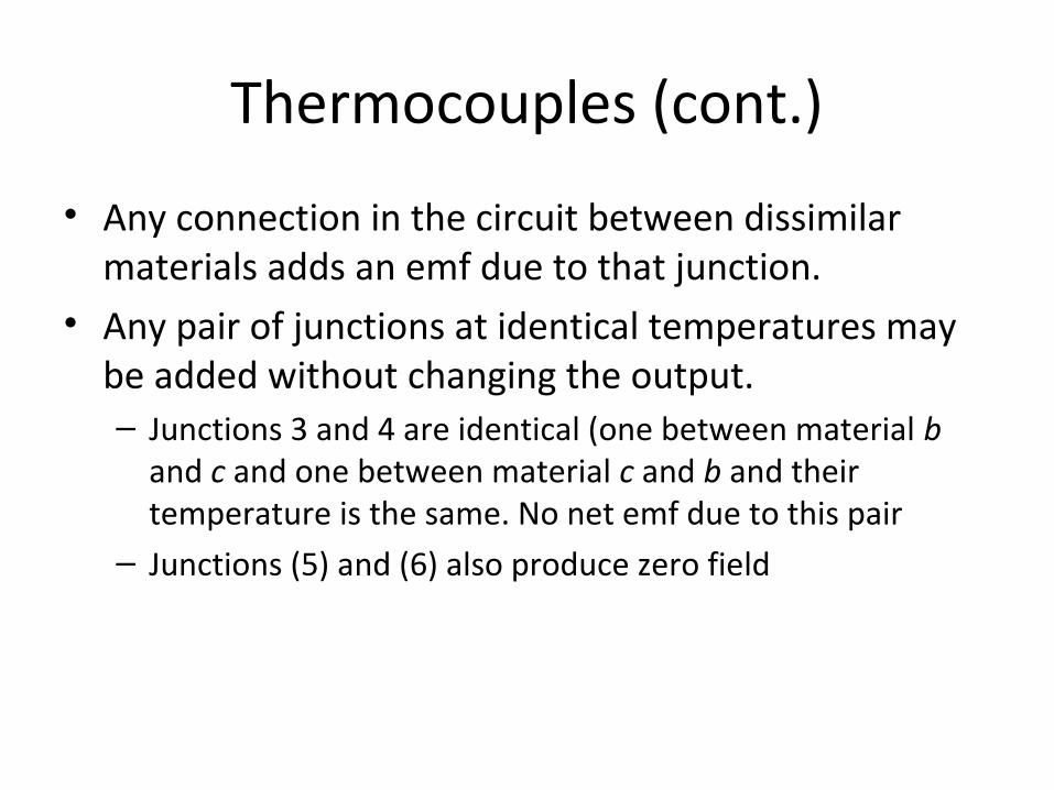
• Any connection in the circuit between dissimilar materials adds an emf due to that junction.
• Any pair of junctions at identical temperatures may be added without changing the output.– Junctions 3 and 4 are identical (one between material b
and c and one between material c and b and their temperature is the same. No net emf due to this pair
– Junctions (5) and (6) also produce zero field
Thermocouples (cont.)
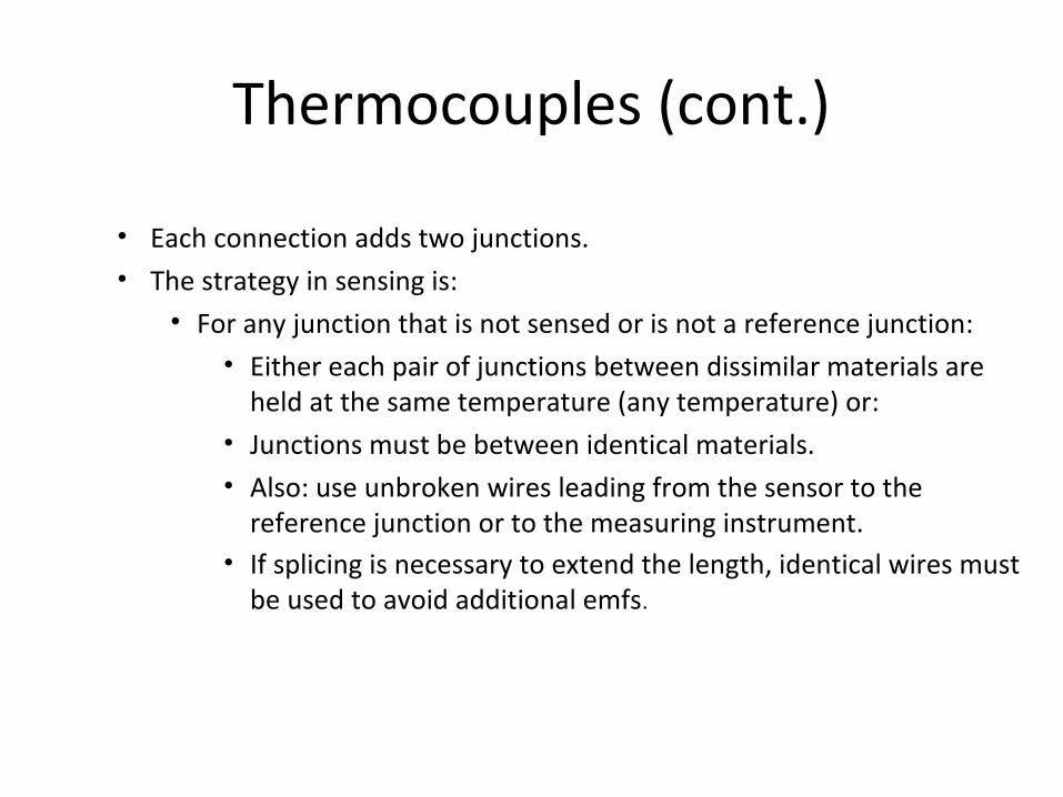
• Each connection adds two junctions. • The strategy in sensing is:
• For any junction that is not sensed or is not a reference junction:• Either each pair of junctions between dissimilar materials are
held at the same temperature (any temperature) or:• Junctions must be between identical materials. • Also: use unbroken wires leading from the sensor to the
reference junction or to the measuring instrument. • If splicing is necessary to extend the length, identical wires must
be used to avoid additional emfs.
Connection without reference
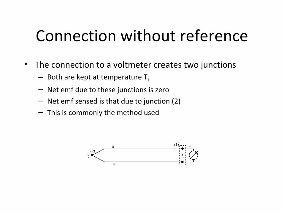
• The connection to a voltmeter creates two junctions– Both are kept at temperature T1
– Net emf due to these junctions is zero– Net emf sensed is that due to junction (2)– This is commonly the method used
Thermocouples - practical considerations
• Choice of materials for thermocouples. Materials affect:– The output emf, – Temperature range – Resistance of the thermocouple.
• Selection of materials is done with the aid of three tables:– Thermoelectric series table– Seebeck coefficients of standard types– Thermoelectric reference table
Bimetal sensors
• Two metal strips welded together• Each metal strip has different coefficient of
expansion• As they expand, the two strips bend. This motion can
then be used to: – move a dial – actuate a sensor (pressure sensor for example) – rotate a potentiometer– close a switch
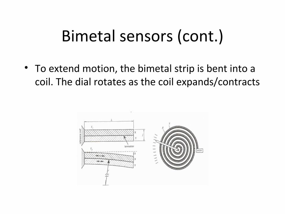
Bimetal sensors (cont.)
• To extend motion, the bimetal strip is bent into a coil. The dial rotates as the coil expands/contracts
Bimetal sensors (cont.)
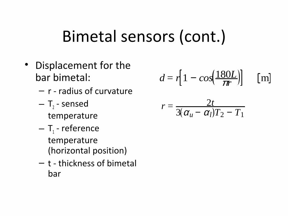
• Displacement for the bar bimetal:– r - radius of curvature– T2 - sensed
temperature– T1 - reference
temperature (horizontal position)
– t - thickness of bimetal bar
d = r 1 − cos 180Lπr m
r = 2t3 αu − αl T2 − T1
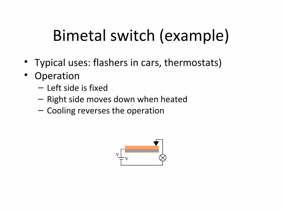
Bimetal switch (example)• Typical uses: flashers in cars, thermostats)• Operation– Left side is fixed– Right side moves down when heated– Cooling reverses the operation
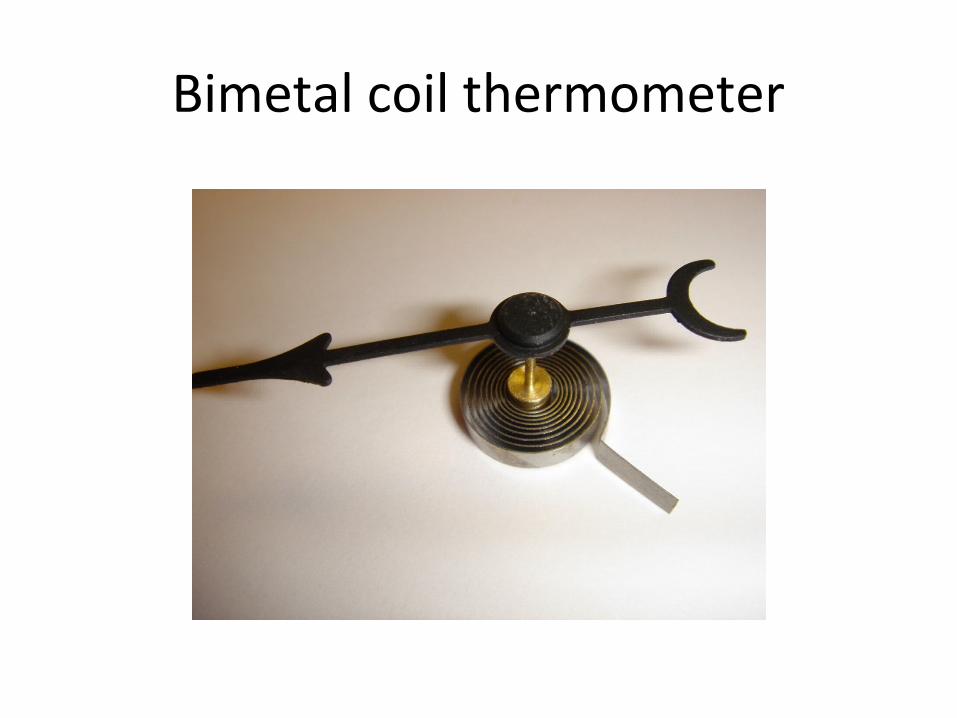
Bimetal coil thermometer