Temporally Gating a Slow-Scan CCD with a Liquid Crystal Shutter
4
Temporally Gating a Slow-Scan CCD with a Liquid Crystal Shutter PAUL L. EDMISTON, SILVIA KOLCHENS, and S. SCOTT SAAVEDRA* Department o[ Chemistry, University of Arizona, Tucson, Arizona 85721 Index Headings: Time-resolved luminescence; Fluorescence microscopy; CCD; Liquid crystal shutter; Spectroscopic techniques. INTRODUCTION The application of charge-coupled device (CCD) tech- nology to high-resolution luminescence microscopy is a recent development. The very high sensitivity, linear re- sponse, and field uniformity that are characteristic of a slow-scan, scientific CCD camera yield data of sufficient quality to make quantitative image analysis possible. 1,2 However, the low temporal resolution of current CCD cameras is a major disadvantage. A CCD with a read noise level of less than 10 electrons typically has a read- out rate in the 40-200 kHz range, which precludes the acquisition of a time-resolved image integrated over mul- tiple excitation pulses without the use of an external gating device. Imaging in the time domain can potentially increase both the information content and the sensitivity of luminescence microscopy.4 For example: (1) fluores- cent probe distributions can be resolved temporally as well as spatially, yielding improved image contrast; and (2) temporally gated detection of long-lived lumines- cence discriminates against scattered light and autoflu- orescence, which can yield improved sensitivity2 7 Both image intensifiers3,6 and mechanical choppers 7 have been used to temporally gate a slow-scan CCD. The time resolution of an image intensifier is excellent. How- ever, these devices typically have a high dark current, a low quantum efficiency, a low field uniformity, and a less linear response, in comparison to a scientific CCD. 6 In addition, the efficiency of coupling an image intensifier output to a CCD is less than 15%. An alternative is a mechanical chopper rotating out of phase with the ex- citation pulse# ,s Using a chopper eliminates the unde- sirable electro-optical effects associated with an image intensifier but significantly decreases the time resolution. Placing a chopper in the emission train also introduces a rise- and fall-time bias. If the time required to sweep the chopper window through the cross section of the emission path is comparable to or greater than the life- time of the luminescence being measured, then the lu- minescence decay function will be superimposed across the image in one dimension. A third disadvantage of a chopper is that the detector gate width (the time window during which the detector is exposed to long-lived emis- Received 7 October 1992. * Author to whom correspondence should be sent. sion by the gating device) cannot be readily adjusted. This problem makes it difficult to optimize the detection system for different probes and/or different modes of detection. An alternative approach to temporally gating a CCD camera is the liquid crystal shutter (LCS), a solid- state device with a response time in the its domain. Re- ported here is an evaluation of an LCS-gated CCD system for time-resolved luminescence imaging. EXPERIMENTAL All chemicals were obtained from standard commercial sources and used as received. The Tb chelate, diethylene- triaminetetraacetic acid p-aminosalicylate-Tb (DTTA- pAS-Tb), was synthesized as previously described. 9 DTTA-pAS forms a fluorescent 1:1 complex with Tb 3÷, and has a lifetime of about 1.5 ms and a quantum yield of 0.1 in aerated water. A schematic diagram of the experimental arrangement for time-resolved imaging is shown in Fig. 1. The 325- nm output of a helium-cadmium laser (Liconix 3207N) is mechanically chopped at 400 Hz. Two wheels are mounted on the chopper; varying the offset between them allows the duty cycle to be adjusted from 0 to 50 %. In the experiments reported here, the duty cycle was ap- proximately 20%. The beam is focused with a 90-mm- FL lens into a cuvet, which is mounted on the sample stage of a Nikon Diaphot inverted microscope. Light is collected through the bottom of the cuvet with a 4 × objective, passed through a bandpass filter centered at 535 nm (535DF45, Omega Optical), and refocused through the LCS onto the CCD array (Tektronix TK512CB) mounted in a cryogenic dewar (Photometrics, Tucson, AZ). The camera controller was configured for a readout rate of 40 kHz at a resolution of 16 bits. The CCD was cooled to -108°C for all measurements. The LCS (PV100-F, Displaytech, Boulder, CO) is used as a high-speed shutter to control exposure of the CCD to light. It is a solid-state device consisting of a ferroelec- tric liquid crystal film mounted between two crossed po- larizers. Application of a positive voltage to the film ro- tates the polarization of light passed by the first polarizer L S I He-Cd laser I I I A-D conversion, counter/timer [~] I inverted and digital I0 T_ o I o I I N"iter chopper (~ ~-----~ LCS driver ] I'~CCD camera I controller I camera head Fro. 1. Block diagram of the time-resolved imaging apparatus. The functions of and interactions between the individual components are discussed in the text. 250 Volume 47, Number 2, 1993
Transcript of Temporally Gating a Slow-Scan CCD with a Liquid Crystal Shutter
Temporally Gating a Slow-Scan CCD with a Liquid Crystal Shutter
P A U L L. E D M I S T O N , S ILVIA K O L C H E N S , and S. S C O T T SAAVEDRA* Department o[ Chemistry, University of Arizona, Tucson, Arizona 85721
Index Headings: Time-resolved luminescence; Fluorescence microscopy; CCD; Liquid crystal shutter; Spectroscopic techniques.
INTRODUCTION
The application of charge-coupled device (CCD) tech- nology to high-resolution luminescence microscopy is a recent development. The very high sensitivity, linear re- sponse, and field uniformity that are characteristic of a slow-scan, scientific CCD camera yield data of sufficient quality to make quantitative image analysis possible. 1,2 However, the low temporal resolution of current CCD cameras is a major disadvantage. A CCD with a read noise level of less than 10 electrons typically has a read- out rate in the 40-200 kHz range, which precludes the acquisition of a time-resolved image integrated over mul- tiple excitation pulses without the use of an external gating device. Imaging in the time domain can potentially increase both the information content and the sensitivity of luminescence microscopy. 4 For example: (1) fluores- cent probe distributions can be resolved temporally as well as spatially, yielding improved image contrast; and (2) temporally gated detection of long-lived lumines- cence discriminates against scattered light and autoflu- orescence, which can yield improved sensitivity2 7
Both image intensifiers 3,6 and mechanical choppers 7 have been used to temporally gate a slow-scan CCD. The time resolution of an image intensifier is excellent. How- ever, these devices typically have a high dark current, a low quantum efficiency, a low field uniformity, and a less linear response, in comparison to a scientific CCD. 6 In addition, the efficiency of coupling an image intensifier output to a CCD is less than 15%. An alternative is a mechanical chopper rotating out of phase with the ex- citation pulse# ,s Using a chopper eliminates the unde- sirable electro-optical effects associated with an image intensifier but significantly decreases the time resolution. Placing a chopper in the emission train also introduces a rise- and fall-time bias. If the time required to sweep the chopper window through the cross section of the emission path is comparable to or greater than the life- time of the luminescence being measured, then the lu- minescence decay function will be superimposed across the image in one dimension. A third disadvantage of a chopper is that the detector gate width (the time window during which the detector is exposed to long-lived emis-
Received 7 October 1992. * Author to whom correspondence should be sent.
sion by the gating device) cannot be readily adjusted. This problem makes it difficult to optimize the detection system for different probes and/or different modes of detection. An alternative approach to temporally gating a CCD camera is the liquid crystal shutter (LCS), a solid- state device with a response time in the its domain. Re- ported here is an evaluation of an LCS-gated CCD system for time-resolved luminescence imaging.
EXPERIMENTAL
All chemicals were obtained from standard commercial sources and used as received. The Tb chelate, diethylene- triaminetetraacetic acid p-aminosalicylate-Tb (DTTA- pAS-Tb), was synthesized as previously described. 9 DTTA-pAS forms a fluorescent 1:1 complex with Tb 3÷, and has a lifetime of about 1.5 ms and a quantum yield of 0.1 in aerated water.
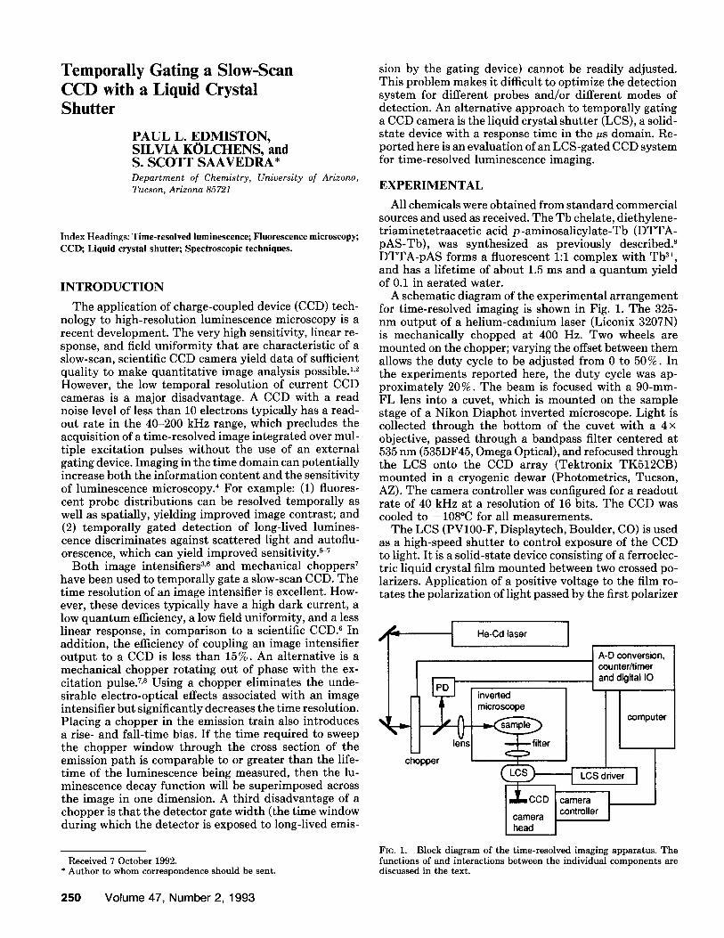
A schematic diagram of the experimental arrangement for time-resolved imaging is shown in Fig. 1. The 325- nm output of a helium-cadmium laser (Liconix 3207N) is mechanically chopped at 400 Hz. Two wheels are mounted on the chopper; varying the offset between them allows the duty cycle to be adjusted from 0 to 50 %. In the experiments reported here, the duty cycle was ap- proximately 20%. The beam is focused with a 90-mm- FL lens into a cuvet, which is mounted on the sample stage of a Nikon Diaphot inverted microscope. Light is collected through the bottom of the cuvet with a 4 × objective, passed through a bandpass filter centered at 535 nm (535DF45, Omega Optical), and refocused through the LCS onto the CCD array (Tektronix TK512CB) mounted in a cryogenic dewar (Photometrics, Tucson, AZ). The camera controller was configured for a readout rate of 40 kHz at a resolution of 16 bits. The CCD was cooled to -108°C for all measurements.
The LCS (PV100-F, Displaytech, Boulder, CO) is used as a high-speed shutter to control exposure of the CCD to light. It is a solid-state device consisting of a ferroelec- tric liquid crystal film mounted between two crossed po- larizers. Application of a positive voltage to the film ro- tates the polarization of light passed by the first polarizer
L S I He-Cd laser I
I I A-D conversion, counter/timer
[ ~ ] I inverted and digital I0
T_ o I o I I N"iter
chopper (~ ~ - - - - - ~ LCS driver ]
I'~CCD camera I controller
I camera head
Fro. 1. Block diagram of the time-resolved imaging apparatus. The functions of and interactions between the individual components are discussed in the text.
2 5 0 Volume 47, Number 2, 1993
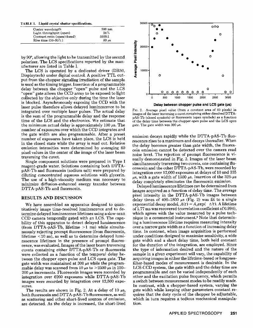
TABLE I. Liquid crystal shutter specifications. 300oo
Center wavelength 500 nm Light throughput (open) 24% Contrast ratio (open/closed) 5500:1 Rise time (10-90%) 80 #s
by 90 ° , allowing the light to be transmitted by the second polarizer. The LCS specifications reported by the man- ufacturer are listed in Table I.
The LCS is operated by a dedicated driver (DR50, Displaytech) under digital control. A positive TTL out- put from the chopper signaling irradiation of the sample is used as the timing trigger. Insertion of a programmable delay between the chopper "open" pulse and the LCS "open" gate allows the CCD array to be exposed to light collected by the objective only during the time the laser is blocked. Asynchronously exposing the CCD with the laser pulse therefore allows delayed luminescence to be integrated over multiple laser pulses. The actual delay is the sum of the programmable delay and the response time of the LCS and the electronics. We estimate that the minimum actual delay is approximately 100 #s. The number of exposures over which the CCD integrates and the gate width are also programmable. After a preset number of exposures have taken place, the LCS is held in the closed state while the array is read out. Relative emission intensities were determined by averaging 60 pixel values in the center of the image of the laser beam traversing the cuvet.
Single component solutions were prepared in Type I reagent-grade water. Solutions containing both DTTA- pAS-Tb and fluorescein (sodium salt) were prepared by diluting concentrated aqueous solutions with glycerin. The use of a high-viscosity medium was necessary to minimize diffusion-enhanced energy transfer between DTTA-pAS-Tb and fluorescein.
RESULTS AND DISCUSSION
We have assembled an apparatus designed to quan- titatively image time-resolved luminescence and to de- termine delayed luminescence lifetimes using a slow-scan CCD camera temporally gated with an LCS. The capa- bility of this apparatus to detect delayed luminescence (from DTTA-pAS-Tb, lifetime >1 ms) while simulta- neously rejecting prompt fluorescence (from fluorescein, lifetime < 10 ns), as well as to determine delayed lumi- nescence lifetimes in the presence of prompt fluores- cence, was evaluated. Images of the laser beam traversing cuvets containing either DTTA-pAS-Tb or fluorescein were collected as a function of the temporal delay be- tween the chopper open pulse and LCS open gate. The gate width was maintained at 300 tts while the program- mable delay was scanned from 10 its to >2500 #s in 100- 200 its increments. Fluorescein images were recorded by integration over 6200 exposures while DTTA-pAS-Tb images were recorded by integration over 12,500 expo- sures.
The results are shown in Fig. 2. At a delay of 10 #s, both fluorescein and DTTA-pAS-Tb fluorescence, as well as scattering and other short-lived sources of emission, are detected. As the delay is increased, the short-lived
c 20000
Q
a. 0
10000 Q
Fro. 2.
00 • • •
0
• •
0
@
0
@
000
0
@
o o o 0 0 0 o o 0 0 o o
0 i I i i I i I
0 500 1000 1500 2000 2500 3000
Delay between chopper pulse and LCS gate (ps) Average pixel value (from a constant area of 60 pixels) in
images of the laser traversing a cuvet containing either dissolved DTTA- pAS-Tb (closed symbols) or fluorescein (open symbols) as a function of the delay time between the chopper open pulse and the LCS open gate. The gate width was 300 us.
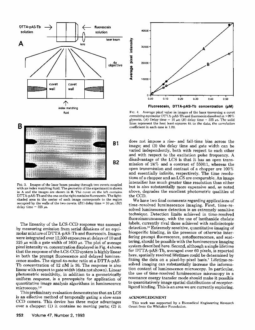
emission decays rapidly while the DTTA-pAS-Tb fluo- rescence rises to a maximum and decays thereafter. When the delay becomes greater than gate width, the fluores- cein emission cannot be detected over the camera read noise level. The rejection of prompt fluorescence is vi- sually demonstrated in Fig. 3. Images of the laser beam simultaneously traversing two cuvets, one containing flu- orescein and the other DTTA-pAS-Tb, were recorded by integration over 12,000 exposures at delays of 10 and 325 its, with a gate width of 1500 #s. Insertion of the 325-#s delay completely eliminates the fluorescein emission.
Delayed luminescence lifetimes can be determined from images acquired as a function of delay time. The average pixel intensity in the DTTA-pAS-Tb images between delay times of 400-1800 #s (Fig. 2) was fit to a single exponential decay model, A(t ) = A o e x p ( - t / t ) . A lifetime of 1.77 ms was recovered (correlation coefficient of 0.994), which agrees with the value measured by a pulse tech- nique in a commercial instrument2 Note that determin- ing a luminescence lifetime requires measuring intensity over a narrow gate width as a function of increasing delay time. In contrast, when image acquisition is performed under conditions designed to maximize sensitivity, a wide gate width and a short delay time, both held constant for the duration of the integration, are employed. Since the type of information desired and the nature of the sample in a given experiment will vary, the capability of acquiring images in either the lifetime-based or longpass- filter-based modes of measurement is desirable. In the LCS-CCD system, the gate width and the delay time are programmable and can be varied independently of each other and the excitation pulse frequency, which permits a switch between measurement modes to be readily made. In contrast, with a chopper-based system, varying the gate width while keeping other parameters constant re- quires that the duty cycle of the chopper be adjustable, which in turn requires a tedious mechanical manipula- tion.
APPLIED SPECTROSCOPY 251
O'I-I'A'pAS-Tb solution
A D 0
fluorescein solution
lens laser beam
4 x objective
cuvet wall
cuvet
wall
index matching fluid
B
B1
B2
FIG. 3. Images of the laser beam passing through two cuvets coupled with an index matching fluid. The geometry of the experiment is shown in A and the images are shown in B. The cuvet on the left contains DTTA-pAS-Tb and the one on the right contains fluorescein. The light- shaded area in the center of each image corresponds to the region occupied by the walls of the two cuvets. (B1) delay time = 10 its; (B2) delay time = 325 its.
The linearity of the LCS-CCD response was assessed by measuring emission from serial dilutions of an equi- molar mixture of DTTA-pAS-Tb and fluorescein. Images were integrated over 12,500 exposures at delays of 10 and 325 us with a gate width of 1600 #s. The plot of average pixel intensity vs. concentration displayed in Fig. 4 shows that the response of the LCS-CCD system is highly linear in both the prompt fluorescence and delayed lumines- cence modes. The signal-to-noise ratio at a DTTA-pAS- Tb concentration of 12 nM is 36. The response is also linear with respect to gate width (data not shown). Linear photometric sensitivity, in addition to a geometrically uniform response, is a prerequisite for application of quantitative image analysis algorithms in luminescence microscopy. 1,2
This preliminary evaluation demonstrates that an LCS is an effective method of temporally gating a slow-scan CCD camera. This device has three major advantages over a chopper: (1) it contains no moving parts; (2) it
m Q X
O
O
40000 -
30000 •
20000"
10000 •
0 • | • m • i - ! - !
0.00 0.10 0.20 0,30 0.40 0.S0
Fluoresceln, DTTA-pAS-Tb concentrat ion (pM)
FIG. 4. Average pixel value in images of the laser traversing a cuvet containing equimolar DTTA-pAS-Tb and fluorescein dissolved in > 99 % glycerin. (A) Delay time = 10 tts; (B) delay time = 325 #s. The solid lines represent the best least-squares fit to the data; the correlation coefficient in each case is 1.00.
does not impose a rise- and fall-time bias across the image; and (3) the delay time and gate width can be varied independently, both with respect to each other and with respect to the excitation pulse frequency. A disadvantage of the LCS is that it has an open trans- mission of 24% and a contrast of 5500:1, whereas the open transmission and contrast of a chopper are 100% and essentially infinite, respectively. The time resolu- tions of a chopper and an LCS are comparable. An image intensifier has much greater time resolution than either but is also substantially more expensive and, as noted above, degrades the excellent photometric qualities of the CCD.
We have two final comments regarding applications of time-resolved luminescence imaging. First, time-re- solved luminescence detection is an extremely sensitive technique. Detection limits achieved in time-resolved fluoroimmunoassay, with the use of lanthanide chelate labels, currently rival those achieved with radioisotopic detection. 1° Extremely sensitive, quantitative imaging of biospecific binding, in the presence of otherwise inter- fering prompt fluorescence, autofluorescence, and scat- tering, should be possible with the luminescence imaging system described here. Second, although a single lifetime for DTTA-pAS-Tb, averaged over 60 pixels, is reported here, spatially resolved lifetimes could be determined by fitting the data on a pixel-by-pixel basisY Lifetime-re- solved imaging can substantially increase the informa- tion content of luminescence microscopy. In particular, the use of time-resolved luminescence microscopy in a resonance energy transfer mode should make it possible to quantitatively image spatial distributions of receptor- ligand binding. This is an area we are currently exploring.
A C K N O W L E D G M E N T
This work was supported by a Biomedical Engineering Research Grant from the Whitaker Foundation.
252 Volume 47, Number 2, 1993
1. Y. Hiraoka, J. W. Sedat, and D. A. Agard, Science 238, 36 (1987). 2. C. E. Hooper and R. E. Ansorge, TRAC 9, 269 (1990). 3. J. R. Lakowicz and K. W. Berndt, Rev. Sci. Instrum. 62, 1727
(1991). 4. T. M. Jovin and D. J. Arndt-Jovin, Ann. Rev. Biophys. Biophys.
Chem. 18, 271 (1989).
5. A. S. Verkman, Comment Mol. Cell. Biophys. 7, 173 (1991). 6. G. T. Reynolds, Comment Mol. Cell. Biophys. 5, 297 (1988). 7. G. Marriot, R. M. Clegg, D. J. Arndt-Jovin, and T. M. Jovin, Bio-
phys. J. 60, 1374 (1991). 8. C. A. Parker, Analyst 94, 161 (1969). 9. S. S. Saavedra and E. G. Picozza, Analyst l l4 , 835 (1989).
10. E. Soini and T. LSvgren, CRC Crit. Rev. Anal. Chem. 18, 105 (1987).
APPLIED SPECTROSCOPY 253