Temperature/Process Controller FB900 FB400cfnewsads.thomasnet.com/pnn-pdf/466884.pdf ·...
12
FB900 FB400 R Temperature/Process Controller
Transcript of Temperature/Process Controller FB900 FB400cfnewsads.thomasnet.com/pnn-pdf/466884.pdf ·...

FB900FB400
R
Temperature/Process Controller
High Performance Digital controller
FB900
FB400
Plug-in lock released bar
A/M R/LR/S
Digital input
Power feedforwardPower feedforward
Remote setting input
PFF input
CommunicationWIN UCI (setting/monitoring tool)
ANSI, MODBUS communication
Digital outputUp to 4 pointsUp to 4 pointsp pp p
Analog retransmissionpoutput
Heat/Cool controlPosition proportioningcontroll
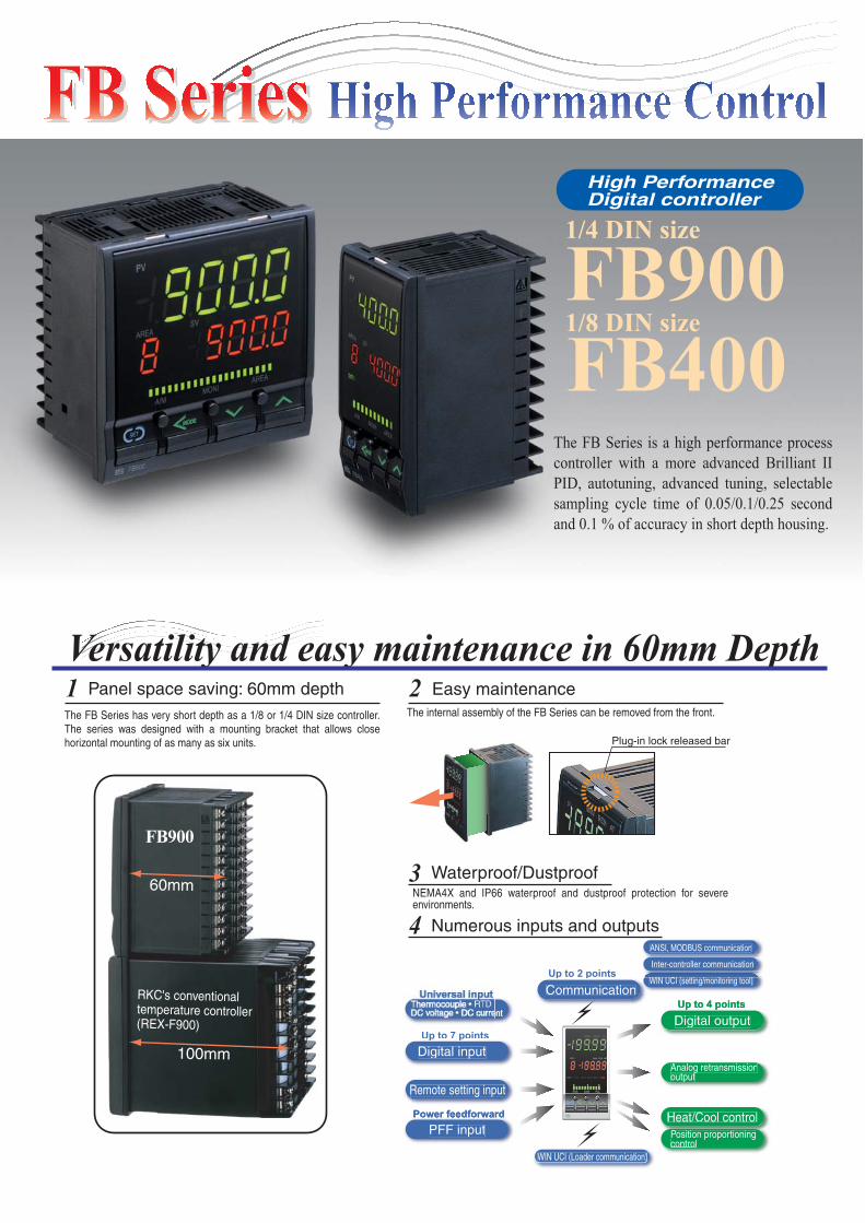
The FB Series is a high performance process
controller with a more advanced Brilliant II
PID, autotuning, advanced tuning, selectable
sampling cycle time of 0.05/0.1/0.25 second
and 0.1 % of accuracy in short depth housing.
The FB Series has very short depth as a 1/8 or 1/4 DIN size controller. The series was designed with a mounting bracket that allows close horizontal mounting of as many as six units.
Panel space saving: 60mm depth1The internal assembly of the FB Series can be removed from the front.
NEMA4X and IP66 waterproof and dustproof protection for severe environments.
Easy maintenance 2
Waterproof/Dustproof3
Numerous inputs and outputs4
Versatility and easy maintenance in 60mm Depth
Up to 2 pointsp pInter-controller communication
Up to 7 pointsp p
( )WIN UCI (Loader communication)
1/4 DIN size
1/8 DIN size
FB900
60mm
RKC's conventional temperature controller(REX-F900)
100mm
Autotuning
Brilliant II PID Control
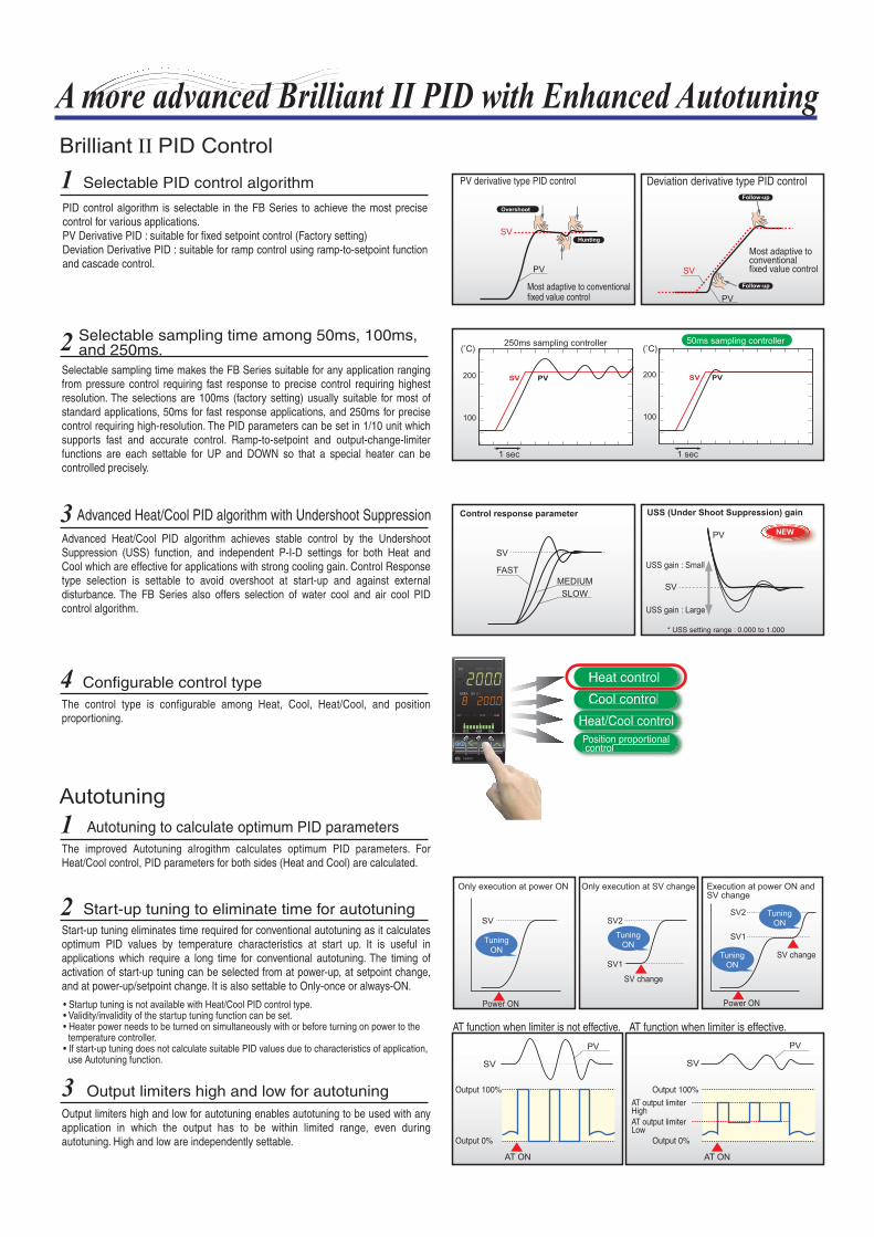
A more advanced Brilliant II PID with Enhanced Autotuning
SV
Only execution at power ON Only execution at SV change Execution at power ON and SV change
Power ON
SV2
SV1
SV2
SV1
Advanced Heat/Cool PID algorithm with Undershoot Suppression
SV
SV
USS gain : Small
USS gain : Large
* USS setting range : 0.000 to 1.000
FAST
MEDIUM
SLOW
Control response parameter USS (Under Shoot Suppression) gain
PV NEW
Selectable PID control algorithm
SV
SVPV
PV
Overshoot
Hunting
SV change
Tuning
ON
AT function when limiter is effective.AT function when limiter is not effective.
SV
AT output limiterHighAT output limiterLow
PV
Output 100%
Output 0%
Output 100%
Output 0%
AT ON AT ON
1 sec 1 sec
200 SV PV
100
250ms sampling controller( C) ( C)
200 SV PV
100
A/M R/LR/S
FB400
PV
SV MV
Heat control
Heat/Cool control
1PID control algorithm is selectable in the FB Series to achieve the most precise control for various applications.PV Derivative PID : suitable for fixed setpoint control (Factory setting)Deviation Derivative PID : suitable for ramp control using ramp-to-setpoint function and cascade control.
Selectable sampling time makes the FB Series suitable for any application ranging from pressure control requiring fast response to precise control requiring highest resolution. The selections are 100ms (factory setting) usually suitable for most of standard applications, 50ms for fast response applications, and 250ms for precise control requiring high-resolution. The PID parameters can be set in 1/10 unit which supports fast and accurate control. Ramp-to-setpoint and output-change-limiter functions are each settable for UP and DOWN so that a special heater can be controlled precisely.
Advanced Heat/Cool PID algorithm achieves stable control by the Undershoot Suppression (USS) function, and independent P-I-D settings for both Heat and Cool which are effective for applications with strong cooling gain. Control Response type selection is settable to avoid overshoot at start-up and against external disturbance. The FB Series also offers selection of water cool and air cool PID control algorithm.
The improved Autotuning alrogithm calculates optimum PID parameters. For Heat/Cool control, PID parameters for both sides (Heat and Cool) are calculated.
Start-up tuning eliminates time required for conventional autotuning as it calculates optimum PID values by temperature characteristics at start up. It is useful in applications which require a long time for conventional autotuning. The timing of activation of start-up tuning can be selected from at power-up, at setpoint change, and at power-up/setpoint change. It is also settable to Only-once or always-ON.
Output limiters high and low for autotuning enables autotuning to be used with any application in which the output has to be within limited range, even during autotuning. High and low are independently settable.
The control type is configurable among Heat, Cool, Heat/Cool, and position proportioning.
2
3
4
1
2
3
Selectable sampling time among 50ms, 100ms, and 250ms.
Configurable control type
Autotuning to calculate optimum PID parameters
Start-up tuning to eliminate time for autotuning
• Startup tuning is not available with Heat/Cool PID control type.• Validity/invalidity of the startup tuning function can be set. • Heater power needs to be turned on simultaneously with or before turning on power to the temperature controller.• If start-up tuning does not calculate suitable PID values due to characteristics of application, use Autotuning function.
Output limiters high and low for autotuning
PV derivative type PID control Deviation derivative type PID control
Most adaptive to conventional fixed value control
Most adaptive to conventional fixed value control
Follow-up
Follow-up
50ms sampling controller
Cool control
Position proportional controlt l
Tuning
ON
Tuning
ON
Tuning
ON
Power ON
SV change
SV
PV

A/M R/LR/S
FB400
PV
SV MV
SV MV
A/M R/LR/S
FB400
PV
SV MV
• Resolution can be set.
• Can be set to any of the following selection modes.
(Also possible to invalidate the direct mode selection key function.)
Pressing the MODE select key for 2 sec enables the same mode selection as in the conventional REX-F900/F400.
Three direct function keys enable one-touch operation on frequently used functions such as Auto/Manual, Monitoring display scroll, and Memory area selection. The keys can also be configured as RUN/STOP, Remote/Local, and Auto/Manual keys.
The FB Series features an easy-to-read 20mm height five digit display which can show a range between -19999 and 19999. (The display range varies depending on the input type.)
Set value
Event 1 to 4 Set value
LBA time
LBA dead band
Control response
Overlap/Deadband
Proportional band(Heat and Cool)Proportional band(Heat and Cool)Integral time(Heat and Cool)
Area soak timeLink area number
RUN/STOP
Direct Function Keys
User-friendly key-operation and display
The FB Series has Multi-memory Area function which stores up to 8 sets of control parameters. Parameters in a memory area can be changed at one time by selecting the memory area number through key operation, DI, or communication.
Recipe (Multi-memory Area) Function
Area 1
Area No.
0% -10˚C 0˚C +10˚C100%
A/M MONI AREA
FB900A/M MONI AREA
FB900
• The elapsed time of area soak time can be displayed on the front panel.
Linked area No.
Soak time
Ramp-to-setpoint (Up)
Area1(Step1)
Area2(Step2)
Area3(Step3)
Area4(Step4)
Area5(Step5)
Area6(Step6)
Area7(Step7)
Area8(Step8)
PID/AT
1
Large, Crystal Clear 5-Digit Display Unit2
Bar Graph Display3
4
Up to 16-segment ramp/soak control is available by using the Memory Area function (area soak time, link area number, ramp-to-setpoint Up and Down).
Ramp/Soak Program Control5
Auto Manual
Memory area select
Monitoring display select
Memory area select
Monitoring display select
Auto/Manual
Remote/LocalAuto/Manual
Auto/Manual
RUN/STOP
Remote/Local
Manipulated output Deviation
Derivative band(Heat and Cool)
Ramp-to-setpoint (Up and Down)
Set value
Event 1 to 4 Set value
LBA time
LBA dead band
Control response
Overlap/Deadband
Proportional band(Heat and Cool)Proportional band(Heat and Cool)Integral time(Heat and Cool)
Area soak timeLink area number
Area 8
Derivative band(Heat and Cool)
Ramp-to-setpoint (Up and Down)
The bar graph on the front panel can display control output value (factory setting), deviation between SV and PV, measured value, or CT1/CT2 input value. The FB900 bar graph display resolution is 20 LED segments and there are 10 LED segments for the FB400.

Reinforced Insulation, Lead-free PCBs, Low Power Consumption
Auto-temperature-rise with learning function achieves temperature uniformity at ramp-up without partial thermal expansion even when multiple FB Series controllers are connected. Inter-controller communication by COM port 2 is used to send or receive information among controllers. At start-up, the learning function monitors and evaluates a heat-up balance among channels. Then it calculates ramp-up-rate for each channel to make all heaters follow the temperature-rise-curve of a channel with the longest time to reach setpoint. Up to 32 controllers with 16 groups can be configured.
When automatic temperature rise is not setCH A
CH A CH B CH C CH D
B
DC
All CH Temperature rise completion
Start
All CH Temperature rise completion
Start
When automatic temperature rise is set
Temperature uniformity and stability
Dedicated transformer
Thyristor unit
Power Feed Forward Function
A/M R/LR/SPFF Input
V
Control output
PID output
PFF correction +
CH A
CH BCH C
CH D
CH A
CH BCH C
CH D
CH C
CH D
CH BCH A
CH C
CH D
CH BCH A
RS-485
Up to32 units
A/M R/LR/S A/M R/LR/S A/M R/LR/S A/M R/LR/S A/M R/LR/S A/M R/LR/S A/M R/LR/S
Group 1 Group 16
Temperature Uniformity at Ramp-up1
Power feed forward function constantly monitors the electrical load through a dedicated transformer. It then adjusts control output relative to power supply fluctuations to prevent sudden load output changes to the electrical heating elements.
Power supply circuit of the FB Series has been designed to be reinforcement insulated. It saves cost to perform basic insulation on the equipment side.
Power Feed Forward Function (Optional)2
1
Time
Time
Reinforcement Insulated Power Supply Circuit
The FB Series uses lead-free PCBs complying with EU Directive *.
2 Lead-free Design complying with EU Directive
The power consumption is 30% less than the equivalent model of RKC REX-F900. The saving is 5VA per controller at 240VAC. It also generates less heat and it helps keep temperature low inside the control cabinet.
3 Low Power Consumption, Low Heat Generation
The safety standards on electrical equipment (IEC 61010-1 and JISC 1010-1) request that the secondary side of the equipment which may be touched by the operator should be double insulated or reinforcement insulated* from high voltage causing electric shock.
<Requirements for electrical equipment according to safety standards>
• Insulation safeguarding personnel from electric shock which is equal to double insulation or higher is called "reinforced insulation".
CH A waitCH B waitCH C wait
* WEEE Directive (Waste Electrons/Electrical Equipment Directive) and RoHS Directive (Directive of Restricting the use of Harmful Materials for Electrical Products)

Communicate with a PC via USB port
Loader port (Provided as standard)
USB port
Upload
Data logging and trend graph screen
Temperature monitoring screen• Customize the background with your own picture (bitmap format)
Download
"Win-UCI" software for setup & data logging is free. Simply download "Win-UCI" from the RKC Instrument website (www.rkcinst.com).
RS-485
Up to31 units
RS-232C
Easy setup with Win-UCI
Communication converter : COM-K
USB
CSV File
A/M R/LR/S
A/M R/LR/S A/M R/LR/S A/M R/LR/S
User mapping area
0000 PV monitor0001
SV monitor
PV monitorSV monitorEvent monitorProportional bandIntegral timeDerivative time
0002CT1 monitor
0003CT2 monitor
0XX0
0XX1
0XX2
0XX3
0XX4
0XX5
0XX6
(Up to 16 parameters)
RUN/STOP status
Cable length : 1m
70
(Unit : mm)
26
RS-422A/485
USB
Connector (Phoenix contact)(Included in a converter package)
A/M R/LR/S
FB900
PV
SV MV
39
Easy-setup and Data Monitoring via a standard data port
The FB Series has the loader port (provided as standard) to connect to a PC USB port with Windows2000/XP. The standard port allows setup and data logging to be managed by the PC. The FB Series is recognized as an external device on the PC.
1
With Modbus communication, up to 16 communication parameters can be mapped to continuous addresses to achieve the fastest communication. Mapping is configured on Win-UCI.
2
Easy data monitoring/logging withWin-UCI.
Converter
Converter
Using the Win-UCI, the controller setup and parameter settings can be done from a PC. The parameter settings can be stored on the PC making it easy to copy the same parameters to other FB Series controllers.• The instrument must have a hardware required for selected functions.
When setting up the FB Series via the loader port, the power can be supplied from the PC via the USB port so no power supply cable is necessary. Just connect the cable to the FB Series and setup is ready to go.
Data setting screen
Cable length : 1.5mLoader communication
Mapping function for faster data update
PV monitorSV monitorEvent monitorProportional bandIntegral timeDerivative timeRUN/STOP status
"Seven parameters from 0XX0"
Communicationconverter
The Win-UCI can store maximum 8,000 points of data. Data can be exported as an electronic file in CSV format. It has a trend graph function and data monitoring function.
No power supply cable necessary at setup

A/M R/LR/S
SV
A/M R/LR/S
SV
A/M R/LR/S
Inter-controller Communication (RS-485)
Inter-controller communication
Up to 32 units
Group 1
CH A CH CCH B CH D
Master Slave Master Slave
CH1 CH3CH2 CH4CH1 CH3CH2 CH4
A/M R/LR/SA/M R/LR/SA/M R/LR/SA/M R/LR/SA/M R/LR/SA/M R/LR/SA/M R/LR/SA/M R/LR/S
A/M R/LR/S
A/M R/LR/S A/M R/LR/S
A/M R/LR/S A/M R/LR/S A/M R/LR/S A/M R/LR/S
A/M R/LR/S A/M R/LR/S A/M R/LR/S
CH A • B • C • D
SV MV
RUN RUN RUN RUNA/M R/LR/S
STOPA/M R/LR/S
STOPA/M R/LR/S
STOPA/M R/LR/S
STOP
SV
A/M R/LR/S
SV
A/M R/LR/S
SV
A/M R/LR/S
SV
CC-Link Ethernet
• Released soon
Communicationprotocol converter PLC
MitsubishiMELSEC series
OmronSYSMAC series
Program free
RS-485
MAPMAN
PROFIBUSDeviceNet
COM-JG COM-JLCOM-JHCOM-JC
COM-JE
3The FB Series has a second communication port (COM2) for inter-controller communication. It achieves more precise cascade control and ratio control by sending data via digital communication while conventional cascade controllers send data to slave controllers by analog signal with less resolution.
Open Network Connectivity 4
Auto-temperature-rise with learning function achieves temperature uniformity at ramp-up without partial thermal expansion even when using multiple FB Series controllers.
It is effective when a thermal time-delay exists between the heat source and a control point. A maximum of 30 slave controllers can be connected to one master controller.
If the master controller changes the control set value, the slave controllers will also change the set values by following preset ratios to the master.
When RUN/STOP mode is changed on one controller in a group, the mode of all the other controllers in the same group will be also automatically changed.
• Up to 32 controllers with 16 groups can be configured.
• Up to 32 controllers with 16 groups can be configured.
Auto-temperature-rise with Learning Function
Temperature Ratio Setting
Group RUN/STOP Function
Cascade control
Group 1 Group 2 Group 16
Temperature rise completionStart
Ratio Ratio Ratio Ratio Ratio Ratio
Group 1Group 1
CC-LinkCommunicationConverter
DeviceNetCommunicationConverter
PROFIBUSCommunicationConverter
EthernetCommunicationConverter
The FB Series can be connected to various Open Networks, such as PROFIBUS, DeviceNet, CC-Link, and Ethernet via a gateway. A gateway with the MAPMAN function is available with the FB Series. The MAPMAN function requires no PLC programming and automatically writes process data into the PLC registers and updates parameters continuously.
• Up to 32 controllers with 16 groups can be configured.
Lead free Design complying Lead free Design complying Lead free Design complying
Lead free Design complying
MODBUS protocol
(Note) Time lag among controllers caused by inter-controller communication is (Max.70ms) x (number of controllers connected). Please consider the time lag of inter-controller communication for high-speed process control in which process changes rapidly.
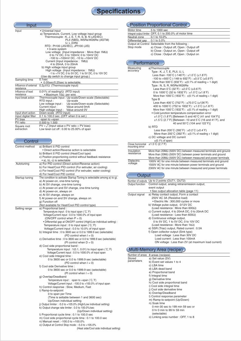
a)Thermocouple Type : K, J, T, E, PLII, U, L Less than -100˚C (-148˚F) : ±1.0˚C (±1.8˚F) -100 to +500˚C (-148 to 932˚F) : ±0.5˚C (±0.9˚F) More than 500˚C (932˚F) : ±(0.1% of reading + 1 digit) Type : N, S, R, W5Re/W26Re Less than 0˚C (32˚F) : ±2.0˚C (±3.6˚F) 0 to 1000˚C (32 to 1832˚F) : ±1.0˚C (±1.8˚F) More than 1000˚C (1832˚F) : ±(0.1% of reading + 1 digit) Type B Less than 400˚C (752˚F) : ±70.0˚C (±126˚F) 400 to 1000˚C (752 to 1832˚F) : ±1.0˚C (±1.8˚F) More than 1000˚C (1832˚F) : ±(0.1% of reading + 1 digit) • Cold junction temperature compensation error ±1.0˚C (1.8˚F) [Between 5 and 40˚C (41 and 104˚F)] ±1.5˚C (2.7˚F) [Between -10 and 5˚C (16 and 41˚F), and 40 and 50˚C (104 and 122˚F)] b) RTD Less than 200˚C (392˚F) : ±0.2˚C (±0.4˚F) More than 200˚C (392˚F) : ±(0.1% of reading + 1 digit) c) DC voltage and DC current ±(0.1% of span) ±1.5˚C (2.7˚F)
More than 20MΩ (500V DC) between measured terminals and groundMore than 20MΩ (500V DC) between power terminals and groundMore than 20MΩ (500V DC) between measured and power terminals1000V AC for one minute between measured terminals and ground1500V AC for one minute between power terminals and ground2300V AC for one minute between measured and power terminals
Performance
Insulationresistance
Dielectricvoltage
a) Brilliant ΙΙ PID control • Direct action/Reverse action is selectableb) Brilliant ΙΙ PID control (Heat/Cool type)c) Position proportioning control without feedback resistance • a), b), c) is selectablea) For PID control (Direct action/Reverse action)b) For Heat/Cool PID control (For extruder, air cooling)c) For heat/Cool PID control (For extruder, water cooling)d) For heat/Cool PID controlThe condition to activate Startup Tuning is selectable among a) to g). a) At power-on, one-time tuningb) At SV change, one-time tuningc) At power-on and SV change, one-time tuningd) At power-on, always one) At SV change, always onf) At power-on and SV change, always ong) Function off(Not available for Heat/Cool PID control type)a) Proportional band : Temperature input : 0 to input span (˚C,˚F) Voltage/Current input : 0.0 to 1000.0% of input span (ON/OFF control when P = 0) • Differential gap at ON/OFF control (High/Low individual setting) : Temperature input : 0 to input span (˚C,˚F) Voltage/Current input : 0.0 to 10.0% of input spanb) Integral time : 0 to 3600 sec or 0.0 to 1999.9 sec (selectable) (PD control when I = 0)c) Derivative time : 0 to 3600 sec or 0.0 to 1999.9 sec (selectable) (PI control when D = 0)d) Cool side proportional band : Temperature input : 1(0.1, 0.01) to input span (˚C,˚F) Voltage/Current input : 0.0 to 1000.0% of input spane) Cool side Integral time : 0 to 3600 sec or 0.0 to 1999.9 sec (selectable) (PD control when I = 0)f) Cool side Derivative time : 0 to 3600 sec or 0.0 to 1999.9 sec (selectable) (PI control when I = 0)g) Overlap/Deadband Temperature input : -span to +span (˚C,˚F) Voltage/Current input : -100.0 to +100.0% of input spanh) Control response : Slow, Medium, Fasti) Ramp-to-setpoint 0 to span per Time (Time is settable between 1 and 3600 sec) Up/Down individual settingj) Output limiter : -5.0 to +105.0% (High/Low individual setting) k) Output change rate limiter : 0.0 to 100.0%/sec (Up/Down individual setting) l) Proportional cycle time : 0.1 to 100.0 secm) Cool side proportional cycle time : 0.1 to 100.0 secn) Manual reset : -100.0 to +100.0%o) Output at Control Stop mode : -5.0 to +105.0% (Heat side/Cool side individual setting)
Control method
Autotuning
Startup tuning
Setting range
5 to 1000 secOFF, 0.1 to 200.0% of motor time0.1 to 10.0%0.1 to 5.0%Selectable from the following : a) Close : Output off, Open : Output offb) Close : Output on, Open : Output offc) Close : Output off, Open : Output on
Motor time
Output at ControlStop mode
Neutral zone
Differential gap
Integral output limiter
Number of outputs
Number of areas
Output function
Output signal
OutputUp to 2 points (OUT1, OUT2)Control output, analog retransmission output,event output • See output allocation table (page 11)a) Relay contact output, Form a contact 250V AC 3A (Resistive load) • Electric life : 300,000 cycles or moreb) Voltage pulse output, 0/12V DC (Load resistance : More than 600Ω)c) Current output, 4 to 20mA DC, 0 to 20mA DC (Load resistance : Less than 600Ω)d) Continuous voltage output, 0 to 5V DC, 1 to 5V DC, 0 to 10V DC (Load resistance : More than 1kΩ)e) SSR (Triac) output, Rated current : 0.5Af) Open collector output (Sink type) Load voltage : Less than 30V DC Load current : Less than 100mA ON voltage : Less than 2V (at maximum load current)
• Universal input a) Temperature, Current, Low voltage input group Thermocouple : K, J, E, T, R, S, B, N (JIS/IEC) PLII (NBS), W5Re/W26Re (ASTM) U, L (DIN) RTD : Pt100 (JIS/IEC), JPt100 (JIS) • 3-wire system Low voltage (Input impedance : More than 1MΩ) 0 to 1V DC, 0 to 100mV, 0 to 10mV DC -100 to +100mV DC, -10 to +10mV DC Current (Input impedance : 1MΩ) 4 to 20mA, 0 to 20mA b) High voltage input group High voltage (Input impedance : 1MΩ) -1 to +1V DC, 0 to 5V DC, 1 to 5V DC, 0 to 10V DC (Use dip switch to change input group.)0.1sec • 0.05sec/0.25sec is selectable.0.2µV/Ω (Thermocouple input)
0.01% of reading/Ω (RTD input) • Maximum 10Ω per wireThermocouple input : Up-scale/Down-scale (Selectable)RTD input : Up-scaleLow voltage input : Up-scale/Down-scale (Selectable)Current input : Value around 0mAHigh voltage input : Value around 0VDown-scale (RTD input)0.1 to 100.0 sec. (OFF when 0 is set.) -span to +span0.500 to 1.500PV = (Input value x PV ratio + PV bias)Low level cut off : 0.00 to 25.00% of span
8 areas (recipes)a) Set value (SV)b) Event set values 1 to 4c) LBA timed) LBA dead bande) Proportional bandf) Integral timeg) Derivative timeh) Cool side proportional bandi) Cool side integral timej) Cool side derivative timek) Overlap/Deadbandl) Control response parameterm) Ramp-to-setpoint (Up/Down)n) Soak time 0 min 00 sec to 199 min 59 sec or 0 hr 0 min to 99 hr 59 min (selectable)o) Linking area number : OFF, 1 to 8
Storedparameters
Specifications
InputInput
Sampling time
Influence of externalresistanceInfluence of leadresistance
Input short actionInput digital filterPV biasPV ratio
Square root extraction
Input break action
Control
Position Proportional Control
Measuring accuracy
Close horizontalmounting error
Multi-Memory Area (recipe)

NEMA4X, IP66 • Waterproof/Dustproof protection only effective from the front in panel mounted installation.
a) 90 to 264V AC (50/60Hz, Selectable) Rating : 100 to 240V ACb) 24V AC ±10% (50/60Hz, Selectable) Rating : 24V ACc) 24V DC ±10% Rating : 24V DCa) 100 to 240V AC type FB900 : 13.0VA (240V), 8.7VA(100V) FB400 : 11.9VA (240V), 7.8VA(100V)b) 24V AC type FB900 : 9.3VA FB400 : 8.2VAb) 24V DC type FB900 : 300mA FB400 : 250mAA power failure of 20m sec or less will notaffect the control action. If power failure of more than 20m sec occurs, controller will restart with the state of HOT start 1, HOT start 2 or COLD start (selectable)Backed up by non-volatile memory (FRAM)• Data retaining period : Approx. 10 years• Number of writing : Approx. 1,000,000,000,000,000 times.(Depending on storage and operating conditions.)-10 to +50˚C (14 to 122˚F)5 to 95% RH (Non condensing)• Absolute humidity : MAX.W.C 29g/cm3 dry air at 101.3kPaFB900 : Approx. 290gFB400 : Approx. 230gFree from corrosive and flammable gas and dust. Free from external noise, vibration, shock and exposure to direct sunlight.CE Mark, UL, C-UL, C-Tick markCompliance with
Standards
Communications
General Specifications
Waterproof/Dustproof
Communication method
Number ofCommunications
Protocol
Communication speed
Bit format a) RKC standard protocol Start bit : 1 Data bit : 7 or 8 Parity bit : 1 (odd or even) or none Stop bit : 1 or 2b) MODBUS protocol Start bit : 1 Data bit : 8 (binary or byte data) Parity bit : 1 (odd or even) or none Stop bit : 1 or 2 (Fixed to 1 bit for parity 1)RS-485 : 32 units (Including host)RS-422A : 16 units (Including host)RS-232C : 1 unit
Supply voltage
Power consumption
Power failure
Memory backup
Ambient temperatureAmbient humidity
Weight
Operatingenvironment
Up to 4 pointsProcess high, Process low, Deviation high, Deviation low,Deviation high/low, Band, Set value high, Set value low,MV value high, MV value low, Cool side MV value high,Cool side MV value low, FBR value high, FBR value low, LBA (Control loop break alarm) • LBA is assignable to event 4.a) Deviation alarm Event set value : -input span to +input span Event action differential gap : 0 to input spanb) Process alarm/Set value alarm Event set value : Same as input range Event action differential gap : 0 to input spanc) MV alarm, FBR alarm -5.0 to +105.0%d) LBA LBA time : 0 to 7200 sec (LBA is OFF when 0 is set.) Dead band : 0 to input spanAssignable to digital output (DO 1 to 4) • See output allocation table (page 11)a) Hold/Re-hold action (Valid for deviation/band/process alarm only) • Hold action is activated at Power-up and STOP to RUN. Re-hold action is activated at Power-up, STOP to RUN, and the control set value change. b) Event action is configurable in case of input abnormality. c) Energized/de-energized action is configurable.d) Delay timer : 0.0 to 600.0 sec e) Interlock (latch) function is configurable.
Event (Alarm)
Output terminals
Other functions
2 points (1 point per CT input)CTL-6-P-N : 0 to 30ACTL-12-S56-10L-N : 0 to 100A0.0 to 100.0A±5% of input value or 2A (whichever is larger) Assignable to output 2 or digital output (DO 2 to 4) • See output allocation table (page 11)
Number of alarms
Number of inputs
CT Type andinput range
Input methodFunction
Display accuracy
Display range
Output terminals
a) Low voltage, current group 0 to 1V DC, 0 to 100mV DC, 0 to 10mV DC 4 to 20mA DC, 0 to 20mA DCb) High voltage group 0 to 5V DC, 1 to 5V DC, 0 to 10V DC• Universal input0.1 sec (with measuring input sampling time of 0.05 sec)0.2 sec (with measuring input sampling time of 0.1 sec)0.5 sec (with measuring input sampling time of 0.25 sec)±0.1% of spanAccuracy
Output type
Output terminals
Output signal
• Use communication port 2
• Exclusive power feed transformer is required. Up to 7 points (DI 1 to 4, DI 5 to 7)Non-voltage contact inputDI 1 to 4 : Memory area selection + Area setDI 5 to 7 : RUN/STOP, Remote/Local, Auto/Manual Alarm interlock reset, • Selectable
Digital Input (DI)
Up to 4 points (DO 1 to 4)Event output, Heater break alarm (HBA), FAILRelay contact output, Form a contact 250V AC 1A (Resistive load)
(Optional)
(Optional)
(Optional)
(DI 1 to 4 : Optional, DI 5 to 7 : Standard)
(Standard)
(Optional)
Number of outputs
Number of event
Event type
Setting range
Output functionOutput signal
Function : Automatic temperature rise, Cascade control, Temperature ratio setting, Group STOP/RUN
Up to 1 point• Assignable to AO (For analog output), output 1 or output 2AO terminal Measured value (PV), Set value (SV)Manipulated value (MV), Deviation (between PV and SV)• Selectable4 to 20mA DC, 0 to 20mA DC (Load resistance : Less than 600Ω)0 to 1V DC, 0 to 5V DC, 1 to 5V DC, 0 to 10V DC (Load resistance : More than 1kΩ)
Resistance valueSampling time
Standard : 100 to 10kΩ (factory default 135Ω)0.1 sec (with measuring input sampling time of 0.05 sec)0.2 sec (with measuring input sampling time of 0.1 sec)0.5 sec (with measuring input sampling time of 0.25 sec)
Specifications
Digital Output (DO)
Input
Sampling time
Number of outputs
(Optional)
(Optional)
(Optional)
Up to 2 points
COM1 : RS-485/RS-422A/RS-232CCOM2 : RS-485 (Can be used for Inter-controller communication)2400bps, 4800bps, 9600bps, 19200bps, 38400bps
a) ANSI X3.28 sub-category 2.5A4 (RKC standard)b) MODBUS-RTU
(Optional)
(Standard)
Inter-controller Communication
Heater Break Alarm (HBA)
Power Feed Forward (PFF) Input
Feedback Resistance (FBR) Input
Analog Retransmission Output (AO)
Remote Setpoint Input • Not available with PFF or CT 2 input.
Maximumconnection

(96 x 96mm 1/4 DIN size)(48 x 96mm 1/8 DIN size)
FB900FB400
Specifications
Digital output
Output 1
Output 2
Power Supply
N
1
4
5
W
X
Y
D
N
1
2
N
A
N
T
1
2
3
4
F
F
D
G
A
W
Z
3
4
Relay contact output
Relay contact output
Digital outputControl output
Voltage pulse output (0/12V DC)
Triac outputOpen collector outputNot supplied
Not supplied
Not supplied
Not supplied
Not supplied
DC mA, mV, V
Voltage pulse output (0/12V DC)
Triac outputOpen collector output
DC mA, mV, V
24V AC/DC100 to 240V AC
DO 4 points (DO1 to DO4)
PFF input (With transformer 100 to 120V AC type)CT input 2 points
PFF input (With transformer 200 to 240V AC type)CT input 1 point + PFF input (With transformer 100 to 120V AC type)CT input 1 point + PFF input (With transformer 200 to 240V AC type)Feedback resistance input
COM1 : RS-232C
No quick start code (Default setting)
Version symbolInstrument version
Specify quick start code 1 and 2 (See page 11)Specify quick start code 1
COM1 : RS-422ACOM1 : RS-485COM1 : RS-232CCOM1 : RS-485COM1 : Not supplied
COM2 : Not suppliedCOM2 : Not suppliedCOM2 : Not suppliedCOM2 : RS-485COM2 : RS-485COM2 : RS-485
Digital input (DI 1 to 4) Area selection
• With digital input (DI 1 to 4) Area selection
No quick start code PID control with AT (Reverse action)
No quick start code
PID control with AT (Direct action)Heat/Cool PID control with ATHeat/Cool PID control with AT for extruder (Air cooling type)Heat/Cool PID control with AT for extruder (Water cooling type)
White caseBlack case
3
4
5
CodeOutput Type CodeOutput Type
0 to 5V DC0 to 1V DC
0 to 10V DC0 to 20mA DC1 to 5V DC
4 to 20mA DC
6
7
8
CT input Power feed forward (PFF) inputFeedback resistance
Communication and Digital input(DI 1 to 4)
Analog retransmissionoutput (AO)
Case color
Quick start code
(OUT 1)
(OUT 2)
M
V
T
D
N
4
N
M
V
T
D
Model and Suffix Code
Output Code Table
See Output Code Table
: Required : Selectable
Model and Suffix Code
See Output Code Table
DC mA, mV, V See Output Code Table
Y
PIDcontrol
Heat/CoolPIDcontrol
Position proportioning control
Alarm LBA HBA
(Relay contactoutput)
(Relay contactoutput)
* When HBA (heater break alarm) is used, select the "CT input" from the model code. ** When inter-controller communication is used, please specify code "W, X or Y (COM2 : RS-485). Remote setpoint input is not available with inter-controller communication.
* 0 to 1 VDC output can be specified only for analog retransmission output.
Control Method
Input and range
Position proportional PID control without FBRNo Code
No Code
Y
N
Hardware coding onlyQuick start code 1
Qui
ck s
tart
cod
e 1
• With digital input (DI 1 to 4) Area selection
• With digital input (DI 1 to 4) Area selection • With digital input (DI 1 to 4) Area selection • With digital input (DI 1 to 4) Area selection • With digital input (DI 1 to 4) Area selection
• With digital input (DI 1 to 4) Area selection
<Area selection>
Input Range Code Table
tototototototototototototototototototototo
-200.0 +400.0˚C-200.0 +800.0˚C
0.0 400.0˚C0.0 800.0˚C
-200 +1372˚C0 400˚C0 800˚C
-250.0 +800.0 F-328.0 +400.0 F
0.0 800.0 F0.0 1600.0 F
-328 +2502 F0 800 F0 1600 F
-200.0 +400.0˚C-200.0 +800.0˚C
0.0 400.0˚C0.0 800.0˚C
-200 +1200˚C0 400˚C0 800˚C
RangeCodeInputK 35K 40K 09K 10K 41
02KK 04K C6K C4K A4K B2K C5K A1K A2J 27J 32J 08J 09J 15J 02J 04
K
J
tototototototototototototototototototototo
-200.0 +700.0 F-328.0 +1200.0 F
0.0 800.0 F0.0 1600.0 F
-328 +2192 F0 800 F0 1600 F
-200.0 +400.0˚C-328.0 +752.0 F
-50 +1768˚C-58 +3214 F-50 +1768˚C-58 +3214 F
-200.0 +700.0˚C-200 +1000˚C
-328.0 +1292.0 F-328 +1832 F
0 1800˚C0 3272 F0 1300˚C0 2372 F
RangeCodeInputJ C7J C6J B6J B2J B9
A1JJ A2T 19T C2S 06S A7R 07R A7E 21E 06E A9E B1B 03B B2N 02N A7
J
T
S
R
E
B
N
Thermocouple
totototototototo
0 1390˚C0 2534 F0 2300˚C0 4200 F
0.0 600.0˚C0.0 1112.0 F0.0 900.0˚C0.0 1652.0 F
RangeCodeInputA 02A A2W 03W A2U 04
B2UL 04L A3
totototototototototo
-100.00 +100.00˚C-200.0 +850.0˚C-200.0 +200.0˚C
-199.99 +199.99 F-328.0 +1562.0 F
-100.00 +100.00˚C-200.0 +640.0˚C
-199.99 +199.99 F-328.0 +1184.0 F-200.0 +200.0 F
RangeCodeInputD 34D 35D 21D C8D C9
29PP 30P C8P C9P D1
Pt100
JPt100
W5Re/W26Re(NBS)PLII
(DIN)U
(DIN)L
(ASTM)
RTD
RangeCodeInput1 012 013 014 015 01
016
DC Current • Voltage
0 to 10mV0 to 100mV0 to 1V0 to 5V0 to 10V1 to 5V
RangeCodeInput7 018 019 019 029 03
0 to 20mA4 to 20mA
-100 to +100mV-1 to +1V
-10 to 10mV
0.0 to 100.0%0.0 to 100.0%
*
**
See Input range Code Table
• Universal input, no model code required on hardware code.

• Quick start code 2 tells the factory to ship with each parameter preset to the values detailed as specified by the customer. Quick start code is not necessarily specified when ordering, unless the preset is requested. These parameters are software selectable items and can be re-programmed in the field via the manual.
Initial set code
Remote setpointinput signal
Output allocation
Event 1 type
Event 2 type
Event 3 type
Event 4 type
CT type
1
0 to 1V DC
0 to 10V DC1 to 5V DC0 to 20mA DC4 to 20mA DCNo event 1
No event 2
Control loop break alarm (LBA)
CT1 : CTL-6-P-N, CT2 : No useCT1 : CTL-12-S56-10L-N, CT2 : No useCT1 : CTL-6-P-N, CT2 : CTL-6-P-NCT1 : CTL-12-S56-10L-N, CT2 : CTL-12-S56-10L-NNo communication 1 (COM1)ANSI/RKC standard protocolMODBUS protocolNo communication 2 (COM2)ANSI/RKC standard protocolMODBUS protocol
Communication 1
Communication 2
0 to 5V DC
N
N
N
N
N
N
Specifications
1
Code
2
3
4
5
6
7
Output 1(OUT 1)
Output 2(OUT 2)
Digital Output 1(DO 1)
Digital Output 2(DO 2)
Digital Output 3(DO 3)
Digital Output 4(DO 4)
Control output 1 Control output 1 HBA
HBA
HBA
HBA
HBA
FAIL
See output allocation table
See event type code table
See event type code tableNo event 3See event type code table
Quick start code 2
Accessories
CodeEvent typeDeviation HighDeviation LowDeviation High/LowBandDeviation High with Alarm HoldDeviation Low with Alarm Hold
Process High with Alarm HoldProcess Low with Alarm Hold
A
B
C
D
E
F
Deviation High/Low with Alarm Hold
Deviation High with Alarm Re-HoldDeviation Low with Alarm Re-HoldDeviation High/Low with Alarm Re-Hold
Process HighProcess Low
G
H
J
K
Output Allocation Table
L
Q
R
T
Set value HighSet value LowMV value HighMV value LowCool side MV value HighCool side MV value Low
V
W
1
2
3
4
0 to 10mV DC0 to 100mV DC
No CT1 and CT2
No event 4See event type code table
Event Type Code Table
Control output 1 Control output 1
Control output 2 Control output 2 Control output 2 Control output 2
Control output 1 Control output 1 Control output 1 (De-energized)
Event 1
Event 1
Event 1
Event 1
Event 1
Event 1
Event 1
Event 2
Event 2
Event 2
Event 2
Event 2
Event 2
Event 3
Event 3
Event 3
Event 3
Event 3
Event 3
Event 4
Event 4
Event 4
Event 4
FAIL(De-energized)
FAIL(De-energized)
• Energized/De-energized is configurable except for the FAIL output. (Factory default setting: Energized) • Invalid for a non-existing output/event function.
(Caution) • When used as heating/cooling control/position proportioning control, select any code of 1 to 4.
5
* Please specify "8" when the remote setpoint input signal is not used.
*
Model Code :
Terminal coverKFB400-58
(FB900 uses 2 unit)
FB400
FB900
Max
.63
Max.70
Max.68
2-M4
5959
±0.5
50
Mounting dimension
* Supplied when power feed forward function is specified.
* When ordering transformer for replacement, please specify one of the following model codes. 100 to 120V AC type : PFT-01 200 to 240V AC type : PFT-02
(For Power feed forward input)
±1
±0.2
Model code
Current transformer for heater break alarm (HBA)
CTL-6-P-N (0 to 30A)CTL-12-S56-10L-N (0 to 100A)
(Sold separately) (Sold separately)
CTL-6-P-N
CTL-12-S56-10L-N
(Unit : mm)
φ 5.8
14.525
2110
Approx.130
φ 12M3 Depth 4
40
30 40
7.5
15
Approx.100
(Unit : mm)
2
3
4
5
6
7
8
P
S
T
U
1
2
N
1
2

Printed in Japan : NOV.2004 OBB8H(P) All Rights Reserved.C9400FB01
Unit : mm
CT1
CT2
COM
COM
(1)
(2)
(4)
(SET)
SG
T(A)
T(B)
R(A)
R(B)
SG
T/R(A)
T/R(B)
(3)
(2)
SG
SD
RD(1)
25
26
27
28
29
30
31
32
33
35
34
36
13
14
15
16
17
18
19
20
21
23
22
24(AO)
CT1
PFF
COM
(1) (2) (3)
A
B
B
(*)
(*)
(*)
(*)
(*)
(*)
(*) Optional
FB400
2592+0.8
0
92+
0.8
0
Panel cutout
302545
+0.80
92+
0.8
030
FB900
FB900
FB400
Non voltage contact input
COM
DI 5
DI 6
DI 7
DI 1
DI 2
DI 3
DI 4
(O)
(W)
(C)
(A) (B) (C)
1
2
3
4
5
6
7
8
9
11
10
12
AC
100-240V24V
DC
24VL
N
NO
NO
NO
(1) (2) (3)
NO
(1) (2) (3)
48
96
96
96
L
92+
0.8
0
L
92+
0.8
0
NO
NODO4
COM
COM
DO3
DO2
DO1
(DO 3, 4)Relay contact output
T/R(A)
T/R(B)(4)
AO
DescriptionNo DescriptionNo
91.8
107.
7
10.1 1.060
91.8
107.
7
10.1 1.060
91.8
44.8
7
8
9
10
11
12
1
2
3
4
5
6
31
32
33
34
35
36
25
26
27
28
29
30
A/M R/LR/S
FB900
PV
SV MV
A/M R/LR/S
FB400
PV
SV MV
External Dimensions
(Panel thickness must be between 1 to 10mm)
Panel cutout
(Panel thickness must be between 1 to 10mm)
<Close horizontal mounting>* Up to 6 units
L=(96Xn-4)
n : Number of controllers (2=<n=<6)
+0.8 0
n : Number of controllers (2=<n=<6)
L=(48Xn-3)+0.6 0
• Use a solderless terminal for screw size M3X6.
Rear Terminals
Power supply
Digital output 3, 4
(DO 1, 2)Relay contact output
Digital output 1, 2
Communication
(2) Voltage pulse / Current/Voltage(1) Relay contact output
(3) SSR (Triac) / Open collector
(A) Thermocouple(B) RTD(C) Voltage/Current
CT1,CT2 inputFeedback resistance inputCT1 input +Power feed forward input
(1)(2)
(3)
(1) RS-232C(2) RS-485(3) RS-422A
(4) RS-485
Digital input(Memory area selection)
Analog retransmissionoutput
Remote setpoint input
Measured input
Main output (OUT2)
(2) Voltage pulse / Current/Voltage(1) Relay contact output
(3) SSR (Triac) / Open collector
Main output (OUT1)
Communication 1
Communication 2
DI1 to DI4
Non voltage contact input
Digital input(Mode selection)
DI5 to DI7
DescriptionNo
OPEN
CLOSE
•Before operating this product, read the instruction manual carefully to avoid incorrect operation. •This product is intended for use with industrial machines, test and measuring equipment. It is not designed for use with medical equipment.
•If it is possible that an accident may occur as a result of the failure of the product or some other abnormality, an appropriate independent protection device must be installed. Safety
Warning
(RIKA KOGYO CO.,LTD)HEAD OFFICE : 16-6, KUGAHARA 5 CHOME OHTA-KU TOKYO 146-8515 JAPAN PHONE : 03-3751-9799 ( +81 3 3751 9799 ) Email : [email protected] FAX : 03-3751-8585 ( +81 3 3751 8585 ) http://www.rkcinst.com/
R
CT : Current transformer for heater break alarmPFF : Power feed forward transformer
Caution for imitated products
As products imitating our product now appear on the market, be careful that you don't purchase these imitated products. We will not warrant such products nor bear the responsibility for any damage and/or accident caused by their use.
• Waterproof/dustproof is not available for close horizontal mounting.