Temperature transmitter MBT 9110 - 084Z7441...
24
xxxRxxxx bar code place holder xxxRxxxx bar code place holder © Danfoss | DCS (xxx) | YYYY.MM - Myriad Pro Regular 7 pt. XXXX.XX.XXX.XX.XX.XXX | XXXAXXXX | 1 Temperature transmitter MBT 9110 - 084Z7441 Operation Manual www.danfoss.com
Transcript of Temperature transmitter MBT 9110 - 084Z7441...

Document type Myriad Pro Semibold 7 pt.
Product name - Myriad Pro bold 12/12 Product type - Myriad Pro light 12/12
xxxR
xxxx
bar c
ode
plac
e ho
lder
xxxR
xxxx
bar c
ode
plac
e ho
lder
© Danfoss | DCS (xxx) | YYYY.MM - Myriad Pro Regular 7 pt. XXXX.XX.XXX.XX.XX.XXX | XXXAXXXX | 1
Temperature transmitter MBT 9110 - 084Z7441
Operation Manual
www.danfoss.com
© Danfoss | DCS (im) | 2017.072 | 520B7737 | IC.PS.P40.A4.ML
<<<<
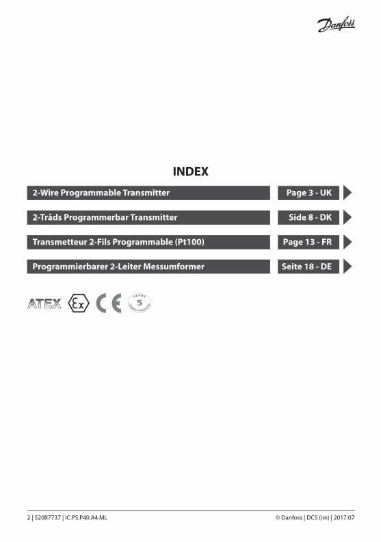
INDEX
2-Wire Programmable Transmitter Page 3 - UK
2-Tråds Programmerbar Transmitter Side 8 - DK
Transmetteur 2-Fils Programmable (Pt100) Page 13 - FR
Programmierbarer 2-Leiter Messumformer Seite 18 - DE
© Danfoss | DCS (im) | 2017.07 IC.PS.P40.A4.ML | 520B7737 | 3
CONTENTS
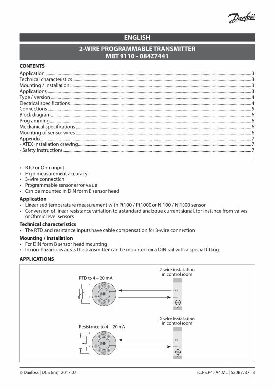
• RTD or Ohm input• High measurement accuracy• 3-wire connection• Programmable sensor error value• Can be mounted in DIN form B sensor headApplication• Linearised temperature measurement with Pt100 / Pt1000 or Ni100 / Ni1000 sensor• Conversion of linear resistance variation to a standard analogue current signal, for instance from valves or Ohmic level sensorsTechnical characteristics• The RTD and resistance inputs have cable compensation for 3-wire connectionMounting / installation• For DIN form B sensor head mounting• In non-hazardous areas the transmitter can be mounted on a DIN rail with a special fitting
2-WIRE PROGRAMMABLE TRANSMITTER MBT 9110 - 084Z7441
ENGLISH
V+
+-
V+
+-
mA
RTD to 4 – 20 mA
2-wire installationin control room
mA
2-wire installationin control room
Resistance to 4 – 20 mA
APPLICATIONS
Application ..............................................................................................................................................................................................3Technical characteristics .....................................................................................................................................................................3Mounting / installation .......................................................................................................................................................................3Applications ............................................................................................................................................................................................3Type / version .........................................................................................................................................................................................4Electrical specifications .......................................................................................................................................................................4Connections ............................................................................................................................................................................................5Block diagram .........................................................................................................................................................................................6Programming ..........................................................................................................................................................................................6Mechanical specifications ..................................................................................................................................................................6Mounting of sensor wires ..................................................................................................................................................................6Appendix ..................................................................................................................................................................................................7- ATEX Installation drawing................................................................................................................................................................7- Safety instructions ..............................................................................................................................................................................7

© Danfoss | DCS (im) | 2017.074 | 520B7737 | IC.PS.P40.A4.ML
Specifications range -40 °C – 85 °C
Common specifications
Supply voltage, DCMBT 9110, 084Z7440 8 – 35 V
Standard ATEX, MBT 9110, 084Z7441 8 – 30 V
Internal consumption 25 mW – 0.8 W
Voltage drop 8 VDC
Warm-up time 5 min.
Communications interface Loop Link
Signal / noise ratio min. 60 dB
Response time (programmable) 0.33 – 60 s
Signal dynamics, input 19 bit
Signal dynamics, output 16 bit
Calibration temperature 20 – 28 °C
ELECTRICAL SPECIFICATIONS
TYPE MBT 9110
VERSIONStandard 084Z7440
Standard Atex 084Z7441
BASIC VALUESInput type Basic accuracy Temperature coefficient
RTD ≤ ± 0.3 °C ≤ ± 0.01 °C / °C
Lin.R ≤ ± 0.2 Ω ≤ ± 20 m Ω / °C
EMC immunity influence ≤ ± 0.5% of span
ELECTRICAL SPECIFICATIONS, INPUT RTD AND LINEAR RESISTANCE INPUT
RTD type Min. value Max. value Min. span Standard
Pt 100 -200 °C 850 °C 25 °C IEC 60751
Ni 100 -60 °C 250 °C 25 °C DIN 43760
Lin. R 0 Ω 10000 Ω 30 Ω –
Effect of supply voltage variation ≤ 0,005% of span / VDC
Vibration IEC 60068-2-6 Test FC
Lloyd’s specification no. 1 4 g / 2 – 100 Hz
Max. wire size 1 x 1.5 mm2 stranded wire
Humidity < 95% RH (non-cond.)
Dimensions ø44 x 20.2 mm
Tightness (enclosure / terminal) IP68 / IP00
Weight 50 g
Max. offset 50% of selec. max. value
Cable resistance per wire (max.) 10 Ω
Sensor current > 0.2 mA, < 0.4 mA
Effect of sensor cable resistance (3-wire) < 0.002 Ω / Ω
Sensor error detection Yes
GENERAL VALUESInput type Absolute accuracy Temperature coefficient
All ≤ ± 0.1% of span ≤ ± 0.01% of span / °C
ACCURACY, THE GREATER OF GENERAL AND BASIC VALUES

© Danfoss | DCS (im) | 2017.07 IC.PS.P40.A4.ML | 520B7737 | 5
OUTPUT CURRENT OUTPUT
SENSOR ERROR DETECTION
OBSERVED AUTHORITY REQUIREMENTS STANDARD
EEx approval MBT 9110, 084Z7441
Signal range 4 – 20 mA
Min. signal range 16 mA
Updating time 135 ms
Load resistance ≤ (Vsupply- 8) / 0.023 [Ω]
Load stability ≤ ±0.01% of span / 100 Ω
Programmable 3.5 – 23 mA
NAMUR NE43 Upscale 23 mA
NAMUR NE43 Downscale 3.5 mA
EMC 2004/108/EF Emission and immunity EN 61326-1
ATEX 94/9/EC
EN 60079-0, EN 60079-11
EN 60079-15, EN 60079-26
EN 61241-0, EN 61241-11
Of span = Of the presently selected range
KEMA 04ATEX1339II 1 G Ex ia IIC T4 or T6
II 1 D Ex iaD
Max. amb. temperature for T4 85 °C
Max. amb. temperature for T6 60 °C
ATEX, applicable in zone 0, 1, 2, 20, 21 or 22
ATEX Installation Drawing No. MBT 9110 084Z7441
CONNECTIONS
© Danfoss | DCS (im) | 2017.076 | 520B7737 | IC.PS.P40.A4.ML
1
2
*
L oopL ink
5909 - USB5905 - RS232
MBT 9110
File Product Input Output Communication Language Option 08:30:00
Pr etop 5331
Date: 2004-8.10
Serial No.: 043201594
Tag No.: PR electronics
Analog Input Analog Ouput
Input Type: Pt 100 DIN / IEC Output Type: 4 – 20 mA
Input Range: 0 – 500C Sensor error: Upscale
Connection: 3-wire
Cold junction comp: ---------
Response time: 1.00 sec
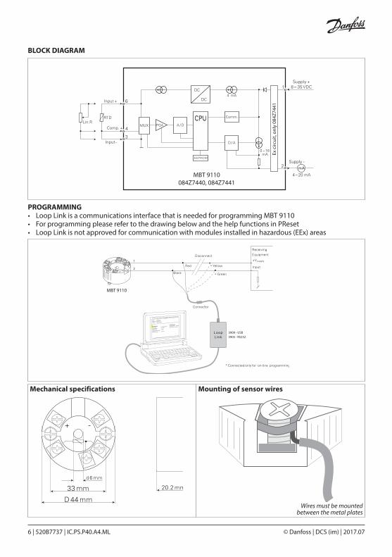
Wires must be mounted between the metal plates
Mechanical specifications
PROGRAMMING• Loop Link is a communications interface that is needed for programming MBT 9110• For programming please refer to the drawing below and the help functions in PReset• Loop Link is not approved for communication with modules installed in hazard ous (EEx) areas
Mounting of sensor wires
BLOCK DIAGRAM
Ex c
ircui
t, on
ly 0
84Z7
441
MBT 9110084Z7440, 084Z7441
–
–
–
© Danfoss | DCS (im) | 2017.07 IC.PS.P40.A4.ML | 520B7737 | 7
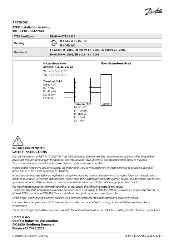
APPENDIXATEX Installation drawing MBT 9110 - 084Z7441
ATEX Certificate KEMA 04ATEX 1339
MarkingII 1 G Ex ia IIC T6 – T4
II 1 D Ex iaD
StandardsEN 60079-0 : 2006, EN 60079-11 : 2007, EN 60079-26 : 2007,
EN 61241-0 : 2006, EN 61241-11 : 2006
Hazardous area Zone: 0, 1, 2, 20, 21, 22T4: -40 ≤ Ta ≤ 85 °C T6: -40 ≤ Ta ≤ 60 °C
Non Hazardous Area
1
2
6
5
4
3
+
-
Barrier
Terminal: 3,4,6Uo: 27 VDCIo: 7 mAPo: 45 mWLo: 35 mHCo: 90 nF
Terminal: 1,2Ui: 30 VDCIi: 120 mAPi: 0.84 WLi: 10μHCi: 1.0nF
INSTALLATION NOTES SAFETY INSTRUCTIONSFor safe installation of MBT 9110 084Z 7441 the following must be observed. The module shall only be Installed by qualified personnel who are familiar with the national and international laws, directives and standards that apply to this area. Year of manufacture can be taken from the first two digits in the serial number.
In a potentially explosive gas atmosphere, the transmitter shall be mounted in an enclosure in order to provide a degree of protection of at least IP20 according to EN60529.
If the transmitter is installed in an explosive atmosphere requiring the use of equipment of category 1G and if the enclosure is made of aluminium, it must be installed such, that even in the event of rare incidents, ignition sources due to impact and friction, sparks are excluded; if the enclosure is made of non-metallic materials, electrostatic charging shall be avoided.
For installation in a potentially explosive dust atmosphere, the following instructions apply:The transmitter shall be mounted in a metal enclosure form B according to DIN43729 that is providing a degree of protection of at least IP6X according to EN60529, that is suitable for the application and correctly installed.
Cable entries and blanking elements shall be used that are suitable for the application and correctly installed.
For an ambient temperature ≥ 60 °C, heat resistant cables shall be used with a rating of at least 20 K above the ambient temperature.
The surface temperature of the enclosure is equal to the ambient temperature plus 20 K, for a dust layer with a thickness up to 5 mm.
Danfoss A/SDanfoss Industrial AutomationDK 6430 Nordborg DenmarkPhone +45 7488 2222

© Danfoss | DCS (im) | 2017.078 | 520B7737 | IC.PS.P40.A4.ML
INDHOLDSFORTEGNELSE
2-TRÅDS PROGRAMMERBAR TRANSMITTER MBT 9110 - 084Z7441
DANISH
APPLIKATIONER
• Indgang for RTD eller Ohm• Høj målenøjagtighed• 3-leder tilslutning• Programmerbar følerfejlsværdi• Kan monteres i DIN form B følerhoved Anvendelse• Temperaturlineariseret måling med Pt100...Pt1000 eller Ni100 / Ni1000 føler• Omsætning af lineær modstandsændring til standard analogt strømsignal, f.eks. fra ventiler eller ohmske niveaustaveTeknisk karakteristik• RTD- og modstandsindgangen har kabelkompensering for 3-leder tilslutningMontage / installation• Kan monteres i DIN form B følerhoved• I ikke-eksplosionsfarlige områder kan transmitteren monteres på en DIN-skinne med et specielt beslag
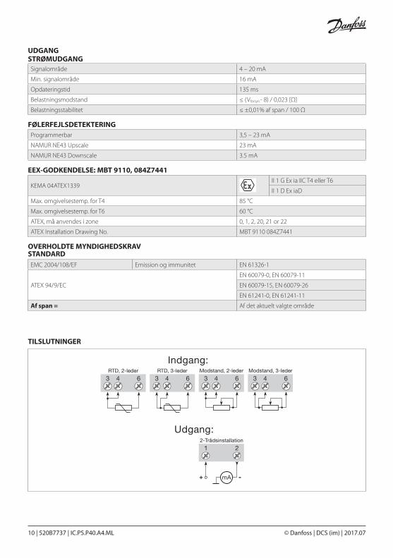
RTD til 4 – 20 mA
2-trådsinstallationi kontrolrum
2-trådsinstallationi kontrolrum
Modstand til 4 – 20 mA
Anvendelse ..............................................................................................................................................................................................8Teknisk karakteristik .............................................................................................................................................................................8Montage / installation .........................................................................................................................................................................8Applikationer ..........................................................................................................................................................................................8Typer / versioner ....................................................................................................................................................................................9Elektriske specifikationer ....................................................................................................................................................................9Tilslutninger ......................................................................................................................................................................................... 10Blokdiagram ......................................................................................................................................................................................... 11Programmering ................................................................................................................................................................................... 11Mekaniske specifikationer .............................................................................................................................................................. 11Montering af følerledninger ........................................................................................................................................................... 11Appendix ............................................................................................................................................................................................... 12- ATEX Installation drawing............................................................................................................................................................. 12 - Sikkerheds instruktion ................................................................................................................................................................... 12

© Danfoss | DCS (im) | 2017.07 IC.PS.P40.A4.ML | 520B7737 | 9
Specifikationsområde -40 °C – 85 °C
Fælles specifikationer
Forsyningsspænding DCMBT 9110, 084Z7440 8 – 35 V
Standard ATEX, MBT 9110, 084Z7441 8 – 30 V
Egetforbrug 25 mW – 0,8 W
Spændingsdrop 8 VDC
Opvarmningstid 5 min.
Kommunikationsinterface Loop Link
Signal- / støjforhold min. 60 dB
Reaktionstid (programmerbar) 0.33 – 60 s
Signaldynamik, indgang 19 bit
Signaldynamik, udgang 16 bit
Kalibreringstemperatur 20 – 28 °C
ELEKTRISKE SPECIFIKATIONER
TYPE MBT 9110
VERSIONStandard 084Z7440
Standard Atex 084Z7441
NØJAGTIGHED, STØRST AF GENERELLE OG BASISVÆRDIERGENERELLE VÆRDIER
Indgangstype Absolut nøjagtighed Temperatur-koefficient
Alle ≤ ± 0,1% of span ≤ ± 0,01% of span / °C
BASISVÆRDIERIndgangstype Basis-nøjagtighed Temperatur-koefficient
RTD ≤ ± 0,3 °C ≤ ± 0,01 °C / °C
Lin.R ≤ ± 0,2 Ω ≤ ± 20 m Ω / °C
EMC-immunitetspåvirkning ≤ ± 05% of span
ELEKTRISKE SPECIFIKATIONER INDGANG RTD- OG LINEÆR MOD STANDSINDGANG
RTD type Min. værdi Max. værdi Min. span Standard
Pt 100 -200 °C 850 °C 25 °C IEC 60751
Ni 100 -60 °C 250 °C 25 °C DIN 43760
Lin. R 0 Ω 10000 Ω 30 Ω –
Virkning af forsyningsspændingsændring ≤ 0,005% of span / VDC
Vibration IEC 60068-2-6 Test FC
Lloyd’s specifikation nr. 1 4 g / 2 – 100 Hz
Max. ledningskvadrat 1 x 1.5 mm2 stranded wire
Luftfugtighed < 95% RH (non-cond.)
Mål ø44 x 20.2 mm
Tæthedsgrad (hus / klemme) IP68 / IP00
Vægt 50 g
Max. nulpunktsforskydning (offset) 50% af valgt max. værdi
Kabelmodstand pr. leder (max.) 10 Ω
Følerstrøm > 0,2 mA, < 0,4 mA
Virkning af følerkabelmodstand (3-leder) > 0,002 Ω / Ω
Følerfejlsdetektering ja
© Danfoss | DCS (im) | 2017.0710 | 520B7737 | IC.PS.P40.A4.ML
UDGANG STRØMUDGANG
FØLERFEJLSDETEKTERING
OVERHOLDTE MYNDIGHEDSKRAV STANDARD
EEX-GODKENDELSE: MBT 9110, 084Z7441
Signalområde 4 – 20 mA
Min. signalområde 16 mA
Opdateringstid 135 ms
Belastningsmodstand ≤ (Vforsyn.- 8) / 0,023 [Ω]
Belastningsstabilitet ≤ ±0,01% af span / 100 Ω
Programmerbar 3,5 – 23 mA
NAMUR NE43 Upscale 23 mA
NAMUR NE43 Downscale 3.5 mA
EMC 2004/108/EF Emission og immunitet EN 61326-1
ATEX 94/9/EC
EN 60079-0, EN 60079-11
EN 60079-15, EN 60079-26
EN 61241-0, EN 61241-11
Af span = Af det aktuelt valgte område
KEMA 04ATEX1339II 1 G Ex ia IIC T4 eller T6
II 1 D Ex iaD
Max. omgivelsestemp. for T4 85 °C
Max. omgivelsestemp. for T6 60 °C
ATEX, må anvendes i zone 0, 1, 2, 20, 21 or 22
ATEX Installation Drawing No. MBT 9110 084Z7441
TILSLUTNINGER
© Danfoss | DCS (im) | 2017.07 IC.PS.P40.A4.ML | 520B7737 | 11
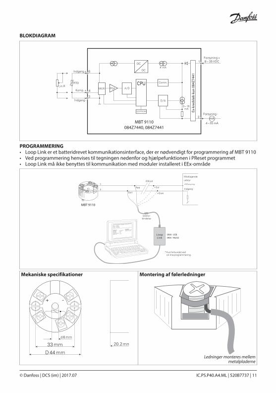
Ledninger monteres mellem metalpladerne
Mekaniske specifikationer
PROGRAMMERING• Loop Link er et batteridrevet kommunikationsinterface, der er nødvendigt for programmering af MBT 9110• Ved programmering henvises til tegningen nedenfor og hjælpefunktionen i PReset programmet• Loop Link må ikke benyttes til kommunikation med moduler installeret i EEx-område
Montering af følerledninger
BLOKDIAGRAM
MBT 9110 084Z7440, 084Z7441
Ex-k
reds
løb
kun
084Z
7441
–
–
–
1
2
*
L oopL ink
5909 - USB5905 - RS232
MBT 9110
File Product Input Output Communication Language Option 08:30:00
Pr etop 5331
Date: 2004-8.10
Serial No.: 043201594
Tag No.: PR electronics
Analog Input Analog Ouput
Input Type: Pt 100 DIN / IEC Output Type: 4 – 20 mA
Input Range: 0 – 50 0C Sensor error: Upscale
Connection: 3-wire
Cold junction comp: ---------
Response time: 1.00 sec

© Danfoss | DCS (im) | 2017.0712 | 520B7737 | IC.PS.P40.A4.ML
APPENDIXATEX Installation drawing MBT 9110 - 084Z7441
ATEX Certificate KEMA 04ATEX 1339
MarkingII 1 G Ex ia IIC T6 – T4
II 1 D Ex iaD
StandardsEN 60079-0 : 2006, EN 60079-11 : 2007, EN 60079-26 : 2007,
EN 61241-0 : 2006, EN 61241-11 : 2006
Hazardous area Zone: 0, 1, 2, 20, 21, 22T4: -40 ≤ Ta ≤ 85 °C T6: -40 ≤ Ta ≤ 60 °C
Non Hazardous Area
1
2
6
5
4
3
+
-
Barrier
Terminal: 3,4,6Uo: 27 VDCIo: 7 mAPo: 45 mWLo: 35 mHCo: 90 nF
Terminal: 1,2Ui: 30 VDCIi: 120 mAPi: 0.84 WLi: 10μHCi: 1.0nF
INSTALLATION NOTES SIKKERHEDSINSTRUKTIONBemærkninger til installering: For at gennemføre en sikker installering af MBT 9110 084Z7441 skal følgende overholdes. Modulet må kun installeres af kvalificeret personale, der er bekendt med gældende nationale og internationale love, direktiver og standarder inden for dette område. Produktionsåret fremgår af de første to cifre i serienummeret.
I en potentielt eksplosiv gasatmosfære skal transmitteren monteres i en kapsling, så man opnår en beskyttelsesgrad på min. IP20 i henhold til EN 60529.
Installeres transmitteren i en eksplosiv atmosfære, der kræver udstyr i kategori 1G, og hvis kapslingen er lavet af aluminium, skal den installeres således, at gnister fra antændelseskilder ved slag og friktion selv under usædvanlige omstændigheder holdes ude. Er kapslingen lavet af ikke-metalliske materialer, skal elektrostatisk opladning undgås.
Ved installering i en atmosfære med potentielt eksplosivt støv følges disse anvisninger:Transmitteren skal monteres i en metalkapsling form B i henhold til DIN 43729, der yder en beskyttelsesgrad på min. IP6X i henhold til EN 60529. Kapslingen skal være egnet til applikationen og installeret korrekt.
Der må kun anvendes kabelindgange og blindstik, der er egnet til applikationen og installeret korrekt.
Ved en omgivende temperatur på ≥ 60º C skal der anvendes varmebestandige kabler med en klassificering på mindst 20 K over den omgivende temperatur.
Kapslingens overfladetemperatur er lig med den omgivende temperatur plus 20 K ved et støvlag med en tykkelse på op til 5 mm.
Danfoss A/SDanfoss Industrial AutomationDK 6430 Nordborg DenmarkPhone +45 7488 2222
© Danfoss | DCS (im) | 2017.07 IC.PS.P40.A4.ML | 520B7737 | 13
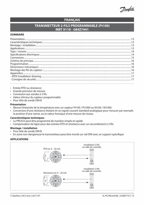
SOMMAIRE
• Entrée RTD ou résistance• Grande précision de mesure• Connexion aux sondes à 3 fils• Valeur d’erreur du capteur programmable• Pour tête de sonde DIN BPrésentation• Mesure linéarisée de la température avec un capteur Pt100 / Pt1000 ou Ni100 / Ni1000.• Conversion d’une résistance linéaire en un signal courant standard analogique pour mesurer par exemple la position d’une vanne, ou la valeur homique d’une mesure de niveauCaractéristiques techniques• Le PR5333 peut être programmé de manière simple et rapide• Compensation de ligne pour des entrées RTD et résistance avec un raccordement à 3 filsMontage / installation• Pour tête de sonde DIN B• En zone non-dangereuse le transmetteur peut être monté sur rail DIN avec un support spécifique
TRANSMETTEUR 2-FILS PROGRAMMABLE (Pt100) MBT 9110 - 084Z7441
FRANÇAIS
APPLICATIONS
V+
+-
V+
+-
mA
RTD en 4 – 20 mA
mA
Installation 2-�lsen salle de contrôle
Résistance en 4 – 20 mA
Installation 2-�lsen salle de contrôle
Présentation ..........................................................................................................................................................................................13Caractéristiques techniques ............................................................................................................................................................13Montage / installation .......................................................................................................................................................................13Applications ..........................................................................................................................................................................................13Type / version .......................................................................................................................................................................................14Spécifications électriques ................................................................................................................................................................14Connexions ............................................................................................................................................................................................15Schéma de principe............................................................................................................................................................................16Programmation ....................................................................................................................................................................................16Dimensions mécaniques ..................................................................................................................................................................16Montage des fils du capteur ...........................................................................................................................................................16Appendice ..............................................................................................................................................................................................17- ATEX Installation drawing..............................................................................................................................................................17 - Consigne de sécurité .......................................................................................................................................................................17
© Danfoss | DCS (im) | 2017.0714 | 520B7737 | IC.PS.P40.A4.ML
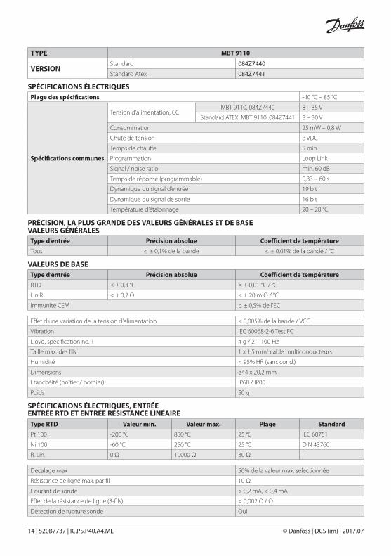
Plage des spécifications -40 °C – 85 °C
Spécifications communes
Tension d’alimentation, CCMBT 9110, 084Z7440 8 – 35 V
Standard ATEX, MBT 9110, 084Z7441 8 – 30 V
Consommation 25 mW – 0,8 W
Chute de tension 8 VDC
Temps de chauffe 5 min.
Programmation Loop Link
Signal / noise ratio min. 60 dB
Temps de réponse (programmable) 0,33 – 60 s
Dynamique du signal d’entrée 19 bit
Dynamique du signal de sortie 16 bit
Température d’étalonnage 20 – 28 °C
SPÉCIFICATIONS ÉLECTRIQUES
TYPE MBT 9110
VERSIONStandard 084Z7440
Standard Atex 084Z7441
VALEURS DE BASEType d’entrée Précision absolue Coefficient de température
RTD ≤ ± 0,3 °C ≤ ± 0,01 °C / °C
Lin.R ≤ ± 0,2 Ω ≤ ± 20 m Ω / °C
Immunité CEM ≤ ± 0,5% de l’EC
SPÉCIFICATIONS ÉLECTRIQUES, ENTRÉE ENTRÉE RTD ET ENTRÉE RÉSISTANCE LINÉAIRE
Type RTD Valeur min. Valeur max. Plage Standard
Pt 100 -200 °C 850 °C 25 °C IEC 60751
Ni 100 -60 °C 250 °C 25 °C DIN 43760
R. Lin. 0 Ω 10000 Ω 30 Ω –
Effet d’une variation de la tension d’alimentation ≤ 0,005% de la bande / VCC
Vibration IEC 60068-2-6 Test FC
Lloyd, spécification no. 1 4 g / 2 – 100 Hz
Taille max. des fils 1 x 1,5 mm2 càble multiconducteurs
Humidité < 95% HR (sans cond.)
Dimensions ø44 x 20,2 mm
Etanchéité (boîtier / bornier) IP68 / IP00
Poids 50 g
Décalage max 50% de la valeur max. sélectionnée
Résistance de ligne max. par fil 10 Ω
Courant de sonde > 0,2 mA, < 0,4 mA
Effet de la résistance de ligne (3-fils) < 0,002 Ω / Ω
Détection de rupture sonde Oui
VALEURS GÉNÉRALESType d’entrée Précision absolue Coefficient de température
Tous ≤ ± 0,1% de la bande ≤ ± 0,01% de la bande / °C
PRÉCISION, LA PLUS GRANDE DES VALEURS GÉNÉRALES ET DE BASE
© Danfoss | DCS (im) | 2017.07 IC.PS.P40.A4.ML | 520B7737 | 15
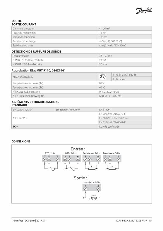
SORTIE SORTIE COURANT
DÉTECTION DE RUPTURE DE SONDE
AGRÉMENTS ET HOMOLOGATIONS STANDARD
Approbation EEx: MBT 9110, 084Z7441
Gamme de mesure 4 – 20 mA
Plage de mesure min. 16 mA
Temps de scrutation 135 ms
Résistance de charge ≤ (Valim.- 8) / 0,023 [Ω]
Stabilité de charge ≤ ±0,01% de l’EC / 100 Ω
Programmable 3,5 – 23 mA
NAMUR NE43 Haut d’échelle 23 mA
NAMUR NE43 Bas d’échelle 3,5 mA
EMC 2004/108/EF Emission et immunité EN 61326-1
ATEX 94/9/EC
EN 60079-0, EN 60079-11
EN 60079-15, EN 60079-26
EN 61241-0, EN 61241-11
EC = Echelle configurée
KEMA 04ATEX1339II 1 G Ex ia IIC T4 ou T6
II 1 D Ex iaD
Température amb. max. (T4) 85 °C
Température amb. max. (T6) 60 °C
ATEX, applicable en zone 0, 1, 2, 20, 21 or 22
ATEX Installation Drawing No. MBT 9110 - 084Z7441
CONNEXIONS
© Danfoss | DCS (im) | 2017.0716 | 520B7737 | IC.PS.P40.A4.ML
Les fils doivent être montés entre les plaques métalliques
Dimensions mécaniques
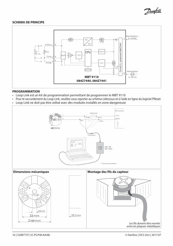
PROGRAMMATION• Loop Link est un kit de programmation permettant de programmer le MBT 9110• Pour le raccordement du Loop Link, veuillez vous reporter au schéma cidessous et à l’aide en ligne du logiciel PReset• Loop Link ne doit pas être utilisé avec des modules installés en zone dangereuse
Montage des fils du capteur
SCHEMA DE PRINCIPE
Circ
uit S
.I., s
eule
men
t 084
Z744
1
MBT 9110084Z7440, 084Z7441
–
–
–
VCC
1
2
*
L oopL ink
5909 - USB5905 - RS232
MBT 9110
File Product Input Output Communication Language Option 08:30:00
Pr etop 5331
Date: 2004-8.10
Serial No.: 043201594
Tag No.: PR electronics
Analog Input Analog Ouput
Input Type: Pt 100 DIN / IEC Output Type: 4 – 20 mA
Input Range: 0 – 50 0C Sensor error: Upscale
Connection: 3-wire
Cold junction comp: ---------
Response time: 1.00 sec
© Danfoss | DCS (im) | 2017.07 IC.PS.P40.A4.ML | 520B7737 | 17
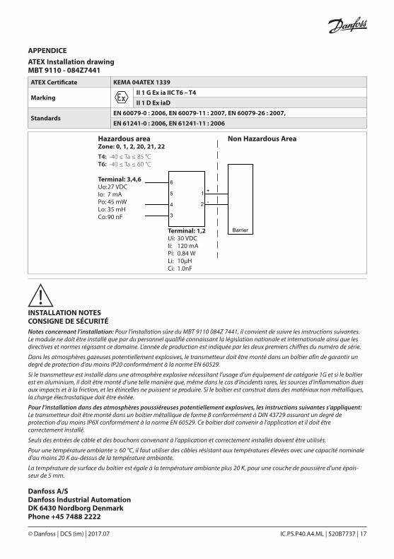
APPENDICEATEX Installation drawing MBT 9110 - 084Z7441
ATEX Certificate KEMA 04ATEX 1339
MarkingII 1 G Ex ia IIC T6 – T4
II 1 D Ex iaD
StandardsEN 60079-0 : 2006, EN 60079-11 : 2007, EN 60079-26 : 2007,
EN 61241-0 : 2006, EN 61241-11 : 2006
Hazardous area Zone: 0, 1, 2, 20, 21, 22T4: -40 ≤ Ta ≤ 85 °C T6: -40 ≤ Ta ≤ 60 °C
Non Hazardous Area
1
2
6
5
4
3
+
-
Barrier
Terminal: 3,4,6Uo: 27 VDCIo: 7 mAPo: 45 mWLo: 35 mHCo: 90 nF
Terminal: 1,2Ui: 30 VDCIi: 120 mAPi: 0.84 WLi: 10μHCi: 1.0nF
INSTALLATION NOTES CONSIGNE DE SÉCURITÉNotes concernant l’installation: Pour l’installation sûre du MBT 9110 084Z 7441, il convient de suivre les instructions suivantes. Le module ne doit être installé que par du personnel qualifié connaissant la législation nationale et internationale ainsi que les directives et normes régissant ce domaine. L’année de production est indiquée par les deux premiers chiffres du numéro de série.
Dans les atmosphères gazeuses potentiellement explosives, le transmetteur doit être monté dans un boîtier afin de garantir un degré de protection d’au moins IP20 conformément à la norme EN 60529.
Si le transmetteur est installé dans une atmosphère explosive nécessitant l’usage d’un équipement de catégorie 1G et si le boîtier est en aluminium, il doit être monté d’une telle manière que, même dans le cas d’incidents rares, les sources d’inflammation dues aux impacts et à la friction, et les étincelles ne puissent se produire. Si le boîtier est construit dans des matériaux non métalliques, la charge électrostatique doit être évitée.
Pour l’installation dans des atmosphères poussiéreuses potentiellement explosives, les instructions suivantes s’appliquent:Le transmetteur doit être monté dans un boîtier métallique de forme B conformément à DIN 43729 assurant un degré de protection d’au moins IP6X conformément à la norme EN 60529. Ce boîtier doit convenir à l’application et il doit être correctement installé.
Seuls des entrées de câble et des bouchons convenant à l’application et correctement installés doivent être utilisés.
Pour une température ambiante ≥ 60 °C, il faut utiliser des câbles résistant aux températures élevées avec une capacité nominale d’au moins 20 K au-dessus de la température ambiante.
La température de surface du boîtier est égale à la température ambiante plus 20 K, pour une couche de poussière d’une épais-seur de 5 mm.
Danfoss A/SDanfoss Industrial AutomationDK 6430 Nordborg DenmarkPhone +45 7488 2222
© Danfoss | DCS (im) | 2017.0718 | 520B7737 | IC.PS.P40.A4.ML
INHALTSVERZEICHNIS
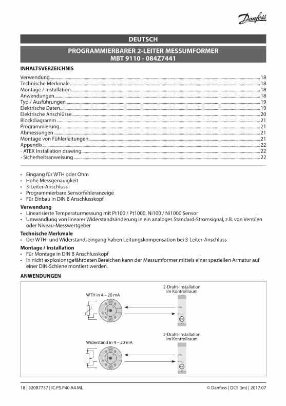
• Eingang für WTH oder Ohm• Hohe Messgenauigkeit• 3-Leiter-Anschluss• Programmierbare Sensorfehleranzeige• Für Einbau in DIN B AnschlusskopfVerwendung• Linearisierte Temperaturmessung mit Pt100 / Pt1000, Ni100 / Ni1000 Sensor• Umwandlung von linearer Widerstandsänderung in ein analoges Standard-Stromsignal, z.B. von Ventilen oder Niveau-MesswertgeberTechnische Merkmale• Der WTH- und Widerstandseingang haben Leitungskompensation bei 3-Leiter-AnschlussMontage / Installation• Für Montage in DIN B Anschlusskopf• In nicht explosionsgefährdeten Bereichen kann der Messumformer mittels einer speziellen Armatur auf einer DIN-Schiene montiert werden.
PROGRAMMIERBARER 2-LEITER MESSUMFORMER MBT 9110 - 084Z7441
DEUTSCH
ANWENDUNGEN
V+
+-
V+
+-
mA
WTH in 4 – 20 mA
2-Draht-Installationim Kontrollraum
2-Draht-Installationim Kontrollraum
mA
Widerstand in 4 – 20 mA
Verwendung..........................................................................................................................................................................................18Technische Merkmale ........................................................................................................................................................................18Montage / Installation .......................................................................................................................................................................18Anwendungen......................................................................................................................................................................................18Typ / Ausführungen ...........................................................................................................................................................................19Elektrische Daten.................................................................................................................................................................................19Elektrische Anschlüsse ......................................................................................................................................................................20Blockdiagramm ....................................................................................................................................................................................21Programmierung .................................................................................................................................................................................21Abmessungen ......................................................................................................................................................................................21Montage von Fühlerleitungen .......................................................................................................................................................21Appendix ................................................................................................................................................................................................22- ATEX Installation drawing..............................................................................................................................................................22- Sicherheitsanweisung .....................................................................................................................................................................22
© Danfoss | DCS (im) | 2017.07 IC.PS.P40.A4.ML | 520B7737 | 19
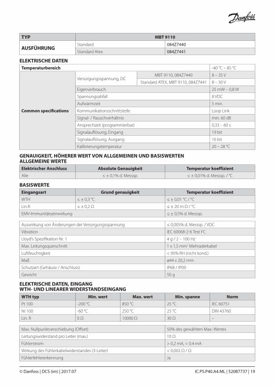
Temperaturbereich -40 °C – 85 °C
Common specifications
Versorgungsspannung, DCMBT 9110, 084Z7440 8 – 35 V
Standard ATEX, MBT 9110, 084Z7441 8 – 30 V
Eigenverbrauch 25 mW – 0,8 W
Spannungsabfall 8 VDC
Aufwärmzeit 5 min.
Kommunikationsschnittstelle Loop Link
Signal- / Rauschverhältnis min. 60 dB
Ansprechzeit (programmierbar) 0,33 – 60 s
Signalauflösung, Eingang 19 bit
Signalauflösung, Ausgang 16 bit
Kalibrierungstemperatur 20 – 28 °C
ELEKTRISCHE DATEN
TYP MBT 9110
AUSFÜHRUNGStandard 084Z7440
Standard Atex 084Z7441
BASISWERTEEingangsart Grund genauigkeit Temperatur koeffizient
WTH ≤ ± 0,3 °C ≤ ± 0,01 °C / °C
Lin.R ≤ ± 0,2 Ω ≤ ± 20 m Ω / °C
EMV-Immunitätseinwirkung ≤ ± 0,5% d. Messsp.
ELEKTRISCHE DATEN, EINGANG WTH- UND LINEARER WIDERSTANDSEINGANG
WTH typ Min. wert Max. wert Min. spanne Norm
Pt 100 -200 °C 850 °C 25 °C IEC 60751
Ni 100 -60 °C 250 °C 25 °C DIN 43760
Lin. R 0 Ω 10000 Ω 30 Ω –
Auswirkung von Änderungen der Versorgungsspannung ≤ 0,005% d. Messsp. / VDC
Vibration IEC 60068-2-6 Test FC
Lloyd’s Spezifikation Nr. 1 4 g / 2 – 100 Hz
Max. Leitungsquerschnitt 1 x 1,5 mm2 Mehraderkabel
Luftfeuchtigkeit < 95% RH (nicht kond.)
Maß ø44 x 20,2 mm
Schutzart (Gehäuse / Anschluss) IP68 / IP00
Gewicht 50 g
Max. Nullpunktverschiebung (Offset) 50% des gewählten Max.-Wertes
Leitungswiderstand pro Leiter (max.) 10 Ω
Fühlerstrom > 0,2 mA, < 0.4 mA
Wirkung des Fühlerkabelwiderstandes (3-Leiter) < 0,002 Ω / Ω
Fühlerfehlererkennung Ja
ALLGEMEINE WERTEElektrischer Anschluss Absolute Genauigkeit Temperatur koeffizient
Alle ≤ ± 0,1% d. Messsp. ≤ ± 0,01% d. Messsp. / °C
GENAUIGKEIT, HÖHERER WERT VON ALLGEMEINEN UND BASISWERTEN

© Danfoss | DCS (im) | 2017.0720 | 520B7737 | IC.PS.P40.A4.ML
AUSGANG STROMAUSGANG
FÜHLERFEHLERERKENNUNG
EINHALTUNG BEHÖRDLICHER AUFLAGEN NORM
EEx-Zulassung: MBT 9110, 084Z7441
Signalbereich 4 – 20 mA
Min. Signalbereich 16 mA
Aktualisierungszeit 135 ms
Belastungswiderstand ≤ (VVers.- 8) / 0,023 [Ω]
Belastungsstabilität ≤ ±0,01% d. Messsp. / 100 Ω
Programmierbar 3,5 – 23 mA
NAMUR NE43 aufsteuernd 23 mA
NAMUR NE43 zusteuernd 3,5 mA
EMC 2004/108/EF Emission und immunität EN 61326-1
ATEX 94/9/EC
EN 60079-0, EN 60079-11
EN 60079-15, EN 60079-26
EN 61241-0, EN 61241-11
d. Messspanne = der gewählten Messspanne
KEMA 04ATEX1339II 1 G Ex ia IIC T4 oder T6
II 1 D Ex iaD
Max. Umgebungstemp. für T4 85 °C
Max. Umgebungstemp. für T6 60 °C
ATEX, für Anwendung in Zone 0, 1, 2, 20, 21 or 22
ATEX Installation Drawing No. MBT 9110 084Z7441
ELEKTRISCHE ANSCHLÜSSE
2-Leiter-Installation

© Danfoss | DCS (im) | 2017.07 IC.PS.P40.A4.ML | 520B7737 | 21
Die Leitungen müssen zwischen den Metallplatten montiert werden
Abmessungen
PROGRAMMIERUNG• Loop Link ist eine batteriegespeiste Schnittstelle zur Programmierung des MBT 9110• Bezüglich Programmierung verweisen wir auf die nachfolgende Zeichnung und die “Hilfe”-Funktion im PReset-Programm• Loop Link darf nicht zur Kommunikation mit Modulen, die in EEx-gefährdeten Bereichen installiert sind, benutzt werden
Montage von Fühlerleitungen
BLOCKDIAGRAMM
MBT 9110084Z7440, 084Z7441
Ex-K
reis
lauf
, nur
084
Z744
1
–
–
–
1
2
*
L oopL ink
5909 - USB5905 - RS232
MBT 9110
File Product Input Output Communication Language Option 08:30:00
Pr etop 5331
Date: 2004-8.10
Serial No.: 043201594
Tag No.: PR electronics
Analog Input Analog Ouput
Input Type: Pt 100 DIN / IEC Output Type: 4 – 20 mA
Input Range: 0 – 500C Sensor error: Upscale
Connection: 3-wire
Cold junction comp: ---------
Response time: 1.00 sec
© Danfoss | DCS (im) | 2017.0722 | 520B7737 | IC.PS.P40.A4.ML
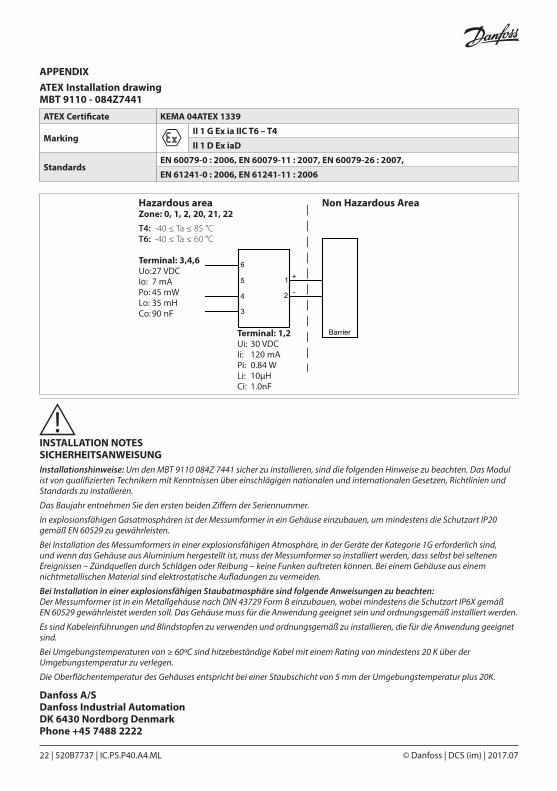
APPENDIXATEX Installation drawing MBT 9110 - 084Z7441
ATEX Certificate KEMA 04ATEX 1339
MarkingII 1 G Ex ia IIC T6 – T4
II 1 D Ex iaD
StandardsEN 60079-0 : 2006, EN 60079-11 : 2007, EN 60079-26 : 2007,
EN 61241-0 : 2006, EN 61241-11 : 2006
Hazardous area Zone: 0, 1, 2, 20, 21, 22T4: -40 ≤ Ta ≤ 85 °C T6: -40 ≤ Ta ≤ 60 °C
Non Hazardous Area
1
2
6
5
4
3
+
-
Barrier
Terminal: 3,4,6Uo: 27 VDCIo: 7 mAPo: 45 mWLo: 35 mHCo: 90 nF
Terminal: 1,2Ui: 30 VDCIi: 120 mAPi: 0.84 WLi: 10μHCi: 1.0nF
INSTALLATION NOTES SICHERHEITSANWEISUNGInstallationshinweise: Um den MBT 9110 084Z 7441 sicher zu installieren, sind die folgenden Hinweise zu beachten. Das Modul ist von qualifizierten Technikern mit Kenntnissen über einschlägigen nationalen und internationalen Gesetzen, Richtlinien und Standards zu installieren.
Das Baujahr entnehmen Sie den ersten beiden Ziffern der Seriennummer.
In explosionsfähigen Gasatmosphären ist der Messumformer in ein Gehäuse einzubauen, um mindestens die Schutzart IP20 gemäß EN 60529 zu gewährleisten.
Bei Installation des Messumformers in einer explosionsfähigen Atmosphäre, in der Geräte der Kategorie 1G erforderlich sind, und wenn das Gehäuse aus Aluminium hergestellt ist, muss der Messumformer so installiert werden, dass selbst bei seltenen Ereignissen – Zündquellen durch Schlägen oder Reibung – keine Funken auftreten können. Bei einem Gehäuse aus einem nichtmetallischen Material sind elektrostatische Aufladungen zu vermeiden.
Bei Installation in einer explosionsfähigen Staubatmosphäre sind folgende Anweisungen zu beachten: Der Messumformer ist in ein Metallgehäuse nach DIN 43729 Form B einzubauen, wobei mindestens die Schutzart IP6X gemäß EN 60529 gewährleistet werden soll. Das Gehäuse muss für die Anwendung geeignet sein und ordnungsgemäß installiert werden.
Es sind Kabeleinführungen und Blindstopfen zu verwenden und ordnungsgemäß zu installieren, die für die Anwendung geeignet sind.
Bei Umgebungstemperaturen von ≥ 60ºC sind hitzebeständige Kabel mit einem Rating von mindestens 20 K über der Umgebungstemperatur zu verlegen.
Die Oberflächentemperatur des Gehäuses entspricht bei einer Staubschicht von 5 mm der Umgebungstemperatur plus 20K.
Danfoss A/SDanfoss Industrial AutomationDK 6430 Nordborg DenmarkPhone +45 7488 2222

© Danfoss | DCS (im) | 2017.07 IC.PS.P40.A4.ML | 520B7737 | 23

© Danfoss | DCS (im) | 2017.07 IC.PS.P40.A4.ML | 520B7737 | 24