เซ็นเซอร์ และ ทรานสดิวเซอร์...• เคร องม อวดอ ณหภ ม (Temperature Transducer) • เคร องม

Temperature Transducer Trainer ST2302
Operating Manual Ver 1.2
An ISO 9001 : 2000 company
94, Electronic Complex, Pardeshipura Indore - 452 010 India Tel : 91-731 4211100 Fax : 91-731-2555643 e mail : [email protected] Websites: www.caddo.bz www.scientech.bz Toll free : 1800-103-5050 Web: www.scientech.bz

ST2302
Scientech Technologies Pvt. Ltd. 2
Temperature Transducers Trainer

ST2302
Scientech Technologies Pvt. Ltd. 3
ST2302 Table of Contents
1. Safety Instructions 4 2. Introduction 5
3. Features 6 4. Technical Specifications 7
5. Theory 8 I. Introduction to Transducers and Instrumentation 8
II. Reasons of using Transducers 9 III. Classification of Transducers 11
IV. Selection of a Transducer 17 V. Characteristics of Transducer 18
VI. Summary of Factors influencing the choice of Transducers 20 VII. Temperature Transducer 21
6. Recommended Testing Instruments for Experimentation 38
• Experiment 1 39 Characteristics of IC Temperature Sensor
• Experiment 2 41 Characteristics of Platinum RTD
• Experiment 3 45 Characteristics of NTC Thermistor
• Experiment 4 48 Characteristics of NTC Bridge Circuit
• Experiment 5 51 Characteristics of K type Thermocouple
• Experiment 6 55 Temperature controlled Alarm System (1 NTC)
• Experiment 7 57 Temperature controlled Alarm System (Bridge NTC)
7. FAQ 60
8. Glossary of Terms (Transducers) 64 9. Warranty 65
10. List of Accessories 65

ST2302
Scientech Technologies Pvt. Ltd. 4
Safety Instructions Read the following safety instructions carefully before operating the instrument. To avoid any personal injury or damage to the instrument or any product connected to it.
Do not operate the instrument if suspect any damage to it. The instrument should be serviced by qualified personnel only. For your safety: Use proper Mains cord : Use only the mains cord designed for this instrument.
Ensure that the mains cord is suitable for your country.
Ground the Instrument : This instrument is grounded through the protective earth conductor of the mains cord. To avoid electric shock the grounding conductor must be connected to the earth ground. Before making connections to the input terminals, ensure that the instrument is properly grounded.
Observe Terminal Ratings : To avoid fire or shock hazards, observe all ratings and marks on the instrument.
Use only the proper Fuse : Use the fuse type and rating specified for this instrument.
Use in proper Atmosphere : Please refer to operating conditions given in the manual.
1. Do not operate in wet / damp conditions. 2. Do not operate in an explosive atmosphere. 3. Keep the product dust free, clean and dry.

ST2302
Scientech Technologies Pvt. Ltd. 5
Introduction

ST2302
Scientech Technologies Pvt. Ltd. 6
Features • A Self Contained Trainer.
• Covers Fundamental Characteristics of 4 different Temperature Transducers.
• On board Signal Conditioning Circuitry.
• Built in DC Power Supply.
• Functional Blocks indicated On Board Mimic.
• Fully Documented student work book and Operating Manual.
• Compact Size.

ST2302
Scientech Technologies Pvt. Ltd. 7
Technical Specifications Transducers : 4 Nos.
1. N.T.C. thermistor 2. Platinum RTD
3. Type K thermocouple
4. IC Temperature Sensor LM 335
Heating Elements : Wire wound resistance 47Ω, 7 W Input Circuits : 1. 10 Turn Potentiometer
2. Wire wound potentiometer 3. Slide potentiometer
Signal Conditioning Circuitry : 1. X 100 amplifier 2. Instrumentation amplifier
3. Comparator 4. DC Amplifier
5. Electronic switch Output Circuit : 1. Relay
2. Buzzer Power Supply : 230 V +/- 10%, 50 Hz
Interconnections : 2 mm banana sockets Dimensions (mm) : W420 x H100 x D255
Weight : 3 Kgs. (approximately)

ST2302
Scientech Technologies Pvt. Ltd. 8
Theory Introduction to Transducers and Instrumentation
An Electronic Instrumentation system generally consists of three major elements: 1. Input Device ( Transducers or sensors )
2. Signal Conditioning or Processing Circuitry 3. Output Device (Display)
Figure 1
The input device receives the quantity under measurement and delivers the proportional electrical signal to the signal conditioning circuitry, where the signal is amplified, filtered or otherwise modified into a format which is acceptable to the output device. The output device may be indicating meter, an oscilloscope or a recorder for a visual display. The input quantity may be electrical or non-electrical. Non-electrical quantities include process variables like temperature, pressure & flow rate which are widely employed in process and product plants. The electrical quantities include current, voltage, resistance, inductance, capacitance, frequency, phase angle, power and magnetic quantities like flux, flux density and reluctance etc.
The optical quantity includes intensity of light falling on the device which converts it into electrical output. In order to use electrical techniques for measurement of all these quantities, we require a primary detection device called transducer. One definition states "a transducer is a device which, when actuated by energy in one transmission system supplies energy in the same form or in another form to a second transmission system ".
In order to extract information from mechanical system only mechanical displacement or velocity can be used. Hence, most of mechanical measurements firstly convert it into displacement or velocity and then transducers convert mechanical force or displacement into an electrical signal. These devices which convert physical quantities to electrical signal form a very large group of important transducers. Thus, transducer may be redefined as a device which converts a physical quantity into an electrical signal. The figure 2 shows generalized block diagram of measurement system.

ST2302
Scientech Technologies Pvt. Ltd. 9
Figure 2
Reasons of using Transducers: 1. They convert physical quantities into electrical output. 2. The signal conditioning becomes very easy.
3. The mass - inertia effects are minimized. In fact when dealing with electrical or electronic signals, the inertia effects are due to electrons which have negligible mass. In many situations we do not come across mass or inertia problems at all.
4. The effects of friction are minimized.
5. The electrical & electronic systems can be controlled with a very small power level.
6. The electrical output can be easily used, transmitted and processed for the purpose of measurement.
7. Telemetry or remote indications of recording is an important part of modem day instrumentation technology and this completely eliminates the data transmission through mechanical means and hence electrical and electronic principles have to be employed for those conditions.
8. The data can be stored and used for process control with the help of digital computers.
When the definition of transducer is confined to a device that covers the entire detectors transducer stage, whenever the transducer converts a non- electrical quantity into an analogous electrical signal, the transducer may be thought of consisting of two important & closely related part viz.
1. Sensing Element 2. Transduction Element

ST2302
Scientech Technologies Pvt. Ltd. 10
a. Sensing or detector element : The sensor senses the condition, state or value of the process variable and produces an output which reflects this condition, state or value. It is a part of a transducer which responds to physical phenomenon or a change in physical phenomenon. The response of the sensing element must be closely related to the physical phenomenon.
Figure 3
b. Transduction element : The transducer transforms the energy of the process variable to an output of some other energy which is able to operate some control device. A transduction element transforms the output of a sensing element to an electrical output. The transduction element in a way acts as a secondary transducer. Transducers can be classified according to their application, method of energy conversion, nature of output signal and so on. All these classifications usually result in overlapping areas, a sharp distinction between and classification types of transducers is difficult; however they may be classified on basis of:

ST2302
Scientech Technologies Pvt. Ltd. 11
Classification of Transducers: Transducers are classified on the basis of energy used which is shown in figure 4:
Types of energy form
Figure 4 i. Principle of Transduction used :
Transducers can be classified as the basis of principle of transduction as resistive, inductive, capacitive etc. depending on how they convert the input quantity into resistance, inductance and capacitance respectively.
Resistive transducer
Figure 5
2
1 2o T
RV VR R
=+

ST2302
Scientech Technologies Pvt. Ltd. 12
Change in displacement provides change in resistance & therefore provides the change in output voltage which is directly proportional to the change in displacement.
Inductive Transducer
Figure 6 Change in displacement provides change in flux linkage & therefore provides the change in output voltage on secondary winding which is directly proportional to the change in displacement.
Capacitive Transducer
Figure 7
o ACd
εε=
ε = dielectric constant
εo = 8.854 x 1o-12, in farad per meter A = the area of the plate, in square meter
d = the plate spacing in meters
ST2302
Scientech Technologies Pvt. Ltd. 13
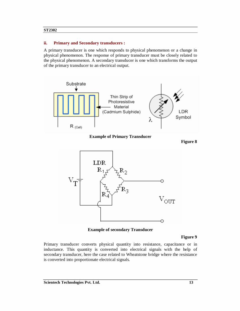
ii. Primary and Secondary transducers : A primary transducer is one which responds to physical phenomenon or a change in physical phenomenon. The response of primary transducer must be closely related to the physical phenomenon. A secondary transducer is one which transforms the output of the primary transducer to an electrical output.
Example of Primary Transducer
Figure 8
Example of secondary Transducer
Figure 9 Primary transducer converts physical quantity into resistance, capacitance or in inductance. This quantity is converted into electrical signals with the help of secondary transducer, here the case related to Wheatstone bridge where the resistance is converted into proportionate electrical signals.

ST2302
Scientech Technologies Pvt. Ltd. 14
iii. Passive & Active Transducers : Passive transducers derive the power required for transduction from an auxiliary power source. They also derive part of the power required for conversion from the physical quantity under measurement e.g. Potentiometer. Such transducers cannot work in the absence of external power. Active transducers are those which do not require an auxiliary power source to produce their output. Since, they develop their own voltage or current output. The energy required for production of output signal is obtained from physical quantity being measured.
Sun Light
Example of active transducer Figure 10
Active transducer does not require external source of power supply for converting one form of energy to other form of energy. Solar cell receives the sun light and directly converts it into electrical signals.
Example of Passive transducer
Figure 11 Passive transducer requires external source of power supply for converting one form of energy to other form of energy. Photo transistor requires the biasing for converting light energy in to electrical signals. Biasing is one type of external source of power supply.

ST2302
Scientech Technologies Pvt. Ltd. 15
iv. Analog & Digital Transducer : Analog transducers convert input quantity into an analog output which is a continuous function of time. Digital transducers convert the input quantity into an electrical output which is in the form of pulses.
Example of digital transducer
Figure 12
Example of analog transducer
Figure 13 v. Transducers & Inverse transducers : Transducers can be broadly defined as a device which converts a non electrical quantity into an electrical quantity. An inverse transducer is a device which converts an electrical quantity into a non electrical quantity. It is a precision actuator which has an electrical input and allows non-electrical output. Many data indicating and recording devices are inverse transducers. However, such devices which include instruments, pen recorders, oscilloscopes that convert the electrical signals to a mechanical movement are placed at the output stage (data presentation stage). The more useful application of inverse transducer is in feedback measuring systems.

ST2302
Scientech Technologies Pvt. Ltd. 16
Example of Transducer
Figure 14
Example of Inverse Transducer
Figure 15

ST2302
Scientech Technologies Pvt. Ltd. 17
Selection of a Transducer: In a measurement system the transducer is the input element with the critical function of transuding some physical quantity to a proportional electrical signal Selection of the appropriate transducer is therefore the first & perhaps most important step in obtaining accurate results. A number of elementary questions asked before a transducer can be selected.
1. What is the physical quantity to be measured? 2. Which transducer principal can best be used to measure this quantity?
3. What accuracy is required for this measurement? The first question can be answered by determining the type and range of the physical quantity. An appropriate answer to the second question requires input, output transfer characteristics of the transducer to be compatible with the recording or measurement system. In most cases these two questions can be answered readily, implying that the proper transducer is selected by the addition of an accuracy tolerance. In practice this is rarely possible due to the complexity of the various transducer parameters that affect the accuracy. The accuracy requirement of the total system determines the degree to which individual factors contributing to accuracy must be considered. 1. Fundamental transducer parameters
Type and range of measurement, sensitivity, excitation.
2. Physical Conditions : Mechanical & electrical connections, mounting provisions, corrosion resistance.
3. Ambient Conditions : Non-Linearity effects, Hysterisis effects, Frequency response resolution.
4. Environmental Conditions : Temperature effects, Acceleration, Shock & Vibration.
5. Compatibility of the associated equipment : Zero balance provisions, Sensitivity tolerance Impedance matching, Insulation resistance etc.
The total measurement error in a transducer activated system may be reduced to fall within the required accuracy range by the following techniques: 1. Using in place system calibration with corrections performed in the data
reduction. 2. Simultaneously monitoring the environment and correcting the data accordingly.
3. Artificially controlling the environment to minimize possible errors.

ST2302
Scientech Technologies Pvt. Ltd. 18
Characteristics of Transducer: When choosing a transducer for any application, the input, transfer & output characteristics have to be taken into account.
2. Input characteristics : This determines the input quantity the transducer is going to measure and its operating range. The useful operating range may be a decisive factor in selection of a transducer for a particular application. The upper limit is decided by the transducer capabilities while the lower limit of range is normally determined by the transducer error or by the unavoidable noise originating in the transducer. In fact the transducer should maintain a good resolution throughout its operating range. Ideally a transducer should have no loading effect in the input quantity being measured. The magnitude of loading effects can be expressed in terms of force, power or energy extracted from the quantity under measurement. For working of the transducers therefore, the transducer that is selected for a particular application should ideally extract no force, power or energy from the quantity under measurement in orders that later is measured correctly.
3. Transfer Characteristics : They require attention of three separate elements viz. a. Transfer function,
b. Error, c. Response of transducer to environmental influences.
i. Transfer function : It defines relationship between the input quantity and the output.
q0 = f (qi) q0 = output of transducer qi = input of transducer
ii. Error : The errors in transducers occur because they do not follow in many situations the input and output relationship given by
q0 = f (qi) Any departure from above relationship results in errors.
iii. Transducer response to environmental errors : This is of great importance and is often given insufficient attention when choosing the best transducer for a particular measurement. This gives rise to results that are not as accurate as expected, or, worse results that are the performance of the transducer is fully defined by its transfer function and errors, provided that the transducer is in

ST2302
Scientech Technologies Pvt. Ltd. 19
constant environment and not subjected to any disturbances like stray electromagnetic & electrostatic fields, mechanical shocks and vibrations temperature changes, pressure & humidity changes, changes in supply voltage and improper mechanical mountings. If transducers are subjected to above environmental disturbances which they are, precautions are taken, so that changes in transfer function and resulting errors do not occur. Therefore, the transducer selected must be guarded against the interfering and modifying inputs.
3. Output Characteristics : The three conditions in the output characteristics which should be considered:
a. Type of electrical output, b. Output Impedance,
c. Useful Range.
i. Type of Electrical Output : The types of electrical output available from the transducers may be a voltage, current, impedance or a time function of these amplitudes. These output quantities may or may not be acceptable to the latter stages of the instrumentation system. They may have to be manipulated i.e. their magnitudes changed or they may have to be changed in their format by signal conditioning equipment so as to make them drive the subsequent stages of instrumentation system.
ii. Output Impedance : The output impedance Zo of a transducer determines to the extent the subsequent stages of instrumentation is loaded ideally the value of output impedance should be zero if no loading effects are there on the subsequent stage. However, the output impedance cannot be made equal to zero & therefore its value should be kept as low as possible to minimize the loading effects.
The output impedance determines the amount of power that can be fed to the succeeding stages of the instrumentation system for a given output signal level.
iii. Useful Output Range : The output range of a transducer is limited at the lower end by noise signal which may shroud the desired input signals. The upper limit is set by the maximum useful output level. The output range can be increased, in some cases, by the inclusion of amplifier in the transducer. However the inclusion of an amplifier also increases the noise level and therefore in such situations the amplifier may not be of any use at all.

ST2302
Scientech Technologies Pvt. Ltd. 20
Summary of Factors influencing the choice of Transducers: It will be realized that there are many ways for measurement of a physical quantity and in many cases, there is no best way. The transducers and the method used may depend upon the instrumentation already available and also on the experience of the user. Unfortunately most transducers are not sensitive to just one quantity of measurements are to be made under conditions where there is likelihood of two or more input quantities influencing the transducer, it is desirable to select a transducer which is sensitive to the desirable quantity & insensitive to the unwanted quantity. If this is not possible, ways & measures should be found to eliminate or compensate for the effects of the unwanted input quantity. Following are some of the factors influencing the choice of a transducer for measurement of a physical quantity.
1. Operating Principle 2. Sensitivity
3. Operating Range
4. Accuracy
5. Cross Sensitivity 6. Errors
7. Transient & Frequency response 8. Loading Effects
9. Environmental Compatibility 10. Insensitivity to Unwanted Signals
11. Usage and Ruggedness 12. Electrical aspects
13. Stability & Reliability 14. Static Characteristics

ST2302
Scientech Technologies Pvt. Ltd. 21
Temperature Transducers: The most commonly used type of the entire sensor are those which detect Temperature or heat. These types of sensors vary from simple ON/OFF thermostatic devices which control a domestic hot water system to highly sensitive semiconductor types that can control complex process control plants. Temperature Sensors measure the amount of heat energy or even coldness within an object or system, and can "sense" or detect any physical change to that temperature.
There are many different types of Temperature Sensors available and all have different characteristics depending upon their actual application. Temperature sensors consist of two basic physical types:
• Contact Types - These types of temperature sensors are required to be in physical contact with the object being sensed and uses conduction to monitor changes in temperature. They can be used to detect solids, liquids or gases over a wide range of temperatures.
• Non-contact Types - These types of temperature sensors detect the Radiant Energy being transmitted from the object in the form of Infra-red radiation. They can be used with any solid or liquid that emits radiant energy.
The two basic types of contact or even non-contact temperature sensors can also be sub-divided into the following three groups of sensors, Electro-mechanical, Resistive and Electronic and all three types are discussed below.
Thermostat:
A thermostat are contact type electro-mechanical temperature sensors that basically consists of two different metals such as Nickel, Copper, Tungsten or Aluminum etc, that are bonded together to form a Bi-metallic strip. The different linear expansion rates of the two dissimilar metals produce a mechanical bending movement when the strip is subjected to heat. The bi-metallic strip or thermostat as it is more commonly called is used extensively to control hot water heating elements in boilers, furnaces, hot water storage tanks and also in vehicle radiator cooling systems.

ST2302
Scientech Technologies Pvt. Ltd. 22
Bi-metallic Thermostat:
Figure16
There are two main types of bi-metallic strips based mainly upon their movement when subjected to temperature changes, "Snap-action" types that produce an instantaneous "ON/OFF" or "OFF/ON" type snap action on the electrical contacts and the slower "Creep-action" types that gradually change their position as the temperature changes. Creeper types generally consist of a bi-metallic coil or spiral that unwinds or coils-up as the temperature changes. Generally, creeper type bi-metallic strips are more sensitive to temperature changes than the standard snap ON/OFF types as the strip is longer and thinner making them ideal for use in temperature gauges and dials etc.
One main disadvantage of the standard "Snap-action" type thermostats when used as a temperature sensor is that they have a large hysterisis range from when the electrical contacts open until when they close for example, set to 20oC but may not open until 22oC or close again until 18oC. So the range of temperature swing can be quite high. Commercially available Bi-metallic thermostats for home use do have temperature adjustment screws that allow for a desired set-point and even its hysterisis level to be pre-set and are available over a wide operating range.
The ST2302 Temperature transducers trainer deals with 4 temperature transducers viz. 1. Platinum RTD 2. K type Thermocouple. 3. N.T.C. Transmitter. 4. IC Temperature Sensor (LM335). The detail description of each type of Temperature Transducers is dealt with in the respective theory chapters

ST2302
Scientech Technologies Pvt. Ltd. 23
LM 335: Each of the three transducers described earlier, i.e. RTD, thermistor and thermocouples have some significant limitations, e.g. thermocouples have a low output signal which varies none linearly with temperature. Also, they need some form of reference compensation. RTD's are more linear than thermocouple but the change in their resistance is very small even for large change in input temperatures i.e. they have low sensitivity. Thermistor has high sensitivity but they exhibit highly non-linear resistance temperature characteristics.
For each of these transducers, electronic compensation circuits have to be used in order to overcome their shortcomings. Also additional circuitry may be needed to increase their voltage or current output. Usually this additional electronics circuitry takes the form of monolithic integrated circuits. Thus it requires combining temperature sensing element with signal conditioning electronics to produce single monolithic IC package. The one used in ST2302 is LM 335.
This is an IC containing 16 transistors 9 resistance and 2 capacitors contained in a transistor type package. It provides an output of 10mV/° K, measurements of output voltage therefore indicate the temperature directly in degrees Kelvin e.g. at a temperature of 20°C (293 °K) the output voltage will be 2.93V. Note: An LM335 unit is mounted on the type K thermocouple panel, external to the heated closure and fitted in a heat sink together with another type K thermocouple. Its output is available at the REF socket. The output form this can be used as an indication of the ambient temperature outside the heated enclosure. The IC Temperature Sensor is already connected as shown below:
Figure 17
RTD: The variation in resistance of a metal with variation in temperature is the basis of temperature measurement in a Platinum RTD. The metal generally used is platinum or tungsten. Platinum is especially suited for this purpose, as it can shows limited

ST2302
Scientech Technologies Pvt. Ltd. 24
susceptibility to contamination. All metals produce a positive change in resistance with temperature. This of course is the main function of an RTD. This implies a metal with high value of resistance should be used for RTD’s. The requirements of a conductor material to be used in RTD’s are:
1. The change in resistance of material per unit change in temperature should be as large as possible.
2. The material should have high value of resistance so that minimum volume of material is used for the construction of RTD.
3. The resistance of material should have continuous and stable relationship with temperature.
Resistance temperature detectors (RTDs), also called resistance thermometers, are temperature sensors that exploit the predictable change in electrical resistance of some materials with changing temperature.
Temperature Metal Resistance
The resistance ideally varies linearly with temperature. Platinum or tungsten wire is wound on a former to give a resistance in the range of 10K ohms depending on application. Tungsten is reserved for high temperature application as it is brittle and extremely difficult to work.
The construction of platinum RTD is as under:
Figure 18

ST2302
Scientech Technologies Pvt. Ltd. 25
To the first approximation, resistance variation with temperature is linear although more complex equations are used for greater accuracies. In fact standard calibration charts are available for different materials. The RTD used in ST2302 is of 100 Ohm at 0°C (Temperature coefficient = 0.385 ohms /°C).
Resistance vs Temperature Approximations: R(T) = approximation of resistance at temperature T R(T0) = resistance at temperature T0
αo = fractional change in resistance per degree of temperature at T0 ΔT = T - T0
Temperature V/S Resistance of various materials:
Figure 19
In the practical exercise you will connect the platinum RTD in series with a high resistance to a DC supply and measure the voltage drop across it. Due to the small variation of resistance, the current drop across transducer will be directly proportional to its resistance.
21]1)[()( TTTTTRTR oo <<∆+= α

ST2302
Scientech Technologies Pvt. Ltd. 26
The RTD consists of a thin film of platinum deposited on a ceramic substrate with gold contact-plates on each end.
The platinum resistance temperature detector is a highly stable and accurate sensor. The resistance increases linearly at 0.385 Ohm/°C. To develop a voltage a suitable resistance should be connected between output and +5V and the wire-wound potentiometer is recommended. The RTD is located in the transparent plastic heating compartment.
RTD – sensitivity:
• Sensitivity is shown by the value αo
Platinum – 0.004/ °C
Nickel – 0.005/ °C
• Thus, for a 100Ω platinum RTD, a change of only 0.4 Ω would be expected if the temperature is changed by 1°C
RTD – response time
• Generally 0.5 to 5 seconds or more
• The slowness of response is due principally to the slowness of thermal conductivity in bringing the device into thermal equilibrium with its environment.
Thermistor: Thermistor is a contraction of a term thermal resistor. Although positive temperature co-efficient (P.T.C) of unit exhibit an increase in the value of resistance with increase in temperature are available, most Thermistor have a negative temperature coefficient i.e. their resistance decreases with increase in temperature. In some materials the resistance of Thermistor at room temperature may decrease as much as 6% for 1°C rise in temperature. This high sensitivity to temperature change make the Thermistor extremely well suited to precision temperature measurement, control & compensation. Therefore, especially in lower temperatures range of -100°C to 300°C, or to detect very small changes in temperature which cannot be observed with an RTD or a thermocouple. Thermistor is composed of a sintered mixture of metallic oxides, such as Mn, Ni, Co, Cu, Fe, & U. Their resistance range from 0.5 Ω to 75MΩ and they are available in wide variety of shapes and sizes.
ST2302
Scientech Technologies Pvt. Ltd. 27
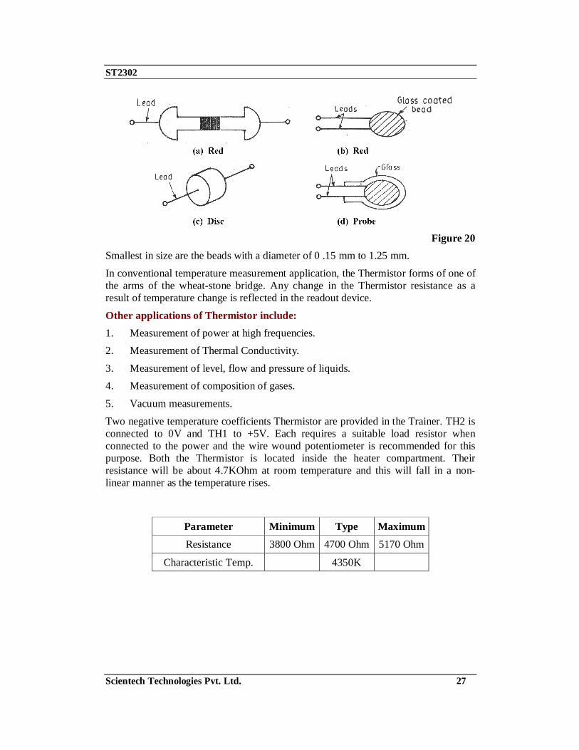
Figure 20
Smallest in size are the beads with a diameter of 0 .15 mm to 1.25 mm.
In conventional temperature measurement application, the Thermistor forms of one of the arms of the wheat-stone bridge. Any change in the Thermistor resistance as a result of temperature change is reflected in the readout device.
Other applications of Thermistor include: 1. Measurement of power at high frequencies. 2. Measurement of Thermal Conductivity.
3. Measurement of level, flow and pressure of liquids. 4. Measurement of composition of gases.
5. Vacuum measurements.
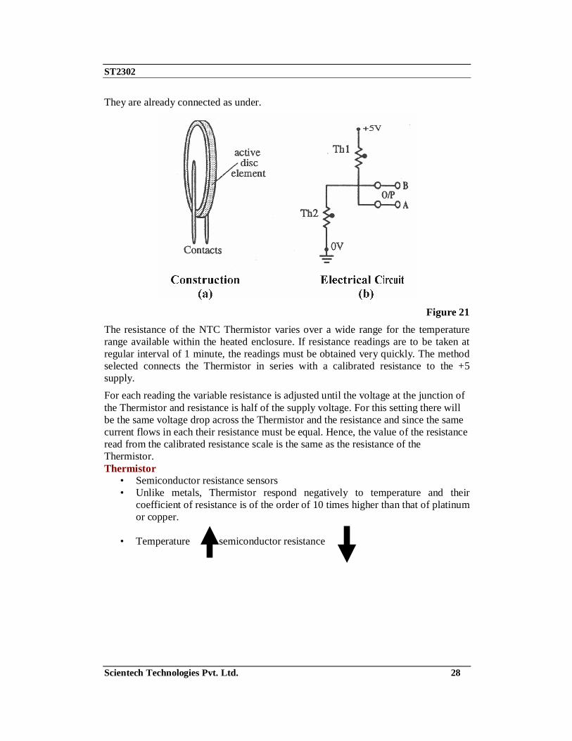
Two negative temperature coefficients Thermistor are provided in the Trainer. TH2 is connected to 0V and TH1 to +5V. Each requires a suitable load resistor when connected to the power and the wire wound potentiometer is recommended for this purpose. Both the Thermistor is located inside the heater compartment. Their resistance will be about 4.7KOhm at room temperature and this will fall in a non-linear manner as the temperature rises.
Parameter Minimum Type Maximum
Resistance 3800 Ohm 4700 Ohm 5170 Ohm
Characteristic Temp. 4350K
ST2302
Scientech Technologies Pvt. Ltd. 28
They are already connected as under.
Figure 21
The resistance of the NTC Thermistor varies over a wide range for the temperature range available within the heated enclosure. If resistance readings are to be taken at regular interval of 1 minute, the readings must be obtained very quickly. The method selected connects the Thermistor in series with a calibrated resistance to the +5 supply. For each reading the variable resistance is adjusted until the voltage at the junction of the Thermistor and resistance is half of the supply voltage. For this setting there will be the same voltage drop across the Thermistor and the resistance and since the same current flows in each their resistance must be equal. Hence, the value of the resistance read from the calibrated resistance scale is the same as the resistance of the Thermistor. Thermistor
• Semiconductor resistance sensors • Unlike metals, Thermistor respond negatively to temperature and their
coefficient of resistance is of the order of 10 times higher than that of platinum or copper.
• Temperature semiconductor resistance

ST2302
Scientech Technologies Pvt. Ltd. 29
Thermistor: resistance vs temperature
Thermistor resistance versus temperature is highly nonlinear and usually has a
negative slope
Figure 22 NTC Bridge circuit When used for alarm or protection circuits, two Thermistors would normally be used there being connected in a bridge circuit as shown in Figure 23.
Figure 23
The two resistances R have the same resistance as the 'cold' resistance of the thermistor. When cold, there will be no output across points A & B as the bridge will be balanced.
ST2302
Scientech Technologies Pvt. Ltd. 30
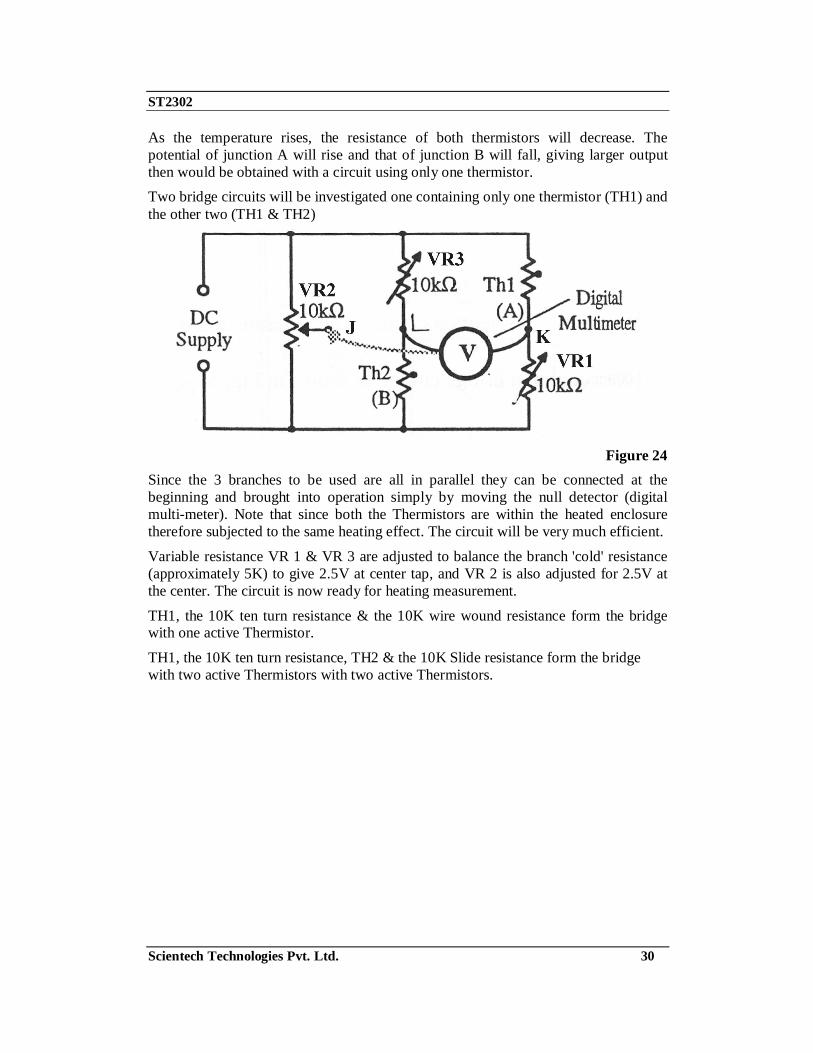
As the temperature rises, the resistance of both thermistors will decrease. The potential of junction A will rise and that of junction B will fall, giving larger output then would be obtained with a circuit using only one thermistor. Two bridge circuits will be investigated one containing only one thermistor (TH1) and the other two (TH1 & TH2)
Figure 24
Since the 3 branches to be used are all in parallel they can be connected at the beginning and brought into operation simply by moving the null detector (digital multi-meter). Note that since both the Thermistors are within the heated enclosure therefore subjected to the same heating effect. The circuit will be very much efficient.
Variable resistance VR 1 & VR 3 are adjusted to balance the branch 'cold' resistance (approximately 5K) to give 2.5V at center tap, and VR 2 is also adjusted for 2.5V at the center. The circuit is now ready for heating measurement.
TH1, the 10K ten turn resistance & the 10K wire wound resistance form the bridge with one active Thermistor.
TH1, the 10K ten turn resistance, TH2 & the 10K Slide resistance form the bridge with two active Thermistors with two active Thermistors.

ST2302
Scientech Technologies Pvt. Ltd. 31
Thermocouple: The Thermocouple is the most commonly used type of all the temperature sensing devices due to its simplicity, ease of use and their speed of response to changes in temperature, due mainly to their small size. Thermocouples also have the widest temperature range of all the temperature sensing devices from below -200oC to well over 2000oC. It basically consists of two junctions of dissimilar metals, such as copper and constantan that are welded or crimped together. One junction is kept at a constant temperature called the reference (Cold) junction, while the other the measuring (Hot) junction is used as the temperature sensor and this is shown below.
Figure 25 The principle of operation is that the junction of the two dissimilar metals produces a "thermo-electric" effect that produces a constant potential difference of only a few milli volts (mV) between and which changes as the temperature changes. If both the junctions are at the same temperature the potential difference across the two junctions is zero in other words, no voltage output. However, when the junctions are connected within a circuit and are both at different temperatures a voltage output will be detected relative to the difference in temperature between the two junctions. This voltage output will increase with temperature until the junction’s peak voltage level is reached and this is determined by the characteristics of the two metals used.
Thermocouples can be made from a variety of different materials enabling extreme temperatures of between -200oC to over +2000oC to be measured. With such a large choice of materials and temperature range, internationally accepted standards have been developed complete with thermocouple Colour codes to allow the user to choose the correct thermocouple sensor for a particular application. The British Colour code for standard thermocouples is given below.
ST2302
Scientech Technologies Pvt. Ltd. 32
The practical considerations of thermocouples:
The above theory of thermocouple operation has important practical implications that are well worth understanding:
1. A third metal may be introduced into a thermocouple circuit and have no impact, provided that both ends are at the same temperature. This means that the thermocouple measurement junction may be soldered, brazed or welded without affecting the thermocouple's calibration, as long as there is no net temperature gradient along the third metal.
Further, if the measuring circuit metal (usually copper) is different to that of the thermocouple, then provided the temperature of the two connecting terminals is the same and known, the reading will not be affected by the presence of copper.
2. The thermocouple's output is generated by the temperature gradient along the wires and not at the junctions as is commonly believed. Therefore it is important that the quality of the wire be maintained where temperature gradients exists. Wire quality can be compromised by contamination from its operating environment and the insulating material. For temperatures below 400°C, contamination of insulated wires is generally not a problem. At temperatures above 1000°C, the choice of insulation and sheath materials, as well as the wire thickness, become critical to the calibration stability of the thermocouple.
The fact that a thermocouple's output is not generated at the junction should redirect attention to other potential problem areas.
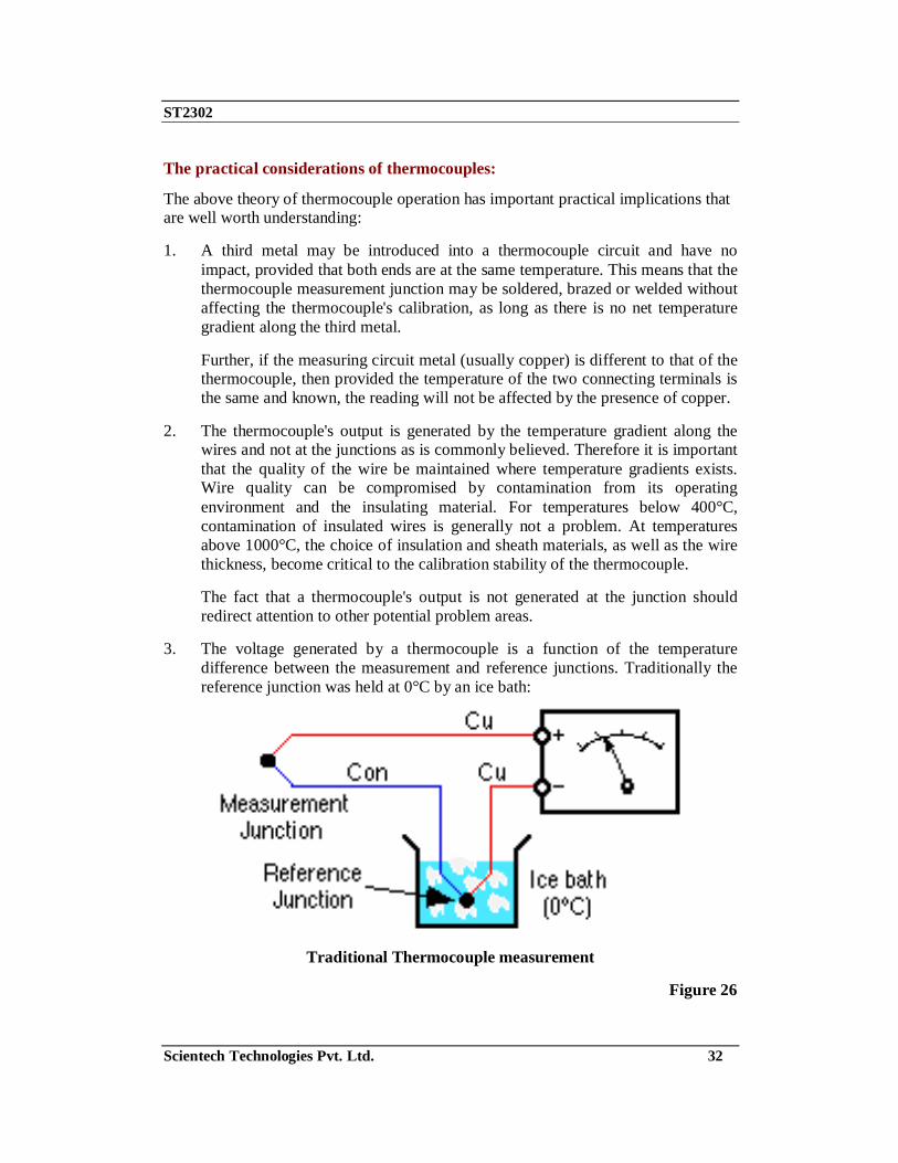
3. The voltage generated by a thermocouple is a function of the temperature difference between the measurement and reference junctions. Traditionally the reference junction was held at 0°C by an ice bath:
Traditional Thermocouple measurement
Figure 26

ST2302
Scientech Technologies Pvt. Ltd. 33
The ice bath is now considered impractical and is replace by a reference junction compensation arrangement. This can be accomplished by measuring the reference junction temperature with an alternate temperature sensor (typically an RTD or thermistor) and applying a correcting voltage to the measured thermocouple voltage before scaling to temperature.
Modern Thermocouple Measurement
Figure 27
The correction can be done electrically in hardware or mathematically in software. The software method is preferred as it is universal to all thermocouple types (provided the characteristics are known) and it allows for the correction of the small non-linearity over the reference temperature range.
4. The low-level output from thermocouples (typically 50mV full scale) requires that care be taken to avoid electrical interference from motors, power cable, transformers and radio signal pickup. Twisting the thermocouple wire pair (say 1 twist per 10 cm) can greatly reduce magnetic field pickup. Using shielded cable or running wires in metal conduit can reduce electric field pickup. The measuring device should provide signal filtering, either in hardware or by software, with strong rejection of the line frequency (50/60 Hz) and its harmonics.
5. The operating environment of the thermocouple needs to be considered. Exposure to oxidizing or reducing atmospheres at high temperature can significantly degrade some thermocouples. Thermocouples containing rhodium (B, R and S types) are not suitable under neutron radiation.

ST2302
Scientech Technologies Pvt. Ltd. 34
The advantages and disadvantages of thermocouples:
Because of their physical characteristics, thermocouples are the preferred method of temperature measurement in many applications. They can be very rugged, are immune to shock and vibration, are useful over a wide temperature range, are simple to manufactured, require no excitation power, there is no self heating and they can be made very small. No other temperature sensor provides this degree of versatility.
Thermocouples are wonderful sensors to experiment with because of their robustness, wide temperature range and unique properties.
On the down side, the thermocouple produces a relative low output signal that is non-linear. These characteristics require a sensitive and stable measuring device that is able provide reference junction compensation and linearization. Also the low signal level demands that a higher level of care be taken when installing to minimise potential noise sources.
The measuring hardware requires good noise rejection capability. Ground loops can be a problem with non-isolated systems, unless the common mode range and rejection is adequate.
Types of Thermocouple:
Thermocouple Sensor Colour Codes Extension and Compensating Leads
Code Type Conductors (+/-) Sensitivity British
BS 1843:1952
E Nickel Chromium / Constantan -200 to 900oC
J Iron / Constantan 0 to 750oC
K Nickel Chromium / Nickel Aluminium -200 to 1250oC
N Nicrosil / Nisil 0 to 1250oC
T Copper / Constantan -200 to 350oC
U Copper / Copper Nickel
Compensating for "S" and "R"
0 to 1450oC
Figure 28

ST2302
Scientech Technologies Pvt. Ltd. 35
The output voltage from a thermocouple is very small, a few milli volts (mV) for a 10oC change in temperature difference and because of this small voltage output some form of amplification is generally needed. The type of amplifier, either discrete or in the form of an Operational Amplifier needs to be carefully selected, because good drift stability is required to prevent recalibration of the thermocouple at frequent intervals. This makes the "Chopper type" of amplifier preferable for most temperature sensing applications.
Temperature V/S Voltage characteristics
Figure 29 Magnitude of thermal EMF
2 21 2 1 2( ) ( )E c T T k T T= − + −
Where c and k = constants of the thermocouple materials T1 = the temperature of the ‘hot’ junction T2 = the temperature of the ‘cold’ or ‘reference’ junction
K Type Thermocouple The operation of a thermocouple is based on the See beck effect which states that if a circuit is formed out of two dissimilar metallic conductors, a current flow in the circuit if one of the junctions is at a higher temperature than the other. There are a number of pairs of metals which exhibit this phenomenon. These metals were arranged in a series by see beck so that in a circuit made up of any two metals, the direction of the current at the hot junction is from the one mentioned earlier in the series to one mentioned later. The metals were arranged as :
Bi - Ni - Co - Pd - U - Cu - Mn - Ti - Hg - Pb - Sn - Cr - Mo - Rh - Ir - Au - Zn - W - Cd - Fe - As - Sb - Te.

ST2302
Scientech Technologies Pvt. Ltd. 36
The thermocouples are designated as J, K, R, S, T types among others depending upon the materials used in making the thermocouple its operational temperature range and so on. The emf of many thermocouples follows the quadratic relationship. It should also be borne in mind that thermocouples are active transducers unlike RTD and thermistors which are passive transducers. Some advantages of thermocouples are that they are cheaper than the resistance thermistors also they are suitable for recording comparatively rapid changes in temperature. They are very convenient for measuring the temperature at one particular point in a piece of apparatus. Some disadvantages are that they have lower accuracy; they have to be protected from environmental contamination, to ensure their long life in their operating environment. Two thermocouples provided on ST2302 module have fairly linear output over temperature range of 0-100°C & magnitude of 41 uV / °C. One is being mounted within the heated enclosure, this being the active unit which will have its 'hot' & 'cold' junctions at different temperatures in operation.
The other unit is mounted outside the heated enclosure and is incorporated in heat sink with an LM335 IC temperature sensor so that the temperature of the cold junction of active thermocouple can be measured. The second thermocouple is connected in series with the first with the wires of the same material connected together. This ensures that the connections to the output circuit are made from the same material which eliminates the possibility of an EMF being introduced into the circuit by connections between different materials. The second thermocouple does not contribute to the output voltage because its 'hot' & 'cold' junctions are maintained at the same temperature. The thermocouple is shown below in Figure 30.
Figure 30
Due to low output of thermocouple amplification is required. An amplifier gain of 200 will give readings within one range of the digital multi-meter. During operation, temperature of ‘cold’ junction varies, due mainly to heat induction from heater along PCB and the junction is in effect 'floating'. This is common occurrence with thermocouple installation where thermocouple leads are short.

ST2302
Scientech Technologies Pvt. Ltd. 37
An LM 335 unit is mounted external to heated enclosure and fitted in a heat sink with second type 'k' thermocouple unit its output being available from the REF socket on that panel. The output from this can be used as an indication of the ambient temperature outside the heated enclosure and that from INT socket indicates the temperature within the heated enclosure. The output from REF socket does not give and accurate value of the room temperature when the heater is in use, due mainly to heat passing along the PCB by conduction from the heater. An LM 335 remotely mounted or some other method is necessary if accurate measurement of ambient temperature is required.
Parameter Minimum Type Maximum
Thermocouple T.C 40.28µV/°C
Reference voltage (LM 335) at T=25°C 2.98V
LM335 T.C 10mV/°C
The Thermocouples are already connected as under :
Figure 31
Recommended testing instruments for experimentation
Digital Multimeter 3½ digit

ST2302
Scientech Technologies Pvt. Ltd. 38
Experiment 1 Objective: Characteristics of IC Temperature Sensor (LM 335) Equipments Required: 1. ST2302with power supply cord
2. Multi Meter 3. Connecting cords
Connection diagram:
Figure 1.1
ST2302
Scientech Technologies Pvt. Ltd. 39
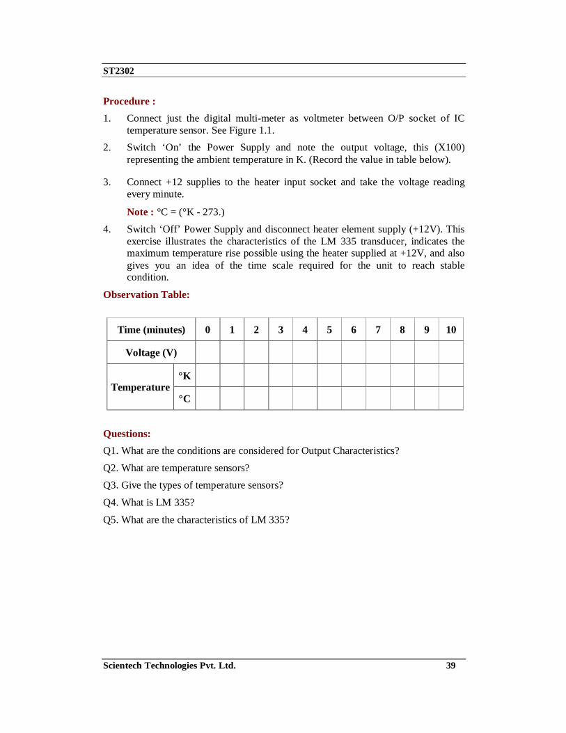
Procedure : 1. Connect just the digital multi-meter as voltmeter between O/P socket of IC
temperature sensor. See Figure 1.1. 2. Switch ‘On’ the Power Supply and note the output voltage, this (X100)
representing the ambient temperature in K. (Record the value in table below).
3. Connect +12 supplies to the heater input socket and take the voltage reading every minute.
Note : °C = (°K - 273.) 4. Switch ‘Off’ Power Supply and disconnect heater element supply (+12V). This
exercise illustrates the characteristics of the LM 335 transducer, indicates the maximum temperature rise possible using the heater supplied at +12V, and also gives you an idea of the time scale required for the unit to reach stable condition.
Observation Table:
Time (minutes) 0 1 2 3 4 5 6 7 8 9 10
Voltage (V)
°K Temperature
°C
Questions: Q1. What are the conditions are considered for Output Characteristics?
Q2. What are temperature sensors? Q3. Give the types of temperature sensors?
Q4. What is LM 335?
Q5. What are the characteristics of LM 335?

ST2302
Scientech Technologies Pvt. Ltd. 40
Experiment 2 Objective : Characteristics of Platinum RTD Equipments Required: 1. ST2302with power supply cord
2. Multi Meter
3. Connecting cords
Connection diagram:
Figure 2.1
Note : Connect/disconnect dotted link as instructed in description.
Parameter Minimum Type Maximum Resistance 99.9 Ohm 100 Ohm 100.1 Ohm
Temperature coefficient +.385 Ohm/°C

ST2302
Scientech Technologies Pvt. Ltd. 41
The Platinum RTD transducer is already connected as under :
Figure 2.2
Procedure: 1. Connect the circuit as shown in Figure 2.1.
a. The Socket 'C' of Slide Potentiometer to +5V. b. The Socket B of Slide Potentiometer to output of Platinum RTD.
c. Connect digital multi-meter as voltmeter on 200 mV or 2V DC range in between output of Platinum RTD & ground.
2. Set the 10K slider resistance midway. 3. Switch ‘on’ the instrument, check the output of IC temperature sensor for
ambient temperature by temporarily connecting DMM on 20V DC range (refer to chart given at the end of experiment 1) and find out the resistance in ohms for this particular temperature.
4. Say for example ambient is 25°C then platinum RTD reading as per chart (see in the end of Experiment. 2) is 109.73.
5. Switch ‘On’ Power Supply adjust the slider control of the 10K Ohm resistance to the voltage drop across the platinum RTD is 109 mV (0.109V) as indicated by digital multi-meter. This calibrates the platinum RTD for an ambient temperature of 25°C since the resistance at 25°C will be 109 ohms. Note that the voltage reading across the RTD in mV is the same as the RTD resistance in ohms, since current flowing must be 0.109/109 = 1 mA
6. Connect the +12V supply to Heater Element input and note the values of the voltage across the RTD with the voltmeter to its 200mV or 2V range, (this representing the RTD resistance) and the output voltage from the IC temperature sensor with the voltmeter set to its 20V range (this representing the temperature of the RTD) after each minute given in below table.
7. Switch ‘Off’ the Power Supply and disconnect Heater element supply (+12)
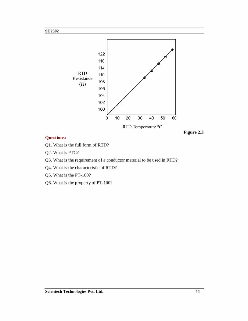
8. Convert RTD temperature into °C & add in above table. 9. Plot the graph of RTD resistance in ohms against temperature in °C. It should
resemble the one given below. Figure 2.3.

ST2302
Scientech Technologies Pvt. Ltd. 42
Observation Table:
Time (minutes) 0 1 2 3 4 5 6 7 8 9 10
°K RTD Temperature °C
RTD Resistance Ohm

ST2302
Scientech Technologies Pvt. Ltd. 43
Temperature Vs Resistance Table :
°C Resistance in ohms °C Resistance in ohms 0 100.00 31 112.06 1 100.39 32 112.44 2 100.78 33 112.83
3 101.17 34 113.22
4 101.56 35 113.61
5 101.95 36 114.99
6 102.34 37 114.38 7 102.73 38 114.77 8 103.12 39 115.15 9 103.51 40 115.54
10 103.90 41 115.93
11 104.29 42 116.31
12 104.68 43 116.70 13 105.07 44 117.08 14 105.46 45 117.47 15 105.85 46 117.86 16 106.23 47 118.24
17 106.62 48 118.63
18 107.01 49 119.01
19 107.40 50 119.40 20 107.79 51 119.78 21 108.18 52 120.17 22 108.57 53 120.55 23 108.95 54 120.94 24 109.34 55 121.32
25 109.73 56 121.70
26 110.12 57 122.09
27 110.51 58 122.47 28 110.89 59 122.86 29 111.28 60 123.24 30 111.67
ST2302
Scientech Technologies Pvt. Ltd. 44
Figure 2.3
Questions: Q1. What is the full form of RTD?
Q2. What is PTC? Q3. What is the requirement of a conductor material to be used in RTD?
Q4. What is the characteristic of RTD? Q5. What is the PT-100?
Q6. What is the property of PT-100?
ST2302
Scientech Technologies Pvt. Ltd. 45
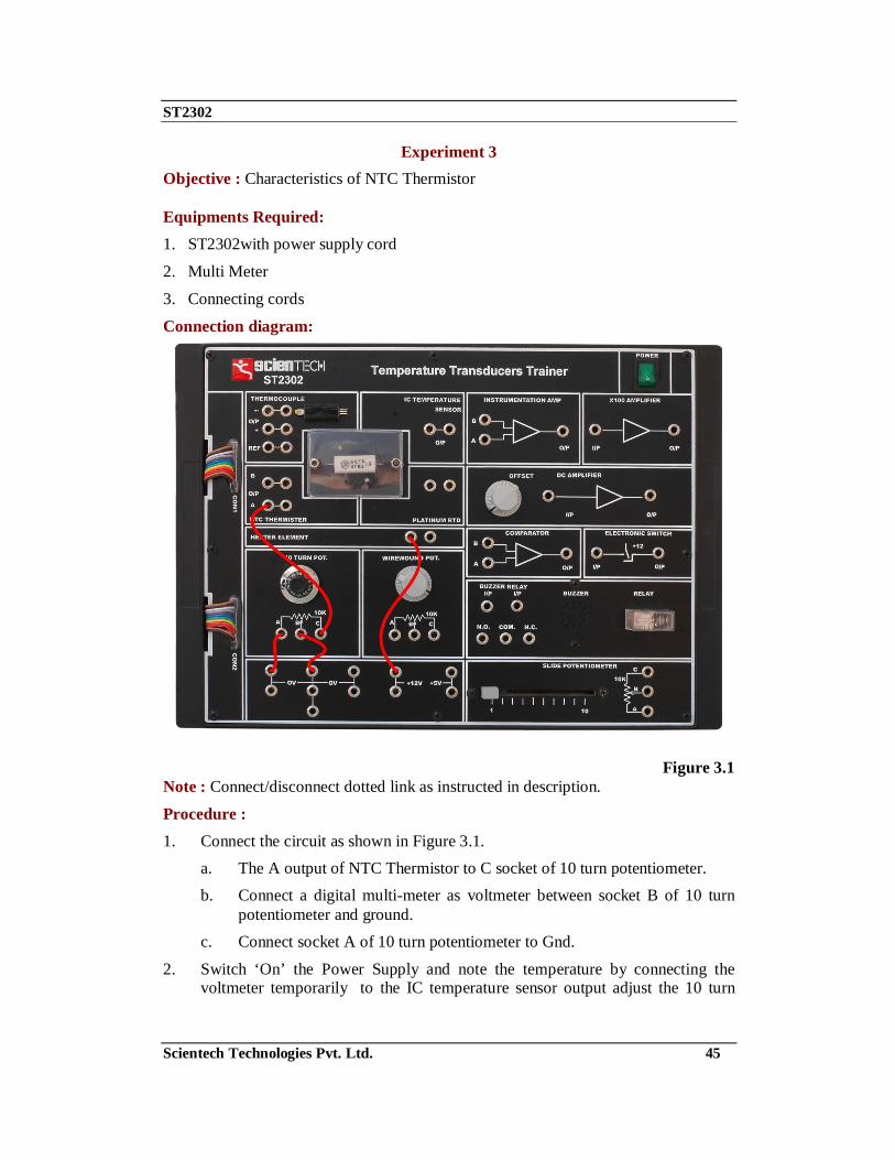
Experiment 3 Objective : Characteristics of NTC Thermistor Equipments Required: 1. ST2302with power supply cord
2. Multi Meter
3. Connecting cords
Connection diagram:
Figure 3.1 Note : Connect/disconnect dotted link as instructed in description. Procedure : 1. Connect the circuit as shown in Figure 3.1.
a. The A output of NTC Thermistor to C socket of 10 turn potentiometer. b. Connect a digital multi-meter as voltmeter between socket B of 10 turn
potentiometer and ground. c. Connect socket A of 10 turn potentiometer to Gnd.
2. Switch ‘On’ the Power Supply and note the temperature by connecting the voltmeter temporarily to the IC temperature sensor output adjust the 10 turn

ST2302
Scientech Technologies Pvt. Ltd. 46
potentiometer until the voltage indicated by voltmeter is 2.5V and then note the dial reading.
Note : Since there is a 1K resistance in the output lead of the Potentiometer the total resistance will be 10 x Dial reading +1K ohms.
3. Connect the +12V supply to the heater element input socket and at 1 minute intervals note the values the dial reading to produce 2.5V across the resistance and also the temperature from the IC temperature sensor. Record the values in above Table.
4. Record the values of dial reading & temperature in below Table. 5. Switch ‘Off’ the Power Supply and disconnect the Heater element supply
(+12V). 6. Plot the graph of thermistor against temperature. It should resemble the graph
below in figure 3.2.
Observation Table:
Time (minutes) 0 1 2 3 4 5 6 7 8 9 10 °K Temperature (from
IC Temperature sensor) °C
Dial reading for 2.5 V Thermistor resistance (10 × dial reading + 1K Ohm)
Figure 3.2

ST2302
Scientech Technologies Pvt. Ltd. 47
Questions: Q1. What is NTC?
Q2. What is Thermistor? Q3. Name the material used for making Thermistor?
Q4. What are the applications of Thermistor?
Q5. How the analogue resistance can be converted into electrical voltage?
Q6. Thermistor are…………………………(active/passive transducer).

ST2302
Scientech Technologies Pvt. Ltd. 48
Experiment 4 Objective : Characteristics of NTC Bridge circuit Equipments Required: 1. ST2302with power supply cord
2. Multi Meter
3. Connecting cords
Connection diagram:
Figure 4.1 Note : Connect/disconnect dotted link as instructed in description.

ST2302
Scientech Technologies Pvt. Ltd. 49
Procedure : 1. Connect the circuit as shown in the Figure 4.1.
2. Socket C of slide potentiometer & wire wound potentiometer to +5V. 3. Socket A of wire wound potentiometer to 0V.
4. Connect a digital voltmeter between socket B of wire wound potentiometer and ground.
5. Connect socket B of slide potentiometer to B Thermistor output. 6. Connect a thermistor output to A of 10 turn potentiometer.
7. Connect B of 10 turn potentiometer to 0V. 8. Switch ‘On’ the Power Supply and adjust the wire wound Potentiometer so that
the voltmeter reading is 2.5V. The fixed branch of the bridge is now set for center balance.
9. Remove DMM and connect it between Thermistor B output and 0V and adjust 2.5 V with slide potentiometer.
10. Now Bridge A and B both are balanced to read 0V difference. Bridge A is point J and K and Bridge B is point L and K. Swing the arm of volt meter between these two bridges and the bridge output for thermistor A and B will be recorded as below table.
11. Now connect +12V supply to the heater input. Note the temperature by measuring the voltage output from the O/P. Socket of the IC temperature sensor & record the value in above Table.
12. Note the temperature & voltages from each bridge circuit at a interval of 1 minute. The bridge 1 output is from NTC output A and socket B of wire wound potentiometer. The bridge 2 output is from Thermistor A O/P and Thermistor B output.
13. Record the values in Table 4.
14. Switch ‘Off’ the Power Supply and disconnect the Heater element supply (+12V).
15. Draw graphs of output voltage against temperature for two bridge circuits on the same axes. They should resemble the Figure 4.2.

ST2302
Scientech Technologies Pvt. Ltd. 50
Observation Table:
Time (minutes) 0 1 2 3 4 5 6 7 8 9 10
°K Temperature (IC Temperature sensor) °C
1 active NTC Bridge
output (V) 2 active
NTC
Figure 4.2
Questions Q1. Give examples of primary and secondary transducers?
Q2. Give examples of active and passive transducers? Q3. To convert resistance to electrical signals which bridge is used?
Q4. What is bridge circuit?
Q5. What are the Characteristics of Transducer?
Q6. What is NTC bridge circuit?

ST2302
Scientech Technologies Pvt. Ltd. 51
Experiment 5 Objective : Characteristics of K Type Thermocouple Equipments Required: 1. ST2302with power supply cord 2. Multi Meter
3. Connecting cords
Connection diagram:
Figure 5.1
Note : Connect/Disconnect dotted link as instructed in description.

ST2302
Scientech Technologies Pvt. Ltd. 52
Procedure : 1. Connect the circuit as shown in Figure 5.1.
a. The '+' output of thermocouple to 'B' input of instrumentation amplifier. b. The '-' output of thermocouple to 'A' input of instrumentation amplifier.
c. Output of instrumentation amplifier to input of X100 amplifier.
d. Output of X100 amplifier to input of DC Amplifier.
e. Connect a digital multi-meter as a voltmeter on 200mV DC range between output of DC amplifier and ground.
2. Switch ‘On’ the Power Supply and then set the Offset control of amplifier as follows :
a. Short circuit the input connections to the instrumentation amplifier and adjust the Offset control for zero indication on voltmeter.
b. Reconnect the thermocouple output to the instrumentation amplifier. The output voltage should still be zero with the 'hot' & 'cold' junction at the same temperature.
3. Find the temperatures of the inside and outside of the enclosure Cold Junction) by using the digital multi-meter on the 20V DC range to measure the output voltage from the O/P socket of the IC temperature sensor and then from the REF output socket of the LM 335 provided on the type 'K' thermocouple.
4. Record the values in below Table.
5. Connect the +12V supply to the heater and at 1 minute intervals, note the values of the thermocouple output voltage (mV), and the voltages representing the temperature of the 'hot' and 'cold' junctions of the thermocouple.
6. Record the values in Table 5.
7. Switch ‘Off’ the Power Supply and disconnect the heater element supply (+12V).
8. Construct the graph of thermocouple output voltage against temperature difference between the 'hot' and 'cold' junctions. Your graph should resemble the one given in Figure 5.2.

ST2302
Scientech Technologies Pvt. Ltd. 53
Thermocouple Reference Chart
°C EMF in µV °C EMF in µV
0 0 26 1041
1 39 27 1081
2 79 28 1122
3 119 29 1162
4 158 30 1203
5 198 31 1244
6 238 32 1285
7 277 33 1325
8 317 34 1366
9 357 35 1407
10 397 36 1448
11 437 37 1489
12 477 38 1529
13 517 39 1570
14 557 40 1611
15 597 41 1652
16 637 42 1693
17 677 43 1734
18 718 44 1776
19 758 45 1817
20 798 46 1858
21 838 47 1899
22 879 48 1940
23 919 49 1981
24 960 50 2022
25 1000

ST2302
Scientech Technologies Pvt. Ltd. 54
Observation Table
Time (minutes) 0 1 2 3 4 5 6 7 8 9 10
Hot junc. INT
Cold junc. REF
Temp.
°K Difference
Thermocouple output (mV)
Observation:
Figure 5.2
Questions: Q1. What is Thermocouple?
Q2. What are the advantages of thermocouple? Q3. Give the types of thermocouple?
Q4. What is thermo electric effect? Q5. Why two dissimilar metal are used to make a thermocouple?

ST2302
Scientech Technologies Pvt. Ltd. 55
Experiment 6 Objective: Temperature Controlled Alarm System (using 1 NTC) Equipments Required: 1. ST2302with power supply cord 2. Multi Meter
3. Connecting cords
Connection diagram:
Figure 6.1
Note : Connect/disconnect dotted link as instructed in description.

ST2302
Scientech Technologies Pvt. Ltd. 56
Procedure : 1. Make the connections as shown in Figure 6.1.
a. Connect A output of NTC to A socket of 10 turn potentiometer. b. Connect B socket of 10 turn potentiometer to 0V.
c. Connect the other end of A output of NTC to A input of Comparator. d. Connect B input of Comparator to B socket of slide potentiometer.
e. Connect A socket of slide potentiometer to 0V. f. Connect C socket of slide potentiometer to +5V.
g. Connect output of Comparator to input of Electronic switch. h. Connect output of Electronic switch to relay input.
i. Connect NO socket of Relay to Buzzer input. j. Connect COM socket of Relay to 0V.
2. Adjust 2.5V at A output of NTC with the help of 10 turn potentiometer. 3. Adjust 3.3V at B input of Comparator of with the help of slide potentiometer.
4. Connect Digital multi-meter at 20V DC range between IC Temperature sensor output and 0V to get the temperature inside the enclosure.
5. Connect +12V supply to input of heater element, and note temperature inside the enclosure and record it in the Table given below.
6. Note the temperature and time in minutes at which the buzzer starts ringing. This is the temperature when the voltage at the A input of Comparator increases the voltage at its B input by the virtue of NTC characteristics.
Observation Table:
Time (minutes) 0 1 2 3 4 5 6 7 8 9 10
°K IC Temperature
sensor output °C

ST2302
Scientech Technologies Pvt. Ltd. 57
Experiment 7 Objective: Temperature Controlled Alarm System (using 2 NTC) Equipments Required: 1. ST2302with power supply cord
2. Multi Meter
3. Connecting cords
Connection diagram:
Figure 7.1
Note : Connect/disconnect dotted link as instructed in description.
ST2302
Scientech Technologies Pvt. Ltd. 58
Procedure: 1. Make the connections as shown in Figure 7.1
a. Connect A output of NTC thermistor to a socket of 10 turn potentiometer. b. Connect B socket of 10 turn potentiometer to 0V
c. Connect B socket of NTC thermistor to B socket of wire wound potentiometer.
d. Connect A socket of wire wound potentiometer to 0V. e. Connect C socket of wire wound potentiometer to +5V.
f. Connect A output of NTC to A input of instrumentation amplifier. g. Connect B output of NTC to B input of instrumentation amplifier.
h. Connect output of instrumentation amplifier to A input of comparator. i. Connect B input of comparator to B socket of slide potentiometer
j. Connect C socket of slide potentiometer to +5V. k. Connect A socket of slide potentiometer to 0V.
l. Connect output of comparator to input of Electronic switch. m. Connect output of Electronic switch to relay input.
n. Connect NO socket of Relay to Buzzer input. o. Connect COM socket of Relay to 0V.
2. Adjust 2.5 V at A NTC output with 10 turn potentiometer. 3. Adjust 2.5 V at B NTC output with wire wound potentiometer.
4. Check the output of instrumentation amplifier is nearly 0V. 5. Adjust slide potentiometer socket B at 0.8V.
6. Connect +12 supply to heater input, and note the temperature within the enclosure at 1 minute intervals by connecting the multi-meter between output of IC Temperature sensor and 0V. Record the results in the Table given below.
7. Note the temperature and time in minutes when the buzzer rings. This is the temperature when the voltage at both the inputs of comparator is equal. You will observe that in previous experiment with 1 NTC we have set comparators input at 2.5V and 3.3V, giving a difference of 0.8V. Whereas, in this experiment we have kept the same voltage difference of 0.8V at the comparator input and used 2 Thermistors. You have observed that the buzzer started ringing in 3-4 minutes to reach the difference of 0.8V which shows that 2 NTC bridge network is giving more output and is more sensitive.

ST2302
Scientech Technologies Pvt. Ltd. 59
Observation Table:
Time (minutes) 0 1 2 3 4 5 6 7 8 9 10
IC Temperature K
sensor output °C
Questions: Q1. List major elements of Electronic Instrumentation system? Q2. What is the difference between sensor and transducer?
Q3. What do you understand by primary and secondary transducers? Q4. What do you understand by active and passive transducers?
Q5. What do you understand by analog and digital transducers? Q6. What do you understand by transducer and inverse transducers?

ST2302
Scientech Technologies Pvt. Ltd. 60
Frequently asked questions Q1. List major elements of Electronic Instrumentation system?
Ans: Electronic Instrumentation system generally consists of three major elements:
1. Input Device ( Transducers or sensors ) 2. Signal Conditioning or Processing Circuitry
3. Output Device (Display)
Q2. What is the difference between sensor and transducer? Ans: The sensor senses the condition, state or value of the process variable and produces an output which reflects this condition, state or value.
The transducer transforms the energy of the process variable to an output of some other energy which is able to operate some control device.
Q3. What do you understand by primary and secondary transducers? Ans: A primary transducer is one which responds to physical phenomenon or a change in physical phenomenon. The response of primary transducer must be closely related to the physical phenomenon. A secondary transducer is one which transforms the output of the primary transducer to an electrical output.
Q4. What do you understand by active and passive transducers? Ans: Passive transducers derive the power required for transduction from an auxiliary power source. They also derive part of the power required for conversion from the physical quantity. Active transducers are those which do not require an auxiliary power source to produce their output. Since, they develop their own voltage or current output. The energy required for production of output signal is obtained from physical quantity being measured.
Q5. What do you understand by analog and digital transducers? Ans: Analog transducers convert input quantity into an analog output which is a continuous function of time. Digital transducers convert the input quantity into an electrical output which is in the form of pulses.
Q6. What do you understand by transducer and inverse transducers? Ans: Transducers can be broadly defined as a device which converts a non electrical quantity into an electrical quantity.
An inverse transducer is a device which converts an electrical quantity into a non electrical quantity.
Q7. Give examples of primary and secondary transducers? Ans: Primary Transducers: LDR, Photo diode, RTD
Secondary Transducer: Wheat Stone Bridge, LVDT

ST2302
Scientech Technologies Pvt. Ltd. 61
Q8. Give examples of active and passive transducers? Ans: Active transducer: Solar cell, Piezo Electric crystal, Thermocouple Passive transducer: LDR, Photo diode, RTD
Q9. Give examples of analog and digital transducers? Ans: Analog transducer: LDR, Photo diode, RTD Digital Transducer :Techometer
Q10. Give examples of transducer and inverse transducers? Ans: Transducer: Microphone
Inverse Transducer: Loud speaker
Q11. What are the Characteristics of Transducer? Ans: When choosing a transducer for any application, the input, transfer & output characteristics have to be taken into account.
Q12. What are the conditions are considered for Output Characteristics? Ans: The three conditions in the output characteristics which should be considered:
a. Type of electrical output,
b. Output Impedance, c. Useful Range.
Q13. What are temperature sensors? Ans: Temperature Sensors measure the amount of heat energy or even coldness within an object or system, and can "sense" or detect any physical change to that temperature.
Q14. Give the types of temperature sensors? Ans: Temperature sensors consist of two basic physical types:
• Contact Types - These types of temperature sensors are required to be in physical contact with the object being sensed and uses conduction to monitor changes in temperature. They can be used to detect solids, liquids or gases over a wide range of temperatures.
• Non-contact Types - These types of temperature sensors detect the Radiant Energy being transmitted from the object in the form of Infra-red radiation. They can be used with any solid or liquid that emits radiant energy.
This is an IC containing 16 transistors 9 resistance and 2 capacitors contained in a transistor type package. It provides an output of 10mV/° K, measurements of output voltage therefore indicate the temperature directly in degrees Kelvin e.g. at a temperature of 20°C (293 °K) the output voltage will be 2.93V.

ST2302
Scientech Technologies Pvt. Ltd. 62
Q15. What is LM 335? Ans: It is a temperature sensor having16 transistors 9 resistance and 2 capacitors contained in a transistor type package.
Q16. What are the characteristics of LM 335?
Ans: It provides an output of 10mV/° K, measurements of output voltage therefore indicate the temperature directly in degrees Kelvin e.g. at a temperature of 20°C (293 °K) the output voltage will be 2.93V.
Q17. What is the full form of RTD? Ans: Resistance Temperature Detector.
Q18. What is PTC? Ans: Positive temperature coefficient of resistance.
Q19. What is the requirement of a conductor material to be used in RTD? Ans: The requirements of a conductor material to be used in RTD’s are:
1. The change in resistance of material per unit change in temperature should be as large as possible.
2. The material should have high value of resistance so that minimum volume of material is used for the construction of RTD.
3. The resistance of material should have continuous and stable relationship with temperature.
Q20. What is the characteristic of RTD? Ans: When Temperature increases it metal resistance also increases.
Q21. What is the PT-100? Ans: Platinum 100,it shows 100 ohms output at 0°C.
Q22. What is the property of PT-100? Ans: For 100Ω platinum RTD, a change of only 0.4 Ω would be expected if the temperature is changed by 1°C
Q23. What is NTC? Ans: Negative temperature coefficient of resistance.
Q24. What is Thermistor? Ans: Thermistor is a contraction of a term thermal resistor. Thermistor has a negative temperature coefficient i.e. their resistance decreases with increase in temperature.

ST2302
Scientech Technologies Pvt. Ltd. 63
Q25. Name the material used for making Thermistor? Ans: Thermistor is composed of a sintered mixture of metallic oxides, such as Mn, Ni, Co, Cu, Fe, & U. Their resistance range from 0.5 Ω to 75MΩ and they are available in wide variety of shapes and sizes.
Q26. What are the applications of Thermistor? Ans: Applications of Thermistor include:
1. Measurement of power at high frequencies. 2. Measurement of Thermal Conductivity.
3. Measurement of level, flow and pressure of liquids. 4. Measurement of composition of gases.
5. Vacuum measurements.
Q27. What is NTC bridge circuit? Ans: It is made up of two Thermistors would normally be used there being connected in a bridge circuit
Q28. What is Thermocouple? Ans: It basically consists of two junctions of dissimilar metals, such as copper and constantan that are welded or crimped together. One junction is kept at a constant temperature called the reference (Cold) junction, while the other the measuring (Hot) junction is used as the temperature sensor
Q29. What are the advantages of thermocouple? Ans: The Thermocouple is the most commonly used type of all the temperature sensing devices due to its simplicity, ease of use and their speed of response to changes in temperature, due mainly to their small size. Thermocouples also have the widest temperature range of all the temperature sensing devices from below -200oC to well over 2000oC.
Q30. Give the types of thermocouple? Ans: The thermocouples are designated as J, K, R, S, T types among others depending upon the materials used in making the thermocouple its operational temperature range
ST2302
Scientech Technologies Pvt. Ltd. 64
Glossary of Terms (Transducers)
Transducer : A device which converts information from one energy system to another.
Sensor : A device which senses, or measures, the magnitude of system variables. Normally they also convert the measured quantity into another energy system and hence they are also transducers.
Actuator : A device which accepts an input in one system and converts it into another energy system which is normally mechanical. These devices are also transducers.
Accuracy : The error present in a measurement as compared to the true value of the quantity.
Sensitivity : The ratio of the output of a device compared to the magnitude of input quantity.
Range : A statement of the values over which the device can be used and within which the accuracy is within the stated specification.
Bandwidth : The range of input signal frequencies over which a device or circuit is being operated while providing an output within its stated specification.
Transfer function : The mathematical relationship between two variables. Normally the relationship between the input and output of a system.
Linear Ratio : A relationship between two quantities that have a constant for example, a graphical straight line relationship.
Non linear : A relationship between two quantities that cannot be described by a linear relationship.
Linearity : A measure of the deviation of a measurement from an ideal straight line response to the same measurement over the same range.
Response time : The time taken for the output to reach, or be within a rated percentage of, a new final value, after the input has been changed.

ST2302
Scientech Technologies Pvt. Ltd. 65
Warranty 1 We guarantee the product against all manufacturing defects for 24 months from
the date of sale by us or through our dealers. Consumables like dry cell etc. are not covered under warranty.
2 The guarantee will become void, if
a) The product is not operated as per the instruction given in the operating manual.
b) The agreed payment terms and other conditions of sale are not followed.
c) The customer resells the instrument to another party. d) Any attempt is made to service and modify the instrument.
3 The non-working of the product is to be communicated to us immediately giving full details of the complaints and defects noticed specifically mentioning the type, serial number of the product and date of purchase etc.
4 The repair work will be carried out, provided the product is dispatched securely packed and insured. The transportation charges shall be borne by the customer. For any Technical Problem Please Contact us at [email protected]
List of Accessories 1. Patch Cord 16"........................................................................................15 Nos.
2. Mains Cord .............................................................................................1 No. 3. e-Manual ................................................................................................1 No.
Updated 31-03-2010