Temperature dependence of macrobending loss in all-fiber bend loss edge filter
5
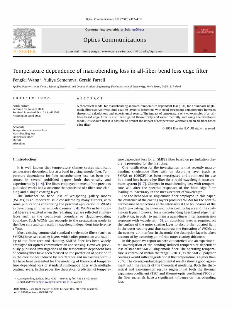
Temperature dependence of macrobending loss in all-fiber bend loss edge filter Pengfei Wang * , Yuliya Semenova, Gerald Farrell Applied Optoelectronics Center, School of Electronic and Communications Engineering, Dublin Institute of Technology, Kevin Street, Dublin 8, Ireland article info Article history: Received 16 January 2008 Received in revised form 21 April 2008 Accepted 21 April 2008 Keywords: Temperature dependent loss Macrobending loss Singlemode fiber SMF28 Edge filter abstract A theoretical model for macrobending-induced temperature dependent loss (TDL) for a standard single- mode fiber (SMF28) with dual coating layers is presented, with good agreement demonstrated between theoretical calculations and experimental results. The impact of temperature on two examples of an all- fiber based edge filter is also investigated theoretically and experimentally and using the developed model, it is shown that it is possible to predict the impact of temperature variations on an all-fiber based edge filter. Ó 2008 Elsevier B.V. All rights reserved. 1. Introduction It is well known that temperature change causes significant temperature dependent loss at a bend in a singlemode fiber. Tem- perature dependence for fiber macrobending loss has been pre- sented in several published papers both theoretically and experimentally [1–4]. The fibers employed in most of the previous published works had a structure that consisted of a fiber core, clad- ding and a single coating layer. The influence on bend loss of whispering gallery modes (WGMs) is an important issue considered by many authors, with some publications considering the practical application of WGMs in developing an interferometric sensor [3,4]. WGMs in bent opti- cal fibers are excited when the radiating rays are reflected at inter- faces such as the coating–air boundary or cladding–coating boundary. Such WGMs can recouple to the propagating mode in the fiber core and can result in wavelength dependent interference effects. Most existing commercial standard singlemode fibers (such as SMF28) have two coating layers, which offer protection and stabil- ity to the fiber core and cladding. SMF28 fiber has been widely employed for optical communication and sensing. However, previ- ously published investigations of the temperature dependent loss of bending fiber have been focused on the prediction of phase shift in the core modes induced by interference and no existing formu- las have been presented for the modeling of theoretical tempera- ture dependent loss of standard singlemode fiber with multiple coating layers. In this paper, the theoretical prediction of tempera- ture dependent loss for an SMF28 fiber based on perturbation the- ory is presented for the first time. One justification for the investigation is that recently macro- bending singlemode fiber with an absorbing layer (such as SMF28 or 1060XP) has been investigated and optimized for use in a bend loss based edge filter for a rapid wavelength measure- ment system [5–7]. Changes in macrobending loss with tempera- ture will alter the spectral responses of the fiber edge filter leading to inaccuracy in the measurement of wavelength. For the bent SMF28 singlemode fiber employed in this paper, the existence of the coating layers produces WGMs for the bent fi- ber because of reflections at the interfaces at the boundaries of the cladding–coating, the inner and outer coating layers and the coat- ing–air layers. However, for a macrobending fiber based edge filter application, in order to maintain a quasi-linear filter transmission response with wavelength [5], an absorbing layer is required on the surface of the outer coating layer to absorb the radiated light in the outer coating and thus suppress the formation of WGMs at the coating–air interface. In the model the absorption layer is taken account of by assuming an infinite outer coating thickness. In this paper, we report on both a theoretical and an experimen- tal investigation of the bending induced temperature dependent loss of standard SMF28 singlemode fiber. The operating tempera- ture is controlled within the range 0–70 °C, as the SMF28 polymer coatings would suffer degradation if the temperature is higher than 70 °C. The corresponding experimental results show a good agree- ment with the results of the theoretical modeling. Both the theo- retical and experimental results suggest that both the thermal expansion coefficient (TEC) and thermo-optic coefficient (TOC) of the fiber materials have a significant influence on macrobending loss. 0030-4018/$ - see front matter Ó 2008 Elsevier B.V. All rights reserved. doi:10.1016/j.optcom.2008.04.050 * Corresponding author. Tel.: +353 1 4024812; fax: +353 1 4024690. E-mail address: [email protected] (P. Wang). Optics Communications 281 (2008) 4312–4316 Contents lists available at ScienceDirect Optics Communications journal homepage: www.elsevier.com/locate/optcom
-
Upload
pengfei-wang -
Category
Documents
-
view
212 -
download
0
Transcript of Temperature dependence of macrobending loss in all-fiber bend loss edge filter
Optics Communications 281 (2008) 4312–4316
Contents lists available at ScienceDirect
Optics Communications
journal homepage: www.elsevier .com/locate/optcom
Temperature dependence of macrobending loss in all-fiber bend loss edge filter
Pengfei Wang *, Yuliya Semenova, Gerald FarrellApplied Optoelectronics Center, School of Electronic and Communications Engineering, Dublin Institute of Technology, Kevin Street, Dublin 8, Ireland
a r t i c l e i n f o
Article history:Received 16 January 2008Received in revised form 21 April 2008Accepted 21 April 2008
Keywords:Temperature dependent lossMacrobending lossSinglemode fiberSMF28Edge filter
0030-4018/$ - see front matter � 2008 Elsevier B.V. Adoi:10.1016/j.optcom.2008.04.050
* Corresponding author. Tel.: +353 1 4024812; fax:E-mail address: [email protected] (P. W
a b s t r a c t
A theoretical model for macrobending-induced temperature dependent loss (TDL) for a standard single-mode fiber (SMF28) with dual coating layers is presented, with good agreement demonstrated betweentheoretical calculations and experimental results. The impact of temperature on two examples of an all-fiber based edge filter is also investigated theoretically and experimentally and using the developedmodel, it is shown that it is possible to predict the impact of temperature variations on an all-fiber basededge filter.
� 2008 Elsevier B.V. All rights reserved.
1. Introduction
It is well known that temperature change causes significanttemperature dependent loss at a bend in a singlemode fiber. Tem-perature dependence for fiber macrobending loss has been pre-sented in several published papers both theoretically andexperimentally [1–4]. The fibers employed in most of the previouspublished works had a structure that consisted of a fiber core, clad-ding and a single coating layer.
The influence on bend loss of whispering gallery modes(WGMs) is an important issue considered by many authors, withsome publications considering the practical application of WGMsin developing an interferometric sensor [3,4]. WGMs in bent opti-cal fibers are excited when the radiating rays are reflected at inter-faces such as the coating–air boundary or cladding–coatingboundary. Such WGMs can recouple to the propagating mode inthe fiber core and can result in wavelength dependent interferenceeffects.
Most existing commercial standard singlemode fibers (such asSMF28) have two coating layers, which offer protection and stabil-ity to the fiber core and cladding. SMF28 fiber has been widelyemployed for optical communication and sensing. However, previ-ously published investigations of the temperature dependent lossof bending fiber have been focused on the prediction of phase shiftin the core modes induced by interference and no existing formu-las have been presented for the modeling of theoretical tempera-ture dependent loss of standard singlemode fiber with multiplecoating layers. In this paper, the theoretical prediction of tempera-
ll rights reserved.
+353 1 4024690.ang).
ture dependent loss for an SMF28 fiber based on perturbation the-ory is presented for the first time.
One justification for the investigation is that recently macro-bending singlemode fiber with an absorbing layer (such asSMF28 or 1060XP) has been investigated and optimized for usein a bend loss based edge filter for a rapid wavelength measure-ment system [5–7]. Changes in macrobending loss with tempera-ture will alter the spectral responses of the fiber edge filterleading to inaccuracy in the measurement of wavelength.
For the bent SMF28 singlemode fiber employed in this paper,the existence of the coating layers produces WGMs for the bent fi-ber because of reflections at the interfaces at the boundaries of thecladding–coating, the inner and outer coating layers and the coat-ing–air layers. However, for a macrobending fiber based edge filterapplication, in order to maintain a quasi-linear filter transmissionresponse with wavelength [5], an absorbing layer is required onthe surface of the outer coating layer to absorb the radiated lightin the outer coating and thus suppress the formation of WGMs atthe coating–air interface. In the model the absorption layer is takenaccount of by assuming an infinite outer coating thickness.
In this paper, we report on both a theoretical and an experimen-tal investigation of the bending induced temperature dependentloss of standard SMF28 singlemode fiber. The operating tempera-ture is controlled within the range 0–70 �C, as the SMF28 polymercoatings would suffer degradation if the temperature is higher than70 �C. The corresponding experimental results show a good agree-ment with the results of the theoretical modeling. Both the theo-retical and experimental results suggest that both the thermalexpansion coefficient (TEC) and thermo-optic coefficient (TOC) ofthe fiber materials have a significant influence on macrobendingloss.
P. Wang et al. / Optics Communications 281 (2008) 4312–4316 4313
2. Modeling for temperature dependent loss of singlemode fiberwith dual coating layers
As is well known, the refractive index of an optical material de-pends on temperature and wavelength. For silica material, therefractive index varies with the temperature as a result of latticedeformations in the silica matrix structure. For a fiber polymercoating material, the variation of the refractive index is inducedby the amplitude of vibrations of polymer molecules and resultsin the translation and distortion of the cross-linked network withinthe polymer long molecule structure.
A series of theoretical formulations have been developed [8–12]for the prediction of the macrobending loss of singlemode fibers.For example, the theoretical modeling of fiber bending loss basedon weak perturbance of the guide field for a multi-coating struc-ture (such as SMF28) has been presented in Ref. [12], along withcomparisons with the modeling of fiber macrobending loss whichwere presented in previous publications [8–11]. Based on the sat-isfactory agreement between the calculated and experimental re-sults for SMF28 fiber in Ref. [12], the model presented in Ref.[12] is employed in this paper to predict the temperature depen-dent loss of bending SMF28 singlemode fiber.
Fig. 1 gives the schematic cross-section of a bending fiber withmultiple cladding or coating layers. The bending radius is denotedby R. For the q-th (q is a positive integer, q = 1,2,3 . . .) layer of fiber,its refractive index is nq and the thickness is xq�xq�1. q = 1 repre-sents the core and q = 2 represents the cladding layer.
As a starting point, the analysis in Ref. [10] is used, In Ref. [10],the fiber was assumed to consist of a core, cladding (q = 2) and aninfinite coating (q = 3). When the fiber is bent, the Fourier trans-form scalar field in the cladding and infinite coating regions(q = 2,3) in the y-direction can be expressed as
r2t�wqðx; fÞ þ k2n2
q 1þ 2xR
� �� b2
0 � f2� �
�wqðx; fÞ ¼ 0 ð1Þ
where �wqðx; fÞ is the Fourier transform along the y-direction of thetransverse field component in region q; f is the conjugate variablefor the Fourier transform in y-direction; nq is the refractive indexin region q; k is the well know wavenumber in vacuum at the wave-length k, it can be expressed as k ¼ 2p=2; ð1þ 2x
R Þ is the correctionfactor for n2
q to take account of the change induced by the stress-op-tic effect; and b0 is the complex propagation constant, the imagi-nary part of which is the bend loss coefficient. Following solutionby an inverse Fourier transform of the y-field, Eq. (1) can be treatedas [11]
wqðx; yÞ ¼1
2p
Z þ1
�1DqðfÞBiðXqÞ þ HqðfÞAiðXqÞ� �
� expð�ifyÞdf ð2Þ
Core: n1
n2 n3 nq
x1 x2 xq-1
R nq-1
xq-20
y
Fig. 1. Cross-section of a bending fiber with multiple coating layers.
where Xðx; fÞ ¼ R2k2n2
q
� �2=3
b2 þ f2 � k2n2qð1þ 2x
R Þh i
; and Bi and Ai are
Airy functions, respectively. Both DqðfÞ and HqðfÞ are the Fourierspectra which were previously defined in Ref. [10]. For the outer-most infinite layer, the relation between DqðfÞ and HqðfÞ can be de-fined as HqðfÞ ¼ �iDqðfÞ. Thus by extending the model, for any twoadjacent layers in the fiber structure, given the continuous bound-ary conditions of the field, the adjacent fields are given by [12]
DqðfÞBi½Xqðxq; fÞ� þ HqAi½Xqðxq; fÞ�¼ Dqþ1ðfÞBi½Xqðxqþ1; fÞ� þ Hqþ1Ai½Xqðxqþ1; fÞ�
DqðfÞB0i½Xqðxq; fÞ� þ HqA0i½Xqðxq; fÞ�¼ Dqþ1ðfÞB0i½Xqðxqþ1; fÞ� þ Hqþ1A0i½Xqðxqþ1; fÞ�
8>>><>>>:
ð3Þ
which has the form ofDjðfÞHjðfÞ
� �¼ M11 M12
M21 M22
� �Djþ1ðfÞHjþ1ðfÞ
� �. Consider-
ing the core and cladding layer, the relationship between D1ðfÞand H1ðfÞ is obtained as the following
D1ðfÞ ¼M11iþM12
M21iþM22H1ðfÞ ¼ GH1ðfÞ ð4Þ
Given the boundary condition at the interface between the corelayer and cladding layer, then
D1ðfÞBi½X2ðx1; fÞ� þ H1ðfÞAi½X2ðx1; fÞ�
¼ pffiffiffiffiffiffiffiffiffiffiffiffiffiffiffic2 þ f2
q exp �affiffiffiffiffiffiffiffiffiffiffiffiffiffiffic2 þ f2
q� �ð5Þ
Therefore, H1ðfÞ ¼pffiffiffiffiffiffiffiffi
c2þf2p exp �a
ffiffiffiffiffiffiffiffiffic2þf2p
GBi ½X1ðx1 ;fÞ�þAi ½X1ðx1 ;fÞ�and finally according to pertur-
bation theory the bend loss factor can be expressed as
2a ¼ �2j2
2pbV2K21ðacÞ
ImZ 1
�1H1ðfÞAi½X2ð0; fÞ�df
� �ð6Þ
This factor can be used for the calculation of bend loss for a fiberwith one or more coating layers, and the above formulas are usedin the investigation which follows of the temperature dependenceof bending loss for SMF28 fiber.
In most previously published papers [9–11], the effective bendradius (a wavelength dependent correction factor) was employedto take account of stress induced refractive index changes in orderto achieve a good agreement between the modeled results and theexperimental results. However, in our previously published work[12], the good agreement between the theoretical model andexperimental results for Corning standard singlemode fiber-SMF28 showed that for this particular fiber, the so-called ‘‘effectivebending radius” used to take account of macrobending stress, wasnot required. SMF28 is the fiber type employed in the investiga-tions of temperature dependent loss in this paper. For the theoret-ical model employed in this paper, to maintain generality, thestress-optic effect is included in the model and all formulas, butin applying the model for SMF28 fiber, the value of the correctionfactor is set equal to 1.
For the fiber used in this paper the key parameters at 20 �C areshown in Table 1.
While most of the parameter values are published by the man-ufacturer of SMF28, some TEC and TOC values were extracted fromRef. [13].
With the parameters of TEC and TOC listed in Table 1, the cor-responding temperature dependent thickness and refractive indexof each fiber layer at a temperature T can be expressed as
xT ¼ ðxq � xq�1Þ � aq � DT ð7ÞnT ¼ nq � bq � DT ð8Þ
where xq is the distance from the fiber core center to the q-th fiberlayer boundary as shown in Fig. 1; aq is the TEC of the q-th layer of
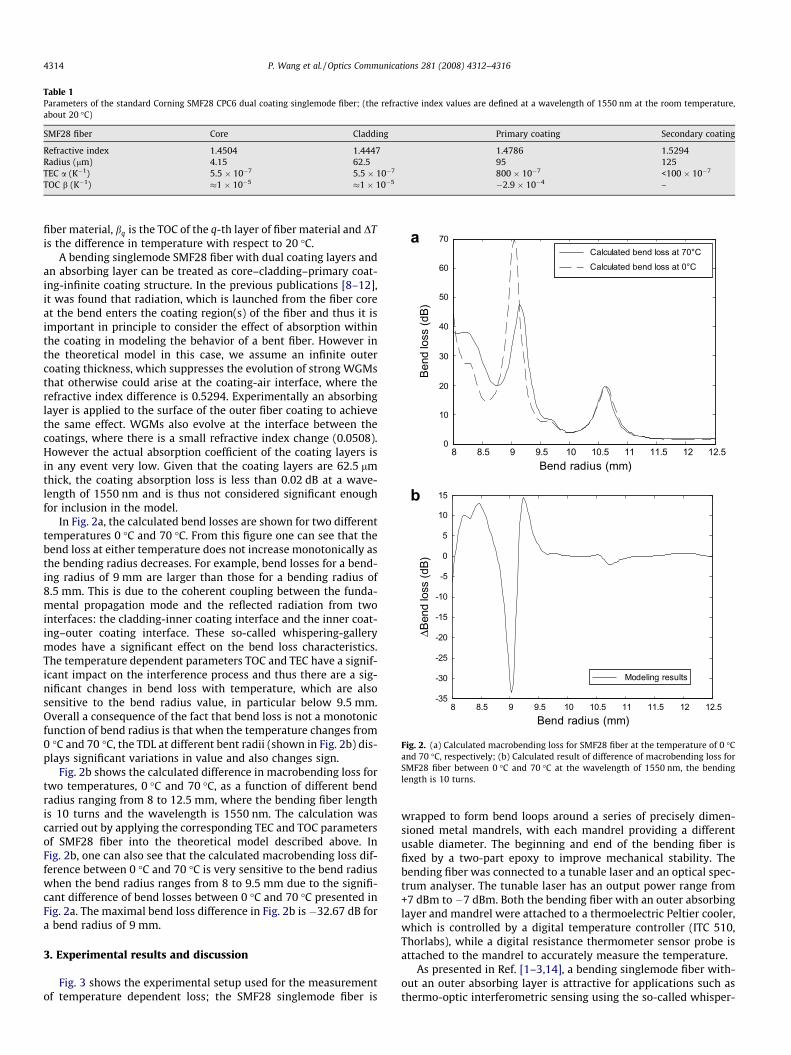
Table 1Parameters of the standard Corning SMF28 CPC6 dual coating singlemode fiber; (the refractive index values are defined at a wavelength of 1550 nm at the room temperature,about 20 �C)
SMF28 fiber Core Cladding Primary coating Secondary coating
Refractive index 1.4504 1.4447 1.4786 1.5294Radius (lm) 4.15 62.5 95 125TEC a (K�1) 5.5 � 10�7 5.5 � 10�7 800 � 10�7 <100 � 10�7
TOC b (K�1) �1 � 10�5 �1 � 10�5 �2.9 � 10�4 –
8 8.5 9 9.5 10 10.5 11 11.5 12 12.50
10
20
30
40
50
60
70
Bend radius (mm)
Bend
loss
(dB)
Calculated bend loss at 70°CCalculated bend loss at 0°C
8 8.5 9 9.5 10 10.5 11 11.5 12 12.5-35
-30
-25
-20
-15
-10
-5
0
5
10
15
Bend radius (mm)
ΔBen
d lo
ss (d
B)
Modeling results
a
b
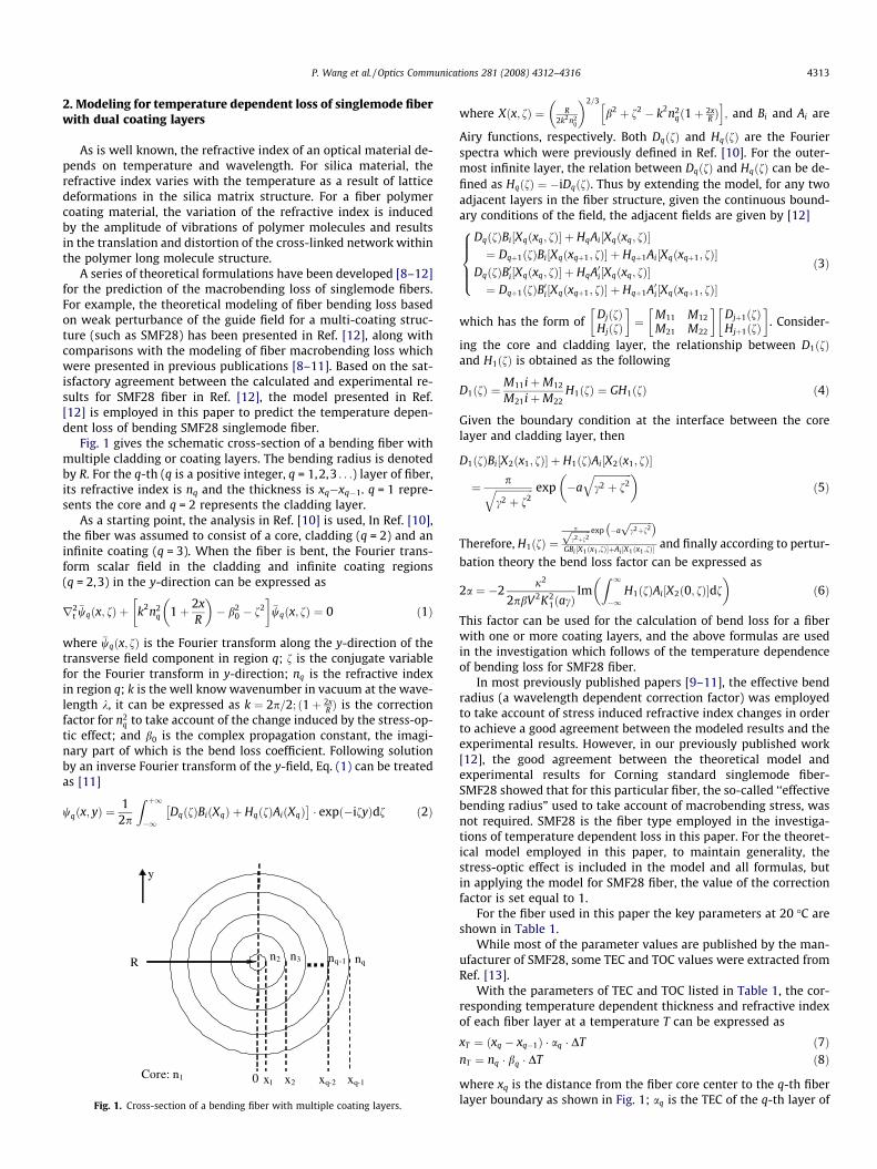
Fig. 2. (a) Calculated macrobending loss for SMF28 fiber at the temperature of 0 �Cand 70 �C, respectively; (b) Calculated result of difference of macrobending loss forSMF28 fiber between 0 �C and 70 �C at the wavelength of 1550 nm, the bendinglength is 10 turns.
4314 P. Wang et al. / Optics Communications 281 (2008) 4312–4316
fiber material, bq is the TOC of the q-th layer of fiber material and DTis the difference in temperature with respect to 20 �C.
A bending singlemode SMF28 fiber with dual coating layers andan absorbing layer can be treated as core–cladding–primary coat-ing-infinite coating structure. In the previous publications [8–12],it was found that radiation, which is launched from the fiber coreat the bend enters the coating region(s) of the fiber and thus it isimportant in principle to consider the effect of absorption withinthe coating in modeling the behavior of a bent fiber. However inthe theoretical model in this case, we assume an infinite outercoating thickness, which suppresses the evolution of strong WGMsthat otherwise could arise at the coating-air interface, where therefractive index difference is 0.5294. Experimentally an absorbinglayer is applied to the surface of the outer fiber coating to achievethe same effect. WGMs also evolve at the interface between thecoatings, where there is a small refractive index change (0.0508).However the actual absorption coefficient of the coating layers isin any event very low. Given that the coating layers are 62.5 lmthick, the coating absorption loss is less than 0.02 dB at a wave-length of 1550 nm and is thus not considered significant enoughfor inclusion in the model.
In Fig. 2a, the calculated bend losses are shown for two differenttemperatures 0 �C and 70 �C. From this figure one can see that thebend loss at either temperature does not increase monotonically asthe bending radius decreases. For example, bend losses for a bend-ing radius of 9 mm are larger than those for a bending radius of8.5 mm. This is due to the coherent coupling between the funda-mental propagation mode and the reflected radiation from twointerfaces: the cladding-inner coating interface and the inner coat-ing–outer coating interface. These so-called whispering-gallerymodes have a significant effect on the bend loss characteristics.The temperature dependent parameters TOC and TEC have a signif-icant impact on the interference process and thus there are a sig-nificant changes in bend loss with temperature, which are alsosensitive to the bend radius value, in particular below 9.5 mm.Overall a consequence of the fact that bend loss is not a monotonicfunction of bend radius is that when the temperature changes from0 �C and 70 �C, the TDL at different bent radii (shown in Fig. 2b) dis-plays significant variations in value and also changes sign.
Fig. 2b shows the calculated difference in macrobending loss fortwo temperatures, 0 �C and 70 �C, as a function of different bendradius ranging from 8 to 12.5 mm, where the bending fiber lengthis 10 turns and the wavelength is 1550 nm. The calculation wascarried out by applying the corresponding TEC and TOC parametersof SMF28 fiber into the theoretical model described above. InFig. 2b, one can also see that the calculated macrobending loss dif-ference between 0 �C and 70 �C is very sensitive to the bend radiuswhen the bend radius ranges from 8 to 9.5 mm due to the signifi-cant difference of bend losses between 0 �C and 70 �C presented inFig. 2a. The maximal bend loss difference in Fig. 2b is �32.67 dB fora bend radius of 9 mm.
3. Experimental results and discussion
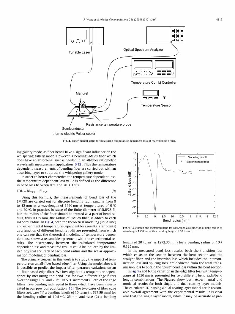
Fig. 3 shows the experimental setup used for the measurementof temperature dependent loss; the SMF28 singlemode fiber is
wrapped to form bend loops around a series of precisely dimen-sioned metal mandrels, with each mandrel providing a differentusable diameter. The beginning and end of the bending fiber isfixed by a two-part epoxy to improve mechanical stability. Thebending fiber was connected to a tunable laser and an optical spec-trum analyser. The tunable laser has an output power range from+7 dBm to �7 dBm. Both the bending fiber with an outer absorbinglayer and mandrel were attached to a thermoelectric Peltier cooler,which is controlled by a digital temperature controller (ITC 510,Thorlabs), while a digital resistance thermometer sensor probe isattached to the mandrel to accurately measure the temperature.
As presented in Ref. [1–3,14], a bending singlemode fiber with-out an outer absorbing layer is attractive for applications such asthermo-optic interferometric sensing using the so-called whisper-
Semiconductorthermo-electric Peltier cooler
Optical Spectrum Analyzer Tunable Laser
Temperature Combi Controller
Temperature Sensor
Mandrel
Resistance temperature probe
Fig. 3. Experimental setup for measuring temperature dependent loss of macrobending fiber.
8 8.5 9 9.5 10 10.5 11 11.5 12 12.5-35
-30
-25
-20
-15
-10
-5
0
5
10
15
Bend radius (mm)
Modeling resultExperimental data
Δ Be
nd lo
ss (d
B)
Fig. 4. Calculated and measured bend loss of SMF28 as a function of bend radius atwavelength 1550 nm with a bending length of 10 turns.
P. Wang et al. / Optics Communications 281 (2008) 4312–4316 4315
ing gallery mode, as fiber bends have a significant influence on thewhispering gallery mode. However, a bending SMF28 fiber whichdoes have an absorbing layer is needed in an all-fiber ratiometricwavelength measurement application [6,12]. Thus the temperaturedependent measurements of bending fiber are carried out with anabsorbing layer to suppress the whispering gallery mode.
In order to better characterize the temperature dependent loss,the temperature dependent loss value is defined as the differencein bend loss between 0 �C and 70 �C thus
TDL ¼ BL70�
C � BL0�
C ð9Þ
Using this formula, the measurements of bend loss of theSMF28 are carried out for discrete bending radii ranging from 8to 12 mm at a wavelength of 1550 nm at temperatures of 0 �Cand 70 �C. In practice, because of the finite diameter of SMF28 fi-ber, the radius of the fiber should be treated as a part of bend ra-dius, thus 0.125 mm, the radius of SMF28 fiber, is added to eachmandrel radius. In Fig. 4, both the theoretical modeling (solid line)and experimental temperature dependent loss results (star points)as a function of different bending radii are presented, from whichone can see that the theoretical modeling of temperature depen-dent loss shows a reasonable agreement with the experimental re-sults. The discrepancy between the calculated temperaturedependent loss and measured results could be induced by the lim-ited physical accuracy of each bend radius and the scalar approxi-mation modeling of bending loss.
The primary concern in this work is to study the impact of tem-perature on an all-fiber based edge filter. Using the model above, itis possible to predict the impact of temperature variations on anall-fiber based edge filter. We investigate this temperature depen-dence by measuring the bend loss for two different edge filtersover the range 0 �C and 70 �C, in 5 �C increments. Both of the edgefilters have bending radii equal to those which have been investi-gated in our previous publication [15]. The two cases of fiber edgefilters are, case (1) a bending length of 10 turns (is 667.59 mm) forthe bending radius of 10.5 + 0.125 mm and case (2) a bending
length of 20 turns (is 1272.35 mm) for a bending radius of 10 +0.125 mm.
In the measured bend loss results, both the transition losswhich exists in the section between the bent section and thestraight fiber, and the insertion loss which includes the intercon-nection loss and splicing loss, are deducted from the total trans-mission loss to obtain the ‘‘pure” bend loss within the bent section.
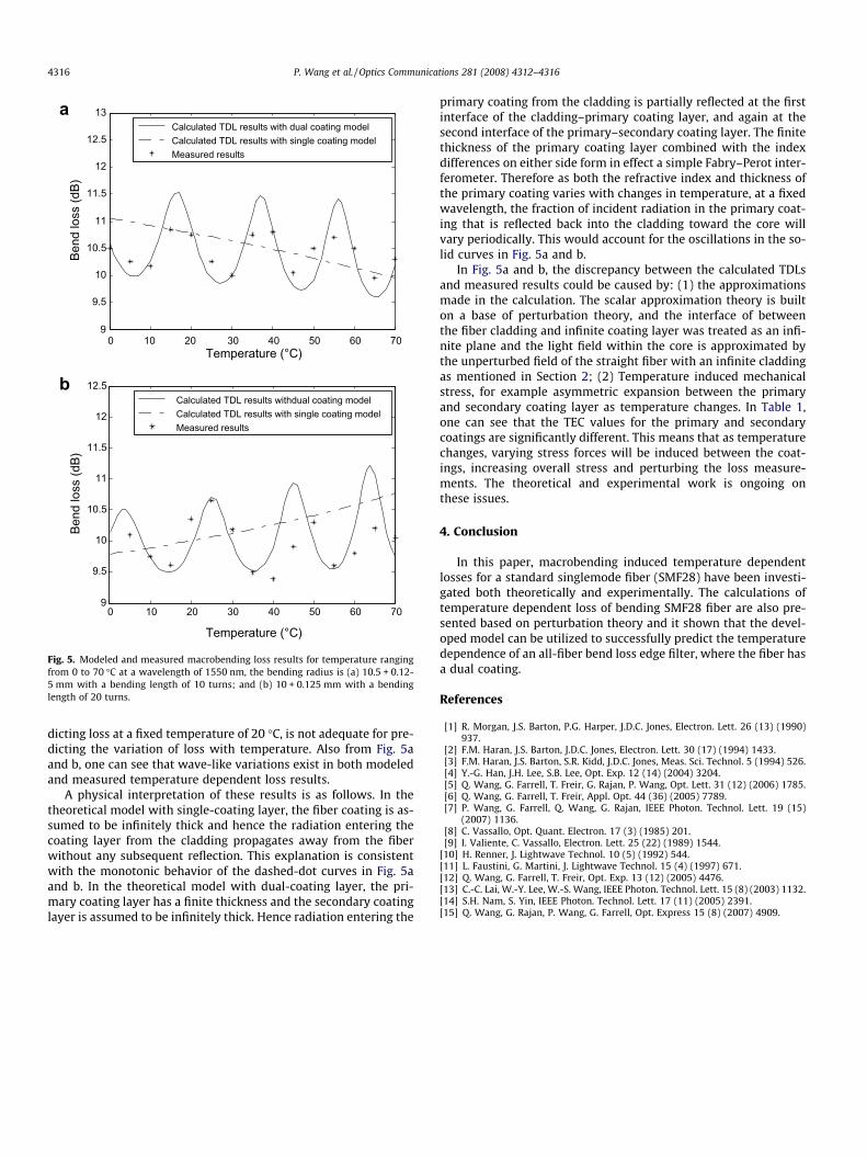
In Fig. 5a and b, the variation in the edge filter loss with temper-ature at 1550 nm is presented for two different bend radii/bendlength combinations. The Figures show both experimental andmodeled results for both single and dual coating layer models.The calculated TDLs using a dual coating layer model are in reason-able overall agreement with the experimental results. It is clearalso that the single layer model, while it may be accurate at pre-
0 10 20 30 40 50 60 709
9.5
10
10.5
11
11.5
12
12.5
13
Temperature (°C)
Temperature (°C)
Bend
loss
(dB)
Calculated TDL results with dual coating modelCalculated TDL results with single coating model Measured results
0 10 20 30 40 50 60 709
9.5
10
10.5
11
11.5
12
12.5
Bend
loss
(dB)
Calculated TDL results withdual coating modelCalculated TDL results with single coating modelMeasured results
a
b
Fig. 5. Modeled and measured macrobending loss results for temperature rangingfrom 0 to 70 �C at a wavelength of 1550 nm, the bending radius is (a) 10.5 + 0.12-5 mm with a bending length of 10 turns; and (b) 10 + 0.125 mm with a bendinglength of 20 turns.
4316 P. Wang et al. / Optics Communications 281 (2008) 4312–4316
dicting loss at a fixed temperature of 20 �C, is not adequate for pre-dicting the variation of loss with temperature. Also from Fig. 5aand b, one can see that wave-like variations exist in both modeledand measured temperature dependent loss results.
A physical interpretation of these results is as follows. In thetheoretical model with single-coating layer, the fiber coating is as-sumed to be infinitely thick and hence the radiation entering thecoating layer from the cladding propagates away from the fiberwithout any subsequent reflection. This explanation is consistentwith the monotonic behavior of the dashed-dot curves in Fig. 5aand b. In the theoretical model with dual-coating layer, the pri-mary coating layer has a finite thickness and the secondary coatinglayer is assumed to be infinitely thick. Hence radiation entering the
primary coating from the cladding is partially reflected at the firstinterface of the cladding–primary coating layer, and again at thesecond interface of the primary–secondary coating layer. The finitethickness of the primary coating layer combined with the indexdifferences on either side form in effect a simple Fabry–Perot inter-ferometer. Therefore as both the refractive index and thickness ofthe primary coating varies with changes in temperature, at a fixedwavelength, the fraction of incident radiation in the primary coat-ing that is reflected back into the cladding toward the core willvary periodically. This would account for the oscillations in the so-lid curves in Fig. 5a and b.
In Fig. 5a and b, the discrepancy between the calculated TDLsand measured results could be caused by: (1) the approximationsmade in the calculation. The scalar approximation theory is builton a base of perturbation theory, and the interface of betweenthe fiber cladding and infinite coating layer was treated as an infi-nite plane and the light field within the core is approximated bythe unperturbed field of the straight fiber with an infinite claddingas mentioned in Section 2; (2) Temperature induced mechanicalstress, for example asymmetric expansion between the primaryand secondary coating layer as temperature changes. In Table 1,one can see that the TEC values for the primary and secondarycoatings are significantly different. This means that as temperaturechanges, varying stress forces will be induced between the coat-ings, increasing overall stress and perturbing the loss measure-ments. The theoretical and experimental work is ongoing onthese issues.
4. Conclusion
In this paper, macrobending induced temperature dependentlosses for a standard singlemode fiber (SMF28) have been investi-gated both theoretically and experimentally. The calculations oftemperature dependent loss of bending SMF28 fiber are also pre-sented based on perturbation theory and it shown that the devel-oped model can be utilized to successfully predict the temperaturedependence of an all-fiber bend loss edge filter, where the fiber hasa dual coating.
References
[1] R. Morgan, J.S. Barton, P.G. Harper, J.D.C. Jones, Electron. Lett. 26 (13) (1990)937.
[2] F.M. Haran, J.S. Barton, J.D.C. Jones, Electron. Lett. 30 (17) (1994) 1433.[3] F.M. Haran, J.S. Barton, S.R. Kidd, J.D.C. Jones, Meas. Sci. Technol. 5 (1994) 526.[4] Y.-G. Han, J.H. Lee, S.B. Lee, Opt. Exp. 12 (14) (2004) 3204.[5] Q. Wang, G. Farrell, T. Freir, G. Rajan, P. Wang, Opt. Lett. 31 (12) (2006) 1785.[6] Q. Wang, G. Farrell, T. Freir, Appl. Opt. 44 (36) (2005) 7789.[7] P. Wang, G. Farrell, Q. Wang, G. Rajan, IEEE Photon. Technol. Lett. 19 (15)
(2007) 1136.[8] C. Vassallo, Opt. Quant. Electron. 17 (3) (1985) 201.[9] I. Valiente, C. Vassallo, Electron. Lett. 25 (22) (1989) 1544.
[10] H. Renner, J. Lightwave Technol. 10 (5) (1992) 544.[11] L. Faustini, G. Martini, J. Lightwave Technol. 15 (4) (1997) 671.[12] Q. Wang, G. Farrell, T. Freir, Opt. Exp. 13 (12) (2005) 4476.[13] C.-C. Lai, W.-Y. Lee, W.-S. Wang, IEEE Photon. Technol. Lett. 15 (8) (2003) 1132.[14] S.H. Nam, S. Yin, IEEE Photon. Technol. Lett. 17 (11) (2005) 2391.[15] Q. Wang, G. Rajan, P. Wang, G. Farrell, Opt. Express 15 (8) (2007) 4909.