Temperature and Void Reactivity njj*f*rt/v MMi9t ...
45
©ml ORNL/TM-12386 OAK RIDGE NATIONAL LABORATORY njj*f*rt/v MMi9t Temperature and Void Reactivity Coefficient Calculations for the High Flux Isotope Reactor Safety Analysis Report W. W. Engle, Jr. L. R. Williams MANAGED BY MARTIN MARIETTA ENERGY SYSTEMS, INC. FOR THE UNITED STATES DEPARTMENT OF ENERGY DISTRIBUTION OF TH.S DOCUMENT 6 UNUMTIH
Transcript of Temperature and Void Reactivity njj*f*rt/v MMi9t ...

©ml ORNL/TM-12386
OAK RIDGE NATIONAL LABORATORY
njj*f*rt/v MMi9t
Temperature and Void Reactivity Coefficient Calculations for the
High Flux Isotope Reactor Safety Analysis Report
W. W. Engle, Jr. L. R. Williams
MANAGED BY MARTIN MARIETTA ENERGY SYSTEMS, INC. FOR THE UNITED STATES DEPARTMENT OF ENERGY
DISTRIBUTION OF TH.S DOCUMENT 6 UNUMTIH
This report has been reproduced directly from the best available copy.
Available to DOE and DOE contractors from the Office of Scientific and Technical Information, P.O. Box 62, Oak Ridge, TN 37831; prices available from (615) 576-8401, FTS 626-8401.
Available to the public from the National Technical Information Service, U.S. Department of Commerce, 5285 Port Royal Rd., Springfield, VA 22161.
This report was prepared as an account of work sponsored by an agency of the United States Government. Neither the United States Government nor any agency thereof, nor any of their employees, makes any warranty, express or implied, or assumes any legal liability or responsibility for the accuracy, completeness, or usefulness of any information, apparatus, product, or process disclosed, or represents that its use would not infringe privately owned rights. Reference herein to any specific commercial product, process, or service by trade name, trademark, manufacturer, or otherwise, does not necessarily constitute or imply its endorsement, recommendation, or favoring by the United States Government or any agency thereof. The views and opinions of authors expressed herein do not necessarily state or reflect those of the United States Government or any agency thereof.
DISCLAIMER
Portions of this document may be illegible in electronic image products. Images are produced from the best available original document.

ORNL/TM-12386
Engineering Physics and Mathematics Division
Temperature and Void Reactivity Coefficient Calculations for the High Flux Isotope Reactor
Safety Analysis Report
W. W. Engle, Jr. L. R. Williams
Date Published—July 1994
NOTICE This document contains information of a preliminary nature. It is subject to revision or correction and therefore does not represent a final report
Prepared by the OAK RIDGE NATIONAL LABORATORY
Oak Ridge, Tennessee 37831 managed by
MARTIN MARIETTA ENERGY SYSTEMS, INC. for the
U.S. DEPARTMENT OF ENERGY under contract DE-AC05-84OR21400
DISTRIBUTION OF THIS DOCUMENT IS UNLlMlTEE
f-

TABLE OF CONTENTS
LIST OF TABLES v
LIST OF FIGURES vii
ACKNOWLEDGEMENTS ix
1. INTRODUCTION 1
2. METHODS VERIFICATION 3 2.1. Cross-Section Processing 3 2.2. Method of Analysis 3 2.3. Results of Calculation 4
3. TEMPERATURE AND VOID COEFFICIENT CALCULATIONS . . . . . . . . 9 3.1. Beginning-of-Life Calculations 9 3.2. Beginning-of-Life Results 11 3.3. End-of-Life and Equilibrium-Xenon Calculations 11 3.4 End-of-Life and Equilibrium-Xenon Results 11
3. CONCLUSIONS 15
4. REFERENCES 17
APPENDIX A 19
i i i


LIST OF TABLES
Table 2.1. Calculated Relative Power Distribution 7
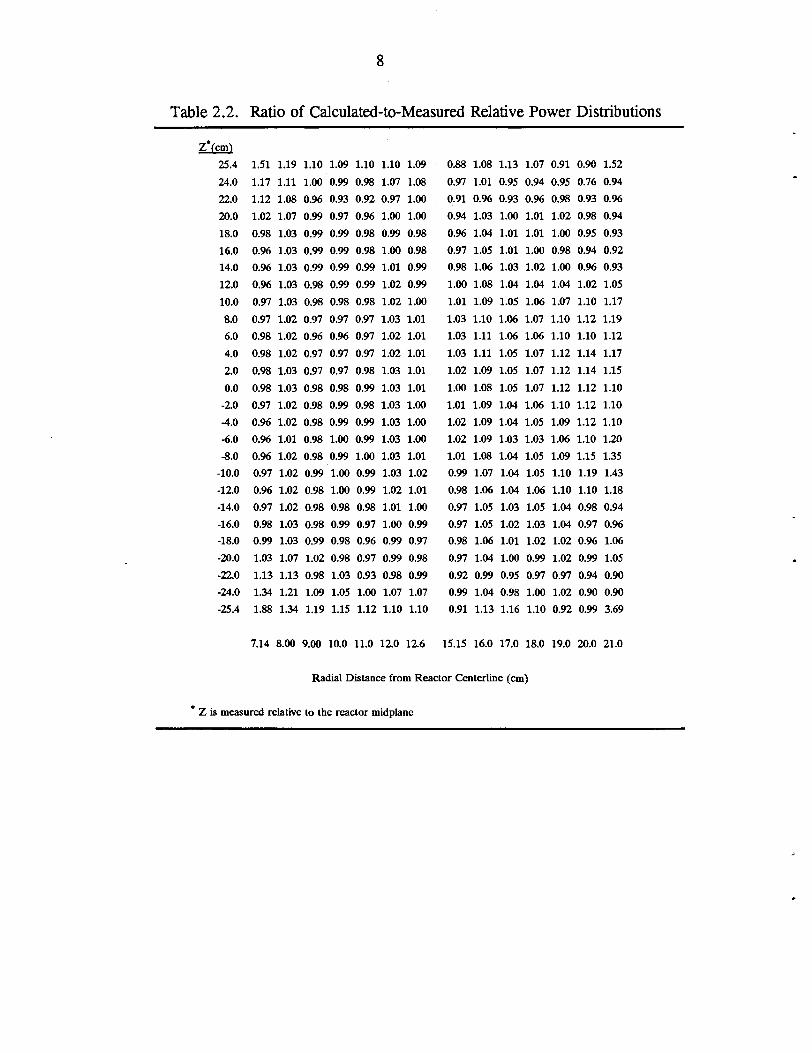
Table 2.2. Ratio of Calculated-to-Measured Relative Power Distributions . . . . 8
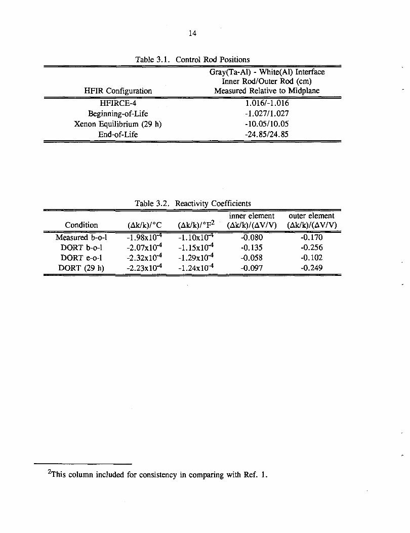
Table 3.1. Control Rod Positions 14
Table 3.2. Reactivity Coefficients 14
v


LIST OF FIGURES
Fig. 2.1. HFIRCE-4 DORT Geometry Model 5
Fig. 2.2. HFIRCE-4 DORT Geometry Model - Central Region 6
Fig. 3.1. HFIR DORT Beginning-of-Life Model - Central Region 10
Fig. 3.2. HFIR DORT End-of-Life Model - Central Region 12
Fig. 3.3. HFIR DORT Equilibrium Xenon Model - Central Region 13
vii


ACKNOWLEDGEMENTS
R. T. Primm, III, provided valuable assistance in the course of these calculations by modifying the format of the neutron cross sections used in previous work so that they could be used in the DORT code, by providing material compositions and control rod positions for the end-of-life and xenon equilibrium conditions and by participating in several useful discussions concerning the calculational techniques and computer models. R. B. Rothrock served as technical and administrative liaison with the Research Reactors Division and also provided valuable input via many constructive discussions of the calculational procedures and the HFIR DORT models.
ix

1
1. INTRODUCTION
This report provides documentation of a series of calculations performed in 1991 in order to provide input for the High Flux Isotope Reactor Safety Analysis Report. In particular, temperature and void reactivity coefficients were calculated for beginning-of-life, end-of-life, and xenon equilibrium (29 h) conditions. Much of the data used to prepare the computer models for these calculations was derived from the original HFIR nuclear design study (Ref. 1).

3
2. METHODS VERIFICATION
In order to verify both the computer code and the cross-section data used in these analyses, a mockup of the HFIR critical experiment, HFIRCE-4, was calculated. The relative power distribution from that calculation was then compared with the relative power distribution reported in Ref. 1.
2.1. Cross-Section Processing
The processing of the cross sections used in the calculations described in the remainder of this report was reported in detail in Ref. 2. To summarize, the ANSL-V General Purpose Neutron library (Ref. 3) was processed using the AJAX, BONAMI, NITAWL, and XSDRNPM modules of the AMPX system (Ref. 4) in order to produce the 39 group cross-section library used in these analyses.
2.2. Method of Analysis
The discrete ordinates code, DORT (Ref. 5) was used to analyze the HFIRCE-4 experiment and determine the k-effective, neutron fluxes and the power distribution. The discrete ordinates method is a numerical technique that yields highly differential results for the entire system being calculated. In the calculation, the system is divided into finite space cells and the calculation maintains a balance between particle gains and losses for each space cell. With the origin (source) of the particles specified and the boundary conditions set, the calculation begins with the highest energy group and sweeps through all lower energy groups and all space cells in the system for all particle directions. Several sweeps (iterations) are required before the results converge to give the number of particles from the source's high-energy group that have entered each space cell, together with their resulting energies and directions. The procedure is repeated for each energy group in decreasing order. In a multiplying system, the fission source is then recalculated using the most recently computed fluxes and the sweep through the energy groups is repeated. This process is repeated until the fission source calculation converges. The results of interest are usually the average particle fluxes in each energy group for each space cell, the fission source in each space cell, and the k-effective value.
The major shortcoming of the DORT discrete ordinates code is that it is limited to two-dimensional geometries. Thus, if a reactor system is to be analyzed by the DORT code, it must be describable in two dimensions. In the case of the HFIR, this is not a significant limitation. DORT also has numerous advantages, not the least of which is its ability to produce large volumes of detailed flux data for essentially all points within a system in a relatively short time and at a relatively economical cost.

4
The DORT calculation used an R-Z model which was derived from data presented in Figs. A.8 through A.10 and Table A.6 of Ref. 1. The model explicitly included 18 radial fuel regions, 9 each in the inner and outer fuel elements, the central target region, the control rods, the beryllium reflector and the surrounding water. The boundaries of the radial fuel regions and the axial spatial mesh in the fuel region were chosen so that the calculated power density could be compared directly with the relative power distribution shown in Fig. 7.8. in Ref. 1. The HFIRCE-4 core and the DORT computer model contain approximately 0.7 x 10"3 kg less boron as a burnable poison than is contained in the HFIR production cores. Figure 2.1 shows a computer generated plot of the HFIR DORT geometry and Figure 2.2 shows an enlarged view of the target,fuel, and control rod region which more clearly depicts the region descriptions in the DORT geometry. A complete listing of the DORT input data is presented in Appendix A.
2.3. Results of Calculation
The calculated relative power distribution is shown in Table 2.1. and the ratio of the calculated relative power distribution to the measured relative power distribution from Fig 7.8. in Ref. 1 is shown in Table 2.2.
Note in Table 2.2. that only 20 out of 378 values of the calculated to measured ratios show more than a twenty percent discrepancy and 335 out of the 378 values agree to within ten percent or better. The worst disagreement is at the axial ends of the inner edge of the inner fuel element and at the axial ends of the outer edge of the outer fuel element. The method of extrapolation/interpolation of the original measurements made with fission foils is not well understood and the agreement between the calculation and the measurement is considered to be a sufficient verification of the DORT code and cross-section library for their use in the reactivity coefficient calculations described in the following sections of this report.

5
HFIRCE-4 R-Z MODEL - BEGINNING OF CYCLE
S2
RADIUS (cm)
Fig. 2.1. HFIRCE-4 DORT Geometry Model

6
HFRCE-4 R-Z MODEL - BEGINNING OF CYCLE
30
25-
2 0 -
1 5 -
1 0 -
5 -
0 -
- 5 -
- 1 0
- 1 5 -
- 2 0 -
- 2 5 -
-30 H 1 ' | ' 'l 0 . 0 7 .5
T — r — i — i " f " i—|— 15.0 22 .5 30 .0
RADIUS (em)
Fig. 2.2. HFIRCE-4 DORT Geometry Model - Central Region

7
Table 2.1. Calculated Relative Power Distribution
Zfcml 25.4 1.286 1.540 1.679 1.750 1.721 1.600 1.464 1.442 1.690 1.621 1.368 1.023 0.641 0.365 24.0 1.039 0.989 0.894 0.879 0.872 0.960 1.026 1.021 0.940 0.758 0.646 0.529 0.393 0.273 22.0 0.987 0.929 0.812 0.785 0.789 0.873 0.927 0.927 0.876 0.713 0.606 0.497 0.372 0.258 20.0 1.039 0.993 0.879 0.854 0.857 0.936 0.979 0.980 0.949 0.788 0.674 0.553 0.410 0.281 18.0 1.127 1.085 0.968 0.944 0.949 1.030 1.074 1.077 1.051 0.880 0.756 0.622 0.463 0.316 16.0 1.224 1.181 1.058 1.035 1.041 1.130 1.178 1.183 1.158 0.974 0.841 0.699 0.527 0.367
14.0 1.318 1.273 1.143 1.120 1.128 1.226 1.278 1.287 1.264 1.071 0.935 0.791 0.612 0.444 12.0 1.404 1.357 1.221 1.198 1.208 1.315 1.371 1.384 1.364 1.166 1.036 0.908 0.755 0.608 10.0 1.479 1.431 1.288 1.265 1.278 1.392 1.452 1.471 1.453 1.253 1.132 1.030 0.916 0.816 8.0 1.541 1.492 1.344 1.322 1.336 1.457 1.520 1.545 1.529 1.328 1.215 1.132 1.043 0.964 6.0 1.590 1.540 1.388 1.366 1.381 1.508 1.573 1.603 1.588 1.383 1.272 1.195 1.115 1.046 4.0 1.623 1.573 1.418 1.396 1.412 1.543 1.610 1.642 1.627 1.418 1.306 1.230 1.149 1.081 2.0 1.640 1.589 1.433 1.411 1.428 1.560 1.629 1.659 1.645 1.433 1.319 1.234 1.139 1.047 0.0 1.642 1.591 1.435 1.413 1.430 1.562 1.631 1.660 1.646 1.433 1.317 1.227 1.119 1.003
-2.0 1.629 1.578 1.423 1.400 1.417 1.547 1.616 1.644 1.630 1.418 1.302 1.212 1.105 0.992 -4.0 1.602 1.551 1.398 1.375 1.391 1.518 1.585 1.610 1.597 1.389 1.275 1.190 1.099 1.003 -6.0 1.558 1.508 1.358 1.335 1.349 1.472 1.536 1.559 1.545 1.342 1.230 1.149 1.059 0.972 -8.0 1.500 1.452 1.306 1.283 1.295 1.411 1.472 1.490 1.475 1.275 1.164 1.078 0.982 0.889
-10.0 1.430 1383 1.243 1.219 1.229 1.336 1.393 1.407 1.386 1.189 1.065 0.960 0.846 0.741 -12.0 1.349 1.303 1.170 1.145 1.153 1.252 1.303 1.313 1.287 1.089 0.953 0.811 0.636 0.458 -14.0 1.259 1.215 1.088 1.064 1.069 1.158 1.204 1.210 1.180 0.985 0.842 0.674 0.473 0.273 -16.0 1.162 1.120 1.001 0.976 0.979 1.059 1.099 1.106 1.070 0.887 0.745 0.590 0.397 0.220 -18.0 1.065 1.023 0.910 0.885 0.886 0.959 0.994 0.999 0.963 0.794 0.663 0.519 0.347 0.191 -20.0 0.977 0.932 0.822 0.796 0.796 0.865 0.902 0.900 0.864 0.707 0.587 0.457 0.306 0.168 -22.0 0.924 0.868 0.756 0.728 0.728 0.802 0.849 0.844 0.792 0.635 0.524 0.407 0.274 0.153 -24.0 0.967 0.918 0.827 0.809 0.800 0.876 0.934 0.921 0.842 0.668 0.553 0.430 0.288 0.162 -25.4 1.186 1.422 1.546 1.605 1.572 1.453 1.336 1.280 1.496 1.406 1.157 0.823 0.473 0.222
7.14 8.00 9.00 10.00 11.00 12.00 12.60 15.15 16.00 17.00 18.00 19.00 20.00 21.00
Radial Distance from Reactor Centerline (cm)
Z is measured relative to the reactor midplane
8
Table 2.2. Ratio of Calculated-to-Measured Relative Power Distributions
Z*fcm1 25.4 1.51 1.19 1.10 1.09 1.10 1.10 1.09 0.88 1.08 1.13 1.07 0.91 0.90 1.52 24.0 1.17 1.11 1.00 0.99 0.98 1.07 1.08 0.97 1.01 0.95 0.94 0.95 0.76 0.94 22.0 1.12 1.08 0.96 0.93 0.92 0.97 1.00 0.91 0.96 0.93 0.96 0.98 0.93 0.96 20.0 1.02 1.07 0.99 0.97 0.96 1.00 1.00 0.94 1.03 1.00 1.01 1.02 0.98 0.94 18.0 0.98 1.03 0.99 0.99 0.98 0.99 0.98 0.96 1.04 1.01 1.01 1.00 0.95 0.93 16.0 0.96 1.03 0.99 0.99 0.98 1.00 0.98 0.97 1.05 1.01 1.00 0.98 0.94 0.92 14.0 0.96 1.03 0.99 0.99 0.99 1.01 0.99 0.98 1.06 1.03 1.02 1.00 0.96 0.93 12.0 0.96 1.03 0.98 0.99 0.99 1.02 0.99 1.00 1.08 1.04 1.04 1.04 1.02 1.05 10.0 0.97 1.03 0.98 0.98 0.98 1.02 1.00 1.01 1.09 1.05 1.06 1.07 1.10 1.17 8.0 0.97 1.02 0.97 0.97 0.97 1.03 1.01 1.03 1.10 1.06 1.07 1.10 1.12 1.19 6.0 0.98 1.02 0.96 0.96 0.97 1.02 1.01 1.03 1.11 1.06 1.06 1.10 1.10 1.12 4.0 0.98 1.02 0.97 0.97 0.97 1.02 1.01 1.03 1.11 1.05 1.07 1.12 1.14 1.17 2.0 0.98 1.03 0.97 0.97 0.98 1.03 1.01 1.02 1.09 1.05 1.07 1.12 1.14 1.15 0.0 0.98 1.03 0.98 0.98 0.99 1.03 1.01 1.00 1.08 1.05 1.07 1.12 1.12 1.10
-2.0 0.97 1.02 0.98 0.99 0.98 1.03 1.00 1.01 1.09 1.04 1.06 1.10 1.12 1.10 -4.0 0.96 1.02 0.98 0.99 0.99 1.03 1.00 1.02 1.09 1.04 1.05 1.09 1.12 1.10 -6.0 0.% 1.01 0.98 1.00 0.99 1.03 1.00 1.02 1.09 1.03 1.03 1.06 1.10 1.20 -8.0 0.96 1.02 0.98 0.99 1.00 1.03 1.01 1.01 1.08 1.04 1.05 1.09 1.15 1.35
-10.0 0.97 1.02 0.99 1.00 0.99 1.03 1.02 0.99 1.07 1.04 1.05 1.10 1.19 1.43 -12.0 0.96 1.02 0.98 1.00 0.99 1.02 1.01 0.98 1.06 1.04 1.06 1.10 1.10 1.18 -14.0 0.97 1.02 0.98 0.98 0.98 1.01 1.00 0.97 1.05 1.03 1.05 1.04 0.98 0.94 -16.0 0.98 1.03 0.98 0.99 0.97 1.00 0.99 0.97 1.05 1.02 1.03 1.04 0.97 0.96 -18.0 0.99 1.03 0.99 0.98 0.96 0.99 0.97 0.98 1.06 1.01 1.02 1.02 0.96 1.06 -20.0 1.03 1.07 1.02 0.98 0.97 0.99 0.98 0.97 1.04 1.00 0.99 1.02 0.99 1.05 -22.0 1.13 1.13 0.98 1.03 0.93 0.98 0.99 0.92 0.99 0.95 0.97 0.97 0.94 0.90 -24.0 1.34 1.21 1.09 1.05 1.00 1.07 1.07 0.99 1.04 0.98 1.00 1.02 0.90 0.90 -25.4 1.88 1.34 1.19 1.15 1.12 1.10 1.10 0.91 1.13 1.16 1.10 0.92 0.99 3.69
7.14 8.00 9.00 10.0 11.0 12.0 12.6 15.15 16.0 17.0 18.0 19.0 20.0 21.0
Radial Distance from Reactor Centerline (cm)
* Z is measured relative to the reactor midplane

9
3. TEMPERATURE AND VOID COEFFICffiNT CALCULATIONS
Using the DORT model described in the previous section with appropriate modifications for each condition, calculations of temperature and void coefficients were completed for three HFIR configurations, at beginning-of-life, at end-of-life, and at the time of xenon equilibrium or twenty-nine hours after the beginning of life. The beginning-of-life calculations are compared with measurements reported in Ref. 1.
3.1. Beginning-of-Life Calculations
Temperature coefficient measurements were made in the HFIRCE-2 experiment and from the description in Appendix A of Ref. 1, the experiments were setup so that the water moderator between the outer side plate of the outer element and the inner side plate of the inner element could be circulated separately from the water in the island, control region, and the external reflector regions. The water in this region could be heated and reactivity differences determined from critical control rod positions. Therefore, in the DORT calculations of temperature coefficients, only the regions within the bounds described above were modified when calculating the temperature coefficients. The geometry model used for the HFIRCE-4 calculations was also modified to change the control rod positions to the critical position calculated in Ref. 2 for the beginning-of-life condition. A listing of the DORT input appears in Appendix A. Fig. 3.1 shows the enlarged view of the central region of the DORT geometry for the beginning-of-life core. A DORT case with 296°K water cross sections was completed and then the 296°K water cross sections in that case were replaced with 350°K water cross sections and the density of the water was adjusted to account for the increased water temperature and for the thermal expansion of the aluminum plates which effectively decreased the width of the water gaps. That DORT case was completed and the difference in the k-effectives was used to determine the temperature coefficient.
Void coefficient measurements are reported in Ref. 1 from HFIRCE-4 measurements. The experiments consisted of replacing a few of the fuel plates with aluminum plates and then replacing those plates with water. Measurements were made separately for the inner and outer fuel elements. In the DORT calculations, the density of the water was arbitrarily changed by one percent in the inner and outer fuel elements in separate calculations to approximate the experiments. The differences in the k-effectives between these two cases and the unperturbed beginning-of-life case were used to calculate the void reactivity coefficients.

10
HFR 85 MW R-Z MOOCL - BEGINNING Of CYCLE
30
2 5 -
2 0 -
1 5 -
10
5 -
- 5 -
- 1 0 -
- 1 5 -
- 2 0 -
- 2 5 -
- 3 0 - T r i r i r T 22 .5
T r 0 . 0 7 . 5
r 15.0 3 0 . 0
RADIUS (cm)
Fig. 3.1. HFIR DORT Beginning-of-Life Model - Central Region

11
3.2. Beginning-of-Life Results
The measured value for the temperature coefficient, "(Ak/k)/^" 1 , was taken from Fig. 9.2. of Ref. 1 using the curve labeled "FUEL REGION (WITH 300-g PU TARGET)." The value at approximately 130°F corresponds to the average of the two cross-section temperatures used in the calculation and is approximately -1. lxlO"4. The calculated value is -1.15X10"4. The agreement between measured and calculated values is good.
The measured values reported in Ref. 1 for (Ak/k)/(AV/V) for the inner and outer elements respectively were -0.080 and -0.170. The values calculated by the DORT code were -0.135 and -0.256 resulting in C/Es of 1.7 and 1.5 respectively. Ref. 1 mentions making a "small correction" for the absorption in aluminum in order to convert the aluminum coefficients to void coefficients. The details of this correction are not known so it is not possible to duplicate the experiment more accurately.
3.3. End-of-Life and Equilibrium-Xenon Calculations
As a result of calculation previously performed and reported in Ref. 2, data was available which defined the revised fuel compositions due to burnup and the critical control rod positions for the end-of-life and equilibrium-xenon conditions. After making changes in the DORT model to specify the control rod positions as determined in Ref. 2, calculations were completed as before for the temperature coefficients and the inner and outer fuel element void coefficients for the end-of-life and equilibrium-xenon conditions. Table 3.1 provides a summary of the control positions for the four configurations described in this report. A listing of the DORT model for each of these conditions is included in Appendix A. Geometry plots of the central region which includes the control rods are shown in Figs. 3.2 and 3.3. The additional two axial zones in each end of each radial fuel zone (relative to Fig. 3.1) are a result of the axial variation of the fuel burnup.
3.4 End-of-Life and Equilibrium-Xenon Results
Table 3.2 presents a summary of the DORT calculations and the measurements of temperature and void coefficients including the previously described beginning-of-life condition results. Because all of the experiments were performed with beginning-of-life conditions, no experimental data are available for comparison at the other conditions.
Units used in Ref. 1.

12
HFTR 85 MW R-Z MODEL - CM) OF CYCLE
30
2 5 -
2 0 -
1 5 -
1 0 -
5 -
0 -
- 5 -
- 1 0 -
- 1 5 -
- 2 0 -
- 2 5 -
-30 H r — i 1 r 0.0 7.5
— r — i 1 " i " " * ! r — i 1 r 15.0 2 2 . 5 3 0 . 0
RADIUS (em)
Fig. 3.2. HFIR DORT End-of-Life Model - Central Region

13
HFIR 85 MW R-Z MODEL - CYCLE AT 29 HRS
30
2 5 -
2 0 -
15
1 0 -
5 -
- 5 -
- 1 0 -
- 1 5 -
- 2 0
- 2 5 -
- 3 0 T i 1 1 i i 1 "i i 1 1 1 r 0 . 0 7 . 5 15.0 2 2 . 5 3 0 . 0
RADIUS (cm)
Fig. 3.3. HFIR DORT Equmbrium Xenon Model - Central Region
14
Table 3.1. Control Rod Positions
HFIR Configuration
Gray(Ta-Al) - White(Al) Interface Inner Rod/Outer Rod (cm)
Measured Relative to Midplane HFIRCE-4
Beginning-of-Life Xenon Equilibrium (29 h)
End-of-Life
1.016/-1.016 -1.027/1.027 -10.05/10.05 -24.85/24.85
Table 3.2. Reactivity Coefficients
Condition (Ak/k)/°C (Ak/k)/°F inner element (Ak/k)/(AV/V)
outer element (Ak/k)/(AV/V)
Measured b-o-1 -1.98XKT4 -LlOxlO"4 -0.080 -0.170 DORT b-o-1 -2.07X10"4 -1.15X10⁻⁴ -0.135 -0.256 DORT e-o-1 -2.32X10"4 -1.29X10"4 -0.058 -0.102
DORT (29 h) -2.23X10"4 -1.24X10"4 -0.097 -0.249
2This column included for consistency in comparing with Ref. 1.

15
3. CONCLUSIONS
Using a 39 group neutron cross-section library prepared for the HFIR and based on the ANSL-V General Purpose Neutron library, the DORT two dimensional discrete ordinates code was used to calculate the power distribution in a model of the HFIRCE-4 experiment. The calculated power distribution was compared with the distribution measured in the HFIRCE-4 and the agreement was considered good, and therefore, a verification of the cross sections, the DORT code, and the HFIR geometry model developed for the DORT code.
By changing control rod positions, cross-section temperatures and water densities in subsequent DORT calculations, temperature coefficients of reactivity and void coefficients of reactivity were calculated for HFIR beginning-of-life conditions. These coefficients were compared with measured values at similar conditions. The temperature coefficient comparison was excellent, but the void coefficient comparison was not as good. A calculated correction in the measured void coefficients, thought to be small, could not be duplicated in the DORT calculations.
Control rod positions were then changed to approximate end-of-life conditions and xenon equilibrium (29 h) conditions. The sequence of DORT calculations was then repeated in order to calculate the reactivity coefficients at end-of-life and at xenon equilibrium. No measurements were available for comparison at these conditions.


17
4. REFERENCES
R. D. Cheverton and T. M. Sims, "HFIR Core Nuclear Design," ORNL-4621 (My 1971).
R. T. Primm, III, "Reactor Physics Input to the Safety Analysis Report for the High Flux Isotope Reactor," ORNL/TM-11956 (March 1992).
W. E. Ford, m, et al., "ANSL-V:ENDF/B-V Based Multigroup Cross-Section Libraries for Advanced Neutron Source (ANS) Reactor Studies," ORNL-6618 (September 1990).
N. M. Greene, et al., "AMPX: A Modular Code System for Generating Coupled Multigroup Neutron-Gamma Libraries from ENDF/B," ORNL-TM-3706 (March 1976).
W. A. Rhoades and R. L. Childs, "The DORT Two-Dimensional Discrete Ordinates Transport Code," Nucl. Sci. & Engr. 99, 1, 88-89 (May 1988).


19
APPENDIX A
Following is a listing of the cross-section ID numbers used in the HFIRCE-4 DORT calculation and a brief description of the materials corresponding to these ID numbers:
ID DESCRIPTION 1010 pO boc z 1 control areas - eu 1011 p1 boc z 1 control areas - eu 1012 p2 boc z 1 control areas - eu 1013 P3 boc z 1 control areas - eu 1020 po boc z 2 control areas - ta 1021 Pi boc z 2 control areas - ta 1022 P2 boc z 2 control areas - ta 1023 P3 boc z 2 control areas - ta 1180 pO boc z 18 h2o 1181 P1 boc z 18 h2o 1182 P2 boc z 18 h2o 1183 P3 boc z 18 h2o 1190 po boc z 19 al - h2o 1191 P1 boc z 19 al - h2o 1192 P2 boc z 19 al - h2o 1193 P3 boc z 19 al - h2o 1200 po boc z 20 side plates & h2o - fuel 1201 P1 boc z 20 side plates & h2o - fuel 1202 P2 boc z 20 side plates & h2o - fuel 1203 P3 boc z 20 side plates & h2o - fuel 1210 pO boc z 21 side plates & h2o - target 1211 P1 boc z 21 side plates & h2o - target 1212 P2 boc z 21 side plates & h2o - target 1213 P3 boc z 21 side plates & h2o - target 1230 pO boc z 23 removable beryllium 1231 P1 boc z 23 removable beryllium 1232 P2 boc z 23 removable beryllium 1233 P3 boc z 23 removable beryllium 1240 pO boc z 24 target extension 1241 p1 boc z 24 target extension 1242 p2 boc z 24 target extension 1243 P3 boc z 24 target extension 1300 pO boc z 30 side plates & h2o - control 1301 P1 boc z 30 side plates & h2o - control 1302 p2 boc z 30 side plates & h2o - control 1303 P3 boc z 30 side plates & h2o - control 1410 pO boc z 41 side plates & h2o - fuel* 1411 P1 boc z 41 side plates & h2o - fuel* 1412 P2 boc z 41 side plates & h2o - fuel* 1413 P3 boc z 41 side plates & h2o - fuel* 1420 pO boc z 42 target 1421 p1 boc z 42 target 1422 P2 boc z 42 target 1423 P3 boc z 42 target 1430 pO boc z 43 side plates & h2o - target* 1431 p1 boc z 43 side plates & h2o - target* 1432 p2 boc z 43 side plates & h2o - target* 1433 p3 boc z 43 side plates & h2o - target* 1440 pO boc z 44 permanent beryllium 1441 p1 boc z 44 permanent beryllium 1442 p2 boc z 44 permanent beryllium 1443 p3 boc z 44 permanent beryllium 1450 pO boc z 45 h2o pool 1451 p1 boc z 45 h2o pool 1452 P2 boc z 45 h2o pool 1453 P3 boc z 45 h2o pool 1510 pO boc z 51 inner fuel - midplane 1511 P1 boc z 51 inner fuel - midplane 1512 P2 boc z 51 inner fuel - midplane 1513 P3 boc z 51 inner fuel - midplane 1520 pO boc z 52 inner fuel - midplane 1521 P1 boc z 52 inner fuel - midplane 1522 P2 boc z 52 inner fuel - midplane

8"g"8"g-g-g'g-g"g"8"8"g'8"g-8"g'g"8"?8r??g"S"8"8"8"H"8"8"8"8-g-grg-g-8'g-g"g"S'8-g-?8"8"?g"g"g"g"S"8"S'8"8"g-g-g-g"g'?8-8"g" o o o o o o o o o o o o o o o o o o o o o o o o o o o o o o o o o o o o o o o o o o o o o o o o o n o o o o o o o o o o o o o o o N N N N N N N N N N N N N N N N N N N N N N N N N N N N N N N N N N N N N N N N N N N N N N N N N N N N N N N N N N N N N N N N N
g osQtfootO*o*ov^?tOt^Ot^o»<>'Q'Qt^QtOt(}>ota>c^o^<^Otc>OtOt(>otOt(>Otuiut is iui iniAisi inui i / iu iuiuiui i^uiuiuiuiviuiui t^ i o < a 4 > ' 0 0 o a o ) 0 > S N N N O > o > ( s o < u < u i u i u i f - M ^ M > i u w w r v )
!!!iiiiiiiiiii§iiiiiii!!iiiii!!i!i!!f!!!=»= itttmimimmmimmiummuHUHHiHHiHHHHnU I • • I t I I I I I I I I I I I I I I I I I I I 1 I I I I I I I I t I I I I t t I I I I I I I I I I I I I I I I I I t • I I I I t
S. E. 3 .1 .1 .1 .1 . S. 3. 3 •. • . 3. 3. 3. 3. 3. 3. 3. 3 3. 3. 3. • • • 3, 3. 3 3 3, 3 3 3 3 3 3 3, 3, 3 3. 3 3, 3, 3 3, 3. 3. 3. 3 3 3 3 3, 3 3 3 3 3, 3, 3 3, 3, 3, 3,

21
Following is the input listing for the discrete ordinates system required to run the DORT case for the HFIRCE-4 configuration described in this report: =91P hfirce-4 r-z model - boc gip xs 10/03/91 1$$ 7 3 8 14 0 0 128 128 0 3 1 0 2 e t 13$$ 2i 1010 1013 2i 1020 1023 2i 1180 1183 2i 1190 1193
2i 1200 1203 2i 1210 1213 2i 1230 1233 2i 1240 1243 2i 1300 1303 2i 1410 1413 2i 1420 1423 2i 1430 1433 2i 1440 1443 2i 1450 1453 2i 1510 1513 2i 1520 1523 2i 1530 1533 2i 1540 1543 2 i 1550 1553 2i 1560 1563 2i 1570 1573 2J 1580 1583 2 i 1590 1593 2i 1600 1603 2i 1610 1613 2i 1620 1623 2 i 1630 1633 2i 1640 1643
t =dort
2i 1650 1653 2i 1660 1663 2 i 1670 1673 2i 1680 1683 t
=dort hfirce-4 r-z model - boc k-calc - i rev run 1 s4-p1 10/03/91
61$$ 0 44 8 0 e 62$$ 0 1 68 76 91 7 3 8 14 0 45 0 128 0 16
1 1 0 0 0 1 - 1 0 4 1 1 0 2z 0 4z 0 -1 0 2r 1 0 5z e
62$$ a21 60 4s 2 2z 3 e 62$$ a62 -1 400 400 1 e 63** 18.0 1.0 1.0-4 1.0-4 1.0-4 e 63**
t a17 5.0-3 e
t 81** 0.0 2r 8.3333-2 q3 q2 q8 82** -.47140 -.33333 .33333
-.94281 -.88192 -.33333 .33333 .88192 q8 83**
t 1**
3r -.88192 5r -.33333 3r .88192 5r .33333 83** t
1** 0.98648 0.01352 f 0.0 2** 7i -60.82 2i -39.82 -36.00 1i -35.55 ' li -33.20 -30.40
4**
31$$
32**
33**
34**
35**
9$$
42 24 25 26 51 59 7i 60 68
1i -29.39 -26.59 -25.40 -25.39 10i -24.50 -13.50 -12.316 -11.684 6i -10.50 -3.50 -2.984 -1.016 1.016 2.984 6i 3.50 10.50 11.684 12.316 101 13.50 24.50 25.39 25.40 1i 26.59 29.39 1i 30.40 1i 33.20 35.55 2i 36.00 7i 39.82 60.82 0.0 3i 0.887 3i 3.547 1i 6.40 7.14 7.15 4i 7.50 12.50 12.59 12.60 13.34 14.41 15.15 15.16 4i 15.50 20.50 20.99 21.00 21.7678 3i 22.0238 1i 22.6588 3i 22.9868 23.6218 23.9668 9i 24.1268 9i 32.9764 9i 53.9764 78.9764 1 2 6 16 12 11 17 18 2i 7 10 19 20 22 21 43 27 28 29 45 23 44 7i 3r 22.0238 3r 22.9868 2r 0.0 2r 7.14 2r 15.15 12.60 6.40 21.00 3.547 0.0 0.887 2r 0.0 21.7678 22.6588 23.6218 23.9668 2r 24.1268 32.9764 7.14 7.15 4i 7.50 12.50 12.59 15.15 15.16 4i 15.50 20.50 20.99 3r 22.6588 3r 23.6218 2r 21.7678 2r 12.60 2r 21.00 15.15 7.14 21.7678 6.40 0.887 3r 3.547 22.0238 22.9868 23.9668 24.1268 78.9764 32.9764 53.9764 7.15 4i 7.50 12.50 12.59 12.60 15.16 4i 15.50 20.50 20.99 21.00 -60.82 -11.684 1.016 -60.82 -1.016 11.684 -60.82 25.40 -30.40 25.40 q2 3r -30.40 3r -25.40 -39.82 25.40 -60.82
3r -60.82 -60.82 2r -30.40 18r -25.40 -11.684 1.016 60.82 -1.016 11.684 60.82 -25.40 60.82 -25.40 30.40 q2 3r 30.40 3r 25.40 -25.40 39.82 2r 60.82 2r 60.82 60.82 2r 30.40 18r 25.40
21 17 33 2r 9 37 17 41 45 49 53
28$$ f 4 29$$ 49 30$$ 4 t
93** 11z 9r 1.0 3z 9r 1.0 94** 20z 51r 1.0 20z t
f 0.0

22
95** 0.98648 0.01352 f 0.0 t =end

23
Following is a listing of the cross-section ID numbers used in the HFIR beginning-of-life DORT calculation and a brief description of the material corresponding to these ID numbers:
ID 2010 2011 2012 2013 2020 2021 2022 2023 2180 2181 2182 2183 2190 2191 2192 2193 2200 2201 2202 2203 2210 2211 2212 2213 2230 2231 2232 2233 2240 2241 2242 2243 2300 2301 2302 2303 2410 2411 2412 2413 2420 2421 2422 2423 2430 2431 2432 2433 2440 2441 2442 2443 2450 2451 2452 2453 2510 2511 2512 2513 2520 2521 2522 2523 2530 2531
DESCRIPTION pO h296k p1 h296k p2 h296k p3 h296k pO h296k p1 h296k p2 h296k p3 h296k pO h296k z18 p1 h296k z18 p2 h296k z18 p3 h296k z18 pO h296k z19 p1 h296k z19 p2 h296k z19 p3 h296k z19 pO h296k z20 pi h296k z20 p2 h296k z20 p3 h296k z20 pO h296k z21 p1 h296k z21 p2 h296k z21 p3 h296k z21 pO h296k z23 p1 h296k z23 p2 h296k z23 p3 h296k z23 pO h296k z24 p1 h296k z24 p2 h296k z24 p3 h296k z24 pO h296k z30 p1 h296k z30 p2 h296k z30 p3 h296k z30 pO h296k z41 p1 h296k z41 p2 h296k z41 p3 h296k z41 pO h296k z42 p1 h296k z42 p2 h296k z42 p3 h296k z42 pO h296k z43 p1 h296k z43 p2 h296k z43 p3 h296k z43 pO h296k z44 p1 h296k z44 p2 h296k z44 p3 h296k z44 pO h296k z45 p1 h296k z45 p2 h296k z45 p3 h296k z45 pO h296k z51 pi h296k z51 p2 h296k z51 p3 h296k z51 pO h296k z52 p1 h296k z52 p2 h296k z52 p3 h296k z52 pO h296k z53 p1 h296k z53
control areas - eu control areas - eu control areas - eu control areas - eu control areas - ta control areas - ta control areas - ta control areas - ta h2o h2o h2o h2o al - h2o al - h2o al - h2o al - h2o side plates & h2o - fuel side plates & h2o - fuel side plates & h2o - fuel side plates & h2o - fuel side plates & h2o - target side plates & h2o - target side plates & h2o - target side plates & h2o - target removable beryllium removable beryllium removable beryllium removable beryllium target extension target extension target extension target extension side plates & h2o - control side plates & h2o - control side plates & h2o - control side plates & h2o - control side plates & hZo - fuel* side plates & h2o - fuel* side plates & h2o - fuel* side plates & h2o - fuel* target target target target side plates & h2o - target* side plates & h2o - target* side plates & h2o - target* side plates & h2o - target* permanent beryllium permanent beryllium permanent beryllium permanent beryllium h2o pool h2o pool h2o pool h2o pool inner fuel - midplane inner fuel - midplane inner fuel - midplane inner fuel - midplane inner fuel - midplane inner fuel - midplane inner fuel - midplane inner fuel - midplane inner fuel - midplane inner fuel - midplane

2532 p2 h296k z53 nner rue I - midplane 2533 p3 h296k z53 nner fuel - midplane 2540 pO h296k z54 nner fuel - midplane 2541 p1 h296k z54 nner fuel - midplane 2542 p2 h296k z54 nner Fuel - midplane 2543 p3 h296k z54 nner Fuel - midplane 2550 pO h296k z55 nner Fuel - midplane 2551 p1 h296k z55 nner fuel - midplane 2552 p2 h296k z55 nner Fuel - midplane 2553 p3 h296k z55 nner fuel - midplane 2560 pO h296k z56 inner fuel - midplane 2561 p1 h296k z56 inner fuel - midplane 2562 p2 h296k z56 inner fuel - midplane 2563 p3 h296k z56 inner fue - midplane 2570 pO h296k z57 inner fue - midplane 2571 p1 h296k z57 inner fue - midplane 2572 p2 h296k z57 inner fue - midplane 2573 p3 h296k z57 inner fue - midplane 2580 pO h296k z58 inner fue - midplane 2581 p1 h296k z58 inner fue - midplane 2582 p2 h296k z58 inner fue - midplane 2583 p3 h296k z58 inner fue - midplane 2590 pO h296k z59 i nner fue - midplane 2591 p1 h296k z59 inner fue - midplane 2592 p2 h296k z59 inner fue - midplane 2593 p3 h296k z59 inner fue - midplane 2600 pO h296k z60 outer fue - midplane 2601 p1 h296k z60 outer fue - midplane 2602 p2 h296k z60 outer fue - midplane 2603 p3 h296k z60 outer fue - midplane 2610 pO h296k z61 outer fue - midplane 2611 p1 h296k z61 outer fue - midplane 2612 p2 h296k z61 outer fue - midplane 2613 p3 h296k z61 outer fue - midplane 2620 pO h296k z62 outer fue - midplane 2621 p1 h296k z62 outer fue - midplane 2622 p2 h296k z62 outer fue - midplane 2623 p3 h296k z62 outer fue - midplane 2630 pO h296k z63 outer fue - midplane 2631 p1 h296k z63 outer fue , - midplane 2632 p2 h296k z63 outer fue . - midplane 2633 p3 h296k z63 outer fue . - midplane 2640 pO h296k z64 outer fue . - midplane 2641 p1 h296k z64 outer fue . - midplane 2642 p2 h296k z64 outer fue . - midplane 2643 p3 h296k z64 outer fue . - midplane 2650 pO h296k z65 outer fue . - midplane 2651 p1 h296k z65 outer fue . - midplane 2652 p2 h296k z65 outer fue . - midplane 2653 p3 h296k z65 outer fue . - midplane 2660 pO h296k z66 outer fue . - midplane 2661 p1 h296k z66 outer fue . - midplane 2662 p2 h296k z66 outer fue . - midplane 2663 p3 h296k z66 outer fue , - midplane 2670 pO h296k z67 outer fue . - midplane 2671 pi h296k z67 outer fue . - midplane 2672 p2 h296k z67 outer fue . - midplane 2673 p3 h296k z67 outer fue . - midplane 2680 pO h296k z68 outer fue . - midplane 2681 p1 h296k z68 outer fue . - midplane 2682 p2 h296k z68 outer fue . - midplane 2683 p3 h296k z68 outer fue . - midplane

25
Following is the input listing for the discrete ordinates system required to run the DORT case for the HFIR beginning-of-life configuration described in this report: =gip hfir 1$$ 13$$
85 rowe r-z model -57 3 28 84 2i 2010 2013 2i 2200 2203 2i 2300 2303 2i 2440 2443 2i 2530 2533 2i 2570 2573 2i 2610 2613 2i 2650 2653
boc gip xs - 296k 0 0 128 128 0
2i 2020 2023 2i 2210 2213 2i 2410 2413 2i 2450 2453 2i 2540 2543 2i 2580 2583 2i 2620 2623 2i 2660 2663
h 3 1
2) 2180 2183 2i 2230 2233 2i 2420 2423 2i 2510 2513 2i 2550 2553 2i 2590 2593 2i 2630 2633 2i 2670 2673
in all 0 2i 2i 2i 2i 2i 2i 2i 2i
areas 12/18/91 2 e t 2190 2193 2240 2243 2430 2433 2520 2523 2560 2563 2600 2603 2640 2643 2680 2683
t =dort hfir
61$$ 62$$
62$$ 62$$ 63** 63**
81** 82**
83** t
2**
4**
31$$
32**
33**
34**
35**
9$$
28$$ 29$$ 30$$
t
85 mwe r-z model 0 44 8 0 0 1 68 76 97 57 3 1 1 0 0 0 1 - 1 0 4 1 4z 0 -1 0 2r 1 0 5z a21 66 4s 2 2z 3 e a62 -1 400 400 1 e 145.0 1.0 1.0-4 1.0-6 a17 5.0-3 e
boc k-calc - run 92 - h-296k-all e
28 84 1 0 e
0 2z
12/18/91
49 0 128 0 16
1.0-6
0.0 2r 8.3333-2 q3 q2 q8 -.47140 -.33333 .33333 -.94281 -.88192 -.33333 .33333 .88192 q8 3r -.88192 5r -.33333 3r .88192 5r .33333
0.01910 0 0.08288 0 7i -60.82 1i -29.39 -14.03 1i 0.40 1.27 8i 15.50 1i 33.20
19646 0.22405 0.12658 0.16461 0.17281 01254 0.00090 0.00007 f 0.0 2i -39.82 -36.00 1i -35.55 1i -33.20 -30.40 -26.59 -25.40 -25.0825 -13.97 8i -12.50 -3.50 2.73 8i 3.50 1i 12.50
24.50 25.0825 25.40 1i 35.55 2i 36.00 7i 39.82
8i -24.50 1i -15.50 -2.73 -1.27 -0.40 13.97 1i 14.03 26.59 29.39 1i 30.40 60.82
0.0 3i 0.887 3i 3.547 1i 6.40 7.14 7.15 4i 7.50 12.50 12.59 12.60 13.34 14.41 15.15 15.16 4i 15.50 20.50 20.99 21.00 21.7678 3i 22.0238 1i 22.6588 3i 22.9868 23.6218 23.9668 9i 24.1268 9i 32.9764 9i 53.9764 78.9764 1 2 6 16 12 11 17 18 2i 7 10 19 20 22 21 43 42 24 25 26 2r 27 2r 28 29 30 31 45 23 44 7i 51 59 7i 60 68 3r 22.0238 3r 22.9868 2r 0.0 2r 7.14 2r 15.15 12.60 6.40 21.00 3.547 0.0 0.887 2r 0.0 21.7678 22.0238 22.6588 22.9868 23.6218 23.9668 22.0238 22.9868 2r 24.1268 32.9764 7.14 7.15 4i 7.50 12.50 12.59 15.15 15.16 4i 15.50 20.50 20.99 3r 22.6588 3r 23.6218 2r 21.7678 2r 12.60 2r 21.00 15.15 7.14 0.887 3r 3.547 22.0238 22.6588 22.9868 24.1268 22.6588 23.6218 78.9764 32.9764 7.15 4i 7.50 12.50 12.59 12.60 15.16 4i 15.50 20.50 20.99 21.00 -60.82 -13.97 -1.27 -60.82 1.27 13.97 -60.82 25.40 -30.40 25.40 q2 3r -30.40 3r -25.40 -39.82 25.40 -60.82 39.82 4r -60.82 -1.27 2r -60.82 2r -30.40 18r -25.40 -13.97 -1.27 60.82 1.27 13.97 60.82 -25.40 60.82 -25.40 30.40 q2 3r 30.40 3r 25.40 -25.40 39.82
1.27 60.82 2r 30.40 18r 25.40 33 2r 9 37 17 21 17 9 45 49 53
21 .7678 6.40 !3.i 6218 23.9668 53 .9764
-1.27 60.82 1.27 30.40 q2 3r 30.40
3r 60.82 -39.82 3r 60.82 1 4r 5 33 4r 13 1 4r 5 25 2r 29 3r 9 17 12r 33
7i 57 89 7i 93 125 18z
5r 33 39r 3 49 4

26 93** 11z 9r 1.0 3z 9r 1.0 f 0.0 t 94** 20z 57r 1.0 20z t 95** 0.01910 0.19646 0.22405 0.12658 0.16461 0.17281
0.08288 0.01254 0.00090 0.00007 f 0.0 t =end
27
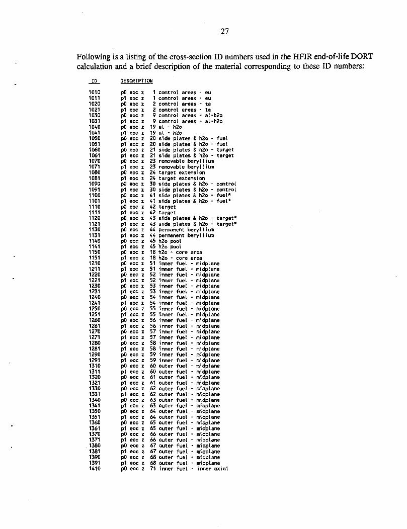
Following is a listing of the cross-section ID numbers used in the HFIR end-of-life DORT calculation and a brief description of the material corresponding to these ID numbers:
ID DESCRIPTION
1010 pO eoc z 1 control areas - eu 1011 p1 eoc z 1 control areas - eu 1020 pO eoc z 2 control areas - ta 1021 Pi eoc z 2 control areas - ta 1030 pO eoc z 9 control areas - al-h2o 1031 P1 eoc z 9 control areas - al-h2o 1040 pO eoc z 19 al - h2o 1041 P1 eoc z 19 al - h2o 1050 P0 eoc z 20 side plates & h2o - fuel 1051 p1 eoc z 20 side plates & h2o - fuel 1060 pO eoc z 21 side plates & h2o - target 1061 P1 eoc z 21 side plates & h2o - target 1070 pO eoc z 23 removable beryllium 1071 P1 eoc z 23 removable beryllium 1080 pO eoc z 24 target extension 1081 p1 eoc z 24 target extension 1090 PO eoc z 30 side plates & h2o - control 1091 p1 eoc z 30 side plates & h2o - control 1100 pO eoc z 41 side plates & h2o - fuel* 1101 p1 eoc z 41 side plates & h2o - fuel* 1110 pO eoc z 42 target 1111 p1 eoc z 42 target 1120 pO eoc z 43 side plates & h2o - target* 1121 p1 eoc z 43 side plates & h2o - target* 1130 pO eoc z 44 permanent beryllium 1131 p1 eoc z 44 permanent beryllium 1140 pO eoc z 45 h2o pool 1141 p1 eoc z 45 h2o pool 1150 PO eoc z 18 h2o - core area 1151 p1 eoc z 18 h2o - :ore area 1210 pO eoc z 51 inner :uel - midplane 1211 p1 eoc z 51 inner :uel - midplane 1220 pO eoc z 52 inner :uel - midplane 1221 p1 eoc z 52 inner :uel - midplane 1230 pO eoc z 53 inner :uel - midplane 1231 p1 eoc z 53 inner :uel - midplane 1240 pO eoc z 54 inner :uel - midplane 1241 p1 eoc z 54 inner :uel - midplane 1250 pO eoc z 55 inner :uel - nridplane 1251 p1 eoc z 55 inner :uel - midplane 1260 pO eoc z 56 inner :uel - midplane 1261 p1 eoc z 56 inner :uel - midplane 1270 pO eoc z 57 inner :uel - midplane 1271 p1 eoc z 57 inner :uel - midplane 1280 pO eoc z 58 inner fuel - midplane 1281 p1 eoc z 58 inner :uel - midplane 1290 pO eoc z 59 inner :uel - midplane 1291 p1 eoc z 59 inner fuel - midplane 1310 pO eoc z 60 outer fuel - midplane 1311 pi eoc z 60 outer cuel - midplane 1320 pO eoc z 61 outer :uel - midplane 1321 p1 eoc z 61 outer fuel - midplane 1330 pO eoc z 62 outer :uel - midplane 1331 p1 eoc z 62 outer Fuel - midplane 1340 pO eoc z 63 outer :uel - midplane 1341 p1 eoc z 63 outer =uel - midplane 1350 pO eoc z 64 outer Fuel - midplane 1351 p1 eoc z 64 outer fuel - midplane 1360 pO eoc z 65 outer !uel - midplane 1361 p1 eoc z 65 outer Fuel - midplane 1370 pO eoc z 66 outer Fuel - midplane 1371 p1 eoc z 66 outer Fuel - midplane 1380 pO eoc z 67 outer Fuel - midplane 1381 p1 eoc z 67 outer Fuel - midplane 1390 pO eoc z 68 outer Fuel - midplane 1391 p1 eoc z 68 outer Fuel - midplane 1410 pO eoc z 71 i nner Fuel - inner axial

28 1411 P1 eoc z 71 i nner • uel - inner axia 1420 P0 eoc z 72 i nner • uel - inner axia 1421 P1 eoc z 72 I nner • ue - inner axia 1430 pO eoc z 73 l nner ue - inner axia 1431 Pi eoc z 73 l nner • ue - inner axia 1440 PO eoc z 74 nner • Fue - inner axia 1441 P1 eoc z 74 nner • ue - inner axia 1450 pO eoc z 75 l nner • ue - inner axia 1451 p1 eoc z 75 i nner • ue! - inner axia 1460 pO eoc z 76 i nner • uel - inner axia 1461 p1 eoc z 76 l nner ue - inner axia 1470 pO eoc z 77 I nner • ue - inner axia 1471 p1 eoc z 77 nner • ue - inner axia 1480 pO eoc z 78 nner • ue - inner axia 1481 p1 eoc z 78 nner • ue - inner axia 1490 pO eoc z 79 I nner 1 ue - inner axia 1491 p1 eoc z 79 nner 1 ue - inner axia 1510 PO eoc z 80 outer 1 ue - inner axia 1511 pi eoc z 80 outer ue - inner axia 1520 PO eoc z 81 outer ue - inner axia 1521 p1 eoc z 81 outer ue - inner axia 1530 po eoc z 82 outer 1 ue - inner axia 1531 p1 eoc z 82 outer 1 ue - inner axia 1540 pO eoc z 83 outer ue - inner axia 1541 pi eoc z 83 outer 1 ue - i nner axia 1550 PO eoc z 84 outer ue - inner axia 1551 p1 eoc z 84 outer ue - inner axia 1560 PO eoc z 85 outer 1 ue - inner axia 1561 p1 eoc z 85 outer 1 ue - inner axia 1570 pO eoc z 86 outer 1 :ue - inner axia 1571 pi eoc z 86 outer 1 ue - inner axia 1580 pO eoc z 87 outer 1 :ue - inner axia 1581 p1 eoc z 87 suter 1 :ue - inner axia 1590 pO eoc z 88 suter 1 ue - inner axia 1591 pi eoc z 88 outer 1 ue - inner axia 1610 po eoc z 91 nner 1 ue - outer axia 1611 p1 eoc z 91 nner 1 ue - outer axia 1620 po eoc z 92 nner ue - outer axia 1621 p1 eoc z 92 nner ue - outer axia 1630 pO eoc z 93 nner 1 ue - outer axia 1631 p1 eoc z 93 nner ue - outer axia 1640 pO eoc z 94 nner 1 ue - outer axia 1641 p1 eoc z 94 nner 1 ue - outer axia 1650 po eoc z 95 inner 1 ue - outer axia 1651 p1 eoc z 95 nner 1 ue - outer axia 1660 po eoc z 96 nner 1 ue - outer axia 1661 p1 eoc z 96 nner ue - outer axia 1670 po eoc z 97 nner ue - outer axia 1671 p1 eoc z 97 nner ue - outer axia 1680 pO eoc z 98 nner 1 ue - outer axia 1681 p1 eoc z 98 nner 1 ue - outer axia 1690 po eoc z 99 inner ue - outer axia 1691 p1 eoc z 99 inner ue - outer axia 1710 pO eoc z 100 suter 1 ue - outer axia 1711 p1 eoc z 100 suter :ue - outer axia 1720 pO eoc z 101 suter :ue - outer axia 1721 p1 eoc z 101 suter :ue - outer axia 1730 pO eoc z 102 suter ue - outer axia 1731 p1 eoc z 102 suter ue - outer axia 1740 pO eoc z 103 suter ;ue - outer axia 1741 p1 eoc z 103 suter ue - outer axia 1750 po eoc z 104 suter :ue - outer axia 1751 p1 eoc z 104 suter ue - outer axia 1760 pO eoc z 105 suter 1 ue - outer axia 1761 p1 eoc z 105 ( suter 1 ue - outer axia 1770 pO eoc z 106 suter ue - outer axia 1771 pi eoc z 106 suter ue - outer axia 1780 pO eoc z 107 suter ue - outer axia 1781 pi eoc z 107 suter :ue - outer axia 1790 pO eoc z 108 suter ue - outer axia 1791 p1 eoc z 108 outer fue - outer axia

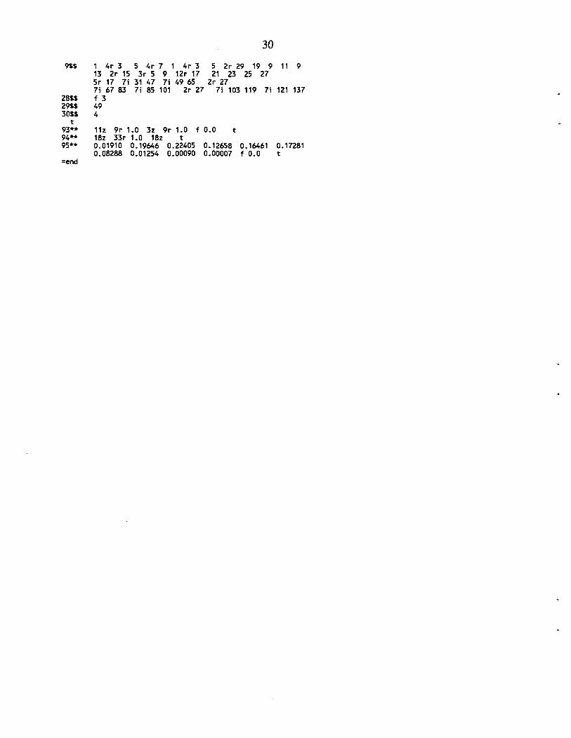
29
Following is the input listing for the discrete ordinates system required to run the DORT case for the HFIR end-of-life configuration described in this report: =gip hfir 1$$ 13$$
85 mwe r-z 39 3 28 1010 1011 1060 1061 1110 1111 1210 1211 1260 1261 1310 1311 1360 1361 1410 1411 1460 1461 1510 1511 1560 1561 1610 1611 1660 1661 1710 1711 1760 1761
model 67 1020 1070 1120 1220 1270 1320 1370 1420 1470 1520 1570 1620 1670 1720 1770
- eoc 0 0 1021 1071 1121 1221 1271 1321 1371 1421 1471 1521 1571 1621 1671 1721 1771
gip xs 138 138 1030 1031 1080 1081 1130 1131 1230 1231 1280 1281 1330 1331 1380 1381 1430 1431 1480 1481 1530 1531 1580 1581 1630 1631 1680 1681 1730 1731 1780 1781
0 1 1 1040 1041 1090 1091 1140 1141 1240 1241 1290 1291 1340 1341 1390 1391 1440 1441 1490 1491 1540 1541 1590 1591 1640 1641 1690 1691 1740 1741 1790 1791
10/04/91 0 2 e 1050 1051 1100 1101 1150 1151 1250 1251
1350 1351
1450 1451
1550 1551
1650 1651
1750 1751
t =dort hfir
61$$ 62$$
62$$ 62$$ 63** 63**
81** 82**
83** t 1**
2**
4**
31$$
32**
33**
34**
35*
85 mue r-z model 0 44 8 0 0 1 108 76 69 39 3 1 1 0 0 0 1 - 1 0 4 1 4z 0 -1 0 2r 1 0 5z a21 77 4s 2 2z 3 e s62 -1 400 400 1 e 144.0 1.0 1.0-4 1.0-6 a17 5.0-3 e
eoc k-calc - run 01 - base case e
28 67 1 0 e
1.0-6
0 2z
10/04/91
117 0 138 0 16
0.0 2r 8.3333-2 q3 q2 q8 -.47140 -.33333 .33333 -.94281 -.88192 -.33333 .33333 .88192 q8 3r -.88192 5r -.33333 3r .88192 5r .33333
0.01910 0.19646 0.22405 0.12658 0.16461 0.17281 0.08288 0.01254 0.00090 0.00007 f 0.0 9i -60.82 3i -37.55 3i -30.48 1i -25.40 1i -24.85 1i -22.75 20i -21.0 1i 21.0 1i 22.75 1i 24.85 3i 25.40 3i 30.48 9i 37.55 60.82 0.0 3i 0.887 3i 3.547 1i 6.40 7.14 7.15 4i 7.50 12.50 12.59 12.60 13.34 14.41 15.15 15.16 4i 15.50 20.50 20.99 21.00 21.7678 3i 22.0238 1i 22.6588 3i 22.9868 23.6218 23.9668 9i 24.1268 9i 32.9764 9i 53.9764 78.9764 1 2 6 16 12 11 17 18 2i 7 10 19 20 22 21 43 42 24 25 26 27 28 29 45 23 44 7i 51 59 7i 60 68 7i 71 79 7i 80 88 q18 7i 91 99 7i 100 108 q18 3r 22.0238 3r 22.9868 2r 0.0 2r 7.14 2r 15.15 12.60 6.40 21.00 3.547 0.0 0.887 2r 0.0 21.7678 22.6588 23.6218 23.9668 2r 24.1268 32.9764 7.14 7.15 4i 7.50 12.50 12.59 15.15 15.16 4i 15.50 20.50 20.99 4q18 3r 22.6588 3r 23.6218 2r 21.7678 2r 12.60 2r 21.00 15.15 7.14 0.887 3r 3.547 22.0238 22.9868 24.1268 78.9764 32.9764 7.15 4i 7.50 12.50 12.59 12.60 15.16 4i 15.50 20.50 20.99 21.00 4q18 -60.82 -37.55 -24.85 -60.82 24.85 37.55 -60.82 -30.40 25.40 q2 3r -30.40 3r -25.40 -37.55 25.40 3r -60.82 -60.82 2r -30.40 18r -25.40 18r -24.85 18r 22.75 18r -25.40 18r 24.85 -37.55 -24.85 60.82 24.85 37.55 60.82 -25.40 60.82 -25.40 30.40 q2 3r 30.40 3r 25.40 -25.40 37.55 2r 60.82 2r 60.82 60.82 2r 30.40 18r 22.75 18r -22.75 18r 24.85 18r -24.85 18r 25.40
21.7678 6.40 23.9668
53.9764
25.40 -60.82
30 9$$ 1 4r 3 5 4r 7 1 4r 3 5 2r 29 19 9 11 9
13 2r 15 3r 5 9 12r 17 21 23 25 27 5r 17 7i 31 47 7i 49 65 2r 27 7i 67 83 7i 85 101 2r 27 7i 103 119 7i 121 137
28$$ f 3 29$$ 49 30$$ 4
t 93** 11z 9r 1.0 3z 9r 1.0 f 0.0 t 94** 18z 33r 1.0 18z t 95** 0.01910 0.19646 0.22405 0.12658 0.16461 0.17281
0.08288 0.01254 0.00090 0.00007 f 0.0 t =end

31
Following is a listing of the cross-section ID numbers used in the HFIR xenon equilibrium DORT calculation and a brief description of the material corresponding to these ID numbers:
ID DESCRIPTION
1010 pO 29h z 1 control areas - eu 1011 P1 29h z 1 control areas - eu 1020 pO 29h z 2 control areas - ta 1021 P1 29h z 2 control areas - ta 1030 po 29h z 9 control areas - al-h2o 1031 p1 29h z 9 contro . areas - al-h2o 1040 pO 29h z 19 al - h2o 1041 p1 29h z 19 al - h2o 1050 pO 29h z 20 side plates & h2o - fuel 1051 p1 29h z 20 side plates & h2o - fuel 1060 pO 29h z 21 side plates & h2o - target 1061 P1 29h z 21 side plates & h2o - target 1070 pO 29h z 23 removable beryllium 1071 P1 29h z 23 removable beryllium 1080 pO 29h z 24 target extension 1081 P1 29h z 24 target extension 1090 pO 29h z 30 side plates & h2o - control 1091 p1 29h z 30 side plates & h2o - control 1100 pO 29h z 41 side plates & h2o - fuel* 1101 pi 29h z 41 side plates & h2o - fuel* 1110 pO 29h z 42 target 1111 p1 29h z 42 target 1120 po 29h z 43 side plates & h2o - target* 1121 p1 29h z 43 side plates & h2o - target* 1130 pO 29h z 44 permanent beryllium 1131 p1 29h z 44 permanent beryllium 1140 pO 29h z 45 h2o pool 1141 p1 29h z 45 h2o pool 1150 pO 29h z 18 h2o - core area 1151 p1 29h z 18 h2o - :ore area 1210 pO 29h z 51 inner :uel - midplane 1211 p1 29h z 51 inner :uel - midplane 1220 pO 29h z 52 inner :uel - midplane 1221 p1 29h z 52 inner :uel - midplane 1230 po 29h z 53 inner :uel - midplane 1231 p1 29h z 53 inner !uel - midplane 1240 pO 29h z 54 inner :uel - midplane 1241 p1 29h z 54 inner :uel - midplane 1250 po 29h z 55 inner fuel - midplane 1251 p1 29h z 55 inner :uel - midplane 1260 pO 29h z 56 inner :uel - midplane 1261 p1 29h z 56 inner :uel - midplane 1270 pO 29h z 57 inner :uel - midplane 1271 p1 29h z 57 inner !uel - midplane 1280 pO 29h z 58 inner :uel - midplane 1281 p1 29h z 58 inner fuel - midplane 1290 po 29h z 59 inner Fuel - midplane 1291 p1 29h z 59 inner :uel - midplane 1310 pO 29h z 60 outer :uel - midplane 1311 p1 29h z 60 outer fuel - midplane 1320 pO 29h z 61 outer :uel - midplane 1321 p1 29h z 61 outer fuel - midplane 1330 pO 29h z 62 outer Euel - midplane 1331 p1 29h z 62 outer fuel - midplane 1340 pO 29h z 63 outer fuel - midplane 1341 p1 29h z 63 outer :uel - midplane 1350 pO 29h z 64 outer fuel - midplane 1351 p1 29h z 64 outer fuel - midplane 1360 pO 29h z 65 outer fuel - midplane 1361 p1 29h z 65 outer Fuel - midplane 1370 po 29h z 66 outer Fuel - midplane 1371 p1 29h z 66 outer Fuel - midplane 1380 po 29h z 67 outer Fuel - midplane 1381 p1 29h z 67 outer :ue( - midplane 1390 pO 29h z 68 outer fuel - midplane

32
1391 Pi 29h z 68 outer • uel - midplane 1410 p0 29h z 71 inner • uel - inner axial 1411 p1 29h z 71 inner • uel - inner axial 1420 pO 29h z 72 inner • uel - inner axial 1421 p1 29h z 72 inner • uel - inner axial 1430 pO 29h z 73 inner uel - inner axial 1431 p1 29h z 73 inner uel - inner axial 1440 pO 29h z 74 inner 1 uel - inner axial 1441 p1 29h z 74 inner uel - inner axial 1450 pO 29h z 75 inner 1 uel - inner axial 1451 p1 29h z 75 inner uel - inner axial 1460 PO 29h z 76 inner uel - inner axial 1461 p1 29h z 76 inner uel - inner axial 1470 pO 29h z 77 inner 1 uel - inner axial 1471 p1 29h z 77 inner uel - inner axial 1480 pO 29h z 78 inner uel - inner axial 1481 p1 29h z 78 inner uel - inner axial 1490 pO 29h z 79 inner 1 uel - inner axial 1491 p1 29h z 79 inner uel - inner axial 1510 pO 29h z 80 outer 1 uel - inner axial 1511 p1 29h z 80 outer uel - inner axial 1520 pO 29h z 81 outer uel - inner axial 1521 p1 29h z 81 outer 1 uel - inner axial 1530 pO 29h z 82 outer 1 uel - inner axial 1531 pi 29h z 82 outer 1 uel - inner axial 1540 pO 29h z 83 outer 1 uel - inner axial 1541 p1 29h z 83 outer 1 uel - inner axial 1550 pO 29h z 84 outer 1 uel - inner axial 1551 pi 29h z 84 outer 1 uel - inner axial 1560 pO 29h z 85 outer 1 uel - inner axial 1561 p1 29h z 85 outer uel - inner axial 1570 pO 29h z 86 outer 1 uel - inner axial 1571 p1 29h z 86 outer 1 uel - inner axial 1580 po 29h z 87 outer 1 uel - inner axial 1581 p1 29h z 87 outer 1 uel - inner axial 1590 pO 29h z 88 outer 1 'uel - inner axial 1591 p1 29h z 88 outer uel - inner axial 1610 pO 29h z 91 inner uel - outer axial 1611 p1 29h z 91 inner uel - outer axial 1620 pO 29h z 92 inner 1 uel - outer axial 1621 p1 29h z 92 inner uel - outer axial 1630 pO 29h z 93 inner uel - outer axial 1631 p1 29h z 93 inner uel - outer axial 1640 pO 29h z 94 inner uel - outer axial 1641 p1 29h z 94 inner uel - outer axial 1650 pO 29h z 95 inner 1 ;uel - outer axial 1651 p1 29h z 95 inner 1 uel - outer axial 1660 pO 29h z 96 inner 1 uel - outer axial 1661 p1 29h z 96 inner 1 uel - outer axial 1670 pO 29h z 97 inner 1 uel - outer axial 1671 p1 29h z 97 inner 1 uel - outer axial 1680 pO 29h z 98 inner 1 uel - outer axial 1681 p1 29h z 98 inner 1 uel - outer axial 1690 pO 29h z 99 inner 1 uel - outer axial 1691 p1 29h z 99 inner 1 uel - outer axial 1710 pO 29h z 100 outer 1 uel - outer axial 1711 p1 29h z 100 outer 1 uel - outer axial 1720 po 29h z 101 outer 1 uel - outer axial 1721 p1 29h z 101 outer 1 uel - outer axial 1730 pO 29h z 102 outer 1 uel - outer axial 1731 p1 29h z 102 outer uel - outer axial 1740 pO 29h z 103 outer uel - outer axial 1741 p1 29h z 103 outer uel - outer axial 1750 pO 29h z 104 outer :uel - outer axial 1751 p1 29h z 104 outer :uel - outer axial 1760 pO 29h z 105 outer :uel - outer axial 1761 p1 29h z 105 outer :uel - outer axial 1770 pO 29h z 106 outer uel - outer axial 1771 p1 29h z 106 outer :uel - outer axial 1780 pO 29h z 107 outer :uel - outer axial 1781 p1 29h z 107 outer uel - outer axial 1790 pO 29h z 108 outer uel - outer axial 1791 p1 29h z 108 outer :uel - outer axial

33
Following is the input listing for the discrete ordinates system required to run the DORT case for the HFIR xenon equilibrium configuration described in this report: =gip hfir 1$$ 13$$
85 mwe r-z 39 3 28 1010 1011 1060 1061 1110 1111 1210 1211 1260 1261 1310 1311 1360 1361 1410 1411 1460 1461 1510 1511 1560 1561 1610 1611 1660 1661 1710 1711 1760 1761
model 67 1020 1070 1120 1220 1270 1320 1370 1420 1470 1520 1570 1620 1670 1720 1770
- 29 hrs(1. 0 0 138 1021 1030 1071 1080 1121 1130 1221 1230 1271 1280 1321 1330 1371 1380 1421 1430 1471 1480 1521 1530 1571 1580 1621 1630 1671 1680 1721 1730 1771 1780
2 days) gip x-s 138 1031 1081 1131 1231 1281 1331 1381 1431 1481 1531 1581 1631 1681 1731 1781
0 1 1 1040 1041 1090 1091 1140 1141 1240 1241 1290 1291 1340 1341 1390 1391 1440 1441 1490 1491 1540 1541 1590 1591 1640 1641 1690 1691 1740 1741 1790 1791
11/26/91 0 2 e t 1050 1051 1100 1101 1150 1151 1250 1251
1350 1351
1450 1451
1550 1551
1650 1651
1750 1751
t =dort hfir
61$$ 62$$
62$$ 62$$ 63** 63**
11/26/91
138 0 16
81** 82** 83**
t 1**
2**
4**
31$$
32**
33**
34**
35**
-9.0
.50 12.50 20.50
85 mwe r-z model - 29h k-calc - run 01 - 296k h be 0 44 8 0 e 0 1 108 76 71 39 3 28 67 0 117 0
1 1 0 0 0 1 - 1 0 4 1 1 0 2 z 0 4z 0 -1 0 2r 1 0 5z e a21 77 4s 2 2z 3 e a62 -1 400 400 1 e 144.0 1.0 1.0-4 1.0-6 1.0-6 e a17 5.0-3 e
0.0 2r 8.3333-2 q3 q2 q8 -.47140 -.33333 .33333 -.94281 -.88192 -.33333 .33333 .88192 q8 3r -.88192 5r -.33333 3r .88192 5r .33333 0.01910 0.19646 0.22405 0.12658 0.16461 0.17281 0.08288 0.01254 0.00090 0.00007 f 0.0 9i -60.82 3i -37.55 3i -30.48 1i -25.40 1i -24.85 1i -22.75 4i -21.0 -11.0 -10.05 8i 9.0 10.05 4i 11.0 1i 21.0 1i 22.75 1i 24.85 3i 25.40 3i 30.48 9i 37.55 60.82 0.0 3i 0.887 3i 3.547 1i 6.40 7.14 7.15 4i 7 12.59 12.60 13.34 14.41 15.15 15.16 4i 15.50 20.99 21.00 21.7678 3i 22.0238 1i 22.6588 3i 22.9868 23.6218 23.9668 9i 24.1268 9i 32.9764 9i 53.9764 78.9764 1 2 6 16 12 11 17 18 2i 7 10 19 20 22 21 43 42 24 25 26 27 28 29 45 23 44 7i 51 59 7i 60 68 7i 71 79 7i 80 88 q18 7i 91 99 7i 100 108 q18 3r 22.0238 3r 22.9868 2r 0.0 2r 7.14 2r 15.15 12.60 6.40 21.00 3.547 0.0 0.887 2r 0.0 21.7678 22.6588 23.6218 23.9668 2r 24.1268 32.9764 7.14 7.15 4i 7.50 12.50 12.59 15.15 15.16 4i 15.50 20.50 20.99 4q18 3r 22.6588 3r 23.6218 2r 21.7678 2r 12.60 2r 21.00 15.15 7.14 21.7678 6.40 0.887 3r 3.547 22.0238 22.9868 24.1268 78.9764 32.9764 53.9764 7.15 4i 7.50 12.50 12.59 12.60 15.16 4i 15.50 20.50 20.99 21.00 4q18 -60.82 -22.75 -10.05 -60.82 10.05 22.75 -60.82 -30.40 25.40 q2 3r -30.40 3r -25.40 -37.55 25.40 3r -60.82 -60.82 2r -30.40 18r -25.40 18r -24.85 18r 22.75 18r -25.40 18r 24.85 -22.75 -10.05 60.82 10.05 22.75 60.82 -25.40 60.82 -25.40 30.40 q2 3r 30.40 3r 25.40 -25.40 37.55 2r 60.82 2r 60.82 60.82 2r 30.40 18r 22.75
23.9668
25.40 -60.82

34 18r -22.75 18r 24.85 18r -24.85 18r 25.40
9$$ 1 4r 3 5 4r 7 1 4r 3 5 2r 29 19 9 11 9 13 2r 15 3r 5 9 12r 17 21 23 25 27 5r 17 7i 31 47 7i 49 65 2r 27 7i 67 83 7i 85 101 2r 27 7i 103 119 7i 121 137
28$$ f 3 29$$ 49 30$$ 4 t
93** 11z 9r 1.0 3z 9r 1.0 f 0.0 t 94** 18z 35r 1.0 18z t 95** 0.01910 0.19646 0.22405 0.12658 0.16461 0.17281
0.08288 0.01254 0.00090 0.00007 f 0.0 t =end

ORNL/TM-12386
INTERNAL DISTRIBUTION
1. J. A. Bucholz 2-6. W. W. Engle, Jr.
7. H. A. Glover 8. H. T. Hunter 9. D. T. Ingersoll 10. G. E. Michaels 11. C. E. Oliver 12. J. V. Pace, III
13-17. R. B. Rothrock 18. C. O. Slater 19. R. R. Spencer
20. R. C. Ward 21. J. D. White
22-26. L. R. Williams 27-28. Laboratory Records
Department 29. Laboratory Records,
ORNL-RC 30. Document Reference
Section 31. Central Research Library 32. ORNL Patent Section
EXTERNAL DISTRIBUTION
33. R. A. Hunter, Director of Facilities, Fuel Cycle and Test Programs, Office of Nuclear Energy, NE-47, F-424/GTN, Department of Energy, Washington, D. C. 20585
34. Matthew A. Hutmaker, Jr., Office of Nuclear Energy, NE-47, GTN, Department of Energy, Washington, D. C. 20585.
35. William F. Manning, Deputy Assistant Manager, Energy Research and Development, Advanced-Neutron Source, Department of Energy, Oak Ridge Operations, P. O. Box 2001, Oak Ridge, Tennessee 37831-8218.
36. Barry S. Willis, Director, Research Operations Division, Department of Energy, Oak Ridge Operations, Post Office Box 2008, Oak Ridge, Tennessee 37831-6300.
37-38. Office of Scientific and Technical Information, U.S. Department of Energy, P.O. Box 62, Oak Ridge, Tennessee 37831.
39. Assistant Manager of Energy Research and Development, DOE-ORO, P.O. Box 2008 Oak Ridge TN 37831-6269