
TELSTRA IP TELEPHONY - WordPress.com...Figure 1 – Telstra IP Telephony (TIPT) Overview TIPT...
39
TIPT Customer Integration Guide | August 2013 Page 1 of 39 TELSTRA IP TELEPHONY CUSTOMER DETAILED INTEGRATION GUIDE
Transcript of TELSTRA IP TELEPHONY - WordPress.com...Figure 1 – Telstra IP Telephony (TIPT) Overview TIPT...
TIPT Customer Integration Guide | August 2013 Page 1 of 39
TELSTRA IP TELEPHONY CUSTOMER DETAILED INTEGRATION GUIDE
TIPT Customer Integration Guide | August 2013 Page 2 of 39
1. About this Document .................................................................................................................5
1.1. Introduction .....................................................................................................................5
1.2. Minimum customer environment ....................................................................................5
1.3. Overview of the Telstra IP Telephony network ................................................................6
2. Customer Integration ................................................................................................................7
2.1. Contents ..........................................................................................................................7
2.2. Disclaimer .......................................................................................................................7
2.3. IP Routing .......................................................................................................................7
2.3.1. Introduction ..................................................................................................................7
2.3.2. Interconnects ................................................................................................................8
2.3.3. Interconnect Configuration ......................................................................................... 11
2.4. LAN Environment .......................................................................................................... 11
2.4.1. LAN switches ............................................................................................................. 11
2.4.2. WAN router ............................................................................................................... 12
2.4.3. Switch port ................................................................................................................ 12
2.4.4. Legacy switches ........................................................................................................ 13
2.4.5. Testing requirements ................................................................................................. 13
2.4.6. Disclaimer ................................................................................................................. 13
2.5. Cabling ......................................................................................................................... 13
2.5.1. Customer cabling ...................................................................................................... 13
2.6. VLANs .......................................................................................................................... 13
2.6.1. Voice VLAN ............................................................................................................... 13
2.7. VLAN allocation ........................................................................................................... 15
2.7.1. Cisco environment using CDP .................................................................................. 15
2.7.2. Non Cisco environments without CDP (LLDP) ......................................................... 15
2.8. Power over Ethernet (PoE) .......................................................................................... 15
2.8.1. Using PoE ................................................................................................................. 15
2.8.2. AC Power Packs ....................................................................................................... 16
2.9. Network Time Protocol (NTP) ...................................................................................... 16
TIPT Customer Integration Guide | August 2013 Page 3 of 39
2.9.1. Using NTP ................................................................................................................. 16
2.10. DHCP Server ............................................................................................................. 16
2.10.1. Configuring DHCP server ....................................................................................... 16
2.10.2. DHCP options ......................................................................................................... 17
2.10.3. Testing before the phone boot process ................................................................... 17
2.10.4. Cisco IOS DHCP server .......................................................................................... 18
2.10.5. Microsoft Windows DHCP server ............................................................................ 18
2.11. DNS Server ................................................................................................................ 20
2.11.1. Configuring the DNS server .................................................................................... 20
2.11.2. Integrating the on-site DNS ..................................................................................... 20
2.11.3. DNS name value validation ..................................................................................... 21
2.12. Web Proxy (Caching) Server ..................................................................................... 21
2.12.1. Configuring the caching server ............................................................................... 21
2.13. Firewalls ..................................................................................................................... 21
2.13.1. TIPT and firewalls ................................................................................................... 21
2.14. Quality of Service (QoS) ............................................................................................ 22
2.14.1. Introduction ............................................................................................................. 22
2.14.2. Class of Service ...................................................................................................... 23
2.15. CPE Device Configuration Delivery ........................................................................... 23
2.15.1. Hosted configuration server .................................................................................... 23
2.15.2. Device Management Solution ................................................................................. 23
2.15.3. Phone install procedure with QSetup ..................................................................... 24
2.15.4. Adds, Moves and Changes ..................................................................................... 24
2.16. IP Handsets –Polycom IP Phones ............................................................................. 24
2.16.1. Available models ..................................................................................................... 24
2.16.2. Polycom configurations and diagnostics ................................................................. 25
2.16.3. VLANID ................................................................................................................... 26
2.17. Integrated Access Devices – Linksys IADs ................................................................ 26
2.17.1. Configuring the Linksys IAD.................................................................................... 26
2.18. Soft Client – Mobile and PC – UC-One ..................................................................... 27
2.18.1. Connectivity Requirements for Desktop Client ....................................................... 27
TIPT Customer Integration Guide | August 2013 Page 4 of 39
2.18.2. Connectivity Requirements for Mobile Client .......................................................... 27
2.18.3. Port Requirements .................................................................................................. 27
2.18.4. Quality of service for UC-One clients (QoS) ........................................................... 27
3. BRIX Verifier and Reporting ................................................................................................... 28
3.1. Introduction .................................................................................................................. 28
3.1.1. Operational status ..................................................................................................... 28
3.1.2. Pre-commissioning requirement ............................................................................... 28
4. Floor Plan (Professional Installation) ..................................................................................... 28
4.1. Preparing for installation .............................................................................................. 28
5. Desktop Integration ................................................................................................................ 29
5.1. Introduction .................................................................................................................. 29
5.2. Telstra Telephony Toolbar (TTT) .................................................................................. 29
5.2.1. Downloading the TTT ................................................................................................ 29
5.2.2. Installation, Integration and deployment ................................................................... 29
5.2.3. TTT features .............................................................................................................. 30
5.2.4. TTT Tags ................................................................................................................... 30
5.3. miRECEPTION ............................................................................................................ 31
5.3.1. Requirements ............................................................................................................ 31
5.3.2. Installation and configuration instructions ................................................................. 32
6. Miscellaneous Integration ...................................................................................................... 32
6.1. Introduction .................................................................................................................. 32
6.2. Music on Hold (MoH) ................................................................................................... 32
6.2.1. Music on Hold Customisation ................................................................................... 32
6.3. Headsets ...................................................................................................................... 32
7. Reception Solutions ............................................................................................................... 33
7.1. Simple Reception Solution........................................................................................... 33
7.2. Premium Reception Solution ....................................................................................... 33
8. Appendices ............................................................................................................................ 34
8.1. Appendix A: Glossary ................................................................................................. 34
8.2. Appendix B: TIPT CPE Troubleshooting & Quick Tips ................................................ 36
8.2.1. CPE configuration & troubleshooting ........................................................................ 36
TIPT Customer Integration Guide | August 2013 Page 5 of 39
8.2.2. CPE quick tips ........................................................................................................... 39
This document is designed to assist the customer with its TIPT integration, training and deployment activities. Additional troubleshooting and tips are provided in the Appendix of this document.
Note: This document does not constitute an IP Tel design but serves as a generic reference guide for the adoption of the TIPT Hosted suite of products and applications only within the customer’s environment.
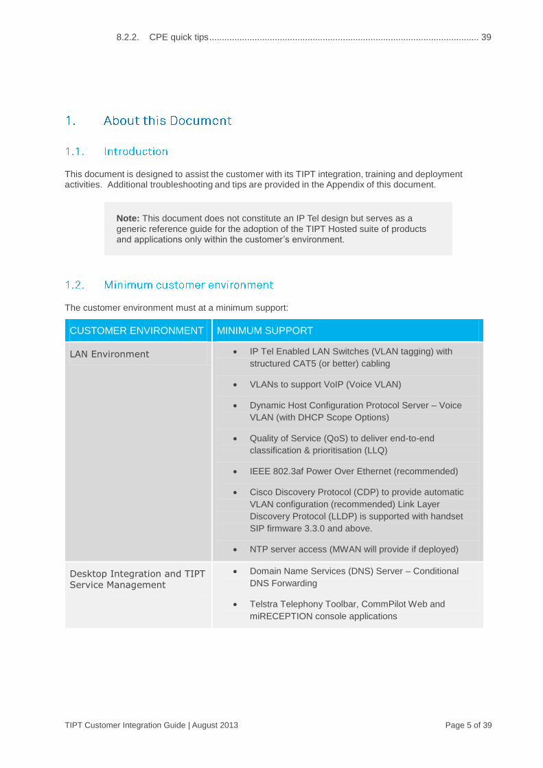
The customer environment must at a minimum support:
CUSTOMER ENVIRONMENT MINIMUM SUPPORT
LAN Environment IP Tel Enabled LAN Switches (VLAN tagging) with
structured CAT5 (or better) cabling
VLANs to support VoIP (Voice VLAN)
Dynamic Host Configuration Protocol Server – Voice
VLAN (with DHCP Scope Options)
Quality of Service (QoS) to deliver end-to-end
classification & prioritisation (LLQ)
IEEE 802.3af Power Over Ethernet (recommended)
Cisco Discovery Protocol (CDP) to provide automatic
VLAN configuration (recommended) Link Layer
Discovery Protocol (LLDP) is supported with handset
SIP firmware 3.3.0 and above.
NTP server access (MWAN will provide if deployed)
Desktop Integration and TIPT
Service Management
Domain Name Services (DNS) Server – Conditional
DNS Forwarding
Telstra Telephony Toolbar, CommPilot Web and
miRECEPTION console applications

TIPT Customer Integration Guide | August 2013 Page 6 of 39
The diagram below provides an overview of the Telstra IP Telephony construct.
Figure 1 – Telstra IP Telephony (TIPT) Overview

TIPT Customer Integration Guide | August 2013 Page 7 of 39
The following sections provide customer integration information to support the TIPT solution. Specifically the customer must configure and validate the following:
ITEM DETAILS
IP Routing
LAN environment Cabling
VLANS (VoIP VLAN)
Power over Ethernet (PoE)
NTP Server
DHCP Server (VoIP VLAN)
DNS Server
Firewalls
Quality of Service (QoS)
Web Proxy (Caching) Server
CPE Device Configuration
Delivery
Polycom IP Phones
Integrated Access Devices
(IADs)
BRIX Verifier
SIP Ping (SipSak Testing
Tool)
Floor Plan (Professional
Installation)
This guide is not intended to detail customer specific IP Telephony requirements. Refer to Telstra specific configuration (that is: Customer Design).
Telstra requires that the customer has interconnects to the TIPT platform from the customer’s Telstra IP-VPN as per the figure below. Connectivity is via the private IP network and not via the Internet.

TIPT Customer Integration Guide | August 2013 Page 8 of 39
Figure 2 – TIPT Interconnects
Two data interconnects located in Melbourne and Sydney for access to the TIPT application server clusters are required as well as at least one Media interconnect per State dependant on customer requirements. Voice signalling and RTP streams (off-net) are routed via the TIPT Session Border Controllers (SBC) which are deployed in a High Availability, Stateful, Active / Standby configuration and provide Network Address Translation (NAT) and Voice firewall services.
The customer must be able to route to these networks to reach the TIPT platform. IP routing can be configured via static or dynamic routing protocols at the customer edge device (BGP is preferred).
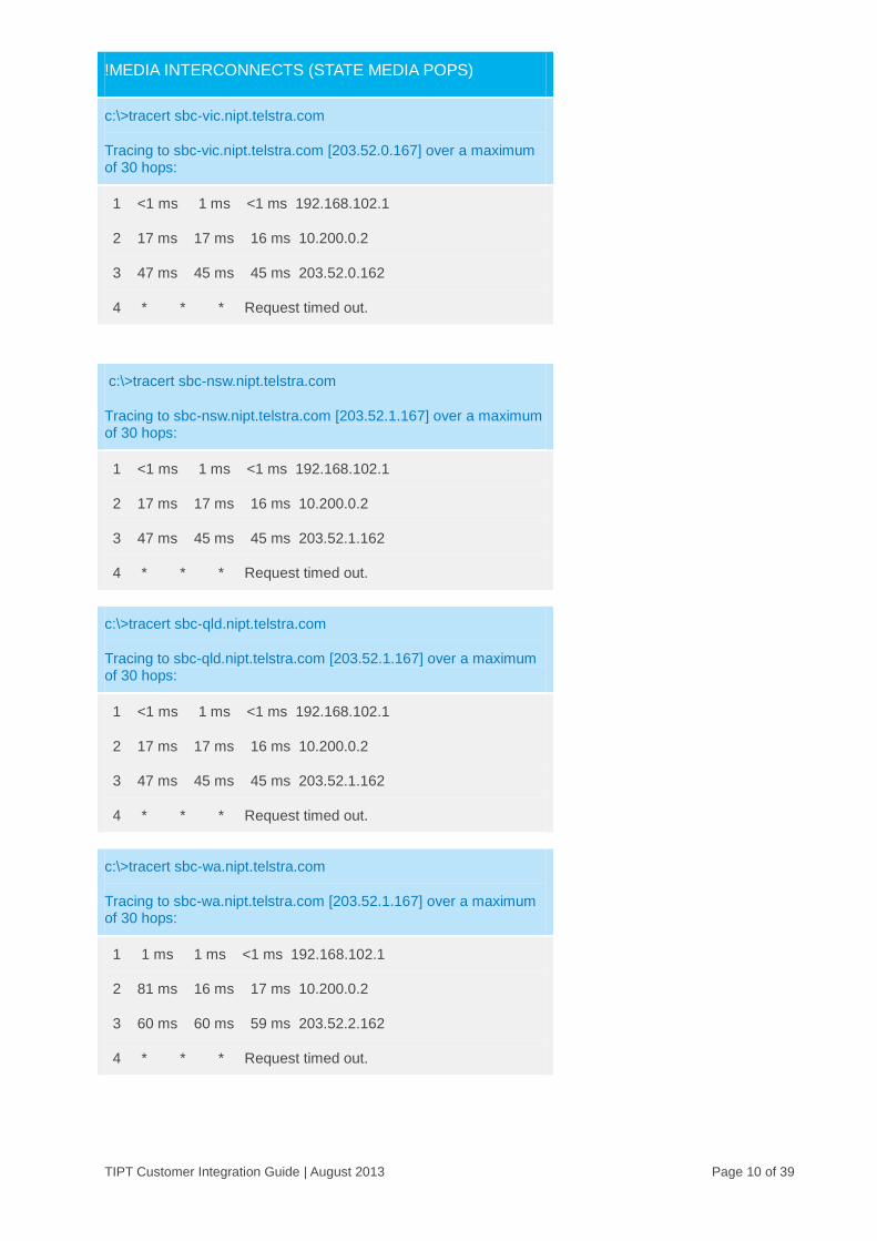
A traceroute to these hosts should be performed prior to deployment. The traceroute will only show the first few hops as per sample below as ICMP is blocked inside the Telstra core. IP routing to these interconnects (POPs) must not occur via the Internet or via third party data-centres.
!DNS SERVERS (VIC & NSW DATA POPS)
c:\>tracert -d 203.52.0.221
Tracing to 203.52.0.221 over a maximum of 30 hops:
1 <1 ms 1 ms <1 ms 192.168.102.1
2 16 ms 17 ms 17 ms 10.200.0.2
3 18 ms 18 ms 18 ms 10.86.64.17
4 18 ms 18 ms 18 ms 10.86.64.18
5 * * * Request timed out.

TIPT Customer Integration Guide | August 2013 Page 9 of 39
c:\>tracert -d 203.52.1.222
Tracing to 203.52.1.222 over a maximum of 30 hops:
1 1 ms 1 ms <1 ms 192.168.102.1
2 15 ms 16 ms 15 ms 10.200.0.2
3 31 ms 31 ms 32 ms 10.86.65.17
4 31 ms 31 ms 32 ms 10.86.65.18
5 * * * Request timed out.
!WEB SERVERS(VIC & NSW DATA POPS)
c:\>tracert -d 144.140.208.81
Tracing to 144.140.208.81over a maximum of 30 hops:
1 <1 ms 1 ms <1 ms 192.168.102.1
2 16 ms 17 ms 17 ms 10.200.0.2
3 18 ms 18 ms 18 ms 10.86.64.17
4 18 ms 18 ms 18 ms 10.86.64.18
5 * * * Request timed out.
c:\>tracert -d 144.140.181.80
Tracing to 144.140.181.80 over a maximum of 30 hops:
1 <1 ms 1 ms <1 ms 192.168.102.1
2 16 ms 17 ms 17 ms 10.200.0.2
3 18 ms 18 ms 18 ms 10.86.64.17
4 18 ms 18 ms 18 ms 10.86.64.18
5 * * * Request timed out.
TIPT Customer Integration Guide | August 2013 Page 10 of 39
!MEDIA INTERCONNECTS (STATE MEDIA POPS)
c:\>tracert sbc-vic.nipt.telstra.com
Tracing to sbc-vic.nipt.telstra.com [203.52.0.167] over a maximum of 30 hops:
1 <1 ms 1 ms <1 ms 192.168.102.1
2 17 ms 17 ms 16 ms 10.200.0.2
3 47 ms 45 ms 45 ms 203.52.0.162
4 * * * Request timed out.
c:\>tracert sbc-nsw.nipt.telstra.com
Tracing to sbc-nsw.nipt.telstra.com [203.52.1.167] over a maximum of 30 hops:
1 <1 ms 1 ms <1 ms 192.168.102.1
2 17 ms 17 ms 16 ms 10.200.0.2
3 47 ms 45 ms 45 ms 203.52.1.162
4 * * * Request timed out.
c:\>tracert sbc-qld.nipt.telstra.com
Tracing to sbc-qld.nipt.telstra.com [203.52.1.167] over a maximum of 30 hops:
1 <1 ms 1 ms <1 ms 192.168.102.1
2 17 ms 17 ms 16 ms 10.200.0.2
3 47 ms 45 ms 45 ms 203.52.1.162
4 * * * Request timed out.
c:\>tracert sbc-wa.nipt.telstra.com
Tracing to sbc-wa.nipt.telstra.com [203.52.1.167] over a maximum of 30 hops:
1 1 ms 1 ms <1 ms 192.168.102.1
2 81 ms 16 ms 17 ms 10.200.0.2
3 60 ms 60 ms 59 ms 203.52.2.162
4 * * * Request timed out.

TIPT Customer Integration Guide | August 2013 Page 11 of 39
The table below shows the configuration for the Data, Media and AS interconnects.
INTERCONNECTS CONFIGURATION DESCRIPTION
Data interconnects (Mandatory)
203.52.0.0/23 Kent St and Lonsdale St – Media and Data
203.41.188.96/28 Lonsdale St – TIPT Web Servers
203.42.70.224/28 Kent St Data – TIPT Web Servers
144.140.208.16/29 Exhibition St – Digital Business
144.140.208.32/28 Exhibition St – TIPT DMS
144.140.208.80/28 Exhibition St – TIPT Web Servers
144.140.162.40/29 Pitt St – Digital Business
144.140.162.48/28 Pitt St – TIPT DMS
144.140.162.80/28 Pitt St – TIPT Web Servers
144.140.181.80/28 St Leonards – TIPT Web Servers
Media interconnects (As required)
203.52.0.0/24 Victoria – SBC
203.52.1.0/24 NSW – SBC
203.52.3.160/28 Queensland – SBC
203.44.43.160/28 South Australia – SBC
203.52.2.160/28 Western Australia – SBC
203.44.44.160/28 ACT – SBC
203.44.42.0/27 Northern Territory – SBC
203.44.42.224/27 Tasmania – SBC
Table 1 – TIPT Interconnects (Data & Media POPs)
IP Telephony enabled LAN switches supporting VLANs, IEEE8021.Q (VLAN Tagging), IEEE 802.3af (Power over Ethernet), Quality of Service (QoS) must be used. VLAN segmentation is required to demarcate and allow prioritisation of voice traffic. VLAN ID 100 is recommended as the Voice VLAN to ensure configuration consistency across all sites. PC’s will typically piggy-back from the IP Phone but reside in the Data VLAN (that is: VLAN ID 1).
The use of Cisco switches with CDP provides automatic VLAN assignment of Polycom IP Phones where Voice VLAN’s have been configured. In non-Cisco LAN switch environments the VLAN ID (that is: VLAN 100) will need to be manually configured in each IP handset unless the IP handset has SIP firmware 3.3.0 or above where there is support for LLDP.
TIPT Customer Integration Guide | August 2013 Page 12 of 39
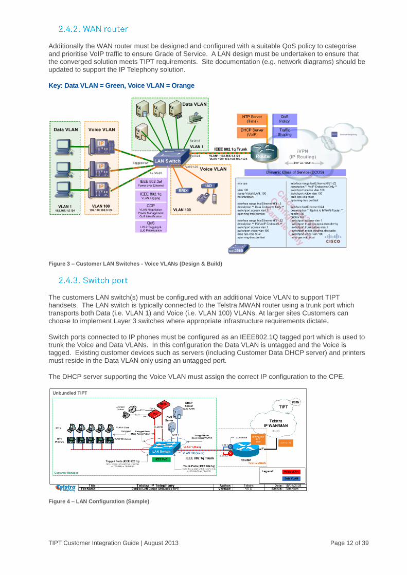
Additionally the WAN router must be designed and configured with a suitable QoS policy to categorise and prioritise VoIP traffic to ensure Grade of Service. A LAN design must be undertaken to ensure that the converged solution meets TIPT requirements. Site documentation (e.g. network diagrams) should be updated to support the IP Telephony solution.
Key: Data VLAN = Green, Voice VLAN = Orange
Figure 3 – Customer LAN Switches - Voice VLANs (Design & Build)
The customers LAN switch(s) must be configured with an additional Voice VLAN to support TIPT handsets. The LAN switch is typically connected to the Telstra MWAN router using a trunk port which transports both Data (i.e. VLAN 1) and Voice (i.e. VLAN 100) VLANs. At larger sites Customers can choose to implement Layer 3 switches where appropriate infrastructure requirements dictate.
Switch ports connected to IP phones must be configured as an IEEE802.1Q tagged port which is used to trunk the Voice and Data VLANs. In this configuration the Data VLAN is untagged and the Voice is tagged. Existing customer devices such as servers (including Customer Data DHCP server) and printers must reside in the Data VLAN only using an untagged port.
The DHCP server supporting the Voice VLAN must assign the correct IP configuration to the CPE.
Figure 4 – LAN Configuration (Sample)

TIPT Customer Integration Guide | August 2013 Page 13 of 39
Specialist equipment including Integrated Analogue Devices (IADs) and BRIX verifiers must be connected directly into the Voice VLAN as per sample figure 5 below.
At least 1 x LAN switch-port is required to be configured into the Voice VLAN for management (diagnostic\troubleshooting) purposes.
Note: These devices will not function correctly if connected via the Data VLAN.
The customer should pay close attention to legacy switches (non-Cisco) or switches located in remote buildings which may not present VLAN or PoE to its intended location.
The LAN build (including DHCP) must be completed and tested (Voice & Data) at each location prior to IP handset/IAD deployment. This includes testing both IP Phone and PC connectivity at all locations and across all access switches prior to deployment.
Customer specific IP Tel LAN design is outside the scope of this document.
The customers LAN must have structured cabling of CAT5 or better in order to support IP Telephony. Enterprise grade IP Telephony places higher requirements on network cabling and LAN infrastructure.
All cabling including network patching is the responsibility of the customer and must be completed before the on-site arrival of professional phone installers.
Figure 5 – Cabling & Network Patching Requirements
VLANs are required to segment and provide grade of service to IP Phones. The use of a separate Voice VLAN for VoIP is essential for all deployments of IP Telephony. VLAN configuration and validation must be performed prior to IP handset deployment.
The Voice VLAN ports are nominally configured as IEEE802.1Q tagged and the Data VLAN ports configured as untagged. This allows the IP Phone to reside in the Voice VLAN whilst the PC resides in the Data network (e.g. VLAN 1). Printers and Servers must remain in the Data VLAN.
TIPT Customer Integration Guide | August 2013 Page 14 of 39
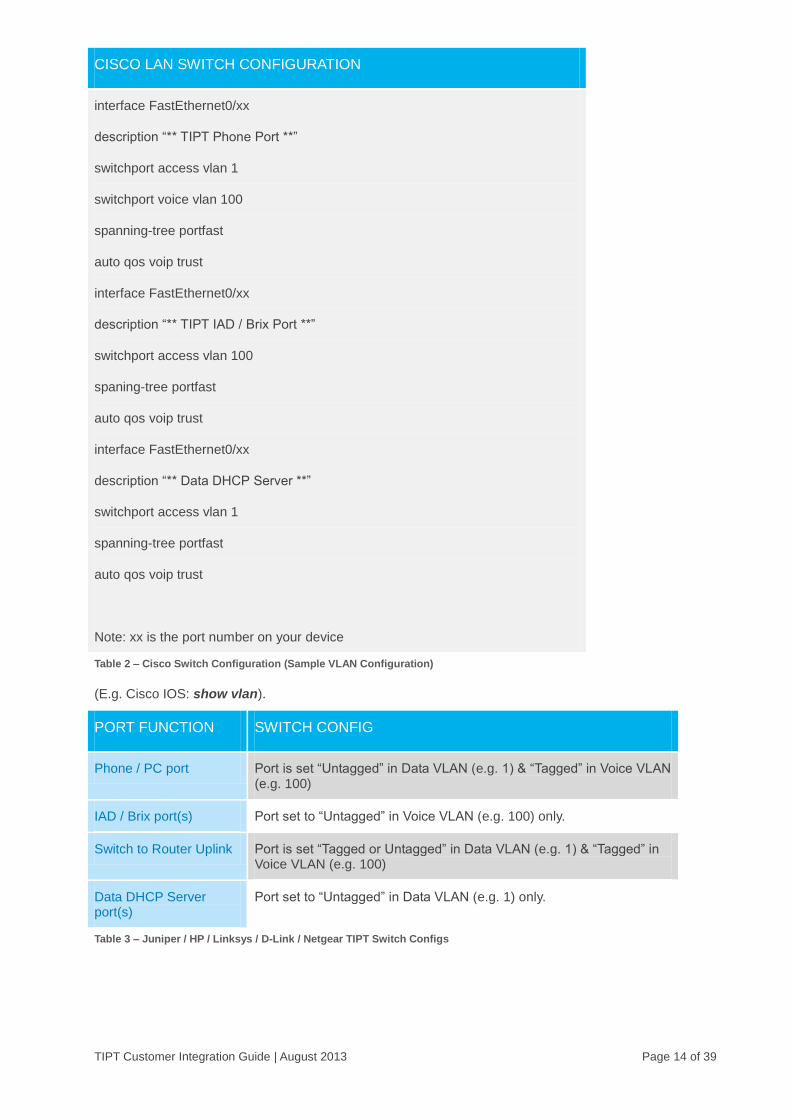
CISCO LAN SWITCH CONFIGURATION
interface FastEthernet0/xx
description “** TIPT Phone Port **”
switchport access vlan 1
switchport voice vlan 100
spanning-tree portfast
auto qos voip trust
interface FastEthernet0/xx
description “** TIPT IAD / Brix Port **”
switchport access vlan 100
spaning-tree portfast
auto qos voip trust
interface FastEthernet0/xx
description “** Data DHCP Server **”
switchport access vlan 1
spanning-tree portfast
auto qos voip trust
Note: xx is the port number on your device
Table 2 – Cisco Switch Configuration (Sample VLAN Configuration)
(E.g. Cisco IOS: show vlan).
PORT FUNCTION SWITCH CONFIG
Phone / PC port Port is set “Untagged” in Data VLAN (e.g. 1) & “Tagged” in Voice VLAN (e.g. 100)
IAD / Brix port(s) Port set to “Untagged” in Voice VLAN (e.g. 100) only.
Switch to Router Uplink Port is set “Tagged or Untagged” in Data VLAN (e.g. 1) & “Tagged” in Voice VLAN (e.g. 100)
Data DHCP Server port(s)
Port set to “Untagged” in Data VLAN (e.g. 1) only.
Table 3 – Juniper / HP / Linksys / D-Link / Netgear TIPT Switch Configs
TIPT Customer Integration Guide | August 2013 Page 15 of 39
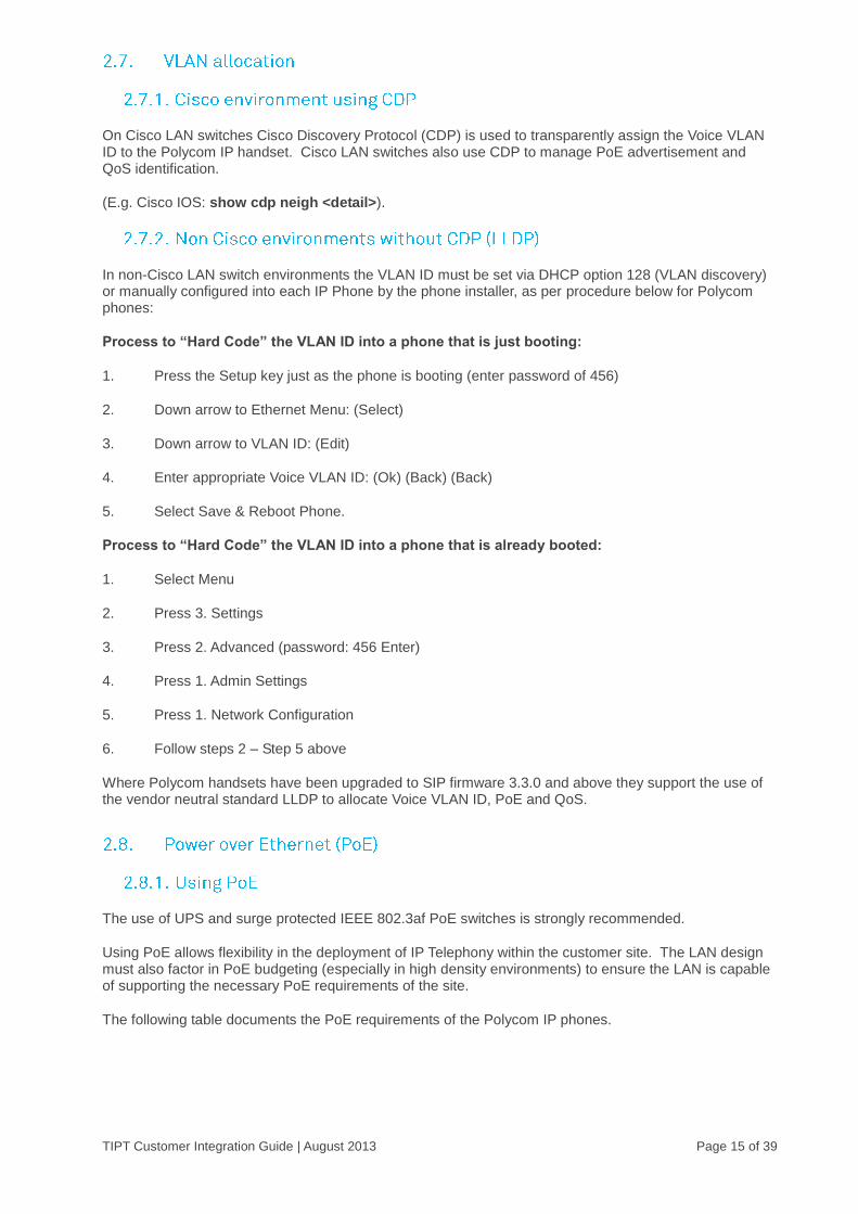
On Cisco LAN switches Cisco Discovery Protocol (CDP) is used to transparently assign the Voice VLAN ID to the Polycom IP handset. Cisco LAN switches also use CDP to manage PoE advertisement and QoS identification.
(E.g. Cisco IOS: show cdp neigh <detail>).
In non-Cisco LAN switch environments the VLAN ID must be set via DHCP option 128 (VLAN discovery) or manually configured into each IP Phone by the phone installer, as per procedure below for Polycom phones:
Process to “Hard Code” the VLAN ID into a phone that is just booting:
1. Press the Setup key just as the phone is booting (enter password of 456)
2. Down arrow to Ethernet Menu: (Select)
3. Down arrow to VLAN ID: (Edit)
4. Enter appropriate Voice VLAN ID: (Ok) (Back) (Back)
5. Select Save & Reboot Phone.
Process to “Hard Code” the VLAN ID into a phone that is already booted:
1. Select Menu
2. Press 3. Settings
3. Press 2. Advanced (password: 456 Enter)
4. Press 1. Admin Settings
5. Press 1. Network Configuration
6. Follow steps 2 – Step 5 above
Where Polycom handsets have been upgraded to SIP firmware 3.3.0 and above they support the use of the vendor neutral standard LLDP to allocate Voice VLAN ID, PoE and QoS.
The use of UPS and surge protected IEEE 802.3af PoE switches is strongly recommended.
Using PoE allows flexibility in the deployment of IP Telephony within the customer site. The LAN design must also factor in PoE budgeting (especially in high density environments) to ensure the LAN is capable of supporting the necessary PoE requirements of the site.
The following table documents the PoE requirements of the Polycom IP phones.
TIPT Customer Integration Guide | August 2013 Page 16 of 39
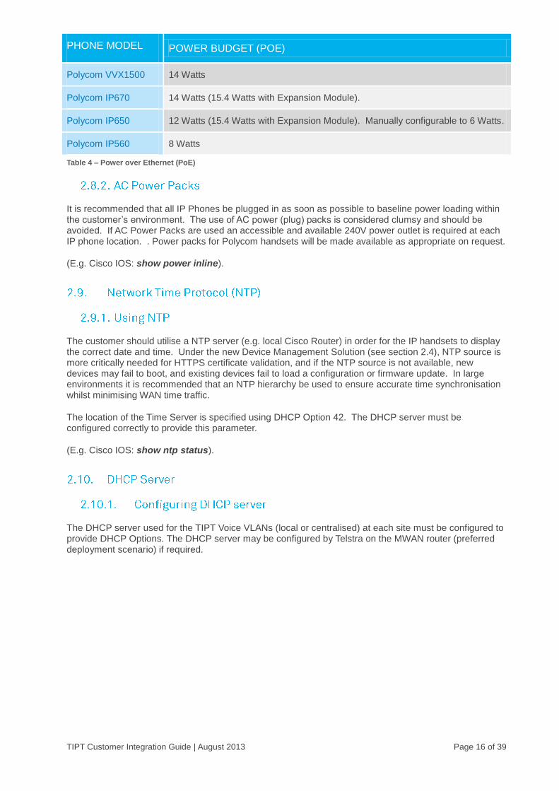
PHONE MODEL POWER BUDGET (POE)
Polycom VVX1500 14 Watts
Polycom IP670 14 Watts (15.4 Watts with Expansion Module).
Polycom IP650 12 Watts (15.4 Watts with Expansion Module). Manually configurable to 6 Watts.
Polycom IP560 8 Watts
Table 4 – Power over Ethernet (PoE)
It is recommended that all IP Phones be plugged in as soon as possible to baseline power loading within the customer’s environment. The use of AC power (plug) packs is considered clumsy and should be avoided. If AC Power Packs are used an accessible and available 240V power outlet is required at each IP phone location. . Power packs for Polycom handsets will be made available as appropriate on request.
(E.g. Cisco IOS: show power inline).
The customer should utilise a NTP server (e.g. local Cisco Router) in order for the IP handsets to display the correct date and time. Under the new Device Management Solution (see section 2.4), NTP source is more critically needed for HTTPS certificate validation, and if the NTP source is not available, new devices may fail to boot, and existing devices fail to load a configuration or firmware update. In large environments it is recommended that an NTP hierarchy be used to ensure accurate time synchronisation whilst minimising WAN time traffic.
The location of the Time Server is specified using DHCP Option 42. The DHCP server must be configured correctly to provide this parameter.
(E.g. Cisco IOS: show ntp status).
The DHCP server used for the TIPT Voice VLANs (local or centralised) at each site must be configured to provide DHCP Options. The DHCP server may be configured by Telstra on the MWAN router (preferred deployment scenario) if required.
TIPT Customer Integration Guide | August 2013 Page 17 of 39
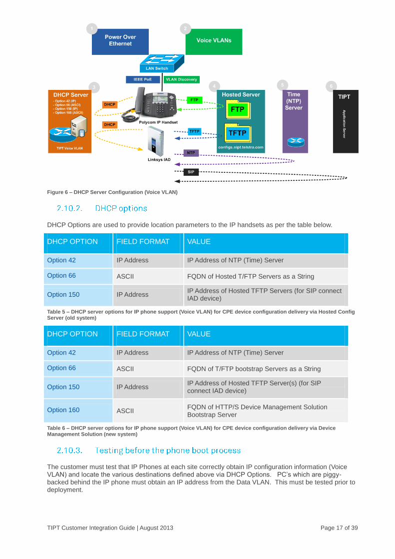
Figure 6 – DHCP Server Configuration (Voice VLAN)
DHCP Options are used to provide location parameters to the IP handsets as per the table below.
DHCP OPTION FIELD FORMAT VALUE
Option 42 IP Address IP Address of NTP (Time) Server
Option 66 ASCII FQDN of Hosted T/FTP Servers as a String
Option 150 IP Address IP Address of Hosted TFTP Servers (for SIP connect IAD device)
Table 5 – DHCP server options for IP phone support (Voice VLAN) for CPE device configuration delivery via Hosted Config Server (old system)
DHCP OPTION FIELD FORMAT VALUE
Option 42 IP Address IP Address of NTP (Time) Server
Option 66 ASCII FQDN of T/FTP bootstrap Servers as a String
Option 150 IP Address IP Address of Hosted TFTP Server(s) (for SIP connect IAD device)
Option 160 ASCII FQDN of HTTP/S Device Management Solution Bootstrap Server
Table 6 – DHCP server options for IP phone support (Voice VLAN) for CPE device configuration delivery via Device Management Solution (new system)
The customer must test that IP Phones at each site correctly obtain IP configuration information (Voice VLAN) and locate the various destinations defined above via DHCP Options. PC’s which are piggy-backed behind the IP phone must obtain an IP address from the Data VLAN. This must be tested prior to deployment.
TIPT Customer Integration Guide | August 2013 Page 18 of 39
Messages pertaining to “Unable to obtain DHCP” or “Unable to locate Boot Server” must not be presented during the phone boot process. If you get one of these messages it indicates a DHCP configuration issue.
The following Cisco IOS DHCP Server (Voice VLAN) configuration template may be used. Please note requirement for Telstra TIPT DNS to be used in the customer Voice VLAN scope.
CISCO IOS DHCP SERVER CONFIGURATION
service dhcp server
ip dhcp excluded-address 192.168.100.1 192.168.100.10
ip dhcp pool TIPT_VoiceVLAN
network 192.168.100.0 255.255.255.0
default-router 192.168.100.1
dns-server 203.52.0.221 203.52.1.222
lease 7
option 42 ip 192.168.100.1
Hosted Configuration Server Device Management Solution
option 66 ascii "configs.nipt.telstra.com"
option 150 ip 203.52.0.206 203.52.1.206
option 66 ascii "dms.digitalbusiness.telstra.com"
option 150 ip 203.52.0.206 203.52.1.206
option 160 ascii "http://polydms.digitalbusiness.telstra.com/dms/bootstrap"
Table 7 – Cisco IOS DHCP Server Template (Voice VLANs)
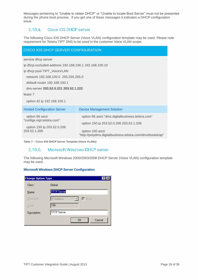
The following Microsoft Windows 2000/2003/2008 DHCP Server (Voice VLAN) configuration template may be used.
Microsoft Windows DHCP Server Configuration

TIPT Customer Integration Guide | August 2013 Page 19 of 39
Microsoft Windows DHCP Server Template (Voice VLANs) - Hosted Configuration Server
Notes: DHCP Option 150 (IP Address - Array) must be added via “Set Predefined Options”.
Ensure the DHCP Option Data Type is set correctly.
Microsoft Windows DHCP Server Configuration
Microsoft Windows DHCP Server Template (Voice VLANs) – Device Management Solution
Notes: DHCP Option 150 (IP Address - Array) must be added via “Set Predefined Options”.
Ensure the DHCP Option Data Type is set correctly.

TIPT Customer Integration Guide | August 2013 Page 20 of 39
If the customer has a premise based DNS server(s) it must be configured for DNS conditional forwarding for the “nipt.telstra.com” and “tipt.telstra.com” domains as per the table below.
This is required to utilise the TIPT applications including; Toolbar, miRECEPTION and CommPilot web. DNS conditional forwarding is supported by Windows 2003 but not Windows 2000 Server.
PARAMETER CONFIGURATION
Forwarder – DNS Domain Name
nipt.telstra.com
tipt.telstra.com
Primary Domain Forwarder 203.52.0.221
Secondary Domain Forwarder 203.52.1.222
Table 11 – Conditional DNS forwarding
If the customer cannot integrate its on-site DNS (e.g. Windows DNS 2000) then the integration is performed via existing Internet DNS referrals. If the customer selects this sub-optimal architecture then TIPT applications may be impacted by an Internet outage. IP Phones within the Voice VLAN are not affected.
Figure 7 – DNS Server Configuration (Conditional DNS Forwarding)
TIPT Customer Integration Guide | August 2013 Page 21 of 39
The “nslookup” tool must be used from both the customers DNS server(s) and an on-site PC client to verify name resolution to the TIPT hosts as per below. The nslookup should also be performed on the Voice VLAN to ensure name resolution from the IP phone.
NAME RESOLUTION VALIDATION WEB HOSTS
> nslookup ews.tipt.telstra.com
Addresses : 144.140.208.81, 144.140.181.80
> nslookup sbc-vic.nipt.telstra.com
Address: 203.52.0.167
Additionally customers must also be able to access the following hosts:
https://ews.tipt.telstra.com
Note: Access to these sites will only be available once interconnects are established.
Table 12 – DNS Name Resolution Validation (“nslookup”)
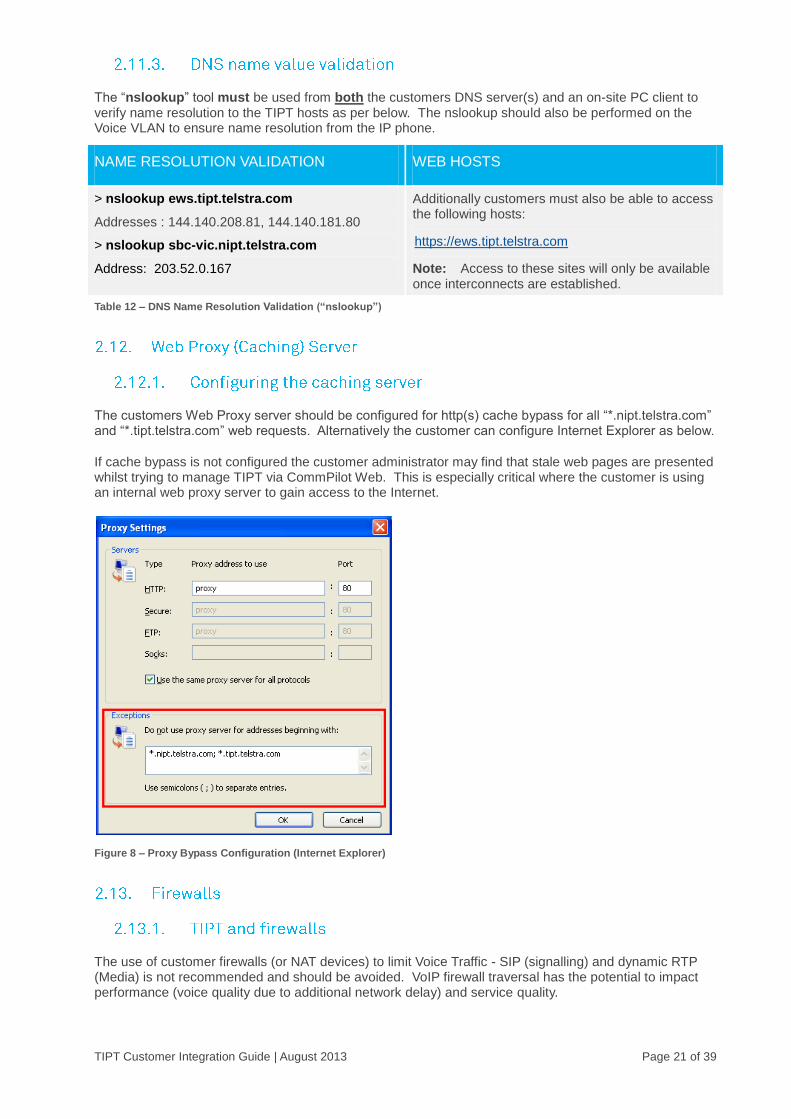
The customers Web Proxy server should be configured for http(s) cache bypass for all “*.nipt.telstra.com” and “*.tipt.telstra.com” web requests. Alternatively the customer can configure Internet Explorer as below.
If cache bypass is not configured the customer administrator may find that stale web pages are presented whilst trying to manage TIPT via CommPilot Web. This is especially critical where the customer is using an internal web proxy server to gain access to the Internet.
Figure 8 – Proxy Bypass Configuration (Internet Explorer)
The use of customer firewalls (or NAT devices) to limit Voice Traffic - SIP (signalling) and dynamic RTP (Media) is not recommended and should be avoided. VoIP firewall traversal has the potential to impact performance (voice quality due to additional network delay) and service quality.
TIPT Customer Integration Guide | August 2013 Page 22 of 39
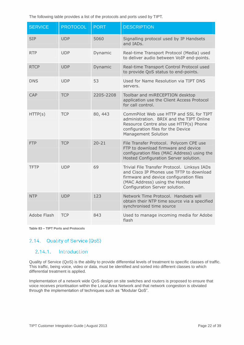
The following table provides a list of the protocols and ports used by TIPT.
SERVICE PROTOCOL PORT DESCRIPTION
SIP UDP 5060 Signalling protocol used by IP Handsets
and IADs.
RTP UDP Dynamic Real-time Transport Protocol (Media) used
to deliver audio between VoIP end-points.
RTCP UDP Dynamic Real-time Transport Control Protocol used
to provide QoS status to end-points.
DNS UDP 53 Used for Name Resolution via TIPT DNS
servers.
CAP TCP 2205-2208 Toolbar and miRECEPTION desktop
application use the Client Access Protocol
for call control.
HTTP(s) TCP 80, 443 CommPilot Web use HTTP and SSL for TIPT
administration. BRIX and the TIPT Online
Resource Centre also use HTTP(s) Phone
configuration files for the Device
Management Solution
FTP TCP 20-21 File Transfer Protocol. Polycom CPE use
FTP to download firmware and device
configuration files (MAC Address) using the
Hosted Configuration Server solution.
TFTP UDP 69 Trivial File Transfer Protocol. Linksys IADs
and Cisco IP Phones use TFTP to download
firmware and device configuration files
(MAC Address) using the Hosted
Configuration Server solution.
NTP UDP 123 Network Time Protocol. Handsets will
obtain their NTP time source via a specified
synchronised time source
Adobe Flash TCP 843 Used to manage incoming media for Adobe
flash
Table 83 – TIPT Ports and Protocols
Quality of Service (QoS) is the ability to provide differential levels of treatment to specific classes of traffic. This traffic, being voice, video or data, must be identified and sorted into different classes to which differential treatment is applied.
Implementation of a network wide QoS design on site switches and routers is proposed to ensure that voice receives prioritisation within the Local Area Network and that network congestion is obviated through the implementation of techniques such as “Modular QoS”.
TIPT Customer Integration Guide | August 2013 Page 23 of 39
Implementation of Telstra’s IP MAN/IP WAN Dynamic CoS will ensure that voice receives prioritisation within the Wide Area Network and that network congestion is obviated through the implementation of techniques such as “Egress Queuing”.
A Quality of Service Policy will address the key issues of:
Classification and Marking
Congestion Management
Congestion Avoidance
Traffic Policing and Shaping, and
Link Efficiency.
In order to provide an enterprise grade of service for TIPT is required that the customer’s network support end-to-end QoS. The WAN edge router must be configured to categorise and prioritise TIPT traffic accordingly.
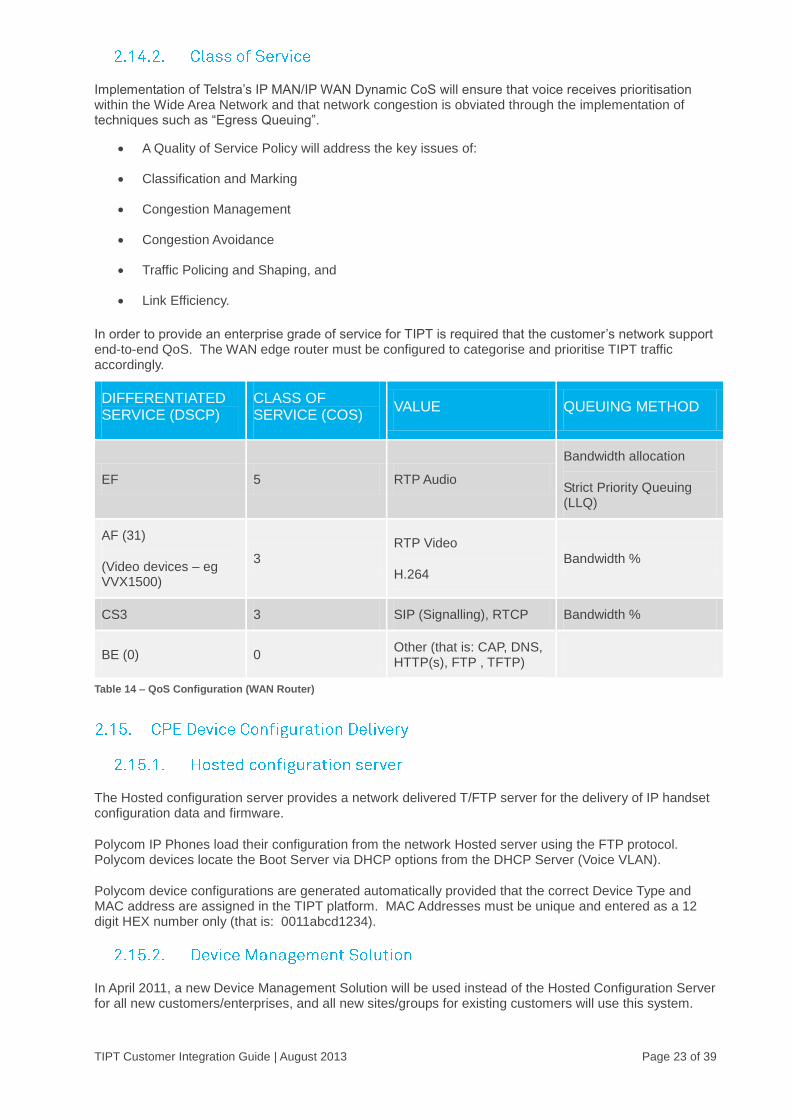
DIFFERENTIATED SERVICE (DSCP)
CLASS OF SERVICE (COS)
VALUE QUEUING METHOD
EF 5 RTP Audio
Bandwidth allocation
Strict Priority Queuing (LLQ)
AF (31)
(Video devices – eg VVX1500)
3
RTP Video
H.264
Bandwidth %
CS3 3 SIP (Signalling), RTCP Bandwidth %
BE (0) 0 Other (that is: CAP, DNS, HTTP(s), FTP , TFTP)
Table 14 – QoS Configuration (WAN Router)
The Hosted configuration server provides a network delivered T/FTP server for the delivery of IP handset configuration data and firmware.
Polycom IP Phones load their configuration from the network Hosted server using the FTP protocol. Polycom devices locate the Boot Server via DHCP options from the DHCP Server (Voice VLAN).
Polycom device configurations are generated automatically provided that the correct Device Type and MAC address are assigned in the TIPT platform. MAC Addresses must be unique and entered as a 12 digit HEX number only (that is: 0011abcd1234).
In April 2011, a new Device Management Solution will be used instead of the Hosted Configuration Server for all new customers/enterprises, and all new sites/groups for existing customers will use this system.

TIPT Customer Integration Guide | August 2013 Page 24 of 39
The DHCP options and protocols used are different than the previous Hosted Configuration Server solution (as detailed in section 2.2.6). This solution is “internet ready”, with the use of HTTPS for security. The Device Management Solution will also deliver enhanced firmware management capability and new user features.
The other key change brought about by DMS, is that provisioning/activation of devices is based on user name and password, rather than MAC address. This provides more flexibility for provisioning, upgrading and replacing phones. You will be advised of your Username and Password from your Customer Group Administrator. The username will be your phone number.
If you are required to initially configure a brand new Polycom IP phone you will see a QSetup soft key on the screen on your phone. Pressing the QSetup soft key takes the user directly to the menu where the supplied username and password for that device needs to be entered. Once the username and password have been entered the user will be prompted to save the new configuration.
If a phone has already been previously configured (with user name and password) via Qsetup, the QSetup soft key will not be displayed on the screen when the phone is powered up – eg after the phone has been unplugged or otherwise experienced a power supply interuption.
At the introduction of DMS, all existing Polycom phones are supported (ie 30X / 430 / 50X / 550 / 560 / 60X / 650 / 670 / VVX1500 / 4000 / 6000 / 7000), although older phones models IP301, IP430, IP501, IP600, IP601 and IP4000 do not support the QSetup soft key. The IP300 and IP500 Polycoms are NOT supported by the DMS solution and will be swapped out as part of the DMS migration process. Detailed step by step instructions for each phone model can be found at :
http://www.telstraenterprise.com/support/tiptresources/Pages/PhoneUsers.aspx
Using the CommPilot web portal a suitably trained customer administrator can perform their own Add Moves and Changes (AMCs). Alternatively this function can be performed by the Telstra Managed Voice Service (MVS) Help Desk.
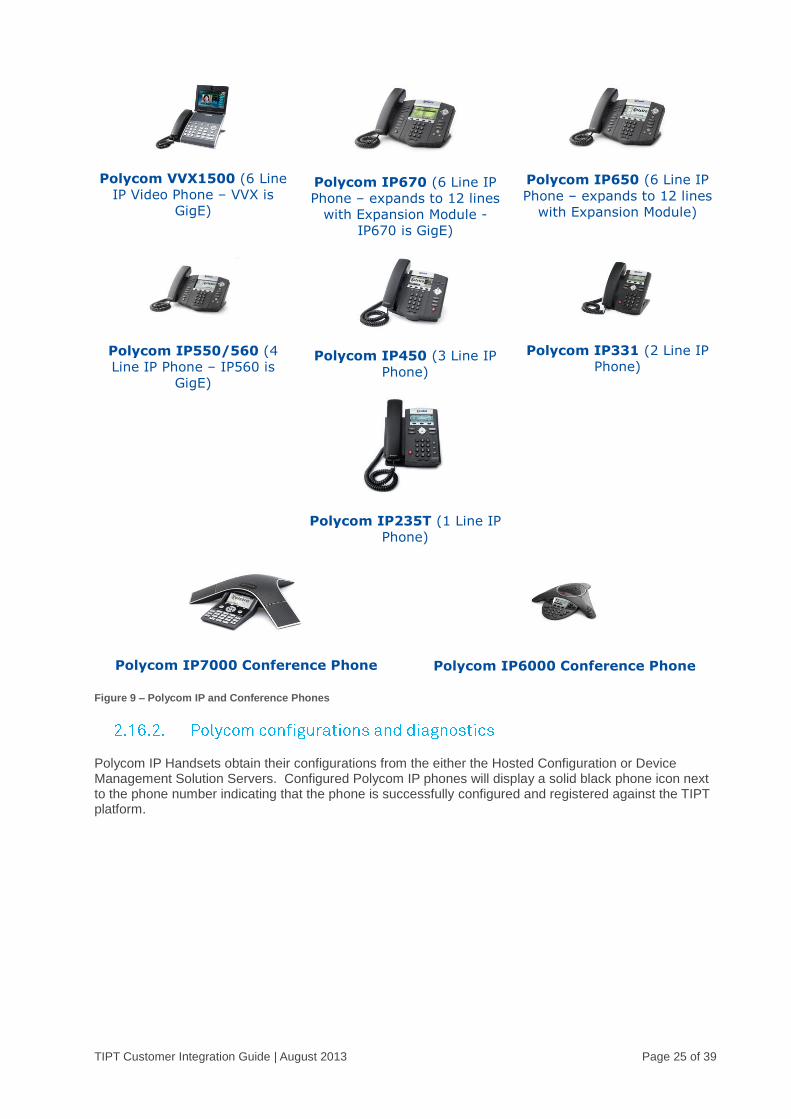
There are seven models of TIPT IP phones and two IP conference phone that can be deployed. The Polycom IP550 phone is the recommended standard office telephony phone type.
TIPT Customer Integration Guide | August 2013 Page 25 of 39
Polycom VVX1500 (6 Line
IP Video Phone – VVX is
GigE)
Polycom IP670 (6 Line IP
Phone – expands to 12 lines
with Expansion Module -
IP670 is GigE)
Polycom IP650 (6 Line IP
Phone – expands to 12 lines
with Expansion Module)
Polycom IP550/560 (4
Line IP Phone – IP560 is
GigE)
Polycom IP450 (3 Line IP
Phone)
Polycom IP235T (1 Line IP
Phone)
Polycom IP331 (2 Line IP
Phone)
Polycom IP7000 Conference Phone
Polycom IP6000 Conference Phone
Figure 9 – Polycom IP and Conference Phones
Polycom IP Handsets obtain their configurations from the either the Hosted Configuration or Device Management Solution Servers. Configured Polycom IP phones will display a solid black phone icon next to the phone number indicating that the phone is successfully configured and registered against the TIPT platform.

TIPT Customer Integration Guide | August 2013 Page 26 of 39
The Polycom IP phone has a diagnostic menu that can be used to verify the phones’ audio quality and keypad functions
Figure 10 – Polycom IP Phone Display (Registered Phone)
The VLANID is set as per section 2.7 VLAN Allocation
The Linksys SPA2102 and SPA8000 IADs obtain their configuration from the Hosted Configuration or Device Management Solution servers. Configured IADs will present dial tone via an analogue handset.
The LAN Switch port to which the IAD is connected must be programmed in the Voice VLAN (e.g. VLAN 100). Also, the SPA2102 must be connected to the LAN switch using the “Internet” port (Blue colour port) and not the port marked Ethernet.
NOTE: If the IAD is connected with the wrong port, this will stop IP phones from working as the IAD will act as a DHCP server providing IP subnet network addresses from the 192.168.0.0/24 range.
Linksys SPA8000 Linksys SPA2102
Figure 11 – Linksys IADs

TIPT Customer Integration Guide | August 2013 Page 27 of 39
The Desktop device that will be running UC-One will need to have the following URL’s resolvable and connectivity to
XSP:
https://cmanager.tipt.telstra.com/uc-one/pc
https://xsi-actions.tipt.telstra.com
SBC
The SBC that the customers CPE points to.
The mobile device that will be running UC-One will need to have the following URL’s resolvable and connectivity to as above except they will also need this additional address resolvable:
https://cmanager.tipt.telstra.com/uc-one/mobile
SBC
The SBC that the customers CPE points to.
This will need to be checked via the customers APN, Office Wi-Fi or VPN if the customer wishes to deploy such a solution.
SERVICE PORT
Signalling 5060
RTP for Voice 16384 - 32767
RTP for Video 8600 - 86968
It must be noted that there is No Guarantee of Voice Quality on calls via UC-One, however Implementation of QOS at a site may assist to mitigate network performance issues that may be experienced with voice/video quality.
TIPT Customer Integration Guide | August 2013 Page 28 of 39
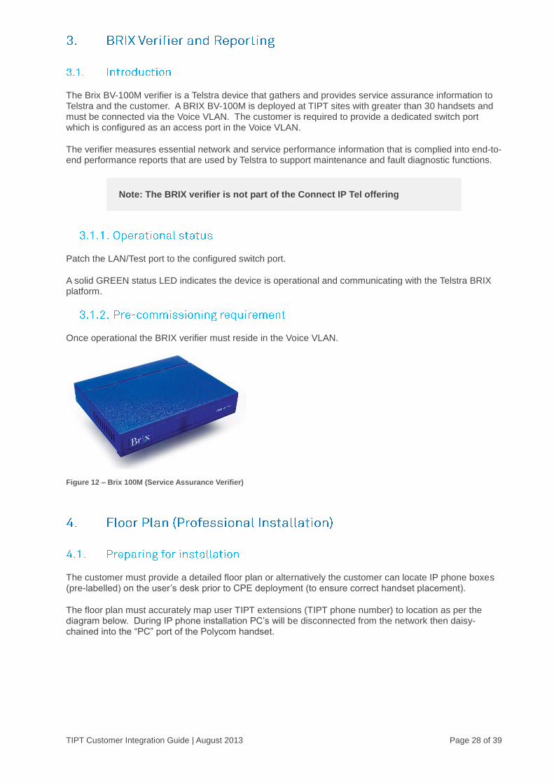
The Brix BV-100M verifier is a Telstra device that gathers and provides service assurance information to Telstra and the customer. A BRIX BV-100M is deployed at TIPT sites with greater than 30 handsets and must be connected via the Voice VLAN. The customer is required to provide a dedicated switch port which is configured as an access port in the Voice VLAN.
The verifier measures essential network and service performance information that is complied into end-to-end performance reports that are used by Telstra to support maintenance and fault diagnostic functions.
Note: The BRIX verifier is not part of the Connect IP Tel offering
Patch the LAN/Test port to the configured switch port.
A solid GREEN status LED indicates the device is operational and communicating with the Telstra BRIX platform.
Once operational the BRIX verifier must reside in the Voice VLAN.
Figure 12 – Brix 100M (Service Assurance Verifier)
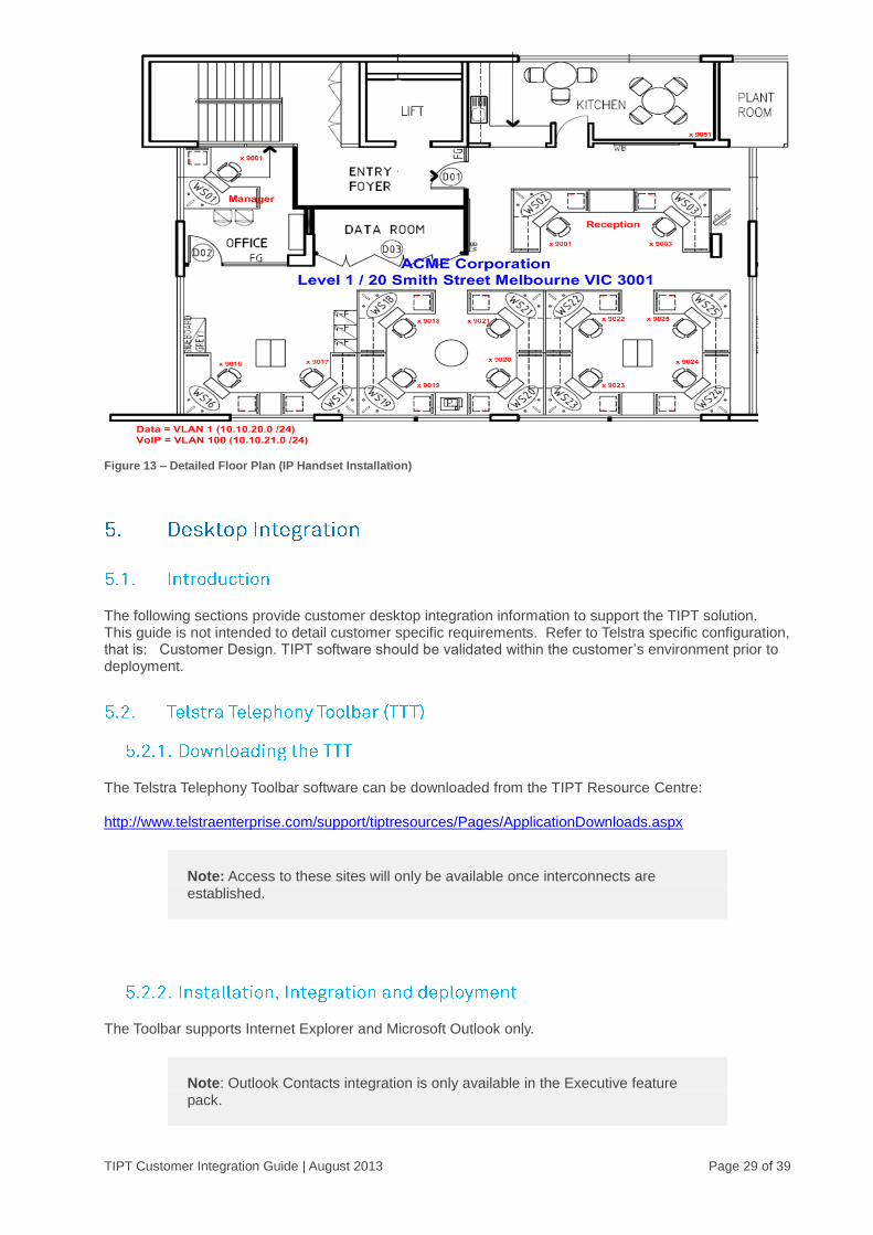
The customer must provide a detailed floor plan or alternatively the customer can locate IP phone boxes (pre-labelled) on the user’s desk prior to CPE deployment (to ensure correct handset placement).
The floor plan must accurately map user TIPT extensions (TIPT phone number) to location as per the diagram below. During IP phone installation PC’s will be disconnected from the network then daisy-chained into the “PC” port of the Polycom handset.
TIPT Customer Integration Guide | August 2013 Page 29 of 39
Figure 13 – Detailed Floor Plan (IP Handset Installation)
The following sections provide customer desktop integration information to support the TIPT solution. This guide is not intended to detail customer specific requirements. Refer to Telstra specific configuration, that is: Customer Design. TIPT software should be validated within the customer’s environment prior to deployment.
The Telstra Telephony Toolbar software can be downloaded from the TIPT Resource Centre:
http://www.telstraenterprise.com/support/tiptresources/Pages/ApplicationDownloads.aspx
Note: Access to these sites will only be available once interconnects are
established.
The Toolbar supports Internet Explorer and Microsoft Outlook only.
Note: Outlook Contacts integration is only available in the Executive feature pack.

TIPT Customer Integration Guide | August 2013 Page 30 of 39
Toolbar requires desktop administrative access to install. All user applications must be closed before installation of the toolbar application. The toolbar must be installed and configured prior to training.
Desktop deployment (including interoperability testing) and configuration of the Toolbar is the responsibility of the customer. Toolbar configuration requires both the case-sensitive username, for example: [email protected] and password to be specified.
Refer to Toolbar installation and configuration instructions at:
http://www.telstraenterprise.com/support/tiptresources/Pages/PhoneUsers.aspx
The following Quick Reference guide describes the features of the Telstra Telephony Toolbar. Full details are available from:
http://www.telstraenterprise.com/support/tiptresources/Pages/PhoneUsers.aspx
Note: Access to these sites will only be available once interconnects are established.
Existing Web directories can be easily enhanced to support Toolbar click to call and click to blind transfer using the following HTML Toolbar tags as per the sample below.
To dial a number use the following as a Hyperlink “TT:<PhoneNumber>?Dial”
To perform a blind transfer whilst on a call use the following as a Hyperlink
“TT:<PhoneNumber>? BlndTransfer”
TIPT Customer Integration Guide | August 2013 Page 31 of 39
SERVICE NUMBER DIAL BLIND TRANSFER
Telstra Time Service 1194
Telstra Weather Service 1196
TAXI 131 008
Table 17 – Toolbar Smart Tags (Sample)
Figure 14 – Toolbar Smart Tags
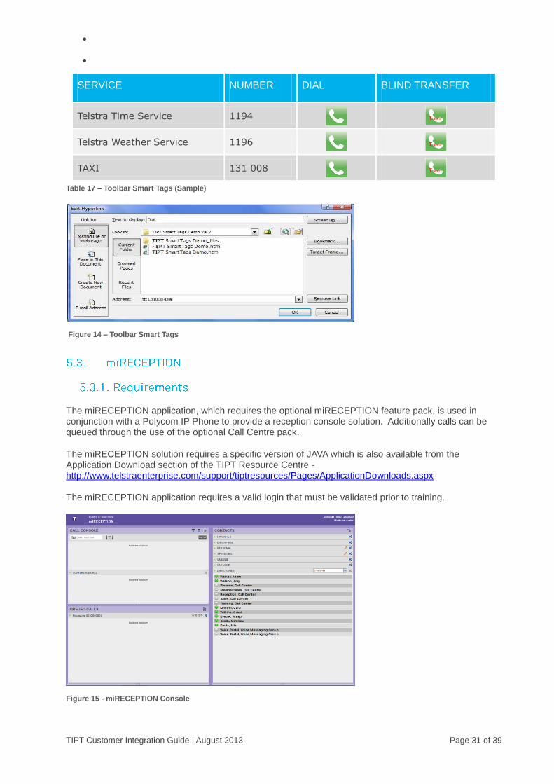
The miRECEPTION application, which requires the optional miRECEPTION feature pack, is used in conjunction with a Polycom IP Phone to provide a reception console solution. Additionally calls can be queued through the use of the optional Call Centre pack.
The miRECEPTION solution requires a specific version of JAVA which is also available from the Application Download section of the TIPT Resource Centre - http://www.telstraenterprise.com/support/tiptresources/Pages/ApplicationDownloads.aspx
The miRECEPTION application requires a valid login that must be validated prior to training.
Figure 15 - miRECEPTION Console
TIPT Customer Integration Guide | August 2013 Page 32 of 39
Refer to the links below for installation & configuration instructions;
http://www.telstraenterprise.com/support/tiptresources/Pages/Receptionist.aspx
Note: Access to these sites will only be available once interconnects are
established.
The following sections provide the customer with additional information in relation is miscellaneous integration components.
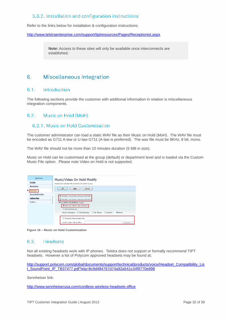
The customer administrator can load a static WAV file as their Music on Hold (MoH). The WAV file must be encoded as G711 A-law or U-law G711 (A-law is preferred). The wav file must be 8KHz, 8 bit, mono.
The WAV file should not be more than 10 minutes duration (5 MB in size).
Music on Hold can be customised at the group (default) or department level and is loaded via the Custom Music File option. Please note Video on Hold is not supported.
Figure 16 – Music on Hold Customisation
Not all existing headsets work with IP phones. Telstra does not support or formally recommend TIPT headsets. However a list of Polycom approved headsets may be found at;
http://support.polycom.com/global/documents/support/technical/products/voice/Headset_Compatibility_List_SoundPoint_IP_TB37477.pdf?elq=8c9d484767d74a92a541c34f9770e898
Sennheiser link:
http://www.sennheiserusa.com/cordless-wireless-headsets-office
TIPT Customer Integration Guide | August 2013 Page 33 of 39
Jabra link:
http://www.jabra.com/au-cp/unified-communications/pages/discoverproducts.aspx
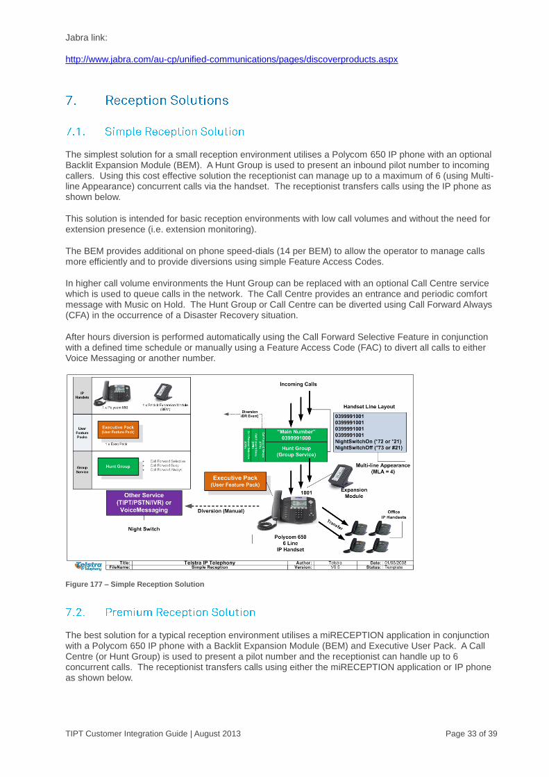
The simplest solution for a small reception environment utilises a Polycom 650 IP phone with an optional Backlit Expansion Module (BEM). A Hunt Group is used to present an inbound pilot number to incoming callers. Using this cost effective solution the receptionist can manage up to a maximum of 6 (using Multi-line Appearance) concurrent calls via the handset. The receptionist transfers calls using the IP phone as shown below.
This solution is intended for basic reception environments with low call volumes and without the need for extension presence (i.e. extension monitoring).
The BEM provides additional on phone speed-dials (14 per BEM) to allow the operator to manage calls more efficiently and to provide diversions using simple Feature Access Codes.
In higher call volume environments the Hunt Group can be replaced with an optional Call Centre service which is used to queue calls in the network. The Call Centre provides an entrance and periodic comfort message with Music on Hold. The Hunt Group or Call Centre can be diverted using Call Forward Always (CFA) in the occurrence of a Disaster Recovery situation.
After hours diversion is performed automatically using the Call Forward Selective Feature in conjunction with a defined time schedule or manually using a Feature Access Code (FAC) to divert all calls to either Voice Messaging or another number.
Figure 177 – Simple Reception Solution
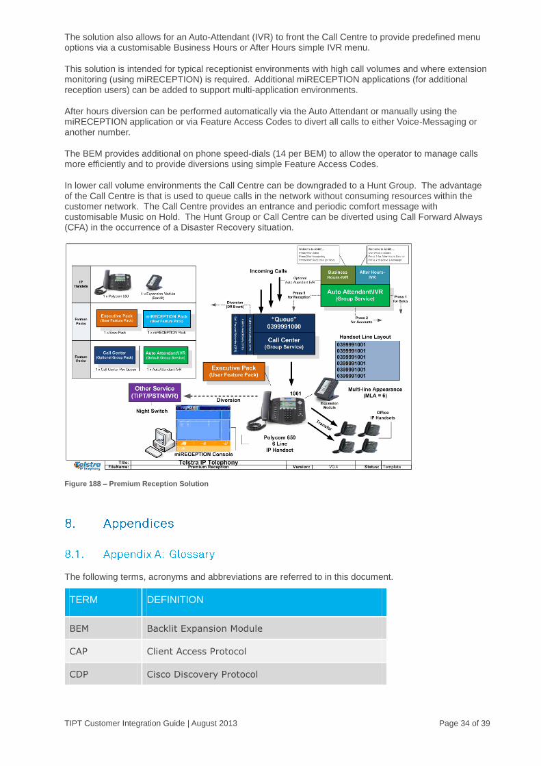
The best solution for a typical reception environment utilises a miRECEPTION application in conjunction with a Polycom 650 IP phone with a Backlit Expansion Module (BEM) and Executive User Pack. A Call Centre (or Hunt Group) is used to present a pilot number and the receptionist can handle up to 6 concurrent calls. The receptionist transfers calls using either the miRECEPTION application or IP phone as shown below.
TIPT Customer Integration Guide | August 2013 Page 34 of 39
The solution also allows for an Auto-Attendant (IVR) to front the Call Centre to provide predefined menu options via a customisable Business Hours or After Hours simple IVR menu.
This solution is intended for typical receptionist environments with high call volumes and where extension monitoring (using miRECEPTION) is required. Additional miRECEPTION applications (for additional reception users) can be added to support multi-application environments.
After hours diversion can be performed automatically via the Auto Attendant or manually using the miRECEPTION application or via Feature Access Codes to divert all calls to either Voice-Messaging or another number.
The BEM provides additional on phone speed-dials (14 per BEM) to allow the operator to manage calls more efficiently and to provide diversions using simple Feature Access Codes.
In lower call volume environments the Call Centre can be downgraded to a Hunt Group. The advantage of the Call Centre is that is used to queue calls in the network without consuming resources within the customer network. The Call Centre provides an entrance and periodic comfort message with customisable Music on Hold. The Hunt Group or Call Centre can be diverted using Call Forward Always (CFA) in the occurrence of a Disaster Recovery situation.
Figure 188 – Premium Reception Solution
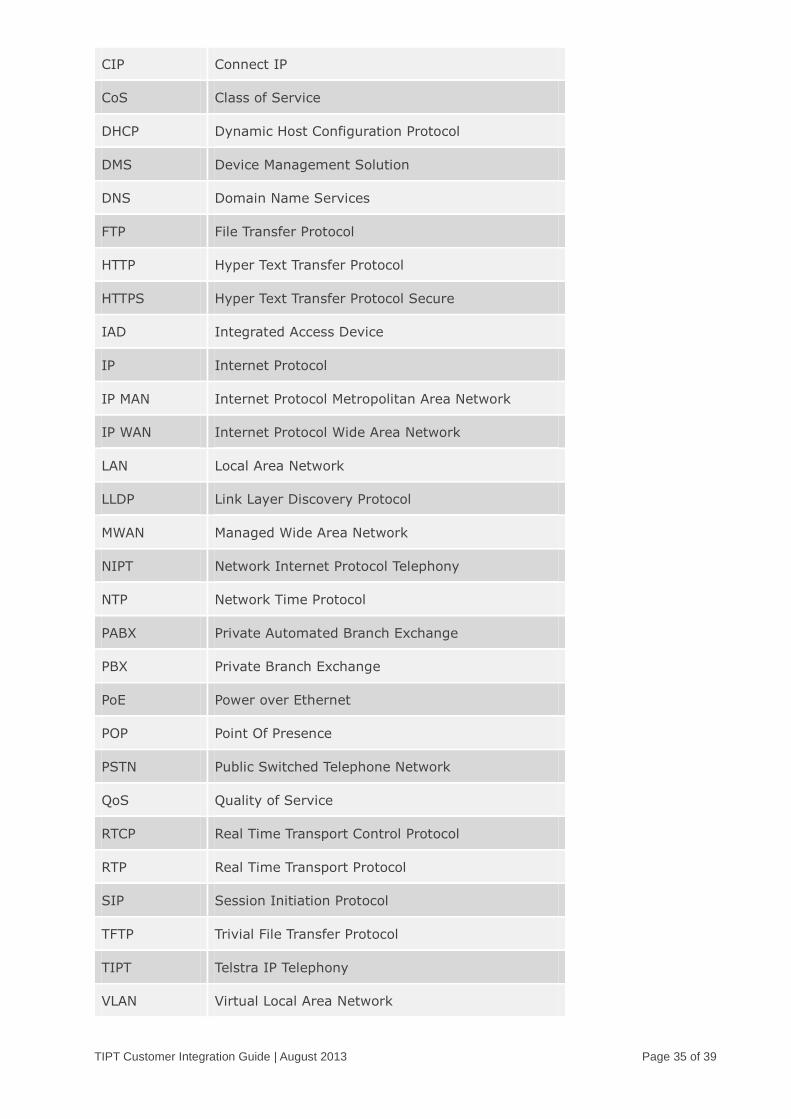
The following terms, acronyms and abbreviations are referred to in this document.
TERM DEFINITION
BEM Backlit Expansion Module
CAP Client Access Protocol
CDP Cisco Discovery Protocol
TIPT Customer Integration Guide | August 2013 Page 35 of 39
CIP Connect IP
CoS Class of Service
DHCP Dynamic Host Configuration Protocol
DMS Device Management Solution
DNS Domain Name Services
FTP File Transfer Protocol
HTTP Hyper Text Transfer Protocol
HTTPS Hyper Text Transfer Protocol Secure
IAD Integrated Access Device
IP Internet Protocol
IP MAN Internet Protocol Metropolitan Area Network
IP WAN Internet Protocol Wide Area Network
LAN Local Area Network
LLDP Link Layer Discovery Protocol
MWAN Managed Wide Area Network
NIPT Network Internet Protocol Telephony
NTP Network Time Protocol
PABX Private Automated Branch Exchange
PBX Private Branch Exchange
PoE Power over Ethernet
POP Point Of Presence
PSTN Public Switched Telephone Network
QoS Quality of Service
RTCP Real Time Transport Control Protocol
RTP Real Time Transport Protocol
SIP Session Initiation Protocol
TFTP Trivial File Transfer Protocol
TIPT Telstra IP Telephony
VLAN Virtual Local Area Network
TIPT Customer Integration Guide | August 2013 Page 36 of 39
VoIP Voice over Internet Protocol
VPN Virtual Private Network
WAN Wide Area Network
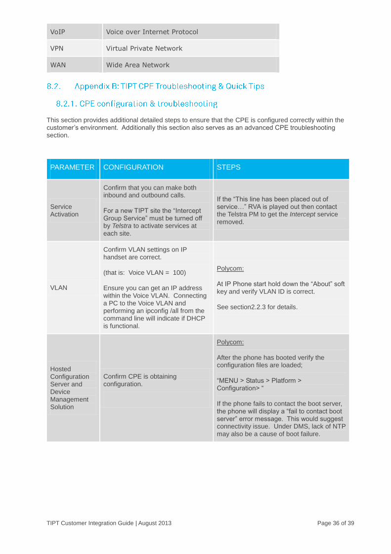
This section provides additional detailed steps to ensure that the CPE is configured correctly within the customer’s environment. Additionally this section also serves as an advanced CPE troubleshooting section.
PARAMETER CONFIGURATION STEPS
Service Activation
Confirm that you can make both inbound and outbound calls.
For a new TIPT site the “Intercept Group Service” must be turned off by Telstra to activate services at each site.
If the “This line has been placed out of service…” RVA is played out then contact the Telstra PM to get the Intercept service removed.
VLAN
Confirm VLAN settings on IP handset are correct.
(that is: Voice VLAN = 100)
Ensure you can get an IP address within the Voice VLAN. Connecting a PC to the Voice VLAN and performing an ipconfig /all from the command line will indicate if DHCP is functional.
Polycom:
At IP Phone start hold down the “About” soft key and verify VLAN ID is correct.
See section2.2.3 for details.
Hosted Configuration Server and Device Management Solution
Confirm CPE is obtaining configuration.
Polycom:
After the phone has booted verify the configuration files are loaded;
“MENU > Status > Platform > Configuration> “
If the phone fails to contact the boot server, the phone will display a “fail to contact boot server” error message. This would suggest connectivity issue. Under DMS, lack of NTP may also be a cause of boot failure.
TIPT Customer Integration Guide | August 2013 Page 37 of 39
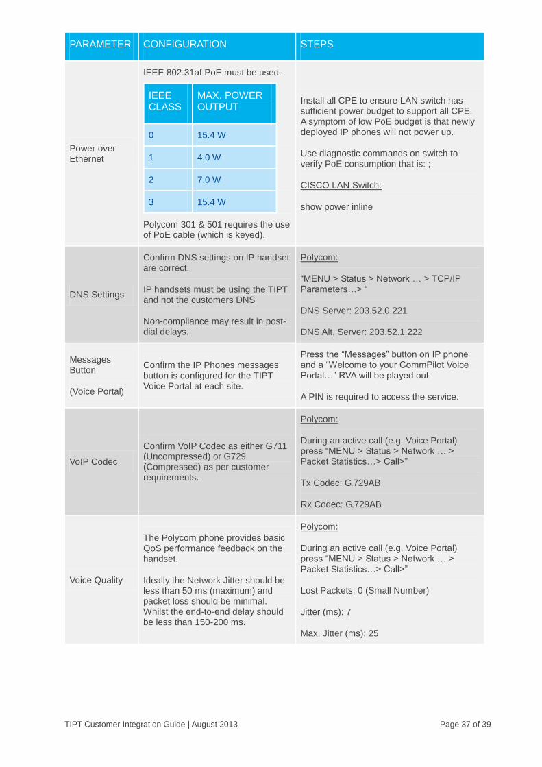
PARAMETER CONFIGURATION STEPS
Power over Ethernet
IEEE 802.31af PoE must be used.
IEEE CLASS
MAX. POWER OUTPUT
0 15.4 W
1 4.0 W
2 7.0 W
3 15.4 W
Polycom 301 & 501 requires the use of PoE cable (which is keyed).
Install all CPE to ensure LAN switch has sufficient power budget to support all CPE. A symptom of low PoE budget is that newly deployed IP phones will not power up.
Use diagnostic commands on switch to verify PoE consumption that is: ;
CISCO LAN Switch:
show power inline
DNS Settings
Confirm DNS settings on IP handset are correct.
IP handsets must be using the TIPT and not the customers DNS
Non-compliance may result in post-dial delays.
Polycom:
“MENU > Status > Network … > TCP/IP Parameters…> “
DNS Server: 203.52.0.221
DNS Alt. Server: 203.52.1.222
Messages Button
(Voice Portal)
Confirm the IP Phones messages button is configured for the TIPT Voice Portal at each site.
Press the “Messages” button on IP phone and a “Welcome to your CommPilot Voice Portal…” RVA will be played out.
A PIN is required to access the service.
VoIP Codec
Confirm VoIP Codec as either G711 (Uncompressed) or G729 (Compressed) as per customer requirements.
Polycom:
During an active call (e.g. Voice Portal) press “MENU > Status > Network … > Packet Statistics…> Call>”
Tx Codec: G.729AB
Rx Codec: G.729AB
Voice Quality
The Polycom phone provides basic QoS performance feedback on the handset.
Ideally the Network Jitter should be less than 50 ms (maximum) and packet loss should be minimal. Whilst the end-to-end delay should be less than 150-200 ms.
Polycom:
During an active call (e.g. Voice Portal) press “MENU > Status > Network … > Packet Statistics…> Call>”
Lost Packets: 0 (Small Number)
Jitter (ms): 7
Max. Jitter (ms): 25

TIPT Customer Integration Guide | August 2013 Page 38 of 39
PARAMETER CONFIGURATION STEPS
MAC Address for IAD’s
The IAD’s obtain their configuration using the MAC address of the device.
Note: If swapping an IAD out, the MAC address will need to be updated in CommPilot by the Customer Administrator.
MAC Address for Phones
For Phone configs delivered over Hosted Config Server MAC address identifies the config for the phone to load.
Polycom: The MAC Address (Serial Number) can be found by pressing “MENU 2-2-2” to obtain the 12 digit HEX MAC address (e.g. 004f201ABCD)
Time
(NTP)
Confirm that the phone is getting correct time from the local simple NTP (Network Time Protocol) server and that the NTP server has the correct time and is synchronised (that is: upstream time server).
The NTP server is provided to the Polycom Handset using DHCP Option 42, confirm that NTP source can actually be reached (there are third party tools available on the web to test if required).
Polycom:
“MENU > Status > Network Settings… > TCP/IP Parameters…> “
SNTP Address: <192.168.100.1>
GMT Offset: <36000(10.0)>
If the phone or NTP server is not synchronised the phone will display a date of “JAN 01”
IADs
Ensure the Integrated Access Device (IAD) is plugged into the Voice VLAN (the switch port will need to be configured as untagged). Ensure the IAD is connected via the Internet port (and not the network port).
The Linksys IADs do not support the piggy-backing of a PC on the network port.
To enter Interactive Voice Response Menu Press ****. Do not press any other keys until you hear, “Linksys configuration menu.
To check the devices IP Address press 110#
Factory Reset
Before returning a faulty IP handset perform a Device Reset to ensure customer details are removed from the handset.
Polycom:
Press and hold “468*” and enter 456 as the password to perform a device reset.
Press and hold “1357” and enter 456 as the password to perform a device reset (Polycom 330).
Press and hold “68*” and enter 456 as the password to perform a device reset (Polycom 4000.
Please ensure that CDP/LLDP is enabled and that the correct VLANID is used. This is required in order for the handset to locate the network.
Table 18 – CPE Testing & Troubleshooting
TIPT Customer Integration Guide | August 2013 Page 39 of 39
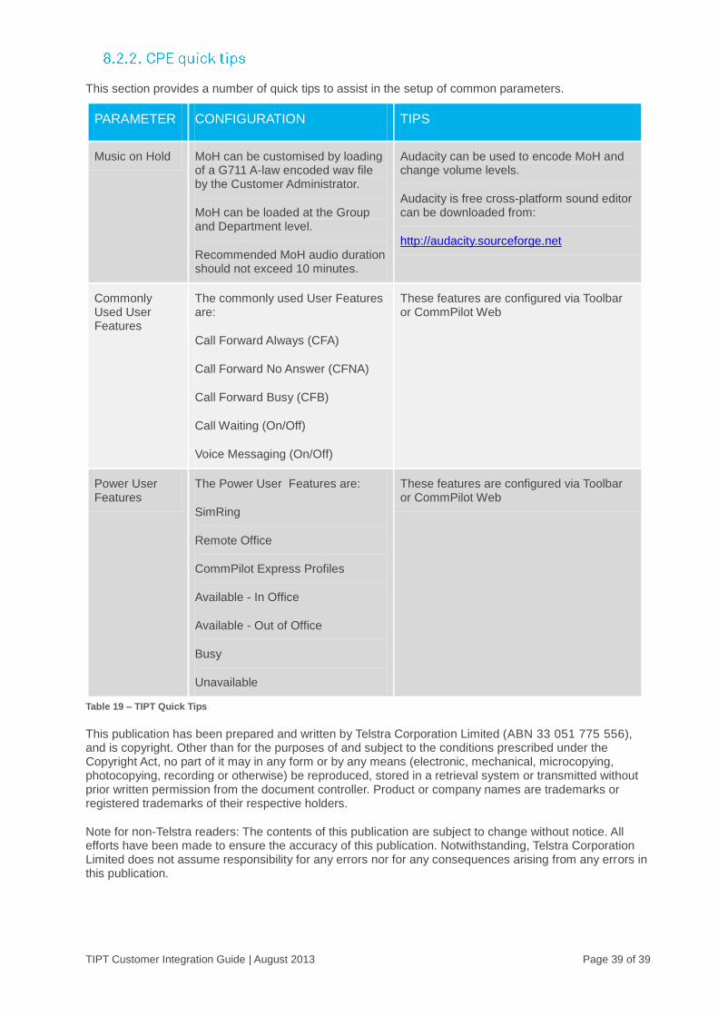
This section provides a number of quick tips to assist in the setup of common parameters.
PARAMETER CONFIGURATION TIPS
Music on Hold MoH can be customised by loading of a G711 A-law encoded wav file by the Customer Administrator.
MoH can be loaded at the Group and Department level.
Recommended MoH audio duration should not exceed 10 minutes.
Audacity can be used to encode MoH and change volume levels.
Audacity is free cross-platform sound editor can be downloaded from:
http://audacity.sourceforge.net
Commonly Used User Features
The commonly used User Features are:
Call Forward Always (CFA)
Call Forward No Answer (CFNA)
Call Forward Busy (CFB)
Call Waiting (On/Off)
Voice Messaging (On/Off)
These features are configured via Toolbar or CommPilot Web
Power User Features
The Power User Features are:
SimRing
Remote Office
CommPilot Express Profiles
Available - In Office
Available - Out of Office
Busy
Unavailable
These features are configured via Toolbar or CommPilot Web
Table 19 – TIPT Quick Tips
This publication has been prepared and written by Telstra Corporation Limited (ABN 33 051 775 556), and is copyright. Other than for the purposes of and subject to the conditions prescribed under the Copyright Act, no part of it may in any form or by any means (electronic, mechanical, microcopying, photocopying, recording or otherwise) be reproduced, stored in a retrieval system or transmitted without prior written permission from the document controller. Product or company names are trademarks or registered trademarks of their respective holders.
Note for non-Telstra readers: The contents of this publication are subject to change without notice. All efforts have been made to ensure the accuracy of this publication. Notwithstanding, Telstra Corporation Limited does not assume responsibility for any errors nor for any consequences arising from any errors in this publication.