Television, HDTV, and Cable TV on Cat 5 or Cat 6 Cable€¦ · Combiner TV TV TV TV TV TV Video...
4
The Lynx ® Television Network Distributes up to 528 digital channels on Cat 5 or Cat 6 cable Excellent for CATV, SMATV, or off-air television distribution Simplifies cabling requirements Increases flexibility for moves, adds and changes Improves reliability Creates a technology bridge to IPTV Television, HDTV, and Cable TV on Cat 5 or Cat 6 Cable simplifies installation, standardizes the wiring, and reduces maintenance requirements. The Lynx Network increases system flexibility because moves, adds, and changes are easy with Cat5/6 cable. A homerun wiring design improves reliability because there are no taps or splitters between the distribution hub and the TV. The Lynx Network also provides a “technology bridge” to IPTV by using the same infrastructure that IPTV will use. A patented RF balun is the centerpiece of the Lynx design. A pair of send / receive baluns delivers a clean RF signal to each TV (on pair four). The baluns use an RF technology that delivers HD, digital, and analog channels on network cables without using any bandwidth on the network itself. The hubs and point of use converters do not require external power, and are bi-directional. External RF amplifiers compensate for cable and insertion losses. The Lynx Television Network simultaneously delivers up to 176 HDTV channels, 528 standard digital channels, or 134 analog channels on Cat 5 or Cat 6 cable. Frequency capabilities are 5 MHz to 860 MHz. A Lynx hub in the wiring closet converts an unbalanced coaxial signal into eight or sixteen balanced signals transmitted on twisted pair cables. At the point of use a wallplate F or single port converter changes the signal back to coaxial form. The Lynx Network simplifies cable requirements by reducing the need for coax. Now television, phone, and data can all be delivered on twisted pair cables. This Wallplate F Single port converter
Transcript of Television, HDTV, and Cable TV on Cat 5 or Cat 6 Cable€¦ · Combiner TV TV TV TV TV TV Video...

The Lynx® Television Network Distributes up to 528 digital
channels on Cat 5 or Cat 6 cable
Excellent for CATV, SMATV, oroff-air television distribution
Simplifies cabling requirements
Increases flexibility for moves, addsand changes
Improves reliability
Creates a technology bridge to IPTV
Television, HDTV, and Cable TVon Cat 5 or Cat 6 Cable
simplifies installation, standardizes the wiring, and reduces maintenance requirements.
The Lynx Network increases system flexibility because moves, adds, and changes are easy with Cat5/6 cable.
A homerun wiring design improves reliability because there are no taps or splitters between the distribution hub and the TV.
The Lynx Network also provides a “technology bridge” to IPTV by using the same infrastructure that IPTV will use.
A patented RF balun is the centerpiece of the Lynx design. A pair of send / receive baluns delivers a clean RF signal to each TV (on pair four). The baluns use an RF technology that delivers HD, digital, and analog channels on network cables without using any bandwidth on the network itself.
The hubs and point of use converters do not require external power, and are bi-directional. External RF amplifiers compensate for cable and insertion losses.
The Lynx Television Network simultaneously delivers up to 176 HDTV channels, 528 standard digital channels, or 134 analog channels on Cat 5 or Cat 6 cable. Frequency capabilities are 5 MHz to 860 MHz.
A Lynx hub in the wiring closet converts an unbalanced coaxial signal into eight or sixteen balanced signals transmitted on twisted pair cables. At the point of use a wallplate F or single port converter changes the signal back to coaxial form.
The Lynx Network simplifies cable requirements by reducing the need for coax. Now television, phone, and data can all be delivered on twisted pair cables. This
Wallplate F Single port converter

CATV
Satellite
Off-Air
DVDs & VCRs
Video Camera
Modulatorsor QAMS
Processors
Modulators
Modulator
Com
bine
r
TV
TV
TV
TV
TV
TV
VideoCamera
HEADEND WIRING CLOSET POINT OF USEHEADEND
Coax Cat 5/6
Amp
Sub-bandModulator3
LC2
LC2
LC2
LC2
LC2
LC2
LC2
Hub
TVLC2
Amp1
Patch
Panel
For use in hospitals, schools, universities, hotels, corporate, MDU, and residential applications.
Applications
Equipment Specifications and Options
1. One amplifier typically supports up to three 8 port hubs (24 TVs). See diagrams on page 3.2. LC is an abbreviation for Lynx converter, which could be a wallplate F converter or a single port converter.3. For use in bi-directional applications. Requires use of a sub-band separator and processor in the headend.
Part Number Width Height Depth Emission Testing
LT hub with rackmount plate
16 port LT hub1 1U 040-01021 19.0" 1.75" 4.5" FCC Part 15 Class A
8 port LT hub1 1U 040-01011 19.0" 1.75" 4.5" FCC Part 15 Class A
LT hub without rackmount (mounts on wall)
8 port LT hub1 040-00901 6.2" 1.4" 4.5" FCC Part 15 Class A
4 port LT hub1 040-02171 3.3" 1.2" 3.7" FCC Part 15 Class A
LC converters
Single port converter 040-0074 .9" .9" 3.3" FCC Part 15 Class A & B
Wallplate F (light almond) 040-0232 Fits in a light almond wallplate ring (PN 809-1663)
Wallplate F (white) 040-0237 Fits in a white wallplate ring (PN 809-1678)
Port terminators2 040-0069 .5" .3" .9" NA
12" coax jumper cable 180-0455 connects the single port converter to the F connector on the TV
Rackmount plates
16 port (two 8s) 809-1274 19.0" 1.75" .1" NA
20 port (five 4s) 809-1647 19.0" 1.75" .1" NA
Amplifier1 35dB gain, 1GHz 180-0465 5.38" 7.63" 3" 20dB slope, 42MHz active return path
1. Amplification is usually needed upstream of each hub. One amplifier usually serves up to 24 drops in each wiring closet. See diagram on next page.2. Port terminators are required for all unused ports in order to prevent electromagnetic emissions. An eight port hub serving six TVs has two unused
ports that must be terminated.U.S. patents 5,495,212 5,633,614 6,150,896
Frequency range 5 MHz to 860 MHzInsertion loss for <13 dB @ 5 MHzhub and converter1 <19 dB @ 860 MHz
Distance capabilities(assumes 41 dB to hub for HD and digital channels and 49 dB to hub for analog channels)
Meters Feet Digital channels(1 MHz)
HD channels(3 MHz)
Analog channels(6 MHz)
90 295 288 96 78
80 260 372 124 99
67 220 528 176 134
1. For a free interactive design model that calculates cable and insertion losses and predicts signal strength at the TV e-mail [email protected].

System Design Suggestions
Residential Packages
One amplifier can usually support up to 24 drops from a given wiring closet, as shown at right below.
Residential packages are available for applications with one to four TVs. These packages are capable of deliv-ering the full range of HD, digital, and analog channels. They include a bi-directional amplifier, Lynx converters, connectors, coax jumpers, and patch cords.
Two types of packages are available. Packages with a 20 dB amp are typically used to deliver “basic” cable TV service with frequencies up to 550MHz. They can also deliver the “channel 3” output from the F connector on a satellite receiver. Packages with a 35 dB amp are typically used to deliver “premium” cable TV packages or off-air television with frequencies up to 860 MHz. The table below shows distance capabilities for each package.
Hub for 8long runs
Hub for 8short runs
RG-11 fromheadend
Coax Cat 5/6 to TVs
One 16 port hub per closet
Amp
One 8 port and one 16 port hub per closet
Coax Cat 5/6 to TVs
Amp
Hub for 8long runs
Hub for 8medium runs
Hub for 8short runs
RG-11 fromheadend
Lynx
Lynx
Lynx
Lynx
Lynx
Pad
3
Hub for 4long runs
Hub for 4short runs
RG-11 fromheadend Cat 5/6 to TVs
Lynx
Lynx
809-1649rackmount
Two 4 port hubs per closet Auxiliary RF Equipment
Pad 6 dB attenuator - PN 180-0459
Unbalanced 3-way splitter - PN 180-04743.5 dB loss on low loss leg,7 dB loss on the two other legs.
9 dB tap - PN 180-04681 dB through loss, 9 dB tap loss.
3
Low loss leg
Amp
9 dB tap
9 dB tap
Amp35 dB hybrid amplifer - PN 180-04651 GHz, 35 dB gain, 20 dB slope,42 MHz active return path. See footnote 1.
1. Hybrid amplifiers like the 180-0465 are recommended as distribution amps in the wiring closets. If a launch amp is needed in the headend or demarche, a powerdoubling amplifier is recommended.
Number of TVs
PartNumber Amp
Distancewith basic cable TV
(≤ 550 MHz)
Distance withpremium cable TV
or off-air TV(≤ 860 MHz)
Splitter
Single Port Converters
(spc)4 Port Hub
Cat 5 Jumpers
CoaxJumpers
20 dB packages - typically used for basic cable TV
1 040-0218 20 dB < 145 ft. < 100 ft. - 2 - 1 4
2 040-0219 20 dB < 120 ft. < 80 ft. 2 way 4 - 2 5
3 040-0220 20 dB < 105 ft. < 65 ft. 3 way 6 - 3 6
4 040-0221 20 dB < 100 ft. < 60 ft. - 4 1 4 7
35 dB packages - typically used for premium cable TV and off-air TV
1 040-0222 35 dB < 210 ft. < 155 ft. - 2 - 1 3
2 040-0223 35 dB < 185 ft. < 135 ft. 2 way 4 - 2 4
3 040-0224 35 dB < 170 ft. < 125 ft. 3 way 6 - 3 5
4 040-0225 35 dB < 165 ft. < 120 ft. - 4 1 4 6
© 2010 BH Electronics – L310
12219 Wood Lake Drive • Burnsville, MN 55337 • Phone: 952-894-9590 • Fax: 952-894-9380
www.lynxbroadband.com
ISO 9001 Certified Quality System
Residential packages can be purchased on the web at www.lynxbroadband.com/resi
Purchasing Residential Packages
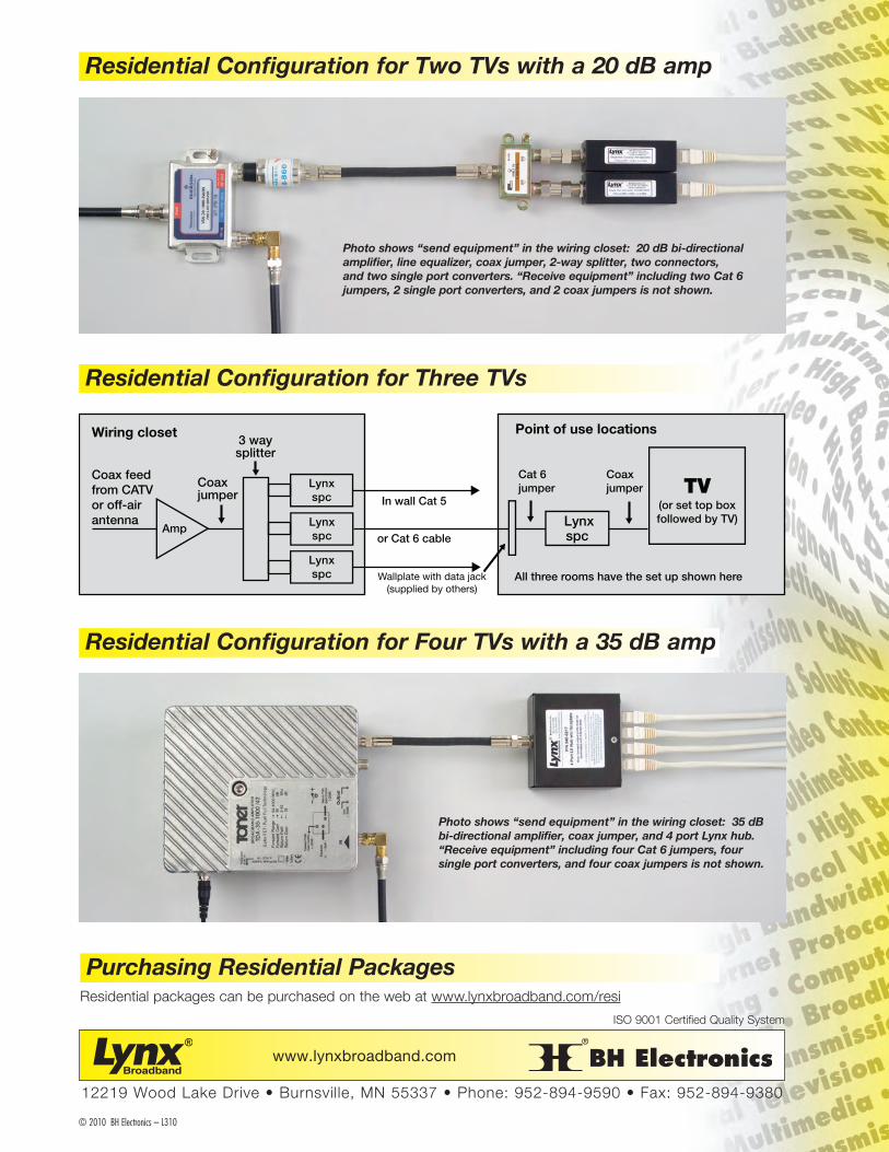
Residential Configuration for Two TVs with a 20 dB amp
Residential Configuration for Three TVs
Residential Configuration for Four TVs with a 35 dB amp
Photo shows “send equipment” in the wiring closet: 20 dB bi-directional amplifier, line equalizer, coax jumper, 2-way splitter, two connectors, and two single port converters. “Receive equipment” including two Cat 6 jumpers, 2 single port converters, and 2 coax jumpers is not shown.
TV(or set top box followed by TV)
Coaxjumper
Cat 6jumper
In wall Cat 5
Coaxjumper
Coax feed from CATVor off-airantenna
Lynxspc
All three rooms have the set up shown here
Amp Lynxspc
Lynxspc
3 way splitter
Wiring closet
Lynxspc
Point of use locations
or Cat 6 cable
Wallplate with data jack(supplied by others)
Photo shows “send equipment” in the wiring closet: 35 dB bi-directional amplifier, coax jumper, and 4 port Lynx hub. “Receive equipment” including four Cat 6 jumpers, four single port converters, and four coax jumpers is not shown.