
teletower user manual RW7 - Best Ladders - Roof Ladders - …loftsandladders.co.uk/pdfs/teletower...
36
For use as a TOWER or a PODIUM Seven working heights TELETOWER® Instruction and Reference Manual for models TTA-01, TTA-01tb, TTF-02, TTF-02tb
Transcript of teletower user manual RW7 - Best Ladders - Roof Ladders - …loftsandladders.co.uk/pdfs/teletower...

For use as a TOWER or a PODIUM Seven working heights
TELETOWER®Instruction and Reference Manual
for models
TTA-01, TTA-01tb, TTF-02, TTF-02tb

INTRODUCTION
Thank you for purchasing the TELETOWER®.
The TELETOWER® is manufactured in aluminum with an anodised finish. It is built towithstand the toughest handling and working conditions. It is suitable for DIY, tradeand professional applications. Spare parts are readily available.
You may already be familiar with using similar equipment but the TELETOWER® isunique and we recommend you to take time and read these instructions. They aredesigned to familiarize you with the features of the system and to ensure you get thevery best performance from your purchase.
Keep these instructions in a safe place for future reference.
For more information about the TELETOWER® and other products, please visit thewebsite www.teletower.com
SAFETY
Please ensure you read the Safety section in this manual starting on page 4 beforeassembling or using the equipment. Your safety and that of others is important.
2
TELETOWER® Instruction and Reference Manual Issue 1
All rights reserved. No part of this publication may be reproduced, transmitted, transcribed, translated or stored in a retrievalsystem in any form by any means without the written permission of TELETOWER® Limited
Technical details contained in this publication are correct for the equipment model number supplied. The Instruction andReference Manual will be revised as necessary for subsequent revisions to the equipment. This information will also bepublished on our website. Copyright TELETOWER® 2011

CONTENTS
INTRODUCTION . . . . . . . . . . . . . . . . . . . . . . . . . . . . . . . . . . . . . . . . . . 2SAFETY . . . . . . . . . . . . . . . . . . . . . . . . . . . . . . . . . . . . . . . . . . . . . . 2IMPORTANT SAFETY INFORMATION . . . . . . . . . . . . . . . . . . . . . . . . . . . . . . 4
Safety Considerations . . . . . . . . . . . . . . . . . . . . . . . . . . . . . . . . . . . . . . 4Servicing and Spare Parts . . . . . . . . . . . . . . . . . . . . . . . . . . . . . . . . . . . . 4
MAIN FEATURES . . . . . . . . . . . . . . . . . . . . . . . . . . . . . . . . . . . . . . . . . 5IN THE BOX . . . . . . . . . . . . . . . . . . . . . . . . . . . . . . . . . . . . . . . . . . . . 6
Equipment and accessories supplied . . . . . . . . . . . . . . . . . . . . . . . . . . . . . . 6GETTING STARTED . . . . . . . . . . . . . . . . . . . . . . . . . . . . . . . . . . . . . . . . 7
Lock Indicator Buttons. . . . . . . . . . . . . . . . . . . . . . . . . . . . . . . . . . . . . . 7Castors/Stabilisers . . . . . . . . . . . . . . . . . . . . . . . . . . . . . . . . . . . . . . . . 7Deploying the ground stabiliser legs. . . . . . . . . . . . . . . . . . . . . . . . . . . . . . . 8
1. ERECTING THE SAFETY CAGE . . . . . . . . . . . . . . . . . . . . . . . . . . . . . . . . 92. FITTING THE PLATFORM . . . . . . . . . . . . . . . . . . . . . . . . . . . . . . . . . . . 123. FITTING THE TOE BOARDS . . . . . . . . . . . . . . . . . . . . . . . . . . . . . . . . . 144. DEPLOYING THE PLATFORM STABILISERS . . . . . . . . . . . . . . . . . . . . . . . . 155. SETTING THE PLATFORM HEIGHT . . . . . . . . . . . . . . . . . . . . . . . . . . . . . 17
Platform height 1.00 metre . . . . . . . . . . . . . . . . . . . . . . . . . . . . . . . . . . . 18Platform height 1.25 metre . . . . . . . . . . . . . . . . . . . . . . . . . . . . . . . . . . . 19Platform height 1.50 metre . . . . . . . . . . . . . . . . . . . . . . . . . . . . . . . . . . . 20Platform height 1.75 metre . . . . . . . . . . . . . . . . . . . . . . . . . . . . . . . . . . . 22Platform height 2.00 metre . . . . . . . . . . . . . . . . . . . . . . . . . . . . . . . . . . . 24
COLLAPSING THE TELETOWER® . . . . . . . . . . . . . . . . . . . . . . . . . . . . . . . 27PODIUM . . . . . . . . . . . . . . . . . . . . . . . . . . . . . . . . . . . . . . . . . . . . . 30SPECIFICATIONS . . . . . . . . . . . . . . . . . . . . . . . . . . . . . . . . . . . . . . . . 33WARRANTY . . . . . . . . . . . . . . . . . . . . . . . . . . . . . . . . . . . . . . . . . . . 34TELETOWER® COMPONENTS IDENTIFIED . . . . . . . . . . . . . . . . . . . . . . . . . . 35
3
4
IMPORTANT SAFETY INFORMATION
WARNING. For your safety, please read all the safety instructions in thisManual before using the TELETOWER®.
Safety and quality is of paramount importance when manufacturing TELETOWER®products. All products meet the requirements of the Work at Height Regulations of2005 and also comply with PASMA's recommendations relating to the safe method oftower building.
IMPORTANT. Read these instructions before assembling the TELETOWER®.
IMPORTANT. Always assemble the TELETOWER® according the instructions given inthis Manual and on the labels affixed to the TELETOWER®.
SAFETY CONSIDERATIONS
General
• Do not use the TELETOWER® if it is damaged in any way
• Never exceed the maximum load of 150 kg
• It is recommended that the platform is removed when adjusting the height
• It is recommended that the platform is removed when collapsing theTELETOWER®
• Never release two red buttons at the same time
• Never place hands or fingers between rungs when collapsing the TELETOWER®
• Always wear a hard hat when erecting or collapsing the TELETOWER®
Cleaning
• Do not use any abrasive or chemical solvents.
• Periodically clean with a soft bristle brush and wipe with a damp cloth. Werecommend occassionally spraying with a silicon spray
• The castors should be cleaned using a wet sponge and dried afterwards.
How do I dispose of this product?When the unit has reached the end of its life, contact your local councilregarding available recycling or disposal options.
SERVICING AND SPARE PARTSA full set of spares are available. Please visit our website for further details forServicing and Spare Parts.

MAIN FEATURES
The main features of the TELETOWER® are listed below.
• Manufactured in anodised Aluminum (models TTA-01 and TTA-01tb)
• Manufactured in Fibreglass (models TTF-02 and TTF-02tb)
• Can be used as a Tower or a Podium
• Has seven working height from 0.33m to 2m
• Five-position stabiliser legs with locking castors
• Can be erected in less than three minutes by a single person thereby savingdown time and man hours
• Folds down for ease of transportation and storage
• Easily transportable in a small van or estate car thereby reducing fuel costs
• Comprises only three parts (main assembly, platform and Toe boards)
• Conforms to EN1004
5

IN THE BOX
Carefully remove your TELETOWER® from the box it arrived in. It is recommended that
you retain this packaging should the item need to be returned under warranty.
EQUIPMENT AND ACCESSORIES SUPPLIED
There are four models of the TELETOWER®: TTA-01, TTA-01tb, TTF-02 and TTF-02tb .The il lus tra tions be low ap ply to model TTA-01tb where 'tb' in di cates toe boards aresup plied.
(1) The main assembly in collapsed form (with folded platform)
(2) Four lockable castors with adjustable stabilisers
(3) The Instruction and Reference Manual (This publication)
(4) Toe boards in carrying case (optional with TTA-01 and TTF-02))
6
1. Main assembly with folded platform
x4
x2
TeleTower
4. Toe boards. These are only supplied withthe TTA-01tb and TTF-02tb models.
(x4)
2.. Castors with stabilisers
3. The Instruction and Reference Manual

GETTING STARTED
LOCK INDICATOR BUTTONSThe red and yellow buttons are used to show that the lock mechanisms are engagedor not when erecting the TELETOWER®.
At all height settings, the yellow buttons should alwaysbe in the locked position i.e. guard rails should be inplace, see page 9. At the 2 metre height setting, allyellow and red buttons should be in their locked position.
The locking mechanism of a rung is situated at each endof the rung immediately below it.
As a rung is lifted, it automatically locks to the framewhen it is in the correct position. When this happens anaudible 'click' will be heard. At the same time the red oryellow buttons on the rung immediately below the onebeing lifted will move to the locked position, see theexample shown right.
Red Buttons The red buttons on the rungs are used to release the locking mechanism during thetime the TELETOWER® is being collapsed. There is a red release-button located neareach end of the rungs labelled RUNG 4, RUNG 5, RUNG 6 and RUNG 7. When abutton is activated by sliding it away from the end of the rung, the locking pin at thisposition is retracted which allows the rung immediately above (and any rungs and orstructures above this) to move downwards.
Yellow buttonsThe yellow buttons act in the same way as the red buttons and are used during thetime the TELETOWER® is being collapsed. The yellow release-buttons are located ateach end of RUNG 2 and RUNG 3. These buttons allow the erected safety cage to becollapsed.
CASTORS/STABILISERSA stabiliser leg is an integral part of each castor. In addition to providing a largermore stabilized foot print, the stabilisersare used to allow the TELETOWER® to beused on an uneven surfaces.
The stabiliser can be rotated through270 degrees. It can be locked in one of five positions set at 45 degree intervals.
The castors and adjustable stabiliser legs are supplied as a single item.
7
CASTOR SHAFT
CASTOR STABILISER LEGFOOT
STABILISERFOOT RELEASELEVER
CASTORLOCKING LEVER
ADJUSTER
RUNG 6
RUNG 5
RUNG 4
RUNG 3
RUNG 2
RUNG 1
THIS POSITION INDICATESTHAT RUNG 4 ABOVEIS LOCKED
THIS POSITION INDICATES RUNG
5 IS UNLOCKED
INDICATES RUNG 2 ABOVE IS LOCKED
INDICATES RUNG 3 IS NOT LOCKED

Fitting the castorsTo fit the castors carry out the following.
1. Carefully lay the fully collapsed main assembly (without platform) in a horizontalposition on the floor or on a bench.
2. Take a castor/stabiliser leg and slide the castor shaft into position on the mainassembly.
3. Push the red button on RUNG 9 away from the castor and push the castor shaftfully in and rotate until the castor is adjacent to rung 9.
4. Release the button and if necessary rotate it a little further until you hear thelock-pin click into place, which locks the stabiliser in this position.
5. Push down on the stabiliser release lever and lift the stabiliser foot until it is fullyretracted, and then release the lever. This will allow the stabiliser leg to be clear ofthe ground when the main assembly is returned to its upright position.
6. Repeat for the other castors and return the TELETOWER® to its upright position.
Deploying the ground stabiliser legsThe ground stabiliser legs should be deployed when the TELETOWER® has been fullyerected at the required platform height.
1. To move it into place, unlock the castors and push it to the working position.
2. Lock the castors by pushing down on the locking lever with your foot.
3. Slide the red button closest to the ground stabiliser towards the centre of RUNG 9and rotate the stabiliser until it is near the required position. Release the buttonand rotate a little further either way until you hear the locking mechanism click in.
4. Deploy a ground stabiliser foot by pressing down on the Adjuster until the foot isin contact with the surface. Turn the adjuster to tighten it to be in good contactwith the ground. Repeat for the other ground stabilisers as required or allowed.
5. Check that the castors and ground stabiliser legs are secure and locked beforeusing the TELETOWER®.
8
CASTORRELEASEBUTTON
STABILISER FOOTRELEASE LEVER
PART OFFRAME
CASTORFOOT
CASTORLOCKINGLEVER
ADJUSTER
CASTORSHAFT

1. ERECTING THE SAFETY CAGE
This procedure starts from when the TELETOWER® is in its fully collapsed arrangement,with castors fitted as in Figure 1.1.
1. Ensure the castors are unlocked and the wheels are free to rotate.
2. Release the two fabric straps fastened around the legs of the assembly that holdthe two frames together.
3. While keeping the frames together at the back, pushthe front legs slightly apart as shown in Figure 1.2.
4. Lift and withdraw the folded platform and put it to one side.
5. Unfold the TELETOWER® and straighten the yellowgate keeping the side frames parallel until the gatelocks. You will hear it click-lock. Check that the gateis locked.
6. Swing the two side frames so they are each at 90degrees to the gate and then lock the four castors byusing your foot to push the locking lever down on allfour castors.
9
1.2
RUNG 7
RUNG 9
RUNG 8
RUNG 1
RUNG 3RUNG 4RUNG 5RUNG 6
RUNG 2
LOCKINGGATE
Not locked
ADJUSTABLE HAND-RAIL
ADJUSTABLE KNEE-RAIL

LIFTING1. Hold both ends of RUNG 1 (Figure 1.3)
and place one foot on RUNG 9. LiftRUNG 1 until it locks in place. A clickwill be heard when it locks and theyellow buttons on RUNG 2 shouldthen be in the locked position. Thishas lifted the hand guardrail, seeFigure 1.3.
2. Now hold both ends of RUNG 2. Place one foot on RUNG 9 and lift RUNG 2 un tilit locks in place, Fig ure 1.4. This is in di cated by the yel low but tons on RUNG 3be ing in the locked po si tion. This has lifted the hand and knee guard rails intoposition, see Figure 1.4.
3. Repeat steps (1) and (2) on the opposite frame of the TELETOWER®.
Note. There is a pair of hand rails and a pair of knee-rails on the left and right frames of the TELETOWER®. The lower part of each pair comprises a side rail,RUNG 1 and RUNG 2 (fixed), and the upper parts, adjustable hand-rail andadjustable knee-rail (movable). The latter is the front rail or the rear rail (rear on theleft frame, front on the right frame).
10
RUNG 3RUNG 4RUNG 5RUNG 6
RUNG 7
RUNG 3RUNG 4RUNG 5RUNG 6RUNG 7
RUNG 3RUNG 4RUNG 5RUNG 6RUNG 7
RUNG 1 RUNG 1
RUNG 2
RUNG 1
RUNG 9
RUNG 8
LOCKINGGATE
LOCKINGGATE
RUNG 9 RUNG 9
RUNG 8 RUNG 8
RUNG 1
RUNG 2
LOCKINGGATE
Click Click
Click
Click Click
Locked Locked
Not locked
Locked Locked
RUNG 3RUNG 4RUNG 5RUNG 6
RUNG 7
RUNG 3RUNG 4RUNG 5RUNG 6RUNG 7
RUNG 3RUNG 4RUNG 5RUNG 6RUNG 7
RUNG 1 RUNG 1
RUNG 2
RUNG 1
RUNG 9
RUNG 8
LOCKINGGATE
LOCKINGGATE
RUNG 9 RUNG 9
RUNG 8 RUNG 8
RUNG 1
RUNG 2
LOCKINGGATE
Click Click
Click
Click Click
Locked Locked
Not locked
Locked Locked
1.3
1.4

FRONT AND REAR RAILS1. Hold the yellow cover on the end of an upper handrail using your thumb and
fingers, and push it towards the end of the rail. Hold it in this position while you lift the end to unfasten it from its anchor point, see Figure 1.5.
2. Rotate the anchor point through 90 degrees to face the opposite side frames, seeFigure 1.6.
3. Rotate the rail end towards the opposite frame.
4. Extend the rail until you hear two clicks. This tells you that the 3-part rail has been securely locked in its extended position. Carefully let the rail hang down from theattached end.
Note. You should be able to see the ball-bearings from the locking mechanismprotruding from the side walls of the rail.
5. Repeat steps 1 to 4 for the other guardrails.
6. Lift one of the extended rails above its new anchor point on the opposite frameand push down to lock in place.
7. Repeat for the other three rails to complete the erection of the Safety Cage,Figure 1.7.
8. The Safety Cage can remain 'built' until theTELETOWER® is collapsed.
11
1.6
ROTATEROTATE

2. FITTING THE PLATFORM
WARNING. The platform must ALWAYS be mounted on RUNG 3 exceptwhen the TELETOWER® is being used in "PODIUM" mode.
1. Fully unfold the platform until it is straight. It will lock straight automatically. Ensure it has locked in this position, see Figure 2.1.
2. The platform has four location brackets fitted one near each corner on theunderside to correctly locate and secure the platform on the rung as shown inFigure 2.1 and Figure 2.2. RUNG 3 has two locator guides on the inner face of the rung for positioning the platform correctly, see Figure 2.3.
WARNING. When lifting the platform, hold the side frames only. Take careNOT to hold it via the underside panel as there is a trapdoor in the panel.This will open if you try to support the weight of the platform at this point.
12
RUNG 3
PLATFORM
LOCATIONBRACKET
LOCATIONBRACKET
LOCATIONBRACKET GUIDE(1 OF 4)
RUNG 3
PLATFORM
2.3
Always place Platform at this level3
RUNG
1.00m
TRAP DOOR
LOCATIONBRACKETS
LOCATIONBRACKET
LOCATIONBRACKET(HIDDEN)
TOE BOARDFIXING BRACKET
TOE BOARDFIXING BRACKETS
LOCKING HINGE
RELEASE LEVER
HOLD SIDE FRAME HEREWHEN LIFTING PLATFORM
HOLD SIDE FRAME HEREWHEN LIFTING PLATFORM
TOE BOARDFIXING BRACKET
2.1
2.2

3. Grip the platform along its sides andplace it on RUNG 3 on both left andright frames ensuring the platformlocation brackets sit over the rungand sit inside the location bracketguides on the rung.
4. The platform has two spring-loadedsafety catches located one at eachend on the underside which whenset secures the platform to RUNG 3. [Fig 2.4]. Pull the tab onto thelocking pin on each RUNG 3.
5. The platform level is 1 metre, see Figure 2.5.
13
PLATFORM
TOE BOARD
LOCKINGGATE
RUNG 9
RUNG 8
HANDRAILLOCKED
HANDRAILLOCKED
KNEERAILLOCKED
KNEERAILLOCKED
RUNG 3RUNG 4RUNG 5RUNG 6RUNG 7
HANDRAIL
RUNG 2
KNEERAIL
2.5
RUNG 3
PLATFORMLOCKPLATFORM
2.4

3. FITTING THE TOE BOARDThe Toe board is supplied as six sections in a canvas carry bag with Toe board fixingbrackets (x8) and cross-head screws (x32). Screw the brackets into the tapped holesalong the side of the platform as shown in Figure 3.1. The Toe boards are suppliedready to use. Figure 3.1 shows the front Toe boards being fitted.
The front and rear boards have locating pins fitted which engage with the Toe boardbrackets on the edge of the platform. Note that the rails use different spacing between the locating pins. The side toe boards do not have pins but each have four hooked -shaped lugs that engage with slots in the edges of the front and rear toe boards.
1. Take a section fitted with pins andalign the pins with the receptacles(from above) and lower it into place,Figure 3.1.
2. Repeat for the other three sectionswith pins.
3. Take a side Toe board and align thelugs with the slots in the front/reartoe boards, see Figure 3.2.
4. Lift the front and then the rear Toeboards a little (1). Guide the lugsinto the slots (2). Lower the front and rear toe boards (3) to lock together.The side toe board cannot now beremoved without lifting the front andrear toe boards.
5. Repeat for the other side toe boardto complete.
14
TOE BOARDFIXING BRACKET
TOE BOARDFITTED
FRONT OR REARTOE BOARD
PLATFORM
TOE BOARD FIXING BRACKET
CLOSE UP OF TOE BOARD
BRACKET
SLOPINGSURFACE(TOP)
3.1
1 3
SIDETOE BOARD
REARTOE BOARD
FRONTTOE BOARD LOCATING
PINS
2
3.2

4. DEPLOYING THE PLATFORM STABILISERS
The platform is equipped with four platform stabilisers (braces) which are stowed onthe underside of the platform, see Figure 4.1.
WARNING. The platform stabilisers MUST be deployed when the platformworking height is at or greater than 1.50 metres.
Press the release button at the far end of the stabiliser and pull back on the yellowlever to release it from the stowage bracket. The stabilisers are hinged centrally on the platform and when deployed anchor to brackets on the inner face of RUNGS 5, 6 & 7.
The stabilisers are telescopic in construction and adjustable to three different lengthsto suit the three platform heights that require platform stabilisers to be used. The freeend has a spring self-locking slot, see Figure 4.2.
There is a spring-loaded ball locking mechanism which holds the stabiliser at any ofthe three preset extensions. The stabiliser has a viewing window in its side that letsyou easily adjust it to the correct length using a colour coded system. The bracketsare also coloured, see Figure 4.3.
15
PLATFORMSTABILISERSTOWED
PLATFORM STABILISERSTOWAGE BRACKET
PULL LEVER TO RELEASE STABILISER
PLATFORM
LOCKING BALLMECHANISM
PUSH DOWN TORELEASE THELOCK
EXTENSION POSITIONS
4.1
4.2

• For a 2.00 metre platform height use the redcoloured bracket with the stabiliser extended to show red in the viewing window.
• For 1.75 metre platform height use the yellow coloured bracket with the stabiliser extended to show yellow in the viewing window.
• For a 1.50 metre platform height use the blue coloured bracket with the stabiliser extended to show blue in the viewing window.
When the TELETOWER® has been erected to there quired height, and the plat form fit ted, ex tend a plat form sta bi liser un til the re quired col our isseen in the view ing win dow on the side of thesta bi liser. This should be the same as the col our of the bracket it is to con nect to. At this timeyou will hear a click that in di cates the sta bi liseris locked at the required length.
Figure 4.4 and Figure 4.5 shows an example ofa platform stabiliser deployed when the platform height is 1.75 metres.
The correct bracket is always two rungs belowthe platform. Firmly push the stabiliser end ontothe bracket. Check that it has locked. Repeat for the other three stabilisers.
RELEASING THE STABILISERSTo release a platform stabiliser, press the yellowlever on the end of the stabiliser and lift the endoff the bracket. The locking ball bearing will beprotruding since the stabiliser will be extendedand locked. Depress the protruding ball bearingon the underside of the stabiliser and retract the stabiliser when preparing to stow it. This actionmay need to be repeated according to how farthe stabiliser was extended. Return the stabiliser to its stowed position and pull the yellow levertowards the stowage bracket until a click isheard from the pivoted end as it is locked underthe stowage bracket. Repeat for the otherstabilisers.
16
STABILIZER BRACKETS
2 METREPLATFORMHEIGHT
1.75 METREPLATFORMHEIGHT
1.50 METREPLATFORM HEIGHT
STABILIZER BRACKETS
2 METREPLATFORMHEIGHT
1.75 METREPLATFORMHEIGHT
1.50 METREPLATFORM HEIGHT
STABILIZER BRACKETS
2 METREPLATFORMHEIGHT
1.75 METREPLATFORMHEIGHT
1.50 METREPLATFORM HEIGHT
4.3
HINGED
HOOK ONTO THE BRACKET ON THE RUNG WHEN ATTHE REQUIRED LENGTH
VIEWING WINDOW
DEPRESS AND EXTENDUNTIL THE REQUIRED COLOUR IS DISPLAYED IN THE WINDOW
4.5
4.4
YELLOW BRACKET
YELLOW IN WINDOW

5. SETTING THE PLATFORM HEIGHT
Decide upon the platform height you require. This is important since the next stagevaries according to the required platform height.
WARNING. Although it is possible to erect the TELETOWER® with theplatform in situ, it is strongly recommended that the platform is ALWAYSfitted when the TELETOWER® is at the required height.
WARNING. The platform must ALWAYS be removed prior to lowering theTELETOWER® .
WARNING. When you wish to change from one platform height to another,you are recommended to remove the platform, lower the TELETOWER®until the platform height is at 1.00 metre and then follow the procedure toerect it to the height required.
• For a platform height of 1.00 metre, follow the procedure on page 18.
• For a platform height of 1.25 metre, follow the procedure on page 19.
• For a platform height of 1.50 metre, follow the procedure on page 21.
• For a platform height of 1.75 metre, follow the procedure on page 22.
• For a platform height of 2.00 metre, follow the procedure on page 24.
17
Always place Platform at this level3
RUNG
1.00m

PLATFORM HEIGHT 1.00 METRE
1. Erect the Safety Cage as described on pages 9 to 11.
Refer to the diagram below.
2. Attach the Platform to RUNG 3 as described on page 12 and 13.
3. Fit the Toe boards as described on page 14.
4. Deploy the ground stabiliser legs as described on page 8.
18
Always place Platform at this level3
RUNG
1.00m
PLATFORM
TOE BOARD
LOCKINGGATE
RUNG 9
RUNG 8
HANDRAILLOCKED
HANDRAILLOCKED
KNEERAILLOCKED
KNEERAILLOCKED
RUNG 3RUNG 4RUNG 5RUNG 6RUNG 7
HANDRAIL
RUNG 2
KNEERAIL

PLATFORM HEIGHT 1.25 METRE
1. Erect the Safety Cage as described on pages 9 to 11.
2. Place your foot on RUNG 9 and lift RUNG 6 as shown below to engage thelocking mechanism on RUNG 7.
3. Attach the Platform to RUNG 3 as described on pages 12 and 13.
4. Fit the Toe boards as described on page 14.
5. Deploy the ground-stabiliser legs as described on page 8.
19
RUNG 3RUNG 4RUNG 5RUNG 6RUNG 7
RUNG 3RUNG 4RUNG 5
RUNG 2
RUNG 2
RUNG 6
RUNG 7
‘Click’ ‘Click’
RUNG 1
RUNG 1
LOCKINGGATE
LOCKINGGATE
RUNG 9 RUNG 9
RUNG 8 RUNG 8
LOCKED
LOCKED LOCKED
LOCKED
Platform Height Lift this rung
6RUNG
1.25m

PLATFORM HEIGHT 1.50 METRE
1. Erect the Safety Cage as described on pages 9 to 11.
Refer to the diagrams on page 21.
2. Place your foot on RUNG 9 and lift RUNG 5 on the LEFT frame until locked.
3. Place your foot on RUNG 9 and lift RUNG 5 on the RIGHT frame until locked.
4. Place your foot on RUNG 9 and lift RUNG 6 on the RIGHT frame until locked.
5. Place your foot on RUNG 9 and lift RUNG 6 on the LEFT frame until locked.
6. Attach the Platform to RUNG 3 as described on pages 12 and 13.
7. See 'Deploying the Platform Stabilisers' described on pages 15 and 16.
Extend and lock a platform stabiliser above the rung containing the BLUE bracketuntil BLUE shows in the viewing window in the stabiliser. Ensure it is locked.
8. Place the stabiliser hook over the BLUE bracket and push down to lock it inplace.
9. Repeat steps (7) and (8) for the other platform stabilisers.
10. Fit the Toe boards as described on page 14.
11. Deploy the ground-stabiliser legs as described on page 8.
20
Platform Height Lift this rung then rung 6
5RUNG
1.50m

PLATFORM HEIGHT 1.50 METRE
21
RUNG 3
RUNG 3
RUNG 3RUNG 4RUNG 5RUNG 6RUNG 7
RUNG 4
RUNG 4
RUNG 5
LIFT RUNG 5
RUNG 6RUNG 7RUNG 7
RUNG 1
RUNG 2
LIFT RUNG 6
‘Click’ ‘Click’‘Click’ ‘Click’
LOCKED LOCKEDLOCKED LOCKED
LOCKINGGATE
LOCKINGGATE
LOCKINGGATE
RUNG 9 RUNG 9 RUNG 9
RUNG 8RUNG 8RUNG 8
Locked
Platform Height Lift this rung then rung 6
5RUNG
1.50m
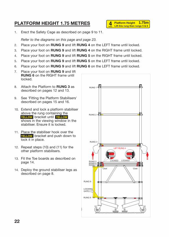
PLATFORM HEIGHT 1.75 METRES
1. Erect the Safety Cage as described on page 9 to 11.
Refer to the diagrams on this page and page 23.
2. Place your foot on RUNG 9 and lift RUNG 4 on the LEFT frame until locked.
3. Place your foot on RUNG 9 and lift RUNG 4 on the RIGHT frame until locked.
4. Place your foot on RUNG 9 and lift RUNG 5 on the RIGHT frame until locked.
5. Place your foot on RUNG 9 and lift RUNG 5 on the LEFT frame until locked.
6. Place your foot on RUNG 9 and lift RUNG 6 on the LEFT frame until locked.
7. Place your foot on RUNG 9 and liftRUNG 6 on the RIGHT frame untillocked.
8. Attach the Platform to RUNG 3 asdescribed on pages 12 and 13.
9. See 'Fitting the Platform Stabilisers'described on pages 15 and 16.
10. Extend and lock a platform stabiliser above the rung containing theYELLOW bracket until YELLOW shows in the viewing window in thestabiliser. Ensure it is locked.
11. Place the stabiliser hook over the YELLOW bracket and push down tolock it in place.
12. Repeat steps (10) and (11) for theother platform stabilisers.
13. Fit the Toe boards as described onpage 14.
14. Deploy the ground stabiliser legs asdescribed on page 8.
22
Platform Height Lift this rung then rungs 5 & 6
4RUNG
1.75m
RUNG 3RUNG 4RUNG 5RUNG 6RUNG 7
RUNG 3
RUNG 2
RUNG 2
RUNG 2RUNG 1
RUNG 1
RUNG 1
RUNG 5RUNG 6RUNG 7
RUNG 3
RUNG 4
RUNG 6RUNG 7
RUNG 3RUNG 4
RUNG 5
RUNG 7
LIFT RUNG 6
‘Click’
LOCKED LOCKED
Locked
LOCKED LOCKED
LOCKED LOCKED
LOCKINGGATE
RUNG 9
RUNG 8
LOCKINGGATE
RUNG 9
RUNG 8
LOCKINGGATE
RUNG 9
RUNG 8
LOCKINGGATE
RUNG 9
RUNG 8
LIFT RUNG 5
LIFT RUNG 4
‘Click’ ‘Click’‘Click’ ‘Click’
RUNG 2
RUNG 1
‘Click’

PLATFORM HEIGHT 1.75 METRES
23
RUNG 3RUNG 4RUNG 5RUNG 6RUNG 7
RUNG 3
RUNG 2
RUNG 2
RUNG 2RUNG 1
RUNG 1
RUNG 1
RUNG 5RUNG 6RUNG 7
RUNG 3
RUNG 4
RUNG 6RUNG 7
RUNG 3RUNG 4
RUNG 5
RUNG 7
LIFT RUNG 6
‘Click’
LOCKED LOCKED
Locked
LOCKED LOCKED
LOCKED LOCKED
LOCKINGGATE
RUNG 9
RUNG 8
LOCKINGGATE
RUNG 9
RUNG 8
LOCKINGGATE
RUNG 9
RUNG 8
LOCKINGGATE
RUNG 9
RUNG 8
LIFT RUNG 5
LIFT RUNG 4
‘Click’ ‘Click’‘Click’ ‘Click’
RUNG 2
RUNG 1
‘Click’
Platform Height Lift this rung then rungs 5 & 6
4RUNG
1.75m

PLATFORM HEIGHT 2.00 METRES
1. Erect the Safety Cage as described on pages 9 to 11.
Refer to the diagrams on page 25 and 26.
2. Place your foot on RUNG 9 and lift RUNG 3 on the LEFT frame until locked.
3. Place your foot on RUNG 9 and lift RUNG 3 on the RIGHT frame until locked.
4. Place your foot on RUNG 9 and lift RUNG 4 on the RIGHT frame until locked.
5. Place your foot on RUNG 9 and lift RUNG 4 on the LEFT frame until locked.
6. Place your foot on RUNG 9 and lift RUNG 5 on the LEFT frame until locked.
7. Place your foot on RUNG 9 and lift RUNG 5 on the RIGHT frame until locked.
8. Place your foot on RUNG 9 and lift RUNG 6 on the RIGHT frame until locked.
9. Place your foot on RUNG 9 and lift RUNG 6 on the LEFT frame until locked.
10. Attach the Platform to RUNG 3 as described on pages 12 and 13.
11. See 'Fitting the Platform Stabilisers' described on pages 15 and 16.
12. Extend and lock a platform stabiliser above the rung containing the RED bracketuntil RED shows in the viewing window in the stabiliser. Ensure it is locked.
13. Place the stabiliser hook over the RED bracket and push down to lock it in place.
14. Repeat steps (12) and (13) for each of the other platform stabilisers.
15. Fit the Toe boards as described on page 14.
16. Deploy the ground stabiliser legs as described on page 8.
24
Platform Height Extend rungs 3, 4, 5 and 6
7RUNG
2.00m

PLATFORM HEIGHT 2.00 METRES
25
LOCKINGGATE
RUNG 9
RUNG 8
LOCKINGGATE
RUNG 9
RUNG 8
LOCKINGGATE
RUNG 9
RUNG 8
LIFT RUNG 3
LOCKED LOCKED
‘Click’ ‘Click’
LIFT RUNG 4
‘Click’
LOCKED LOCKED
‘Click’
LIFT RUNG 5
‘Click’ ‘Click’
LIFT RUNG 6
‘Click’ ‘Click’
LOCKEDLOCKED
RUNG 1
RUNG 1
RUNG 1
RUNG 1
RUNG 2
RUNG 2
RUNG 7
RUNG 4
RUNG 4
RUNG 3
RUNG 3
RUNG 3
RUNG 2
RUNG 2
RUNG 5
RUNG 6RUNG 7
RUNG 4RUNG 5RUNG 6RUNG 7
RUNG 5RUNG 6RUNG 7
LOCKINGGATE
RUNG 9
RUNG 8
LOCKEDLOCKED
Platform Height Extend rungs 3, 4, 5 and 6
7RUNG
2.00m

PLATFORM HEIGHT 2.00 METRES
26
Platform Height Extend rungs 3, 4, 5 and 6
7RUNG
2.00m
LOCKINGGATE
RUNG 9
RUNG 8
LOCKINGGATE
RUNG 9
RUNG 8
LOCKINGGATE
RUNG 9
RUNG 8
LIFT RUNG 3
LOCKED LOCKED
‘Click’ ‘Click’
LIFT RUNG 4
‘Click’
LOCKED LOCKED
‘Click’
LIFT RUNG 5
‘Click’ ‘Click’
LIFT RUNG 6
‘Click’ ‘Click’
LOCKEDLOCKED
RUNG 1
RUNG 1
RUNG 1
RUNG 1
RUNG 2
RUNG 2
RUNG 7
RUNG 4
RUNG 4
RUNG 3
RUNG 3
RUNG 3
RUNG 2
RUNG 2
RUNG 5
RUNG 6RUNG 7
RUNG 4RUNG 5RUNG 6RUNG 7
RUNG 5RUNG 6RUNG 7
LOCKINGGATE
RUNG 9
RUNG 8
LOCKEDLOCKED

6. COLLAPSING THE TELETOWER®
WARNING. The platform must ALWAYS be removed prior to collapsing theTELETOWER®.
1. Remove any tools or other items that are on the platform.
2. Remove the Toe board from the platform.
3. Unfasten the four Platform Stabilisers and stow under the platform as described on page 16.
4. Unfasten the two spring-catches that hold the platform to RUNG 3.
5. Carefully lift the Platform off each RUNG 3 and take the Platform to a safe placeaway from the TELETOWER®.
WARNING. Always begin collapsing TELETOWER® assembly by startingfrom RUNG 7.
REMEMBER. The red and yellow buttons operate as follows:
• The buttons on RUNG 7 release the locking mechanism for RUNG 6 whichallows RUNG 6 and all above to move down .
• The buttons on RUNG 6 release the locking mechanism for RUNG 5 whichallows RUNG 5 and all above to move down.
• The buttons on RUNG 5 release the locking mechanism for RUNG 4 whichallows RUNG 4 and all above to move down.
• The buttons on RUNG 4 release the locking mechanism for RUNG 3 whichallows RUNG 3 and all above to move down.
• The buttons on RUNG 3 release the locking mechanism for RUNG 2 whichallows RUNG 2 and all above to move down.
• The buttons on RUNG 2 release the locking mechanism for RUNG 1 whichallows RUNG 1 to move down.
27

WARNING. NEVER release the two buttons on a rung at the same time.
WARNING. NEVER place your hand or fingers on rungs that are beinglowered onto another rung, or on the rung you are lowering to.
The following procedure is for when the platform height is set at 2 metres. Not all ofthe following steps will apply to other platform heights.
Step 1 (On the left frame)
(a) With one hand hold the stile above RUNG 6 on the left frame prepare to take theweight of this and all above, see Figure 6.1.
(b) On RUNG 7, push one button towards the centre of RUNG 7 and then release the button.
(c) While still holding the stile above RUNG 6, push the button on the other end ofRUNG 7 towards the centre and then release the button and carefully lowerRUNG 6 onto RUNG 7.
(d) Repeat Step 1 (a) to (c) on the right frame.
Step 2 (Repeat as above for rung 5), but release the buttons on RUNG 6.
Step 3 (Repeat as above for rung 4), but release the buttons on RUNG 5.
Step 4 (Repeat as above rung 3), but release the buttons on RUNG 4.
Step 5. To collapse the Safet Cage, reverse the procedure given on pages 9 to 11that describes erecting the Safety Cage.
28
LOWER RUNG 6 (WITH ALL ABOVE )
GRIP AND SUPPORTALL ABOVELEFT HAND
RIGHT THUMB
STILE
LOCKINGGATE
RUNG 9
RUNG 8
RUNG 1
RUNG 7
RUNG 6
RUNG 4
RUNG 3
RUNG 2
RUNG 5
PUSH BUTTONSTOWARDS CENTRE
12
6.1

With the Safety Cage collapsed:
Step 6 (Repeat as above for rung 2), but release buttons on RUNG 3.
Step 7 (On the right frame)
(a) With one hand hold RUNG 1 on the left frame prepare to take the weight of this.
(b) On RUNG 2, push one button towards the centre of RUNG 2 and then release the button.
(c) While still holding RUNG 1, push the button on the other end of RUNG 2 towardsthe centre and then release the button and carefully lower RUNG 1 onto RUNG 2.
(d) Repeat Step 7 (a) to (c) on the left frame.
29

7. PODIUM
The Podium platform can be set at two heights, 61 cm and 33 cm as shown in theFigure 7.1 and Figure7.2 on page 31.
SETTING UP THE PODIUMThis procedure starts from when the TELETOWER® is in its fully collapsed arrangement,with castors fitted.
1. Ensure the castors are unlocked and the wheels are free to turn.
2. Unfasten the two fabric straps fastened around the legs of the frame assemblythat hold the equipment together and separate the side frames a little at the front.
3. Lift and withdraw the folded platform and put it to one side.
4. Unfold the frame assembly and straighten the yellow gate until the gate locks. You will hear it click-lock. Check that the gate is locked.
5. Swing the two side frames so they are each at 90 degrees to the yellow gate andthen lock the two castors on the left frame only using your foot to operate thelocking levers on the two castors.
6. Now move the front of the right hand frame slightly outwards. This helps in placing the platform location brackets on either RUNG 8 or RUNG 9 according to thepodium height required.
7. Fully unfold the platform until it is straight. It will lock straight automatically. Ensure it has locked in this position. The platform has four location brackets fitted onenear each corner on the underside that fit over the rung to hold the platform inposition. The platform can be fitted on either RUNG 9 (for 33cm platform height),or RUNG 8 (for 61 cm platform height) depending on the height required.
WARNING. When lifting the platform, take care NOT to hold it via theunderside panel as there is a trapdoor in the panel. This will open if youtry to support the weight of the platform at this point.
8. Support the platform and place the left-hand end on to the required rung on theleft hand frame. Now hold the opposite end of the platform pull the right handframe towards the platform and lower the platform onto RUNG 8 or RUNG 9according to the platform height you have chosen. Ensure the location bracketsare sitting correctly on the chosen rung.
See OPTION 1 Figure 7.1 or OPTION 2 Figure 7.2 on the next page which showsthe appearance when erected.
30

OPTION 1 and OPTION 2
1. Hold both ends of RUNG 1 and place one foot onRUNG 9.
2. Lift RUNG 1 until it locks in place. A click will beheard when it locks. This has lifted the hand guardrail.
3. Repeat steps (1) to (2) on the opposite frame.
Note. There are a pair of hand rails and knee rails on theleft and right frames of the TELETOWER®. The lower part of each pair comprises a fixed side rail, and an upperadjustable part. The front rail is on the right side and therear rail on the left.
4. Hold the yellow cover on the end of the left knee railusing your thumb and fingers, and push it towards itsend of the rail. Hold it in this position while you lift theend to unfasten it from its anchor point.
5. Rotate the anchor point through 90 degrees to facethe opposite side frame.
6. Rotate the rail end towards the opposite frame. See Figures 1.5 &1.6 on page 11.
7. Extend the rail until you hear two clicks. This tells you that the 3-part rail has been securely locked in its extended position. Carefully let the rail hang down and reston the platform.
8. Repeat steps (4) to (7) for the left handrail.
9. Repeat steps (4) to (7) for the front knee rail and front handrail to complete theerection of the safety cage.
Ground Stabilisers (both options)
1. Unlock the castors and push the Podium to its working position.
2. Lock the castors by pushing down on the locking lever with your foot.
3. On RUNG 9, slide the red button towards the centre of the rung and rotate thestabiliser leg until it is near the required position. Release the button and rotate the ground stabiliser a little further either way until you hear the locking mechanismclick in.
4. Repeat for the other three stabiliser legs.
5. Deploy a stabiliser leg by depressing its release lever until the base of the leg is incontact with the surface. Turn the adjuster to tighten and where necessary to raise the Podium to be horizontal. Repeat for the other stabiliser legs as required orallowed.
31
7.2
7.1
WARNING. Check that the castors and stabiliser legs are secure andlocked before using the Podium.
In useTo step onto the Podium,
1. Release the front hand-rail and the front knee-rail.
2. Take care and step up onto the platform.
3. Reconnect the front hand rail and knee rail.
32

SPECIFICATIONS
MAXIMUM LOAD 150 kg
WEIGHTSMain Assembly 41 kgPlatform 14 kgTotal 55 kg
PLATFORM HEIGHT(Options) 33cm, 61cm, 1.00m, 1.25m, 1.50m, 1.75m, 2.00m
DIMENSIONSFully collapsed 1.1 x 0.8 x 0.45m with castors fitted (Approx)ErectedPlatform height: Overall (h x w x d) m
2.00 m 2.94 x 1.5 x 0.92 m1.75 m 2.69 x 1.5 x 0.92 m1.50 m 2.44 x 1.5 x 0.92 m1.25 m 2.19 x 1.5 x 0.92 m1.00 m 1.94 x 1.5 x 0.92 m 61 cm 1.46 x 1.5 x 0.92 m 33 cm 1.46 x 1.5 x 0.92 m
CONSTRUCTION Aluminum (models TTA-01, TTA-01tb)Fibreglass (models TTF-02, TTF-02tb)
STANDARD Conforms to EN1004
33
Note. We reserve the right to change the specifications and design without notice in order to improve performance and quality.

34
WARRANTY
Your TELETOWER® is covered by a 12 month warranty. The Company undertakes toreplace or repair, free of charge, any defect which the Company considers to be due tofaulty workmanship or material within 12 months of the sale date, except for:
• Defects arising from neglect, misuse or unauthorised modifications.
• Damage caused by abuse, misuse, dropping or other similar damage caused by oras a result of failure to follow transportation, storage, loading or operation,instructions.
• Alterations, additions or repairs carried out by persons other than the Manufactureror their recognized distributors.
• Transportation or shipment costs to and from the Manufacturer or their recognizedagents, for repair or assessment against a warranty claim, on any TELETOWER® orcomponent.
• Materials and/or labour costs to renew, repair or replace components due to fair wear and tear.
• Faults arising from the use of non-standard or additional parts, or any consequentialdamage or wear caused by the fitting or use of such parts.
IMPORTANT–warranty may, at the sole discretion of the manufacturer, be voided if thescheduled service/inspections are not carried out in accordance with the service log book. The Manufacturer and/or their recognized agents, directors, employees or insurers willnot be held liable for consequential or other damages, losses or expenses in connectionwith, or by reason of, or the inability to use the TELETOWER® for any purpose.
MODIFICATIONS If additional equipment or any third party work, modifications or alterations are to becarried out on the TELETOWER® which will involve any welding, drilling or any form ofcutting or distortion of materials, full written approval must be obtained from theManufacturer prior to the work being carried out.
REPLACEMENT PARTS INFORMATION For information on replacement parts, visit our website where you can downloadillustrations and part listings.
www.TeleTower.com/technical/parts

TELETOWER® COMPONENTS IDENTIFIED
35
28
2
3
4
5
6
7
8
9
10
12
14
11
26
21
4
24
25
23
22
20
19
27
17
18
1
15
16
6
5
13
29
7
1. Front/rear hand rails2. Guard rail latch
3. Spring loaded lock/release button (yellow)
4. Front and rear toe boards (short)5 Side toe board
6 Front and rear toe boards (long)
7 Platform locking catch8. Spring loaded lock/release button (red)
9. Gate lock release button10. Ground stabiliser positioning red release button
11. Ground stabiliser
12. Ground stabiliser adjuster13. Ground stabiliser bar
14. Ground stabiliser bar release lever
15. Foot
16. Castor lock lever
17. Castor18. Stowage/transport securing straps
19. Platform stabiliser bars
20. Folding gate21. Platform stabiliser bracket (blue)
22. Stile 23. Platform stabiliser bracket (yellow)
24. Platform stabiliser bracket (red)
25. Platform 26. Hand rail / knee rail swivel anchors
27. Side hand-rail
28. Side knee-rail 29. Front/rear knee-rails