Telephony Lecture
23
TELEPHONY TABLE OF CONTENTS I. Telephony II. Switching System III. Subscribers’ Loop IV. Decibels and Noise Limits V. Telephone Traffic VI. Numbering Concepts VII. Signaling VIII. Frequency Division Multiplexing IX. Time Division Multiplexing Engr. Marlyn Quiambao-Camingal ECE
-
Upload
glenda-grageda -
Category
Documents
-
view
85 -
download
3
description
Notes in Telephony
Transcript of Telephony Lecture
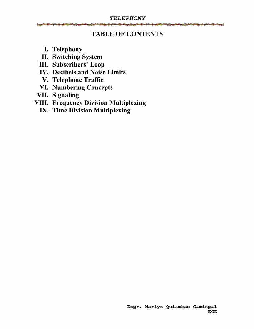
TELEPHONY
TABLE OF CONTENTS
I. Telephony II. Switching System
III. Subscribers’ Loop IV. Decibels and Noise Limits V. Telephone Traffic
VI. Numbering Concepts VII. Signaling
VIII. Frequency Division Multiplexing IX. Time Division Multiplexing
Engr. Marlyn Quiambao-Camingal ECE
TELEPHONY
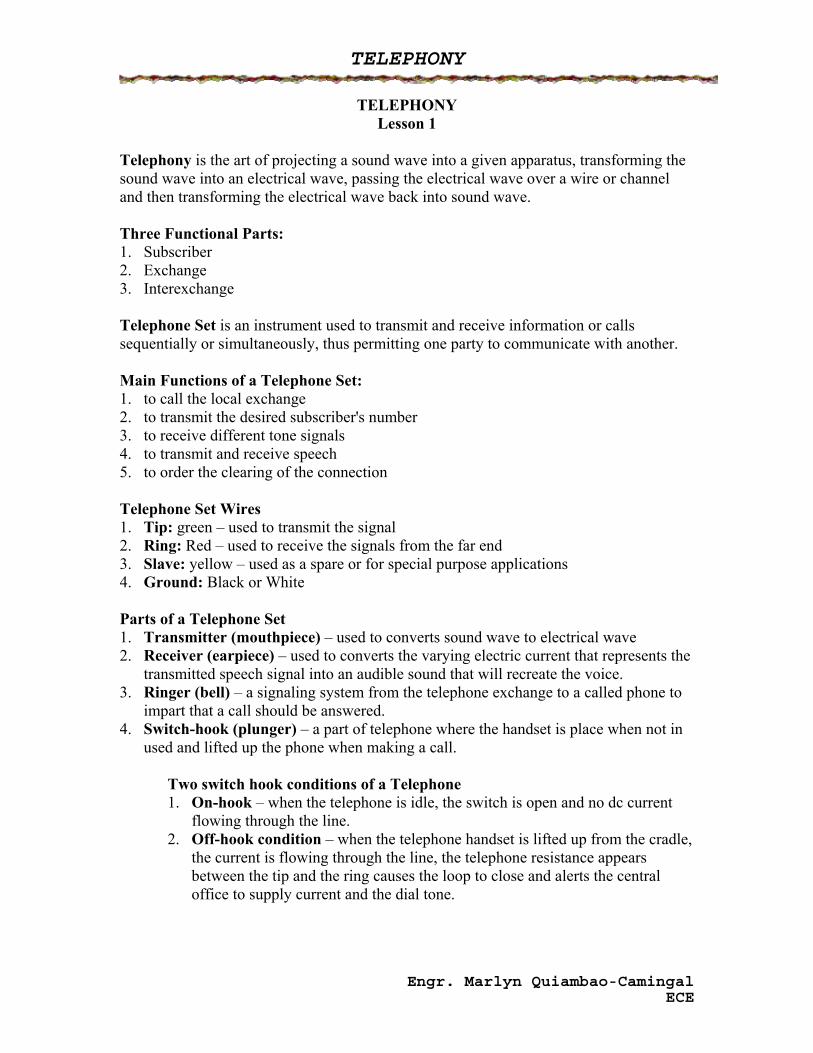
TELEPHONY Lesson 1
Telephony is the art of projecting a sound wave into a given apparatus, transforming the sound wave into an electrical wave, passing the electrical wave over a wire or channel and then transforming the electrical wave back into sound wave. Three Functional Parts: 1. Subscriber 2. Exchange 3. Interexchange Telephone Set is an instrument used to transmit and receive information or calls sequentially or simultaneously, thus permitting one party to communicate with another. Main Functions of a Telephone Set: 1. to call the local exchange 2. to transmit the desired subscriber's number 3. to receive different tone signals 4. to transmit and receive speech 5. to order the clearing of the connection Telephone Set Wires 1. Tip: green – used to transmit the signal 2. Ring: Red – used to receive the signals from the far end 3. Slave: yellow – used as a spare or for special purpose applications 4. Ground: Black or White Parts of a Telephone Set 1. Transmitter (mouthpiece) – used to converts sound wave to electrical wave 2. Receiver (earpiece) – used to converts the varying electric current that represents the
transmitted speech signal into an audible sound that will recreate the voice. 3. Ringer (bell) – a signaling system from the telephone exchange to a called phone to
impart that a call should be answered. 4. Switch-hook (plunger) – a part of telephone where the handset is place when not in
used and lifted up the phone when making a call.
Two switch hook conditions of a Telephone 1. On-hook – when the telephone is idle, the switch is open and no dc current
flowing through the line. 2. Off-hook condition – when the telephone handset is lifted up from the cradle,
the current is flowing through the line, the telephone resistance appears between the tip and the ring causes the loop to close and alerts the central office to supply current and the dial tone.
Engr. Marlyn Quiambao-Camingal ECE
TELEPHONY
5. Dialpad (keypad) – a part of telephone where a desire subscribers number can be dialed.
Dialing – referred to as addressing a telephone system. Two Type of Dialing
1. Pulse Dialing is defined as a momentary on-hook condition that causes loop making and breaking from the telephone set dialer toward the central office. Rotary dialpad is marked from 0 to 9 with each number representing a corresponding number of pulses that would be generated once the dial number is rotated from a starting position towards the fixed point.
State of Pulses: 1. Make – circuit closed/off hook, 4o % 2. Break – circuit opened/on-hook condition, 60 %
(make and break time =0.1 sec) 3. Interdigit delay – continuous make of 500 ms
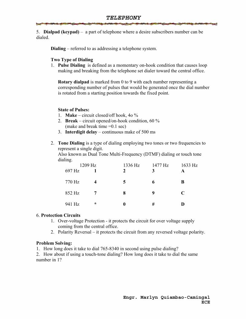
2. Tone Dialing is a type of dialing employing two tones or two frequencies to
represent a single digit. Also known as Dual Tone Multi-Frequency (DTMF) dialing or touch tone dialing.
1209 Hz 1336 Hz 1477 Hz 1633 Hz 697 Hz 1 2 3 A 770 Hz 4 5 6 B 852 Hz 7 8 9 C 941 Hz * 0 # D 6. Protection Circuits
1. Over-voltage Protection - it protects the circuit for over voltage supply coming from the central office.
2. Polarity Reversal – it protects the circuit from any reversed voltage polarity. Problem Solving: 1. How long does it take to dial 765-8340 in second using pulse dialing? 2. How about if using a touch-tone dialing? How long does it take to dial the same number in 1?
Engr. Marlyn Quiambao-Camingal ECE
TELEPHONY
SWITCHING Lesson 2
Switching a method of connecting the calling party to the called party.
Types of Switching: 1. Manual Control System – a call is being carried out by an operator using
switchboards and wires with jack. 2. Progressive Control or Step by Step Switching – also known as Strowger Switchig
System, named after the inventor Almon B. Strowger, 1889. It is the oldest automatic switching system, electromechanical in nature, in which intelligence is located in relays mounted on each switch.
It also known as direct control switch with three stages: 1. Line Equipment- includes the line finder 2. Switch Train – consists of selectors arranged to operate in a sequence
connecting the calling line to the connector group of the called line. 3. Connectors – are switches that complete the connection to the called party. 3. Common Control Switching
Also known as Crossbar Switching System. It is a switching system, still mechanical in nature but the intelligence of the system is separated from the actual switch.
It utilizes a switching matrix, which externally managed by common control, to route telephone calls.
4. Stored Program Control (SPC) or Electronic Switching System (ESS) Is the first generation ESS was employed in the year 1960.
It is a switching system control is in electronic circuit instead of mechanical devices, and the network or matrix is replaced with tiny glasss-encapsulated reed switches.
The final generation is known as digital switch. Features of digital switches:
1. Call waiting 2. Caller ID 3. Call forwarding 4. Teleconferencing 5. Abbreviated Dialing 6. Malicious Call Trace 7. Video conferencing 8. Automatic Call back 9. Call hold
Engr. Marlyn Quiambao-Camingal ECE
TELEPHONY
Exchange Hierarchy 1. International Exchange/Center – a center to which the tertiary centers are
connected to establish trunk connections and these center access the gateway facilities for international trunk connections.
2. Quarternary Exchange/Center – a center to which tertiary centers are connected to establish trunks connections
3. Tertiary Exchange/Center – a center to which secondary centers are connected to establish trunk connections.
4. Secondary Exchange/Center – a center to which the primary centers are connected to established a trunk connections
5. Primary Exchange/Center – a center to which local exchanges are connected and via which trunk connections are established
6. Local Exchange – an exchange of a local network to which the subscribers are directly or indirectly connected
7. Tandem Exchange/Center – an exchange used for connecting local exchange within a multi-exchange network.
Two Major Groups of Exchange 1. Public Network – anyone can be connected to it. 2. Private Network – telephone network privately owned by a certain organization.
Engr. Marlyn Quiambao-Camingal ECE
TELEPHONY
SUBSCRIBERS LOOP Lesson 3
Subscriber Loop- the connection between the telephone set and the central office switching equipment. Also known as local loop. Basic Subscriber Loop Design Requirements:
1. Enough power or current 2. An adjustable gain or loss in the loop 3. Minimum power loss 4. Minimum amount of noise, echo, crosstalk and any form of interference.
Rtotal = R tel + R cable + R misc + R switch I= 24 mA to 60 mA ( optimal value is 35 mA ) R tel = 150 (old) = 600 to 900 ohms ( new) Ohm’s Law: V=IR Where: R misc – resistance of the main distribution frame plus drop wire resistance (neglected) R tel – resistance of the telephone set R switch – switching office equipment resistance R cable – cable resistance used and varies according to size
Engr. Marlyn Quiambao-Camingal ECE
TELEPHONY
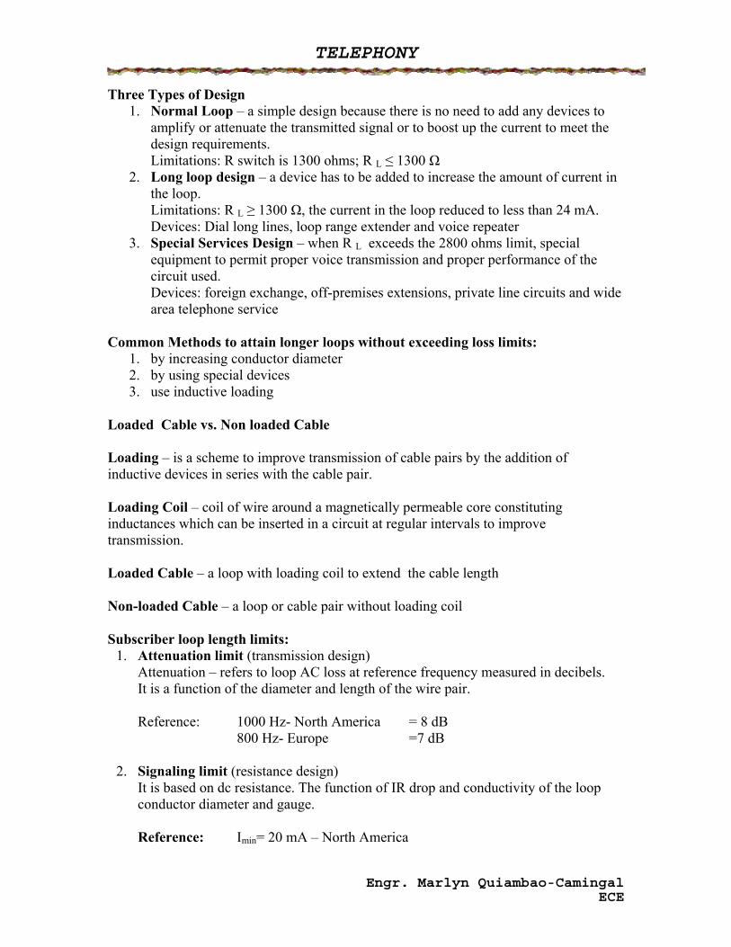
Three Types of Design 1. Normal Loop – a simple design because there is no need to add any devices to
amplify or attenuate the transmitted signal or to boost up the current to meet the design requirements. Limitations: R switch is 1300 ohms; R L ≤ 1300 Ω
2. Long loop design – a device has to be added to increase the amount of current in the loop. Limitations: R L ≥ 1300 Ω, the current in the loop reduced to less than 24 mA. Devices: Dial long lines, loop range extender and voice repeater
3. Special Services Design – when R L exceeds the 2800 ohms limit, special equipment to permit proper voice transmission and proper performance of the circuit used. Devices: foreign exchange, off-premises extensions, private line circuits and wide area telephone service
Common Methods to attain longer loops without exceeding loss limits:
1. by increasing conductor diameter 2. by using special devices 3. use inductive loading
Loaded Cable vs. Non loaded Cable Loading – is a scheme to improve transmission of cable pairs by the addition of inductive devices in series with the cable pair. Loading Coil – coil of wire around a magnetically permeable core constituting inductances which can be inserted in a circuit at regular intervals to improve transmission. Loaded Cable – a loop with loading coil to extend the cable length Non-loaded Cable – a loop or cable pair without loading coil Subscriber loop length limits:
1. Attenuation limit (transmission design) Attenuation – refers to loop AC loss at reference frequency measured in decibels. It is a function of the diameter and length of the wire pair. Reference: 1000 Hz- North America = 8 dB
800 Hz- Europe =7 dB
2. Signaling limit (resistance design) It is based on dc resistance. The function of IR drop and conductivity of the loop conductor diameter and gauge. Reference: Imin= 20 mA – North America
Engr. Marlyn Quiambao-Camingal ECE
TELEPHONY
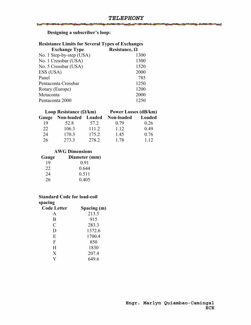
Designing a subscriber’s loop: Resistance Limits for Several Types of Exchanges
Exchange Type Resistance, Ω No. 1 Step-by-step (USA) 1300No. 1 Crossbar (USA) 1300No. 5 Crossbar (USA) 1520ESS (USA) 2000Panel 785Pentaconta Crossbar 1250Rotary (Europe) 1200Metaconta 2000Pentaconta 2000 1250
Loop Resistance (Ω/km) Power Losses (dB/km)
Gauge Non-loaded Loaded Non-loaded Loaded 19 52.8 57.2 0.79 0.26 22 106.3 111.2 1.12 0.49 24 170.3 175.2 1.45 0.76 26 273.3 278.2 1.78 1.12
AWG Dimensions
Gauge Diameter (mm) 19 0.91 22 0.644 24 0.511 26 0.405
Standard Code for load-coil spacing
Code Letter Spacing (m) A 213.5 B 915 C 283.3 D 1372.6 E 1700.4 F 850 H 1830 X 207.4 Y 649.6
Engr. Marlyn Quiambao-Camingal ECE
TELEPHONY
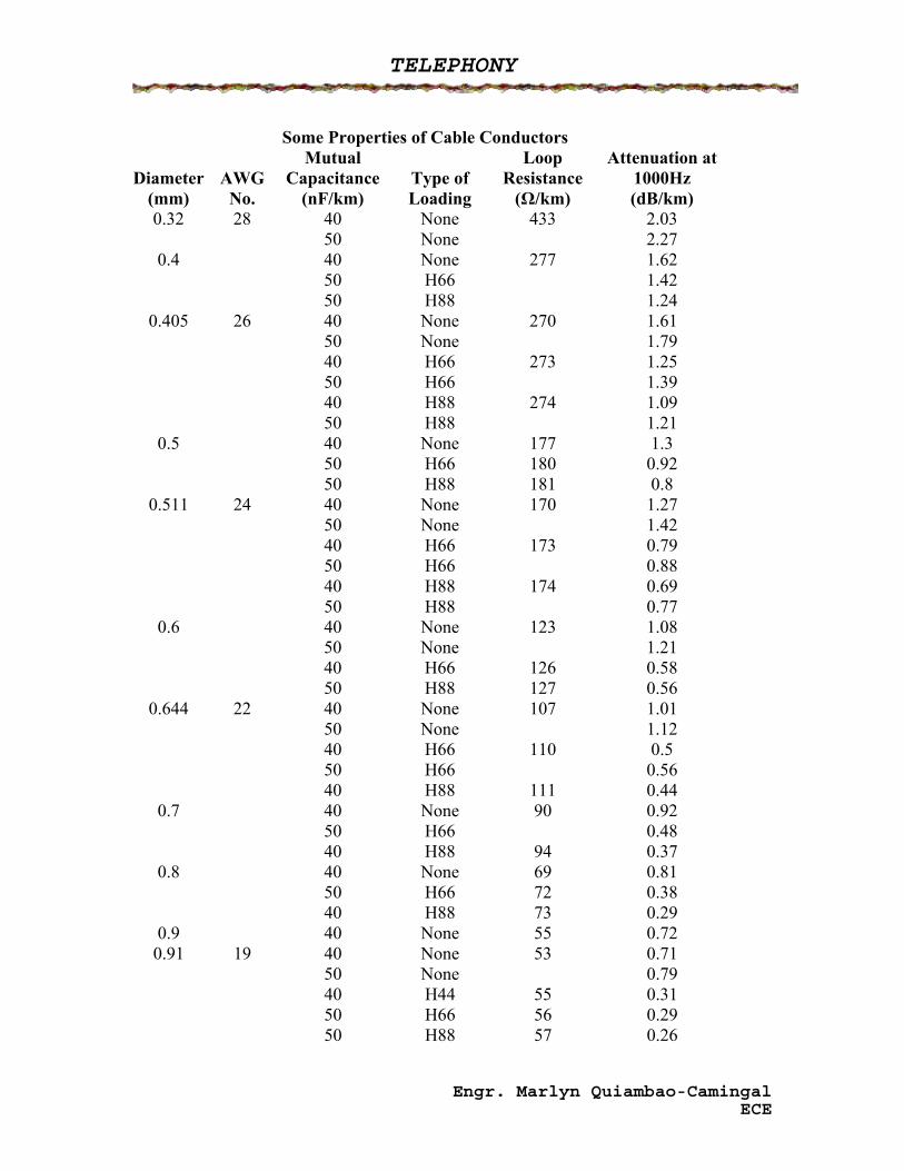
Some Properties of Cable Conductors
Diameter (mm)
AWG No.
Mutual Capacitance
(nF/km) Type of Loading
Loop Resistance
(Ω/km)
Attenuation at 1000Hz (dB/km)
0.32 28 40 None 433 2.03 50 None 2.27
0.4 40 None 277 1.62 50 H66 1.42 50 H88 1.24
0.405 26 40 None 270 1.61 50 None 1.79 40 H66 273 1.25 50 H66 1.39 40 H88 274 1.09 50 H88 1.21
0.5 40 None 177 1.3 50 H66 180 0.92 50 H88 181 0.8
0.511 24 40 None 170 1.27 50 None 1.42 40 H66 173 0.79 50 H66 0.88 40 H88 174 0.69 50 H88 0.77
0.6 40 None 123 1.08 50 None 1.21 40 H66 126 0.58 50 H88 127 0.56
0.644 22 40 None 107 1.01 50 None 1.12 40 H66 110 0.5 50 H66 0.56 40 H88 111 0.44
0.7 40 None 90 0.92 50 H66 0.48 40 H88 94 0.37
0.8 40 None 69 0.81 50 H66 72 0.38 40 H88 73 0.29
0.9 40 None 55 0.72 0.91 19 40 None 53 0.71
50 None 0.79 40 H44 55 0.31 50 H66 56 0.29 50 H88 57 0.26
Engr. Marlyn Quiambao-Camingal ECE
TELEPHONY
Problem Solving:
1. If the central office supply is -48 volts, the total resistance is 2400 ohms, the switching office and the telephone set resistances has 400 ohms and 300 ohms respectively. Considering a North American standard will the subscriber have dial tone? What is the maximum loop resistance in order to maintain the dial tone or other signaling element on the cable pair?
2. From the table, using 19 H 44 for the design of a subscriber loop for an 8 dB loss limit, determine the loop limit for this specification. How many inductive coil should be added and what is the resistance equivalent of each loading coil.
Engr. Marlyn Quiambao-Camingal ECE
TELEPHONY
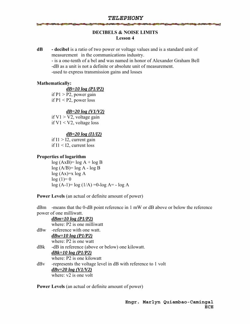
DECIBELS & NOISE LIMITS Lesson 4
dB - decibel is a ratio of two power or voltage values and is a standard unit of
measurement in the communications industry. - is a one-tenth of a bel and was named in honor of Alexander Graham Bell -dB as a unit is not a definite or absolute unit of measurement. -used to express transmission gains and losses Mathematically: dB=10 log (P1/P2) if P1 > P2, power gain if P1 < P2, power loss dB=20 log (V1/V2) if V1 > V2, voltage gain if V1 < V2, voltage loss dB=20 log (I1/I2) if I1 > I2, current gain if I1 < I2, current loss Properties of logarithm
log (AxB)= log A + log B log (A/B)= log A - log B log (Ax)=x log A log (1)= 0 log (A-1)= log (1/A) =0-log A= - log A
Power Levels (an actual or definite amount of power) dBm -means that the 0-dB point reference in 1 mW or dB above or below the reference power of one milliwatt. dBm=10 log (P1/P2)
where: P2 is one milliwatt dBw -reference with one watt.
dBw=10 log (P1/P2) where: P2 is one watt
dBk -dB in reference (above or below) one kilowatt. dBk=10 log (P1/P2) where: P2 is one kilowatt
dBv -represents the voltage level in dB with reference to 1 volt dBv=20 log (V1/V2) where: v2 is one volt
Power Levels (an actual or definite amount of power)
Engr. Marlyn Quiambao-Camingal ECE
TELEPHONY
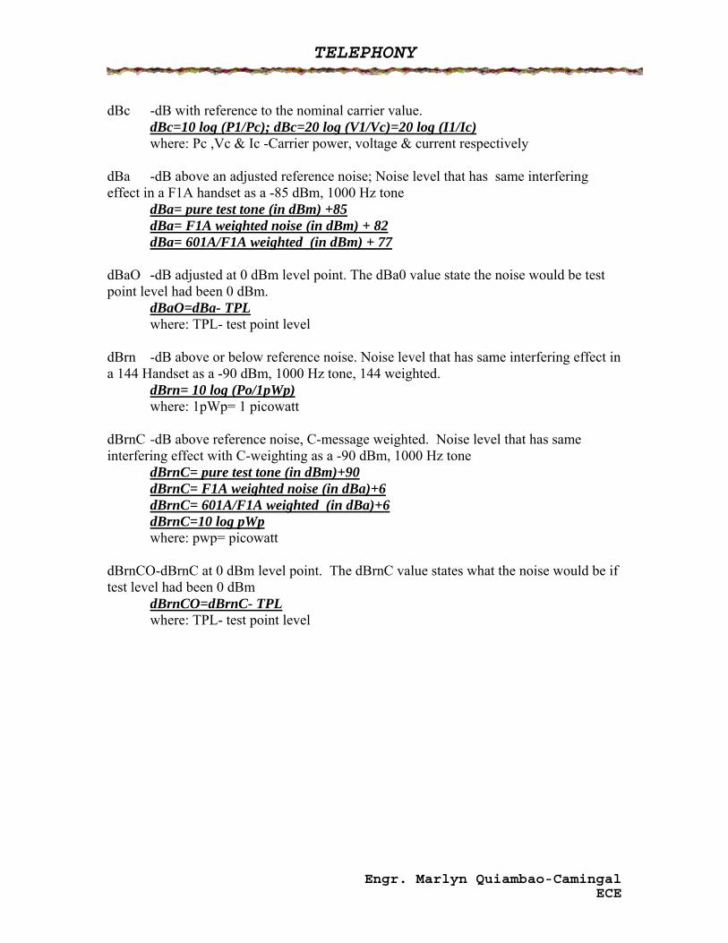
dBc -dB with reference to the nominal carrier value. dBc=10 log (P1/Pc); dBc=20 log (V1/Vc)=20 log (I1/Ic)
where: Pc ,Vc & Ic -Carrier power, voltage & current respectively dBa -dB above an adjusted reference noise; Noise level that has same interfering effect in a F1A handset as a -85 dBm, 1000 Hz tone
dBa= pure test tone (in dBm) +85 dBa= F1A weighted noise (in dBm) + 82 dBa= 601A/F1A weighted (in dBm) + 77
dBaO -dB adjusted at 0 dBm level point. The dBa0 value state the noise would be test point level had been 0 dBm.
dBaO=dBa- TPL where: TPL- test point level
dBrn -dB above or below reference noise. Noise level that has same interfering effect in a 144 Handset as a -90 dBm, 1000 Hz tone, 144 weighted.
dBrn= 10 log (Po/1pWp) where: 1pWp= 1 picowatt
dBrnC -dB above reference noise, C-message weighted. Noise level that has same interfering effect with C-weighting as a -90 dBm, 1000 Hz tone
dBrnC= pure test tone (in dBm)+90 dBrnC= F1A weighted noise (in dBa)+6 dBrnC= 601A/F1A weighted (in dBa)+6 dBrnC=10 log pWp where: pwp= picowatt
dBrnCO-dBrnC at 0 dBm level point. The dBrnC value states what the noise would be if test level had been 0 dBm
dBrnCO=dBrnC- TPL where: TPL- test point level
Engr. Marlyn Quiambao-Camingal ECE
TELEPHONY
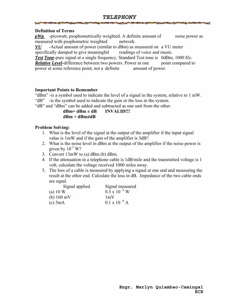
Definition of Terms pWp -picowatt, psophometrically weighted. A definite amount of noise power as measured with psophometric weighted network. VU -Actual amount of power (similar to dBm) as measured on a VU meter specifically damped to give meaningful readings of voice and music. Test Tone-pure signal at a single frequency. Standard Test tone is 0dBm, 1000 Hz. Relative Level-difference between two powers. Power at one point compared to power at some reference point, not a definite amount of power. Important Points to Remember “dBm” -is a symbol used to indicate the level of a signal in the system, relative to 1 mW. “dB” -is the symbol used to indicate the gain or the loss in the system. “dB” and “dBm” can be added and subtracted as one unit from the other.
dBm= dBm ± dB INVALID!!! dBm + dBm≠dB
Problem Solving: 1. What is the level of the signal at the output of the amplifier if the input signal
value is 1mW and if the gain of the amplifier is 3dB? 2. What is the noise level in dBm at the output of the amplifier if the noise power is
given by 10-3 W? 3. Convert 13mW to (a) dBm (b) dBrn. 4. If the attenuation in a telephone cable is 1dB/mile and the transmitted voltage is 1
volt, calculate the voltage received 1000 miles away. 5. The loss of a cable is measured by applying a signal at one end and measuring the
result at the other end. Calculate the loss in dB. Impedance of the two cable ends are equal.
Signal applied Signal measured (a) 10 W 0.3 x 10 -5 W (b) 160 mV 1mV (c) 3mA 0.1 x 10 -4 A
Engr. Marlyn Quiambao-Camingal ECE
TELEPHONY
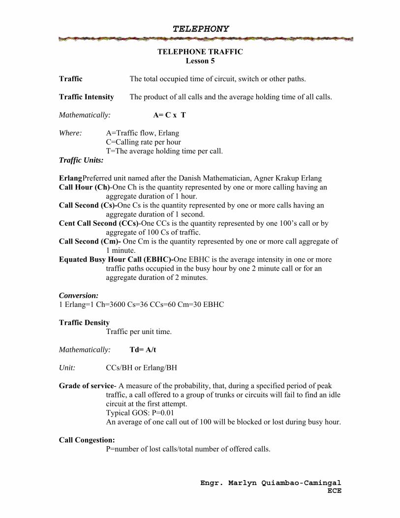
TELEPHONE TRAFFIC Lesson 5
Traffic The total occupied time of circuit, switch or other paths. Traffic Intensity The product of all calls and the average holding time of all calls. Mathematically: A= C x T Where: A=Traffic flow, Erlang C=Calling rate per hour T=The average holding time per call. Traffic Units: Erlang Preferred unit named after the Danish Mathematician, Agner Krakup Erlang Call Hour (Ch)-One Ch is the quantity represented by one or more calling having an
aggregate duration of 1 hour. Call Second (Cs)-One Cs is the quantity represented by one or more calls having an
aggregate duration of 1 second. Cent Call Second (CCs)-One CCs is the quantity represented by one 100’s call or by
aggregate of 100 Cs of traffic. Call Second (Cm)- One Cm is the quantity represented by one or more call aggregate of
1 minute. Equated Busy Hour Call (EBHC)-One EBHC is the average intensity in one or more
traffic paths occupied in the busy hour by one 2 minute call or for an aggregate duration of 2 minutes.
Conversion: 1 Erlang=1 Ch=3600 Cs=36 CCs=60 Cm=30 EBHC Traffic Density Traffic per unit time. Mathematically: Td= A/t Unit: CCs/BH or Erlang/BH Grade of service- A measure of the probability, that, during a specified period of peak
traffic, a call offered to a group of trunks or circuits will fail to find an idle circuit at the first attempt.
Typical GOS: P=0.01 An average of one call out of 100 will be blocked or lost during busy hour. Call Congestion: P=number of lost calls/total number of offered calls.
Engr. Marlyn Quiambao-Camingal ECE
TELEPHONY
Definition of Terms Attempt Any effort on the part of a traffic source to seize a circuit, switch or other
traffic channel, whether or not the attempt is successful. Call Any actual engagement or seizure of a circuit, switch or other traffic
channel. Calling Rate The number of calls per unit time. Calls per traffic source. Traffic Refers to the average of all user requests being serviced by the network. Traffic Rate The busy hour traffic density per traffic source. Density per traffic source. Lost calls or blocked calls-refers to calls that fail at the first trial. Busy Hour The continuous 60 minute period in a day during which the highest usage
occurs. Call Concentration-The ratio of the busy hour to the total day calls. It is the reciprocal
of length of day. Holding time Length of time during which call engages a traffic path or channel. Full availability-Each inlet has access to any outlet. Every free inlet is at all times able
to test every outlet. Limited Availability-When not all the free outlets in a switching system can be reached
by inlets. Carried Traffic The volume of traffic actually carried by the switch. Offered Traffic The volume of traffic offered by the switch. Occupation Time The total amount of time that a circuit is occupied.
Engr. Marlyn Quiambao-Camingal ECE
TELEPHONY
NUMBERING CONCEPT Lesson 6
Definition Terms: Subscriber Number – number to be dialed or called to reach a subscriber in the same local network or numbering area. Numbering Area – area which any two subscribers use the same dialing procedure to reach another subscriber in the telephone network. Trunk Prefix or Toll access Code – digit or combination of digits to be dialed by a calling subscriber in his own country but outside his own numbering area. Trunk Code or Area Code – digit or combination of digits (not including the trunk prefix) characterizing the called numbering area with a country. Country Code – combination of one to three digits characterizing the called country. Numbering Functions:
1. Call routing 2. Addressing of called and calling party 3. activates necessary apparatus for charging
If the numbering is 6 digits, it would start from 000000 to 999999. If the numbering is 7 digits, it would start from 0000000 to 9999999. Numbering Concepts:
1. Uniform Numbering – a scheme in which the length of the subscriber numbers are uniform inside a given numbering area.
2. Non-uniform Numbering – a scheme in which the subscriber numbers vary within a given numbering area.
International Telephone Number CCITT Recommendation E161 recommends that not more than 12 digits make up an international number. This excludes the international prefix that switches the call to the transmit exchange for international calls. 5 Elements: 1. International access code 2. Country Code 3. Area Code 4. Telephone Number
Engr. Marlyn Quiambao-Camingal ECE
TELEPHONY
Charging of call: 1. Flat Rate – fixed fee for unlimited number of calls. 2. Message – number calls is counted on a call meter.
Charging Long Distance Calls – dependent upon duration and distance. Two Ways of time Zone Metering
1. Bulk Billing (Multi-metering) – a call meter counts how many rate pulses are received during the call.
2. Toll Ticketing – accounts for individual calls; a computer or an operator notes which subscriber has called to whom, where and for how long.
Channel and Circuits: Types:
1. Simplex – one way communication 2. Half-duplex – two way communication but one at the time. 3. Full-duplex – simultaneously two way communication. 4. Full- full duplex – more than a half duplex but less than a full duplex.
Types:
1. Switched Circuit – a call is automatically switched through to its destination after dialing has been completed.
2. Leased (dedicated) Circuit – a permanent circuit for private use within a communication network, with the line directly between the two locations or routed through a serving central office.
Engr. Marlyn Quiambao-Camingal ECE
TELEPHONY
SIGNALING Lesson 7
Signaling *Refers to specific signals on the transmission line that are used for controlling the connection from the calling telephone to the called telephone and signals that are used to indicate the status of a call as it is being interconnected *provides a means for operating and supervising a telephone communication system *established connections, announces incoming calls and reports the fact that a line is busy Signaling Functions 1. Ringing Signals *used to operate a visible or audible alarm to alert someone of an incoming call 2. Supervisory Signals *used to convey information regarding switchboards conditions 3. Address Signals *used dialing or digital information which is necessary to establish the desire connections Subscriber Loop Signaling- 3 Methods 1. Wet-Dry *signaling information is indicated by the presence (wet) and the absence (dry) of a battery and ground condition on the line at the called end of the trunk. 2. Reverse Battery *loop signaling is accomplished by reversing the polarity of the battery on the line to indicate supervisory conditions 3. High-Low Method *by representing the on-hook and off-hook condition in terms of resistance values Other Signaling Method 1. E & M Signaling *employs 2 leads to connect the signaling equipment to trunk circuit, M lead transmit battery or ground to the distant end of the circuits and while incoming signals are received on the E lead as either a ground or open condition 2. Out Band Signaling *make use of one or more AC tones which lie within the passband of the transmission facility but just outside the voice band
Engr. Marlyn Quiambao-Camingal ECE
TELEPHONY
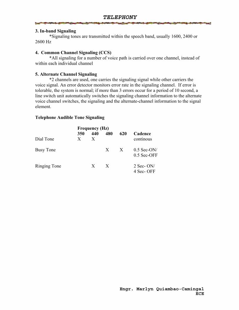
3. In-band Signaling *Signaling tones are transmitted within the speech band, usually 1600, 2400 or 2600 Hz 4. Common Channel Signaling (CCS) *All signaling for a number of voice path is carried over one channel, instead of within each individual channel 5. Alternate Channel Signaling *2 channels are used, one carries the signaling signal while other carriers the voice signal. An error detector monitors error rate in the signaling channel. If error is tolerable, the system is normal; if more than 3 errors occur for a period of 10 second, a line switch unit automatically switches the signaling channel information to the alternate voice channel switches, the signaling and the alternate-channel information to the signal element. Telephone Audible Tone Signaling Frequency (Hz) 350 440 480 620 Cadence Dial Tone X X continous Busy Tone X X 0.5 Sec-ON/ 0.5 Sec-OFF Ringing Tone X X 2 Sec- ON/ 4 Sec- OFF
Engr. Marlyn Quiambao-Camingal ECE
TELEPHONY
MULTIPLEXING FREQUENCY DIVISION MULTIPLEXING
Lesson 8
Multiplexing The process of transmitting two or more signals over the same communication channel. Multiplexer The device that accepts many inputs but will only give one output. Demultiplexer The device that accepts one input but separate the signals into many outputs.
Different Types of Multiplexing 1. FDM - Frequency Division Multiplexing 2. TDM - Time Division Multiplexing 3. WDM - Wavelength Division Multiplexing Frequency Division Multiplexing (FDM) • Analog scheme for multiplexing (input is analog and the output is still analog) • A method of multiplexing in which the total frequency spectrum available is divided
into channels, each which occupies a particular frequency range all of the time. • Introduce in the telephone networks in 1930s. • Applications: Frequency Modulation and Telemetry. Message Channel • Basic building block of the FDM hierarchy. • For voice transmission utilizing voice band frequencies. • Voice band frequency: 300-3400 Hz; 0-4000 Hz Basic Group • Next higher level in the FDM hierarchy. • Composed of 12 voice band channels • 60-108 kHz
Engr. Marlyn Quiambao-Camingal ECE
TELEPHONY
Basic Supergroup • The third level in the FDM hierarchy • Composed of 60 Voice channels. • From 312-552 kHz Basic Mastergroup • The fourth level in the FDM hierarchy • Composed of 6000 Voice band channels. Jumbogroup • The fifth level in the FDM hierarchy • Consists of 3600 Voice channels Superjumbogroup • The sixth in the FDM hierarchy • Consists of 10800 voice channels For CCITT Level No. of Voiceband channels Basic Group 12 Basic Supergroup 60 Basic Mastergroup 600 Jumbogroup 3600 Superjumbogroup 10800 For AT&T: Level No. of Voiceband Channels Group 12 Supergroup 60 Mastergroup 300 Supermastergroup 900
Engr. Marlyn Quiambao-Camingal ECE
TELEPHONY
TIME DIVISION MULTIPLEXING Lesson 9
Time Division Multiplexing A type of multiplexing wherein each signal can occupy the entire bandwidth of the channel but transmitted for only a brief period of time. It is used for both digital and analog signal inputs but the output is digital. Operation: To transmit multiple digital signals, the data to be transmitted is formatted into serial data words. One byte may be transmitted during the time interval assigned to a particular channel. Each timeslot might contain 1 byte from each channel. One channel transmit 8 bits and then halts while the next channel transmits 8 bits, and then the third channel as well transmits 8 bits and so on. This process is known as interleaving.
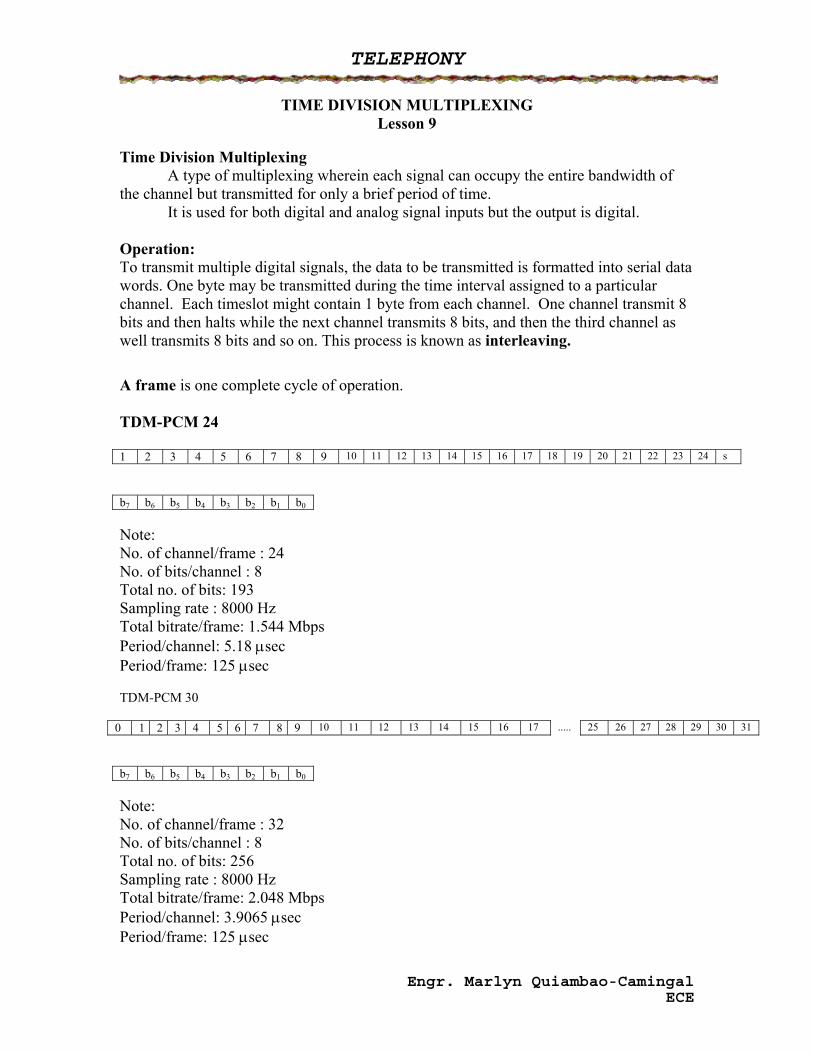
A frame is one complete cycle of operation. TDM-PCM 24 1 2 3 4 5 6 7 8 9 10 11 12 13 14 15 16 17 18 19 20 21 22 23 24 s b7 b6 b5 b4 b3 b2 b1 b0 Note: No. of channel/frame : 24 No. of bits/channel : 8 Total no. of bits: 193 Sampling rate : 8000 Hz Total bitrate/frame: 1.544 Mbps Period/channel: 5.18 μsec Period/frame: 125 μsec TDM-PCM 30
0 1 2 3 4 5 6 7 8 9 10 11 12 13 14 15 16 17 ..... 25 26 27 28 29 30 31 b7 b6 b5 b4 b3 b2 b1 b0 Note: No. of channel/frame : 32 No. of bits/channel : 8 Total no. of bits: 256 Sampling rate : 8000 Hz Total bitrate/frame: 2.048 Mbps Period/channel: 3.9065 μsec Period/frame: 125 μsec
Engr. Marlyn Quiambao-Camingal ECE
TELEPHONY
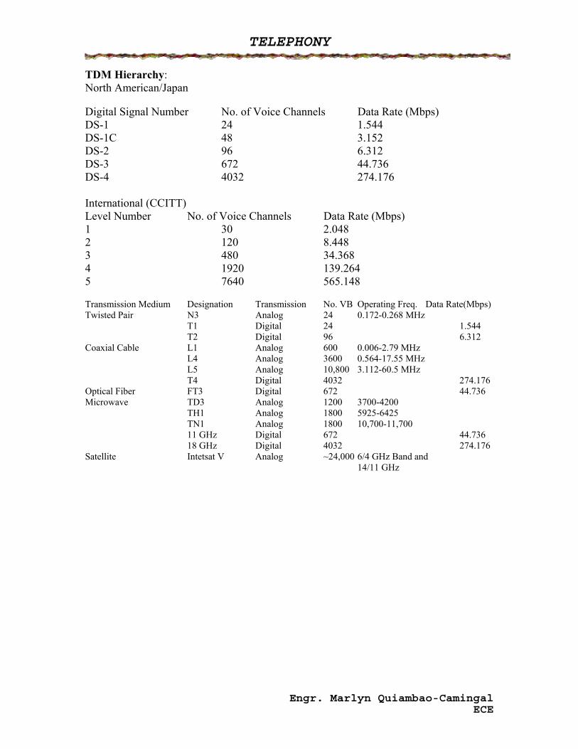
TDM Hierarchy: North American/Japan Digital Signal Number No. of Voice Channels Data Rate (Mbps) DS-1 24 1.544 DS-1C 48 3.152 DS-2 96 6.312 DS-3 672 44.736 DS-4 4032 274.176 International (CCITT) Level Number No. of Voice Channels Data Rate (Mbps) 1 30 2.048 2 120 8.448 3 480 34.368 4 1920 139.264 5 7640 565.148 Transmission Medium Designation Transmission No. VB Operating Freq. Data Rate(Mbps) Twisted Pair N3 Analog 24 0.172-0.268 MHz T1 Digital 24 1.544 T2 Digital 96 6.312 Coaxial Cable L1 Analog 600 0.006-2.79 MHz L4 Analog 3600 0.564-17.55 MHz L5 Analog 10,800 3.112-60.5 MHz T4 Digital 4032 274.176 Optical Fiber FT3 Digital 672 44.736 Microwave TD3 Analog 1200 3700-4200 TH1 Analog 1800 5925-6425 TN1 Analog 1800 10,700-11,700 11 GHz Digital 672 44.736 18 GHz Digital 4032 274.176 Satellite Intetsat V Analog ~24,000 6/4 GHz Band and 14/11 GHz
Engr. Marlyn Quiambao-Camingal ECE