Teleoperation with Force Feedback - ULisboa
76
Teleoperation with Force Feedback: Easing Unmanned Vehicles Operation in Unknown Scenarios André Casqueiro da Costa Ferreira Thesis to obtain the Master of Science Degree in Mechanical Engineering Supervisors: Prof. Alexandra Bento Moutinho Prof. Jorge Manuel Mateus Martins Examination Committee Chairperson: Prof. João Rogério Caldas Pinto Supervisor: Prof. Alexandra Bento Moutinho Member of the Committee: Prof. Pedro Vieira Gamboa November 2015
Transcript of Teleoperation with Force Feedback - ULisboa

Teleoperation with Force Feedback:Easing Unmanned Vehicles Operation in Unknown Scenarios
André Casqueiro da Costa Ferreira
Thesis to obtain the Master of Science Degree in
Mechanical Engineering
Supervisors: Prof. Alexandra Bento MoutinhoProf. Jorge Manuel Mateus Martins
Examination Committee
Chairperson: Prof. João Rogério Caldas PintoSupervisor: Prof. Alexandra Bento Moutinho
Member of the Committee: Prof. Pedro Vieira Gamboa
November 2015

ii

”I ... a universe of atoms, an atom in the universe.”
- Richard Feynman
iii

iv

Acknowledgments
I would like to express my sincere gratitude to my advisors Prof. Alexandra Moutinho and Prof. Jorge
Martins for their guidance and encouragement and, most of all, for accepting me in this great adventure.
I thank my fellow labmates, Afonso Ferreira, Antonio Campos, Diogo Ruivo, David Salvador, Nuno
Chaveiro and Renato Severiano, for the stimulating discussions, for always willing to give advice and be
guinea pigs for my experiments, and for all the fun we have had in these last months. I could not have
imagined having a better team. I am especially thankful to Rodrigo Coelho for the support in decoding
the laser scanner and Diogo Ruivo for providing the quadcopter model used in the development of a
simulator. Mr. Raposeiro and Eng. Camilo Christo for the time and technical support.
A thank you also extends to everyone who volunteered to participate in the experiments.
My old friend Jose Miguel Cerdeira for proofreading this thesis so quickly and offering suggestions
for its improvement.
Finally, a couple of personal notes. A heartfelt thank you to my family for their unconditional support
and for believing in me. Last but not the least, I would like to thank Joana Coelho, for always being there,
for her patience and for helping me maintain healthy levels of insanity.
v

vi

Resumo
Com o avanco da tecnologia, a presenca de veıculos nao-tripulados esta a aumentar e a utilizacao
destes em tarefas complexas que requerem interacao com o ambiente esta a crescer. No entanto, os
radios-comando tipicamente utilizados nao sao intuitivos e nao proporcionam uma percecao do pro-
cesso adequada.
Tendo isto em conta, o principal objetivo desta dissertacao e o desenvolvimento de um sistema
generico de teleoperacao haptica que possa ser aplicado em veıculos nao-tripulados aquaticos, ter-
restres e aereos. O sistema proposto inclui um novo feedback haptico baseado em vibracao e um novo
sistema anti-colisao que tem em consideracao tanto as indicacoes do operador como as limitacoes do
veıculo no ambiente que o rodeia. Como resultado de uma experiencia com um veıculo terrestre nao
tripulado, verificou-se uma diminuicao no tempo de prova e na carga total de trabalho do operador. O
feedback baseado em vibracao foi comparado com outros feedbacks hapticos numa experiencia em
que os utilizadores tiveram que identificar a direcao de um obstaculo virtual. O feedback proposto
superou os restantes tanto em tempo de resposta como em precisao.
Numa segunda fase, a eficiencia do sistema proposto foi avaliada atraves de uma experiencia em
que os utilizadores operaram um quadricoptero num ambiente virtual. Os resultados obtidos confirmam
o esperado aumento de transparencia durante a operacao, assim como um aumento de conforto do
operador e seguranca do veıculo com um tempo de prova reduzido.
Palavras-chave: Teleoperacao, Controlo Haptico, Feedback Haptico, Sistema Anti Colisao,
Veıculos Nao Tripulados
vii

viii

Abstract
With the emerging technologies, the presence of unmanned vehicles is increasing and their relevance in
complex tasks that require interaction with the environment is growing. However, typical radio controllers
are not intuitive and do not provide the user with an appropriate situation awareness.
Taking this into account, the main goal of this thesis is the development of a generic haptic teleoper-
ation scheme with increased transparency for unmanned water, ground or aerial vehicles. The proposed
scheme includes a novel haptic feedback based on vibration and a new anti-collision method that takes
into account both vehicle and environment constraints. User experiments with an unmanned ground
vehicle using the anti-collision method show a reduction in both task completion time and human op-
erator workload. The vibration feedback was compared with other haptic feedbacks in an experiment
where users had to identify the direction of a single obstacle. The existing feedback solutions were
outperformed both in preciseness and celerity.
In a second experiment subjects evaluated the effectiveness of the vibration feedback in a 3D sce-
nario, where a quadcopter was maneuvered through a maze in a simulator. Results confirm the ex-
pected increase in obstacle awareness and task easiness. Furthermore, the use of a haptic feedback
also increased the operator’s comfort while executing the task, it decreased the number of collisions and
reduced the task completion time.
Keywords: Teleoperation, Haptic Control, Force Feedback, Obstacle Avoidance, Unmanned
Vehicle
ix

x

Contents
Acknowledgments . . . . . . . . . . . . . . . . . . . . . . . . . . . . . . . . . . . . . . . . . . . v
Resumo . . . . . . . . . . . . . . . . . . . . . . . . . . . . . . . . . . . . . . . . . . . . . . . . . vii
Abstract . . . . . . . . . . . . . . . . . . . . . . . . . . . . . . . . . . . . . . . . . . . . . . . . . ix
List of Tables . . . . . . . . . . . . . . . . . . . . . . . . . . . . . . . . . . . . . . . . . . . . . . xiii
List of Figures . . . . . . . . . . . . . . . . . . . . . . . . . . . . . . . . . . . . . . . . . . . . . xv
Nomenclature . . . . . . . . . . . . . . . . . . . . . . . . . . . . . . . . . . . . . . . . . . . . . . xvii
1 Introduction 1
1.1 Motivation . . . . . . . . . . . . . . . . . . . . . . . . . . . . . . . . . . . . . . . . . . . . . 1
1.2 Problem definition . . . . . . . . . . . . . . . . . . . . . . . . . . . . . . . . . . . . . . . . 3
1.3 Related work . . . . . . . . . . . . . . . . . . . . . . . . . . . . . . . . . . . . . . . . . . . 4
1.4 Objectives and Contributions . . . . . . . . . . . . . . . . . . . . . . . . . . . . . . . . . . 5
1.5 Structure of the Dissertation . . . . . . . . . . . . . . . . . . . . . . . . . . . . . . . . . . . 5
2 Methods 7
2.1 Haptic interfaces . . . . . . . . . . . . . . . . . . . . . . . . . . . . . . . . . . . . . . . . . 7
2.1.1 Implementation . . . . . . . . . . . . . . . . . . . . . . . . . . . . . . . . . . . . . . 8
2.2 Master-Slave Mapping . . . . . . . . . . . . . . . . . . . . . . . . . . . . . . . . . . . . . . 10
2.3 Obstacles Perception . . . . . . . . . . . . . . . . . . . . . . . . . . . . . . . . . . . . . . 12
2.3.1 State of the Art . . . . . . . . . . . . . . . . . . . . . . . . . . . . . . . . . . . . . . 12
2.3.2 Newly Developed Methods . . . . . . . . . . . . . . . . . . . . . . . . . . . . . . . 14
2.4 Anti-Collision System . . . . . . . . . . . . . . . . . . . . . . . . . . . . . . . . . . . . . . 16
2.4.1 State of the Art . . . . . . . . . . . . . . . . . . . . . . . . . . . . . . . . . . . . . . 16
2.4.2 Newly Developed Methods . . . . . . . . . . . . . . . . . . . . . . . . . . . . . . . 17
2.5 Haptic Feedback . . . . . . . . . . . . . . . . . . . . . . . . . . . . . . . . . . . . . . . . . 23
2.5.1 State of the Art . . . . . . . . . . . . . . . . . . . . . . . . . . . . . . . . . . . . . . 23
2.5.2 Vibration Feedback . . . . . . . . . . . . . . . . . . . . . . . . . . . . . . . . . . . . 24
2.5.3 Implementation . . . . . . . . . . . . . . . . . . . . . . . . . . . . . . . . . . . . . . 26
2.5.4 Methods Comparison Results . . . . . . . . . . . . . . . . . . . . . . . . . . . . . . 28
3 2D Experiment 31
3.1 Platform OMNI-ANT . . . . . . . . . . . . . . . . . . . . . . . . . . . . . . . . . . . . . . . 31
xi

3.2 Goals and Objectives . . . . . . . . . . . . . . . . . . . . . . . . . . . . . . . . . . . . . . 32
3.3 Procedure . . . . . . . . . . . . . . . . . . . . . . . . . . . . . . . . . . . . . . . . . . . . . 32
3.4 User Interface . . . . . . . . . . . . . . . . . . . . . . . . . . . . . . . . . . . . . . . . . . . 33
3.5 Subjects and Instructions . . . . . . . . . . . . . . . . . . . . . . . . . . . . . . . . . . . . 34
3.6 Maze . . . . . . . . . . . . . . . . . . . . . . . . . . . . . . . . . . . . . . . . . . . . . . . 34
3.7 Results . . . . . . . . . . . . . . . . . . . . . . . . . . . . . . . . . . . . . . . . . . . . . . 35
3.8 Discussion . . . . . . . . . . . . . . . . . . . . . . . . . . . . . . . . . . . . . . . . . . . . 37
4 3D Experiment 39
4.1 Quadcopter Model . . . . . . . . . . . . . . . . . . . . . . . . . . . . . . . . . . . . . . . . 39
4.2 Goals and Objectives . . . . . . . . . . . . . . . . . . . . . . . . . . . . . . . . . . . . . . 40
4.3 Procedure . . . . . . . . . . . . . . . . . . . . . . . . . . . . . . . . . . . . . . . . . . . . . 41
4.4 User Interface . . . . . . . . . . . . . . . . . . . . . . . . . . . . . . . . . . . . . . . . . . . 42
4.5 Subjects and Instructions . . . . . . . . . . . . . . . . . . . . . . . . . . . . . . . . . . . . 42
4.6 Maze . . . . . . . . . . . . . . . . . . . . . . . . . . . . . . . . . . . . . . . . . . . . . . . 43
4.7 Results . . . . . . . . . . . . . . . . . . . . . . . . . . . . . . . . . . . . . . . . . . . . . . 45
4.8 Discussion . . . . . . . . . . . . . . . . . . . . . . . . . . . . . . . . . . . . . . . . . . . . 46
5 Conclusions 49
5.1 Future Work . . . . . . . . . . . . . . . . . . . . . . . . . . . . . . . . . . . . . . . . . . . . 50
Bibliography 53
xii
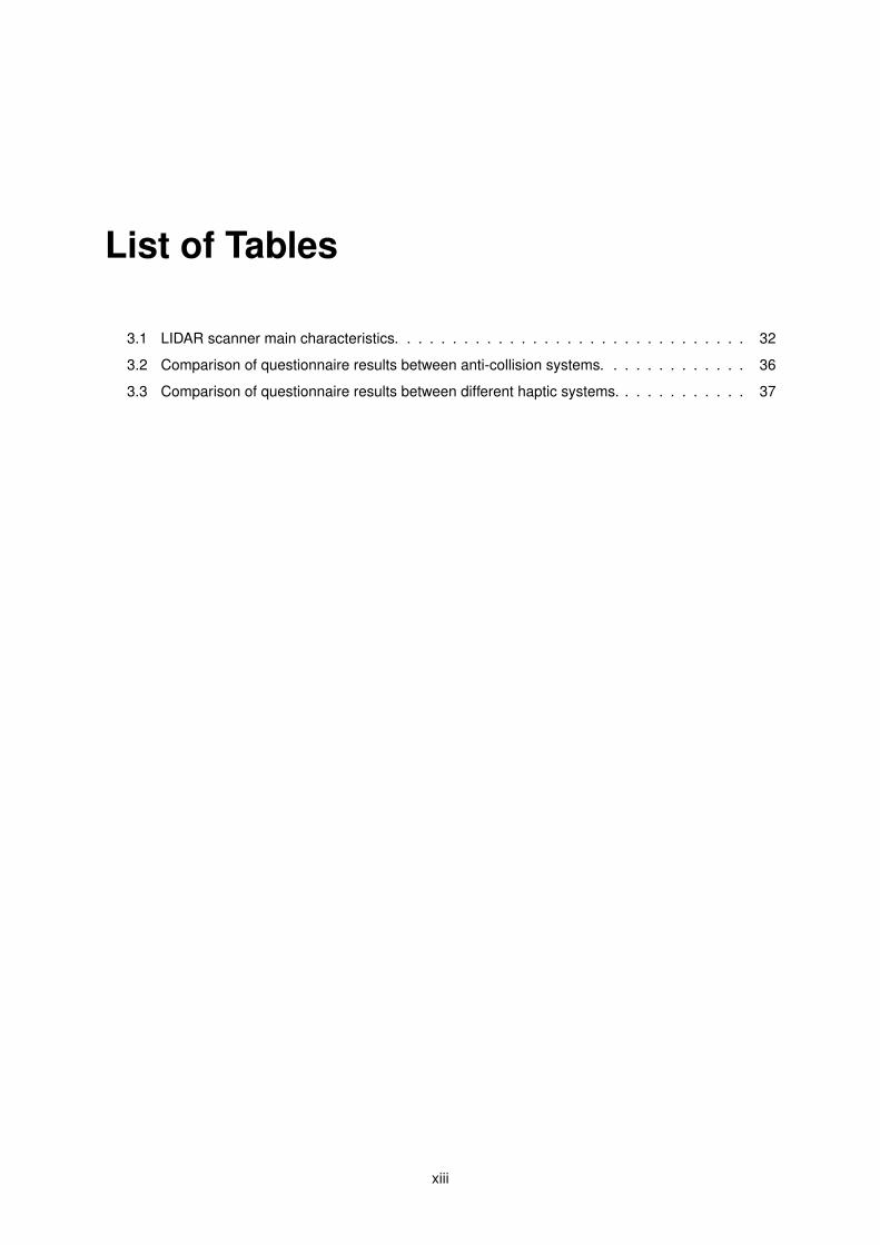
List of Tables
3.1 LIDAR scanner main characteristics. . . . . . . . . . . . . . . . . . . . . . . . . . . . . . . 32
3.2 Comparison of questionnaire results between anti-collision systems. . . . . . . . . . . . . 36
3.3 Comparison of questionnaire results between different haptic systems. . . . . . . . . . . . 37
xiii

xiv

List of Figures
1.1 Generic achitecture of bilateral teleoperation . . . . . . . . . . . . . . . . . . . . . . . . . 3
2.1 Haptic interfaces. . . . . . . . . . . . . . . . . . . . . . . . . . . . . . . . . . . . . . . . . . 7
2.2 Local Force diagram. . . . . . . . . . . . . . . . . . . . . . . . . . . . . . . . . . . . . . . . 9
2.3 BRF contour plot . . . . . . . . . . . . . . . . . . . . . . . . . . . . . . . . . . . . . . . . . 13
2.4 PRF contour plot . . . . . . . . . . . . . . . . . . . . . . . . . . . . . . . . . . . . . . . . . 14
2.5 Examples of resulting obstacle direction vector for different scenarios. . . . . . . . . . . . 15
2.6 Anti-collision methods diagram. . . . . . . . . . . . . . . . . . . . . . . . . . . . . . . . . . 17
2.7 Relation between velocity and distance . . . . . . . . . . . . . . . . . . . . . . . . . . . . 17
2.8 Wall approach example . . . . . . . . . . . . . . . . . . . . . . . . . . . . . . . . . . . . . 18
2.9 Corrected velocity for the vehicle approaching a wall from south, using avoidance system. 19
2.10 Corrected velocity for the vehicle approaching a wall from south, using deconfliction system. 20
2.11 Initial velocity space. . . . . . . . . . . . . . . . . . . . . . . . . . . . . . . . . . . . . . . . 21
2.12 Resulting allowed velocity space for an obstacle approaching the vehicle from north-east. 21
2.13 Avoidance scenarios. . . . . . . . . . . . . . . . . . . . . . . . . . . . . . . . . . . . . . . 22
2.14 Deconfliction scenarios. . . . . . . . . . . . . . . . . . . . . . . . . . . . . . . . . . . . . . 22
2.15 Force and Stiffness feedback representation . . . . . . . . . . . . . . . . . . . . . . . . . 24
2.16 Vibration feedback example. . . . . . . . . . . . . . . . . . . . . . . . . . . . . . . . . . . . 25
2.17 Vibration feedback period and amplitude along distance to obstacle. . . . . . . . . . . . . 25
2.18 Mater device width response evaluation. . . . . . . . . . . . . . . . . . . . . . . . . . . . . 27
2.19 Mater device frequency response evaluation. . . . . . . . . . . . . . . . . . . . . . . . . . 27
2.20 Haptic experiment visual interface . . . . . . . . . . . . . . . . . . . . . . . . . . . . . . . 28
2.21 Main results of haptic experiment for each type of feedback: force, stiffness and vibration
feedback. . . . . . . . . . . . . . . . . . . . . . . . . . . . . . . . . . . . . . . . . . . . . . 29
3.1 OMNI-ANT . . . . . . . . . . . . . . . . . . . . . . . . . . . . . . . . . . . . . . . . . . . . 31
3.2 Master system. . . . . . . . . . . . . . . . . . . . . . . . . . . . . . . . . . . . . . . . . . . 33
3.3 Experiment visual interface. . . . . . . . . . . . . . . . . . . . . . . . . . . . . . . . . . . . 34
3.4 Top view of the maze used for experiments. . . . . . . . . . . . . . . . . . . . . . . . . . . 35
3.5 Comparison results between avoidance system (AS) and deconfliction system (DS). . . . 36
3.6 Comparison results between no haptic feedback, force, stiffness and vibration feedbacks. 37
xv

3.7 Feedback type preference. . . . . . . . . . . . . . . . . . . . . . . . . . . . . . . . . . . . 38
4.1 Examples of user visual interface. . . . . . . . . . . . . . . . . . . . . . . . . . . . . . . . 42
4.2 Simulation maze 1. . . . . . . . . . . . . . . . . . . . . . . . . . . . . . . . . . . . . . . . . 43
4.3 Simulation maze 2. . . . . . . . . . . . . . . . . . . . . . . . . . . . . . . . . . . . . . . . . 44
4.4 Simulation maze 3. . . . . . . . . . . . . . . . . . . . . . . . . . . . . . . . . . . . . . . . . 44
4.5 Results comparison between different cases. . . . . . . . . . . . . . . . . . . . . . . . . . 45
4.6 Questionnaire results comparison for different cases. . . . . . . . . . . . . . . . . . . . . . 46
xvi

Nomenclature
Acronyms
AFF Artificial Force Field
BRF Basic Risk Field
DOF Degree of Freedom
GPF Generalized Potential Field
LIDAR Light Detection And Ranging
PRF Parametric Risk Field
PTZ pan-Tilt-Zoom
UAV Unmanned Aerial Vehicle
UGV Unmanned Ground Vehicle
VTOL Vertical Take-Off and Landing
Greek symbols
θobs Principal direction of obstacles
(φ, θ, ψ) Euler angles (roll, pitch and yaw)
(θ, φ, r) Spherical coordinates (azimuth, elevation and radial distance)
Roman symbols
Cm Master device damping coefficient
fa Applied force
fl Local force
Km Master device spring coefficient
q0 Master end effector center position
qm Master end effector position
xvii
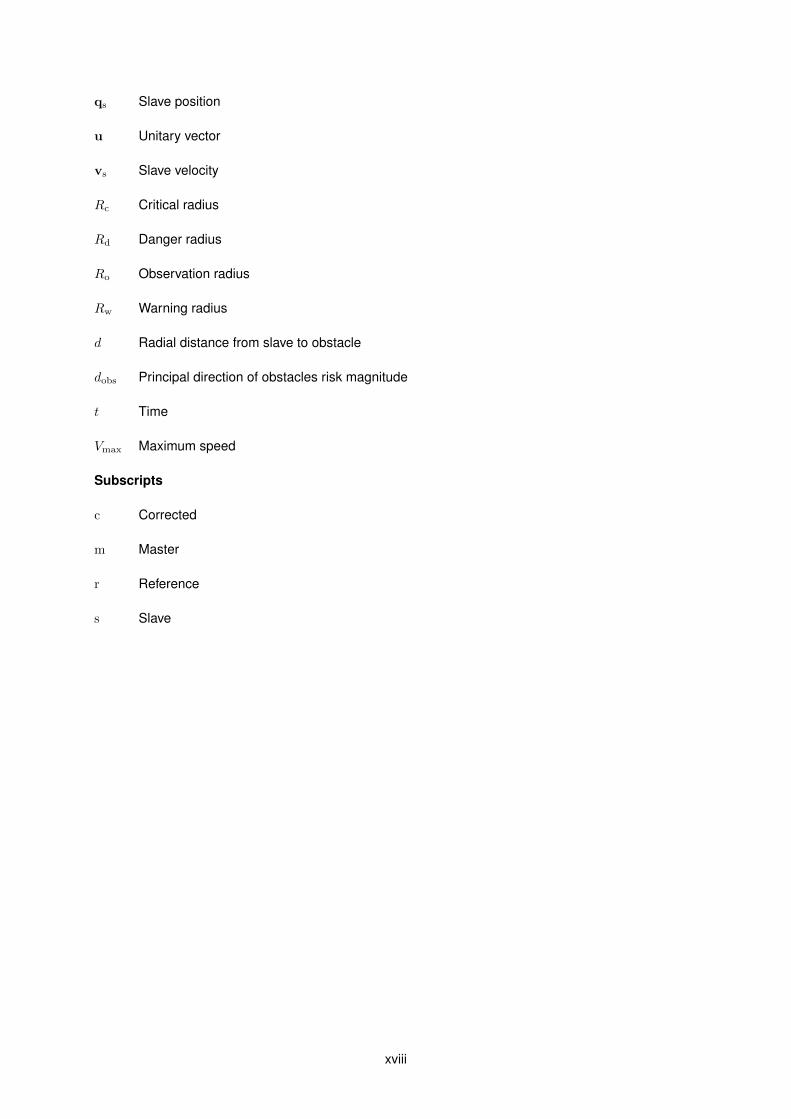
qs Slave position
u Unitary vector
vs Slave velocity
Rc Critical radius
Rd Danger radius
Ro Observation radius
Rw Warning radius
d Radial distance from slave to obstacle
dobs Principal direction of obstacles risk magnitude
t Time
Vmax Maximum speed
Subscripts
c Corrected
m Master
r Reference
s Slave
xviii

Chapter 1
Introduction
With the increasing development of technology, robots are becoming more and more present in our lives.
In particular, unmanned vehicles are substituting the presence of humans in operations that imply difficult
access and health risks. However, typical radio controllers do not provide the necessary precision
and easiness for these operations. In this thesis, we present an intuitive scheme for haptic bilateral
teleoperation of unmanned vehicles with obstacle avoidance system.
1.1 Motivation
Since the beginning of robotics studies, teleoperation has been one of the main issues of investiga-
tion. Teleoperation or telerobotics refers to the operation of a machine at a distance, implying a barrier
between the operator and the environment. This barrier, besides distance, may also be imposed by
hazardous environment or a large difference in scaling. Whereas this separation can be small enough
to have the human operator and the robot occupying the same room.
The first case of a teleoperated system dates back to the 1940s by Raymond C. Goertz [1]. Using
electrical and mechanical components, he created manipulators for humans to handle radioactive ma-
terial from behind shielded walls. However, without a feeling of touch, these manipulators were slow
and awkward to operate. In order to overcome this constraint, it became clear that the operator should
be able to feel the environment through the robot. This concept known as bilaterality, refers to the
case where, during teleoperation, information flows in both ways. Not only does the operator control
the robot, as the robot transmits information related to its environment. Using sensors, the robot per-
ceives its surroundings and may then reflect back to the operator the states of the task being performed.
This information is perceived by the operator through his visual, tactile and hearing senses, either using
images of the operation, force feedback or other signals.
Nowadays, classical bilateral teleoperated manipulators are mostly used in the field of surgery. In
2001 teleoperation was used in surgery for the first time when a surgeon in New York (USA) operated
a patient in Strasbourg (France) [2]. Meanwhile, in order to overcome the human desire to explore
unknown and dangerous environments, mobile robots were developed. In opposition to classical ma-
1

nipulators, mobile robots do not have a limited workspace, they are not physically bounded to a certain
position of space. In particular, teleoperation was implemented in the control of unmanned ground vehi-
cles (UGV). Initially they were used mainly for image extraction, reconnaissance, surveillance and target
acquisition [3, 4]. However, with the industrial growth they became an important presence in field appli-
cations, such as crop harvesting, land demining and indoor transportation [5]. In spite of their extended
maneuverability, UGVs are restricted to the surface on which they move.
With the beginning of flight history, the importance of aerial robots was accentuated due to the
number of causalities associated with early flights. Since then, aerial robotics have accompanied flight
evolution. During World War II, the first fixed-wing teleoperated unmanned aerial vehicles (UAVs), com-
monly named drones, appeared. Their initial purpose was for anti-aircraft training and posterior for
surveillance, reconnaissance and other war affairs [6, 7].
During the turn of the twenty-first century, the increase of processors power and the appearing of
more reliable and cheaper sensors with smaller dimensions has caused a growing interest in UAVs. The
first commercial quadrotors appeared and their usage took a shift to more everyday life activities. A
quadrotor or quadcopter, is an aircraft propelled by four rotors. While typical fixed-wing aerial robots,
such as airplanes, require runways to gain speed for lift-off, quadrotors are capable of vertical take-
off and landing (VTOL), as well as hovering in constant position. For this reason, these vehicles are
preferable for indoor operations and when space is a constraint. They also present a few advantages
over helicopters. First, the use of four rotors allows for a relatively smaller diameter, also meaning less
kinetic energy. Second, quadrotors are easier to control and provide a less aggressive flight, which
allows an increased maneuverability in indoor operations. Finally, quadrotors are usually more crash-
resistant and less expensive to maintain and repair.
Recently, the quadrotors presence is growing stronger, being used for personal use and for activities
that require interaction with the environment. Some of the most relevant applications of quadrotors are:
inspection of structures with difficult or dangerous access [8, 9] (for example, inspection of high voltage
power cables [10]), search and rescue missions [11], journalism [12], investigation [13, 14] and for film
making. The use of quadrotors in these applications prevents the endangering of human lives while
reducing costs. However, for these activities the human operator needs to easily navigate the vehicle
while focusing on its mission. Typical controllers (RC transmiter) are not intuitive, beginners are usually
confused by its mechanisms and take a long time to master it. Husak [15] verified that using a haptic
controller allows a more intuitive flight and also provides the user a higher level of abstraction. From
the greek haptesthai, meaning ”to contact” or ”to touch”, haptic refers to the use of tactile sensation
in human interaction with computers. Furthermore, in Husak experiments, beginners using a haptic
controller were able to complete an obstacle course with reduced number of collisions.
Besides the physical controller, teleoperation is usually accompanied by a video transmission from
the vehicle on-board camera. However, seeing only what is in front of the unmanned vehicle, the human
controller is not able to perceive its surrounding. Some solutions may include the use of more than
one camera or a PTZ (pan-tilt-zoom) camera. However, these solutions require an extra weight on the
unmanned vehicle, being an issue for aerial vehicles for example. Aside from not being able to precisely
2

recognize proximity to visible obstacles, there is no awareness of obstacles in other directions.
Having this in mind, in this thesis we complement the process of teleoperation by using the sense
of touch. In other words, we implement and evaluate a teleoperation scheme based on force feedback.
Through on-board sensors, the unmanned vehicle is able to detect obstacles in its surroundings. Be-
sides preventing any collision, due to vehicle’s anti-collision system, the vehicle control system transmits
the obstacles information to the master system. The master system then uses actuators to haptically
inform the operator of the presence of obstacles in the vehicle’s proximity.
Until now we have seen a brief summary of the origins and evolution of teleoperation. As we will see
in the next section, the distance between the operator and the vehicle raises various challenges in the
use of teleoperated vehicles. In the following, the organization of a teleoperation system is explained,
along with the main difficulties and goals of teleoperation.
1.2 Problem definition
A generic unmanned vehicle bilateral teleoperation system can be represented by the diagram in Fig.1.1.
The user interacts with the teleoperation system through the master device. The master device is con-
sidered the set of devices used to receive and transmit information to the operator, for example: RC
transmitters, joysticks, computer mouse, keyboards, screens, sound columns and others. In haptics, the
master device consists of at least a haptic controller capable of transmitting forces and motions between
the user and the master controller. The master controller is responsible for mapping the user inputs to
the respective motion of the slave, as well as calculating the appropriate force feedback (e.g., inversely
proportional to the distance to existing obstacles).
The slave controller is composed of a high-level controller and a low-level controller. The high-
level controller trades information with the master controller through the communication channel and,
if necessary, adapts the master output according to the slave state and surrounding, e.g., to prevent
a collision. The low-level controller is in charge of regulating the dynamics of the slave (usually aerial
vehicles are unstable and require a control system to maintain flight). The slave device refers to the
physical vehicle that is being operated. This schema can be applied to any aerial, ground or underwater
vehicle.
Human operator
Master Device
Master controller
Communication channel
Slave controller
Slave device
Environment
Human operator
Master Device
Master controller
Communication channel
Slave controller
Slave device
Environment
Teleoperation system
Figure 1.1: Generic architecture of bilateral teleoperation
3

The main challenges in classical robotic teleoperation are caused by network induced imperfections
such as time delays and packet losses, which are primary sources of instability and lack of transparency.
Besides these, the haptic teleoperation of unmanned vehicles adds some additional challenges. First,
there is a dissimilarity between the master and the slave workspaces. While the master is bounded by
the device mechanism, the slave vehicle has usually no limits to its movement. Second, there is no
direct interaction between the vehicle and the environment, i.e., the haptic feedback does not originate
from physical contact with the environment, but from artificial fields built around obstacles. Third, the
states of the vehicle are difficult to measure and most of the times they have to be estimated.
In teleoperation there are two main goals, stability and transparency [16]. The teleoperation is stable
if the stability of the closed-loop system is established irrespective of the behavior of the operator or the
environment. The stability of the system is usually verified through the passivity of the system. Assuming
that the environment and human operator are passive, and if the teleoperation passivity is verified, then
we can guarantee passivity of the closed-loop [17].
Slawinski et al. [18] introduce the concept of absolute transparency, which measures the trans-
parency of bilateral teleoperation through three criteria: local, remote and instantaneous transparency.
The first two quantify the similarity between the state of the slave and how it is felt by the operator, and
between the state of operator and how it is seen by the slave, respectively. The third criterion measures
the delay in communication and how fast the operator feels the slave and vice-versa.
These goals are generally conflicting. However, satisfying these requirements assures the function-
ality of the teleoperation system.
1.3 Related work
Before 2009, most of the works regarding the use of haptic methods for teleoperation of single UAVs has
been made by Lam et al. [19–21] and Brandt and Colton [22]. These first works focus mainly in the use
of haptic feedback to assist the user and provide a collision free teleoperation. Moreover, in [23], Lam et
al. reduce the effects of communication time delays through introduction of wave variables. Mahony et
al. [24] investigated the use of optical flow to provide force feedback to an operator’s joystick to facilitate
collision free teleoperation.
More recent works include a series of studies by Mersha et al. [25–28]. In these studies, an approach
based on network theory and port-Hamiltonian systems is used to formulate the proposed teleoperation
scheme and evaluate its passivity. In [29], Stramigioli et al. introduce the concept of virtual slave which
is later extended by Mersha et al. [30] to a multidimensional and underactuated case. Other relevant
works include the application of an admittance framework for teleoperation of UAVs by Mahony and
Hou [31–34].
All aforementioned works share a similar conclusion: the teleoperation of unmanned vehicles can be
improved through the use of a haptic feedback transmitting information regarding the state of the vehicle
and its surroundings to the remote operator.
4

1.4 Objectives and Contributions
The main goal of this work is the development of a haptic teleoperation scheme that enhances the
performance of the human operator during complex tasks that require interaction of unmanned vehicles
with the environment. The developed scheme should help operators to perform their teleoperation task
safely and efficiently, while reducing the workload.
With respect to the stated goals, the main specific contributions of this thesis are summarized as
follows:
1. Design of a new collision avoidance method (section 2.4.2), and performance comparison with
existing solutions. The solution comprehends two steps: i) the determination of the obstacles
principal direction vector; and ii) the agreement of the operator requested velocity vector with the
previously obtained obstacles vector. Two systems may be applied for this agreement, avoidance
or deconfliction systems. The former, slows down the vehicle to avoid collision. The latter, adapts
the vehicle velocity so it is both safe and similar to the desired velocity. This method is implemented
directly in the vehicle system, providing a safe operation even if communication with the master
fails.
2. Design of a novel type of force feedback based on vibration (section 2.5.2). By taking advantage
of the sensibility to vibration, users should get a better perception of the vehicle surroundings
from the vibration produced by the haptic controller. This new solution increases the teleoperation
transparency and safety level while maintaining a low task workload.
3. Validation and verification of the feasibility and efficiency of the proposed control architecture
through experimental tests in a 2D scenario (Chapter 3). The proposed vibration feedback is com-
pared with other haptic feedbacks in an experiment where subjects had to teleoperate a ground
omnidirectional vehicle through an unseen and unknown maze. Furthermore, the proposed anti-
collision methods are evaluated during this experiment.
4. Design of a 3D simulator where a quadcopter could be virtually teleoperated through different
indoor scenarios (Chapter 4). This interface was afterwards used to evaluate the effectiveness of
the proposed vibration feedback in a 3D environment. In this second experiment, subjects had to
teleoperate a virtual quadcopter over three different 3D mazes.
Part of the work described in items 1 - 3 is accepted to be presented at ROBOT’2015: Second Iberian
Robotics Conference, being published in Springer’s Advances in Advances in Intelligent Systems and
Computing Series [35].
1.5 Structure of the Dissertation
The organization of this dissertation is briefly described as follows. In Chapter 2 the main components
of a generic haptic teleoperation scheme are divided into five sections, for each section the state of the
5

art is presented and if applicable it is followed up by the developed theory. Furthermore for each section,
implementation issues are discussed.
A first experiment where subjects had to teleoperate a UGV through an unseen maze is fully de-
scribed in Chapter 3. Afterwards, a second experiment using the quadcopter simulator is presented in
Chapter 4.
Finally, in Chapter 5, this work main conclusions are presented along with recommendations for
future investigation opportunities.
6

Chapter 2
Methods
In this chapter, the main theoretical aspects of teleoperation are discussed. The most common tech-
niques used in teleoperation of unmanned robots are presented along with newly developed techniques
which, afterwards, are compared.
This chapter is organized as follows. Section 2.1 presents the different possible interfaces between
the user and the haptic master device. Section 2.2 studies different mapping techniques for teleopera-
tion, that is, how the signal from the master device can be mapped as a reference for the slave vehicle.
Afterwards, section 2.3 focuses on different obstacle perception methods, in which the vehicle surround-
ings is evaluated and represented by variables that can later be used for the following two sections.
Section 2.4 uses the previously obtained parameters to adapt the vehicle reference and prevent any col-
lision with the environment. Finally, in section 2.5, the different methods that can be used to haptically
inform the user of the vehicle surroundings (haptic feedbacks) are discussed.
In each of these sections, a brief overview of the state of the art is presented and, when applicable,
followed up by the developed theory. Afterwards, implementation issues are discussed and, if necessary,
validated. In the final section, an experiment where different haptic feedbacks were compared is also
presented.
2.1 Haptic interfaces
In haptics, there are two types of interface between the user and the master device: impedance and
admittance. Impedance refers to the case where the user applies a displacement to the master device,
and the device responds with a force (Fig. 2.1(a)). On the other side, in admittance control, the user
applies a force to the master device, and the device responds with a proper displacement (Fig. 2.1(b)).
User Master Slave
d
f
vr
fr
(a) Impedance interface.
User Master Slave
f
d
vr
dr
(b) Admittance interface.
Figure 2.1: Haptic interfaces.
7

Impedance is the most common configuration in haptic devices [27, 29, 36]. Typical impedance con-
figured devices are low inertia, low friction and backdrivable devices that can measure the position of the
end-effector and exert force and/or torque to the user [37]. The most commonly used impedance devices
in haptic teleoperation are joysticks with force feedback, the Novint Falcon, the Geomagic Phantom, and
the Force Dimension Omega series.
Admittance devices are generally heavy, stiff and not easily backdrivable [37]. These devices are
capable of measuring the input force applied to its end effector, and respond with an appropriate dis-
placement. Most of the work in teleoperation with unmanned aerial vehicles using admittance interface
was done by Hou and Mahony [31–34, 38]. In [38], Schill et al. applied the first admittance framework
for hovering vehicles. The results obtained are promising, however the device used (Novint Falcon)
does not provide the necessary rigidity for admittance control, causing a faulty feedback perception.
Using a modified Novint Falcon, in 2013, Hou controled a quadrotor by scaling the force applied on the
master device to the speed of the vehicle. The speed of the vehicle was then mapped to the position
of the master end effector [31]. Afterwards, Hou and Mahony realized a series of studies using admit-
tance interfaces [32–34]. During these studies, two admittance devices were developed, including an
admittance trackball capable of force feedback. In these works, the authors defend that an admittance
interface provides the pilot with a better feel of the vehicle dynamics.
In [39], Soares compares the use of impedance and admittance interfaces in the teleoperation of
aerial vehicles. Results show that during free flight, the admittance framework provides the user with
better haptic cues regarding the state of the vehicle. However, in the presence of obstacles and when
environment interactivity is desired, the use of an impedance interface is preferred. The main difference
verified in these interfaces is their bandwidths. Admittance acts as a low pass filter, which is adequate for
slave pose tracking. On the other hand, impedance acts as a high pass filter which is more appropriate
for fast changing cues, e.g., a force feedback regarding the presence of an obstacle.
2.1.1 Implementation
This thesis presents a teleoperation scheme that allows the control of unmanned vehicles in obstacle-
laden environments. Accordingly to the results previously referred, an impedance interface should allow
a more appropriate control for this type of scenarios. Furthermore, the master device used in this work,
the Novint Falcon, has already been ruled out for for admittance control. As mentioned before, Hou and
Mahony [31, 38] have already applied an admittance framework with a Novint Falcon and arrived at the
conclusion that this device is not appropriate for admittance control. For these reasons, we opted to use
an impedance interface for the developed teleoperation scheme.
One of the functions of the master controller is to ensure a stable control of the master device end
effector. Typically, in impedance, when released, the end effector of the master device should move
to the center of operation, which corresponds to a zero velocity reference for the slave. While some
devices achieve this through physical springs and dampers (for example, most type of joysticks), haptic
manipulators require this control to be implemented through a virtual spring and damper system.
8

The implemented spring and damper system block diagram is represented in Fig. 2.2. The user
applies a force, fa, on the end effector, which causes the end effector to move. The end effector dis-
placement, qm, is then used to calculate the spring and damper force, which we denominate as local
force, fl. During teleoperation, the user does not control the applied force, but rather the position of the
end effector, which is eventually used to map the slave reference. Consequently, during teleoperation,
instead of forcing a displacement of the end effector, the local force should simply increase the user
perception of the actual position of the end effector. As a reminder, if an admittance interface was used,
the force applied by the user would be the system input, and the position of the end effector would be
solely controlled by the master controller.
Master Device end effector
Local Force Renderer
fa
fl
qm +
+
Figure 2.2: Local Force diagram.
The local force, fl, can be represented by the following expression:
fl = −Km(qm − qo)−Cmqm (2.1)
where Km and Cm correspond to spring and damper matrix coefficients, vectors qm and qm are the
position and velocity of the master device, respectively and qo is the zero position of the master device.
The local force parameters (Km and Cm) have to be tuned taking into account the following aspects:
teleoperation transparency, teleoperation comfort, and when released, stability of the manipulator. Re-
garding the spring coefficient, Km, as it increases, the workspace center position and frame axes be-
come more accentuated, therefore, increasing the user perception of the workspace. For example, if the
user is pushing the manipulator forward and desires to move slightly to the side, a well-defined spring
force would allow the user to easily understand if the position of the manipulator is coincident with the
respective axis or located near to the axis. On the other hand, if Km is too low, the user might be unable
to perceive it, and consequently loose understanding of the workspace. However, a high spring coeffi-
cient also increases the required force to move the manipulator, resulting in an increased task workload
as well as a reduction of the process comfort. Furthermore, a strong spring force may override other
forces, such as a force feedback.
A solution to improve the spring coefficient tuning is to limit the spring force through saturation. Limit-
ing the spring force allows to use a higher spring coefficient while avoiding its disadvantages. The values
used as boundaries for the spring force should take into account the previously mentioned objectives as
well as the haptic device being used and its characteristics.
The damping coefficient, Cm, has an important role in diminishing the oscillation of the manipulator
when released. However, if this value is too high, the user will experience a feeling of drag in the end ef-
9

fector that will contribute to increase the sensitive overload of the user, hence reducing the transparency
of the teleoperation. In order to increase the teleoperation comfort and transparency, the manipulator is
allowed to have small oscillations when released, as long as its stability is assured.
2.2 Master-Slave Mapping
In order to overcome the difference in the workspaces of the master and the slave devices, a car driving
metaphor [40] (rate control) is usually used [27, 41, 42]. In opposition to pose control, where the pose
of the master is mapped to the pose of the slave, in rate control, the pose of the master is mapped to
the velocity reference of the slave. This method allows the human operator to manipulate an unbounded
robot through a bounded device.
When using the impedance framework, the mapping of the master device position is described as
qsr = λq qm (2.2)
for pose control and as
vsr = λv qm (2.3)
for rate control, where λq and λv are scaling matrices and qsr and vsr represent the desired reference
position and velocity for the slave, respectively. It is common in impedance control to feedback to the
master device the error between the desired position/velocity and the real slave position/velocity. This
feedback allows the user to feel the dynamics of the teleoperated vehicle.
When an admittance framework is used, the mapping is described as:
qsr = λq fa (2.4)
vsr = λv fa (2.5)
respectively for pose and rate control, and where fa represents the force applied by the user on the
master haptic device. The feedback is done through a displacement of the master device, that represents
the actual movement of the slave for pose mode. For rate mode, the master control moves the master
device to a position that represents the real velocity of the slave.
Some authors consider that rate control does not provide the user with the precision required for
potential application areas such as inspection and object manipulation. To address this issue, Mersha
et al. present a kinetic scrolling-based position mapping [25]. This algorithm is inspired by the kinetic
scrolling of smart phones. The mapping strategy has two modes, direct and sliding mode. In direct
mode, the master’s position is mapped to the slave’s reference position. In sliding mode, the vehicle
slides accordingly to the speed of the vehicle at the moment of switch. To realize the two modes, a
virtual mass, mv, is coupled with the master device through a spring-damper, during direct mode. In
sliding mode, the virtual mass is decoupled from the master and a viscous damper is introduced. The
10

position of this virtual mass is then scaled to a reference position of the slave.
When covering fairly large areas, the scrolling-based technique requires a constant switching be-
tween the two modes. For this reason, the same authors present another solution, a switching-based
mapping [26, 28]. The switching-based mapping combines the rate and the pose based control strate-
gies to maneuver the unmanned vehicle, guaranteeing control in unbounded environments and in-
creased precision. In this solution, the operator is allowed to switch the current mode (pose or rate)
by pressing a button on the haptic device. However, switching at a nonzero position of the master re-
quires alternative interpretations. According to the interpretations, two submodes are identified for each
mode, namely the normal and reset submodes.
When switching from rate to pose mode at a nonzero master position, two situations may occur. The
current position of the slave is interpreted as an offset between the master’s zero position and the slave.
This corresponds to resetting the center of the workspace to its original position. The second case is to
define the current position of the master as the new center of operation. The two cases represent the
reset and normal submodes, respectively.
Following the same reasoning, when switching from pose to rate mode at a nonzero master position,
the current position of the master can be interpreted as either a nonzero velocity reference or a zero
velocity reference. These two situations are referred to as reset and normal submodes, respectively.
In both pose and rate modes, the normal submode results in a smoother transition. However, the
normal submode may result in an asymmetrical mapping of the master’s position. The submode should
be chosen accordingly to the situation for a better performance.
Omari et al. [43] also introduced a new mapping capable of handling the issue of precision versus
unlimited workspace. In this method, based on the bubble technique [44], a virtual sphere is created
around the zero position of the haptic device. Inside this sphere, a pose mapping is applied, i.e., the
position of the haptic device is mapped to the position of the slave. Outside the sphere, rate mode is
applied.
When the master device is inside the sphere, the mapping directly relates the position of the master
with the slave position, around the center of operation. In this case, the center of operation remains
constant. When the operator moves outside the position sphere, the center of operation starts moving in
the direction of the movement. The speed at which the center of operation moves, and consequently the
slave, is determined by the position of the end effector. When the operator reenters the position sphere,
the center of operation stops moving and the slave can be operated around this new position.
The authors referred above defend that rate mode may not provide the necessary precision for teleop-
eration of unnamed vehicles. However, initial teleoperation tests using an UAV support that the precision
obtained using a rate control is satisfactory and suitable for this thesis objectives. Consequently, in this
thesis the master-slave mapping is implemented using a rate control. The remaining mapping methods
are presented as alternatives for future work.
11

2.3 Obstacles Perception
2.3.1 State of the Art
The first step to generate a haptic feedback is to examine the slave surroundings and calculate a suitable
intensity and direction for the force feedback. The most common method is to use artificial force fields
(AFF), also referred to as potential fields. Originally, AFFs purpose is to map obstacles as repulsive
forces acting on the vehicle and targets as attractive forces. Summing the repulsive forces of each ob-
stacle with the attractive force of the target destination, results in a final vector containing the magnitude
and direction for a collision free path towards the destination.
In teleoperation, the human operator decides where to go in real time. Consequently, there are no
target destinations or attractive forces. However, the repulsive forces can be mapped to feedback forces
that will assist the operator during the teleoperation process.
The artificial force field proposed in [45] was based on the distance between a robot arm and an
object. However, since the algorithm only takes into account the distance to objects, repulsive forces
would always be present, even when moving away from the obstacle. Applying this method in haptic
teleoperation would require the operator to constantly counteract the repulsive forces, increasing the
operation workload.
In [46], Krogh presents the generalized potential field (GPF), which takes into account the vehicle
deceleration limits and the speed in relation to an obstacle. The GPF is calculated as the inverse of the
difference between the maximum (tmax) and minimum avoidance time (tmin). The minimum avoidance
time is the time required to bring the speed towards the obstacle to zero, using the vehicle maximum
deceleration amax. The maximum avoidance time is defined as the time required to brake the vehicle
just before collision, using a constant deceleration (smaller than the maximum deceleration).
The GPF still has some limitations if used for haptic feedback. As the difference between tmax
and tmin tends to zero, the potential field tends to infinity which would be impractical due to hardware
limitations. Furthermore, the GPF only maps obstacles in the direction of movement, which could result
in collision with lateral obstacles.
In [21], Lam extends the concept of GPF by including a saturation of the potential field and using
distance as stop criteria instead of time. The modified potential field is referred to as basic risk field
(BRF). Instead of using the difference between the maximum and minimum avoidance times, a reserve
avoidance distance is defined as the difference between the braking distance, d, when decelerating with
less than the maximum deceleration and the minimum distance, dstop, required to brake at maximum
deceleration. Figure 2.3 shows an example of the resulting GPF in two situations, vehicle is static and
moving forward.
The BRF is normalized between zero and one, respectively for minimum risk and maximum risk
situation. This field has the advantage of calculating force for small negative velocities at small distances
from obstacles. The main disadvantage appointed by the author [21] is the rather large size of the field
for high velocities, which may result in a difficult control through narrow passages.
In [21], Lam also presents another potential field that allows more control over the size and shape
12

Figure 2.3: Two-dimensional contour plots of the BRF, adapted from [21]. (a) vs = 0 m/s. (b) vs = 4 m/s.
of the risk field: the parametric risk field (PRF). The PRF consists of two boundaries: a maximum risk
boundary which limits the critical region with a risk of one, and an outside boundary from which the risk
becomes zero. The critical zone is defined by a vehicle protection radius plus a braking distance, dstop,
similar to the one used in BRF. The outer boundary is defined by a distance, dmin, from the critical region
and a complementary distance which depends on the direction of motion and compensates the operator
reaction time. Between boundaries, the risk value is defined by the ratio between the distance to the
critical zone and the distance between boundaries in that section.
The contour of the PRF is exemplified in figure 2.4 for the vehicle in a static position and in a moving
forward case. As the figure shows, this AFF produces a more restricted contour in comparison to BRF.
After obtaining an AFF, a final avoidance vector has to be calculated. Assuming that obstacles are
detected by angular sensors, the AFF can be used to calculate the risk magnitude for each sensor radial
line. Afterwards, the individual risk vectors obtained have to be integrated into a final vector. There are
several ways to join the individual vectors: sum, mean and max/min, i.e. the sum of the largest positive
and negative risk vectors. In all cases, the final vector is limited to one.
In [32], Hou proposes a new approach for obstacle perception, the dynamic kinesthetic boundary
(DKB). It is constructed as a boundary for the vehicles velocity based on the distance to the obstacle.
This boundary takes into account two parameters, a safety distance and a threshold distance. Safety
distance is used to limit how close the vehicle will approach obstacles while the threshold distance
defines at which distance the field starts acting. Besides using the value obtained to send a signal to
the user, this value is also used to limit the velocity of the vehicle. In case of perfect velocity tracking,
the dynamic kinesthetic boundary ensures that the vehicle never collides with the environment.
13

Figure 2.4: Two-dimensional contour plots of the PRF, adapted from [21]. (a) vs = 0 m/s. (b) vs = 4 m/s.
2.3.2 Newly Developed Methods
This thesis presents two newly developed obstacle perception methods. The first method consists of
obtaining a principal obstacle vector that represents the major direction and proximity of obstacles sur-
roundings the vehicle. The second method, developed by Ruivo [35], uses the information regarding the
slave environment to define the allowed velocity space, similarly to the DKB.
In the first method, we first need to calculate the principal direction of obstacles surrounding the ve-
hicle. Consider spherical coordinates in the body fixed frame of the slave represented by radial distance
r, azimuth θ and elevation φ. Let d (θ, φ, t) denote the radial distance from the origin of the body fixed
frame of the slave to the first obstacle along direction (θ,φ) at time t. For each point inside an observation
zone, defined by the observation radius Ro, consider a unitary vector pointing from the obstacle to the
vehicle frame origin, described by:
u (θ, φ, t) = − cos θ cosφ i− sin θ cosφ j− sinφk (2.6)
The principal direction of obstacles, θobs, is computed by taking a weighted average of all unitary
vectors within the observation zone (d (θ, φ, t) < Ro):
θobs(t) =
θd(t)
‖θd(t)‖, if ‖θd(t)‖ 6= 0.
0, otherwise.(2.7)
θd(t) =∑θ,φ
u(θ, φ, t) f(Ro − d(θ, φ, t)) (2.8)
14
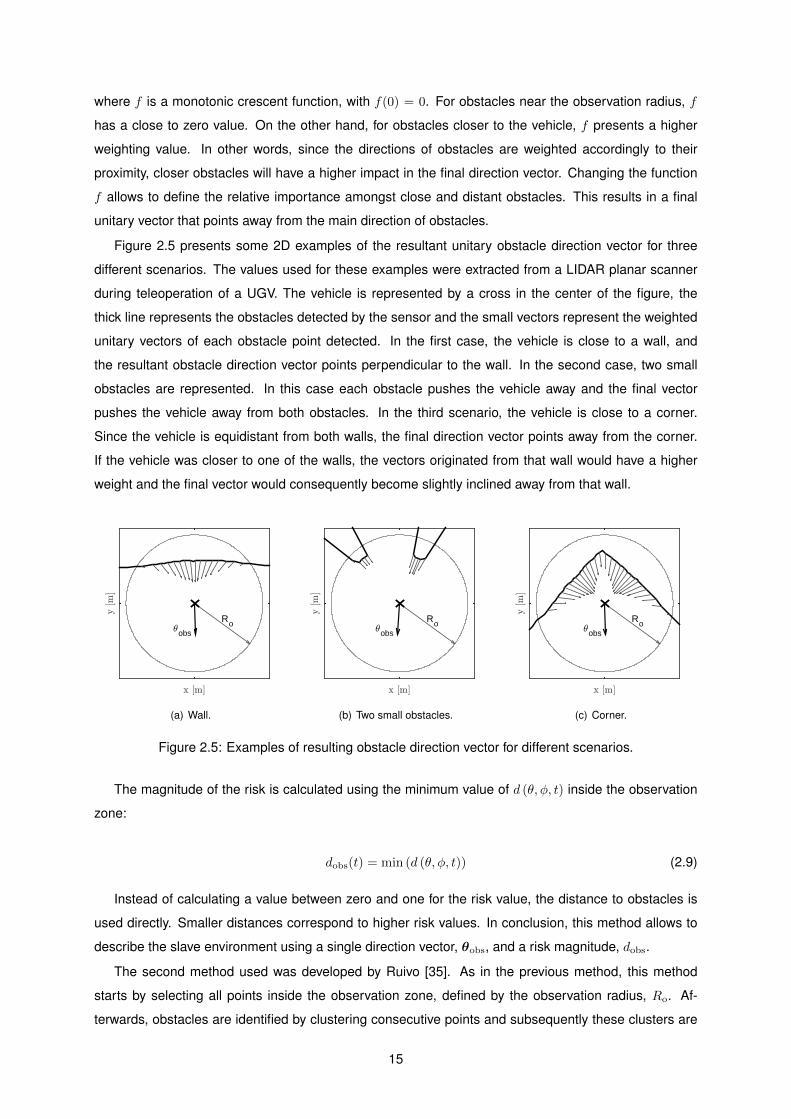
where f is a monotonic crescent function, with f(0) = 0. For obstacles near the observation radius, f
has a close to zero value. On the other hand, for obstacles closer to the vehicle, f presents a higher
weighting value. In other words, since the directions of obstacles are weighted accordingly to their
proximity, closer obstacles will have a higher impact in the final direction vector. Changing the function
f allows to define the relative importance amongst close and distant obstacles. This results in a final
unitary vector that points away from the main direction of obstacles.
Figure 2.5 presents some 2D examples of the resultant unitary obstacle direction vector for three
different scenarios. The values used for these examples were extracted from a LIDAR planar scanner
during teleoperation of a UGV. The vehicle is represented by a cross in the center of the figure, the
thick line represents the obstacles detected by the sensor and the small vectors represent the weighted
unitary vectors of each obstacle point detected. In the first case, the vehicle is close to a wall, and
the resultant obstacle direction vector points perpendicular to the wall. In the second case, two small
obstacles are represented. In this case each obstacle pushes the vehicle away and the final vector
pushes the vehicle away from both obstacles. In the third scenario, the vehicle is close to a corner.
Since the vehicle is equidistant from both walls, the final direction vector points away from the corner.
If the vehicle was closer to one of the walls, the vectors originated from that wall would have a higher
weight and the final vector would consequently become slightly inclined away from that wall.
x [m]
y[m
]
Ro3obs
(a) Wall.
x [m]
y[m
]
Ro3obs
(b) Two small obstacles.
x [m]
y[m
]
Ro3obs
(c) Corner.
Figure 2.5: Examples of resulting obstacle direction vector for different scenarios.
The magnitude of the risk is calculated using the minimum value of d (θ, φ, t) inside the observation
zone:
dobs(t) = min (d (θ, φ, t)) (2.9)
Instead of calculating a value between zero and one for the risk value, the distance to obstacles is
used directly. Smaller distances correspond to higher risk values. In conclusion, this method allows to
describe the slave environment using a single direction vector, θobs, and a risk magnitude, dobs.
The second method used was developed by Ruivo [35]. As in the previous method, this method
starts by selecting all points inside the observation zone, defined by the observation radius, Ro. Af-
terwards, obstacles are identified by clustering consecutive points and subsequently these clusters are
15

simplified through a line simplification method. This results in each obstacle being defined by a set of
line segments. The final step is to calculate the closest point to the vehicle frame for each line segment.
Unlike the first method that resulted in a single vector, this method results in a group of feature vectors,
each defined by a distance and a direction. The number of resulting feature vectors depends on the
slave surroundings.
The main difference between the obstacle perception methods present in the bibliography and the
proposed methods is how the risk magnitude is calculated. Typically, the risk magnitude is obtained as
a relation between the current speed of the vehicle and the distance to obstacles (e.g. time to impact
and reserve avoidance distance). This procedure makes sense since high risk situations will correspond
to stronger feedbacks that will force the user to take countermeasures. However, when an autonomous
anti-collision system is implemented, this notion of risk loses its significance, since the anti-collision
system will stop the vehicle from colliding. On the other hand, the transparency of the process becomes
more relevant. For example, using a time to impact procedure, the resulting magnitude of the feedback
when moving the slave against an obstacle can be the same for both a large distance at high slave
speed, against a small distance at low speed. This causes the user to be unable to understand how close
the slave is to the obstacle. By calculating the risk magnitude solely on the distance to obstacles, the
proposed methods provide a more transparent teleoperation, while the anti-collision method guarantees
the process safety.
2.4 Anti-Collision System
Besides sending a haptic feedback to the user, the results of the methods presented in the previous sec-
tion can also be used for collision avoidance. In this case the risk vector may be adapted in accordance
to the collision avoidance system.
2.4.1 State of the Art
Most authors consider obstacle avoidance in teleoperation through the haptic device [21, 41, 47]. After
evaluating the slave surroundings, a corresponding feedback is sent to the master device, which in turn,
either directly or through the user reaction, causes a displacement of the end effector and consequently
guides the vehicle away from the obstacle.
In [32], Hou uses the dynamic kinesthetic boundary to simultaneously drive a signal for haptic feed-
back and to limit the velocity of the slave along the direction to the obstacle. As the vehicle approaches
an obstacle, the maximum velocity in that direction is reduced until it becomes null at a predetermined
safety distance from the obstacle. Similarly, in [48], a distance to obstacles function is used to modify the
reference velocity of the slave. However, in this case, repulsive velocities are calculated for all obstacles
and summed into a final repulsive velocity which is added to the slave reference velocity.
16

2.4.2 Newly Developed Methods
Two obstacle perception methods were applied for collision avoidance. The first method (main direction
method) uses the main direction and distance to obstacles, the second method (clipping method) uses
the obstacles feature vectors. For both methods, two systems were implemented, an avoidance system
and a deconfliction system. The former ignores the user’s command if it means getting closer than
allowed to an obstacle. The latter, besides preventing the vehicle from getting too close to an obstacle,
also adapts the vehicle velocity to be as similar as possible to the velocity reference. Figure 2.6 shows
a diagram of the anti-collision methods used.
Main direction
method
Avoidance
Deconfliction
Avoidance
Deconfliction
Clipping
method
Anti-collision
methods
Figure 2.6: Anti-collision methods diagram.
Although some authors use the haptic feedback to ensure a collision free teleoperation, the delays
present in communication between master and slave will affect the efficiency of the anti-collision system.
Furthermore, unsuccessful communication between master and slave may jeopardize the system safety
and result in collision. By implementing the anti-collision directly in the vehicle, we can assure that even
if communications are cut down, the vehicle will not hit an obstacle.
Distance to Obstacle [m]
0 Rc
Rd
Rw
Veh
icle
vel
oci
ty[m
/s]
-Vmax
0
Vmax Critical
ZoneDangerZone
WarningZone Safe Zone
Figure 2.7: Relation between velocity and distance to obstacle.
The approach used for anti-collision is represented in figure 2.7 for the one dimension case. Accord-
ing to the distance to obstacle, the speed reference towards the obstacle is limited. For an obstacle
in the safe zone, the speed towards the obstacle is only restricted by the maximum physically allowed
speed of the vehicle, Vmax. Below the warning radius, Rw, the speed is reduced until it becomes zero
at distance Rd, the danger radius. If the obstacle enters the danger zone, the maximum allowed speed
becomes negative, i.e. the vehicle is forced to move away from the obstacle. In normal conditions the
obstacle should never enter the critical zone. If it does happen then the vehicle moves away from the
obstacle at maximum speed. The critical zone is defined by the critical radius, Rc, which consists of the
17

vehicle radius plus an extra safety distance. The critical radius also guarantees safety during rotational
movements, even for non-circular vehicles.
Proceeding to a real case scenario with two or three dimensions, the problem becomes more com-
plex. For example, when pushing the slave against a wall, the anti-collision system should limit the
speed towards the wall to avoid a crash. However, the user should still be able to freely move the vehicle
parallel to the wall. In figure 2.8, the two approaches used (avoidance and deconfliction system) are
represented for the wall example. With the avoidance system, if there is any obstacle along the direc-
tion of the velocity reference, then the vehicle velocity is reduced according to the relations previously
shown. This results in the vehicle being slowed down until it stops at a radial distance Rd from the
obstacle. On the other hand, if the deconfliction system is used, then only the component of the velocity
towards the obstacle is limited and any tangential component is kept unchanged. For the wall example,
the deconfliction system results in an intuitive smooth displacement along the wall.
x position
y po
sitio
n
Rd
avoidancedeconflictionwallspeed reference
Figure 2.8: Vehicle approaching wall with constant velocity reference. Difference between avoidancesystem and deconfliction system.
The first anti-collision method is implemented through comparison of the velocity reference vector
with the main obstacle vector. To verify if the desired velocity reference has a component directed
towards an obstacle, we just need to verify if the dot product between the velocity reference vector and
the main obstacle vector is negative:
θobs(t) · vsr(t) < 0 (2.10)
If this condition is verified, then the vehicle reference velocity has to be adjusted accordingly to the
distance to obstacle. The distance to obstacle, or risk value, is evaluated using the variable dobs. For
the plain avoidance system, if the obstacle is inside the warning zone (Rd < dobs < Rw) then the speed
reference is proportionally reduced as the distance to Rd reduces:
vsc = vsr
dobs −Rd
Rw −Rd(2.11)
where vsc represents the slave corrected reference velocity. If the obstacle gets closer than Rd, then the
user command is ignored and the vehicle is pushed away from the obstacle with the same direction as
18

θobs. The new velocity reference is given by:
vsc = Vmax θobsdobs −Rc
Rd −Rc(2.12)
Inside the critical zone, the vehicle is always pushed away from the obstacle at maximum speed:
vsc = Vmax θobs (2.13)
Remember that θobs is an unitary vector that points away from obstacles.
Figure 2.9 presents examples of the resulting corrected velocity in the presence of a wall at different
distances. In the first case, the wall is inside the warning zone so the corrected velocity corresponds
to a proportional reduction of the original reference velocity. In the second case, at distance equal to
the danger radius, the corrected velocity is null. Finally, in the third case, inside the danger zone, the
reference velocity is ignored and the corrected velocity gets the direction of θobs.
x [m]
y [m
] vref
3obs
vc
(a) Wall inside the Warning Zone.
x [m]
y [m
]
vref
3obs
(b) Wall in the Danger Radius.
x [m]
y [m
]
vref
3obs
vc
(c) Wall inside the Danger Zone.
Figure 2.9: Corrected velocity, vc, for the vehicle approaching a wall from south, using avoidance system.The reference velocity is constant for the three cases.
For the deconfliction system, these equations become slightly different. For an obstacle inside the
warning zone, only the component of the reference velocity towards the obstacle is reduced. This
component is obtained using the dot product:
vsc = vsr − θobs (θobs · vsr)Rw − dobsRw −Rd
(2.14)
Notice that the term θobs (θobs · vsr) represents the component of the reference velocity towards the
obstacle. The termRw − dobsRw −Rd
varies from zero to one as the distance to obstacle gets closer to Rd. So
as the vehicle gets closer to an obstacle, the component of the velocity towards the obstacle is gradually
reduced from its velocity reference. If the obstacle enters the danger zone, then the component of the
velocity towards the obstacle is completely removed and starts increasing in the opposite direction:
vsc = vsr − θobs (θobs · vsr) + θobs VmaxRd − dobsRd −Rc
(2.15)
If the obstacle gets closer than Rc, the vehicle is repelled from the obstacle at maximum speed:
19

vsc = vsr − θobs (θobs · vsr) + θobs Vmax (2.16)
The examples previously presented using the avoidance system are now presented in Fig. 2.9 for
the deconfliction system. In the first case, inside the warning zone, the velocity reference is once again
reduced, however, when using the deconfliction method, only the vertical component of the velocity
(which is parallel to θobs) is reduced. In the second case, at distance equal to the danger radius,
the vertical component becomes null, being left only the horizontal component, which is parallel to
the wall. In the final case, inside the danger zone, the vertical component of the velocity reference
changes direction while the horizontal component is unchanged. It can easily be seen that when the
avoidance system was used, the vehicle was forced to stop when directed at the wall. However, using
the deconfliction system, the vehicle maintains a velocity parallel to the wall, while the velocity towards
the wall is adapted to maintain a safety distance.
x [m]
y [m
] vref
3obs
vc
(a) Wall inside the Warning Zone.
x [m]
y [m
]
vref
3obs
vc
(b) Wall in the Danger Radius.
x [m]
y [m
]vref
3obs
vc
(c) Wall inside the Danger Zone.
Figure 2.10: Corrected velocity, vc, for the vehicle approaching a wall from south, using deconflictionsystem. The reference velocity is constant for the three cases.
In conclusion, the developed avoidance anti-collision system can be described by the following set
of equations:
vsc =
vsr
dobs −Rd
Rw −Rd, if Rd ≤ dobs < Rw and (θobs · vsr) < 0.
Vmax θobsdobs −Rc
Rd −Rc, if Rc ≤ dobs < Rd.
Vmax θobs, if dobs < Rc.
vsr , otherwise.
(2.17)
while the deconfliction anti-collision system is described by the equations:
20

vsc =
vsr − θobs (θobs · vsr)Rw − dobsRw −Rd
, if Rd ≤ dobs < Rw and (θobs · vsr) < 0.
vsr − θobs (θobs · vsr) + θobs VmaxRd − dobsRd −Rc
, if Rc ≤ dobs < Rd and (θobs · vsr) < 0.
vsr − θobs (θobs · vsr) + θobs Vmax, if dobs < Rc and (θobs · vsr) < 0.
vsr , otherwise.
(2.18)
The second anti-collision approach used in this thesis was developed by Ruivo [35]. This method
starts by drawing the allowed velocity space of the slave. For example, for a planar omnidirectional
vehicle, the initial allowed velocity space can be described by a circle of radius Vmax, the maximum
speed allowed for the vehicle (Fig. 2.11).
vx [m/s]
-Vmax 0 V
max
v y[m/s]
-Vmax
0
Vmax
Figure 2.11: Initial velocity space.
Afterwards, the feature vectors obtained during the obstacle detection process are used to clip the
allowed velocity space. The clipping is done in accordance to the distance to obstacle relation previously
presented (Fig 2.7). Figure 2.12 shows an example of the clipping done by a single object approaching
the vehicle from north-east.
vx [m/s]
-Vmax 0 V
max
v y[m/s]
-Vmax
0
Vmax
(a) Obstacle inside the Warning Zone.
vx [m/s]
-Vmax 0 V
max
v y[m/s]
-Vmax
0
Vmax
(b) Obstacle in the Danger Radius.
vx [m/s]
-Vmax 0 V
max
v y[m/s]
-Vmax
0
Vmax
(c) Obstacle inside the Danger Zone.
Figure 2.12: Resulting allowed velocity space for an obstacle approaching the vehicle from north-east.
Finally, after doing the clipping for all obstacle feature vectors, the reference velocity is adapted
accordingly to the new allowed space velocity. Figure 2.13 represents the different possible scenarios
21

for the avoidance system. If the slave reference velocity belongs to the allowed space velocity, then it
is unchanged. If the reference velocity is outside the allowed space, two situations may occur. If the
desired velocity crosses the allowed velocity space, its magnitude is reduced until it is inside the allowed
space (2.13(b)). If it does not cross the allowed space, it is ignored and substituted by the closest to the
origin point (no velocity) that belongs to the allowed space (2.13(c)).
vx [m/s]
-Vmax 0 V
max
v y[m/s]
-Vmax
0
Vmax
(a) Desired velocity inside allowed veloc-ity space.
vx [m/s]
-Vmax 0 V
max
v y[m/s]
-Vmax
0
Vmax
(b) Desired velocity crossing allowed al-lowed velocity space.
vx [m/s]
-Vmax 0 V
max
v y[m/s]
-Vmax
0
Vmax
(c) Desired velocity outside allowed ve-locity space.
Figure 2.13: Avoidance scenarios. Circle defines velocity space. Shaded area: allowed velocity space.Black arrow: desired velocity. Red arrow: corrected velocity.
The same scenarios shown for the avoidance system are presented in figure 2.14 for the decon-
fliction system. The deconfliction system always takes into account the desired velocity. If the slave
reference velocity belongs to the allowed space velocity, then, as in the avoidance case, it is unchanged.
If the reference velocity is outside the velocity allowed space, then it is always substituted by the clos-
est velocity that belongs to the allowed space. This method allows a collision-free teleoperation while
maintaining a displacement as similar to the desired as possible.
vx [m/s]
-Vmax 0 V
max
v y[m/s]
-Vmax
0
Vmax
(a) Desired velocity inside allowed veloc-ity space.
vx [m/s]
-Vmax 0 V
max
v y[m/s]
-Vmax
0
Vmax
(b) Desired velocity crossing allowed al-lowed velocity space.
vx [m/s]
-Vmax 0 V
max
v y[m/s]
-Vmax
0
Vmax
(c) Desired velocity outside allowed ve-locity space.
Figure 2.14: Deconfliction scenarios. Circle defines velovity space. Shaded area: allowed velocityspace. Black arrow: desired velocity. Red arrow: corrected velocity.
Although providing similar results, in the presence of multiple obstacles the clipping method provides
a more robust solution for both avoidance and deconfliction systems. However, the signal used for the
main direction method can simultaneously be used as a haptic feedback reference. Furthermore, the
22

main direction method requires less processing time. The method used should be chosen according to
the available processing time. If, for example due to sensors low sampling rates or low communication
rates, the anti-collision system is not the limiting factor, then the clipping method should be used. Oth-
erwise, if the anti-collision system is limiting the cycle rate, then the main direction method should be
used.
2.5 Haptic Feedback
In the preceding sections we saw some of the most recent methods used to analyze the vehicle sur-
roundings and provide an obstacle related single final vector of risk. Besides being used for anti-collision
systems, this vector can also be used to hapticly transmit relevant information to the user. In this section
we present some solutions regarding how this trade of information can be made. Furthermore, a novel
haptic feedback based on vibration is also presented.
2.5.1 State of the Art
Assuming we have a vector containing information concerning the vehicles surrounding obstacles, e.g.
the final risk vector obtained using AFFs, we now want to use the master device to transmit a simple
signal to the user hand so that the user becomes aware of the present risk without increasing the task
workload. The master device is considered to have a local spring-damper system that pushes the end
effector to its center of operation. The first idea that comes to mind is to directly map the risk vector as
a force to be exerted on the master end effector. In [19], Lam presents this method as force feedback.
This force points away from the obstacle and its intensity is proportional to the magnitude of the risk, i.e.
the force increases with proximity to an obstacle.
The force feedback can be interpreted as a force offset (fig. 2.15), shifting the neutral position of the
master device. When moving in the direction of an obstacle, the force exerted by the operator in the end
effector has to increase to maintain it in the same position. If the operator releases the end effector, the
slave vehicle will move away from the obstacle until it reaches a safety distance, since the end effector
is pushed to a non-neutral position. In the presence of an obstacle, this method requires the operator
to counter the force feedback to maintain a neutral position, therefore, increasing the task workload.
Furthermore, when navigating through a narrow corridor or close to multiple closely-spaced obstacles,
the force offsets may vary continuously, causing the operator to be unable to accurately comprehend the
state of the vehicle. A simple solution is to reduce the force feedback gain. However, reducing the force
feedback gain may result in forces too small for the operator to feel.
In [19], Lam also presents a second feedback method, the stiffness feedback. The stiffness feed-
back is interpreted as an extra spring to the local spring-damper system, which stiffness increases with
proximity to an obstacle. As in the preceding case, the operator needs to increase the applied force to
the end effector in order to maintain the reference velocity when heading to an obstacle. In this case, no
haptic feedback is given to the operator when the end effector is in a neutral position (fig. 2.15) or when
23

displacement [m]
0
forc
e[N
]
0
localforcestifness
Figure 2.15: Representation of local force, force feedback and stiffness feedback along stick displace-ment. Adapted from [19].
moving away from an obstacle. If released, the end effector moves to the neutral position.
Stiffness feedback increases situation awareness with reduced task workload. However, stiffness
feedback presents some drawbacks. This method requires that the user moves the end effector to be
able to feel the feedback and for small displacements the feedback might be unperceivable, since small
displacements result in relatively small repulsive forces. In comparison with force feedback, stiffness
feedback has the disadvantage of not autonomously moving away from obstacles, since the end effector
is pushed to a neutral position.
Posteriorly, a series of studies [23, 49, 50] were done using a combination of force and stiffness
feedback and finally in [20] the force-stiffness feedback is presented. Combining force and stiffness
feedback allows preservation of the force feedback autonomous obstacle deviation. The stiffness com-
ponent permits a reduction in force feedback gain without loss of transparency, which therefore results
in improved stability and less control signal oscillations when close to obstacles. Experimental results
using force-stiffness feedback show that this method significantly increases the safety of teleoperation,
however it did not result in a lower workload compared to force feedback alone [50].
Results using the previously mentioned haptic feedback methods indicate that the use of haptic
feedback increases teleoperation safety at the cost of increased workload. Therefore, a trade-off must be
made between safety and workload. Lam points out that it might be more relevant to aim for high levels
of safety with same workload, than to reduce workload while maintaining the same level of safety [50].
2.5.2 Vibration Feedback
During this thesis, a new type of feedback was developed, the vibration feedback. The vibration feedback
is designed as a pulsated force feedback which frequency increases with proximity to obstacles. Some
of the methods mentioned before require the user to counteract the feedback forces, possibly increasing
the workload of the task. As verified in [51], we believe that by taking advantage of the vibrotactile
sensing, it is possible to intuitively transmit information of the slave surroundings without demanding
high physical efforts from the operator. Moreover, small vibrations seem easier to perceive than small
24

increases in force, therefore improving the human perception of obstacles through the master device.
time [s]
am
plitu
de
[N]
0
A
width
period
Figure 2.16: Vibration feedback example.
Figure 2.16 provides an example of vibration feedback and respective pulse parameters to be ad-
justed: width, period and amplitude. The duration of the pulse (width) should be chosen according to the
capacities of the master device. In case a too small value is used, the user might be unable to perceive
the vibration feedback. On the other side, higher width values will make the user feel small kicks instead
of a simple vibration, causing discomfort.
Both amplitude and frequency (inverse of the period) of the signal should increase with proximity to
obstacles. Humans are capable of tactile feeling vibrations with frequencies ranging from 0.4 to 1000 Hz
with optimal sensitivity achieved at frequencies between 150 and 300 Hz [52]. However, common haptic
manipulators are not capable of exerting such frequencies. Consequently, the bandwidth used should be
as close as possible to the optimal range. To further increase the available bandwidth for feedback, the
amplitude and period of the signal should vary as represented in Fig. 2.17. First, the period is reduced
with proximity to the obstacle, while the amplitude of the force is kept constant. After reaching minimum
desired period, the amplitude starts increasing. In the safe zone, there is no haptic feedback so the
amplitude of vibration is set to zero. If the obstacle is closer than the danger radius, then the frequency
and amplitude variables are kept at maximum value.
peri
od [
s]
0
pf
pi
Distance to obstacle[m]
0 Rd
Rw
ampl
itude
[N
]
0
ai
af
Figure 2.17: Vibration feedback period and amplitude along distance to obstacle.
25
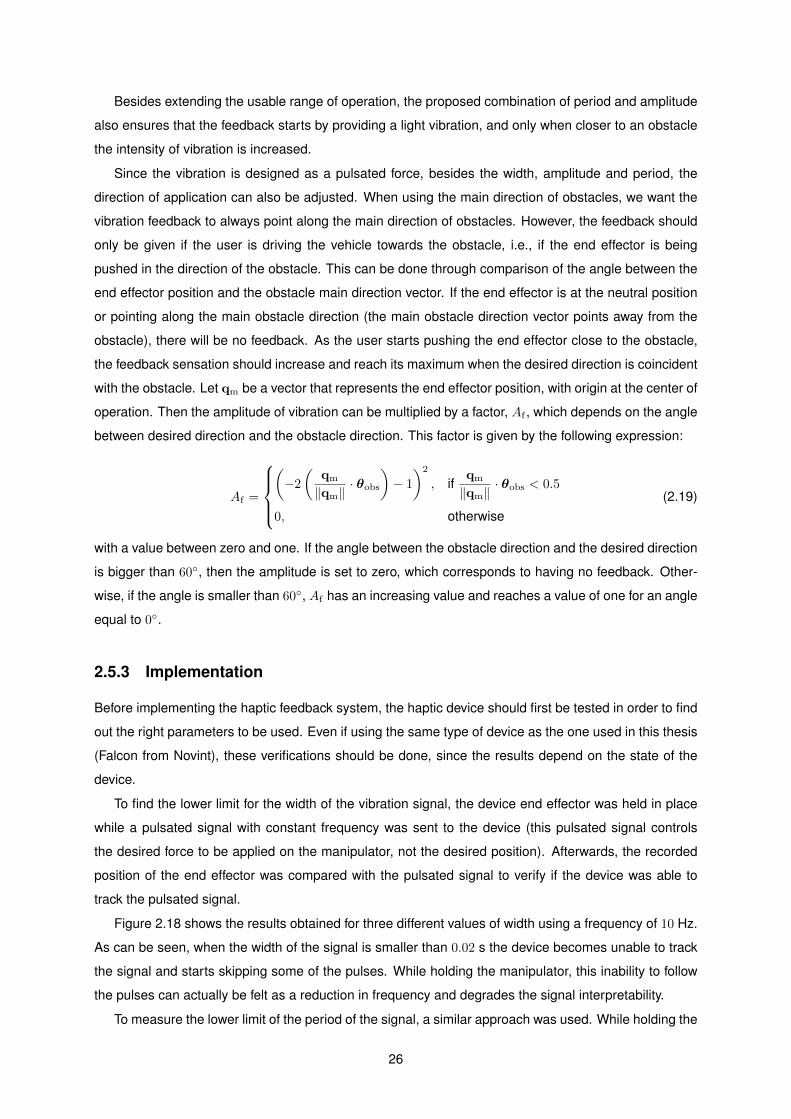
Besides extending the usable range of operation, the proposed combination of period and amplitude
also ensures that the feedback starts by providing a light vibration, and only when closer to an obstacle
the intensity of vibration is increased.
Since the vibration is designed as a pulsated force, besides the width, amplitude and period, the
direction of application can also be adjusted. When using the main direction of obstacles, we want the
vibration feedback to always point along the main direction of obstacles. However, the feedback should
only be given if the user is driving the vehicle towards the obstacle, i.e., if the end effector is being
pushed in the direction of the obstacle. This can be done through comparison of the angle between the
end effector position and the obstacle main direction vector. If the end effector is at the neutral position
or pointing along the main obstacle direction (the main obstacle direction vector points away from the
obstacle), there will be no feedback. As the user starts pushing the end effector close to the obstacle,
the feedback sensation should increase and reach its maximum when the desired direction is coincident
with the obstacle. Let qm be a vector that represents the end effector position, with origin at the center of
operation. Then the amplitude of vibration can be multiplied by a factor, Af , which depends on the angle
between desired direction and the obstacle direction. This factor is given by the following expression:
Af =
(−2(
qm
‖qm‖· θobs
)− 1
)2
, ifqm
‖qm‖· θobs < 0.5
0, otherwise(2.19)
with a value between zero and one. If the angle between the obstacle direction and the desired direction
is bigger than 60◦, then the amplitude is set to zero, which corresponds to having no feedback. Other-
wise, if the angle is smaller than 60◦, Af has an increasing value and reaches a value of one for an angle
equal to 0◦.
2.5.3 Implementation
Before implementing the haptic feedback system, the haptic device should first be tested in order to find
out the right parameters to be used. Even if using the same type of device as the one used in this thesis
(Falcon from Novint), these verifications should be done, since the results depend on the state of the
device.
To find the lower limit for the width of the vibration signal, the device end effector was held in place
while a pulsated signal with constant frequency was sent to the device (this pulsated signal controls
the desired force to be applied on the manipulator, not the desired position). Afterwards, the recorded
position of the end effector was compared with the pulsated signal to verify if the device was able to
track the pulsated signal.
Figure 2.18 shows the results obtained for three different values of width using a frequency of 10 Hz.
As can be seen, when the width of the signal is smaller than 0.02 s the device becomes unable to track
the signal and starts skipping some of the pulses. While holding the manipulator, this inability to follow
the pulses can actually be felt as a reduction in frequency and degrades the signal interpretability.
To measure the lower limit of the period of the signal, a similar approach was used. While holding the
26

(a)
positionpulse(b)
time [s]0 0.5 1 1.5 2
(c)
Figure 2.18: Master device response to pulsated signal with different width values and constant fre-quency equal to 10 Hz. (a) width = 0.02 s. (b) width = 0.015 s. (c) width = 0.010 s.
end effector, a pulsated signal was sent to the master controller with constant width and which frequency
was changed between tests. Afterwards, the recorded position of the end effector was compared with
the desired signal. The results obtained for different values of period are presented in Fig. 2.19. As can
be observed, the device started to fail tracking the signal for periods with value smaller than 0.04 s which
corresponds to a frequency of 25 Hz. Once again, the lower limit of the period corresponds to the lowest
value of period where the device is still capable of tracking the desired pulsated signal.
(a)
positionpulse(b)
time [s]0 0.2 0.4 0.6 0.8 1
(c)
Figure 2.19: Master device response to pulsated signal with different period values and constant widthequal to 0.02 s. (a) period = 0.04 s. (b) period = 0.035 s. (c) period = 0.030 s.
The previous results indicate that, using the Novint Falcon, the smallest values that can be used for
width and period for the vibration feedback are 0.02 s and 0.04 s respectively. Since the obtained values
are above the optimal sensitive bandwidth, 150 and 300 Hz, they can be used for implementation. The
pulse width of the vibration signal was set as constant and equal to 0.02 s. The value of 0.04 s was
used as the lower boundary of the signal period. For the upper boundary of the signal period, a value
of 0.1 s was used. The value 0.1 corresponds to the highest value for which the signal was still easily
27

and quickly perceived as a warning signal. The resulting feedback has a frequency that varies from 10
to 25 Hz, which is outside and below the optimal bandwidth.
2.5.4 Methods Comparison Results
With the objective of comparing the effectiveness of the developed vibration haptic feedback with feed-
backs normally used in teleoperation, an experiment was conducted. In this experiment, subjects had
to identify the direction of a virtual obstacle through a haptic feedback transmitted by the master device.
Setup
Three haptic feedbacks were tested during this experimentation: force feedback, stiffness feedback and
vibration feedback. Remembering, the force feedback acts as constant force that points away from the
obstacle and which intensity increases with proximity to the obstacle; the stiffness feedback increases
the stiffness of the master device when the end effector is moved towards the obstacle, stiffness increase
is proportional to the proximity to obstacle; finally, the vibration feedback causes the end effector to
vibrate when moved towards an obstacle, vibration frequency increases with proximity to obstacle.
During this experiment, each subject had to complete eighteen trials, six trials for each type of feed-
back. In each trial, a virtual obstacle would appear in one of eight possible directions in the horizontal
plane. As time passes during a round, the distance to the obstacle reduces at a steady rate, increasing
the force feedback intensity, and consequently, making the identification of the obstacle easier. At the
beginning of each trial, the distance to the obstacle is equal to the warning radius, corresponding to
minimum feedback activity. After twenty seconds it reaches maximum feedback activity. A round ends
when the user makes a guess, independently of being right or wrong. To find the obstacle direction,
subjects had to move the master end effector and try to feel the haptic feedback. Figure 2.20 presents
the visual interface of this experiment. After identifying the location of the obstacle, subjects could move
the haptic device to directly point a direction and select it by pressing a button on the device. The order
of the eighteen rounds and the direction of obstacles was randomly generated for each subject.
Figure 2.20: Visual interface, one button for each direction.
28

Twenty eight subjects with little to no experience using haptic devices participated in this experiment.
The subjects were informed of the objectives of the task and about the presence of different haptic
feedbacks. However, the subjects were not aware of how many different feedbacks were used, or how
they worked. The master device used was the 3 DOF fully-actuated haptic joystick Novint Falcon. The
performance evaluation of each haptic feedback was based on the number of correct guesses and on
the time taken to make a decision.
Results and discussion
The main results of the haptic experiment are shown in Fig. 2.21. A full-factorial ANOVA [53] test was
applied. In average, subjects correctly answered 67.2 % of the times using vibration feedback, against
37.5 % and 45.8 % for force and stiffness feedbacks respectively - see Fig. 2.21(a). The respective
average response times for vibration, force and stiffness feedbacks are 13.48 s, 16.98 s and 18.33 s -
Fig. 2.21(b).
force sti, vib
corr
ect
answ
ers
[%]
0
20
40
60
80
100
(a) Percentage of correct answers for each hapticfeedback. ANOVA test (p<0.001).
force sti, vib
tim
e[s]
0
10
20
30
40
(b) Average responde time for each haptic feed-back. ANOVA test (p<0.01).
Figure 2.21: Main results of haptic experiment for each type of feedback: force, stiffness and vibrationfeedback. Central mark = median; Box = 25th and 75th percentiles; whiskers = min and max values.
The obtained results show that the vibration feedback outperformed the two other feedbacks in both
response time and perception transmission efficiency. As expected, even with low intensity, vibration
allows the user to quickly gain awareness of an obstacle presence. By moving close to an obstacle,
stiffness and vibration feedback intensity would increase making it easier to select a direction. On the
other side, subjects had more difficulty choosing between adjacent directions when using the force
feedback.
29

30

Chapter 3
2D Experiment
With the purpose of comparing different haptic feedbacks and two collision avoidance systems in a
real case scenario, we conducted an experiment which consists of solving an unseen maze. During
this experiment, subjects had to teleoperate a custom made omnidirectional ground vehicle through an
unseen and unknown obstacle-laden course.
3.1 Platform OMNI-ANT
The vehicle being teleoperated during this experiment is the OMNI-ANT shown in figure 3.1. This vehicle
was designed as an omnidirectional vehicle to obtain a movement similar to the 2D motion of a typical
multirotor with altitude regulation. The holonomic movement is achieved with three omni wheels present
in the vehicle that allow the vehicle to move and rotate in any desired direction in the plane.
Figure 3.1: Slave vehicle, OMNI-ANT.
The central processing unit of the vehicle is an Arduino Mega ADK and the motors are controlled via
a MD25 motor controller board. The communication with the master is done wirelessly through an XBee
31

radio module. To perceive its surroundings, the vehicle is equipped with a Hokuyo URG-04LX-UG01, a
planar LIDAR scanner. The sensor main characteristics are presented in table 3.1.
Table 3.1: LIDAR scanner main characteristics.
Model URG-04LX-UG01
Output digitalCommunication USBRange 4 mAccuracy ± 3 % of measurementSample rate 10 HzScan angle 240◦
Angular resolution 0.36◦
3.2 Goals and Objectives
In this experiment, the three haptic feedbacks were implemented and compared: force feedback, stiff-
ness feedback and vibration feedback. An extra case was implemented where no haptic feedback was
used. This case should allow a better evaluation of the haptic feedbacks effectiveness. Furthermore,
the two different anti-collision methods (avoidance and deconfliction) were tested, both using the allowed
velocity space system.
The evaluation of each method was based on the following variables: task completion time, NASA
TLX workload index [54] and the results of questionnaires made to the user after each task. The task
completion time is the total time required to complete the maze. After each run, subjects were asked to
rate their workload using the NASA TLX rating scale, which assumes that the user workload is composed
of six sources: mental demand, physical demand, temporal demand, performance, effort and frustration
level. For each source, subjects use a scale to provide a classification from low to high. Besides
completing the NASA TLX, subjects also answered the following questionnaire:
• Was it easy to be aware of obstacles?
• Was it confortable to operate the vehicle?
• Was it easy to execute the task?
• Was the force felt on the manipulator helpful?
For each question, subjects selected a value from one to five, where one corresponds to ‘No’ and five to
‘Yes’.
3.3 Procedure
During this experiment, each subject had to complete a task that consists of teleoperating the slave
vehicle, OMNI-ANT, through an unseen maze. This task was to be completed eight times by each
32

subject, four times using the avoidance anti-collision method and four times using the deconfliction anti-
collision method. For each anti-collision method, four different haptic feedbacks were used (one haptic
feedback for each trial): force feedback, stiffness feedback, vibration feedback and no feedback. In an
attempt to reduce the learning curve effect and to obtain unbiased results, the order of the eight trials
was randomly generated for each subject.
3.4 User Interface
The user interface was composed of a screen, a haptic device and a keyboard and mouse used to
answer the questionnaires. As can be seen in Fig. 3.2(a), the view of the user was blocked, making it
impossible to see the vehicle and the maze.
The haptic device used during this experiment is the Falcon from Novint (Fig. 3.2(b)). This device is
connected to a desktop computer running Matlab, which controls the master device and connects with
the slave wirelessly though a XBee. The linear velocity of the vehicle is controlled through translation of
the master device end effector in a horizontal plane (vertical movement is not used in this experiment).
The rotation of the vehicle is obtained by pressing one of two buttons present in the grip (one button
for clockwise rotation and other for anti-clockwise rotation). If released, a spring and damper system
pushes the end effector to the center of operation causing the vehicle to stop.
(a) User interface. (b) Novint Falcon.
Figure 3.2: Master system.
During operation, a top view of the slave surroundings was displayed on the screen (Fig. 3.3). This
image is created using the distance values obtained by the LIDAR scanner. The vehicle is drawn in the
middle of the display and the detected obstacles appear around it, resulting in a view similar to a radar
image. After each trial, a questionnaire would appear on the screen so subjects could promptly fill them
online. Furthermore, this allowed to immediately save all results in a format suitable for post analysis.
33

Figure 3.3: visual interface. LIDAR scanner top view.
3.5 Subjects and Instructions
Altogether, twenty eight subjects between ages 20 and 49 years of age with little to no experience using
haptic devices participated in this experiment. Before beginning the experiment, subjects were told
about the presence of different types of haptic feedbacks and to be aware of them. However, they were
not told how many different feedbacks existed, neither the dissimilarities between them. Furthermore,
subjects did not know which feedback was being used at which round or the existence of a round without
feedback. As a main goal, subjects were challenged to find the exit of the maze as fast as possible, while
maintaining a special attention to the haptic feedbacks.
With the purpose of obtaining some insight of how the vehicle moves and to gain some sensibility
with the haptic device, before starting the tests, subjects were allowed to pilot the vehicle while seeing it.
Afterwards, the vehicle was placed inside the unseen and unknown maze and subjects were required to
teleoperate the vehicle towards the exit of the maze. The trial ended when the vehicle exited the maze.
During tests the protocol was not to give any instructions regarding the maze or the vehicle control. After
completing each trial, subjects had to fill the NASA TLX rating sheet, which promptly appeared on the
screen. Upon completion of the first questionnaire, the second questionnaire (previously mentioned)
appeared. At the end of the experiment, subjects were asked to talk about how they felt during this
experience, what they liked the most and what they did not like. This allowed to obtain, in a more
informal way, information that could not be obtained through specific questionnaires.
3.6 Maze
The maze used during this experiment is shown in figure 3.4. The maze is shaped like a ‘U’ with some
characteristics intended to decrease proximity to obstacles and consequently increase haptic feedback
activity. Halfway, an obstacle placed in the center of the 180 deg turn creates two possible paths. While
34

the exterior path is quite wide, allowing an easy passage, the inner path width is just slightly wider than
twice the danger radius. As a result, the user has to be a little insistent to pass through this choke point.
If this path was even tighter, the obstacle avoidance system would not allow the vehicle to go through.
At the end of the maze, an obstacle forces the user to move slightly to the right, once again to increase
haptic feedback activity.
The obstacle avoidance parameters used during this experiment were: 0.5 m, 0.25 m and 0.2 m,
respectively for the warning radius, danger radius and critical radius.
Figure 3.4: Top view of the maze used for experiments.
3.7 Results
This section presents the main results of this 2D experiment. Before examining the results, it was verified
that the first trial done by each subject was affected mostly by the subjects capacities, rather than the
influence of the methods used. Consequently, the first trial, and for a few cases the second trial, of each
subject, were not included in the results analysis.
A first analysis compares the overall results using the avoidance system and the deconfliction system.
A significant decrease in the duration of the task when the deconfliction system is used is confirmed
in the results of Fig. 3.5(a), with a reduction in the average completion time from 46.94 s to 34.30 s.
The NASA TLX scores (Fig 3.5(b)) indicate that the deconfliction system resulted in less workload, as
expected.
The mean and standard deviation of the questionnaires results between avoidance and deconfliction
systems can be observed in table 3.2. Results indicate that subjects considered that the deconfliction
system provides a more comfortable teleoperation and made the task easier, one way ANOVA results
confirm this difference (p<0.001). On the other hand, the influence of the anti-collision system in obsta-
cle awareness was statistically insignificant. The effect of the haptic feedback was also unaffected by
the anti-collision system used.
Regarding the different haptic feedbacks used, figure 3.6(b) shows a slight increase in workload for
35

AS DS
tim
e[s]
0
20
40
60
(a) Task completion time. ANOVA test (p<0.0001).
AS DS
work
load
0
20
40
60
(b) NASA-TLX scores. ANOVA test (p<0.001).
Figure 3.5: Comparison results between avoidance system (AS) and deconfliction system (DS). Centralmark = median; Box = 25th and 75th percentiles; whiskers = min and max values.
Table 3.2: Comparison of questionnaire results between anti-collisionsystems. Answers were scaled from one to five, being one ’No’ and five’Yes’.
Avoidance Deconfliction
meanstandarddeviation
meanstandarddeviation
Was it easy to beaware of obstacles?
4.54 0.68 4.74 0.60
Was it confortable tooperate the vehicle?
4.37 0.71 4.68 0.67
Was it easy toexecute the task?
4.39 0.63 4.68 0.60
Was the force felt onthe manipulator helpful?
3.78 1.20 3.69 1.49
the force feedback. However, the difference in workload between vibration feedback, stiffness feedback
and no feedback was statistically insignificant. Similarly, task completion time (see Fig. 3.6(a)), was not
affected by the type of feedback used, except for the force feedback in which an increase was noticed.
The increase in task completion time verified with force feedback may be due to the force feedback
ability to move the master device end effector to a non-neutral position, which may cause the vehicle to
do extra movements and consequently increase the time necessary to complete the task. Results also
show that subjects were slightly faster when using no haptic feedback. Since there were no collisions
or penalties for getting too close to obstacles, subjects could have a carefree operation. However, upon
receiving a feedback warning, subjects took more time to increase the distance to obstacle, resulting in
an increased operation safety at the cost of an increase in task completion time.
The mean and standard deviation of the values obtained from the questionnaires for each haptic
feedback is shown in table 3.3. Accordingly to the increase in workload when using the force feedback,
users also classified this feedback as the most uncomfortable. As expected, subjects considered the
case when no haptic feedback was used, to be the least helpful case. Nevertheless, using no haptic
36
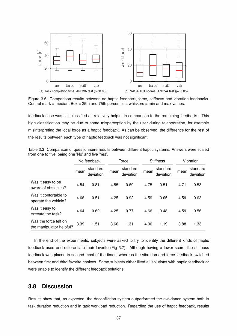
no force sti, vib
tim
e[s]
0
20
40
60
(a) Task completion time. ANOVA test (p<0.05).
no force sti, vib
work
load
0
20
40
60
(b) NASA-TLX scores. ANOVA test (p<0.05).
Figure 3.6: Comparison results between no haptic feedback, force, stiffness and vibration feedbacks.Central mark = median; Box = 25th and 75th percentiles; whiskers = min and max values.
feedback case was still classified as relatively helpful in comparison to the remaining feedbacks. This
high classification may be due to some misperception by the user during teleoperation, for example
misinterpreting the local force as a haptic feedback. As can be observed, the difference for the rest of
the results between each type of haptic feedback was not significant.
Table 3.3: Comparison of questionnaire results between different haptic systems. Answers were scaledfrom one to five, being one ’No’ and five ’Yes’.
No feedback Force Stiffness Vibration
meanstandarddeviation
meanstandarddeviation
meanstandarddeviation
meanstandarddeviation
Was it easy to beaware of obstacles?
4.54 0.81 4.55 0.69 4.75 0.51 4.71 0.53
Was it confortable tooperate the vehicle?
4.68 0.51 4.25 0.92 4.59 0.65 4.59 0.63
Was it easy toexecute the task?
4.64 0.62 4.25 0.77 4.66 0.48 4.59 0.56
Was the force felt onthe manipulator helpful?
3.39 1.51 3.66 1.31 4.00 1.19 3.88 1.33
In the end of the experiments, subjects were asked to try to identify the different kinds of haptic
feedback used and differentiate their favorite (Fig 3.7). Although having a lower score, the stiffness
feedback was placed in second most of the times, whereas the vibration and force feedback switched
between first and third favorite choices. Some subjects either liked all solutions with haptic feedback or
were unable to identify the different feedback solutions.
3.8 Discussion
Results show that, as expected, the deconfliction system outperformed the avoidance system both in
task duration reduction and in task workload reduction. Regarding the use of haptic feedback, results
37
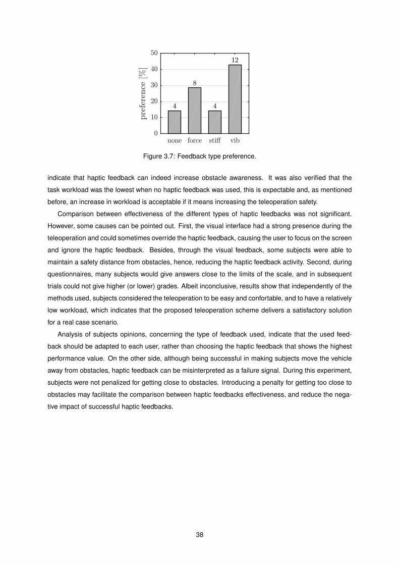
none force sti, vibpre
fere
nce
[%]
0
10
20
30
40
50
4
8
4
12
Figure 3.7: Feedback type preference.
indicate that haptic feedback can indeed increase obstacle awareness. It was also verified that the
task workload was the lowest when no haptic feedback was used, this is expectable and, as mentioned
before, an increase in workload is acceptable if it means increasing the teleoperation safety.
Comparison between effectiveness of the different types of haptic feedbacks was not significant.
However, some causes can be pointed out. First, the visual interface had a strong presence during the
teleoperation and could sometimes override the haptic feedback, causing the user to focus on the screen
and ignore the haptic feedback. Besides, through the visual feedback, some subjects were able to
maintain a safety distance from obstacles, hence, reducing the haptic feedback activity. Second, during
questionnaires, many subjects would give answers close to the limits of the scale, and in subsequent
trials could not give higher (or lower) grades. Albeit inconclusive, results show that independently of the
methods used, subjects considered the teleoperation to be easy and confortable, and to have a relatively
low workload, which indicates that the proposed teleoperation scheme delivers a satisfactory solution
for a real case scenario.
Analysis of subjects opinions, concerning the type of feedback used, indicate that the used feed-
back should be adapted to each user, rather than choosing the haptic feedback that shows the highest
performance value. On the other side, although being successful in making subjects move the vehicle
away from obstacles, haptic feedback can be misinterpreted as a failure signal. During this experiment,
subjects were not penalized for getting close to obstacles. Introducing a penalty for getting too close to
obstacles may facilitate the comparison between haptic feedbacks effectiveness, and reduce the nega-
tive impact of successful haptic feedbacks.
38

Chapter 4
3D Experiment
In the previous experiment, subjects compared different haptic feedbacks through the teleoperation of an
unmanned ground vehicle. Even though results were satisfactory, the UGV represents a 2D scenario and
does not allow to classify the efficiency of haptic feedbacks in 3D scenarios, e.g., during teleoperation
of a quadcopter. In order to evaluate the proposed teleoperation scheme and the efficiency of the haptic
feedback in a 3D scenario, a second experiment was conducted. In this second experiment, subjects
had to control a simulated quadcopter through three unknown virtual mazes.
4.1 Quadcopter Model
This section presents the model and the control system of the virtual quadcopter used in this experiment.
The model of the vehicle and respective dynamics controller were provided by Ruivo [55], therefore only
a brief description is presented.
The stabilized attitude dynamics of the vehicle was designed as second order decoupled systems for
roll and pitch angles, and as a first order system for yaw angular velocity, as described in the following
equation:
φ
φ
θ
θ
ψ
ψ
=
0 1 0 0 0 0
−ωφn2
2ζφωφn 0 0 0 0
0 0 0 1 0 0
0 0 −ωθn2
2ζθωθn 0 0
0 0 0 0 0 1
0 0 0 0 0 − 4
Tψs
φ
φ
θ
θ
ψ
ψ
+
0 0 0
−ωφn2
0 0
0 0 0
0 −ωθn2
0
0 0 0
0 0 4
Tψs
φr
θr
ψr
(4.1)
where the quadcopter attitude is defined by the three Euler angles φ, θ and ψ, respectively, roll, pitch
and yaw, defined in the body fixed frame of reference, ωn is the natural frequency, ζ is the damping
coefficient and Ts is the settling time of the respective angle.
Afterwards, the position dynamics of the vehicle, as seen from the global frame of reference, is
39
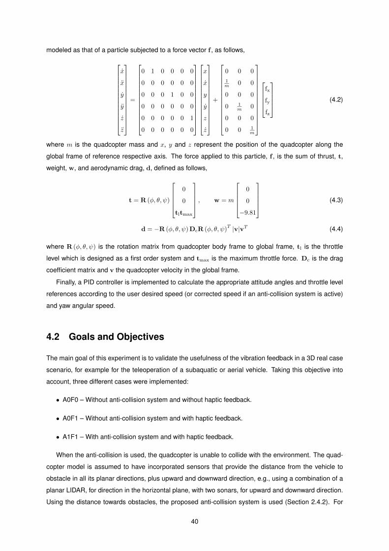
modeled as that of a particle subjected to a force vector f , as follows,
x
x
y
y
z
z
=
0 1 0 0 0 0
0 0 0 0 0 0
0 0 0 1 0 0
0 0 0 0 0 0
0 0 0 0 0 1
0 0 0 0 0 0
x
x
y
y
z
z
+
0 0 0
1m 0 0
0 0 0
0 1m 0
0 0 0
0 0 1m
fx
fy
fz
(4.2)
where m is the quadcopter mass and x, y and z represent the position of the quadcopter along the
global frame of reference respective axis. The force applied to this particle, f , is the sum of thrust, t,
weight, w, and aerodynamic drag, d, defined as follows,
t = R (φ, θ, ψ)
0
0
tltmax
, w = m
0
0
−9.81
(4.3)
d = −R (φ, θ, ψ)DcR (φ, θ, ψ)T |v|vT (4.4)
where R (φ, θ, ψ) is the rotation matrix from quadcopter body frame to global frame, tl is the throttle
level which is designed as a first order system and tmax is the maximum throttle force. Dc is the drag
coefficient matrix and v the quadcopter velocity in the global frame.
Finally, a PID controller is implemented to calculate the appropriate attitude angles and throttle level
references according to the user desired speed (or corrected speed if an anti-collision system is active)
and yaw angular speed.
4.2 Goals and Objectives
The main goal of this experiment is to validate the usefulness of the vibration feedback in a 3D real case
scenario, for example for the teleoperation of a subaquatic or aerial vehicle. Taking this objective into
account, three different cases were implemented:
• A0F0 – Without anti-collision system and without haptic feedback.
• A0F1 – Without anti-collision system and with haptic feedback.
• A1F1 – With anti-collision system and with haptic feedback.
When the anti-collision is used, the quadcopter is unable to collide with the environment. The quad-
copter model is assumed to have incorporated sensors that provide the distance from the vehicle to
obstacle in all its planar directions, plus upward and downward direction, e.g., using a combination of a
planar LIDAR, for direction in the horizontal plane, with two sonars, for upward and downward direction.
Using the distance towards obstacles, the proposed anti-collision system is used (Section 2.4.2). For
40

the cases without collision avoidance system, it is possible to collide. In case of collision, a red light
flashes on the screen and the user is unable to move the vehicle for three seconds.
In this experiment only the vibration feedback is implemented. If the haptic feedback is activated,
subjects should feel a vibration on the manipulator when close to obstacles. Otherwise, if the haptic
feedback is not activated, subjects will not receive any type of feedback.
The evaluation of each case was based on the following variables: task completion time, number of
collisions and the results of questionnaires made to the user after each task. The task completion time
is the total time required to complete the maze. The number of collisions is the total number of collisions
during that trial. The questionnaire is composed of the following questions:
• Was it easy to be aware of obstacles?
• Was it confortable to operate the vehicle?
• Was it easy to execute the task?
• How strong was the force felt on the manipulator?
• Was the force felt on the manipulator helpful?
For each question, subjects selected a value from one to ten, where one corresponds to ‘No’ and
ten to ‘Yes’, except for the fourth question where one corresponds to ‘Did not felt it’ and ten to ‘Very
strong’. In the first experiment (Chapter 3) some subjects gave a response close to the maximum on
their first trial. Consequently, in subsequent trials, these subjects could not respond with a higher value.
By increasing the response range to ten, instead of the previously used value of five, users tendency to
choose responses close to the extremes is reduced. Furthermore, using a range between one and ten
allows a better differentiation of responses. Adding to this, since there is an even number of responses,
subjects are compelled to choose a negative or positive response.
4.3 Procedure
During this experiment, each subject had to complete a task that consists of teleoperating a virtual
quadcopter through one of three different 3D mazes. Each subject repeated this task nine times, three
times for each maze. For each maze the three different cases were used: A0F0, A0F1 and A1F1, one
for each trial. In an attempt to reduce the learning curve effect and to obtain unbiased results, the order
of the nine trials was randomly generated for each subject.
At the end of the experiment, subjects were asked if they wanted to repeat the experiment. If they
answered yes, then they would be able to repeat the nine trials (with a new order), resulting in extra
results. A post analysis with these extra results was done taking into account users added experience.
41

4.4 User Interface
As in the first experiment, the user interface was composed of a screen, a haptic device and a keyboard
and mouse used to answer the questionnaires, Fig. 3.2(a).
As before, the haptic device used during this experiment is the Falcon from Novint (Fig. 3.2(b)). This
device is connected to a desktop computer running Matlab, where a second Matlab instance runs the
simulator. The linear velocity of the vehicle is controlled through translation of the master device end
effector, including upward and downward directions. Rotation of the vehicle is obtained by pressing one
of two buttons present on the grip (one button for clockwise rotation and other for anti-clockwise rotation).
If released, a spring and damper system pushes the end effector to the center of operation causing the
vehicle to hover.
During operation, subjects had a first person view of the vehicle on the screen (Fig. 4.1). This view
is similar to when a camera is mounted on the vehicle, facing forward. To achieve this perspective, the
point of view is attached to the vehicle body fixed frame of reference and moves with the same attitude
of the vehicle - see Fig. 4.1(c) where the quadcopter is in a rolled position.
(a) (b) (c)
Figure 4.1: Examples of user visual interface.
4.5 Subjects and Instructions
Altogether, forty six subjects between 20 and 57 years of age with little to no experience using haptic
devices participated in this experiment. Contrary to what was done in the first experiment, before be-
ginning the experiment, subjects were told about the three possible cases, how they work and also how
the vibration feedback functions. They were told about the existence of different mazes, but were not
told how many different mazes they had to complete. Furthermore, subjects did not know which case
or maze was being used at each trial. As a main goal, subjects were challenged to find the exit of the
maze as fast as possible, while maintaining a special attention to the haptic feedbacks.
With the purpose of obtaining some insight on how the vehicle moves and to gain some sensibility
with the haptic device, before starting the tests, subjects were allowed to pilot the vehicle inside a small
square room without anti-collision system and without haptic feedback. Afterwards, subjects had to
complete one of three different mazes. The trial ended when the quacopter exited the maze. After com-
pleting each trial, subjects had to fill the previously mentioned questionnaire, which promptly appeared
42

on the screen, which also allowed to immediately save all results in a format suitable for post analysis.
During tests the protocol was not to give any instructions regarding the maze or the vehicle control. At
the end of the experiment subjects gave small comments regarding the experience.
4.6 Maze
The mazes used during this experiment are shown in figures 4.2, 4.3 and 4.4. These mazes have one
characteristic in common, they were designed with the intent of decreasing proximity to obstacles and
consequently increase haptic feedback activity. Through a combination of different rooms, corridors
and sideways, upward and downward curves, subjects are required to move the haptic manipulator in
all directions in order to complete each maze. The dark area in the first and second mazes (Figs. 4.2
and 4.3) represent a “no light” zone. Upon entering this zone, lights are turned off, causing a significant
decrease in visual perception. After exiting the “no light” zone, light returns to the normal state. The red
area in mazes one and three represents a usual obstacle which subjects had to pass below.
Theses mazes are built using the Matlab patch function. Afterwards, during operation, only the point
of view is modified guaranteeing the necessary speed to run the simulation in real time. The designed
simulator can easily be adapted for new experiments with different mazes and also for experiments of
different nature, for example, for biological learning where one might be interest in understanding how
users behave when confronted with certain obstacles.
The obstacle avoidance parameters used during this experiment were: 1.0 m, 0.3 m and 0.2 m,
respectively for the warning radius, danger radius and critical radius. A collision would occur at a distance
of 0.1 m.
50
40
x [m]
30
20
10
00 5
1015
y [m]
20
5
0
-5
z[m
]
(a) Isometric view.
x[m
]
0
5
10
15
20
25
30
35
40
45
50
y [m]0 5 101520
z [m]-505
(b) Top and side view.
Figure 4.2: Simulation maze 1. Blue dot represents initial position. Black area: “no light” zone. Redarrow: maze exit.
43

35
30
25
x [m]
20
15
10
5
00
5
10
y [m]
0
5
-5
z[m
]
(a) Isometric view.x
[m]
0
5
10
15
20
25
30
35
40
45
50
y [m]0 5 101520
z [m]0510
(b) Top and side view.
Figure 4.3: Simulation maze 2. Blue dot represents initial position. Black area: “no light” zone. Redarrow: maze exit.
4035
30
x [m]
2520
1510
500
510
15
y [m]
2025
-5
0
5
z[m
]
(a) Isometric view.
x[m
]
0
5
10
15
20
25
30
35
40
45
50
y [m]0 5 101520
z [m]0510
(b) Top and side view.
Figure 4.4: Simulation maze 3. Blue dot represents initial position. Red arrow: maze exit.
44

4.7 Results
This section presents the main results obtained. A first analysis compares the task completion time and
number of collisions between the three use cases. Figure 4.5(a) shows a reduction in task completion
time when the haptic feedback is used, with a reduction in the average completion time from 62.8 s
to 58.7 s and a further reduction to 57.7 s if the anti-collision system is used. Using the A1F1 case,
subjects were able to complete the maze almost 10 % faster in comparison with the A0F0 case. Results
present in Fig. 4.5(b) show that the use of haptic feedback had a major impact in reducing the number
of collisions, achieving a mean reduction of almost 50 % from 2.16 to 1.23 collisions for each trial. When
the anti-collision system was used, there were no collisions, so this case is not graphically represented.
A0F0 A0F1 A1F1
tim
e[s]
0
20
40
60
80
100
120
(a) Task completion time. ANOVA test (p<0.05).
A0F0 A0F1
Collisio
ns
0
2
4
6
(b) Number of collisions. ANOVA test (p<0.001).
Figure 4.5: Results comparison between different cases. Central mark = median; Box = 25th and 75thpercentiles; whiskers = min and max values.
The results of the questionnaire are presented in Fig. 4.6 according to the use case. Figure 4.6(a)
shows that, as expected, when using a haptic feedback, subject’s obstacle awareness increased signif-
icantly, with mean response values increasing from 7.70 to 8.56 and 8.67, respectively for the A0F1 and
A1F1 cases. Regarding the operation comfort, Fig. 4.6(b) shows similar results, with mean response
values increasing from 8.13 to 8.75 and 8.83, respectively for the A0F0, A0F1 and A1F1 cases.
Figure 4.6(c) shows an almost linear increase in task easiness for the three cases, with mean re-
sponse values varying between 7.42, 8.25 and 8.58, respectively for the A0F0, A0F1 and A1F1 cases.
Finally, figures 4.6(d) and 4.6(e) show the results of the questions concerning the haptic feedback.
For the A0F0 case, there was no haptic feedback applied, consequently subjects did not feel it and
therefore this case is not represented. Regarding the intensity of the haptic feedback, results indicate
that subjects felt the haptic feedback with slightly more intensity when the anti-collision system was
used. This increase in intensity is justified, since without colliding, subjects could stay more time close
to obstacles, therefore increasing the haptic feedback activity. In some cases, around 8 % of the trials,
users were able to maintain a safe operation without getting close to obstacles. Consequently, although
the haptic feedback was active, subjects did not feel the haptic feedback. For these cases, the response
to the last question loses meaning and therefore was not included in results analyses. Responses
regarding the helpfulness of haptic feedback indicate that the haptic feedback was considered helpful
45

independently of using an anti-collision system or not, with a mean response value of 8.41 and 8.40,
respectively for the A0F1 and A1F1 cases. In overall, the effectiveness of the haptic feedback was not
statistically affected by the use of an anti-collision system.
A0F0 A0F1 A1F1
Answ
er
2
4
6
8
10
(a) Was it easy to be aware of obstacles?ANOVA test (p<0.0001).
A0F0 A0F1 A1F1
Answ
er2
4
6
8
10
(b) Was it confortable to operate the ve-hicle? ANOVA test (p<0.001).
A0F0 A0F1 A1F1
Answ
er
2
4
6
8
10
(c) Was it easy to execute the task?ANOVA test (p<0.0001).
A0F1 A1F1
Answ
er
2
4
6
8
10
(d) How strong was the force felt on themanipulator?
A0F1 A1F1
Answ
er
2
4
6
8
10
(e) Was the force felt on the manipulatorhelpful?
Figure 4.6: Questionnaire results comparison for different cases. Central mark = median; Box = 25thand 75th percentiles; whiskers = min and max values.
4.8 Discussion
Analysis of this experiment results shows that, as expected, the use of haptic feedback not only in-
creases users obstacle perception, as it also significantly reduces task completion time and improves
operation safety through reduction of collisions. The introduction of an anti-collision system provided
a further improve in task completion time and safety. Although the reduction in task completion time
was not as significant as expected when using an anti-collision system, it is important to notice that the
collision penalty used (unable to move for three seconds) was very indulgent in comparison with a real
case scenario.
One possible problem that can be pointed out during haptic teleoperation, is that the haptic feedback
may be considered a source of distraction and, consequently, may difficult users operation and increase
the task workload. Results, however, indicate that the haptic feedback not only improved users perfor-
mance, as it also improved comfort and easiness during operation. Subjects also considered that the
level of intensity of the haptic feedback was adequate. Most subjects considered the haptic feedback to
be strong enough to be felt, but not too strong to cause discomfort.
A second objective of this experiment was to compare the effectiveness of the haptic feedback with
46

and without the use of an anti-collision system. On one side, with an anti-collision system, since there is
no risk of collision (in a real case this risk may still exist but is greatly reduced), users may consider that
the haptic feedback is forcing the user to do unnecessary movements. On the other side, with reduced
visibility of the vehicles surroundings, haptic feedback may help users understand if the desired path is
clear or not. Surprisingly, results show that the effectiveness of the haptic feedback was not affected
by the presence of an anti-collision system. Whether an anti-collision system is used or not, subjects
considered the haptic feedback to be equally helpful.
As a final remark, after concluding the experiment, subjects made a few comments and most of them
share the same conclusion: the haptic feedback was helpful in perceiving the vehicle surroundings and
during the cases where it was not active, subjects wanted it to be activated.
47

48

Chapter 5
Conclusions
The use of unmanned vehicles in operations that require human intervention is gaining relevance. How-
ever, typically, users have a reduced awareness of the vehicle surroundings and are not provided with
the level of abstraction required for these complex tasks.
Through implementation of the proposed haptic teleoperation scheme, the control of the vehicle
becomes more intuitive, increasing user comfort and decreasing task workload. Furthermore, the use of
a haptic feedback allowed to greatly improve user obstacle awareness, increasing teleoperation safety
and efficiency.
When compared with other methods present in the literature, the proposed obstacle perception
method presents a much simpler solution, requiring less computational time. Furthermore, resulting
in a single vector containing the obstacles main direction, the proposed solution can simultaneously be
used as a reference for both the anti-collision system and the haptic feedback. Since the obstacle per-
ception method is based only on distance to obstacle, the transparency of the teloperation increases in
comparison with other methods based on time to impact.
An anti-collision system that uses the obstacle main distance was also designed. As the obstacle
perception method, this anti-collision system requires a reduced processing time in comparison with
other methods. For the anti-collision method, two sub-modes were implemented, avoidance and decon-
fliction. Comparison of these two sub-modes in an experiment where 28 users had to teleoperate an
UGV through an unseen maze, reveals that, as expected, the deconfliction sub-mode guarantees a sig-
nificant reduction in task completion time as well as in task workload. In opposition to typical solutions,
the anti-collision system was implemented directly in the vehicle, assuring that the vehicle will not collide
even if communication with the operator fails.
A novel haptic feedback based on vibration was introduced. This vibration feedback takes advantage
of the vibrotactile sensing to provide a better perception of the slave environment with reduced task
workload. An experiment where subjects had to point the direction of a single obstacle was conducted.
Results show that the vibration feedback outperformed other haptic feedbacks in both time required to
perceive the obstacle and direction precision. Nonetheless, results regarding the use of different haptic
feedbacks in a real scenario support that there is no optimal type of haptic feedback. Instead of finding a
49

unique type of haptic feedback, results indicate that the haptic feedback should be individually adapted
for each operator.
A simulator of a quadcopter was developed using appropriate dynamics. In this simulator, subjects
can see the front of the quadcopter as if a camera was attached to the vehicle. An experiment was
conducted where 46 subjects had to teleoperate the virtual quadcopter through three different mazes.
Results show that the use of a haptic feedback had a major impact in increasing obstacle awareness,
and also contributed to an increase in operation comfort and easiness. Furthermore, when using a
haptic feedback, the number of collisions reduced significantly, as well as the task completion time. The
impact of the haptic feedback helpfulness was even greater in these 3D scenarios than it was in the
previous 2D experiment. During this experiment, it was also verified that the helpfulness of the haptic
feedback is independent of whether an anti-collision system is used or not.
As final remark, it can be concluded that the proposed haptic teleoperation scheme provides an im-
proved solution for the teleoperation of unmanned vehicles with increased vehicle surroundings aware-
ness and reduction in task workload.
5.1 Future Work
In this thesis, the process of teleoperation was enriched with an anti-collision system and a vibration
haptic feedback. Results indicate that this methodology decreased the risk of the teleoperation and
increased the user awareness of the vehicle surroundings. Nevertheless, regarding the safety and
transparency in teleoperation, there is always room for improvement.
Taking into account this study results, the following recommendation and future investigation oppor-
tunities are given:
• Master device: Explore the use of other haptic manipulators to control the vehicle. The Falcon
worked well. However, this device presented some limitations in terms of force control. Other com-
mercial haptic devices could be used or alternatively a custom manipulator could be constructed.
• Admittance interface: Implementation of an admittance interface and comparison with the pro-
posed scheme. This solution would require a different master device since, as mentioned before,
the Falcon is not appropriate for admittance control.
• Vibration feedback: During implementation of the novel feedback, the vibration bandwidth was
limited by the master device characteristics. The performance of this scheme should improve if an
optimal bandwidth is used (150 to 300 Hz). Once again, a different master device could improve
the obtained results. Another solution is the use of custom made grip with actuators that could
vibrate in local points without using the movement of the end effector. Using this last solution
would allow to mix the vibration feedback (applied only on the grip vibrating components) with
other haptic feedback such as force or stiffness feedback.
• Obstacle perception: Experimentally compare the proposed obstacle perception methods with
50

other methods present in the bibliography that use a time to impact approach rather than a distance
to obstacle approach.
• Experiments: Conduct user studies using a physical UAV in an indoor scenario. The proposed tele-
operation scheme is ready to be implemented on a real UAV. However, an infrastructure equipped
with cameras and nets is necessary to supervise the experiment and guarantee users safety.
• Transparency: This thesis focus on haptic teleoperation. However, the improvement of a teleoper-
ation transparency is not restricted to haptic feedbacks. Some solutions may include other senses
such as vision and hearing. For example, visual cues such as a red light on screen, to warn the
user of close obstacles. Temperature could also be used to inform the user of the state of the
vehicle, e.g., the grip of the master device could become warmer when close to obstacles.
51

52

Bibliography
[1] T. B. Sheridan. Telerobotics. Automatica, 25(4):487–507, 1989.
[2] J. Marescaux, J. Leroy, F. Rubino, M. Smith, M. Vix, M. Simone, and D. Mutter. Transcontinental
robot-assisted remote telesurgery: feasibility and potential applications. Annals of surgery, 235(4):
487, 2002.
[3] D. W. Gage. Ugv history 101: A brief history of unmanned ground vehicle (ugv) development efforts.
Technical report, DTIC Document, 1995.
[4] T. Fong and C. Thorpe. Vehicle teleoperation interfaces. Autonomous robots, 11(1):9–18, 2001.
[5] B. Siciliano and O. Khatib. Springer handbook of robotics. Springer Science & Business Media,
2008.
[6] K. Dalamagkidis, K. P. Valavanis, and L. A. Piegl. On integrating unmanned aircraft systems into
the national airspace system: issues, challenges, operational restrictions, certification, and recom-
mendations, volume 54. Springer Science & Business Media, 2011.
[7] J. F. Keane and S. S. Carr. A brief history of early unmanned aircraft. Johns Hopkins APL Technical
Digest, 32(3):558–571, 2013.
[8] I. Sa and P. Corke. Close-quarters quadrotor flying for a pole inspection with position based vi-
sual servoing and high-speed vision. In Unmanned Aircraft Systems (ICUAS), 2014 International
Conference on, pages 623–631. IEEE, 2014.
[9] S. Emelianov, A. Bulgakow, and D. Sayfeddine. Aerial laser inspection of buildings facades using
quadrotor. Procedia Engineering, 85:140–146, 2014.
[10] L. F. Luque-Vega, B. Castillo-Toledo, A. Loukianov, and L. E. Gonzalez-Jimenez. Power line in-
spection via an unmanned aerial system based on the quadrotor helicopter. In Mediterranean
Electrotechnical Conference (MELECON), 2014 17th IEEE, pages 393–397. IEEE, 2014.
[11] S. Waharte and N. Trigoni. Supporting search and rescue operations with uavs. In Emerging
Security Technologies (EST), 2010 International Conference on, pages 142–147. IEEE, 2010.
[12] M. Waite. Journalism with flying robots. XRDS: Crossroads, The ACM Magazine for Students, 20
(3):28–31, 2014.
53

[13] S. C. Williams. Studying volcanic eruptions with aerial drones. Proceedings of the National
Academy of Sciences of the United States of America, 110(27):10881, 2013.
[14] W. Zang, J. Lin, Y. Wang, and H. Tao. Investigating small-scale water pollution with uav remote
sensing technology. In World Automation Congress (WAC), 2012, pages 1–4. IEEE, 2012.
[15] B. R. Husak. Quadrotor 3d intuitive flying. Bachelor’s thesis, Faculty of Mathematics and Physics
(MFF), Prague, June 2014. Id:134662.
[16] D. Lawrence et al. Stability and transparency in bilateral teleoperation. Robotics and Automation,
IEEE Transactions on, 9(5):624–637, 1993.
[17] P. F. Hokayem and M. W. Spong. Bilateral teleoperation: An historical survey. Automatica, 42(12):
2035–2057, 2006.
[18] E. Slawinski, V. Mut, P. Fiorini, L. R. Salinas, et al. Quantitative absolute transparency for bilateral
teleoperation of mobile robots. Systems, Man and Cybernetics, Part A: Systems and Humans,
IEEE Transactions on, 42(2):430–442, 2012.
[19] T. Lam, M. Mulder, and M. R. Van Paassen. Haptic feedback for uav tele-operation-force offset
and spring load modification. In Systems, Man and Cybernetics, 2006. SMC’06. IEEE International
Conference on, volume 2, pages 1618–1623. IEEE, 2006.
[20] T. M. Lam, M. Mulder, and M. M. van Paassen. Haptic interface in uav tele-operation using force-
stiffness feedback. In Systems, Man and Cybernetics, 2009. SMC 2009. IEEE International Con-
ference on, pages 835–840. IEEE, 2009.
[21] T. M. Lam, H. W. Boschloo, M. Mulder, and M. M. Van Paassen. Artificial force field for haptic
feedback in uav teleoperation. Systems, Man and Cybernetics, Part A: Systems and Humans,
IEEE Transactions on, 39(6):1316–1330, 2009.
[22] A. M. Brandt and M. B. Colton. Haptic collision avoidance for a remotely operated quadrotor uav in
indoor environments. In Systems Man and Cybernetics (SMC), 2010 IEEE International Conference
on, pages 2724–2731. IEEE, 2010.
[23] T. Lam, M. Mulder, and M. Van Paassen. Haptic feedback in uninhabited aerial vehicle teleoperation
with time delay. Journal of guidance, control, and dynamics, 31(6):1728–1739, 2008.
[24] R. Mahony, F. Schill, P. Corke, and Y. S. Oh. A new framework for force feedback teleoperation of
robotic vehicles based on optical flow. In Robotics and Automation, 2009. ICRA’09. IEEE Interna-
tional Conference on, pages 1079–1085. IEEE, 2009.
[25] A. Ruesch, A. Y. Mersha, S. Stramigioli, and R. Carloni. Kinetic scrolling-based position mapping
for haptic teleoperation of unmanned aerial vehicles. In ICRA, pages 3116–3121, 2012.
54

[26] A. Y. Mersha, S. Stramigioli, and R. Carloni. Switching-based mapping and control for haptic tele-
operation of aerial robots. In Intelligent Robots and Systems (IROS), 2012 IEEE/RSJ International
Conference on, pages 2629–2634. IEEE, 2012.
[27] A. Y. Mersha, X. Hou, R. Mahony, S. Stramigioli, P. Corke, and R. Carloni. Intercontinental haptic
teleoperation of a flying vehicle: A step towards real-time applications. In Intelligent Robots and
Systems (IROS), 2013 IEEE/RSJ International Conference on, pages 4951–4957. IEEE, 2013.
[28] A. Y. Mersha, S. Stramigioli, and R. Carloni. On bilateral teleoperation of aerial robots. Robotics,
IEEE Transactions on, 30(1):258–274, 2014.
[29] S. Stramigioli, R. Mahony, and P. Corke. A novel approach to haptic tele-operation of aerial robot
vehicles. In Robotics and Automation (ICRA), 2010 IEEE International Conference on, pages 5302–
5308. IEEE, 2010.
[30] A. Y. Mersha, S. Stramigioli, and R. Carloni. Bilateral teleoperation of underactuated unmanned
aerial vehicles: The virtual slave concept. In Robotics and Automation (ICRA), 2012 IEEE Interna-
tional Conference on, pages 4614–4620. IEEE, 2012.
[31] X. Hou, R. Mahony, and F. Schill. Representation of vehicle dynamics in haptic teleoperation of
aerial robots. In Robotics and Automation (ICRA), 2013 IEEE International Conference on, pages
1485–1491. IEEE, 2013.
[32] X. Hou and R. Mahony. Dynamic kinesthetic boundary for haptic teleoperation of aerial robotic
vehicles. In Intelligent Robots and Systems (IROS), 2013 IEEE/RSJ International Conference on,
pages 4549–4950. IEEE, 2013.
[33] X. Hou and R. Mahony. An intuitive multimodal haptic interface for teleoperation of aerial robots. In
Robotics and Automation (ICRA), 2014 IEEE International Conference on, pages 838–845. IEEE,
2014.
[34] X. Hou, C. Yu, F. Liang, and Z. Lin. Energy based set point modulation for obstacle avoidance in
haptic teleoperation of aerial robots. In World Congress, volume 19, pages 11030–11035, 2014.
[35] A. Casqueiro, D. Ruivo, A. Moutinho, and J. Martins. Improving teleoperation with vibration force
feedback and anti-collision methods. In ROBOT 2015, 2nd Iberian Robotics Conference, Advances
in Intelligent Systems and Computing Series. Springer, 2015.
[36] A. Franchi, P. Stegagno, M. Basile, and H. Bulthoff. Rgb-d based haptic teleoperation of uavs with
onboard sensors: Development and preliminary results. In IEEE/RSJ IROS’13 International Work-
shop on Vision-based Closed-Loop Control and Navigation of Micro Helicopters in GPS-denied
Environments, pages 1–4, 2013.
[37] R. Wilson and G. Niemeyer. Motion control of impedance-type haptic devices. In Robotics and
Automation, 2009. ICRA’09. IEEE International Conference on, pages 1092–1097. IEEE, 2009.
55

[38] F. Schill, X. Hou, and R. Mahony. Admittance mode framework for haptic teleoperation of hovering
vehicles with unlimited workspace. In Proc. 2010 Australian Conf. Robot. Autom, 2010.
[39] C. D. Soares. Evaluation of admittance and impedance control in teleoperation of flying vehicle.
Master’s thesis, University of Twente, 2013.
[40] S. Lee, G. Sukhatme, G. J. Kim, and C.-M. Park. Haptic teleoperation of a mobile robot: A user
study. Presence: Teleoperators and Virtual Environments, 14(3):345–365, 2005.
[41] I. Farkhatdinov and J.-H. Ryu. Improving mobile robot bilateral teleoperation by introducing vari-
able force feedback gain. In Intelligent Robots and Systems (IROS), 2010 IEEE/RSJ International
Conference on, pages 5812–5817. IEEE, 2010.
[42] A. Hacinecipoglu, E. I. Konukseven, and A. B. Koku. Evaluation of haptic feedback cues on vehicle
teleoperation performance in an obstacle avoidance scenario. In World Haptics Conference (WHC),
2013, pages 689–694. IEEE, 2013.
[43] S. Omari, M.-D. Hua, G. Ducard, and T. Hamel. Bilateral haptic teleoperation of vtol uavs. In
Robotics and Automation (ICRA), 2013 IEEE International Conference on, pages 2393–2399.
IEEE, 2013.
[44] L. Dominjon, A. Lecuyer, J.-M. Burkhardt, G. Andrade-Barroso, and S. Richir. The” bubble” tech-
nique: interacting with large virtual environments using haptic devices with limited workspace. In
Eurohaptics Conference, 2005 and Symposium on Haptic Interfaces for Virtual Environment and
Teleoperator Systems, 2005. World Haptics 2005. First Joint, pages 639–640. IEEE, 2005.
[45] O. Khatib. Real-time obstacle avoidance for manipulators and mobile robots. The international
journal of robotics research, 5(1):90–98, 1986.
[46] B. H. Krogh. A generalized potential field approach to obstacle avoidance control. RI/SME, 1984.
[47] F. Schill, R. Mahony, P. Corke, and L. Cole. Virtual force feedback teleoperation of the insectbot
using optical flow. In Proceedings of the 2008 Australasian Conference on Robotics & Automation.
Australian Robotics and Automation Association Inc., 2008.
[48] S. Omari, M.-D. Hua, G. Ducard, and T. Hamel. Bilateral haptic teleoperation of an industrial
multirotor uav. In Gearing Up and Accelerating Cross-fertilization between Academic and Industrial
Robotics Research in Europe:, pages 301–320. Springer, 2014.
[49] T. M. Lam, M. Mulder, and M. Van Paassen. Haptic interface for uav collision avoidance. The
International Journal of Aviation Psychology, 17(2):167–195, 2007.
[50] T. M. Lam, M. Mulder, M. M. Van Paassen, J. A. Mulder, and F. C. Van Der Helm. Force-stiffness
feedback in uninhabited aerial vehicle teleoperation with time delay. Journal of Guidance, Control,
and Dynamics, 32(3):821–835, 2009.
56

[51] T. Debus, T. Becker, P. Dupont, T.-J. Jang, and R. D. Howe. Multichannel vibrotactile display for
sensory substitution during teleoperation. In Intelligent Systems and Advanced Manufacturing,
pages 42–49. International Society for Optics and Photonics, 2002.
[52] L. A. Jones and N. B. Sarter. Tactile displays: Guidance for their design and application. Human
Factors: The Journal of the Human Factors and Ergonomics Society, 50(1):90–111, 2008.
[53] R. V. Hogg and J. Ledolter. Engineering statistics. Macmillan Pub Co, 1987.
[54] S. G. Hart and L. E. Staveland. Development of nasa-tlx (task load index): Results of empirical and
theoretical research. Advances in psychology, 52:139–183, 1988.
[55] D. Ruivo. Formation of unmanned vehicles with collision avoidance capabilities. Master’s thesis,
Instituto Superior Tecnico, Universidade de Lisboa, 2015.
57

58