Telecaster Control Plate Installation Guide - Fralin … Lindy Fralin Telecaster Control Plate is...
7
The Lindy Fralin Telecaster Control Plate is pre-loaded with the highest quality electronics and parts we can get our hands on. Each part has been carefully selected to ensure the highest quality and the best tone possible. While installation of this might seem a little daunting to some novices, we’ve tried to make it as easy as possible! By soldering a few wires, you’re off to playing in about 30 minutes. Prewired Customizable Telecaster Control Plate Installation Tools Needed: 1.) Screwdriver 2.) Soldering Pencil 3.) Lead-Based High Quality Solder 4.) Pair of Wire Cutters Notes: The steps are laid out in logical succession. Installation assumes that you already have your pickups mounted and wires threaded through your body cavity. Solder one wire at a time, being careful for accuracy. 4-Way Switches - Need a separate cover ground if you have a covered Telecaster Neck pickup. Some people call this a “3-Wire Neck” with a White Wire, a Black Coil Ground, and a Separate Ground wire coming off of the cover itself. Copyright (©) 2017 Lindy Fralin Pickups. All Rights Reserved.
Transcript of Telecaster Control Plate Installation Guide - Fralin … Lindy Fralin Telecaster Control Plate is...
The Lindy Fralin Telecaster Control Plate is pre-loaded with the highest quality electronics and parts we can get our hands on. Each part has been carefully selected to
ensure the highest quality and the best tone possible.
While installation of this might seem a little daunting to some novices, we’ve tried to make it as easy as possible! By soldering a few wires, you’re off to playing in about 30
minutes.
Prewired Customizable Telecaster Control Plate Installation
Tools Needed:
1.) Screwdriver2.) Soldering Pencil3.) Lead-Based High Quality Solder4.) Pair of Wire Cutters
Notes:The steps are laid out in logical succession. Installation assumes that you already
have your pickups mounted and wires threaded through your body cavity.
Solder one wire at a time, being careful for accuracy.
4-Way Switches - Need a separate cover ground if you have a covered Telecaster Neck pickup. Some people call this a “3-Wire Neck” with a White Wire, a Black Coil Ground,
and a Separate Ground wire coming off of the cover itself.
Copyright (©) 2017 Lindy Fralin Pickups. All Rights Reserved.
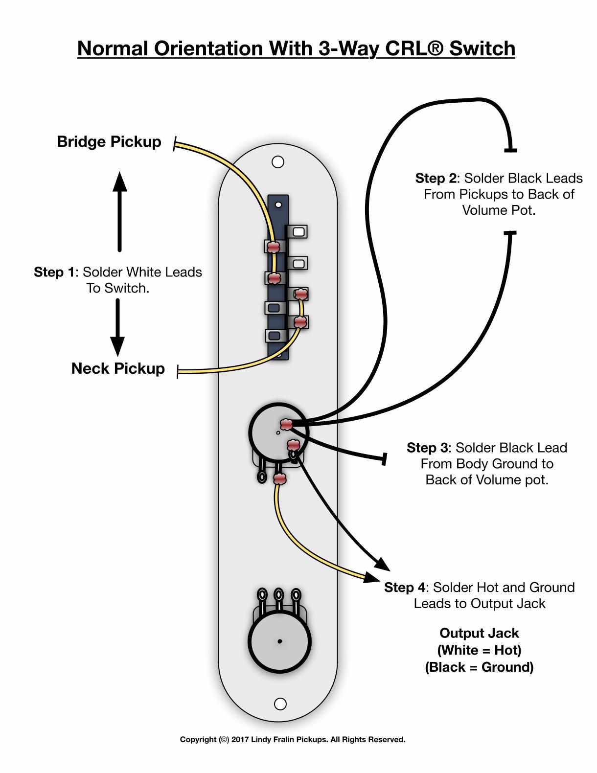
Normal Orientation With 3-Way CRL® Switch
Bridge Pickup
Neck Pickup
Output Jack(White = Hot)
(Black = Ground)
Step 1: Solder White LeadsTo Switch.
Step 2: Solder Black LeadsFrom Pickups to Back of
Volume Pot.
Step 3: Solder Black LeadFrom Body Ground to Back of Volume pot.
Step 4: Solder Hot and GroundLeads to Output Jack
Copyright (©) 2017 Lindy Fralin Pickups. All Rights Reserved.

Bridge Pickup
Neck Pickup
Output Jack(White = Hot)
(Black = Ground)
Step 1: Solder White LeadsTo Switch.
Step 3: Solder Black LeadsFrom Tele Neck Cover
& Bridge Pickup Black to Back of Volume Pot.
Step 4: Solder Black LeadFrom Body Ground to Back of Volume pot.
(Usually coming from bridge)
Step 5: Solder Hot and GroundLeads to Output Jack
Step 2: Solder Black LeadFrom Neck Pickup
To Switch.
Normal Orientation With 4-Way Oak® Switch
Copyright (©) 2017 Lindy Fralin Pickups. All Rights Reserved.
Bridge Pickup
Neck Pickup
Output Jack(White = Hot)
(Black = Ground)
Step 1: Solder White LeadsTo Switch.
Step 2: Solder Black LeadsFrom Pickups to Back of
Volume Pot.
Step 3: Solder Black LeadFrom Body Ground to Back of Volume pot.
Step 4: Solder Hot and GroundLeads to Output Jack
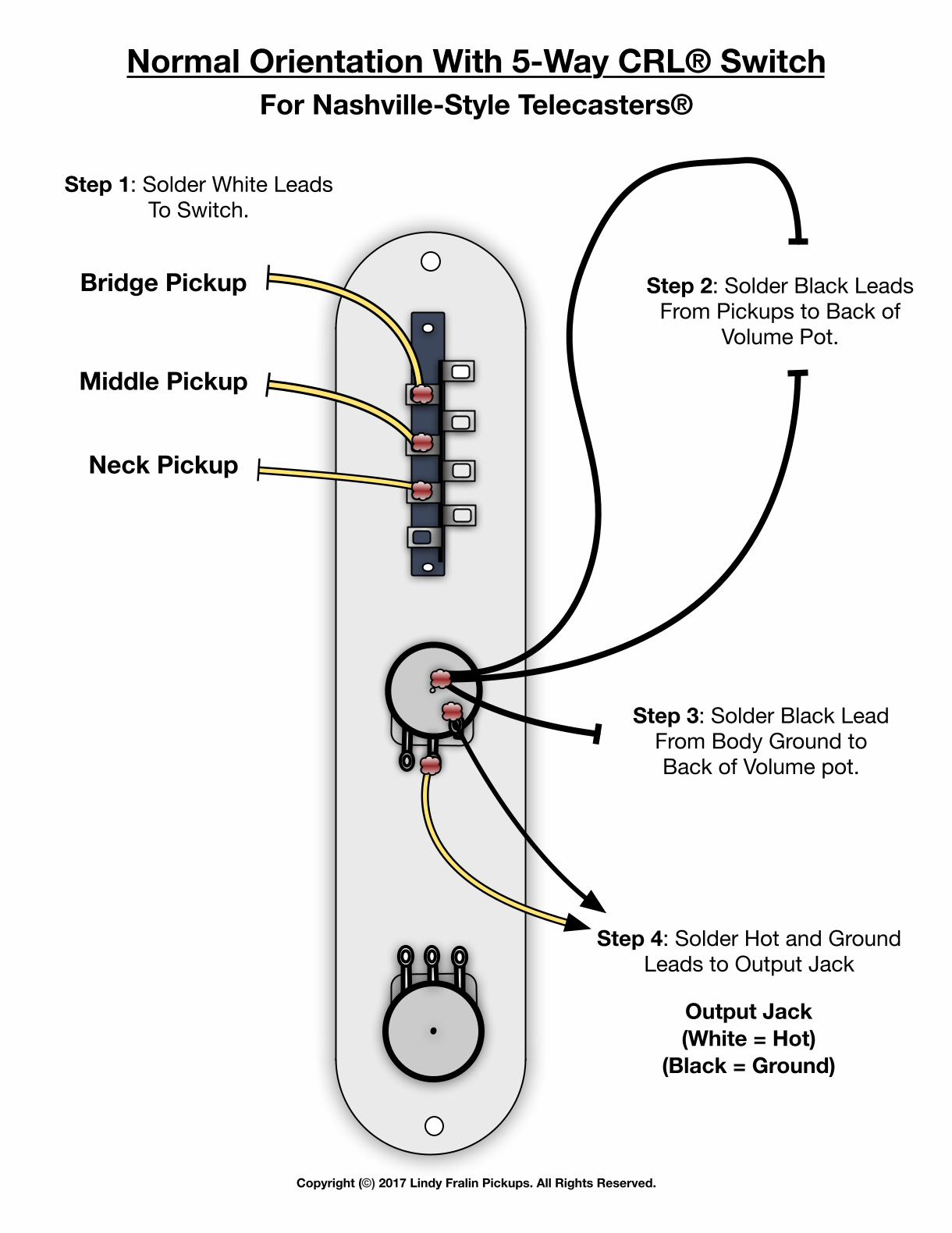
Middle Pickup
Normal Orientation With 5-Way CRL® SwitchFor Nashville-Style Telecasters®
Copyright (©) 2017 Lindy Fralin Pickups. All Rights Reserved.
Bridge Pickup
Neck Pickup
Output Jack(White = Hot)
(Black = Ground)
Step 1: Solder White LeadsTo Switch.
Step 2: Solder Black LeadsFrom Pickups to Back of
Volume Pot.
Step 3: Solder Black LeadFrom Body Ground to Back of Volume pot.
Step 4: Solder Hot and GroundLeads to Output Jack
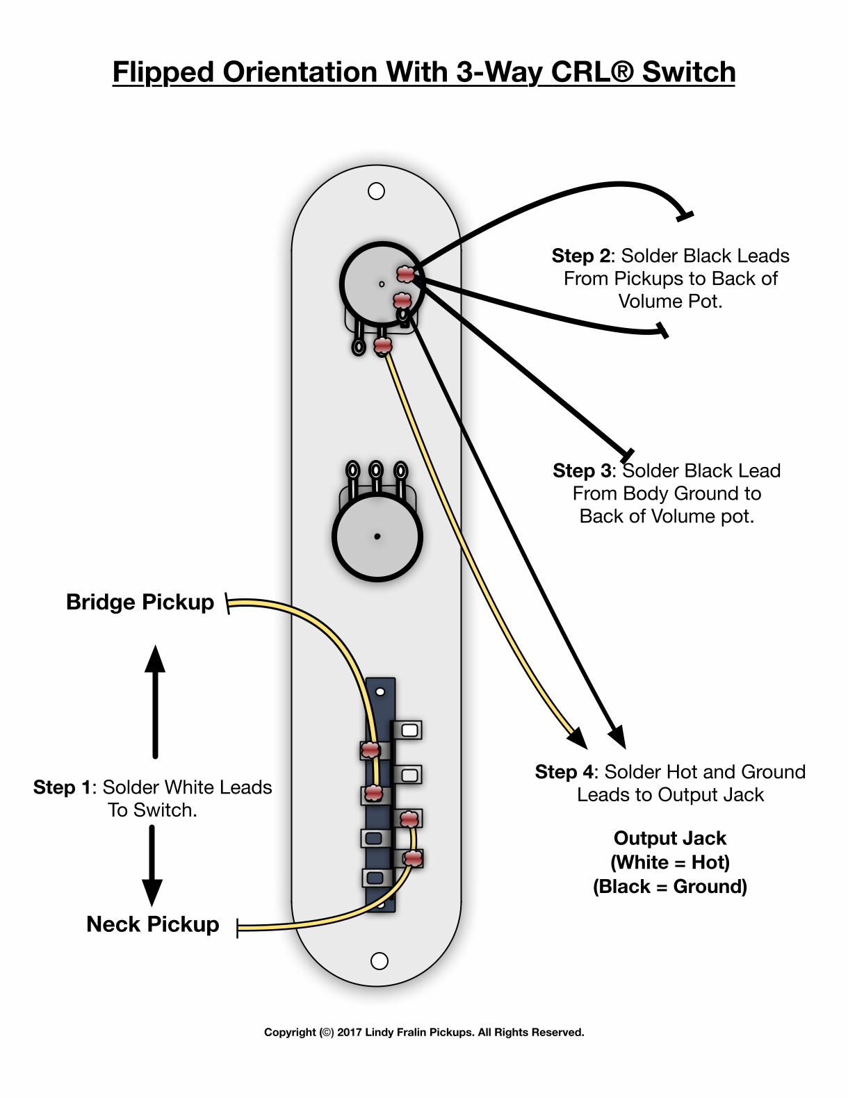
Flipped Orientation With 3-Way CRL® Switch
Copyright (©) 2017 Lindy Fralin Pickups. All Rights Reserved.
Output Jack(White = Hot)
(Black = Ground)
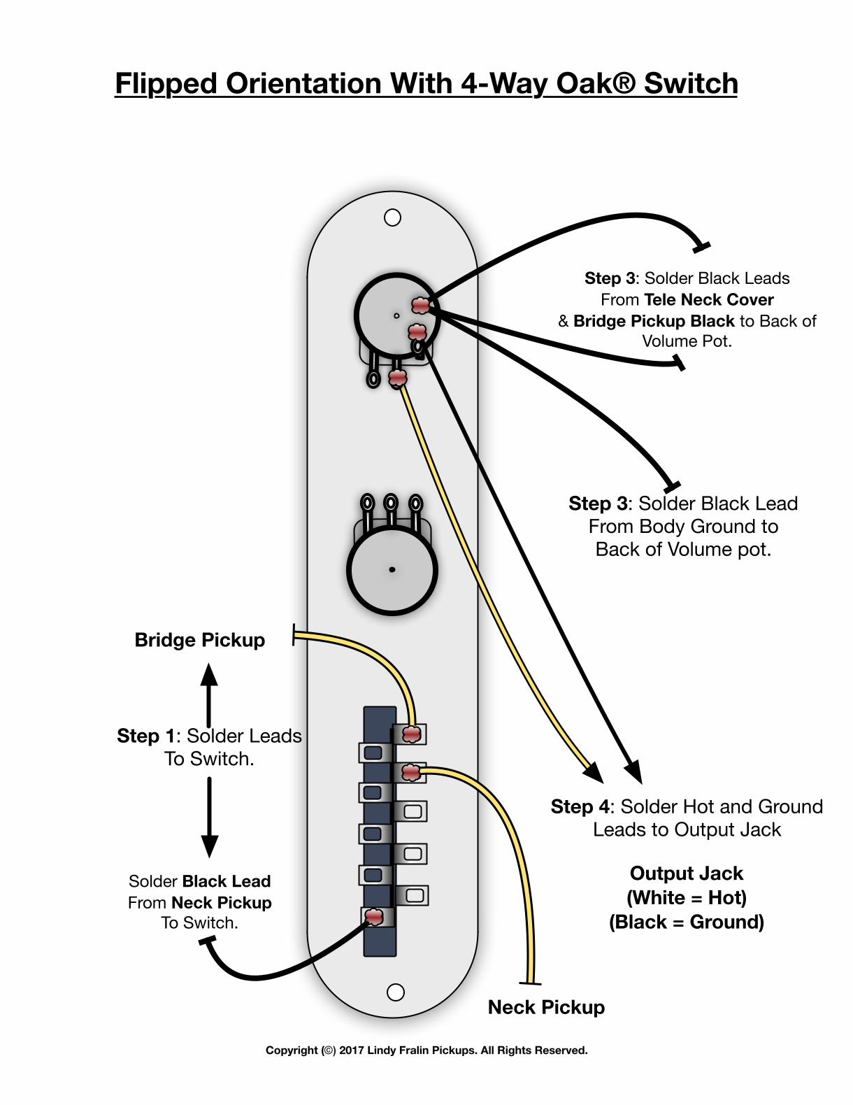
Step 3: Solder Black LeadsFrom Tele Neck Cover
& Bridge Pickup Black to Back of Volume Pot.
Step 3: Solder Black LeadFrom Body Ground to Back of Volume pot.
Step 4: Solder Hot and GroundLeads to Output Jack
Bridge Pickup
Neck Pickup
Step 1: Solder LeadsTo Switch.
Solder Black LeadFrom Neck Pickup
To Switch.
Flipped Orientation With 4-Way Oak® Switch
Copyright (©) 2017 Lindy Fralin Pickups. All Rights Reserved.
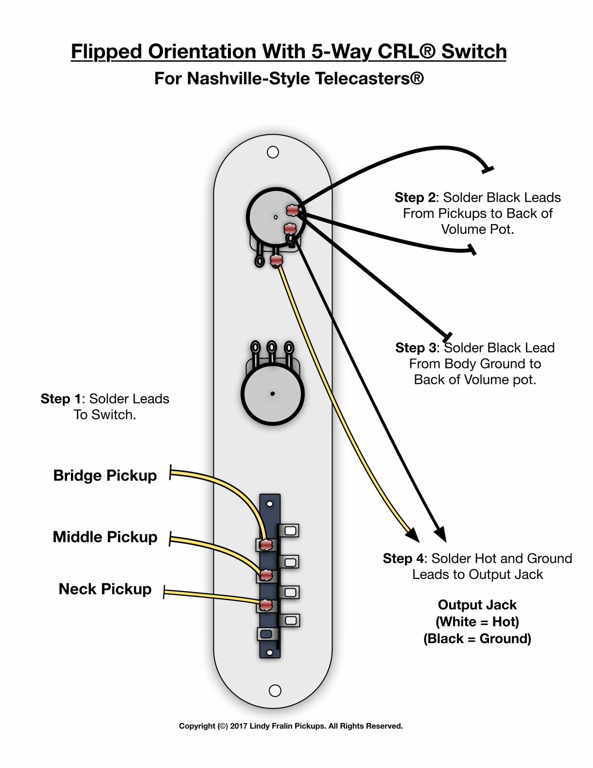
Output Jack(White = Hot)
(Black = Ground)
Step 2: Solder Black LeadsFrom Pickups to Back of
Volume Pot.
Step 3: Solder Black LeadFrom Body Ground to Back of Volume pot.
Step 4: Solder Hot and GroundLeads to Output Jack
Bridge Pickup
Neck Pickup
Middle Pickup
Step 1: Solder LeadsTo Switch.
Flipped Orientation With 5-Way CRL® SwitchFor Nashville-Style Telecasters®
Copyright (©) 2017 Lindy Fralin Pickups. All Rights Reserved.