
TEKNISK RIKTLINJE 2013-02-25 TR01-09E - Svenska … · IEC 62231 Composite station post insulators...
37
Transcript of TEKNISK RIKTLINJE 2013-02-25 TR01-09E - Svenska … · IEC 62231 Composite station post insulators...


TEKNISK RIKTLINJE 2013-02-25 TR01-09E
2/37
TEKNISK RIKTLINJE 2013-02-25 TR01-09E
3/37
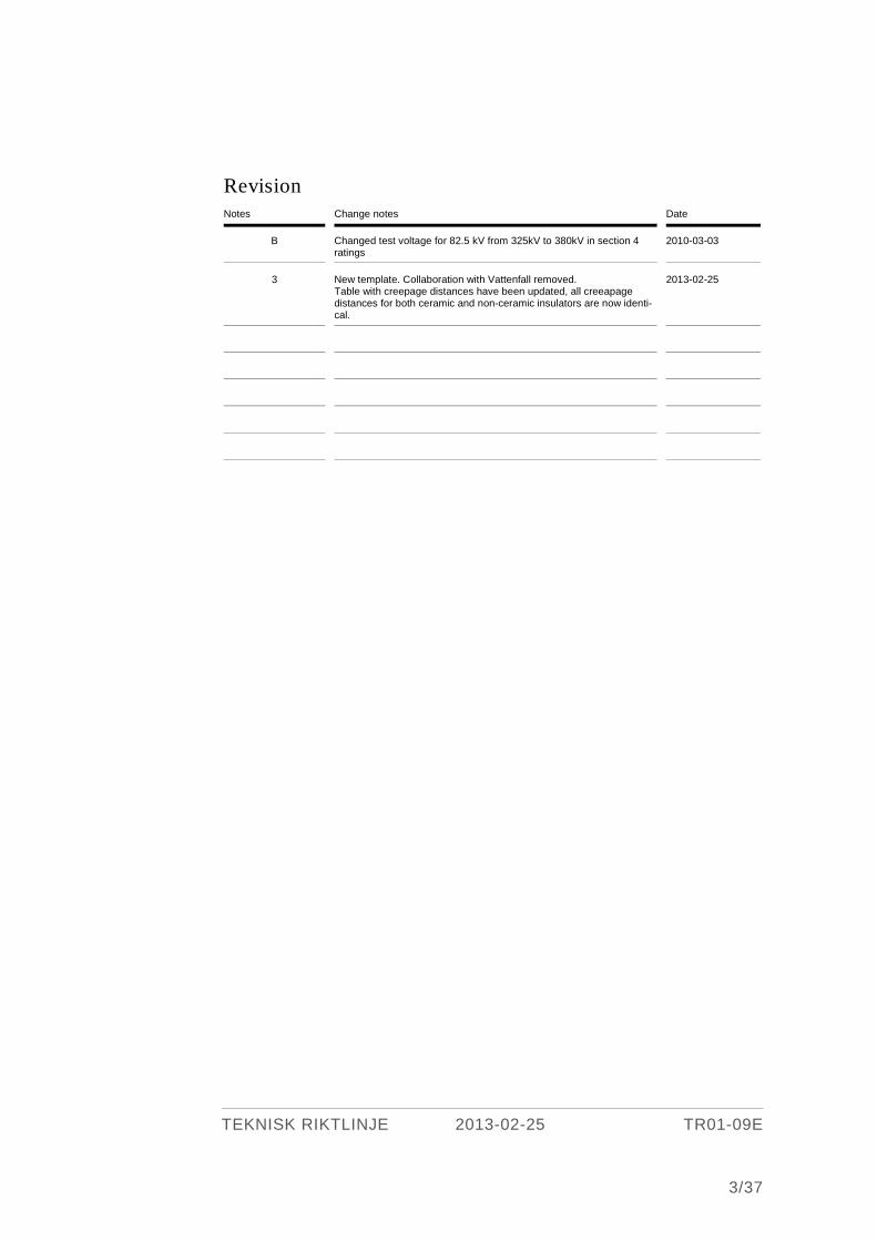
Revision Notes Change notes Date
B Changed test voltage for 82.5 kV from 325kV to 380kV in section 4 ratings
2010-03-03
3 New template. Collaboration with Vattenfall removed. Table with creepage distances have been updated, all creeapage distances for both ceramic and non-ceramic insulators are now identi-cal.
2013-02-25

TEKNISK RIKTLINJE 2013-02-25 TR01-09E
4/37
Content
1 GENERAL .................................................................................................................. 7
1.1 Aplicable standards. .................................................................................... 7
2 SERVICE CONDITIONS .......................................................................................... 8
2.1 Ambient temperature. ................................................................................ 8 2.2 Installation. ................................................................................................. 8 2.3 Ice thickness. ............................................................................................... 8 2.4 Wind pressure. ............................................................................................ 8
3 DEFINITIONS .......................................................................................................... 8
4 RATING ..................................................................................................................... 9
4.1 Rated insulation level .................................................................................. 9 4.2 Rated frequency. ........................................................................................ 10 4.3 Rated current ............................................................................................. 10 4.4 echanical strain. ......................................................................................... 10
4.4.1 Mechanical reliability ................................................................. 10 4.4.2 Mechanical endurance of disconnector ..................................... 10 4.4.3 Electrical endurance of earthing switch .................................... 11
4.5 Inductive and capacitive breaking capacity ............................................ 11 4.6 Performance to break commuting currents ............................................ 11
5 DESIGN OF DISCONNECTOR. ............................................................................. 11
5.1 General ....................................................................................................... 11 5.2 Corrosion protection .................................................................................. 12 5.3 Bearing ....................................................................................................... 12 5.4 Insulators ................................................................................................... 12
5.4.1 Creepage distance ....................................................................... 12 5.5 Current carrying parts .............................................................................. 13 5.6 H.V. Terminals ........................................................................................... 13 5.7 Arrangement .............................................................................................. 14

TEKNISK RIKTLINJE 2013-02-25 TR01-09E
5/37
5.8 Special requirements for earthing switches ............................................ 14 5.8.1 Installation .................................................................................. 15 5.8.2 Equipment for indication and interlocking ............................... 15
5.9 Earthing ...................................................................................................... 15 5.10 Nameplates ................................................................................................. 15
6 GENERAL REQUIREMENTS FOR DESIGN OF MANUAL OPERATED
MECHANISMS, MOTOR OPERATED MECHANISMS AND LINKAGE
SYSTEM. .................................................................................................................. 16
6.1 Mechanical design ..................................................................................... 16 6.1.1 Operation ..................................................................................... 16 6.1.2 Device for blocking and interlocking ......................................... 16 6.1.3 Indication ..................................................................................... 17 6.1.4 Degrees of protection .................................................................. 17
6.2 Electrical design ......................................................................................... 17 6.2.1 General ......................................................................................... 17 6.2.2 Auxiliary equipment for manual operating mechanisms ........ 17 6.2.3 Interlock device ........................................................................... 18 6.2.4 Equipment for motor operated mechanisms ............................ 19
7 LABELING ...............................................................................................................22
7.1 Indications ..................................................................................................22 7.2 Device for selection of operation mode and blocking ..............................22 7.3 Device for manual cancellation of interlocks...........................................22 7.4 Motor-protective circuit-breaker .............................................................22 7.5 Switch for operating circuits ....................................................................22 7.6 Switch for heating circuits ........................................................................23 7.7 Interlock device. .........................................................................................23 7.8 Manual operating device. .........................................................................23
8 INTERLOCKING OF MOTOR-OPERATED MECHANISM, DESIGN AND
FUNCTION ..............................................................................................................23
9 BLOCKING AND LOCKING .................................................................................. 24
9.1 Blocking ..................................................................................................... 24
TEKNISK RIKTLINJE 2013-02-25 TR01-09E
6/37
9.2 Switch for operating circuits ................................................................... 24 9.3 Interlocking device.................................................................................... 24
10 TESTS ...................................................................................................................... 25
10.1 Type tests .................................................................................................... 25 10.1.1 General ......................................................................................... 25 10.1.2 Scope of tests ................................................................................ 25
11 DOCUMENTATION ............................................................................................... 26
11.1 General ...................................................................................................... 26 11.2 Documentation with tender ..................................................................... 26 11.3 Documentation together with apparatus delivery ................................. 26 11.4 Documentation and spares after delivery .............................................. 28 11.5 Documentation and spares after delivery .............................................. 28
12 Appendix ................................................................................................................. 29
12.1 Appendix 1 Terminal Plate och Bolt, dimensions. ................................. 29 12.2 Appendix 2 Padlock................................................................................... 31 12.3 Appendix 3 Design and guarantee data ..................................................32 12.4 Appendix 4 Main terminal movements ...................................................34 12.5 Appendix 5 Component Datalist .............................................................. 35

TEKNISK RIKTLINJE 2013-02-25 TR01-09E
7/37
1 GENERAL
1.1 Aplicable standards. Applicable Swedish Standards are valid. When there is no Swedish Standard, Europe-
an Standard (EN) and IEC Publication shall apply. The latest edition shall apply.
Where voltage transformers offered do not in every way fulfil the stipulated standards
and the additions of the guidelines, deviations shall be specified.
Applicable standards and guidelines:
SS 40103 10 Switchgear, controlgear and fuses - Vocabulary.
SS-EN 60694 Common specifications for high-voltage switchgear and
controlgear standards.
SS-EN 62271-102 High-voltage switchgear and controlgear - Part 102:
- AC disconnectors and earthing switches.
SS-EN 60529 Degrees of protection provided by enclosures (IP code).
SS-EN ISO 1461 Hot dip galvanized coatings on fabricated iron and steel
articles.
SS 3192 Hot dip galvanized threaded pieces of steel.
SS 14 23 03 Stainless steel – SS steel 2303
SS 4210167 Design of outdoor substations - Wind and ice loads.
SS-IEC 60168 Tests on indoor and outdoor post insulators of ceramic
material or glass for systems with nominal voltages
greater than 1000 V
SS-IEC 273 Characteristics of indoor and outdoor post insulators
for systems with nominal voltages greater than 1000 V.
SS-EN 60437 Radio interference test on H.V. insulators
SS-EN 60507 Artificial pollution tests on H.V. insulators to be used
on a.c. systems
TEKNISK RIKTLINJE 2013-02-25 TR01-09E
8/37
IEC 62231 Composite station post insulators for substations with
a.c. voltages greater than 1000 V up to 245 kV –
Definitions, test methods and acceptance criteria.
2 SERVICE CONDITIONS
2.1 Ambient temperature. The lowest ambient temperature shall be -50° C.
2.2 Installation. At installation in dirty and/or salty environment reinforced requirements for corrosion
protection, wash ability and creep distance of insulators will be specified. See also item
5.2 and 5.4.
2.3 Ice thickness. Ice thickness class 20 mm shall apply.
2.4 Wind pressure. For normal applications the wind pressure 700 Pa against a plane surface shall apply.
For equipment in exposed locations, e.g. coastal or mountain areas, a higher wind
pressure might be necessary. Dimensioning shall then be done with a wind pressure in
accordance with SS 42101 67.
3 DEFINITIONS
Definitions are specified in applicable standards.
Rated voltage The rated voltage indicates the upper limit of the highest voltage of systems for which
the disconnector/earthing switch is intended. (same voltage as the highest voltage for
equipment)
Rated value
A quantity value assigned, generally by the manufacturer, for a specified operating
condition of a component, device or equipment. (IEV 151-04-03)

TEKNISK RIKTLINJE 2013-02-25 TR01-09E
9/37
Nominal voltage of a system A suitable approximate value of voltage used to designate or identify a system.
(IEV 601-01-21)
Highest voltage of equipment The highest r.m.s phase-to-phase voltage for which the equipment is designed in re-
spect of its insulation as well as other characteristics which relate to this voltage in the
relevant equipment standards. (IEV 604-03-01).
4 RATING
4.1 Rated insulation level The following values of insulation level should be used:
Nominal Rated Rated lightning impulse Rated 1 min power frequency voltage voltage withstand voltage withstand voltage
kV (rms) kV (peak) kV (r.m.s)
To earth and between poles
Across the insulating distance
To earth and between poles
Across the insu-lating distance
10 12 75 85 28 32
20 24 125 145 50 60 30 36 170 195 70 80 45 52 250 290 95 110 70 82.5 380 440 150 175 132 145 650 750 275 315 150 170 650 750 275 315 220 245 950 1050 395 460
Nominal Voltage
Rated voltage
kV (r.m.s)
Rated lightning withstand voltage
kV (peak)
Rated switching impulse withstand voltage kV (peak)
Rated short-duration Power frequency- withstand voltage
kV (r.m.s.)
phase to earth
across isolat-ing distance
phase to earth
across iso-lating dis-
tance
phase to earth
across isolating distance
380 420 1425 1425 (+240) 1050 900 (+345) 520 610
TEKNISK RIKTLINJE 2013-02-25 TR01-09E
10/37
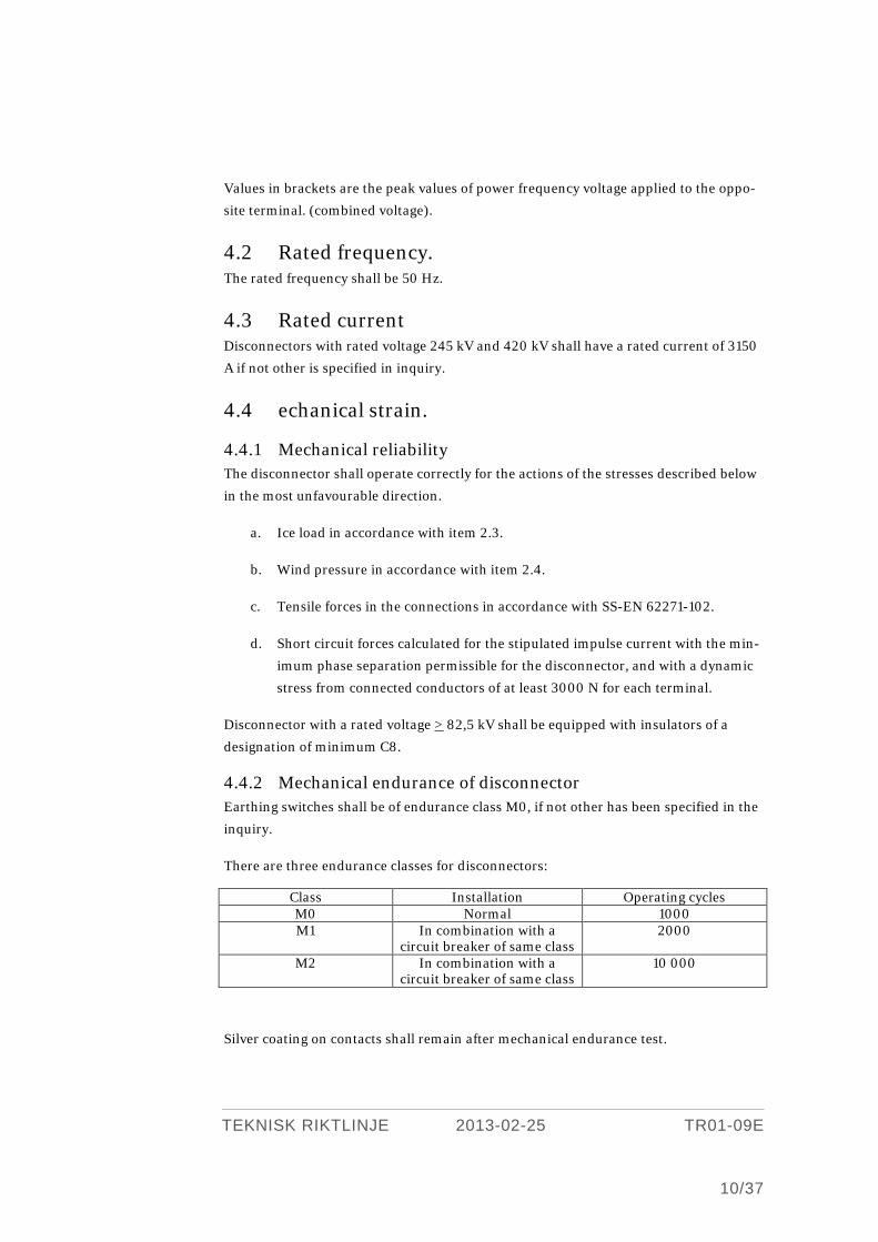
Values in brackets are the peak values of power frequency voltage applied to the oppo-
site terminal. (combined voltage).
4.2 Rated frequency. The rated frequency shall be 50 Hz.
4.3 Rated current Disconnectors with rated voltage 245 kV and 420 kV shall have a rated current of 3150
A if not other is specified in inquiry.
4.4 echanical strain.
4.4.1 Mechanical reliability The disconnector shall operate correctly for the actions of the stresses described below
in the most unfavourable direction.
a. Ice load in accordance with item 2.3.
b. Wind pressure in accordance with item 2.4.
c. Tensile forces in the connections in accordance with SS-EN 62271-102.
d. Short circuit forces calculated for the stipulated impulse current with the min-
imum phase separation permissible for the disconnector, and with a dynamic
stress from connected conductors of at least 3000 N for each terminal.
Disconnector with a rated voltage > 82,5 kV shall be equipped with insulators of a
designation of minimum C8.
4.4.2 Mechanical endurance of disconnector Earthing switches shall be of endurance class M0, if not other has been specified in the
inquiry.
There are three endurance classes for disconnectors:
Class Installation Operating cycles M0 Normal 1000 M1 In combination with a
circuit breaker of same class 2000
M2 In combination with a circuit breaker of same class
10 000
Silver coating on contacts shall remain after mechanical endurance test.

TEKNISK RIKTLINJE 2013-02-25 TR01-09E
11/37
4.4.3 Electrical endurance of earthing switch Earthing switches shall be of endurance class E0, if not other has been specified in the
inquiry.
There are three endurance classes for earthing switches:
Class Type Closing against short-circuit
E0 No closing capability 0 E1 Closing capability 2 E2 Closing capability 5
4.5 Inductive and capacitive breaking capacity In the enquiry it shall be specified if the disconnector shall be used for sections. SS-EN
62271-102 is applicable.
If earthing switches for voltage > 52 kV shall be used for earthing the end of parallel
lines, the class shall be specified in the inquiry. There are two classes, class A and B,
where class A is used for relatively short lines or where the parallelism is short and
class B is used for long lines and where the parallelism is long.
SS-EN 62271-102 is applicable.
4.6 Performance to break commuting currents In the enquiry it shall be specified if the disconnector shall switch commuting current.
SS-EN 62271-102 is applicable.
5 DESIGN OF DISCONNECTOR.
5.1 General Type of disconnector shall be specified in the inquiry. Disconnectors for rated voltages
above 170 kV shall have fixed terminals. In the delivery shall be included all parts nec-
essary for erection of the fully operational disconnector on the structures provided by
the purchaser, fulfilling the ratings for a new apparatus in accordance to the instruc-
tions for condition control. Products necessary for the erection shall be included in the
delivery, such as lubricants, contact grease.
Type of operation mode , manual or motor, shall be specified by the purchaser.The
supplier shall specify all possible locations for the operating mechanism. In addition it
shall be specified whether it is optional to which side disconnector with lateral move-
ment can be opened. Free space needed around the disconnector and operating mech-

TEKNISK RIKTLINJE 2013-02-25 TR01-09E
12/37
anism for locking, manual operation and service shall be clearly marked at the dimen-
sion drawing.
Disconnectors shall be designed so as to prevent the ingress of water which can cause
damage or jamming owing to freezing.
5.2 Corrosion protection External parts shall be made of corrosion-resistant material. Steel shall be corrosion
free or protected by hot-dip galvanizing (SS-EN ISO 1461). Worked surfaces may be
protected in an other permanent way.
When disconnectors are placed in corrosive atmosphere a reinforced corrosion protec-
tion may be applied. This will then be specified in the inquiry.
5.3 Bearing Bearings shall preferably be so designed that lubrication is not necessary. Where such
bearing-designs cannot be applied, the bearings shall be designed for greasing and
provided with hydraulic grease nipples. Grease nipples located on earthed parts should
be accessible when the disconnector is in service.
5.4 Insulators Insutators can be of porceline or composit type. Insulators shall be in accordance with
IEC 60815 and other applicable standards.
In polluted atmosphere insulators shall have increased creep distance. Increased creep
distance if required shall be specified in the inquiry. The normal and extened creepage
distances are specified in Table § 5.4.1.
Disconnectors can be washable or non washable. Washability shall be specified in the
inquiry. If the disconnector is washable with limitation the supplier shall specify the
limitation in the tender.
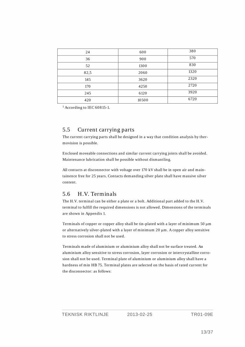
5.4.1 Creepage distance The requirements for insulator creepage distances are summarised in the table below:
Highest voltage for equipment,
Um [kV]
Min. creepage distance [mm]
Ceramic and composite
Polluted atmosphere (class d)1
Normal atmosphere (class b)1
12 300 190
TEKNISK RIKTLINJE 2013-02-25 TR01-09E
13/37
24 600 380
36 900 570
52 1300 830
82,5 2060 1320
145 3620 2320
170 4250 2720
245 6120 3920
420 10500 6720
1 According to IEC 60815-1.
5.5 Current carrying parts The current carrying parts shall be designed in a way that condition analysis by ther-
movision is possible.
Enclosed moveable connections and similar current carrying joints shall be avoided.
Maintenance lubrication shall be possible without dismantling.
All contacts at disconnector with voltage over 170 kV shall be in open air and main-
tainence free for 25 years. Contacts demanding silver plate shall have massive silver
content.
5.6 H.V. Terminals The H.V. terminal can be either a plate or a bolt. Additional part added to the H.V.
terminal to fulfill the required dimensions is not allowed. Dimensions of the terminals
are shown in Appendix 1.
Terminals of copper or copper alloy shall be tin-plated with a layer of minimum 50 µm
or alternatively silver-plated with a layer of minimum 20 µm. A copper alloy sensitive
to stress corrosion shall not be used.
Terminals made of aluminium or aluminium alloy shall not be surface treated. An
aluminium alloy sensitive to stress corrosion, layer corrosion or intercrystalline corro-
sion shall not be used. Terminal plate of aluminium or aluminium alloy shall have a
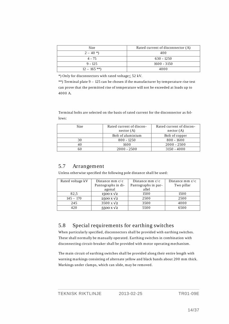
hardness of min HB 75. Terminal plates are selected on the basis of rated current for
the disconnector: as follows:
TEKNISK RIKTLINJE 2013-02-25 TR01-09E
14/37
Size Rated current of disconnector (A) 2 – 40 *) 400
4 - 75 630 - 1250 9 - 125 1600 - 3150
12 – 165 **) 4000
*) Only for disconnectors with rated voltage< 52 kV.
**) Terminal plate 9 – 125 can be chosen if the manufacturer by temperature rise test
can prove that the permitted rise of temperature will not be exceeded at loads up to
4000 A.
Terminal bolts are selected on the basis of rated current for the disconnector as fol-
lows:
Size Rated current of discon-nector (A)
Rated current of discon-nector (A)
Bolt of aluminium Bolt of copper 30 800 - 1250 800 - 1600 40 1600 2000 - 2500 60 2000 - 2500 3150 - 4000
5.7 Arrangement Unless otherwise specified the following pole distance shall be used:
Rated voltage kV Distance mm c/c Pantographs in di-
agonal
Distance mm c/c Pantographs in par-
allel
Distance mm c/c Two pillar
82,5 1500 x √2 1500 1500 145 – 170 2500 x √2 2500 2500
245 3500 x √2 3500 4000 420 5500 x √2 5500 6500
5.8 Special requirements for earthing switches When particularly specified, disconnectors shall be provided with earthing switches.
These shall normally be manually operated. Earthing switches in combination with
disconnecting circuit-breaker shall be provided with motor operating mechanism.
The main circuit of earthing switches shall be provided along their entire length with
warning markings consisting of alternate yellow and black bands about 200 mm thick.
Markings under clamps, which can slide, may be removed.

TEKNISK RIKTLINJE 2013-02-25 TR01-09E
15/37
5.8.1 Installation Earthing switches shall be possible to erect in one of the following alternatives:
> At the disconnector or at other apparatus.
> At existing post insulator. It is preferred that the installation can be performed
without dismantling of the existing equipment.
> At insulator belonging to earthing switch.
5.8.2 Equipment for indication and interlocking When particularly specified, earthing switches shall be provided with
> Auxiliary contacts.
> Interlocking devices.
> Mechanical interlocks towards disconnector.
If operation of the disconnector when its earthing switch is closed causes damage to
the disconnector, the motor operation of the disconnector shall be blocked by electrical
interlocks controlled by the earthing switch.
5.9 Earthing The earthing terminal shall be designed for cable lugs with two holes.
Flexible earthing connections shall be arranged to exclude corrosion, wear damage or
burning due to contact to other material.
5.10 Nameplates Nameplates shall be on Swedish.
Disconnectors consisting of independent or separate delivered poles or with removable
operating mechanism shall be equipped with nameplates marking unique serial num-
bers for every pole and operating mechanism. Current carrying parts shall be durable
marked to be related to nameplate of respective pole.
TEKNISK RIKTLINJE 2013-02-25 TR01-09E
16/37
6 GENERAL REQUIREMENTS FOR DE-SIGN OF MANUAL OPERATED MECHANISMS, MOTOR OPERATED MECHANISMS AND LINKAGE SYS-TEM.
6.1 Mechanical design
6.1.1 Operation It shall be possible to operate single-pole or multi-pole disconnectors with the operat-
ing mechanism.
The motor operated mechanism shall be provided with a manual operating device. The
device for manual operation (handle, hand crank etc.) shall be on suitable height above
ground, roughly 1.2 m.
The operating mechanism shall be provided with a device for choice between manual
or motor operation. This device shall be lockable in the required position. Regarding
locking device, see point 9.
Motor-driven operating mechanisms, linkage system and current carrying parts shall
mechanically be capable of withstanding the operating forces necessary to safely com-
plete an operation with a disconnector stressed with forces in accordance with clause
4.4.1. The torque developed by the operating mechanism shall either be limited to this
level, or else tests shall show that both disconnector and linkage system can withstand
the maximum torque of the operating mechanism. Safety margins and tolerances of
the torque-limiting device shall be taken into consideration.
Absent function from end-position contacts may not result in damage to the discon-
nector or end-stop.
Current curves for opening and closing a new disconnector shall be provided.
6.1.2 Device for blocking and interlocking Of safety reasons the operating mechanism and disconnector shall be possible to block
from leaving the closed or open position. With blocking means labeling and locking of
a direct-acting mechanical and electrical blocking device. Regards blocking see clause
9.

TEKNISK RIKTLINJE 2013-02-25 TR01-09E
17/37
When specified in the order, the operating mechanism shall be provided with an inter-
lock device, see clause 8.
6.1.3 Indication The open and closed positions of the disconnector shall be indicated mechanically on
the operating mechanism, linkage system or pole.
6.1.4 Degrees of protection The operating mechanism shall be enclosed in a case with at least protective class
IP 54 in accordance to SS-EN 60529. When a washable design is required the protec-
tive class shall be at least IP 55.
An enclosure for operating mechanism, auxiliary contacts or interlock device shall be
ventilated and the ventilation openings shall be covered with fine-mesh wire netting or
similar.
6.2 Electrical design
6.2.1 General Control and motor circuits shall be designed for DC, 110 V or 220 V.
Heating circuits shall be designed for 230 V, 50 Hz.
The DC equipment shall be designed for 2-pole control of control and motor circuits.
Auxiliary contacts shall be easily accessible for connection, inspection and adjustment.
Components shall be provided with special markings for identification on electrical
circuit diagrams.
Terminals shall be clearly and durable marked.
Connecting cables inside the operating mechanism shall be clearly and durably
marked at both ends.
Contact parts and screws shall be corrosion-resistant.
6.2.2 Auxiliary equipment for manual operating mechanisms On request manual operating mechanism for disconnector or earthing switch for rated
voltage 82 ,5 kV shall be p rovided or afterwards be possible to com plete with 6 sin-
gle-pole auxiliary contacts. Manual operating mechanism for disconnector or earthing
switch > 82,5 kV shall be provided with 6 single-pole auxiliary contacts. The auxiliary
contacts shall have the functions defined below:
TEKNISK RIKTLINJE 2013-02-25 TR01-09E
18/37
For indication of the disconnector or earthing switch state:
> 1 closed contact for open disconnector.
> 1 closed contact for closed disconnector.
For interlock, etc:
> 1 closed contact for open disconnector.
> 1 closed contact for closed disconnector.
> 1 open contact for open disconnector.
> 1 open contact for closed disconnector.
The changeover of auxiliary contacts from one position to the other shall occur, with a
margin, between the point where the end-position fixation comes into play and the end
position.
Breaking and making current for auxiliary contacts shall in accordance with SS-EN
60694
be at least 2 A at 220 V d.c. with a current-time constant of at least 20 ms.
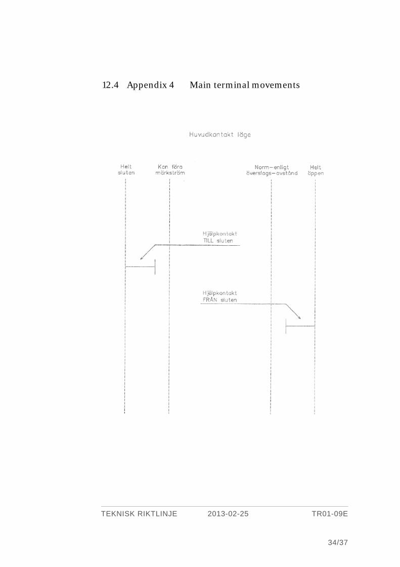
Contact-movement diagrams for disconnecter and auxiliary contacts shall be given.
From the diagram the safety margins in operational force of the auxiliary contacts shall
be evident.
6.2.3 Interlock device On request, the operating mechanism shall be provided and afterwards be possible to
complete with an interlock device designed to interlock the disconnector in both open
and closed position. If the disconnector is supplied with both auxiliary contacts in
accordance to clause 6.2.2 and an interlock device in accordance to clause 6.2.3, these
can preferable be placed in the same casing.
Interlock devices shall without sustaining damage be able to withstand the
stresses arising when attempting to operate the disconnecter with forces in accordance
with clause 6.1.1.
TEKNISK RIKTLINJE 2013-02-25 TR01-09E
19/37
Interlock-coil with its mechanism shall have service reliability always with correct
function. Safety margins in operational force and path of travel shall be specified.
The interlock shall be removed when the coil of the interlock device is connected, e.g
the disconnector shall be possible to operate by the manual operating mechanism.
When the coil of the interlock device is disconnected and the disconnector is in a posi-
tion between end-positions, the interlock shall not be activated before the disconnector
has reached an end-position.
It shall be possible to cancel the interlock manually. Device for canceling shall only be
possible to operate after removal of a protective hood by tool or that the device is
locked without hindering the electrical function.
The interlock device shall be fitted with an auxiliary contact, made for closing optional-
ly in interlocked or in not interlocked position. The contact should be mechanically
operated (forced motion) by the interlock coil.
The interlock device shall correctly operate between 85 % and 110 % of rated voltage.
The device shall be dimensioned for constant connection and manage this at 110 % of
the rated voltage. The power consumption shall be given by the manufacturer.
6.2.4 Equipment for motor operated mechanisms
6.2.4.1 Function The electrical connections shall be so arranged, that started operations are completed
irrespective of the duration of the operating impulse. Operation shall start after an
impulse > 50 ms.
A no-voltage relay shall break the self-holding action of the operating circuit if the
motor voltage is lost.
6.2.4.2 Motor The motor may be dimensioned for intermittent operation.
Motors shall be protected against switching over-voltages caused by operating mecha-
nism auxiliaries. The voltage amplitude must not exceed 50 % of the r.m.s. value of the
insulation level.
6.2.4.3 Motor-protective circuit-breaker Motor-protective circuit-breakers shall have two-pole contact function and manual
make and break ought to be possible.
TEKNISK RIKTLINJE 2013-02-25 TR01-09E
20/37
When manual breaking is not possible, a two-pole switch shall be used. This shall have
the necessary making and breaking capacities for the fully braked motor.
The manufacturer shall specify the minimum useful and the maximum allowed fuse
size for the feeder.
6.2.4.4 Fuse Short-circuit protection in the operating mechanism is not required.
6.2.4.5 End-position contacts The end-position function shall bring about two-pole switching in and out the motor.
Data for the end-position contacts shall be chosen taking into consideration whether
the motor is controlled directly or via contactors. For direct control, the end-position
contact shall be capable of making and breaking a fully braked motor.
Contact-movement diagrams and safety margins in operational force and path of trav-
el shall be presented.
6.2.4.6 Contactor Contactors shall be dimensioned for switching in and out a fully braked motor.
6.2.4.7 Auxiliary contacts Operating mechanisms shall be provided with 8 single-pole auxiliary contacts with the
functions specified below. The changeover of auxiliary contacts from one position to
the other shall occur, with a margin, between the point where the end-position fixation
comes into play and the end position.
For indication of the disconnector state:
> 2 closed contacts for open disconnector,open for intermediate and closed position.
> 2 closed contacts for closed diconnector, open for intermediate and open position
For interlocking, indications etc.:
> 2 open contacts for open disconnector, closed for intermediate and closed posi-
tion.
> 2 open contacts for closed disconnector, closed for intermediate and open posi-
tion.
Breaking and making current for auxiliary contacts shall in accordance with SS-EN
60694 be at least 2 A at 220 V d.c. with a current-time constant of at least 20 ms.
Contact-movement diagrams and safety margins in operational path of travel shall be
provided.
TEKNISK RIKTLINJE 2013-02-25 TR01-09E
21/37
6.2.4.8 Interlock coils Coils for interlock devices in accordance with clause 8.
If interlock coils, with regard to the function of the operating mechanism, require aux-
iliary contacts, these shall have data in accordance with clause 6.2.4.7.
6.2.4.9 No-voltage relay Instantaneous non-measuring relay with trip setting at max.65 % of rated voltage for
constantly connection and max. ambient temperature.
6.2.4.10 Switch for operating voltage The switch shall have the positions TILL (ON) and FRÅN (OFF) and have contacts for
two-pole breaking of control and holding circuits.
The switch may be combined with the selection device for selection between manual
and motor operation in accordance with clause 6.1.1 and/or with the device for locking
the disconnector in accordance with clause 6.1.2.
6.2.4.11 Auxiliary contact for locking device etc. See point 9. Contact data, see clause 6.2.4.7.
6.2.4.12 Heating equipment Operating mechanisms shall be provided with constant basic heating to achieve venti-
lation.
If additional heating is needed for guaranteed function within the specified tempera-
ture range, this shall be controlled by a thermostat. A low heat power rating is consid-
ered an advantage. Additional heating shall be supervised by a device having contact
function for signal.
There shall be a switch provided with contacts for two-pole breaking of the heating
circuits.
Any heaters shall be touch-protected and easily exchangeable.
6.2.4.13 Terminal blocks The number of terminal blocks shall be chosen so that at least all external control cir-
cuits and contacts in accordance with 6.2.2, 6.2.3 and 6.2.4 can be connected to termi-
nal blocks. Incoming wires shall be connected to one side of the row of terminal blocks
and internal wires to the other. A maximum of two wires shall be connected to each
block terminal.
Terminal blocks shall be easily accessible. The blocks shall be provided with provision
for disconnection, but this shall only be possible with tools. The terminal blocks shall
be designed for the connection of wires with area of 1-10 mm² and be provided with
terminals suitable for connection with test plugs with Ø 4 mm.
TEKNISK RIKTLINJE 2013-02-25 TR01-09E
22/37
Terminal blocks for motor feeding shall be designed for the connection of wires with
area up to 16 mm². The terminal blocks shall be connected in series with 10 mm² ter-
minal blocks if they are not disconnectable.
Terminal blocks for internal circuits may be chosen by the manufacturer.
7 LABELING
7.1 Indications Position indication in accordance to point 6.1.3 shall have the following wording and
colours:
> Symbol for Open position ( O ) in white on green background.
> Symbol for Closed position ( I ) in black on yellow background.
7.2 Device for selection of operation mode and blocking The device for selection of operation mode in the motor operating mechanism and the
position of locking in open or closed positions shall be labeled with the following word-
ing:
HANDMANÖVER (i.e. locking position manual operation)
MOTORMANÖVER (i.e. locking position motor operation)
ÖPPEN (i.e. locking position open)
SLUTEN (i.e. locking position closed)
7.3 Device for manual cancellation of interlocks The device for manual cancellation of interlocks shall be labeled in accordance with
clause 7.7.
7.4 Motor-protective circuit-breaker The motor-protective circuit-breaker in accordance with clause 6.2.4.3 shall be provid-
ed with the symbols O and I and a label with the word: MOTOR.
7.5 Switch for operating circuits The switch for operating voltage in accordance with clause 6.2.4.10 shall be provided
with the symbols O and I and a label with the word: MANÖVERSPÄNNING.
TEKNISK RIKTLINJE 2013-02-25 TR01-09E
23/37
7.6 Switch for heating circuits The switch for heating in accordance with clause 6.2.4.12 shall be provided with the
symbols O and I and a label with the word: VÄRME.
7.7 Interlock device. Where an interlock device in accordance with clause 8 is provided, it shall be supplied
with the following labels:
One label adjacent to the device for manual cancellation of interlocks with the word-
ing: MANUELL UPPHÄVNING AV FÖRREGLING (i.e. manual cancellation of inter-
lock).
One label for the interlocked position with the word: FÖRREGLING (i.e. interlock).
7.8 Manual operating device. Labels for indication of operating direction shall have symbols showing the direction.
8 INTERLOCKING OF MOTOR-OPERATED MECHANISM, DESIGN AND FUNCTION
On request the operating mechanism shall be provided with an interlock mechanism.
The interlock mechanisms shall without sustaining damage be able to withstand the
stresses arising when attempting to operate the disconnector with forces in accordance
with point 6.1.1. The interlock mechanism must not block due to external forces from
wind, ice, short-circuit, or any influence other than from the operating equipment.
Safety margins in operational force and path of travel shall be specified.
The interlock mechanism shall be electrically controlled and switched in only during
the operating cycle. When under voltage the interlock shall be cancelled, and in the
dead state the interlock shall be engaged.
An electrical or manual operation started shall always be completed, even if the inter-
lock mechanism looses its voltage during the operating cycle.
It shall be possible to cancel the interlock manually, although only with a special device
which shall be lockable in the position FÖRREGLING (interlock), without hindering

TEKNISK RIKTLINJE 2013-02-25 TR01-09E
24/37
the electrical function. This locking requirement is fulfilled if the device is placed un-
der a separate lockable cover.
The interlock device shall automatically return to the position FÖRREGLING. The
device or its cover shall be labeled with words in according with point 7.7.
9 BLOCKING AND LOCKING
9.1 Blocking It shall be possible to block the disconnector. With blocking means that all operating
(electrically an manually) of and external influence to the disconnector shall be hin-
dered to bring the disconnector out of open or closed positions and that:
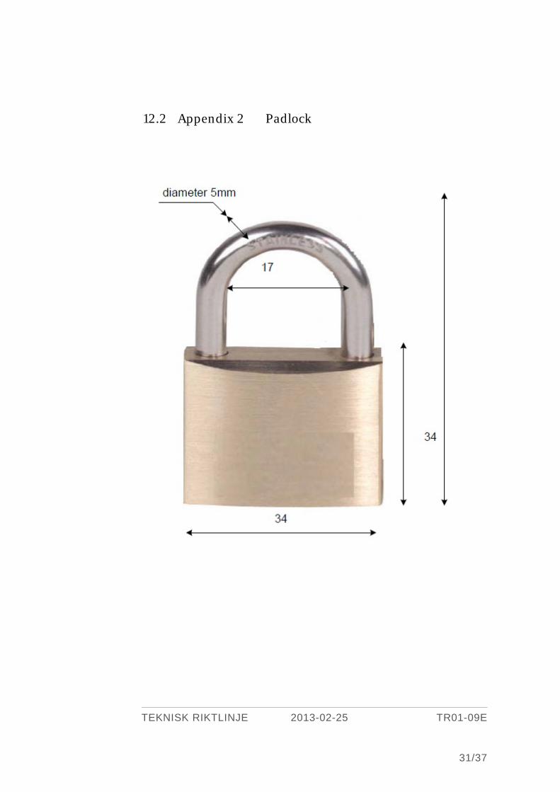
> A separate padlock can be used to lock the position.
> A separate label can be attached to the padlock.
The primary obstruction shall work as a direct mechanical obstruction.
The safety of the obstruction may not be influenced by the dimension of the padlock.
The motor and operation circuits shall be opened in both poles.
Locking shall be carried out with padlocks in accordance with appendix 2.
The locking device shall be easily accessible and placed or protected for easy handling
during the winter.
The locking position shall be labeled in accordance with point 7.2.
9.2 Switch for operating circuits The operating mechanism shall be provided with a lockable switch for selecting manu-
al or motor operation. In locked position only the selected function shall be possible.
When selecting the manual operating position, motor and operating circuits shall be
automatically opened in both poles.
9.3 Interlocking device Locking of interlock device, see clause 6.1.2
TEKNISK RIKTLINJE 2013-02-25 TR01-09E
25/37
10 TESTS
10.1 Type tests
10.1.1 General The disconnector, linkage system and operating mechanism shall be tested connected
together as a unit. Type tests shall have been performed on disconnector, linkage sys-
tem and operating mechanism of the same design as those included in the delivery.
10.1.2 Scope of tests Besides compulsory tests in accordance with SS-EN 62271-102 the following tests shall
be done:
> Operation under severe ice conditions. (20 mm).
> Operation at minimum and maximum ambient temperature.
> Verification of the proper function of the position indicating device.
> Prove the short-circuit making performance of earthing switches type E1 and E2
(if applicable).
> Bus-transfer current switching test on disconnector (if applicable).
> Induced current switching test (on earthing switches used at parallel lines, if ap-
plicable).
10.1.2.1 Temperature-rise tests of the main circuit. In order to provide the best possible base for condition analysis with a thermo-vision
camera, the temperature rise should be specified for load currents corresponding to
30, 60 and 100 % of the rated current. The measuring points shall be selected and
performed regards thermo-graphing. Tolerances in temperature rise with respect to
normal ageing should be provided. Values for 30 and 60 % of rated current may be
calculated.
10.1.2.2 Measurement of the resistance of the main circuit. Partial resistances and the distribution between parallel current paths shall be meas-
ured.
10.1.2.3 Operation under severe ice conditions. Testing with 20 mm ice layer is required. During the tests the motor current shall be
registered.

TEKNISK RIKTLINJE 2013-02-25 TR01-09E
26/37
11 DOCUMENTATION
11.1 General Final instructions, dimension drawings and electrical circuit and schematic diagrams
shall be written in Swedish.
11.2 Documentation with tender With the tender the following documents shall be provided:
> List of data, dimension drawings, electrical circuit and schematic diagrams, in-
structions for erection, operation and maintenance, type test certificates and also
other documents needed for the technical evaluation.
> Bases for evaluation of the need and costs for maintenance, such as:
• The interval for condition control and other measures of maintenance and the
time necessary for these works.
• Necessary spares, special tools and accessories and the costs for these.
> Environmental information as below (see also TR 13-01):
• The interval for condition control and other measures of maintenance and the
time necessary for these works.
• Information about the main content of the equipment (type of material in per-
centage of weight) Information about the content of dangerous substances
(for example heavy metals, carcinogenic compounds and compounds hard to
biodegrade, xenobiotic substances).
• Handling and treating of the equipment when it has served its time.
11.3 Documentation together with apparatus delivery In connection with the apparatus delivery the following documents shall be delivered
electronically and in one paper copy, if not others have been agreed:
A list (disconnector chart) including:
> Purchasing and order number.
> Manufacturer.
> Type.
> Serial number.
> Rated data.
TEKNISK RIKTLINJE 2013-02-25 TR01-09E
27/37
> Type test certificates.
> Verification (title and number) of the following documents which shall be deliv-
ered together with the list:
> Assembly drawings and drawing lists.
> Instructions for transport, storing, erection, service, testing, condition control and
adjustment.
> Lubrication chart.
> List of lubrication and contact grease.
> List of other chemical products for erection and maintenance.
> List of products and protective information for all listed chemical products.
> List of special tools and accessories for erection and maintenance.
> List of equipment for testing and condition control.
> List of spares.
> List of material for repair.
> 9 copies of final dimension drawings.
> 9 copies of final electrical circuit and schematic diagrams.
> Routine test certificates.
> Filled in Component data list according to Appendix 5.
To the actual delivery exactly defined bases for the purchaser's maintenance work shall
be delivered. The technical documentation shall make it possible to organize own spare
and service organisation. The documentation shall also be possible to use for education
of organizers and workmen in store and for maintenance. The documentation shall
include instructions for condition control and make valuating, preparing and realizing
of necessary maintenance work possible, taking into account the purchaser's own aim
and judging of the risk. In the list (disconnector chart) assembly drawings or bases
valid for actual disconnector shall be specified. Details and valid bases for a specified
disconnector or series of disconnectors of the same type shall be possible to identify
through the list (disconnector chart). This means that valid edition of documents shall
be clearly marked in the list.
It shall be possible to identify standard mechanical elements for purchase in Swedish
commercial outlets. See also SS-EN 60694.
TEKNISK RIKTLINJE 2013-02-25 TR01-09E
28/37
At the first delivery all documents specified in the list (disconnector chart) and possi-
ble to copy, shall be delivered put together in one file as base for the purchaser's
maintenance handbook. For succeeding deliveries changed drawings and instructions
possible to copy shall be delivered.
11.4 Documentation and spares after delivery The manufacturer shall at request provide the purchaser with necessary service bulle-
tins and during at least ten years after delivery with for the maintenance necessary
spares. Improvements in design, or instructions which can be applied to the equip-
ment as supplied, shall be notified after delivery, preferably in the form of service bul-
letins. See also SS-EN 60694.
11.5 Documentation and spares after delivery The manufacturer shall at request provide the purchaser with necessary service bulle-
tins and during at least ten years after delivery with for the maintenance necessary
spares. Improvements in design, or instructions which can be applied to the equip-
ment as supplied, shall be notified after delivery, preferably in the form of service bul-
letins. See also SS-EN 60694.
TEKNISK RIKTLINJE 2013-02-25 TR01-09E
29/37
12 Appendix
12.1 Appendix 1 Terminal Plate och Bolt, dimensions.

TEKNISK RIKTLINJE 2013-02-25 TR01-09E
30/37
Bolt Length 125 mm : Diameter : 30, 40, 60 mm
Plate Figur
Measure
(mm): a b c d e
2 - 75 1 2-hål 75 17,5 40 14 10
4 - 75 2 4-hål 75 17,5 40 14 15
9 - 125 3 9-hål 125 22,5 40 14 35
12 - 165 4 12-hål 125 22,5 40 14 35
TEKNISK RIKTLINJE 2013-02-25 TR01-09E
31/37
12.2 Appendix 2 Padlock

TEKNISK RIKTLINJE 2013-02-25 TR01-09E
32/37
12.3 Appendix 3 Design and guarantee data
Mode:
> Pantograph in diagonal erection.
> Pantograph in parallel erection.
> Centre-brake disconnector.
> Three-pillar type.
Earthing switches:
> Built on: 0, 1 or 2.
> Free erected earthing switches: Yes or No.
> Interlock device.
> Mechanical interlock towards disconnector.
Operating mechanisms
> Per 3 poles: 1 or 3 S.
Type of operating mechanism:
> Motor operating mechanism.
> Manual operating mechanism with 6 auxiliary contacts.
> Manual operating mechanism without auxiliary contacts.
Counter contact for pantograph:
> Material of busbar tube: Al (or Cu).
> Outer diameter of tube: 100, 150 or 250 mm.
Service condition:
> Air pollution: normal or salt or industry.
> Corrosion protection: normal or increased (requirement shall be specified).
TEKNISK RIKTLINJE 2013-02-25 TR01-09E
33/37
> Washabillity: washable or not washable.
> Creep distance: normal (28 mm/kV) or increased (44 mm/kV).
> Protective class: IP54 or IP55.
Rated voltage: 12, 24, 36, 52, 82.5, 145, 170, 245, 420 kV
Insulation level: Values in clause 4.1.
> 1 min., 50Hz to earth,between poles and across open pole.
> Lightning impulse to earth, between poles and across open pole.
> Switching impulse to earth and across open pole.
Rated frequence: 50 Hz.
Rated current: 630, 800, 1250, 1600, 2000, 2500, 3150, 4000 A.
Rated short time current: 12.5, 16, 20, 25, 31.5, 40, 50 kA.
Rated peak withstand current: 32, 40, 50, 63, 80, 100, 125 kA peak.
Rated time for short-circuit: 1 s (0,5 s).
Voltage for motor and control circuits: 110 or 220 V dc.
Rated voltage for heating: 230 V, 50 Hz.
Inductive breaking capacity: If other values than 1A for rated voltage 170 kV, 0,5 A
> 170 kV.
Capacitive breaking capacity: If other values than 1A for rated voltage 170 kV, 0,5 A
> 170 kV.
Breaking of commuting current: Yes or No.
Mechanical endurance: If other than Class M0.
Electrical endurance (earthing switches): If other than Class E0.
TEKNISK RIKTLINJE 2013-02-25 TR01-09E
34/37
12.4 Appendix 4 Main terminal movements

TEKNISK RIKTLINJE 2013-02-25 TR01-09E
35/37
12.5 Appendix 5 Component Datalist
Indatablad för frånskiljare och jordningskopplare Svenska Kraftnät
Beskrivning Värde Enhet Not
Allmänt
Station * Ifylls av ställverksbyggaren
EX Hagby
Objekt id/Littera * Ifylls av ställverksbyggaren
EX CL6 S5-F1
Beskrivning * Frånskiljare
/Jordningskopplare
Inköpsnummer *
Leverantörens ordernummer *
Tillverkare *
Typbeteckning *
Levererad * ååmm
Utförandeform *
Märkspänning kV
Märkström A
Märkkorttidsström kA
Tid s
Stötström kA
Isolationsnivå till jord - kort stöt kV
Isolationsnivå till jord - lång stöt kV
Isolationsnivå till jord - 50Hz 1
kV
Isolationsnivå över pol - kort stöt kV
Isolationsnivå över pol - lång stöt kV
Isolationsnivå över pol - 50Hz 1
kV
Spolbarhet * Ja/Nej/Begränsad
Brytförmåga kap A
Brytförmåga ind A
Slutningstid s
Öppningstid s
Minsta polavstånd mm
Vikt per trepolig apparat kg
Pris per trepolig apparat SEK
TEKNISK RIKTLINJE 2013-02-25 TR01-09E
36/37
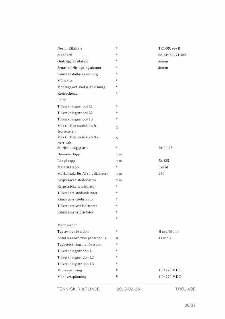
Norm, Riktlinje * TR1-09, rev B
Standard * SS-EN 62271-102
Ombyggnadsdatum * ååmm
Senaste drifttagningsdatum * ååmm
Sammanställningsritning *
Måttskiss *
Montage och skötselanvisning *
Kretsschema *
Poler
Tillverkningsnr pol L1 *
Tillverkningsnr pol L2 *
Tillverkningsnr pol L3 *
Max tillåten statisk kraft -
horisontalt N
Max tillåten statisk kraft -
vertikalt N
Storlek uttagsplatta * Ex 9-125
Diameter tapp mm
Längd tapp mm Ex 125
Material tapp * Cu/Al
Motkontakt för Al-rör, diameter mm 250
Krypsträcka stödisolator mm
Krypsträcka vridisolator *
Tillverkare stödisolatorer *
Ritningsnr stödisolator *
Tillverkare vridisolatorer *
Ritningsnr vridisolator *
*
Manöverdon
Typ av manöverdon * Hand/Motor
Antal manöverdon per trepolig
st 1 eller 3
Typbeteckning manöverdon *
Tillverkningsnr don L1 *
Tillverkningsnr don L2 *
Tillverkningsnr don L3 *
Motorspänning V 110/220 V DC
Manöverspänning V 110/220 V DC
TEKNISK RIKTLINJE 2013-02-25 TR01-09E
37/37
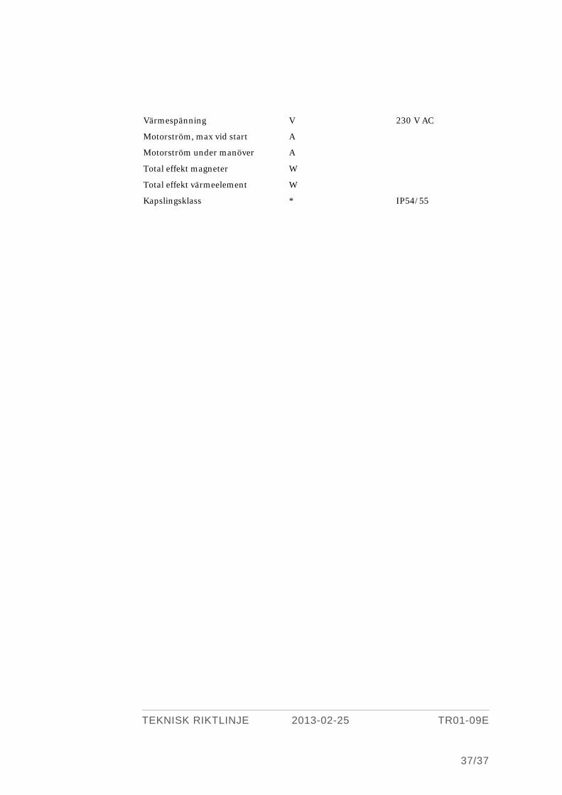
Värmespänning V 230 V AC
Motorström, max vid start A
Motorström under manöver A
Total effekt magneter W
Total effekt värmeelement W
Kapslingsklass * IP54/55