Tekla Structure System_Tutorial
500
Tekla Structures System Manual Product version 14.0 April 2008 © 2008 Tekla Corporation www.cadfamily.com EMail:[email protected] The document is for study only,if tort to your rights,please inform us,we will delete
Transcript of Tekla Structure System_Tutorial

Tekla StructuresSystem Manual
Product version 14.0April 2008
© 2008 Tekla Corporation
www.cadfamily.com EMail:[email protected] document is for study only,if tort to your rights,please inform us,we will delete

© 2008 Tekla Corporation and its licensors. All rights reserved.
This Software Manual has been developed for use with the referenced Software. Use of the Software, and use of this Software Manual are governed by a License Agreement. Among other provisions, the License Agreement sets certain warranties for the Software and this Manual, disclaims other warranties, limits recoverable damages, defines permitted uses of the Software, and determines whether you are an authorized user of the Software. Please refer to the License Agreement for important obligations and applicable limitations and restrictions on your rights.
In addition, this Software Manual is protected by copyright law and by international treaties. Unauthorized reproduction, display, modification, or distribution of this Manual, or any portion of it, may result in severe civil and criminal penalties, and will be prosecuted to the full extent permitted by law.
Tekla, Tekla Structures, Xcity, Xengineer, Xpipe, Xpower, Xsteel, and Xstreet are either registered trademarks or trademarks of Tekla Corporation in the European Union, the United States, and/or other countries. Other product and company names mentioned in this Manual are or may be trademarks of their respective owners. By referring to a third-party product or brand, Tekla does not intend to suggest an affiliation with or endorsement by such third party and disclaims any such affiliation or endorsement, except where otherwise expressly stated.
Portions of this software:
D-Cubed 2D DCM © 2008 Siemens Product Lifecycle Management Software III (GB) Ltd.
EPM toolkit © 1995-2004 EPM Technology a.s., Oslo, Norway. All rights reserved.
XML parser © 1999 The Apache Software Foundation. All rights reserved.
Project Data Control Library © 2006 - 2007 DlhSoft. All rights reserved.
DWGdirect, DGNdirect and OpenDWG Toolkit/Viewkit libraries © 1998-2005 Open Design Alliance. All rights reserved.
FLEXnet Copyright © 2006 Macrovision Corporation and/or Macrovision Europe Ltd. All Rights Reserved. This product contains proprietary and confidential technology provided by and owned by Macrovision Europe Ltd., UK, and Macrovision Corporation of Santa Clara, California, U.S.A. Any use, copying, publication, distribution, display, modification, or transmission of such technology in whole or in part in any form or by any means without the prior express written permission of Macrovision Europe Ltd. and Macrovision Corporation is strictly prohibited. Except where expressly provided by Macrovision Europe Ltd. and Macrovision Corporation in writing, possession of this technology shall not be construed to confer any license or rights under any of Macrovision Europe Ltd. and Macrovision Corporation’s intellectual property rights, whether by estoppel, implication, or otherwise.
Elements of the software described in this Manual may be the subject of pending patent applications in the European Union and/or other countries.
www.cadfamily.com EMail:[email protected] document is for study only,if tort to your rights,please inform us,we will delete

TEKLA STRUCTURES 14.0 3
Contents
Preface .............................................................................................................37Audience ........................................................................................................................................................... 37Additional help resources .................................................................................................................................. 37Conventions used in this guide ......................................................................................................................... 38Related guides .................................................................................................................................................. 39
1 Using Tekla Structures effectively......................................................... 411.1 General ................................................................................................................................................. 41
Firm and project folders ................................................................................................................... 42Numbering series ............................................................................................................................. 42Phases ............................................................................................................................................. 42Catalogs ........................................................................................................................................... 42Preferences...................................................................................................................................... 43
Profile names ............................................................................................................................ 43Connections .............................................................................................................................. 43Edge distance ............................................................................................................................ 43
Recording and running macros ........................................................................................................ 44Warning messages .......................................................................................................................... 45
1.2 Modeling ............................................................................................................................................... 45Automating the detailing process ..................................................................................................... 45Predefining part properties............................................................................................................... 46
Using predefined properties ...................................................................................................... 46Modeling tools .................................................................................................................................. 46AutoDefaults..................................................................................................................................... 47AutoConnection................................................................................................................................ 47
1.3 Drawings and printers........................................................................................................................... 47Drawing properties ........................................................................................................................... 48Layouts and templates ..................................................................................................................... 48Reports and symbols ....................................................................................................................... 48Selection filters................................................................................................................................. 48Wizards ............................................................................................................................................ 48Defining print devices....................................................................................................................... 48
1.4 Autosave............................................................................................................................................... 48Setting Autosave interval ................................................................................................................. 49
www.cadfamily.com EMail:[email protected] document is for study only,if tort to your rights,please inform us,we will delete

4 TEKLA STRUCTURES 14.0
Autosave file location ....................................................................................................................... 49Keeping Autosave files..................................................................................................................... 50Usernames ....................................................................................................................................... 50Application error ............................................................................................................................... 50
Fatal: Model memory corrupted by read. ................................................................................... 501.5 Customizing the interface...................................................................................................................... 51
Toolbars ........................................................................................................................................... 51Managing toolbars ..................................................................................................................... 51Icons .......................................................................................................................................... 52
Creating a user-defined toolbar ........................................................................................................ 52Creating a user-defined menu.......................................................................................................... 53Defining shortcuts............................................................................................................................. 53
1.6 Optimizing system performance............................................................................................................ 54Virtual memory ................................................................................................................................. 54Display adaptor ................................................................................................................................ 54Solid buffer size................................................................................................................................ 55How Tekla Structures handles solids ............................................................................................... 55
2 Multi-user mode....................................................................................... 572.1 Multi-user mode .................................................................................................................................... 57
When to use multi-user mode .......................................................................................................... 58Switching between single-user and multi-user modes ............................................................... 58
Overview of the multi-user system ................................................................................................... 59The Tekla Structures server ..................................................................................................... 59
How multi-user works ....................................................................................................................... 60Locking ...................................................................................................................................... 60
Setting up the multi-user system ...................................................................................................... 61Saving in multi-user mode................................................................................................................ 62
Save ........................................................................................................................................... 62Autosave .................................................................................................................................... 62
Saving model revision comments..................................................................................................... 63Shutting down the model.................................................................................................................. 64Copying multi-user models............................................................................................................... 64Displaying active multi-users ............................................................................................................ 64Clearing locks................................................................................................................................... 65Error messages ................................................................................................................................ 65Recommendations ........................................................................................................................... 66
Server computer ........................................................................................................................ 66Client computer .......................................................................................................................... 66Network ...................................................................................................................................... 67Model dump ............................................................................................................................... 67
2.2 Modeling in multi-user mode................................................................................................................. 67
www.cadfamily.com EMail:[email protected] document is for study only,if tort to your rights,please inform us,we will delete

TEKLA STRUCTURES 14.0 5
Working with a master model........................................................................................................... 67Numbering setup.............................................................................................................................. 71Numbering – specific cases ............................................................................................................. 72
2.3 Drawings in multi-user mode ................................................................................................................ 73About drawing files........................................................................................................................... 73Guidelines for multi-user drawings................................................................................................... 73Locks for drawings ........................................................................................................................... 74
2.4 Maintenance procedures ...................................................................................................................... 74Checking multi-user databases........................................................................................................ 75Deleting unnecessary dg files .......................................................................................................... 75
2.5 Access rights ........................................................................................................................................ 75Locking objects ................................................................................................................................ 76Controlling access to attributes ........................................................................................................ 76Restricting access to model ............................................................................................................. 77Controlling access to numbering setup ............................................................................................ 78
3 Files and Folders ..................................................................................... 793.1 Initialization files.................................................................................................................................... 79
About variables ................................................................................................................................ 80Setting variables ........................................................................................................................ 80Using the Advanced Options dialog box ................................................................................... 80Editing the user.ini file ............................................................................................................... 80Disabling variables in an initialization file .................................................................................. 81
Structure........................................................................................................................................... 81Initialization file reading order .................................................................................................... 82Creating customized initialization files ....................................................................................... 83Including other initialization files ................................................................................................ 83
Creating shortcuts ............................................................................................................................ 833.2 File types and function.......................................................................................................................... 85
Input files.......................................................................................................................................... 85Component description files ...................................................................................................... 86
Data files .......................................................................................................................................... 86Data files and modeling tools .................................................................................................... 87
DSTV connection properties ............................................................................................................ 89Messages......................................................................................................................................... 89Profiles ............................................................................................................................................. 90
inp (ASCII) ................................................................................................................................. 90cnv (ASCII) ................................................................................................................................ 90lis (ASCII) .................................................................................................................................. 90Binary files ................................................................................................................................. 90
Bin .................................................................................................................................................... 91
www.cadfamily.com EMail:[email protected] document is for study only,if tort to your rights,please inform us,we will delete

6 TEKLA STRUCTURES 14.0
Fonts ................................................................................................................................................ 91Symbols............................................................................................................................................ 91System ............................................................................................................................................. 92
rpt ............................................................................................................................................... 92tpl ............................................................................................................................................... 92lay .............................................................................................................................................. 92plotdev.bin ................................................................................................................................. 92Wizard files (dproc) .................................................................................................................... 92
3.3 Folders .................................................................................................................................................. 92Folder structure ................................................................................................................................ 93Folder search order .......................................................................................................................... 94Model folder...................................................................................................................................... 95
Saved attributes ......................................................................................................................... 95System folder ................................................................................................................................... 96Project and firm folders .................................................................................................................... 96
Project folder .............................................................................................................................. 97Firm folder .................................................................................................................................. 97
Template folder ................................................................................................................................ 973.4 Customizing Tekla Structures ............................................................................................................... 98
Adding properties ............................................................................................................................. 98Changing user-defined fields ..................................................................................................... 99User-defined fields in templates .............................................................................................. 100Effect on numbering ................................................................................................................. 101
Interpreting objects.inp ................................................................................................................... 101Fields in objects.inp ................................................................................................................. 102
Customizing message files............................................................................................................. 102Changing the language of the user interface ................................................................................. 103Customizing parametric profiles ..................................................................................................... 104
Interpreting profitab.inp ............................................................................................................ 104Save defaults.................................................................................................................................. 105
Creating standard files ............................................................................................................. 106Customizing other files ............................................................................................................ 106
Creating AutoDrawings wizard files................................................................................................ 106Unfolding parameters ..................................................................................................................... 107Using flat bars ................................................................................................................................ 108
Defining flat bar sizes with fltprops.inp .................................................................................... 109Using market sizes ......................................................................................................................... 109
Defining market sizes with marketsize.dat ............................................................................... 110Example ................................................................................................................................... 110
3.5 Log files............................................................................................................................................... 110Tekla Structures log files ................................................................................................................ 110Numbering history log .................................................................................................................... 111
www.cadfamily.com EMail:[email protected] document is for study only,if tort to your rights,please inform us,we will delete

TEKLA STRUCTURES 14.0 7
Interpreting numbering.history ................................................................................................. 112Overlapping part/assembly series ........................................................................................... 113
Drawing history log......................................................................................................................... 113AutoDrawings Wizard log............................................................................................................... 113Viewing log files ............................................................................................................................. 114Direct access to parts from log files ............................................................................................... 114
Access part pop-up menu ....................................................................................................... 114
4 Catalogs ................................................................................................. 1154.1 Things you should know ..................................................................................................................... 115
Open a model first.......................................................................................................................... 116The filter ......................................................................................................................................... 116Saving a modified catalog .............................................................................................................. 116What is the difference between Update and OK?.......................................................................... 117
4.2 The profile catalog .............................................................................................................................. 117Working with rules.......................................................................................................................... 118
Defining the material of profiles ............................................................................................... 119Adding a rule ........................................................................................................................... 121Adding a next level rule ........................................................................................................... 121Editing a rule ........................................................................................................................... 121Organizing rules ...................................................................................................................... 121Deleting a rule ......................................................................................................................... 121
Viewing or modifying the profile catalog......................................................................................... 122Adding a profile .............................................................................................................................. 122
Copy an existing profile ........................................................................................................... 122Creating a new standard profile .............................................................................................. 123
Creating a cross section................................................................................................................. 123Cross section with no inner contours ....................................................................................... 123Cross section with inner contours ............................................................................................ 123
Modifying a cross section............................................................................................................... 124Different types of chamfer ....................................................................................................... 124
Deleting a cross section ................................................................................................................. 125Adding a standard (fixed) user-defined profile ............................................................................... 125Adding user-defined attributes to a profile ..................................................................................... 127Merging profile catalogs ................................................................................................................. 128Exporting the profile catalog........................................................................................................... 128Exporting elements from the profile catalog................................................................................... 128Importing from previous versions ................................................................................................... 129Importing the profile catalog........................................................................................................... 129
What happens to existing profiles? ......................................................................................... 129User-defined fixed cross section definitions ............................................................................ 130User-defined attributes ............................................................................................................ 130
www.cadfamily.com EMail:[email protected] document is for study only,if tort to your rights,please inform us,we will delete

8 TEKLA STRUCTURES 14.0
4.3 The material catalog............................................................................................................................ 130Viewing or modifying the material catalog...................................................................................... 130Adding a user-defined attribute to a material grade ....................................................................... 131
Units of measure ...................................................................................................................... 132Adding a material type.................................................................................................................... 132Adding a new material grade.......................................................................................................... 132Deleting a material grade ............................................................................................................... 133Defining your own symbols for materials........................................................................................ 133Export and import ........................................................................................................................... 134
4.4 The bolt and bolt assembly catalogs................................................................................................... 134Viewing or modifying the bolt catalog............................................................................................. 135Saving a modified bolt catalog ....................................................................................................... 137Viewing or modifying bolt assemblies ............................................................................................ 137Creating studs ................................................................................................................................ 139Merging bolt catalogs ..................................................................................................................... 141Exporting the bolt catalog............................................................................................................... 141Importing the bolt catalog ............................................................................................................... 141
Upgrading to a new version ..................................................................................................... 1414.5 The reinforcing bar catalog ................................................................................................................. 1424.6 For the advanced user ........................................................................................................................ 143
A closer look at the export file ........................................................................................................ 143Do’s & don’ts of editing the export file ............................................................................................ 144Importing part of the bolt catalog.................................................................................................... 144Units used in export and import...................................................................................................... 145Bolt length calculation .................................................................................................................... 146
5 AutoConnection .................................................................................... 1515.1 AutoConnection setup......................................................................................................................... 151
AutoConnection setup .................................................................................................................... 152AutoConnection rule groups........................................................................................................... 153AutoConnection rule sets ............................................................................................................... 153Rules.zxt ........................................................................................................................................ 155Changing a connection................................................................................................................... 155
5.2 AutoDefaults setup.............................................................................................................................. 155AutoDefaults setup ......................................................................................................................... 156Connection properties files............................................................................................................. 157
Saving connection properties .................................................................................................. 157Access to properties files ......................................................................................................... 157
Defaults.zxt..................................................................................................................................... 158Priority of rule sets.......................................................................................................................... 158Editing connection properties ......................................................................................................... 158
www.cadfamily.com EMail:[email protected] document is for study only,if tort to your rights,please inform us,we will delete

TEKLA STRUCTURES 14.0 9
5.3 AutoConnection and AutoDefaults rules............................................................................................. 159Combining and iterating properties ................................................................................................ 161
Limitations ............................................................................................................................... 162Combining properties ..................................................................................................................... 162Iteration with connection check ...................................................................................................... 163Reaction forces and UDL............................................................................................................... 165
6 CNC......................................................................................................... 1676.1 NC files ............................................................................................................................................... 167
Setting up NC files ......................................................................................................................... 168Defining destination machines for parts ......................................................................................... 170Defining selection criteria ............................................................................................................... 170
Maximum size ......................................................................................................................... 171Profile type .............................................................................................................................. 171Maximum size of holes ............................................................................................................ 172
Defining hole properties ................................................................................................................. 172Creating NC files ............................................................................................................................ 172Defining the output format and folder............................................................................................. 173
6.2 DSTV .................................................................................................................................................. 174Fittings affect NC data.................................................................................................................... 174
6.3 DXF..................................................................................................................................................... 175Converting DSTV files to DXF ....................................................................................................... 176
6.4 Peddimat............................................................................................................................................. 176Creating NC files in Peddimat format............................................................................................. 176Output formats for Peddimat .......................................................................................................... 177Defining Peddimat standard tooling ............................................................................................... 177
6.5 Pop-marks ......................................................................................................................................... 178Creating pop-marks........................................................................................................................ 178Pop-mark settings .......................................................................................................................... 179
Pop-marking options ............................................................................................................... 1806.6 Hard stamps ....................................................................................................................................... 181
Creating hard stamps..................................................................................................................... 181Hard stamp properties.................................................................................................................... 181
Information contained in hard stamps ..................................................................................... 182Position of hard stamps ........................................................................................................... 182Hard stamps for secondary parts ............................................................................................ 182
6.7 Plate nesting ....................................................................................................................................... 183Creating nesting tasks.................................................................................................................... 183Editing nesting tasks ...................................................................................................................... 183
Task properties ........................................................................................................................ 184
www.cadfamily.com EMail:[email protected] document is for study only,if tort to your rights,please inform us,we will delete

10 TEKLA STRUCTURES 14.0
Defining stocks ............................................................................................................................... 184Stock properties ....................................................................................................................... 185
Nesting tasks.................................................................................................................................. 185Viewing nesting results................................................................................................................... 186
7 Import and export.................................................................................. 1877.1 Import and export basics..................................................................................................................... 187
Using import and export ................................................................................................................. 188Available formats............................................................................................................................ 188
Importing into Tekla Structures ................................................................................................ 188Exporting from Tekla Structures .............................................................................................. 190
7.2 Conversion files................................................................................................................................... 192Converting twin profiles .................................................................................................................. 192Creating conversion files ................................................................................................................ 192Locating conversion files ................................................................................................................ 193Sample conversion files ................................................................................................................. 193Troubleshooting.............................................................................................................................. 193
7.3 Importing models................................................................................................................................. 194Import tools..................................................................................................................................... 194Overview of importing models ........................................................................................................ 195
Finishing the import ................................................................................................................. 195Re-importing a model ..................................................................................................................... 197
Revision control options ........................................................................................................... 197Creating reports of import............................................................................................................... 198Importing DWG/DXF files ............................................................................................................... 199CIS import ...................................................................................................................................... 199CAD import ..................................................................................................................................... 200
CAD specific information ......................................................................................................... 200Creating log files ...................................................................................................................... 200
CAD import file types...................................................................................................................... 200SDNF specific options ............................................................................................................. 201
FEM import ..................................................................................................................................... 202FEM specific information ......................................................................................................... 202FEM import file types ............................................................................................................... 202
DSTV files ...................................................................................................................................... 203About DSTV ............................................................................................................................. 203
STAAD files .................................................................................................................................... 204Stan 3d files.................................................................................................................................... 204Bus import ...................................................................................................................................... 205Yield stress in FEM import ............................................................................................................. 205Model dump import......................................................................................................................... 206ASCII import ................................................................................................................................... 206
www.cadfamily.com EMail:[email protected] document is for study only,if tort to your rights,please inform us,we will delete

TEKLA STRUCTURES 14.0 11
ASCII format description ................................................................................................................ 206Attribute import............................................................................................................................... 211
About input files ....................................................................................................................... 212Example input file for drawings ............................................................................................... 213Example input file for parts ...................................................................................................... 214Data types file .......................................................................................................................... 214
Steelfab import ............................................................................................................................... 215Steelfab specific information ................................................................................................... 215
Fabtrol XML import......................................................................................................................... 215S-Frame import .............................................................................................................................. 216
About S-Frame imports ........................................................................................................... 216MicasPlus import............................................................................................................................ 216
MicasPlus specific information ................................................................................................ 216Eureka LPM import ........................................................................................................................ 216Overview of ELiPLAN import and export........................................................................................ 216
Import ELiPLAN status data .................................................................................................... 2177.4 Exporting files ..................................................................................................................................... 219
Exporting 3D DWG/DXF ............................................................................................................... 219Export as ................................................................................................................................. 220
Exporting 3D DGN ......................................................................................................................... 221Exporting FEM ............................................................................................................................... 222
Combine segments (MicroSAS) .............................................................................................. 222STAAD .................................................................................................................................... 222DSTV ....................................................................................................................................... 223
Exporting CIMsteel......................................................................................................................... 224Analysis model ........................................................................................................................ 224Manufacturing model ............................................................................................................... 226More CIMsteel information ...................................................................................................... 227
Exporting CAD ............................................................................................................................... 229PML ......................................................................................................................................... 230SDNF ....................................................................................................................................... 230XML ......................................................................................................................................... 232PDMS ...................................................................................................................................... 232
Exporting MIS................................................................................................................................. 233MIS types ................................................................................................................................ 233MIS list file ............................................................................................................................... 234
Exporting ASCII.............................................................................................................................. 234Exporting IFC ................................................................................................................................. 234Exporting a model dump ................................................................................................................ 237Exporting BVBS ............................................................................................................................. 238
Exporting reinforcement to BVBS format ................................................................................. 240Export rebar BVBS (78) dialog box ......................................................................................... 240BVBS (78) specification ........................................................................................................... 242
www.cadfamily.com EMail:[email protected] document is for study only,if tort to your rights,please inform us,we will delete

12 TEKLA STRUCTURES 14.0
Exporting Unitechnik ...................................................................................................................... 243Exporting cast units to Unitechnik format ................................................................................ 244Unitechnik export reference ..................................................................................................... 247Main ......................................................................................................................................... 248Unitechnik configuration .......................................................................................................... 253TS configuration ....................................................................................................................... 257Reinforcement ......................................................................................................................... 259Data specification .................................................................................................................... 263
Overview of ELiPLAN import and export ........................................................................................ 263Exporting ELiPLAN .................................................................................................................. 264
7.5 Exporting drawings.............................................................................................................................. 266Layers............................................................................................................................................. 266
Advanced line type and layer conversion ................................................................................ 2687.6 Reference models ............................................................................................................................... 271
Using a reference model ................................................................................................................ 271Using several reference models..................................................................................................... 272Updating reference models ............................................................................................................ 273Handling large reference models ................................................................................................... 273Detecting changes in reference models ......................................................................................... 273Reference model objects................................................................................................................ 276
Selecting reference models and reference model objects ....................................................... 276Listing reference models and reference model objects in reports ........................................... 277
Supported DGN objects ................................................................................................................. 2777.7 Tekla WebViewer ................................................................................................................................ 278
Publishing a model as a web page................................................................................................. 278Web templates ............................................................................................................................... 279Emailing WebViewer models.......................................................................................................... 279Receiving WebViewer models........................................................................................................ 279Sending WebViewer links............................................................................................................... 280Handling named views ................................................................................................................... 280Handling clip planes ....................................................................................................................... 281Hiding and showing objects............................................................................................................ 282Full content rendering..................................................................................................................... 282How to move and zoom?................................................................................................................ 282
8 Variables ................................................................................................ 2858.1 List of variables ................................................................................................................................... 285
Categories in the Advanced Options dialog box ............................................................................ 285User variables ................................................................................................................................ 286
8.2 A......................................................................................................................................................... 289XS_AD_CURVED_BEAM_SPLIT_ACCURACY_MM .................................................................... 289
www.cadfamily.com EMail:[email protected] document is for study only,if tort to your rights,please inform us,we will delete

TEKLA STRUCTURES 14.0 13
XS_AD_CURVED_BEAMS_BY_STRAIGHT_SEGMENTS .......................................................... 289XS_AD_DISABLE_EDITING_BY_UDA ......................................................................................... 289XS_AD_ELEMENT_ANGLE_CHECK_ANGLE_DIFF_LIMIT ........................................................ 289XS_AD_ENABLE_PLATE_CANTILEVER_REMOVAL.................................................................. 289XS_AD_MEMBER_NUMBER_VISUALIZATION........................................................................... 290XS_AD_MEMBER_TYPE_VISUALIZATION ................................................................................. 290XS_AD_NODE_COLLISION_CHECK_DISTANCE ....................................................................... 290XS_AD_NODE_NUMBER_VISUALIZATION ................................................................................ 291XS_AD_OPTIMISATION_DISABLED............................................................................................ 291XS_AD_OPTIMISATION_RECURSE_CATALOG......................................................................... 291XS_AD_PLATE_CANTILEVER_REMOVAL_LIMIT_MM............................................................... 291XS_AD_PLATE_MESH_CHECK_DISTANCE_LIMIT.................................................................... 291XS_AD_PLATE_MESH_CHECK_PART_ID.................................................................................. 292XS_AD_RESULT_DATABASE_ENABLED ................................................................................... 292XS_AD_SOLID_AXIAL_EXPAND_MM.......................................................................................... 292XS_AD_SUPPORT_VISUALIZATION........................................................................................... 292XS_AD_TWIN_PROFILES_ENABLED.......................................................................................... 292XS_ADJUST_GRID_LABELS........................................................................................................ 292XS_AISC_WELD_MARK ............................................................................................................... 293XS_ALIGN_CUT_SYMBOL_BY_VERTICAL_LINE....................................................................... 293XS_ALLOW_DRAWING_TO_MANY_MULTI_DRAWINGS .......................................................... 293XS_ALLOW_INCH_MARK_IN_DIMENSIONS .............................................................................. 294XS_ALLOW_INCH_MARK_IN_WELD_SYMBOLS ....................................................................... 294XS_ALLOW_SHEAR_PLATE_CLASH_FLANGE.......................................................................... 294XS_ALWAYS_CONFIRM_SAVE_WHEN_CLOSING_DRAWING ................................................ 294XS_ALWAYS_CONFIRM_SAVE_WHEN_EXIT ............................................................................ 294XS_ANCHOR_BOLT_PLAN_ADDITIONAL_PARTS_FILTER...................................................... 295XS_ANCHOR_BOLT_PLAN_BASEPLATE_FILTER..................................................................... 295XS_ANCHOR_BOLT_PLAN_BOLT_FILTER ................................................................................ 295XS_ANCHOR_BOLT_PLAN_COLUMN_FILTER.......................................................................... 295XS_ANCHOR_BOLT_PLAN_DRAWING_TOLERANCE............................................................... 295XS_ANCHOR_BOLT_PLAN_USE_VIEW_COORDSYS_FOR_BOLT_DIMENSIONS ................. 295XS_ANGLE_DIMENSION_SYMBOL_SIZE_FACTOR.................................................................. 296XS_ANGLE_TEXT_IN_UNFOLDING_BENDING_LINE_DIMENSIONING ................................... 296XS_APPLICATIONS ...................................................................................................................... 296XS_ARC_WIDTH_OF_CLOUD ..................................................................................................... 296XS_ASCII_IMPORT_CREATES_CONSTRUCTION_LINES......................................................... 297ASCII_LEGEND_PATH ................................................................................................................. 297XS_ASSEMBLY_DRAWING_VIEW_TITLE................................................................................... 297XS_ASSEMBLY_FAMILY_POSITION_NUMBER_FORMAT_STRING ........................................ 297XS_ASSEMBLY_MULTI_NUMBER_FORMAT_STRING.............................................................. 298XS_ASSEMBLY_POSITION_CODE_3D....................................................................................... 299XS_ASSEMBLY_POSITION_CODE_TOLERANCE ..................................................................... 299
www.cadfamily.com EMail:[email protected] document is for study only,if tort to your rights,please inform us,we will delete

14 TEKLA STRUCTURES 14.0
XS_ASSEMBLY_POSITION_NUMBER_FORMAT_STRING........................................................ 299XS_ASSOCIATIVE_CHANGE_HIGHLIGHT_SIZE........................................................................ 299XS_ASSOCIATIVE_CHANGE_HIGHLIGHT_SYMBOL................................................................. 300XS_ATTRIBUTE_FILE_EXCLUDE_LIST ..................................................................................... 300XS_AUTOCONNECTION_TOLERANCE ...................................................................................... 300XS_AUTOCONNECTION_USE_UDL............................................................................................ 300XS_AUTODEFAULT_UDL_PERCENT.......................................................................................... 300XS_AUTOMATIC_NEW_MODEL_NAME...................................................................................... 300XS_AUTOMATIC_USER_FEEDBACK_SAVING_INTERVAL....................................................... 301XS_AUTOMATIC_USER_FEEDBACK_SENDING_INTERVAL .................................................... 301XS_AUTOSAVE_DIRECTORY...................................................................................................... 301
8.3 B.......................................................................................................................................................... 301XS_BACKGROUND_COLOR1 ...................................................................................................... 301XS_BACKGROUND_COLOR2 ...................................................................................................... 302XS_BACKGROUND_COLOR3 ...................................................................................................... 302XS_BACKGROUND_COLOR4 ...................................................................................................... 302XS_BASE_LINE_WIDTH ............................................................................................................... 302XS_BASE_LINE_WIDTH_AFFECTS_SCREEN............................................................................ 303XS_BASICVIEW_HEIGHT ............................................................................................................. 303XS_BASICVIEW_POSITION_X ..................................................................................................... 303XS_BASICVIEW_POSITION_Y ..................................................................................................... 303XS_BASICVIEW_WIDTH............................................................................................................... 303XS_BEVEL_DIMENSIONS_FOR_PROFILES_ONLY ................................................................... 304XSBIN............................................................................................................................................. 304XS_BLACK_DRAWING_BACKGROUND...................................................................................... 304XS_BOLT_LENGTH_EPSILON ..................................................................................................... 304XS_BOLT_MARK_DIAMETER_PREFIX ....................................................................................... 304XS_BOLT_MARK_IS_ALWAYS_VISIBLE_IN_GA ........................................................................ 305XS_BOLT_MARK_STRING_FOR_SIZE........................................................................................ 305XS_BOLT_MARK_STRING_FOR_SIZE_IN_GA........................................................................... 305XS_BOLT_POSITION_TO_MIN_AND_MAX_POINT .................................................................... 305XS_BOLTS_PERPENDICULAR_TO_PART_PLANE_IN_NC ....................................................... 305
8.4 C.......................................................................................................................................................... 306XS_CALC_REFOBJ_PROTECT.................................................................................................... 306XS_CALCULATE_POLYBEAM_LENGTH_ALONG_REFERENCE_LINE .................................... 306XS_CENTER_TO_CENTER_DISTANCE_IN_ONE_PART_STRING ........................................... 306XS_CENTER_TO_CENTER_DISTANCE_IN_TWO_PARTS_STRING ........................................ 307XS_CHAMFER_ACCURACY_FACTOR........................................................................................ 307XS_CHAMFER_DISPLAY_LENGTH_FACTOR ............................................................................ 307XS_CHANGE_DRAGGED_DIMENSIONS_TO_FIXED................................................................. 307XS_CHANGE_DRAGGED_MARKS_TO_FIXED........................................................................... 307XS_CHANGE_DRAGGED_NOTES_TO_FIXED ........................................................................... 307
www.cadfamily.com EMail:[email protected] document is for study only,if tort to your rights,please inform us,we will delete

TEKLA STRUCTURES 14.0 15
XS_CHANGE_DRAGGED_TEXTS_TO_FIXED............................................................................ 308XS_CHANGE_DRAGGED_VIEWS_TO_FIXED............................................................................ 308XS_CHANGE_MARK_ASTERISK_TO.......................................................................................... 308XS_CHANGE_WORKAREA_WHEN_MODIFYING_VIEW_DEPTH ............................................. 308XS_CHECK_FLAT_LENGTH_ALSO............................................................................................. 308XS_CHECK_TRIANGLE_TEXT_SIZE........................................................................................... 308XS_CHORD_TOLERANCE_FOR_SMALL_TUBE_SEGMENTS .................................................. 309XS_CHORD_TOLERANCE_FOR_TUBE_SEGMENTS................................................................ 309XS_CHORD_TOLERANCE_SMALL_TUBE_SIZE_LIMIT............................................................. 310XS_CIS_DEP1_DATABASE_NAME ............................................................................................. 310XS_CIS_DEP1_DATABASE_PASSW........................................................................................... 310XS_CIS_DEP1_DATABASE_PATH .............................................................................................. 310XS_CIS_DEP1_EXPRESS_FILE .................................................................................................. 310XS_CLASH_CHECK_BETWEEN_REFERENCES ....................................................................... 310XS_CLASH_CHECK_COLOR....................................................................................................... 311XS_CLEAR_MODEL_HISTORY.................................................................................................... 311XS_CNC_HOLE_DIAMETER_ROUNDING................................................................................... 311XS_COLLECT_MODEL_HISTORY............................................................................................... 311XS_COMBINED_BOLT_DIM_CHARACTER................................................................................. 312XS_COMPLEX_PART_MEMBERS_DO_NOT_HAVE_TO_BE_MAIN_PARTS ........................... 312XS_COMPONENT_CATALOG_COLLECTION_NAME_LENGTH................................................ 312XS_COMPONENT_CATALOG_THUMBNAIL_SIZE ..................................................................... 312XS_CONCRETE_PART_NUMBERING_PREFIX.......................................................................... 313XS_CONCRETE_PART_NUMBERING_START_NUMBER ......................................................... 313XS_CONNECTING_SIDE_MARK_SYMBOL ................................................................................ 313XS_CONNECT_PLATE_PROFILES_IN_AUTOCONNECTION.................................................... 313XS_CONSIDER_NEIGHBOUR_PARTS_IN_HIDDEN .................................................................. 313XS_CONSIDER_REBAR_NAME_IN_NUMBERING ..................................................................... 313XS_CONVERT_OLD_FORCE_UNITS_TO_SI_FROM ................................................................. 313XS_CONVERT_OLD_MOMENT_UNITS_TO_SI_FROM.............................................................. 313XS_COUNT_ALL_PARTS_IN_NSFS_REPEATED_PART_MARK............................................... 314XS_COUNT_BOTH_PARTS_IN_NSFS_PART_MARK ................................................................ 314XS_CREATE_MISSING_MARKS_IN_INTELLIGENT_CLONING................................................. 314XS_CREATE_ROUND_HOLE_DIMENSIONS .............................................................................. 314XS_CREATE_CONNECTION_WHEN_COPYING_DRAWING_VIEWS ....................................... 314XS_CREATE_VIEW_FROM_MODEL_OLD_WAY........................................................................ 314XS_CS_CHAMFER_DIVIDE_ANGLE ........................................................................................... 315XS_CURVED_AXIS_PLACE ......................................................................................................... 315XS_CUT_SYMBOL_FONT ............................................................................................................ 315XS_CYCLIC_SOLVER_MAX_LOOPS .......................................................................................... 315XS_CYCLIC_SOLVER_USE_ATTRIBUTE_LOOPS..................................................................... 315
8.5 D ......................................................................................................................................................... 315DAK_BMPPATH ............................................................................................................................ 315
www.cadfamily.com EMail:[email protected] document is for study only,if tort to your rights,please inform us,we will delete

16 TEKLA STRUCTURES 14.0
XS_DEFAULT_FONT .................................................................................................................... 316XS_DEFAULT_FONT_SIZE .......................................................................................................... 316XS_DELETE_UNNECESSARY_DRAWINGS ............................................................................... 316XS_DETAIL_BOUNDARY_RADIUS .............................................................................................. 316XS_DETAIL_SYMBOL_REFERENCE........................................................................................... 316XS_DETAIL_VIEW_REFERENCE................................................................................................. 317XS_DGN_EXPORT_PART_AS ..................................................................................................... 317XS_DGN_EXPORT_USE_LOCAL_ID ........................................................................................... 317XS_DIMENSION_ALL_BOLT_GROUPS_SEPARATELY ............................................................. 317XS_DIMENSION_DECIMAL_SEPARATOR .................................................................................. 317XS_DIMENSION_DIGIT_GROUPING_CHARACTER................................................................... 318XS_DIMENSION_DIGIT_GROUPING_COUNT ............................................................................ 318XS_DIMENSION_EXTENSION_LINE_AWAY_FACTOR .............................................................. 319XS_DIMENSION_EXTENSION_LINE_ORIGIN_OFFSET............................................................. 319XS_DIMENSION_EXTENSION_LINE_TOWARD_FACTOR......................................................... 319XS_DIMENSION_FONT ................................................................................................................ 319XS_DIMENSION_LINE_TEXT_EPS.............................................................................................. 319XS_DIMENSION_PART_MARK_CONTENT_IN_ASSEMBLY...................................................... 319XS_DIMENSION_PART_MARK_CONTENT_IN_SINGLE ............................................................ 320XS_DIMENSION_PLATE_SIDE_MARK_SYMBOL_CENTER ...................................................... 320XS_DIMENSION_PLATE_SIDE_MARK_SYMBOL_LEFT ............................................................ 320XS_DIMENSION_PLATE_SIDE_MARK_SYMBOL_RIGHT.......................................................... 321XS_DIMENSION_POINT_CIRCLE_COLOR ................................................................................. 321XS_DIMENSION_POINT_CIRCLE_INNER_RADIUS ................................................................... 321XS_DIMENSION_POINT_CIRCLE_OUTER_RADIUS.................................................................. 321XS_DIMENSION_SKEWED_BOLTS_IN_PART_PLANE_IN_SINGLE_DRAWINGS ................... 321XS_DIR .......................................................................................................................................... 321XS_DISABLE_ADVANCED_OPTIONS ......................................................................................... 321XS_DISABLE_CANCEL_DIALOG_FOR_SAVE_NUMBERING_SAVE......................................... 322XS_DISABLE_CIS2 ....................................................................................................................... 322XS_DISABLE_CLASSIFIER_FOR_MODIFIED_PARTS ............................................................... 322XS_DISABLE_DRAWING_PLOT_DATE ....................................................................................... 322XS_DISABLE_PARTIAL_REFRESH ............................................................................................. 322XS_DISABLE_TEMPLATE_DOUBLE_CLICK ............................................................................... 322XS_DISABLE_VIEW_CENTERING_ASSEMBLY.......................................................................... 323XS_DISABLE_VIEW_CENTERING_GA........................................................................................ 323XS_DISABLE_VIEW_CENTERING_MULTI .................................................................................. 323XS_DISABLE_VIEW_CENTERING_SINGLE................................................................................ 323XS_DISABLE_WELD_PREP_SOLID ............................................................................................ 323XS_DISPLAY_ZERO_INCHES...................................................................................................... 323XS_DISTANT_OBJECT_FINDER_TOLERANCE.......................................................................... 323XS_DO_NOT_CHECK_DIMENSION_POINTS ............................................................................. 324XS_DO_NOT_CREATE_ASSEMBLY_DRAWINGS_FOR_CONCRETE_PARTS ........................ 324
www.cadfamily.com EMail:[email protected] document is for study only,if tort to your rights,please inform us,we will delete

TEKLA STRUCTURES 14.0 17
XS_DO_NOT_CREATE_PROFILE_DIMENSIONS_FOR_CONCRETE....................................... 324XS_DO_NOT_DISPLAY_CHAMFERS.......................................................................................... 324XS_DO_NOT_DRAW_COLUMN_MARKS_AT_45_DEGREES_IN_GA_DRAWING.................... 324XS_DO_NOT_EXTEND_DIMENSION_LINES_THROUGH_ALL_HOLES ................................... 324XS_DO_NOT_PLOT_DIMENSION_POINT_CIRCLES ................................................................. 325XS_DO_NOT_REMOVE_END_ABSOLUTE_DIMENSIONS ........................................................ 325XS_DO_NOT_USE_DMPAPER_USER ........................................................................................ 325XS_DO_NOT_USE_FOLDED_GUSSET_PLATE ......................................................................... 325XS_DO_NOT_USE_GLOBAL_PLATE_SIDE................................................................................ 325XS_DONT_SHOW_POLYBEAM_MID_EDGES............................................................................ 325XS_DRAW_ALL_SECTION_EDGES_IN_DRAWINGS ................................................................. 325XS_DRAW_ANGLE_AND_RADIUS_INFO_IN_UNFOLDING....................................................... 325XS_DRAW_BENDING_LINE_DIMENSIONS_IN_UNFOLDING ................................................... 326XS_DRAW_BOLT_HIDDEN_LINES.............................................................................................. 326XS_DRAW_BOLT_HIDDEN_LINES_IN_ASSEMBLY_DRAWINGS ............................................. 326XS_DRAW_BOLT_HIDDEN_LINES_IN_GA_DRAWINGS ........................................................... 326XS_DRAW_BOLT_HIDDEN_LINES_IN_SINGLE_DRAWINGS ................................................... 326XS_DRAW_BOLT_OWN_HIDDEN_LINES................................................................................... 326XS_DRAW_BOLT_OWN_HIDDEN_LINES_IN_ASSEMBLY_DRAWINGS .................................. 327XS_DRAW_BOLT_OWN_HIDDEN_LINES_IN_GA_DRAWINGS ................................................ 327XS_DRAW_BOLT_OWN_HIDDEN_LINES_IN_SINGLE_DRAWINGS ........................................ 327XS_DRAW_BOLTS_PERPENDICULAR_TO_PART_IN_SINGLE_DRAWINGS.......................... 327XS_DRAW_BOLTS_THROUGH_NEIGHBOUR_PARTS.............................................................. 327XS_DRAW_CAST_PHASE_INTERNAL_LINES ........................................................................... 327XS_DRAW_CAST_UNIT_INTERNAL_LINES ............................................................................... 327XS_DRAW_CHAMFERS_HANDLES ............................................................................................ 327XS_DRAW_CROSS_AXIS ............................................................................................................ 328XS_DRAWING_ASSEMBLY_HATCH_SCHEMA.......................................................................... 328XS_DRAWING_CAST_UNIT_HATCH_SCHEMA ......................................................................... 328XS_DRAWING_CHANGE_HIGHLIGHT_COLOR ......................................................................... 328XS_DRAWING_GA_HATCH_SCHEMA........................................................................................ 329XS_DRAWING_GRID_LABEL_FIXED_WIDTH ............................................................................ 329XS_DRAWING_GRID_LABEL_FRAME_LINE_WIDTH_FACTOR................................................ 330XS_DRAWING_HISTORY_LOG_TYPE........................................................................................ 330XS_DRAWING_IGNORE_ZERO_LEVELS_IN_PART_MARKS ................................................... 330XS_DRAWING_PART_REFERENCE_LINE_TYPE...................................................................... 330XS_DRAWING_PLOT_FILE_DIRECTORY................................................................................... 331XS_DRAWING_PLOT_FILE_NAME.............................................................................................. 331XS_DRAWING_PLOT_FILE_NAME_A ......................................................................................... 332XS_DRAWING_PLOT_FILE_NAME_W ........................................................................................ 332XS_DRAWING_PLOT_FILE_NAME_G......................................................................................... 332XS_DRAWING_PLOT_FILE_NAME_M......................................................................................... 332XS_DRAWING_PLOT_FILE_NAME_C......................................................................................... 332
www.cadfamily.com EMail:[email protected] document is for study only,if tort to your rights,please inform us,we will delete

18 TEKLA STRUCTURES 14.0
XS_DRAWING_POINT_SCALE .................................................................................................... 332XS_DRAWING_SCALE_SEPARATOR_CHAR ............................................................................. 332XS_DRAWING_SHEET_HEIGHT.................................................................................................. 333XS_DRAWING_SHEET_POSITION_X.......................................................................................... 333XS_DRAWING_SHEET_POSITION_Y.......................................................................................... 333XS_DRAWING_SHEET_WIDTH ................................................................................................... 333XS_DRAWING_SINGLE_PART_HATCH_SCHEMA..................................................................... 333XS_DRAWING_TEMPLATES_LIBRARY ...................................................................................... 333XS_DRAWING_UDAS_MODIFY_ALL_DRAWING_TYPES.......................................................... 333XS_DRAWING_UPDATE_VIEW_PLACING.................................................................................. 334XS_DRAWING_VIEW_DIRECTION_MARK_SYMBOL_FRONT................................................... 334XS_DRAWING_VIEW_DIRECTION_MARK_SYMBOL_TOP........................................................ 334XS_DRAWING_VIEW_DIRECTION_MARK_SYMBOL_BACK ..................................................... 335XS_DRAWING_VIEW_DIRECTION_MARK_SYMBOL_BOTTOM................................................ 335XS_DRAW_INSIDE_ANGLE_IN_UNFOLDING............................................................................. 335XS_DRAW_LONG_HOLE_DIMENSIONS..................................................................................... 335XS_DRAW_SHORT_LEADER_LINES_OF_PART_MARKS......................................................... 335XS_DRAW_SKEWED_ELEVATIONS ........................................................................................... 335XS_DRIVER ................................................................................................................................... 335XS_DSTV_CREATE_AK_BLOCK_FOR_ALL_PLATES................................................................ 335XS_DSTV_LIST_SEPARATOR ..................................................................................................... 336XS_DSTV_NET_LENGTH ............................................................................................................. 336XS_DSTV_NO_SAWING_ANGLES_FOR_PLATES_NEEDED .................................................... 336XS_DSTV_NUMBER_OF_PARTS_BY_SELECTION ................................................................... 336XS_DSTV_PLATE_PROFILE_WITH_WIDTH ............................................................................... 336XS_DSTV_PRINT_NET_AND_GROSS_LENGTH........................................................................ 336XS_DSTV_USE_ONE_VERTEX_SHARP_INNER_CORNER ...................................................... 337XS_DSTV_WRITE_BEHIND_FACE_FOR_PLATE ....................................................................... 337XS_DUPLICATE_CHECK_LIMIT_FOR_COPY_AND_MOVE....................................................... 337XS_DWG_IMPORT_IGNORE_UNITS........................................................................................... 338XS_DXF_FONT_NAME ................................................................................................................. 338XS_DXF_TEXT_HEIGHT_FACTOR.............................................................................................. 338XS_DXF_TEXT_WIDTH_FACTOR................................................................................................ 338DXK_FONTPATH........................................................................................................................... 338DXK_SYMBOLPATH ..................................................................................................................... 338
8.6 E.......................................................................................................................................................... 338EDM_LIC13_3_5............................................................................................................................ 338XS_ENABLE_INNER_CONTOURS_IN_CUT_PARTS.................................................................. 339XS_ENABLE_MIDDLE_BUTTON_DOUBLE_CLICK_ZOOM_ORIGINAL..................................... 339XS_ENABLE_REBAR_MARK_LEADER_LINE_BASE_POINT_OPTIMIZATION ......................... 339XS_EQUAL_SHAPE_DIMENSIONS_TO_BOTH_ENDS_LIMIT ................................................... 339XS_EXPORT_DGN_COORDINATE_SCALE ................................................................................ 340XS_EXPORT_DGN_FILENAME.................................................................................................... 340
www.cadfamily.com EMail:[email protected] document is for study only,if tort to your rights,please inform us,we will delete

TEKLA STRUCTURES 14.0 19
XS_EXPORT_DGN_INCLUDE_CUTS.......................................................................................... 340XS_EXPORT_DGN_INCLUDE_INNER_CONTOUR .................................................................... 340XS_EXPORT_DGN_ROUND_SEGMENTS .................................................................................. 340XS_EXPORT_DGN_USE_CLASS_AS_COLOR........................................................................... 340XS_EXPORT_DGN_USE_VOLUMETRIC..................................................................................... 340XS_EXPORT_STEEL2000_PRIMARY_IDS.................................................................................. 341XS_EXTERNAL_EXCEL_DESIGN_PATH .................................................................................... 341
8.7 F.......................................................................................................................................................... 341XS_FILTER_SEPARATOR_CHAR................................................................................................ 341XS_FIRM........................................................................................................................................ 341XS_FLAT_PREFIX......................................................................................................................... 341XS_FLAT_THICKNESS_TOLERANCE ......................................................................................... 342XS_FLAT_TOLERANCE................................................................................................................ 342XS_FRACTION_HEIGHT_FACTOR.............................................................................................. 342XS_FS_POSTFIX_FOR_MERGED_PART_MARK ....................................................................... 342
8.8 G......................................................................................................................................................... 342XS_GA_DRAWING_VIEW_TITLE................................................................................................. 342XS_GAGE_OF_OUTSTANDING_LEG_STRING.......................................................................... 342XS_GA_HIDDEN_NORTH_MARK_SYMBOL ............................................................................... 343XS_GA_NORTH_MARK_SCALE .................................................................................................. 343XS_GA_NORTH_MARK_SYMBOL............................................................................................... 343XS_GA_OMITTED_DIAMETER_TYPE ......................................................................................... 343XS_GRID_DIMENSION_OVERALL_LENGTH.............................................................................. 343XS_GRID_COLOR......................................................................................................................... 343XS_GRID_PLANES_VISIBLE_WITH_USERPLANES .................................................................. 344XS_GRID_TEXT_FONT ................................................................................................................ 344
8.9 H ......................................................................................................................................................... 344XS_HANDLE_SCALE.................................................................................................................... 344XS_HARD_STAMP_BY_ORIENTATION_MARK .......................................................................... 345XS_HATCH_SEGMENT_BUFFER_SIZE...................................................................................... 345XS_HATCH_SPECIAL_COLOR_R ............................................................................................... 345XS_HATCH_SPECIAL_COLOR_G ............................................................................................... 345XS_HATCH_SPECIAL_COLOR_B................................................................................................ 345XS_HIDDEN_LINES_CHECK_TOLERANCE................................................................................ 346XS_HIDDEN_NORTH_MARK_SYMBOL ...................................................................................... 346XS_HIDDEN_REMOVE_DOUBLE_LINES.................................................................................... 346XS_HIDDEN_USE_BOLT_PLANES.............................................................................................. 346XS_HIGHLIGHT_ASSOCIATIVE_DIMENSION_CHANGES......................................................... 346XS_HIGHLIGHT_MARK_CONTENT_CHANGES ......................................................................... 346XS_HOLE_MARK_STRING_FOR_SIZE ....................................................................................... 347XS_HOLE_MARK_STRING_FOR_SIZE_IN_GA .......................................................................... 347
8.10 I........................................................................................................................................................... 347
www.cadfamily.com EMail:[email protected] document is for study only,if tort to your rights,please inform us,we will delete
20 TEKLA STRUCTURES 14.0
XS_IGNORE_SUBASSEMBLY_HIERARCHY_IN_DIMENSIONING ............................................ 347XS_IMPERIAL................................................................................................................................ 347XS_IMPERIAL_BOLT_MARK ........................................................................................................ 348XS_IMPERIAL_DATE .................................................................................................................... 348XS_IMPERIAL_HOLE_MARK........................................................................................................ 348XS_IMPERIAL_INPUT ................................................................................................................... 348XS_IMPERIAL_TIME ..................................................................................................................... 348XS_IMPERIAL_TRIANGLES ......................................................................................................... 348XS_IMPORT_MODEL_LOG .......................................................................................................... 349XS_INCH_SIGN_ALWAYS ............................................................................................................ 349XS_INP........................................................................................................................................... 349XS_INTELLIGENCE_DO_NOT_REMOVE_OBSOLETE_VIEWS ................................................. 349XS_INTELLIGENCE_DO_NOT_REMOVE_OBSOLETE_VIEWS_IN_GA .................................... 349XS_INTELLIGENCE_MAX_PART_COUNT .................................................................................. 349XS_INTELLIGENCE_MAX_PLANE_COUNT ................................................................................ 349XS_INTELLIGENT_DRAWING_ALLOWED .................................................................................. 350XS_INTELLIGENT_DRAWING_ALLOWED_IN_GA...................................................................... 350XS_INTELLIGENT_CLONING_ALLOWED ................................................................................... 350XS_INTELLIGENT_MESSAGES_ALLOWED................................................................................ 351XS_I_PROFILE_CENTER ............................................................................................................. 351
8.11 J .......................................................................................................................................................... 351XS_JOINT_NUMBER_FORMAT ................................................................................................... 351XS_JOINTS_USE_NOTCH1.......................................................................................................... 351
8.12 K.......................................................................................................................................................... 352XS_KEEP_AUTOSAVE_FILES_ON_EXIT_WHEN_NOT_SAVING.............................................. 352XS_KEYIN_ABSOLUTE_PREFIX.................................................................................................. 352XS_KEYIN_DEFAULT_MODE....................................................................................................... 352XS_KEYIN_RELATIVE_PREFIX ................................................................................................... 352
8.13 L .......................................................................................................................................................... 353LEGEND_MODEL_PATH .............................................................................................................. 353XS_LINE_WIDTH........................................................................................................................... 353XS_LOG_FILE_NAME ................................................................................................................... 353XS_LOGPATH ............................................................................................................................... 353XS_LONGHOLE_MARK_STRING_FOR_SIZE ............................................................................. 353XS_LONGHOLE_MARK_STRING_FOR_SIZE_IN_GA ................................................................ 353
8.14 M ......................................................................................................................................................... 354XS_MACRO_DIRECTORY ............................................................................................................ 354XS_MACRO_ENABLE_TIMESTAMP ............................................................................................ 354XS_MACRO_REFERENCES......................................................................................................... 354XS_MACRO_LOG.......................................................................................................................... 354XS_MAGNETIC_PLANE_OFFSET................................................................................................ 355XS_MARK_ALL_BOLT_GROUPS_SEPARATELY ....................................................................... 355
www.cadfamily.com EMail:[email protected] document is for study only,if tort to your rights,please inform us,we will delete

TEKLA STRUCTURES 14.0 21
XS_MARK_ELEMENT_SPACE_FACTOR.................................................................................... 355XS_MARK_LEADER_LINE_ARROW_HEIGHT ............................................................................ 355XS_MARK_LEADER_LINE_ARROW_LENGTH ........................................................................... 355XS_MARK_LEADER_LINE_EXTENSION_LENGTH .................................................................... 355XS_MARK_LEADER_LINE_POSITION_TYPE_FOR_NO_FRAME ............................................. 355XS_MARK_LEADER_LINE_POSITION_TYPE_FOR_RECTANGULAR_FRAME........................ 356XS_MARK_LINE_SPACE_FACTOR............................................................................................. 357XS_MARK_TEXT_FRAME_BOX_HEIGHT_FACTOR .................................................................. 357XS_MATERIAL_SYMBOL_REPRESENTATION_FILE................................................................. 357XS_MAX_ANGLE_BETWEEN_SKEWED_END_PLATE_AND_BEAM_END............................... 358XS_MAX_ANGLE_TOLERANCE_BETWEEN_COMPLEX_MAIN_PARTS .................................. 358XS_MAX_AUTOMATIC_RADIUS_DIMENSION ........................................................................... 358XS_MAX_DECIMALS_IN_PROFILE_NAME................................................................................. 358XS_MAX_FRACTIONS_IN_MODEL_DIMENSION....................................................................... 359XS_MAXIMUM_NUMBER_OF_PLANES_TO_NAME................................................................... 359XS_MAX_MERGE_DISTANCE_IN_HORIZONTAL ...................................................................... 359XS_MAX_MERGE_DISTANCE_IN_VERTICAL ............................................................................ 359XS_MAX_SPACE_BETWEEN_COMPLEX_ASSEMBLY_PARALLEL_PARTS ........................... 359XS_MESSAGES ............................................................................................................................ 359XS_MDIBASICVIEWPARENT ....................................................................................................... 359XS_MDIVIEWPARENT.................................................................................................................. 360XS_MDIZOOMPARENT ................................................................................................................ 360XS_MIN_MERGE_PART_COUNT ................................................................................................ 360XS_MIN_NUMBER_OF_ASSEMBLY_MULTI_CHARACTERS .................................................... 360XS_MIN_NUMBER_OF_PART_MULTI_CHARACTERS .............................................................. 360XS_MIS_FILE_DIRECTORY ......................................................................................................... 360XS_MIS_SEQUENCE.................................................................................................................... 361XS_MODEL_PREFIX_INFLUENCES_MULTI_NUMBERING_FOR ............................................. 361XS_MODEL_TEMPLATE_DIRECTORY ....................................................................................... 361XS_MULTIDRAWING_REMOVE_VIEW_LABEL_GAP................................................................. 361XS_MULTI_DRAWING_VIEW_PLACING_TRIAL_NUMBER ....................................................... 361XS_MULTI_DRAWING_VIEW_TITLE ........................................................................................... 362XS_MULTIPLIER_SEPARATOR_FOR_MERGED_PART_MARK................................................ 362
8.15 N ......................................................................................................................................................... 362XS_NC_DISABLE_PIECE_IDENTIFICATION_FIX ....................................................................... 362XS_NEIGHBOUR_PART_SKEW_LIMIT ....................................................................................... 362XSNEST......................................................................................................................................... 362XS_NO_AUTO_DISPLAY_VIEWS ................................................................................................ 363XS_NO_BOLT_ANGLE_DIMENSIONS......................................................................................... 363XS_NO_CHAMFERS_IN_EXACT_MODE .................................................................................... 363XS_NO_CSK_MARK ..................................................................................................................... 363XS_NO_END_VIEWS_TO_INCLUDED_SINGLE_DRAWINGS ................................................... 363XS_NO_RELATIVE_SHAPE_DIMENSIONS................................................................................. 363
www.cadfamily.com EMail:[email protected] document is for study only,if tort to your rights,please inform us,we will delete

22 TEKLA STRUCTURES 14.0
XS_NO_SINGLE_PART_DRAWINGS_FOR ................................................................................. 363XS_NORTH_MARK_SCALE.......................................................................................................... 364XS_NORTH_MARK_SYMBOL ...................................................................................................... 364XS_NSFS_POSTFIX_FOR_MERGED_PART_MARK .................................................................. 364XS_NSFS_TEXT_POSITION_IN_PART_MARK ........................................................................... 364XS_NS_POSTFIX_FOR_MERGED_PART_MARK....................................................................... 364XS_NUMBERING_RESULTS_DIALOG_DISPLAY_TIME............................................................. 364
8.16 O ......................................................................................................................................................... 365XS_OBJECT_SELECTION_CONFIRMATION .............................................................................. 365XS_OMIT_MARKS_OF_HIDDEN_PARTS_IN_GA_DRAWINGS.................................................. 365XS_OMIT_MARKS_OF_PARTS_OUT_OF_VIEW_PLANE_LIMIT_ANGLE................................. 365XS_OMITTED_BOLT_ASSEMBLY_TYPE .................................................................................... 365XS_OMITTED_BOLT_TYPE.......................................................................................................... 365XS_OMITTED_DIAMETER_TYPE ................................................................................................ 366XS_OMITTED_PART_NAME_IN_AUTOCONNECTION............................................................... 366XS_OMITTED_WELD_TYPE......................................................................................................... 366XS_ORIENTATION_MARK_DIRECTION...................................................................................... 366XS_ORIENTATION_MARK_MOVE_DIST_FOR_BEAMS............................................................. 366XS_ORIENTATION_MARK_MOVE_DIST_FOR_BEAMS_IN_GA................................................ 366XS_ORIENTATION_MARK_MOVE_DIST_FOR_COLUMNS ....................................................... 367XS_ORIENTATION_MARK_MOVE_DIST_FOR_COLUMNS_IN_GA........................................... 367
8.17 P.......................................................................................................................................................... 367XS_PARAMETRIC_PROFILE_SEPARATOR ............................................................................... 367XS_PART_DIMENSION_PLANES_TABLE ................................................................................... 367XS_PART_MERGE_MAX_DISTANCE.......................................................................................... 368XS_PART_MULTI_NUMBER_FORMAT_STRING........................................................................ 368XS_PART_POSITION_NUMBER_FORMAT_STRING.................................................................. 368XS_PART_POSITION_TO_EDGE_NEAREST_TO_NEIGHBOUR............................................... 369XS_PART_POSITION_TO_LEADING_EDGE............................................................................... 369XS_PART_POSITION_TO_LEADING_EDGE_IN_COLUMNS_ALSO.......................................... 369XS_PEDDIMAT_FLANGE_CLEARANCE...................................................................................... 369XS_PIXEL_TOLERANCE .............................................................................................................. 370XS_PLOT_ORIGIN_MOVE_X ....................................................................................................... 370XS_PLOT_ORIGIN_MOVE_Y ....................................................................................................... 370PML_ASSEMBLY_MARKS_IN_USE............................................................................................. 370PML_CARDINAL_POINT_NOT_IN_USE ...................................................................................... 371XS_PML_EXPORT_INCLUDE_GLOBAL_ID................................................................................. 371XS_PML_EXPORT_USE_ADDITIONAL_CUT_DIST.................................................................... 371XS_POLYGON_CUT_EXTRA_THICKNESS................................................................................. 371XS_POLYGON_PERPENDICULAR_EDGE_PREFERENCE_FACTOR....................................... 371XS_POLYGON_SQUARE_CORNER_PREFERENCE_FACTOR................................................. 371XS_POP_MARK_COLOR.............................................................................................................. 372
www.cadfamily.com EMail:[email protected] document is for study only,if tort to your rights,please inform us,we will delete

TEKLA STRUCTURES 14.0 23
XS_POP_MARK_HEIGHT............................................................................................................. 372XS_POP_MARK_SYMBOL ........................................................................................................... 372XS_POSITION_DIMENSIONS_FOR_HOLES_IN_SINGLE_SECONDARY_PARTS_IN_ASSEMBLY_DRAWING.................................................................................................................................... 372XS_PRIMARY_PART_FIRST........................................................................................................ 373XS_PRINT_MULTISHEET_BORDER ........................................................................................... 373XS_PRINT_REPORT_FONT......................................................................................................... 373XS_PRINT_REPORT_LINE_WIDTH_LANDSCAPE ..................................................................... 373XS_PRINT_REPORT_LINE_WIDTH_PORTRAIT......................................................................... 373XS_PRINT_REPORT_PAGE_HEIGHT_LANDSCAPE ................................................................. 373XS_PRINT_REPORT_PAGE_HEIGHT_PORTRAIT..................................................................... 374XS_PROFDB ................................................................................................................................. 374XS_PROFILE_ANALYSIS_CHECK_ALL ...................................................................................... 374XS_PROFILE_ANALYSIS_VALUE_DIFF_LIMIT .......................................................................... 374XS_PROFILE_DISPLAY_INCH_MARK_AFTER_FRACTIONS_IN_REPORTS ........................... 374XS_PROJECT................................................................................................................................ 375XS_PROTECT_SYMBOLS............................................................................................................ 375
8.18 R ......................................................................................................................................................... 375XS_RADIUS_TEXT_IN_UNFOLDING_BENDING_LINE_DIMENSIONING.................................. 375XSR_BOLT_LENGTH_USE_ONLY_INCHES............................................................................... 375XSR_DIAMETER_USE_ONLY_INCHES ...................................................................................... 375XS_REBAR_BEND_MARK_SYMBOL_MIN_SIZE ........................................................................ 375XS_REBAR_DIMENSION_MARK_MANUAL_CLOSE_TO_GEOMETRY .................................... 375XS_REBAR_END_SYMBOL_MIN_SIZE....................................................................................... 376XS_REBAR_MARK_LEADER_LINE_BASE_POINT_SEARCH_STEP_LENGTH........................ 376XS_REBAR_MARK_LEADER_LINE_BASE_POINT_SEARCH_TOLERANCE............................ 376XS_REBAR_PULLOUT_ANGLE_TEXT_FRAME ......................................................................... 376XS_REBAR_RECOGNITION_HOOKS_CONSIDERATION.......................................................... 376XS_REBAR_REVERSE_END_SYMBOLS.................................................................................... 376XS_RECREATE_UNMODIFIED_DRAWINGS .............................................................................. 376XS_REFERENCE_CACHE............................................................................................................ 377XS_REFERENCE_DGN_READ_COLORS................................................................................... 377XS_REFERENCE_DGN_READ_LINES........................................................................................ 377XS_REFERENCE_MODEL_HIDDEN_LINE_TYPE ...................................................................... 377XS_REFERENCE_MODEL_LINES_HIDDEN_BY_ITSELF .......................................................... 378XS_REFERENCE_MODEL_LINES_HIDDEN_BY_OTHER_REFERENCE_MODELS ............... 378XS_REFERENCE_MODELS_HIDE_PART_LINES ...................................................................... 378XS_REFERENCE_MODEL_LINES_HIDDEN_BY_PARTS .......................................................... 378XS_REFERENCE_ROUND_SEGMENTS..................................................................................... 378XS_REFERENCE_USE_RENDERED_CLIPPING........................................................................ 378XS_RENDERED_CURSOR_LINE_WIDTH................................................................................... 378XS_RENDERED_FOG_END_VALUE........................................................................................... 379XS_RENDERED_FOG_START_VALUE....................................................................................... 379
www.cadfamily.com EMail:[email protected] document is for study only,if tort to your rights,please inform us,we will delete

24 TEKLA STRUCTURES 14.0
XS_RENDERED_PIXEL_TOLERANCE_SCALE .......................................................................... 380XS_REPORT_OUTPUT_DIRECTORY.......................................................................................... 380XS_ROTATE_CUT_VIEWS ........................................................................................................... 380XS_RUNPATH ............................................................................................................................... 381XSR_USE_NO_FEET_SEPARATOR............................................................................................ 381XSR_USE_NO_FEET_SYMBOL ................................................................................................... 381XSR_USE_NO_INCH_SYMBOL ................................................................................................... 381XSR_USE_ZERO_FEET_VALUE.................................................................................................. 382XSR_USE_ZERO_INCH_FOR_FRACTIONS................................................................................ 382XSR_USE_ZERO_INCH_VALUE .................................................................................................. 382
8.19 S.......................................................................................................................................................... 382XS_SAVE_WITH_COMMENT ....................................................................................................... 382XS_SCALE_COPIED_OR_MOVED_OBJECTS_IN_DRAWINGS................................................. 382XS_SCALE_MARKS_TO_FIT_LIMIT ............................................................................................ 382XS_SCREW_DIAMOND_WITHOUT_PHI...................................................................................... 383XS_SDNF_CONVERT_PL_PROFILE_TO_PLATE ....................................................................... 383XS_SDNF_EXPORT_INCLUDE_GLOBAL_ID .............................................................................. 383XS_SDNF_IMPORT_STORE_MEMBER_NUMBER ..................................................................... 383XS_SECONDARY_PART_HARDSTAMP...................................................................................... 383XS_SECTION_LINE_COLOR........................................................................................................ 384XS_SECTION_SYMBOL_LEFT_ARROW_SYMBOL .................................................................... 384XS_SECTION_SYMBOL_REFERENCE ....................................................................................... 384XS_SECTION_SYMBOL_RIGHT_ARROW_SYMBOL.................................................................. 385XS_SECTION_VIEW_REFERENCE ............................................................................................. 385XS_SEMI_ORTHO_ANGLE........................................................................................................... 385XS_SHOP_BOLT_MARK_STRING_FOR_SIZE ........................................................................... 385XS_SHOP_BOLT_MARK_STRING_FOR_SIZE_IN_GA............................................................... 385XS_SHOP_HOLE_MARK_STRING_FOR_SIZE ........................................................................... 386XS_SHOP_HOLE_MARK_STRING_FOR_SIZE_IN_GA .............................................................. 386XS_SHOP_LONGHOLE_MARK_STRING_FOR_SIZE................................................................. 386XS_SHOP_LONGHOLE_MARK_STRING_FOR_SIZE_IN_GA .................................................... 386XS_SHOW_PERFORM_NUMBERING_MESSAGE...................................................................... 386XS_SHOW_REFERENCE_MODEL_HIDDEN_LINES .................................................................. 387XS_SHOW_REVISION_MARK_ON_DRAWING_LIST.................................................................. 387XS_SHOW_SITE_STUDS_IN_ASSEMBLY_DRAWINGS............................................................. 387XS_SHOW_STUDS_IN_WORKSHOP_DRAWINGS..................................................................... 387XS_SHOW_TEMPLATE_LOG_MESSAGES................................................................................. 387XS_SINGLE_CENTERED_SCREW .............................................................................................. 387XS_SINGLE_CLOSE_DIMENSIONS ............................................................................................ 387XS_SINGLE_CLOSE_SHORT_DIMENSIONS.............................................................................. 388XS_SINGLE_COMBINE_DISTANCE ............................................................................................ 388XS_SINGLE_COMBINE_MIN_DISTANCE.................................................................................... 388XS_SINGLE_COMBINE_WAY ...................................................................................................... 388
www.cadfamily.com EMail:[email protected] document is for study only,if tort to your rights,please inform us,we will delete

TEKLA STRUCTURES 14.0 25
XS_SINGLE_DIMENSION_TYPE ................................................................................................. 388XS_SINGLE_DRAW_PART_AS.................................................................................................... 388XS_SINGLE_EXCLUDE ................................................................................................................ 389XS_SINGLE_FORWARD_OFFSET .............................................................................................. 389XS_SINGLE_NO_RELATIVE_SHAPE_DIMENSIONS ................................................................. 389XS_SINGLE_NO_SHORTEN ........................................................................................................ 389XS_SINGLE_ORIENTATION_MARK ............................................................................................ 389XS_SINGLE_PART_DRAWING_VIEW_TITLE ............................................................................. 390XS_SINGLE_PART_EXTREMA .................................................................................................... 390XS_SINGLE_PART_SHAPE ......................................................................................................... 390XS_SINGLE_SCALE ..................................................................................................................... 390XS_SINGLE_SCREW_INTERNAL................................................................................................ 390XS_SINGLE_SCREW_POSITIONS .............................................................................................. 391XS_SINGLE_USE_WORKING_POINTS....................................................................................... 391XS_SINGLE_X_DIMENSION_TYPE............................................................................................. 391XS_SITE_BOLT_MARK_STRING_FOR_SIZE ............................................................................. 391 XS_SITE_BOLT_MARK_STRING_FOR_SIZE_IN_GA................................................................ 391XS_SITE_HOLE_MARK_STRING_FOR_SIZE ............................................................................. 391XS_SITE_HOLE_MARK_STRING_FOR_SIZE_IN_GA ................................................................ 391XS_SITE_LONGHOLE_MARK_STRING_FOR_SIZE................................................................... 392XS_SITE_LONGHOLE_MARK_STRING_FOR_SIZE_IN_GA ...................................................... 392XS_SNAPSHOT_DIRECTORY ..................................................................................................... 392XS_SOLID_BUFFER_SIZE ........................................................................................................... 392XS_SOLID_USE_HIGHER_ACCURACY...................................................................................... 393XS_STACKED_FRACTION_TYPE................................................................................................ 393XS_STANDARD_GUSSET_WIDTH_TOLERANCE ...................................................................... 393XS_STANDARD_STIFFENER_WIDTH_TOLERANCE................................................................. 394XS_STD_PART_MODEL............................................................................................................... 394XS_SUPERSCRIPT_HEIGHT_FACTOR ...................................................................................... 394XS_SWITCH_MULTI_NUMBERS_FOR........................................................................................ 395XS_SWITCH_POS_NUMBERS_FOR........................................................................................... 395SYMEDHOME................................................................................................................................ 395XS_SYSTEM.................................................................................................................................. 395
8.20 T.......................................................................................................................................................... 396TEMPLATE_FONT_CONVERSION_FILE..................................................................................... 396XS_TEMPLATE_DIRECTORY ...................................................................................................... 396XS_TEMPLATE_DIRECTORY_SYSTEM ..................................................................................... 396XS_TEXT_FONT ........................................................................................................................... 396XS_TEXT_HEIGHT_FACTOR....................................................................................................... 396XS_TEXT_ORIENTATION_EPSILON........................................................................................... 396TEXT_X_SIZE................................................................................................................................ 397TEXT_Y_SIZE................................................................................................................................ 397XS_THUMBNAIL_FONT................................................................................................................ 397
www.cadfamily.com EMail:[email protected] document is for study only,if tort to your rights,please inform us,we will delete

26 TEKLA STRUCTURES 14.0
XS_TPLED_INI .............................................................................................................................. 397XS_TRY_TO_KEEP_LOCATION_IN_FREEPLACING ................................................................. 397XS_TUBE_UNWRAP_LIMIT_THICKNESS ................................................................................... 398XS_TUBE_UNWRAP_PAPER_THICKNESS ................................................................................ 398XS_TUBE_UNWRAP_USE_PLATE_PROFILE_TYPE_IN_NC..................................................... 398XS_TUBE_UNWRAP_WITH_CUT_HOLES .................................................................................. 398
8.21 U.......................................................................................................................................................... 399XS_UEL_IMPORT_FOLDER ......................................................................................................... 399XS_UNFOLDING_ANGLE_DIM_FORMAT ................................................................................... 399XS_UNFOLDING_ANGLE_DIM_PRECISION............................................................................... 400XS_UNFOLDING_DONT_USE_NEUTRAL_AXIS_FOR_RADIUS................................................ 400XS_UNFOLDING_PLANE_EPSILON ............................................................................................ 400XS_UNIQUE_NUMBERS............................................................................................................... 400XS_UNIQUE_ASSEMBLY_NUMBERS ......................................................................................... 400XS_UPDATE_MARK_PLACING_IN_DRAWING........................................................................... 400XS_UPDATE_MARKS_IN_FROZEN_DRAWINGS ....................................................................... 401XS_UPSIDE_DOWN_TEXT_ALLOWED ....................................................................................... 401XS_USABSOLUTE_TO_RELATIVE_LIMIT................................................................................... 401XS_USABSOLUTE2_TO_RELATIVE_LENGTH_FACTOR........................................................... 401XS_USE_ASSEMBLY_NUMBER_FOR......................................................................................... 401XS_USE_BOLT_DISTANCE_IN_NOTCH_CALCULATIONS........................................................ 402XS_USE_COLOR_DRAWINGS..................................................................................................... 402XS_USE_CONVEX_PROTECT_AREA ......................................................................................... 402XS_USE_DRAWING_NAME_AS_PLOT_FILE_NAME ................................................................. 402XS_USE_DRAWING_NAME_AS_PLOT_TITLE ........................................................................... 402XS_USE_EIGHT_COLORS_IN_MODELING_VIEWS................................................................... 403XS_USE_FILE_COMPRESSION................................................................................................... 403XS_USE_FLAT_DESIGNATION.................................................................................................... 403XS_USE_LINECLIP ....................................................................................................................... 403XS_USE_MODEL_PREFIX_IN_MULTI_NUMBERS_FOR............................................................ 403XS_USE_MULTI_NUMBERING_FOR........................................................................................... 403XS_USE_MULTI_NUMBERING_WHEN_COPYING_DRAWING_VIEWS.................................... 404XS_USE_NEW_CLASH_CHECK .................................................................................................. 404XS_USE_NEW_PLATE_DESIGNATION....................................................................................... 404XS_USE_NEW_WELD_PLACING................................................................................................. 404XS_USE_NEW_USNOTCH ........................................................................................................... 404XS_USE_NUMERIC_MULTI_NUMBERS_FOR ............................................................................ 405XS_USE_OLD_FILTERING ........................................................................................................... 405XS_USE_OLD_HQ_PROFILE_DEFINITION................................................................................. 405XS_USE_OLD_POLYBEAM_LENGTH_CALCULATION .............................................................. 405XS_USE_ONLY_INCHES_IN_SHEET_SIZES.............................................................................. 405XS_USE_ONLY_INCHES_IN_WELD_LENGTH ........................................................................... 405XS_USE_ONLY_NOMINAL_REBAR_DIAMETER ........................................................................ 406
www.cadfamily.com EMail:[email protected] document is for study only,if tort to your rights,please inform us,we will delete

TEKLA STRUCTURES 14.0 27
XS_USE_PLATE_SIDE_POSITIONING........................................................................................ 406XS_USE_POINT_AS_SEPARATOR_IN_PROFILE_NAME.......................................................... 406XS_USE_SEMI_ORTHO ............................................................................................................... 406XS_USE_SMALLER_GUSSET_PLATE........................................................................................ 406XS_USE_SMOOTH_LINES........................................................................................................... 406XS_USE_SOFTWARE_RENDERING........................................................................................... 406XS_USE_SPECIAL_FILLER_PLATE_THICKNESS...................................................................... 407XS_USE_TUBE_INNER_LENGTH_IN_DIMENSIONING ............................................................. 407XS_USE_VERTICAL_PLACING_FOR_COLUMNS_IN ................................................................ 407XS_USER_DEFINED_BOLT_SYMBOL_TABLE........................................................................... 407XS_USER_DEFINED_PARAMETRIC_PROFILE_SEPARATORS .............................................. 407
8.22 V ......................................................................................................................................................... 408XS_VALID_CHARS_FOR_ASSEMBLY_FAMILY_POSITION_NUMBERS .................................. 408XS_VALID_CHARS_FOR_ASSEMBLY_FAMILY_QUALIFIER .................................................... 408XS_VALID_CHARS_FOR_ASSEMBLY_MULTI_NUMBERS........................................................ 408XS_VALID_CHARS_FOR_ASSEMBLY_POSITION_NUMBERS ................................................ 408XS_VALID_CHARS_FOR_PART_MULTI_NUMBERS ................................................................. 408XS_VALID_CHARS_FOR_PART_POSITION_NUMBERS ........................................................... 408XS_VIEW_DIM_LINE_COLOR...................................................................................................... 409XS_VIEW_DIM_TEXT_COLOR..................................................................................................... 409XS_VIEW_FAST_BOLT_COLOR.................................................................................................. 409XS_VIEW_FREE_MEASURE_PLANE.......................................................................................... 409XS_VIEW_HEIGHT........................................................................................................................ 410XS_VIEW_PART_LABEL_COLOR................................................................................................ 410XS_VIEW_POSITION_X................................................................................................................ 411XS_VIEW_POSITION_Y................................................................................................................ 411XS_VIEW_TITLE_FONT................................................................................................................ 411XS_VIEW_WIDTH ......................................................................................................................... 411
8.23 W ........................................................................................................................................................ 411XS_WARP_MAX_ANGLE_BETWEEN_CS................................................................................... 411XS_WARP_MAX_DEVIATION ...................................................................................................... 411XS_WEB_PUBLISHING_TEMPLATE_DIRECTORY .................................................................... 412XS_WELD_FILTER_TYPE ............................................................................................................ 412XS_WELD_FONT .......................................................................................................................... 412XS_WELDING_LENGTH_TOLERANCE....................................................................................... 412XS_WELDING_TOUCH_TOLERANCE......................................................................................... 412XS_WELD_LENGTH_CC_SEPARATOR_CHAR.......................................................................... 412XS_WELD_NUMBER_FORMAT ................................................................................................... 412XS_WORKING_POINTS_VALID_ALSO_OUTSIDE_PART.......................................................... 413
8.24 Z.......................................................................................................................................................... 413XS_ZERO_POINT_SYMBOL_OLD_WAY..................................................................................... 413XS_ZOOM_STEP_RATIO ............................................................................................................. 413
www.cadfamily.com EMail:[email protected] document is for study only,if tort to your rights,please inform us,we will delete
28 TEKLA STRUCTURES 14.0
XS_ZOOM_STEP_RATIO_IN_MOUSEWHEEL_MODE ............................................................... 413XS_ZOOM_STEP_RATIO_IN_SCROLL_MODE........................................................................... 413
9 File extensions ...................................................................................... 415
10 Reserved shortcuts............................................................................... 41910.1 Common shortcuts .............................................................................................................................. 41910.2 Modeling commands........................................................................................................................... 42010.3 Drawing commands ............................................................................................................................ 42110.4 UCS..................................................................................................................................................... 42210.5 Representation for parts...................................................................................................................... 42210.6 Representation for component parts................................................................................................... 422
11 Template attributes ............................................................................... 42311.1 Content type........................................................................................................................................ 42311.2 Attributes ............................................................................................................................................. 42511.3 User-defined attributes in templates ................................................................................................... 426
Adding attributes to contentattributes_userdefined.lst .................................................................. 428Modify the way attributes are displayed in the attribute tree .................................................... 429
11.4 A.......................................................................................................................................................... 430ACN................................................................................................................................................ 430ACTIVE_DESIGN_CODE .............................................................................................................. 430ADDRESS ...................................................................................................................................... 430ALIAS_NAME1 ... 3........................................................................................................................ 430ANG_S, ANG_T, ANG_U, ANG_V................................................................................................. 431ANG_U_MAX, ANG_U_MIN, ANG_V_MAX, ANG_V_MIN............................................................ 431AREA.............................................................................................................................................. 431AREA_FORM_TOP, AREA_FORM_BOTTOM, AREA_FORM_SIDE ........................................... 431AREA_GROSS............................................................................................................................... 432AREA_NET .................................................................................................................................... 432AREA_PER_TONS ........................................................................................................................ 432AREA_PGX, AREA_NGX, AREA_PGY, AREA_NGY, AREA_PGZ, AREA_NGZ........................ 432AREA_PLAN .................................................................................................................................. 433AREA_PROJECTION_GXY_GROSS, AREA_PROJECTION_GXZ_GROSS, AREA_PROJECTION_GYZ_GROSS ............................................................................................ 433
Restrictions .............................................................................................................................. 433AREA_PROJECTION_GXY_NET, AREA_PROJECTION_GXZ_NET, AREA_PROJECTION_GYZ_NET.................................................................................................. 433AREA_PROJECTION_XY_GROSS, AREA_PROJECTION_XZ_GROSS, AREA_PROJECTION_YZ_GROSS............................................................................................... 433AREA_PROJECTION_XY_NET, AREA_PROJECTION_XZ_NET, AREA_PROJECTION_YZ_NET.
www.cadfamily.com EMail:[email protected] document is for study only,if tort to your rights,please inform us,we will delete
TEKLA STRUCTURES 14.0 29
434AREA_PX, AREA_NX, AREA_PY, AREA_NY, AREA_PZ, AREA_NZ ......................................... 434ASSEMBLY_BOTTOM_LEVEL ..................................................................................................... 434ASSEMBLY_BOTTOM_LEVEL_UNFORMATTED........................................................................ 434ASSEMBLY_PLWEIGHT............................................................................................................... 434ASSEMBLY_POS .......................................................................................................................... 435ASSEMBLY_POSITION_CODE .................................................................................................... 435ASSEMBLY_PREFIX..................................................................................................................... 436ASSEMBLY_SERIAL_NUMBER ................................................................................................... 436ASSEMBLY_TOP_LEVEL ............................................................................................................. 436ASSEMBLY_TOP_LEVEL_UNFORMATTED................................................................................ 436
11.5 B ......................................................................................................................................................... 437BOLT_EDGE_DISTANCE ............................................................................................................. 437BOLT_EDGE_DISTANCE_MIN..................................................................................................... 437BOLT_MATERIAL_LENGTH ......................................................................................................... 437BOLT_NPARTS ............................................................................................................................. 437BOLT_STANDARD........................................................................................................................ 437BOTTOM_LEVEL........................................................................................................................... 437BOTTOM_LEVEL_UNFORMATTED............................................................................................. 437BUILDER........................................................................................................................................ 437
11.6 C ......................................................................................................................................................... 438CANTILEVER................................................................................................................................. 438CAST_UNIT_POS.......................................................................................................................... 438CAST_UNIT_POSITION_CODE.................................................................................................... 438CAST_UNIT_PREFIX .................................................................................................................... 438CAST_UNIT_SERIAL_NUMBER................................................................................................... 438CATALOG_NAME.......................................................................................................................... 438CC.................................................................................................................................................. 438CC_CROSS ................................................................................................................................... 438CC_EXACT.................................................................................................................................... 438CC_EXACT_CROSS ..................................................................................................................... 439CC_EXACT_LONG........................................................................................................................ 439CC_LONG...................................................................................................................................... 439CC_MAX ........................................................................................................................................ 439CC_MAX_CROSS ......................................................................................................................... 439CC_MAX_LONG............................................................................................................................ 439CC_MIN ......................................................................................................................................... 439CC_MIN_CROSS........................................................................................................................... 439CC_MIN_LONG ............................................................................................................................. 439CLASS ........................................................................................................................................... 439CLASS_ATTR................................................................................................................................ 440CODE............................................................................................................................................. 440
www.cadfamily.com EMail:[email protected] document is for study only,if tort to your rights,please inform us,we will delete

30 TEKLA STRUCTURES 14.0
COG_X, COG_Y, COG_Z.............................................................................................................. 440comment......................................................................................................................................... 440CONNECTED_ASSEMBLIES........................................................................................................ 440CONNECTED_PARTS................................................................................................................... 440CONNECTION_CODE................................................................................................................... 440CONNECTION_DSTV.................................................................................................................... 440CONNECTION_ERROR ................................................................................................................ 440CONNECTION_GROUP ................................................................................................................ 441CONNECTION_NUMBER.............................................................................................................. 441CONNECTION_RUNNING_NUMBER........................................................................................... 441CONTENTTYPE............................................................................................................................. 441COVER_AREA............................................................................................................................... 441CROSS_SECTION_AREA............................................................................................................. 441CURRENT_PHASE........................................................................................................................ 441
11.7 D.......................................................................................................................................................... 441DATE.............................................................................................................................................. 441DATE_CREATE ............................................................................................................................. 442DATE_END .................................................................................................................................... 442DATE_ISSUE ................................................................................................................................. 442DATE_LAST................................................................................................................................... 442DATE_MODIFY.............................................................................................................................. 442DATE_PLOT .................................................................................................................................. 442DATE_START ................................................................................................................................ 442DESIGNER..................................................................................................................................... 442DIAMETER..................................................................................................................................... 442DIAMETER_1, DIAMETER_2 ........................................................................................................ 443DIAMETER_X ................................................................................................................................ 443DIAMETER_Y ................................................................................................................................ 443DIM_A ... DIM_G, DIM_H1, DIM_H2, DIM_I, DIM_J, DIM_K1, DIM_K2, DIM_O, DIM_R, DIM_TD, DIM_X, DIM_Y ............................................................................................................................... 443DIM_A_MAX ... DIM_G_MAX, DIM_H1_MAX, DIM_H2_MAX, DIM_I_MAX, DIM_J_MAX, DIM_K1_MAX, DIM_K2_MAX, DIM_O_MAX, DIM_R_MAX, DIM_TD_MAX, DIM_X_MAX, DIM_Y_MAX................................................................................................................................... 444DIM_A_MIN ... DIM_G_MIN, DIM_H1_MIN, DIM_H2_MIN, DIM_I_MIN, DIM_J_MIN, DIM_K1_MIN, DIM_K2_MIN, DIM_O_MIN, DIM_R_MIN, DIM_TD_MIN, DIM_X_MIN, DIM_Y_MIN................... 444DR_DEFAULT_HOLE_SIZE .......................................................................................................... 444DR_DEFAULT_WELD_SIZE ......................................................................................................... 444DR_PART_POS ............................................................................................................................. 444
11.8 E.......................................................................................................................................................... 444ECCENTRICITY_X, ECCENTRICITY_Y ....................................................................................... 444EDGE_FOLD, EDGE_FOLD_1, EDGE_FOLD_2 .......................................................................... 445END_X, END_Y, END_Z................................................................................................................ 445END1_ANGLE_Z ........................................................................................................................... 445
www.cadfamily.com EMail:[email protected] document is for study only,if tort to your rights,please inform us,we will delete

TEKLA STRUCTURES 14.0 31
END1_ANGLE_Y........................................................................................................................... 445END2_ANGLE_Z ........................................................................................................................... 445END2_ANGLE_Y........................................................................................................................... 445END1_CODE, END2_CODE ......................................................................................................... 445END1_SKEW, END2_SKEW......................................................................................................... 446
11.9 F.......................................................................................................................................................... 446FATHER_ID ................................................................................................................................... 446FINISH ........................................................................................................................................... 446FLANGE_LENGTH_B.................................................................................................................... 446FLANGE_LENGTH_U.................................................................................................................... 446FLANGE_SLOPE_RATIO.............................................................................................................. 446FLANGE_THICKNESS .................................................................................................................. 446FLANGE_THICKNESS_1, FLANGE_THICKNESS_2 .................................................................. 446FLANGE_THICKNESS_B.............................................................................................................. 447FLANGE_THICKNESS_U.............................................................................................................. 447FLANGE_WIDTH........................................................................................................................... 447FLANGE_WIDTH_1, FLANGE_WIDTH_2..................................................................................... 447FLANGE_WIDTH_B....................................................................................................................... 447FLANGE_WIDTH_U ...................................................................................................................... 447FOLD_ANGLE ............................................................................................................................... 447
11.10 G......................................................................................................................................................... 447GRADE .......................................................................................................................................... 447GROUP_TYPE............................................................................................................................... 447GUID .............................................................................................................................................. 448
11.11 H ......................................................................................................................................................... 448HEAD_DIAMETER......................................................................................................................... 448HEAD_THICKNESS....................................................................................................................... 448HEIGHT.......................................................................................................................................... 448HEIGHT_1 ... 4............................................................................................................................... 448HOLE_TOLERANCE ..................................................................................................................... 448HOOK_START, HOOK_END......................................................................................................... 449HOOK_START_ANGLE, HOOK_END_ANGLE ............................................................................ 449HOOK_START_LENGTH, HOOK_END_LENGTH ....................................................................... 449HOOK_START_RADIUS, HOOK_END_RADIUS ......................................................................... 449
11.12 I........................................................................................................................................................... 449INNER_DIAMETER ....................................................................................................................... 449ID.................................................................................................................................................... 449INFO1, INFO2................................................................................................................................ 449IS_POLYBEAM.............................................................................................................................. 449
11.13 L.......................................................................................................................................................... 449LAST .............................................................................................................................................. 449
www.cadfamily.com EMail:[email protected] document is for study only,if tort to your rights,please inform us,we will delete

32 TEKLA STRUCTURES 14.0
LAST_MARK .................................................................................................................................. 450LAST_TEXT1...3 ............................................................................................................................ 450LENGTH......................................................................................................................................... 450LENGTH_GROSS.......................................................................................................................... 450LENGTH_MAX ............................................................................................................................... 450LENGTH_MIN ................................................................................................................................ 450LONG_HOLE_X ............................................................................................................................. 450LONG_HOLE_Y ............................................................................................................................. 450LOT_NUMBER............................................................................................................................... 450LOT_NAME .................................................................................................................................... 450
11.14 M ......................................................................................................................................................... 451MAJOR_AXIS_LENGTH_1 ... 2 ..................................................................................................... 451MARK ............................................................................................................................................. 451MATERIAL ..................................................................................................................................... 451MATERIAL_TYPE .......................................................................................................................... 451MESH_POS ................................................................................................................................... 451MINOR_AXIS_LENGTH_1 ... 2...................................................................................................... 451MODEL........................................................................................................................................... 451MODEL_TOTAL ............................................................................................................................. 451MODULUS_OF_ELASTICITY........................................................................................................ 452MOMENT_OF_INERTIA_X............................................................................................................ 452MOMENT_OF_INERTIA_Y............................................................................................................ 452MORTAR_VOLUME....................................................................................................................... 452
11.15 N.......................................................................................................................................................... 452NAME_BASE ................................................................................................................................. 452NAME_FULL .................................................................................................................................. 452NAME_SHORT .............................................................................................................................. 453NEUTRAL_AXIS_LOCATION_ELASTIC_X................................................................................... 453NEUTRAL_AXIS_LOCATION_ELASTIC_Y................................................................................... 453NEUTRAL_AXIS_LOCATION_PLASTIC_X................................................................................... 453NEUTRAL_AXIS_LOCATION_PLASTIC_Y................................................................................... 453NORMALIZED_WARPING_CONSTANT....................................................................................... 453NUMBER#1, NUMBER #2 ............................................................................................................. 453
11.16 O ......................................................................................................................................................... 453OBJECT ......................................................................................................................................... 453OBJECT_DESCRIPTION............................................................................................................... 453OBJECT_LOCKED ........................................................................................................................ 454OBJECT_TYPE.............................................................................................................................. 454OWNER.......................................................................................................................................... 454
11.17 P.......................................................................................................................................................... 454PAGE ............................................................................................................................................. 454PART_POS .................................................................................................................................... 454
www.cadfamily.com EMail:[email protected] document is for study only,if tort to your rights,please inform us,we will delete
TEKLA STRUCTURES 14.0 33
PART_PREFIX............................................................................................................................... 455PART_SERIAL_NUMBER ............................................................................................................. 455PCS................................................................................................................................................ 455PHASE........................................................................................................................................... 455PLASTIC_MODULUS_X................................................................................................................ 455PLASTIC_MODULUS_Y ............................................................................................................... 455PLATE_DENSITY .......................................................................................................................... 455PLATE_THICKNESS ..................................................................................................................... 455PLOTFILE ...................................................................................................................................... 455POISSONS_RATIO ....................................................................................................................... 456POLAR_RADIUS_OF_GYRATION................................................................................................ 456PRELIM_MARK ............................................................................................................................. 456PROFILE........................................................................................................................................ 456PROFILE_DENSITY ...................................................................................................................... 457PROFILE_TYPE ............................................................................................................................ 457PROFILE_WEIGHT ....................................................................................................................... 457PROFILE_WEIGHT_NET .............................................................................................................. 457
11.18 R ......................................................................................................................................................... 458RADIUS_OF_GYRATION_X ......................................................................................................... 458RADIUS_OF_GYRATION_Y ......................................................................................................... 458REBAR_POS ................................................................................................................................. 458REFERENCE_MODEL .................................................................................................................. 458REFERENCE_MODEL_OBJECT.................................................................................................. 458ROUNDING_RADIUS, ROUNDING_RADIUS_1 ... 2.................................................................... 458ROW_IN_PAGE............................................................................................................................. 458
11.19 S ......................................................................................................................................................... 459SCALE1...5 .................................................................................................................................... 459SECTION_MODULUS_X, SECTION_MODULUS_Y .................................................................... 459SHAPE........................................................................................................................................... 459SHAPE_INTERNAL ....................................................................................................................... 459SHEAR_CENTER_LOCATION...................................................................................................... 459SIMILAR_TO_MAIN_PART ........................................................................................................... 459SITE_WORKSHOP........................................................................................................................ 459SIZE ............................................................................................................................................... 459SORT_OF_E_x_Cw_PER_G_x_J ................................................................................................. 460SUPPLEMENT_PART_WEIGHT................................................................................................... 460START_X....................................................................................................................................... 460START_Y....................................................................................................................................... 460START_Z ....................................................................................................................................... 460STATICAL_MOMENT_Qf .............................................................................................................. 460STATICAL_MOMENT_Qw............................................................................................................. 460STIFFENER_DIMENSION............................................................................................................. 460
www.cadfamily.com EMail:[email protected] document is for study only,if tort to your rights,please inform us,we will delete

34 TEKLA STRUCTURES 14.0
STIFFENER_DIMENSION_1 ... 3 .................................................................................................. 460STRAND_DEBONDED_STRANDS_1...5 ...................................................................................... 461STRAND_DEBOND_LEN_FROM_END_1...5 ............................................................................... 461STRAND_DEBOND_LEN_FROM_START_1...5 ........................................................................... 461STRAND_DEBOND_LEN_MIDDLE_TO_END_1...5 ..................................................................... 461STRAND_DEBOND_LEN_MIDDLE_TO_START_1...5 ................................................................. 461STRAND_N_PATTERN ................................................................................................................. 461STRAND_N_STRAND ................................................................................................................... 461STRAND_POS ............................................................................................................................... 461STRAND_PULL_FORCE ............................................................................................................... 462STRAND_UNBONDED .................................................................................................................. 462SUBTYPE....................................................................................................................................... 462SURFACING_NAME...................................................................................................................... 462
11.20 T.......................................................................................................................................................... 462TANGENT_OF_PRINCIPAL_AXIS_ANGLE.................................................................................. 462TEXT1...3 ....................................................................................................................................... 462THERMAL_DILATATION ............................................................................................................... 462THREAD_IN_MATERIAL ............................................................................................................... 462TILE_NUMBER .............................................................................................................................. 462TILE_VOLUME............................................................................................................................... 462TIME............................................................................................................................................... 463TITLE.............................................................................................................................................. 463TITLE1...3....................................................................................................................................... 463TOP_LEVEL................................................................................................................................... 463TOP_LEVEL_UNFORMATTED ..................................................................................................... 463TORSIONAL_CONSTANT............................................................................................................. 463TYPE .............................................................................................................................................. 463TYPE1 ............................................................................................................................................ 464TYPE2 ............................................................................................................................................ 464TYPE3 ............................................................................................................................................ 464 TYPE4 ........................................................................................................................................... 464
11.21 U.......................................................................................................................................................... 464USERFIELD_1 ... _8 ...................................................................................................................... 464
11.22 V.......................................................................................................................................................... 464VOLUME ........................................................................................................................................ 465VOLUME_GROSS ......................................................................................................................... 465VOLUME_NET ............................................................................................................................... 465
11.23 W......................................................................................................................................................... 465WARPING_CONSTANT ................................................................................................................ 465WARPING_STATICAL_MOMENT ................................................................................................. 465WEB_HEIGHT................................................................................................................................ 465WEB_LENGTH............................................................................................................................... 465
www.cadfamily.com EMail:[email protected] document is for study only,if tort to your rights,please inform us,we will delete

TEKLA STRUCTURES 14.0 35
WEB_THICKNESS ........................................................................................................................ 465WEB_THICKNESS_1, WEB_THICKNESS_2................................................................................ 465WEB_WIDTH ................................................................................................................................. 465WEIGHT......................................................................................................................................... 466WEIGHT_GROSS.......................................................................................................................... 466WEIGHT_M.................................................................................................................................... 466WEIGHT_MAX............................................................................................................................... 466WEIGHT_MIN ................................................................................................................................ 466WEIGHT_NET................................................................................................................................ 466WEIGHT_PER_UNIT_LENGTH .................................................................................................... 467WEIGHT_TOTAL ........................................................................................................................... 467WELD_ANGLE1, WELD_ANGLE2................................................................................................ 467WELD_ASSEMBLYTYPE.............................................................................................................. 467WELD_DEFAULT .......................................................................................................................... 467WELD_FATHER_CODE................................................................................................................ 467WELD_FATHER_NUMBER........................................................................................................... 467WELD_FILLTYPE1, WELD_FILLTYPE2 ....................................................................................... 467WELD_FINISH1, WELD_FINISH2................................................................................................. 467WELD_ROOT_FACE_THICKNESS .............................................................................................. 468WELD_SIZE1, WELD_SIZE2 ........................................................................................................ 468WELD_TEXT.................................................................................................................................. 468WELD_TYPE1, WELD_TYPE2...................................................................................................... 468WIDTH ........................................................................................................................................... 468WIDTH_1, WIDTH_2...................................................................................................................... 468
12 Reinforcing bar bending types............................................................. 46912.1 Reinforcement in templates ................................................................................................................ 490
www.cadfamily.com EMail:[email protected] document is for study only,if tort to your rights,please inform us,we will delete

36 TEKLA STRUCTURES 14.0www.cadfamily.com EMail:[email protected] document is for study only,if tort to your rights,please inform us,we will delete

TEKLA STRUCTURES 14.0 37
Preface
Tekla Structures includes complete documentation in an accessible help system. Our online help is a detailed guide to Tekla Structures concepts, tools, commands, and features, with plenty of examples. The documentation is also available in PDF format.
Topics in the Preface are:
• Audience (p. 37)• Additional help resources (p. 37)
• Conventions used in this guide (p. 38)
• Related guides (p. 39)
AudienceThis guide is aimed at structural engineers, detailers and designers who model, analyze, and design concrete and steel structures.
We assume that you are familiar with the processes of structural engineering.
Additional help resourcesThe following resources also provide information about Tekla Structures:
Web site http://www.tekla.com
E-mail Contact your local helpdesk via e-mail:
Area office E-mail address
China [email protected] [email protected]
www.cadfamily.com EMail:[email protected] document is for study only,if tort to your rights,please inform us,we will delete

38 TEKLA STRUCTURES 14.0
If you believe you have discovered a problem with this software, please report it to your Tekla Structures Reseller using the maintenance request form provided at Help > Tekla on the Web > Maintenance request....
Please send any comments or suggestions about Tekla Structures documentation to [email protected].
Tekla Extranet Anyone with a current maintenance contract can use Tekla Extranet. Register now to get free access to our online discussion forums, hints & tips, software downloads, tutorials, and more.
To register, go to https://extranet.tekla.com. You can also access Tekla Extranet from Tekla Structures by clicking Help > Online Support > Tekla Extranet.
Conventions used in this guideTypefaces We use different typefaces for different items in this guide. In most cases the meaning is obvious
from the context. If you are not sure what a certain typeface represents, you can check it here.
Noteboxes We use several types of noteboxes, marked by different icons. Their functions are shown below:
France [email protected] [email protected] [email protected] [email protected] East [email protected] [email protected] [email protected] [email protected]
Area office E-mail address
Convention Usage
Bold Bold indicates the names of keyboard keys.
Bold is also used for general emphasis in text.Arial bold Any text that you see in the user interface appears in Arial bold. Items
such as window and dialog box titles, field and button names, combo box options, and list box items are displayed in this typeface.
Italic bold New terms are in italic bold when they appear in the current context for the first time.
Monospace Extracts of Tekla Structures’s program code, HTML, or other mate-rial that you would normally edit in a text editor, appears in mono-spaced font.
Filenames and folder paths appear in monospace.
Also all the text you enter yourself appears in monospaced font.
www.cadfamily.com EMail:[email protected] document is for study only,if tort to your rights,please inform us,we will delete

TEKLA STRUCTURES 14.0 39
Related guidesTekla Structures includes a comprehensive help system in a series of online books. You will also receive a printed installation guide with your Tekla Structures installation DVD.
• Modeling ManualHow to create a physical model.
• Analysis Manual
How to create loads and run structural analysis.
• Detailing Manual
How to create reinforcement, connections, and details.
• Drawing Manual
How to create and edit drawings.
• System Manual
Covers advanced features and how to maintain the Tekla Structures environment.
• TplEd User’s Guide
How to create and edit report and drawing templates.
• SymEd User’s Guide
How to use the SymEd graphical interface to manipulate symbols.
A tip might introduce a shortcut, or suggest alternative ways of doing things. A tip never contains information that is absolutely necessary.
A note draws attention to details that you might easily overlook. It can also point you to other information in this guide that you might find useful.
You should always read very important notes and warnings, like this one. They will help you avoid making serious mistakes, or wasting your time.
This symbol indicates advanced or highly technical information that is usually of interest only to advanced or technically-oriented readers. You are never required to understand this kind of information.
www.cadfamily.com EMail:[email protected] document is for study only,if tort to your rights,please inform us,we will delete

40 TEKLA STRUCTURES 14.0
• Installation Troubleshooting Guide
Printed booklet explaining how to install Tekla Structures.
www.cadfamily.com EMail:[email protected] document is for study only,if tort to your rights,please inform us,we will delete

TEKLA STRUCTURES 14.0 41Using Tekla Structures effectively
1 Using Tekla Structures effectively
Introduction With Tekla Structures you do not have to do everything manually. There are many features you can you use to automate your work processes. You will find it useful to read this chapter before starting a project in Tekla Structures.
In this chapter This chapter is a collection of practical suggestions from experienced Tekla Structures users and service personnel on how to use Tekla Structures effectively. You will also find many links to more detailed explanations of the various features discussed here and step-by-step instructions where appropriate.
Contents This chapter is divided into the following sections:
• General (p. 41)• Modeling (p. 45)
• Drawings and printers (p. 47)
• Autosave (p. 48)
• Customizing the interface (p. 51)
• Optimizing system performance (p. 54)
1.1 GeneralThis section describes how to make the most of various Tekla Structures features when setting up a project.
Topics Firm and project folders (p. 42)
Numbering series (p. 42)
Phases (p. 42)
Catalogs (p. 42)
Preferences (p. 43)
Recording and running macros (p. 44)
www.cadfamily.com EMail:[email protected] document is for study only,if tort to your rights,please inform us,we will delete

42 TEKLA STRUCTURES 14.0Using Tekla Structures effectively
Firm and project foldersBefore you customize any object properties for specific projects or organizations, create firm and project folders in which to store them. This will save you time setting up future projects and also when you upgrade Tekla Structures.
See also Project and firm folders (p. 96)
Folder search order (p. 94)
Predefining part properties (p. 46)
Numbering seriesNumbering series Before you start modeling, it is good idea to plan the numbering prefixes and start numbers you
will use for the entire project. Careful planning prevents numbering conflicts.
Example You could define the prefixes and start numbers for a multi-storey building as follows:
See also Numbering parts
Numbering
Preferences (p. 43)
PhasesYou can use phases to break up a model into different sections. Phases are often used to indicate erection sequences. You can create reports and views, hide objects and copy objects from other models according to their phase number.
Example You have a large project on which several users will work simultaneously in single-user mode. First create a basic model which includes, for example, the columns. This is phase 1. You then copy this basic model to all users.
Each user then works on a separate part of the building. As each part of the model is completed, you can copy it back to the basic model as a separate phase (phase 2, 3, etc).
See also Phases
Edit > Copy Special > From Another Model...
View filter (Numbers tab)
CatalogsBefore you start a project, check that the catalogs you are using conform to the project requirements. Ensure all users access the same catalogs.
See also Folder search order (p. 94)
Catalogs (p. 115)
Open a model first (p. 116)
Profiles PlatesColumn assembly
Beam assembly
Brace assembly
Truss assembly
1st floor PR1000 1000 C1000 B1000 V1000 T10002nd floor PR2000 2000 C2000 B2000 V2000 T2000
www.cadfamily.com EMail:[email protected] document is for study only,if tort to your rights,please inform us,we will delete

TEKLA STRUCTURES 14.0 43Using Tekla Structures effectively
The profile catalog (p. 117)
The material catalog (p. 130)
The bolt and bolt assembly catalogs (p. 134)
The reinforcing bar catalog (p. 142)
PreferencesCheck that your preferences are set up correctly before you start modeling. Click Setup > Options... > Preferences. Component properties override preferences. Tekla Structures only uses the values in the Preferences tab if the corresponding fields in the component dialog boxes are empty.
Tekla Structures uses the information in the Preferences tab when it creates parts using components.
Example It is important that profile names are set up correctly so that you can use filters and wizards effectively.
If you change settings in the Preferences tab, Tekla Structures only applies the new settings to components you subsequently create. Components you created prior to changing the preferences are not affected.
Profile namesIn the Preferences tab, profile names are parametric profile prefixes. They must exist in the profile catalog. If you want to use a parametric profile name that does not exist in the catalog, first add it to profile catalog, then enter it here. Tekla Structures uses the Folded plate prefix when you use the Polyplate command in macros.
See also The profile catalog (p. 117).
ConnectionsTo define the default bolt properties to use in connections, select a Bolt standard and Bolt size.
Enter part start numbers in fields Pos1 to Pos4. Cross-check these settings against the numbering series you define to make sure they cannot overlap. If they overlap, Tekla Structures may create two non-identical parts with the same part number. This generates an error in the log file numbering.history.
Edge distanceWhen you use components, Tekla Structures uses the Factor of bolt edge distance and Element considered fields to check that the bolts it creates are not too close to the edge of a part. Tekla Structures warns you if they are.
Check that bolt edge distance is set according to the standard you are using. Use the Element considered field to base edge distance checks on bolt or hole diameter.
Default edge distance settings depend on the environment. If you change the default settings, use Save defaults (p. 105) command to save settings in the current model folder.
See also Getting started.
In multi-user mode, all users working in the same model have the same preferences as well as other properties, catalogs, etc.
www.cadfamily.com EMail:[email protected] document is for study only,if tort to your rights,please inform us,we will delete

44 TEKLA STRUCTURES 14.0Using Tekla Structures effectively
Recording and running macrosTekla Structures enables you to record a series of actions from menus, dialog boxes, and shortcuts.
Recording a macro
To record a macro:
1. Click Tools > Macros... to open the Macros dialog box.2. Enter a Macro name.
3. Click Record.
4. Perform the actions you want to record.
5. Click Stop to stop recording.
Macros are saved as *.cs files, in the folder defined with the XS_MACRO_DIRECTORY variable in the environment-specific initialization files.
Creating a macro manually
To manually create a macro file, click Create in the Macros dialog box. This creates an empty macro file, which you can manually edit, or copy and paste commands to it from other macro files.
Running a macro To run a macro:
1. Click Tools > Macros... to open the Macros dialog box.
The recorded macro is saved in the drawings or modeling folders, depending on in which mode the macro was recorded in.
www.cadfamily.com EMail:[email protected] document is for study only,if tort to your rights,please inform us,we will delete

TEKLA STRUCTURES 14.0 45Using Tekla Structures effectively
2. Select the macro and click Run.
Editing macros To view or edit a macro:
1. First check that the file type .cs is associated with suitable text editor. 2. Click Tools > Macros... to open the Macros dialog box.
3. Select the macro and click Edit.
4. The macro opens in the associated text editor.
Timestamp If you want to examine the time spent on different tasks while recording macros, use the variable XS_MACRO_ENABLE_TIMESTAMP.
Warning messagesSome third party applications may cause unexpected complications, such as unnecessary warning messages, when working with Tekla Structures. Applications that are known to cause complications are anti-spyware programs.
1.2 ModelingThis section explains how to make the most of the various modeling tools and features in Tekla Structures.
Topics Automating the detailing process (p. 45)
Predefining part properties (p. 46)
Modeling tools (p. 46)
AutoDefaults (p. 47)
AutoConnection (p. 47)
Automating the detailing processIf you have a standard way of configuring connections, save time by saving the connection properties once. Store them in firm or project folders for future use. See Firm and project folders (p. 42).
Tekla Structures includes AutoConnection and AutoDefaults tools to automate the modeling process. So you can customize Tekla Structures to suit a particular project and the way you work. See AutoConnection and AutoDefaults and also AutoConnection (p. 151).
There are three levels of automation that you can help you work faster and more accurately.
Macros are based on C# commands and in case you want to edit macros, knowledge of C# programming is needed.
www.cadfamily.com EMail:[email protected] document is for study only,if tort to your rights,please inform us,we will delete

46 TEKLA STRUCTURES 14.0Using Tekla Structures effectively
Predefining part propertiesIf you have additional information you need to include for particular parts, create user-defined attributes. Tekla Structures saves all customized object properties in the current model folder.
You can also copy the attribute files to project or firm folders for future use. See Firm and project folders (p. 42) and Part properties.
Example For beam properties, this technique guarantees that part names are correct. This means you can easily use a wizard to create drawings. See Using drawing wizards and Creating AutoDrawings wizard files (p. 106).
Consider developing a naming policy for files containing customized object properties. Then you can easily cut and paste them to firm and project folders. This also makes it easier to manage objects in view filters, selection filters, drawing properties, etc.
Using predefined propertiesYou can set the properties for macros, connections, and other objects (columns, beams, bolts, etc.) then save them. It is then simple to reload these properties either for current or future projects.
Modeling toolsCustomize the properties of modeling tools you use to create objects, rather than changing the properties manually each time.
Example You know you will use the same type of stairs in several projects. Set up and save the stair modeling tool properties once.
In multi-user mode, all users working on the same model use the same preferences and attribute files.
www.cadfamily.com EMail:[email protected] document is for study only,if tort to your rights,please inform us,we will delete

TEKLA STRUCTURES 14.0 47Using Tekla Structures effectively
When you next need to use that particular stair modeling tool you can just load the pre-defined properties, as shown below. When you apply the modeling tool, Tekla Structures creates exactly the same stairs.
See also Getting started.
AutoDefaultsUse AutoDefaults to automatically apply the correct properties to existing connections.
Using this technique you are also building your own expertise into the Tekla Structures database, so the entire company benefits from it.
See AutoConnection and AutoDefaults, and also AutoConnection (p. 151).
AutoConnectionUse the AutoConnection feature to automatically apply connections.
You can use AutoConnection to quickly add connections individually, in phases, or project-wide. This is a useful technique when you are working on a large project using many connections, modifying a model, or importing modified profiles.
See AutoConnection and AutoDefaults, and also AutoConnection (p. 151).
1.3 Drawings and printersThis section explains how to make the most of the selection filters, wizards and printer catalog settings to standardize drawing creation and printing.
Topics Drawing properties (p. 48)
Layouts and templates (p. 48)
Reports and symbols (p. 48)
Selection filters (p. 48)
Wizards (p. 48)
Defining print devices (p. 48)
Predefined properties
www.cadfamily.com EMail:[email protected] document is for study only,if tort to your rights,please inform us,we will delete

48 TEKLA STRUCTURES 14.0Using Tekla Structures effectively
Drawing propertiesUsing well-prepared drawing settings and wizards can dramatically reduce the time it takes to create and edit drawings. Define the settings for different types of parts and assemblies carefully. Then the drawings you create are as complete as possible, with little or no need for editing.
Examples Define different assembly drawing settings for columns, beams, secondary beams, plates, bracings and trusses.
Define single-part drawing settings for I and H profiles, tubes, round tubes (wrap-around) and plates.
Predefine drawing view properties to use additional views in drawings, such as detail, section or plan views.
See also Drawing Properties.
Layouts and templatesPlan and define the layouts and templates for drawings you will use before you start a project. See Drawing Layout.
Reports and symbolsPlan and define special reports and symbols you need for a project.
Selection filtersCreate your own selection filters to use both when modeling and using wizards to automate drawing creation.
You will find it useful to create selection filters for each part with a different name (column, beam, sec.beam, plate, brace, truss, etc.).
Use the Selection Filter dialog box to modify existing filters or create your own. See Selection filter.
WizardsUse wizards to create objects and drawings automatically.
See Creating AutoDrawings wizard files (p. 106) and Using drawing wizards.
Defining print devicesSet up print devices before starting the project.
See The plotter catalog.
1.4 AutosaveTekla Structures includes the Autosave feature that backs up and saves your work automatically at set intervals. In addition, we strongly recommend that you implement and test a corporate
www.cadfamily.com EMail:[email protected] document is for study only,if tort to your rights,please inform us,we will delete

TEKLA STRUCTURES 14.0 49Using Tekla Structures effectively
backup strategy. When restoring system backups, you should always restore an entire copy of a model rather than parts of it. Autosave files have the extension .db1_<user>.
Topics Setting Autosave interval (p. 49)
Autosave file location (p. 49)
Keeping Autosave files (p. 50)
Usernames (p. 50)
Application error (p. 50)
Setting Autosave intervalYou can define Autosave intervals separately for operations performed in the Drawing Editor or while modeling, and for automatic drawing creation.
Click Tools > Options > Options... > General.
The first value defines how often Tekla Structures performs an autosave while working in the Model Editor or the Drawing Editor. This number represents the number of menu commands issued. If the command is recursed, for instance creating many beams without interrupting the Create > Beam command, it counts as one menu command. Likewise, in the Drawing Editor, creating many dimensions with the Create > Horizontal dimension command without interrupting the command counts as only one command.
The second value is the number of drawings after which Tekla Structures automatically saves your work.
Autosave file locationTo have Tekla Structures store Autosave files in a specific folder, use the variable XS_AUTOSAVE_DIRECTORY. Tekla Structures creates the folder automatically. You will find the Autosave file in the autosave folder, in a subfolder with the same name as the model.
If you do not use this variable, Tekla Structures stores Autosave files in the current model folder.
Example You are working in multi-user mode and want Tekla Structures to store Autosave files locally, not in the model folder. Set the variable XS_AUTOSAVE_DIRECTORY=%XS_RUNPATH%\autosave.
In multi-user mode, Autosave is not equivalent to the Save command. Autosave only saves a single user’s version of the model and does not update the master model.
www.cadfamily.com EMail:[email protected] document is for study only,if tort to your rights,please inform us,we will delete

50 TEKLA STRUCTURES 14.0Using Tekla Structures effectively
You will notice that in multi-user mode Autosave is much faster than using the Save command. This is because Autosave performs a local save, but the Save command updates the master model.
Keeping Autosave filesBy default Tekla Structures deletes Autosave files when you save and close a model.
To keep Autosave files, even if you exit Tekla Structures without saving the model, set the variable XS_KEEP_AUTOSAVE_FILES_ON_EXIT_WHEN_NOT_SAVING=TRUE.
UsernamesGive all users a different username when working in both single- and multi-user mode. Tekla Structures identifies users by username.
Single-user In single-user mode, if several users with the same username open a model, Tekla Structures does not display a warning. So you risk conflicts when saving the model.
Multi-user In multi-user mode, Tekla Structures saves Autosave files in the master model folder by default with the filename <model>.db1_<user>. So, if several people are using the same username, conflicts are inevitable.
See also Multi-user mode (p. 57).
Application errorWhen you open a model, Tekla Structures automatically checks if the previous session exited normally. If it did not, Tekla Structures prompts whether you want to continue using the Autosave model or the original model.
Fatal: Model memory corrupted by read.When Tekla Structures displays the warning Fatal: Model memory corrupted by read, it means that hardware problems have damaged the model database. Your hard disk may be damaged.
Use autosave or system backup files to restore the model.
In multi-user mode, Autosave only saves a single user’s version of the model and does does not update the master model.
www.cadfamily.com EMail:[email protected] document is for study only,if tort to your rights,please inform us,we will delete

TEKLA STRUCTURES 14.0 51Using Tekla Structures effectively
1.5 Customizing the interfaceOnce you are familiar with Tekla Structures, you can create your own toolbars, menu and shortcuts containing the commands you use every day. This section explains how to do this.
Topics Toolbars (p. 51)
Creating a user-defined toolbar (p. 52)
Creating a user-defined menu (p. 53)
Defining shortcuts (p. 53)
ToolbarsIn Tekla Structures, both customized toolbars and user-defined menus belong to the user, not the model or PC.
You can create as many toolbars as you need.
Managing toolbarsTo open the Customize dialog box, click Tools > Customize....
Use the Toolbars tab to reorganize toolbars: move commands from one toolbar to another and even create your own toolbars.
The tree on the right contains all available toolbars and displays the commands they include.
Do not change existing toolbars, particularly the connection toolbars. Instead, create new ones. See Creating a user-defined toolbar (p. 52).
www.cadfamily.com EMail:[email protected] document is for study only,if tort to your rights,please inform us,we will delete

52 TEKLA STRUCTURES 14.0Using Tekla Structures effectively
IconsTekla Structures displays the icon for the command you select. By default, the icon is 16x16 pixels. If the icons look too small, check Large icons which are 24x24 pixels. Check Tooltips to see the command name when you hold the pointer over an icon.
Creating a user-defined toolbarTo create your own toolbar:
1. Click Tools > Customize to open the Customize dialog box.
2. On the Toolbars tab, click New.... An new toolbar with the name User Toolbar 1 appears in the toolbar tree. You can enter a new name for the toolbar.
3. Click commands on the list on the left, then the right arrow to add them to a toolbar. Use the left arrow to remove commands from a toolbar.
4. Repeat step 3 until you have all the desired commands on the toolbar.
5. Click Close.
See also Toolbars (p. 51) and Creating a user-defined menu (p. 53).
Action Description
Add or remove commands In the Customize dialog box, click on a command to select it, then on the toolbar on which you want the command to appear. Click the right arrow to add commands, the left arrow to remove them.
Delete commands or toolbars In the Customize dialog box, click a command or toolbar to select it, then click Delete.
Restore original toolbar Click Reset to restore the original toolbar.
Display toolbar Check Visible to display the toolbar in Tekla Structures. Tekla Structures uses the following icons to indicate if a toolbar is visible or not:
Move command in toolbar tree Use arrow buttons.
Create also the toolbars for Drawing Editor in the Modeling Editor, other-wise they are not written to the registry.
www.cadfamily.com EMail:[email protected] document is for study only,if tort to your rights,please inform us,we will delete

TEKLA STRUCTURES 14.0 53Using Tekla Structures effectively
Creating a user-defined menuEach user can create their own menu, which is always named User. You can only create one user menu per user.
To create your own menu:
1. Click Tools > Customize to open the Customize dialog box.
2. Click the Menu tab.
3. Click commands on the command list on the left, then the right arrow to add them to the menu. Tekla Structures displays the commands on the menu on the right of the dialog box.
4. Use the left arrow to remove commands from the menu.
5. Use the arrow buttons to move a command up or down the toolbar tree.
6. Use the line button to add a separator line above the selected command.
7. Repeat step 3 until you have added all the desired commands to the menu.
8. Click Close.
9. You must restart Tekla Structures to activate the menu. The menu name is always User.
See also Creating a user-defined toolbar (p. 52).
Defining shortcutsIf you frequently use certain commands, assign keyboard shortcuts to them. You will find it faster than using the icons and menus.
To assign a shortcut to a command:
1. Click Tools > Customize to open the Customize dialog box.2. Click on the command on the list on the left of the dialog box. Use the Filter list box to find
commands easily. Click to select subgroups of commands. ALL displays all the commands available in Tekla Structures. You can also type in the command name to search for commands.
3. Use the Shortcut fields to assign a shortcut to the command. You can use a single letter, or combine a letter with the Shift, Alt or Ctrl keys.
4. Copy the command to the User menu to activate the shortcut. See Creating a user-defined menu (p. 53).
5. Click Close to exit the Customize dialog box.
Valid shortcut keys
You can use the following keys in shortcuts:
• A–Z• 0–9
• F1–F24
• Left, Right Up, Down
• Backspace, Enter, Esc, Tab
Create also the menu for Drawing Editor in the Modeling Editor, other-wise it is not written to the registry.
www.cadfamily.com EMail:[email protected] document is for study only,if tort to your rights,please inform us,we will delete

54 TEKLA STRUCTURES 14.0Using Tekla Structures effectively
• Insert, Delete, Home, End, Page Up, Page Down
• Numpad 0–9
• Numpad */+-, (Multiply, Divide, Add, Subtract, Decimal)
Tekla Structures also includes many predefined shortcuts. See Appendix E, Reserved shortcuts (p. 419).
1.6 Optimizing system performanceThere are various settings in Tekla Structures that you can modify to improve system performance, which is particularly useful when you are handling large and complex models.
Topics Virtual memory (p. 54)
Display adaptor (p. 54)
Solid buffer size (p. 55)
How Tekla Structures handles solids (p. 55)
Virtual memoryYou will probably need to adjust the virtual memory settings in Windows to optimize system performance. The amount of virtual memory you need depends on the size of the model, and the processes you are using. (For example, saving in multi-user mode is more memory-intensive than in single user mode.)
Display adaptorTekla Structures makes use of OpenGL technology, if your display adaptor supports it. You may need to indicate that your display adaptor does not support OpenGL technology. Indications can be: objects displayed incorrectly, or difficulty selecting objects.
1. Click Tools > Options > Advanced Options... to open the Advanced options dialog box.2. In the Model view category, set the variable XS_USE_SOFTWARE_RENDERING to TRUE.
To define, for example, + as a shortcut, enter add in the Shortcut field:
Restart Tekla Structures. To execute the command, use the + key on the Numpad. The same procedure applies for Multiply, Divide, Subtract and Decimal.
To prevent data loss, always use identical values for the Initial size and Maximum size of virtual memory.
www.cadfamily.com EMail:[email protected] document is for study only,if tort to your rights,please inform us,we will delete

TEKLA STRUCTURES 14.0 55Using Tekla Structures effectively
3. Restart Tekla Structures.
Solid buffer sizeTo improve performance in large models, try increasing the solid buffer size using the variable XS_SOLID_BUFFER_SIZE. This results in Tekla Structures keeping more solids in memory, so it does not have to continuously recreate them. This technique uses a little extra memory, but can result in significant increases in speed. In one example, increasing the solid buffer size from 5000 to 20000 decreased the time taken to run the numbering routine by 80%.
This variable affects many aspects of modeling, drawings and numbering.
See also How Tekla Structures handles solids (p. 55).
How Tekla Structures handles solidsOne of the factors that affect performance is the number of verteces in objects. For instance, tubes, particularly if they are curved, usually contain a large number of verteces, as can large numbers of round cuts. The key to optimizing performance in these circumstances is to manipulate the settings that affect how Tekla Structures handles solids. Techniques you can try include:
• Try setting the variable XS_ROUND_SEGMENTS=21. This results in fewer segment in round cross sections, up to 50% of the original load.
• Minimize the number of curved segments in curved beams. A value of 20 or less is usually adequate for the bottom chords. See Bending.
• Maximize solid buffer size. See Solid buffer size (p. 55).
• Minimize the number of views, when you create assembly drawings. For instance, avoid using automatic section view creation in an assembly drawing with many tubes. When Tekla Structures creates the cuts, the solids are are actually cut in the drawing, which is time-consuming.
• When you create assembly drawings, minimize the number of dimensions, as searching for dimension points in tubes is time-consuming. Avoid using automatic dimensioning in trusses. See Dimensioning.
• It is much faster to use fast, or reference line parts and fast hole and bolt representation. When you want an exact view of the parts, either minimize the work area first, or only the objects you want Tekla Structures to draw with exact lines. See Display.
If you increase the solid buffer to a size that exceeds the available memory, Tekla Structures uses the hard drive. This slows down the system significantly. Trial and error is the best way to optimize the solid buffer size.
www.cadfamily.com EMail:[email protected] document is for study only,if tort to your rights,please inform us,we will delete

56 TEKLA STRUCTURES 14.0Using Tekla Structures effectivelywww.cadfamily.com EMail:[email protected]
The document is for study only,if tort to your rights,please inform us,we will delete

TEKLA STRUCTURES 14.0 57Multi-user mode
2 Multi-user mode
Introduction You can work on Tekla Structures models in either single-user or multi-user mode. Multi-user mode allows several users to access the same model at the same time. Several users can work on the same project and be aware of the others’ progress. This eliminates the need for copying and merging models.
This chapter describes how to set up a multi-user system and how to work in multi-user mode.
Assumed background
You need some experience using the Tekla Structures Model Editor.
Contents This chapter is divided into the following sections:
• Multi-user mode (p. 57)• Modeling in multi-user mode (p. 67)
• Drawings in multi-user mode (p. 73)
• Maintenance procedures (p. 74)
• Access rights (p. 75)
2.1 Multi-user modeThis section explains how multi-user mode works, and how to set up and use Tekla Structures in multi-user mode.
Topics When to use multi-user mode (p. 58)
Overview of the multi-user system (p. 59)
How multi-user works (p. 60)
Tekla Structures multi-user mode only runs on TCP/IP-based networks.
www.cadfamily.com EMail:[email protected] document is for study only,if tort to your rights,please inform us,we will delete

58 TEKLA STRUCTURES 14.0Multi-user mode
Setting up the multi-user system (p. 61)
Saving in multi-user mode (p. 62)
Shutting down the model (p. 64)
Copying multi-user models (p. 64)
Error messages (p. 65)
Recommendations (p. 66)
When to use multi-user modeYou can use Tekla Structures in either single-user or multi-user mode. In single-user mode, only one user can work on a model at one time. When modeling a large project, multi-user mode allows many users to work on a model simultaneously.
Advantages • No duplicate models to control, track or store • Less interfacing reduces onsite errors
• Erection plans based on a single master model
• Bolt and material lists generated from a single master model
• Ability to share the workload of large projects among many users
• Ability to collect model history (see XS_COLLECT_MODEL_HISTORY in the online help)
Other issues to consider
As with all projects, you need to plan your multi-user project carefully. Some issues to consider are:
• Only one user can save to the master model at a time• Use a numbering plan
• Schedule numbering sessions appropriately (it can take some time to number larger models)
• If possible, assign distinct areas of the model to each user.
• You should never use a mix of single-user and multi-user setups on one project. Saving a multi-user model in single-user mode deletes changes by other users working on the model, and can also corrupt the model. See Saving in multi-user mode (p. 62) to find out how saving works in multi-user mode.
Switching between single-user and multi-user modesYou can easily switch between single-user and multi-user modes by using the different options in the Open dialog box.
To open a multi-user model in single-user mode:
1. In the Open dialog box, select the multi-user model.2. Right-click and select Open as single-user model from the pop-up menu.
To open a single-user model in multi-user mode:
1. In the Open dialog box, select the single-user model.2. Right-click and select Open as multi-user model from the pop-up menu.
3. Tekla Structures asks for the name of the server. In the Open as multi-user model dialog box, enter the server name or select it from the list box, and then click OK.
Changing the server
To change the Tekla Structures server of a multi-user model:
1. In the Open dialog box, select the multi-user model.
www.cadfamily.com EMail:[email protected] document is for study only,if tort to your rights,please inform us,we will delete

TEKLA STRUCTURES 14.0 59Multi-user mode
2. Right-click and select Change server from the pop-up menu.
3. Tekla Structures asks for the name of the new server. In the Change server dialog box, enter the server name or select it from the list box, and then click OK.
See also For more information on the multi-user mode, see Multi-user Mode.
Overview of the multi-user systemA Tekla Structures multi-user system runs on a TCP/IP network and consists of:
• A server computer running xs_server.exe• A file server computer containing the master model
• Client computers running Tekla Structures
The Tekla Structures server The Tekla Structures server program performs these main tasks:
• Distributes ID numbers for new objects• Locks the model when somebody saves or numbers the model
• Identifies client computers
To optimize the performance of a multi-user system, run as few other programs as possible on the Tekla Structures server. This ensures that it processes network requests for object ID numbers efficiently.
Server shutdown Users should save their working models to the master model before the Tekla Structures server is shut down. If the server closes down before saving the working models, simply restart it, then have users save their working models to the master model.
See also How multi-user works (p. 60)
Setting up the multi-user system (p. 61)
If you change the server of a model, but the connection to the new server cannot be established, the old connection is restored.
The file .This_is_multiuser_model located in the model folder defines whether the model is a multi-user or a single-user model. The file includes also the name of the server. You can open the file using any stan-dard text editor.
We recommend that you only run one Tekla Structures server on a network.
www.cadfamily.com EMail:[email protected] document is for study only,if tort to your rights,please inform us,we will delete

60 TEKLA STRUCTURES 14.0Multi-user mode
How multi-user works
The multi-user model consists of a single master model. Each user can access this model and open their own local view of the model. This local view is called a working model. The above image shows one possible configuration of the multi-user system.
Any changes a user makes to his working model are local and are not visible to other users until he saves the working model to the master model.
The multi-user system can contain several client computers, where users work on their working models. The master model can be located anywhere on the network, including any of the client computers.
When you open a multi-user model on a client computer, Tekla Structures makes a copy of the master model and saves it locally on the client computer (a working model).
When you click Save to save your working model back to the master model, Tekla Structures:
1. Takes a new copy of the master model and compares your working model with it. 2. Saves the changes in your working model to the copy of the master model (locally).
3. Saves this copy back to the master model. (Other users can now see your changes.)
4. Takes a new copy of the master model and saves it locally as your working model. (You can see your own changes and those uploaded by other users.)
LockingTo preserve the integrity of the multi-user model, Tekla Structures locks the master model when a user:
• Opens the multi-user model• Saves a plan model to the master model
• Runs numbering
When you try to save the model when it is locked, Tekla Structures gives you an option to queue for saving until the model is unlocked.
www.cadfamily.com EMail:[email protected] document is for study only,if tort to your rights,please inform us,we will delete

TEKLA STRUCTURES 14.0 61Multi-user mode
If you click Yes, Tekla Structures displays the following message:
Tekla Structures will keep on retrying every 15 seconds until the operation is completed or until you click Cancel.
See also Saving in multi-user mode (p. 62)
Setting up the multi-user systemThe following steps outline how to set up a multi-user system:
1. Set up one computer to run the Tekla Structures server program, xs_server.exe. This program must be launched before anybody opens the multi-user model in Tekla Structures.
The xs_server.exe program is installed by default in the folder ..\TeklaStructures\MultiUserServer\<version>.
2. In the Windows Start menu, go to All Programs > Tekla Structures Multi-user server > Tekla Structures Server to start the Tekla Structures server program.
3. Users can now start working on their copies of the multi-user model.
4. Check the DOS window created by xs_server.exe to check that it is running. This shows all the server activity (for example, who has a model open, etc.).
You can also:
• Run the server program from the command prompt using the same command. • Click Start on the taskbar, select Run... and then type the command shown in the box above.
See also Overview of the multi-user system (p. 59)
How multi-user works (p. 60)
We recommend that you make it a common practice to update the xs_server.exe also when updating the client computers with the latest version of Tekla Structures.
www.cadfamily.com EMail:[email protected] document is for study only,if tort to your rights,please inform us,we will delete

62 TEKLA STRUCTURES 14.0Multi-user mode
Saving in multi-user modeTekla Structures multi-user mode uses a flexible master model and plan model concept, rather than more limiting ’file-locking’ technology. See How multi-user works (p. 60) for more information.
SaveTekla Structures preserves the integrity of the model, even if more than one user edits the same model objects. If two users modify the same object, then save to the master model, the master model will only contain the changes of the user who most recently saved their working model to the master model.
Tekla Structures creates connections to the right parts, even if the part is moved by another user.
AutosaveAutosave (p. 48) only saves to your computer, and does not reload the master model. Other users do not see the modifications you make after an Autosave. In multi-user mode, this makes Autosave much faster than the Save command. Save updates the master model.
To save quickly during a Tekla Structures session:
1. Go to Tools > Options > Options... > General, and define Autosave intervals for operations performed in the Drawing Editor or while modeling in Autosave.
2. Periodically autosave the model manually.
To do so,
• create a shortcut for the Autosave command, see Defining shortcuts (p. 53)OR
• add the command to a toolbar, see Toolbars (p. 51).
See also Error messages (p. 65)
Copying multi-user models (p. 64)
To avoid potential save conflicts, have users work on different areas of the model.
If Tekla Structures detects conflicts in the multi-user model when you are saving the model before exiting, it asks if you wish to review the conflicts before exiting.
Remember to save regularly to the master model by clicking Save.
www.cadfamily.com EMail:[email protected] document is for study only,if tort to your rights,please inform us,we will delete

TEKLA STRUCTURES 14.0 63Multi-user mode
Saving model revision commentsYou can save model revision comments when working with multi-user models. This means that all objects which have been changed during the last save interval include the revision information in them. You can use this information in filtering and reports.
Preconditions Set the variable XS_SAVE_WITH_COMMENT to TRUE in Tools > Options > Advanced Options... > Multi-user.
Set the variable XS_COLLECT_MODEL_HISTORY to TRUE in Tools > Options > Advanced Options... > Speed and Accuracy.
1. When you have set the variables mentioned above to TRUE, Tekla Structures displays the Model revision comments dialog box when you are saving the model. Enter the desired revision comment and code in the Model revision comment and Model revision code fields.
2. Click OK.
www.cadfamily.com EMail:[email protected] document is for study only,if tort to your rights,please inform us,we will delete

64 TEKLA STRUCTURES 14.0Multi-user mode
Tekla Structures applies the values of this dialog box to parts that were changed after the last save. When you inquire objects, you can see the model revision information in the Inquire Object dialog box. You can use this information also for selection and view filtering.
Shutting down the modelDo not shut down the computer containing the master model while other users are working on their working models. They will not be able to save their changes to the master model.
If this does happen, to avoid losing any changes, follow the steps below:
1. Keep the working model(s) open on the client computer(s).2. Restart the computer containing the master model.
3. Open the master model on the computer containing it and autosave the model.
4. Click Save on the client computers to save the working models to the master model.
See also Save (p. 62)
Autosave (p. 62)
Copying multi-user modelsTo copy a multi-user model:
1. Have all users quit the master model. 2. Click File > Open, right-click the multi-user model and select Open as single-user model.
3. Use Save as to make a copy of the multi-user model.
4. Exit Tekla Structures and re-open the model in multi-user mode to continue working on it.
Displaying active multi-usersYou can display information on users working on the same server. To do this:
1. Click Tools > Active Multi-Users...
The Active Multi-Users dialog box displays the following information:
To disable the saving model revision comments, add it to the user.ini file without a value. For more information see Disabling variables in an initialization file (p. 81).
Field Description
Locked The time when the model was locked. Model name The name of the model.User Users that are currently working on models
on the server.Latest login The time when the users have logged in.Latest access to server The time when the users have last accessed
the server.
www.cadfamily.com EMail:[email protected] document is for study only,if tort to your rights,please inform us,we will delete

TEKLA STRUCTURES 14.0 65Multi-user mode
Clearing locksYou can clear the locks of objects from other users in the multi-user server.
Preconditions To use this feature you need to define the action AllowMultiuserKick and give full permissions to the users that may clear locks in the file privileges.inp located in the folder ..\TeklaStructures\14.0\environments\*your_environment\inp.
To clear the locks of a user:
Usage 1. Click Tools > Active Multi-Users...2. Right-click a user whose locks you want to clear and select Clear locks from the pop-up
menu.
Result Using this command removes all the locks the user has on objects. This means that if an application error has occurred on the user’s computer, the locks on locked objects can be cleared.
See also Locks for drawings (p. 74)
Error messagesThis section describes the error messages you might come across when you work in multi-user mode, their probable causes, and possible solutions.
Editing drawings The drawings that are currently being edited.Edited drawings The drawings that have been edited and
saved to the server.
The Active Multi-Users dialog box is refreshed every 30 seconds. You can refresh it immediately by clicking Refresh.
Field Description
www.cadfamily.com EMail:[email protected] document is for study only,if tort to your rights,please inform us,we will delete

66 TEKLA STRUCTURES 14.0Multi-user mode
RecommendationsHere are some recommendations on how to optimize your multi-user setup.
Server computerThe Tekla Structures server does not have a high workload and can be run on a relatively low specification computer. You do not need a commercial network file server. Its main task is to process network requests for object ID numbers. See The Tekla Structures server (p. 59) for more information.
Client computerHave as much RAM as possible (128 Mb minimum). This speeds up saving in multi-user mode. See Save (p. 62) to find out more about the multi-user save process.
We also recommend using a fast processor, particularly for computers where you run numbering.
LVD (Low Voltage Differential) drives speed up the saving and opening of models, if the system does not have to use virtual memory (or file swapping to the hard disk).
Error message Problem Solution
Database write conflicts detected
More than one user has changed an object.
Check the conflict.log. It lists the ID numbers of the objects that more than one user has changed. This is not usually a critical problem. No need to use the Check database tool. See also Save (p. 62).
Could not save model. Disk is full or write protected.
You tried to save a multi-user model to a computer or folder that you could not access.
• Check that the computer where you want to save the model is switched on.
• Check that you have permission to write to the model folder.
• Check that there is enough disk space to save the model.
• Restart the computer where you want to save the model. Try to save the model again.
Database locked cannot open model
Computer crashed while saving the model, which locks the model.
To unlock the model, the user whose system crashed should open the model in multi-user mode and save it.
www.cadfamily.com EMail:[email protected] document is for study only,if tort to your rights,please inform us,we will delete

TEKLA STRUCTURES 14.0 67Multi-user mode
NetworkEnsure that the TCP/IP protocols are set correctly:
• Each PC on the same network has a unique ID number • Each PC on the same network has an identical Subnet mask
Model dumpDo not import model dumps in multi-user mode.
2.2 Modeling in multi-user modeThis section describes aspects of modeling in Tekla Structures that are specific to multi-user mode.
Topics Working with a master model (p. 67)
Numbering setup (p. 71)
Numbering – specific cases (p. 72)
Working with a master modelBefore you start a project, assign each user an area of the model. To prevent potential save conflicts, you need to avoid having more than one user working on the same, or adjacent model objects. See also Saving in multi-user mode (p. 62).
Example If three users are to model a project, User #1 could model columns, User #2 the 1st floor beams, and User #3 the 2nd floor beams.
In the following example, three users are working on the same model. You can see how modeling and saving works in practice.
The master model contains columns and grids, as you can see here.
Each user opens the model in multi-user mode. All users are now working on working models, locally.
To find the IP address of a computer, type ipconfig at the DOS prompt. In Windows 2000 you can also use Control panel > System > Network identification.
www.cadfamily.com EMail:[email protected] document is for study only,if tort to your rights,please inform us,we will delete

68 TEKLA STRUCTURES 14.0Multi-user mode
On the working models:
User #1 adds base plates to the columns:
User #2 adds and connects the 1st floor steel beams:
www.cadfamily.com EMail:[email protected] document is for study only,if tort to your rights,please inform us,we will delete
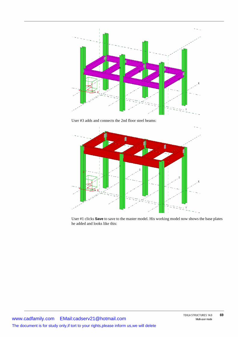
TEKLA STRUCTURES 14.0 69Multi-user mode
User #3 adds and connects the 2nd floor steel beams:
User #1 clicks Save to save to the master model. His working model now shows the base plates he added and looks like this:
www.cadfamily.com EMail:[email protected] document is for study only,if tort to your rights,please inform us,we will delete

70 TEKLA STRUCTURES 14.0Multi-user mode
User #2 clicks Save to save to the master model. His working model now shows his 1st floor framing and and User #1’s base plates:
User #3 clicks Save to save to the master model. His working model now shows all three users’s work:
www.cadfamily.com EMail:[email protected] document is for study only,if tort to your rights,please inform us,we will delete

TEKLA STRUCTURES 14.0 71Multi-user mode
To see the updated master model, Users #1 and #2 need to save to the master model again to update their working models.
Numbering setup
To lock the master model and allow the other users continue working during numbering:
1. Click Drawings & Reports > Numbering > Numbering Settings....2. In the Numbering setup dialog box, select the Synchronize with master model (save-
numbering-save) check box.
When you select this check box, you can cancel the numbering before the last save is made. This is useful, for example, if you want to check the numbering results and you find something that you still want to change.
3. Modify the other properties as required.
4. Click OK.
Tekla Structures will now save the model before and after you run full numbering, or number modified parts.
When you run numbering by clicking Drawings & Reports > Numbering > Number All Parts (Full Numbering), Tekla Structures displays a list that shows the numbering progress. When the numbering is finished, the changed numbering results are highlighted in the list.
We strongly recommend that you do not carry out numbering on more than one computer working on the multi-user model, but if you do so, number newly created parts before saving to the master model. This is because numbering modifies the part. If you save unnumbered parts and continue working with them, some other user may number the model, including your new parts, and save to the master model, and thus over-write your modifications.
www.cadfamily.com EMail:[email protected] document is for study only,if tort to your rights,please inform us,we will delete

72 TEKLA STRUCTURES 14.0Multi-user mode
When you select an item on the list, Tekla Structures highlights the corresponding object(s) in the model. If you keep the F key pressed when you select the item, Tekla Structures fits the work area of the current view around the objects.
If the numbering results are correct, click Save numbers to make the second save. To cancel the numbering before the second save, click Cancel. If you cancel the numbering, the model is returned to the state before numbering and standard files are read to all dialogs.
To review the numbering results further, click Stop timer.
To change the time frame in which Tekla Structures makes the second save, use the variable XS_NUMBERING_RESULTS_DIALOG_DISPLAY_TIME.
See also Controlling access to numbering setup (p. 78)
Numbering – specific casesIf you need to include numbering information from areas in the model that have been modeled by other users:
1. Save your working model.2. Ask all the other users to save their working models. This updates the master model.
3. Number the model. Make sure that the Synchronize with master model (save-numbering-save) checkbox is selected in the Numbering setup dialog box (see Numbering setup (p. 71)). This updates each working model, numbers the master model, and then saves the numbered master model for all users to access.
Adjusting the variable XS_SOLID_BUFFER_SIZE in Tekla Structures can improve numbering speed.
www.cadfamily.com EMail:[email protected] document is for study only,if tort to your rights,please inform us,we will delete
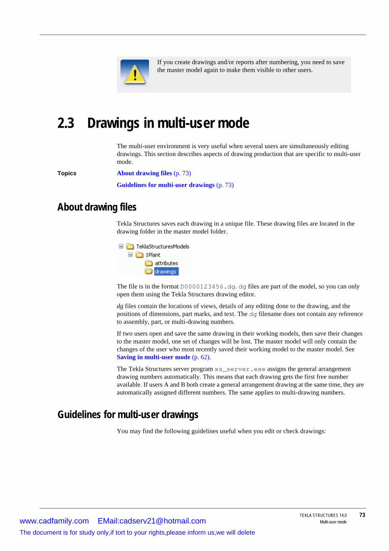
TEKLA STRUCTURES 14.0 73Multi-user mode
2.3 Drawings in multi-user modeThe multi-user environment is very useful when several users are simultaneously editing drawings. This section describes aspects of drawing production that are specific to multi-user mode.
Topics About drawing files (p. 73)
Guidelines for multi-user drawings (p. 73)
About drawing filesTekla Structures saves each drawing in a unique file. These drawing files are located in the drawing folder in the master model folder.
The file is in the format D0000123456.dg. dg files are part of the model, so you can only open them using the Tekla Structures drawing editor.
dg files contain the locations of views, details of any editing done to the drawing, and the positions of dimensions, part marks, and text. The dg filename does not contain any reference to assembly, part, or multi-drawing numbers.
If two users open and save the same drawing in their working models, then save their changes to the master model, one set of changes will be lost. The master model will only contain the changes of the user who most recently saved their working model to the master model. See Saving in multi-user mode (p. 62).
The Tekla Structures server program xs_server.exe assigns the general arrangement drawing numbers automatically. This means that each drawing gets the first free number available. If users A and B both create a general arrangement drawing at the same time, they are automatically assigned different numbers. The same applies to multi-drawing numbers.
Guidelines for multi-user drawingsYou may find the following guidelines useful when you edit or check drawings:
If you create drawings and/or reports after numbering, you need to save the master model again to make them visible to other users.
www.cadfamily.com EMail:[email protected] document is for study only,if tort to your rights,please inform us,we will delete

74 TEKLA STRUCTURES 14.0Multi-user mode
Locks for drawingsWhen you are about to open a drawing, Tekla Structures displays a notification on the status of the drawing. The options are:
• Someone is already editing it.• Someone has already edited it (drawing has been saved to their computer, but not yet to the
server).
• The drawing has already been saved and there is a newer version available on the server.
See also Clearing locks (p. 65)
2.4 Maintenance proceduresThis section contains advice on maintaining your multi-user model.
Topics Checking multi-user databases (p. 75)
Action Recommendation
Saving drawings Periodically save your working model to the master model (every 5–10 drawings).
Editing drawings • Assign each user a different range of drawings to edit.
• Lock finalized drawings.
• If Tekla Structures displays the message Data-base write conflicts detected and a drawing ID number, two or more users have opened and saved the same drawing. See About drawing files (p. 73).
Checking drawings Only check locked drawings.Printing drawings Make sure that no-one else is working with the same
drawing. If you print a drawing while someone else is editing it and then save the model, the other user’s changes will be lost, even though you have not opened, modified, or saved the drawing.
You can disable the print date by using the variable XS_DISABLE_DRAWING_PLOT_DATE.
Creating GA draw-ings
Create and assign blank GA drawings to each user. This prevents users overwriting each others changes, or creating GA drawings with the same name.
Locks for drawings are only used when a drawing is edited manually, not for example when drawings are automatically edited through cloning.
www.cadfamily.com EMail:[email protected] document is for study only,if tort to your rights,please inform us,we will delete

TEKLA STRUCTURES 14.0 75Multi-user mode
Deleting unnecessary dg files (p. 75)
Checking multi-user databasesTo preserve the integrity of your multi-user model, you need to remove any inconsistencies from the multi-user database at least once a day. This may also fix assemblies with no main part and drawings of unknown (U) type.
To remove inconsistencies from a multi-user database:
1. Have all other users exit the multi-user model.2. Click Tools > Diagnose & Repair Model > Diagnose Model.
3. Save the model.
4. Exit the model.
Deleting unnecessary dg filesEvery time you update a drawing,Tekla Structures creates a new drawing (.dg) file in the drawings sub-folder of the model. After that, the previous drawing file is not used.
You can have the unnecessary drawing files deleted automatically when the last user exits the model and saves the model. To do this, set the variable XS_DELETE_UNNECESSARY_DRAWINGS to TRUE in the global_default_env.ini file located in the ..\TeklaStructures\14.0\environments\country-independent folder.
2.5 Access rightsYou can protect user-defined attributes using privileges. You can also protect your model and drawings from accidental changes using a lock attribute. Using the lock attribute and privileges together you can even restrict some users or organizations from modifying your model.
For example, you can limit access to the model so that a checker can only change status attributes. Or you could prevent certain users from changing the user-defined attributes used for approval or manufacturing and erection status.
Topics Locking objects (p. 76)
Controlling access to attributes (p. 76)
Restricting access to model (p. 77)
We recommend that you check the multi-user databases regularly.
For additional safety, drawing files that are less than seven days old are not deleted.
www.cadfamily.com EMail:[email protected] document is for study only,if tort to your rights,please inform us,we will delete

76 TEKLA STRUCTURES 14.0Multi-user mode
Locking objectsTo protect objects from being accidentally changed, you can use a user-defined attribute called a lock attribute. You can use it for:
• parts (separately for beams, columns etc.)• bolts
• welds
• specific drawing types
• project properties
• phase properties
The lock attribute has two values, Yes and No. When set to Yes, the object is locked and you cannot modify its properties. You can only change the object’s user-defined attributes that do not affect numbering. If you try to modify a locked object, Tekla Structures shows the message "There are locked objects, see report. The operation could not be performed." and a report on access rights.
To add the lock attribute to the user interface, you need to add the following line in the object’s section in the objects.inp:
For more information on objects.inp, see Adding properties (p. 98) and Interpreting objects.inp (p. 101).
Controlling access to attributesUse the privileges.inp file to control access to user-defined attributes. It is a standard text file that you can open using any text editor.
Tekla Structures searches for the file first in the current model folder, then in the folder defined by the variable XS_INP. Below is an example file:
Each row contains three columns, separated by tabs:
objects.inpattribute("OBJECT_LOCKED", "Locked:", option,"%s", none, none, "0.0", "0.0") { value("No", 1) value("Yes", 0) }
privileges.inpattribute:APPROVED_BYCOMPANYA/fullattribute:APPROVED_BYCOMPANYB/viewattribute:APPROVED_BYeveryonenoneattribute:STATUSCOMPANYB/fullattribute:STATUSCOMPANYA/viewattribute:STATUSeveryonenone
www.cadfamily.com EMail:[email protected] document is for study only,if tort to your rights,please inform us,we will delete

TEKLA STRUCTURES 14.0 77Multi-user mode
If you do not set any privileges, all users have full rights.
Tekla Structures checks the privilege defaults in the input file privileges.inp when you create a model, and each time you open a model.
Changing rights If you need to the change the privileges, just change the privileges.inp file and re-open the model. However, you can only change the privileges of the objects the organization owns.
Restricting access to modelTo prevent a user from changing object properties, set their access to the lock attribute to none in the privileges.inp.
In this example, privileges.inp gives the users "man" and "man2" full rights to lock and unlock objects, but hides that attribute from everybody else:
See also Locking objects (p. 76)
Column Option Description
protected user-defined attribute
attribute:name Affects the user-defined attribute "name". Check the exact spelling of the name in the objects.inp.
user everyone All usersdomain/ Affects all users within the network
domain "domain". domain/nn Affects the user "nn" in the network
domain "domain".nn Affects the user "nn".
rights full User can change the user-defined attribute.
view User can view the user-defined attribute, but not change it. The field is grayed out to the user.
none The user-defined attribute is hidden from the user.
Only the person who created the model can modify its privi-leges.inp file.
privileges.inpattribute:OBJECT_LOCKEDeveryonenoneattribute:OBJECT_LOCKEDmanfullattribute:OBJECT_LOCKEDman2full
To protect other user-defined attributes, you need to list them in the privileges.inp.
www.cadfamily.com EMail:[email protected] document is for study only,if tort to your rights,please inform us,we will delete

78 TEKLA STRUCTURES 14.0Multi-user mode
Controlling access to attributes (p. 76)
Controlling access to numbering setupTo prevent unauthorized users from modifying the numbering settings, restrict their access to the numbering properties in the privileges.inp file.
To control access to the numbering properties:
Usage 1. Open the privileges.inp file in any text editor.
The file is located in the ..\environments\*your_environment*\inp folder.
2. Make the required changes in the file. You can set values to the attribute action:PartnumbersOptions.
3. Save the file.
Result If a user who has no privilege to modify properties in the Numbering Setup dialog box tries to access the dialog box, Tekla Structures displays a warning message, which states that the user does not have the required privilege.
Example In this example, only the administrator can modify the properties in the Numbering Setup dialog box:
See also Controlling access to attributes (p. 76)
Users can still run numbering even if they have no privilege to modify the numbering settings.
The option view cannot be used for controlling access to the numbering properties.
privileges.inpaction:PartnumbersOptions everyone noneaction:PartnumbersOptions ORGANIZATION\admin full
www.cadfamily.com EMail:[email protected] document is for study only,if tort to your rights,please inform us,we will delete

TEKLA STRUCTURES 14.0 79Files and Folders
3 Files and Folders
Introduction This chapter explains where Tekla Structures stores information. It describes the file types Tekla Structures contains and how to use files to customize Tekla Structures. You will also find out how to use model, project and firm folders effectively.
It also explains how the initialization files work and how you can use them to customize Tekla Structures. This chapter also includes information on the various log files and how to interpret them.
Assumed background
We assume that you have experience using Windows Explorer to manage files and folders. You should also know how to use a standard file editor, such as Wordpad.
Organization This chapter is divided into the following sections:
• Initialization files (p. 79)• File types and function (p. 85)
• Folders (p. 92)
• Customizing Tekla Structures (p. 98)
• Log files (p. 110)
3.1 Initialization filesInitialization files are used to launch Tekla Structures. They can contain many variables that you can use to configure Tekla Structures for different standards and your own style of working.
Tekla Structures automatically creates the necessary initialization files during installation.The number of initialization files it creates depends on how many country-specific environments you choose to install.
We recommend that you make all your customizations in the user.ini file, which is located in the ..\TeklaStructures\ 14.0\nt\bin folder. This way the customizations are kept when you install the next version of Tekla Structures.
Topics About variables (p. 80)
Structure (p. 81)
www.cadfamily.com EMail:[email protected] document is for study only,if tort to your rights,please inform us,we will delete

80 TEKLA STRUCTURES 14.0Files and Folders
Creating shortcuts (p. 83)
See also Appendix C, Variables (p. 285)
About variablesTekla Structures contains two kinds of variables, user variables and system variables.
User variables User variables set your personal preferences, for example the appearance of the Tekla Structures window. Tekla Structures saves user variable settings in the options_<your_username>.ini file, located in the TeklaStructures\ 14.0\nt\bin folder.
System variables options.ini contains the settings for system variables. It is located in the current model folder. To share your settings with other people, copy options.ini to the system, project or firm folders.
Setting variablesUse variables to configure Tekla Structures to suit the way you work, or to comply with specific project requirements or industry standards. You can set variables by:
Using the Advanced Options dialog box (p. 80)
OR
Editing the user.ini file (p. 80)
We recommend that you only use one of these methods to set variables. The variable settings in the Advanced options dialog box override those in the initialization files.
Using the Advanced Options dialog boxTo set a variable using the Advanced Options dialog box:
1. Click Tools > Options > Advanced Options... to open the Advanced Options dialog box.2. Browse the categories to find the variable you want to set.
3. Set the variable, then click Apply or OK in the Advanced Options dialog box.
Editing the user.ini fileTo set a variable in the user.ini file:
1. Locate the variable in the ..\TeklaStructures\ 14.0\nt\bin\user.ini file. Check that it is set and has the value you want to use.
• If it is has, you can stop here. • To change or add the variable, follow steps 2 to 5.
If required, Tekla Structures prompts you to restart Tekla Structures when you change a variable setting,
If required, Tekla Structures prompts you to restart Tekla Structures when you change a variable setting.
www.cadfamily.com EMail:[email protected] document is for study only,if tort to your rights,please inform us,we will delete

TEKLA STRUCTURES 14.0 81Files and Folders
2. Right-click the ..\TeklaStructures\ 14.0\nt\bin\user.ini file in Windows Explorer and click Open with.... Select a standard text editor from the list of available programs.
3. On a new line, type set, then the name of the variable followed by its value in a single line.
Tekla Structures only reads lines in the initialization file that start with set, for example, set XS_DIR=C:\TeklaStructures\ 14.0.
4. Save user.ini.
5. Restart Tekla Structures to activate the variable.
Different variables use different switches in Tekla Structures. To check which switch a variable uses, check Appendix C, Variables (p. 285).
Disabling variables in an initialization fileTo disable a variable, add it to the user.ini file without a value. Do not add any spaces or characters after the equals sign. See the example below:
set XS_SINGLE_CLOSE_DIMENSIONS=
StructureThis section describes the location and folder and hierarchical structure of different initialization files.
You must restart Tekla Structures after changing the initialization file for the changes to take effect.
Switch Value Example
TRUEFALSE
set XS_DISABLE_WELD_PREP_SOLID=TRUEset XS_DIMENSION_DIRECTION_REVERSED=FALSE
1 On set XS_SINGLE_CLOSE_DIMENSIONS=1
0 Off set XS_SINGLE_USE_WORKING_POINTS=0
string set XS_USER_DEFINED_BOLT_SYMBOL_TABLE=bolt_symbol_table.txt
number set XS_DEFAULT_FONT_SIZE=12
In previous versions you could disable a variable by adding "rem" before it. This does not disable the variable, if the same variable is set in the other initialization files.
rem set XS_AUTOSAVE_DIRECTORY=%XS_RUNPATH%\autosave
www.cadfamily.com EMail:[email protected] document is for study only,if tort to your rights,please inform us,we will delete

82 TEKLA STRUCTURES 14.0Files and Folders
teklastructures.ini
The file teklastructures.ini in the bin folder starts Tekla Structures.
env_global_default.ini
The file env_global_default.ini is used as a default for all environments. New options can be added in this file until they are localized and specified differently in environment-specific initialization files.
env_<your_environment>.ini
The env_<your_environment>.ini files in the environments subfolders contain all the variables that have environment-specific settings.
user.ini The user.ini file is where you save your personal settings. The variables in user.ini override those in other ini files. For example, if you have set the same variable in an .ini file in a file in environments subfolder and the user.ini file, Tekla Structures uses the value in the user.ini file.
Default settings teklastructures.ini and the .ini files in the environmentssub folders contain default settings. Tekla Structures creates them automatically during installation. We recommend that you do not modify these files.
Initialization file reading orderThe initialization files are read in the following order during startup:
teklastructures.ini in the bin folder calls the other initializa-tion files in the environments subfolders.
Add your own settings to user.ini in the bin folder.
See Variables (p. 285) for details of all variables.
www.cadfamily.com EMail:[email protected] document is for study only,if tort to your rights,please inform us,we will delete

TEKLA STRUCTURES 14.0 83Files and Folders
1. Program settings: .../nt/bin/TeklaStructures.ini2. Language-specific settings: .../nt/bin/lang_<CurrentLanguage>.ini
3. Environment and other settings: all .ini files given as program startup parameters (in the given order)
Creating customized initialization filesYou can create customer-specific initialization files that include custom settings particular to each customer, a company and/or a single project. You can also create customized initialization files for multi-user mode as needed. To do this:
1. Open the user.ini file located in the folder..\TeklaStructures\ 14.0\nt\bin using any standard text editor. Save the file with the required name, such as customer.inior project.ini.
2. Edit the file by adding the required customer settings. 3. Save the modified initialization file.
Including other initialization filesInitialization files can include or call other initialization files. You can use this functionality to create shortcuts for different purposes, for example to have different setup files depending on the client you are working for in a project such as fabricators.
Below is an example of a project initialization file that calls other initialization files.
MyProject.ini:
// The project is based on the default US imperial settingscall c:\TeklaStructures\13.1\environments\usimp\env_usimp.ini// ..but our company policy requires these changescall c:\CompanySettings\OurPolicy.ini// ..and the fabricator requires somethingcall c:\Fabricators\Fabricator1.ini// ..and then we let users to make some changes (bg color etc.)call c:\Users\user_%USERNAME%.ini
The project shortcut for MyProject:
C:\TeklaStructures\13.1\nt\bin\TeklaStructures.exe -i \\MyServer\MyProject\MyProject.ini \\MyServer\MyProject\MyModel\MyModel.db1
Creating shortcutsShortcuts are used to start teklastructures.exe with defined initializations. The Tekla Structures installation automatically creates shortcuts for the selected environments.
To create a project-specific shortcut:
1. Make a copy of the default shortcut. In the Windows Start menu, go to All Programs > Tekla Structures 14.0 > Tekla Structures 14.0 <your_environment> and right-click.
2. Select Copy from the pop-up menu.3. Paste the shortcut to your desktop.
The variable settings in the user.bat file override those in the batch files contained in the environment and language folders.
www.cadfamily.com EMail:[email protected] document is for study only,if tort to your rights,please inform us,we will delete

84 TEKLA STRUCTURES 14.0Files and Folders
4. Select the shortcut and right-click.5. Select Properties... from the pop-up menu.6. Modify the Target of the shortcut by adding the required project initializations to it.
You can use the following parameters in shortcuts:
• -i InitializationFile: Initialization file to be read during startup, for example: -i \\MyServer\MyProject\Project1.ini. You can repeat this parameter as many times as you need.
• ModelToBeOpened: Full path to the model to be opened automatically.
The maximum length of a shortcut is 256 characters. If you have prob-lems with this, you can include other necessary initialization files from your project initialization file instead of adding them to the shortcut. For more information see Including other initialization files (p. 83).
www.cadfamily.com EMail:[email protected] document is for study only,if tort to your rights,please inform us,we will delete

TEKLA STRUCTURES 14.0 85Files and Folders
3.2 File types and functionThis section describes the various types of file Tekla Structures uses and explains their uses and location.
Topics Input files (p. 85)
Data files (p. 86)
DSTV connection properties (p. 89)
Messages (p. 89)
Profiles (p. 90)
Bin (p. 91)
Fonts (p. 91)
Symbols (p. 91)
System (p. 92)
Input filesTekla Structures uses input files to control dialog boxes, as well as how components work. All input files have the extension inp.
File Description More information
objects.inp Controls the user-defined attributes
Adding properties (p. 98)
profitab.inp Contains available para-metric profiles
Customizing para-metric profiles (p. 104)
fltprops.inp Includes materials and dimensions of available flat bars
Using flat bars (p. 108)
pop_mark_parts.inp
Contains settings for pop-marking
Pop-mark settings (p. 179)
privileges.inp Controls access rights. Controlling access to attributes (p. 76)
rebar_config.inp
Contains settings for rein-forcement marks
rebar_schedule_config.inp
Contains internal bending types of reinforcing bars and their mapping to area specific bending codes..
Reinforcing bar bending types (p. 469)
component_config.inp
Contains settings for the representation and marking of cast-in fittings
analysis_design_config.inp
Contains settings for anal-ysis and design
www.cadfamily.com EMail:[email protected] document is for study only,if tort to your rights,please inform us,we will delete

86 TEKLA STRUCTURES 14.0Files and Folders
Component description filesTekla Structures uses component description files to define the properties of system components. As a general rule, you should not modify these files, as they affect the operation of system components. See When to modify.
These files are located in the folder:
..\applications\steel1\
and
..\applications\steel2\
There is one input file for each component toolbar. For example, xs_page_10.inp controls the components on toolbar 10.
When to modify You will only need to modify component description files in the following circumstances:
• If you add step profiles to the steps.dat file, you should change the xs_page_10.inp file to reflect those changes. If you do not, Tekla Structures will not display the changes in the Steps dialog box. See also Example 1: Stairs (S82).
• If you modify the Stanchion connection type used in handrailing (1024). See Example 2: Handrailing (1024) for more information.
Data filesTekla Structures reads data files from the system folder. See System folder (p. 96). These files contains data used by certain modeling tools and details. They are:
File Description
joints.dat Contains the data used in detail 1024 and modeling tool S76. Used in the Stanchion connection type field
railings.dat Contains the data for railing detail 1025. This information is used in the the railing type field.
stairs.dat Contains the data for the modeling tool S83. Used in the Stair type field
steps.dat Contains the data for modeling tool S82. Used in the Step profile field
std_flange_plates.dat
Contains the detail used in modeling tool S99. Used in the fields:
• Outer flange profile
• Inner flange profile
• Top plate profile
std_stiffener_plates.dat
Contains the data used in modeling tool S99. Used in the Horizontal stiffener profile field
marketsize.dat Contains available market sizes for certain mate-rial grade. Can be used with fMarketSize() function in the custom component editor. See also Using market sizes (p. 109).
www.cadfamily.com EMail:[email protected] document is for study only,if tort to your rights,please inform us,we will delete

TEKLA STRUCTURES 14.0 87Files and Folders
Data files and modeling toolsHere are two examples of how data files and modeling tools work together.
Example 1: Stairs (S82)
The modeling tool Stairs (S82) is on component toolbar 10, so we need to look at the file xs_page_10.inp. See Component description files (p. 86).
The entry for Stairs (S82) in the xs_page_10.inp file starts:
attribute("step_index", "j_step_profile", option,"%s", none, none,"0.0", "0.0")
Next Tekla Structures lists the options that appear in the Step profile field in the Tekla Structures Stairs (82) dialog box:
{value("DEFAULT", 1)value("PLAIN50x200", 0)value("PLAIN50x210", 0)value("PLAIN50x220", 0)value("PLAIN50x300", 0)etc...
Tekla Structures gets additional information to create the object from the file steps.dat. It reads the information in by line number, not name.
The option PLAIN50X200 in the Step profile field in the Stairs (S82) dialog box appears on line two of the xs_page_10.inp file. If you pick this option, Tekla Structures reads in the information from line 2 of the steps.dat file.
These files affect the operation of modeling tools and details.
You can open data (*.dat) files using a standard text editor. Tekla Structures lists the information in data files in text columns. You will find an explanation of the column names at the beginning of each data file.
Do not change the line order in data files or modeling tool description files.
www.cadfamily.com EMail:[email protected] document is for study only,if tort to your rights,please inform us,we will delete

88 TEKLA STRUCTURES 14.0Files and Folders
Example 2: Handrailing (1024)
Handrailing detail 1024 is on toolbar 10, so we need to look at the file xs_page_10.inp. See Component description files (p. 86).
The entry for handrailing 1024 in the file xs_page_10.inp starts:
tab_page("","jd_Parameters",3) {attribute("cut2", "j_railing_type", option, "%s", none, none, "0.0","0.0")
Line 2
You can open data (*.dat) files using a standard text editor. Tekla Structures lists the information in data files in text columns. You will find an explanation of the column names at the beginning of each data file.
www.cadfamily.com EMail:[email protected] document is for study only,if tort to your rights,please inform us,we will delete
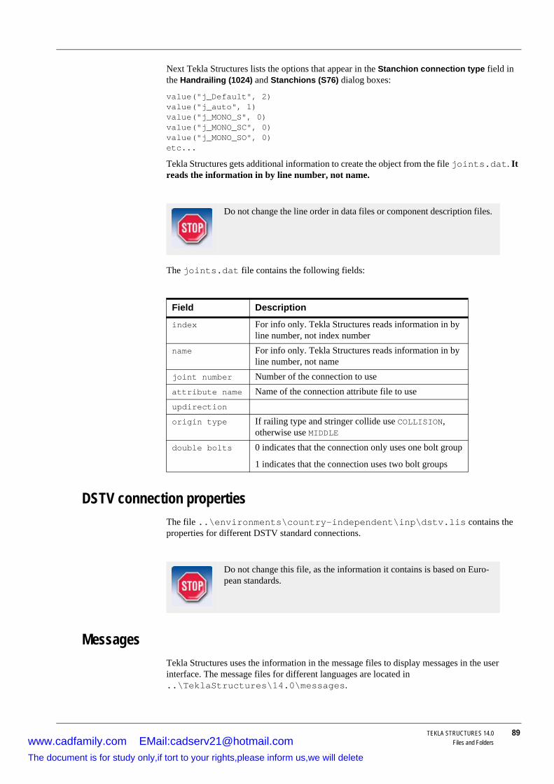
TEKLA STRUCTURES 14.0 89Files and Folders
Next Tekla Structures lists the options that appear in the Stanchion connection type field in the Handrailing (1024) and Stanchions (S76) dialog boxes:
value("j_Default", 2)value("j_auto", 1)value("j_MONO_S", 0)value("j_MONO_SC", 0)value("j_MONO_SO", 0)etc...
Tekla Structures gets additional information to create the object from the file joints.dat. It reads the information in by line number, not name.
The joints.dat file contains the following fields:
DSTV connection propertiesThe file ..\environments\country-independent\inp\dstv.lis contains the properties for different DSTV standard connections.
MessagesTekla Structures uses the information in the message files to display messages in the user interface. The message files for different languages are located in ..\TeklaStructures\14.0\messages.
Do not change the line order in data files or component description files.
Field Description
index For info only. Tekla Structures reads information in by line number, not index number
name For info only. Tekla Structures reads information in by line number, not name
joint number Number of the connection to useattribute name Name of the connection attribute file to useupdirection
origin type If railing type and stringer collide use COLLISION, otherwise use MIDDLE
double bolts 0 indicates that the connection only uses one bolt group
1 indicates that the connection uses two bolt groups
Do not change this file, as the information it contains is based on Euro-pean standards.
www.cadfamily.com EMail:[email protected] document is for study only,if tort to your rights,please inform us,we will delete

90 TEKLA STRUCTURES 14.0Files and Folders
All message files have the file extension ail.
ProfilesTekla Structures uses ASCII and binary files to manage profiles. Each environment has its own profile folder. For example, ..\environments\europe\profil\ contains the files for managing European profiles.
You can edit ASCII files using a standard text editor. Information in the binary files can only be changed via the user interface. This section describes the various file types in the ..\profil\ folder.
inp (ASCII)profitab.inp The file profitab.inp defines the names that you can use for parametric profiles. Tekla
Structures searches for this file in the standard search order (see Folder search order (p. 94)) and then the folder indicated by the variable XS_PROFDB in the initialization file. See also Customizing parametric profiles (p. 104).
rebar_database.inp
The file rebar_database.inp contains details of the reinforcement used in concrete structures. It includes both the standard bending radii and the standard hook dimensions. See also The reinforcing bar catalog (p. 142).
mesh_database.inp
The file mesh_database.inp contains details of the reinforcement meshes used in concrete structures. See also Reinforcement mesh.
cnv (ASCII)Tekla Structures uses the information in cnv files to convert materials and profiles when transferring model information using links. For example, when you use the PML or HLI links, Tekla Structures reads the cnv files from the folder indicated by the variable XS_PROFDB in the initialization file.
lis (ASCII)Tekla Structures creates lis files when you export bolt, profile and material catalogs. See also Merging profile catalogs (p. 128) and Merging bolt catalogs (p. 141).
Binary filesTekla Structures stores catalog information in the binary files, which have the file extension bin. Tekla Structures searches for these files in the following folder search order
• Model• Project
• Firm
• Folder indicated by the variable XS_PROFDB in the initialization file.
See also Customizing message files (p. 102).
www.cadfamily.com EMail:[email protected] document is for study only,if tort to your rights,please inform us,we will delete

TEKLA STRUCTURES 14.0 91Files and Folders
If you want to make catalogs available to other users, we recommend that you save catalogs in the project or firm folders. See Project and firm folders (p. 96).
These are the binary catalog files:
BinThe folder ..\nt\bin\ contains Tekla Structures executable files and the Symbol, Drawing, Report and Template Editors. It also contains some support files for Tekla Structures editors.
FontsThe variable DXK_FONTPATH in the initialization file should point to this folder. It includes the graphic fonts:
• romsim• romco
• fixfont
The Template Editor always searches the folder indicated by the variable DXK_FONTPATH, even if you configure it to also search other folders.
The variable TEMPLATE_FONT_CONVERSION_FILE points to the the conversion file Tekla Structures uses to map Tekla Structures fonts to Windows fonts. Windows fonts must have the extension ttf and be located in the ..\windows\fonts folder.
SymbolsThe folder ..\environments\country-independent\symbols\ contains the Tekla Structures symbol files. There are two types of symbol files, sym and dwg. The Symbol Editor creates sym files. dwg files contain the symbols Tekla Structures displays in rendered views (for example, connection, point and origin symbols).
The variable DXK_SYMBOLPATH in the initialization file should point to this folder.
This means that if Tekla Structures finds binary catalog files in the current model folder it does not use the catalogs located in the folder indicated by the variable XS_PROFDB in the initialization file.
File Description
assdb.db Bolt assembly catalogprofdb.bin Profile catalogmatdb.bin Material catalogscrewdb.db Bolt catalog
www.cadfamily.com EMail:[email protected] document is for study only,if tort to your rights,please inform us,we will delete

92 TEKLA STRUCTURES 14.0Files and Folders
SystemThe folder ..\environments\*your_environment*\system\ includes several file types:
rptReport templates you create with the Template Editor.
tplDrawing template files you create with the Template Editor.
layLayout definitions you create with the Drawings & Reports > Drawing Settings > Drawing Layout... option.
plotdev.binThis file contains the print device definitions you create using File > Print... > Printer Catalog.... See The printer catalog. The definitions in the system folder are accesible to all users. You can also save printer definitions in the current model folder or the project and firm folders. See Project and firm folders (p. 96).
Tekla Structures searches for plotdev.bin in the model, project and firm folders, then the folder indicated by the variable XS_DRIVER.
Wizard files (dproc)Tekla Structures wizard files automate drawing creation by performing a series of actions you would otherwise have to perform manually. Wizard files have the file extension dproc. Tekla Structures searches the system folder (see System folder (p. 96)) for wizard files. See also Creating AutoDrawings wizard files (p. 106).
3.3 FoldersThis section describes how Tekla Structures stores the files associated with a model and explains how to use folders to manage files, including those you customize to project and company specifications.
Topics Folder structure (p. 93)
Folder search order (p. 94)
Model folder (p. 95)
System folder (p. 96)
Project and firm folders (p. 96)
The Template Editor always searches for symbols in the folder indicated by the variable DXK_SYMBOLPATH.
www.cadfamily.com EMail:[email protected] document is for study only,if tort to your rights,please inform us,we will delete

TEKLA STRUCTURES 14.0 93Files and Folders
Template folder (p. 97)
Folder structureThis is a quick reference to the default locations for folders and files discussed in this section. You will find more detailed information on files and folders throughout this chapter.
Catalog files
System folder
Firm folder
Message files
Bin folder
Project folder
Model folder
www.cadfamily.com EMail:[email protected] document is for study only,if tort to your rights,please inform us,we will delete

94 TEKLA STRUCTURES 14.0Files and Folders
Folder search orderWhen you open a model, Tekla Structures searches for the associated files in specific folders in a set order.
It is important that you locate files in the correct folders. Once Tekla Structures finds the associated files, it stops searching. So files that have the same name but are located lower down the search order are ignored.
The folder search order is:
Tekla Structures does not search for certain files in exactly this order. The exceptions are listed below. The table also includes links to more information.
The exceptions are:
Folder Defined by
Current model The open modelProject variable XS_PROJECTFirm variable XS_FIRMSystem variable XS_SYSTEM
File (type) More information
objects.inp Adding properties (p. 98)*.dat files Data files (p. 86)Templates Search order:
• XS_TEMPLATE_DIRECTORY
• Model folder
• XS_PROJECT
• XS_FIRM
• XS_TEMPLATE_DIRECTORY_SYSTEM
• XS_SYSTEM
For more information, see Template folder (p. 97)
Catalogs Profile, bolt, material and reinforcement cata-logs.
Search order:
• Model folder• XS_PROJECT
• XS_FIRM
• Folder indicated by the variable XS_PROFDB
For more information, see Binary files (p. 90).
www.cadfamily.com EMail:[email protected] document is for study only,if tort to your rights,please inform us,we will delete

TEKLA STRUCTURES 14.0 95Files and Folders
Model folderTekla Structures stores all files associated with a model in a folder it creates with the same name as the model database file (*.db1). In multi-user mode all users access the same model folder. To view the files in the model folder, click File > Open model folder.
Saved attributesWhen you change object properties, templates, reports, connections, etc. and then click Save or Save as in the dialog box, Tekla Structures saves the changed files in the current model folder in the attributes sub-folder. See also Project and firm folders (p. 96) and Folder search order (p. 94).
Tekla Structures creates the following files in the model folder:
Do not use the system folder to store customizes files. You will avoid having problems or doing a lot of unecessary work when you upgrade. See System folder (p. 96) and Project and firm folders (p. 96).
File/extension Description
db1 The model database. Tekla Structures uses the filename without the extension to name the model folder.
db2 Numbering database. The filename without the extension should be the same as the model folder.
xslib.db1 Contains user-defined connections and details. Can be copied from one model folder to another.
xslib.db2 Stores numbering information.xs_user.user_name Contains interface settings for each user, such
as drag and drop settings. See Mouse and pointer settings.
xsdb.xs When you open a project database, Tekla Structures displays the name in the Open dialog box, if it finds this file in the current model folder.
bak Tekla Structures saves a backup copy of the model databases each time you save the model. To restore a previous version of the model, rename the *.bak file to *.db1.
www.cadfamily.com EMail:[email protected] document is for study only,if tort to your rights,please inform us,we will delete

96 TEKLA STRUCTURES 14.0Files and Folders
System folderThe system folder contains templates for drawings and reports and object settings and properties. Files in the system folder are read-only. See Project and firm folders (p. 96) and Folder search order (p. 94).
The location of the system folder is defined by the variable XS_SYSTEM in the initialization file.
Project and firm foldersYou can create project and firm folders for customized files. This is a useful technique if you want to store the files for future use, or want to retain them when you install a new release.
Property files are always saved in the attributes folder under the current model folder, for example, ..\TeklaStructuresModels\my_building\attributes.
You can copy these files to the project or firm folders. See Folder search order (p. 94) for important information on where to locate files.
dg Located in the sub-folder ..\drawings under the model folder. These are drawing files, which include information on how each drawing was created. Tekla Structures also stores information on current drawings in the model database. Opening or printing a drawing opens the corresponding *.dg file.
Do not manually delete *.dg files. Tekla Structures deletes *.dg files when you delete a drawing.
xsr Tekla Structures reportsnc1 Neutral files in DSTV format for NC tooling
machines. The filename consists of the part mark and this extension.
You can change the file extension in the NC files dialog box Tekla Structures displays when you click File > Export > CNC > Create NC Files.... By default it is nc1.
Log files See Log files (p. 110).This_is_multiuser_model
Contains information about the PC running xs_server.exe.
Do not alter or delete this file in normal circumstances. If, you move a model to a different server, you should delete this file. Tekla Structures generates a new file with the same name.
File/extension Description
Do not store customized files in the system folder. Tekla Structures may replace these files when you install a new release. This is not the case with files in the project and firm folders. See Project and firm folders (p. 96).
www.cadfamily.com EMail:[email protected] document is for study only,if tort to your rights,please inform us,we will delete

TEKLA STRUCTURES 14.0 97Files and Folders
Tekla Structures does not replace files in the project and firm folders when you install a new release, so you retain your customized files without having to cut and paste, or export and import from previous versions.
Create firm and project folders for example on the same level as the Tekla Structures folder and make them available in all versions using variables: XS_PROJECT and XS_FIRM.
Project folderThe project folder is where you should store files you customize for a particular project.The location of the project folder is defined by the variable XS_PROJECT in the initialization file. See also Folder search order (p. 94).
You need to create a project folder manually, then edit the variable XS_PROJECT to point to that folder.
Firm folderUse the firm folder to store files customized for a particular organization or company. The location of the firm folder is defined by the variable XS_FIRM in the initialization file. See also Folder search order (p. 94).
You need to create a firm folder manually, then edit the variable XS_FIRM to point to it.
Example You regularly work for a company that has specific drawing layout standards it expects you to use. Customize the drawing templates once for the company and save them in a sub-folder located under the firm folder. You can then use the customized drawing templates for all future projects for that company. And all users can access the customized files.
Template folderTekla Structures searches for the Template Editor v. 3.3 templates and reports in the following order:
To modify the variables, click Tools > Options > Advanced Options... > File Locations.
Tekla Structures searches for version 2.2 templates in two locations, in XS_TEMPLATE_DIRECTORY and in the first folder containing templates:
• model• project
• firm
• system templates
• system
Folder Defined by variable
Folder containing your templates
XS_TEMPLATE_DIRECTORY
ModelProject XS_PROJECT
Firm XS_FIRM
Environment-specific system templates
XS_TEMPLATE_DIRECTORY_SYSTEM
System XS_SYSTEM
www.cadfamily.com EMail:[email protected] document is for study only,if tort to your rights,please inform us,we will delete

98 TEKLA STRUCTURES 14.0Files and Folders
When Tekla Structures finds a template in one of these folders, it stops searching.
3.4 Customizing Tekla StructuresThis section explains how to customize Tekla Structures. It covers the following subjects:
Adding properties (p. 98)
Interpreting objects.inp (p. 101)
Customizing message files (p. 102)
Changing the language of the user interface (p. 103)
Customizing parametric profiles (p. 104)
Save defaults (p. 105)
Creating AutoDrawings wizard files (p. 106)
Unfolding parameters (p. 107)
Using flat bars (p. 108)
Using market sizes (p. 109)
Adding propertiesMany dialog boxes contain user-defined attributes for various objects, including beams, columns, bolts and drawings, in Tekla Structures. You can use the ..\environments\country_independent\inp\objects.inp file to define your own attributes for these objects.
Tekla Structures displays these fields when you click User defined attributes or the User attributes tab in the relevant dialog box. You can then use these values in reports and drawings.
When you upgrade Tekla Structures, the user-defined attributes that you have added in the objects.inp file in the previous version of Tekla Structures are automatically copied to version 14.0 or later.
The objects.inp file reads attributes in order from the folders listed in the table below starting with the model folder:
See Project and firm folders (p. 96).
Folder Defined by variable
ModelProject XS_PROJECT
Firm XS_FIRM
System XS_SYSTEM
inp XS_INP
www.cadfamily.com EMail:[email protected] document is for study only,if tort to your rights,please inform us,we will delete

TEKLA STRUCTURES 14.0 99Files and Folders
The files are merged so that if there are user-defined attributes in any of the files, they are displayed in the user interface. Tekla Structures merges the files in a way that eliminates duplicate attributes.
If Tekla Structures encounters the same attribute name in different objects.inp files, the attribute from the first read objects.inp file will be used.
Changing user-defined fieldsYou can customize existing User fields shown in dialog boxes. You can also add more user-defined fields. See also User-defined fields in templates (p. 100).
Example You want to change the name of the user-defined attribute User Field 1 in the Column dialog box, which by default looks like this:
Steps 1. Open the objects.inp file using a standard text editor.2. Find the section:
/******************************************************//* Part attributes *//******************************************************/
3. Each attribute is listed on a new line and starts with the word attribute. Find the line:
attribute("USER_FIELD_1", "j_user_field_1", string, "%s", no, none, "0.0", "0.0")
4. Change the line to read:
attribute("MY_INFO_1", "My Info 1", string, "%s", no, none, "0.0", "0.0")
You should only edit the user-defined fields in the objects.inp file. Do not change other standard field names or values.
www.cadfamily.com EMail:[email protected] document is for study only,if tort to your rights,please inform us,we will delete

100 TEKLA STRUCTURES 14.0Files and Folders
5. Save the objects.inp file.
6. Close Tekla Structures and restart the program for the changes to take effect. The Column properties dialog box will now look like this:
User-defined fields in templatesThis section explains how to use user-defined attributes with Template Editor version 2.2.
For more information on how to use user-defined attributes in Template Editor version 3.3, see User-defined attributes in templates (p. 426).
If you change the name of a user-defined field, or create a new user-defined field, you need to modify the legend_text.fields located in the ..nt\bin\ folder, before you can select the field from a list in the Template Editor. You can also use user-defined fields without modifying the legend_text.fields, if you just type the field name correctly. For the example shown in Changing user-defined fields (p. 99), change legend_text.fields as follows:
Example TITLE3 CHARACTER LEFT 40MY_INFO_1 CHARACTER LEFT 40USER_FIELD_2 CHARACTER LEFT 40USER_FIELD_3 CHARACTER LEFT 40USER_FIELD_4 CHARACTER LEFT 40
Attribute names must be unique. The maximum number of characters in a name is 19.
This change affects dialog boxes of all parts, not only columns.
www.cadfamily.com EMail:[email protected] document is for study only,if tort to your rights,please inform us,we will delete

TEKLA STRUCTURES 14.0 101Files and Folders
Effect on numberingYou can set whether the user-defined attribute affects numbering or not. See Numbering settings. This is useful when you have members that are identical in all respects, apart from their user-defined attributes.
Consider attribute
If you want Tekla Structures to consider the user-defined attribute when numbering, use the option yes in objects.inp, see Interpreting objects.inp (p. 101). In this case, Tekla Structures assigns different marks to parts that are identical, but have different user-defined attributes.
You must also change the entry for the field in the Part attributes section of the objects.inp file for the user-defined value to be considered when numbering.
Ignore attribute If you want Tekla Structures to ignore the user-defined attribute when numbering, use the option no in objects.inp. In this case, Tekla Structures assigns the same mark to parts that are identical, but have different user-defined attributes.
Interpreting objects.inpThe main components of objects.inp are shown below. See also Fields in objects.inp (p. 102).
Make sure Tekla Structures does not already use the attribute name you use. Consider using a prefix that ensures the name is unique, for example, your initials, or an abbreviation of your company name.
Do not use spaces or reserved characters in attribute names.
Only user-defined attributes of parts affect numbering. User-defined attributes of other objects, such as phases, projects, drawings, etc. do not affect numbering.
attribute or unique_attibute
Attribute name
Prompt
Affects numbering
Default value
Type of values
www.cadfamily.com EMail:[email protected] document is for study only,if tort to your rights,please inform us,we will delete

102 TEKLA STRUCTURES 14.0Files and Folders
The text you enter in the prompt section of the attribute is exactly what Tekla Structures displays in dialog boxes. Some default attributes have prompts like j_comment, meaning that the prompt comes from the joints.ail message file. For more information, read Messages (p. 89).
To include an attribute in a report or template, add the name of the attribute to your layout in the Template Editor. When you run a report or create a drawing, Tekla Structures displays the current value of the attribute.
Fields in objects.inpThe objects.inp file contains the following field names:
Customizing message filesYou can customize message files in Tekla Structures.
Example The message file by_number.ail contains both prompts and default text (or text strings) that Tekla Structures uses in drawings. If you want to change the text Tekla Structures uses for near side plates from N/S to NS, do the following:
Field Description
attribute Regular attribute, which is copied with other part properties.
unique_attribute Non-copyable attribute. The value of the attribute is never copied to another part. For example part checking status attributes are usually non-copyable.
attribute_name Attribute name, used to find the attribute valuelabel_text Text Tekla Structures displays in the dialog boxvalue_type integer, float for numbers
string for text
option for lists
date for date with small calendar
date_time_min for date and time [12:00] with small calendar
date_time_sec for date and time [12:00:00] with small calendar
field_format Definition of the field format in the dialog box. Uses C program terminology:
• "%s" for strings• "%d" for numbers
consider_in_numbering
See Effect on numbering (p. 101)
check_switch none, check_max, check_min, check_maxmin
attribute_value_max
The maximum possible value for the attribute
attribute_value_min
The maximum possible value for the attribute
www.cadfamily.com EMail:[email protected] document is for study only,if tort to your rights,please inform us,we will delete
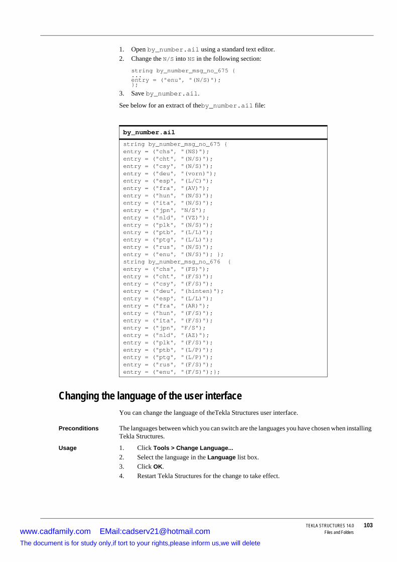
TEKLA STRUCTURES 14.0 103Files and Folders
1. Open by_number.ail using a standard text editor.2. Change the N/S into NS in the following section:
string by_number_msg_no_675 {...entry = ("enu", "(N/S)");};
3. Save by_number.ail.
See below for an extract of theby_number.ail file:
Changing the language of the user interfaceYou can change the language of theTekla Structures user interface.
Preconditions The languages between which you can switch are the languages you have chosen when installing Tekla Structures.
Usage 1. Click Tools > Change Language...2. Select the language in the Language list box.3. Click OK.4. Restart Tekla Structures for the change to take effect.
by_number.ail
string by_number_msg_no_675 { entry = ("chs", "(NS)"); entry = ("cht", "(N/S)"); entry = ("csy", "(N/S)"); entry = ("deu", "(vorn)"); entry = ("esp", "(L/C)"); entry = ("fra", "(AV)"); entry = ("hun", "(N/S)"); entry = ("ita", "(N/S)"); entry = ("jpn", "N/S"); entry = ("nld", "(VZ)"); entry = ("plk", "(N/S)"); entry = ("ptb", "(L/L)"); entry = ("ptg", "(L/L)"); entry = ("rus", "(N/S)"); entry = ("enu", "(N/S)"); };string by_number_msg_no_676 { entry = ("chs", "(FS)"); entry = ("cht", "(F/S)"); entry = ("csy", "(F/S)"); entry = ("deu", "(hinten)"); entry = ("esp", "(L/L)"); entry = ("fra", "(AR)"); entry = ("hun", "(F/S)"); entry = ("ita", "(F/S)"); entry = ("jpn", "F/S"); entry = ("nld", "(AZ)"); entry = ("plk", "(F/S)"); entry = ("ptb", "(L/P)"); entry = ("ptg", "(L/P)"); entry = ("rus", "(F/S)"); entry = ("enu", "(F/S)");};
www.cadfamily.com EMail:[email protected] document is for study only,if tort to your rights,please inform us,we will delete

104 TEKLA STRUCTURES 14.0Files and Folders
See also Languages and environments
Customizing parametric profilesThe file profitab.inp defines the names that you can use for parametric profiles in Tekla Structures. You can customize this file to add more parametric profile names.
See also The profile catalog (p. 117).
Example You want to use parametric plate profiles with a different name, PLTE.
1. Open the profitab.inp file in a standard text editor.2. Add the line:
PLTE ! PL ! +2 ! ! 1 ! 2 ! ! !
3. Save profitab.inp to the current model folder and close the file.
See also Project and firm folders (p. 96).
Interpreting profitab.inpThe first block in this file is the column titles. It also contains an explanation of possible values.
The language you in which you install Tekla Structures will be the default language of the user interface.
Title Description
Prefix Prefix Tekla Structures uses for the parametric profile. See also Appendix A, Parametric Profiles.
Type The parametric profile type, e.g. I profile.SO Sort order.
The available options are:
• -1: Decreasing sorting order• +1: Increasing sorting order
• 0: No sorting order
• 2: Name increasing, value decreasing
• -2: Name decreasing, value increasing
For example, if your input is PLT200*10 or PLT10*200 and you select 2, the result in the output (such as a report) for both cases is PLT200*10. If you select -2, the result for both cases is PLT10*200.
Z Unit of measure used when inputting data
www.cadfamily.com EMail:[email protected] document is for study only,if tort to your rights,please inform us,we will delete

TEKLA STRUCTURES 14.0 105Files and Folders
Save defaultsYou may find it useful to create a set of standard files for a new project, or to set up Tekla Structures to suit the way you work. You can copy these standard files to the project or firm folders for future use. See Project and firm folders (p. 96).
Many dialog boxes Tekla Structures displays when you are modeling contain properties for objects (beams, columns, modeling tools, etc.). Typically they have a Standard option in the Load list box. By default Tekla Structures uses the settings in the Standard file when applying commands.
Use Tools > Defaults > Save Defaults to save a set of Standard files in the current model folder. Tekla Structures creates the following files:
MI Minimum number of parameters you can use in the Select profile dialog box.
For example, a rectangular hollow section has sub-types: h*t, h*b*t, h1*b1-h2*b2*t.
You define SHS with a minimum of two and a maximum of two parameters. When you use the Prefix option in the Select profile dialog box, you will only have the option h*t. Using the same example, SHS300*200*5 will not be available either.
MA Maximum number of parameters you can use in the Select profile dialog box. See MI above for example.
G3-NAME Only used for user-defined parametric profiles. Used by Tekla Structures to find the generation component.
Z3-NAME Only used for user-defined parametric profiles.
Identifies the modeling tool name.
Title Description
File Dialog box
standard.asv Autosave propertiesstandard.clm Column propertiesstandard.cpl Contour plate propertiesstandard.crs Beam/orthogonal beam propertiesstandard.dia Twin profile propertiesstandard.fms Plotting framesstandard.fpl Folded platestandard.ler Layer propertiesstandard.mvi Model view propertiesstandard.num Setup - Numberingstandard.prf Project properties
Numbering and coefficient information from the Options dialog box.
www.cadfamily.com EMail:[email protected] document is for study only,if tort to your rights,please inform us,we will delete

106 TEKLA STRUCTURES 14.0Files and Folders
Creating standard filesYou can also create standard files not listed above. Simply change the properties of a file, then save it as standard (use lower case). Tekla Structures saves standard files to the current model folder. See System folder (p. 96) for more on using standard files. See also Project and firm folders (p. 96).
Customizing other filesTekla Structures also stores a number of files, all of which contain object properties, in the current model folder. Tekla Structures creates these files when you click Save or Save as in dialog boxes.
Example You change the standard column properties to create a new type of column you call custom1. When you click Save as, Tekla Structures creates the file custom1.clm in the current model folder.
Creating AutoDrawings wizard filesYou can create your own AutoDrawings wizard files using any standard text editor. Use the existing wizard files as examples to construct your own.
A typical AutoDrawings wizard file includes several sets of drawing requests containing drawing, attribute and part settings to apply to selected objects, as well as a selection filter. The order of sets is important, as Tekla Structures only creates one drawing for each object.
Example The AutoDrawings wizard file creates an assembly drawing for an object that fulfills the selection filter criteria in one set. Tekla Structures will not create another assembly drawing for that object, even if it matches the criteria of the selection filter in later sets in the same wizard file.
Interpreting a wizard file
Wizard files consist of the following entries. Note the use of parentheses.
set_drawing_type(assembly)
This line defines the type of drawing the wizard creates. The drawing type appears in parentheses. The options are:
standard.prt Beam propertiesstandard.scr Bolt propertiesstandard.stp Setup - Preferencesstandard.wld Weld properties
File Dialog box
See Appendix D, File extensions (p. 415), for a full list of files Tekla Structures creates in this way.
Option Creates
single workshop drawingsassembly assembly drawingsmulti_single workshop multi-drawings
www.cadfamily.com EMail:[email protected] document is for study only,if tort to your rights,please inform us,we will delete
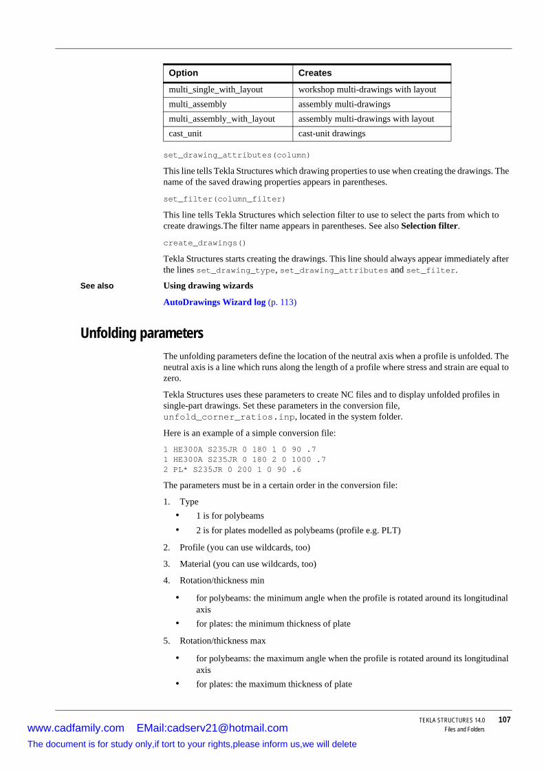
TEKLA STRUCTURES 14.0 107Files and Folders
set_drawing_attributes(column)
This line tells Tekla Structures which drawing properties to use when creating the drawings. The name of the saved drawing properties appears in parentheses.
set_filter(column_filter)
This line tells Tekla Structures which selection filter to use to select the parts from which to create drawings.The filter name appears in parentheses. See also Selection filter.
create_drawings()
Tekla Structures starts creating the drawings. This line should always appear immediately after the lines set_drawing_type, set_drawing_attributes and set_filter.
See also Using drawing wizards
AutoDrawings Wizard log (p. 113)
Unfolding parametersThe unfolding parameters define the location of the neutral axis when a profile is unfolded. The neutral axis is a line which runs along the length of a profile where stress and strain are equal to zero.
Tekla Structures uses these parameters to create NC files and to display unfolded profiles in single-part drawings. Set these parameters in the conversion file, unfold_corner_ratios.inp, located in the system folder.
Here is an example of a simple conversion file:
1 HE300A S235JR 0 180 1 0 90 .71 HE300A S235JR 0 180 2 0 1000 .72 PL* S235JR 0 200 1 0 90 .6
The parameters must be in a certain order in the conversion file:
1. Type• 1 is for polybeams• 2 is for plates modelled as polybeams (profile e.g. PLT)
2. Profile (you can use wildcards, too)
3. Material (you can use wildcards, too)
4. Rotation/thickness min
• for polybeams: the minimum angle when the profile is rotated around its longitudinal axis
• for plates: the minimum thickness of plate
5. Rotation/thickness max
• for polybeams: the maximum angle when the profile is rotated around its longitudinal axis
• for plates: the maximum thickness of plate
multi_single_with_layout workshop multi-drawings with layoutmulti_assembly assembly multi-drawingsmulti_assembly_with_layout assembly multi-drawings with layoutcast_unit cast-unit drawings
Option Creates
www.cadfamily.com EMail:[email protected] document is for study only,if tort to your rights,please inform us,we will delete
108 TEKLA STRUCTURES 14.0Files and Folders
6. Flag
• 1 is for sharp folds• 2 is for curved bends
7. Angle/radius min
• the minimum angle of sharp folds• the minimum radius of curved bends
8. Angle/radius max
• the maximum angle of sharp folds• the maximum radius of curved bends
9. Ratio
• defines how much the profile stretches or shrinks when unfolded. Ratio = (1 - the relative location of the neutral axis). If only the inner surface of the profile shrinks, the ratio is 1. If only the outer surface of the profile stretches, the ratio is 0. By default, the ratio is 0.5 for length calculation and 0.0 for bending radius calculation.
Tekla Structures applies the unfolding ratio if the profile properties are within the range indicated by the minimum and maximum values.
Using flat barsWhen you have completed the model, you can have Tekla Structures show plates as the equivalent flat bars for manufacturing. Tekla Structures displays the plates as flat bars in reports and drawings.
To show plates as flat bars:
1. Set the variable XS_USE_FLAT_DESIGNATION=TRUE.2. Indicate the prefix you want to use for flat bars using the variable XS_FLAT_PREFIX. For
example, set XS_FLAT_PREFIX=FLAT.
3. Define materials, thickness, and width of available flat bars in the fltprops.inp file. See Defining flat bar sizes with fltprops.inp (p. 109).
4. By default, Tekla Structures only compares plate width with the available flat bar dimensions.
• To include plate length, set the variable XS_CHECK_FLAT_LENGTH_ALSO=TRUE.• To define the tolerance between the actual and standard gusset width, set the variable
XS_STANDARD_GUSSET_WIDTH_TOLERANCE.
To define the rotation angle, set the work plane by the first three points of the polybeam. Set the rotation angle in the Rotation field in the Beam properties dialog box.
To prevent Tekla Structures displaying the profile in metric units in the US Imperial version, add the flat bar prefix to the profitab.inp file as a parametric profile.
www.cadfamily.com EMail:[email protected] document is for study only,if tort to your rights,please inform us,we will delete
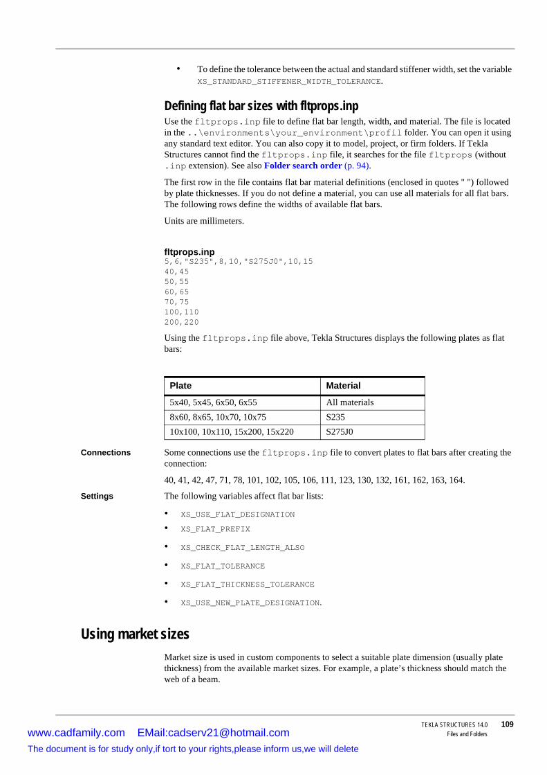
TEKLA STRUCTURES 14.0 109Files and Folders
• To define the tolerance between the actual and standard stiffener width, set the variable XS_STANDARD_STIFFENER_WIDTH_TOLERANCE.
Defining flat bar sizes with fltprops.inpUse the fltprops.inp file to define flat bar length, width, and material. The file is located in the ..\environments\your_environment\profil folder. You can open it using any standard text editor. You can also copy it to model, project, or firm folders. If Tekla Structures cannot find the fltprops.inp file, it searches for the file fltprops (without .inp extension). See also Folder search order (p. 94).
The first row in the file contains flat bar material definitions (enclosed in quotes " ") followed by plate thicknesses. If you do not define a material, you can use all materials for all flat bars. The following rows define the widths of available flat bars.
Units are millimeters.
Using the fltprops.inp file above, Tekla Structures displays the following plates as flat bars:
Connections Some connections use the fltprops.inp file to convert plates to flat bars after creating the connection:
40, 41, 42, 47, 71, 78, 101, 102, 105, 106, 111, 123, 130, 132, 161, 162, 163, 164.
Settings The following variables affect flat bar lists:
• XS_USE_FLAT_DESIGNATION
• XS_FLAT_PREFIX
• XS_CHECK_FLAT_LENGTH_ALSO
• XS_FLAT_TOLERANCE
• XS_FLAT_THICKNESS_TOLERANCE
• XS_USE_NEW_PLATE_DESIGNATION.
Using market sizesMarket size is used in custom components to select a suitable plate dimension (usually plate thickness) from the available market sizes. For example, a plate’s thickness should match the web of a beam.
fltprops.inp5,6,"S235",8,10,"S275J0",10,1540,4550,5560,6570,75100,110200,220
Plate Material
5x40, 5x45, 6x50, 6x55 All materials8x60, 8x65, 10x70, 10x75 S23510x100, 10x110, 15x200, 15x220 S275J0
www.cadfamily.com EMail:[email protected] document is for study only,if tort to your rights,please inform us,we will delete
110 TEKLA STRUCTURES 14.0Files and Folders
To use market sizes, you must define a custom component using a custom component editor.
1. In the Variables dialog box, add the function =fMarketSize(material, thickness, extrastep) for a parameter.
2. Define the available material sizes in the marketsize.dat file. See Defining market sizes with marketsize.dat (p. 110) for instructions.
Defining market sizes with marketsize.datUse the marketsize.dat file to define available thicknesses (or any other dimension) for each material grade. The file is located in the ..\environments\your_environment\profil folder. You can open it using any standard text editor.
A material grade element must begin each row followed by a comma-separated list of available plate thicknesses. These units are described in millimeters.
ExampleIf the following row is in the marketsizes.dat file:
S235JR,6,9,12,16,19,22
then the available market size plate thicknesses for S235JR plates are 6, 9, 12, 16 and 22 mm. So the function =fMarketSize("S235JR",10,0) would return 12, and =fMarketSize("S235JR",10,1) would return 16 (one size up).
You can also use the function without entering any size up:
=fMarketSize("SS400",7) which is the equivalent of =fMarketSize("SS400",7,0)
3.5 Log filesTekla Structures writes information to log files when you perform operations such as numbering or saving a model. This section describes these log files and how to interpret them.
Topics Tekla Structures log files (p. 110)
Viewing log files (p. 114)
Direct access to parts from log files (p. 114)
Tekla Structures log filesThis section contains information on the following log files in Tekla Structures.
marketsize.datS235JR,6,9,12,16,19,22SS400,1.6,2.3,3.2,4.5,6,9,12,16,19,22,25,28,32,38DEFAULT,6,9,12,16,19,22,25,28,32,38
All log files are located in the current model folder.
www.cadfamily.com EMail:[email protected] document is for study only,if tort to your rights,please inform us,we will delete

TEKLA STRUCTURES 14.0 111Files and Folders
Numbering history logTekla Structures stores a full numbering history in the file numbering.history. The file has full details of each time numbering was carried out on the model. Tekla Structures places each session in a different block.
File Description
check_database.log
Tekla Structures writes information to this log file when you use the Correct database command. If inconsistencies are found in a part, the part id is written in this log. You can then access the part using the technique described in Direct access to parts from log files (p. 114).
conflict.log This file lists write conflicts. You can view this file automatically. A write conflict occurs in multi-user mode when more than one user changes an object.
drawing_cloning.log
History of cloning drawings.
drawing_history.log
History of drawing creation. See Drawing history log (p. 113) for more information.
dstv_nc.log Tekla Structures writes information to this file about the assemblies processed each time you create NC files. If you use the NC file classifier, this log file contains additional information on the process, e.g. which machine you used, etc.
Also contains error messages.filetran-error.log
Only used for cold rolled components, e.g. Albion, Ayrshire, Hispan etc. Tekla Structures writes error messages to this file if transfer macros fail.
numbering.history
This file has full details of each time numbering was carried out on the model. See Numbering history log (p. 111) for more information.
save_history.log Tekla Structures writes information to this file each time you save a model.
wizard.log Tekla Structures writes a log file when you run a wizard. See AutoDrawings Wizard log (p. 113) for more information.
TeklaStruc-tures.log
Contains information on the entire Tekla Struc-tures session (from opening the model to closing it), e.g. errors, which catalogs you are using, etc.
analysis.log Tekla Structures writes information to this file when you run the analysis. Analysis log file contains also information on errors that occur during load distribution.
www.cadfamily.com EMail:[email protected] document is for study only,if tort to your rights,please inform us,we will delete
112 TEKLA STRUCTURES 14.0Files and Folders
Interpreting numbering.historyThe header line of each block contains details of the user who carried out the numbering and the date.
*** Numbering (kke): Tue Jun 27 10:38:03 2000
The next lines contain details of the numbering settings used:
Full numbering Compare modified to old parts Compare new to old parts Tolerance: 1.000000
Then a list of defined series, prior to numbering. In this example, the first line means that in the series PL/1 the highest part position number is 1 and the highest assembly postion number is 0.
PL/1 Max Part 1 Max Assembly 0 B/1 Max Part 1 Max Assembly 0 A/1 Max Part 0 Max Assembly 14 P/1 Max Part 12 Max Assembly 0 /1001 Max Part 2 Max Assembly 0
Tekla Structures then lists information on the parts and assemblies numbered.
Column headings appear in this example, they do not appear in the file itself.
Part/ Numbering Position numberassembly ID series Old NewPart 124228 series:P/1 P/9 -> P/13Part 1541381 series:/2001 /0 -> /2001Part 1541698 series:/2001 /0 -> /2002Part 1541760 series:/1001 /0 -> /1005Part 1541820 series:/1001 /0 -> /1006Part 1541879 series:/1001 /0 -> /1004Part 1541941 series:/1001 /0 -> /1006Part 1542095 series:/1001 /0 -> /1007Part 1542129 series:/1001 /0 -> /1003Part 1542142 series:/1001 /0 -> /1003Part 1542153 series:/1001 /0 -> /1003Part 1542164 series:/1001 /0 -> /1003Part 1542175 series:/1001 /0 -> /1003Part 1542186 series:/1001 /0 -> /1003
Tekla Structures then shows an updated list of the defined series.
/2001 Max Part 2 Max Assembly 0 PL/1 Max Part 1 Max Assembly 0 B/1 Max Part 1 Max Assembly 0 A/1 Max Part 0 Max Assembly 14 P/1 Max Part 13 Max Assembly 0 /1001 Max Part 7 Max Assembly 0 Assembly 124236 series:A/1 A/11 -> A/15
The final line of the block shows the end of the numbering session.
*** Operation finished Tue Jun 27 10:38:03 2000 Full numbering
If both the part and assembly numbers here are not zero and you have set the variable XS_USE_ASSEMBLY_NUMBER_FOR to MAIN_PART, there may have been a conflict during numbering.
www.cadfamily.com EMail:[email protected] document is for study only,if tort to your rights,please inform us,we will delete

TEKLA STRUCTURES 14.0 113Files and Folders
If you remove or delete the file numbering.history, Tekla Structures generates a new file with the same name when you next run numbering. The new file does not contain a history of previous numbering sessions.
Overlapping part/assembly seriesTekla Structures records the error message shown in the following example in the numbering.log when you do not have enough free numbers in the numbering series.
Example Assembly numbering series overlap: Position number 1 in series 0 overlaps with position number 1 in series 1.
See also Numbering.
Drawing history logUse the variable XS_DRAWING_HISTORY_LOG_TYPE in the Drawing properties category in the Advanced options dialog box, to define what information Tekla Structures writes in the numbering history log file.
You can use all, or any combination of, these options:
• NEW
• DELETED
• MODIFIED
Separate the options using the _ character, for example, XS_DRAWING_HISTORY_LOG_TYPE=NEW_DELETED.
AutoDrawings Wizard logTekla Structures writes a log file when you run an AutoDrawings wizard. The log file contains information about errors, number of drawings created, commands used etc.
You can configure whether or not Tekla Structures creates a log file and how it is displayed using the Advanced tab in the AutoDrawings dialog box.
Create log options:
• NoTekla Structures does not create a log file.
• Create
Tekla Structures creates a new log file and deletes the old one.
• Append
Tekla Structures adds a new entry to the existing log file.
Display log options:
• NoTekla Structures does not display the log,
• With associated viewer
Tekla Structures displays the log file in an associated viewer (e.g. Notepad) when you run the wizard. You can edit the log file.
• On dialog
www.cadfamily.com EMail:[email protected] document is for study only,if tort to your rights,please inform us,we will delete

114 TEKLA STRUCTURES 14.0Files and Folders
Tekla Structures displays the log file in a dialog box when you run the wizard. You can not edit the log file.
Viewing log filesYou can configure how Tekla Structures displays log files.
Check Tools > Display Log File > With Associated Viewer to show log files in a viewer associated with the file type, e.g. Notepad.
Use Tools > Display log file to view the following log files in a dialog box:
• Tekla Structures log• Numbering history log
• Drawing history log
• Model history log (save_history.log)
• Clash check history log
• Analysis history log
You can also display log files on a toolbar at the bottom of the Tekla Structures window by checking Tools > Toolbars > Message Panel.
Direct access to parts from log filesThere is a direct link from Tekla Structures log files to the model, so you do not have to search for parts mentioned in the log file.
To view parts in log file entries:
1. Click the line in the log file which contains the part. Parts have the prefix ’id’.2. Tekla Structures highlights the part in the model view.
If multiple part ids or an assembly appear on one line in the log file, Tekla Structures highlights all the parts.
You can also select parts on different lines of the log file simultaneously.
Access part pop-up menuYou can also access the pop-up menu of a part straight from the log file:
Right-click the part id in the log file. Tekla Structures displays the same pop-up menu that you see when you right click a part in the modeling view.
www.cadfamily.com EMail:[email protected] document is for study only,if tort to your rights,please inform us,we will delete

TEKLA STRUCTURES 14.0 115Catalogs
4 Catalogs
Introduction Catalogs are databases containing the information you would normally expect to find listed in design code tables, or printed reference material. For example, the bolt catalog contains a library of standard bolts and bolt assemblies used in structural steelwork. Catalogs can also contain project- or company-specific information.
Catalogs are available for many environments, with region-specific elements.
In this chapter This chapter explains how to view and modify catalogs. You will also learn how to add user-defined information to existing catalogs. The final section includes some information on advanced techniques that may be of interest to experienced users.
Contents This chapter is divided into the following sections:
• Things you should know (p. 115)• The profile catalog (p. 117)
• The material catalog (p. 130)
• The bolt and bolt assembly catalogs (p. 134)
• The reinforcing bar catalog (p. 142)
• For the advanced user (p. 143)
How to use this chapter
You will find it useful to read Things you should know (p. 115) before moving on to subsequent sections.
4.1 Things you should knowThis section describes features and processes that are common to all the catalogs. You should read this section before moving on to modifying the catalogs.
Topics Open a model first (p. 116)
The filter (p. 116)
Saving a modified catalog (p. 116)
What is the difference between Update and OK? (p. 117)
www.cadfamily.com EMail:[email protected] document is for study only,if tort to your rights,please inform us,we will delete

116 TEKLA STRUCTURES 14.0Catalogs
Open a model firstYou must open a model to view or modify the catalogs, as this action opens the related catalogs.
Which catalog is used?
Several catalogs of each type (profile, material, bolt, etc.) can be stored simultaneously in different locations, so it is important to know which catalog you are using.
When you open a model, Tekla Structures searches for the catalog files in a specific order, until they are found.
• current model folder• project folder
• firm folder
• profile folder
The physical location of the project, firm and profile folders are defined in the initialization file by the variables shown in the illustration below. XS_PROFDB only applies to the profile catalog. XS_SYSTEM applies to all other catalogs.
The filterThe filter option appears in all the modify catalog dialog boxes.
Use it to specify which entries from a catalog should appear in the tree.
The default filter string is the wildcard symbol (*). This displays all items in the catalog.
Using filter strings
To display all parts with names beginning with A, enter A* in the Filter field. To display all parts with names containing 100, enter *100*. Tekla Structures only shows the elements that satisfy your criteria. See Filter in the Modeling manual for more on filtering.
Saving a modified catalogThis information only relates to profile and material catalogs.
To save changes to a catalog:
www.cadfamily.com EMail:[email protected] document is for study only,if tort to your rights,please inform us,we will delete

TEKLA STRUCTURES 14.0 117Catalogs
1. Click OK to exit the Modify catalog dialog box.2. Click OK in the Save confirmation dialog box to save the changed catalog to the current
model folder. Click Cancel to return to the Modify catalog dialog box.
3. To exit without saving changes, click Cancel in the Modify catalog dialog box.
What is the difference between Update and OK?This information only relates to the profile and material catalogs.
Summary This table lists the various save and exit functions, together with a brief explanation of what each one does.
How it works When you first open a model, Tekla Structures reads information from the relevant catalogs on the hard disk and stores it in the computer’s memory.
When you select a material or profile Tekla Structures reads the data from the catalog in memory and displays it in the dialog box. This is a much faster method than accessing the catalog stored on the hard disk.
When you change data in the dialog box, the changes appear immediately, but the information is not saved to the catalog in memory until you click Update.
Tekla Structures only saves the modified catalog to the hard disk when you click OK to exit the Modify catalog dialog box and click OK in the save confirmation dialog box.
4.2 The profile catalogIntroduction Tekla Structures stores the analysis and design properties of standard and user-defined profiles
in the profile catalog.
Standard profiles are ones which can be obtained premanufactured.
You can also create user-defined profiles from user-defined cross sections.
Parametric profiles have a predefined, hard-coded shape, with one or more parameters to define the size of the profile. Tekla Structures calculates the cross-section shape each time you open the model. You can create parametric profile names and enter dimensions for them. See also Appendix A, Parametric Profiles, in the Modeling Manual.
To view or modify profiles, click Modeling > Profiles > Profile Catalog... to display the Modify Profile Catalog dialog box.
Tekla Structures displays profiles in a tree structure.
Profiles are grouped according to rules such as profile type (e.g. I profiles) and profile sub-type (e.g. HEA).
Button Action
Saves changes to the catalog in memory until you click OK.
Saves changes to the catalog on the hard disk.
Used to exit without saving changes.
Not currently available in the bolt or plotter catalogs.
www.cadfamily.com EMail:[email protected] document is for study only,if tort to your rights,please inform us,we will delete

118 TEKLA STRUCTURES 14.0Catalogs
Different icons denote profile types, rules and profiles within the tree:
Pop-up menus allow you to modify the tree.
Before you start Read Things you should know (p. 115).
Topics Working with rules (p. 118)
Viewing or modifying the profile catalog (p. 122)
Adding a profile (p. 122)
Creating a cross section (p. 123)
Modifying a cross section (p. 124)
Deleting a cross section (p. 125)
Adding a standard (fixed) user-defined profile (p. 125)
Adding user-defined attributes to a profile (p. 127)
Merging profile catalogs (p. 128)
Exporting the profile catalog (p. 128)
Exporting elements from the profile catalog (p. 128)
Importing from previous versions (p. 129)
Importing the profile catalog (p. 129)
Working with rulesWhat is a rule? A rule filters the information in the catalog according to criteria set in the rule filter. For more
information on how the filter works, read The filter (p. 116). For example, in the Modify profile catalog dialog box, profiles are grouped according to profile type (e.g. I profiles) and profile sub-type (e.g. HEA) using rules.
Icon Used to show
Profile type rule. Different icons show different types.
Rule
Individual standard profile
Individual parametric profile
www.cadfamily.com EMail:[email protected] document is for study only,if tort to your rights,please inform us,we will delete

TEKLA STRUCTURES 14.0 119Catalogs
To change how entries in the profile catalog are grouped, you will need to modify the rules in the profile catalog. Read Adding a rule (p. 121).
Defining the material of profilesUse the Modify profile catalog dialog box to associate profile types with certain material. You can define which profiles are available for steel parts, concrete parts, or both. This affects which profile types are shown in the Select profile dialog box. For example, if you create a steel part and click the Select... button next to the Profile field in the part properties dialog box, certain profile types will appear:
www.cadfamily.com EMail:[email protected] document is for study only,if tort to your rights,please inform us,we will delete

120 TEKLA STRUCTURES 14.0Catalogs
To define the material of a profile type:
1. Click Modeling > Profiles > Profile Catalog... to modify the profile catalog.2. In the Modify profile catalog dialog box, select the profile type, for example L profiles.
3. To associate the L profiles with steel, right-click and select Material > Steel from the pop-up menu.
A check mark next to Steel on the pop-up menu indicates that L profiles are available for steel parts.
4. To make the L profiles available also for concrete parts, right-click again and select Material > Concrete.
www.cadfamily.com EMail:[email protected] document is for study only,if tort to your rights,please inform us,we will delete

TEKLA STRUCTURES 14.0 121Catalogs
5. To remove a check mark, select the profile type, right-click, and select Material and the option you want to make unavailable.
6. Click OK to close the Modify profile catalog dialog box.
7. Click OK in the Save confirmation dialog box to save the changes to the profile catalog.
Adding a ruleTo add a rule to the tree:
1. Click Modeling > Profiles > Profile Catalog...to display the Modify Profile Catalog dialog box.
2. Right-click any existing rule, click Add rule to display the Profile manager rules dialog box.
3. Type in the Rule name.
4. Choose the Profile type to which the rule will be applied.
5. Enter the Name filter string that will define the new rule. As a default the wildcard symbol (*) is entered, meaning “all entries”. To group all catalog entries with names beginning with A, enter A* as the Name filter string. To group all catalog entries with names containing 100, enter *100*. Tekla Structures groups the catalog entries that satisfy your criteria under a new rule.
Adding a next level ruleA next level rule creates a subgroup under an existing rule.
Follow the instructions for Adding a rule (p. 121), but use the option Add next level rule.
Editing a ruleTo edit a rule:
1. Click Modeling > Profiles > Profile Catalog...to display the Modify Profile Catalog dialog box.
2. Right-click any existing rule, click Edit a rule to display the Profile manager rules dialog box.
3. Modify the rule as required. Read Adding a rule (p. 121) for more on rules.
4. Click OK to return to the Modify profile catalog dialog box.
Organizing rulesTekla Structures lists profiles in alphabetical order, and rules in the order which you can specify. To change the order in which rules appear:
1. Click File > Catalog > Profiles > Modify... to display the Modify profile catalog dialog box.
2. Right-click the rule and use the Move Up/Move Down options.
Deleting a ruleTo delete a rule from the tree:
For more information on filtering, see Using wildcards.
www.cadfamily.com EMail:[email protected] document is for study only,if tort to your rights,please inform us,we will delete

122 TEKLA STRUCTURES 14.0Catalogs
1. Click Modeling > Profiles > Profile Catalog...to display the Modify profile catalog dialog box.
2. Right-click any existing rule, click Delete a rule. The rule is deleted and you are returned to the Modify Profile Catalog dialog box.
See also Exporting elements from the profile catalog (p. 128)
Viewing or modifying the profile catalogTo view or modify the profile catalog:
1. Click Modeling > Profiles > Profile Catalog... to display the Modify Profile Catalog dialog box.
2. Click an existing profile to view or modify it.
Information on profiles is separated into three tabs:
General tab The General tab has information on profile types and dimensions.
Analysis tab The Analysis tab has information on the properties used in structural analysis. The structure is analyzed using the Finite Element Method.
User attributes tab
The User attributes tab is for viewing or entering user-defined attributes for profiles. Read A closer look at the export file (p. 143) for more information.
Adding a profileThere are two ways to create a new profile:
• Copy an existing profile.• Create a new profile from scratch.
Copy an existing profileThe simplest way to create a new profile is by modifying a copy of an existing, similar one, as in the following example.
Steps 1. Click Modeling > Profiles > Profile Catalog... to display the Modify Profile Catalog dialog box.
2. Find a profile similar to the one you want to create and right-click. A similar profile might be one with the same profile type and subtype as the one you want to create.
3. Click Copy profile.
4. Change the profile name.
5. Modify the profile properties.
6. Click Update and then OK to save your profile.
7. Click OK in the save confirmation dialog box to save the changes to the catalog.
Choose profile type and profile dimensions so that they match the new cross section as closely as possible. The profile type and profile dimen-sions (height, width, etc.) affect the connections applied, so a bad profile type, or missing values, may result in problems with connections.
Remember that some connections only work for certain types of profiles. Always enter values for h and b, as these values can affect how Tekla Structures display profiles.
www.cadfamily.com EMail:[email protected] document is for study only,if tort to your rights,please inform us,we will delete

TEKLA STRUCTURES 14.0 123Catalogs
Creating a new standard profileAlternatively you can create a new profile.
Steps 1. Click Modeling > Profiles > Profile Catalog... to display the Modify Profile Catalog dialog box.
2. Right-click anywhere in the tree structure and click Add profile. A new profile will be created with the name PROFILE (number).
3. Change the profile name. The profile name must be in upper case, with no spaces. Tekla Structures will automatically convert lower case text to upper case in this field.
4. Choose a profile type and profile subtype, then enter the profile properties.
5. Click Update and then OK to save your profile.
6. Click OK in the save confirmation dialog box to save the changes to the catalog.
See also Adding a standard (fixed) user-defined profile (p. 125)
Creating a cross sectionEmploy user-defined cross sections to create user-defined profiles.
Cross section with no inner contoursTo create a cross section with no inner contours:
1. Click Modeling > Profiles > Define Crosss Section Using Polygon.2. Pick the corners of the cross section. Pick the starting point to close the current polygon.
3. Pick the center point of the cross section. This will serve as the center-line point when used in a profile with user-defined cross sections.
4. Name the cross section in the User profile cross section dialog box, which opens automatically after the center point is picked.
5. Click OK to save the cross section.
6. Click OK to save the changes to the catalog.
Cross section with inner contoursTo create a cross section with inner contours:
1. Click Modeling > Profiles > Define Cross Section Using Polygon.2. Pick the corners of the cross section. Pick the starting point to close the current polygon.
3. Pick the corners of the cross-section inner contour. Pick the starting point to close the current polygon. Repeat until all inner contours are picked. Click the middle mouse button.
4. Pick the center point of the cross section. This will serve as the center-line point when used in a profile with user-defined cross sections.
5. Name the cross section in the User profile cross section dialog box, which opens automatically after the center point is picked.
6. Click OK to save the cross section.
Cross-section data is now stored in the profdb.bin, not the profcs.bin, as in previous versions.
www.cadfamily.com EMail:[email protected] document is for study only,if tort to your rights,please inform us,we will delete

124 TEKLA STRUCTURES 14.0Catalogs
7. Click OK to save the changes to the catalog.
Example A pitched I profile needs two cross sections with the same center point height. You can create a pitched profile as illustrated below. The cross-section inner contour and outer contour can be picked either clockwise or counterclockwise.
See also Modifying a cross section (p. 124)
Deleting a cross section (p. 125)
Modifying a cross sectionTo modify an existing cross section:
1. Click Modeling > Profiles > Edit Polygon Cross Sectionto display the Modify Cross Section dialog box.
2. Click on the cross section you want to modify.
3. Modify the cross section point data.
4. Click Update and then OK to save the cross section and exit the dialog box.
5. Click OK to save the changes to the catalog.
Different types of chamferYou can use different types of chamfer in user-defined profiles. Click Modeling > profiles > Edit Polygon Cross Section to open the Modify Cross Section dialog box.
Number on the Point properties tab refers to each point picked when the cross section was created, in numerical order. The first point picked is Number 1, the second 2, etc. Click on the down arrow against Number to view or change the properties of each point.
When creating multi-cross-section profiles, it is important to create cross sections with the same number of points, created in the same order.
www.cadfamily.com EMail:[email protected] document is for study only,if tort to your rights,please inform us,we will delete

TEKLA STRUCTURES 14.0 125Catalogs
Click on the cross section, then click the down arrow in Chamfer type to choose a chamfer type.
The x and y values apply to the chamfer type. For example, for the chamfer to be equal on both sides of the angle, only enter a value for x, as in the illustration above. For an uneven chamfer, enter values for x and y.
Deleting a cross sectionTo delete a cross section from the catalog:
1. Click Modeling > Profiles > Edit Polygon Cross Section.2. Click a cross section.
3. Click Delete.
4. Click OK to exit the Modify cross section dialog box.
5. Click OK in the Save confirmation dialog box to save the changes to the catalog.
Adding a standard (fixed) user-defined profileOnly user-defined cross sections are used to create user-defined profiles. Create the cross sections needed before adding a standard user-defined profile.
Single cross-section profile
To create a user-defined profile using a single cross section:
1. Click Modeling > Profiles > Profile Catalog....2. Right-click an existing profile, click Add profile.
3. Name the profile. The profile name must be in upper case, with no spaces. Tekla Structures will automatically convert lower case text to upper case.
4. Click User-defined, fixed in the Profile type list box.
Read Creating a cross section (p. 123) for more on cross sections.
www.cadfamily.com EMail:[email protected] document is for study only,if tort to your rights,please inform us,we will delete

126 TEKLA STRUCTURES 14.0Catalogs
5. Click the user-defined cross section to be used in the Profile subtype list box.
6. Enter 1 for the Cross section number and 0.0000 for the Relative location.
7. Click OK to save your profile.
8. Click OK in the save confirmation dialog box to save the changes to the catalog.
Multi-cross-section profile
To create a multi-cross-section profile:
1. Click Modeling > Profiles > Profile Catalog....2. Right-click an existing profile, click Add profile.
3. Name the profile. The profile name must be in upper case, with no spaces. Tekla Structures will automatically convert lower case text to upper case.
4. Click User-defined, fixed in the Profile type list box.
5. Click the user-defined cross section to be used in the Profile subtype list box.
6. Enter the Cross section number and the Relative location, assigning a new number and location for each one. Relative location values indicate the location of the cross section along the axis: 0.0 for starting end and 1.0 for second end.
7. Use the Add button in the Modify profile catalog dialog box to create more cross sections.
8. Click Update after defining each cross section in the profile.
9. Click OK to save your profile.
10. Click OK in the save confirmation dialog box to save the changes to the catalog.
Example In a pitched profile, Relative location values are 0.0, 0.5 and 1.0, for cross sections 1, 2 and 3.
Choose the profile type and dimensions so that they match the new cross section as closely as possible. Profile type and dimensions affect the connections applied, so the wrong profile type or missing values may result in problems with connections.
Some connections only work for certain profiles.
Always enter values for h and b as they affect how the profile is displayed.
Remember, cross sections affect the total weight of the profile.
www.cadfamily.com EMail:[email protected] document is for study only,if tort to your rights,please inform us,we will delete

TEKLA STRUCTURES 14.0 127Catalogs
Adding user-defined attributes to a profileIn addition to general and analysis properties, you can also create your own attributes for profiles. For instance, you might specify paint layer thickness, or the maximum grain size of concrete using a user-defined attribute.
To create a user-defined attribute for a profile:
1. Click Modeling > Profiles > Profile Catalog... to open the Modify Profile Catalog dialog box.
2. Click Definitions... on the User attributes tab to open the Modify profile properties dialog box.
3. Click Add to add a user-defined attribute. The dialog box will now look like this:
4. Click the text under each heading to define the attributes using the following fields:
The values h and b are used when calculating the height of a part in pixels. If the values are 0, the part is drawn as a line.
These values are also used when setting the position of the part.
Field Comment
Profile type Click the down arrow to indicate the profile types that the property will be applied to.
Quantity type The type of information the user-defined attribute will contain, e.g. weight, area, ratio, string.
Order The order in which user-defined attributes are shown in the dialog box. Smaller values are shown first.
Property name
This field is saved in the catalog and can be used in reports and templates.
When this field is used in a template, PROFILE.PROPERTY_NAME indicates where the property name will appear.
Example:PAINT_LAYER_THICKNESS
www.cadfamily.com EMail:[email protected] document is for study only,if tort to your rights,please inform us,we will delete

128 TEKLA STRUCTURES 14.0Catalogs
Merging profile catalogsThe import and export options work together and are used to merge catalogs. It is a useful technique when:
• Upgrading to a new version of the program, when you want to retain customized catalogs from the previous version.
• Combining catalogs stored in different locations.
• Sharing information from catalogs with other users.
See also Exporting the profile catalog (p. 128)
Exporting elements from the profile catalog (p. 128)
Importing from previous versions (p. 129)
Importing the profile catalog (p. 129)
Exporting the profile catalogTo export the entire profile catalog:
1. Click Modeling > Profiles > Profile Catalog... to display the Modify Profile Catalog dialog box.
2. Click the Export button.
3. Choose a location for the export file.
4. Type in a name for the file. If you type in an existing filename, that file will be overwritten. Exported catalog files have the file extension lis.
Exporting elements from the profile catalogYou can also export a branch of the profile tree, i.e. all the profiles grouped under a rule, or a single profile.
Branch To export a branch of the profile tree:
1. Click Modeling > Profiles > Profile Catalog... to display the Modify Profile Catalog dialog box.
2. Right-click the branch to be exported.
3. Click Export profiles.
4. Choose a location for the export file.
Symbol An abbreviation that can be used for the property, such as Ix, ct, etc.
Label The property name is translated to the label in various circumstances.
Field Comment
Use this method to export the entire profile catalog. If you want to export only part of your catalog, read Exporting elements from the profile catalog (p. 128).
www.cadfamily.com EMail:[email protected] document is for study only,if tort to your rights,please inform us,we will delete

TEKLA STRUCTURES 14.0 129Catalogs
5. Type in a name for the file.
Single profile To export a single profile:
1. Click Modeling > Profiles > Profile Catalog... to display the Modify Profile Catalog dialog box.
2. Right-click the profile to be exported.
3. Click Export profile.
4. Choose a location for the export file.
5. Type in a name for the file. Exported catalog files have the file extension lis.
Importing from previous versionsYou cannot import export files created with previous versions of the program. However, profile catalogs from previous versions are automatically converted when a model is opened in the new version. So, to create a suitable export file, open the relevant model in the new version and export the catalog.
Importing the profile catalogTo import a profile catalog:
1. Open a model which uses the profile catalog to which you wish to import.2. Click Modeling > Profiles > Profile Catalog... to display the Modify Profile Catalog dialog
box.
3. Click Import.
4. Indicate the location of the file to be imported. Exported catalog files have the file extension lis.
What happens to existing profiles?If an existing profile has the same name as the one being imported, the program will give you three options:
Read A closer look at the export file (p. 143) if you are interested in the contents of the export file. You should also read this section if you are considering editing the export file.
Do not save your model in the new version, or you will not be able to open it in the older version.
Read Exporting the profile catalog (p. 128) for information on how to create an export file.
www.cadfamily.com EMail:[email protected] document is for study only,if tort to your rights,please inform us,we will delete

130 TEKLA STRUCTURES 14.0Catalogs
User-defined fixed cross section definitionsEach cross section definition has a unique name and ID number. If, during an import, a cross section is found in the existing profile catalog which has the same name, but different properties, the cross section being imported is renamed (an incremental number is added to the end of the existing name). The new name is also written to the Tekla Structures log file.
User-defined attributesIf a user-defined attribute with a different definition already exists, you will be prompted to replace or leave the existing attribute.
4.3 The material catalogThe material catalog contains information on material grades.
Materials are displayed in a hierarchical tree, grouped according to material, e.g. steel and concrete.
Topics Viewing or modifying the material catalog (p. 130)
Adding a user-defined attribute to a material grade (p. 131)
Adding a material type (p. 132)
Adding a new material grade (p. 132)
Deleting a material grade (p. 133)
Defining your own symbols for materials (p. 133)
Export and import (p. 134)
Viewing or modifying the material catalogTo view or modify the material catalog:
Option What happens
Replace The current profile is deleted, the profile in the file being imported is added.
Merge Profile properties that are different in the file being imported are added to the existing profile, all the other properties remain unchanged.
Use this option to import only certain attributes of profiles.
Leave The existing profile is not replaced and the definition in the import file is ignored.
The merge option is a very useful one if you want to import certain elements of the catalog. For example, you could use it to import only the user-defined attributes of a profile.
www.cadfamily.com EMail:[email protected] document is for study only,if tort to your rights,please inform us,we will delete

TEKLA STRUCTURES 14.0 131Catalogs
1. Click Modeling > Material Catalog to view the Modify material catalog dialog box.2. Click an existing material to view or modify its properties.
Information on materials is contained on four tabs in the Modify material catalog dialog box.
General tab The General tab has fields for three alternative names (or aliases) for the material. These are usually the material names used in different countries or standards. It also contains the profile and plate density values.
Analysis tab The Analysis tab has information on the properties used in structural analysis. The structure is analyzed using the Finite Element Method.
Design tab The Design tab has information on design-specific properties such as strengths, partial safety factors, etc. Click the correct design code in the Design code list box:
User attributes tab
In addition to general and analysis properties, you can also create your own attributes for material grades. For instance, you might specify paint layer thickness, or the maximum grain size of concrete using a user-defined attribute.
Adding a user-defined attribute to a material gradeTo add a user-defined attribute to a material grade:
1. Click Modeling > Material Catalog... to open the Modify Material Catalog dialog box.2. Click Definitions on the User attributes tab to open the Modify profile properties dialog
box.
3. Click Add to add a user-defined attribute.
4. Click the text under each heading and use the list box to define each attribute.
The following fields can be used:
www.cadfamily.com EMail:[email protected] document is for study only,if tort to your rights,please inform us,we will delete

132 TEKLA STRUCTURES 14.0Catalogs
Units of measureSet units of measure for both input and output using Tools > Options > Options... > Units and decimals.
Adding a material typeIf the tree does not contain the material type you need, you can add material types.
1. Click Modeling > Material Catalog... to display the Modify Material Catalog dialog box.2. Click a material (e.g. steel) and right-click to access the pop-up menu.
3. Click Add material.
4. Enter the material properties in the Add material dialog box.
5. Click OK to save the material grade and exit the Modify material catalog dialog box.
6. Click OK in the save confirmation dialog box to save the changes to the catalog.
Adding a new material gradeThe simplest way to create a new material grade is by modifying a copy of an existing, similar one.
Steps 1. Click Modeling > Material Catalog...to display the Modify material catalog dialog box.2. Click a material grade similar to the one you wish to create, right-click.
3. Click Copy grade.
4. Change the Material name.
5. Modify the material grade properties.
6. Click OK to save the material grade and exit the Modify material catalog dialog box.
7. Click OK in the save confirmation dialog box to save the changes to the catalog.
Alternatively you can create a new material.
Field Comment
Category The material category to which the user-defined attribute will be applied.
Design code The design code it comes under.Material type
Quantity type The type of information the user-defined attribute will contain, e.g. weight, area, ratio, string.
Order The order in which user-defined attributes are shown in the dialog box. Smaller values are shown first.
Property name This field is saved in the catalog and can be used in reports and templates.
When this field is used in a template MATE-RIAL.PROPERTY_NAME indicates where the property name will appear.
Label The property name is translated to the label in various circumstances.
www.cadfamily.com EMail:[email protected] document is for study only,if tort to your rights,please inform us,we will delete
TEKLA STRUCTURES 14.0 133Catalogs
Steps 1. Click Modeling > Material Catalog...to display the Modify material catalog dialog box.2. Click a material type (e.g. steel), right-click to access the pop-up menu. Click Add grade.
3. Change the material grade name in the Selected grade field.
4. Enter the material grade properties.
5. Click OK to save the material grade and exit the Modify material catalog dialog box.
6. Click OK in the save confirmation dialog box to save the changes to the catalog.
Deleting a material gradeTo delete a material grade from the catalog:
1. Click Modeling > Material Catalog... to display the Modify Material Catalog dialog box.2. Click a material, right-click to access the pop-up menu. Click Delete grade.
3. Click OK to exit the Modify material catalog dialog box.
4. Click OK in the save confirmation dialog box to save the changes to the catalog.
Defining your own symbols for materialsYou can replace existing material definitions with your own, which will then be displayed in drawings.
Material definitions can contain text, numbers and symbols.
Where are material definitions stored?
User-defined material definitions are stored in the file defined by the variable XS_MATERIAL_SYMBOL_REPRESENTATION_FILE.
The suggested filename is material_symbol_table.txt. This file does not exist until you create it.
Once this file is created and set for use in the Advanced options dialog box, Drawing properties category, using the variable XS_MATERIAL_SYMBOL_REPRESENTATION_FILE, all the named materials in the catalog will be replaced with the ones defined in this file.
Each line of the file defines a material, using the syntax:
Material_name symbol_file.sym @ n
Syntax of the material file
For more on saving the catalog, read Saving a modified catalog (p. 116).
Value Description
material_name The name of the material used in the material catalog.symbol_file The file name of the symbol to be used. This must have
the suffix .sym. There is an example of a user-defined symbol at the end of this section.
n The symbol number. This number is also displayed in the Symbol Editor.
www.cadfamily.com EMail:[email protected] document is for study only,if tort to your rights,please inform us,we will delete

134 TEKLA STRUCTURES 14.0Catalogs
Example SM400A ud_mat.sym @ 13 ASM400B ud_mat.sym @ 13 BSM490 ud_mat.sym @ 11
This is an example of a user-defined symbol:
Export and importThe export and import process is the same as for the profile catalog, which is described in Merging profile catalogs (p. 128).
4.4 The bolt and bolt assembly catalogsBolts are used in a model as predefined assemblies made up of components such as bolts, washers, nuts, etc.
The bolt catalog contains bolt assembly elements, such as bolts of different size and length, nuts, washers, etc.
The bolt assembly catalog contains bolt assemblies.
When bolt assemblies are used in a model, the program automatically handles bolt length, number of washers, nuts, etc.
Topics Viewing or modifying the bolt catalog (p. 135)
Saving a modified bolt catalog (p. 137)
Viewing or modifying bolt assemblies (p. 137)
Creating studs (p. 139)
Merging bolt catalogs (p. 141)
Exporting the bolt catalog (p. 141)
Importing the bolt catalog (p. 141)
When creating your own material definition file, ensure that materials with extended material names are listed before ones with similar, simpler names, or they will both be given the same symbol. For example, SM400B must be listed before SM400.
www.cadfamily.com EMail:[email protected] document is for study only,if tort to your rights,please inform us,we will delete

TEKLA STRUCTURES 14.0 135Catalogs
Viewing or modifying the bolt catalogTo view individual bolt elements, such as bolts, washers, and nuts:
Click Detailing > Bolts > Bolt Catalog... to access the Bolt Catalog dialog box.
Filter The Filter option is used to limit the list of entries from the catalog which are displayed. Read The filter (p. 116) for more on filtering techniques.
Layout The Modify bolt catalog dialog box contains a list box. Single click an entry on the list to access its properties.
The following table explains the terms used for the properties of bolts, washers and nuts, in the Bolt catalog dialog box.
An example of the properties of a typical bolt:
Term What does it mean? When is this value used?
add. dist Length of the part of the bolt that protrudes from the nut
Bolt length calculation
top thick Thickness of bolt head Drawing the bolt (e.g. to screen)thread len The length of the threaded
part of the bolt shaftThis is not used in bolt length calculation (value is 0) if the bolt is fully-threaded.
washer tol Tolerance between the washer inner diameter and the bolt diameter
When searching for the correct-sized washer for the bolt. Not used in bolt length calculation.
span size Size of the wrench needed Drawing the bolt (e.g. to screen)top diam Diameter of the hexagon For information onlycalc thick Calculation thickness of a
nut or washerUsed in bolt length calculation
real thick True thickness of a nut or washer
For information only
inner diam Inner diameter of a nut or washer
For information only
outer diam Outer diameter of a nut or washer
For information only
www.cadfamily.com EMail:[email protected] document is for study only,if tort to your rights,please inform us,we will delete

136 TEKLA STRUCTURES 14.0Catalogs
An example of the properties of a typical nut:
An example of the properties of a typical washer:
www.cadfamily.com EMail:[email protected] document is for study only,if tort to your rights,please inform us,we will delete

TEKLA STRUCTURES 14.0 137Catalogs
Saving a modified bolt catalogClick Update to save the changes in memory until OK is clicked.
When you modify a catalog and click OK to exit a dialog box prompts for a choice between two options:
The first option saves the modified bolt catalog to the current model folder. The second acts like the Windows Cancel button and does not save the modified catalog.
Viewing or modifying bolt assembliesTo view or modify bolt assemblies:
Click Detailing > Bolts > Bolt Assembly Catalog... to access the Bolt Assembly Catalog dialog box. Click an entry on the list to access its properties.
www.cadfamily.com EMail:[email protected] document is for study only,if tort to your rights,please inform us,we will delete

138 TEKLA STRUCTURES 14.0Catalogs
The Bolt assembly catalog dialog box contains two fields for assembly names, Short name and Standard, which are used in different areas of the program.
The illustration below shows the possible components of the assembly. The program chooses the appropriate components when the assembly is used.
Field Description When is this value used?
Short name
This name is used in marking and reports. It is usually the commercial name for a specific bolt.
Drawing the bolt (e.g. on the screen)
Standard This is the full name and is show in the list box in the Bolt properties dialog box invoked from the Model Editor.
Bolt length calculation
www.cadfamily.com EMail:[email protected] document is for study only,if tort to your rights,please inform us,we will delete

TEKLA STRUCTURES 14.0 139Catalogs
The value given for additional length can affect either individual or all diameters of one bolt assembly. See the illustration above.
The value for length can either be absolute or relative to diameter. See the illustration above.
Defining additional length for bolt calculation
Use the Add. dist... button to control how much of the bolt protrudes from the nut. It is useful for performing a quick update of the entire bolt catalog. This value is used in bolt length calculation.
For more information, read Bolt length calculation (p. 146).
Creating studsA stud is special type of bolt that is welded to steel parts to transfer loads between steel and concrete.
Does value for additional length affect all or individual diameters?
Enter additional length value here.
Click here to specify whether the value is absolute or relative to diameter.
Clicking Add. dist updates the Add. dist values of all bolts which use the selected bolt standard and have the selected diameter.
www.cadfamily.com EMail:[email protected] document is for study only,if tort to your rights,please inform us,we will delete

140 TEKLA STRUCTURES 14.0Catalogs
To create and use studs:
1. Click Detailing > Bolts > Bolt Catalog... and create a stud bolt in the bolt catalog. Enter the following properties:
2. Click Detailing > Bolts > Bolt Assembly Catalog... and create a stud bolt assembly.
3. To create studs in the model, use the Bolt command and select the stud assembly standard.
Property Value
Name Name for the stud bolt.Type
Standard This name is needed when creating bolt assembly for the stud.
Diameter Shank diameter.Length Stud length.Weight Stud weight.top thick Head thickness.top diameter Head diameter.
Select the standard for the stud bolt.
Set all the other assembly component to NONE.
www.cadfamily.com EMail:[email protected] document is for study only,if tort to your rights,please inform us,we will delete
TEKLA STRUCTURES 14.0 141Catalogs
Merging bolt catalogsThe import and export options work together and are used to merge catalogs. It is a useful technique when:
• Upgrading to a new version of the program, when you want to retain a customized bolt catalog from the previous version. Read Upgrading to a new version (p. 141) for a specific example of this.
• Combining bolt catalogs stored in different locations.
• Sharing information from the bolt catalog with other users.
Exporting the bolt catalogTo export the entire bolt catalog:
1. Open the model containing the required bolt catalog.2. Click Detailing > Bolts > Export Bolt Catalog.
3. Tekla Structures writes the bolt catalog to the file screwdb.lis in the current model folder.
Importing the bolt catalogTo import the bolt catalog:
1. Open the model to which you want to import the bolt catalog.2. Copy the screwdb.lis file you want to import to the current model folder.
3. Click Detailing > Bolts > Import Bolt Catalog to import the bolt catalog file screwdb.lis from the current model folder. Tekla Structures does not replace entries in the existing catalog that have the same names as the entries in the import file.
4. Check the status bar for error messages. To view errors, check the Tekla Structures log by clicking Tools > Display Log File > Session History....
Upgrading to a new versionExample This is an example of how to use import and export when you upgrade to a new version of Tekla
Structures. This technique ensures that you retain any customization made to your existing catalog and that only catalog additions from the new version are merged.
Basically you will export the new catalog to your existing one. This prevents Tekla Structures overwriting existing catalog entries, or creating duplicates. The following steps explain how to do this when changing from one version of the program to another.
The export and import method for the bolt catalog is different to that used for the profile and materials catalogs.
This method exports the entire bolt catalog. To export only part of the bolt catalog, edit the export file to contain only the required elements.
www.cadfamily.com EMail:[email protected] document is for study only,if tort to your rights,please inform us,we will delete

142 TEKLA STRUCTURES 14.0Catalogs
1. Open a model in the new version. Do not save the model, or you will not be able to use it in previous versions.
2. Click Detailing > Bolts > Export Bolt Catalog. The program will create the export file screwdb.lis in the current model folder.
3. Open the same model in the previous version.
4. Click File > Catalog > Bolts > Import. The program imports from the file screwdb.lis in the current model folder. Existing entries with the same name as in the imported catalog are not replaced.
5. The merged catalog is now available in the previous version.
6. To use the merged catalog in the new version, first rename the screwdb.db file in the new version folder \environments\*your_environment*\profil\.
7. Copy the screwdb.db file (which contains the merged bolt catalog) from the previous version folder ..\environments\*your_environment*\profil\ to the new version folder ..\environments\*your_environment*\profil\.
4.5 The reinforcing bar catalogThe reinforcing bar catalog contains details of the reinforcement used in concrete structures. It includes both the standard bending radius and the standard hook dimensions. This section explains how to add, delete and modify entries in the reinforcing bar catalog.
The catalog is stored in the file ..\environment\*your_environment*\profil\rebar_database.inp. To modify the catalog, edit this file using any standard text editor.
Do not simply copy and paste the bolt catalog from a previous version over the one in the new version. This will result in additions to the new version being lost.
Rename the screwdb.db file in the new version, before replacing it with the screwdb.db file from the previous version.
The bolt assembly catalog cannot be exported and imported.
Read Reinforcement in the Detailing Manual for information on how to create reinforcing bars in Tekla Structures. This chapter also contains a detailed explanation of reinforcing bar properties.
www.cadfamily.com EMail:[email protected] document is for study only,if tort to your rights,please inform us,we will delete

TEKLA STRUCTURES 14.0 143Catalogs
4.6 For the advanced userThe section provides addtional information on the following subjects. It is aimed at experienced Tekla Structures users.
Topics A closer look at the export file (p. 143)
Do’s & don’ts of editing the export file (p. 144)
Importing part of the bolt catalog (p. 144)
Units used in export and import (p. 145)
Bolt length calculation (p. 146)
A closer look at the export fileThis information only relates to the profile and material catalogs and provides additional information on the export file discussed in Exporting elements from the profile catalog (p. 128) and Export and import (p. 134). We will use a typical export file from the profile catalog as an example. Catalog export files have the file extension lis.
Sections of the export file
The export file is divided into specific sections.
The first line of the file will be (n is the version number):
PROFILE CATALOG EXPORT VERSION = n
The next section defines the hierarchical tree structure used to display the contents of the catalog.
The next section contains the profiles.
Standard profiles Most profile types are hard-coded into the program and look like this in the export file (partial entry shown):
User-defined fixed profiles
User-defined fixed profiles can have more than one cross section. They look like this in the export file:
Do not delete this line. If it does not appear in the file, the import will be canceled.
PROFILE_NAME = "HEA120";{ TYPE = 1; SUB_TYPE = 1001; COORDINATE = 0.000;
"FLANGE_SLOPE_RATIO" 0.000000000E+000 "ROUNDING_RADIUS_2" 0.000000000E+000 "ROUNDING_RADIUS_1" 1.200000000E+001 "FLANGE_THICKNESS" 8.000000000E+000 "WEB_THICKNESS" 5.000000000E+000 "WIDTH" 1.200000000E+002 "HEIGHT" 1.140000000E+002
www.cadfamily.com EMail:[email protected] document is for study only,if tort to your rights,please inform us,we will delete

144 TEKLA STRUCTURES 14.0Catalogs
The profile type for user-defined fixed profiles is 998. SUB_TYPE refers to the name of the cross section definition. When importing user-defined fixed profiles, the relevant cross section definitions must be in the same import file as the profile.
The cross section definition appears like this in the import file:
User-defined parametric profiles
The geometry of user-defined parametric profiles is defined in the file ..\environments\country-independent\inp\sections.clb. A user-defined parametric profile can only be imported if it is defined in this file.
As this type of profile is user-definable, different users may have different definitions.
Do’s & don’ts of editing the export fileThere are a few rules to follow when editing the export file.
• Do not delete the line PROFILE CATALOG EXPORT VERSION = 2. If it does not appear in the file, the import will be canceled.
• The hierarchical tree structure can always be deleted.
Importing part of the bolt catalogTo only import part of a bolt catalog:
1. Follow the steps in Exporting the bolt catalog (p. 141) to create an export file.
PROFILE_NAME = "TAN_HK_TEST_2_CS"; TYPE = 998; SUB_TYPE = 253; COORDINATE = 0.000; "EQUIVALENT_TYPE" 11 "FLANGE_SLOPE_RATIO" 0.000000000E+000 "ECCENTRICITY_Y" 0.000000000E+000 "ECCENTRICITY_X" 0.000000000E+000 "ROUNDING_RADIUS_2" 0.000000000E+000 "FLANGE_THICKNESS_2" 0.000000000E+000 "WEB_THICKNESS_2" 0.000000000E+000
CROSS_SECTION_NAME = "MY_OWN_PROFILE" POINT_NUMBER = 1; POINT_X = 200.00; POINT_Y = -200.00; CHAMFER_TYPE = 0; CHAMFER_X = 0.00; CHAMFER_Y = 0.00; POINT_NUMBER = 2; POINT_X = 200.00; POINT_Y = 200.00; CHAMFER_TYPE = 0; CHAMFER_X = 0.00; CHAMFER_Y = 0.00;
You will find it very useful to familiarize yourself with the different sections of the export file by reading through A closer look at the export file (p. 143).
www.cadfamily.com EMail:[email protected] document is for study only,if tort to your rights,please inform us,we will delete

TEKLA STRUCTURES 14.0 145Catalogs
2. Edit the file using a text editor such as Microsoft Notepad. Notice that each item in the catalog is listed on a separate line. Delete the unwanted lines from the file.
3. Do not delete these lines: STARTLIST and ENDLIST.
4. Save the file with the same name and file extension. The filename must be screwdb.lis.
5. Follow the steps in Importing the bolt catalog (p. 141) to import the catalog.
Units used in export and importThis list of units Tekla Structures uses when exporting and importing only relates to the profile and material catalogs. You will find it useful if you want to write your own import routines for large amounts of data.
Make a copy of the export file and give it a different name before you edit it, so that it easier to go back and try again if you do not get it right first time.
Type Unit (no unit if blank)
BooleanIntegerStringRatioStrainAngle degreeLength mmDeformation mmDimension mmRadius of inertia mmArea mm2
Reinforcement area mm2
Transverse reinforcement area mm2/mArea/unit length mm2/mVolume mm3
Section modulus mm3
Moment of inertia mm4
Torsion constant mm4
Warping constant mm6
Force NWeight kgDistributed load N/mSpring constant N/m
www.cadfamily.com EMail:[email protected] document is for study only,if tort to your rights,please inform us,we will delete

146 TEKLA STRUCTURES 14.0Catalogs
Bolt length calculationThe diagram below shows how Tekla Structures calculates bolt length. A full explanation follows the diagram.
Mass/length kg/mSurface load N/m2
Strength N/m2
Stress N/m2
Modulus N/m2
Density kg/m3
Moment NmDistributed moment Nm/mRotation spring constant Nm/radTemperature K (oC)Thermal dilation coefficient 1/K (1/oC)Factor
Type Unit (no unit if blank)
www.cadfamily.com EMail:[email protected] document is for study only,if tort to your rights,please inform us,we will delete

TEKLA STRUCTURES 14.0 147Catalogs
Bolt length calculation uses values from the bolt and bolt assembly catalogs.
The following illustration from the Bolt properties dialog box shows the values used in bolt length calculation.
www.cadfamily.com EMail:[email protected] document is for study only,if tort to your rights,please inform us,we will delete

148 TEKLA STRUCTURES 14.0Catalogs
Explanation 1. The minimum possible length of the bolt is calculated as follows:washer (1) thickness +
material thickness +
washer (2) thickness +
(if checked) washer (3) thickness +
nut (1) thickness +
nut (2) thickness +
Checkboxes indicate if the component is used in the assembly.
Washer (1)
Washer (2)
Washer (3)
Nut (1)
Nut (2)
If unchecked, only a hole will be created
www.cadfamily.com EMail:[email protected] document is for study only,if tort to your rights,please inform us,we will delete

TEKLA STRUCTURES 14.0 149Catalogs
extra length
2. Tekla Structures searches for the closest match in the bolt catalog.
3. The number of fitting washers required (must not exceed 10) is calculated so that the length of the shaft is less than:
nut (1) thickness +
material thickness +
nut (2) thickness +
washer (1) thickness +
washer (2) thickness +
(number of fitting washers*washer (3) thickness)
4. Tekla Structures checks that the bolt found in step 2 is longer than:
extra length +
nut (1) thickness +
material thickness +
nut (2) thickness +
add. dist (from bolt catalog) +
washer (1) thickness +
washer (2) thickness +
(number of fitting washers * washer (3) thickness)
5. If the selected bolt does not fulfill the criteria in step 4, Tekla Structures returns to step 2, otherwise it continues on to step 6.
6. The program checks that the selected bolt satisfies all the following conditions
• Can the thread be inside the material to be connected? Even if this is not allowed, the calculation always allows 3 or 4 mm of thread to be inside the material, depending on bolt diameter. If bolt diameter ≥ 24 mm, it allows 4 mm, otherwise it allows 3 mm.
• Shaft length must be more than:
material thickness +
extra length +
washer (1) thickness -
maximum thread in material allowed (if thread in material = no) = 3 mm or 4 mm
• Shaft length is calculated as:
Screw length - screw thread length - thread end.
• Thread end is the part of the bolt between the shaft and the thread. It is calculated as follows:
Diameter of bolt (mm)
Thread end (mm)
>33.0 10.0>27.0 8.0>22.0 7.0
www.cadfamily.com EMail:[email protected] document is for study only,if tort to your rights,please inform us,we will delete

150 TEKLA STRUCTURES 14.0Catalogs
7. If the selected bolt does not satisfy all the above conditions, Tekla Structures returns to step 2 and tries the next longest bolt.
8. If the variable XS_BOLT_LENGTH_EPSILON is set, the epsilon thickness is added to, or subtracted from, the material thickness, to avoid inaccurate bolt length calculation. As an example, if this value were not taken into account, where the calculated length was 38.001 mm, a 39 mm bolt might be selected. If no value is set, a default value of 0.1 is used.
>16.0 6.0>12.0 5.0>7.0 4.0>4.0 2.5≤4 1.5
Diameter of bolt (mm)
Thread end (mm)
www.cadfamily.com EMail:[email protected] document is for study only,if tort to your rights,please inform us,we will delete
TEKLA STRUCTURES 14.0 151AutoConnection
5 AutoConnection
Introduction You can use AutoConnection to select and apply a connection to parts in a model, using standard connection properties. AutoDefaults allows you to modify standard connection properties and save them for use in specific circumstances. You can define rule groups and rule sets for both AutoConnection and AutoDefaults to use for different conditions within the model.
In this chapter This chapter introduces AutoConnection, which you can use to automatically create connections in a model. You can use AutoDefaults together with AutoConnection to define connection properties. You can also use AutoDefaults to define connection properties and apply them to a single connection.
Test model Before using AutoConnections and AutoDefaults in a working model, we recommend that you create a test model, and create all the connection conditions in it that you need for a particular project. You can then use this test model to check the rules and properties of various connection types. It also acts as a quick reference for connection information.
Contents This chapter concentrates on the following topics:
• AutoConnection setup (p. 151)• AutoDefaults setup (p. 155)
• AutoConnection and AutoDefaults rules (p. 159)
5.1 AutoConnection setupIntroduction Use AutoConnection to automatically select and apply connections with predefined properties
to selected parts. With AutoConnection, Tekla Structures automatically creates similar connections for similar framing conditions.
Topics AutoConnection setup (p. 152)
AutoConnection rule groups (p. 153)
AutoConnection rule sets (p. 153)
Rules.zxt (p. 155)
Changing a connection (p. 155)
www.cadfamily.com EMail:[email protected] document is for study only,if tort to your rights,please inform us,we will delete

152 TEKLA STRUCTURES 14.0AutoConnection
AutoConnection setupWith AutoConnection you can define groups of rules which Tekla Structures automatically applies when you use AutoConnection to create connections in a model.
For example, you can create separate rules for different standards, projects, manufacturers, and even individual models. By using a rule group to select connections and connection properties, you can create connections automatically, without having to select each connection and define its properties individually.
Tree structure To access the AutoConnection Setup dialog box, click Detailing > AutoConnection > AutoConnection Settings.... The connection types used in various cases are shown in a tree structure:
Icon Type Description
Rule group The 1st level in the tree shows the rule groups. These are user-definable. They help you to group the rules according to different standards, projects, manufac-turers, and models.
Framing condition The 2nd level shows the different predefined framing conditions (connec-tion types). Tekla Structures creates them automatically and you cannot change them.
The framing conditions include the following: beam to beam web, beam to beam flange, beam to column web, beam to column flange, beam splice, and column splice.
www.cadfamily.com EMail:[email protected] document is for study only,if tort to your rights,please inform us,we will delete

TEKLA STRUCTURES 14.0 153AutoConnection
To apply a particular connection, the conditions within the model have to match all the rules in the branch containing the connection. If you do not want to apply a connection for certain rules sets, right-click the connection name and then select No connection from the pop-up menu.
Restrictions AutoConnection has the following restrictions:
• You can have a maximum of two secondary parts in the connection (for example, you cannot use complex gussets with several secondaries). AutoConnection uses profile height and ID number as the criteria for determining 1. secondary and 2. secondary parts.
• AutoDefaults only affects connection parts (clip angles, shear plates, end plates, …), bolts, and welds. AutoDefaults cannot change beam profiles or the connection number.
See also For more information on rules, see AutoConnection rule groups (p. 153) and AutoConnection rule sets (p. 153).
For more information on how to use AutoConnection, see Using AutoConnection.
AutoConnection rule groupsBefore using AutoConnection, you need to define rule groups, so that you can group the rules according to different standards, projects, manufacturers, etc. To create a new rule group:
1. Open your test model. Click Detailing > AutoConnection > AutoConnection Settings....2. Right-click an existing rule group, and select New rule group from the pop-up menu.
3. Double-click the group New and rename it. Give it a distinctive name.
When you create a new rule group, Tekla Structures automatically adds the framing conditions branches under it (beam to beam web, beam to beam flange etc.).
AutoConnection rule setsEach framing condition can contain rule sets, which you can use to specify which connection to use for specific conditions within the model. You only need to create AutoConnection rule sets if you plan to use different connections to connect similar framing conditions.
Rule set Under each framing condition you can create rule sets to specify which connec-tion to use for specific conditions within the model.
Connection The connection to apply if the rule set criteria are met.
The order of the rules in the tree is important. Tekla Structures uses the first rule that matches the conditions within the model, so you should place the most limiting rule highest in the tree, and the most generic, lowest.
Icon Type Description
Give the rule group a name that reflects the group of connections that you want to create. For example, use the fabricator's name, the project name, or any name that will clearly identify the connection rules that you want to use for a specific model.
www.cadfamily.com EMail:[email protected] document is for study only,if tort to your rights,please inform us,we will delete

154 TEKLA STRUCTURES 14.0AutoConnection
For example, you have beam to beam connections, some require clip angles, others need shear tabs. In this case, you need to set up rule sets to determine where each connection type should be used.
Creating a rule set
To add a new rule set under a framing condition:
1. Right-click the framing condition. A pop-up menu appears.2. Select New rule set. A New entry appears in the tree.
3. Give the new rule set a descriptive name.
Creating a subrule set
1. Right-click an existing rule set. A pop-up menu appears.2. Select Create additional rule sets. A New entry appears in the tree.
3. Give the new subrule set a descriptive name.
Creating a new rule set or subrule set only adds a rule set to the setup tree. You need to define its contents separately. See Editing a rule set.
Editing a rule set You can edit the contents of a rule set (for example, change the name or add rules to it):
1. Right-click the rule set. A pop-up menu appears.2. Select Edit rule set... to open the AutoConnection Rules dialog box.
3. Select a rule from the Available rules list.
4. Click the right arrow button to move the selected rule into the list of rules in the rule set.
5. In the right pane under Rules in rule set, fill in the acceptable values for the rule. You can either define an exact value, or minimum and maximum values.
6. The name you enter in the Rule set name field is shown in the setup tree.
You can change the priority of a rule set by right-clicking the rule set and selecting Move Up or Move Down.
For more information on rules, see AutoConnection and AutoDefaults rules (p. 159).
The order of the rules in the tree is important. Tekla Structures uses the first rule that matches the conditions within the model, so you should place the most limiting rule highest in the tree, and the most generic, lowest.
www.cadfamily.com EMail:[email protected] document is for study only,if tort to your rights,please inform us,we will delete

TEKLA STRUCTURES 14.0 155AutoConnection
Rules.zxt When you use AutoConnection, Tekla Structures creates an Attributes subfolder in the current model folder and saves the AutoConnection information in a zipped text file called rules.zxt.
You can copy this file to the project or firm folders to make it available for other models (see also Project and firm folders (p. 96)). Each time you modify AutoConnection setup you need to recopy this file to the firm and/or project folders.
When you copy this file for use in other projects, remember to restart Tekla Structures to use the new setup.
Changing a connectionTo change the connection in a rule set, use the Connection Browser dialog box which lists all the Tekla Structures connections available in the connection toolbars.
To open the Connection Browser:
1. Right-click a connection in the AutoConnection Setup tree. A pop-up menu appears.2. Select Select connection type... to open the Connection Browser dialog box.
3. Select a connection and click OK to update the tree.
Deleting an item Use the Delete rule set command in the pop-up menu to delete a rule set from the Setup tree. This also deletes its subrule sets.
5.2 AutoDefaults setupIntroduction Use AutoDefaults to automatically apply connections. With AutoDefaults you can create rules
defining when to use different connection properties.
Topics AutoDefaults setup (p. 156)
Connection properties files (p. 157)
Defaults.zxt (p. 158)
Priority of rule sets (p. 158)
Editing connection properties (p. 158)
For more information on how to use AutoDefaults, see Using AutoDefaults.
We do not recommend that you edit the rules.zxt file using a text editor, but if you do so, check that you use the right syntax. The easiest way to unpack the zxt file is to change the file extension zxt to txt.gz and unpack the file using WinZip. Change the extension back to zxt when you have finished. You do not need to zip the file after editing it, Tekla Structures can also read the unzipped file.
www.cadfamily.com EMail:[email protected] document is for study only,if tort to your rights,please inform us,we will delete

156 TEKLA STRUCTURES 14.0AutoConnection
AutoDefaults setupWith AutoDefaults you can create rules defining when to use different predefined connection properties. When you modify connections (for example changing the beam size), Tekla Structures automatically redefines the connection properties using AutoDefaults setup.
Use AutoDefaults to modify standard connection properties and save the modified properties for use in specific situations.
Tree structure To open the AutoDefaults setup dialog box, click Detailing > AutoConnection > AutoDefaults Settings.... The connection types used in various cases are shown in a tree structure:
Rule sets You define AutoDefaults rule sets in the same way as AutoConnection rule sets. See AutoConnection rule sets (p. 153).
Tekla Structures saves the AutoDefaults rules in the defaults.zxt file in the current model folder. You may want to copy defaults.zxt and all the connection properties files
Icon Type Description
Rule group The 1st level in the tree contains rule groups. The rule groups are user-defin-able. They help you to group rules according to different standards, projects, manufacturers, and models.
Connection page
Connection
The next two levels show all the connec-tions available on the toolbars. They are predefined and you cannot change them.
Rule set Under each connection you can create rule sets to specify which connection properties to use when specific condi-tions within the model are met.
Connection properties file Every branch in the tree ends with connection properties file(s) (for example, standard.j144). You can save connection properties that you want to use again. See Saving connec-tion properties (p. 157).
www.cadfamily.com EMail:[email protected] document is for study only,if tort to your rights,please inform us,we will delete

TEKLA STRUCTURES 14.0 157AutoConnection
associated with it (for example, sec_0-190.j141) to the firm or project folders to use in other models. See Defaults.zxt (p. 158).
Connection properties filesBy default, each connection has a standard properties file which defines the standard properties for the connection (for example, standard.j144). You can save connection properties that you want to use again in separate properties files and give them a distinctive name.
Saving connection propertiesTo save connection properties for later use in similar conditions within the model, you can save them in a properties file:
1. Set the properties you want to save (for example, bolt, profile, material properties).2. In the Save as field, enter a distinctive name for the connection properties. Enter the same
name in the Connection code field and click Save as.
Tekla Structures creates the properties file in an Attributes subfolder in the current model folder. The filename consists of the name you entered in Save as and the extension .jXXX, where XXX is the connection number (for example, sec_0-190.j141).
Access to properties filesTo view the list of properties files for a certain connection:
1. In the AutoDefaults Setup tree, select a properties file (for example, standard.j144).2. Right-click the selected properties file. A pop-up menu appears.
3. Click Select connection parameters.... Tekla Structures displays the Attribute File List dialog box, containing the existing properties files for the connection.
When you save connection properties to use with AutoDefaults, it is a good idea to enter the same name in the Save as and Connection code fields on the General tab. This means you can easily check later which properties Tekla Structures used in specific situations. Tekla Structures does not automatically show the AutoDefault values in the connection properties fields.
www.cadfamily.com EMail:[email protected] document is for study only,if tort to your rights,please inform us,we will delete

158 TEKLA STRUCTURES 14.0AutoConnection
Defaults.zxtWhen you use AutoDefaults, Tekla Structures creates an Attributes sub-folder in the current model folder and saves the AutoDefaults setup in a zipped text file, defaults.zxt.
You can copy this file to the project or firm folders to make it available in other models. See also Project and firm folders (p. 96)). Each time you modify the AutoDefaults setup, you need to recopy this file to the firm, or project folders.
When you copy this file for use in other projects, remember to restart Tekla Structures to use the new setup.
Priority of rule setsTekla Structures processes AutoDefaults rule sets in the order in which they appear in the tree, so you can control the selection of properties. Usually, one framing condition, profile type, and orientation can have several property combinations, for example, a different profile height.
Example For example, if you have properties files and rules for maximum profile heights of 150, 160, 170 and 190 mm, and AutoDefaults is selecting properties for a height of 158 mm, three properties files are valid. AutoDefaults selects the first one to match (in this case, 160 mm). Where there is no match, you will need a default rule and properties file.You should set the default rule so that it does not define the profile height and is the last item in the branch. In this way the default rule will always be the last one to match and any properties file that matches the profile height will override it.
Editing connection propertiesTo edit connection properties in the AutoDefaults Setup tree:
1. Right-click a connection standard.j file (for example, standard.j144). A pop-up menu appears.
2. Select Edit connection parameters to open the connection dialog box.
3. Set the properties as you would when manually creating connections.
4. Type a descriptive name for these properties in the Save as text box and click Save as. Use a name that distinguishes these as AutoDefaults setup.
5. Click Cancel to close the dialog box and return to the AutoDefaults setup dialog box.
6. Right-click the standard.j again. Click Select connection parameters....
We do not recommend that you edit the defaults.zxt file using a text editor, but if you do so, check that you use the right syntax. The easiest way to unpack the .zxt file is to change the file extension zxt to txt.gz and unpack the file using WinZip. Change the extension back to zxt when you have finished. You do not need to repack the file after editing it, Tekla Structures can also read the unpacked file.
If you click OK to close the dialog box, you need to load the default prop-erties next time you use this connection. This ensures that AutoDefaults can modify the properties.
www.cadfamily.com EMail:[email protected] document is for study only,if tort to your rights,please inform us,we will delete

TEKLA STRUCTURES 14.0 159AutoConnection
7. The Attribute File List opens. It contains the properties that have been set and saved in the connection dialog box.
8. You can now apply any of the properties that have been saved in a rule set.
5.3 AutoConnection and AutoDefaults rulesIntroduction You can use the rules listed in the sections below to accurately select connections and
connection properties when using AutoConnection and AutoDefaults. Using these rules you can create your own standards to apply project or company defaults.
General The general rules are:
• Profile name: the name in the Name field in the Profile catalog dialog box.• Profile type: use the following table to find the correct number:
Profile type Number
I 1L 2Z 3U 4Plate 5Round bar 6Pipe 7Square pipe 8C 9T 10ZZ 15CC 16
www.cadfamily.com EMail:[email protected] document is for study only,if tort to your rights,please inform us,we will delete

160 TEKLA STRUCTURES 14.0AutoConnection
• Number of secondaries.
• Number of primaries.
• Material name.
Orientation Depending on the relative angle a beam, the connections can be classified as:
• Sloped angle (relative to primary part cross section)The longitudinal axis of the secondary part follows the slope of the longitudinal axis of the primary part.
• Skewed angle (relative to primary part longitudinal axis)
The longitudinal axis of the secondary part is skewed according to the primary part cross section. The angle is the smaller of the angles between the longitudinal axis of the secondary part and the primary part Z or Y axis.
• Cant angle
For rotated secondary parts.
Dimensions • Profile depth• Web depth
CW 17Polygon plate 51
Profile type Number
Sloped, skewed, and cant angle value can be 0 - 90 degrees. Do not use negative values.
www.cadfamily.com EMail:[email protected] document is for study only,if tort to your rights,please inform us,we will delete

TEKLA STRUCTURES 14.0 161AutoConnection
For profiles with an upper and lower flange, web depth is:
h - t1 - t2 - 2*r1
Or, if t2 is zero:
h - 2*t - 2*r1
For profiles with one flange, web depth is h - t - r1 - r2.
• Web thickness
• Flange thickness
Forces and strengths
• Shear force• Axial force
• Bending moment
Combining and iterating propertiesAutoDefaults includes these features:
Using these features
To use either of these features for a rule set:
1. Click Detailing > AutoConnection > AutoDefault Settings...2. Browse the tree and right-click a rules set.
3. Select Edit rule set...
4. Set Parameters files selection to one of the following options:
Feature Description
Combining You can save connection properties files covering different groups of properties, then use these files to define many rules. For example you can have one file for bolt properties and another for profile properties. Tekla Structures combines the files when it runs AutoDefaults.
Iterating Tekla Structures tests properties until the connection symbol is yellow or green. Iteration changes connection properties automatically if connection fails, even if the rules would match. If Connection Check is set on, the iteration results in connection properties that have passed the check.
Option Description
Use combination of first parameters
Tekla Structures uses the properties files it finds in the first matching sub-rule set and does not check other rule sets.
Iterate until the connection symbol is green
Tekla Structures checks sub rule sets until it finds matching properties that leave the connection symbol green.
www.cadfamily.com EMail:[email protected] document is for study only,if tort to your rights,please inform us,we will delete

162 TEKLA STRUCTURES 14.0AutoConnection
LimitationsTekla Structures cannot iterate properties files directly. Use a single iteration rule set with sub rule sets.
You cannot have many parallel iteration rule sets. Use a single iteration rule set and place it just before the default rule set.
Place the combination rule sets above the iteration rule set in the tree.
Combination rule sets can only be one level deep.
Tekla Structures disregards empty rule sets, so include at least one rule in each rule set.
See also Combining properties (p. 162)
Iteration with connection check (p. 163)
Combining propertiesThe AutoDefaults combine feature combines separate properties files into one file. This means you define fewer files, because you use one file for several rules. If files contain different values for the same property, Tekla Structures uses the last property it finds. See the image below.
Iterate until the connection symbol is yellow
Tekla Structures checks sub rule sets until it finds matching properties that leave the connection symbol yellow.
Use combination of all parameters
Tekla Structures checks all rule sets and uses prop-erties files in all matching rule sets. The order of properties files is important, since the last over-rides.
The order of files in the tree is important. When Tekla Structures combines the properties files, the most recent files (the lowest in the tree) override previous ones. If you leave properties blank, Tekla Structures does not override previous properties with blank properties.
Option Description
www.cadfamily.com EMail:[email protected] document is for study only,if tort to your rights,please inform us,we will delete
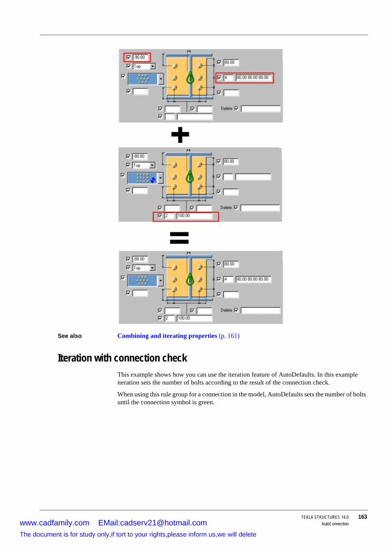
TEKLA STRUCTURES 14.0 163AutoConnection
See also Combining and iterating properties (p. 161)
Iteration with connection checkThis example shows how you can use the iteration feature of AutoDefaults. In this example iteration sets the number of bolts according to the result of the connection check.
When using this rule group for a connection in the model, AutoDefaults sets the number of bolts until the connection symbol is green.
www.cadfamily.com EMail:[email protected] document is for study only,if tort to your rights,please inform us,we will delete

164 TEKLA STRUCTURES 14.0AutoConnection
Creating iteration rules
First, create connection properties files for each number of bolts. See Editing connection properties (p. 158).
1. Click Detailing > AutoConnection > AutoDefaults Settings...2. Right-click the tree and select New rule group. Click the rule group and rename it to
"Iteration example".
3. Browse the tree and find connection 144. Right-click it and select Create additional rule sets....
4. Right-click the rule set and select Edit rule set..., to open the AutoDefault rules dialog box.
5. Change the Rule set name to "ITERATION".
6. Set Parameters file selection to Iterate until the connection symbol is green.
7. Click OK.
8. To create a rule set "2 bolts", right-click the first rule set and select Create additional rule sets....
9. Right-click the new rule set and select Edit rule set.... AutoDefault rules dialog box appears.
10. Select rule Secondary 1 depth and set the minimum and maximum depth values for two bolts.
11. Set Parameters file selection to Use combination of first parameters.
12. Click OK.
13. Right-click the connection properties file standard.j144, and click Select connection parameters.. to open the Attribute File List dialog box. Select the properties file for two bolts and click OK.
14. Repeat steps 8 to 13 for other rule sets.
Using rules and check together
You can use the connection check result when applying AutoDefaults with iteration. If a rule matches, but connection do not pass the check and symbol remains red, AutoDefaults continues testing other rules and properties until the connection symbol is green.
To apply a rule group and connection check for a connection:
The iteration rule forces Tekla Structures to tests sub rules until the connection symbol is green in the model.
www.cadfamily.com EMail:[email protected] document is for study only,if tort to your rights,please inform us,we will delete

TEKLA STRUCTURES 14.0 165AutoConnection
1. Open the connection properties dialog box.2. Load the <Defaults> properties.
3. Click General tab and set AutoDefaults Rule Group to the "Iteration example" you created.
4. Click Design type tab and set Connection check to Yes.
5. Enter the load from secondary members in the fields Shear, Tension, Moment.
6. Click OK to create the connection.
Checking To see which rules AutoDefaults used, right-click the connection symbol, and select Inquire.
To see which values AutoDefaults set, double-click the connection symbol to open the connection dialog box, select <AutoDefaults>, then click Load.
Reaction forces and UDLYou can save reaction forces:
• In the user-defined attributes of a part (for AutoConnection and AutoDefaults).• On the Design tab in the connection dialog box (for AutoDefaults).
Using reaction forces
When you use reaction forces in a rule and AutoDefaults is activate, Tekla Structures first searches for reaction forces in the corresponding connection’s properties. If they do not contain reaction forces, Tekla Structures searches the user-defined attributes of the secondary part of the connection. If Tekla Structures finds no forces there, you cannot use reaction force rules.
Shear force calculation
Shear force calculation is the exception. If you have not given any reaction force values, shear force is calculated using the UDL shear force routine. The UDL calculation is based on the AISC ASD Specification and is mainly intended for use with imperial units. It uses the yield stress value, profile dimensions, and UDL percentage to calculate the maximum allowable shear force. Tekla Structures compares the result with the Shear force rule in AutoDefaults.
• Yield stress is defined in the material catalog. • Profile dimensions come from the profile catalog.
• UDL percentage is taken either from the connection dialog box or from a variable.
UDL for AutoConnection
To switch on UDL calculation for AutoConnection:
1. On the Design tab in the connection dialog box, set the field Use UDL to Yes.2. Enter the UDL percentage in the UDL % field. If this field is blank, Tekla Structures uses a
default percentage (set using the variable XS_AUTODEFAULT_UDL_PERCENT).
UDL for AutoDefaults
To switch on UDL calculation for AutoDefaults:
• Set the variable XS_AUTOCONNECTION_USE_UDL to TRUE.• Use the variable XS_AUTODEFAULT_UDL_PERCENT to set the UDL percentage.
www.cadfamily.com EMail:[email protected] document is for study only,if tort to your rights,please inform us,we will delete

166 TEKLA STRUCTURES 14.0AutoConnectionwww.cadfamily.com EMail:[email protected]
The document is for study only,if tort to your rights,please inform us,we will delete

TEKLA STRUCTURES 14.0 167CNC
6 CNC
Introduction CNC (Computer Numerical Control) refers to the operation of a machine tool via motors, switches, and so on, with a computer controlling the manufacturing process. During the manufacturing process a machine tool or machining center cuts or shapes the piece of material.
In this chapter This chapter describes how to export CNC data from Tekla Structures models for use by machine tools. We explain how to export the data in different formats, such as DSTV, Peddimat, and DXF. We describe how to generate pop-marks in NC files. Pop marks are small holes that help the shop assemble individual parts to form an assembly. Then we explain how to generate hard stamps in NC files. Hard stamps are text marks that can contain various kind of information about parts. Finally we explain the plate nesting procedure.
Contents This chapter is divided into the following sections:
• NC files (p. 167)• DSTV (p. 174)
• DXF (p. 175)
• Peddimat (p. 176)
• Pop-marks (p. 178)
• Hard stamps (p. 181)
• Plate nesting (p. 183)
6.1 NC filesAfter you finish detailing in Tekla Structures, you can deliver the results to the next phase. You can use CNC links to send the information directly to automatic cutting and welding machines, or produce data for MIS systems (management information systems).
Formats Tekla Structures produces NC files in the following formats:
1. DSTV2. Peddimat
For DOS
www.cadfamily.com EMail:[email protected] document is for study only,if tort to your rights,please inform us,we will delete
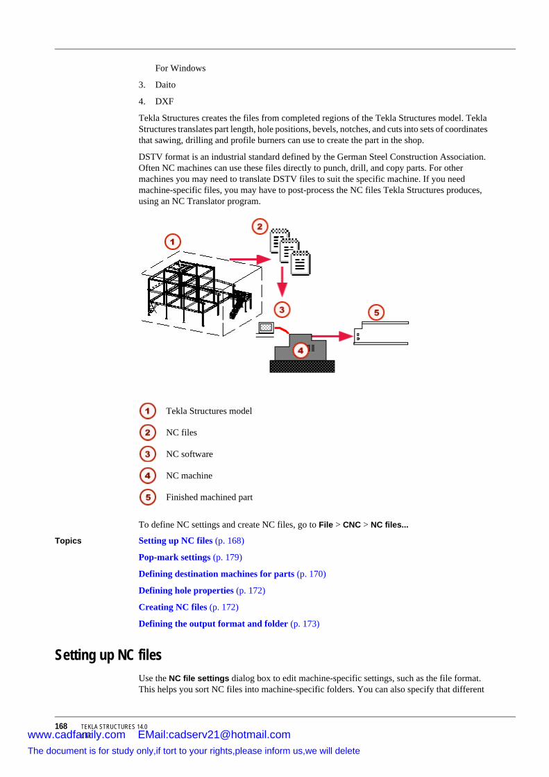
168 TEKLA STRUCTURES 14.0CNC
For Windows
3. Daito
4. DXF
Tekla Structures creates the files from completed regions of the Tekla Structures model. Tekla Structures translates part length, hole positions, bevels, notches, and cuts into sets of coordinates that sawing, drilling and profile burners can use to create the part in the shop.
DSTV format is an industrial standard defined by the German Steel Construction Association. Often NC machines can use these files directly to punch, drill, and copy parts. For other machines you may need to translate DSTV files to suit the specific machine. If you need machine-specific files, you may have to post-process the NC files Tekla Structures produces, using an NC Translator program.
To define NC settings and create NC files, go to File > CNC > NC files...
Topics Setting up NC files (p. 168)
Pop-mark settings (p. 179)
Defining destination machines for parts (p. 170)
Defining hole properties (p. 172)
Creating NC files (p. 172)
Defining the output format and folder (p. 173)
Setting up NC filesUse the NC file settings dialog box to edit machine-specific settings, such as the file format. This helps you sort NC files into machine-specific folders. You can also specify that different
Tekla Structures model
NC files
NC software
NC machine
Finished machined part
www.cadfamily.com EMail:[email protected] document is for study only,if tort to your rights,please inform us,we will delete

TEKLA STRUCTURES 14.0 169CNC
parts be machined by different NC machines, for example, plates by one machine, drilled parts by another, etc.
To set up NC files:
1. Click File > Export > CNC > Create NC Files...2. Click Add to open the NC file settings dialog box, which contains several tabs:
Tekla Structures saves the settings files in the attributes folder under the current model folder.
See also Pop-mark settings (p. 179)
Defining destination machines for parts (p. 170)
Creating NC files (p. 172)
Fittings affect NC data (p. 174)
NC file settings
Plates
Plasma cut
Drilled parts
Tab Description More information
Files and part selec-tion
Output format, the profile types that machines can handle, and maximum hole diameters
Defining the output format and folder (p. 173)
Defining selection criteria (p. 170)
Holes and cuts Slot conversion options, standard tooling for Peddimat
Defining hole prop-erties (p. 172)
Defining Peddimat standard tooling (p. 177)
Hard stamp Hard stamp options Hard stamp proper-ties (p. 181)
www.cadfamily.com EMail:[email protected] document is for study only,if tort to your rights,please inform us,we will delete

170 TEKLA STRUCTURES 14.0CNC
Defining destination machines for partsTo define the limits of an NC machine:
1. Open the NC file settings dialog box and go to the Files and Part selection tab.2. In the Selection criteria for parts section, use the Maximum size and Profile type fields
to define the limits of the NC machine, for parts and profile types. Larger parts will be sent to the next machine.
Tekla Structures uses DSTV standard names for profile types: I, U, L, M, R, B, CC, T, SO. See also Profile type (p. 171).
Inner corners shape
Use the options in the Holes and cuts tab, Inner corner shape list box to define the shape of the inner contour, which can be radial, tangential or square. Inner contours are always rounded. Enter a radius for rounding in the Radius field.
See also Creating NC files (p. 172)
Defining selection criteriaEach NC file setting is meant for one NC machine. The selection criteria determine the part types and maximum sizes the machine is meant to or able to process.
To define the selection criteria:
1. Click File > Export > CNC > Create NC Files... The NC Files dialog box appears. 2. Select a setting from the list and click Edit.... If the list is empty, click Add... to create new
settings.
3. In the NC file settings dialog box, define the selection criteria.
www.cadfamily.com EMail:[email protected] document is for study only,if tort to your rights,please inform us,we will delete

TEKLA STRUCTURES 14.0 171CNC
Maximum sizeThe maximum size options define the maximum length, width, and height of the parts the machine can handle. Larger parts are sent to other machines.
Profile typeThe machine can handle all the profile types which have the option Yes in the Profile type list. Profile types are named according to the DSTV (p. 174) standard:
DSTV profile type Description
I I profilesU U and C profilesL Angle profilesM Rectangular tubesR Round bars and tubesB Plate profilesCC CC profiles
www.cadfamily.com EMail:[email protected] document is for study only,if tort to your rights,please inform us,we will delete

172 TEKLA STRUCTURES 14.0CNC
Round tubes By default Tekla Structures unwraps round tubes as plate profiles and uses the plate profile type B in the NC file header data. To change this, use the variable XS_TUBE_UNWRAP_USE_PLATE_PROFILE_TYPE_IN_NC.
Maximum size of holesThe Maximum size of holes list defines how large holes the machine is able to drill. Parts containing larger holes are sent to other machines. The hole size is connected to material thickness (or plate thickness). Each row contains the maximum hole diameter and material thickness. Row 60 45 means that when the material thickness is 45 mm or smaller, holes of a diameter of 60 mm and smaller will be drilled. The remaining rows serve the same purpose.
Defining hole propertiesOpen the NC file settings dialog box and go to the Holes and cuts tab. You have the following options:
Slotted holes Options that define slotted holes:
• Ignore slots: deletes slotted holes • A single hole in the center of the slot: drills a single hole in the center of the slotted hole
• Four small holes, one at each corner: drills 4 smaller holes, one at each corner
• Internal contours: flame-cuts the slots as internal contours
• Slots: leaves slots as they are.
Maximum hole diameter
Holes and slotted holes that are larger than the maximum hole diameter are manufactured as internal contours.
Maximum size of holes
Use the Maximum size of holes section of the Files and part selection tab to define the maximum hole diameter for different plate thicknesses.
Once you have finished defining NC settings, click OK to save your changes and close the NC file settings dialog box.
See also Creating NC files (p. 172)
Creating NC filesTo create NC files:
If necessary, define the NC file settings. See Setting up NC files (p. 168).
1. Go to the NC files dialog box, or click File > Export > CNC > Create NC Files... to open it.
T Tee shaped profilesSO Z profiles and all the other
types of profile
The DTSV standard does not support curved beams, so Tekla Structures does not support them, either.
DSTV profile type Description
www.cadfamily.com EMail:[email protected] document is for study only,if tort to your rights,please inform us,we will delete

TEKLA STRUCTURES 14.0 173CNC
2. Select the Create checkboxes in the NC file settings section to indicate which NC file settings to use.
3. Against the Create files for field, select a checkbox to indicate the parts you want to create NC files for:
• All parts• Selected parts
4. Click Create to create the NC files.
See also Setting up NC files (p. 168)
Defining the output format and folder (p. 173)
Defining the output format and folderFormat Use the options in NC file settings > Files and part selection, File format field to select the
file format. For more information on formats, see:
• DSTV (p. 174)• DXF (p. 175)
• Peddimat (p. 176)
Folder By default Tekla Structures creates NC files in the current model folder. To change this:
1. Go to the Files and part selection tab.2. Click the Browse button next to the File location field.
3. In the Set file location dialog box, locate the correct folder. If the folder does not exist, use the Create New Folder button to create it.
4. Click OK. Tekla Structures displays the folder path in the File location field.
Relative paths You can also enter a folder name or a relative path directly in the File location field.
The following table shows where the NC files are created with different values of the File location field, when the variable XS_MIS_FILE_DIRECTORY is set to C:\NC.
Tekla Structures does not create NC files for curved beams.
You must select a file in the destination folder to get the folder selected in the File location field. It does not matter which file you select. If there are no files in the folder, create one there, for example an empty .txt file.
File location NC files are created to
C:\NC.\ C:\NC\ModelName.\MyFiles C:\NC\ModelName\MyFilesC:\TEMP C:\TEMP
www.cadfamily.com EMail:[email protected] document is for study only,if tort to your rights,please inform us,we will delete

174 TEKLA STRUCTURES 14.0CNC
The following table shows where the NC files are created with different values of the File location field, when the variable XS_MIS_FILE_DIRECTORY is NOT set.
See also Setting up NC files (p. 168)
Creating NC files (p. 172)
6.2 DSTVDSTV format is an industrial standard defined by the German Steel Construction Association.
The data for NC output comes from the model. We recommend that you complete detailing and create drawings prior to producing NC output.
To create DSTV files:
1. Select the parts from which you want to create NC files. 2. Click File > Export > CNC > Create NC Files... to display the NC files dialog box.
3. Click Add to display the NC file settings dialog box.
4. Go to the File format field on the Files and part selection tab and select DSTV.
5. In the Settings name field, enter a distinctive name for the settings.
6. Click OK to save your settings and close the NC file settings dialog box.
7. Go to the NC File settings section of the NC files dialog box and select the DSTV file settings you created.
8. Select the Selected parts checkbox.
9. Click Create.
This will create nc1 files for all selected parts and put them in the model folder. The filename consists of a position number and the extension nc1.
See also Pop-marks (p. 178)
Setting up NC files (p. 168)
Defining the output format and folder (p. 173)
Fittings affect NC dataWhen creating NC files in DSTV format, the method you use to cut the end of the beam affects beam length in the NC file. The illustration below shows the default length when you have fitting and line cuts.
File location NC files are created to
model folder.\ model folder.\MyFiles model folder\MyFilesC:\TEMP C:\TEMP
www.cadfamily.com EMail:[email protected] document is for study only,if tort to your rights,please inform us,we will delete

TEKLA STRUCTURES 14.0 175CNC
The overall length of a beam will be the fitted net length of the beam. This means that Tekla Structures always takes the fitting into account when calculating beam length. For lines, polygons, or part cuts, the cut does not affect beam length, but the overall length in the NC/DSTV file will be the gross (initial modeled) length of the beam.
Shortest length If you want to use the shortest possible length in the NC file, you can change this so that the cut affects part length:
1. Open the Advanced options dialog and enter 1 in the Value field for variable XS_DSTV_NET_LENGTH in the CNC category.
2. Restart Tekla Structures.
Net and cross length
If you want to include both net and cross length into NC file header data, set the variable XS_DSTV_PRINT_NET_AND_GROSS_LENGTH.
6.3 DXFThis section explains how to create NC data in 2D DXF format.
Preconditions Before running a DXF conversion, you must first create NC files in DSTV format. For more information, see DSTV (p. 174).
You can then use a separate Tekla Structures program, dstv2dxf.exe to convert the files to DXF format. The program converts NC DSTV files to 2D DXF files. Tekla Structures only writes one side of a part (front, top, back or bottom) to file, so this export format is most suited to plates.
Topics Converting DSTV files to DXF (p. 176)
Fitting affects the length
Line cut does not affect length
Line cut
Fitting
www.cadfamily.com EMail:[email protected] document is for study only,if tort to your rights,please inform us,we will delete

176 TEKLA STRUCTURES 14.0CNC
Converting DSTV files to DXF The most convenient way to convert DSTV files to DXF files is to use the macro Convert_DSTV2DXF, located in Tools > Macros....
You can also use a dstv2dxf converter to convert DSTV files to DXF files.
To start the conversion:
1. Save the *.nc1 file(s) in the dstv2dxf folder.2. Double-click the suitable dstv2dxf conversion .bat file (for example
tekla_dstv2dxf_metric_conversion.bat) in the TeklaStructures/ 14.0/nt/dstv2dxf folder.
3. The converter converts the files to dxf format in the same folder.
6.4 PeddimatThis section explains how to create NC files in Peddimat format. The files you create can be downloaded straight to the CNC machinery software.
Topics Creating NC files in Peddimat format (p. 176)
Output formats for Peddimat (p. 177)
Setting up NC files (p. 168)
Defining Peddimat standard tooling (p. 177)
Creating NC files in Peddimat formatTo create NC files in Peddimat format:
1. Click File > Export > CNC > Create NC Files... to display the NC files dialog box.2. Click Add to display the NC file settings dialog box.
3. Go to the File format field on the Files and part selection tab and select the approriate Peddimat option.
For more information on the Peddimat options, see Output formats for Peddimat (p. 177).
1. In the Settings name field, enter a distinctive name for the file. 2. Click OK to save your settings and close the NC file settings dialog box.
3. Go to the NC files dialog box, select the Peddimat file settings you created.
4. Select the All parts checkbox.
5. Click Create.
See also Output formats for Peddimat (p. 177)
Defining Peddimat standard tooling (p. 177)
If you need to adjust the conversion settings, edit the settings in the file dstv2dxf.def and restart the conversion.
For more information on settings, see the document DEF File Description.pdf in the same folder.
www.cadfamily.com EMail:[email protected] document is for study only,if tort to your rights,please inform us,we will delete

TEKLA STRUCTURES 14.0 177CNC
Output formats for PeddimatTo set the Peddimat format, go to NC file settings > File and part selection. This table shows the available output formats for NC files for Peddimat machines:
See also Creating NC files in Peddimat format (p. 176)
Defining Peddimat standard tooling (p. 177)
Defining Peddimat standard toolingYou can define standard tooling before creating NC files in Peddimat format. Standard tooling minimizes the number of tool changes in the workshop.
To define standard Peddimat tooling diameters, go to the Holes and cuts tab in the NC file settings dialog box.
Example The following example first shows the tooling from Peddimat for Windows, then the settings in Tekla Structures:
To ensure that the part origin is calculated correctly, even if the part is coped and mitered, select Calculate part origin without copes on the Holes and cuts tab.
See also Setting up NC files (p. 168)
Option Description
Peddimat for Windows Supports standard Peddimat for Windows
Peddimat for Windows (one cope file)
Supports Peddimat for Windows with a single file containing all copes
Peddimat for Windows (two cope files)
Peddimat for Windows with two cope files. The copes at the right and left ends of the part are written to two separate files
Peddimat for Windows (without copes)
Peddimat for Windows without cope files
Peddimat for DOS Supports Peddimat for DOS
www.cadfamily.com EMail:[email protected] document is for study only,if tort to your rights,please inform us,we will delete

178 TEKLA STRUCTURES 14.0CNC
6.5 Pop-marksTekla Structures can generate pop-marks in NC files to help position parts that will be manually welded to the main part. Pop-marks are usually made using a drilling machine.
To include pop-marks in the NC file, you have to define a list of part names to pop-mark in the Pop-mark settings dialog box. To access the dialog box, select File > Export > CNC > Create NC Files... > Pop-marks...
You can save the pop-mark settings in a .ncp file, which Tekla Structures saves in the attributes folder under the current model folder by default. Tekla Structures only creates pop-marks for parts for which you have defined properties.
The Pop-marking options tab in the Pop-mark settings dialog box contains options for controlling the settings for marks in the back of parts, and other additional options. For more information on these settings, see Pop-marking options (p. 180).
To have Tekla Structures create pop-marks when creating NC files, select the check box in NC files > NC file settings: > Pop-marks.
Creating pop-marksTo create pop-marks in an NC file:
1. Define and save the pop-mark settings in the Pop-mark settings (p. 179) dialog box.2. To display pop-marks in a model view, select Pop-marking options > Show pop-marks
in the model.
3. Create the NC files. Remember to select the Pop-marks checkbox in the NC files dialog box.
Pop-marks are written in the NC file BO block as 0 mm diameter holes.
Tekla Structures displays thick red lines for each pop-mark pair in the model view which was last updated.
Pop-marking also affects numbering.
For example, if two parts have different pop-marks, or one part has pop-marks and the other one does not, Tekla Structures gives the parts different numbers.
See What affects numbering.
www.cadfamily.com EMail:[email protected] document is for study only,if tort to your rights,please inform us,we will delete

TEKLA STRUCTURES 14.0 179CNC
Topics Pop-mark settings (p. 179)
Pop-marking options (p. 180)
Pop-mark settingsThe Pop-mark settings dialog box includes pop-mark settings that define:
• Which parts are pop-marked• Where the pop-marks are created
Tekla Structures saves the settings file .ncp in the attributes folder under the current model folder.
Tekla Structures looks for this file in the current model folder, then uses the standard folder search order. See Folder search order (p. 94).
You can use wildcards (* ? [ ] ) in the Main part name and Secondary part name fields in the Pop-mark settings dialog box. For example, HE* matches all parts with a profile name that begins with the characters "HE". For more information on wildcards, see Using wildcards.
Pop-mark settings
The order of the lines in the dialog box is important. Tekla Structures uses the match it finds, so you should put the most limiting definition first, and the most generic one last.
Option Description
Main part profile type
The main part profile types to pop-mark. The list box contains profile types corresponding to the DSTV standard.
Main part name The main part profile names to pop-mark. You can enter several part names separated by commas.
Sec part profile type Secondary part profile type.Secondary part name
Secondary part name. You can enter several part names separated by commas.
www.cadfamily.com EMail:[email protected] document is for study only,if tort to your rights,please inform us,we will delete

180 TEKLA STRUCTURES 14.0CNC
Pop-marking optionsOptions for marks in the back
Use the options for marks in the back face of parts to set the NC machine to:
• Rotate the part if there are items on the back of it and none on the front.• Drill the pop-marks through to the back, if there are no other items there. The hole diameter
must also be defined.
• Rotate the part and drill pop-marks through to the back if there are no items on the front but some in the back or more pop-marks on the back than on the front. The hole diameter must also be defined.
Other options • No pop-marks on overlapping holes deletes a pop-mark if a hole overlaps it.• Pop-mark centres of studs adds pop-marks to the center point of studs. Uncheck this
option to prevent studs from being pop-marked.
• Show pop-marks in the model displays pop-marks in model views.
Pop-mark location Defines how the secondary part is projected onto a main part.
• Left side: The left side of the secondary part is marked on the main part. The left side is the side of the secondary part that points in the negative direction of the main part local coordinate system.
• Right side: The right side of the secondary part is marked on the main part.
• Both sides: combines Left side and Right side.
• Center: Center of the secondary part.
• Left side holes: Marks the main part with the hole positions on the left side of the secondary.
• Right side holes: Marks the main part with the hole positions on the right side of the secondary.
• Both side holes: combines Left side holes and Right side holes.
• Middle line: Marks two points on the middle line of the secondary part x axis.
Edge distance Minimum distance from a pop-mark to the edge of the main part. Tekla Structures does not create pop-marks inside this distance. If a pop-mark is inside the defined edge distance, Tekla Structures moves it (with the exception of Center).
Move to flange Moves pop-marks to the main part flange.Secondary pop-marks
Creates pop-marks into secondary parts.
Option Description
www.cadfamily.com EMail:[email protected] document is for study only,if tort to your rights,please inform us,we will delete

TEKLA STRUCTURES 14.0 181CNC
Examples The following line in the Pop-mark settings dialog box tells Tekla Structures to mark the center point of all round secondary profiles on a main part, and not to create pop-marks closer than 10 mm to the main part edge.
The following line in the Pop-mark settings dialog box tells Tekla Structures to project the hole locations in secondary plates onto a main part:
6.6 Hard stampsTekla Structures can output DSTV files that include hard stamps for the workshop to apply to main and secondary parts. Hard stamps are text marks that contain information about parts and assemblies, for example, project and lot number, phase, or part and assembly position.
Creating hard stampsTo include hard stamps in a DSTV file:
1. In the NC file settings dialog box, go to the Hard stamps tab.2. Select the checkbox Create hard stamp.
3. In the Available elements list, select the elements to include in the hard stamp.
4. Click OK to save your settings and close the NC file settings dialog box.
Example This example shows a hard stamp that contains the elements Phase, Part position, Material, and Text.
See also For more information on hard stamp settings, see Hard stamp properties (p. 181), XS_SECONDARY_PART_HARDSTAMP (p. 383) and XS_HARD_STAMP_BY_ORIENTATION_MARK (p. 345).
Hard stamp propertiesUse the options on the Hard stamp tab to define the properties of hard stamps on main and/or secondary parts, including:
• Information contained in hard stamps (p. 182)• The order in which the different elements appear
www.cadfamily.com EMail:[email protected] document is for study only,if tort to your rights,please inform us,we will delete

182 TEKLA STRUCTURES 14.0CNC
• Text height and case
• Position of hard stamps (p. 182)
• Hard stamps for secondary parts (p. 182)
Information contained in hard stampsYou can include the following information in hard stamps:
If you include part position and/or assembly position in the hard stamp, they affect the DSTV filename as follows:
• Part position: P1.nc1, P2.nc1• Assembly position: A1.nc1, A2.nc1
• Assembly and part position: A1-P1.nc1, A2-P2.nc1
Position of hard stampsUse the options in the Position along the part and Position in depth of part list boxes to define the position of hard stamps on parts. The options are:
• Middle, Middle • Middle, Left
• Middle, Right
• Bottom, Middle
• Bottom, Left
• Bottom, Right
• Top, Middle
• Top, Left
• Top, Right
Hard stamps for secondary partsTo create hardstamps also for secondary parts, set XS_SECONDARY_PART_HARDSTAMP to TRUE in Tools > Advanced options > CNC.
Element Description
Project number Adds the project number to the hard stamp.Lot number Adds the lot number to the hard stamp.Phase Adds the phase number to the hard stamp.Part position Prefix and position number of the partAssembly position Prefix and position number of the assemblyMaterial The material of the part.Finish The type of finish.User-defined attribute Adds a user-defined attribute (user fields 1-4)
to the mark.Text Opens a dialog box where you can add user-
defined text to the hard stamp.
www.cadfamily.com EMail:[email protected] document is for study only,if tort to your rights,please inform us,we will delete

TEKLA STRUCTURES 14.0 183CNC
6.7 Plate nestingTekla Structures Plate Nesting finds the best layout pattern for cutting plates from the available metal sheets. Tekla Structures Plate Nesting uses DSTV NC files to create the nesting tasks and the nesting layout. The results are DXF drawings, which you can view using the Result Viewer.
You need to have the Plate Nesting module acquired in your Tekla Structures license entitlement in order to do plate nesting. The plate nesting functionality is automatically available in Tekla Structures if acquired.
Phases Plate nesting has following phases:
1. Create NC files. See DSTV (p. 174).2. Creating nesting tasks (p. 183)
3. Editing nesting tasks (p. 183)
4. Nesting tasks (p. 185)
5. Viewing nesting results (p. 186)
Creating nesting tasksFirst you need to create NC files of the parts to nest. For more information, see DSTV (p. 174).
Then follow these steps:
1. Click File > Export > CNC > Define Nesting Tasks... to display the Tekla Structures Plate Nesting - DSTV2TASK dialog box.
2. Set DSTV Directory to point to the NC files folder.
3. Enter a name for the task group.
4. Select the NC files you want to nest from the upper list, then click Add.
5. Click Start.
6. Tekla Structures prompts you ...directory does not exist. This is just for information. Answer OK to these prompts.
7. To preview the parts, highlight them on the Created Parts list.
8. Close the dialog box.
Tekla Structures groups the selected NC files into nesting tasks. Each task consists of parts with the same material thickness and grade.
Next step Editing nesting tasks (p. 183)
Editing nesting tasksThis is the second phase in plate nesting, where you set the manufacturing information or nesting tasks.
Tekla Structures does not create hard stamps for plates.
www.cadfamily.com EMail:[email protected] document is for study only,if tort to your rights,please inform us,we will delete

184 TEKLA STRUCTURES 14.0CNC
1. Select File > Export > CNC > Edit Nesting Tasks to display the Tekla Structures Plate Nesting - TaskEdit dialog box.
2. Click Browse to select the task.
3. Enter additional manufacturing information.
4. To define the stock required, click Define Stocks. For more information, see Defining stocks (p. 184).
5. To preview the plates in the task, click Define Parts.
6. To save the settings, click Save.
7. Click Yes, when Tekla Structures prompts you that the task file already exists. The Save Task Information dialog box appears.
8. Click OK to save the selected settings for the other tasks in the group.
Next step Nesting tasks (p. 185)
Task propertiesThe following illustration shows cutting cap and edge allowances:
Cutting Cap defines the cutting gap between nested parts to allow for tool size.
Edge allowance defines the clearance around the edge of a stock sheet to allow for trimming or clamping.
Defining stocksYou need to define the stock to use for nesting tasks. See Editing nesting tasks (p. 183). The stock sheet information includes the number of distinct stocks, the sheet size, and quantity.
1. Click Define stock to display the Stock sheet specification dialog box.This is where you define the stock sheet information, including the number of distinct stocks. You also need to prioritize stock sizes. See also Stock properties (p. 185).
Left
Cutting Cap
Bottom
Bridge width
www.cadfamily.com EMail:[email protected] document is for study only,if tort to your rights,please inform us,we will delete

TEKLA STRUCTURES 14.0 185CNC
2. To define which stock to use, select a stock from the Available Stocks list, then click Add to display the Stock specification - Add dialog box.
3. Set the stock properties and click OK. The stock appears in the Selected Stocks list.
4. After selecting the stock you require, click OK to return to the TaskEdit dialog box.
Stock propertiesYou can define the following properties for stock:
• Width and LengthThe width and length of the stock sheet. In the imperial version of Tekla Structures, you can either enter feet and inches, or just inches.
• QuantityQuantity of stock sheets of a particular size to use for the task. You can use a maximum of 9999 for each stock size.
• StretchableYou can use this option for tasks nesting more than one part. For stock sheets in reels or rolls, Tekla Structures Plate Nesting can stretch the sheet length to best fit all the parts.
• PriorityDefines the order in which Tekla Structures Plate Nesting uses the stock sheets. 1 has the highest priority, 99 has the lowest.
Nesting tasksAfter you create tasks and edit the plates, you can run the nesting program. In this phase, Tekla Structures Plate Nesting optimizes the layout of plates on the stock sheets and saves the layout in DXF files.
1. Click File > CNC > Plate Nesting > Nesting… to display the Tekla Structures Plate Nesting - NestPRO dialog box.
2. Select the tasks to nest, then click Add.
3. Click Start to start the nesting process.
4. When the nesting process ends, close the dialog box.
www.cadfamily.com EMail:[email protected] document is for study only,if tort to your rights,please inform us,we will delete
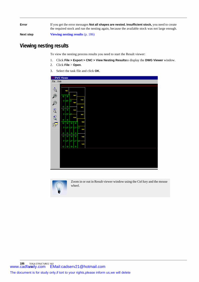
186 TEKLA STRUCTURES 14.0CNC
Error If you get the error messages Not all shapes are nested. Insufficient stock, you need to create the required stock and run the nesting again, because the available stock was not large enough.
Next step Viewing nesting results (p. 186)
Viewing nesting resultsTo view the nesting process results you need to start the Result viewer:
1. Click File > Export > CNC > View Nesting Resultsto display the DWG Viewer window.2. Click File > Open.
3. Select the task file and click OK.
Zoom in or out in Result viewer window using the Ctrl key and the mouse wheel.
www.cadfamily.com EMail:[email protected] document is for study only,if tort to your rights,please inform us,we will delete

TEKLA STRUCTURES 14.0 187Import and export
7 Import and export
Introduction Tekla Structures includes several tools you can use to import and export models and the information they contain. You can:
• Import data from other software and use it to create models and reports.• Export data from Tekla Structures to use in manufacturing information systems and
structural analysis programs.
In this chapter This chapter explains how to import and export data in Tekla Structures, and describes the formats and tools available. The first section covers the basics of import and export. The final two sections give more details about the import and export options.
Assumed background
You should have some experience of modeling in Tekla Structures.
Contents This chapter is divided into the following sections:
• Import and export basics (p. 187)• Conversion files (p. 192)
• Importing models (p. 194)
• Exporting files (p. 219)
• Reference models (p. 271)
• Tekla WebViewer (p. 278)
7.1 Import and export basicsThis section gives you an overview of importing and exporting data in Tekla Structures, as well as step-by-step instructions. It includes the different import and export formats available in Tekla Structures. It also describes the conversion files you can use to import profiles and materials.
Topics Using import and export (p. 188)
Available formats (p. 188)
www.cadfamily.com EMail:[email protected] document is for study only,if tort to your rights,please inform us,we will delete

188 TEKLA STRUCTURES 14.0Import and export
Re-importing a model (p. 197)
Revision control options (p. 197)
Creating reports of import (p. 198)
Using import and exportYou can use import and export in Tekla Structures for several purposes:
• Import 2D or 3D models created by other software, then detail them using Tekla Structures. Once detailing is complete, export the model and return it to the architect or engineer for review.
• Export Tekla Structures models to use in analysis and design (several formats). Then import the design and analysis results back to the Tekla Structures model.
• Export data for use in the fabrication phase:
• You can export CNC data (Computer Numerical Control) for use by automated cutting, boring and welding machinery,
• MIS (Manufacturing Information Systems) so that fabricators can track project progress.
Available formatsThe following tables list many of the different software and formats you can use in Tekla Structures to import and export data.
Locate the software in the first column (Software). Read across the columns to locate import and export tools (for example, DWG/DXF, FEM). Each cell displays the import and export formats (for example, Calma, XML, SDNF).
You may also be able to exchange data with software not listed here.
Importing into Tekla Structures
Import tool –>
DWG/DXF FEM CIMsteel CAD OtherSoftware
ArchiCAD 2D, 3D XMLAutoCAD 2D, 3DBUS BUSCadmatic 2D, 3DCalma CalmaESA Prima WIN
DSTV
ETABS CIS2 SDNF PDMS (only straight profiles)
www.cadfamily.com EMail:[email protected] document is for study only,if tort to your rights,please inform us,we will delete

TEKLA STRUCTURES 14.0 189Import and export
FabTrol CIS2 FabTrol XML, SteelFab
FrameWorks SDNF DGN (as Reference models (p. 271))
GT Strudl CIS2 MicasPlusIFC schema edition
IFC2X, IFC2X2, IFC2X3 (as Reference models (p. 271))
MicasPlus MicasPlusMicroStation DGN (as
Reference models (p. 271))
ModelDraftMultiframe 2D, 3DNastran STAADPDMS SDNF DGN (as
Reference models (p. 271))
PDS DGN (as Reference models (p. 271))
Plantview PlantviewPowerFrame DSTVRAMSteel CIS2 Revit IFC 2X3ROBOT DSTV CIS2 RSTAB 2D, 3D DSTV STPSACS SACS SDNFSAP 2000 SDNF
PDMS (only straight profiles)
SDS/2 CIS2 SDNFSESAM SACSS-frame 2D, 3D S-frame
Import tool –>
DWG/DXF FEM CIMsteel CAD OtherSoftware
www.cadfamily.com EMail:[email protected] document is for study only,if tort to your rights,please inform us,we will delete

190 TEKLA STRUCTURES 14.0Import and export
Exporting from Tekla Structures
SAP2000 SDNFSmartPlant CIS2 DGN (as
Reference models (p. 271))
SPACE GASS
SDNF
Speedikon HLISTAAD 2D, 3D STAADStan 3d Stan 3dStruCad SDNFStructural for MicroStation TriForma
DGN (as Reference models (p. 271))
TriForma CIS2
Export tool –>
DWG/DXF FEM CIMsteel CAD OtherSoftware
ArchiCAD 2D, 3D XMLAutoCAD 2D, 3DCadmatic XMLCalma CalmaFabTrol CIS2
(Manufac-turing)
MIS
FrameWorks Plus
CIS2
EJE MISEPC MISETABS FEM CIS2 SDNF
PDMS (only straight profiles)
ESA Prima WIN
DSTV
Eureka LPM CIS1 & 2Fabtrol CIS2FrameWorks CIS1 & 2 SDNF, PML 3D DGNGT Strudl STAAD
Import tool –>
DWG/DXF FEM CIMsteel CAD OtherSoftware
www.cadfamily.com EMail:[email protected] document is for study only,if tort to your rights,please inform us,we will delete
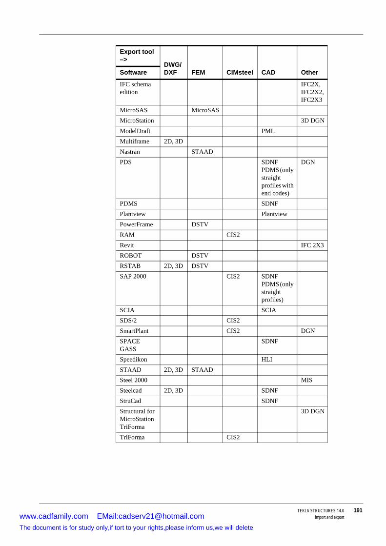
TEKLA STRUCTURES 14.0 191Import and export
IFC schema edition
IFC2X, IFC2X2, IFC2X3
MicroSAS MicroSASMicroStation 3D DGNModelDraft PMLMultiframe 2D, 3DNastran STAADPDS SDNF
PDMS (only straight profiles with end codes)
DGN
PDMS SDNFPlantview PlantviewPowerFrame DSTVRAM CIS2Revit IFC 2X3ROBOT DSTVRSTAB 2D, 3D DSTVSAP 2000 CIS2 SDNF
PDMS (only straight profiles)
SCIA SCIASDS/2 CIS2SmartPlant CIS2 DGNSPACE GASS
SDNF
Speedikon HLISTAAD 2D, 3D STAADSteel 2000 MISSteelcad 2D, 3D SDNFStruCad SDNFStructural for MicroStation TriForma
3D DGN
TriForma CIS2
Export tool –>
DWG/DXF FEM CIMsteel CAD OtherSoftware
www.cadfamily.com EMail:[email protected] document is for study only,if tort to your rights,please inform us,we will delete

192 TEKLA STRUCTURES 14.0Import and export
7.2 Conversion filesAbout conversion files
Conversion files map Tekla Structures profile and material names with names used in other software. Conversion files are simple text files, containing the Tekla Structures name in the first column, and the name used in the other software package in the second column. Columns are separated by a space. All parametric profiles must be entered in the profile conversion file.
You can use the same conversion file both when importing and exporting models. You can specify the location of conversion files in most of the import and export tools.
• If you leave the field blank, Tekla Structures looks for the conversion file defined by the variable XS_PROFDB, in Tools > Options > Advanced Options... > File Locations.
• If you enter a conversion file name without a path, Tekla Structures searches for the file in the current model folder.
Tekla Structures includes several conversion files in the standard installation, and you can also create your own. See Creating conversion files (p. 192). Conversion files are located in the \environments\environment\profil folder. All conversion files have the extension cnv.
Converting twin profilesTekla Structures also includes twin profile conversion files. Tekla Structures reads the twin profile conversion file before the profile conversion file, so you should include the profiles from the original model in the import.
The twin profile conversion file is a text file containing the profile prefix (characters only) and the distance between the profiles in mm, separated by a space character. Tekla Structures converts all profiles with the specified prefix to twin profiles.
Additional information
Creating conversion files (p. 192)
Locating conversion files (p. 193)
Sample conversion files (p. 193)
Troubleshooting (p. 193)
Importing models (p. 194)
Creating conversion filesYou can also create your own conversion files.
To create a new conversion file:
1. Open an existing conversion file using any text editor (e.g. Wordpad). See Locating conversion files (p. 193).
www.cadfamily.com EMail:[email protected] document is for study only,if tort to your rights,please inform us,we will delete

TEKLA STRUCTURES 14.0 193Import and export
2. Use Save as to give the file a new name.
3. Edit the file, entering profile names recognized by Tekla Structures in the first column, and the corresponding name recognized by the other software in the second column. See Sample conversion files (p. 193).
Locating conversion filesStandard conversion files are located in the profil folder for the environment you are using (for example, \environments\usimp\profil). Tekla Structures searches for profile conversion files:
• In the current model folder• Using the path indicated by the variable XS_PROFDB in Tools > Options > Advanced
Options... > File Locations.
Sample conversion filesHere are some sample conversion files for reference:
TroubleshootingIf you have problems importing a model, check the following:
! Profile name conversion Tekla Structures -> SDNF ! ! If Converted-name does not exist, it will be the same! as Tekla Structures-name.
! Tekla Structures-nameConverted-name
C10X15.3C10X15.3 C10X20C10X20 C10X25C10X25 C10X30C10X30 C12X20.7C12X20.7 C12X25C12X25 C12X30C12X30 C15X33.9C15X33.9 C15X40C15X40 C15X50C15X50 C3X4.1 C3X4.1
! Profile name conversion Tekla Structures -> DSTV ! ! If Converted-name does not exist, it will be the same! as Tekla Structures-name.
! Tekla Structures-name Converted-name
C10X15.3 C10X15.3 C10X20 C10X20 C10X25 C10X25 C10X30 C10X30 C12X20.7 C12X20.7 C12X25 C12X25
www.cadfamily.com EMail:[email protected] document is for study only,if tort to your rights,please inform us,we will delete

194 TEKLA STRUCTURES 14.0Import and export
• Are there any error messages in the Tekla Structures log file? • Is the input file located in the current model folder?
• Are there are blank material definitions (" ", empty quotation marks) in your input file?
• In your input file, see if profile position strings contain a space character (e.g. "Hand Rail" or "Thread 13").
Examples Errors and corrections are highlighted in the following examples.
7.3 Importing modelsThis section explains the basics of how to import a model created by a different system into Tekla Structures. It also contains details of the specific information you need to include for each type of import file.
Topics Import tools (p. 194)
Overview of importing models (p. 195)
Re-importing a model (p. 197)
Creating reports of import (p. 198)
Import toolsUse the following tools to import different file types into Tekla Structures:
• Importing DWG/DXF files (p. 199)• FEM import (p. 202)
• CAD import (p. 200)
• CIS import (p. 199) (CIMsteel)
• Steelfab import (p. 215)
• Fabtrol XML import (p. 215)
Incorrect input file00100782 4 0 2 "brace" "Tread 4" 1"TREAD4.5" "" 0.000000 0 00.000000 1.000000 0.000000 16.250000 13.154267 3.857143 15.500000 13.154267 3.857143 0.000000 0.0000000.000000 0.0000000.000000 0.000000 0.000000 0.000000 0.000000 0.0000000 0 0 0 0 0 0 0 0 0 0 0
Correct input file00100782 4 0 2 "brace" "Tread_4" 1"TREAD4.5" "A36" 0.000000 0 00.000000 1.000000 0.000000 16.250000 13.154267 3.857143 15.500000 13.154267 3.857143 0.000000 0.0000000.000000 0.0000000.000000 0.000000 0.000000 0.000000 0.000000 0.0000000 0 0 0 0 0 0 0 0 0 0 0
www.cadfamily.com EMail:[email protected] document is for study only,if tort to your rights,please inform us,we will delete

TEKLA STRUCTURES 14.0 195Import and export
• S-Frame import (p. 216)
• MicasPlus import (p. 216)
• Eureka LPM import (p. 216)
• Model dump import (p. 206)
• ASCII import (p. 206)
• ASCII format description
• Attribute import (p. 211)
Overview of importing modelsThese steps explain the basics of how to import a model into Tekla Structures. You will also need to refer to other sections for information specific to a particular import type. See also Import tools (p. 194).
To import a model:
1. Open Tekla Structures and create a new model. 2. Click File > Import.
3. Select any of the following options FEM, CIMSteel, CAD, or Other, to open the New import model dialog box.
4. Select the import type in the Type list box. See also Re-importing a model (p. 197).
5. Enter a name for the import model in the Name field. The default name is import model. Tekla Structures uses the model name for revision control. For more information, see Revision control options (p. 197).
6. Click Properties... to open a dialog box where you can define the settings for the import file type you selected.
7. On the Parameters tab, enter a file name in the Input file field, or use the browse (...) button to set the path to the file.
8. Enter values in the Origin fields if you want to import the file to a specific origin.
9. Click OK to return to the New import model dialog box.
Finishing the importTo complete the import:
1. Click OK to open the Import models dialog box.
www.cadfamily.com EMail:[email protected] document is for study only,if tort to your rights,please inform us,we will delete

196 TEKLA STRUCTURES 14.0Import and export
2. Select the model to import.
3. Click Import.
4. Tekla Structures displays the Import model info dialog box. Select which version of parts to import.
5. Click Accept all.
6. Tekla Structures prompts Do you want to save the import model for subsequent imports? Click Yes.
7. Tekla Structures displays the import model in a model view.
www.cadfamily.com EMail:[email protected] document is for study only,if tort to your rights,please inform us,we will delete
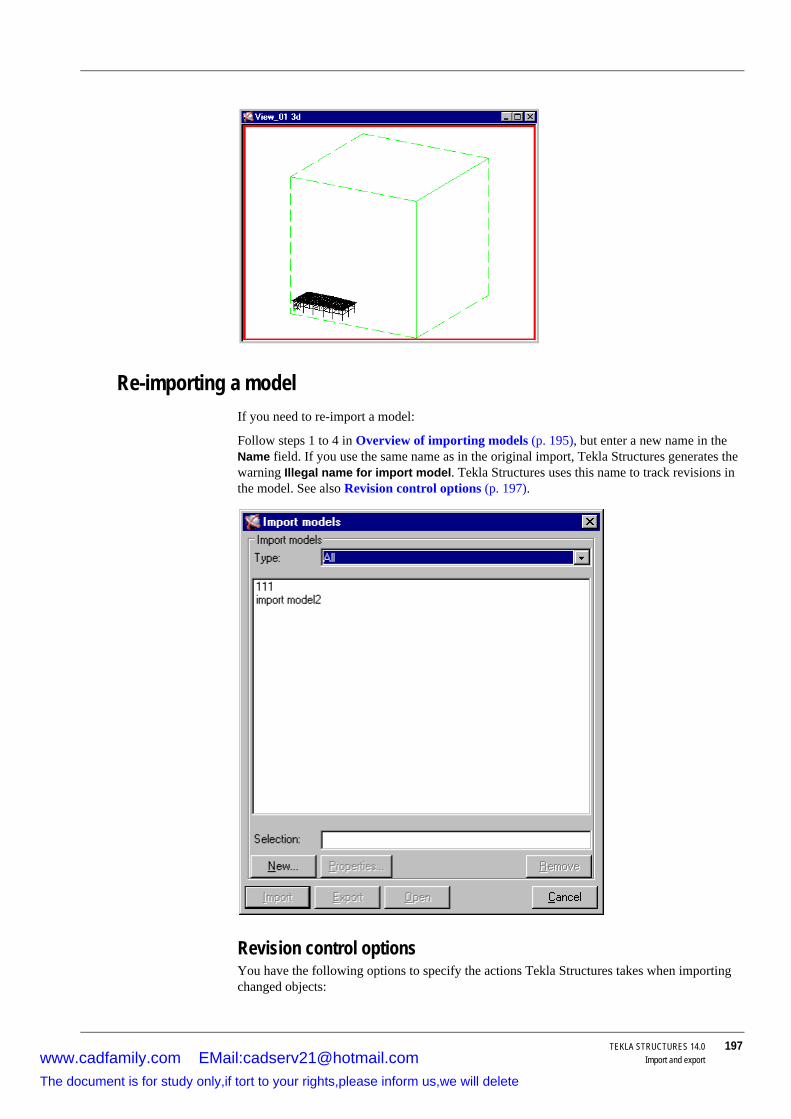
TEKLA STRUCTURES 14.0 197Import and export
Re-importing a modelIf you need to re-import a model:
Follow steps 1 to 4 in Overview of importing models (p. 195), but enter a new name in the Name field. If you use the same name as in the original import, Tekla Structures generates the warning Illegal name for import model. Tekla Structures uses this name to track revisions in the model. See also Revision control options (p. 197).
Revision control optionsYou have the following options to specify the actions Tekla Structures takes when importing changed objects:
www.cadfamily.com EMail:[email protected] document is for study only,if tort to your rights,please inform us,we will delete

198 TEKLA STRUCTURES 14.0Import and export
• The left-hand column, Previous plan, lists the state of objects in your model, compared with the state of objects in the file to be imported. They can be New, Modified, Deleted, or Same.
• Tekla Structures compares the state of objects being imported with those in your model. They can be Not in model, Different, or Same.
• Use the list boxes in the rows under Not in model, Different, or Same to specify the actions to take when importing changed objects. The options are No action, Copy, Modify, or Delete.
You can only use Delete to delete objects that have been deleted from your model, not the imported model.
Creating reports of importSome of the import tools give you the option to create a report of the import. By default, Tekla Structures does not create reports when you import files. You specify the following information using the Report tab:
Field Description
Create report Select Yes to create a report of the imported model objects.
Display report Select Yes to display the report file in the List dialog box.
Report template Enter the path of the report template, or use the browse (...) button to locate it.
Report file name Enter the path for the report file, or use the browse (...) button to locate it.
www.cadfamily.com EMail:[email protected] document is for study only,if tort to your rights,please inform us,we will delete

TEKLA STRUCTURES 14.0 199Import and export
Importing DWG/DXF filesThe DWG/DXF import tools import 3D or 2D models, in DXF or DWG. You can import the file as parts and plates, or reference lines.
To import DWG/DXF files, click File > Import > DWG/DXF....
You will need to include the following additional information about the import file:
• Create:• Reference lines displays parts in the model using their reference lines in the original
model. • Parts displays the full profile of parts in the original model, based on the profile sizes
in the Beam profile and Plate profile fields. You can only use metric profiles with this option.
• Check Use 2D import to import a two dimensional representation of the original model. This is useful when you use the reference line option. Leave Use 2D import blank to import the model in 3D.
CIS importSee Overview of importing models (p. 195) for how to import the model into Tekla Structures.
In the New import model dialog box, select CIS Analyse model import from the Type list box.
Use the following fields on the Parameters tab to specify CIS information when importing files:
Field Description
Model type Analysis or Design model. CIS version Use to select the CIS version:
• CIS/1 imports files compatible with the CIMsteel LPM4DEP1 schema declaration.
• CIS/2 imports files compatible with the CIMsteel CIS/2 (STRUCTURAL_FRAME_SCHEMA) schema declaration.
Combine members Defines whether or not the elements of a single part in the CIS file are combined to form another part in Tekla Structures. For example, if a beam in a CIS file is divided into more than one element, and you select Yes, the elements are combined to form one beam in the model. Using No means every element of the beam in the CIS file forms a single beam in the model.
Max length for combining
Only applied if you select Yes in the Combine members list box. Defines the maximum length for combining the elements in the CIS file. Elements are combined into one part only if their combined length is less than this value.
www.cadfamily.com EMail:[email protected] document is for study only,if tort to your rights,please inform us,we will delete
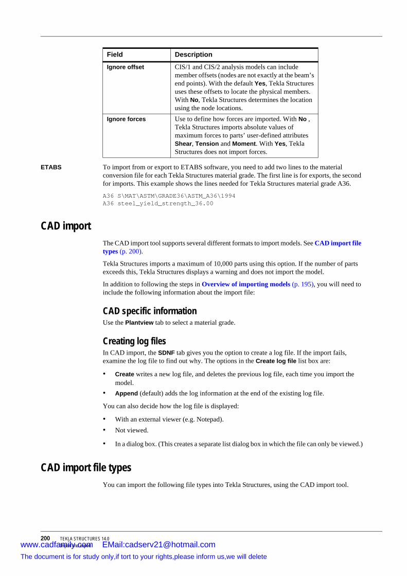
200 TEKLA STRUCTURES 14.0Import and export
ETABS To import from or export to ETABS software, you need to add two lines to the material conversion file for each Tekla Structures material grade. The first line is for exports, the second for imports. This example shows the lines needed for Tekla Structures material grade A36.
A36 S\MAT\ASTM\GRADE36\ASTM_A36\1994A36 steel_yield_strength_36.00
CAD importThe CAD import tool supports several different formats to import models. See CAD import file types (p. 200).
Tekla Structures imports a maximum of 10,000 parts using this option. If the number of parts exceeds this, Tekla Structures displays a warning and does not import the model.
In addition to following the steps in Overview of importing models (p. 195), you will need to include the following information about the import file:
CAD specific informationUse the Plantview tab to select a material grade.
Creating log filesIn CAD import, the SDNF tab gives you the option to create a log file. If the import fails, examine the log file to find out why. The options in the Create log file list box are:
• Create writes a new log file, and deletes the previous log file, each time you import the model.
• Append (default) adds the log information at the end of the existing log file.
You can also decide how the log file is displayed:
• With an external viewer (e.g. Notepad).• Not viewed.
• In a dialog box. (This creates a separate list dialog box in which the file can only be viewed.)
CAD import file typesYou can import the following file types into Tekla Structures, using the CAD import tool.
Ignore offset CIS/1 and CIS/2 analysis models can include member offsets (nodes are not exactly at the beam’s end points). With the default Yes, Tekla Structures uses these offsets to locate the physical members. With No, Tekla Structures determines the location using the node locations.
Ignore forces Use to define how forces are imported. With No , Tekla Structures imports absolute values of maximum forces to parts’ user-defined attributes Shear, Tension and Moment. With Yes, Tekla Structures does not import forces.
Field Description
www.cadfamily.com EMail:[email protected] document is for study only,if tort to your rights,please inform us,we will delete

TEKLA STRUCTURES 14.0 201Import and export
SDNF specific optionsThe SDNF tab contains the following options for SDNF imports:
Option Imports from
SDNF
Steel Detailing Neutral File
Several different CAD systems. See SDNF specific options (p. 201).
Calma Calma plant design systemHLI
High Level Interface
IEZ AG Speedikon software
Plantview Plantview design systemSDNF (PDMS)
Plant Design Management System
Cadcentre 3D plant design software
XML ArchiCAD modeling system
Field Description
Part Pos_No Enter a prefix and a start position number. Relates to Position number type below.
Apply cuts and fittings Yes (default) applies cuts and fittings in the import.
Consider offsets Use No (default) to position part creation points at part end points; Yes creates offsets.
SDNF log files Creates the log file SDNF_import.log in the current model folder. See also Creating log files (p. 200).
Position number type The SDNF file contains identifiers, which can be included in a part’s user-defined attributes, or as position numbers. You have the following options:
• Part positionThe identifier becomes the part’s posi-tion number. Do not use the Part Pos_No fields with this option.
• Universal IDThe identifier becomes a user-defined attribute for the part.
To make user-defined attributes visible, you need to add them to the objects.inp file. For more information on defining attributes in objects.inp, see Adding properties (p. 98).
www.cadfamily.com EMail:[email protected] document is for study only,if tort to your rights,please inform us,we will delete

202 TEKLA STRUCTURES 14.0Import and export
FEM importThe FEM (Finite Element Method) import tool supports several formats and provides several options for importing models. See Overview of importing models (p. 195) for how to import the model into Tekla Structures.
In the New import model dialog box, select FEM Import from the Type list box.
FEM specific informationThe FEM import formats are listed in the table below. You will need to include the following information for FEM imports:
• Use Part to enter the part position and start number for the model import.• Use Assembly to enter the assembly position and start number for the model import.
• To combine several elements in the FEM model into one part in Tekla Structures, set Combine members to Yes. For example, if a beam in an FEM model consists of more than one element, Tekla Structures combines the elements to form one beam in the Tekla Structures model. With the option NoTekla Structures creates a beam for each element in the FEM model.
• Use Maximum length to define the maximum length for combining parts. Tekla Structures combines elements into one part only if their combined length is less than the value you enter here.
FEM import file typesUse the following table to select the type of file to import:
If you want to import information, which Tekla Structures parts do not have, you can use the SDNF extension line in the SDNF file to be imported, and the REVISION_NUMBER user-defined attribute in Tekla Structures.
File typeUse to import models created in More information
DSTV
(Deutsche Stahlbau-Verband)
DSTV format DSTV files (p. 203)
Yield stress in FEM import (p. 205)
SACS SACS modeling and anal-ysis software.
Yield stress in FEM import (p. 205)
S-Frame S-Frame modeling and analysis software.
S-Frame import (p. 216)
Monorail Monorail systemStaad
(Structural Analysis And Design)
STAAD modeling and analysis system
STAAD files (p. 204)
Stan 3d Stan 3d analysis software Stan 3d files (p. 204)Bus BUS 2.5 analysis soft-
wareBus import (p. 205)
www.cadfamily.com EMail:[email protected] document is for study only,if tort to your rights,please inform us,we will delete

TEKLA STRUCTURES 14.0 203Import and export
DSTV filesThis FEM import tool imports models in the DSTV format. See basic information on FEM import (p. 202).
Fill in the following information if you have selected the DSTV import type on the Parameters tab:
• On the DSTV tab, select the DSTV version to import. • If the DSTV file to be imported contains a static and/or a CAD model, you can choose
which one to import:
Answering Yes to Import static elements imports the static model.
Answering Yes to Import other elements imports the CAD model. For more information, see Model dump import (p. 206).
About DSTVThere are three different sub-model types in DSTV:
• Static models contain general data (profiles, materials, grid lines) and static data (model, restraints, results).
• CAD models contain general data (profiles, materials, grid lines) and CAD data (elements, eccentricity).
• NC3D model contains general data (profiles, materials, grid lines), CAD data (elements, eccentricity), and construction data (holes, chamfers).
Sub-models contain four different data levels:
Only the options relevant to the selected type have any effect on the imported model.
Static data
General data
CAD data
Construction data
NC 3D model
www.cadfamily.com EMail:[email protected] document is for study only,if tort to your rights,please inform us,we will delete
204 TEKLA STRUCTURES 14.0Import and export
Different programs produce different DSTV files. For example, the DSTV file produced by RSTAB static software only contains a static model.
Tekla Structures exports either the static model (CROSS_SECTION), or the CAD model (MEMBER_LOCATION).
STAAD filesThis FEM import tool imports steel structures from the STAAD modeling and analysis system. See basic information on FEM import (p. 202).
Fill in the following information if you have selected the Staad import type on the Parameters tab:
• On the Staad tab, enter a material grade, or use the browse (...) button to locate a grade.
Tekla Structures supports the following STAAD table type specifications:
• ST (single section from the standard built-in tables) • ST PIPE (parametric)
• ST TUBE (parametric)
• RA (single angle with reverse Y_Z axes)
• D (double channel)
• LD (long leg, double angle)
• SD (short leg, double angle)
• TC (beams with top cover plates)
• BC (beams with bottom cover plate)
• TB (beams with top and bottom cover plates)
You can import the types CM and T, user-provided steel table types (UPT), and other non-standard profiles, if you have defined them in the profile conversion file. You must use the underline character in the STAAD name (e.g. UPT_1_W10X49). Tekla Structures automatically converts twin profiles in this import routine.
Stan 3d filesThis FEM import tool imports steel structures from the Stan 3d analysis software. See basic information on FEM import (p. 202).
Fill in the following information if you have selected the Stan 3d import type on the Parameters tab:
CAD model
Static model
To make a STAAD input file compatible with the Tekla Structures STAAD import, in STAAD, use the option to save the input file using the option Joint coordinate format (Single). This creates a line for each coordinate in the input file.
www.cadfamily.com EMail:[email protected] document is for study only,if tort to your rights,please inform us,we will delete

TEKLA STRUCTURES 14.0 205Import and export
• Before importing Stan 3d models, set the work plane orientation to global in Tekla Structures.
• Define the profile conversion file (prfexp_stan_3d.cnv) in the Conversion tab. You have two options for mapping profile information:
• Map section data (for example C1, FG, G1) to Tekla Structures profiles in the conversion file.
• Add full profile information in the comment field in the Stan 3d model. Then map the comment to Tekla Structures profiles in the conversion file.
• On the Parts tab, enter the part position and start number for the model import.
• On the Stan 3d tab, enter the material for all imported members in the Material field.
• Specify the scale of the import model. You can import Stan 3d without specifying the scale, as long as both the Tekla Structures model and the import are in millimeters. If the Stan 3d file is in millimeters, use a scale of 1. If the Stan 3d file is in meters, use a scale of 1000.
• The default mapping for imports is:
• Stan 3d’s Member Type to Tekla Structures’s Class.• Stan 3d’s Section Name to Tekla Structures’s user-defined attribute Prelim mark.
• Tekla Structures displays the number of parts not imported due to missing conversion information in the application window.
Bus importThis FEM import tool imports basic steel structures from the BUS 2.5 analysis software input file. See basic information on FEM import (p. 202).
On the Parameters tab, select the Bus import type, and then fill in the following information:
• On the Conversion tab, enter the name of the profile and material conversion files (prf_expbus.cnv and mat_expbus.cnv) , or use the browse (...) button to locate them.
• On the Parameters tab, enter the name of the input file (or use the browse (...) button to locate it), and the X, Y, and Z values.
• On the Bus tab, enter the position number, material, name, and class of the parts to import. Use Beams behind plane to indicate the position of girders and cantilevers. The option Yes aligns the tops of all beams at the floor level.
Yield stress in FEM importThe Default yield stress limit field is used for SACS import file.
The Default material when yield stress < limit field is used for SACS import file. Define the material to use if yield stress is less than the limit.
Tekla Structures looks at the comment field first. If it is empty or missing, Tekla Structures uses the section data.
www.cadfamily.com EMail:[email protected] document is for study only,if tort to your rights,please inform us,we will delete

206 TEKLA STRUCTURES 14.0Import and export
• Use the Default material when yield stress >= limit for SACS or DSTV import files. For SACS, this field defines the material to use if yield stress is greater than, or equal to, the limit.
• For DSTV you can enter the material grade here, if it is not contained in the import file.
Model dump importThe import model dump tool reads an ASCII file of a model dump to create a new model in Tekla Structures, including any views and drawings.
When to use If you have fatal problems with the model (e.g. cannot save the model, or cannot delete ghost parts), using a model dump is one way of saving your work.
Steps To import a model dump:
1. Open Tekla Structures and create a new model.2. Copy the model dump file (e.g. model.dmp) from an existing model folder into the new
model folder.
3. Click File > Import > Model dump.
4. Save and close the model, then reopen it to see the model.
See also Exporting a model dump (p. 237).
ASCII importThis tool imports a model in ASCII format (American Standard Code for Information Interchange). Some plant design systems export ASCII files (e.g. ModelDraft, PDS, PDMS).
Steps To import an ASCII model:
1. Create a new model in Tekla Structures. 2. Create a new 3D view.
3. Copy the ASCII file into the model folder.
4. Name the file import.asc.
5. Select File > Import > ASCII. Tekla Structures displays the main members created from the ASCII file in the model.
See also ASCII format description (p. 206)
ASCII format descriptionProfiles and polygon plates can be exported and imported using the ASCII format described in this section.
Each part is described by 8 lines. These lines are repeated for each part to be transferred. Units are always in millimeters, blanks are used as separator. Below is an example of a beam part description:
You can only import a model dump into a newly-created model. A model dump can only be imported once into one model. You can import the same model dump into several new models.
Do not use import model dumps in multi-user mode.
www.cadfamily.com EMail:[email protected] document is for study only,if tort to your rights,please inform us,we will delete

TEKLA STRUCTURES 14.0 207Import and export
The lines contain the following information:
import.asc4169 HEA300 1290.000000 8.500000 300.000000 14.000000 300.000000 14.000000A/6 BEAMS235JR S235JR0.00000016.500000 24000.000000 4855.0000006000.000000 24000.000000 4855.00000016.500000 24000.000000 5855.000000
www.cadfamily.com EMail:[email protected] document is for study only,if tort to your rights,please inform us,we will delete

208 TEKLA STRUCTURES 14.0Import and exportwww.cadfamily.com EMail:[email protected]
The document is for study only,if tort to your rights,please inform us,we will delete

TEKLA STRUCTURES 14.0 209Import and export
Line Description
Line 1 4169 HEA300 1 = ID PROFILE TYPE
• ID 4169: Unique ID (integer). • PROFILE HEA300: Profile name (string).
• TYPE 1: Profile type (integer)
The available profile types are:
• 0 = free cross section (can be used for special profiles which are not in the database)
• 1 = I profiles
• 2 = Welded hollow core profiles (HK, HQ)
• 3 = U profiles
• 4 = L profiles
• 5 = Round bars
• 6 = Round tubes
• 7 = Rectangular hollow core sections (RHS, P)
• 8 = T profiles
• 9 = Rectangular bars (FL, PL)
• 10 = Z profiles
• 11 = C profiles
• 12 = Omega profiles
• 13 = Sigma profiles
• 14 = Rail profile
• 16 = Reinforcement bars (DH)
www.cadfamily.com EMail:[email protected] document is for study only,if tort to your rights,please inform us,we will delete

210 TEKLA STRUCTURES 14.0Import and export
Line 2 The contents of line 2 depend on the part profile:
• Polygon plates:
N_POINTS COORDINATES.
N_POINTS: For profiles of type 0.
COORDINATES: Number of the corner points (integer).
The X and Y coordinates of the plate corners (floating). Rota-tion direction is clockwise. Coordinates follow the global coordinate system. Z coordinates are taken from the center line in the plate thickness direction.
Note: line 2 can be divided into several rows in the file.
• Profiles:
For profile types 1-16, the line includes the physical dimen-sions of the cross section.
HEIGHT S W1 T1 W2 T2: 290.000000 8.500000 300.000000 14.000000 300.000000 14.000000
• HEIGHT 290.000000: Height of the cross section• S 8.500000: Web thickness.
• W1 300.000000: Width of the upper flange.
• T1 14.000000: Thickness of the upper flange.
• W2 300.000000: Width of the lower flange.
• T2 14.000000: Thickness of the lower flange.
Line 3 A/6 BEAM = MARK NAME
• MARK A/6: Position mark of the part (string).• NAME BEAM: Part name (string).
Line 4 S235JR S235JR = MATERIAL
Material of the part (string).Line 5 0.000000 = ROTATION
Rotation angle (degrees) around the local x-axis of the beam.Line 6 16.500000 24000.000000 4855.000000 = X1 Y1 Z1
Coordinates of the beam starting point. Z coordinates are center-line coordinates.
Line 7 6000.000000 24000.000000 4855.000000 = X2 Y2 Z2
Coordinates of the beam end point. Z-coordinates are center-line coordinates.
Line 8 16.500000 24000.000000 5855.000000 = X3 Y3 Z3
Direction vector showing the direction of the local z-axis.
Line Description
www.cadfamily.com EMail:[email protected] document is for study only,if tort to your rights,please inform us,we will delete

TEKLA STRUCTURES 14.0 211Import and export
Attribute importUse File > Import > Attributes to import user-defined attribute values into a model from a comma- or tab-delimited text file. For example, you might import a list of manufactured or checked assemblies.
The file to import can be:
• Exported from other software• Created manually using a standard text editor
• A simple Tekla Structures report containing the part ID’s and user-defined attributes.
See About input files (p. 212) for more information on the import file.
You can import user-defined attribute values into the entire model or drawing, or into a selected area of the model.
Steps To import user-defined attributes values:
1. Copy the text file that you want to import into the model folder.2. If you only want to import user-defined attributes into a selected area of the Tekla Structures
model, select an area in the model now.
3. Click File > Import > Attributes to open the Import Attributes dialog box:
4. Click the Browse button next to the Input File field to locate the file to import.
5. Select an option in the Input scope list box. The options are:
To save an Excel spreadsheet to a tab-delimited text file, use the Save As command in Excel.
www.cadfamily.com EMail:[email protected] document is for study only,if tort to your rights,please inform us,we will delete

212 TEKLA STRUCTURES 14.0Import and export
6. Select an option in the Create log file list box. The options are:
7. Select an option in the Display log file list box. The options are:
8. Click Create to import the file.
About input filesInput files are comma or tab-delimited text files. They contain the names and values of the user-defined attributes to import into the Tekla Structures model.
In the input file, the column headings must contain the names of properties and user-defined attributes in model objects and drawings. The remaining rows contain the values of the properties and user-defined attributes. See Example input file for parts (p. 214).
Option Description
Default Tekla Structures assigns the user-defined attribute values of objects in the input file to matching objects in the model.
Entire model
Selection only
Tekla Structures only assigns the user-defined attribute values of objects in the input file to matching objects in the selected area of the model.
Only use this option to import attributes into models. Do not use for drawings.
Option Description
Create Creates a new log file named attribute_import.log in the current model folder each time you use File > Import > Attributes. This overwrites any previous attribute import log files.
Append Adds log entries to the attribute_import.log file in the current model folder each time you use File > Import > Attributes. If the log file does not exist, Tekla Structures creates it.
No Does not create a log file.
Option Description
No Does not display the log file.On dialog Displays the log file in a separate window. Click an
object ID in the log file to have Tekla Structures high-light the part in the model.
The user-defined attributes you can include in an input file are defined in the file import_macro_data_types.dat. See Data types file (p. 214) for more information.
www.cadfamily.com EMail:[email protected] document is for study only,if tort to your rights,please inform us,we will delete

TEKLA STRUCTURES 14.0 213Import and export
You must include at least one key field as a column heading. Key fields are drawing or model object properties. Tekla Structures uses these key fields to identify the model objects or drawings it will assign the user-defined attributes to.
The key fields for model objects are:
The key fields for drawings are:
Example input file for drawingsTYPE and NAME are the key fields in this input file. Tekla Structures adds a value for the user-defined attribute User field 4 to drawings with values that match those listed in the TYPE and NAME columns.
For example, a drawing with the TYPE A (assembly drawing) and NAME B.2 gets the value 4 in the User field 4.
Key field Example Action
ID 131 Tekla Structures assigns the user-defined attributes in this row in the input file to the model object that has an ID value of 131.
ASSEMBLY_POS
or
MARK
A3 Tekla Structures assigns the user-defined attributes in this row in the input file to the assembly that has an ASSEMBLY_POS value of A3
Repeat this line for each assembly you want to include.
PHASE 2 Tekla Structures assigns the user-defined attributes in this row in the input file to the assembly that has a PHASE value of 2.
You must also use ASSEMBLY_POS as a key field with this option.
Key field Example Action
TYPE NAME A D4 Tekla Structures assigns the user-defined attributes in this row in the input file to the drawing that has a TYPE value of A and a MARK value of D4
Use both key fields in the input file.
To have Tekla Structures ignore an entry in a row, replace the value with the word null. Leaving the entry blank will cause errors.
www.cadfamily.com EMail:[email protected] document is for study only,if tort to your rights,please inform us,we will delete

214 TEKLA STRUCTURES 14.0Import and export
Example input file for partsASSEMBLY_POS and PHASE are the key field in this input file. Tekla Structures adds several user-defined attributes to the assemblies with values that match those listed in the ASSEMBLY_POS and PHASE columns. For example, an assembly with the ASSEMBLY_POS (assembly number) of B5 in phase 1 gets the following user-defined attributes:
• STATUS: 3• USER_PHASE: 6
• USER_ISSUE: 3/25/2003
This input file contains repeat entries for B1. In this case, Tekla Structures writes the message Duplicate entry in input file in the log file and does not overwrite user-defined attributes that occur earlier in the file with those that occur later. For example, at the end of the attribute import, B1 will have the following user-defined attributes:
• STATUS: 7• USER_PHASE: 3
• USER_ISSUE: 3/25/2003
Data types fileThe ..\environments\*your environment*\system\import_macro_data_types.dat file is a simple text file listing the user-defined attributes that you can include in an input file.
Edit the file using any standard text editor. You can:
• Change any of the user-defined attributes that are not key fields• Add user-defined attributes as STRING, INT, FLOAT, or DATE variable types
The file contains the following columns, separated by commas or tabs:
VARIABLE_NAME, VARIABLE_TYPE, CONVERSION_FACTOR, COMMENT
attributes.txtTYPE NAME DRAWING_USERFIELD_4A B.1 3A B.2 4A C.1 1A C.2 2
attributes.txtASSEMBLY_POS PHASE STATUS USER_PHASE USER_ISSUEB1 1 7 3 3/25/2003B2 1 7 3 3/25/2003B3 1 7 3 3/25/2003B4 1 7 5 3/25/2003B5 1 3 6 3/25/2003B1 1 3 5 3/26/2003B2 2 3 4 3/26/2003
Tekla Structures uses CONVERSION_FACTOR to convert imperial values to metric. Tekla Structures only uses this value in Imperial environments. We recommend that you check the FLOAT values to avoid conversion factor errors.
www.cadfamily.com EMail:[email protected] document is for study only,if tort to your rights,please inform us,we will delete

TEKLA STRUCTURES 14.0 215Import and export
Tekla Structures treats rows starting with double forward slash characters // as comments and ignores them when reading the file. Here is a sample section of the import_macro_data_types.dat file:
Steelfab importSee Overview of importing models (p. 195) for how to import the model into Tekla Structures.
In the New import model dialog box, select SteelFab/SCIA Import from the Type list box.
Steelfab specific informationIn the SteelFab/SCIA import dialog box:
• Set Import weldings to Yes to include welds in the model.• Set Import holes to Yes to include holes in the model.
• Enter the path, file name, and file extension of the import file in the ASCII file name field. If it is blank, Tekla Structures looks in the current model folder.
Fabtrol XML importTo import the fabrication status information of parts from a Fabtrol XML file into a Tekla Structures model:
1. Click File > Import. 2. Select any of the following options FEM, CIMSteel, CAD, or Other, to open the New import
model dialog box.
Variable name
Variable type
Conversion factor
Comment
Comment
www.cadfamily.com EMail:[email protected] document is for study only,if tort to your rights,please inform us,we will delete

216 TEKLA STRUCTURES 14.0Import and export
3. Select Fabtrol XML import from the Type list box and click the Properties button to open the Fabtrol XML import (17) dialog box.
4. Click the browse button (...) to locate the file for the Input file field.
5. Click OK to import the status information.
S-Frame importImport analysis models created by the FASTSOLVE suite of programs, so you can detail them in Tekla Structures.
See Overview of importing models (p. 195) for how to import the model into Tekla Structures.
In the New import model dialog box, select Import S-Frame from the Type list box.
About S-Frame importsThe S-Frame model is used for analysis, so may not contain all the information necessary to create an accurate Tekla Structures model, particularly for positioning parts. Check the imported model carefully before you start detailing.
MicasPlus importSee Overview of importing models (p. 195) for how to import the model into Tekla Structures.
In the New import model dialog box, select Import MicasPlus from the Type list box.
MicasPlus specific informationIn the Import MicasPlus dialog box, select Front or Top from the Part rotation list box.
Eureka LPM importEureka LPM (Logical Product Model) uses the CIMsteel (Computer Integrated Manufacturing) data exchange format.
See Overview of importing models (p. 195) for how to import the model into Tekla Structures.
In the New import model dialog box, select Import Eureka LPM from the Type list box.
Overview of ELiPLAN import and exportDescription Elematic ELiPLAN is a software for resource planning, scheduling, and management for precast
concrete fabricators. Using the export and import features in Tekla Structures you can automate the data transfer between these two applications.
The data transfer consists of the following actions:
1. Exporting ELiPLAN data file from Tekla Structures2. Importing ELiPLAN data file into ELiPLAN
3. Exporting ELiPLAN status data file from Eliplan
4. Importing ELiPLAN status data file into Tekla Structures
The ELiPLAN import (2) supports incremental approach, which means that ELiPLAN is able to create, update, and delete parts in it's database. This means that precast detailers can export the most up-to-date data files whenever the Tekla Structures model has been changed.
www.cadfamily.com EMail:[email protected] document is for study only,if tort to your rights,please inform us,we will delete
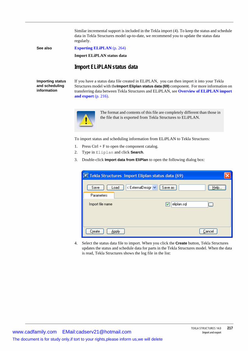
TEKLA STRUCTURES 14.0 217Import and export
Similar incremental support is included in the Tekla import (4). To keep the status and schedule data in Tekla Structures model up-to-date, we recommend you to update the status data regularly.
See also Exporting ELiPLAN (p. 264)
Import ELiPLAN status data
Import ELiPLAN status data
Importing status and scheduling information
If you have a status data file created in ELiPLAN, you can then import it into your Tekla Structures model with theImport Eliplan status data (69) component. For more information on transferring data between Tekla Structures and ELiPLAN, see Overview of ELiPLAN import and export (p. 216).
To import status and scheduling information from ELiPLAN to Tekla Structures:
1. Press Ctrl + F to open the component catalog. 2. Type in Eliplan and click Search.
3. Double-click Import data from EliPlan to open the following dialog box:
4. Select the status data file to import. When you click the Create button, Tekla Structures updates the status and schedule data for parts in the Tekla Structures model. When the data is read, Tekla Structures shows the log file in the list:
The format and contents of this file are completely different than those in the file that is exported from Tekla Structures to ELiPLAN.
www.cadfamily.com EMail:[email protected] document is for study only,if tort to your rights,please inform us,we will delete

218 TEKLA STRUCTURES 14.0Import and export
The list contains the parts whose data is updated correctly and also provides information on possible problems that may have occurred. When you select an item in the list, Tekla Structures automatically selects the corresponding part in the model.
The overall status information is shown at the end of the list.
Tekla Structures stores the actual status data to the user-defined attributes of the parts. To view the data, open the user-defined attributes from the part properties dialog box.
The ELiPLAN-specific user-defined attributes are not in the default envi-ronment of Tekla Structures. You need to modify the objects.inp to use and view them. For more information, see Configuration for ELiPLAN export.
www.cadfamily.com EMail:[email protected] document is for study only,if tort to your rights,please inform us,we will delete

TEKLA STRUCTURES 14.0 219Import and export
7.4 Exporting filesTekla Structures exports models in several formats. This section explains how to export models and drawings from Tekla Structures. Most of the export tools are available on the pull-down menu File > Export.
You can also export drawings from the drawing list, click Drawings & Reports >Drawing List....
Also, you can export your model to a web page using the command File > Publish as Web page... to make it available on the Internet, using a web browser. For more information, see Tekla WebViewer (p. 278).
Topics Exporting 3D DWG/DXF
Exporting 3D DGN
Exporting drawings
Exporting FEM
Exporting CIMsteel
Exporting CAD
Exporting MIS
Exporting ASCII
Exporting IFC
Exporting a model dump
Exporting 3D DWG/DXFYou can export models as a 3D DWG or 3D DXF file type to use in other modeling or analysis programs. By default, Tekla Structures creates the model.dwg file in the current model folder.
To create a 3D DWG/DXF export file:
1. Open a Tekla Structures model.2. Select File > Export > 3D DWG/DXF... to open the following dialog box.
www.cadfamily.com EMail:[email protected] document is for study only,if tort to your rights,please inform us,we will delete

220 TEKLA STRUCTURES 14.0Import and export
3. Modify the export options as required.
4. Accept the default file name, or use Browse... to navigate to another file.
5. Select whether to export as DWG or as DXF.
6. To export the model, click:
• Export all to export the whole model, or • Export selected to export selected parts from the model.
7. Tekla Structures creates the export file in the current model folder.
Export asFollowing options are available:
Use the Faces option to change part and bolt accuracy, and select whether or not to export cuts and inner contours.
Export as Description
Faces Exports parts as faces.Lines Exports parts as lines located in the center of profile
cross section. Used when exporting to analysis soft-ware.
Reference lines Exports parts as reference lines, drawn between the creation points. Used when exporting to analysis software.
Exporting 3D DWG or DXF files as Faces uses more memory and may take longer, but the end result is better.
If the model is large, or you have less memory to use, Export asRefer-ence lines option is faster, and the resulting file size is smaller.
www.cadfamily.com EMail:[email protected] document is for study only,if tort to your rights,please inform us,we will delete

TEKLA STRUCTURES 14.0 221Import and export
None of these options exports bolt holes. Curved beams and polybeams are exported as single, continuous beams. The number of segments in the curved beams is as defined in the Curved beam properties.
The ID of each part is exported as an attribute and written into the export file for each part.
Exporting 3D DGNThe 3D DGN export tool creates a model.dgn file in the current model folder, which you can import into other modeling systems.
Follow these steps to export a 3D DGN file:
1. Open a Tekla Structures model.2. Select the objects in the model to export.
3. Click File > Export > 3D DGN... to open the Export 3D DGN dialog box.
4. Tekla Structures creates the model.dgn file in your current model folder.
Settings You can also use the following variables to control DGN exports:
• XS_DGN_EXPORT_PART_AS (p. 317)• XS_EXPORT_DGN_COORDINATE_SCALE (p. 340)
Field Option Description
Type Normal
High Also exports chamfers in profile cross-sections.
Bolt accuracy High Exports the entire bolt assemblies, including washers.
Normal Only exports the bolt and nut.No bolts Exports no bolts.
Cuts Yes Exports cuts.Inner contours Yes Exports radiused corners in cuts.
Enter the name of the export file, or click Browse... to locate it.
Click Export all, or Export selected to export the selected parts.
www.cadfamily.com EMail:[email protected] document is for study only,if tort to your rights,please inform us,we will delete

222 TEKLA STRUCTURES 14.0Import and export
• XS_EXPORT_DGN_FILENAME (p. 340)
• XS_EXPORT_DGN_INCLUDE_CUTS (p. 340)
• XS_EXPORT_DGN_INCLUDE_INNER_CONTOUR (p. 340)
Exporting FEMThere are several options for exporting a model with the FEM (Finite Element Method) export tool.
To create a FEM export:
1. Open a Tekla Structures model.2. Click File > Export > FEM.... The FEM export dialog box appears.
3. Click the Conversion tab and enter the path to the required conversion files. For more information about conversion files, see Conversion files (p. 192).
4. Click the Parameters tab.
5. In the Output file field, accept the default, or use the browse (...) button to select another output file.
6. Select an output file type:
• DSTV
• MicroSAS
• Staad
7. Select the parts in the model to export.
8. Click Apply and then Create.
Tekla Structures creates the export file in the current model folder.
Combine segments (MicroSAS)Combine segmented members (MicroSAS) gives you the option to combine multiple parts to form one part in the exported model.
For example, if you have divided a beam into several elements and select the Yes option, Tekla Structures combines the elements so that they form one beam in the exported model. With the option No every element of the beam in the model forms individual beams.
STAADThe options on the Staad tab are only relevant to Staad file types in the FEM export.
www.cadfamily.com EMail:[email protected] document is for study only,if tort to your rights,please inform us,we will delete

TEKLA STRUCTURES 14.0 223Import and export
Parametric shapes when possible defines how Tekla Structures exports the profiles PL, P, D, PD, SPD to Staad. Yes exports the profiles as parametric shapes so that STAAD can identify them correctly. No exports all profiles as standard STAAD shapes.
Example Example of a plate PL10*200
• Exported as parametric shape (Yes): 13 PRI YD 200.000000 ZD 10.000000
• Exported as a standard shape (No):
13 TABLE ST PL10*200
If a profile is not defined on the Staad tab, Tekla Structures cannot identify it, and so does not import it.
DSTVThe options on the DSTV tab only relate to DSTV file types in FEM export.
Select a DSTV version to export:
Element reference with
Tekla Structures exports either a static model CROSS_SECTION, or a CAD model MEMBER_LOCATION.
The DSTV entities are listed below. Tekla Structures supports those marked (*). See the DSTV standard "Stahlbau - Teil 1. März 2000" for more information.
Static data:
• vertex (*)• polyline
• substructure (*)
• node (*)
• element (*)
• element_eccentricity (*)
www.cadfamily.com EMail:[email protected] document is for study only,if tort to your rights,please inform us,we will delete

224 TEKLA STRUCTURES 14.0Import and export
• raster
• boundary_condition
• elastic_support
• nodal_reaction
• element_reaction
General data:
• material (*)• cross_section (*)
CAD data:
• member (*)• member_location (*)
• construction-data
• cutout
• hole
Exporting CIMsteelYou have the following options when exporting a CIMsteel model:
• Analysis model (p. 224)• Manufacturing model (p. 226)
Analysis modelTo export a CIMsteel analysis model:
1. Open a Tekla Structures model.2. Click File > Export > CIMSteel > Analysis model.
www.cadfamily.com EMail:[email protected] document is for study only,if tort to your rights,please inform us,we will delete

TEKLA STRUCTURES 14.0 225Import and export
Use the option CIS to select the CIS (CIMsteel Intergration Standard) version.
• CIS/1 generates a file that is compatible with the CIMsteel LPM4DEP1 schema declaration.
• CIS/2 generates a file compatible with the CIMSteel CIS/2 (STRUCTURAL_FRAME_SCHEMA) schema declaration.
3. Enter the path and name for the export file in the Step file field or accept the default. If you do not enter a path, Tekla Structures creates the export file in the current model folder.
4. If required, enter the a name and organization to identify who created the export file.
5. Select one of the following standards (Flavor) to apply to the export:
• UK
• EUROPEAN
• US
6. Set units to metric or imperial.
7. Enter values for the origin of the exported model. The origin comes from the origin in Tekla Structures.
8. To split a part in the Tekla Structures model into several elements in a CIMsteel model, select Split members (Yes).
As an example, three columns are connected to a beam in a model, so that one column is in the middle and the others are at each end of the beam. With the Yes option the beam is split into two equal elements in the CIMsteel model. With the No option there will be one beam, a single linear element, and two nodes (a node at each end), in the CIMsteel model.
9. Select the parts in the model to export, then click Apply and Create.
Imperial is only available for CIS/2. CIS/1 is always exported in metric units.
www.cadfamily.com EMail:[email protected] document is for study only,if tort to your rights,please inform us,we will delete

226 TEKLA STRUCTURES 14.0Import and export
Manufacturing modelFollow these steps to export a CIS2 CIMsteel manufacturing model:
1. Open a Tekla Structures model.2. If you want to include information on drawings and NC files in the export file, you need to
• Export or print needed drawings to the model folder in dwg format. See Exporting drawings (p. 266) or Printing to file.
• Create single-part drawings, and then create NC files with the extension .nc1. See DSTV (p. 174).
3. Click File > Export > CIMSteel > Manufacturing model to export a model that contains all of the parts needed for manufacture and erection.
4. Click the Parameters tab.
5. Enter a name for the export file in the Output file field. CIS uses the file extension stp.
6. Set Linear units to metric or imperial units (only for CIS/2 format).
7. If required, enter a name for the structure in the Structure name field.
8. Enter the path to the profile conversion file. For more information, see More CIMsteel information (p. 227).
9. Enter the path to the material conversion file. For more information, see Material conversion.
With Imperial units Tekla Structures writes all of the designations for nuts, bolts, and washers in fractional inches.
www.cadfamily.com EMail:[email protected] document is for study only,if tort to your rights,please inform us,we will delete

TEKLA STRUCTURES 14.0 227Import and export
10. To include information on NC files in an export, set Include NC files to Yes and specify a path (relative to the current model folder) to the folder where the NC files are located.
11. To export globally unique ID’s instead of internal ID numbers, select Yes in the Export Globally unique ID’s list box.
12. Click the Profile standard tab to enter information about the standard.
13. Select the parts in the model to export.
14. Click Apply and then Create. Tekla Structures creates the export file in your current model folder.
More CIMsteel informationProfile conversion
This example shows part of the profile conversion file prfexp_cis.cnv:
Converted-name contains the following information, each value separated by a back slash ‘\’:
• S (fixed value)• SECT (fixed value)
• Name of the standardization organization
• Standard name of the profile shape
• Name of the standard
• Year of the standard
If the conversion file does not contain the relevant profile type, the Tekla Structures name of the profile is used. Tekla Structures also uses the Standardization organization, Standard name and Year of standard defaults on the Profile standard tab.
Material conversion
This example shows part of the material conversion file matexp_cis.cnv:
If you leave the profile and material conversion file paths empty, Tekla Structures uses the conversion files in the current profile folder for the conversion.
! US Imperial Flavor! Profile name conversion Tekla Structures -> CIS! ! If Converted-name does not exist, it will be! the same as Tekla Structures-name.
! Tekla Structures-name Converted-name
!!American Sections - Imperial
!W - Wide Flange BeamsW44X335 S\SECT\US\W44X335\ASTM_A6\1994W44X290 S\SECT\US\W44X290\ASTM_A6\1994W44X262 S\SECT\US\W44X262\ASTM_A6\1994
www.cadfamily.com EMail:[email protected] document is for study only,if tort to your rights,please inform us,we will delete

228 TEKLA STRUCTURES 14.0Import and export
Converted-name contains the following information, each item separated by the backslash character (\):
• S (fixed value)• MAT (fixed value)
• Name of the standards organization
• Standard name of the material
• Name of the standard
• Year of the standard
Converted-name contains the following information about bolts, nuts, and washers, separated by two colon characters (::):
• Name of the standards organization• Name of the standard
• Year of the standard
• Standard name of the bolt, washer, or nut
Tekla Structures names for bolts, washers, and nuts are constructed from their fastener standard, fastener type and size.
If the conversion file does not contain an equivalent profile name, Tekla Structures uses the name of the material.
Tekla Structures takes the following default values from the Material standard and Bolt standard tabs for materials, bolts, nuts and washers:
! US Imperial Flavor! Material name conversion Tekla Structures -> CIS! ! If Converted-name does not exist, it will be ! the same as Tekla Structures-name.
! Tekla Structures-name Converted-name
# Carbon Structural Steel (ASTM_A36\1994)GRADE32 S\MAT\US\GRADE32\ASTM_A36-94\1994GRADE36 S\MAT\US\GRADE36\ASTM_A36-94\1994#High Strength Carbon Manganese Steel (ASTM_A529\1994GRADE42 S\MAT\US\GRADE42\ASTM_A529-94A\1994)
Field Description
Standardization organiza-tion
The organization that published the standard.
If this field is blank, Tekla Structures places an empty entry ("") in CIS/2 files.
Name of standard The name or number of the standard.
If this field is blank, Tekla Structures places an empty entry ("") in CIS/2 files.
Year of standard The year the standard was published.
If the field is left blank, Tekla Structures uses 1999 as the default value.
www.cadfamily.com EMail:[email protected] document is for study only,if tort to your rights,please inform us,we will delete

TEKLA STRUCTURES 14.0 229Import and export
Exporting CADYou can export a CAD model in several formats. To export a CAD model:
1. Open a Tekla Structures model.2. Click File > Export > CAD... to open the CAD export dialog box.
3. Click the Conversion tab and enter path to the required conversion files. For more information about conversion files, see Conversion files (p. 192).
4. Click the Parameters tab.
5. In the Output file field, accept the default, use the browse (...) button to select another output file.
6. Select one of the output formats in the Type list box:
Format Description
PML PML exports files in Intergraph’s Parametric Modeling Language format. The PML export can be used with several Intergraph systems.
HLI HLI (High Level Interface) option is used for exporting data to IEZ AG’s Speedikon software.
SCIA SCIA is used for SteelFab interface.Calma Calma option is used for exporting data to the Calma plant
design system.SDNF SDNF (Steel Detailing Neutral File) option is used to
export models for use in several different CAD systems.PDMS PDMS (Plant Design Management System) option is used
to export models for use with the Cadcentre’s 3d plant design software. For more information, see PDMS (p. 232).
SDNF (PDMS) SDNF (PDMS) is used for exporting information to PDMS via SDNF link. Tekla Structures writes the information of finish field in the member class attribute, whereas in SDNF export it omits the class information.
XML XML is used for exporting information to ArchiCAD modeling system. There are some limitations in the export:
• Conversion files are not used. • Holes, bolts and welds are not exported.
www.cadfamily.com EMail:[email protected] document is for study only,if tort to your rights,please inform us,we will delete

230 TEKLA STRUCTURES 14.0Import and export
7. Use the Origin X, Y, Z fields to specify the origin of the exported model.
8. Select the parts in the model to export.
9. Click Apply and then Create.
Tekla Structures then creates the export file in your current model folder.
PMLFor PML output format, use the following options on the PML tab.
• Select the units for the export model.• Export cut parts controls whether cuts are included in the export. Select Yes to export part
cuts.
The following variables control PML export:
• PML_ASSEMBLY_MARKS_IN_USE (p. 370)• PML_CARDINAL_POINT_NOT_IN_USE (p. 371)
SDNFFor SDNF, SDNF(PDMS), or PDMS output formats, use the following options on the SDNF tab:
When you export models from Tekla Structures into an other software using PML, enter the Tekla Structures profile names in the conversion file. This makes the other software consider parts as beams and columns (not as plates), and reduces the export file size.
www.cadfamily.com EMail:[email protected] document is for study only,if tort to your rights,please inform us,we will delete

TEKLA STRUCTURES 14.0 231Import and export
Field Description
SDNF version number Select the SDNF version to be used in the export.Apply cuts and fittings Select Yes (default) applies cuts and fittings in the export.Position number type The SDNF file contains identifiers, which can be included
in a part’s user-defined attributes, or as position numbers. You have the following options:
• Part positionThe identifier becomes the part’s position number. Do not use the Part Pos_No fields with this option.
• Assembly position
The identifier becomes the assembly’s position number.
• Universal ID
The identifier becomes a user-defined attribute for the part.
To make user-defined attributes visible, you need to add them to the objects.inp file. For more information on defining attributes in objects.inp, see Adding proper-ties (p. 98).
www.cadfamily.com EMail:[email protected] document is for study only,if tort to your rights,please inform us,we will delete

232 TEKLA STRUCTURES 14.0Import and export
XMLFor XML output formats, use the following options on the XML tab:
• Use Units to specify unit conversions. For example, for a Tekla Structures model created using millimeters, select IN to convert all part dimensions to inches in the output file.
• XML structure ID is a unique identification number for the exported model. You must always enter an identification number. Tekla Structures uses this value to identify the model if you re-export it.
PDMSTekla Structures uses some of the information you enter on the SDNF tab. It supports two different PDMS export formats, EXTRUSION and NOZZLE.
Tekla Structures decides which export format to use by searching for the Tekla Structures profile name in the profile conversion file (by default, prfexp_pdms.cnv). If the profile is not there, Tekla Structures exports the part in both EXTRUSION and NOZZLE formats.
Consider offsets To ignore the offset records during export, select No, and to take them into account, select Yes.
This setting does not affect the actual start and end point information, only the offset. Tekla Structures writes the start and end points based on the actual solid, not on the reference line.
PDMS phase offset PDMS phase offset defines phase offset for exported parts. For example, if the first phase in Tekla Structures model is 1 and you enter 10 for phase offset, the Tekla Structures parts in another software get the phase 11 and up.
Engineering Firm Enter the name of the engineering firm.Client Enter the name of the client.Structure ID Enter a unique identification number for the exported
model.Project ID Enter a unique identification number for the exported
project.Revision Number Enter a revision number (optional). Tekla Structures takes
the revision number from the user-defined attributes (REVISION_NUMBER) of the model. If this field is blank, Tekla Structures uses a revision number from the CAD export dialog box (Revision Number).
Issue Code Tekla Structures writes the issue code in the header section of the output file. For PDMS, this value should always be "Tekla Structures".
Design Code Define the design code to be used in structural design. For more information, see Design codes and methods.
When you add a profile to the NOZZLE catalog, you must also add it to the profile conversion file.
Field Description
www.cadfamily.com EMail:[email protected] document is for study only,if tort to your rights,please inform us,we will delete

TEKLA STRUCTURES 14.0 233Import and export
Using EXTRUSION elements
EXTRUSION transfers data from Tekla Structures to PDMS using EXTRUSION elements. Tekla Structures describes profiles in the export file using the vertices of the profiles. So you can also export contour plates and folded plates. Tekla Structures exports profiles as solids, which may not be suitable for some profile types (e.g. tubes).
Loading a NOZZLE catalog
You can also transfer data from Tekla Structures to PDMS by loading a NOZZLE catalog into a PDMS project. The NOZZLE catalog is contained in the file load_nozz_cata.mac, located in the European profile folder. This file describes the profiles you can export to PDMS systems. It also enables Tekla Structures to use NOZZLE elements. This format creates exact profiles (even for tube profiles), and a smaller export file than the EXTRUSION option. You can edit the NOZZLE catalog with a text editor to add profiles to it.
Exporting MISUse the MIS (Manufacturing Information System) tool to create list files. You can create them from selected parts, or from all the parts in the model. The MIS command creates the following file types: DSTV, KISS, EJE, EPC, or Steel 2000.
To create an MIS list file:
1. Open the Tekla Structures model to export.2. Click File > Export > MIS... to display the MIS dialog box.
3. In the MIS type list box, select the file type. See MIS types (p. 233).
4. In the MIS list file field, enter the name of the list file, including the file extension. You need to use specific file extensions for some file types. See MIS list file (p. 234) for a list of file extensions.
5. Click Create all or Create selected. Tekla Structures creates the MIS file in the current model folder.
MIS typesThe file types you can use for MIS output are:
• DSTVThe file only contains the MIS information for the DSTV model.
• Fabtrol/KISS
Gives you the following additional options:
• Customer name
www.cadfamily.com EMail:[email protected] document is for study only,if tort to your rights,please inform us,we will delete

234 TEKLA STRUCTURES 14.0Import and export
• Full material list. Check this box to add labor-related information to the list (holes, welds, cambers, preliminary marks, etc.).
• EJEUS Imperial version only.
• EPC
The EPC (Estimating and Production Control) module of SDS/2 requires multinumbering to be active.
• Steel 2000
MIS list fileUse the following MIS list file extensions, according to which file type you are creating:
Exporting ASCIITo export an ASCII file of a model:
1. Open the Tekla Structures model you want to export.2. Select the parts of the model you want to export.
3. Click File > Export > ASCII. Tekla Structures creates the model.asc file in the current model folder.
See also ASCII format description (p. 206)
Exporting IFCYou can export the basic parts of a Tekla Structures model into IFC2X, IFC2X2, IFC2X3 and IFC2X3_mapping schema edition files.
To define as which IFC entities the model objects are exported, use the user-defined attributes:
1. Double-click the part to open the part properties dialog box, and click User-defined attributes... button.
2. On the IFC export tab, define the following properties:
Structural Material Manager internally stores all dimensions in sixteenths. Its External Data Interface writes all dimensions, such as widths, lengths, etc, except for Beam and Channel descriptions, in sixteenths of an inch.
As an example the length 12'-8 7/8 is equivalent to 2446 sixteenths, which is calculated as (feet x 192) + (inches x 16) + sixteenths.
Type File extension
DSTV xsr
Fabtrol/KISS kss
EJE eje
EPC NoneSteel 2000 None
www.cadfamily.com EMail:[email protected] document is for study only,if tort to your rights,please inform us,we will delete

TEKLA STRUCTURES 14.0 235Import and export
IFC entity attribute set as Auto:
Property Option Description
IFC entity Auto The object is exported as default entity.
See a list of default settings below.
None The object is not exported.IfcBeam Supported IFC entities.IfcColumn
IfcWall
IfcWallStandardCase
IfcBuildingElement-Part
IfcSlab
IfcPlate
IfcFooting
IfcPile
IfcRailing
IfcBuildingElement-Proxy
IfcMember
IFC export type BREP Brep presentation is used for all objects.
AUTO Constructive solid geometry is used when possible, and brep presentation is used otherwise.
IFC site name Enter the site, building and building storey name.
With these fields you can divide the parts to different sites, buildings and building storeys.
If you leave the fields empty, the site, building, and building storey name remain undefined in the IFC file.
IFC building name
IFC building storey name
Tekla Structures object IFC entity exported
Beam IfcBeamTwin profile 2x IfcBeamColumn IfcColumn
www.cadfamily.com EMail:[email protected] document is for study only,if tort to your rights,please inform us,we will delete

236 TEKLA STRUCTURES 14.0Import and export
To export a Tekla Structures model into an IFC file:
1. Select the model objects to export.2. Click File > Export > IFC...
3. Select the Schema edition, the options are IFC2X, IFC2X2, IFC2X3 and IFC2X3_mapping.
4. Browse for the Output file location and enter the file name. The file extension for the output file is .ifc.
The length of the file path is limited to 256 characters.
5. Select whether to export parametrized profiles or not: Select Yes or No in the Parameterized profile list box.
6. Select the export type, the options are AUTO and BREP.
Defining the color of the exported objects
The color of the exported objects is defined according to the class definition, in the following manner:
Slab IfcSlabConcrete Panel IfcWallStandardCasePad footing IfcFootingStrip footing IfcFootingContour plate IfcPlate
Number all parts before exporting when you have selected the IFC2X3_mapping schema edition.
Tekla Structures object IFC entity exported
Class definition Color
1 Grey2 Red
www.cadfamily.com EMail:[email protected] document is for study only,if tort to your rights,please inform us,we will delete

TEKLA STRUCTURES 14.0 237Import and export
Limitations
Exporting a model dumpA model dump creates an ASCII file of a model that you can use in other models.
To export a model dump file:
1. Open the Tekla Structures model to export.2. Click File > Export > Model dump.
Tekla Structures creates the model.dmp file in the current model folder.
3 Green4 Dark blue5 Cyan6 Yellow7 Dark magenta8 Dark grey9 Dark red10 Dark green11 Dark cyan12 Magenta13 Orange14 Blue
Class definition Color
The following model parts are not supported in the export:
• Bolts, nuts and washers• Welds
• Reinforcing bars
• Surface treatments
• Grids
www.cadfamily.com EMail:[email protected] document is for study only,if tort to your rights,please inform us,we will delete

238 TEKLA STRUCTURES 14.0Import and export
See also Model dump import (p. 206).
Exporting BVBSDescription This component exports the geometry of reinforcements into BVBS (Bundesvereinigung
Bausoftware) format. The result is a text file in ASCII format. The supported versions of the BVBS format are:
• 1.0 year 1995• 2.0 year 2000
The component is able to export bent reinforcing bars, reinforcing bar groups and polygonal or rectangle not-bent meshes. The export of the hooks is also supported.
Limitations Each point of unbent reinforcement must lie on the same plane (BF3D export is not supported).
Example 1 Exporting reinforcements with standard bending radius:
The model dump file contains the entire model, including views and drawings.
www.cadfamily.com EMail:[email protected] document is for study only,if tort to your rights,please inform us,we will delete

TEKLA STRUCTURES 14.0 239Import and export
BF2D@Hj57@r0@ia@p1@l922@[email protected]@d12@gA500HW@s30@v@Gl375@w90@l547@w0@C85@
Example 2 Exporting reinforcements with non-standard bending radius:
BF2D@Hj57@r0@ia@p1@l831@[email protected]@d12@gA500HW@s30@v@Gl163@w0@r200@w90@l335@w0@C84@
See also Exporting reinforcement to BVBS format (p. 240)
www.cadfamily.com EMail:[email protected] document is for study only,if tort to your rights,please inform us,we will delete

240 TEKLA STRUCTURES 14.0Import and export
Export rebar BVBS (78) dialog box (p. 240)
BVBS (78) specification (p. 242)
Exporting reinforcement to BVBS formatTo export the geometry of the selected reinforcement to the BVBS format, follow the steps below.
Preconditions If you create a new reinforcement in an actual model, you need to close and re-open the export dialog box.
Usage 1. Select the reinforcing bars to export. 2. Click Ctrl + F to open the component catalog. Type in BVBS and click Search. Double-
click Export rebar BVBS (78) to open the component dialog box.3. Set the following options in the Export rebar BVBS (78) dialog box:
a Set Selection to Selected rebars only.b Set Standard bending radius to Use Tekla standards.c Set Draw rebars to Yes to see the exported geometry in the model after exporting.
4. Click Create.5. Check the exported geometry. 6. Find the name of the exported file in the component output window.7. Check the created file in the current model folder.
Result Using this component creates one output file. The output file is created in the current model folder. The file name depends on the settings in the dialog box and it is shown in the console output window (see the picture). The existing files are rewritten. To check the exported geometry, set Draw rebars to Yes.
See also Export rebar BVBS (78) dialog box (p. 240)
BVBS (78) specification (p. 242)
Export rebar BVBS (78) dialog boxThis section describes the fields in the Export rebar BVBS (78) dialog box.
www.cadfamily.com EMail:[email protected] document is for study only,if tort to your rights,please inform us,we will delete

TEKLA STRUCTURES 14.0 241Import and export
Configuration
Field Description
File name Specify the name of the output file. The default file name is Project Number.
Ext file name Specify the extension of the output file. The default file extension is txt.
Version Specify the version of the BVBS format. The supported versions of BVBS are:
1.0 year 1995
2.0 year 2000Selection Define which reinforcements will be exported.
• All rebars in the model no preselected parts are required, all reinforcements from the current model are exported.
• Selected rebars only only the selected reinforce-ments are exported.
• All rebars of selected concrete elements only reinforcements that belong to the selected concrete parts are exported.
2D rebars Export single reinforcing bars and groups consisting of straight bars.
3D rebars Export bent reinforcing bars. Not supported at the moment.
Spiral rebars Export spiral reinforcements. Not supported at the moment.
Not bent meshes Export unbent meshes. Polygonal and rectangle meshes are supported.
Bent meshes Export bent meshes. Not supported at the moment. Standard bending radius Specify the value of the standard bending radius.
• Use Tekla standards: Each material and diameter has its own initial bending radius in Tekla Struc-tures. These values are used for each reinforcing bar group from the file \environ-ments\europe\profil\rebar_database.inp (Column “Min bend rad”). These values are used for the standard bending radius.
• Use radius coef: the standard bending radius is the bending radius of the exported reinforcing bars multiplied with Radius coef.
• Use rebar radius: the bending radius of exported reinforcing bars is used as the standard bending radius.
Radius coef Define the number used for the computation of the stan-dard bending radius. Entire number is required. Used only if Standard bending radius is set to Radius coef.
www.cadfamily.com EMail:[email protected] document is for study only,if tort to your rights,please inform us,we will delete

242 TEKLA STRUCTURES 14.0Import and export
BVBS (78) specificationEach exported reinforcing bar or group of the same reinforcing bars has one row in the exported file. One row consists of a HEADER block, a GEOMETRY block and a CHECKSUM block.
Example BF2D@Hj57@r0@ia@p1@l5950@[email protected]@d12@gA500HW@s30@v@Gl5950@w0@C84@
Header block starts with the letter H.
• j – Project number • r – Plan number – not used, exported as 0
• i – Plan index – not used, exported as “a”
• p – Position – index of the output file row is exported
• l – Total length of reinforcement
• n – Number of reinforcements
• e – Weight of one rod
• d – Reinforcement diameter
• g – Material
• s – Standard bending radius (see below)
• v – Author – not used
Geometry block starts with the letter G.
• l – particular length • w – bending angle
• r – bending radius (relates to the standard bending radius, see below)
CheckSum block starts with the letter C.
• see the BVBS specification
Measuring Measuring of the length is done according to the BVBS specification. Calculation of lengths also depends on the bending angle. Lengths L1 and L2 are exported.
Draw rebars Draw the exported geometry in the model. It is repre-sented by the lines created inside reinforcements (straight bars and meshes) or on the side of reinforce-ments (bent bars).
In case of 180° hooks, the hook line is inside the main line.
Ignored classes List of classes. Reinforcements with classes in this list will not be exported. E. g. “5 7 17”.
Field Description
www.cadfamily.com EMail:[email protected] document is for study only,if tort to your rights,please inform us,we will delete

TEKLA STRUCTURES 14.0 243Import and export
Standard bending radius
The bending radius affects the export of the reinforcements. If the bending radius is the same for the entire reinforcing bar and this bending radius is set by dialog box field Standard bending radius (is also written in exported HEADER block), these bending radiuses are not exported in the GEOMETRY block. Otherwise the bending radiuses are exported for each bending. The value of the bending radius can be set in fields Standard bending radius and Radius coef in the dialog box.
Exporting UnitechnikDescription This component exports the 3D geometry of the cast units into Unitechnik format. The result is
a text file in ASCII format. Supported versions of the Unitechnik format are:
• 6.0.0 14.6.2005 • 5.2b 11.9.2000
• 5.0c 30.10.1997
This component is able to export cast units consisting of concrete, steel and surface materials. Exporting of not-bent reinforcing bars, reinforcing bar groups and meshes with hooks is also supported. This macrocomponent also supports exporting braced girders and double walls.
Example 1 Exported cast unit:
www.cadfamily.com EMail:[email protected] document is for study only,if tort to your rights,please inform us,we will delete
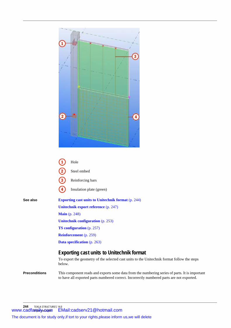
244 TEKLA STRUCTURES 14.0Import and export
See also Exporting cast units to Unitechnik format (p. 244)
Unitechnik export reference (p. 247)
Main (p. 248)
Unitechnik configuration (p. 253)
TS configuration (p. 257)
Reinforcement (p. 259)
Data specification (p. 263)
Exporting cast units to Unitechnik formatTo export the geometry of the selected cast units to the Unitechnik format follow the steps below.
Preconditions This component reads and exports some data from the numbering series of parts. It is important to have all exported parts numbered correct. Incorrectly numbered parts are not exported.
Hole
Steel embed
Reinforcing bars
Insulation plate (green)
www.cadfamily.com EMail:[email protected] document is for study only,if tort to your rights,please inform us,we will delete

TEKLA STRUCTURES 14.0 245Import and export
Usage 1. Update numbering.2. Select one object of a cast unit. 3. Click Ctrl + F to open the component catalog. Type in Unitechnik and click Search.
Double-click the Export unitechnik (79) to open the Export unitechnik (79) dialog box.4. On the Main tab, set the Create from to Selected cast units.5. On the TS configuration tab, set the following fields:
a Draw profs to Yes to see exported geometry in the model after creating the component.
b Insulation classes to 3. Green object with class 3 will be considered as insulation plate.
c Embeds to Selected + steel (orange steel objects will be considered as embeds)
6. On the Reinforcement tab, set the following fields:a Single rebars export to Yes to export reinforcing bars in the top concrete panel. b Mesh export to Yesto export reinforcing bars in the bottom concrete panel.
7. Click Create.8. Check the exported geometry. 9. Search the name of the exported file in the component output window.10. Check the created file in the current model folder.
Result This component creates one or several output files. Number of created output files depends on the option selected in the Create from list and the total number of selected parts, cast units or assemblies.
The parts you need to select depend on the selected option in the Create from list.
www.cadfamily.com EMail:[email protected] document is for study only,if tort to your rights,please inform us,we will delete

246 TEKLA STRUCTURES 14.0Import and export
If the scanning direction is wrong, use the Rotation and Extra rotation fields.
Wrong scanning plane (from the right side to the left side):
Correct scanning plane ( from back to front side):
www.cadfamily.com EMail:[email protected] document is for study only,if tort to your rights,please inform us,we will delete

TEKLA STRUCTURES 14.0 247Import and export
See also Exporting Unitechnik (p. 243)
Unitechnik export reference (p. 247)
Data specification (p. 263)
Unitechnik export referenceObject geometry scanning
To obtain the geometry of all parts in a cast unit this component uses scanning layers. The number of the scanning layers depends on the selected Scan position (p. 258). Each object of the cast unit is scanned in one direction, which can be set with Rotation (p. 248) and Extra rotation (p. 250) properties.
Real scanned geometry can be shown in the model after you have used the component with Draw profiles (p. 257) property.
Insulation All parts considered as insulation (see Insulation classes (p. 259)) are exported in the MOUNTPART block.
Embeds All embeds (see Embeds (p. 259) and Embed classes) are exported in the MOUNTPART block. Other properties that affect the export of embeds are Export assemblies (p. 252) and Export assemblies outside (p. 252). If the embeds block consists of several parts, it is useful to weld all embeds into one block and then connect the created block with concrete part to a cast unit. Subassemblies are also supported.
Reinforcement This component can export single and groups of straight reinforcing bars, rectangular or polygonal meshes. The export of the bent reinforcing bars and bent meshes is ignored. The reinforcing bar group, rectangular or polygonal mesh is divided into several single reinforcing bars. All reinforcing bars are exported in the RODSTOCK block. The exported geometry can be shown with Draw profiles. This property shows the inside lines of the exported reinforcing bars. Hooks are also supported. If Export type is set to Fabrication of welded rebars, the single reinforcing bar is exported in one STEELMAT block, all reinforcing bars of one group are
www.cadfamily.com EMail:[email protected] document is for study only,if tort to your rights,please inform us,we will delete

248 TEKLA STRUCTURES 14.0Import and export
exported together in one STEELMAT block, all reinforcing bars of one mesh are also exported together in one STEELMAT block.
Braced girders The class of reinforcements, steel rods or profiles representing braced girder has to be entered in the Braced girder classes (p. 260) field. For example 15 17 5 means that parts with class 15, 17, or 5 are consider as braced girders. If the Braced girder export and Braced girder classes fields are not set, the braced girders will be exported incorrectly as reinforcement or embeds.
Double walls Set the user-defined attribute Product type (UT product type) of the first panel to Double wall (1st stage). Set the other panel to Double wall (2nd stage). Double wall panels are exported separately in UNITECHNIK.
MainThis describes the fields on the Main tab of the Export unitechnik (79) component.
Create from This option defines the parts or cast-units that are exported.
• All parts: preselected parts are not required, all cast units from the current model are exported. Each cast unit has one output file.
• Selected cast units: exports only cast units that have one or more parts selected in the model. Each cast unit has one output file.
• Selected parts (specially): exports only the selected concrete parts (also embeds and insulation parts belonging to the selected part). Each part has one output file.
• Selected parts (cast united): selected parts belonging to one cast unit are grouped and exported together in one output file.
• Selected assemblies: all selected assemblies are exported. One assembly equals one cast unit and has one output file. Selection of subassemblies is also allowed.
Rotation This option defines the scanning direction. The scanning direction depends on the plane of the cast unit main part. A floor panel is scanned from bottom to top side. Awall panel and a column are scanned from one side to the other side. The position and direction of a basic shape of the exported cast unit depends on the rotation.
www.cadfamily.com EMail:[email protected] document is for study only,if tort to your rights,please inform us,we will delete

TEKLA STRUCTURES 14.0 249Import and export
Option Description Example
No Floor: Bottom to top
Wall: Front to rear side
Column: Side to side
180 Floor: Top to bottom
Wall: Rear to front side
Column: From one side to the opposite side
+90 around X Floor: Left to right side
Wall: Top to bottom
Column: Side to side
-90 around X Floor: Right to left side
Wall: Bottom to top
Column: From one side to the opposite side
www.cadfamily.com EMail:[email protected] document is for study only,if tort to your rights,please inform us,we will delete
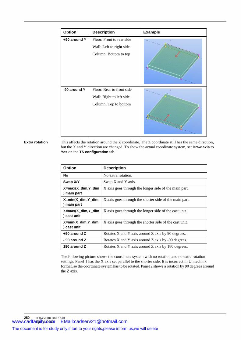
250 TEKLA STRUCTURES 14.0Import and export
Extra rotation This affects the rotation around the Z coordinate. The Z coordinate still has the same direction, but the X and Y direction are changed. To show the actual coordinate system, set Draw axis to Yes on the TS configuration tab.
The following picture shows the coordinate system with no rotation and no extra rotation settings. Panel 1 has the X axis set parallel to the shorter side. It is incorrect in Unitechnik format, so the coordinate system has to be rotated. Panel 2 shows a rotation by 90 degrees around the Z axis.
+90 around Y Floor: Front to rear side
Wall: Left to right side
Column: Bottom to top
-90 around Y Floor: Rear to front side
Wall: Right to left side
Column: Top to bottom
Option Description Example
Option Description
No No extra rotation. Swap X/Y Swap X and Y axis. X=max(X_dim,Y_dim) main part
X axis goes through the longer side of the main part.
X=min(X_dim,Y_dim) main part
X axis goes through the shorter side of the main part.
X=max(X_dim,Y_dim) cast unit
X axis goes through the longer side of the cast unit.
X=min(X_dim,Y_dim) cast unit
X axis goes through the shorter side of the cast unit.
+90 around Z Rotates X and Y axis around Z axis by 90 degrees.- 90 around Z Rotates X and Y axis around Z axis by -90 degrees.180 around Z Rotates X and Y axis around Z axis by 180 degrees.
www.cadfamily.com EMail:[email protected] document is for study only,if tort to your rights,please inform us,we will delete

TEKLA STRUCTURES 14.0 251Import and export
Special assemblies export / Special export assembly file name
These properties influence the exported geometry of the embeds. The real geometry is replaced by the geometry defined in special text files. The default name of the text file is spec_assemblies_def.txt and is primary searched in the model folder. The file name and path can be specified by the Special export assembly file name property.
Required structure of text file is:
• Name(text) Number_of_lines_defined(number) • S(representing single line) Start_coors(number number) End_coors(number number)
• S(representing single line) Start_coors(number number) End_coors(number number)
Example of the file:
The geometry of all embeds with names (from example Quicky, QuickyS, E-Doze) are replaced by geometry defined in the text file. In the following example, the part number 1 (the name is Beam) was not found in the text file so the geometry is exact. On the opposite side the part number 2 (the name is Quicky) was found, so the geometry is replaced.
www.cadfamily.com EMail:[email protected] document is for study only,if tort to your rights,please inform us,we will delete

252 TEKLA STRUCTURES 14.0Import and export
Export assemblies
Specifies export of embeds and steel blocks.
Export assemblies outside
Defines if embeds outside concrete part are exported or not.
Option Description
Exports embeds as parts. All embed welds and assembly relations are ignored. The exported geometry is a projection of the objects into the basic shape.
Welded embeds and assembly block are exported as one part.
Exports only the main part of the embed block or embed assembly.
Exports the main part of the embed block extended in the X direction to cover all the parts of the embed block.
www.cadfamily.com EMail:[email protected] document is for study only,if tort to your rights,please inform us,we will delete
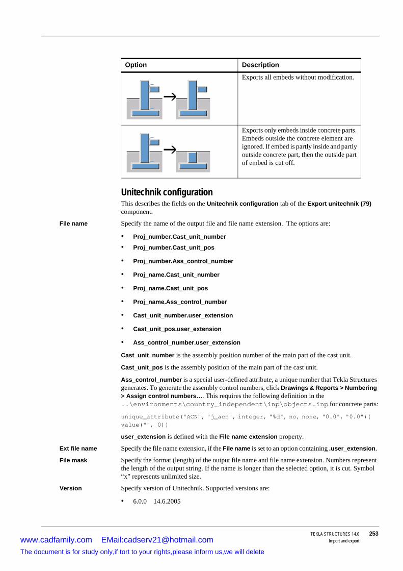
TEKLA STRUCTURES 14.0 253Import and export
Unitechnik configurationThis describes the fields on the Unitechnik configuration tab of the Export unitechnik (79) component.
File name Specify the name of the output file and file name extension. The options are:
• Proj_number.Cast_unit_number
• Proj_number.Cast_unit_pos
• Proj_number.Ass_control_number
• Proj_name.Cast_unit_number
• Proj_name.Cast_unit_pos
• Proj_name.Ass_control_number
• Cast_unit_number.user_extension
• Cast_unit_pos.user_extension
• Ass_control_number.user_extension
Cast_unit_number is the assembly position number of the main part of the cast unit.
Cast_unit_pos is the assembly position of the main part of the cast unit.
Ass_control_number is a special user-defined attribute, a unique number that Tekla Structures generates. To generate the assembly control numbers, click Drawings & Reports > Numbering > Assign control numbers…. This requires the following definition in the ..\environments\country_independent\inp\objects.inp for concrete parts:
unique_attribute("ACN", "j_acn", integer, "%d", no, none, "0.0", "0.0"){ value("", 0)}
user_extension is defined with the File name extension property.
Ext file name Specify the file name extension, if the File name is set to an option containing .user_extension.
File mask Specify the format (length) of the output file name and file name extension. Numbers represent the length of the output string. If the name is longer than the selected option, it is cut. Symbol “x” represents unlimited size.
Version Specify version of Unitechnik. Supported versions are:
• 6.0.0 14.6.2005
Option Description
Exports all embeds without modification.
Exports only embeds inside concrete parts. Embeds outside the concrete element are ignored. If embed is partly inside and partly outside concrete part, then the outside part of embed is cut off.
www.cadfamily.com EMail:[email protected] document is for study only,if tort to your rights,please inform us,we will delete

254 TEKLA STRUCTURES 14.0Import and export
• 5.2b 11.9.2000
• 5.0c 30.10.1997
Blank symbol Specify the blank symbol.
An example with "_" symbol:
An example with " " symbol:
Layer structure Define the structure of the exported file (slabdate and layer part).
www.cadfamily.com EMail:[email protected] document is for study only,if tort to your rights,please inform us,we will delete

TEKLA STRUCTURES 14.0 255Import and export
Geometry export Specify if the geometry of the exported part is represented as polygons or lines. Below are two examples of the output file showing the differences between the polygons and the lines exported.
Polygons exported:
Option Description
Multiple layers One SLABDATE block with N layers. Each cast unit has its own LAYER block. Embeds, reinforcement and insulations belong to one concrete part, and they are exported in the related LAYER block.
HEADER__ … SLABDATE… LAYER___ … END LAYER___LAYER___ … END LAYER___LAYER___ …END LAYER___END SLABDATE END HEADER__
Single layer, 1 slabdate Each cast unit has its own SLABDATE block, no LAYER blocks.
HEADER__… SLABDATE … END SLABDATESLABDATE… END SLABDATE SLABDATE … END SLABDATE END HEADER__
Single layer, n slabdate Cast units with equal geometry are collected in one SLAB-DATE block. No LAYER and LOT blocks are defined. Embeds, reinforcement and insulations belonging to a cast unit with the same geometry are collected and exported in one SLABDATE block.
HEADER__ … SLABDATE… END SLABDATE SLABDATE … END SLABDATE END HEADER__
www.cadfamily.com EMail:[email protected] document is for study only,if tort to your rights,please inform us,we will delete

256 TEKLA STRUCTURES 14.0Import and export
Lines exported:
www.cadfamily.com EMail:[email protected] document is for study only,if tort to your rights,please inform us,we will delete

TEKLA STRUCTURES 14.0 257Import and export
TS configurationThis describes the fields on the TS configuration tab of the Export unitechnik (79) component.
Draw axis Shows the coordinate system. The X axis is a line consisting of single points. The Y axis is a line consisting of doubled points line. The Z axis is a line consisting of three points in line.
Draw profiles This option allows you to check, if the geometry of the exported parts is correct. It shows the lines representing the exported rectangle of the basic shape, the exported geometry of parts, cuts, embeds, and reinforcement. Embeds are projected to the plane of the basic shape. The reinforcement lines are positioned inside each reinforcing bar.
www.cadfamily.com EMail:[email protected] document is for study only,if tort to your rights,please inform us,we will delete

258 TEKLA STRUCTURES 14.0Import and export
Scan position Defines the position in which all parts are scanned. Each part is scanned separately. Scanning plane is parallel to the basic shape plane.
To move the position of the exact scanning plane, use the Start distance in material and End distance in material properties.
Start distance in material
Defines the start offset of scanning. This property moves the scanning plane.
End distance in material
Defines the end offset of scanning. This property moves the scanning plane.
Contour export This component is able to export one scanned layer only. With two scanned layers, they have to be recomputed into one layer. Two options of recomputation are:
Basic shape
Geometry of main element.
Cut geometry
Embed geometry
Option Description
Bottom and top Two scanning planes at the start and at the end of the bounding box of the scanning part.
Bottom only One scaning plane at the start of the bounding box of the scan-ning part.
Top only One scaning plane at the end of the bounding box of the scan-ning part.
Middle only One scanning plane at the middle of bounding box of the scan-ning part.
www.cadfamily.com EMail:[email protected] document is for study only,if tort to your rights,please inform us,we will delete

TEKLA STRUCTURES 14.0 259Import and export
Cutout export The same as Contour export, but for holes only.
Ignored classes List of classes. Parts with classes in this list will not be exported.
Insulation classes
List of classes. Parts with classes in this list will be exported as insulation parts.
Embeds Defines the parts that are considered as embeds. Embedded parts are exported in the MOUNTPART block.
• Selected + steel: all classes listed in the Embed classes list are considered as embeds. All steel parts are also considered as embeds.
• Selected: classes listed in the Embed classes list are only considered as embeds.
• No export: ignores the Embed classes list and exports all steel parts as standard parts.
ReinforcementThe fields on the Reinforcement tab of the Export unitechnik (79) component are described below.
Single rebars export
When set to Yes, allows exporting straight reinforcing bars. Hooks are supported.
Bended single rebars export
Not supported at the moment.
Meshes export When set to Yes, allows exporting of polygonal or rectangular meshes. Hooks are supported.
Bended meshes export
Not supported at the moment.
Braced girder export
When set to Yes, reinforcing bars or steel rods representing braced girders are exported separately in the BRGIRDER block.
When set to No and if Single rebars export is Yes, then straight reinforcing bars representing braced girders are exported normally as rebars, steel rods are exported as mounted parts.
Option Description
Intersection Make polygons intersection (AND operation) of two countour geometries.
Layer scanned first
Layer scanned the second.
LayersUnion Makes polygons union (OR operation) of two contour geome-
tries
www.cadfamily.com EMail:[email protected] document is for study only,if tort to your rights,please inform us,we will delete

260 TEKLA STRUCTURES 14.0Import and export
Braced girder classes
List of classes. Parts with classes in this list are exported as braced girders.
Export type Define the structure of the exported file for reinforcements.
Option Description
Plant with lying robot only Exports all embeds without modifications.
SLABDATE CONTOUR CUTOUT MOUNPART RODSTOCK BRGIRDER EXTIRON END SLABDATE
www.cadfamily.com EMail:[email protected] document is for study only,if tort to your rights,please inform us,we will delete
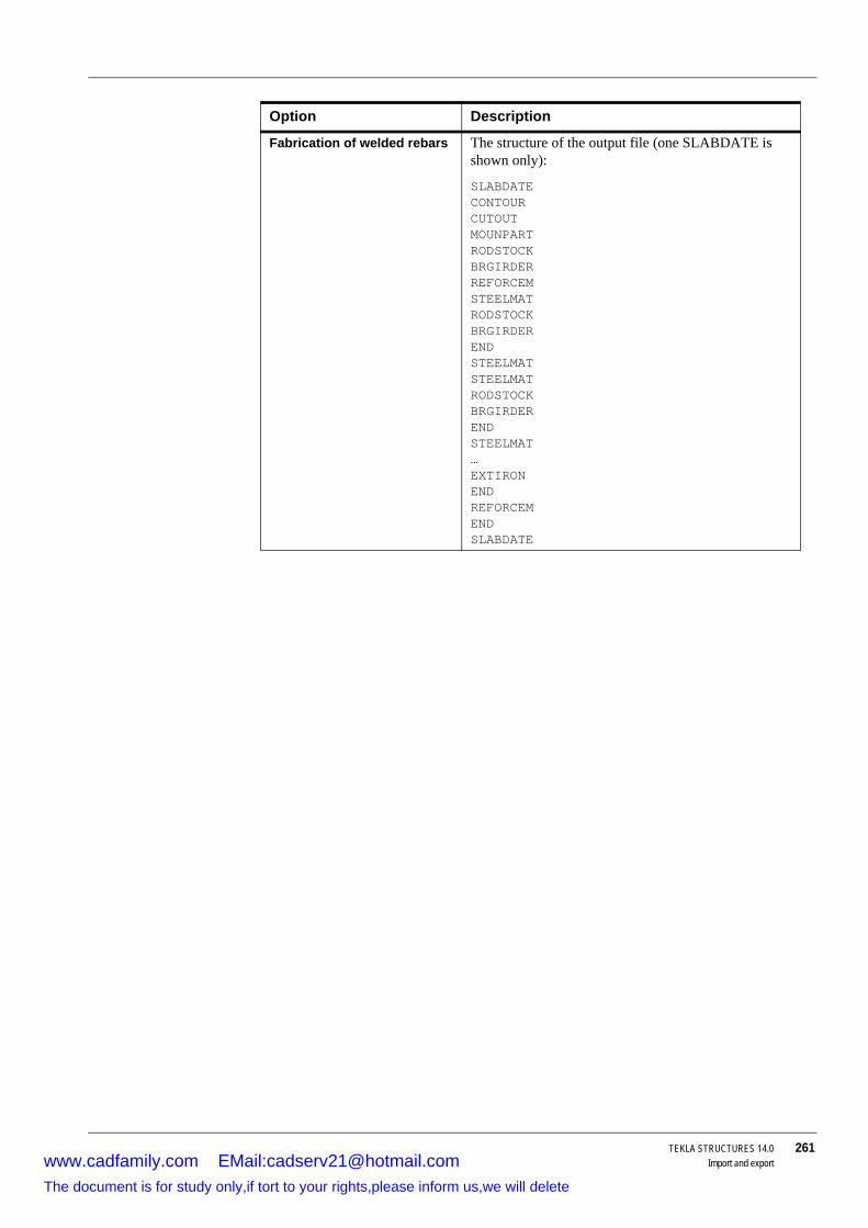
TEKLA STRUCTURES 14.0 261Import and export
Fabrication of welded rebars The structure of the output file (one SLABDATE is shown only):
SLABDATECONTOURCUTOUTMOUNPARTRODSTOCKBRGIRDERREFORCEMSTEELMAT RODSTOCK BRGIRDER END STEELMAT STEELMAT RODSTOCK BRGIRDER END STEELMAT … EXTIRON END REFORCEM END SLABDATE
Option Description
www.cadfamily.com EMail:[email protected] document is for study only,if tort to your rights,please inform us,we will delete

262 TEKLA STRUCTURES 14.0Import and export
Mesh defined by Parameter for automatic mesh collecting. Meshes with one bar are exported as a single reinforcing bar.
• ClassReinforcement with the same class number are collected into meshes. Reinforcement with one class number equals one mesh in the exported file.
• Name
Reinforcement with the same name are collected into meshes. Reinforcement with the same name equals one mesh in the exported file.
• UDA
Form mesh automatically The structure of the output file is the same as for Fabri-cation of welded rebars. This option allows you to collect mesh, single reinforcing bars and reinforcing bar groups into groups exported in one STEELMAT block. Collecting is made by Mesh defined by and Name UDA fields. Collecting of meshes which belong to different concrete cast units is supported.
1 (orange color) – the mesh belongs to the bottom panel of the cast unit, mesh name is MESH1.
2 (blue color) – two single bars, name is MESH1.
3 (green color) – one reinforcing bar group belongs to the top panel, name is MESH1.
If Export Type is set to Form mesh automatically and Mesh defined by is set to Name, all three different rein-forcement types are collected into one mesh, which is exported in one STEELMAT block.
Option Description
www.cadfamily.com EMail:[email protected] document is for study only,if tort to your rights,please inform us,we will delete

TEKLA STRUCTURES 14.0 263Import and export
Reinforcement with the same user-defined attribute (defined with Name of UDA property) are collected into meshes.
Name of UDA Specify the name of the user-defined attribute for the Mesh defined by property.
Data specificationThis describes the fields on the Data specification tab of the Export unitechnik (79) component.
Order name (HEADER block)
Fills order fields in the HEADER block with the selected data. The options are:
• Project number
• Project name
• Cast unit number
Project, line 3 content
Fills project information fields (3rd line) in the HEADER block with the selected data.
project, line 4 content
Fills project information fields (4rd line) in the HEADER block with the selected data.
Custom UDA or string
Information displayed in the project information fields of the HEADER block. The typed text depends on the selected option of the project, line 4 content. If the selected option is Project UDA, type in the name of the user-defined attribute, if it is User defined text, type in the text you like.
Braced girder type
Specify braced girder type in the BRGIRDER block in the exported file.
• Empty: no string exported • Name: the name of the braced girder type. If the name of the top part of the braced girder is
empty, checks the remaining bar names.
• UDA: the value of the user-defined attribute (defined by UDA name or string) is exported.
• String: the text defined by UDA name or string is exported.
UDA name or string
Specify the name of the user-defined attribute or text used in Braced girder type.
Slab number (SLABDATE BLOCK)
Specify filling of slab number field in the SLABDATE blocks. Options are:
• Counter
• Cast unit position
• Cast unit number
Overview of ELiPLAN import and exportDescription Elematic ELiPLAN is a software for resource planning, scheduling, and management for precast
concrete fabricators. Using the export and import features in Tekla Structures you can automate the data transfer between these two applications.
The data transfer consists of the following actions:
1. Exporting ELiPLAN data file from Tekla Structures2. Importing ELiPLAN data file into ELiPLAN
3. Exporting ELiPLAN status data file from Eliplan
4. Importing ELiPLAN status data file into Tekla Structures
www.cadfamily.com EMail:[email protected] document is for study only,if tort to your rights,please inform us,we will delete

264 TEKLA STRUCTURES 14.0Import and export
The ELiPLAN import (2) supports incremental approach, which means that ELiPLAN is able to create, update, and delete parts in it's database. This means that precast detailers can export the most up-to-date data files whenever the Tekla Structures model has been changed.
Similar incremental support is included in the Tekla import (4). To keep the status and schedule data in Tekla Structures model up-to-date, we recommend you to update the status data regularly.
See also Exporting ELiPLAN (p. 264)
Import ELiPLAN status data
Exporting ELiPLAN
Exporting to ELiPLAN
To export part data to ELiPLAN,
1. Press Ctrl + F to open the component catalog. 2. Type Eliplan and click Search.
3. Double-click Export data to EliPlan file to open the following dialog box.
4. Set Scope of export to All and click Create to export the file. For more information on the other properties, see the table below.
www.cadfamily.com EMail:[email protected] document is for study only,if tort to your rights,please inform us,we will delete

TEKLA STRUCTURES 14.0 265Import and export
Field Description
Scope of export Use to export all parts or only selected parts. Because of the incremental import of ELiPLAN you need to select the same parts (and some additional parts, if needed) again when exporting the next time. Otherwise ELiPLAN will think that the parts missing from the subsequent file have been deleted in the Tekla Structures model.
We recommend you to always use the All option. Use the Selected option only in special cases or when you are exporting parts for the first time.
Output file name The name of the export file created in the model folder. The default name is eliplan.eli. You can import this file into ELiPLAN.
Data conversion file With this file you can convert the parametric profile names into the ELiPLAN product codes, and the material descrip-tions into the ELiPLAN accessory codes. The default file name is eliplan_export.dat and this file can be located in your model, XS_FIRM or XS_PROJECT folder.
List of classes to be ignored (CIP)
A list of classes to exclude from the export. Typically this contains the class numbers used for cast-in-place concrete parts.
Export plotter data Use to include or exclude the plotter data in the exported file.
If you do not need this data in ELiPLAN, select No to exclude the data from the file and to reduce the file size.
Note that once you have transferred the file with the plotter data (Yes) you should never switch off (No) the export of plotter data in subsequent exports.
Export material data Use to include or exclude the detailed material data (receipt) of parts.
If you have no use for material data in ELiPLAN (you have no material handling module in ELiPLAN), select No to exclude the data from the file and to reduce the file size.
Note that once you have transferred the file with the mate-rial data (Yes) you should never switch off (No) the export of material data in subsequent exports. If you do this, the receipt is also cleared in the ELiPLAN database and all modifications are lost.
Export rebar bending data Use to include or exclude the detailed rebar bending infor-mation.
If you do not need this data in ELiPLAN, select No to exclude the data from the file and to reduce the file size.
Note that once you have transferred the file with the rebar bending data (Yes) you should never switch off (No) the export of rebar bending data in subsequent exports.
Create Click this button to export the data.
www.cadfamily.com EMail:[email protected] document is for study only,if tort to your rights,please inform us,we will delete

266 TEKLA STRUCTURES 14.0Import and export
See also Overview of ELiPLAN import and export (p. 216)
Import ELiPLAN status data
7.5 Exporting drawingsTo export Tekla Structures drawings as a DXF or DWG file:
1. Click Drawings & Reports > Drawing List....2. Select the drawings from the list.
3. Right-click and select Export... from the pop-up menu. The Export drawings dialog box is displayed.
4. On the Export file tab, browse for the file you want to export by clicking the Browse... button.
5. Select a file type: DXF or DWG.
6. Select the Include revision mark to file name check box if you want to include a revision mark in the file name.
7. Set the layer options as required on the Layer options tab. For more information, see Layers (p. 266).
8. Set the other options as required on the Options tab:
• If you want to export the drawing so that the DWG/DXF content is grouped by object, select the Export objects as groups check box. When you do this, Tekla Structures forms a new group for each object (part, mark, dimension line etc.).
• Set the Drawing scale and Line type scale.
• Select the Cut lines with text check box if you do not want to display continuous lines in exported drawings, for example, to run the line through text or drawing marks.
9. Click Export.
LayersUse the Layer options tab on the Export Drawings dialog box to define the layering options.
If you want to specify which layers different drawing objects belong to, click Setup.... The Drawing Export Layers dialog box is displayed.
Before you can transfer data to EliPlan you need to define how the product codes, types, and accessory codes (material description) are moved from the Tekla Structures model to ELiPLAN. For more informa-tion, see Configuration for ELiPLAN export.
www.cadfamily.com EMail:[email protected] document is for study only,if tort to your rights,please inform us,we will delete

TEKLA STRUCTURES 14.0 267Import and export
Organize the rules by right-clicking and using Move up and Move down. You cannot move the rule Other object type. This collects all the exported objects that do not match any other rules.
Changing layers To change a layer:
1. Right-click a layer item, and select Select layer.... The Select layer dialog box is displayed. 2. Select the desired layer.
3. Click OK.
Defining marks to their own layers
You can define marks to their own layers. This applies to all kinds of marks: bolt marks, part marks, connection marks, neighbour part marks, reinforcement marks and component marks. To do this:
1. Select the mark layer rule of the mark you want to define to its own layer in Layer rules. 2. Right-click and select Add next level rule from the pop-up menu.
3. Enter a rule name (for example, BeamMark) and select a filter (for example, beams) and click OK.
4. Tekla Structures creates the new rule BeamMark, which you can use when exporting drawings.
Advanced line type and layer conversion
You can use advanced conversion to convert the type, color and weight of lines and layers.
For more information, see Advanced line type and layer conversion (p. 268).
Rules define the drawing objects
Available layers
Click to modify layer names and color
www.cadfamily.com EMail:[email protected] document is for study only,if tort to your rights,please inform us,we will delete

268 TEKLA STRUCTURES 14.0Import and export
Copying settings To copy layer settings to another project:
1. Enter a name in the uppermost field.2. Click Save as.
3. Copy the file *.ldb from the current model folder to the firm or project folder. See also Folder search order (p. 94).
Advanced line type and layer conversionYou can use advanced conversion to convert the type, color and weight of lines and layers.
Usage 1. Select the Advanced line type and layer conversion check box on the Layer options tab in the Export Drawings dialog box.
2. Define the file to be used in the conversion in Conversion file.
Tekla Structures uses the file LineTypeMapping.xml in the folder ..\TeklaStructures\14.0\environments\country-independent\inp by default for the conversion.
If you need to define your own line type mappings, you can use the file LineTypeMapping.xml as a template. For more information, see Defining your own line type mappings (p. 268).
Defining your own line type mappingsIf you need to define your own line type mappings, you can use the file LineTypeMapping.xml in the folder ..\TeklaStructures\14.0\environments\country-independent\inp as a template. To define your own line type mappings:
1. Open the mapping file using a text editor.
2. Add your own definitions.
Some mappings have been predefined in the mapping file. Use these mappings as a template for your own mappings. You have two options for defining the mappings:
• Mapping according to line types only, for example all lines in all layers with line type XKITLINE01 will be exported to DASHED.
• Mapping according to line types and layer, for example all lines on the layer BEAM with line type XKITLINE01 will be exported to
DASHED. Tekla Structures first searches for this kinds of mappings by default.
This is how the file LineTypeMapping.xml is composed:
The font name used in Tekla Structures is used to form the name of the text style in AutoCAD. Use dxf_fonts.cnv conversion file to define which font file will be connected to the created AutoCAD style.
See also Conversion files (p. 192).
We recommend that you use an editor that is capable to validate XML in order to maintain the structure of the document valid.
www.cadfamily.com EMail:[email protected] document is for study only,if tort to your rights,please inform us,we will delete

TEKLA STRUCTURES 14.0 269Import and export
The first section consists of XML and document type definition. Do not change or remove this section.The mappings that are available are defined here. You can use these mappings as a template for your own mappings.
www.cadfamily.com EMail:[email protected] document is for study only,if tort to your rights,please inform us,we will delete

270 TEKLA STRUCTURES 14.0Import and export
In the following example, a new Mapping element is added to the file, where XKITLINE00 lines in the Beam layer are converted to BORDER type, color is converted to 10 and weight to 1.00 mm:
• For the list of available line types, see the TeklaStructures.lin file, which is located in the ..\TeklaStructures\14.0\environments\country-independent\inp folder. You can open and edit the file using any text editor.
The table below describes which line type name corresponds to which line type appearance.
• Define the color of the line in the Color attribute. Enter the color values in AutoCAD Color Index (ACI) codes (numbers from 0 to 255).
• Define the thickness of the line in the Weight attribute. Enter the values in hundredths of millimeters.
• Define the layers that the mapping will apply to in the LayerName attribute.
• If you leave out the attribute LayerName, Tekla Structures uses the line type mapping for any layer. If you include the attribute LayerName, Tekla Structures uses the line type mapping for that layer only.
3. Save the mapping file to the model folder of the model whose drawing you want to export.
Exporting hidden lines
You can use the LineTypeMapping.xml file also for exporting hidden lines to separate layers in DWG/DXF export.
Define the hidden lines to their own layers. In the following example, a Mapping element is added to the file, where XKITLINE02 lines in the Part layer are converted to HIDDEN2 type, and the layer name is converted to Part_Hidden.
Line type name Line type appearance
XKITLINE00
XKITLINE01
XKITLINE02
XKITLINE03
XKITLINE04
XKITLINE05
XKITLINE06
www.cadfamily.com EMail:[email protected] document is for study only,if tort to your rights,please inform us,we will delete

TEKLA STRUCTURES 14.0 271Import and export
7.6 Reference modelsA reference model is a file which helps you to build a Tekla Structures model. The following file types are supported:
• AutoCAD (*.dxf) • AutoCAD (*.dwg)
• MicroStation (*.dgn, *.prp)
• Cadmatic models (*.3dd)
• IFC files (*.IFC)
• WebViewer XML files (*.xml)
The reference model appears in the background of your Tekla Structures model. You can snap to reference model points. Tekla Structures loads the reference model from file each time you open your model. It does not save the reference model when you save the current model. The filename extension of a saved reference model properties file is rop.
Topics Using a reference model (p. 271)
Using several reference models (p. 272)
Handling large reference models (p. 273)
Supported DGN objects (p. 277)
Using a reference modelTo use a reference model in a Tekla Structures model:
1. Open a Tekla Structures model.2. Check the work plane position. This determines the rotation of the reference model in the
Tekla Structures model.
3. Double-click the Insert reference model icon.
4. Use Browse... to locate the reference model file.
5. Set the scale of the reference model, if it is different to the one in the Tekla Structures model (for example, if they use different measurement units).
6. Click Apply or OK to save the current reference object properties.
7. Pick the position for the reference model origin.
For the export to succeed, make sure that the Part_Hidden layer exists on the list of available layers in the Modify Layers dialog box.
www.cadfamily.com EMail:[email protected] document is for study only,if tort to your rights,please inform us,we will delete

272 TEKLA STRUCTURES 14.0Import and export
See also Using several reference models (p. 272)
Reference objects in drawings
XS_REFERENCE_CACHE (p. 377)
Using several reference modelsYou can use several reference models in one Tekla Structures model.
To check which reference models are included in a model, click File > Reference Model List.... Select a reference model object in the dialog box to have Tekla Structures highlight it in the model.
Use the Reference Models dialog box to:
• Show or hide reference models using the Visibility field• View user-defined attributes of reference objects. To modify user-defined attributes,
double-click an object on the list to open the Reference Model Properties dialog box, then click User-defined attributes.
View filter You can also use the view filter to define which reference models are visible in each view.
To hide a reference model in a view.
Find out the ID of the reference model to hide:
1. Click Tools > Inquire > Object.2. Click the reference model you want to hide. The Inquire Object dialog box appears.
3. Copy the ID number.
4. Interrupt the command.
Select the view where you want to hide the reference model:
1. Double-click the view to display the view properties.2. In the View Properties dialog box, click Object group....
3. Click the Add row button to add a new row.
4. In the Category column, select Reference object.
5. In the Property column, select Id number.
6. In the Condition column, select Does not equal.
7. In the Value column, enter the ID number. To hide several reference models, separate their IDs with spaces.
8. Click Modify.
If you do not define the reference model file to use, or it does not exist, Tekla Structures displays a default reference model.
You must define user-defined attributes in the objects.inp file. See Adding properties (p. 98).
www.cadfamily.com EMail:[email protected] document is for study only,if tort to your rights,please inform us,we will delete
TEKLA STRUCTURES 14.0 273Import and export
See also Using a reference model (p. 271).
Updating reference modelsYou can update the reference models in your Tekla Structures model in case there have been changes in the original reference models after you have brought them into Tekla Structures.
To update all reference models:
Usage 1. Click File > Reference Model List...2. Click Reload all.
When you click Reload all, Tekla Structures goes through all the reference models and regenerates the cache for the reference models that have a newer modified date than the one already in the cache.
Handling large reference modelsThis section contains tips for speeding up large reference models.
• To open the Reference object properties dialog box, click File > Reference objects...
• Select the reference model and set Visibility to Wireframe.
• Switch off Xsnap. It affects picking speed, because one dgn file is one solid object and it takes time to find correct picking point.
• Split large dgn files into smaller ones.
• Use fewer segments to represent round reference objects. Set the variable XS_REFERENCE_ROUND_SEGMENTS=8. Default is 16 segments.
Easier viewing In rendered views, only view reference model objects as rendered inside the work area. This feature is designed solely for DGN cylindrical structures, like piping. To do this, set the variable XS_REFERENCE_USE_RENDERED_CLIPPING=TRUE.
Tekla Structures then shows the objects as follows:
• Objects entirely inside work area are rendered.• Objects entirely outside work area are hidden.
• Objects partly inside the work area are rendered inside work area, and wireframe outside work area.
Gray reference models
View all reference model objects in gray by setting the variable
XS_REFERENCE_DGN_READ_COLORS=FALSE
Detecting changes in reference modelsReference models are often updated, but the changes are rarely documented. You can see the changes between an old and a new reference model in Tekla Structures by using the commands in the Reference Object Properties dialog box.
You can choose to display one of the following:
• The new file• The old file
• Unchanged objects
www.cadfamily.com EMail:[email protected] document is for study only,if tort to your rights,please inform us,we will delete

274 TEKLA STRUCTURES 14.0Import and export
• Changed objects
• Deleted objects
• Inserted objects
Usage 1. Select the reference model and double-click it to display the Reference Object dialog box.
2. Browse for the name of the old file by clicking the Browse... button next to the Old file name field.
3. Select an option in the Show list box in the Change detection section. For example, select Changed to see the changed objects in a reference model.
4. Click Display. Tekla Structures highlights the changed reference model objects.5. Click Modify to stop detecting the changes.
Example In the following example you will see the how the changes are displayed in the reference model.
The old file:
You can detect changes in reference models that are of the following file formats:
• IFC (.ifc)• Cadmatic (.3dd)
• WebViewer (.xml)
• DWG (.dwg)
www.cadfamily.com EMail:[email protected] document is for study only,if tort to your rights,please inform us,we will delete

TEKLA STRUCTURES 14.0 275Import and export
The new file:
The Show option has been set to Changed in the Reference Object Properties dialog box:
The Show option has been set to Inserted in the Reference Object Properties dialog box:
www.cadfamily.com EMail:[email protected] document is for study only,if tort to your rights,please inform us,we will delete

276 TEKLA STRUCTURES 14.0Import and export
The Show option has been set to Deleted in the Reference Object Properties dialog box:
Reference model objectsYou can split reference models into separate reference model objects. Reference model objects can have separate user-defined attributes that can then be used for reports and view and select filters.
Restrictions The use of this functionality depends on the file format and file structure. You can use it for example for IFC and for DWG files that include any of the following objects:
• block table• polyface mesh
• polygon mesh
• proxy object (for example, ADT)
• ACIS objects (3DSolid, Body, Region)
See also Selecting reference models and reference model objects (p. 276)
Listing reference models and reference model objects in reports (p. 277)
Selecting reference models and reference model objectsYou can define whether to select reference models or reference model objects.
You cannot use this functionality for DGN files.
www.cadfamily.com EMail:[email protected] document is for study only,if tort to your rights,please inform us,we will delete

TEKLA STRUCTURES 14.0 277Import and export
Selecting reference models
To select a reference model:
1. Activate the Select component switch.2. Select the reference model.
Selecting reference model objects
1. Activate the Select objects in components switch.2. Select the desired object in the reference model.
See also Selecting model objects
Listing reference models and reference model objects in reportsYou can list reference models and reference model objects separately in reports.
Listing reference models
To list reference models in reports, use the content type REFERENCE_MODEL.
Listing reference model objects
To list reference model objects in a reference model in reports, use the content type REFERENCE_OBJECT.
See also Content type (p. 423)
Supported DGN objectsTekla Structures can display the following DGN objects in reference models:
• Line Elements (Type 3)• Line String (Type 4)
• Shape (Type 6)
• Text Nodes (Type 7)
• Curve (Type 11)
• Complex Chains (Type 12)
• Complex Shapes (Type 14)
• Elliptic Elements (Type 15)
• Arc Elements (Type 16)
• Text Elements (Type 17)
• Surfaces (Type 18)
• Solids (Type 19)
• Point String Elements (Type 22)
• Cone Elements (Type 23)
• B-spline Surfaces (Type 24)
• B-spline Curves (Type 27)
• Shared Cells (Type 34, 35)
• Mesh Elements (Type 105), subtype "Indexed Face Loops"
www.cadfamily.com EMail:[email protected] document is for study only,if tort to your rights,please inform us,we will delete

278 TEKLA STRUCTURES 14.0Import and export
7.7 Tekla WebViewerYou can publish your Tekla Structures models as web pages that can be viewed via the Internet using a web browser (e.g. Internet Explorer).
Topics Publishing a model as a web page (p. 278)
Web templates (p. 279)
Emailing WebViewer models (p. 279)
Handling named views (p. 280)
Handling clip planes (p. 281)
Hiding and showing objects (p. 282)
Full content rendering (p. 282)
Publishing a model as a web pageTo publish a Tekla Structures model as a web page:
1. Click File > Publish as Web page.... The following dialog box appears:
The following DGN objects are not supported:
• Dimension Elements (Type 33) • Multiline Elements (Type 36)
• Mesh Elements (Type 105), other subtypes than "Indexed Face Loops"
SmartSolid elemets are supported as WireFrame only.
www.cadfamily.com EMail:[email protected] document is for study only,if tort to your rights,please inform us,we will delete

TEKLA STRUCTURES 14.0 279Import and export
2. In the File name field, enter the destination path and file name for the published model.
3. Click Publish. If you select the Open in browser checkbox, the model opens in your web browser.
By default, Tekla Structures creates a PublicWeb folder with sub-folders in the current model folder, and places the published model there as an index.html file.
When you open the model in a web browser, it includes several commands for examining the model. You can also right-click the model in the browser to access a pop-up menu containing these commands.
Web templatesThe sub-folders under ..\ TeklaStructures\*version*\nt\WebTemplates\TeklaWebViewer contain all Tekla Web Viewer specific materials, for example, a tool (*.dll) for viewing the model, and templates for HTML files. When you publish a model as a web page, Tekla Structures copies the tool and files to the folder you have specified in the File name field. You cannot modify the tool, but you can modify the HTML files to include information relevant to your firm and project.
You can use project-specific template fields in the HTML files. Just insert them, surrounded by % characters, in an HTML file in the Tekla Web Viewer folder. Tekla Structures replaces them with the current information from the model you are publishing.
Example When you want the project name to show in the Web Viewer model, insert the string %NAME% in an HTML file. When you publish models as a web page, Tekla Structures takes the project name information from the Project properties dialog box.
Emailing WebViewer modelsTo email a published model:
1. Zip the entire PublicWeb folder. Remember to use the folder structure.2. Attach the .zip file to an e-mail message and send it to the recipient. The recipient can
then unzip the files and save the contents.
See also Receiving WebViewer models (p. 279)
Receiving WebViewer modelsWhen you receive a zipped WebViewer model, ensure you keep the folder names when you unzip it. To open the model, double-click the index.html file.
You can choose the location and name for the published model folder and rename the published file but do not change the file name extension.
Do not remove the string %PUBLISHED_MODEL% from the index.html file. Tekla Structures replaces it with the file name information from the dialog box.
www.cadfamily.com EMail:[email protected] document is for study only,if tort to your rights,please inform us,we will delete

280 TEKLA STRUCTURES 14.0Import and export
See also Sending WebViewer links (p. 280)
Handling named views (p. 280)
Handling clip planes (p. 281)
Hiding and showing objects (p. 282)
Full content rendering (p. 282)
How to move and zoom? (p. 282)
Sending WebViewer linksThere are two ways to send links from Tekla WebViewer:
• Send WebViewer link
• Send URL link
Send WebViewer link
Use this tool to send a link to a single Tekla Structures view. To see the view name in the Named views list, the receiver copies the text string and pastes it into the WebViewer model.
See also Receiving WebViewer models (p. 279).
Send URL link Use this tool to send a URL link to the model. Recipients must have access to the folder containing your published model.
Handling named viewsTo create named views from a published model,
1. Open the index.html for the published model.2. Zoom in on the part of the model from which you want to create the view.
3. Right-click and select Copy location.
4. Create a new file in any text editor (for example, Notepad) and paste the location information into it. It should look like this:
5. The default name for the view is xyz. To change it, in your text editor, replace the text xyz with the view name that you want to use.
6. Now you need to copy the updated location information to the published model. Select all the text in the text editor, right-click and select Copy.
7. In WebViewer, right-click on the model and select Paste location. The view name appears on the Named views list.
To send several views, copy the text strings pointing to the views into a text file and send the text file. The receiver then copies the contents of the text file and pastes it into the WebViewer model.
www.cadfamily.com EMail:[email protected] document is for study only,if tort to your rights,please inform us,we will delete
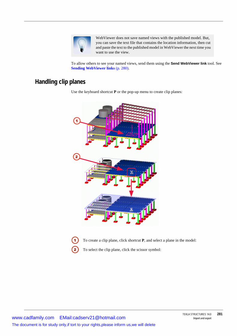
TEKLA STRUCTURES 14.0 281Import and export
To allow others to see your named views, send them using the Send WebViewer link tool. See Sending WebViewer links (p. 280).
Handling clip planesUse the keyboard shortcut P or the pop-up menu to create clip planes:
WebViewer does not save named views with the published model. But, you can save the text file that contains the location information, then cut and paste the text to the published model in WebViewer the next time you want to use the view.
To create a clip plane, click shortcut P, and select a plane in the model:
To select the clip plane, click the scissor symbol:
www.cadfamily.com EMail:[email protected] document is for study only,if tort to your rights,please inform us,we will delete

282 TEKLA STRUCTURES 14.0Import and export
Moving clip planes
Hiding and showing objectsUse the mouse wheel to hide and show objects:
• To hide objects, move the cursor over the objects, hold down the Ctrl key and scroll up (or press the Page Up key).
• To unhide object, move the cursor over the hidden objects, hold down the Ctrl key and scroll down (or press the Page Down key).
• Press the Esc key to show all objects.
Full content renderingTo handle large models faster, make full content rendering unavailable:
• Right-click and select Disable full content rendering from the pop-up menu. • To enable full content rendering, select Enable full content rendering from the pop-up
menu.
How to move and zoom?Use the following commands to move and zoom in a model:
Move the clip plane by dragging the scissor symbol.
You can change the location of the symbol by holding down the Shift key and moving the symbol.Select one clip plane and press space bar to jump between clip planes.
www.cadfamily.com EMail:[email protected] document is for study only,if tort to your rights,please inform us,we will delete

TEKLA STRUCTURES 14.0 283Import and export
Command (Shortcut) Action/Description
Zoom Click Page Up or Page Down keys, or scroll mouse wheel forward to zoom in, and backward to zoom out.
Pan (P) Click Pan and drag, or drag with the mouse middle button.
Rotate (Ctrl + R, Shift ? R, Shift + T)
Totate with mouse (Ctrl + R), rotate model one round (Shift + R) or rotate the model continuously (Shift + T).
Fly (Shift+F) Click Fly and move the mouse forward to fly forward. To change flying direction, move the mouse to the desired direction.
To stop, click Esc.Center (Ins) Centers the model on the screen.Home (Home) Returns the model to the original
view.Set view point (V) Use to relocate the center of rotation.
1. Press the V key. 2. Click to pick the new center of
rotation.
3. Hold down the Ctrl key and drag with the middle mouse button.
You can also right-click the model and select the move and zoom commands from the popup menu.
www.cadfamily.com EMail:[email protected] document is for study only,if tort to your rights,please inform us,we will delete

284 TEKLA STRUCTURES 14.0Import and exportwww.cadfamily.com EMail:[email protected]
The document is for study only,if tort to your rights,please inform us,we will delete

TEKLA STRUCTURES 14.0 285Variables
8 Variables
Introduction Tekla Structures includes several variables that you can use to customize your version of Tekla Structures. For example, you can choose to use imperial units by setting a variable.
The variables are grouped in different categories according to their usage in the Advanced options dialog box. To access the dialog box, click Tools > Options > Advanced options....
You can also use initialization files for setting variables. For more detailed information, see Setting variables (p. 80). We recommend that you only use one of these methods to set variables.
Topics List of variables (p. 285)
Categories in the Advanced Options dialog box (p. 285)
User variables (p. 286)
See also About variables (p. 80)
Setting variables (p. 80)
8.1 List of variablesClick on a letter below to see a list of variables that begin with that letter, ignoring the initial letters XS. For example, under A you will find the variable XS_AISC_WELD_MARK, under B, XS_BACKGROUND_COLOR,etc.
Variables starting with XSR are listed under R. They control how Tekla Structures displays imperial units in reports and drawing tables.
Categories in the Advanced Options dialog boxThe Advanced Options dialog box groups variables in the following categories:
A B C D E F G H I J K L
M N O P R S T U V W Z
www.cadfamily.com EMail:[email protected] document is for study only,if tort to your rights,please inform us,we will delete

286 TEKLA STRUCTURES 14.0Variables
• Analysis & Design
• CNC
• Components
• Concrete Detailing
• Dimensioning: General
• Dimensioning: Bolts
• Dimensioning: Parts
• Dimensioning: Unfolding
• Drawing Properties
• Drawing View
• Export
• File Locations
• Hatching
• Imperial Units
• Import
• Marking: General
• Marking: Bolts
• Marking: Parts
• Model View
• Modeling Properties
• Multi-user
• Numbering
• Plate Work
• Printing
• Profiles
• Single Part View in Assembly Drawing
• Speed and Accuracy
• Templates and Symbols
• Welds
See also About variables (p. 80)
Setting variables (p. 80)
User variablesTekla Structures saves the settings for the following variables in the options_username.ini file:
www.cadfamily.com EMail:[email protected] document is for study only,if tort to your rights,please inform us,we will delete

TEKLA STRUCTURES 14.0 287Variables
• XS_AUTOSAVE_DIRECTORY
• XS_BACKGROUND_COLOR
• XS_BASICVIEW_HEIGHT
• XS_BASICVIEW_POSITION_X
• XS_BASICVIEW_POSITION_Y
• XS_BASICVIEW_WIDTH
• XS_CHAMFER_DISPLAY_LENGTH_FACTOR
• XS_CLASH_CHECK_COLOR
• XS_CLEAR_MODEL_HISTORY
• XS_DEFAULT_FONT_SIZE
• XS_DEFAULT_FONT
• XS_DISABLE_PARTIAL_REFRESH
• XS_DO_NOT_CHECK_DIMENSION_POINTS
• XS_DO_NOT_DISPLAY_CHAMFERS
• XS_DO_NOT_PLOT_DIMENSION_POINT_CIRCLES
• XS_DONT_SHOW_POLYBEAM_MID_EDGES
• XS_DRAWING_SHEET_HEIGHT
• XS_DRAWING_SHEET_POSITION_X
• XS_DRAWING_SHEET_POSITION_Y
• XS_DRAWING_SHEET_WIDTH
• XS_FILTER_SEPARATOR_CHAR
• XS_GRID_DIMENSION_OVERALL_LENGTH
• XS_HIDDEN_USE_BOLT_PLANES
• XS_IMPORT_MODEL_LOG
• XS_KEEP_AUTOSAVE_FILES_ON_EXIT_WHEN_NOT_SAVING
• XS_KEYIN_ABSOLUTE_PREFIX
• XS_KEYIN_DEFAULT_MODE
• XS_KEYIN_RELATIVE_PREFIX
• XS_MACRO_LOG
• XS_MDIBASICVIEWPARENT
• XS_MDIVIEWPARENT
• XS_MDIZOOMPARENT
• XS_NO_AUTO_DISPLAY_VIEWS
• XS_NO_CHAMFERS_IN_EXACT_MODE
• XS_PIXEL_TOLERANCE
www.cadfamily.com EMail:[email protected] document is for study only,if tort to your rights,please inform us,we will delete

288 TEKLA STRUCTURES 14.0Variables
• XS_PROFILE_ANALYSIS_CHECK_ALL
• XS_PROFILE_ANALYSIS_VALUE_DIFF_LIMIT
• XS_REFERENCE_DGN_READ_COLORS
• XS_REFERENCE_DGN_READ_LINES
• XS_REFERENCE_ROUND_SEGMENTS
• XS_REFERENCE_USE_RENDERED_CLIPPING
• RPC_WAIT_TIME
• XS_SHOW_REVISION_MARK_ON_DRAWING_LIST
• XS_SNAPSHOT_DIRECTORY
• XS_SOLID_BUFFER_SIZE
• TEXT_X_SIZE
• TEXT_Y_SIZE
• XS_TEXT_FONT
• XS_USE_DRAWING_NAME_AS_PLOT_TITLE
• XS_USE_MULTI_NUMBERING_WHEN_COPYING_DRAWING_VIEWS
• XS_USE_ONLY_INCHES_IN_SHEET_SIZES
• XS_USE_ONLY_INCHES_IN_WELD_LENGTH
• XS_USE_SMOOTH_LINES
• XS_USE_SOFTWARE_RENDERING
• XS_VIEW_HEIGHT
• XS_VIEW_POSITION_X
• XS_VIEW_POSITION_Y
• XS_VIEW_WIDTH
• XS_ZOOM_STEP_RATIO_IN_MOUSEWHEEL_MODE
• XS_ZOOM_STEP_RATIO_IN_SCROLL_MODE
• XS_ZOOM_STEP_RATIO
• XS_CIS_DEP1_EXPRESS_FILE
• XS_POP_MARK_EDGE_DISTANCE
See also About variables (p. 80)
Setting variables (p. 80)
www.cadfamily.com EMail:[email protected] document is for study only,if tort to your rights,please inform us,we will delete

TEKLA STRUCTURES 14.0 289Variables
8.2 A
XS_AD_CURVED_BEAM_SPLIT_ACCURACY_MMCategory Analysis & Design
Use to set the maximum distance between a curved member and straight segment. The default is 25 mm.
See also XS_AD_CURVED_BEAMS_BY_STRAIGHT_SEGMENTS
XS_AD_CURVED_BEAMS_BY_STRAIGHT_SEGMENTSCategory Analysis & Design
Set to TRUE to model curved beams as straight segments in the analysis model. Using straight segments ensures that releases are supported for curved beams. The default is TRUE.
When set to FALSE, straight segments are not used.
See also XS_AD_CURVED_BEAM_SPLIT_ACCURACY_MM
XS_AD_DISABLE_EDITING_BY_UDACategory Analysis & Design
Use to negate the effect of the following user-defined attributes on analysis models:
• Member level• Node offset X
• Node offset Y
• Node offset Z
See also Fine-tuning analysis model
XS_AD_ELEMENT_ANGLE_CHECK_ANGLE_DIFF_LIMITCategory Analysis & Design
Use to set a limit angle between physical part and analysis model member, in order to test the validity of the analysis model. When the angle is greater than the limit, a message appears and a warning is added to the log. Small differences in angles are usual in the analysis model of a truss, for example.
XS_AD_ENABLE_PLATE_CANTILEVER_REMOVALCategory Analysis & Design
www.cadfamily.com EMail:[email protected] document is for study only,if tort to your rights,please inform us,we will delete

290 TEKLA STRUCTURES 14.0Variables
Set to TRUE to simplify the analysis model on the edges of plates that are shorter than the limit value set by the variable XS_AD_PLATE_CANTILEVER_REMOVAL_LIMIT_MM.
A typical example is a slab supported by a beam close to the slab edge, so that the beam centerline is located 100–200 mm from the slab edge.
When the analysis model is generated for the slab, nodes appear in the beam centerline and too many nodes and small elements appear in the area between the centerline and the edge (cantilever). Typically the cantilever area is not required in the calculation, so this option tries to remove that area.
XS_AD_MEMBER_NUMBER_VISUALIZATIONCategory Analysis & Design
Use to show or hide member numbers when displaying the analysis model in a model view. The default is TRUE, which shows the numbers.
See also Showing analysis models and support conditions in model views
XS_AD_MEMBER_TYPE_VISUALIZATIONCategory Analysis & Design
Use color to show different analysis member types when displaying the analysis model in a model view. A setting of FALSE shows the analysis members in red. The default setting is TRUE. This identifies analysis members using the following colors:
• Red = normal member• Gray = composite beam
• Green = truss member
• Violet = truss member, tension only
• Yellow = truss member, compression only
• Dark blue = rigid link
• Light blue = plate, slab, or panel edge
See also Showing analysis models and support conditions in model views
XS_AD_NODE_COLLISION_CHECK_DISTANCECategory Analysis & Design
www.cadfamily.com EMail:[email protected] document is for study only,if tort to your rights,please inform us,we will delete

TEKLA STRUCTURES 14.0 291Variables
To make members meet in analysis models, Tekla Structures merges analysis nodes. Tekla Structures will not merge nodes that are farther apart then the value you specify in this variable. The default is 10 mm.
XS_AD_NODE_NUMBER_VISUALIZATIONCategory Analysis & Design
Use to show or hide node numbers when displaying the analysis model in a model view. The default is TRUE, which shows the numbers.
See also Showing analysis models and support conditions in model views
XS_AD_OPTIMISATION_DISABLEDCategory Analysis & Design
Use to check profile catalog analysis values. For more information, see XS_PROFILE_ANALYSIS_CHECK_ALL.
XS_AD_OPTIMISATION_RECURSE_CATALOGCategory Analysis & Design
Set to TRUE to have Tekla Structures ignore profile catalog rules for optimizing steel part sizes and search the entire profile catalog.
XS_AD_PLATE_CANTILEVER_REMOVAL_LIMIT_MMCategory Analysis & Design
Sets the limit distance for cantilever area to be removed from the slab or plate edge in the analysis. For more information, see XS_AD_ENABLE_PLATE_CANTILEVER_REMOVAL.
XS_AD_PLATE_MESH_CHECK_DISTANCE_LIMITCategory Analysis & Design
Use to define the distance at which Tekla Structures considers nodes to be too close. The default value is 100 mm. When nodes are too close to each other in slab or wall meshes, Tekla Structures writes information to the analysis.log file.
To define the distance within which Tekla Structures considers nodes to be too close, use this variable.
To restrict the distance check to a particular object, enter the object ID in the Value field for the variable XS_AD_PLATE_MESH_CHECK_PART_ID. The default value is 0.
Tekla Structures writes three rows in the analysis.log file:
• The first row contains information on parts, for example: "Mesh point distances less than the specified limit for PartId: 123"
• The second row contains information on the first node, for example: " NodeId: 456, x = 100.0000, y = 200.0000, z = 10000.000"
www.cadfamily.com EMail:[email protected] document is for study only,if tort to your rights,please inform us,we will delete
292 TEKLA STRUCTURES 14.0Variables
• The third row contains information on the second node, and distance, for example: " ->NodeId: 789, x = 150.0000, y = 200.0000, z = 10000.000, distance = 50.0000"
When you click a line in the log file that contains an object ID, Tekla Structures highlights the object in the model.
XS_AD_PLATE_MESH_CHECK_PART_IDCategory Analysis & Design
Use to restrict the distance check in slab or wall mesh nodes to a particular object. For more information, see XS_AD_PLATE_MESH_CHECK_DISTANCE_LIMIT.
XS_AD_RESULT_DATABASE_ENABLEDCategory Analysis & Design
Use to define whether the analysis results database analysis_results.db5 is created or not. The default setting is TRUE. This creates the analysis results database.
If you decide not to create the analysis results database, set this variable to FALSE. In this way the use of large models with several load combinations is faster and less memory consuming.
XS_AD_SOLID_AXIAL_EXPAND_MMExtended clash check is the default method when creating analysis models. By default this expands solids by 1 mm in all directions, including the axial direction. Use this variable to define how much solids expand in the axial direction.
XS_AD_SUPPORT_VISUALIZATIONCategory Analysis & Design
Use to show or hide the support conditions when showing the analysis model in a model view. The default is TRUE, which shows the support conditions.
See also Showing analysis models and support conditions in model views
XS_AD_TWIN_PROFILES_ENABLEDCategory Analysis & Design
Use to enable or disable the twin profile support in analysis and design. To treat twin profiles as one member in the analysis, set to TRUE. When set to FALSE, Tekla Structures creates two analysis members of the twin profiles in the analysis model.
XS_ADJUST_GRID_LABELSCategory Model view
To disable the dynamic moving of grid labels when zooming in, and to keep the labels anchored to the end of the grid line, set the variable to FALSE. By default, the grid line labels are kept visible. When working with very large grids, having the grid labels always visible might slow down Tekla Structures. After you change the variable setting, close and re-open the view to implement the change.
www.cadfamily.com EMail:[email protected] document is for study only,if tort to your rights,please inform us,we will delete

TEKLA STRUCTURES 14.0 293Variables
XS_AISC_WELD_MARKCategory Welds
Set to 1 to create welding marks according to the AISC standard, instead of the ISO standard (Default).
AISC weld symbols show the arrow-side weld properties below the reference line in a weld symbol, and the other-side properties above it.
XS_ALIGN_CUT_SYMBOL_BY_VERTICAL_LINECategory Drawing properties
Set to TRUE to have Tekla Structures align the cut symbol with the vertical cut line.
When you set the variable to TRUE, the value of the longitudinal offset is 0. If the variable is not set, the longitudinal offset is the arrow size multiplied by 1.25.
XS_ALLOW_DRAWING_TO_MANY_MULTI_DRAWINGSCategory Numbering
The variable is set to TRUE. Use this option when you need to see the exact location of the section view.The variable is not set. Use this option when it is important to see the direc-tion rather than the exact location of the section view.
The variable XS_ALIGN_CUT_SYMBOL_BY_VERTICAL_LINE is effec-tive only when you convert drawings created with Tekla Structures 11.3 or earlier to Tekla Structures 12.0 or later.
www.cadfamily.com EMail:[email protected] document is for study only,if tort to your rights,please inform us,we will delete

294 TEKLA STRUCTURES 14.0Variables
Assign any value to this variable to enable the same drawings to be included in more than one multi-drawing.
If this variable is disabled, you can only include each drawing in one multi-drawing.
XS_ALLOW_INCH_MARK_IN_DIMENSIONSCategory Dimensioning: general
Set to TRUE to have Tekla Structures include the inch symbol in dimensions.
XS_ALLOW_INCH_MARK_IN_WELD_SYMBOLSCategory Imperial units
Set to TRUE to have Tekla Structures include the inch symbol in weld symbols.
XS_ALLOW_SHEAR_PLATE_CLASH_FLANGECategory Components
Set to TRUE to omit the default 0.3mm tolerance between shear plate and secondary part web for shear plate components.
XS_ALWAYS_CONFIRM_SAVE_WHEN_CLOSING_DRAWINGCategory Drawing properties
If you close a drawing without making any changes, Tekla Structures does not prompt you to save the drawing.
Enter TRUE in the value field to always display the confirmation dialog box:
XS_ALWAYS_CONFIRM_SAVE_WHEN_EXITCategory Modeling Properties
Use to define whether or not Tekla Structures prompts you to save the model if you are closing it without making any changes.
If the value is set to TRUE, Tekla Structures always asks you to save the model when closing it.
If the value is set to FALSE, Tekla Structures does not ask you to save the model if there are no changes after the last save.
The default value is TRUE.
www.cadfamily.com EMail:[email protected] document is for study only,if tort to your rights,please inform us,we will delete

TEKLA STRUCTURES 14.0 295Variables
XS_ANCHOR_BOLT_PLAN_ADDITIONAL_PARTS_FILTER
Category Drawing Properties
Use to add additional parts that are not usually part of a column assembly to an anchor bolt plan, such as anchor rods or leveling plates. First define a general arrangement drawing filter and then define that filter name as the value for this variable.
See also Adding additional parts in anchor bolt plan using a drawing filter
XS_ANCHOR_BOLT_PLAN_BASEPLATE_FILTERCategory Drawing Properties
Use to limit the number of visible objects by using filtering to determine the parts to be included in the anchor bolt plan. First create the base plate filter, then enter its name as the value for the variable. Tekla Structures will not show in the anchor bolt plan the base plates included in the filter.
Example XS_ANCHOR_BOLT_PLAN_BASEPLATE_FILTER=<the name of the filter for base plates>
XS_ANCHOR_BOLT_PLAN_BOLT_FILTERCategory Drawing Properties
Use to limit the number of visible objects by using filtering to determine the parts to be included in the anchor bolt plan. First create the bolt filter, then enter its name as the value for the variable. Tekla Structures will not show in the anchor bolt plan the bolts included in the filter.
Example XS_ANCHOR_BOLT_PLAN_BOLT_FILTER=<the name of the filter for bolts>
XS_ANCHOR_BOLT_PLAN_COLUMN_FILTERCategory Drawing Properties
Use to limit the number of visible objects by using filtering to determine the parts to be included in the anchor bolt plan. First create the column filter, then enter its name as the value for the variable. Tekla Structures will not show in the anchor bolt plan the columns included in the filter.
Example XS_ANCHOR_BOLT_PLAN_COLUMN_FILTER=<the name of the filter for columns>
XS_ANCHOR_BOLT_PLAN_DRAWING_TOLERANCECategory Drawing Properties
Use to specify the distance of an assembly from the view plane for the assembly to be included in the anchor bolt plan. Define the distance in millimeters. The default value is 200.
XS_ANCHOR_BOLT_PLAN_USE_VIEW_COORDSYS_FOR_BOLT_DIMENSIONSCategory Drawing Properties
www.cadfamily.com EMail:[email protected] document is for study only,if tort to your rights,please inform us,we will delete
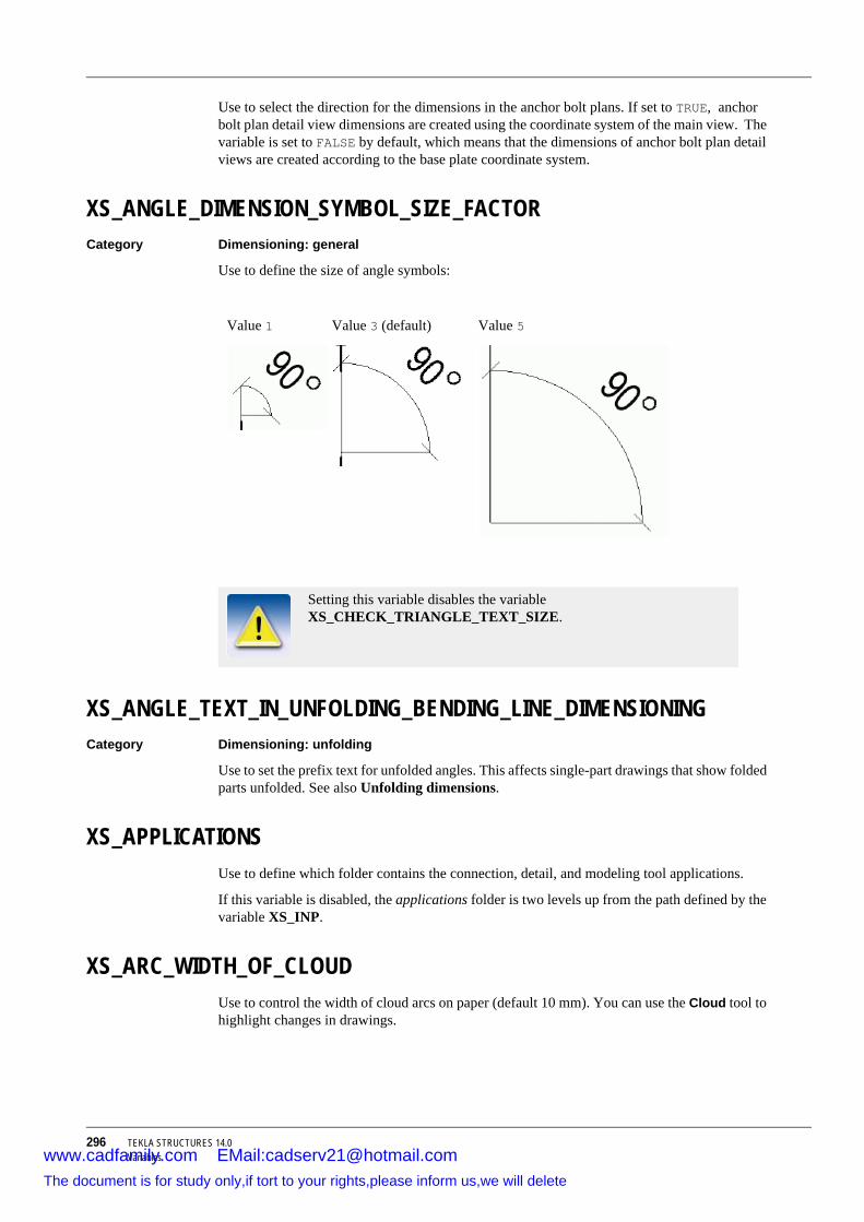
296 TEKLA STRUCTURES 14.0Variables
Use to select the direction for the dimensions in the anchor bolt plans. If set to TRUE, anchor bolt plan detail view dimensions are created using the coordinate system of the main view. The variable is set to FALSE by default, which means that the dimensions of anchor bolt plan detail views are created according to the base plate coordinate system.
XS_ANGLE_DIMENSION_SYMBOL_SIZE_FACTORCategory Dimensioning: general
Use to define the size of angle symbols:
XS_ANGLE_TEXT_IN_UNFOLDING_BENDING_LINE_DIMENSIONINGCategory Dimensioning: unfolding
Use to set the prefix text for unfolded angles. This affects single-part drawings that show folded parts unfolded. See also Unfolding dimensions.
XS_APPLICATIONSUse to define which folder contains the connection, detail, and modeling tool applications.
If this variable is disabled, the applications folder is two levels up from the path defined by the variable XS_INP.
XS_ARC_WIDTH_OF_CLOUDUse to control the width of cloud arcs on paper (default 10 mm). You can use the Cloud tool to highlight changes in drawings.
Value 1 Value 3 (default) Value 5
Setting this variable disables the variable XS_CHECK_TRIANGLE_TEXT_SIZE.
www.cadfamily.com EMail:[email protected] document is for study only,if tort to your rights,please inform us,we will delete

TEKLA STRUCTURES 14.0 297Variables
XS_ASCII_IMPORT_CREATES_CONSTRUCTION_LINESCategory Import
Set to 1 to have Tekla Structures only draw construction lines between object points in an ASCII import.
ASCII_LEGEND_PATHCategory Templates and symbols
Points to the location of the text fields listing file.
XS_ASSEMBLY_DRAWING_VIEW_TITLECategory Drawing properties
Use to define a title for assembly drawing views in a multi-drawing. The options are:
• PART_NAME
• PART_MATERIAL
• PART_POS, ASSEMBLY_POS
• MODEL_NUMBER
• LENGTH, PROFILE
• LENGTH
• BASE_NAME
• NAME
XS_ASSEMBLY_FAMILY_POSITION_NUMBER_FORMAT_STRINGCategory Numbering
Use to define the contents of the assembly family position number. For example, instead of DT1-1, DT1-2, you can define the numbering as DT1-1A or DT1-A, DT1-B.
Set the variable as follows:
XS_ASSEMBLY_FAMILY_POSITION_NUMBER_FORMAT_STRING= %%ASSEMBLY_PREFIX%%%%ASSEMBLY_FAMILY_NUMBER%-%%ASSEMBLY_FAMILY_QUALIFIER_WITH_LETTERS%%
Use the following switches to define the contents of family position numbers. Use as many switches as you need, and enclose each one in double percent symbols (%%).
Switch Description
%%ASSEMBLY_PREFIX%% Assembly prefix, defined in the part properties dialog box.
%%ASSEMBLY_FAMILY_NUMBER%% Assembly family number, defined by the start number (in part properties dialog box) and the final position in that numbering series.
www.cadfamily.com EMail:[email protected] document is for study only,if tort to your rights,please inform us,we will delete

298 TEKLA STRUCTURES 14.0Variables
See also Family numbering
XS_ASSEMBLY_MULTI_NUMBER_FORMAT_STRINGCategory Numbering
Use to base assembly numbers on drawing numbers. Use the following switches to define the contents of assembly marks. Use as many switches as you need, and enclose each one in double percent symbols (%%).
The available switches are:
Example To put the assembly multinumbers in the format multi drawing name + part prefix + position on multi drawing, set the variable as follows:
XS_ASSEMBLY_MULTI_NUMBER_FORMAT_STRING=%%ASSEMBLY_MULTI_DRAWING_NUMBER%%%%ASSEMBLY_PREFIX%%%%ASSEMBLY_MULTI_DRAWING_POS%%
This will create the assembly mark 10B1, where:
%%ASSEMBLY_FAMILY_POSITION_WITH_LETTERS%%
Assembly family letter, defined by the start character (in part properties dialog box) and the final character in the series.
Uses letters A to Z by default, but you can also define valid letters with the variable XS_VALID_CHARS_FOR_ASSEMBLY_FAMILY_POSITION_NUMBERS.
%%ASSEMBLY_FAMILY_QUALIFIER_WITH_LETTERS%%
Assembly family qualifier with letters.
Uses letters A – Z by default, but you can also define valid letters with the variable XS_VALID_CHARS_FOR_ASSEMBLY_FAMILY_QUALIFIER.
Switch Description
Switch Description
ASSEMBLY_MULTI_DRAWING_NUMBER
Multidrawing name.
ASSEMBLY_MULTI_DRAWING_POS
Position of the assembly drawing inside the multidrawing.
ASSEMBLY_PREFIX Assembly prefix in the model.ASSEMBLY_POS Assembly position number in the model.Template fields Enter UDA: followed by the name of any relevant
template field. Enclose each name in double percent symbols (%%). For example, %%UDA:PHASE%%
User-defined attributes Enter UDA: followed by the name of any relevant user-defined attribute, exactly as it appears in the objects.inp file. For example, %%UDA:MY_INFO_1%%
www.cadfamily.com EMail:[email protected] document is for study only,if tort to your rights,please inform us,we will delete

TEKLA STRUCTURES 14.0 299Variables
• 10 is the drawing number• B is the assembly prefix
• 1 designates that it is the first assembly on the sheet.
See also XS_PART_MULTI_NUMBER_FORMAT_STRING
XS_USE_MULTI_NUMBERING_FOR
XS_ASSEMBLY_POSITION_CODE_3DCategory Templates and symbols
Set to TRUE to include Z orientation in assembly position codes.
XS_ASSEMBLY_POSITION_CODE_TOLERANCECategory Templates and symbols
Tolerance distance to use when identifying grid position code for assembly.
XS_ASSEMBLY_POSITION_NUMBER_FORMAT_STRINGCategory Numbering
Use to have Tekla Structures only use letters in assembly numbers.
The switches are:
XS_ASSOCIATIVE_CHANGE_HIGHLIGHT_SIZECategory Dimensioning: General
Do not change this variable after you have created single-part, assembly, or cast-unit drawings! It may partially separate drawings from the part they are representing, causing the drawings to be flagged as deleted and another drawings cloned after the next numbering.
Switch Description
%%ASSEMBLY_PREFIX%% Assembly prefix, defined in the part properties dialog box.
%%ASSEMBLY_POS%% Assembly position number, defined by the start number (from part properties dialog box) and the final position in that numbering series.
%%ASSEMBLY_POS_WITH_LETTERS%%
Same as above, but with letters.
Uses letters A – Z by default, but you can also define valid letters with the variable XS_VALID_CHARS_FOR_ASSEMBLY_POSITION_NUMBERS.
www.cadfamily.com EMail:[email protected] document is for study only,if tort to your rights,please inform us,we will delete

300 TEKLA STRUCTURES 14.0Variables
Use to define the height of the change symbol around the points. The default value is 7.
See also XS_HIGHLIGHT_ASSOCIATIVE_DIMENSION_CHANGES (p. 346)
XS_ASSOCIATIVE_CHANGE_HIGHLIGHT_SYMBOLCategory Dimensioning: General
Use to define the used change symbol. The default value is AssociativityAnchor@1 (a cloud).
See also XS_HIGHLIGHT_ASSOCIATIVE_DIMENSION_CHANGES (p. 346)
XS_ATTRIBUTE_FILE_EXCLUDE_LIST Category File Locations
Enter the file name or a part of the file name that you want to exclude from the user interface as the value for the variable. If you enter many values, separate them using a semicolon (;). For example, setting the variable to _eng;_det removes all the attribute files that include the string _eng or _det in their name from the user interface.
XS_AUTOCONNECTION_TOLERANCECategory Components
Use to set the size of the area that Tekla Structures searches for parts to connect with AutoConnection. Can only be set in millimeters.
Example For 500 millimeters:
XS_AUTOCONNECTION_TOLERANCE=500.0
XS_AUTOCONNECTION_USE_UDLCategory Components
Set to switch on UDL calculation in AutoConnection. This calculates the maximum shear force allowed.
XS_AUTOCONNECTION_USE_UDL=TRUE
XS_AUTODEFAULT_UDL_PERCENTCategory Components
Use to set a default percentage for UDL calculation.
In AutoDefaultsTekla Structures uses the percentage in the connection properties. If no percentage is given, Tekla Structures uses this value.
In AutoConnection only the default percentage is used. You switch UDL calculation on with the variable XS_AUTOCONNECTION_USE_UDL.
XS_AUTODEFAULT_UDL_PERCENT=50
XS_AUTOMATIC_NEW_MODEL_NAMECategory Modeling Properties
www.cadfamily.com EMail:[email protected] document is for study only,if tort to your rights,please inform us,we will delete

TEKLA STRUCTURES 14.0 301Variables
Set to TRUE to have Tekla Structures suggest a name for a new model automatically in the New dialog box. The name of the model is New model XX, where XX is a running number.
Set the variable to FALSE to have no suggestion for a model name of a new model in the New dialog box. The variable is set to TRUE by default.
XS_AUTOMATIC_USER_FEEDBACK_SAVING_INTERVALCategory Modeling Properties
Use to change the saving interval of the automatic user feedback information. The value of the variable corresponds to the number of rows in the log file.
The log file is called UserFeedbackLog.txt and it is located in the TeklaStructuresModels folder.
XS_AUTOMATIC_USER_FEEDBACK_SENDING_INTERVALCategory Modeling Properties
Use to change the sending interval of the automatic user feedback information. The value of the variable corresponds to the number of rows in the log file.
The log file is called UserFeedbackLog.txt and it is located in the TeklaStructuresModels folder.
XS_AUTOSAVE_DIRECTORYCategory File locations
Use to point to the folder containing files Tekla Structures saves automatically.
If this variable is disabled, Tekla Structures places autosave files in the current model folder.
8.3 B
XS_BACKGROUND_COLOR1Category Model view
To have a gradient background color in model views, use the variables XS_BACKGROUND_COLOR1, XS_BACKGROUND_COLOR2, XS_BACKGROUND_COLOR3 and XS_BACKGROUND_COLOR4 to control the color of corners separately in a model view.
www.cadfamily.com EMail:[email protected] document is for study only,if tort to your rights,please inform us,we will delete

302 TEKLA STRUCTURES 14.0Variables
Define the color using the RGB (Red Green Blue) values (scale is from 0 to 1). If you want to use the traditional single-colored background, set the same value for all four background color variables. Reopen the view for the change to take effect.
Black or white background
• Use 0.0 0.0 0.0 for black background• Use 1.0 1.0 1.0 for white background
XS_BACKGROUND_COLOR2Category Model view
See XS_BACKGROUND_COLOR1.
XS_BACKGROUND_COLOR3Category Model view
See XS_BACKGROUND_COLOR1.
XS_BACKGROUND_COLOR4Category Model view
See XS_BACKGROUND_COLOR1.
XS_BASE_LINE_WIDTHCategory Plotting
www.cadfamily.com EMail:[email protected] document is for study only,if tort to your rights,please inform us,we will delete

TEKLA STRUCTURES 14.0 303Variables
Use to specify the base line width for printed drawings. The default value is 0.1. The final line thicknesses in a printed drawing is base line width multiplied by pen numbers from the Color table dialog box.
This variable also affects lines in the display, if XS_BASE_LINE_WIDTH_AFFECTS_SCREEN is set to TRUE.
XS_BASE_LINE_WIDTH_AFFECTS_SCREENCategory Plotting
Use to control whether XS_BASE_LINE_WIDTH affects line widths drawn in the display or not.
Enter FALSE in the Value field if you do not want XS_BASE_LINE_WIDTH to affect line widths in the display.
XS_BASICVIEW_HEIGHTCategory Model view
Use to control the height of basic view windows. For more information, see XS_BASICVIEW_POSITION_X.
Example XS_BASICVIEW_HEIGHT=570
XS_BASICVIEW_POSITION_XCategory Model view
Use to control the horizontal position of basic view windows on the screen.
Origin If the variable XS_MDIBASICVIEWPARENT is set, the origin for the position is the top left corner of the client area. Otherwise, the origin is the top left corner of the whole Tekla Structures window. Moving a toolbar also affects the size of the client area, because menus and toolbars are not part of it.
Units The width and height are in pixels.
XS_BASICVIEW_POSITION_YCategory Model view
Use to control the vertical position of basic view windows on the screen. For information on using this variable, see XS_BASICVIEW_POSITION_X.
XS_BASICVIEW_WIDTHCategory Model view
To control the accuracy of line thickness, use a small value for XS_BASE_LINE_WIDTH and a large number for the pen.
www.cadfamily.com EMail:[email protected] document is for study only,if tort to your rights,please inform us,we will delete

304 TEKLA STRUCTURES 14.0Variables
Use to control the width of basic view windows. For information on using this variable, see XS_BASICVIEW_POSITION_X.
XS_BEVEL_DIMENSIONS_FOR_PROFILES_ONLYCategory Dimensioning: Parts
Use to define whether to show bevel dimensions only for profiles.
By default, the variable is set to FALSE.
If yout set the variable to TRUE, bevel dimensions are shown only for profiles
If you set the variable to FALSE, bevel dimensions are shown always.
XSBINUse to define the location of the Tekla Structuresbin folder.
XS_BLACK_DRAWING_BACKGROUNDCategory Drawing view
Set to TRUE to have a black backgound and colored lines in drawings. To enable white background and black lines, clear the Value field.
See also Colors in drawings
XS_USE_COLOR_DRAWINGS
XS_BOLT_LENGTH_EPSILONCategory Modeling properties
Use to round bolt length.
Tekla Structures calculates bolt length using material thickness. To avoid having several bolt lengths where material thickness only differs slightly, set XS_BOLT_LENGTH_EPSILON to a positive or negative value. Tekla Structures adds or subtracts this value from the material thickness in bolt length calculation. Enter the value in millimeters (all environments). Typical values are 0.001–0.5.
See also Bolt length calculation
XS_BOLT_MARK_DIAMETER_PREFIXCategory Marking: bolts
Use to specify a prefix for bolt mark diameter. The possible values are NONE or the desired string.
Example For a bolt group consisting of three 20 mm diameter bolts:
This variable is user-specific, not model-specific. It only affects the colored mode, not black-and-white mode.
www.cadfamily.com EMail:[email protected] document is for study only,if tort to your rights,please inform us,we will delete

TEKLA STRUCTURES 14.0 305Variables
• If the variable is disabled
the result is 3*M20
• If XS_BOLT_MARK_DIAMETER_PREFIX=NONE
the result is 3*20
• If XS_BOLT_MARK_DIAMETER_PREFIX=D
the result is 3*D20
XS_BOLT_MARK_IS_ALWAYS_VISIBLE_IN_GACategory Marking: bolts
Set to TRUE to hide the bolt marks of bolts hidden from views by other objects in general arrangement drawings.
Example If there are bolts on either side of a beam, one will be hidden by the beam in front of it. Set this variable to TRUE to prevent Tekla Structures displaying the bolt mark of the hidden bolt.
XS_BOLT_MARK_STRING_FOR_SIZECategory Marking: bolts
Use to define the contents of the Size element in bolt marks. The variables XS_SHOP_BOLT_MARK_STRING_FOR_SIZE and XS_SITE_BOLT_MARK_STRING_FOR_SIZE override this setting.
For switches you can use to define the contents, see Size element in bolt marks.
XS_BOLT_MARK_STRING_FOR_SIZE_IN_GACategory Marking: Bolts
Use to define the contents of the size element in bolt marks in general arrangement drawings. If you have not set the variables XS_SHOP_BOLT_MARK_STRING_FOR_SIZE_IN_GA (p. 385) or XS_SITE_BOLT_MARK_STRING_FOR_SIZE_IN_GA (p. 391), then this variable is used.
See also Size element in bolt marks
XS_BOLT_POSITION_TO_MIN_AND_MAX_POINTCategory Dimensioning: bolts
Use to create minimum and maximum position dimensions for bolts.
Example XS_BOLT_POSITION_TO_MIN_AND_MAX_POINT=TRUE
XS_BOLTS_PERPENDICULAR_TO_PART_PLANE_IN_NCCategory CNC
Set to TRUE to dimension bolts perpendicular to part plane in NC files.
www.cadfamily.com EMail:[email protected] document is for study only,if tort to your rights,please inform us,we will delete

306 TEKLA STRUCTURES 14.0Variables
8.4 C
XS_CALC_REFOBJ_PROTECTSet toTRUE to have Tekla Structures calculate the protection area of reference objects in drawings. By default Tekla Structures does not calculate the protection area.
XS_CALCULATE_POLYBEAM_LENGTH_ALONG_REFERENCE_LINECategory Dimensioning: unfolding
Use to have Tekla Structures calculate polybeam length along the reference line instead of the centerline. By default, Tekla Structures measures polybeam length along the centerline of the beam, regardless of the Position in plane values of the beam.
See also Polybeam length calculation.
XS_CENTER_TO_CENTER_DISTANCE_IN_ONE_PART_STRINGCategory Marking: bolts
Use to define gage information in the bolt mark. See also GOL, C/C, GAGE.
Defining the contents
Use the switch %%VALUE%% for the numeric value of a gage. Add text before and after the value.
If %%VALUE%% is missing, then Tekla Structures adds the center-to-center distance to the end of the string.
If the variable is disabled, only %%VALUE%% is used.
If Tekla Structures cannot calculate the gage, then nothing is added to the mark.
Example There is a symmetrical bolt group in beam flange. The value for gage is 10.
There should not be any reason to set this variable, as the protect informa-tion for reference objects is currently not used in drawing creation. Using this variable slows down drawing production.
The centerline option is always a safe alternative, because other modifi-cations do not impact on it. For example, if you calculate length using the reference line and you have used offsets to move the beam, the result may not be the true length of the beam.
Definition in the initialization file Bolt mark
set XS_CENTER_TO_CENTER_DISTANCE_IN_ONE_PART_STRING=GAGE = %%VALUE%%
GAGE = 10
www.cadfamily.com EMail:[email protected] document is for study only,if tort to your rights,please inform us,we will delete

TEKLA STRUCTURES 14.0 307Variables
XS_CENTER_TO_CENTER_DISTANCE_IN_TWO_PARTS_STRINGCategory Marking: bolts
Use to define the center-to-center distance information in the bolt mark where there are two parts.
For more information on defining the contents, see XS_CENTER_TO_CENTER_DISTANCE_IN_ONE_PART_STRING.
Example For a symmetrical bolt group in two clip angles. The center-to-center distance is 10.
XS_CHAMFER_ACCURACY_FACTORCategory Speed and accuracy
Use to define the number of points used for chamfers.
The default value is 1.0. Use values smaller than 1.0 to increase the number of points. Use values larger than 1.0 to decrease the number of points.
XS_CHAMFER_DISPLAY_LENGTH_FACTORCategory Model view
Use to adjust chamfer length. Tekla Structures calculates plate chamfer length from the plate side length using the following formula: XS_CHAMFER_DISPLAY_LENGTH_FACTOR * plate side length. By default this factor is 0.08.
XS_CHANGE_DRAGGED_DIMENSIONS_TO_FIXEDCategory Drawing Properties
Use to define whether dimensions have fixed placing when you drag them away from their original locations. When set to TRUE, dimension placing uses fixed placing routine instead of free placing.
XS_CHANGE_DRAGGED_MARKS_TO_FIXEDCategory Drawing Properties
Use to define whether part, bolt and reinforcement marks have fixed placing when you drag them away from their original locations. When set to TRUE, mark placing uses fixed placing routine instead of free placing.
XS_CHANGE_DRAGGED_NOTES_TO_FIXEDCategory Drawing Properties
Definition in the initialization file Bolt mark
set XS_CENTER_TO_CENTER_DISTANCE_IN_TWO_PARTS_STRING=c/c = %%VALUE%%
c/c = 10
www.cadfamily.com EMail:[email protected] document is for study only,if tort to your rights,please inform us,we will delete

308 TEKLA STRUCTURES 14.0Variables
Use to define whether associative notes have fixed placing when you drag them away from their original locations. When set to TRUE, associative notes placing uses fixed placing routine instead of free placing.
XS_CHANGE_DRAGGED_TEXTS_TO_FIXEDCategory Drawing Properties
Use to define whether texts have fixed placing when you drag them away from their original locations. When set to TRUE, text uses fixed placing routine instead of free placing.
XS_CHANGE_DRAGGED_VIEWS_TO_FIXEDCategory Drawing Properties
Use to define whether views have fixed placing when you drag them away from their original locations. When set to TRUE, view placing uses fixed placing routine instead of free placing
XS_CHANGE_MARK_ASTERISK_TOCategory Marking: parts
Use to specify a symbol to replace the asterisk character (*) in bolt marks and the size elements of part marks.
Example XS_CHANGE_MARK_ASTERISK_TO=X
You cannot use this variable to change the asterisk character in profile strings (e.g. PL10*100).
XS_CHANGE_WORKAREA_WHEN_MODIFYING_VIEW_DEPTHCategory Model view
Makes working with reference files easier. By default, objects such as parts and reference files outside the work area are not visible, even when they are within the display depth range.
Set to TRUE to automatically adjust the work area when you change the display depth.
XS_CHECK_FLAT_LENGTH_ALSOCategory Plate work
Set to TRUE to have Tekla Structures check plate length and plate width, then compare it with the possible dimensions for flat bars in fltprops.inp.
If disabled, Tekla Structures only checks plate width.
XS_CHECK_TRIANGLE_TEXT_SIZECategory Dimensioning: general
Sizes the triangle to fit text in bevel dimensions.
www.cadfamily.com EMail:[email protected] document is for study only,if tort to your rights,please inform us,we will delete

TEKLA STRUCTURES 14.0 309Variables
To define the angle symbol size, use the variable XS_ANGLE_DIMENSION_SYMBOL_SIZE_FACTOR.
XS_CHORD_TOLERANCE_FOR_SMALL_TUBE_SEGMENTSCategory Speed and Accuracy
Use to define the chord tolerance for round tubes smaller than or equal to the limit set by the variable XS_CHORD_TOLERANCE_SMALL_TUBE_SIZE_LIMIT. Enter the value in millimeters. The default value is 1.0.
See also XS_CHORD_TOLERANCE_SMALL_TUBE_SIZE_LIMIT (p. 310)
XS_CHORD_TOLERANCE_FOR_TUBE_SEGMENTS (p. 309)
XS_CHORD_TOLERANCE_FOR_TUBE_SEGMENTSCategory Speed and Accuracy
Use to define the chord tolerance for round tubes larger than the limit set by the variable XS_CHORD_TOLERANCE_SMALL_TUBE_SIZE_LIMIT. Enter the value in millimeters. The default value is 1.0.
Chord tolerance Chord tolerance is the maximum difference between a straight segment used to display a tubular section in model views and the actual tubular section:
Using variable XS_ANGLE_DIMENSION_SYMBOL_SIZE_FACTOR will disable variable XS_CHECK_TRIANGLE_TEXT_SIZE.
www.cadfamily.com EMail:[email protected] document is for study only,if tort to your rights,please inform us,we will delete

310 TEKLA STRUCTURES 14.0Variables
See also XS_CHORD_TOLERANCE_SMALL_TUBE_SIZE_LIMIT (p. 310)
XS_CHORD_TOLERANCE_FOR_SMALL_TUBE_SEGMENTS (p. 309)
XS_CHORD_TOLERANCE_SMALL_TUBE_SIZE_LIMITCategory Speed and Accuracy
Use to define the limit that determines whether a tube is considered small when calculating the chord tolerance. The value is compared to the diameter of the profile. Enter the value in millimeters. The default value is 50.0.
See also XS_CHORD_TOLERANCE_FOR_TUBE_SEGMENTS (p. 309)
XS_CHORD_TOLERANCE_FOR_SMALL_TUBE_SEGMENTS (p. 309)
XS_CIS_DEP1_DATABASE_NAMEUse to define the name of the temporary database used in CIMsteel transfers.
XS_CIS_DEP1_DATABASE_PASSWUse to define the password for the temporary database used in CIMsteel transfers.
XS_CIS_DEP1_DATABASE_PATHUse to define a path to the temporary database that Tekla Structures creates while converting a model from/to CIMsteel STEP format.
XS_CIS_DEP1_EXPRESS_FILEUse to define the name of the EXPRESS file located in the system folder. The EXPRESS file describes the CIMsteel DEP1 logical product model. It is used when you convert a Tekla Structures model to/from CIMsteel DEP1 STEP format.
XS_CLASH_CHECK_BETWEEN_REFERENCESCategory Modeling Properties
Use to define whether or not Tekla Structures should run the clash check also between reference models.
www.cadfamily.com EMail:[email protected] document is for study only,if tort to your rights,please inform us,we will delete

TEKLA STRUCTURES 14.0 311Variables
Set to TRUE if you want to perform clash check also between two reference models. The default value is FALSE.
XS_CLASH_CHECK_COLORCategory Model view
Use to change the color that indicates clashing parts. You can use fourteen colors (numbered from 1 to 14, see Colors). The default color is yellow (= 6).
XS_CLEAR_MODEL_HISTORYCategory Speed and accuracy
If you use model history log files, set this variable to clear history data from the log file each time you open and save the model.
See also XS_COLLECT_MODEL_HISTORY
XS_CNC_HOLE_DIAMETER_ROUNDINGCategory CNC
Defines the rounding factor of holes for NC files. NC files are accurate to 0.01 mm.
Use to round up bolt diameters with very small differences in diameter to the same value. You may need to use different diameters because bolts can have different tolerance values in a Tekla Structures model. You can input more decimals into bolt tolerance values in the component dialog boxes than in the general bolt dialog box.
The rounding routine is used only when you create NC files.
Set the rounding factor the same value (in mm) as the drill tolerance of the machine tool.
Tekla Structures divides the original hole diameter by the rounding factor, then rounds the result to the nearest integer, then multiplies it by the rounding factor. As a result, bolt diameters with very small differences in diameter are now rounded up to the same value.
Example set XS_CNC_HOLE_DIAMETER_ROUNDING=1.5875
Here the rounding factor is 1.5875 (1/16 inch), which results in:
• Diameter 26.99 mm (1” 1/16 from component dialog box) => 26.99/1.5875 => 17.00 => 17 => 17*1.5875 => 26.99 mm
• Diameter 27.00 mm (1” 1/16 from bolt dialog box) => 27.00/1.5875 => 17.01 => 17 => 17*1.5875 => 26.99 mm
XS_COLLECT_MODEL_HISTORYCategory Speed and accuracy
Tekla Structures can collect model history data on various objects, for example, parts in the inquire object dialog, rebars, components in reports, etc. Collecting model history data may require a lot of disk space and memory so Tekla Structures does not collect it by default. To collect the data, set this variable to TRUE.
We recommend that you collect the history only if you really need it.
www.cadfamily.com EMail:[email protected] document is for study only,if tort to your rights,please inform us,we will delete

312 TEKLA STRUCTURES 14.0Variables
See also XS_CLEAR_MODEL_HISTORY
XS_COMBINED_BOLT_DIM_CHARACTERCategory Dimensioning: bolts
Use to set the character in bolt dimensions.
Example The character used in the bolt dimension 4*50 is *.
XS_COMPLEX_PART_MEMBERS_DO_NOT_HAVE_TO_BE_MAIN_PARTSCategory Dimensioning: parts
Use in complex part/ assembly dimensioning to have Tekla Structures dimension other than main parts as one.
XS_COMPONENT_CATALOG_COLLECTION_NAME_LENGTHCategory Modeling properties
Collection names in the component catalog are truncated to 12 characters. Use this variable to adjust the length of the names, then re-open the component catalog.
See also XS_COMPONENT_CATALOG_THUMBNAIL_SIZE
XS_COMPONENT_CATALOG_THUMBNAIL_SIZECategory Modeling properties
Use to adjust the size of thumbnails to between 6 and 96 pixels. The default is 96 pixels. After changing the value, re-open the component catalog.
See also XS_COMPONENT_CATALOG_COLLECTION_NAME_LENGTH
This variable works mainly in multi-user mode. In single-user mode Tekla Structures collects the history data only on deleted parts.
This may increase the size of the component catalog dialog box.
This may increase the size of the component catalog dialog box.
www.cadfamily.com EMail:[email protected] document is for study only,if tort to your rights,please inform us,we will delete

TEKLA STRUCTURES 14.0 313Variables
XS_CONCRETE_PART_NUMBERING_PREFIXUse to define a numbering prefix for concrete parts.
XS_CONCRETE_PART_NUMBERING_START_NUMBERUse to define a starting number for concrete parts.
XS_CONNECTING_SIDE_MARK_SYMBOLCategory Marking: parts
Use to change the symbol for a connecting side mark. By default the side mark symbol is number 34 in the symbol file. To change the symbol, set this variable to a different symbol number.
XS_CONNECT_PLATE_PROFILES_IN_AUTOCONNECTIONCategory Components
Set to TRUE to enable AutoConnection for built-in members. If disabled, Tekla Structures does not consider plates as members when you use AutoConnection.
XS_CONSIDER_NEIGHBOUR_PARTS_IN_HIDDENCategory Drawing properties
Set to draw parts behind neighboring parts using hidden lines.
XS_CONSIDER_REBAR_NAME_IN_NUMBERINGCategory Concrete detailing
Set to FALSE to haveTekla Structures only take part names into account when numbering, not reinforcing bar names.
XS_CONVERT_OLD_FORCE_UNITS_TO_SI_FROMCategory Components
Use to define how to convert part and connection attribute tables when you open a Tekla Structures catalog prior to version 7.0.
Example To convert force units from kip to SI, set XS_CONVERT_OLD_FORCE_UNITS_TO_SI_FROM to kip.
You can use the following units: kg/T/N/daN/kN/lbf/kip, or a numerical value.
XS_CONVERT_OLD_MOMENT_UNITS_TO_SI_FROMUse to define how to convert part and connection attribute tables when you open a Tekla Structures catalog prior to version 7.0.
Example To convert moment units from kip-ft to SI, set XS_CONVERT_OLD_MOMENT_UNITS_TO_SI_FROM to kip-ft.
www.cadfamily.com EMail:[email protected] document is for study only,if tort to your rights,please inform us,we will delete

314 TEKLA STRUCTURES 14.0Variables
You can use the following units: kgm/Tm/Nm/daNm/kNm/lbf-in/lbf-ft/kip-in/kip-ft, or a numerical value.
XS_COUNT_ALL_PARTS_IN_NSFS_REPEATED_PART_MARKCategory Marking: parts
Use to determine how the quantity of parts with merged part marks is shown.
Example When there are four or more identical stiffeners on both sides of a beam web, the mark is
• 4x1002BS if XS_COUNT_ALL_PARTS_IN_NSFS_REPEATED_PART_MARK=TRUE• 2x1002BS if XS_COUNT_ALL_PARTS_IN_NSFS_REPEATED_PART_MARK is not set.
See also XS_COUNT_BOTH_PARTS_IN_NSFS_PART_MARK
XS_COUNT_BOTH_PARTS_IN_NSFS_PART_MARKCategory Marking: parts
Use to determine how the quantity of parts with merged part marks is shown.
Example When there are two identical stiffeners on both sides of a beam web, the mark is
• 2x1002BS if XS_COUNT_BOTH_PARTS_IN_NSFS_PART_MARK=TRUE• 1002BS if XS_COUNT_BOTH_PARTS_IN_NSFS_PART_MARK is not set.
See also XS_COUNT_ALL_PARTS_IN_NSFS_REPEATED_PART_MARK
XS_CREATE_MISSING_MARKS_IN_INTELLIGENT_CLONINGCategory Marking: General
Use to create all marks to a cloned drawing where new parts have been added, set the variable
To create the marks, set the variable to TRUE. The default is FALSE.
XS_CREATE_ROUND_HOLE_DIMENSIONSCategory Dimensioning: parts
Enter TRUE in the Value field to have Tekla Structures dimension the round hole center point in drawings.
XS_CREATE_CONNECTION_WHEN_COPYING_DRAWING_VIEWSCategory Drawing properties
Set to TRUE to link copied views to the original drawing. For example, when you delete a drawing from which you copied a view, Tekla Structures also deletes the copied view.
XS_CREATE_VIEW_FROM_MODEL_OLD_WAYUse to specify which values Tekla Structures uses for view extrema in general arrangement drawings. This only affects views created from the model.
If disabled (default), the view extrema values are based on the current work area x and y coordinates of a model view.
www.cadfamily.com EMail:[email protected] document is for study only,if tort to your rights,please inform us,we will delete

TEKLA STRUCTURES 14.0 315Variables
When this variable is set to TRUE, the extrema values of a drawing view are based on the entire model view, ignoring the work area settings.
In both cases depth values are based on the model view display depth values.
XS_CS_CHAMFER_DIVIDE_ANGLECategory Speed and accuracy
Use to change the angles dividing a cross section chamfer (default 10.0 degrees).
Example XS_CS_CHAMFER_DIVIDE_ANGLE=10.0
XS_CURVED_AXIS_PLACECategory Profiles
By default, Tekla Structures calculates the length of curved parts along the center axis. Use this variable to define the position of this axis as a ratio.
Tekla Structures calculates the location of the axis using the formula h=H/2.0*ratio. The default value is zero. Define the ratio as 1.0 to calculate length along the upper flange. Define the ratio as -1.0 to define the length along the lower flange.
This value is used in reports and drawing templates.
XS_CUT_SYMBOL_FONTUse to define the font for section symbol text. If you do not specify a font, Tekla Structures uses the default font.
XS_CYCLIC_SOLVER_MAX_LOOPSCategory Modeling properties
Use to define how many cycles Tekla Structures makes to solve the dependencies in custom components. Enter a number for the amount of cycle loops. The default is 2.
XS_CYCLIC_SOLVER_USE_ATTRIBUTE_LOOPSCategory Modeling properties
Used in solving dependencies in custom components. Attributes should not be used when Tekla Structures is solving the multiple dependencies so set this variable to FALSE.
See also XS_CYCLIC_SOLVER_MAX_LOOPS
8.5 D
DAK_BMPPATHUse to point to the folder for bitmap files used in
• custom components
www.cadfamily.com EMail:[email protected] document is for study only,if tort to your rights,please inform us,we will delete

316 TEKLA STRUCTURES 14.0Variables
• user-defined attributes (objects.inp file)
• profile catalog
• some system components
By default this variable is defined in the teklastructures.ini file and it points to the folder:\TeklaStructures\14.0\nt\bitmaps
To change this folder
1. Copy the entire contents of the \TeklaStructures\14.0\nt\bitmaps folder to the new location.
2. Add this variable DAK_BMPPATH to the user.ini file.
XS_DEFAULT_FONTCategory Model view
Use to specify the default font when modeling and drawing.
XS_DEFAULT_FONT_SIZECategory Model view
Use to set the default font size when modeling.
XS_DELETE_UNNECESSARY_DRAWINGSCategory This variable is available only in initialization files.
Set the variable to TRUE in the global_default_env.ini file located in the ..\TeklaStructures\14.0\environments\country-independent folder to have Tekla Structures delete unnecessary drawing files.
See also Deleting unnecessary dg files (p. 75)
XS_DETAIL_BOUNDARY_RADIUSCategory Drawing Properties
Use to define a fixed size for circle-shaped detail boundaries in detail views.
Enter a numeric value in millimeters for the radius.
XS_DETAIL_SYMBOL_REFERENCECategory Drawing properties
Sets the reference text for symbols that show a detail from another drawing. Enter the text in the Value field. The text can include:
• free text• user-defined attributes
• template attributes
If you set the variable in the Advanced options dialog box, use single % characters around the user-defined and template attributes. For example, %DRAWING_TITLE%.
www.cadfamily.com EMail:[email protected] document is for study only,if tort to your rights,please inform us,we will delete
TEKLA STRUCTURES 14.0 317Variables
If you set the variable in the initialization files, use double % characters around the user-defined and template attributes. For example, %%DRAWING_TITLE%%.
XS_DETAIL_VIEW_REFERENCECategory Drawing properties
Sets the reference text for detail view labels. See also XS_DETAIL_SYMBOL_REFERENCE.
XS_DGN_EXPORT_PART_ASCategory Export
Use to specify how Tekla Structures exports solids to DGN format.
Set to CELL to export solids as cells containing the solid faces as a DGN shape.
Set to SOLID to export solids as DGN solids defined by boundary elements.
XS_DGN_EXPORT_USE_LOCAL_IDCategory Export
Enter TRUE in the Value field to enable the use of local ID numbers in 3D DGN export. Every exported part gets a unique ID number starting from 1. The ID is saved as a user-defined attribute and the same ID will be used in consequent exports.
XS_DIMENSION_ALL_BOLT_GROUPS_SEPARATELYCategory Dimensioning: bolts
Se to TRUE to prevent Tekla Structures from combining bolt group dimensions.
XS_DIMENSION_DECIMAL_SEPARATORCategory Dimensioning: General
Use to define the character to be used as a decimal separator in dimension and level marks.
XS_DIMENSION_DECIMAL_SEPARATOR = <separator character>.
In the following example, the dimension mark contains a comma when the dimension settings in the Dimension Properties dialog box are as follows, and the variable is set to XS_DIMENSION_DECIMAL_SEPARATOR=,
www.cadfamily.com EMail:[email protected] document is for study only,if tort to your rights,please inform us,we will delete

318 TEKLA STRUCTURES 14.0Variables
In the following example, the separator was first a period and was then changed to a comma.
XS_DIMENSION_DIGIT_GROUPING_CHARACTERCategory Dimensioning: general
Use to specify which separator character to use in large dimension values: for example a comma (,), where 154321 would become 154,321. If no character is specified, Tekla Structures uses a space in dimensions when you select Yes in Dimension properties > General > Use grouping.
See also XS_DIMENSION_DIGIT_GROUPING_COUNT
Dimension properties
XS_DIMENSION_DIGIT_GROUPING_COUNTCategory Dimensioning: general
Use to specify the number of digits after which a separator character will be inserted in dimension values: for example 3, where 154321 would become 154 321.
See also XS_DIMENSION_DIGIT_GROUPING_CHARACTER
Dimension properties
www.cadfamily.com EMail:[email protected] document is for study only,if tort to your rights,please inform us,we will delete

TEKLA STRUCTURES 14.0 319Variables
XS_DIMENSION_EXTENSION_LINE_AWAY_FACTORCategory Dimensioning: general
See Create short extension lines.
XS_DIMENSION_EXTENSION_LINE_ORIGIN_OFFSETCategory Dimensioning: general
Use to specify the distance between the extension line origin and the start of the extension line (extension origin offset).
XS_DIMENSION_EXTENSION_LINE_ORIGIN_OFFSET=1.0
XS_DIMENSION_EXTENSION_LINE_TOWARD_FACTORCategory Dimensioning: general
See Create short extension lines.
XS_DIMENSION_FONTUse to specify the font for dimension text. If you do not specify a font, Tekla Structures uses the default font.
XS_DIMENSION_LINE_TEXT_EPSCategory Dimensioning: parts
Flips dimension text that is sloped more than the given value. For more information, see Aligning sloped dimension text.
Example XS_DIMENSION_LINE_TEXT_EPS=0.1
XS_DIMENSION_PART_MARK_CONTENT_IN_ASSEMBLYCategory Dimensioning: parts
Use to define the content of the part mark dimension in assembly drawings.
The available switches are:
• PROFILE
• MATERIAL
• SIZE
extension origin offset
www.cadfamily.com EMail:[email protected] document is for study only,if tort to your rights,please inform us,we will delete

320 TEKLA STRUCTURES 14.0Variables
• LENGTH
• COMMENT
• WPDIST (distance between work points)
• GR_L (gross length of the part)
Example XS_DIMENSION_PART_MARK_CONTENT_IN_ASSEMBLY=PROFILE_AND_MATERIAL
XS_DIMENSION_PART_MARK_CONTENT_IN_ASSEMBLY=PROFILE_AND_GR_L
See XS_DIMENSION_PART_MARK_CONTENT_IN_SINGLE.
XS_DIMENSION_PART_MARK_CONTENT_IN_SINGLECategory Dimensioning: Parts
Use to define the content of the part mark dimension in single part drawings.
Example XS_DIMENSION_PART_MARK_CONTENT_IN_SINGLE=PROFILE_AND_MATERIAL
XS_DIMENSION_PART_MARK_CONTENT_IN_SINGLE=PROFILE_AND_GR_L
The available switches are:
• PROFILE
• MATERIAL
• SIZE
• LENGTH
• COMMENT
• WPDIST (distance between work points)
• GR_L (gross length of the part)
XS_DIMENSION_PLATE_SIDE_MARK_SYMBOL_CENTERCategory Dimensioning: general
To define the symbol Tekla Structures uses in plate side marks, use the following variables:
• XS_DIMENSION_PLATE_SIDE_MARK_SYMBOL_LEFT
• XS_DIMENSION_PLATE_SIDE_MARK_SYMBOL_CENTER
• XS_DIMENSION_PLATE_SIDE_MARK_SYMBOL_RIGHT
By default Tekla Structures uses the symbols no 0, 1 and 2 , defined in the dim ension_marks.sym file (located usually in the folder \environments\country-independent\symbols\).
XS_DIMENSION_PLATE_SIDE_MARK_SYMBOL_LEFTCategory Dimensioning: general
See XS_DIMENSION_PLATE_SIDE_MARK_SYMBOL_CENTER
www.cadfamily.com EMail:[email protected] document is for study only,if tort to your rights,please inform us,we will delete

TEKLA STRUCTURES 14.0 321Variables
XS_DIMENSION_PLATE_SIDE_MARK_SYMBOL_RIGHTCategory Dimensioning: general
See XS_DIMENSION_PLATE_SIDE_MARK_SYMBOL_CENTER
XS_DIMENSION_POINT_CIRCLE_COLORCategory Dimensioning: General
Use to define the color of the dimension point invalidity symbol circles. Enter a numerical value or the name of the color. Default is DARK RED.
Other valid color names are RED, DARK RED, GREEN, DARK GREEN, BLUE, DARK BLUE, CYAN, DARK CYAN, GREY, DARK GREY, DARK YELLOW, ORANGE, MAGENTA, BLACK.
XS_DIMENSION_POINT_CIRCLE_INNER_RADIUSCategory Dimensioning: General
Use to define the length of the inner radius of the dimension point circle. Tekla Structures marks the invalid dimensions with red dimension point circles.
Enter a decimal value for the custom size of the radius. The default value is 1.0.
See also XS_DIMENSION_POINT_CIRCLE_OUTER_RADIUS (p. 321)
XS_DIMENSION_POINT_CIRCLE_OUTER_RADIUSCategory Dimensioning: General
Use to define the length of the outer radius of the dimension point circle. Tekla Structures marks the invalid dimensions with red dimension point circles.
Enter a decimal value for the custom size of the radius. The default value is 6.0.
See also XS_DIMENSION_POINT_CIRCLE_INNER_RADIUS (p. 321)
XS_DIMENSION_SKEWED_BOLTS_IN_PART_PLANE_IN_SINGLE_DRAWINGSCategory Dimensioning: bolts
Set to TRUE to dimension bolts perpendicular to the part plane in single-part drawings.
XS_DIRUse to point to the folder for Tekla Structures data, source, and binary files.
XS_DISABLE_ADVANCED_OPTIONSYou can disable the Advanced options dialog box so that the variables can be edited in the batch files only.
To disable the dialog box, set this variable in the initialization files:
set XS_DISABLE_ADVANCED_OPTIONS=TRUE
www.cadfamily.com EMail:[email protected] document is for study only,if tort to your rights,please inform us,we will delete

322 TEKLA STRUCTURES 14.0Variables
For more information on variables, seeSetting variables (p. 80).
XS_DISABLE_CANCEL_DIALOG_FOR_SAVE_NUMBERING_SAVECategory Numbering
Use to revert to the old numbering functionality that offers no option to cancel numbering before the second save is made.
See also Numbering setup
XS_DISABLE_CIS2Category Analysis & Design
Use to hide or display the CIMSteel command.
To hide the CIMSteel command in the File > Export and File > Import menus, set the XS_DISABLE_CIS2 variable to TRUE.
Restart Tekla Structures for the change to take effect.
XS_DISABLE_CLASSIFIER_FOR_MODIFIED_PARTSCategory Drawing Properties
Use to disable the Drawing Classifier check for modified parts. When you change part properties in a model after you have defined the Drawing Classifier settings, part presentation and mark content are updated in general arrangement drawings unless you have set this variable to TRUE.
To disable the check for modified parts, set the variable to TRUE.
To enable the check for modified parts, set the variable to FALSE.
Drawings are not updated if the change does not affect numbering.
XS_DISABLE_DRAWING_PLOT_DATECategory Drawing Properties
Use to disable the print date information in drawings. Disabling the print date helps to avoid possible conflicts when working with multi-user models in situations where a user modifies drawings while another user prints the same drawings.
By default, the variable is set to TRUE.
XS_DISABLE_PARTIAL_REFRESHCategory Drawing view
Set to TRUE to disable partial refreshing of OpenGL windows.
XS_DISABLE_TEMPLATE_DOUBLE_CLICKCategory Drawing Properties
Use to define whether templates are opened when you double-click the template table in drawings.
www.cadfamily.com EMail:[email protected] document is for study only,if tort to your rights,please inform us,we will delete

TEKLA STRUCTURES 14.0 323Variables
By default, the variable is set to FALSE.
When set to FALSE, the default template editor will be opened when you double-click the template table.
When set to TRUE, the Drawing Properties dialog is shown when you double-click the template table.
XS_DISABLE_VIEW_CENTERING_ASSEMBLYCategory Drawing view
Use to left-align assembly drawing views.
XS_DISABLE_VIEW_CENTERING_GACategory Drawing view
Use to left-align GA drawing views.
XS_DISABLE_VIEW_CENTERING_MULTICategory Drawing view
Use to left-align multi drawing views.
XS_DISABLE_VIEW_CENTERING_SINGLECategory Drawing view
Use to left-align single-part drawing views.
XS_DISABLE_WELD_PREP_SOLIDUse to disable automatic weld preparation. Set this variable to TRUE to prevent automatic weld preparation when using certain weld types.
XS_DISPLAY_ZERO_INCHESCategory Imperial units
Use to display zero inches.
XS_DISTANT_OBJECT_FINDER_TOLERANCECategory Model View
Use to define the distance outside of which the object must be located for it to be listed by the Find Distant Objects tool.
The distance is measured from the nearest part. Enter the value in meters. The default value is 100.
See also Finding distant objects
www.cadfamily.com EMail:[email protected] document is for study only,if tort to your rights,please inform us,we will delete

324 TEKLA STRUCTURES 14.0Variables
XS_DO_NOT_CHECK_DIMENSION_POINTSCategory Dimensioning: general
Set to TRUE to prevent Tekla Structures from checking dimension points when you open drawings.
Or define settings for different drawing types using any combination of the switches A, W, M, G and C (assembly, single-part, multi-, general arrangement and cast unit drawings).
Example To apply to general arrangement, multi- and assembly drawings, set to GMA.
XS_DO_NOT_CREATE_ASSEMBLY_DRAWINGS_FOR_CONCRETE_PARTSCategory Drawing Properties
Use to control the creation of single-part and assembly drawings from concrete parts.
To enable the creation of drawings, set the variable to FALSE.
To disable the creation of drawings, set the variable to TRUE.
XS_DO_NOT_CREATE_PROFILE_DIMENSIONS_FOR_CONCRETESet to TRUE to prevent Tekla Structures from automatically displaying the profile dimensions of concrete parts in cast-unit drawings.
XS_DO_NOT_DISPLAY_CHAMFERSCategory Model view
Set to TRUE to draw polygon plates without chamfers.
XS_DO_NOT_DRAW_COLUMN_MARKS_AT_45_DEGREES_IN_GA_DRAWINGCategory Marking: parts
Tekla Structures places column marks in GA drawing plan views by default at an angle of 45 degrees in respect to the position of the column. To place the marks horizontally, set this variable to TRUE.
XS_DO_NOT_EXTEND_DIMENSION_LINES_THROUGH_ALL_HOLESCategory Dimensioning: bolts
Set to TRUE to prevent leader lines from extending through all holes in a bolt group.
Using this variable in drawings that contain a lot of parts, especially curved ones, slows down opening drawings and uses a lot of memory.
www.cadfamily.com EMail:[email protected] document is for study only,if tort to your rights,please inform us,we will delete

TEKLA STRUCTURES 14.0 325Variables
XS_DO_NOT_PLOT_DIMENSION_POINT_CIRCLESCategory Dimensioning: general
Set to TRUE to prevent Tekla Structures from printing red dimension point circles when you print from the drawing list. Red dimension point circles are always printed, if you have the Drawing Editor open.
XS_DO_NOT_REMOVE_END_ABSOLUTE_DIMENSIONSCategory Dimensioning: parts
When you use absolute dimensions, by default, Tekla Structures removes the last absolute vertical dimension. To prevent this, set to TRUE.
XS_DO_NOT_USE_DMPAPER_USERTekla Structures uses a predefined value DMPAPER_USER as the user-defined paper size when printing. Set this to TRUE to enable the old paper size definition .
set XS_DO_NOT_USE_DMPAPER_USER=TRUE
XS_DO_NOT_USE_FOLDED_GUSSET_PLATESet to use part-adds to create folded plates in gusset connections. If disabled (default), Tekla Structures creates folded gusset plates using the Polybeam command instead of the Part-add command.
XS_DO_NOT_USE_GLOBAL_PLATE_SIDECategory Components
By default, connections 141, 146, 147, 149, 181, 184, 185, 186 and 187 create all shear plates on the same side of the main part, if the main part has several connections (global positioning). Use this variable to position each shear plate according to which end of the main part the connection that creates it is closest to (local positioning).
XS_DONT_SHOW_POLYBEAM_MID_EDGESCategory Drawing properties
Set to TRUE to hide polybeam fold and bend lines in drawings.
XS_DRAW_ALL_SECTION_EDGES_IN_DRAWINGSCategory This variable is available only in initialization files.
Set to TRUE to draw the edges of a cut part in the drawing and to FALSE to leave the edges open. The variable is set to TRUE by default.
XS_DRAW_ANGLE_AND_RADIUS_INFO_IN_UNFOLDINGCategory Dimensioning: unfolding
www.cadfamily.com EMail:[email protected] document is for study only,if tort to your rights,please inform us,we will delete

326 TEKLA STRUCTURES 14.0Variables
Use to show the angle and radius information on the dimension line. See also Unfolding dimensions.
To hide this information, clear the Value field.
XS_DRAW_BENDING_LINE_DIMENSIONS_IN_UNFOLDINGCategory Dimensioning: unfolding
Use to create bending line dimensions in a drawing. See also Unfolding dimensions.
To not create these dimensions, clear the Value field.
XS_DRAW_BOLT_HIDDEN_LINESCategory Drawing properties
Use the following variables to show or hide bolts that are hidden from view by other parts, in single part, assembly, and general arrangement drawings. The default values are shown here:
• XS_DRAW_BOLT_HIDDEN_LINES_IN_SINGLE_DRAWINGS=AS_PART
• XS_DRAW_BOLT_HIDDEN_LINES_IN_ASSEMBLY_DRAWINGS=AS_PART
• XS_DRAW_BOLT_HIDDEN_LINES_IN_GA_DRAWINGS=FALSE
Possible values are:
• AS_PART: uses part’s hidden line visibility settings.• TRUE: always shows hidden bolts.
• FALSE: does not show hidden bolts.
See also XS_DRAW_BOLT_OWN_HIDDEN_LINES
XS_DRAW_BOLT_HIDDEN_LINES_IN_ASSEMBLY_DRAWINGSSee XS_DRAW_BOLT_HIDDEN_LINES.
XS_DRAW_BOLT_HIDDEN_LINES_IN_GA_DRAWINGSSee XS_DRAW_BOLT_HIDDEN_LINES.
XS_DRAW_BOLT_HIDDEN_LINES_IN_SINGLE_DRAWINGSSee XS_DRAW_BOLT_HIDDEN_LINES.
XS_DRAW_BOLT_OWN_HIDDEN_LINESCategory Drawing properties
Use the following variables show or hide hidden lines in bolts in single part, assembly, and general arrangement drawings. The default values are shown here:
• XS_DRAW_BOLT_OWN_HIDDEN_LINES_IN_SINGLE_DRAWINGS=AS_PART
• XS_DRAW_BOLT_OWN_HIDDEN_LINES_IN_ASSEMBLY_DRAWINGS=AS_PART
www.cadfamily.com EMail:[email protected] document is for study only,if tort to your rights,please inform us,we will delete

TEKLA STRUCTURES 14.0 327Variables
• XS_DRAW_BOLT_OWN_HIDDEN_LINES_IN_GA_DRAWINGS=FALSE
Possible values are:
• AS_PART: used the visibility settings of the part’s own hidden lines.• TRUE: always shows bolts’ hidden lines.
• FALSE: does not show bolts’ hidden lines.
See also XS_DRAW_BOLT_HIDDEN_LINES
XS_DRAW_BOLT_OWN_HIDDEN_LINES_IN_ASSEMBLY_DRAWINGSSee XS_DRAW_BOLT_OWN_HIDDEN_LINES.
XS_DRAW_BOLT_OWN_HIDDEN_LINES_IN_GA_DRAWINGSSee XS_DRAW_BOLT_OWN_HIDDEN_LINES.
XS_DRAW_BOLT_OWN_HIDDEN_LINES_IN_SINGLE_DRAWINGSSee XS_DRAW_BOLT_OWN_HIDDEN_LINES.
XS_DRAW_BOLTS_PERPENDICULAR_TO_PART_IN_SINGLE_DRAWINGSCategory Dimensioning: bolts
Set to TRUE to draw bolts perpendicular to the part plane in single part drawings. This only applies to bolt symbol types symbol and symbol3.
XS_DRAW_BOLTS_THROUGH_NEIGHBOUR_PARTSUse to draw the bolt parts that coincide with neighboring parts.
XS_DRAW_CAST_PHASE_INTERNAL_LINESCategory Concrete detailing
Use to show or hide edge lines of concrete cast units in drawings. Set to TRUE to show overlapping edge lines between adjacent cast units. See also XS_DRAW_CAST_UNIT_INTERNAL_LINES.
XS_DRAW_CAST_UNIT_INTERNAL_LINESCategory Concrete detailing
Use to show or hide concrete part lines inside cast units in drawings. Set to TRUE to show overlapping part lines inside cast units. See also XS_DRAW_CAST_PHASE_INTERNAL_LINES.
XS_DRAW_CHAMFERS_HANDLESCategory Model view
www.cadfamily.com EMail:[email protected] document is for study only,if tort to your rights,please inform us,we will delete

328 TEKLA STRUCTURES 14.0Variables
Hide or show the handles or chamfers of contour plates and concrete slabs. The options are:
• HANDLES: only shows handles. Makes selecting handles easier.• CHAMFERS: only shows chamfers
XS_DRAW_CROSS_AXISCategory Drawing properties
Set to N to have Tekla Structures hide the axis cross in beam cross sections.
Leave blank to display the axis cross in beam cross sections.
XS_DRAWING_ASSEMBLY_HATCH_SCHEMACategory Hatching
Use to indicate the name of the schema file to use for assembly drawings.
Example To use the default schema file, enter assembly.htc in the Value field.
XS_DRAWING_CAST_UNIT_HATCH_SCHEMACategory Hatching
Use to determine the name of the schema file used for cast-unit drawings.
Example To use the default schema file, enter cast_unit.htc in the Value field.
XS_DRAWING_CHANGE_HIGHLIGHT_COLORCategory Drawing Properties
Use to change the highlight color of the automatic change symbols. The color options are RED, BLACK, GREEN, BLUE and GREY.
Example
If you use the default color (magenta), the symbols are displayed on the screen but they will not appear in the printed drawings.
Set the variable to Color on screenColor in printed drawings
190(default) not visible
RED red
www.cadfamily.com EMail:[email protected] document is for study only,if tort to your rights,please inform us,we will delete

TEKLA STRUCTURES 14.0 329Variables
XS_DRAWING_GA_HATCH_SCHEMACategory Hatching
Use to determine the name of the schema file used for general arrangement drawings.
Example To use the default schema file, enter general.htc in the Value field.
XS_DRAWING_GRID_LABEL_FIXED_WIDTHCategory Drawing Properties
Use to specify a fixed size for the grid label frames. This is useful, for example, when you want all the grid label frames to be the same size no matter whether there are one or two digits in the frame. The default value is zero (0), which indicates that the width of the grid label frame depends on the width of the grid label. Enter the desired value in millimeters.
If you do not set this variable, Tekla Structures adjusts the grid label frames to text within each frame
XS_DRAWING_GRID_LABEL_FIXED_WIDTH = <value in millimeters>
Example of grid label frames when the frame size is not fixed:
Example of grid label frames when the frame size is fixed:
GREEN green
BLUE blue
BLACK black
GREY grey
Set the variable to Color on screenColor in printed drawings
www.cadfamily.com EMail:[email protected] document is for study only,if tort to your rights,please inform us,we will delete

330 TEKLA STRUCTURES 14.0Variables
XS_DRAWING_GRID_LABEL_FRAME_LINE_WIDTH_FACTORCategory Drawing Properties
Use to change the thickness of the grid label frame in drawings.
Example XS_DRAWING_GRID_LABEL_FRAME_LINE_WIDTH_FACTOR=<numerical value>
XS_DRAWING_HISTORY_LOG_TYPECategory Drawing properties
Use to define the contents of the drawing history log file. You can use the following switches individually or in any combination.
• ALL
• NEW
• DELETED
• MODIFIED
Example NEW_DELETED
XS_DRAWING_IGNORE_ZERO_LEVELS_IN_PART_MARKSCategory Marking: parts
Use to control whether zero levels (+0.000) are shown or hidden in part marks. By default the variable is set to TRUE, so zero levels are hidden in part marks. Set to FALSE to show the zero levels in part marks.
To list level information in part marks, in the Part mark properties dialog box, use the element User-defined attribute and type in one of the following template attributes:
• ASSEMBLY_BOTTOM_LEVEL
• ASSEMBLY_TOP_LEVEL
• CAST_UNIT_BOTTOM_LEVEL
• CAST_UNIT_TOP_LEVEL
See also Adding user-defined attributes to marks
XS_DRAWING_PART_REFERENCE_LINE_TYPECategory Drawing properties
Use to set the reference line type in drawings. You can use the following switches:
• POINT_LINE creates a line between the part’s creation points.
www.cadfamily.com EMail:[email protected] document is for study only,if tort to your rights,please inform us,we will delete

TEKLA STRUCTURES 14.0 331Variables
• DEFINITION_LINE creates a line between the part’s definition points (creation points + end offsets ).
• CORNER_REFERENCE_LINE creates a line between the part’s corner points.
XS_DRAWING_PLOT_FILE_DIRECTORYCategory Printing
The folder where Tekla Structures creates the plot files, if the file name field is empty in the Print Drawings dialog box.
XS_DRAWING_PLOT_FILE_NAMECategory Printing
Use to define print filenames for drawings, if the filename is missing from the Print Drawings dialog box.
POINT_LINE DEFINITION_LINE CORNER_ REFERENCE_LINE
Overrides the folder defined in the printer catalog.
www.cadfamily.com EMail:[email protected] document is for study only,if tort to your rights,please inform us,we will delete

332 TEKLA STRUCTURES 14.0Variables
Example
For available switches, see the table in Switches for naming plotfiles.
To define different filenames for different types of drawings, use the following variables:
XS_DRAWING_PLOT_FILE_NAME_A (p. 332)
XS_DRAWING_PLOT_FILE_NAME_W (p. 332)
XS_DRAWING_PLOT_FILE_NAME_G (p. 332)
XS_DRAWING_PLOT_FILE_NAME_M (p. 332)
XS_DRAWING_PLOT_FILE_NAME_C (p. 332)
XS_DRAWING_PLOT_FILE_NAME_ASee XS_DRAWING_PLOT_FILE_NAME.
XS_DRAWING_PLOT_FILE_NAME_WSee XS_DRAWING_PLOT_FILE_NAME.
XS_DRAWING_PLOT_FILE_NAME_GSee XS_DRAWING_PLOT_FILE_NAME.
XS_DRAWING_PLOT_FILE_NAME_MSee XS_DRAWING_PLOT_FILE_NAME.
XS_DRAWING_PLOT_FILE_NAME_CSee XS_DRAWING_PLOT_FILE_NAME.
XS_DRAWING_POINT_SCALECategory Drawing properties
Use to scale the points Tekla Structures uses to create reference lines. Enter the scale as a decimal.
XS_DRAWING_POINT_SCALE=0.5
XS_DRAWING_SCALE_SEPARATOR_CHARCategory Drawing properties
Defines the separator character in drawing scales.
XS_DRAWING_PLOT_FILE_NAME = %%NAME.%% - %%TITLE%%%%UDA:DRAWING_USERFIELD_1? - %%%%UDA:DRAWING_USERFIELD_1%%%%DRAWING_REVISION? - Rev%%%%DRAWING_REVISION%%.dxf
www.cadfamily.com EMail:[email protected] document is for study only,if tort to your rights,please inform us,we will delete

TEKLA STRUCTURES 14.0 333Variables
XS_DRAWING_SHEET_HEIGHTCategory Drawing view
See XS_DRAWING_SHEET_POSITION_X.
XS_DRAWING_SHEET_POSITION_XCategory Drawing view
Use to define the initial position of the drawing sheet. This is useful when using a dual display. You can set this in the following ways:
XS_DRAWING_SHEET_POSITION_X=50XS_DRAWING_SHEET_POSITION_Y=50XS_DRAWING_SHEET_HEIGHT=600XS_DRAWING_SHEET_WIDTH=900
X and Y are the coordinates of the upper left corner of the drawing view, measured from the upper left corner of the MDI client window (the dark gray area in the Tekla Structures window).
XS_DRAWING_SHEET_POSITION_YCategory Drawing view
See XS_DRAWING_SHEET_POSITION_X.
XS_DRAWING_SHEET_WIDTHCategory Drawing view
See XS_DRAWING_SHEET_POSITION_X.
XS_DRAWING_SINGLE_PART_HATCH_SCHEMACategory Hatching
Use to determine the name of the schema file used for single part drawings.
Example To use the default schema file, enter single.htc in the Value field.
XS_DRAWING_TEMPLATES_LIBRARYYou define the location of the drawing template library by setting this variable to point to the model folder that contains the template drawings.
Example set XS_DRAWING_TEMPLATES_LIBRARY=C:\TeklaStructuresModels\CloningTemplate
(where CloningTemplate is the model name).
See also Drawing > Clone drawing....
XS_DRAWING_UDAS_MODIFY_ALL_DRAWING_TYPESCategory Drawing Properties
www.cadfamily.com EMail:[email protected] document is for study only,if tort to your rights,please inform us,we will delete

334 TEKLA STRUCTURES 14.0Variables
Use to modify the user-defined attributes of all selected drawings in the drawing list at the same time, even if the drawings are of different types. The variable is set to TRUE by default.
To allow the modification of user-defined attributes for all drawings types at the same time, set the variable to TRUE.
To allow the modification of user-defined attributes only for one drawing type at a time, set the variable to FALSE.
XS_DRAWING_UPDATE_VIEW_PLACINGCategory Drawing Properties
Use to control how the view placing works. If the views do not fit on the screen after scaling, Tekla Structures increases the sheet size using the layout properties if autosizing is enabled (Layout > Drawing size > Size definition mode > Autosize). Use this variable together with XS_INTELLIGENT_DRAWING_ALLOWED (p. 350).
XS_DRAWING_VIEW_DIRECTION_MARK_SYMBOL_FRONTCategory Drawing properties
Use the following variables to define the arrow symbol used in section and end view direction marks, for each basic view type (front, top, back, bottom):
• XS_DRAWING_VIEW_DIRECTION_MARK_SYMBOL_FRONT
• XS_DRAWING_VIEW_DIRECTION_MARK_SYMBOL_TOP
• XS_DRAWING_VIEW_DIRECTION_MARK_SYMBOL_BACK
• XS_DRAWING_VIEW_DIRECTION_MARK_SYMBOL_BOTTOM
By default Tekla Structures uses the symbol no 66 in the xsteel.sym file (located usually in the folder \environments\country-independent\symbols\).
See also Section view properties
XS_DRAWING_VIEW_DIRECTION_MARK_SYMBOL_TOPCategory Drawing properties
Value Description
TRUE Updates the view placing. Does not affect the scale or the sheet size. This is the default value.
TRUE, SCALE Updates the view placing and scales the view if the view does not fit on the sheet. Tekla Structures scales the views smaller using the scales in layout properties.
TRUE, SHEET Updates the view and increases the sheet size if the view does not fit on the sheet.
TRUE, SHEET, SCALE
Updates the view, scales the view and increases the sheet size, if neces-sary.
FALSE Does not update the view placing or change the view scale or sheet size.
www.cadfamily.com EMail:[email protected] document is for study only,if tort to your rights,please inform us,we will delete

TEKLA STRUCTURES 14.0 335Variables
See XS_DRAWING_VIEW_DIRECTION_MARK_SYMBOL_FRONT.
XS_DRAWING_VIEW_DIRECTION_MARK_SYMBOL_BACKCategory Drawing properties
See XS_DRAWING_VIEW_DIRECTION_MARK_SYMBOL_FRONT.
XS_DRAWING_VIEW_DIRECTION_MARK_SYMBOL_BOTTOMCategory Drawing properties
See XS_DRAWING_VIEW_DIRECTION_MARK_SYMBOL_FRONT.
XS_DRAW_INSIDE_ANGLE_IN_UNFOLDINGCategory Dimensioning: unfolding
Use to display the interior angle instead of the exterior angle in angle text. See also Unfolding dimensions.
XS_DRAW_LONG_HOLE_DIMENSIONSCategory Dimensioning: bolts
Set to 1 to dimension slotted holes to the center points of the curve. By default slotted holes are dimensioned to the center points of the holes.
XS_DRAW_SHORT_LEADER_LINES_OF_PART_MARKSCategory Marking: parts
Set to TRUE to always draw leader lines in part marks.
XS_DRAW_SKEWED_ELEVATIONSCategory Dimensioning: parts
Use to display skewed elevation dimensions. See also Elevation dimensions.
By default this variable is disabled (skewed elevation dimensions are not displayed in drawings).
XS_DRIVERCategory File locations
See plotdev.bin (p. 57).
XS_DSTV_CREATE_AK_BLOCK_FOR_ALL_PLATESCategory CNC
Set to TRUE to create AK blocks in DSTV files also for rectangular plates.
www.cadfamily.com EMail:[email protected] document is for study only,if tort to your rights,please inform us,we will delete

336 TEKLA STRUCTURES 14.0Variables
XS_DSTV_LIST_SEPARATORUse to define the separator used in DSTV lists. By default the separator is the # character.
XS_DSTV_NET_LENGTHCategory CNC
Use to make cuts affect the part length in the NC file header. Otherwise only fittings affect the length. See Fittings affect NC data.
For advanced users
The AK block of the NC file always contains the correct net length. Using this variable writes the net length, instead of the length, to the header block. Some NC machines take the length information either from the header or AK-block. Check with the workshop if you are uncertain which method to use.
See also XS_DSTV_PRINT_NET_AND_GROSS_LENGTH
XS_DSTV_NO_SAWING_ANGLES_FOR_PLATES_NEEDEDCategory CNC
Set to TRUE to have no sawing angles written to the DSTV file header for plates.
XS_DSTV_NUMBER_OF_PARTS_BY_SELECTIONCategory CNC
Use to define the number of parts in the header of an NC file by the parts that have been selected in the model.
When you have set the variable to TRUE, and selected the Create for selected parts option in the NC Files dialog box, the number of parts in the header of the NC file matches the number of selected parts.
XS_DSTV_PLATE_PROFILE_WITH_WIDTHCategory CNC
Set to TRUE to have both the plate thickness and the plate profile width written in the DSTV file header and to FALSE to have only the plate thickness written in the DSTV file header.
XS_DSTV_PRINT_NET_AND_GROSS_LENGTHCategory CNC
Using this variable may damage cutting machines if the part contains cuts and fittings and the longest length is not at the edge of the part (machine tries to start cutting in the middle of the part):
www.cadfamily.com EMail:[email protected] document is for study only,if tort to your rights,please inform us,we will delete

TEKLA STRUCTURES 14.0 337Variables
Use to insert two length values in NC DSTV files:
• Gross length• Net length
See also XS_DSTV_NET_LENGTH
XS_DSTV_USE_ONE_VERTEX_SHARP_INNER_CORNERCategory CNC
Enter TRUE in the Value field if it is not required for the DSTV NC file to show rectangular (90 degrees) notches without chamfer correctly.
XS_DSTV_WRITE_BEHIND_FACE_FOR_PLATECategory CNC
Writes (AK + IK) contours for front (v) and back (h) faces of plates in NC DSTV files. Without this variable Tekla Structures only writes the front face for plate profiles.
XS_DUPLICATE_CHECK_LIMIT_FOR_COPY_AND_MOVECategory Modeling Properties
Use to define the maximum number of objects that are checked for duplicates while copying or moving objects.
If the selection contains too many objects, Tekla Structures does not check for duplicates. The default value is 100.
See also Copying and moving objects
Gross length
Net length
Net and gross length may switch places in the NC file if the variable XS_CHECK_FLAT_LENGTH_ALSO is set. Then Tekla Structures may use the length value it finds in the fltprops.inp file instead.
www.cadfamily.com EMail:[email protected] document is for study only,if tort to your rights,please inform us,we will delete

338 TEKLA STRUCTURES 14.0Variables
XS_DWG_IMPORT_IGNORE_UNITSIf a DWG reference file is created with imperial settings, it will import to Tekla Structures in too large scale. To prevent this, set this variable to TRUE.
XS_DXF_FONT_NAMECategory Printing
Use to specify a font other than the default for 2D-DXF.
XS_DXF_TEXT_HEIGHT_FACTORCategory Printing
Use to set a scale factor for 2D-DXF text height. Enter the factor as a decimal.
XS_DXF_TEXT_WIDTH_FACTORCategory Printing
Use to set the scale factor for 2D-DXF text width. Enter the factor as a decimal.
Example XS_DXF_TEXT_HEIGHT_FACTOR=1.0
DXK_FONTPATHUse to point to the folder containing Tekla Structures graphic fonts. The Template editor, for example, uses graphic fonts.
Always end the path with the backslash character.
Example DXK_FONTPATH=C:\TeklaStructures\
DXK_SYMBOLPATHUse to point to the folder containing Tekla Structures symbol libraries.
Always end the path with the backslash character.
Example DXK_SYMBOLPATH=C:\TeklaStructures\
8.6 E
EDM_LIC13_3_5Use to define the password for the toolkit used by the CIMsteel export/import option. You also need a Tekla Structures license file that includes the CIMsteel option.
Set this variable in the Windows Control Panel using Settings > Control panel > System > Advanced > Environment variables.
Always use the value:
www.cadfamily.com EMail:[email protected] document is for study only,if tort to your rights,please inform us,we will delete

TEKLA STRUCTURES 14.0 339Variables
/suHFt0NTYA.i-W-3n1yiW(y_N__(JTk,8TKDWN3xz9,cozrGY&0'x9P'da
We recommend that you use cut and paste to enter this value.
Do not set this environment variable in the initialization file.
XS_ENABLE_INNER_CONTOURS_IN_CUT_PARTSSet to TRUE to have Tekla Structures create a part cut according to the inner and outer surfaces of the cutting part.
When the variable is not set, Tekla Structures creates the cut according to the outer surface of the cutting part.
Example Here a beam has been cut with a round tube.
XS_ENABLE_MIDDLE_BUTTON_DOUBLE_CLICK_ZOOM_ORIGINALUse to set the middle mouse button to zoom the model window to its original size.
Example XS_ENABLE_MIDDLE_BUTTON_DOUBLE_CLICK_ZOOM_ORIGINAL=TRUE
XS_ENABLE_REBAR_MARK_LEADER_LINE_BASE_POINT_OPTIMIZATIONCategory Concrete Detailing
Use to select an optimal place for the base point of the reinforcing bar mark leader line . If set to TRUE, Tekla Structures selects an optimal place for the base point. The base point only points to one reinforcing bar.
XS_EQUAL_SHAPE_DIMENSIONS_TO_BOTH_ENDS_LIMITCategory Dimensioning: parts
Shape dimensions are automatically shown on both ends of a beam, even if the dimensions are the same.
Enter a value for this variable to change this.
Variable set to TRUE
Variable not set
www.cadfamily.com EMail:[email protected] document is for study only,if tort to your rights,please inform us,we will delete

340 TEKLA STRUCTURES 14.0Variables
Example If you set this variable to 300, and a part is 300 mm shorter in one direction, Tekla Structures only displays the dimension in the longer direction. Use millimeters in all environments.
XS_EXPORT_DGN_COORDINATE_SCALECategory Export
Use to set the coordinate scale to use in DGN exports. The default is 100.
XS_EXPORT_DGN_FILENAMECategory Export
Use to indicate the output file name in DGN exports. The default is model.dgn.
XS_EXPORT_DGN_INCLUDE_CUTSCategory Export
Use to define which cuts to include in DGN exports. You can use the following switches:
XS_EXPORT_DGN_INCLUDE_INNER_CONTOURCategory Export
Use to include or exclude inner contours in DGN exports. The options are:
• TRUE to include inner contours (default)• FALSE to exclude inner contours
XS_EXPORT_DGN_ROUND_SEGMENTSUse to define the number of segments Tekla Structures uses to display round tubes. Tekla Structures uses this value for large tubes (greater than 100 mm) and 80% of this value for small tubes. The default value is 40.
XS_EXPORT_DGN_USE_CLASS_AS_COLORSet the color for exported parts by the part class (like Color by class in the modeling editor).
XS_EXPORT_DGN_USE_VOLUMETRICCategory Export
Switch Use to
FALSE Exclude all cuts.TRUE Include all cuts (default value).CLASH Include all cuts but skip hole cuts’ ends.CLASH_NORMAL_PLATES
The same as TRUE for contour plates and CLASH for all other parts.
www.cadfamily.com EMail:[email protected] document is for study only,if tort to your rights,please inform us,we will delete

TEKLA STRUCTURES 14.0 341Variables
Set to TRUE to set all plates type to 92 in DGN exports.
XS_EXPORT_STEEL2000_PRIMARY_IDSSet to TRUE to have Tekla Structures include primary part ID’s in MIS export files. ID’s appear on separate rows in the file.
Example set XS_EXPORT_STEEL2000_PRIMARY_IDS=TRUE
XS_EXTERNAL_EXCEL_DESIGN_PATHPoints to the location of the Excel spreadsheet used in connection design. Set the variable in the user.ini file.
For more information, see Using Excel in connection design.
8.7 F
XS_FILTER_SEPARATOR_CHARCategory Modeling properties
Use to set the separator to use between filter strings (e.g. in the view filter). By default Tekla Structures uses a space.
Example To use a semi-colon as a separator, set this variable as follows:
XS_FILTER_SEPARATOR_CHAR=;
XS_FIRMCategory File locations
Set the variables XS_PROJECT and XS_FIRM along with XS_SYSTEM to point to the folders Tekla Structures searches for properties files. Tekla Structures always saves properties in the current model folder. You can then copy or move them.
See also Folder search order (p. 59).
XS_FLAT_PREFIXCategory Plate work
Use to set the flat bar prefix for output, reports, and marks. If Tekla Structures finds a matching flat bar in the fltprops.inp file, the plate name will consist of the prefix you enter here, followed by the thickness X width (e.g. FLAT5X100).
By default PL and PLT profiles get the prefix FL or FLT if a matching plate is found in the fltprops.inp.
www.cadfamily.com EMail:[email protected] document is for study only,if tort to your rights,please inform us,we will delete

342 TEKLA STRUCTURES 14.0Variables
XS_FLAT_THICKNESS_TOLERANCECategory Plate work
Use to set the checking tolerance for flat bars. Tekla Structures uses this value to check plate thickness to determine whether to convert it to a flat bar. The default value is 0.1 mm.
XS_FLAT_TOLERANCECategory Plate work
Tekla Structures uses this value to check plate width to determine whether to convert it to a flat bar. The default value is 0.1 mm ( XS_FLAT_TOLERANCE=0.1).
XS_FRACTION_HEIGHT_FACTORUse to control the total height of fractions.
Example set XS_FRACTION_HEIGHT_FACTOR=1.5
XS_FS_POSTFIX_FOR_MERGED_PART_MARKCategory Marking: parts
Use to define the far side postfix in merged part marks. This postfix is visible for identical parts on far side. See Merging part marks.
Example XS_FS_POSTFIX_FOR_MERGED_PART_MARK=FS
8.8 G
XS_GA_DRAWING_VIEW_TITLECategory Drawing properties
Use to define a title for a general arrangement drawing view in a multi-drawing.
XS_GAGE_OF_OUTSTANDING_LEG_STRINGCategory Marking: bolts
Use to display the gage of outstanding leg (GOL) information in bolt marks.
If there is no %%VALUE%% in the string then Tekla Structures adds the GOL value to the end of the string.
In Imperial version, if XS_FLAT_PREFIX is not included in prof-itab.inp as similar profile as PL (valid parametric profile name), the profile is shown with metric units.
www.cadfamily.com EMail:[email protected] document is for study only,if tort to your rights,please inform us,we will delete

TEKLA STRUCTURES 14.0 343Variables
If you do not set this variable, Tekla Structures only uses %%VALUE%%.
If Tekla Structures cannot calculate the value then nothing is added to the mark.
Example Here, the value for the gage of outstanding leg is 5½.
XS_GA_HIDDEN_NORTH_MARK_SYMBOLCategory Marking: parts
By default, the symbol for hidden North marks in general arrangement drawings is number 32 in the symbol file. To change the symbol, set the variable to a different symbol number.
XS_GA_NORTH_MARK_SCALECategory Marking: parts
By default, Tekla Structures draws North marks in general arrangement drawings using a scale of 1:1. Use this variable to specify a different scale. You could also create a larger symbol for North marks in the Symbol Editor.
XS_GA_NORTH_MARK_SYMBOLCategory Marking: parts
By default, the symbol for hidden North marks in general arrangement drawings is number 32 in the symbol file. To change the symbol, set the variable to a different symbol number.
XS_GA_OMITTED_DIAMETER_TYPECategory Marking: bolts
Use to omit marks for specific diameter types in general arrangement drawings. The options are HOLE or BOLT.
XS_GRID_DIMENSION_OVERALL_LENGTHCategory Dimensioning: general
Set to add a dimension line spanning the entire grid next to existing grid dimensions.
XS_GRID_COLORCategory Model View
Use to change the grid color in the Model Editor. Define the color of the grid using RGB values:
XS_GAGE_OF_OUTSTANDING_LEG_STRING GOL in bolt mark
%%VALUE%% GOL 5½ GOLGOSL %%VALUE%% GOSL 5½GOL = GOL = 5½
5½
www.cadfamily.com EMail:[email protected] document is for study only,if tort to your rights,please inform us,we will delete

344 TEKLA STRUCTURES 14.0Variables
XS_GRID_COLOR=<value for red> <value for green> <value for blue>.
Separate the values with spaces. Define the values on a scale of 0 to 1. Close and reopen the view for the change to take effect.
Example
See also Changing grid color
XS_GRID_PLANES_VISIBLE_WITH_USERPLANESCategory Model View
Use to show or hide the grid planes in rendered views.
Set to TRUE to show the grid planes. Set to FALSE to hide the grid planes.
Reopen the view for the change to take effect.
XS_GRID_TEXT_FONTUse to set the font for grid text. If you do not specify a font, Tekla Structures uses the default font.
8.9 H
XS_HANDLE_SCALECategory Model view
Use to modify the handle size in rendered model views:
• The default value is 1.0. • Value larger than 1.0 enlarges the handles.
• Value smaller than 1.0 decreases the handle size.
Close the rendered view and reopen it to view the modified handle size.
RGB value Color
1.0 1.0 1.0 White1.0 0.0 0.0 Red0.0 1.0 0.0 Green0.0 0.0 1.0 Blue1.0 1.0 0.0 Yellow
The grid planes can be shown only if the construction planes are visible. To display the construction planes, select the Construction planes check box in the Display dialog box.
www.cadfamily.com EMail:[email protected] document is for study only,if tort to your rights,please inform us,we will delete

TEKLA STRUCTURES 14.0 345Variables
XS_HARD_STAMP_BY_ORIENTATION_MARKCategory CNC
Set to TRUE to have the hard stamps correspond to the orientation marks in drawings.
XS_HATCH_SEGMENT_BUFFER_SIZECategory Hatching
Tekla Structures includes a hatch buffer to speed up opening drawings containing hatch. This variable defines the size of the buffer.
The default value is 100000. If you use extremely complicated hatches you may get better performance with a larger value. For small hatches, use a smaller value.
XS_HATCH_SPECIAL_COLOR_RCategory Hatching
Use to define a hatch color that is not converted to black when printed. This color will be printed as color or grayscale, depending on the selected printer settings. The hatch color is defined using RGB (Red Green Blue) values on a scale of 0 to 255.
Define the color using the following variables:
set XS_HATCH_SPECIAL_COLOR_R to 214
set XS_HATCH_SPECIAL_COLOR_G to 214
set XS_HATCH_SPECIAL_COLOR_B to 214
The default value is black (0,0,0). The smaller the values, the darker the shade.
See also Hatching in section views and Special color.
XS_HATCH_SPECIAL_COLOR_GCategory Hatching
See XS_HATCH_SPECIAL_COLOR_R
XS_HATCH_SPECIAL_COLOR_BCategory Hatching
See XS_HATCH_SPECIAL_COLOR_R
When you have set this variable to TRUE, you can affect the hard stamp location also by using the variables XS_ORIENTATION_MARK_MOVE_DIST_FOR_BEAMS (p. 366) and XS_ORIENTATION_MARK_MOVE_DIST_FOR_COLUMNS (p. 367).
www.cadfamily.com EMail:[email protected] document is for study only,if tort to your rights,please inform us,we will delete

346 TEKLA STRUCTURES 14.0Variables
XS_HIDDEN_LINES_CHECK_TOLERANCEDefines the distance within which Tekla Structures treats part lines inside cast units as overlapping lines. The default value is 0.01.
XS_HIDDEN_NORTH_MARK_SYMBOLCategory Marking: parts
By default the hidden North mark symbol is number 32 in the symbol file. To change the symbol, set the variable XS_NORTH_MARK_SYMBOL to a different symbol number.
XS_HIDDEN_REMOVE_DOUBLE_LINESTo have Tekla Structures draw double lines when displaying models with Exact representation and creating drawings and 2D DXF files, set this variable to FALSE.
By default Tekla Structures does not draw double lines, to minimize file size.
XS_HIDDEN_USE_BOLT_PLANESCategory Drawing properties
Set to TRUE to hide lines behind a bolt nut (with Exact part representation).
XS_HIGHLIGHT_ASSOCIATIVE_DIMENSION_CHANGESCategory Dimensioning: General
Use to define whether changed dimension text and moved dimension points are highlighted in associative drawings.
When set to TRUE, Tekla Structures highlights the changed dimension text and the moved dimension points in updated associative drawings.
Tekla Structures highlights the changes in the following ways:
• A change symbol (by default a cloud) is drawn around the old point, the new point and the dimension values.
• An arrow is drawn from the old point to the new point.
To change the appearance of the change symbol, use the following variables:
• XS_ASSOCIATIVE_CHANGE_HIGHLIGHT_SYMBOL (p. 300)• XS_ASSOCIATIVE_CHANGE_HIGHLIGHT_SIZE (p. 299)
To remove the change symbols, go to Dimensioning > Review Dimensions > Remove Dimension Point Change Symbol. Select Single or All, depending on how many symbols you want to remove.
See also XS_HIGHLIGHT_MARK_CONTENT_CHANGES (p. 346)
XS_HIGHLIGHT_MARK_CONTENT_CHANGESCategory Marking: General
Use to define whether changed mark contents are highlighted in associative drawings.
www.cadfamily.com EMail:[email protected] document is for study only,if tort to your rights,please inform us,we will delete

TEKLA STRUCTURES 14.0 347Variables
When set to TRUE, Tekla Structures highlights the mark contents that have been changed in updated associative drawings.
Tekla Structures highlights the changes by drawing a change symbol (by default a cloud) around the changed mark content.
To change the appearance of the change symbol, use the following variables:
• XS_ASSOCIATIVE_CHANGE_HIGHLIGHT_SYMBOL (p. 300)• XS_ASSOCIATIVE_CHANGE_HIGHLIGHT_SIZE (p. 299)
To remove the mark change symbols, go to Annotating > Review Marks > Remove Mark Change Symbol. Select Single or All, depending on how many symbols you want to remove.
See also XS_HIGHLIGHT_ASSOCIATIVE_DIMENSION_CHANGES (p. 346)
XS_HOLE_MARK_STRING_FOR_SIZECategory Marking: bolts
Use to define the contents of the Size element in hole marks. The variables XS_SHOP_HOLE_MARK_STRING_FOR_SIZE and XS_SITE_HOLE_MARK_STRING_FOR_SIZE override this setting.
See also Size element in bolt marks.
XS_HOLE_MARK_STRING_FOR_SIZE_IN_GACategory Marking: Bolts
Use to define the contents of the size element in bolt marks in general arrangement drawings. If you have not set the variables XS_SHOP_HOLE_MARK_STRING_FOR_SIZE_IN_GA (p. 386) or XS_SITE_HOLE_MARK_STRING_FOR_SIZE_IN_GA (p. 391), then this variable is used.
See also Size element in bolt marks
8.10 I
XS_IGNORE_SUBASSEMBLY_HIERARCHY_IN_DIMENSIONINGCategory Dimensioning: Parts
Use to defined whether sub-assembly parts are dimensioned as secondary parts of the main assembly.
When set to TRUE, Tekla Structures ignores sub-assemblies, and parts inside the sub-assemblies are dimensioned as if they were parts in the main assembly.
XS_IMPERIALCategory Imperial units
Set to have output in imperial units only.
This affects only the following elements of bolt marks:
www.cadfamily.com EMail:[email protected] document is for study only,if tort to your rights,please inform us,we will delete

348 TEKLA STRUCTURES 14.0Variables
• Gage of outstanding leg (GOL)• Center-to-center distance
XS_IMPERIAL_BOLT_MARKCategory Imperial units
Set to 1 to show bolt diameter and length in imperial units in bolt marks.
Use when you need to use imperial bolts and metric units.
This affects only the following elements of bolt marks:
• Bolt diameter• Bolt length
XS_IMPERIAL_DATECategory Imperial units
Set to TRUE to use the date format mm/dd/yyyy. Set to FALSE to use the date format dd.mm.yyyy.
XS_IMPERIAL_HOLE_MARKCategory Imperial units
Set to 1 to show hole diameter in imperial units in bolt marks.
Use when you need to use imperial bolts and metric units.
This affects only the following elements of bolt marks:
• Slotted hole X dimension• Slotted hole Y dimension
• Slotted hole max dimension
• Slotted hole min dimension
XS_IMPERIAL_INPUTCategory Imperial units
Set to allow input in imperial units only.
XS_IMPERIAL_TIMECategory Imperial units
Set to TRUE to use the time format hh:mm:ss am/pm.
Set to FALSE to use the time format hh:mm:ss.
XS_IMPERIAL_TRIANGLESCategory Imperial units
www.cadfamily.com EMail:[email protected] document is for study only,if tort to your rights,please inform us,we will delete

TEKLA STRUCTURES 14.0 349Variables
Set to 1 to also show triangle ratios in inches.
XS_IMPORT_MODEL_LOGCategory Import
Set to TRUE to create create a log every time you use an import model.
Set to APPEND to append a log entry to the previous log.
XS_INCH_SIGN_ALWAYSCategory Imperial units
By default, Tekla Structures does not put an inch symbol (") in dimensions which contain only inches. Set this variable to show inch symbols in all dimensions.
XS_INPPoints to the folder containing the objects.inp. The default location is \XSDATADIR%\environments\country-independent\inp\.
XS_INTELLIGENCE_DO_NOT_REMOVE_OBSOLETE_VIEWSCategory Drawing properties
Enter TRUE in the Value field to prevent drawing views from being deleted when associated objects are removed from the model. FALSE is the default.
For general arrangement drawings use the variable XS_INTELLIGENCE_DO_NOT_REMOVE_OBSOLETE_VIEWS_IN_GA. TRUE is the default.
XS_INTELLIGENCE_DO_NOT_REMOVE_OBSOLETE_VIEWS_IN_GACategory Drawing properties
See XS_INTELLIGENCE_DO_NOT_REMOVE_OBSOLETE_VIEWS.
XS_INTELLIGENCE_MAX_PART_COUNTCategory Drawing Properties
Enter an integer to define how many parts are taken into account when searching for associated objects. The variable is set to 10 by default.
XS_INTELLIGENCE_MAX_PLANE_COUNTCategory Drawing Properties
Enter an integer to define how many planes are taken into account when searching for associated objects. The variable is set to 1000 by default.
www.cadfamily.com EMail:[email protected] document is for study only,if tort to your rights,please inform us,we will delete

350 TEKLA STRUCTURES 14.0Variables
XS_INTELLIGENT_DRAWING_ALLOWEDCategory Drawing properties
Clear the value field or set it to FALSE to prevent Tekla Structures from automatically moving dimensions, marks, etc. according to model changes.
To control how the drawing view placing works when the model changes, set this variable to TRUE and use it together with the variable XS_DRAWING_UPDATE_VIEW_PLACING.
XS_INTELLIGENT_DRAWING_ALLOWED_IN_GACategory Drawing properties
Clear the value field or set it to FALSE to prevent Tekla Structures from automatically moving dimensions, marks, etc. according to model changes.
XS_INTELLIGENT_CLONING_ALLOWEDCategory Drawing properties
Set to TRUE to automatically update the following drawing and model objects in cloned drawings, if the original drawing is associative:
• Dimensions • Marks
• Drawing welds (welds that you have included in the drawing)
• Modeling welds (weld symbols that have been automatically created in the drawing)
• Text
• Associative notes
• Graphical objects
This variable also:
• Retains single part views included in the drawing • Enables modeling welds in the cloned drawing.
This setting affects all drawings. To prevent Tekla Structures from auto-matically updating general arrangement drawings, use the variable XS_INTELLIGENT_DRAWING_ALLOWED_IN_GA (p. 350).
This setting affects only general arrangement drawings. To prevent Tekla Structures from automatically updating all types of drawings, use the variable XS_INTELLIGENT_DRAWING_ALLOWED (p. 350).
www.cadfamily.com EMail:[email protected] document is for study only,if tort to your rights,please inform us,we will delete

TEKLA STRUCTURES 14.0 351Variables
See also Drawing> Clone drawing
Drawing objects associated with model objects
XS_INTELLIGENT_DRAWING_ALLOWED
XS_INTELLIGENT_MESSAGES_ALLOWEDCategory Drawing properties
Use to display message when a drawing is opened if a model object to which one or more drawing objects are linked is deleted in the model.
To display the message, enter any value in the Value field. To not display the message, enter FALSE or 0.
XS_I_PROFILE_CENTERCategory Dimensioning: parts
Set to NONE to prevent Tekla Structures using the center line of I profiles to dimension front views.
8.11 J
XS_JOINT_NUMBER_FORMATCategory Marking: general
The connection numbers are visible in drawings, when you set the Connection mark field to Number in the Connection mark properties dialog box. Use this variable to define the connection number format. For example, you can use it to define prefix text.
Example In XS_JOINT_NUMBER_FORMAT=J%%3.3d:
J is the prefix and the rest of the string defines the number format:
• The first number defines the minimum field width.• The second number defines the minimum quantity of numbers to display.
• % and d (integer value) indicate the format.
XS_JOINTS_USE_NOTCH1Category Components
Set to 1 to have connections use standard notch routines.
Set to 0 to have connections use simple notch routines.
This feature is at pre-release stage so it may not function correctly.
www.cadfamily.com EMail:[email protected] document is for study only,if tort to your rights,please inform us,we will delete
352 TEKLA STRUCTURES 14.0Variables
8.12 K
XS_KEEP_AUTOSAVE_FILES_ON_EXIT_WHEN_NOT_SAVINGCategory Modeling properties
By default Tekla Structures deletes autosave files when you close a model, to save disk space. Set this variable to prevent Tekla Structures deleting these files, even if you exit Tekla Structures without saving the model.
XS_KEYIN_ABSOLUTE_PREFIXCategory Modeling properties
Defines the character used in absolute snapping. Enter any allowed ASCII character. If you have set Tekla Structures to use absolute snapping by default, using the variable XS_KEYIN_DEFAULT_MODE) , you do not need to use a snap character for absolute snapping.
Example XS_KEYIN_ABSOLUTE_PREFIX=$
See also XS_KEYIN_DEFAULT_MODE
XS_KEYIN_RELATIVE_PREFIX
XS_KEYIN_DEFAULT_MODECategory Modeling properties
Defines t he snapping mode Tekla Structures uses by default. Set to RELATIVE or ABSOLUTE.
See also XS_KEYIN_RELATIVE_PREFIX
XS_KEYIN_ABSOLUTE_PREFIX
XS_KEYIN_RELATIVE_PREFIXCategory Modeling properties
Defines the character used in relative snapping. Enter any allowed ASCII character. If you have set Tekla Structures to use relative snapping by default, using the variable XS_KEYIN_DEFAULT_MODE), you do not need to use a snap character for relative snapping.
Example XS_KEYIN_RELATIVE_PREFIX=@
See also XS_KEYIN_DEFAULT_MODE
XS_KEYIN_ABSOLUTE_PREFIX
www.cadfamily.com EMail:[email protected] document is for study only,if tort to your rights,please inform us,we will delete

TEKLA STRUCTURES 14.0 353Variables
8.13 L
LEGEND_MODEL_PATHCategory Templates and symbols
Points to the location of the legend_text.fields file, which contains all the available template table fields.
The file legend_text.fields is only used with Template Editor version 2.2.
XS_LINE_WIDTHCategory Model view
Use to change the width of lines in rendered views. Enter the value in pixels.
XS_LOG_FILE_NAMEUse to define the name of the log file. The default is TeklaStructures.log.
XS_LOGPATHPoints to the folder containing the Tekla Structures log file.
XS_LONGHOLE_MARK_STRING_FOR_SIZECategory Marking: bolts
Use to define the contents of the Size element in slotted hole marks. The variables XS_SHOP_LONGHOLE_MARK_STRING_FOR_SIZE and XS_SITE_LONGHOLE_MARK_STRING_FOR_SIZE override this setting.
For switches you can use for defining the contents, see Size element in bolt marks.
XS_LONGHOLE_MARK_STRING_FOR_SIZE_IN_GACategory Marking: Bolts
Use to define the contents of the size element in longhole marks in general arrangement drawings. If you have not set the variables XS_SHOP_LONGHOLE_MARK_STRING_FOR_SIZE_IN_GA (p. 386) or XS_SITE_LONGHOLE_MARK_STRING_FOR_SIZE_IN_GA (p. 392), then this variable is used.
See also Size element in bolt marks
www.cadfamily.com EMail:[email protected] document is for study only,if tort to your rights,please inform us,we will delete

354 TEKLA STRUCTURES 14.0Variables
8.14 M
XS_MACRO_DIRECTORYUse to specify an alternative folder for recorded macro files. Macro files are usually language and environment dependent and will not run in any other environment or language.
By default, this variable is defined in the local environment initialization files. For example in the usimp environment, this variable points to the ..\TeklaStructures\14.0\environments\usimp\macros folder.
To define your own macro folder, set this variable in the user.ini file.
See also Recording and running macros
XS_MACRO_ENABLE_TIMESTAMPCategory Modeling properties
Set to TRUE when you want to examine the time spent on different tasks while recording macros.
The timestamps are in the .cs file of the macro in question, which is located in ../environments/country-independent/macros folder. The macro is saved in the drawings or modeling folders, depending on in which mode the macro was recorded.
See also Recording and running macros
XS_MACRO_REFERENCESCategory Modeling properties
Use to define a path to an additional library, which is used when a macro is compiled.
XS_MACRO_LOGBy default Tekla Structures macro output is displayed in the terminal window. Set this variable to a file name to save this output to a file.
The macro folder must contain subfolders modeling and drawings.
www.cadfamily.com EMail:[email protected] document is for study only,if tort to your rights,please inform us,we will delete

TEKLA STRUCTURES 14.0 355Variables
XS_MAGNETIC_PLANE_OFFSETCategory Components
Use to adjust the magnetic distance of magnetic planes. By default the distance is 0.05 mm. For more information on magnetic planes, see User-defined planes.
XS_MARK_ALL_BOLT_GROUPS_SEPARATELYNo help available.
XS_MARK_ELEMENT_SPACE_FACTORCategory Marking: general
By default Tekla Structures leaves a space 0.4*text height between mark elements. Use this variable to change the default value.
XS_MARK_LEADER_LINE_ARROW_HEIGHTCategory Marking: general
Height of arrow head in mark leader line.
XS_MARK_LEADER_LINE_ARROW_LENGTHCategory Marking: general
Length of arrow head in mark leader line.
XS_MARK_LEADER_LINE_EXTENSION_LENGTHCategory Marking: General
Use to define the length of the leader line extension. Give the lenght in millimeters. The default value is 0.
XS_MARK_LEADER_LINE_POSITION_TYPE_FOR_NO_FRAMECategory Marking: General
Use to define the leader line position for a leader line with no frame. The default value is 0.
www.cadfamily.com EMail:[email protected] document is for study only,if tort to your rights,please inform us,we will delete

356 TEKLA STRUCTURES 14.0Variables
Example
See also XS_MARK_LEADER_LINE_POSITION_TYPE_FOR_RECTANGULAR_FRAME (p. 356)
XS_MARK_LEADER_LINE_POSITION_TYPE_FOR_RECTANGULAR_FRAMECategory Marking: General
Use to define the leader line position for a leader line with a rectangular frame. The default value is 0.
Position Appearance Set the variable to
Nearest corner. 0
In the middle of the text area.
1
1/3 from the top of the text area.
2
In the middle of the first row of text.
3
www.cadfamily.com EMail:[email protected] document is for study only,if tort to your rights,please inform us,we will delete

TEKLA STRUCTURES 14.0 357Variables
Example
See also XS_MARK_LEADER_LINE_POSITION_TYPE_FOR_NO_FRAME (p. 355)
XS_MARK_LINE_SPACE_FACTORCategory Marking: general
By default Tekla Structures leaves a space 0.3*text height in multi-line marks (e.g. part, bolt, and connection marks). Use this variable to change the default value.
XS_MARK_TEXT_FRAME_BOX_HEIGHT_FACTORCategory Marking: General
Use to define how close text is to underlining. The default value is 0.5.
XS_MATERIAL_SYMBOL_REPRESENTATION_FILECategory Drawing properties
Position Appearance Set the variable to
Nearest corner. 0
In the middle of the text area.
1
1/3 from the top of the text area.
2
In the middle of the firs row of text.
3
www.cadfamily.com EMail:[email protected] document is for study only,if tort to your rights,please inform us,we will delete

358 TEKLA STRUCTURES 14.0Variables
Enter the folder path and filename of the file containing the user-defined material symbols.
XS_MAX_ANGLE_BETWEEN_SKEWED_END_PLATE_AND_BEAM_ENDCategory Drawing properties
Use to produce section views and dimensions of slightly skewed end plates. An end plate can be sloping or skewed to such a small degree that it is unnecessary to bevel cut the end of the main part. If the end plate is not dimensioned in the section view, you need to set a limit for the end plate angle.
Tekla Structures dimensions any end plate skewed less than this value in section views. Larger angle dimensions do not appear in the section view. Set the angle between the skewed end plate and beam in degrees. The default angle is 0.
XS_MAX_ANGLE_TOLERANCE_BETWEEN_COMPLEX_MAIN_PARTSCategory Dimensioning: parts
Use to define the maximum angle range (0...1) within which Tekla Structures will dimension non-parallel parts as one.
XS_MAX_AUTOMATIC_RADIUS_DIMENSIONCategory Dimensioning: parts
Defines the maximum radius when you use automatic radius in single part drawings. The default value is 5000. Tekla Structures will display radii smaller than the value you enter in drawings.
XS_MAX_DECIMALS_IN_PROFILE_NAMECategory Profiles
Use to control the number of decimals in profile names. The default value is 1.
Limit angle
www.cadfamily.com EMail:[email protected] document is for study only,if tort to your rights,please inform us,we will delete

TEKLA STRUCTURES 14.0 359Variables
XS_MAX_FRACTIONS_IN_MODEL_DIMENSIONDefines dimensioning accuracy in models in the US Imperial enviroment.
XS_MAXIMUM_NUMBER_OF_PLANES_TO_NAMECategory Modeling Properties
Use to define how many planes Tekla Structures names when the planes are used, for example, in defining distance variables. The default value is 400.
When the maximum number of planes is reached, Tekla Structures stops naming the planes and uses the name Undefined plane for the rest of the planes.
XS_MAX_MERGE_DISTANCE_IN_HORIZONTALCategory Marking: parts
Defines the maximum horizontal distance within which identical reinforcement get merged marks. The default value is 600 mm.
See also XS_MAX_MERGE_DISTANCE_IN_VERTICAL.
XS_MAX_MERGE_DISTANCE_IN_VERTICALCategory Marking: parts
Defines the maximum vertical distance within which identical reinforcement get merged marks. The default value is 600 mm.
See also XS_MAX_MERGE_DISTANCE_IN_HORIZONTAL.
XS_MAX_SPACE_BETWEEN_COMPLEX_ASSEMBLY_PARALLEL_PARTSCategory Dimensioning: parts
Use to define the maximum distance allowed between parallel parts for Tekla Structures to dimension them as one.
XS_MESSAGESUse to define the location of the message files. All message files have the file extension ail.
See also Messages (p. 89)
XS_MDIBASICVIEWPARENTCategory Model view
Set to only allow connection or part basic view windows to be moved within the Tekla Structures window.
Disable to allow connection or part basic view windows to be moved anywhere on the Windows desktop.
See also XS_MDIVIEWPARENT.
www.cadfamily.com EMail:[email protected] document is for study only,if tort to your rights,please inform us,we will delete

360 TEKLA STRUCTURES 14.0Variables
XS_MDIVIEWPARENTCategory Model view
Set to only allow view windows to be moved within the Tekla Structures window.
Disable to allow view windows to be moved anywhere on the Windows desktop. This gives you more workspace on the screen, because view windows move to the front when you click on them and open dialog boxes remain behind the views. It also allows you to enlarge Tekla Structures windows to fill the entire desktop.
This variable also affects drawing windows. Use the following variables to control connection and part basic views and zoom views XS_MDIZOOMPARENT and XS_MDIBASICVIEWPARENT.
XS_MDIZOOMPARENTCategory Model view
Set to only allow zoom windows to be moved within the Tekla Structures window.
Disable to allow zoom windows of views to be moved anywhere on the Windows desktop.
This is useful when you want to examine a view using the magnifier tool, because you can click on a view to bring it to the front of the desktop. They can also be enlarged to fill the entire desktop.
XS_MIN_MERGE_PART_COUNTCategory Marking: parts
Use to define the minimum number of identical parts whose marks to merge. See also Merging part marks.
Example set XS_MIN_MERGE_PART_COUNT=2
XS_MIN_NUMBER_OF_ASSEMBLY_MULTI_CHARACTERSCategory Numbering
Use to set the minimum number of characters in assembly multinumbers.
Example If you set this variable 3, the multinumber format is 101AAA.
XS_MIN_NUMBER_OF_PART_MULTI_CHARACTERSCategory Numbering
Use to define the minimum number of characters in part multinumbers.
Example If you set this variable to 3, the multinumber format is 101AAA.
XS_MIS_FILE_DIRECTORYCategory CNC
Points to the folder where NC and MIS files are created. The default is the current model folder.
www.cadfamily.com EMail:[email protected] document is for study only,if tort to your rights,please inform us,we will delete

TEKLA STRUCTURES 14.0 361Variables
You can also enter folder as a relative path to the current model folder using the ".\ " characters in the Value field. If you set XS_MIS_FILE_DIRECTORY=.\NC, Tekla Structures creates NC and MIS files in NC folder under the current model folder.
Example XS_MIS_FILE_DIRECTORY=c:\TeklaStructures\mis-files
XS_MIS_SEQUENCECategory Export
Use to enable sequences in EJE and KISS file type MIS exports.
Define which part property is used as the sequence information in the variable. The options are:
• XS_MIS_SEQUENCE=CLASS
• XS_MIS_SEQUENCE=PHASE_NUMBER
• XS_MIS_SEQUENCE=PHASE_NAME
• XS_MIS_SEQUENCE=UDA:USER_PHASE
XS_MODEL_PREFIX_INFLUENCES_MULTI_NUMBERING_FORCategory Numbering
Use to define whether part and assembly number prefixes affect the numbering of parts and assemblies in multi-drawings. The options are NONE, ASSEMBLIES, PARTS and ASSEMBLIES_AND_PARTS.
XS_MODEL_TEMPLATE_DIRECTORYCategory File Locations
Use to define where Tekla Structures saves model templates. Only the templates saved in this folder are listed in the Model template list box in the New dialog box.
The variable is set to C:\TeklaStructures\14.0\environments\<your_environment>\model_templates by default.
XS_MULTIDRAWING_REMOVE_VIEW_LABEL_GAPCategory Drawing properties
Set to TRUE to remove unnecessary space between the drawing view label and the drawing view in multi-drawings.
XS_MULTI_DRAWING_VIEW_PLACING_TRIAL_NUMBERCategory This variable is available only in initialization files.
The limit for the sequence information field lengths are 10 and 4 charac-ters in KISS and EJE file types, respectively. Do not use long names for phase names or user phases, if you are using this information as MIS Sequence.
www.cadfamily.com EMail:[email protected] document is for study only,if tort to your rights,please inform us,we will delete

362 TEKLA STRUCTURES 14.0Variables
Use to define the number of attempts to place the drawing views into a multi-drawing. Enter an integer between 1 and 500. The variable is set to 500 by default.
XS_MULTI_DRAWING_VIEW_TITLECategory Drawing properties
Use to define a title for a multi-drawing view in a multi-drawing. Arbitrary strings and switches (BASE_NAME and NAME) can be used for defining the title.
By default the title is defined as follows:
Drawing %%BASE_NAME%%
XS_MULTIPLIER_SEPARATOR_FOR_MERGED_PART_MARKCategory Marking: parts
Use to define the separator in merged part marks. See Merging part marks.
Example XS_MULTIPLIER_SEPARATOR_FOR_MERGED_PART_MARK=x
8.15 N
XS_NC_DISABLE_PIECE_IDENTIFICATION_FIXCategory CNC
When set to TRUE (default), disables the fix that was made in Tekla Structures 11.0 to DSTV format. The fix switched the places of phase and drawing identification in the DSTV file header to follow the DSTV standard better than before.
Because of this change, dstv2dxf converter did not add correct texts to DXF files, and some CNC controller software will interprete the DSTV files incorrectly.
To enable the fix and create similar DSTV files as Tekla Structures 11.0, set this variable to FALSE.
XS_NEIGHBOUR_PART_SKEW_LIMITCategory Drawing properties
Tekla Structures considers neighboring parts as skewed if the product of the vector multiplication (part axis) (any of the coordinate axis) is less than 1-XS_NEIGHBOUR_PART_SKEW_LIMIT. The limit has to be given as a floating value.
XSNESTUse to indicate the folder containing the Tekla Structures Plate Nesting program.
Example XSNEST=C:\PlateNesting
www.cadfamily.com EMail:[email protected] document is for study only,if tort to your rights,please inform us,we will delete

TEKLA STRUCTURES 14.0 363Variables
XS_NO_AUTO_DISPLAY_VIEWSCategory Model view
Set to any value to prevent Tekla Structures displaying views automatically when you start the program.
Example XS_NO_AUTO_DISPLAY_VIEWS=1
By default views are displayed.
XS_NO_BOLT_ANGLE_DIMENSIONSCategory Dimensioning: bolts
To create angle dimensions for bolts, clear the Value field. To not create angle dimensions for bolts, enter any value.
XS_NO_CHAMFERS_IN_EXACT_MODECategory Model view
Set to any value to prevent Tekla Structures creating chamfers when in exact mode.
Example XS_NO_CHAMFERS_IN_EXACT_MODE=1
By default chamfers are created.
XS_NO_CSK_MARKCategory Marking: bolts
Set to any value to omit the countersunk mark at the end of a bolt mark.
Example XS_NO_CSK_MARK=1
XS_NO_END_VIEWS_TO_INCLUDED_SINGLE_DRAWINGSCategory Single part view in assembly drawing
Set to TRUE to prevent Tekla Structures from creating end views when you create an assembly drawing and choose to include single-part drawings.
If this variable is disabled, Tekla Structures creates end views based on the properties of the single-part drawings.
XS_NO_RELATIVE_SHAPE_DIMENSIONSCategory Dimensioning: parts
Set to force shape dimensions to be the same as the dimension type you select.
Example XS_NO_RELATIVE_SHAPE_DIMENSIONS=TRUE
By default, shape dimensions are always relative, no matter which dimension type you select.
XS_NO_SINGLE_PART_DRAWINGS_FORCategory Single part view in assembly drawing
www.cadfamily.com EMail:[email protected] document is for study only,if tort to your rights,please inform us,we will delete

364 TEKLA STRUCTURES 14.0Variables
Set as follows to prevent Tekla Structures producing single part drawings for assemblies containing one part:
XS_NO_SINGLE_PART_DRAWINGS_FOR=LOOSE_PARTS
XS_NORTH_MARK_SCALECategory Marking: parts
Use this variable to define the scale of the north mark symbol. By default, North marks have a scale of 1:1. You can also create a larger symbol for north marks in the Symbol editor.
XS_NORTH_MARK_SYMBOLCategory Marking: parts
By default the north mark symbol is number 32 in the symbol file. Use this variable to change the symbol. For information on working with different symbol files, see Working with symbol files.
XS_NSFS_POSTFIX_FOR_MERGED_PART_MARKCategory Marking: parts
Use to define the postfix in merged part marks. This postfix is visible for identical parts on both side of a main part. See Merging part marks.
Example XS_NSFS_POSTFIX_FOR_MERGED_PART_MARK=BS
XS_NSFS_TEXT_POSITION_IN_PART_MARKCategory Marking: parts
Defines which element the NSFS (or BS) text follows in merged part marks.
Example XS_NSFS_TEXT_POSITION_IN_PART_MARK=22
The number defines the element type in the mark content that precedes the NSFS text. 22 means after assembly position. The default is 23, which means that the text is located after part position. If the type that is defined by the variable cannot be found in the mark at all, the text is located at end of the mark. To force the text to always appear at the end of the mark, use -1.
XS_NS_POSTFIX_FOR_MERGED_PART_MARKCategory Marking: parts
Use to define the near side postfix in merged part marks. This postfix is visible for identical parts on near side. See Merging part marks.
Example set XS_NS_POSTFIX_FOR_MERGED_PART_MARK=NS
XS_NUMBERING_RESULTS_DIALOG_DISPLAY_TIMECategory Numbering
Use to set the time frame in which Tekla Structures makes the second save when numbering, when you have selected the Synchronize with master model (save-numbering-save) option in the Numbering setup dialog box.
www.cadfamily.com EMail:[email protected] document is for study only,if tort to your rights,please inform us,we will delete

TEKLA STRUCTURES 14.0 365Variables
Enter the desired time in seconds. The variable is set to 1500 by default.
See also Numbering setup
8.16 O
XS_OBJECT_SELECTION_CONFIRMATIONCategory Modeling Properties
Use to change the time after which Tekla Structures prompts you to cancel object selection. You can cancel the object selection process if the selection takes over a defined period of time.
The time is defined in milliseconds. The default value is 5000.
See also Canceling object selection
XS_OMIT_MARKS_OF_HIDDEN_PARTS_IN_GA_DRAWINGSCategory Marking: parts
Set to TRUE to hide part marks of parts hidden by other parts from views in general arrangement drawings.
Example If you have stiffeners either side of a beam, one will be hidden by the beam in front of it. Set this variable to TRUE to prevent Tekla Structures displaying the part mark of the hidden part.
XS_OMIT_MARKS_OF_PARTS_OUT_OF_VIEW_PLANE_LIMIT_ANGLEUse to hide the part marks for parts outside the current view plane by defining the limit for inclusion as an angle.
You also need to set Parts out of view plane field in the View part mark properties to Not visible to hide parts from the view that are outside the angle you specify here. The default value is 20.0.
XS_OMITTED_BOLT_ASSEMBLY_TYPECategory Marking: bolts
Set to a value to filter that type of bolt marks when the Bolt size limit field is used in drawing properties. The options are:
• SITE
• SHOP
• SITE_AND_SHOP (default).
Example If you set this variable as XS_OMITTED_BOLT_ASSEMBLY_TYPE=SITE, Tekla Structures filters out only site bolt marks that are outside the bolt size limit and workshop bolt marks of all sizes are shown in drawings.
XS_OMITTED_BOLT_TYPECategory Marking: bolts
www.cadfamily.com EMail:[email protected] document is for study only,if tort to your rights,please inform us,we will delete

366 TEKLA STRUCTURES 14.0Variables
Use to define which bolt types to omit from drawings.
XS_OMITTED_DIAMETER_TYPECategory Marking: bolts
Use to define which diameter marks to omit in drawings. The options are HOLE or BOLT.
XS_OMITTED_PART_NAME_IN_AUTOCONNECTIONCategory Components
Use to exclude specific part types when you use AutoConnection.
Example Use the variable to filter out brace parts when using AutoConnection. AutoConnection cannot handle brace connections when large quantities of parts are selected.
There are two ways of doing this:
• Set this variable to XS_OMITTED_PART_NAME_IN_AUTOCONNECTION=brace. Tekla Structures does not select any parts with names containing the string “brace”.
Or
• Set the Selection Filter to select all parts except for those named “brace*”.
XS_OMITTED_WELD_TYPECategory Welds
Use to define which weld types to omit in drawings.
XS_ORIENTATION_MARK_DIRECTIONCategory Marking: parts
Use to define the direction of orientation marks. The options are NORTH-EAST, NORTH-WEST, SOUTH-EAST and SOUTH-WEST. For more information, see Orientation marks.
XS_ORIENTATION_MARK_MOVE_DIST_FOR_BEAMSCategory Marking: parts
Use to indicate the position of orientation marks for beams. Enter a value indicating the distance from the end of the part to the orientation mark. The default value is 300.0 mm. You can enter any value in the range 1.0 to 3000.0. For more information, see Orientation marks.
XS_ORIENTATION_MARK_MOVE_DIST_FOR_BEAMS_IN_GACategory Marking: parts
Indicates the position of beam orientation marks in GA drawings. For more information, see XS_ORIENTATION_MARK_MOVE_DIST_FOR_BEAMS.
www.cadfamily.com EMail:[email protected] document is for study only,if tort to your rights,please inform us,we will delete

TEKLA STRUCTURES 14.0 367Variables
XS_ORIENTATION_MARK_MOVE_DIST_FOR_COLUMNSCategory Marking: parts
Use to define the placing of orientation marks for columns. The value assigned to this variable is the distance from the end of the part to the orientation mark. The default value for columns is 600.0 mm. Possible values range from 1.0 to 3000.0. For more information, see Orientation marks.
XS_ORIENTATION_MARK_MOVE_DIST_FOR_COLUMNS_IN_GACategory Marking: parts
Defines the position of column orientation marks in GA drawings. For more information, see XS_ORIENTATION_MARK_MOVE_DIST_FOR_COLUMNS.
8.17 P
XS_PARAMETRIC_PROFILE_SEPARATORCategory Profiles
Use to define an additional character to separate dimensions in the name of parametric profiles. Tekla Structures always recognizes the standard separator characters X, *, -, and /.
Example XS_PARAMETRIC_PROFILE_SEPARATOR=E
Accepted profile names with this setting are:
1. PL500*800 2. PL500X800
3. PL500E800
Any combination of these is also accepted: ProfileName500*500-500*500E500 (the profile ProfileName should be defined).
See also XS_USER_DEFINED_PARAMETRIC_PROFILE_SEPARATORS
XS_PART_DIMENSION_PLANES_TABLECategory Dimensioning: parts
Use to indicate the path to the user-defined part dimension planes table. This table defines the planes in which planes dimensions are created (for example, you might want Tekla Structures to dimension round bars to the middle of the profile rather than the reference line).
Example XS_PART_DIMENSION_PLANES_TABLE=%XS_PROFDB%\dim_planes_table.txt
For more information, see Dimension planes.
Only one character is accepted as a value for this variable.
You can not use slash (/) in the US imperial environment.
www.cadfamily.com EMail:[email protected] document is for study only,if tort to your rights,please inform us,we will delete

368 TEKLA STRUCTURES 14.0Variables
XS_PART_MERGE_MAX_DISTANCECategory Marking: parts
Use to define the maximum distance within which identical parts get merged marks. Units are in millimeters. See also Merging part marks.
Example XS_PART_MERGE_MAX_DISTANCE=1200
XS_PART_MULTI_NUMBER_FORMAT_STRINGCategory Numbering
Use to define multinumbers for single parts. Use the following switches to define the contents of part marks. Use as many switches as you need, and enclose each one in double percent symbols (%%).
The available switches are:
Example To put the part multinumbers in the format part prefix + position on multi drawing + multi drawing name, set the variable as follows:
XS_PART_MULTI_NUMBER_FORMAT_STRING=%%PART_PREFIX%%%%PART_MULTI_DRAWING_POS%%%%PART_MULTI_DRAWING_NUMBER%%
See also XS_ASSEMBLY_MULTI_NUMBER_FORMAT_STRING
XS_USE_MULTI_NUMBERING_FOR
XS_PART_POSITION_NUMBER_FORMAT_STRINGCategory Numbering
Use to have Tekla Structures use only letters in part numbers.
The switches are:
Switch Description
PART_MULTI_DRAWING_NUMBER
Multidrawing name.
PART_MULTI_DRAWING_POS
Position of the single-part drawing inside the multidrawing.
PART_PREFIX Part prefix in the model.PART_POS Part position number in the model.Template fields Enter UDA: followed by the name of any relevant
template field. Enclose each name in double percent symbols (%%). For example, %%UDA:PHASE%%
User-defined attributes Enter UDA: followed by the name of any relevant user-defined attribute, exactly as it appears in the objects.inp file. For example, %%UDA:MY_INFO_1%%
www.cadfamily.com EMail:[email protected] document is for study only,if tort to your rights,please inform us,we will delete
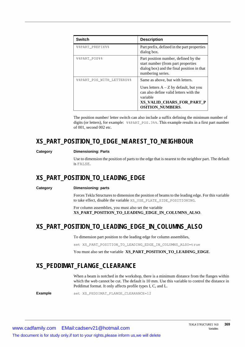
TEKLA STRUCTURES 14.0 369Variables
The position number/ letter switch can also include a suffix defining the minimum number of digits (or letters), for example: %%PART_POS.3%%. This example results in a first part number of 001, second 002 etc.
XS_PART_POSITION_TO_EDGE_NEAREST_TO_NEIGHBOURCategory Dimensioning: Parts
Use to dimension the position of parts to the edge that is nearest to the neighbor part. The default is FALSE.
XS_PART_POSITION_TO_LEADING_EDGECategory Dimensioning: parts
Forces Tekla Structures to dimension the position of beams to the leading edge. For this variable to take effect, disable the variable XS_USE_PLATE_SIDE_POSITIONING.
For column assemblies, you must also set the variable XS_PART_POSITION_TO_LEADING_EDGE_IN_COLUMNS_ALSO.
XS_PART_POSITION_TO_LEADING_EDGE_IN_COLUMNS_ALSOTo dimension part position to the leading edge for column assemblies,
set XS_PART_POSITION_TO_LEADING_EDGE_IN_COLUMNS_ALSO=true
You must also set the variable XS_PART_POSITION_TO_LEADING_EDGE.
XS_PEDDIMAT_FLANGE_CLEARANCEWhen a beam is notched in the workshop, there is a minimum distance from the flanges within which the web cannot be cut. The default is 10 mm. Use this variable to control the distance in Peddimat format. It only affects profile types I, C, and L.
Example set XS_PEDDIMAT_FLANGE_CLEARANCE=12
Switch Description
%%PART_PREFIX%% Part prefix, defined in the part properties dialog box.
%%PART_POS%% Part position number, defined by the start number (from part properties dialog box) and the final position in that numbering series.
%%PART_POS_WITH_LETTERS%% Same as above, but with letters.
Uses letters A – Z by default, but you can also define valid letters with the variable XS_VALID_CHARS_FOR_PART_POSITION_NUMBERS.
www.cadfamily.com EMail:[email protected] document is for study only,if tort to your rights,please inform us,we will delete
370 TEKLA STRUCTURES 14.0Variables
XS_PIXEL_TOLERANCECategory Model view
Use to define the snap zone of objects. Each object has a snap zone, which defines how close you need to pick to hit a position. When you pick within the snap zone of an object, Tekla Structures automatically snaps to the closest pickable point on that object. Enter the value in pixels.
See also Specifying points
XS_PLOT_ORIGIN_MOVE_XCategory Printing
Offsets the print origin in the x direction. Use if a drawing does not fit to the paper or is printed to a wrong location. Units are millimeters.
See also XS_PLOT_ORIGIN_MOVE_Y
XS_PLOT_ORIGIN_MOVE_YCategory Printing
Offsets the print origin in the y direction. Use if a drawing does not fit to the paper or is printed to a wrong location. Units are millimeters.
See also XS_PLOT_ORIGIN_MOVE_X
PML_ASSEMBLY_MARKS_IN_USECategory Export
Set this variable to any value to have Tekla Structures use assembly marks in PML exports. By default this variable is disabled and Tekla Structures uses part marks.
Using an incorrect value can cause problems in the workshop.
This variable affects all printers.
This variable affects all printers.
www.cadfamily.com EMail:[email protected] document is for study only,if tort to your rights,please inform us,we will delete

TEKLA STRUCTURES 14.0 371Variables
PML_CARDINAL_POINT_NOT_IN_USECategory Export
Set this variable to prevent Tekla Structures from using cardinal points in PML exports. This means that all parts will be defined by their center lines and their position may differ from that in the Tekla Structures model. By default this variable is disabled.
XS_PML_EXPORT_INCLUDE_GLOBAL_IDCategory Export
Use to revert to the FrameWorksPlus ID number in PML exports.
See also XS_SDNF_IMPORT_STORE_MEMBER_NUMBER.
XS_PML_EXPORT_USE_ADDITIONAL_CUT_DISTOlder versions of Tekla Structures added 1mm in length to fitted part ends in PML exports. Use this variable to force recent versions to also do this.
XS_POLYGON_CUT_EXTRA_THICKNESSCategory Modeling properties
Use to define the cut depth of a polygon cut, for example, to cut thick surface treatment. The default value for the cut thickness is 5.0 mm.
XS_POLYGON_PERPENDICULAR_EDGE_PREFERENCE_FACTORCategory Plate work
Use to rotate plates with perpendicular sides in drawings.
See also XS_POLYGON_SQUARE_CORNER_PREFERENCE_FACTOR.
XS_POLYGON_SQUARE_CORNER_PREFERENCE_FACTORCategory Plate work
Use to rotate right-angled plates in drawings. The longest side of polygon plates always faces downwards in drawings, which can affect right-angled plates as illustrated below:
Use this variable to prevent this happening. When this value is set to a factor, Tekla Structures multiplies the length of the side next to the right angle by that factor, making it the longest side. Tekla Structures still uses and displays the real dimensions of the plate.
www.cadfamily.com EMail:[email protected] document is for study only,if tort to your rights,please inform us,we will delete

372 TEKLA STRUCTURES 14.0Variables
XS_POP_MARK_COLORCategory Drawing Properties
Use to define the color of a customized pop-mark symbol that is displayed in a drawing. The default is 1.
See also XS_POP_MARK_SYMBOL (p. 372)
XS_POP_MARK_HEIGHT (p. 372)
XS_POP_MARK_HEIGHTCategory Drawing Properties
Use to define the height of a customized pop-mark symbol that is displayed in a drawing. Enter the value in millimeters. The default is 2.0.
See also XS_POP_MARK_SYMBOL (p. 372)
XS_POP_MARK_COLOR (p. 372)
XS_POP_MARK_SYMBOLCategory Drawing Properties
Use to define the location of a customized pop-mark symbol that is displayed in a drawing. The default is xsteel@0.
See also XS_POP_MARK_HEIGHT (p. 372)
XS_POP_MARK_COLOR (p. 372)
XS_POSITION_DIMENSIONS_FOR_HOLES_IN_SINGLE_SECONDARY_PARTS_IN_ASSEMBLY_DRAWINGCategory Dimensioning: bolts
To create position dimensions for holes in single secondary parts in assembly drawing, enter any value. To not create position dimensions for holes, clear the Value field.
SQUARE CORNER (2.0)
PERPENDICULAR EDGE (1.5)
www.cadfamily.com EMail:[email protected] document is for study only,if tort to your rights,please inform us,we will delete
TEKLA STRUCTURES 14.0 373Variables
XS_PRIMARY_PART_FIRSTCategory Templates and symbols
Set this variable to have Tekla Structures sort part and assembly part lists so that the main part of the assembly appears at the top of the list, immediately after the assembly.
XS_PRINT_MULTISHEET_BORDERCategory Drawing Properties
Use to define the borders that are left out from the smaller sheets when printing a drawing on multiple small sheets.
For example, to leave a 3 mm horizontal and a 5 mm vertical border, set the variable to 3,5.
XS_PRINT_REPORT_FONTSet to the name of a font to define the font for printed reports. Tekla Structures uses this variable if you do not specify a font for printed reports in the Print dialog box. If no font is given, Tekla Structures uses the default font.
Example set XS_PRINT_REPORT_FONT=Courier New
XS_PRINT_REPORT_LINE_WIDTH_LANDSCAPECategory Templates and symbols
Use to specify the number of characters per row in reports printed in landscape orientation.
See also XS_PRINT_REPORT_LINE_WIDTH_PORTRAIT
XS_PRINT_REPORT_PAGE_HEIGHT_LANDSCAPE
XS_PRINT_REPORT_PAGE_HEIGHT_PORTRAIT
XS_PRINT_REPORT_LINE_WIDTH_PORTRAITCategory Templates and symbols
Use to specify the number of characters per row in reports printed in portrait orientation.
See also XS_PRINT_REPORT_LINE_WIDTH_LANDSCAPE
XS_PRINT_REPORT_PAGE_HEIGHT_LANDSCAPE
XS_PRINT_REPORT_PAGE_HEIGHT_PORTRAIT
XS_PRINT_REPORT_PAGE_HEIGHT_LANDSCAPECategory Templates and symbols
Use to specify the number of rows in printed reports with landscape orientation.
See also XS_PRINT_REPORT_LINE_WIDTH_LANDSCAPE
XS_PRINT_REPORT_LINE_WIDTH_PORTRAIT
XS_PRINT_REPORT_PAGE_HEIGHT_PORTRAIT
www.cadfamily.com EMail:[email protected] document is for study only,if tort to your rights,please inform us,we will delete

374 TEKLA STRUCTURES 14.0Variables
XS_PRINT_REPORT_PAGE_HEIGHT_PORTRAITCategory Templates and symbols
Use to specify the number of rows in printed reports with portrait orientation.
See also XS_PRINT_REPORT_LINE_WIDTH_LANDSCAPE
XS_PRINT_REPORT_LINE_WIDTH_PORTRAIT
XS_PRINT_REPORT_PAGE_HEIGHT_LANDSCAPE
XS_PROFDBCategory File locations
Use to point to the profile folder which Tekla Structures searches for profile, material, device, and bolt catalogs.
You can store several catalogs in different locations, so it is important to know which catalog you are using. For more information, see Binary files (p. 55).
XS_PROFILE_ANALYSIS_CHECK_ALLCategory Analysis & Design
In the profile catalog you can enter analysis values for each profile. In the analysis, STAAD.Pro calculates the analysis values and compare them to the values in the profile catalog, and uses the values in the profile catalog, if they exist.
To check the profile catalog for analysis values for all profiles, enter TRUE in the Value field for
• XS_PROFILE_ANALYSIS_CHECK_ALL and• XS_AD_OPTIMISATION_DISABLED
After that, run the analysis.
If the profile catalog value differs significantly from the value STAAD.Pro calculates, Tekla Structures enters a warning in the analysis log file. Use the variable XS_PROFILE_ANALYSIS_VALUE_DIFF_LIMIT to define the warning limit.
XS_PROFILE_ANALYSIS_VALUE_DIFF_LIMITCategory Analysis & Design
Sets the warning limit when checking profile catalog analysis values. For more information, see XS_PROFILE_ANALYSIS_CHECK_ALL.
XS_PROFILE_DISPLAY_INCH_MARK_AFTER_FRACTIONS_IN_REPORTSCategory File locations
Use to define the location of the inch mark in profile lengths in reports.
To display the inch mark after the fractions (for example, PL1"X18 1/2"), enter TRUE. To display the inch mark before the fractions (for example, PL1"X18"1/2), enter FALSE.
By default, the inch mark is displayed after the fractions.
www.cadfamily.com EMail:[email protected] document is for study only,if tort to your rights,please inform us,we will delete

TEKLA STRUCTURES 14.0 375Variables
XS_PROJECTCategory File locations
Set the variables XS_PROJECT and XS_FIRM, along with XS_SYSTEM, to point to the folders Tekla Structures searches for properties files. Tekla Structures always saves properties in the current model folder. You can then copy or move them.
See also Folder search order (p. 59).
XS_PROTECT_SYMBOLSCategory Drawing properties
Set to prevent Tekla Structures drawing objects on top of symbols.
8.18 R
XS_RADIUS_TEXT_IN_UNFOLDING_BENDING_LINE_DIMENSIONINGCategory Dimensioning: unfolding
Use to set prefix text for radii.
XSR_BOLT_LENGTH_USE_ONLY_INCHESCategory Templates and symbols
Set to TRUE to prevent the variable XSR_USE_ZERO_FEET_VALUE affecting bolt length in bolt marks.
XSR_DIAMETER_USE_ONLY_INCHESUse to only output bolt diameter values in reports or drawing templates in inches. The result would be 0"3/4, not 0'-0"3/4.
XS_REBAR_BEND_MARK_SYMBOL_MIN_SIZECategory Concrete detailing
Use to increase the size of the reinforcing bar bend symbols in drawings (in drawing units) in order to see them more clearly.
See also Reinforcement appearance
XS_REBAR_DIMENSION_MARK_MANUAL_CLOSE_TO_GEOMETRYCategory Concrete Detailing
Use to add closing dimensions to the edge of the part in reinforcing bar group dimensions. The default TRUE means that the closing dimensions are added.
www.cadfamily.com EMail:[email protected] document is for study only,if tort to your rights,please inform us,we will delete

376 TEKLA STRUCTURES 14.0Variables
XS_REBAR_END_SYMBOL_MIN_SIZECategory Concrete detailing
Use to increase the size of the reinforcing bar end symbols in drawings (in drawing units) in order to see them more clearly. Works for 45 or 135 degree (see XS_REBAR_REVERSE_END_SYMBOLS) symbols.
See also Reinforcement appearance
XS_REBAR_MARK_LEADER_LINE_BASE_POINT_SEARCH_STEP_LENGTHCategory Concrete Detailing
Use to define the step length while searching for an optimal place for the mark leader line base point along the reinforcing bar. Enter the value in millimeters.
XS_REBAR_MARK_LEADER_LINE_BASE_POINT_SEARCH_TOLERANCECategory Concrete Detailing
Use to define how far the other reinforcing bars must be from the base point so that Tekla Structures can place the base point. Enter the value in millimeters.
XS_REBAR_PULLOUT_ANGLE_TEXT_FRAMECategory Concrete Detailing
Use to turn off the text frame around the angle text in pullout pictures. By default, this variable is set to TRUE.
XS_REBAR_RECOGNITION_HOOKS_CONSIDERATIONCategory Concrete Detailing
Set to FALSE to have Tekla Structures ignore hooks when it checks the shape of reinforcing bars, and to have Tekla Structures assign the same bending type to bars with and without hooks.
Set to TRUE to have Tekla Structures take the hooks into account and to treat bars with or without hooks, or with different hooks, as different.
The default value is TRUE.
XS_REBAR_REVERSE_END_SYMBOLSCategory Concrete detailing
Use to reverse the reinforcing bar end symbols to a different direction. When this variable is se to TRUE, the end symbol is drawn at 135 degree angle (used commonly in Norway).
See also XS_REBAR_END_SYMBOL_MIN_SIZE
XS_RECREATE_UNMODIFIED_DRAWINGSCategory Drawning Properties
www.cadfamily.com EMail:[email protected] document is for study only,if tort to your rights,please inform us,we will delete

TEKLA STRUCTURES 14.0 377Variables
Use to define whether drawings are recreated when you update an assembly, single or cast-unit drawing that has not been modifed. Drawings are automatically recreated unless they have been edited and then saved, or they have been issued using the Issue functionality in the drawing list.
To prevent the recreation of the unmodified drawings, set the variable FALSE.
To allow the recreation of the unmodified drawings, set the variable to TRUE.
XS_REFERENCE_CACHECategory File Locations
Use to define the default location of the cache file that is created from the source file when you load a reference model for the first time. The variable is set to C:\TeklaStructuresModels\\RefCacheFolders by default.
XS_REFERENCE_DGN_READ_COLORSCategory Import
Set to FALSE to view all reference model objects in gray.
XS_REFERENCE_DGN_READ_LINESCategory Import
Enter FALSE in the Value field to speed up the reading of reference .dgn files.
XS_REFERENCE_MODEL_HIDDEN_LINE_TYPECategory Drawing Properties
Use to choose the line type used to display the lines. See the following table for information on the different line types.
• You may sometimes want to change the default location of the cache file when you are working with multi-user models to reduce network traffic and disk usage in the server or to speed up the cache operation (if the local drive is faster than the server drive).
• When you are using different versions of Tekla Structures for different projects and you experience problems with reference models, empty the folder where the reference cache is created. The cache file is recreated the next time you open the reference model.
Set variable to Line type appearance
0 _____1
2
3
4
www.cadfamily.com EMail:[email protected] document is for study only,if tort to your rights,please inform us,we will delete

378 TEKLA STRUCTURES 14.0Variables
XS_REFERENCE_MODEL_LINES_HIDDEN_BY_ITSELFCategory Drawing Properties
Use to hide reference model lines if they are covered by the model itself. To hide covered reference lines, enter TRUE. To display covered lines, enter FALSE.
XS_REFERENCE_MODEL_LINES_HIDDEN_BY_OTHER_REFERENCE_MODELS Category Drawing Properties
Use to hide reference model lines if they are covered by other reference models. To hide covered reference model lines, enter TRUE. To display covered lines, enter FALSE.
XS_REFERENCE_MODELS_HIDE_PART_LINESCategory Drawing Properties
Use to hide part lines if they are covered by reference models. To hide covered part lines, enter TRUE. To display covered part lines, enter FALSE.
XS_REFERENCE_MODEL_LINES_HIDDEN_BY_PARTSCategory Drawing Properties
Use to hide reference model lines if they are covered by model parts. To hide covered reference model lines, enter TRUE. To display covered lines, enter FALSE.
XS_REFERENCE_ROUND_SEGMENTSCategory Import
Use to define the number of round segments to use in reference objects. The default is 16.
XS_REFERENCE_USE_RENDERED_CLIPPINGCategory Import
Set to TRUE to have Tekla Structures show only the center line of reference objects outside the work area in rendered views.
XS_RENDERED_CURSOR_LINE_WIDTHCategory Model view
5
6
7
Set variable to Line type appearance
www.cadfamily.com EMail:[email protected] document is for study only,if tort to your rights,please inform us,we will delete

TEKLA STRUCTURES 14.0 379Variables
Use to set cursor line width in rendered views. Enter the cursor line width in the Value field.
• Possible values are 1, 2, or 4. Any other value is handled as 1.• The default is 2.
XS_RENDERED_FOG_END_VALUESee XS_RENDERED_FOG_START_VALUE.
XS_RENDERED_FOG_START_VALUEIn rendered views distant objects appear progressively darker than close ones. Use the following variables to control the shade of objects:
set XS_RENDERED_FOG_START_VALUE=0.25
set XS_RENDERED_FOG_END_VALUE=0.50
Use values from 0 to 1 to control the shade of objects. The higher the value, the darker the distant objects.
Cursor line width of 1 Cursor line width of 4
Variables set to zero
Variables disabled
www.cadfamily.com EMail:[email protected] document is for study only,if tort to your rights,please inform us,we will delete

380 TEKLA STRUCTURES 14.0Variables
XS_RENDERED_PIXEL_TOLERANCE_SCALETekla Structures uses pixel tolerance to differentiate between clicking and dragging the mouse when zooming. Use this variable to define the pixel tolerance.
The default value is 0.7. If the mouse moves less than the value you specify with the mouse button depressed, it is treated as a click.
XS_REPORT_OUTPUT_DIRECTORYCategory File locations
Points to the folder where Tekla Structures saves reports. If the full path appears in the report file name field, Tekla Structures ignores this setting.
XS_ROTATE_CUT_VIEWSCategory Drawing view
Use to specify the rotation of section views.
BY_MAIN_VIEW (default) uses the same rotation as the orientation as the main view.
BY_SYMBOL_MAIN_VIEW uses the orientation of the view that contains the section symbol. This only applies to section views that Tekla Structures creates automatically. Manually-created views have the same rotation as the view they are created from.
www.cadfamily.com EMail:[email protected] document is for study only,if tort to your rights,please inform us,we will delete

TEKLA STRUCTURES 14.0 381Variables
XS_RUNPATHThis variable is available only in initialization files.
Use to point to the folder Tekla Structures searches for models by default. When you open the New dialog box, the default model folder is displayed in the Save in list box.
XSR_USE_NO_FEET_SEPARATORCategory Templates and symbols
Set to have Tekla Structures use a space instead of the feet separator in drawing tables and reports (US imperial environment only), e.g. 2 4''1/4.
You also need to set XSR_USE_NO_FEET_SYMBOL.
XSR_USE_NO_FEET_SYMBOLCategory Templates and symbols
Set to have Tekla Structures omit the feet symbol in drawing tables and reports (US imperial environment only), e.g. 2-4''1/4.
XSR_USE_NO_INCH_SYMBOLCategory Templates and symbols
Set to have Tekla Structures omit the inch symbol in drawing tables and reports (US imperial version only), e.g. 2-4 ¼ .
This variable does not affect the Open dialog box.
www.cadfamily.com EMail:[email protected] document is for study only,if tort to your rights,please inform us,we will delete
382 TEKLA STRUCTURES 14.0Variables
You also need to set XSR_USE_NO_FEET_SYMBOL and XSR_USE_NO_FEET_SEPARATOR.
XSR_USE_ZERO_FEET_VALUECategory Templates and symbols
Set to force Tekla Structures to show zero feet for values less one foot, e.g. 0'-6''3/4.
XSR_USE_ZERO_INCH_FOR_FRACTIONSCategory Templates and symbols
Set to force Tekla Structures to show zero inches for values only containing fractions, e.g. 2'-3/4 or 0''1/4.
XSR_USE_ZERO_INCH_VALUECategory Templates and symbols
Set to force Tekla Structures to show zero inches for values only containing feet and fractions, e.g. 2'-0''3/4 or 1/4.
8.19 S
XS_SAVE_WITH_COMMENTCategory Multi-user
Set to TRUE to enable the saving of model revision comments in multi-user models.
See also Saving model revision comments
XS_SCALE_COPIED_OR_MOVED_OBJECTS_IN_DRAWINGSCategory Drawing Properties
Use to define the scaling of objects that are copied or moved between drawing views that have different scales.
To scale the objects according to the view scales, set the varible to TRUE.
To keep the object sizes constant, set the variable to FALSE.
XS_SCALE_MARKS_TO_FIT_LIMITCategory Marking: parts
Tekla Structures fits part marks near the part they belong to by scaling the text height. Set the minimum scale with this variable.
Example XS_SCALE_MARKS_TO_FIT_LIMIT=0.5
www.cadfamily.com EMail:[email protected] document is for study only,if tort to your rights,please inform us,we will delete

TEKLA STRUCTURES 14.0 383Variables
The default value is 1.0 so that if you do not set the variable, Tekla Structures does not scale marks. Tekla Structures scales the text height in steps so that first it tries the scale of 0.9. If the mark does not fit, Tekla Structures scales the mark by 0.8, and so on.
Note that part mark's leader line type has to be either "Try along part" or "Always along part".
XS_SCREW_DIAMOND_WITHOUT_PHICategory Marking: bolts
Set to TRUE to prevent Tekla Structures placing a phi symbol outside the frame of bolt marks (diamond type only).
XS_SDNF_CONVERT_PL_PROFILE_TO_PLATECategory Export
Set to TRUE to have SDNF exports convert plate profiles (PL) to contour plates. Works with SDNF versions 2.0 and 3.0.
XS_SDNF_EXPORT_INCLUDE_GLOBAL_IDCategory Export
Use to revert to the FrameWorksPlus ID number in SDNF exports.
Example XS_SDNF_EXPORT_INCLUDE_GLOBAL_ID=TRUE
See also XS_SDNF_IMPORT_STORE_MEMBER_NUMBER.
XS_SDNF_IMPORT_STORE_MEMBER_NUMBERCategory Import
Set to TRUE to have Tekla Structures store the FrameWorksPlus ID number in SDNF imports. Tekla Structures stores the ID number in the user-defined attribute SDNF_MEMBER_NUMBER.
For information on exporting the ID number, see XS_SDNF_EXPORT_INCLUDE_GLOBAL_ID and XS_PML_EXPORT_INCLUDE_GLOBAL_ID.
XS_SECONDARY_PART_HARDSTAMPCategory CNC
Set to TRUE to include hard stamps for secondary parts in DSTV files. Set to FALSE to create hard stamps only for main parts.
Tekla Structures does not create hard stamps for plates.
www.cadfamily.com EMail:[email protected] document is for study only,if tort to your rights,please inform us,we will delete

384 TEKLA STRUCTURES 14.0Variables
XS_SECTION_LINE_COLORCategory Hatching
Use to add extra lines in different colors around automatic hatching in section views. Enter a value for the color (from 1 to 14) in the Value field.
• The default value is 0 (no extra lines).• The number corresponds to the color sequence in the drawing object properties:
XS_SECTION_SYMBOL_LEFT_ARROW_SYMBOLCategory Drawing properties
Use to define the arrow symbol Tekla Structures uses in section symbols at the left end of sections.
By default Tekla Structures uses the symbol no 145 in the sections.sym file (located usually in the folder \environments\country-independent\symbols\).
See also XS_SECTION_SYMBOL_RIGHT_ARROW_SYMBOL
Section view label and symbol.
XS_SECTION_SYMBOL_REFERENCECategory Drawing properties
Sets the reference text for symbols that show a section in another drawing. Enter the text in the Value field. The text can include:
• free text
To show lines around hatching, and to be able to add extra lines in different colors, you may need to set variable XS_DRAW_ALL_SECTION_EDGES_IN_DRAWINGS to TRUE in the initial-ization files. The variable is set to FALSE by default.
www.cadfamily.com EMail:[email protected] document is for study only,if tort to your rights,please inform us,we will delete

TEKLA STRUCTURES 14.0 385Variables
• user-defined attributes
• template attributes
If you set the variable in the Advanced options dialog box, use single % characters around the user-defined and template attributes. For example, %DRAWING_TITLE%.
If you set the variable in the initialization files, use double % characters around the user-defined and template attributes. For example, %%DRAWING_TITLE%%.
XS_SECTION_SYMBOL_RIGHT_ARROW_SYMBOLCategory Drawing properties
Use to define the arrow symbol Tekla Structures uses in section symbols at the right end of sections.
By default Tekla Structures uses the symbol no 144 in the sections.sym file (located usually in the folder \environments\country-independent\symbols\).
See also XS_SECTION_SYMBOL_LEFT_ARROW_SYMBOL
Section view label and symbol.
XS_SECTION_VIEW_REFERENCECategory Drawing properties
Sets the reference text for section view labels. See also XS_DETAIL_SYMBOL_REFERENCE.
XS_SEMI_ORTHO_ANGLESets the range for the semi-orthogonal snap as an angle. If you pick within the range, Tekla Structures snaps to the orthogonal position (0, 45, 90, 135, 180, etc. degrees).
Example XS_SEMI_ORTHO_ANGLE=15
See also XS_USE_SEMI_ORTHO (p. 406).
XS_SHOP_BOLT_MARK_STRING_FOR_SIZECategory Marking: Bolts
Use to define the contents of the Size element in bolt marks (workshop).
For switches available to define mark contents, see Size element in bolt marks.
XS_SHOP_BOLT_MARK_STRING_FOR_SIZE_IN_GACategory Marking: Bolts
www.cadfamily.com EMail:[email protected] document is for study only,if tort to your rights,please inform us,we will delete

386 TEKLA STRUCTURES 14.0Variables
Use to define the contents of the size element in bolt marks for workshop bolts in general arrangement drawings.
See also Size element in bolt marks
XS_SHOP_HOLE_MARK_STRING_FOR_SIZE_IN_GA (p. 386)
XS_SHOP_LONGHOLE_MARK_STRING_FOR_SIZE_IN_GA (p. 386)
XS_SHOP_HOLE_MARK_STRING_FOR_SIZECategory Marking: Bolts
Use to define the contents of the Size element in hole marks (workshop).
For switches to define mark contents, see Size element in bolt marks.
XS_SHOP_HOLE_MARK_STRING_FOR_SIZE_IN_GACategory Marking: Bolts
Use to define the contents of the size element in hole marks for workshop bolts in general arrangement drawings.
See also Size element in bolt marks
XS_SHOP_BOLT_MARK_STRING_FOR_SIZE_IN_GA (p. 385)
XS_SHOP_LONGHOLE_MARK_STRING_FOR_SIZE_IN_GA (p. 386)
XS_SHOP_LONGHOLE_MARK_STRING_FOR_SIZECategory Marking: Bolts
Use to define the contents of the Size element in slotted hole marks (workshop).
For switches to define mark contents, see Size element in bolt marks.
XS_SHOP_LONGHOLE_MARK_STRING_FOR_SIZE_IN_GACategory Marking: Bolts
Use to define the contents of the size element in longhole marks for workshop bolts in general arrangement drawings.
See also Size element in bolt marks
XS_SHOP_BOLT_MARK_STRING_FOR_SIZE_IN_GA (p. 385)
XS_SHOP_HOLE_MARK_STRING_FOR_SIZE_IN_GA (p. 386)
XS_SHOW_PERFORM_NUMBERING_MESSAGEUse to show or hide the Perform numbering button in the warning message Tekla Structures displays if you try to create a drawing without numbering or when numbering is not up to date.
• By default, this variable is set to TRUE and the numbering button is shown. • To hide the button, set this variable to FALSE.
Consider hiding the numbering button in the multi-user mode, because unnecessary or unplanned numbering may take a while in large models or break project numbering. This can
www.cadfamily.com EMail:[email protected] document is for study only,if tort to your rights,please inform us,we will delete

TEKLA STRUCTURES 14.0 387Variables
occur if Synchronize with master model (save-numbering-save) checkbox is not selected in the Numbering setup dialog box.
See also When to use multi-user mode (p. 58)
Numbering setup (p. 71)
Numbering – specific cases (p. 72)
XS_SHOW_REFERENCE_MODEL_HIDDEN_LINESCategory Drawing Properties
Use to display or hide the hidden lines of reference models in drawings. When you set the variable to TRUE, reference model lines are never hidden by other objects. To hide hidden lines, enter FALSE.
XS_SHOW_REVISION_MARK_ON_DRAWING_LISTCategory Drawing properties
Set to TRUE to have Tekla Structures include the Revision mark field in the Tekla Structures drawing list in the modeling environment, rather than the Revision number field (default).
XS_SHOW_SITE_STUDS_IN_ASSEMBLY_DRAWINGSCategory Drawing properties
Use to show site studs in assembly drawings.
XS_SHOW_STUDS_IN_WORKSHOP_DRAWINGSSet to TRUE to show workshop studs in single-part drawings.
XS_SHOW_TEMPLATE_LOG_MESSAGESCategory Templates and symbols
Use to show or hide the error messages related to template attributes in the log file. By default this variable is set to FALSE.
XS_SINGLE_CENTERED_SCREWCategory Single part view in assembly drawing
Use to control the dimensioning of centrally-located bolts in single-part views included in assembly drawings. See also Centered parts and bolts.
XS_SINGLE_CLOSE_DIMENSIONSCategory Single part view in assembly drawing
Use to close dimensions in single-part views included in an assembly drawing. See also Closing dimensions.
www.cadfamily.com EMail:[email protected] document is for study only,if tort to your rights,please inform us,we will delete

388 TEKLA STRUCTURES 14.0Variables
XS_SINGLE_CLOSE_SHORT_DIMENSIONSCategory Single part view in assembly drawing
Use to close short dimensions in single-part views included in assembly drawings. See also Closing dimensions.
XS_SINGLE_COMBINE_DISTANCECategory Single part view in assembly drawing
Use to set a distance for combining dimensions in single-part views included in assembly drawings. Enter a decimal value. See also Combining distances.
XS_SINGLE_COMBINE_MIN_DISTANCECategory Single part view in assembly drawing
Use to set a minimum distance for combining dimensions in single-part views included in assembly drawings. Enter a decimal value. See also Combining distances.
XS_SINGLE_COMBINE_WAYCategory Single part view in assembly drawing
Use to combine dimensions in single-part views included in assembly drawings. The five options (1,2,3,4,5) correspond to the combining order in the dimensioning properties dialog box. See also Combining distances.
XS_SINGLE_DIMENSION_TYPECategory Single part view in assembly drawing
Use to set a dimension type for single-part views included in assembly drawings. The options are:
• 1 relative• 2 absolute
• 3 both
XS_SINGLE_DRAW_PART_ASCategory Single part view in assembly drawing
Use to define how parts appear (their representation type) in single-part views included in assembly drawings. The options are:
• 1 solid• 4 workshop solid (round tubes open)
• 2 symbol form
www.cadfamily.com EMail:[email protected] document is for study only,if tort to your rights,please inform us,we will delete

TEKLA STRUCTURES 14.0 389Variables
XS_SINGLE_EXCLUDECategory Single Part View in Assembly Drawing
Use to exclude single-part views from assembly drawings. The options are:
• NONE includes all single part views.• MAIN_SHAFT includes single part views of all parts, except assembly main parts.
• ALL_SHAFTS includes single part views of all parts, except those with another object welded to them (i.e. primary parts).
• AUTOMATIC includes single part views of all parts, except the longest main part in the assembly.
• ALL_BUT_MAIN_PART includes single part views of assembly main parts only.
• STANDARD includes single-part views of all parts, except standard parts. You can add STANDARD after any of the existing values, for example MAIN_SHAFT_AND_STANDARD creates single-part drawing from all but main part or standard parts.
See also Standard part model.
XS_SINGLE_FORWARD_OFFSETCategory Single part view in assembly drawing
Use to set a forward offset for dimensions in single-part views included in an assembly drawing. Enter the value as a decimal. The forward offset defines how positions dimension lines. See also Forward offset.
XS_SINGLE_NO_RELATIVE_SHAPE_DIMENSIONSCategory Dimensioning: parts
Forces shape dimensions to be the same as the dimension type you select.
See also XS_NO_RELATIVE_SHAPE_DIMENSIONS
XS_SINGLE_NO_SHORTENCategory Single part view in assembly drawing
Use to display single-part views in drawings without shortening parts.
XS_SINGLE_ORIENTATION_MARKCategory Single part view in assembly drawing
You can create orientation marks for included single-part views in assembly drawings. To show the orientation marks in single-part views:
• Enter TRUE in the Value field for this variable.• Set the option Single-part attributes to Current attributes (in Assembly - layout
properties > Other). Tekla Structures takes the orientation mark settings from the current single-part drawing properties.
www.cadfamily.com EMail:[email protected] document is for study only,if tort to your rights,please inform us,we will delete

390 TEKLA STRUCTURES 14.0Variables
XS_SINGLE_PART_DRAWING_VIEW_TITLECategory Drawing properties
Use to define a title for single-part drawing views in a multi-drawings. You can use any of the following to define the title:
• PART_NAME
• PART_MATERIAL
• PART_POS
• ASSEMBLY_POS
• MODEL_NUMBER
• LENGTH, PROFILE
• LENGTH
• BASE_NAME
• NAME
XS_SINGLE_PART_EXTREMACategory Single part view in assembly drawing
Use to display overall dimensions in single-part views included in assembly drawings.
XS_SINGLE_PART_SHAPECategory Single part view in assembly drawing
Use to show or hide shape dimensions in single part views.
Set to 1 to show shape dimensions in single-part views.
Set to 0 to hide shape dimensions in single-part views.
XS_SINGLE_SCALECategory Single part view in assembly drawing
Use to set the scale of single-part views included in assembly drawings. Enter a decimal value.
Example To have Tekla Structures use the scale 1/10, enter 10.0 in the Value field.
XS_SINGLE_SCREW_INTERNALCategory Single part view in assembly drawing
Use to show or hide internal bolt dimensions in assembly drawings.
Set to 1 to show internal bolt dimensions.
Set to 0 to hide internal bolt dimensions.
See also Bolt internal dimensions.
www.cadfamily.com EMail:[email protected] document is for study only,if tort to your rights,please inform us,we will delete

TEKLA STRUCTURES 14.0 391Variables
XS_SINGLE_SCREW_POSITIONSCategory Single part view in assembly drawing
Use to include position dimensions for bolts in single-part views included in assembly drawings. See also Main part bolt positions.
XS_SINGLE_USE_WORKING_POINTSCategory Single part view in assembly drawing
Use to include dimensions from work points in single-part views included in assembly drawings.
XS_SINGLE_X_DIMENSION_TYPECategory Single part view in assembly drawing
Use to set the dimension type for single-part views included in assembly drawings. The options are:
• 1 relative• 2 absolute
• 3 both
XS_SITE_BOLT_MARK_STRING_FOR_SIZECategory Marking: Bolts
Use to define the contents of the Size element in bolt marks (site).
For switches you can use to define the contents, see Size element in bolt marks.
XS_SITE_BOLT_MARK_STRING_FOR_SIZE_IN_GACategory Marking: Bolts
Use to define the contents of the size element in bolt marks for site bolts in general arrangement drawings.
See also Size element in bolt marks
XS_SITE_HOLE_MARK_STRING_FOR_SIZE_IN_GA (p. 391)
XS_SITE_LONGHOLE_MARK_STRING_FOR_SIZE_IN_GA (p. 392)
XS_SITE_HOLE_MARK_STRING_FOR_SIZECategory Marking: Bolts
Use to define the contents of the Size element in hole marks (site).
For switches you can use for defining the contents, see Size element in bolt marks.
XS_SITE_HOLE_MARK_STRING_FOR_SIZE_IN_GACategory Marking: Bolts
www.cadfamily.com EMail:[email protected] document is for study only,if tort to your rights,please inform us,we will delete

392 TEKLA STRUCTURES 14.0Variables
Use to define the contents of the size element in hole marks for site bolts in general arrangement drawings.
See also Size element in bolt marks
XS_SITE_BOLT_MARK_STRING_FOR_SIZE_IN_GA (p. 391)
XS_SITE_LONGHOLE_MARK_STRING_FOR_SIZE_IN_GA (p. 392)
XS_SITE_LONGHOLE_MARK_STRING_FOR_SIZECategory Marking: Bolts
Use to define the contents of the Size element in slotted hole marks (site).
For switches you can use for defining the contents, see Size element in bolt marks.
XS_SITE_LONGHOLE_MARK_STRING_FOR_SIZE_IN_GACategory Marking: Bolts
Use to define the contents of the size element in longhole marks for site bolts in general arrangement drawings.
See also Size element in bolt marks
XS_SITE_HOLE_MARK_STRING_FOR_SIZE_IN_GA (p. 391)
XS_SITE_BOLT_MARK_STRING_FOR_SIZE_IN_GA (p. 391)
XS_SNAPSHOT_DIRECTORYCategory File locations
Points to the folder where Tekla Structures stores screenshots. If the variable is disabled, Tekla Structures stores screenshots in the current model folder.
If the defined folder does not exist, Tekla Structuresautomatically creates it when you take a screenshot.
Example XS_SNAPSHOT_DIRECTORY=c:\temp\
XS_SOLID_BUFFER_SIZECategory Speed and accuracy
Use to define the size of the solids buffer. The default value is 5000 solids.
Tekla Structures creates a buffer in system RAM to store the solid representation of parts it creates during certain processes. For example, Tekla Structures creates solids when numbering a model. When this buffer fills up, Tekla Structures erases the contents in order to continue using the buffer.
Increasing this value also increases the memory used by Tekla Structures processes. Decreasing this value decreases the memory requirements, but also decreases performance as Tekla Structures has to recreate solids more often.
Testing various settings is the best way to optimize solid buffer size. Remember opening Tekla Structures windows uses some RAM, and that other programs also use RAM for various processes.
www.cadfamily.com EMail:[email protected] document is for study only,if tort to your rights,please inform us,we will delete

TEKLA STRUCTURES 14.0 393Variables
Here are approximate recommendations for the solid buffer size, based on the amount of RAM your system has:
• 128 Mb memory - 10000• 256 Mb memory - 20000
• 512 Mb memory - 40000
XS_SOLID_USE_HIGHER_ACCURACYUse to model profiles more accurately in model views and drawings using profile roundings and sloping flanges. Using this variable also makes the weight value more accurate.
By default this variable is not used. To use this variable, add it to the user.ini file and set to TRUE.
Limitations • In components, some stiffeners might bite into flanges of columns or beams.• Some bolt edge distances are not correctly calculated.
XS_STACKED_FRACTION_TYPECategory Imperial units
Use to define the appearance of fractions. You can use stacked fractions in drawings, text, marks etc., but not in templates. The options are (from left to right in the illustration):
• NOT_STACKED
• DASH
• SLASH
• WITHOUT_SLASH
If you do not want to use stacked fractions, set this variable to NOT_STACKED, or use a backslash character ( \ ) before the slash character ( / ) in the text (e.g. 1\ /16).
XS_STANDARD_GUSSET_WIDTH_TOLERANCECategory Components
Use to define the tolerance between the actual and standard widths of gusset plates created using modeling tools or connections. Tekla Structures uses a standard plate file to define the default plate width including the tolerance value. Enter the value in millimeters.
Components that use this variable are:
• Welded gusset (10)
This variable increases the number of faces in solids, which slows down Tekla Structures. We recommend using this variable only when needed.
www.cadfamily.com EMail:[email protected] document is for study only,if tort to your rights,please inform us,we will delete

394 TEKLA STRUCTURES 14.0Variables
• Bolted gusset (11)
• Tube gusset (20)
• Corner tube gusset (56)
• Corner bolted gusset (57)
• Wraparound gusset (58),
• Hollow brace wraparound gusset (59)
• Wraparound gusset cross (60)
• Gusseted cross (62)
• Corner wrapped gusset (63)
XS_STANDARD_STIFFENER_WIDTH_TOLERANCECategory Components
Use to define the tolerance between the actual and standard widths of stiffener plates created by Haunch (40). Enter the value in millimeters. The variable is set to 10 by default.
XS_STD_PART_MODELCategory Numbering
Use to indicate the location of the standard part model.
Enter the folder path.
Example XS_STD_PART_MODEL=C:\TeklaStructures\Models\Stand
XS_SUPERSCRIPT_HEIGHT_FACTORCategory Dimensioning: General
Use the variable to set the scale factor for the text height in superscripts used in dimensions. The default is 0.7.
Examples
www.cadfamily.com EMail:[email protected] document is for study only,if tort to your rights,please inform us,we will delete

TEKLA STRUCTURES 14.0 395Variables
XS_SWITCH_MULTI_NUMBERS_FORCategory Numbering
Use to define the order in which multi-drawing numbers, and part or assembly numbers appear in multi-numbers. The options are: NONE, ASSEMBLIES, PARTS and ASSEMBLIES_AND_PARTS.
Example If this variable is set to PARTS, the presentation of multinumbers for parts is 101a, not a101.
XS_SWITCH_POS_NUMBERS_FORCategory Numbering
Changes the prefix you define for Tekla Structures assembly and/or part marks to a suffix (for example, A1 becomes 1A). The options are NONE, PARTS, ASSEMBLIES, ASSEMBLIES_AND_PARTS.
SYMEDHOMECategory Templates and symbols
Points to the location of the symbol editor message file.
XS_SYSTEMCategory File locations
Points to the location of the Tekla Structures system folder.
Specifying more than one system directory
You can specify more than one system folder. To do this, enter the file paths of the folders, separated by semicolons (for example, C:\TeklaStructures\14.0\usimp\system_steel; C:\TeklaStructures\14.0\usimp\system_common), as the value for the variable.
Tekla Structures searches the folders in the order that you have entered them. If files with identical names exist in both folders, the one that is found first will be used. In the example above, the files found from system_steel will be used instead of the files with identical names in system_common.
See also Folder search order (p. 94)
Example number The variable is set to
0.7
1.5
0.5
www.cadfamily.com EMail:[email protected] document is for study only,if tort to your rights,please inform us,we will delete

396 TEKLA STRUCTURES 14.0Variables
8.20 T
TEMPLATE_FONT_CONVERSION_FILECategory Templates and symbols
Points to the location of the template font conversion file (template_fonts.cnv).
XS_TEMPLATE_DIRECTORYCategory File locations
Points to the location of the folder containing template (*.tpl) and report (*.rpt) files.
See also Folder search order.
XS_TEMPLATE_DIRECTORY_SYSTEMCategory File locations
Use to set the path to the default environment-specific templates delivered with Tekla Structures.
See also Folder search order.
XS_TEXT_FONTNo help available.
XS_TEXT_HEIGHT_FACTORUse to fine-tune Tekla Structures font heights when you are using the "Custom %" setting in Windows 2000 font size setup
Example set XS_TEXT_HEIGHT_FACTOR=1.0
XS_TEXT_ORIENTATION_EPSILONCategory Drawing Properties
Use to define the point where text that is positioned almost vertically is turned so that it is faced the other way around. The default is 0.1.
www.cadfamily.com EMail:[email protected] document is for study only,if tort to your rights,please inform us,we will delete

TEKLA STRUCTURES 14.0 397Variables
TEXT_X_SIZEUse to change font size in the Template Editor
Example set TEXT_X_SIZE=3
TEXT_Y_SIZEUse to change font size in the Template Editor
Example TEXT_Y_SIZE=5
XS_THUMBNAIL_FONTCategory Model view
Use to set the font used in the component catalog.
XS_TPLED_INICategory Templates and symbols
Defines the location of the tpled.ini file.
Example XS_TPLED_INI=%XS_DIR%\environments\%2\template\settings\
XS_TRY_TO_KEEP_LOCATION_IN_FREEPLACINGCategory Drawing properties
Use to fine-tune the functionality of the Arrange Drawing Objects command in the Drawing Editor.
This variable is set to TRUE by default, meaning that the Arrange Drawing Objects command tries to find a new location for the selected object as close to the current location as possible. If the current location is free, the object is not moved at all.
When this variable is set to FALSE, the Arrange Drawing Objects command works the same way as Ignore Current Locations.
www.cadfamily.com EMail:[email protected] document is for study only,if tort to your rights,please inform us,we will delete

398 TEKLA STRUCTURES 14.0Variables
XS_TUBE_UNWRAP_LIMIT_THICKNESSCategory Drawing properties
Use to define how Tekla Structures draws tubes.
Set to a decimal value. Tekla Structures individually draws the inner and outer surfaces of tubes thicker than this value
Example XS_TUBE_UNWRAP_LIMIT_THICKNESS=16.0
XS_TUBE_UNWRAP_PAPER_THICKNESSCategory Drawing properties
Lengthens unfolded tubes by the following multiplication factor:
factor = 1.0+2*XS_TUBE_UNWRAP_PAPER_THICKNESS/diameter
Example Tube d=219
When you set the variable to 0, the unwrapped length of the tube (1.0*PI*diameter) = 688.
When the variable is set to 10, the length of the unfolded tube = factor * diameter* PI = (1.0 + 2*10/219) * 219 * 3.14 = 751
XS_TUBE_UNWRAP_USE_PLATE_PROFILE_TYPE_IN_NCCategory CNC
To use the plate profile type B in the NC file header data for unwrapped round tubes, set to TRUE. To use RO for round tubes, enter FALSE.
XS_TUBE_UNWRAP_WITH_CUT_HOLESCategory Drawing properties
Set to TRUE to include cut holes in workshop drawings or NC files of unwrapped CHS (circular hollow section) profiles.
This variable is set to TRUE by default. If you set it to FALSE, then the previously existing unwrapping method is applied.
Use this variable only when you have set the variable XS_TUBE_UNWRAP_WITH_CUT_HOLES to TRUE.
www.cadfamily.com EMail:[email protected] document is for study only,if tort to your rights,please inform us,we will delete
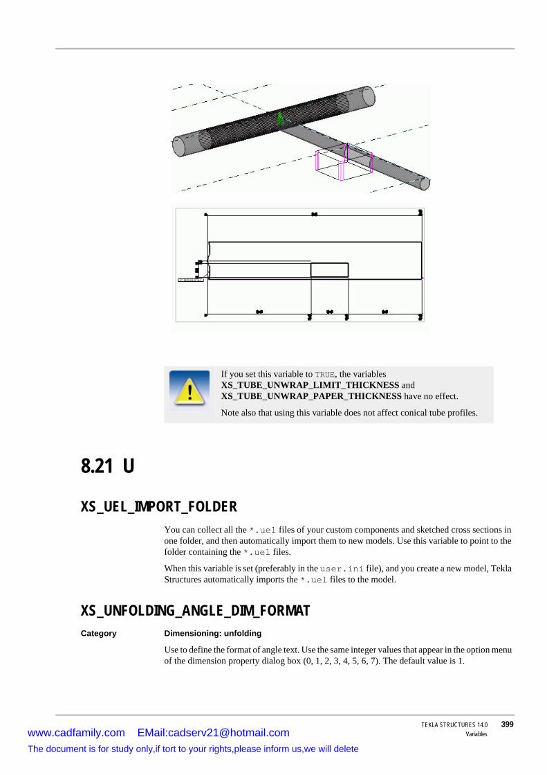
TEKLA STRUCTURES 14.0 399Variables
8.21 U
XS_UEL_IMPORT_FOLDERYou can collect all the *.uel files of your custom components and sketched cross sections in one folder, and then automatically import them to new models. Use this variable to point to the folder containing the *.uel files.
When this variable is set (preferably in the user.ini file), and you create a new model, Tekla Structures automatically imports the *.uel files to the model.
XS_UNFOLDING_ANGLE_DIM_FORMATCategory Dimensioning: unfolding
Use to define the format of angle text. Use the same integer values that appear in the option menu of the dimension property dialog box (0, 1, 2, 3, 4, 5, 6, 7). The default value is 1.
If you set this variable to TRUE, the variables XS_TUBE_UNWRAP_LIMIT_THICKNESS and XS_TUBE_UNWRAP_PAPER_THICKNESS have no effect.
Note also that using this variable does not affect conical tube profiles.
www.cadfamily.com EMail:[email protected] document is for study only,if tort to your rights,please inform us,we will delete

400 TEKLA STRUCTURES 14.0Variables
XS_UNFOLDING_ANGLE_DIM_PRECISIONCategory Dimensioning: unfolding
Use to define the precision of angle text. Use the same integer values that appear in the option menu of the dimension property dialog box (1, 2, 3, 4, 8, 16, 32, 10, 100, 1000). The default value is 10.
XS_UNFOLDING_DONT_USE_NEUTRAL_AXIS_FOR_RADIUSCategory Dimensioning: unfolding
By default, Tekla Structures uses the neutral axis of the part to calculate the bending radius in unfolded views. Set this variable to TRUE to have Tekla Structures calculate the bending radius from the inner surface of the part.
XS_UNFOLDING_PLANE_EPSILONCategory Dimensioning: Unfolding
Use to specify the epsilon when checking if all section points are on the same plane. The default value is 0.01 mm.
XS_UNIQUE_NUMBERSCategory Numbering
Set this variable to have Tekla Structures create unique position numbers for all parts when numbering, even if they are equal.
See also XS_UNIQUE_ASSEMBLY_NUMBERS (p. 400)
XS_UNIQUE_ASSEMBLY_NUMBERSCategory Numbering
Set to TRUE if you want Tekla Structures to create unique position numbers for all assemblies when numbering, even if they are identical.
Parts are still numbered the same way as before.
The default value is FALSE.
See also XS_UNIQUE_NUMBERS (p. 400)
XS_UPDATE_MARK_PLACING_IN_DRAWINGCategory Marking: parts
Updates the position of updated marks in specific drawing types. Use the letters in the following table to specify the drawing types. By default, this variable applies to single-part, assembly, and multi-drawings.
www.cadfamily.com EMail:[email protected] document is for study only,if tort to your rights,please inform us,we will delete

TEKLA STRUCTURES 14.0 401Variables
Example To update the position of updated part marks in single-part, assembly, multi-, and general arrangement drawings:
XS_UPDATE_MARK_PLACING_IN_DRAWING=WAMG
XS_UPDATE_MARKS_IN_FROZEN_DRAWINGSCategory Marking: general
Set to TRUE to have Tekla Structures to update marks in frozen drawings and also create new marks if new parts have been added. If disabled Tekla Structures only updates parts and bolts.
XS_UPSIDE_DOWN_TEXT_ALLOWEDCategory Concrete detailing
Set toTRUE to place part marks or other text upside down to illustrate that identical parts have a different orientation. If you do not set this variable, Tekla Structures automatically changes all marks or text that are rotated more than 90 degrees.
XS_USABSOLUTE_TO_RELATIVE_LIMITCategory Dimensioning: general
Use to affect the distance within which the first and last US Absolute dimension lines appear as relative.
Example XS_USABSOLUTE_TO_RELATIVE_LIMIT=1000
In this example, Tekla Structures will change first and last dimension lines shorter than 1000 mm to Relative dimensions. Dimension lines greater or equal to 1000 mm will remain US Absolute dimensions.
XS_USABSOLUTE2_TO_RELATIVE_LENGTH_FACTORCategory Dimensioning: general
Tekla Structures multiplies the space required by US Absolute2 dimension text by this value. If the result is larger than the actual dimension, Tekla Structures changes the dimension type to Relative. The default value is 1.5.
XS_USE_ASSEMBLY_NUMBER_FORCategory Numbering
Letter Drawing type
W Single-part drawingsA Assembly drawingsM Multi-drawingsG General arrangement drawingsC Cast-unit drawings
www.cadfamily.com EMail:[email protected] document is for study only,if tort to your rights,please inform us,we will delete

402 TEKLA STRUCTURES 14.0Variables
Makes the assembly or cast unit number the part number of main parts in assemblies or cast units.
• Set to MAIN_PART to assign the assembly or cast unit number to the main parts of an assembly or cast unit. All other parts use part number.
• Set to LOOSE_PART to assign the assembly or cast unit number to the assemblies or cast units that only contain one part.
XS_USE_BOLT_DISTANCE_IN_NOTCH_CALCULATIONSSet to TRUE to use automatic notch height calculation according to bolt distance. This affects connections 129 and 184.
XS_USE_COLOR_DRAWINGSCategory Drawing view
Changes the default color mode in drawings when the Tekla Structures is started. By default, drawings are black and white. Set to TRUE to use colors in drawings.
XS_USE_CONVEX_PROTECT_AREACategory This variable is available only in initialization files.
Set to TRUE to have Tekla Structures calculate the protection area more accurately along the faces of parts so that part marks can be placed inside the profile also for curved hollow sections. The variable is set to TRUE by default.
XS_USE_DRAWING_NAME_AS_PLOT_FILE_NAMEUse to prevent Tekla Structures converting the dot in the drawing name (e.g. B.1) to an underscore in the plot file name when printing.
XS_USE_DRAWING_NAME_AS_PLOT_TITLECategory Printing
Set to TRUE when you want Tekla Structures to use the drawing name as the print title, for example, when printing to a .pdf file or to a Windows printer.
As a result, the Windows printer dialog box, for example, will show the drawing plot file name you define with variables and not the general Tekla Structures print title, such as "Tekla Structures drawing - A [T.100]".
See also XS_DRAWING_PLOT_FILE_NAME.
Do not use the same prefix for parts and assemblies.
www.cadfamily.com EMail:[email protected] document is for study only,if tort to your rights,please inform us,we will delete
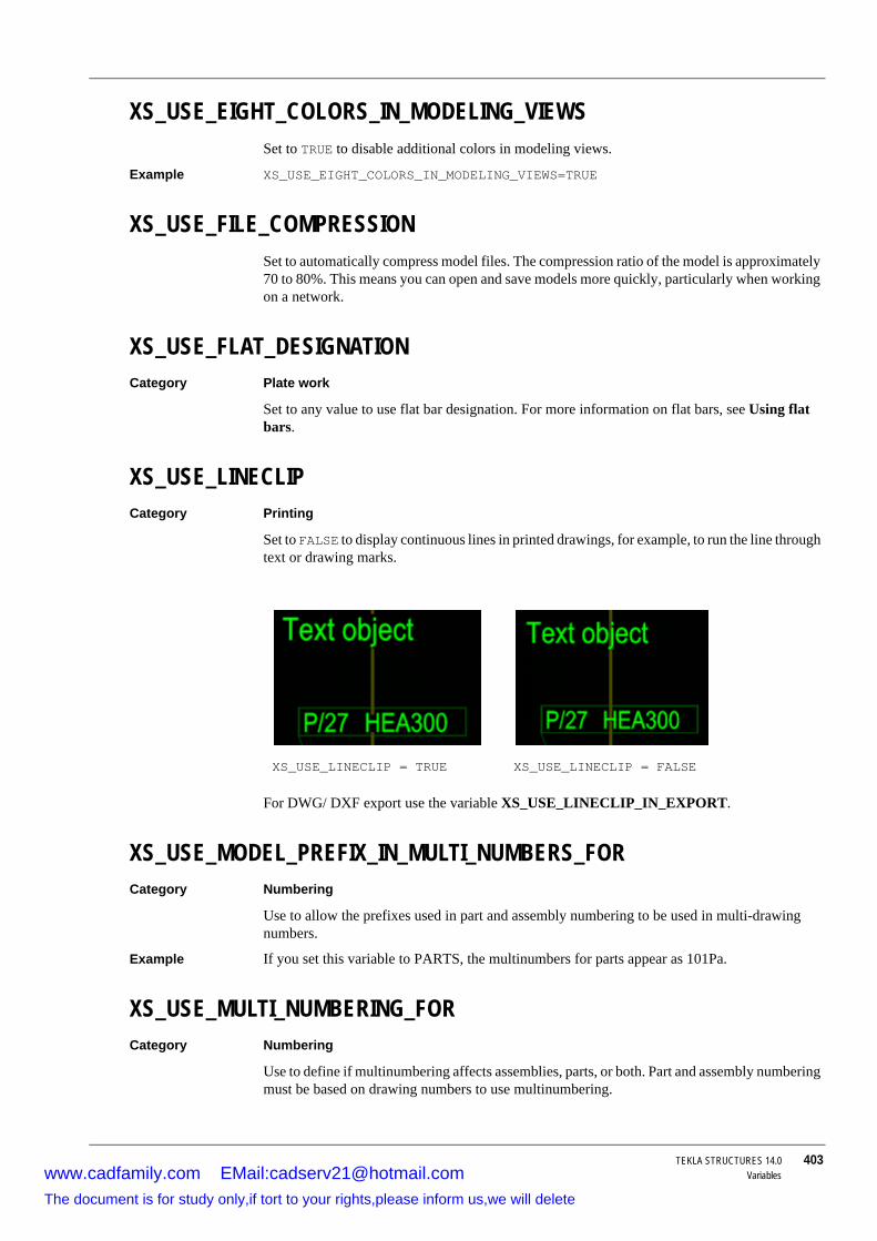
TEKLA STRUCTURES 14.0 403Variables
XS_USE_EIGHT_COLORS_IN_MODELING_VIEWSSet to TRUE to disable additional colors in modeling views.
Example XS_USE_EIGHT_COLORS_IN_MODELING_VIEWS=TRUE
XS_USE_FILE_COMPRESSIONSet to automatically compress model files. The compression ratio of the model is approximately 70 to 80%. This means you can open and save models more quickly, particularly when working on a network.
XS_USE_FLAT_DESIGNATIONCategory Plate work
Set to any value to use flat bar designation. For more information on flat bars, see Using flat bars.
XS_USE_LINECLIPCategory Printing
Set to FALSE to display continuous lines in printed drawings, for example, to run the line through text or drawing marks.
For DWG/ DXF export use the variable XS_USE_LINECLIP_IN_EXPORT.
XS_USE_MODEL_PREFIX_IN_MULTI_NUMBERS_FORCategory Numbering
Use to allow the prefixes used in part and assembly numbering to be used in multi-drawing numbers.
Example If you set this variable to PARTS, the multinumbers for parts appear as 101Pa.
XS_USE_MULTI_NUMBERING_FORCategory Numbering
Use to define if multinumbering affects assemblies, parts, or both. Part and assembly numbering must be based on drawing numbers to use multinumbering.
XS_USE_LINECLIP = TRUE XS_USE_LINECLIP = FALSE
www.cadfamily.com EMail:[email protected] document is for study only,if tort to your rights,please inform us,we will delete

404 TEKLA STRUCTURES 14.0Variables
The options are:
• NONE
• ASSEMBLIES
• PARTS
• ASSEMBLIES_AND_PARTS
XS_USE_MULTI_NUMBERING_WHEN_COPYING_DRAWING_VIEWSCategory Numbering
To use multinumbering when copying drawing views, enter TRUE in the Value field. To not use multinumbering, clear the Value field.
XS_USE_NEW_CLASH_CHECKCategory Modeling Properties
If you are working on a large model, running the clash check may sometimes be slow. In that case you can use the old clash checking functionality, which does not recognize clashes with reference models.
To revert to the old functionality, set the variable to FALSE. The default value is TRUE.
XS_USE_NEW_PLATE_DESIGNATIONCategory Plate work
Set to TRUE to switch the width and length values, if the width is greater than the length.
Exampole A beam with profile BL15*240 and the distance between beam endpoints is 215 mm.
• If XS_USE_NEW_PLATE_DESIGNATION is set, the length of the beam is fixed at 240, and the beam profile changes to BL15*215.
• If XS_USE_NEW_PLATE_DESIGNATION is not set, the length of the beam is to 215 and the profile remains BL15*240
XS_USE_NEW_WELD_PLACINGIf you have set welds visible in the drawing, this variable affects in which drawing view (front, back, top, or bottom) Tekla Structures draws the welds.
• When the variable is set to TRUE, Tekla Structures draws welds to the view in which has best visibility to the secondary part.
• When the variable is not set, Tekla Structures selects the view according to the primary part.
XS_USE_NEW_USNOTCHUse to indicate whether to locate the horizontal cut of a notch above or below the flange of the main beam.
Used with the following notching options:
www.cadfamily.com EMail:[email protected] document is for study only,if tort to your rights,please inform us,we will delete

TEKLA STRUCTURES 14.0 405Variables
XS_USE_NUMERIC_MULTI_NUMBERS_FORCategory Numbering
Use to define which objects have numeric multi-numbers.The options are:
• ASSEMBLIES
• PARTS
• ASSEMBLIES_AND_PARTS
Example If you set this variable to PARTS, Tekla Structures displays the multinumber as e.g. 101/1. If you also set the variable XS_USE_MODEL_PREFIX_IN_MULTI_NUMBERS_FOR to PARTS, Tekla Structures replaces the slash character with the part prefix, e.g. 101P1.
XS_USE_OLD_FILTERINGCategory Modeling Properties
Use to change the appearance of the Object Group - Select Filter dialog box.
The default value is FALSE.
See also Select filter dialog box
XS_USE_OLD_HQ_PROFILE_DEFINITIONCategory Profiles
Set to use the old HQ profile definition. In the old HQ profile definition, profile height is the total height from the lower surface of the lower flange to the top of the upper flange.
The new HQ profile definition omits the lower flange thickness and the profile height is equal to the web height.
XS_USE_OLD_POLYBEAM_LENGTH_CALCULATIONNo help available.
XS_USE_ONLY_INCHES_IN_SHEET_SIZESCategory Imperial units
Set to 1 to have sheet sizes in layouts and drawing lists in inches.
XS_USE_ONLY_INCHES_IN_WELD_LENGTHCategory Imperial units
Set to TRUE to only display inches in weld length symbols.
www.cadfamily.com EMail:[email protected] document is for study only,if tort to your rights,please inform us,we will delete

406 TEKLA STRUCTURES 14.0Variables
XS_USE_ONLY_NOMINAL_REBAR_DIAMETERCategory Concrete detailing
Nominal diameter defines the cross section area of the reinforcing bar. To use nominal diameter for reinforcing bars, enter TRUE in the Value field. To use actual diameter, clear the Value field. (Actual diameter takes into account the "embosses" and tells the smallest hole diameter where the bar fits.)
XS_USE_PLATE_SIDE_POSITIONINGCategory Dimensioning: parts
Use to make the position dimension of plates dependent on the position of plates in the model.
Example Where a plate is positioned behind the reference points, Tekla Structures will place the position dimension on the top face of the plate.
XS_USE_POINT_AS_SEPARATOR_IN_PROFILE_NAMESet to use the period character (.) as the separator in parametric profile names, instead using it as a decimal separator. This increases the number of separators available in the US imperial environment.
XS_USE_SEMI_ORTHOSet to FALSE when you want to use full orthogonal snapping. With full orthogonal snapping, Tekla Structures can only to snap to positions in orthogonal directions (0, 45, 90, 135, 180, etc. degrees) on the work plane.
When set to TRUE (default), Tekla Structures uses semi-orthogonal snapping, which enables you to pick orthogonal positions within a tolerance which you set with XS_SEMI_ORTHO_ANGLE. Outside the tolerance you can pick any position.
XS_USE_SMALLER_GUSSET_PLATECategory Components
Set to TRUE to minimize the size of rectangular gusset plates created by gusset connections. You can create smaller gusset plates by using a single bracing and secondary bolts dimensioned to the middle of the secondary part. Tekla Structures generates a triangular gusset plate when the primary part is located between diagonals.
XS_USE_SMOOTH_LINESCategory Model view
Set to TRUE to have Tekla Structures use anti-aliasing to minimize jagged edges in rendered views. Before using this variable, check that your display adapter supports anti-aliasing.
XS_USE_SOFTWARE_RENDERINGCategory Model view
www.cadfamily.com EMail:[email protected] document is for study only,if tort to your rights,please inform us,we will delete

TEKLA STRUCTURES 14.0 407Variables
Set to TRUE to have Tekla Structures bypass your graphic adapter in rendered views. Use this variable if you have problems with your display (e.g. lines not correctly drawn.
XS_USE_SPECIAL_FILLER_PLATE_THICKNESSSet to TRUE to have filler plate thicknesses comply with Japanese standards.
XS_USE_TUBE_INNER_LENGTH_IN_DIMENSIONINGCategory Dimensioning: parts
Set to TRUE to have Tekla Structures dimension the overall length of tube profiles along the inner surface instead of outer surface.
XS_USE_VERTICAL_PLACING_FOR_COLUMNS_INCategory Drawing properties
Use to place columns vertically in drawings. Use the following options to specify the types of columns to place vertically:
• ASSEMBLY_DRAWINGS
• SINGLE_PART_DRAWINGS
• ASSEMBLY_AND_SINGLE_PART_DRAWINGS
XS_USER_DEFINED_BOLT_SYMBOL_TABLECategory Marking: bolts
Defines the location of the user-defined bolt symbol table file.
XS_USER_DEFINED_PARAMETRIC_PROFILE_SEPARATORS Category Profiles
Use to define additional separators to separate dimensions in the names of parametric profiles. The separators can consist of multiple characters.
Separate the values with commas, for example GA,ABC.
In addition to these characters, Tekla Structures always recognizes the standard separator characters X, *, -, and /, and also the character defined by the variable XS_PARAMETRIC_PROFILE_SEPARATOR.
Follow these rules in naming:
• Use upper case letters in separator names.• Do not enter digits, commas, or special characters in separator
names.
• Do not start separator names with a dash (-) or full stop (.).
• Do not start separator names with an inch separator (", ', /) when using imperial units.
www.cadfamily.com EMail:[email protected] document is for study only,if tort to your rights,please inform us,we will delete

408 TEKLA STRUCTURES 14.0Variables
8.22 V
XS_VALID_CHARS_FOR_ASSEMBLY_FAMILY_POSITION_NUMBERSCategory Numbering
Specifies valid characters for assembly family position numbers. You must specify all the valid characters in this variable.
See also XS_ASSEMBLY_FAMILY_POSITION_NUMBER_FORMAT_STRING
XS_VALID_CHARS_FOR_ASSEMBLY_FAMILY_QUALIFIERCategory Numbering
Specifies valid characters for the assembly family number qualifier. You must specify all the valid characters in this variable.
Example XS_VALID_CHARS_FOR_ASSEMBLY_FAMILY_QUALIFIER=GHJKL
See also XS_ASSEMBLY_FAMILY_POSITION_NUMBER_FORMAT_STRING
XS_VALID_CHARS_FOR_ASSEMBLY_MULTI_NUMBERSCategory Numbering
Use to specify the valid characters for assembly multinumbers. You must specify all the valid characters in this variable.
Example XS_VALID_CHARS_FOR_ASSEMBLY_MULTI_NUMBERS=abeg
XS_VALID_CHARS_FOR_ASSEMBLY_POSITION_NUMBERS Category Numbering
Specifies valid characters for assembly position numbers. See also XS_ASSEMBLY_POSITION_NUMBER_FORMAT_STRING.
XS_VALID_CHARS_FOR_PART_MULTI_NUMBERSCategory Numbering
Use to specify the valid characters for part multinumbers. You must specify all the valid characters in this variable.
Example XS_VALID_CHARS_FOR_PART_MULTI_NUMBERS=ABEG
XS_VALID_CHARS_FOR_PART_POSITION_NUMBERSCategory Numbering
Use to specify the valid characters for part position numbers. See also XS_PART_POSITION_NUMBER_FORMAT_STRING (p. 368).
www.cadfamily.com EMail:[email protected] document is for study only,if tort to your rights,please inform us,we will delete

TEKLA STRUCTURES 14.0 409Variables
XS_VIEW_DIM_LINE_COLORCategory Model View
Use to change the dimension line color in rendered views. Define the color using RGB values:
XS_VIEW_DIM_LINE_COLOR=<value for red> <value for green> <value for blue>.
Separate the values with spaces. Define the values on a scale of 0 to 1. Restart Tekla Structures for the change to take effect.
Example
XS_VIEW_DIM_TEXT_COLORCategory Model View
Use to change the dimension text color in rendered views. Define the color using RGB values:
XS_VIEW_DIM_TEXT_COLOR=<value for red> <value for green> <value for blue>.
Separate the values with spaces. Define the values on a scale of 0 to 1. Restart Tekla Structures for the change to take effect.
Example
XS_VIEW_FAST_BOLT_COLORCategory Model View
Use to define the color of bolts in rendered views when you are using the bolt representation option Fast. Define the color using the RGB (Red Green Blue) values. The scale is from 0 to 1.
Example For example, use 0.0 0.0 0.0 for black and 1.0 1.0 1.0 for white.
XS_VIEW_FREE_MEASURE_PLANECategory Model View
RGB value Color
1.0 1.0 1.0 White1.0 0.0 0.0 Red0.0 1.0 0.0 Green0.0 0.0 1.0 Blue1.0 1.0 0.0 Yellow
RGB value Color
1.0 1.0 1.0 White1.0 0.0 0.0 Red0.0 1.0 0.0 Green0.0 0.0 1.0 Blue1.0 1.0 0.0 Yellow
www.cadfamily.com EMail:[email protected] document is for study only,if tort to your rights,please inform us,we will delete
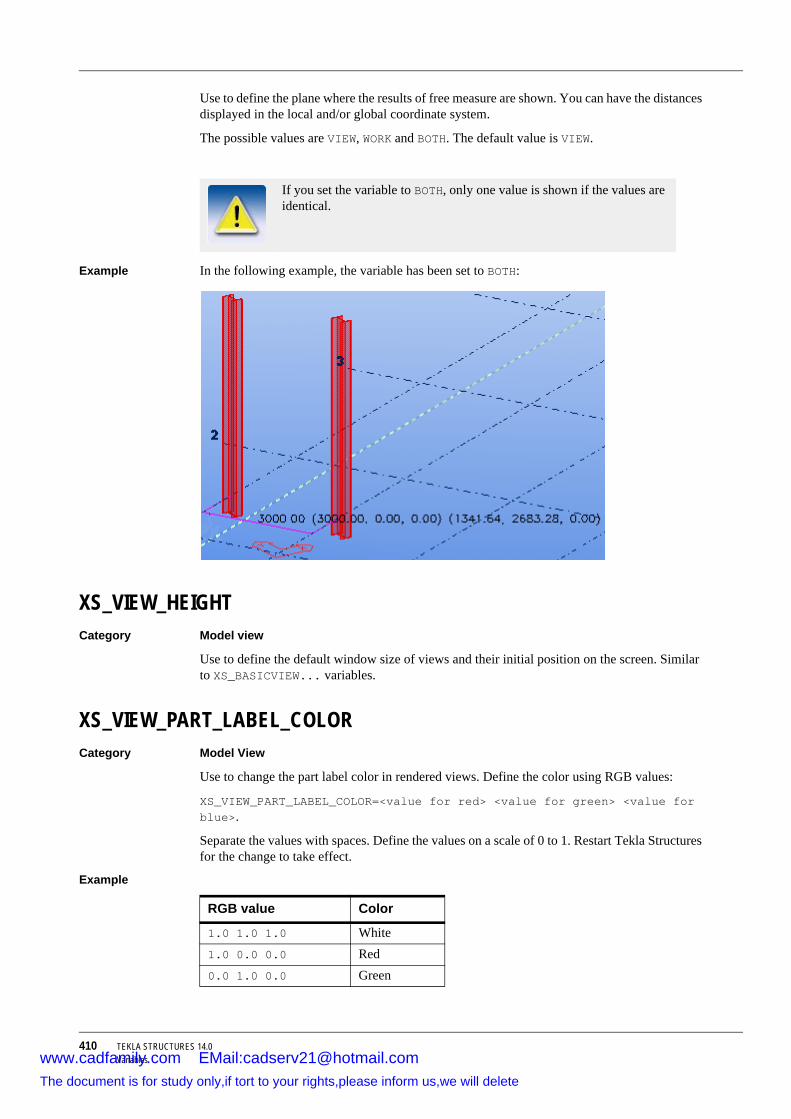
410 TEKLA STRUCTURES 14.0Variables
Use to define the plane where the results of free measure are shown. You can have the distances displayed in the local and/or global coordinate system.
The possible values are VIEW, WORK and BOTH. The default value is VIEW.
Example In the following example, the variable has been set to BOTH:
XS_VIEW_HEIGHTCategory Model view
Use to define the default window size of views and their initial position on the screen. Similar to XS_BASICVIEW... variables.
XS_VIEW_PART_LABEL_COLORCategory Model View
Use to change the part label color in rendered views. Define the color using RGB values:
XS_VIEW_PART_LABEL_COLOR=<value for red> <value for green> <value for blue>.
Separate the values with spaces. Define the values on a scale of 0 to 1. Restart Tekla Structures for the change to take effect.
Example
If you set the variable to BOTH, only one value is shown if the values are identical.
RGB value Color
1.0 1.0 1.0 White1.0 0.0 0.0 Red0.0 1.0 0.0 Green
www.cadfamily.com EMail:[email protected] document is for study only,if tort to your rights,please inform us,we will delete
TEKLA STRUCTURES 14.0 411Variables
XS_VIEW_POSITION_XCategory Model view
Use to define the default window size of views and their initial position on the screen. Similar to XS_BASICVIEW... variables.
XS_VIEW_POSITION_YCategory Model view
Use to define the default window size of views and their initial position on the screen. Similar to XS_BASICVIEW... variables.
XS_VIEW_TITLE_FONTCategory Model view
Use to specify the font for drawing view titles. If this variable is disabled, Tekla Structures uses the font specified by XS_DEFAULT_FONT.
XS_VIEW_WIDTHCategory Model view
Use to define the default window size of views and their initial position on the screen. Similar to XS_BASICVIEW... variables.
8.23 W
XS_WARP_MAX_ANGLE_BETWEEN_CSUse to define the maximum angle between adjacent polygonal parts of the warped shape.
Enter the value in degrees. You get best results if you use values between 0.5 - 10.0. For example 3.0.
XS_WARP_MAX_DEVIATIONUse to define the taximum difference between real warped shape and the polygonal warped shape in the model.
Enter the value in millimeters. You get best results if you use values between 5.0-100.0. For example, 50.0.
0.0 0.0 1.0 Blue1.0 1.0 0.0 Yellow
RGB value Color
www.cadfamily.com EMail:[email protected] document is for study only,if tort to your rights,please inform us,we will delete
412 TEKLA STRUCTURES 14.0Variables
XS_WEB_PUBLISHING_TEMPLATE_DIRECTORYSet in the user.ini file to define the location of the folder containing WebViewer templates.
XS_WELD_FILTER_TYPECategory Welds
Use to define how Tekla Structures filters weld types.
• EXACT Tekla Structures filters the welds equal to the default size in the Welding properties dialog box
• MIN Tekla Structures filters all welds equal to the default size or smaller n the Welding properties dialog box.
XS_WELD_FONTUse to specify the font for weld text. If this variable is blank, Tekla Structures uses the default font.
XS_WELDING_LENGTH_TOLERANCECategory Welds
Use to specify the minimum edge length Tekla Structures should take into account when searching for weld locations. The default value is 30 mm.
XS_WELDING_TOUCH_TOLERANCECategory Welds
Use to define the maximum possible gap between two parts welded together. The default value is 30 mm.
XS_WELD_LENGTH_CC_SEPARATOR_CHARCategory Welds
Set as follows to define the weld CC/length separator character according the AISC (3@12) or AISC (100-300) standard:
XS_WELD_LENGTH_CC_SEPARATOR_CHAR=@
XS_WELD_NUMBER_FORMATCategory Marking: general
When you set this variable, Tekla Structures searches for Web Viewer templates only in the folder defined with this variable.
www.cadfamily.com EMail:[email protected] document is for study only,if tort to your rights,please inform us,we will delete

TEKLA STRUCTURES 14.0 413Variables
Use to define weld number format. For more information, see XS_JOINT_NUMBER_FORMAT.
XS_WORKING_POINTS_VALID_ALSO_OUTSIDE_PARTCategory Dimensioning: parts
Set to TRUE to have Tekla Structures also draw reference dimensions for points outside part end points.
8.24 Z
XS_ZERO_POINT_SYMBOL_OLD_WAYCategory Dimensioning: general
Set to TRUE to use RD marks containing a circle rather than the text RD. These marks indicate the zero point of dimensions when you use US Absolute dimension types. By default RD marks contain the text RD.
XS_ZOOM_STEP_RATIOCategory Model view
Use to configure the Zoom in and Zoom out commands. The default value is 0.25. Increase this value to zoom more with a single mouse click.
XS_ZOOM_STEP_RATIO_IN_MOUSEWHEEL_MODECategory Model view
See XS_ZOOM_STEP_RATIO_IN_SCROLL_MODE.
XS_ZOOM_STEP_RATIO_IN_SCROLL_MODECategory Model view
Use to configure zooming when you use wheel mouse mode.
www.cadfamily.com EMail:[email protected] document is for study only,if tort to your rights,please inform us,we will delete

414 TEKLA STRUCTURES 14.0Variableswww.cadfamily.com EMail:[email protected]
The document is for study only,if tort to your rights,please inform us,we will delete

TEKLA STRUCTURES 14.0 415File extensions
9 File extensions
Introduction This appendix contains the filename extensions of the files you save in dialog boxes using the Save as button, or the Save defaults command on the Setup menu.
Filename extension Dialog box name
4d Project Status Visualizationad Assembly drawing propertiesadc Assembly - section view propertiesadcd Assembly - dimensioning propertiesadcs Assembly - section symbol propertiesadd Assembly - dimension propertiesadl Assembly - layout propertiesadp Assembly - part propertiesadr Assembly - protection propertiesads Assembly - bolt propertiesadv Assembly - view propertiesadw Assembly - weld propertiesajm Assembly - connection mark propertiesapm Assembly - part mark propertiesasm Assembly - bolt mark propertiescbm Concrete beam propertiesccl Concrete column propertiesclm Column propertiescpf Pad footing propertiescpl Contour plate propertiescpn Concrete panel propertiescrs Orthogonal beam propertiescsl Concrete slab properties
www.cadfamily.com EMail:[email protected] document is for study only,if tort to your rights,please inform us,we will delete

416 TEKLA STRUCTURES 14.0File extensions
cudc Cast unit - section view propertiescudcd Cast unit - dimensioning propertiescudcomp Cast unit - component propertiescudcs Cast unit - section symbol propertiescudd Cast unit - dimension propertiescudgr Cast unit - grid propertiescudl Cast unit - layout propertiescudnp Cast unit - neighbor part propertiescudp Cast unit - part propertiescudr Cast unit - reinforcement propertiescudrm Cast unit - reinforcement mark propertiescudrp Cast unit - protection propertiescudv Cast unit - view propertiescunpm Cast unit - neighbor part mark propertiescupm Cast unit - part mark propertiesdia Twin profile propertiesdim Dimension propertiesfas Text file propertiesfdg DWG/DXF propertiesfhl Hyperlink propertiesfms Drawing frame propertiesgar Arc propertiesgci Circle propertiesgd General arrangement drawing propertiesgdcom General - component propertiesgdcm Cast unit - component mark propertiesgdl General - layout propertiesgdr General - reinforcement propertiesgdrp General - protection propertiesgjm General - connection mark propertiesgpg Polygon propertiesgln Line propertiesgpl Polyline propertiesgrt Rectangle propertiesldb Drawing export layersler Layer propertieslev Level mark propertiesmd Multi-drawing propertiesmvi View properties (modeling)ncp Pop-mark propertiesnum Numbering setup
Filename extension Dialog box name
www.cadfamily.com EMail:[email protected] document is for study only,if tort to your rights,please inform us,we will delete

TEKLA STRUCTURES 14.0 417File extensions
pm Part mark propertiesPObjGrp Object group - representation prf Project propertiesprt Beam propertiesrbg Reinforcing bar group propertiesrbr Reinforcing bar propertiesrbm Reinforcement mesh propertiesrep Object representation rev Revision mark propertiesrop Reference object propertiessbl Symbol propertiesscr Bolt propertiessm Bolt mark propertiesSObjGrp Object Group - Selection Filterstp Preferencestxt Text propertiesvf View filter propertiesvg View grid propertiesvi View properties (drawing)vjm View connection mark propertiesvnp View neighbour part propertiesvp View part propertiesvpm View part mark propertiesvs View bolt propertiesvsm View bolt mark propertiesvw View weld propertieswd Single part drawing propertieswdcd Single - dimensioning propertieswdr Single - protection propertieswjm Single - connection mark propertieswld Weld propertieswls Weld symbol properties
Filename extension Dialog box name
www.cadfamily.com EMail:[email protected] document is for study only,if tort to your rights,please inform us,we will delete

418 TEKLA STRUCTURES 14.0File extensionswww.cadfamily.com EMail:[email protected]
The document is for study only,if tort to your rights,please inform us,we will delete

TEKLA STRUCTURES 14.0 419Reserved shortcuts
10 Reserved shortcuts
Introduction This appendix lists the shortcut keys Tekla Structures installs by default. You should not assign these shortcuts to other commands.
You can use upper or lower case for shortcuts containing characters (e.g. a or A). You need to use a combination of keystrokes in some shortcuts. The keystrokes are linked with the + character.
Example To use the shortcut for Redo, Ctrl+Z, hold down the Ctrl key and press Z on the keyboard.
10.1 Common shortcuts
Command Shortcut
Help F1Open Ctrl + OSave Ctrl + SDelete DelProperties Alt+EnterUndo Ctrl+ZRedo Ctrl+YInterrupt EscRepeat last command Enter
www.cadfamily.com EMail:[email protected] document is for study only,if tort to your rights,please inform us,we will delete

420 TEKLA STRUCTURES 14.0Reserved shortcuts
10.2 Modeling commands
Command Shortcut
Pan PMove right xMove left zMove down yMove up wRotate using mouse Ctrl+RRotate using keyboard Ctrl + arrow keys,Shift +
arrow keysDisable view rotation F8Set view rotation point VAuto rotate Shift + R, Shift + T3D/Plane Ctrl+POpen component catalog Ctrl+FFly (in perspective views) Shift+FZoom original HomeZoom previous EndZoom in PgUpZoom out PgDnCenter by cursor InsUpdate window Ctrl+USnapshots F9, F10, F11, F12Xsnap (Tolerate cursor) TSmart Select SDrag and drop DMiddle button pan Shift+MCopy Ctrl + CMove Ctrl + MOrtho ORelative snap R
Relative coordinate input @, RAbsolute coordinate input $, ANext position TabPrevious position Shift + TabSelect filter Ctrl + GAdd to selection ShiftToggle selection Ctrl
www.cadfamily.com EMail:[email protected] document is for study only,if tort to your rights,please inform us,we will delete

TEKLA STRUCTURES 14.0 421Reserved shortcuts
10.3 Drawing commands
Lock X, Y or Z coordi-nates
X, Y or Z
Select all select switch F2Select parts select switch F3Select all Ctrl + ASelect assembly Alt + objectSnap to reference lines/points
F4
Snap to geometry lines/points
F5
Snap to nearest points F6Snap to any position F7Advanced options Ctrl + EInquire object Shift + IFree measure FCreate new model Ctrl + NOpen the Views list Ctrl + ICreate clip plane Shift + XRollover highlight HHide object Shift + HUndo last polygon pick BackspaceFinish polygon input Space barCreate AutoConnection Ctrl + JPhase manager Ctrl + H Clash check Shift + CAutoDrawing Ctrl + WDrawing list Ctrl + LClone drawing Ctrl + DPrint drawings Shift + PCreate report Ctrl + B
Command Shortcut
Command Shortcut
Associative symbol Shift + ABlack and white drawing BGhost outline Shift + GOpen drawing list Ctrl + OOpen next drawing Ctrl + Pg Dn
www.cadfamily.com EMail:[email protected] document is for study only,if tort to your rights,please inform us,we will delete

422 TEKLA STRUCTURES 14.0Reserved shortcuts
10.4 UCS
10.5 Representation for parts
10.6 Representation for component parts
See also Defining shortcuts (p. 53)
Open previous drawing Ctrl + Pg UpAdd an orthogonal dimension
G
Command Shortcut
Command Shortcut
Set UCS origin USet UCS by two points Shift+UToggle orientation Ctrl+TReset current Ctrl+1Reset all Ctrl+0
Command Shortcut
Wireframe Ctrl+1Shaded Wireframe Ctrl+2Hidden Lines Ctrl+3Rendered Ctrl+4Rendered (Dark Colors) Ctrl+5
Command Shortcut
Wireframe Shift+1Shaded Wireframe Shift+2Hidden Lines Shift+3Rendered Shift+4Rendered (Dark Colors) Shift+5
www.cadfamily.com EMail:[email protected] document is for study only,if tort to your rights,please inform us,we will delete

TEKLA STRUCTURES 14.0 423Template attributes
11 Template attributes
Introduction You can use template fields in drawing and report templates. When you open a drawing or create a report, Tekla Structures uses the attributes or formulas the fields contain to calculate and display information from the model database. This could, for example, include assembly weight or cover area.
Audience Anyone who needs to modify report or drawing templates will find this information useful.
Organization Descriptions of template attributes are listed in alphabetical order:
Topics Content type (p. 423)
Attributes (p. 425)
User-defined attributes in templates (p. 426)
11.1 Content typeUse content type in the ROW section to select the parts to display in reports or drawing tables.
Reports can include an entire model or selected objects. You can include parts and bolts, drawings, reinforcements, surface treatment, components, studs, and holes in reports, Tekla Structures automatically selects related assemblies and other objects.
Tekla Structures always selects all the parts in drawings for inclusion in drawing tables.
For more information on content type, see Content types in the Template Editor help.
A (p. 430)
B (p. 437)
C (p. 438)
D (p. 441)
E (p. 444)
F (p. 446)
G (p. 447)
H (p. 448)
I (p. 449)
L (p. 449)
M (p. 451)
N (p. 452)
O (p. 453)
P (p. 454)
R (p. 458)
S (p. 459)
T (p. 462)
U (p. 464)
V (p. 464)
W (p. 465)
www.cadfamily.com EMail:[email protected] document is for study only,if tort to your rights,please inform us,we will delete

424 TEKLA STRUCTURES 14.0Template attributes
The content types are:
Type Description
ASSEMBLY Use to create lists of assemblies and single parts. Includes all assemblies containing the selected parts and bolts.
BOLT Use to create screw and bolt lists. Includes all bolts connected to selected parts.
CAST_UNIT Use to create lists of cast units.COMMENT Use to create empty rows or rows that only have
textual data or lines anywhere on a template.CONNECTION Use to create lists of connections.DRAWING Use to create drawing lists without revision history
information. Use for reports and included draw-ings.
HOLE Use to create lists of holes.MESH Use to create lists of meshes.NUT Use to create lists of nuts. Contains all nuts for
bolts associated with the selected parts.PART
REBAR Use to create lists of reinforcing bars.REVISION Use to create lists of revision marks.SIMILAR_ASSEMBLY Use to create lists of similar parts.
To use this content type, you need to have an empty (hidden in output ASSEMBLY, PART or CAST_UNIT row in row hierarchy above the row with SIMILAR_* content type:
You cannot have any rows below SIMILAR_* row content type in the row hierarchy.
SIMILAR_CAST_UNIT
SIMILAR_PART
STRAND Use to create lists of prestressed strands.STUD Use to create lists of studs.SURFACING
SUMMARY
WASHER Use to create lists of washers. Contains all washers for all bolts associated with the selected parts.
WELD
www.cadfamily.com EMail:[email protected] document is for study only,if tort to your rights,please inform us,we will delete

TEKLA STRUCTURES 14.0 425Template attributes
11.2 AttributesTemplates and reports contain value fields, which contain attributes or formulas. The content type you choose affects which attributes you can use.
Attribute displays data from model object when the template or report is output. The available attributes are defined with following files, located in ..\environments\*your environment*\template\settings folder:
Use any attribute in the ROW section of drawings and reports.
You can use the following attributes in headers, footers, page footers, and page headers:
File Description
contentattributes.lst This is a container file, including all the file names which contain the actual attribute definitions.
contentattributes_global.lst
This file includes attributes which are hard-coded into the program. Do not edit this file.
contentattributes_userdefined.lst
File includes user-defined attributes, which are defined in objects.inp file.
Do not edit the contentattributes_global.lst file.
To use your own attributes in templates and reports, add them to the contentattributes_userdefined.lst file. See more in User-defined attributes in templates (p. 426).
AttributeHeader Footer
Page footer
Page header
ADDRESS X X X XBUILDER X X X XCURRENT_PHASE X XDATE X X X XDATE_CREATE X X X XDATE_END X X X XDATE_ISSUE X X X XDATE_LAST X X X XDATE_MODIFY X X X XDATE_PLOT X X X XDATE_START X X X XDESIGNER X X X XDR_PART_POS X X X XHEIGHT X X X X
www.cadfamily.com EMail:[email protected] document is for study only,if tort to your rights,please inform us,we will delete

426 TEKLA STRUCTURES 14.0Template attributes
11.3 User-defined attributes in templatesThe user-defined attributes used in templates and reports are defined in the contentattributes_userdefined.lst file (located in ..\environments\*your environment*\template\settings folder).
By default, this file includes most of the user-defined attributes in the part properties dialog boxes. To use other attributes in templates and reports, you must add them to the contentattributes_userdefined.lst file.
The contentattributes_userdefined.lst file is divided into two sections:
1. A list of attribute names and the default settings:
ID X X X XINFO1, INFO2 X X X XLAST X X X XLAST_MARK X X X XLAST_TEXT1...3 X X X XMARK X X X XMODEL X X X XNAME X X X XNAME_BASE X X X XNUMBER#1, NUMBER #2
X X X X
OBJECT X X X XPAGE X XPHASE X XPLOTFILE X X X XROW_IN_PAGE X XSCALE1...5 X X X XSIZE X X X XTEXT1...3 X X X XTIME X XTITLE X X X XTITLE1...3 X XTYPE X X X XUSERFIELD_1 ... _8 X X X XWIDTH X X X
AttributeHeader Footer
Page footer
Page header
www.cadfamily.com EMail:[email protected] document is for study only,if tort to your rights,please inform us,we will delete

TEKLA STRUCTURES 14.0 427Template attributes
2. A list of attributes assigned to content types:
See also Adding attributes to contentattributes_userdefined.lst (p. 428)
Row content type
The attribute hierarchy in the Template Editor
Customizable comments. In this example, the tab name in the user-defined attributes dialog box.
User-defined attribute names, same as in the objects.inp file.
www.cadfamily.com EMail:[email protected] document is for study only,if tort to your rights,please inform us,we will delete

428 TEKLA STRUCTURES 14.0Template attributes
Adding attributes to contentattributes_userdefined.lst In the following example a user-defined attribute named MY_ATTRIBUTE is added to the attribute tree in Template Editor:
The attribute has been added to the user-defined properties for drawings:
1. Open the contentattributes_userdefined.lst file in a text editor. • File is located in ..\environments\*your
environment*\template\settings folder.2. Add MY_ATTRIBUTE to the list of attribute names and define the settings:
3. Add MY_ATTRIBUTE to the list of attributes assigned to content types:
• Select the content type according to which object the attribute is associated to in the objects.inp file. In this example: DRAWING content type.
• Add the attribute is in format USERDEFINED.*ATTRIBUTE_NAME*
4. Save the changes.
5. Attribute is shown in the attribute tree in Template Editor, under USERDEFINED:
www.cadfamily.com EMail:[email protected] document is for study only,if tort to your rights,please inform us,we will delete

TEKLA STRUCTURES 14.0 429Template attributes
Modify the way attributes are displayed in the attribute treeAdd comments and modify the way the attributes are displayed in the Template Editor attribute tree.
Add comment text
You can add your own comment text to the attribute in the contentattributes_userdefined.lst file:
1. Open the file and go to the list of attributes assigned to content types.2. Add your comment inside quotation marks, after the attribute name:
3. Save the changes.
4. The comment you added is displayed in the attribute tree in Template Editor:
Add hierarchy You can add your own hierarchy, which is shown in the attribute tree in Template Editor:
1. Open the contentattributes_userdefined.lst and go to the list of attributes assigned to content types.
2. Define the hierarchy in square brackets, between USERDEFINED. and the attribute name:
• Notice the full stops after the brackets, and between the hierarchies.3. The new hierarchy is shown in the attribute tree:
www.cadfamily.com EMail:[email protected] document is for study only,if tort to your rights,please inform us,we will delete

430 TEKLA STRUCTURES 14.0Template attributes
See also Interpreting objects.inp (p. 101)
Adding properties (p. 98)
11.4 A
ACNShows control numbers.
For more information on control numbers, see Assigning control numbers to parts and Tools > Numbering > Create control numbers... .
ACTIVE_DESIGN_CODEShows the active design code of material.
ADDRESSShows the address entered in the Project properties dialog box.
ALIAS_NAME1 ... 3Alias name of the material.
Use for part and main part material attributes in ASSEMBLY and PART content types.
User-defined attributes are case sensitive. Ensure that you type in the field name using the correct case for all characters.
www.cadfamily.com EMail:[email protected] document is for study only,if tort to your rights,please inform us,we will delete

TEKLA STRUCTURES 14.0 431Template attributes
ANG_S, ANG_T, ANG_U, ANG_VShow bending angles of reinforcing bars based on the mappings in the rebar_schedule_config.inp file, located in the ..\environments\*your_environment*\system folder. These mappings are environment-specific by default. You can modify them to suit your company or project needs.
See also Reinforcement in templates (p. 490)
Reinforcing bar bending types (p. 469)
ANG_U_MAX, ANG_U_MIN, ANG_V_MAX, ANG_V_MIN (p. 431)
DIM_A ... DIM_G, DIM_H1, DIM_H2, DIM_I, DIM_J, DIM_K1, DIM_K2, DIM_O, DIM_R, DIM_TD, DIM_X, DIM_Y (p. 443)
ANG_U_MAX, ANG_U_MIN, ANG_V_MAX, ANG_V_MINShows the minimum and maximum bending angles of reinforcing bars or meshes in tapered cross sections. See the example below:
AREAShows the gross surface area and net area of plates for parts with a profile cross section. It does not take into account cuts and fittings. Tekla Structures calculates area using the extreme length and profile cover area per meter (value defined in the profile catalog). AREA only takes into account the cover area, not the cross area on profile ends.
For polygon plates, the value is the actual area of the fabricated part; for all other objects it is zero.
See also AREA_GROSS
AREA_NET
AREA_FORM_TOP, AREA_FORM_BOTTOM, AREA_FORM_SIDEShows the area of faces whose normal vector points to the following directions:
• top of form (AREA_FORM_TOP)• bottom of form (AREA_FORM_BOTTOM)
• form sides (AREA_FORM_SIDE)
For assemblies, the main part local up direction dictates the form up/bottom/sides directions. Faces which are inclined less than 5 degrees are counted in the top and bottom areas. Faces which are skew => 85 degrees are counted in the side areas. Overlapping faces may be counted
www.cadfamily.com EMail:[email protected] document is for study only,if tort to your rights,please inform us,we will delete

432 TEKLA STRUCTURES 14.0Template attributes
twice. Faces which are exactly 45 degrees against main global or local axes, are not counted to any direction.
AREA_GROSSFor profiles this field shows the same result as AREA. For plates it shows the square area (extreme length multiplied by extreme width) needed to include the entire plate. For other objects it shows a zero.
AREA_NETFor parts this field shows the net surface area that forms the actual area of the fabricated part. For other objects it shows a zero.
AREA_PER_TONSShows AREA/WEIGHT x 1000.
AREA_PGX, AREA_NGX, AREA_PGY, AREA_NGY, AREA_PGZ, AREA_NGZShows the area of faces whose normal vector points to the positive or negative direction of the following global axes:
AREA_FORM_TOP = 42 sq.ft.
AREA_FORM_BOTTOM = 42 sq.ft.
AREA_FORM_SIDE = 2*(2*7 + 3*5) + 2*(2*6 + 2*5) = 58 + 44 = 102 sq.ft.
Attribute Direction
AREA_PGX Positive direction of global X-axisAREA_NGX Negative direction of global X-axisAREA_PGY Positive direction of global Y-axisAREA_NGY Negative direction of global Y-axisAREA_PGZ Positive direction of global Z-axisAREA_NGZ Negative direction of global Z-axis
www.cadfamily.com EMail:[email protected] document is for study only,if tort to your rights,please inform us,we will delete

TEKLA STRUCTURES 14.0 433Template attributes
Also faces whose normal vector is located in less than 45 degree angle to global axis are also included in the area. Faces exactly in 45 degree angle are not included in any global direction.
AREA_PLANFor parts this field shows the total upper surface area (perpendicular to the global Z-axis).
ASSEMBLY content type
• Shows the total upper surface area (perpendicular to the global Z-axis) of the parts included in an assembly.
AREA_PROJECTION_GXY_GROSS, AREA_PROJECTION_GXZ_GROSS, AREA_PROJECTION_GYZ_GROSS
Shows the area of the "shadow" of a part, assembly, or cast unit at the following global planes:
• XY-plane• XZ-plane
• YZ-plane
Restrictions• Areas are calculated always in net areas (holes are taken into account) even when gross is
requested.• Overlapping faces are counted twice.
AREA_PROJECTION_GXY_NET, AREA_PROJECTION_GXZ_NET, AREA_PROJECTION_GYZ_NET
Shows the net area of the "shadow" of a part, assembly, or cast unit at the following global planes:
• XY-plane• XZ-plane
• YZ-plane
AREA_PROJECTION_XY_GROSS, AREA_PROJECTION_XZ_GROSS, AREA_PROJECTION_YZ_GROSS
Shows the area of the "shadow" of a part, assembly, or cast unit at its local planes:
• XY-plane• XZ-plane
• YZ-plane
www.cadfamily.com EMail:[email protected] document is for study only,if tort to your rights,please inform us,we will delete

434 TEKLA STRUCTURES 14.0Template attributes
AREA_PROJECTION_XY_NET, AREA_PROJECTION_XZ_NET, AREA_PROJECTION_YZ_NET
Shows the net area of the "shadow" of a part, assembly, or cast unit at its local planes:
• XY-plane• XZ-plane
• YZ-plane
AREA_PX, AREA_NX, AREA_PY, AREA_NY, AREA_PZ, AREA_NZShows the area of faces whose normal vector points to the positive or negative direction of the following local axes:
ASSEMBLY_BOTTOM_LEVELShows the bottom level of the main part of an assembly.
You can use this attribute as a user-defined attribute also in part marks and associative notes.
See also XS_DRAWING_IGNORE_ZERO_LEVELS_IN_PART_MARKS (p. 330)
ASSEMBLY_BOTTOM_LEVEL_UNFORMATTEDShows the unformatted bottom level of the main part of an assembly. Unformatted level returns the bottom levels as a length in mm so you can format them.
You can use this attribute as a user-defined attribute also in part marks and associative notes.
ASSEMBLY_PLWEIGHTShows the weight of plates attached to an assembly. For other objects it shows a zero.
Attribute Direction
AREA_PX Positive direction of local X-axisAREA_NX Negative direction of local X-axisAREA_PY Positive direction of local Y-axisAREA_NY Negative direction of local Y-axisAREA_PZ Positive direction of local Z-axisAREA_NZ Negative direction of local Z-axis
This attribute returns the value as text, so you cannot use formulae with this attribute. Use ASSEMBLY_BOTTOM_LEVEL_UNFORMATTED (p. 434) instead.
www.cadfamily.com EMail:[email protected] document is for study only,if tort to your rights,please inform us,we will delete

TEKLA STRUCTURES 14.0 435Template attributes
ASSEMBLY_POSShows the assembly position number. For parts it shows the assembly position number of the assembly that contains the part. For bolts the field is blank.
ASSEMBLY_POSITION_CODEShows the assembly position code. The code identifies the grid position.
The position code consists of gridline labels in the x and y directions (alternatively in the z direction). If an assembly begins or ends outside the first or last grid line, a < or > character is
Assembly Code
A/1 <A/2A/2 A-B/1A/3 <A-B/1-2A/4 A/2A/6 A-B/1-2A/7 B/2
TOLERANCE LINE
www.cadfamily.com EMail:[email protected] document is for study only,if tort to your rights,please inform us,we will delete

436 TEKLA STRUCTURES 14.0Template attributes
included in the position code. For example, if an assembly begins outside the A grid line, this field shows:
<A/2
If an assembly is completely within a tolerance distance (by default 500 mm) of grid line A, the position code is the label of that grid line: A.
If the assembly is partially or entirely outside the tolerance distance, the code is a combination of grid labels: A-B.
To change the default tolerance distance, set the variable XS_ASSEMBLY_POSITION_CODE_TOLERANCE=750 (for example).
To include the Z orientation in the code, set the variable XS_ASSEMBLY_POSITION_CODE_3D to TRUE. The code would be similar to: <A-B/1-2/1-+1000
Tekla Structures selects the grid to use as follows:
1. Tekla Structures checks the location of the assembly.2. If it is located inside several grids, Tekla Structures checks whether the assembly is parallel
to grid lines or the plane.
3. If there are several parallel grids, Tekla Structures selects the smallest.
To use the calculation algorithm from versions prior to 6.0, set the variable XS_USE_OLD_ASSEMBLY_POSITION_CODE_ALGORITHM.
ASSEMBLY_PREFIXShows the assembly prefix, defined in the part properties dialog box.
ASSEMBLY_SERIAL_NUMBERShows the assembly number without prefix and separator.
ASSEMBLY_TOP_LEVELShows the top level of the main part of an assembly.
You can use this attribute as a user-defined attribute also in part marks and associative notes.
See also XS_DRAWING_IGNORE_ZERO_LEVELS_IN_PART_MARKS (p. 330)
ASSEMBLY_TOP_LEVEL_UNFORMATTEDShows the unformatted top level of the main part of an assembly. Unformatted level returns the top levels as a length in mm so you can format them.
You can use this attribute as a user-defined attribute also in part marks and associative notes.
This attribute returns the value as text, so you cannot use formulae with this attribute. Use ASSEMBLY_TOP_LEVEL_UNFORMATTED (p. 436) instead.
www.cadfamily.com EMail:[email protected] document is for study only,if tort to your rights,please inform us,we will delete

TEKLA STRUCTURES 14.0 437Template attributes
11.5 B
BOLT_EDGE_DISTANCEShows the edge distance of a bolt.
BOLT_EDGE_DISTANCE_MINShows the edge distance multiplied by the coefficient set in the Modeling Editor preferences using the command Tools > Options > Options... > Components.
BOLT_MATERIAL_LENGTHFor bolts this field shows the total thickness of the connected material.
BOLT_NPARTSFor bolts this field shows the number of connected parts.
BOLT_STANDARDAs for TYPE.
BOTTOM_LEVELShows the bottom level of a single part, or a cast unit, or an assembly, or a part of a connection.
You can use this attribute as a user-defined attribute also in part marks and associative notes.
BOTTOM_LEVEL_UNFORMATTEDShows the unformatted bottom level of a single part, or a cast unit, or an assembly, or a part of a connection. Unformatted level returns the bottom levels as a length in mm so you can format them.
You can use this attribute as a user-defined attribute also in part marks and associative notes.
BUILDERShows the builder’s name from in the Project properties dialog box.
This attribute returns the value as text, so you cannot use formulae with this attribute. Use BOTTOM_LEVEL_UNFORMATTED instead.
www.cadfamily.com EMail:[email protected] document is for study only,if tort to your rights,please inform us,we will delete

438 TEKLA STRUCTURES 14.0Template attributes
11.6 C
CANTILEVERShows the length of a protruding part of a profile. Below is an example of a welded box profile:
CAST_UNIT_POSShows the position of a cast unit. The position consists of a prefix and a number.
CAST_UNIT_POSITION_CODEShows the position code of a cast unit. The code identifies the grid position. For more information, see ASSEMBLY_POSITION_CODE.
CAST_UNIT_PREFIXShows the cast unit prefix, defined in the part properties dialog box.
CAST_UNIT_SERIAL_NUMBERShows the cast unit number without prefix and separator.
CATALOG_NAMEShows the name of a mesh catalog.
CCShows the center-to-center spacing of evenly-distributed reinforcing bars or a mesh.
CC_CROSSShows the center-to-center spacing of crossing bars in a reinforcement mesh.
CC_EXACTShows the center-to-center spacing of a reinforcing bar group or a mesh.
www.cadfamily.com EMail:[email protected] document is for study only,if tort to your rights,please inform us,we will delete

TEKLA STRUCTURES 14.0 439Template attributes
CC_EXACT_CROSSShows all center-to-center spacings of crossing bars in a reinforcement mesh.
CC_EXACT_LONGShows all center-to-center spacings of longitudinal bars in a reinforcement mesh.
CC_LONGShows the center-to-center spacing of longitudinal bars in a reinforcement mesh.
CC_MAXShows the largest center-to-center spacing in reinforcing bar groups or meshes with varied spacing.
CC_MAX_CROSSShows the largest center-to-center spacing of crossing bars in reinforcement meshes with varied spacing.
CC_MAX_LONGShows the largest center-to-center spacing of longitudinal bars in reinforcement meshes with varied spacing.
CC_MINShows the smallest center-to-center spacing in reinforcing bar groups or meshes with varied spacing.
CC_MIN_CROSSShows the smallest center-to-center spacing of crossing bars in reinforcement meshes with varied spacing.
CC_MIN_LONGShows the smallest center-to-center spacing of longitudinal bars in reinforcement meshes with varied spacing.
CLASSOnly use to set rules in the Template Editor. It shows the string ASSEMBLY for assemblies, PART for parts, and BOLT for bolts, holes, nuts etc. For drawings it shows DRAWING, and for revisions it shows REVISION.
www.cadfamily.com EMail:[email protected] document is for study only,if tort to your rights,please inform us,we will delete

440 TEKLA STRUCTURES 14.0Template attributes
CLASS_ATTRShows the attribute class of parts and bolts. For assemblies it shows the attribute class of the assembly main part.
CODECode for the surface treatment defined in the product_finishes.dat file. For example, TS1
COG_X, COG_Y, COG_ZShows the coordinates of the center of gravity of assemblies and parts. Cannot be used in headers or footers.
commentUser-defined attribute Comment, defined in the object’s user-defined attributes dialog box. For more information on the user-defined attributes in templates and reports, see User-defined attributes in templates (p. 426).
CONNECTED_ASSEMBLIESFor bolts this field shows a string containing the position numbers of assemblies of connected parts (e.g. A17 A18 A23). In ASSEMBLY_BOLT lists Tekla Structures does not show the position number of the current assembly. Only use this field as an inquiry command for single bolts. For objects other than bolts the field is blank.
CONNECTED_PARTSShows a string containing the position numbers of connected parts (e.g. P102 -> P17 P18 P23) for bolts. If the list type is ASSEMBLY_BOLT, the first position number is a member of the current assembly. Only use as an inquiry command for single bolts. For objects other than bolts the field is blank.
CONNECTION_CODEShows the connection code defined in the connection properties dialog box. Only for use in connection lists.
CONNECTION_DSTVShows the DSTV code of the connection in connection lists. This field blank if the connection is not a DSTV connection. Only for use in connection lists.
CONNECTION_ERRORShows the error flag of a connection in connection lists. Only for use in connection lists.
The values returned are:
www.cadfamily.com EMail:[email protected] document is for study only,if tort to your rights,please inform us,we will delete
TEKLA STRUCTURES 14.0 441Template attributes
• 1=green connection symbol• 2=yellow connection symbol
• 3=red connection symbol
• 4=connection did not pass design check
CONNECTION_GROUPShows the class of the component, available on the General tab in the component dialog box. Only for use in connection lists.
CONNECTION_NUMBERShows the number of a connection.
CONNECTION_RUNNING_NUMBERShows the running number of a connection. All connections are automatically numbered with a running number.
CONTENTTYPEShows the content type of the current row. For more informaton, see Content type (p. 423).
COVER_AREAShows the total cover area of the part profile, or of the main part profile in the assembly or cast unit.
CROSS_SECTION_AREAShows the area (mm2) of a cross section.
CURRENT_PHASEShows the current active phase. Used for filtering parts. You can also use selection filters.
11.7 D
DATEShows the current date. If the variable XS_IMPERIAL_DATE (p. 316) is set, the date format is mm/dd/yyyy. Otherwise the format is dd.mm.yyyy.
REVISION content type:
www.cadfamily.com EMail:[email protected] document is for study only,if tort to your rights,please inform us,we will delete

442 TEKLA STRUCTURES 14.0Template attributes
In drawing templates this field shows the last revision date. In DRAWING_REV lists it also shows the revision history.
DATE_CREATEShows the creation date of the drawing. If the variable XS_IMPERIAL_DATE (p. 316) is set, the format of the date is mm/dd/yyyy. Otherwise the format is dd.mm.yyyy.
Use this field in part, cast unit, and assembly lists, for the DRAWING content type.
DATE_ENDShows the completion date of a project from the Project properties dialog box.
DATE_ISSUEShows the issue date of the drawing. Use with DRAWING content type.
DATE_LASTIn drawing templates this field shows the date of the last revision. In DRAWING_REV lists it also shows the entire revision history.
DATE_MODIFYShows the date of the last changes to the drawing. If the variable XS_IMPERIAL_DATE (p. 316) is set, the date format is mm/dd/yyyy. Otherwise the format is dd.mm.yyyy.
Use in part, cast unit and assembly lists.
DATE_PLOTShows the date the drawing was last printed. If the variable XS_IMPERIAL_DATE (p. 316) is set, the date format is mm/dd/yyyy. Otherwise the format is dd.mm.yyyy. Only for use in drawing tables and drawing reports.
Use in part, assembly and cast unit lists.
DATE_STARTShows the starting date of the project entered in the Project properties dialog box.
DESIGNERShows the name of the designer in the Project properties dialog box.
DIAMETERShows the bolt, nut, screw, washer, stud shank, hole or part profile diameter, depending on the content type you use.
www.cadfamily.com EMail:[email protected] document is for study only,if tort to your rights,please inform us,we will delete

TEKLA STRUCTURES 14.0 443Template attributes
WASHER content type:
• The inner diameter of the washer.
NUT content type:
• The inner diameter of the nut.
SCREW content type:
• The screw diameter.
STUD content type:
• The diameter of the stud shank.
DIAMETER_1, DIAMETER_2Shows the diameters of a tapered profile. Below diameters of parametric profile PD:
DIAMETER_XShows the length of a slotted hole in the x direction (round hole diameter + LONG_HOLE_X).
Use with BOLT, HOLE, NUT and WASHER content types.
DIAMETER_YShows the length of a slotted hole in the y direction (round hole diameter + LONG_HOLE_Y).
Use with BOLT, HOLE, NUT and WASHER content types.
DIM_A ... DIM_G, DIM_H1, DIM_H2, DIM_I, DIM_J, DIM_K1, DIM_K2, DIM_O, DIM_R, DIM_TD, DIM_X, DIM_Y
Show dimensions of bent reinforcing bars based on the mappings in the rebar_schedule_config.inp file, located in the ..\environments\*your_environment*\system folder. These mappings are environment-specific by default. You can modify them to suit your company or project needs.
DIM_TD shows the diameter of the bending cylinder, DIM_R shows the radius.
See also Reinforcement in templates (p. 490)
Reinforcing bar bending types (p. 469)
ANG_S, ANG_T, ANG_U, ANG_V (p. 431)
www.cadfamily.com EMail:[email protected] document is for study only,if tort to your rights,please inform us,we will delete

444 TEKLA STRUCTURES 14.0Template attributes
DIM_A_MAX ... DIM_G_MAX, DIM_H1_MAX, DIM_H2_MAX, DIM_I_MAX, DIM_J_MAX, DIM_K1_MAX, DIM_K2_MAX, DIM_O_MAX, DIM_R_MAX, DIM_TD_MAX, DIM_X_MAX, DIM_Y_MAX
Shows the maximum dimensions of bent reinforcing bars in tapered cross sections. For more information, see the Appendix Reinforcing bar bending types (p. 469).
DIM_A_MIN ... DIM_G_MIN, DIM_H1_MIN, DIM_H2_MIN, DIM_I_MIN, DIM_J_MIN, DIM_K1_MIN, DIM_K2_MIN, DIM_O_MIN, DIM_R_MIN, DIM_TD_MIN, DIM_X_MIN, DIM_Y_MIN
Shows the minimum dimensions of bent reinforcing bars in tapered cross sections. For more information, see the Appendix Reinforcing bar bending types (p. 469).
DR_DEFAULT_HOLE_SIZEShows the default hole size.
The default bolt hole size in the bolt mark properties defines the default size of bolt holes. Default sized bolt holes do not have bolt marks in drawings.
DR_DEFAULT_WELD_SIZEShows the default weld size in the drawing properties.
The default weld size in weld properties defines the minimum size of welds to show in drawings.
DR_PART_POSShows the position number of the drawing main part. Can be used in drawing templates and drawing reports.
DR_PART_POS returns attribute PART_POS in all other drawing types, except for the assembly and cast-unit drawings, where it returns ASSEMBLY_POS attribute value.
11.8 E
ECCENTRICITY_X, ECCENTRICITY_YShows the eccentricity dimensions of a profile. Below the eccentricity x dimension of the RCXX profile:
www.cadfamily.com EMail:[email protected] document is for study only,if tort to your rights,please inform us,we will delete
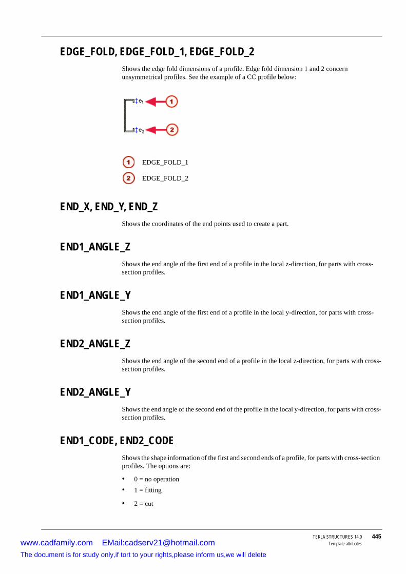
TEKLA STRUCTURES 14.0 445Template attributes
EDGE_FOLD, EDGE_FOLD_1, EDGE_FOLD_2Shows the edge fold dimensions of a profile. Edge fold dimension 1 and 2 concern unsymmetrical profiles. See the example of a CC profile below:
END_X, END_Y, END_ZShows the coordinates of the end points used to create a part.
END1_ANGLE_ZShows the end angle of the first end of a profile in the local z-direction, for parts with cross-section profiles.
END1_ANGLE_YShows the end angle of the first end of a profile in the local y-direction, for parts with cross-section profiles.
END2_ANGLE_ZShows the end angle of the second end of a profile in the local z-direction, for parts with cross-section profiles.
END2_ANGLE_YShows the end angle of the second end of the profile in the local y-direction, for parts with cross-section profiles.
END1_CODE, END2_CODEShows the shape information of the first and second ends of a profile, for parts with cross-section profiles. The options are:
• 0 = no operation • 1 = fitting
• 2 = cut
EDGE_FOLD_1
EDGE_FOLD_2
www.cadfamily.com EMail:[email protected] document is for study only,if tort to your rights,please inform us,we will delete

446 TEKLA STRUCTURES 14.0Template attributes
• 3 = fitting and cut
END1_SKEW, END2_SKEWShows 1 (INTEGER) if the corresponding end of a part has a skewed cut or fitting and 0 if the end is straight.
11.9 F
FATHER_IDShows the ID of the part that a reinforcement mesh belongs to.
FINISHShows the final properties of a part defined in the properties dialog box (for example, in the beam properties dialog box). For all other objects the field is blank.
FLANGE_LENGTH_BShows the total length of the lower flange of an I profile. Use when you need to show welded profiles as plates.
FLANGE_LENGTH_UShows the total length of the upper flange of an I profile. Use when you need to show welded profiles as plates.
FLANGE_SLOPE_RATIOShows the slope ratio of a flange.
FLANGE_THICKNESSShows the thickness of a flange.
FLANGE_THICKNESS_1, FLANGE_THICKNESS_2 Shows the flange thicknesses of unsymmetrical profiles, such as in unsymmetrical RCDL profile:
www.cadfamily.com EMail:[email protected] document is for study only,if tort to your rights,please inform us,we will delete

TEKLA STRUCTURES 14.0 447Template attributes
FLANGE_THICKNESS_BShows the thickness of the lower flange of an I profile. Use when you need to show welded profiles as plates.
FLANGE_THICKNESS_UShows the thickness of the upper flange of an I profile. Use when you need to show welded profiles as plates.
FLANGE_WIDTHShows the width of a flange.
FLANGE_WIDTH_1, FLANGE_WIDTH_2Shows the flange widths of unsymmetrical profiles.
FLANGE_WIDTH_BShows the width of the lower flange of an I profile. Use when you need to show welded profiles as plates.
FLANGE_WIDTH_UShows the width of the upper flange of an I profile. Use when you need to show welded profiles as plates.
FOLD_ANGLEShows the fold angle of a profile.
11.10G
GRADEShows the grade of the object. Use with BOLT, NUT, MESH, REBAR, and STUD content types.
GROUP_TYPEShows the group type of a reinforcing bar:
• Normal = 0• Tapered = 1
• Tapered 2 = 2
www.cadfamily.com EMail:[email protected] document is for study only,if tort to your rights,please inform us,we will delete

448 TEKLA STRUCTURES 14.0Template attributes
• Tapered curved = 3
• Tapered N = 4
• Spiral = 5
GUIDShows GUID, which is a globally unique identifier. For more information, see GUID.
11.11H
HEAD_DIAMETERShows the diameter of the stud head.
HEAD_THICKNESSShows the thickness (height) of the stud head.
HEIGHTShows the height of an object.
DRAWING content type:
• The height of the drawing.
ASSEMBLY content type:
• The height of the assembly main part for assemblies, parts, and bolts.
PART content type:
• The height of single-part or assembly drawings. Use in part and assembly lists.
HEIGHT_1 ... 4Shows the height dimensions of unsymmetrical profiles, such as in RCDX profile below:
HOLE_TOLERANCEOnly use in bolt lists. Shows the bolt tolerance. Shows a zero in all other lists.
www.cadfamily.com EMail:[email protected] document is for study only,if tort to your rights,please inform us,we will delete

TEKLA STRUCTURES 14.0 449Template attributes
HOOK_START, HOOK_ENDShows 1 if there is a hook at the start or end of a reinforcing bar, and 0 if there is no hook.
HOOK_START_ANGLE, HOOK_END_ANGLEShows the angle of the hook at the start or end of a reinforcing bar.
HOOK_START_LENGTH, HOOK_END_LENGTHShows the length of the straight part of the hook at the start or end of a reinforcing bar.
HOOK_START_RADIUS, HOOK_END_RADIUSShows the internal bending radius of the hook at the start or end of a reinforcing bar.
11.12I
INNER_DIAMETERShows the inner diameter of an object in the bolt catalog, for example, washers or nuts.
Use with BOLT, HOLE, NUT, and WASHER content types.
IDShows the identification number of an object. Use with all content types.
INFO1, INFO2Shows the corresponding values in the Project properties dialog box.
IS_POLYBEAMUse to check whether a part is a polybeam. The attribute returns 1 if the part is a polybeam, otherwise it returns 0.
11.13L
LASTThe last revision number of a drawing (as an integer).
www.cadfamily.com EMail:[email protected] document is for study only,if tort to your rights,please inform us,we will delete

450 TEKLA STRUCTURES 14.0Template attributes
LAST_MARKIn drawing templates this field shows the last revision mark. In DRAWING_REV lists, it also shows the entire revision history.
LAST_TEXT1...3In drawing templates this field shows the text for the last revision. In DRAWING_REV lists it also shows the revision history.
LENGTHShows the length of assemblies, parts, and bolts including cuts and fittings.
See also Polybeam length calculation.
LENGTH_GROSSShows the length of assemblies, parts, and bolts before cuts are made.
See also Polybeam length calculation.
LENGTH_MAXShows the maximum length of a reinforcing bar in a tapered bar group.
LENGTH_MINShows the minimum length of a reinforcing bar in a tapered bar group.
LONG_HOLE_XShows the value from the Slotted hole X field in the Bolt properties dialog box. See also DIAMETER_X.
LONG_HOLE_YShows the value from the Slotted hole Y field in the Bolt properties dialog box. See also DIAMETER_Y.
LOT_NUMBERShows the lot number to which the assembly belongs.
LOT_NAMEShows the name of the lot to which the assembly belongs.
www.cadfamily.com EMail:[email protected] document is for study only,if tort to your rights,please inform us,we will delete

TEKLA STRUCTURES 14.0 451Template attributes
11.14M
MAJOR_AXIS_LENGTH_1 ... 2Shows the major axis length dimensions of a tapered profile. Below d1 is the major axis length 1and d2 is the major axis length 2 in parametric profile EPD.
MARKIn drawing templates this field shows the last revision mark. In DRAWING_REV lists it also shows the revision history.
MATERIALShows the material name for parts. Shows the material of the assembly main part for assemblies. Shows the grade entered in the Bolt assembly catalog dialog box for bolts.
MATERIAL_TYPEShows the material type (STEEL, CONCRETE, etc) of assemblies or parts.
MESH_POSShows the position (prefix and running number) of a mesh.
MINOR_AXIS_LENGTH_1 ... 2Shows the minor axis length dimensions of a tapered profile. Below r1 is the minor axis length 1and r2 is the minor axis length 2 in parametric profile EPD.
MODELShows the name of the model.
MODEL_TOTALShows the number of similar objects in a model (i.e. those with the same position number).
www.cadfamily.com EMail:[email protected] document is for study only,if tort to your rights,please inform us,we will delete

452 TEKLA STRUCTURES 14.0Template attributes
MODULUS_OF_ELASTICITYShows the modulus of elasticity of a material from the material catalog.
MOMENT_OF_INERTIA_XShows the moment of inertia around the x-x reference axis of a cross section. Moment of inertia is also known as the second moment of area.
MOMENT_OF_INERTIA_YShows the moment of inertia around the y-y reference axis of a cross section. Moment of inertia is also known as the second moment of area.
MORTAR_VOLUMEShows the mortar volume used in surface treatment.
11.15N
NAME_BASEShows the drawing name.
NAME_FULLShows the name of a bolt defined in the bolt catalog, without the standard.
www.cadfamily.com EMail:[email protected] document is for study only,if tort to your rights,please inform us,we will delete
TEKLA STRUCTURES 14.0 453Template attributes
For example, in the case of the bolt highlighted in the above dialog box, the NAME_FULL field will show “BOLT20x130-2063”.
For objects other than bolts, the field shows a blank.
NAME_SHORTShows the name of the washer, bolt, nut or screw in a short format. See also NAME_FULL.
NEUTRAL_AXIS_LOCATION_ELASTIC_XShows the location of elastic neutral axis.
NEUTRAL_AXIS_LOCATION_ELASTIC_YShows the location of elastic neutral axis.
NEUTRAL_AXIS_LOCATION_PLASTIC_XShows the location of plastic neutral axis.
NEUTRAL_AXIS_LOCATION_PLASTIC_YShows the location of plastic neutral axis.
NORMALIZED_WARPING_CONSTANTShows the warping constant of a profile.
NUMBER#1, NUMBER #2NUMBER#1 shows the total number of objects on a list. Shows the total number of parts and bolts for one assembly for list types ASSEMBLY, ASSEMBLY_BOLT, ASSEMBLY_PART and ASSEMBLY_ALL, if the object is part of an assembly on the list.
NUMBER#2 shows the project number as text.
11.16O
OBJECTThe object field in the Project properties dialog box.
OBJECT_DESCRIPTIONShows the object type and ID. Below examples:
www.cadfamily.com EMail:[email protected] document is for study only,if tort to your rights,please inform us,we will delete

454 TEKLA STRUCTURES 14.0Template attributes
• PART 780*380 Id: 227• ASSEMBLY Id: 144
• MESH Id: 946
OBJECT_LOCKEDShows the status of the user-defined attribute Locked.
For more information on this attribute, see Locking objects (p. 76).
OBJECT_TYPEThe type of object. The message files contain the translations of these strings (numbers 576 - 587).
The object types are:
• POINT• PART
• JOINT
• FITTING
• SCREW
• ANTI-MATERIAL
• CUT
• WELDING
• ASSEMBLY
• DRAWING
• PROJECT
• OBJECT
OWNERShows the object owner in format domain/user.
11.17P
PAGEThe current page number.
PART_POSThe position number of parts. Shows a blank cell for all other objects.
www.cadfamily.com EMail:[email protected] document is for study only,if tort to your rights,please inform us,we will delete

TEKLA STRUCTURES 14.0 455Template attributes
Shows the mark of assembly main part for assemblies, parts, and bolts. For all other objects the field is blank.
PART_PREFIXShows the part prefix, defined in the part properties dialog box.
For more information on numbering series, see Defining numbers to be used for parts.
PART_SERIAL_NUMBERShows the part number without the prefix and separator.
PCSShows the number of bars in a reinforcing bar group.
PHASEThe number of the phase to which the object belongs.
To show the phase name, use the PHASE.NAME field.
PLASTIC_MODULUS_XShows the plastic modulus of x-x reference axis of a cross section. Also known as the first moment of area.
PLASTIC_MODULUS_Y Shows the plastic modulus of y-y reference axis of a cross section. Also known as the first moment of area.
PLATE_DENSITYShows the material density of a plate (kg/m3).
PLATE_THICKNESSShows the thickness of a plate (mm).
PLOTFILEShows the name of the drawing plot file. Only for use in drawing tables and drawing reports.
See also XS_DRAWING_PLOT_FILE_NAME (p. 331)
www.cadfamily.com EMail:[email protected] document is for study only,if tort to your rights,please inform us,we will delete

456 TEKLA STRUCTURES 14.0Template attributes
POISSONS_RATIOShows the Poisson’s ratio (analysis property) of material.
POLAR_RADIUS_OF_GYRATIONShows the polar radius of gyration (analysis property) of a profile.
PRELIM_MARKShows the user-defined attribute Prelim mark.
For more information on preliminary marks, see Tools > Numbering > Preliminary marks.
PROFILEShows the part profile name, or the main part profile name in an assembly or cast unit. You can also show profile attributes in templates and reports:
In the Template editor, open the Select attribute dialog box and select PROFILE.* attributes for the selected content type:
For example, MAINPART.PROFILE.HEIGHT with ASSEMBLY content type, shows the height of the main part profile in the assembly.
www.cadfamily.com EMail:[email protected] document is for study only,if tort to your rights,please inform us,we will delete

TEKLA STRUCTURES 14.0 457Template attributes
PROFILE_DENSITYShows the profile density of material (kg/m3).
PROFILE_TYPEThe profile type of the part. The default types in Tekla Structures conform to DSTV-NC documentation. They are defined (message numbers 588 - 599) in the message file by_number.ail in the folder ..\TeklaStructures\*version*\messages. The table below shows the relationship between messages, profiles in Tekla Structures, and the DSTV-NC profile types defined in messages.
PROFILE_WEIGHTThe weight of a part. For profiles Tekla Structures calculates the weight using the length and weight/m values in the profile catalog. If the weight/m is not defined in the profile catalog, this field works in the same way as WEIGHT_NET, but uses the plate density value (Property weight for plates) from the material catalog instead of profile density.
PROFILE_WEIGHT_NETThe net weight of a part. For profiles Tekla Structures calculates the weight using the length and weight/m values in the profile catalog. Line cuts do not affect the length value, which is calculated using the fitted centerline. For all other objects this field works in the same way as WEIGHT_NET.
Tekla Structures profiles Message number
Shows DSTV-NC profile type
I-profiles 589 IL-profiles 589 LU-profiles 591 UPlates 592 BRound tubes 593 RURound bars 594 ROSquare tubes 595 MCC-profiles 596 CT-profiles 597 TPolygon plates 598 BFolded plates 599 BZ-profiles and all the other types of profile
590 Z
www.cadfamily.com EMail:[email protected] document is for study only,if tort to your rights,please inform us,we will delete

458 TEKLA STRUCTURES 14.0Template attributes
11.18R
RADIUS_OF_GYRATION_XShows the radius of gyration x (analysis property) of a profile.
RADIUS_OF_GYRATION_YShows the radius of gyration y (analysis property) of a profile.
REBAR_POSShows the position (prefix and the running number) of reinforcing bars.
REFERENCE_MODELLists reference models in reports.
See also Reference models (p. 271)
REFERENCE_MODEL_OBJECTLists reference models objects in reports.
See also Reference model objects (p. 276)
ROUNDING_RADIUS, ROUNDING_RADIUS_1 ... 2Shows different rounding radii of profiles. Below as an example rounding radius 1 and 2 for a specific I profile:
ROW_IN_PAGEProduces an incremental number starting from 1 at the beginning of each new page. Use in reports and templates.
Example Can be used together with the PAGE field to include page or row information in the drawing template. Set Type to Text and enter the following field definition in the Text field properties:
=%PAGE% %/% %ROW_IN_PAGE%
www.cadfamily.com EMail:[email protected] document is for study only,if tort to your rights,please inform us,we will delete

TEKLA STRUCTURES 14.0 459Template attributes
11.19S
SCALE1...5Use these fields to show the different scales of drawing views. Decimal values are rounded to the nearest integer. Only for use in drawing tables.
SECTION_MODULUS_X, SECTION_MODULUS_YShows section modulus (analysis property) of a profile.
SHAPEShows the environment-specific bending type of a reinforcing bar.
SHAPE_INTERNALShows the internal bending type of Tekla Structures for a reinforcing bar, for example, 2_1.
SHEAR_CENTER_LOCATIONShows the shear center location (analysis property) of a profile.
SIMILAR_TO_MAIN_PARTReturns 1 if the position number of the given part is the same as the position number of the main part in the assembly.
To show a main part of an assembly on top of part lists:
1. In the Template Editor, add value field SIMILAR_TO_MAIN_PART to PART row.2. Set the Order to Descending and (if needed) hide the field in output, in the Value Field
Properties dialog box.
3. Drag the SIMILAR_TO_MAIN_PART field to be first in sort order in the Content browser.
SITE_WORKSHOPFor bolts this field shows the assembly type information in a string (Site or Shop). The message files (466 and 467) contain translations of these strings.
For studs this field shows the assembly type information in a string (Site or Shop).
SIZEShows the size of the drawing (e.g. 210x297). Only for use in drawing templates and drawing reports.
www.cadfamily.com EMail:[email protected] document is for study only,if tort to your rights,please inform us,we will delete

460 TEKLA STRUCTURES 14.0Template attributes
SORT_OF_E_x_Cw_PER_G_x_JShows sqrt(ECw/GJ) analysis property of a profile.
SUPPLEMENT_PART_WEIGHTShows the weight of supplementary parts. SUPPLEMENT_PART_WEIGHT = the weight of the whole assembly less the weight of the main part.
See also WEIGHT.
START_XShows the coordinates of the creation points of parts.
START_YSee START_X.
START_ZSee START_X.
STATICAL_MOMENT_QfShows the statical moment of the flange.
STATICAL_MOMENT_QwShows the statical moment of the web.
STIFFENER_DIMENSIONShows the stiffener dimension of a profile. See also STIFFENER_DIMENSION_1 ... 3.
STIFFENER_DIMENSION_1 ... 3Shows the stiffener dimensions of a profile. Below f1 is stiffener dimension 1, f2 is stiffener dimension 2, and f3 is stiffener dimension 3 in parametric profile EZ.
www.cadfamily.com EMail:[email protected] document is for study only,if tort to your rights,please inform us,we will delete

TEKLA STRUCTURES 14.0 461Template attributes
STRAND_DEBONDED_STRANDS_1...5Shows a list of debonded strands. Strand numbers are separated by spaces.
STRAND_DEBONDED_STRANDS_1 corresponds to row 1 on the Debonding tab in the Strand Pattern Properties dialog box, STRAND_DEBONDED_STRANDS_2 to row 2, and so on.
STRAND_DEBOND_LEN_FROM_END_1...5Shows the debonding length from the end of the strands.
STRAND_DEBOND_LEN_FROM_END_1 corresponds to row 1 on the Debonding tab in the Strand Pattern Properties dialog box, STRAND_DEBOND_LEN_FROM_END_2 to row 2, and so on.
STRAND_DEBOND_LEN_FROM_START_1...5Shows the debonding length from the start of the strands.
STRAND_DEBOND_LEN_FROM_START_1 corresponds to row 1 on the Debonding tab in the Strand Pattern Properties dialog box, STRAND_DEBOND_LEN_FROM_START_2 to row 2, and so on.
STRAND_DEBOND_LEN_MIDDLE_TO_END_1...5Shows the debonding length from the middle to the end of the strands.
STRAND_DEBOND_LEN_MIDDLE_TO_END_1 corresponds to row 1 on the Debonding tab in the Strand Pattern Properties dialog box, STRAND_DEBOND_LEN_MIDDLE_TO_END_2 to row 2, and so on.
STRAND_DEBOND_LEN_MIDDLE_TO_START_1...5Shows the debonding length from the middle to the start of the strands.
STRAND_DEBOND_LEN_MIDDLE_TO_START_1 corresponds to row 1 on the Debonding tab in the Strand Pattern Properties dialog box, STRAND_DEBOND_LEN_MIDDLE_TO_START_2 to row 2, and so on.
STRAND_N_PATTERNShows the number of different cross-sections in a strand pattern.
STRAND_N_STRANDShows the number of strands.
STRAND_POSShows the position (prefix and running number) of a strand.
www.cadfamily.com EMail:[email protected] document is for study only,if tort to your rights,please inform us,we will delete

462 TEKLA STRUCTURES 14.0Template attributes
STRAND_PULL_FORCEShows the pull force of a strand.
STRAND_UNBONDEDShows the sequence numbers of debonded strands, seprated by spaces or commas.
SUBTYPEShows the subtype of a profile.
SURFACING_NAMEShows the name of a sufrace treatment.
11.20T
TANGENT_OF_PRINCIPAL_AXIS_ANGLEShows the tangent of principal axis angle (analysis property) of a profile.
TEXT1...3In drawing templates this field shows the text for the last revision. In DRAWING_REV lists it also shows the revision history.
THERMAL_DILATATIONShows the thermal dilatation coefficient of material.
THREAD_IN_MATERIALShows 1 if the thread of the screw can be inside the material to be connected and 0 if not.
TILE_NUMBERShows the number of tiles used in surface treatment (approximate value).
TILE_VOLUMEShows the volume of tiles used in surface treatment, without the mortar volume. See also MORTAR_VOLUME.
www.cadfamily.com EMail:[email protected] document is for study only,if tort to your rights,please inform us,we will delete

TEKLA STRUCTURES 14.0 463Template attributes
TIMEShows the current time (hh:mm:ss).
TITLEShows the user-defined drawing name. Can also be used for parts and assemblies. For example, you could create a report of assemblies listing which assembly drawings had been created.
TITLE1...3In reports this field shows the user-defined titles entered in the Report dialog box. In drawing templates this field shows the drawing attributes.
TOP_LEVELShows the bottom level of a single part, or a cast unit, or an assembly, or a part of a connection.
You can use this attribute as a user-defined attribute also in part marks and associative notes.
TOP_LEVEL_UNFORMATTEDShows the bottom level of a single part, or a cast unit, or an assembly, or a part of a connection.
You can use this attribute as a user-defined attribute also in part marks and associative notes.
TORSIONAL_CONSTANTShows the torsional constant (analysis property) of a profile.
TYPEShows the object type or standard:
This attribute returns the value as text, so you cannot use formulae with this attribute. Use TOP_LEVEL_UNFORMATTED instead.
Content type Description
BOLT Shows the bolts standard as it appears in the Bolt assembly catalog dialog box (for example, 7968). For all other objects the field is blank.
DRAWING Shows the drawing type: A, W, C, G or M.MESH Shows the mesh standard.NUT Shows the nut standard.
www.cadfamily.com EMail:[email protected] document is for study only,if tort to your rights,please inform us,we will delete

464 TEKLA STRUCTURES 14.0Template attributes
TYPE1For bolts this field shows the bolt type as the type of each possible bolt part that appears in the Bolt assembly catalog dialog box (e.g. 7968/2041/2041/2041/2067/2067). For objects other than bolts the field is blank.
TYPE2For bolts this field shows the bolt type as the numbers of existing bolt parts (e.g. 10021). For objects other than bolts the field is blank.
TYPE3The same as BOLT_TYPE2, but shows X for existing and o for nonexistent bolt parts (for example, XooXX). For objects other than bolts the field shows a blank.
TYPE4The same as BOLT_TYPE1 but only the existing components are shown in the string.
11.21U
USERFIELD_1 ... _8Shows the value of the user-defined attribute User field 1, User field 2 etc.
See also For more information on the user-defined attributes in templates and reports, see User-defined attributes in templates (p. 426).
For more information on user-defined attributes, see User-defined attributes and User-defined attributes in drawings.
11.22VTopics VOLUME
VOLUME_GROSS
VOLUME_NET
SURFACING Surface treatment type in the Surface Treatment Properties dialog box.
WASHER Shows the standard of the washer.
Content type Description
www.cadfamily.com EMail:[email protected] document is for study only,if tort to your rights,please inform us,we will delete

TEKLA STRUCTURES 14.0 465Template attributes
VOLUMEShows the object volume, for example, the volume of an assembly or of a cast unit. Takes holes and cuts into account.
VOLUME_GROSSShows the object gross volume. Does not take into account holes and cuts.
VOLUME_NETShows the object volume taking into account holes and cuts.
11.23W
WARPING_CONSTANTShows the warping constant (analysis property) of a profile.
WARPING_STATICAL_MOMENTShows the warping statical moment (analysis property) of a profile.
WEB_HEIGHTSee WEB_WIDTH.
WEB_LENGTHThe gross length of the web of an I profile. Use to show welded profiles as plates.
WEB_THICKNESSThe thickness of the web of an I profile. Use to show welded profiles as plates.
WEB_THICKNESS_1, WEB_THICKNESS_2The additional thickness values of the web of a profile.
WEB_WIDTHThe width of the web of an I profile. Use to show welded profiles as plates.
www.cadfamily.com EMail:[email protected] document is for study only,if tort to your rights,please inform us,we will delete

466 TEKLA STRUCTURES 14.0Template attributes
WEIGHTShows the weight of the object. The calculation formula depends on the object type:
• For parts with cross-sections defined in the profile catalog, the weight is calculated from the cross section area in the profile catalog), length (LENGTH) and density of material (property weight for profiles in the material catalog). The result is the same as calculating WEIGHT_GROSS.
• For other profiles with no cross sections defined (typically parametric profiles), shows the net weight calculated using the profile volume and density of material. Fittings, cuts, weld preparations, and part adds affect volume calculation.
• For assemblies, shows the sum of the part weights for each assembly.
• For bolts, shows the weight of the entire bolt assembly (including washers and nut) in grams.
WEIGHT_GROSSShows the gross weight, which is the total weight of material needed to fabricate the part. The calculation formula depends on the part:
• If the part has cross-sections defined in the profile catalog, the weight is calculated from part length (LENGTH), the cross section area in the profile catalog, and the density of material.
• If the part is a folded or contour plate without a cross section area, the weight is calculated from plate overall height, overall length and density of material (property weight for plates in the material catalog).
• For other profiles without cross sections (typically parametric profiles), the gross weight is calculated the same way as the WEIGHT_NET, but cuts are not taken into account and the plate density value is used instead of profile density.
• For assemblies, shows the combined gross weight of parts included in an assembly. For bolts it shows the bolt weight.
WEIGHT_MShows the property weight of a profile (defined in the material catalog). For parametric profiles, shows the weight of the profile divided by the length. For standard profiles, shows the Weight per unit length from the Analysis properties in the profile catalog.
WEIGHT_MAXShows the maximum weight of a single reinforcing bar or strand in a tapered bar group.
WEIGHT_MINShows the minimum weight of a single reinforcing bar or strand in a tapered bar group.
WEIGHT_NETShows the weight of the fabricated part, assembly or cast unit. The calculation formula depends on the object:
www.cadfamily.com EMail:[email protected] document is for study only,if tort to your rights,please inform us,we will delete

TEKLA STRUCTURES 14.0 467Template attributes
• For parts, returns the net weight, which is the actual weight of the fabricated part. • For bolts, returns the bolt weight, and for other objects a zero.
• For assemblies, returns the sum of part weights.
The calculation is based on part volume and density of material. The density value used in the calculation depends on the profile cross-sections:
• If cross-section are defined in the profile catalog, density is the Property weight of profiles in the material catalog.
• If there are no cross-sections, density is the Property weight of plates in the material catalog.
WEIGHT_PER_UNIT_LENGTHShows the weight per unit length (analysis property) of a profile.
WEIGHT_TOTALShows the total weight of all reinforcing bars or of all strands in a reinforcing bar group.
WELD_ANGLE1, WELD_ANGLE2Shows weld angle for welds above and below line.
WELD_ASSEMBLYTYPEShows the assembly type of a weld (Site or Shop). Only use in welding lists.
WELD_DEFAULTShows the default weld size according to the drawing attributes. Only use in drawing tables.
WELD_FATHER_CODEShows the connection running number of the connection where the weld is located. The field is blank if the weld is not next to a connection. Use only in welding lists.
WELD_FATHER_NUMBERShows the connection number of the connection where the weld is located. The field is blank if the weld is not next to a connection. Use only in welding lists.
WELD_FILLTYPE1, WELD_FILLTYPE2Shows the weld contour (None, Flush, Convex, Concave) for welds above and below line.
WELD_FINISH1, WELD_FINISH2Shows the weld finish for welds above and below line.
www.cadfamily.com EMail:[email protected] document is for study only,if tort to your rights,please inform us,we will delete
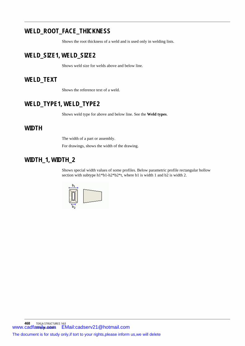
468 TEKLA STRUCTURES 14.0Template attributes
WELD_ROOT_FACE_THICKNESSShows the root thickness of a weld and is used only in welding lists.
WELD_SIZE1, WELD_SIZE2Shows weld size for welds above and below line.
WELD_TEXTShows the reference text of a weld.
WELD_TYPE1, WELD_TYPE2Shows weld type for above and below line. See the Weld types.
WIDTHThe width of a part or assembly.
For drawings, shows the width of the drawing.
WIDTH_1, WIDTH_2Shows special width values of some profiles. Below parametric profile rectangular hollow section with subtype h1*b1-h2*b2*t, where b1 is width 1 and b2 is width 2.
www.cadfamily.com EMail:[email protected] document is for study only,if tort to your rights,please inform us,we will delete

TEKLA STRUCTURES 14.0 469Reinforcing bar bending types
12 Reinforcing bar bending types
Tekla Structures recognizes different reinforcing bar bending shapes and assigns bending type identifiers to them. The table below lists these reinforcing bar bending types.
If Tekla Structures does not recognize the shape of a reinforcing bar, it assigns the UNKNOWN bending type to it.
The bending type identifiers in the table below are internal, hard-coded types of Tekla Structures. The leg dimensions (D1, D2, etc.) and bending angles (A1, A2, etc.) of reinforcing bars are internal dimensions and angles. You can map internal types, for example, to country- or project-specific types, and internal dimensions and angles to specific template attributes. You do this in the rebar_schedule_config.inp file. See Reinforcement in templates (p. 490).
The magenta points in the images represent the points you pick in the model when you create reinforcing bars.
Type Image
1
2_1
Requires standard bending radius.2_2
Non-standard bending radius.
www.cadfamily.com EMail:[email protected] document is for study only,if tort to your rights,please inform us,we will delete
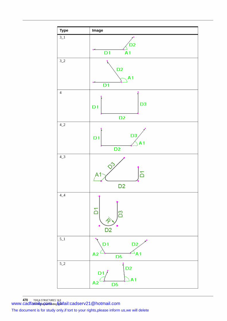
470 TEKLA STRUCTURES 14.0Reinforcing bar bending types
3_1
3_2
4
4_2
4_3
4_4
5_1
5_2
Type Image
www.cadfamily.com EMail:[email protected] document is for study only,if tort to your rights,please inform us,we will delete

TEKLA STRUCTURES 14.0 471Reinforcing bar bending types
5_3
6_1
6_2
7
8
8_29
Requires 180 degree hook.10
Type Image
www.cadfamily.com EMail:[email protected] document is for study only,if tort to your rights,please inform us,we will delete

472 TEKLA STRUCTURES 14.0Reinforcing bar bending types
11
12
13
Can also be modeled using hooks at both ends (i.e. model D1 and D5 using 90 degree hooks).
14
Requires hooks at both ends.14_2
Type Image
www.cadfamily.com EMail:[email protected] document is for study only,if tort to your rights,please inform us,we will delete

TEKLA STRUCTURES 14.0 473Reinforcing bar bending types
14_3
14_4
Requires 90 degree hooks at both ends.14_5
Recognized if XS_REBAR_RECOGNITION_HOOKS_CONSIDERATION is set to FALSE.
15
Requires hooks at both ends.16_1
Type Image
www.cadfamily.com EMail:[email protected] document is for study only,if tort to your rights,please inform us,we will delete

474 TEKLA STRUCTURES 14.0Reinforcing bar bending types
16_2
17
18
19
20_1
20_2
Type Image
www.cadfamily.com EMail:[email protected] document is for study only,if tort to your rights,please inform us,we will delete

TEKLA STRUCTURES 14.0 475Reinforcing bar bending types
21
22
23
24
25
26
Requires 180 degree hooks at both ends.27
Requires 90 degree hooks at both ends.
Type Image
www.cadfamily.com EMail:[email protected] document is for study only,if tort to your rights,please inform us,we will delete

476 TEKLA STRUCTURES 14.0Reinforcing bar bending types
28
Requires 180 degree hooks at both ends.29
Requires 90 degree hooks at both ends.29_2
29_3
29_4
29_5
Type Image
www.cadfamily.com EMail:[email protected] document is for study only,if tort to your rights,please inform us,we will delete

TEKLA STRUCTURES 14.0 477Reinforcing bar bending types
30
Requires 180 degree hooks at both ends.31
Requires 90 degree hooks at both ends.32
Requires 180 degree hooks at both ends.33
Requires 90 degree hooks at both ends.34
35
Requires 180 degree hook.
Type Image
www.cadfamily.com EMail:[email protected] document is for study only,if tort to your rights,please inform us,we will delete

478 TEKLA STRUCTURES 14.0Reinforcing bar bending types
36
Requires 180 degree hook.36_2
Can also be modeled using hooks at both ends.36_3
Can also be modeled using hooks at both ends.37
Requires 180 degree hook.38
Requires 180 degree hook at one end and 90 degree hook at the other end.
38_2
Type Image
www.cadfamily.com EMail:[email protected] document is for study only,if tort to your rights,please inform us,we will delete

TEKLA STRUCTURES 14.0 479Reinforcing bar bending types
39
40
Requires 180 degree hooks at both ends.41
Requires 90 degree hooks at both ends.42
Requires 180 degree hooks at both ends.43
43_2
Type Image
www.cadfamily.com EMail:[email protected] document is for study only,if tort to your rights,please inform us,we will delete

480 TEKLA STRUCTURES 14.0Reinforcing bar bending types
44
Requires hooks at both ends.44_2
Requires 180 degree hooks at both ends.45
Requires hooks at both ends.45_2
Requires 180 hooks at both ends.46
Requires hooks at both ends.
Type Image
www.cadfamily.com EMail:[email protected] document is for study only,if tort to your rights,please inform us,we will delete

TEKLA STRUCTURES 14.0 481Reinforcing bar bending types
47
Requires 90 degree hooks at both ends.48
Requires hooks at both ends.48_2
Requires hooks at both ends.48_3
49
Type Image
www.cadfamily.com EMail:[email protected] document is for study only,if tort to your rights,please inform us,we will delete

482 TEKLA STRUCTURES 14.0Reinforcing bar bending types
49_2
50
Requires hooks at both ends.51
Requires 90 degree hooks at both ends.52
Requires hooks at both ends.53
Requires hooks at both ends.54
Requires hooks at both ends.
Type Image
www.cadfamily.com EMail:[email protected] document is for study only,if tort to your rights,please inform us,we will delete

TEKLA STRUCTURES 14.0 483Reinforcing bar bending types
55
56
57
58
59
60
61
Requires hooks at both ends.
Type Image
www.cadfamily.com EMail:[email protected] document is for study only,if tort to your rights,please inform us,we will delete

484 TEKLA STRUCTURES 14.0Reinforcing bar bending types
61_2
Recognized if XS_REBAR_RECOGNITION_HOOKS_CONSIDERATION is set to FALSE.
61_3
Requires hooks at both ends.62
Requires hook.63
Requires hook.64
Requires hooks at both ends.
Type Image
www.cadfamily.com EMail:[email protected] document is for study only,if tort to your rights,please inform us,we will delete

TEKLA STRUCTURES 14.0 485Reinforcing bar bending types
64_2
Recognized if XS_REBAR_RECOGNITION_HOOKS_CONSIDERATION is set to FALSE.
65
Requires hooks at both ends.65_2
Recognized if XS_REBAR_RECOGNITION_HOOKS_CONSIDERATION is set to FALSE.
66
Type Image
www.cadfamily.com EMail:[email protected] document is for study only,if tort to your rights,please inform us,we will delete

486 TEKLA STRUCTURES 14.0Reinforcing bar bending types
67
67_2
68
69_1
69_2
70_1
Type Image
www.cadfamily.com EMail:[email protected] document is for study only,if tort to your rights,please inform us,we will delete

TEKLA STRUCTURES 14.0 487Reinforcing bar bending types
70_2
71
72
73_1
73_2
73_3
Type Image
www.cadfamily.com EMail:[email protected] document is for study only,if tort to your rights,please inform us,we will delete

488 TEKLA STRUCTURES 14.0Reinforcing bar bending types
74
75_1
75_2
76
77
Type Image
www.cadfamily.com EMail:[email protected] document is for study only,if tort to your rights,please inform us,we will delete

TEKLA STRUCTURES 14.0 489Reinforcing bar bending types
78
79_1
79_2
80
UNKNOWN For example:
Type Image
www.cadfamily.com EMail:[email protected] document is for study only,if tort to your rights,please inform us,we will delete

490 TEKLA STRUCTURES 14.0Reinforcing bar bending types
12.1 Reinforcement in templatesAudience This topic is aimed at Tekla Structures users who need to localize reinforcing bar bending types
or to create templates for reinforcing bar bending schedules.
Reinforcement templates
You can show dimensions, bending angles, and bending types of reinforcing bars in drawings and reports by including reinforcement-specific attributes, such as DIM_A, ANG_S, SHAPE, and SHAPE_INTERNAL, in template fields. For more information on creating templates, see the Template Editor (TplEd) online help.
Mapping dimensions
Use the rebar_schedule_config.inp file in the ..\environments\*your_environment*\system folder to map:
• Tekla Structures internal reinforcing bar dimensions and angles with specific template attributes
• Tekla Structures internal reinforcing bar bending types with specific bending types
These mappings are environment-specific by default. You can modify them to suit your company or project needs.
You can use equations, functions, and if statements to calculate the dimensions and angles you need to show.
Use any standard text editor (for example, Notepad) to edit the rebar_schedule_config.inp file.
Examples The following example of the rebar_schedule_config.inp file maps the internal bending type 5_1 to the bending type identifier E, and the leg dimensions and bending angles to specific template attributes:
With this mapping, the internal bending type 6_2 becomes XY, and the template attributes DIM_B and DIM_C will show the horizontal and vertical dimensions of the second leg D2, and DIM_E and DIM_F the horizontal and vertical dimensions of the fourth leg D4:
rebar_schedule_config.inp (Example 1)
BEND_TYPE_5_1[1]="E"BEND_TYPE_5_1[2]="DIM_A=D1"BEND_TYPE_5_1[3]="DIM_B=D5"BEND_TYPE_5_1[4]="DIM_C=D2"BEND_TYPE_5_1[5]="DIM_TD=TD"BEND_TYPE_5_1[6]="ANG_U=A1"BEND_TYPE_5_1[7]="ANG_V=A2"
rebar_schedule_config.inp (Example 2)
BEND_TYPE_6_2[1]="XY"BEND_TYPE_6_2[2]="DIM_A=D1"BEND_TYPE_6_2[3]="DIM_B=D2*COS(A2*PI/180)"BEND_TYPE_6_2[4]="DIM_C=D2*SIN(A2*PI/180)"BEND_TYPE_6_2[5]="DIM_D=D3"BEND_TYPE_6_2[6]="DIM_E=D4*COS(A1*PI/180)"BEND_TYPE_6_2[7]="DIM_F=D4*SIN(A1*PI/180)"BEND_TYPE_6_2[8]="DIM_G=D5"BEND_TYPE_6_2[9]="DIM_TD=TD"
www.cadfamily.com EMail:[email protected] document is for study only,if tort to your rights,please inform us,we will delete
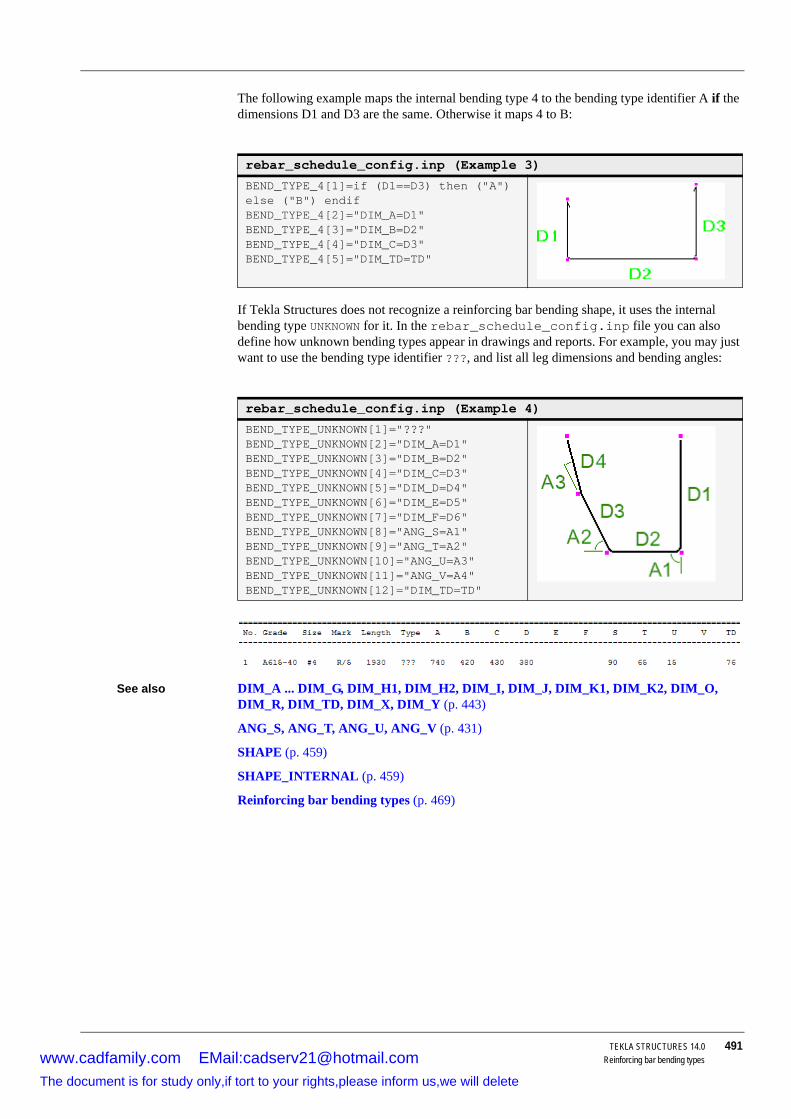
TEKLA STRUCTURES 14.0 491Reinforcing bar bending types
The following example maps the internal bending type 4 to the bending type identifier A if the dimensions D1 and D3 are the same. Otherwise it maps 4 to B:
If Tekla Structures does not recognize a reinforcing bar bending shape, it uses the internal bending type UNKNOWN for it. In the rebar_schedule_config.inp file you can also define how unknown bending types appear in drawings and reports. For example, you may just want to use the bending type identifier ???, and list all leg dimensions and bending angles:
See also DIM_A ... DIM_G, DIM_H1, DIM_H2, DIM_I, DIM_J, DIM_K1, DIM_K2, DIM_O, DIM_R, DIM_TD, DIM_X, DIM_Y (p. 443)
ANG_S, ANG_T, ANG_U, ANG_V (p. 431)
SHAPE (p. 459)
SHAPE_INTERNAL (p. 459)
Reinforcing bar bending types (p. 469)
rebar_schedule_config.inp (Example 3)
BEND_TYPE_4[1]=if (D1==D3) then ("A") else ("B") endifBEND_TYPE_4[2]="DIM_A=D1"BEND_TYPE_4[3]="DIM_B=D2"BEND_TYPE_4[4]="DIM_C=D3"BEND_TYPE_4[5]="DIM_TD=TD"
rebar_schedule_config.inp (Example 4)
BEND_TYPE_UNKNOWN[1]="???"BEND_TYPE_UNKNOWN[2]="DIM_A=D1"BEND_TYPE_UNKNOWN[3]="DIM_B=D2"BEND_TYPE_UNKNOWN[4]="DIM_C=D3"BEND_TYPE_UNKNOWN[5]="DIM_D=D4"BEND_TYPE_UNKNOWN[6]="DIM_E=D5"BEND_TYPE_UNKNOWN[7]="DIM_F=D6"BEND_TYPE_UNKNOWN[8]="ANG_S=A1"BEND_TYPE_UNKNOWN[9]="ANG_T=A2"BEND_TYPE_UNKNOWN[10]="ANG_U=A3"BEND_TYPE_UNKNOWN[11]="ANG_V=A4"BEND_TYPE_UNKNOWN[12]="DIM_TD=TD"
www.cadfamily.com EMail:[email protected] document is for study only,if tort to your rights,please inform us,we will delete

TEKLA STRUCTURES 14.0 492
Index
aaccess rights ................................................................ 75adding properties.......................................................... 98adding user-defined attributes...................................... 98advanced line type and layer conversion ................... 268
defining your own line type mappingsline ............................................................... 268
advanced options ....................................................... 285ail files .......................................................................... 89analysis models (CIS) ........................................199, 224anti-spyware ................................................................. 45applications ................................................................ 296ASCII
exporting ............................................................. 234importing .....................................................206, 211
assdb.db....................................................................... 91asterisk ....................................................................... 308AutoConnection.......................................................... 151
changing a connection ........................................ 155connecting built-in members ............................... 313restrictions........................................................... 153rules .................................................................... 159setup ................................................................... 152tolerance ............................................................. 300UDL ..................................................................... 300when to use........................................................... 47
AutoDefaults............................................................... 151rules .................................................................... 159setup ................................................................... 156when to use........................................................... 47
AutoDrawings ............................................................. 113AutoDrawings wizard files
creating ............................................................... 106automating detailing ..................................................... 45Autosave ...................................................................... 48
error....................................................................... 50file location ............................................................ 49folder ................................................................... 301keeping files .......................................................... 50setting interval ....................................................... 49usernames ............................................................ 50
bbackground color ........................................................301bak files ........................................................................95basic view
height...................................................................303horizontal position ...............................................303vertical position....................................................303width ....................................................................303
batch file .......................................................................79beam length................................................................174bin files .........................................................................90bolt assemblies...........................................................134bolt assembly catalog .................................................134
viewing or modifying............................................137bolt catalog .................................................................134
exporting..............................................................141importing..............................................................141importing part of ..................................................144merging ...............................................................141modifying .............................................................135saving ..................................................................137upgrading to new version ....................................141viewing ................................................................135
bolt length calculation .................................................146bolt length rounding ....................................................304bolt mark contents
size ..................................................... 305, 385, 391bolts
catalog.................................................................134importing catalog .................................................141importing part of catalog......................................144length...................................................................146upgrading catalog to new version........................141
Busimporting..............................................................205
BVBS export ...............................................................240by_number.ail .............................................................102
www.cadfamily.com EMail:[email protected] document is for study only,if tort to your rights,please inform us,we will delete

TEKLA STRUCTURES 14.0 493
cc/c format.................................................................... 307CAD
exporting models................................................. 229import file types ................................................... 200importing ............................................................. 200
Calma .................................................................201, 229catalog export files ..................................................... 143
editing.................................................................. 144catalogs ........................................................................ 42
a closer look at the export file ............................. 143bolt and assembly introduction............................ 134common features and processes ........................ 115difference between Update and OK .................... 117editing export files ............................................... 144for advanced users.............................................. 143material introduction............................................ 130overview .............................................................. 115profile introduction............................................... 117reinforcing bar introduction.................................. 142rules in profile catalog ......................................... 118saving a modified catalog.................................... 116units used in import and export ........................... 145which catalog am I using?................................... 116
chamferaccuracy......................................................307, 315length accuracy ................................................... 307
change symbol ........................................................... 346changing the language of the user interface .............. 103changing the NC folder............................................... 173changing user-defined attributes .................................. 99checking multi-user databases..................................... 75CIMsteel
database name ................................................... 310database path ..................................................... 310exporting analysis models................................... 224exporting manufacturing models ......................... 226express file .......................................................... 310password.....................................................310, 338
CISexporting analysis models................................... 224exporting manufacturing models ......................... 226importing ............................................................. 199
clash checkcolor .................................................................... 311
cloudarc width.............................................................. 296
CNC............................................................................ 167cnv files ................................................................90, 192
colorbackground..........................................................301
columnvertically in drawings ...........................................407
Combining properties .................................................162component description files ..........................................86connecting side symbol ..............................................313Connection Browser ...................................................155connection properties files ..........................................157
accessing ............................................................157saving ..................................................................157
content type ................................................................423conversion files
CIS examples ......................................................227creating................................................................192in..........................................................................192locating ................................................................193samples ...............................................................193troubleshooting....................................................193where to save ......................................................193
copyingmulti-user models ..................................................64
creatingconversion files....................................................192cross sections......................................................123customer-specific initializarion...............................83NC files ................................................................174Peddimat files ......................................................176shortcuts ................................................................83standard files .......................................................106
cross sectionscreating................................................................123deleting from catalog ...........................................125modifying .............................................................124
customizing...................................................................98AutoDrawings wizard files ...................................106connections ...........................................................46creating standard files .........................................106interface.................................................................51message files ......................................................102modeling................................................................46other properties files ............................................106parametric profiles ...............................................104properties ..............................................................98toolbars..................................................................51user-defined fields in templates...........................100
www.cadfamily.com EMail:[email protected] document is for study only,if tort to your rights,please inform us,we will delete
494 TEKLA STRUCTURES 14.0
ddat files .........................................................................86data files and modeling tools ........................................87db1................................................................................95db2................................................................................95defaults.zxt......................................................... 156, 158deleting
cross sections from catalog .................................125material grades from catalog ...............................133unnecessary ..........................................................75
detailingautomating.............................................................45
dg files ..........................................................................96DGN............................................................................271
exporting 3D ........................................................221supported objects ................................................277
diameter prefix ............................................................304dimension point change symbol .................................346dimensions
extension origin offset..........................................319disabling variables ........................................................81display adaptor
optimizing performance .........................................54dproc files .....................................................................92drawing files..................................................................73
deleting unnecessary.............................................75drawing position on screen.........................................333drawings
exporting..............................................................266in multi-user mode .................................................73
DSTV ................................................................. 174, 202converting to DXF................................................176exporting..............................................................223importing..............................................................203
DSTV connection properties.........................................89DSTV.bat ....................................................................176dstv.lis...........................................................................89DWG...........................................................................271DWG/DXF files
importing..............................................................199DXF.............................................................................271
exporting 3D ........................................................219file size.................................................................346
DXF (NC) ....................................................................175
eECP ............................................................................234edge distance ...............................................................43
editingcatalog export files...............................................144connection properties ..........................................158drawings in multi-user mode..................................73
EJE .............................................................................234ELiPLAN
overview...................................................... 216, 263env_global_default.ini ...................................................81environment variables
see variables..........................................................80error messages
in multi-user mode .................................................65Eureka LPM
importing ..............................................................216executable.....................................................................91export
basics...................................................................187overview...............................................................187
export filesfrom catalog .........................................................143
Export rebar BVBS (78) ..................................... 240, 242Export Unitechnik (79)
Data .....................................................................263Main .....................................................................248Reinforcement .....................................................259TS ........................................................................257Unitechnik configuration ......................................253
exporting3D ............................................................... 219, 221ASCII files ............................................................234bolt catalog ..........................................................141BVBS ...................................................................238CAD models.........................................................229CIMsteel analysis models ....................................224CIMsteel manufacturing models ..........................226different................................................................219different formats...................................................190drawings ..............................................................266DSTV ...................................................................223ELiPLAN ..............................................................264FEM models.........................................................222IFC .......................................................................234materials ..............................................................134MIS ......................................................................233model dump .........................................................237part of profile catalog ...........................................128profile catalog ......................................................128SDNF ...................................................................230STAAD.................................................................222to..........................................................................219to other sofware ...................................................190Unitechnik ............................................................243
www.cadfamily.com EMail:[email protected] document is for study only,if tort to your rights,please inform us,we will delete

TEKLA STRUCTURES 14.0 495
fFabTrol/KISS.............................................................. 233FEM
exporting ............................................................. 222import file types ................................................... 202importing ............................................................. 202yield stress in import ........................................... 205
file types and function................................................... 85filter
in catalogs ........................................................... 116filtering
separator ............................................................. 341filtering out parts in tables .......................................... 423firm folder ...............................................................42, 96fittings affect NC ......................................................... 174flat bars...............................................................108, 308
designation.......................................................... 403setting the prefix.................................................. 341thickness tolerance ............................................. 342tolerance ............................................................. 342
fltprops.inp.................................................................. 108folders........................................................................... 92
firm ........................................................................ 97model .................................................................... 95project ................................................................... 97search order .......................................................... 94structure ................................................................ 93system................................................................... 96template ................................................................ 97
fontdefault ................................................................. 316default font size ................................................... 316font height ........................................................... 396for cut symbol...................................................... 315for dimension....................................................... 319for DXF................................................................ 338for grid text .......................................................... 344for reports............................................................ 373size in .................................................................. 397
fonts.............................................................................. 91framing conditions ...................................................... 152
ggage format ................................................................ 306GOL format................................................................. 342grade .......................................................................... 132grids
overall dimension ................................................ 343
hhard ............................................................................181hidden.........................................................................268HLI ..................................................................... 201, 229hole marks
size ..................................................... 347, 386, 391size of slotted holes............................ 353, 386, 392
holesslotted hole dimension.........................................335
iIFC
exporting..............................................................234import
basics ..................................................................187overview ..............................................................187
import tools .................................................................194importing
ASCII .......................................................... 206, 211bolt catalog ..........................................................141Bus ......................................................................205CAD models ........................................................200changed objects ..................................................197CIS ......................................................................199different formats ......................................... 188, 194DSTV...................................................................203DWG/DXF files ....................................................199ELiPLAN..............................................................217Eureka LPM.........................................................216FEM models ........................................................202from other software .................................... 188, 194materials ..............................................................134MicasPlus ............................................................216model dump.........................................................206models, overview.................................................195part of bolt catalog...............................................144profile catalog ......................................................129profiles from previous versions............................129re-importing models.............................................197SDNF...................................................................201S-Frame ..............................................................216STAAD ................................................................204Stan 3d ................................................................204Steelfab ...............................................................215
inchesdisabling ..............................................................381symbol in dimensions ..........................................294symbol in welds ...................................................294
www.cadfamily.com EMail:[email protected] document is for study only,if tort to your rights,please inform us,we will delete

496 TEKLA STRUCTURES 14.0
initialization ............................................................ 80, 81initialization file..............................................................79
customer-specific initializarion...............................83including other initialization files ............................83
inp .................................................................................85interface
customizing............................................................51Iteration.......................................................................163
llay .................................................................................92layers
in drawings ..........................................................266legend_text.fields........................................................100line type mapping........................................................268line width............................................................ 302, 353lis files ...........................................................................90lock attribute .................................................................76log ...............................................................................113log files........................................................................110
access part pop-up menu ....................................114direct access to parts from log.............................114drawing history ....................................................113list of ....................................................................110numbering history ....................................... 111, 113of CAD import ......................................................200of SDNF import........................................... 200, 201viewing.................................................................114
mmachine ......................................................................167macro............................................................................44maintenance procedures
in multi-user mode .................................................74manufacturing .............................................................167manufacturing models (CIS) .......................................226map to...........................................................................91marks
line space ............................................................357space between elements.....................................355
master models ..............................................................60saving ....................................................................67
matdb.bin ......................................................................91material catalog ..........................................................130
viewing or modifying ............................................130material grades
adding to material catalog ...................................132deleting ................................................................133
material typesadding to material catalog....................................132
materialsadding material grades ........................................132adding material types...........................................132adding user-defined attributes .............................131catalog .................................................................130deleting material grades ......................................133exporting and importing .......................................134of profiles .............................................................119user-defined symbols...........................................133
matexp_cis.cnv ...........................................................227menus
creating user-defined menu ...................................53merging
bolt catalog ..........................................................141profile catalog ......................................................128
messages......................................................................89MicasPlus
importing ..............................................................216MicroSAS....................................................................222MIS
export file types....................................................233exporting ..............................................................233list file extensions.................................................234
model dumpexporting ..............................................................237importing ..............................................................206
modelingin multi-user mode .................................................67
modeling toolswhen ......................................................................46
modifyingbolt assemblies ....................................................137bolt catalog ..........................................................135cross sections ......................................................124material catalog ...................................................130profile catalog ............................................. 117, 122
Monorail ......................................................................202moving
views on screen ...................................................360multi-drawings
view title ...................................................... 297, 342multinumbers ..............................................................403
available characters.............................................408model prefix .........................................................361number of characters...........................................360numeric ................................................................405order ....................................................................395prefix ....................................................................403view title ...............................................................362
www.cadfamily.com EMail:[email protected] document is for study only,if tort to your rights,please inform us,we will delete

TEKLA STRUCTURES 14.0 497
multi-user mode............................................................ 57active multi-users .................................................. 64autosave................................................................ 62checking databases .............................................. 75clearing locks ........................................................ 65error messages ..................................................... 65locking models ...................................................... 60locks for drawings ................................................. 74maintenance procedures....................................... 74numbering .......................................................71, 72overview ................................................................ 57recommendations.................................................. 66saving in ..........................................................62, 67saving model revision comments .......................... 63system setup ......................................................... 61when to use........................................................... 58
multi-user modelscopying.................................................................. 64shutting down ........................................................ 64
multi-user system ......................................................... 59
nNC .............................................................................. 167
DSTV................................................................... 168formats ................................................................ 167
NC file classifier.......................................................... 168NC files
creating ............................................................... 174nc1 files ........................................................................ 96nesting tasks .............................................................. 186
creating ............................................................... 183editing.................................................................. 183nesting................................................................. 185
north mark symbol...................................................... 364hidden ................................................................. 346in GA drawings.................................................... 343scale.................................................................... 364scale in GA drawings .......................................... 343
numberingcontrolling access to numbering setup.................. 78in multi-user mode...........................................71, 72
numbering history....................................................... 111numbering series.......................................................... 42
oobjects.inp .................................................................. 101
fields.................................................................... 102
optimizing performancedisplay adaptor ......................................................54solid buffer size .....................................................55solids .....................................................................55virtual memory.......................................................54
options ..........................................................................43overlapping series ......................................................113
pparametric profiles ......................................................117part properties
predefining.............................................................46PDMS .........................................................................232Peddimat ....................................................................176Peddimat for DOS ......................................................177Peddimat for Windows................................................177Peddimat standard tooling..........................................177performance .................................................................54
compressing model files ......................................403solid buffer size .....................................................55
permissions ..................................................................75phases ..........................................................................42plan...............................................................................60Plantview ....................................................................201plate............................................................................183plotdev.bin ....................................................................92PML ............................................................................230polybeam length calculation .......................................306pop_mark_parts.inp....................................................179pop-mark settings .......................................................179pop-marks...................................................................178Pos1...4 ........................................................................43position number
in SDNF import ....................................................201preferences...................................................................43prfexp_cis.cnv.............................................................227printer files ....................................................................92printing
to .........................................................................331to file ....................................................................331
privileges ......................................................................75privileges.inp.................................................................76profdb.bin......................................................................91profile ............................................................................90profile catalog .............................................................117
exporting..............................................................128exporting part of ..................................................128importing..............................................................129merging ...............................................................128viewing or modifying............................................122
www.cadfamily.com EMail:[email protected] document is for study only,if tort to your rights,please inform us,we will delete

498 TEKLA STRUCTURES 14.0
profilesadding to catalog ........................................ 122, 125adding user-defined attributes to .........................127catalog .................................................................117cross section.......................................123, 124, 125defining material ..................................................119exporting catalog .................................................128exporting part of catalog ......................................128importing catalog .................................................129importing from previous versions.........................129merging catalogs .................................................128parametric............................................................117standard...............................................................117types of chamfer ..................................................124user-defined.........................................................117viewing or modifying ............................................117
profitab.inp ........................................................... 90, 104project folder .......................................................... 42, 96project setup
catalogs .................................................................42drawing properties .................................................48firm and project folders ..........................................42layouts and templates............................................48numbering series ...................................................42options ...................................................................43phases ...................................................................42print devices ..........................................................48reports and symbols ..............................................48wizards ..................................................................48
propertiesadding....................................................................98
rreaction forces ............................................................165rebar
bending types ......................................................469recording macros ..........................................................44reference line
in drawings ..........................................................330reference model objects
selecting ..................................................... 276, 277reference models ........................................................271
detecting changes ...............................................273reference .............................................................377reference model objects ......................................276selecting ..................................................... 276, 277updating...............................................................273using one model ..................................................271using several models...........................................272
reference objects ........................................................271
reference pointssize ......................................................................332
reinforcementin templates .........................................................490
reinforcing barbending ................................................................469
reportsof import...............................................................198on reinforcement..................................................490
revisionsaving model revision comments...........................63
revision controlin import ...............................................................197
rpt files ..........................................................................92rule groups ..................................................................152
creating ................................................................153rule sets ......................................................................153
creating ................................................................153editing ..................................................................154priority ..................................................................158
rules ............................................................................159adding to catalog .................................................121deleting ................................................................121editing catalog rules.............................................121working with catalogs...........................................118
rules.zxt.......................................................................155running macros .............................................................44
sSACS ..........................................................................202save defaults...............................................................105saved attributes.............................................................95saving
bolt catalog ..........................................................137in multi-user mode .......................................... 62, 67master models .......................................................67modified catalogs.................................................116
SCIA................................................................... 215, 229screwdb.db....................................................................91SDNF ..........................................................................383
exporting ..............................................................230importing ..............................................................201log files of import..................................................201position number in import ....................................201
SDNF (PDMS) ................................................... 201, 230section.........................................................................380select filter
usesselection filter..................................................48
www.cadfamily.com EMail:[email protected] document is for study only,if tort to your rights,please inform us,we will delete

TEKLA STRUCTURES 14.0 499
selecting objectsreference model objects
reference models .................................276, 277S-Frame ..................................................................... 202
importing ............................................................. 216shear force calculation ............................................... 165shortcuts
creating ................................................................. 83defining keys
reserved ......................................................... 53reserved .............................................................. 419
shutting down multi-user models.................................. 64single-user vs multi-user .............................................. 58slotted hole mark contents
size..............................................................386, 392solid buffer size .......................................................... 392
optimizing performance......................................... 55STAAD
exporting ............................................................. 222importing ............................................................. 204
Staad .......................................................................... 202stacked fractions ........................................................ 393Stan 3d ....................................................................... 202
importing ............................................................. 204standard files .............................................................. 105standard profiles......................................................... 117Steel 2000 .................................................................. 234Steelfab
importing ............................................................. 215stock sheet specification ............................................ 184studs........................................................................... 139sym............................................................................... 91system folder ................................................................ 96
ttable attributes....................................................423, 425tables
attributes ............................................................. 425filtering parts........................................................ 423
Tekla Structures server ................................................ 59TeklaStructures.ini........................................................ 81TeklaStructuresNest................................................... 183template attributes...................................................... 423toolbars
creating user-defined toolbar ................................ 52customizing ........................................................... 51
tooling......................................................................... 177tpl files .......................................................................... 92twin profile
conversion in import ............................................ 192
uUDL ............................................................................165unfold_corner_ratios.inp .............................................107unfolding parameters ..................................................107Unitechnik export ........................................................244Unitechnik export refenence.......................................247units
converting............................................................313in catalog import and export ................................145
updatingreference models.................................................273
User Field 1 ..................................................................99user.ini ................................................................... 80, 81user-defined attributes
adding....................................................................98adding to material grade......................................131
user-defined profiles ...................................................117user-defined symbols
for materials.........................................................133usernames....................................................................50using Tekla Structures effectively .................................41
vvariables .....................................................................285
disabling ................................................................81setting....................................................................80
viewingbolt assemblies....................................................137bolt catalog ..........................................................135log files ................................................................114material catalog ...................................................130profile catalog ............................................. 117, 122
viewing nesting results ...............................................186virtual memory
optimizing performance .........................................54
wwarning messages........................................................45weld preparation .........................................................323weld symbols ..............................................................293wizard files ....................................................................92
interpreting ..........................................................106working models.............................................................60
www.cadfamily.com EMail:[email protected] document is for study only,if tort to your rights,please inform us,we will delete

500 TEKLA STRUCTURES 14.0
xXML ................................................................... 201, 232xsdb.xs..........................................................................95xslib.db1........................................................................95xslib.db2........................................................................95xsr files..........................................................................96
yyield stress
in FEM import ......................................................205
zzooming
original .................................................................339tolerance ..............................................................370
zxt files ............................................................... 155, 158
www.cadfamily.com EMail:[email protected] document is for study only,if tort to your rights,please inform us,we will delete