Tekla Structure Modeling_Tutorial
232
Tekla Structures Modeling Manual Product version 14.0 April 2008 © 2008 Tekla Corporation
Transcript of Tekla Structure Modeling_Tutorial

Tekla StructuresModeling Manual
Product version 14.0April 2008
© 2008 Tekla Corporation

© 2008 Tekla Corporation and its licensors. All rights reserved.
This Software Manual has been developed for use with the referenced Software. Use of the Software, and use of this Software Manual are governed by a License Agreement. Among other provisions, the License Agreement sets certain warranties for the Software and this Manual, disclaims other warranties, limits recoverable damages, defines permitted uses of the Software, and determines whether you are an authorized user of the Software. Please refer to the License Agreement for important obligations and applicable limitations and restrictions on your rights.
In addition, this Software Manual is protected by copyright law and by international treaties. Unauthorized reproduction, display, modification, or distribution of this Manual, or any portion of it, may result in severe civil and criminal penalties, and will be prosecuted to the full extent permitted by law.
Tekla, Tekla Structures, Xcity, Xengineer, Xpipe, Xpower, Xsteel, and Xstreet are either registered trademarks or trademarks of Tekla Corporation in the European Union, the United States, and/or other countries. Other product and company names mentioned in this Manual are or may be trademarks of their respective owners. By referring to a third-party product or brand, Tekla does not intend to suggest an affiliation with or endorsement by such third party and disclaims any such affiliation or endorsement, except where otherwise expressly stated.
Portions of this software:
D-Cubed 2D DCM © 2008 Siemens Product Lifecycle Management Software III (GB) Ltd.
EPM toolkit © 1995-2004 EPM Technology a.s., Oslo, Norway. All rights reserved.
XML parser © 1999 The Apache Software Foundation. All rights reserved.
Project Data Control Library © 2006 - 2007 DlhSoft. All rights reserved.
DWGdirect, DGNdirect and OpenDWG Toolkit/Viewkit libraries © 1998-2005 Open Design Alliance. All rights reserved.
FLEXnet Copyright © 2006 Macrovision Corporation and/or Macrovision Europe Ltd. All Rights Reserved. This product contains proprietary and confidential technology provided by and owned by Macrovision Europe Ltd., UK, and Macrovision Corporation of Santa Clara, California, U.S.A. Any use, copying, publication, distribution, display, modification, or transmission of such technology in whole or in part in any form or by any means without the prior express written permission of Macrovision Europe Ltd. and Macrovision Corporation is strictly prohibited. Except where expressly provided by Macrovision Europe Ltd. and Macrovision Corporation in writing, possession of this technology shall not be construed to confer any license or rights under any of Macrovision Europe Ltd. and Macrovision Corporation’s intellectual property rights, whether by estoppel, implication, or otherwise.
Elements of the software described in this Manual may be the subject of pending patent applications in the European Union and/or other countries.

TEKLA STRUCTURES 14.0 3
Contents
Preface .............................................................................................................11Audience ........................................................................................................................................................... 11Additional help resources .................................................................................................................................. 11Conventions used in this guide ......................................................................................................................... 12Related guides .................................................................................................................................................. 13
1 Introduction.............................................................................................. 151.1 General information .............................................................................................................................. 15
Languages and environments.......................................................................................................... 16Single-user mode vs multi-user mode.............................................................................................. 18Tekla Structures editors ................................................................................................................... 18
1.2 Screen layout........................................................................................................................................ 19Screen components ......................................................................................................................... 20Using windows ................................................................................................................................. 22
1.3 Toolbars................................................................................................................................................ 23Managing toolbars............................................................................................................................ 23Basic toolbars................................................................................................................................... 24
1.4 Inputting information ............................................................................................................................. 28Components in dialog boxes............................................................................................................ 30Tabs ................................................................................................................................................. 31Common buttons.............................................................................................................................. 31Save, Load, Save as, Help............................................................................................................... 31Modify filter checkboxes................................................................................................................... 32Special keys ..................................................................................................................................... 32
1.5 Specifying points................................................................................................................................... 33Snap switches .................................................................................................................................. 33Snap settings ................................................................................................................................... 35
Snap switch settings .................................................................................................................. 35Xsnap ........................................................................................................................................ 35Binding objects to planes .......................................................................................................... 36
1.6 Selecting model objects........................................................................................................................ 36How to select objects ....................................................................................................................... 36Controlling the selection................................................................................................................... 38Canceling object selection ............................................................................................................... 41

4 TEKLA STRUCTURES 14.0
1.7 Using commands .................................................................................................................................. 41Executing commands ....................................................................................................................... 41
Repeating commands ................................................................................................................ 41Creating objects ............................................................................................................................... 41Modifying objects.............................................................................................................................. 42Using commands simultaneously..................................................................................................... 42Ending commands............................................................................................................................ 42
2 Getting Started ........................................................................................ 432.1 Basics.................................................................................................................................................... 43
Opening a model .............................................................................................................................. 45Switching between single-user and multi-user modes ..................................................................... 46Creating a new model ...................................................................................................................... 47Project setup .................................................................................................................................... 47Defining the work area and shifting the work plane.......................................................................... 49Saving a model and exiting Tekla Structures ................................................................................... 50
2.2 Grids...................................................................................................................................................... 50Grid properties.................................................................................................................................. 51Grid line properties ........................................................................................................................... 52Working with grids ............................................................................................................................ 52
Creating grids ............................................................................................................................ 53Creating grid lines ...................................................................................................................... 53Using select switches on grids ................................................................................................... 53Modifying grids ........................................................................................................................... 53Modifying grid lines .................................................................................................................... 54Changing grid color .................................................................................................................... 54Deleting grids and grid lines ...................................................................................................... 55
2.3 Views..................................................................................................................................................... 55View plane........................................................................................................................................ 56View properties................................................................................................................................. 56
View type ................................................................................................................................... 57Representation .......................................................................................................................... 57Projection ................................................................................................................................... 58
Defining grid view properties ............................................................................................................ 59Creating and modifying views .......................................................................................................... 59Opening, closing, and deleting named views ................................................................................... 60Refreshing the screen display .......................................................................................................... 60
2.4 Points .................................................................................................................................................... 61Point properties ................................................................................................................................ 61Creating points ................................................................................................................................. 61
2.5 Construction planes, lines, and circles.................................................................................................. 62

TEKLA STRUCTURES 14.0 5
3 Parts.......................................................................................................... 653.1 Part properties ...................................................................................................................................... 66
Profile ............................................................................................................................................... 67Selecting a profile............................................................................................................................. 67Using standardized values for profile dimensions............................................................................ 69Material ............................................................................................................................................ 69Defining the material of a part .......................................................................................................... 69User-defined attributes..................................................................................................................... 71
3.2 Cast units and assemblies.................................................................................................................... 72Assembly examples ......................................................................................................................... 73Working with assemblies.................................................................................................................. 74Adding objects to assemblies........................................................................................................... 75
Adding parts to assemblies ....................................................................................................... 75Nesting assemblies ................................................................................................................... 75Joining assemblies .................................................................................................................... 76
Creating sub-assemblies of assembly parts .................................................................................... 76Removing objects from assemblies ................................................................................................. 76
Exploding assemblies ................................................................................................................ 76Exploding sub-assemblies ......................................................................................................... 77
Working with cast units .................................................................................................................... 77Cast unit type ............................................................................................................................ 77Defining and showing the top-in-form face ................................................................................ 78
Changing the assembly or cast unit main part ................................................................................. 79Changing the main assembly........................................................................................................... 79
3.3 Numbering parts ................................................................................................................................... 79Defining numbers to be used for parts ............................................................................................. 79What affects numbering ................................................................................................................... 80
3.4 Part location.......................................................................................................................................... 82Position on work plane ..................................................................................................................... 83Position depth .................................................................................................................................. 84Rotation............................................................................................................................................ 85Vertical position................................................................................................................................ 87Horizontal position............................................................................................................................ 87End offsets ....................................................................................................................................... 88Levels............................................................................................................................................... 88Bending ............................................................................................................................................ 88
3.5 Surface treatment ................................................................................................................................. 89Adding surface treatment to parts .................................................................................................... 89Defining surface treatment properties .............................................................................................. 91
Defining custom properties ........................................................................................................ 93

6 TEKLA STRUCTURES 14.0
Adding tiled surface treatment to parts............................................................................................. 93Defining tile patterns......................................................................................................................... 93
Defining your own tile patterns .................................................................................................. 98Adding surface treatment to parts with cuts and recesses............................................................... 98Adding surface treatment to chamfered parts ................................................................................ 100Creating and editing surface treatment options.............................................................................. 100Adding surface treatment information to report templates ............................................................. 101
3.6 Steel part commands .......................................................................................................................... 1023.7 Concrete part commands.................................................................................................................... 103
4 Detailing ................................................................................................. 1054.1 Bolts .................................................................................................................................................... 105
Creating a bolt group...................................................................................................................... 106Creating by modifying..................................................................................................................... 107Changing bolted parts .................................................................................................................... 107Creating holes ................................................................................................................................ 107
Creating round holes ............................................................................................................... 107Creating slotted holes .............................................................................................................. 108Creating oversized holes ......................................................................................................... 109
Bolt group shape ............................................................................................................................ 109Bolt length ...................................................................................................................................... 110Bolt group location.......................................................................................................................... 111
4.2 Welds .................................................................................................................................................. 112Creating welds................................................................................................................................ 112Weld symbols in drawings.............................................................................................................. 113Weld properties .............................................................................................................................. 115Weld types...................................................................................................................................... 116Weld position.................................................................................................................................. 117Weld preparation ............................................................................................................................ 119
4.3 Fine-tuning part shape ........................................................................................................................ 119Chamfer.......................................................................................................................................... 120Fitting.............................................................................................................................................. 120Cuts ................................................................................................................................................ 121Polygon shape................................................................................................................................ 123
4.4 Detailing commands............................................................................................................................ 124
5 Settings and Tools ................................................................................ 1255.1 Examining the model........................................................................................................................... 125
Zoom commands............................................................................................................................ 125Zooming with mouse ...................................................................................................................... 126
3-button mouse ........................................................................................................................ 126
TEKLA STRUCTURES 14.0 7
Wheel mouse .......................................................................................................................... 126Using keystrokes ..................................................................................................................... 127
Zoom settings................................................................................................................................. 127Creating a zoom window................................................................................................................ 127Magnifier ........................................................................................................................................ 127Moving the model in the view window............................................................................................ 128
Move ........................................................................................................................................ 128Pan .......................................................................................................................................... 129
Rotating the model ......................................................................................................................... 129Flying through the model................................................................................................................ 130
Start flying ............................................................................................................................... 130Stop flying ................................................................................................................................ 130Adjust speed ............................................................................................................................ 130Change direction ..................................................................................................................... 130Changing the level of flying ..................................................................................................... 130Changing the camera angle .................................................................................................... 130
Creating clip planes........................................................................................................................ 1305.2 Querying objects................................................................................................................................. 132
Inquire ............................................................................................................................................ 132Measure ......................................................................................................................................... 132Clash check.................................................................................................................................... 134Compare ........................................................................................................................................ 135Part labels ...................................................................................................................................... 136Finding distant objects ................................................................................................................... 137
5.3 Copying and moving objects............................................................................................................... 138Copy............................................................................................................................................... 138Move .............................................................................................................................................. 140Copy Special .................................................................................................................................. 141Move Special.................................................................................................................................. 141Drag and Drop................................................................................................................................ 142
5.4 Displaying and hiding objects ............................................................................................................. 143Object representation settings ....................................................................................................... 143
Creating object representation settings ................................................................................... 144Colors ...................................................................................................................................... 145Transparency .......................................................................................................................... 146Object representation files ....................................................................................................... 146
Object groups................................................................................................................................. 146Creating object groups ............................................................................................................ 147Object group files .................................................................................................................... 147Object group rules ................................................................................................................... 148Using dates in the object group rules ...................................................................................... 149
Object representation example ...................................................................................................... 150

8 TEKLA STRUCTURES 14.0
5.5 Filter .................................................................................................................................................... 152View filter ........................................................................................................................................ 152Selection filter ................................................................................................................................. 153
Selection filter dialog box ......................................................................................................... 153Standard selection filters ......................................................................................................... 154Converting old selection filters ................................................................................................. 155Defining your own filters .......................................................................................................... 156
Filtering techniques ........................................................................................................................ 157Filtering examples .......................................................................................................................... 158Using wildcards .............................................................................................................................. 160Filter in dialog boxes ...................................................................................................................... 161
5.6 Settings ............................................................................................................................................... 161Units and decimals ......................................................................................................................... 161
Imperial units ........................................................................................................................... 162Mouse and pointer settings ............................................................................................................ 163
Pan .......................................................................................................................................... 163Drag and drop .......................................................................................................................... 163Xmouse .................................................................................................................................... 163Xsnap ....................................................................................................................................... 164Rollover highlight ..................................................................................................................... 164
Phases ........................................................................................................................................... 164Options ........................................................................................................................................... 166Colors ............................................................................................................................................. 166General settings ............................................................................................................................. 167
Snap grid ................................................................................................................................. 167Beep ........................................................................................................................................ 168
5.7 Numbering........................................................................................................................................... 168Numbering settings ........................................................................................................................ 168Family numbering........................................................................................................................... 170
Assigning family numbers for series ........................................................................................ 171Assigning family numbers for parts .......................................................................................... 173
Assembly position numbers ........................................................................................................... 173Numbering examples ..................................................................................................................... 174Applying numbering........................................................................................................................ 175Assigning control numbers to parts ................................................................................................ 176Locking and unlocking control numbers ......................................................................................... 176
5.8 Tools ................................................................................................................................................... 177Snapping ........................................................................................................................................ 177
Numeric snapping .................................................................................................................... 177Orthogonal snapping ............................................................................................................... 178Tracking ................................................................................................................................... 179Temporary reference points ..................................................................................................... 179

TEKLA STRUCTURES 14.0 9
Snapping examples........................................................................................................................ 179Exact lines...................................................................................................................................... 181Hide lines ....................................................................................................................................... 181Show component ........................................................................................................................... 182Show assembly .............................................................................................................................. 183Lotting ............................................................................................................................................ 183
Creating a lot ........................................................................................................................... 183Adding parts to an existing lot ................................................................................................. 184Deleting parts from an existing lot ........................................................................................... 185Deleting an existing lot ............................................................................................................ 185
Sequencer...................................................................................................................................... 185Creating a report ..................................................................................................................... 185Checking the sequence value ................................................................................................. 185Using Sequencer ..................................................................................................................... 185Creating a new sequence ........................................................................................................ 186Adding parts to a sequence ..................................................................................................... 186
Project status visualization............................................................................................................. 186Project status visualization files ............................................................................................... 188Project status visualization example ........................................................................................ 188
Screenshot ..................................................................................................................................... 1915.9 Settings and tools reference ............................................................................................................... 192
6 Advanced Modeling............................................................................... 1956.1 Sketching and using cross sections.................................................................................................... 195
Sketching cross sections................................................................................................................ 196Using constraints to lock cross section shape ............................................................................... 197
Deleting constraints ................................................................................................................. 198Defining chamfers .......................................................................................................................... 199Adding dimensions to cross sections ............................................................................................. 199Using planes to position parts and connections............................................................................. 200Using variables to define cross section properties......................................................................... 201
Example: Symmetric C ............................................................................................................ 202Creating a picture of a cross section.............................................................................................. 205Naming, saving, and closing cross sections .................................................................................. 205Testing your cross section ............................................................................................................. 205Modifying sketched cross sections................................................................................................. 206
Modifying chamfers ................................................................................................................. 206Copying and moving ................................................................................................................ 207
Extruding sketched polyline ........................................................................................................... 207Using sketched cross sections in models ...................................................................................... 209Importing and exporting sketches .................................................................................................. 209
6.2 Sketching tools ................................................................................................................................... 210

10 TEKLA STRUCTURES 14.0
6.3 Parametric modeling ........................................................................................................................... 212Creating dependencies .................................................................................................................. 212Creating variables .......................................................................................................................... 213
6.4 Warping, cambering, and shortening parts ......................................................................................... 214Warping concrete parts .................................................................................................................. 214
Warping concrete beams using the Deforming options ........................................................... 214Warping concrete slabs using end offsets (S62) ..................................................................... 215Using the Move Special tool to warp concrete slabs ............................................................... 215Warping concrete slabs using chamfers .................................................................................. 216
Cambering parts............................................................................................................................. 216Shortening parts ............................................................................................................................. 217
6.5 Modeling tips ...................................................................................................................................... 217General tips .................................................................................................................................... 217Detailing ......................................................................................................................................... 218Working with custom components.................................................................................................. 218
7 Parametric Profiles................................................................................ 221

TEKLA STRUCTURES 14.0 11
Preface
Tekla Structures includes complete documentation in an accessible help system. Our online help is a detailed guide to Tekla Structures concepts, tools, commands, and features, with plenty of examples. The documentation is also available in PDF format.
Topics in the Preface are:
• Audience (p. 11)• Additional help resources (p. 11)
• Conventions used in this guide (p. 12)
• Related guides (p. 13)
AudienceThis guide is aimed at structural engineers, detailers and designers who model, analyze, and design concrete and steel structures.
We assume that you are familiar with the processes of structural engineering.
Additional help resourcesThe following resources also provide information about Tekla Structures:
Web site http://www.tekla.com
E-mail Contact your local helpdesk via e-mail:
Area office E-mail address

12 TEKLA STRUCTURES 14.0
If you believe you have discovered a problem with this software, please report it to your Tekla Structures Reseller using the maintenance request form provided at Help > Tekla on the Web > Maintenance request....
Please send any comments or suggestions about Tekla Structures documentation to [email protected].
Tekla Extranet Anyone with a current maintenance contract can use Tekla Extranet. Register now to get free access to our online discussion forums, hints & tips, software downloads, tutorials, and more.
To register, go to https://extranet.tekla.com. You can also access Tekla Extranet from Tekla Structures by clicking Help > Online Support > Tekla Extranet.
Conventions used in this guideTypefaces We use different typefaces for different items in this guide. In most cases the meaning is obvious
from the context. If you are not sure what a certain typeface represents, you can check it here.
Noteboxes We use several types of noteboxes, marked by different icons. Their functions are shown below:
France [email protected] [email protected] [email protected] [email protected] East [email protected] [email protected] [email protected] [email protected]
Area office E-mail address
Convention Usage
Bold Bold indicates the names of keyboard keys.
Bold is also used for general emphasis in text.Arial bold Any text that you see in the user interface appears in Arial bold. Items
such as window and dialog box titles, field and button names, combo box options, and list box items are displayed in this typeface.
Italic bold New terms are in italic bold when they appear in the current context for the first time.
Monospace Extracts of Tekla Structures’s program code, HTML, or other mate-rial that you would normally edit in a text editor, appears in mono-spaced font.
Filenames and folder paths appear in monospace.
Also all the text you enter yourself appears in monospaced font.

TEKLA STRUCTURES 14.0 13
Related guidesTekla Structures includes a comprehensive help system in a series of online books. You will also receive a printed installation guide with your Tekla Structures installation DVD.
• Modeling ManualHow to create a physical model.
• Analysis Manual
How to create loads and run structural analysis.
• Detailing Manual
How to create reinforcement, connections, and details.
• Drawing Manual
How to create and edit drawings.
• System Manual
Covers advanced features and how to maintain the Tekla Structures environment.
• TplEd User’s Guide
How to create and edit report and drawing templates.
• SymEd User’s Guide
How to use the SymEd graphical interface to manipulate symbols.
A tip might introduce a shortcut, or suggest alternative ways of doing things. A tip never contains information that is absolutely necessary.
A note draws attention to details that you might easily overlook. It can also point you to other information in this guide that you might find useful.
You should always read very important notes and warnings, like this one. They will help you avoid making serious mistakes, or wasting your time.
This symbol indicates advanced or highly technical information that is usually of interest only to advanced or technically-oriented readers. You are never required to understand this kind of information.

14 TEKLA STRUCTURES 14.0
• Installation Troubleshooting Guide
Printed booklet explaining how to install Tekla Structures.

TEKLA STRUCTURES 14.0 15Introduction
1 Introduction
In this chapter This chapter provides an overview of the Tekla Structures user interface, and its basic features. It also explains how to use common commands.
Audience This chapter has been written for beginners. This is the best chapter to start with to gain a basic understanding of Tekla Structures.
Contents This chapter is divided into the following sections:
• General information (p. 15)• Screen layout (p. 19)
• Toolbars (p. 23)
• Inputting information (p. 28)
• Specifying points (p. 33)
• Selecting model objects (p. 36)
• Using commands (p. 41)
1.1 General informationTekla Structures is a tool for structural engineers, detailers, and fabricators. It is an integrated model-based 3D solution for managing multi-material databases (steel, concrete, timber, etc.). Tekla Structures features interactive modeling, structural analysis and design, and automatic drawing creation.
3D model Using Tekla Structures, you can create a real-life model of any structure, including information necessary for manufacture and construction. The 3D product model includes the structure’s geometry and dimensions, and all the information about profiles and cross sections, connection types, materials, structural analysis, etc.

16 TEKLA STRUCTURES 14.0Introduction
Up-to-date drawings
You can automatically produce drawings and reports from the 3D model, at any time. Drawings and reports react to modifications in the model, and are always up to date.
Tekla Structures includes a wide range of standard drawing and report templates. You can also create your own templates using the Template Editor.
Sharing models Tekla Structures supports multiple users working on the same project. You and your partners can work together on the same model, at the same time, even in different locations. This increases accuracy and quality, because you always use the most up-to-date information.
Main features Tekla Structures includes:
• Useful modeling tools, such as 3D grids, adjustable work area, and clash checking.• Catalogs of available material grades, profiles, and bolts.
• Modeling tools to create complex structures, such as staircases and trusses.
• Intelligent connections, such as end plates and clip angles, to automatically connect main members.
• A custom component editor that you can use to create your own parametric connections, details, and parts.
• Links to transfer data between Tekla Structures and other software, such as AutoCAD, STAAD, and MicroStation.
• Drawing wizards to create several drawings with one click.
• Data output for CNC machines.
Easy to use If you need assistance when working with Tekla Structures, use the F1 key to quickly access the context-sensitive online help. The online help is a comprehensive source of information, with full-text search and easy navigation.
Tekla Structures also supports undo and redo, so you can test solutions, and revert to the original, if needed.
Global but localized
Tekla Structures is used worldwide. It is available in a wide range of languages, and adapted to local requirements.
Languages and environmentsWhen you install Tekla Structures, you can choose the language(s) and the environment(s) you want to use.

TEKLA STRUCTURES 14.0 17Introduction
Language Tekla Structures 14.0 software is available in the following languages:
• Chinese – simplified (chs)• Chinese – traditional (cht)
• Czech (csy)
• Dutch (nld)
• English (enu)
• French (fra)
• German (deu)
• Hungarian (hun)
• Italian (ita)
• Japanese (jpn)
• Polish (plk)
• Portuguese (ptg)
• Portuguese – Brazilian (ptb)
• Russian (rus)
• Spanish (esp)
Some language-dependent file and folder names include the abbreviations listed above.
See also Changing the language of the user interface
Environment The environment means region-specific settings and information. It defines which profiles, material names, default values, connections, wizards, variables, reports, and templates you use.
The environments available in Tekla Structures 14.0 are:
• Australasia• Brazil
• China
• Europe
• Finland
• France
• Germany
• India
• Italy
• Japan
The language in which you install Tekla Structures will be the default language of the user interface.
To change the language of the user interface, click Tools > Change Language... , select a language, and then click OK. Restart Tekla Struc-tures for the change to take effect.

18 TEKLA STRUCTURES 14.0Introduction
• Korea
• Netherlands
• Norway
• Portugal
• South Africa
• South-East Asia
• Spain
• Sweden
• Switzerland (French)
• Switzerland (German)
• Switzerland (Italian)
• Taiwan
• United Kingdom
• United States (Imperial)
• United States (Metric)
Single-user mode vs multi-user modeTekla Structures can be used in either single-user or multi-user mode. During the installation you are asked whether you want to install the multi-user facility.
Single-user mode When one user at a time is to work with a model, Tekla Structures should be run in single-user mode. In single-user mode, only one user can work with each model at any time.
Multi-user mode If several users will work with a model simultaneously, you can choose to run Tekla Structures in multi-user mode. We recommend that you only run Tekla Structures in multi-user mode if the users will make use of the additional features of multi-user mode.
To run Tekla Structures in multi-user mode, one machine in the network has to be set up as a server running the Tekla Structures server program. For more information, see Multi-user mode in the online help.
Tekla Structures editorsTekla Structures includes the following editors: Model, Drawing, Symbol, Template, Custom Component.
Model The Model Editor is the main and starting mode of Tekla Structures. You create and analyze models, and initiate drawing and report creation using the Model Editor.
Drawing In the Drawing Editor, you work with drawings. Tekla Structures opens the Drawing Editor when you open any drawing.
Symbol In the Symbol Editor (SymEd), you can create and modify symbols for use in drawings, reports, and templates. To open the Symbol Editor, click Tools > Symbols... in the Model or Drawing Editor.
Template Use the Template Editor (TplEd) to create and modify templates used in drawings and reports. To open the Template Editor, click Tools > Templates... in the Model or Drawing Editor.

TEKLA STRUCTURES 14.0 19Introduction
Custom Component
In the Custom Component Editor, you can create your own connections, details, and parts, and define their properties. You can build in dependencies between objects to make custom components parametric and have them adapt to changes in the model. To open the Custom Component Editor, select a component and click Detailing > Edit custom component.
1.2 Screen layoutWhen you start Tekla Structures, a new window appears on the screen. The following illustration identifies the various areas of the Tekla Structures Model Editor window:

20 TEKLA STRUCTURES 14.0Introduction
Initially, most of the menu options and all the icons are gray indicating that they are inactive. When you open or create a model, the icons and available menu options will become active.
Screen componentsThis section briefly describes several important screen components.
Menu bar The menu bar located under the blue title bar has pull-down menus containing all the Tekla Structures commands. To select a command, click a menu title and then select the command.
Toolbars The toolbars are located under the menu bar. They contain icons which give easy access to the most frequently-used commands. To execute a command, click the appropriate icon. Use the icon as an alternative to selecting commands from a pull-down menu. For more information, see Toolbars (p. 23).
Tooltips When you move the mouse pointer over an icon, a tooltip displays the name of the icon:
Enhanced tooltips
The enhanced tooltips give more information about the command and how it can be executed. They also give examples, hints and tips:
Status bar displays the prompt and the status of some settings
Snap settings control which points you can snap to and pick
Select switches determine selectable objects
Pull-down menus contain all commands
Steel beams, columns, plates
Concrete footings, beams, columns
Commands for creating views
Toolbars can either be docked or floating
If the enhanced tooltips are switched on, the tooltips are not displayed. The enhanced tooltips are switched on by default.

TEKLA STRUCTURES 14.0 21Introduction
On the basis of the information in the enhanced tooltip you are able to decide whether the command is the one that you need for your current task. You can also open the related online help topic by clicking the More... button.
To hide or display the enhanced tooltips, click Tools > Options > Enhanced Tooltips.
Menu tooltips The menu tooltips provide the same functionality as the enhanced tooltips, but for menu commands. The menu tooltips are displayed in a separate window, which you can drag and drop to any position on the screen:
To hide or display the menu tooltips, click Tools > Options > Menu Tooltips.
Dialog boxes Tekla Structures displays a dialog box if you select a command whose name has three dots after it, e.g. Select.... You can also double-click an object or icon. For more information, see Inputting information (p. 28).
Switches Select switches and Snap settings are special toolbars containing switches which control the selection of objects, and snapping to points.
Use select switches to define which object types can be selected. With them you can limit selection. For example, if only the Select welds switch is active, Tekla Structures only selects welds, even if you select the entire model area. For more information, see Selecting model objects (p. 36).
To display the current properties of an object type, double-click the corre-sponding icon. Tekla Structures displays a properties dialog box, and you can change the properties before applying the command.
To display the properties dialog box of an individual object, double-click the object.

22 TEKLA STRUCTURES 14.0Introduction
The two circled pairs of switches control whether you can select:
• Components or objects created by components, or• Assemblies or objects in assemblies.
You need to activate snap switches to pick different positions and points, e.g. line ends and intersections. For more information, see Specifying points (p. 33).
The two circled switches define whether you can pick reference points or any other points on objects, e.g. part corners. Either or both of these switches must be active for the other switches to work.
Status bar Tekla Structures displays prompts and messages on the status bar located at the bottom of the Tekla Structures window.
The status bar also displays the following information:
• The status of Xsnap (T), SmartSelect (S), and Drag and drop (D)• The level in assembly or component hierarchy (0–9)
• The middle mouse button mode (Pan or Scroll)
• The current phase
• The number of selected objects and handles
For more information, see Settings (p. 161).
Warning messages
Tekla Structures displays warning messages when necessary, for example when you are about to copy or move objects outside the work area. To prevent Tekla Structures from displaying the warning messages again, select the Do not show this message again checkbox.
To re-display the warning messages, press Shift when the warning message should appear, for example when you are copying or moving objects outside the work area, and Tekla Structures displays the warning message again.
Using windowsA typical Windows workspace can contain many windows. You can stack windows on the workspace, just like sheets of paper on a desk. Windows may partially or completely hide other windows. Only one window is active at a time, but Tekla Structures may also produce information in the inactive windows.

TEKLA STRUCTURES 14.0 23Introduction
Use the commands on the Window menu and View menu to control the windows.
You can control the representation of a model in the windows using the commands on the View menu. See Representation (p. 57) and Views (p. 55).
1.3 ToolbarsThe toolbars contain icons which give easy access to some of the most frequently-used commands.
Using icons Most of the Tekla Structures icons work as follows:
• A single-click executes the command.• A double-click displays the properties dialog box of the object type, and executes the
command.
Managing toolbarsToolbars can either be floating or docked, i.e. located at the edge of the program window.
To move toolbars, click the handle on the left or upper edge of a docked toolbar (or the title bar of a floating toolbar), and drag the toolbar to a new location.
Command Icon Description
Window > Cascade Shows all open windows in a cascaded arrangement.
Window > Tile Horizon-tally
Shows all open windows tiled horizon-tally.
Window > Tile Vertically Shows all open windows tiled vertically.
Window > Close All Closes all the windows on the screen.
View > Update All Updates and displays the contents of all windows.
View > Redraw All Recalculates and redraws the contents of all windows.
You cannot use the Cascade, Tile Horizontally, and Tile Vertically commands for windows that you can move outside the Tekla Structures window. For more information on moving part and component basic views and zoom windows across the entire Windows desktop, see XS_MDIVIEWPARENT, XS_MDIZOOMPARENT, and XS_MDIBASICVIEWPARENT in the online help.

24 TEKLA STRUCTURES 14.0Introduction
To drag toolbars beyond the program window, hold down the Ctrl key while dragging. The toolbars remain floating. You can resize floating toolbars by grabbing any edge with the mouse pointer.
To display or hide a toolbar, click Tools > Toolbars and click the toolbar name. Visible toolbars have a check mark against their name.
For more information on menus and toolbars, and how to customize them, see Customizing the user interface in the online help.
Basic toolbarsThis section describes the most important toolbars and their icons in the Tekla Structures Model Editor. These toolbars are visible by default.
To display or hide a toolbar, click Tools > Toolbars and click the toolbar name. Visible toolbars have a check mark against their name.
To get more information about an icon, move the mouse pointer over it. For more information, see Enhanced tooltips (p. 20) and Menu tooltips (p. 21).
General The General toolbar contains basic commands for creating, opening and saving a model, printing, creating reports, creating views, copying and moving objects, and so on.
• New• Open
• Save
• Undo
• Redo
• Reports
• AutoDrawing
• Open drawing list
• Print drawings
• Create basic 3D view
• Create view by two points
• Create basic 3D view of a part
• Open named view list
• Create clip plane

TEKLA STRUCTURES 14.0 25Introduction
• Fit work area using two points
• Set work plane
• Set work plane to view plane
• Set work plane by three points
• Set work plane to part top
• Insert reference model
• Copy
• Move
• Inquire object
• Measure horizontal distance
• Measure vertical distance
• Measure free distance
• Measure angle
• Measure bolt spacing
• Number modified objects
• Clash check
• Project status visualization
• Create a screenshot of a view without borders
• Publish as Web page
• Show macros
• Open model folder
• Customize
Concrete The Concrete toolbar contains commands for creating concrete parts and reinforcements.
• Create pad footing• Create strip footing
• Create concrete column
• Create concrete beam
• Create concrete polybeam
• Create concrete slab
• Create concrete panel
• Create reinforcing bar
• Create reinforcing bar group

26 TEKLA STRUCTURES 14.0Introduction
• Create reinforcement mesh
Steel The Steel toolbar contains commands for creating steel beams, columns, and plates.
• Create column• Create beam
• Create polybeam
• Create curved beam
• Create contour plate
• Create bolts
• Create weld
Detailing The Detailing toolbar contains commands for trimming parts.
• Open component catalog• Create current connection
• Display the AutoConnection setup dialog box
• Create face surface treatment
• Create fitting
• Create line cut
• Create polygon cut
• Create part cut
Points The Points toolbar contains commands for creating points, construction planes, distance variables, and construction objects you can use to place structural objects in a model.
• Add point along extension of two picked points• Add points on line
• Add points parallel to two picked points
• Add projected points on line
• Add points at intersection of two lines
• Add points at any position
• Add construction line

TEKLA STRUCTURES 14.0 27Introduction
• Add construction circle using center point and radius
Selecting The Selecting toolbar contains commands for selecting objects.
• Select all• Select connections
• Select parts
• Select surface treatments
• Select points
• Select grid
• Select grid line
• Select welds
• Select cuts and fittings
• Select views
• Select bolts
• Select single bolts
• Select reinforcing bars
• Select loads
• Select planes
• Select distances
• Select component
• Select objects in components
• Select assemblies
• Select objects in assemblies
• Select tasks
• Available select filters
• Select filter
Snapping The Snapping toolbar contains commands for picking different positions and points.
• Snap to points and grid intersections

28 TEKLA STRUCTURES 14.0Introduction
• Snap to end points
• Snap to center points
• Snap to mid points
• Snap to intersection points
• Snap to perpendicular points
• Snap to nearest points
• Snap to any position
• Snap to reference lines/points
• Snap to geometry lines/points
• Auto
• Outline planes
1.4 Inputting informationYou can use dialog boxes to enter and view information in Tekla Structures. If you click any command or button that has three dots in its name, e.g. Select..., Tekla Structures displays the appropriate dialog box.
This section describes the components of dialog boxes. The following illustration also identifies the most common components:

TEKLA STRUCTURES 14.0 29Introduction
List box for saved properties
Tabs
Modify filter check-boxes
Retains the properties and closes the dialog box
Retains the properties without closing the dialog box
Modifies the selected object(s) without retaining the properties
Fills the dialog box with the properties of the selected object
Toggles all the modify filter check-boxes on and off
Closes the dialog box without retaining the properties or modifying objects

30 TEKLA STRUCTURES 14.0Introduction
Components in dialog boxesDialog boxes may have following components for described purposes:
Buttons
Fields
Component Is used to
Field
Display, enter, and modify information. To select the field, point to it and click. An I-shaped blinking cursor appears at the begin-ning of the field and marks your typing posi-tion.
Radio buttons
Group related settings that allow only one selection at a time. To select an option, click the appropriate button.
Checkboxes
Group settings that can be set in any combi-nation, and are usually displayed as small square buttons.
List box
Present a collection of options in a list. To select an option, point to the list you want to display, click, drag the pointer to highlight the desired option, and then single-click.
Button
Run a command immediately.
Multiple selection list
Select options from a list. A list can have both horizontal and vertical scrollbars for scrolling the visible portion of the list items. When you select a list item, it is highlighted. There are two ways to select an item on the list:
• Point to the item you want to select and click.
• Use the Down and Up arrow keys to move the highlight to the item you want to select, and press Enter.

TEKLA STRUCTURES 14.0 31Introduction
TabsInformation in some Tekla Structures dialog boxes has been divided up on several tabs. This makes the dialog boxes easier to use. Moving from tab to tab does not affect the information they contain.
The common buttons located at the top and bottom of a dialog box affect all the tabs in the dialog box. For example, when you click Save before closing the dialog box, Tekla Structures saves all information on all tabs. See also Common buttons (p. 31) and Save, Load, Save as, Help (p. 31).
Common buttonsMost of the Tekla Structures dialog boxes contain common buttons. These buttons mean the same thing in all dialog boxes. The common buttons are:
Save, Load, Save as, HelpMany Tekla Structures dialog boxes have the Save, Load, Save as, and Help... buttons. You can use these buttons to save the information from the dialog box to a file, and reload it later from the file.
Press Ctrl+Tab to switch between tabs.
Button Description
Retains the properties in the dialog box and closes the dialog box. Tekla Structures uses these properties the next time you create an object of this type.Retains the properties in the dialog box without closing the dialog box. Tekla Structures uses these properties the next time you create an object of this type.Closes the dialog box without retaining the properties in the dialog box or modifying objects.Modifies the selected object(s) using the properties in the dialog box, but does not retain the properties in the dialog box. See also Modify filter checkboxes (p. 32).Fills the dialog box with the properties of the selected object. When you select several objects, Tekla Structures takes the properties at random from one of the selected objects.Creates a new object using the properties in the dialog box.
Toggles all the modify filter checkboxes in the dialog box on and off. See also Modify filter checkboxes (p. 32).
32 TEKLA STRUCTURES 14.0Introduction
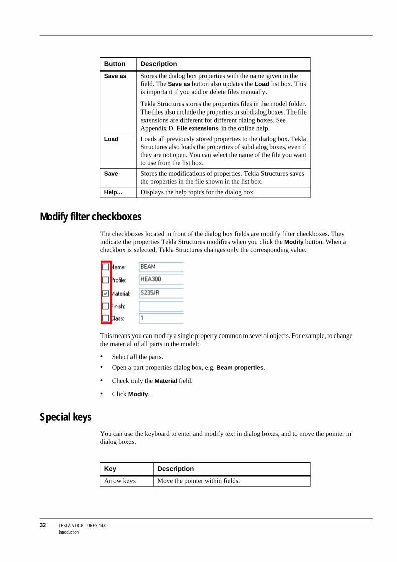
Modify filter checkboxesThe checkboxes located in front of the dialog box fields are modify filter checkboxes. They indicate the properties Tekla Structures modifies when you click the Modify button. When a checkbox is selected, Tekla Structures changes only the corresponding value.
This means you can modify a single property common to several objects. For example, to change the material of all parts in the model:
• Select all the parts.• Open a part properties dialog box, e.g. Beam properties.
• Check only the Material field.
• Click Modify.
Special keysYou can use the keyboard to enter and modify text in dialog boxes, and to move the pointer in dialog boxes.
Button Description
Save as Stores the dialog box properties with the name given in the field. The Save as button also updates the Load list box. This is important if you add or delete files manually.
Tekla Structures stores the properties files in the model folder. The files also include the properties in subdialog boxes. The file extensions are different for different dialog boxes. See Appendix D, File extensions, in the online help.
Load Loads all previously stored properties to the dialog box. Tekla Structures also loads the properties of subdialog boxes, even if they are not open. You can select the name of the file you want to use from the list box.
Save Stores the modifications of properties. Tekla Structures saves the properties in the file shown in the list box.
Help... Displays the help topics for the dialog box.
Key Description
Arrow keys Move the pointer within fields.

TEKLA STRUCTURES 14.0 33Introduction
See also Appendix E, Reserved shortcuts, in the online help.
1.5 Specifying pointsMost Tekla Structures commands ask you to pick points to position objects in a model. Snap priority, snap switches, and snap settings all affect picking.
Snap zone Each object has a snap zone. It defines how close you need to pick to hit a position. When you pick within the snap zone of an object, Tekla Structures automatically snaps to the closest pickable point on that object.
Snap priority If you pick and hit several positions simultaneously, Tekla Structures snaps to the position with the highest snap priority. To control which positions you can pick, use snap switches. They also define the snap priority of positions. See Snap switches (p. 33).
Snap switchesSnap switches specify exact locations on objects, for example, end points, midpoints, and intersections. Snap switches help you to pick points to position objects precisely without having to know the coordinates or create additional lines or points. You can use snap switches any time Tekla Structures prompts you to specify a point, for example, if you are creating a beam.
Main snap switches
The two main snap switches illustrated in the following table define whether you can pick reference points or any other points on objects, e.g. part corners. These switches have the highest priority. If both these switches are off, you cannot pick any positions, even if all the other switches are on.
Tab Moves the pointer to the next field or button in the dialog box. You can also scroll through lists using Tab.
Del, Backspace Delete characters.
Key Description
You can set the snap zone using the variable XS_PIXEL_TOLERANCE. Enter the snap zone dimension in pixels.

34 TEKLA STRUCTURES 14.0Introduction
Other snap switches
The following table lists the remaining snap switches. You can have Tekla Structures display the snap symbols in the model when you move the mouse pointer over objects. See Snap settings (p. 35).The snap symbol is green for objects inside components, and yellow for model objects.
IconPositions to pick Description Symbol
Reference points You can pick the object refer-ence points, i.e., the points that have handles. See Part loca-tion (p. 82).
Large
Geometric points You can pick any points on objects.
Small
IconPositions to pick Description Symbol
Points Snaps to points and grid line intersections.
End points Snaps to end points of lines, polyline segments, and arcs.
Centers Snaps to centers of circles and arcs.
Midpoints Snaps to midpoints of lines, polyline segments, and arcs.
Intersections Snaps to intersections of lines, polyline segments, arcs, and circles.
Perpendicular Snaps to points on objects that form a perpendicular align-ment with another object.
Nearest point Snaps to the nearest points on objects, e.g. any point on part edges or lines.
Free Snaps to any position.

TEKLA STRUCTURES 14.0 35Introduction
Overriding snap switches
To temporarily override current snap switch settings, do one of the following:
• Right-click and select the appropriate snap option from the pop-up menu.• Click an icon on the Snap override toolbar.
This will only override the snap settings for the next point you pick.
Numeric snap locations
You can also key in position coordinates to snap to using the Enter a numeric location toolbar. For more information, see Snapping (p. 177).
Snap settingsThe first list box on the Snapping toolbar defines the depth of each position you pick. The following options are available:
• 3D
Tekla Structures picks positions in 3D space.
• View plane
Tekla Structures projects picked positions onto the view plane.
• Auto
In perspective views, this option works like the 3D option. In non-perspective views, it works like the View plane option.
Snap switch settingsClick Tools > Options > Options... > Mouse settings. Use the Mouse settings dialog box to:
• Set Tekla Structures to display snap symbols and tooltips for the available snap points when you move the mouse pointer over objects.
• Define a snap grid and switch it on.
XsnapTo make it easier to snap to points and position, you can use Xsnap and have Tekla Structures display visual cues when you pick. Click Tools > Options > Xsnap, or use the shortcut T. The cursor turns into a magenta crosshair. As you move the cursor over objects, you can see it snap to positions.
If there is more than one point available to snap to, use the Tab key to cycle forward through the snap points, and Shift+Tab to cycle backwards through them. Click the left mouse button to select the appropriate point.

36 TEKLA STRUCTURES 14.0Introduction
Binding objects to planesWhen you create distances to bind model objects together, use the second list box on the Snapping toolbar to select the plane to bind the object to. The options are boundary, center, outline, and cut planes of parts, and grid planes. Grid planes are available only in the Model Editor.
For more information on other plane types, see Plane types in the online help.
1.6 Selecting model objectsTo use Tekla Structures effectively, you need to know how to select objects and use select switches. Selection filter settings also affect which objects you can select. See Selection filter (p. 153).
How to select objectsYou need to select objects to carry out many Tekla Structures commands. You can select objects as a sequence of single selections and/or area selections. Tekla Structures highlights the selected objects.
You can use the following techniques to modify the current selection:
Grid plane

TEKLA STRUCTURES 14.0 37Introduction
Technique Description
Single objects When you select objects using the mouse button, without pressing any other keys, every pick or drag selects objects. All previously selected objects are dese-lected.
Enclosing window selection
Drag the mouse from left to right to select all objects totally within that rectangular area.
Crossing window selection
Drag the mouse from right to left to select all objects totally or partly within that rectangular area.
Right-click To select an object and open its pop-up menu, click the object with the right mouse button.
This feature is active if you have a check mark next to Select on Right-Click in Tools > Options.
Nested compo-nents
To examine and work with nested components, hold down the Shift key and scroll with the mouse wheel.
See also Main select switches (p. 38).Nested assemblies To examine and work on different assembly levels,
hold down the Shift key and scroll with the mouse wheel. An orange box indicates the assembly which you can select.
See also Main select switches (p. 38).Assembly or cast unit
Press the Alt key while clicking a part to select the entire cast unit or assembly containing that part.

38 TEKLA STRUCTURES 14.0Introduction
Controlling the selectionMain select switches
The main select switches shown in the following table set whether you can select objects in component or assembly hierarchy. These switches have the highest priority.
Handles When you want to select only the handles of a part, select the part, press the Alt key and select the part again with enclosing window selection.
See also Handles (p. 82).Adding Press the Shift key and select objects, to add to the
current selection.Modifying To toggle the current selection on and off, press the
Ctrl key during selection. Tekla Structures deselects the objects, which are already selected and selects those, which are not previously selected.
Technique Description
IconSelectable objects Description
Components When you click any object belonging to a component, Tekla Structures selects the component symbol and highlights (does not select) all component objects.
Component objects Objects created automatically by a compo-nent can be selected.
Assemblies and cast units
When you click any object in an assembly or a cast unit, Tekla Structures selects the assembly or cast unit and highlights all objects in the same assembly or cast unit.
Objects in assem-blies and cast units
You can select single objects in assemblies and cast units.
You can use the Select components switch to select reference
models, and the Select objects in components switch to select reference model objects. For more information, see Selecting reference models and reference model objects.
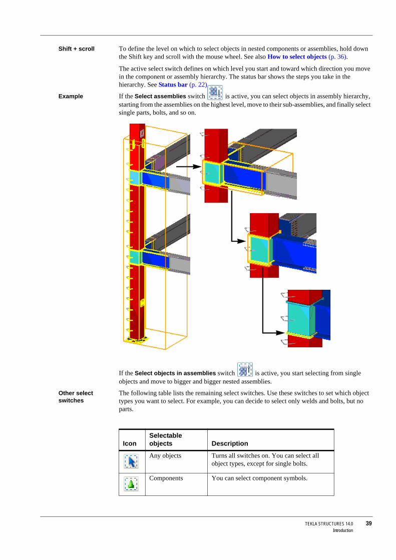
TEKLA STRUCTURES 14.0 39Introduction
Shift + scroll To define the level on which to select objects in nested components or assemblies, hold down the Shift key and scroll with the mouse wheel. See also How to select objects (p. 36).
The active select switch defines on which level you start and toward which direction you move in the component or assembly hierarchy. The status bar shows the steps you take in the hierarchy. See Status bar (p. 22).
Example If the Select assemblies switch is active, you can select objects in assembly hierarchy, starting from the assemblies on the highest level, move to their sub-assemblies, and finally select single parts, bolts, and so on.
If the Select objects in assemblies switch is active, you start selecting from single objects and move to bigger and bigger nested assemblies.
Other select switches
The following table lists the remaining select switches. Use these switches to set which object types you want to select. For example, you can decide to select only welds and bolts, but no parts.
IconSelectable objects Description
Any objects Turns all switches on. You can select all object types, except for single bolts.
Components You can select component symbols.
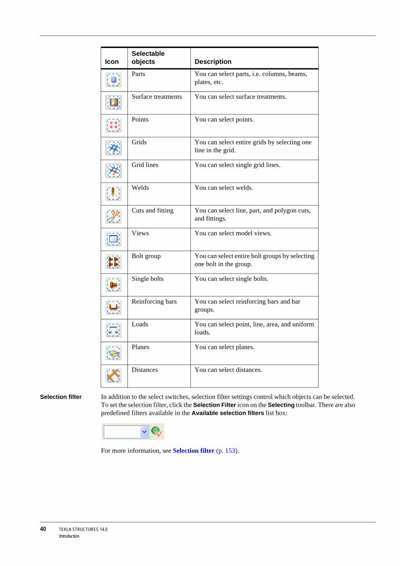
40 TEKLA STRUCTURES 14.0Introduction
Selection filter In addition to the select switches, selection filter settings control which objects can be selected. To set the selection filter, click the Selection Filter icon on the Selecting toolbar. There are also predefined filters available in the Available selection filters list box:
For more information, see Selection filter (p. 153).
Parts You can select parts, i.e. columns, beams, plates, etc.
Surface treatments You can select surface treatments.
Points You can select points.
Grids You can select entire grids by selecting one line in the grid.
Grid lines You can select single grid lines.
Welds You can select welds.
Cuts and fitting You can select line, part, and polygon cuts, and fittings.
Views You can select model views.
Bolt group You can select entire bolt groups by selecting one bolt in the group.
Single bolts You can select single bolts.
Reinforcing bars You can select reinforcing bars and bar groups.
Loads You can select point, line, area, and uniform loads.
Planes You can select planes.
Distances You can select distances.
IconSelectable objects Description
TEKLA STRUCTURES 14.0 41Introduction
Canceling object selectionYou can cancel the object selection process if the selection takes over a defined period of time. For example, if you are working on a large model and you accidentally select all or part of the model, you can cancel the selection if it takes over 5000 milliseconds to complete.
Usage 1. Click Tools > Options > Advanced Options > Modeling Properties.2. Set the cancellation value for the variable XS_OBJECT_SELECTION_CONFIRMATION.
The default value is 5000 milliseconds.
1.7 Using commandsAs you become familiar with Tekla Structures, you will find that there are several ways to do some operations. This section introduces most of the ways. Later in this manual, we refer to this section or present only the way(s) most useful for a first-time user. After some practice, you may choose a different way.
Executing commandsThere are several ways to execute commands in Tekla Structures.
Icon You can use icons:
• Single-click an icon just to execute the command.• Double-click an icon to display the properties of the object type, and to execute the
command.
Pull-down menu You can execute commands using pull-down menus. Tekla Structures contains two types of menus for basic objects:
• The commands on the Properties menu set the properties of different object types.• The commands on the Points, Parts, and Create menus, for example, create objects using
the properties of each object type.
Pop-up menu A pop-up menu appears when you click the right mouse button. If you have an object selected, the commands on the pop-up menu relate to that object.
Repeating commandsTo repeat the last command, do one of the following:
• Click Edit > Repeat Last Command.• Press Enter.
Creating objectsMost of the commands you run in Tekla Structures create objects. To create an object, or multiple objects:
• Open the object type’s properties dialog box and set the object properties.• Place the object(s) in the model.
You can carry out these steps in any order.
For example To create objects:

42 TEKLA STRUCTURES 14.0Introduction
1. Double-click the icon of the object type you want to create. Tekla Structures displays the properties dialog box.
2. Enter or modify the object properties.
3. Click Apply or OK. See also Common buttons (p. 31).
4. Pick points to place the object(s).
To position objects without defining their properties:
1. Single-click an icon, or a menu command.2. Pick points to place the object(s). Tekla Structures creates the object using the current
properties of the object type. See also Modifying objects (p. 42).
Modifying objectsTo modify the properties of an object, or multiple objects:
• Select the object(s) to modify.• Open the properties dialog box and modify the object properties.
You can carry out these steps in any order.
For example To modify objects:
1. Double-click one of the objects you want to modify to open the object properties dialog box.2. Modify the properties. See also Modify filter checkboxes (p. 32).
3. Select the remaining object(s) to modify. See also How to select objects (p. 36).
4. Click Modify.
See also For information on how to resize and move objects, see Handles (p. 82) and Copying and moving objects (p. 138).
Using commands simultaneouslyTransparency You can use some Tekla Structures commands transparently. This means that you can execute
these commands while another command is still running. For example, the commands on the Zoom and Points toolbars are transparent.
Ending commandsTo cancel or end commands, do one of the following:
• On the Edit menu, click Interrupt.• Right-click and select Interrupt from the pop-up menu.
• Press the Esc key.
To create several objects with the same properties, pick multiple points. The object commands in Tekla Structures run until you end them or use another command. See also Ending commands (p. 42).

TEKLA STRUCTURES 14.0 43Getting Started
2 Getting Started
Introduction When you start a new Tekla Structures model, the first objects you create are grids, views, and points.
This chapter explains the basic skills you need to create a new model, grids, views, and points in Tekla Structures. We will begin with the basic concepts, followed by general descriptions of the grid, view, and point properties. Finally we will show you how to create and manage these modeling aids in practice.
Assumed ba-ckground
If you are new to Tekla Structures, we recommend that you first read Chapter 1, Introduction (p. 15), to gain a basic understanding of Tekla Structures.
Contents This chapter is divided into the following sections:
• Basics (p. 43)• Grids (p. 50)
• Views (p. 55)
• Points (p. 61)
• Construction planes, lines, and circles (p. 62)
How to use this chapter
You can start by creating either Views (p. 55) or Grids (p. 50).
2.1 BasicsIn this section This section presents basic Tekla Structures vocabulary and concepts so that you can start
modeling. The illustration below shows the modeling guides you use in Tekla Structures windows.

44 TEKLA STRUCTURES 14.0Getting Started
View To see your Tekla Structures model from virtually any angle, you can move and rotate the model. See Examining the model (p. 125). You can also create views. A view is a representation of a model from a specific location. Each view is displayed in its own window inside the Tekla Structures window.
Coordinate system
The symbol with three axes (x, y, and z) represents the local coordinate system and indicates the direction of the model. It is located in the lower right corner of the model view. The coordinate symbol follows the work plane.
The green cube in a wire frame view (see View type (p. 57)) represents the global coordinate system and lies at the global point of origin.
Points are red outside the view plane
Grid is on the view plane
Green dashed lines outline the work area
Points are yellow on the view plane
Arrow symbol indicates the work plane
The coordinates symbol indicates the direction of the model

TEKLA STRUCTURES 14.0 45Getting Started
Work plane The red coordinate arrow symbol indicates the work plane, which is the current local coordinate system of the model. The arrow symbol shows the xy plane. The z direction follows the right-hand rule. You can reset the work plane so as to ease modeling and placing objects. Most of the commands, which are dependent on the coordinate system, use work plane coordinates; e.g. creating points, part positioning, and copying always comply with the work plane coordinate system. The work plane is the same in all views.
Work area Tekla Structures indicates the work area of a view using green, dashed lines. Defining the work area makes it faster and easier to work with the model. Objects outside the work area still exist, but they are not visible. So you can confine to a substructure, for example, and the views to the model are simpler and quickly updated.
Grid and view plane
Dash-and-dot lines show the projections of the grids which are visible on the view plane.
The appearance of points also shows which view plane you are using. Points located in the view plane are yellow. Points outside the view plane are red.
Opening a modelTo open a Tekla Structures model:
1. Click File > Open... or .You can only have one model open at a time. If you already have a model open, Tekla Structures prompts you to save that model.
2. In the Open dialog box, select the model.
By default, Tekla Structures searches for models in the folder you specified when you installed Tekla Structures. If your model is in another folder, click Browse... to browse for the model folder, or use the Look in list box with the recently used folders.
3. Click OK to open the model.

46 TEKLA STRUCTURES 14.0Getting Started
If no views are visible after you have opened a model, Tekla Structures prompts you to select one. For more information, see Opening, closing, and deleting named views (p. 60).
The Open dialog box provides you with the following information:
• Whether the model was last saved in single-user or multi-user mode (Model type)• The version of Tekla Structures the model was created or last saved in
• Designer
• Description
• Template that was used as a basis when creating this model
• Environment
The Designer and Description columns show information from the Project properties dialog box. See Project setup (p. 47).
Switching between single-user and multi-user modesYou can easily switch between single-user and multi-user modes by using the different options in the Open dialog box.
To open a multi-user model in single-user mode:
1. In the Open dialog box, select the multi-user model.2. Right-click and select Open as single-user model from the pop-up menu.
To open a single-user model in multi-user mode:
1. In the Open dialog box, select the single-user model.2. Right-click and select Open as multi-user model from the pop-up menu.
3. Tekla Structures asks for the name of the server. In the Open as multi-user model dialog box, enter the server name or select it from the list box, and then click OK.
Changing the server
To change the Tekla Structures server of a multi-user model:
1. In the Open dialog box, select the multi-user model.2. Right-click and select Change server from the pop-up menu.
3. Tekla Structures asks for the name of the new server. In the Change server dialog box, enter the server name or select it from the list box, and then click OK.
You can also double-click a model on the list to open it, or use the Model name list box to open a recently used model.
You can sort models by clicking the column titles.
When the models are sorted alphabetically by their names, you can use the keyboard to select models. For example, when you type N, Tekla Structures selects the first model starting with an N.
If you change the server of a model, but the connection to the new server cannot be established, the old connection is restored.
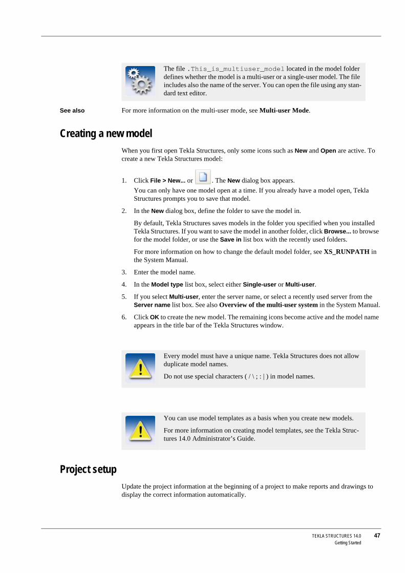
TEKLA STRUCTURES 14.0 47Getting Started
See also For more information on the multi-user mode, see Multi-user Mode.
Creating a new modelWhen you first open Tekla Structures, only some icons such as New and Open are active. To create a new Tekla Structures model:
1. Click File > New... or . The New dialog box appears.You can only have one model open at a time. If you already have a model open, Tekla Structures prompts you to save that model.
2. In the New dialog box, define the folder to save the model in.
By default, Tekla Structures saves models in the folder you specified when you installed Tekla Structures. If you want to save the model in another folder, click Browse... to browse for the model folder, or use the Save in list box with the recently used folders.
For more information on how to change the default model folder, see XS_RUNPATH in the System Manual.
3. Enter the model name.
4. In the Model type list box, select either Single-user or Multi-user.
5. If you select Multi-user, enter the server name, or select a recently used server from the Server name list box. See also Overview of the multi-user system in the System Manual.
6. Click OK to create the new model. The remaining icons become active and the model name appears in the title bar of the Tekla Structures window.
Project setupUpdate the project information at the beginning of a project to make reports and drawings to display the correct information automatically.
The file .This_is_multiuser_model located in the model folder defines whether the model is a multi-user or a single-user model. The file includes also the name of the server. You can open the file using any stan-dard text editor.
Every model must have a unique name. Tekla Structures does not allow duplicate model names.
Do not use special characters ( / \ ; : | ) in model names.
You can use model templates as a basis when you create new models.
For more information on creating model templates, see the Tekla Struc-tures 14.0 Administrator’s Guide.
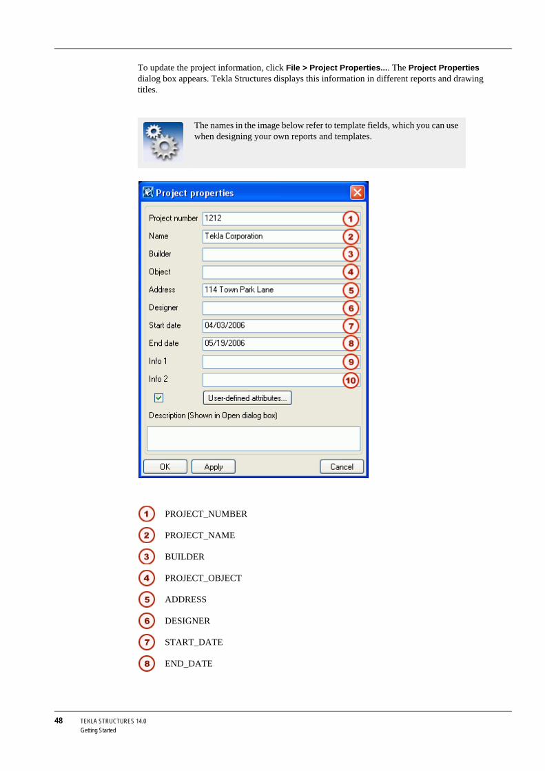
48 TEKLA STRUCTURES 14.0Getting Started
To update the project information, click File > Project Properties.... The Project Properties dialog box appears. Tekla Structures displays this information in different reports and drawing titles.
The names in the image below refer to template fields, which you can use when designing your own reports and templates.
PROJECT_NUMBER
PROJECT_NAME
BUILDER
PROJECT_OBJECT
ADDRESS
DESIGNER
START_DATE
END_DATE

TEKLA STRUCTURES 14.0 49Getting Started
Before starting a new project, read also Using effectively in the online help.
Defining the work area and shifting the work planeWork area You can define the work area to suit particular situations, for example, to concentrate on a
particular area of the model. You can shrink and expand the work area by picking the corner points of the new work area, or size the work area to include selected parts, or all model objects. You can define the work area in a selected view, or in all visible views.
To define the work area, use a command from the View menu:
Work plane The current work plane defines the local coordinate system of a Tekla Structures model. You can set the work plane to any position by picking points, parallel to one of the global basic planes, or on a part or view plane. The current work plane is model-specific, so it relates to all views.
When modeling sloped parts, shifting the work plane helps you to place parts accurately.
To shift the work plane, use the icons on the View toolbar, or select a command from the View menu. The following table lists the commands for setting the work plane, and gives a short description of each one:
INFO1
INFO2
Command Icon Description
Fit Work Area Using Two Points
Sets the work area based on two corner points you pick on the view plane. The depth of the work area is the same as the view depth.
To Entire Model in All Views
Fits the work area to include all model objects in all visible views.
To Entire Model in Selected Views
Fits the work area to include all model objects in the selected views.
To Selected Parts in All Views
Fits the work area to include the selected model objects in all views.
To Selected Parts in Selected Views
Fits the work area to include the selected model objects in the selected views.
Command Icon Description
Parallel To XY(Z) Plane...
Sets the work plane parallel to xy, xz, or yz plane.
Using One Point Sets the work plane according to one picked point.
Using Two Points Sets the work plane according to two picked points.

50 TEKLA STRUCTURES 14.0Getting Started
Saving a model and exiting Tekla Structures
To save a model, click File > Save or .
Save as Click File > Save as... to save a model with a new name, or to give a new model a specific name.
Autosave Tekla Structures automatically saves the model at set intervals. To set the interval and define the location of autosave files, see Autosave in the online help.
Exit To exit Tekla Structures, close the Tekla Structures window, or click File > Exit. A confirmation dialog box appears and you can choose whether or not to save the model.
2.2 GridsIntroduction So that you can easily locate objects in your model, we strongly advise that you create a modular
grid. The Tekla Structures grid is shown on the view plane by dash-and-dot lines. See also View plane (p. 56).
You can have more than one grid in a model. You may want to create a large-scale grid for the entire structure, and smaller grids for some detailed sections. Grids are rectangular. You can also create single grid lines and attach them to an existing grid.
Using Three Points Sets the work plane according to three picked points.
Parallel To View Plane Sets the work plane to be equivalent to the view plane of a picked view.
To Part Front Plane Sets the work plane parallel to the front plane of a part.
To Part Top Plane Sets the work plane parallel to the top plane of a part.
To Part Back Plane Sets the work plane parallel to the back plane of a part.
To Part Bottom Plane Sets the work plane parallel to the bottom plane of a part.
Command Icon Description
Saving models differs in multi-user mode. See Multi-user mode in the online help.

TEKLA STRUCTURES 14.0 51Getting Started
You can pick grid lines and grid line intersections. See also Specifying points (p. 33).
Grid propertiesTo access the Grid dialog box, do one of the following:
• Click Modeling > Create Grid....
• Use the Select grid switch and double-click an existing grid.
Grid coordinates The x and y coordinates of a grid are relative. This means that the entries for x and y are always relative to the previous entry. The z coordinates are absolute meaning that entries for z are absolute distances from the work plane origin.
There are two ways to enter the x or y coordinates of grid lines:
• individually, e.g. 0 4000 4000, or• several grid lines with equal spacing, e.g. 0 2*4000.
Both create three lines with the spacing of 4000.
Labels Labels are the names of the grid lines shown in views. The names in the X field are associated with the grid lines parallel to the y axis and vice versa. The Z field is for the names of levels parallel to the work plane. If you wish, you can leave the label fields empty.
Line extensions You can also define the Line extensions over the given grid coordinates and the Origin of the grid.
To position objects in a radial or circular pattern:
• Create one grid line and use the Edit > Copy Special > Rotate command to copy it.
• Use construction lines and circles. See Construction planes, lines, and circles (p. 62).
Use a zero at the start to represent a grid on the 0,0 coordinate and spaces as separators for coordinates. You can have a maximum of 1024 grid characters in the co-ordinates field.
When working with very large grids, having the grid labels always visible might slow down Tekla Structures. To hide the grid labels when you zoom in, use the variable XS_ADJUST_GRID_LABELS.

52 TEKLA STRUCTURES 14.0Getting Started
Magnetism You can make grids and grid lines act magnetically so that the objects on the grid lines follow if you move the grid line.
To bind objects to grid lines, select the Magnetic grid plane checkbox.
In the Extension for magnetic area field, enter a distance from the grid line to extend the area within which the objects are bound to the grid lines.
Grid line propertiesYou can also create and modify single grid lines. To access the Grid Line Properties dialog box:
• Use the Select grid lines switch and double-click an existing grid line.
Working with gridsAutomatic grid When you create a new model, Tekla Structures automatically creates a grid and a view
according to the saved standard properties.
See also Creating grids (p. 53)
Creating grid lines (p. 53)
Using select switches on grids (p. 53)
Modifying grids (p. 53)
Modifying grid lines (p. 54)
Line extensions
Work plane origin
Grid labels
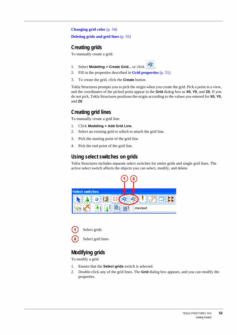
TEKLA STRUCTURES 14.0 53Getting Started
Changing grid color (p. 54)
Deleting grids and grid lines (p. 55)
Creating gridsTo manually create a grid:
1. Select Modeling > Create Grid... or click .2. Fill in the properties described in Grid properties (p. 51).
3. To create the grid, click the Create button.
Tekla Structures prompts you to pick the origin when you create the grid. Pick a point in a view, and the coordinates of the picked point appear in the Grid dialog box as X0, Y0, and Z0. If you do not pick, Tekla Structures positions the origin according to the values you entered for X0, Y0, and Z0.
Creating grid linesTo manually create a grid line:
1. Click Modeling > Add Grid Line.2. Select an existing grid to which to attach the grid line.
3. Pick the starting point of the grid line.
4. Pick the end point of the grid line.
Using select switches on gridsTekla Structures includes separate select switches for entire grids and single grid lines. The active select switch affects the objects you can select, modify, and delete.
Modifying gridsTo modify a grid:
1. Ensure that the Select grids switch is selected.2. Double-click any of the grid lines. The Grid dialog box appears, and you can modify the
properties.
Select grids
Select grid lines

54 TEKLA STRUCTURES 14.0Getting Started
3. Click the Modify button to save the changes.
See also XS_ADJUST_GRID_LABELS
Modifying grid linesTo modify a grid line:
1. Ensure that the Select grid lines switch is selected.2. Double-click the grid line. The Grid Line Properties dialog box appears, and you can
modify the properties.
3. Click the Modify button to save the changes.
Moving grid lines using handles
Single grid lines have handles. When you select a grid line, the handles appear magenta. You can use handles to move the grid lines.
See also XS_ADJUST_GRID_LABELS
Working with grids (p. 52)
Changing grid colorUse the variable XS_GRID_COLOR to change the color of the grid in rendered views.
1. Click Tools > Options > Advanced Options > Model View.2. Set the RGB value for the variable XS_GRID_COLOR.
3. Close and reopen the view for the change to take effect.
If you modify a grid and have the checkboxes against the coordinate fields selected in the Grid dialog box, Tekla Structures deletes all single grid lines attached to the grid.
If you want to move the grid lines using the handles to make a skewed grid, you can do this on the local XY plane of the grid only.
Define the color using RGB values on a scale of 0 to 1. For example, to change the color to red, set the value to 1.0 0.0 0.0.
To find RGB values for colors:
1. Log on to Tekla Extranet.2. Select Tekla Structures - Hints & Tips - General and go to the How
to find perfect background color for your needs page.
3. Download the application.

TEKLA STRUCTURES 14.0 55Getting Started
Deleting grids and grid linesTo delete a grid:
1. Ensure that the Select grids switch is selected.2. Click any grid line, then right-click and select Delete from the pop-up menu.
To delete a grid line:
1. Ensure that the he Select grid lines switch is selected.2. Click the grid line you want to delete.
3. Right-click and select Delete from the pop-up menu.
See also Grids (p. 50)
2.3 ViewsIntroduction There are several ways to create views in Tekla Structures. For example, you can create views:
• of the entire structure• of selected part(s) and component(s)
• along the grid lines
Each view has properties which define its appearance. You can change the appearance of a view after you create it so choose the creation method that suits you. This section describes the view-specific properties. You can open the view properties dialog box for each view, to view or modify the properties.
You can have up to nine views on the screen at the same time. If you try to open more than nine views, Tekla Structures displays a warning. If the view does not appear, check how many views you have open.
When you delete a grid, ensure that you do not have any other object(s) selected. If you have also other objects selected, Tekla Structures only deletes the objects, not the grid.
Unnamed views disappear when you close them. See Naming views (p. 56).
To switch between views, press Ctrl+Tab.

56 TEKLA STRUCTURES 14.0Getting Started
View planeEach view has a view plane on which the grids are visible and points are represented as yellow crosses.
Basic view plane Basic views are those parallel to the global basic planes, i.e. xy, xz, and zy. In basic views two axes always define the view plane and they appear in the plane name. The third axis is perpendicular to the view plane. It does not appear in the plane name. In the basic plane view, the model is shown from the direction of that third axis.
The view plane options for basic views are:
View plane co-ordinate
For basic views, you also define at which distance from the global origin the view plane is in direction of the third axis. The view plane coordinate equals this distance.
Other views For view types other than basic views, you define the view plane and coordinate by picking points, e.g. With three points, or they are defined automatically according to the chosen creation method/command, e.g. To work plane.
Moving the view plane
You can change the view plane by moving it like any other object. Click anywhere on the plain background, right-click and select Move Special > Linear... from the pop-up menu. See Copying and moving objects (p. 138) and Move (p. 140).
View propertiesNaming views Tekla Structures numbers views in order of creation, so you do not have to give each view a
specific name.
You should give a view a unique name if you need to open it in later sessions. See Opening, closing, and deleting named views (p. 60). When you exit the model, Tekla Structures only saves named views. Tekla Structures does not save unnamed views when you close them.
Moving a view plane may result in a situation such that view depth and work area do not intersect and thus nothing can be seen in the window.
In multi-user mode, it is very important to give views unique names. If several users have different views with the same name, the view settings of one user may randomly override the settings of another user.

TEKLA STRUCTURES 14.0 57Getting Started
View typeThe view type defines the appearance of the view. It also affects what methods you can use to rotate the model. The view type options are:
• Wire frame
Objects are transparent and their outlines are displayed. As the wire frame views use line graphics technique, redrawing views is quick.
• Rendered
Objects look more realistic because they are non-transparent and their surfaces are displayed as shown in the illustrations below. However, you can also choose the Wireframe or Shaded Wireframe option in the rendered views. Rotating the model in the rendered views is very convenient with the mouse.
RepresentationIn rendered views, you can define how Tekla Structures displays parts and component objects separately. The following options are available:
• Wireframe
Part outlines are displayed, surfaces are not, i.e. parts are transparent.
(In this example, component objects are displayed as Rendered.)
• Shaded Wireframe
Part outlines are displayed. Parts are transparent, and their surfaces are shaded.
(In this example, component objects are displayed as Rendered.)
• Hidden Lines
Parts are not transparent, i.e. underlying parts are not visible. Part surfaces are not displayed.

58 TEKLA STRUCTURES 14.0Getting Started
For more information on how objects are shown in views, see Displaying and hiding objects (p. 143).
ProjectionIf you choose the rendered view type, the projection can be:
• Orthogonal
All objects are of equal size (no perspective). When you zoom, text and point size remains the same. In addition, the zoom remains on part surfaces.
• Perspective
Distant objects appear smaller than close ones, as do text and points. You can zoom, rotate the model, or fly through it.
View angle Views can be:
• Plane
• 3D
Rotation Rotation is view-specific. You can rotate the model in 3D views using the mouse and keyboard (see Rotating the model (p. 129)), or by defining the rotation angle in the View properties dialog box. You can specify rotation angles around the z axis and around the x axis.
• Rendered
Part surfaces are displayed, i.e. parts are not transparent.
• Rendered (Dark Colors)
Parts are not transparent. Part outlines are displayed with brighter color, and part surfaces with darker color than in the Rendered option.
In rendered views, use the shortcuts Ctrl+1...5 and Shift+1...5 to set the desired representation for parts in the model and components.
Use the shortcut Ctrl+P or click View > Switch to 3D / Plane to switch between 3D and plane view.

TEKLA STRUCTURES 14.0 59Getting Started
View depth Every view has depth, which is the thickness of the displayed slice of model. You can define the depth separately upwards and downwards from the view plane. The objects within the displayed depth and the work area are visible in the model. However, objects created after the view are visible also outside the view depth. See Displaying and hiding objects (p. 143).
Defining grid view propertiesGrid views are views along the grid lines. Before creating grid views, you can define how many views Tekla Structures will create, how it will name the views, and which view properties it will use.
Number of views There are four options for the number of views:
• None
Tekla Structures does not create any views.
• One (First)
Tekla Structures only creates the view closest to the grid origin.
• One (Last)
Tekla Structures only creates the view furthest from the grid origin.
• All
Tekla Structures creates all views in grid planes in the relevant direction.
View name prefix View names consist of a prefix and a grid label, e.g. PLAN +3000. If the View name prefix field is left empty, no prefix is used. Tekla Structures adds a dash and a running number to the view name if view names are otherwise identical.
View properties Each view plane has its own view properties. See View properties (p. 56). You can load the properties from the current view properties with the option <applied values> or from saved view properties. The Show… button displays the view properties.
Creating and modifying viewsWhen you create a new model, you can select the Create default view and grid checkbox to have Tekla Structures automatically create a grid and a view according to the saved standard properties.
Creating To create views, use the commands on the View menu. The following table lists the commands for creating views and gives a short description of each one:
Command Icon Description
Create View of Model > 3D View...
Displays the Create 3D View dialog box and creates a 3D view.
Create View of Model > Using Two Points
Creates a view using two picked points.
Create View of Model > Using Three Points
Creates a view using three picked points.
Create View of Model > On Work Plane
Creates a view of the current work plane.

60 TEKLA STRUCTURES 14.0Getting Started
Modifying To modify a view, double-click anywhere on the plain background. The View Properties dialog box appears and you can modify the properties.
Opening, closing, and deleting named viewsTo view and open the existing named views, do one of the following:
• Click .• Click View > View List... to display the Views dialog box.
Tekla Structures lists all invisible named views on the left, and all visible views on the right.
To display or hide views, select the view(s) and use the arrows between the lists. You can also double-click a view in the Views dialog box to open or close it.
To select multiple views on lists, use the Shift and Ctrl keys when you select views. To deselect views, hold down the Ctrl key.
To delete a named view, select the view and click Delete.
See also Naming views (p. 56).
Refreshing the screen displayActive window To update and display the contents of an active window, do one of the following:
• Press Ctrl+U.• Right-click, then select Update Window.
• Click View > Zoom > Active Window > Update.
All windows To update the contents of all windows, click View > Update All. You can also use View > Redraw All to recalculate and redraw the contents of all the windows.
Click Window > Close All to close all the windows on the screen at the same time.
Create View of Model > Along Grid Lines...
Displays the Creation of Views Along Grid Lines dialog box and creates views along the grid lines of a selected grid.
Create View of Model > On Part Plane
Creates a view on the front, top, back or bottom plane of the selected part.
Create View of Part > 3D View
Creates a 3D view of the selected part.
Create View of Part > Default Views
Creates four basic views of the part.
Create View of Part > Undeformed View
Creates a view that shows a deformed part in undeformed form.
Create View of Compo-nent > 3D View
Creates a 3D view of the component.
Create View of Compo-nent > Default Views
Creates four basic views of the component.
Command Icon Description
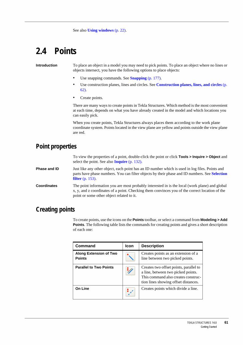
TEKLA STRUCTURES 14.0 61Getting Started
See also Using windows (p. 22).
2.4 PointsIntroduction To place an object in a model you may need to pick points. To place an object where no lines or
objects intersect, you have the following options to place objects:
• Use snapping commands. See Snapping (p. 177).• Use construction planes, lines and circles. See Construction planes, lines, and circles (p.
62).
• Create points.
There are many ways to create points in Tekla Structures. Which method is the most convenient at each time, depends on what you have already created in the model and which locations you can easily pick.
When you create points, Tekla Structures always places them according to the work plane coordinate system. Points located in the view plane are yellow and points outside the view plane are red.
Point propertiesTo view the properties of a point, double-click the point or click Tools > Inquire > Object and select the point. See also Inquire (p. 132).
Phase and ID Just like any other object, each point has an ID number which is used in log files. Points and parts have phase numbers. You can filter objects by their phase and ID numbers. See Selection filter (p. 153).
Coordinates The point information you are most probably interested in is the local (work plane) and global x, y, and z coordinates of a point. Checking them convinces you of the correct location of the point or some other object related to it.
Creating pointsTo create points, use the icons on the Points toolbar, or select a command from Modeling > Add Points. The following table lists the commands for creating points and gives a short description of each one:
Command Icon Description
Along Extension of Two Points
Creates points as an extension of a line between two picked points.
Parallel to Two Points Creates two offset points, parallel to a line, between two picked points. This command also creates construc-tion lines showing offset distances.
On Line Creates points which divide a line.

62 TEKLA STRUCTURES 14.0Getting Started
2.5 Construction planes, lines, and circlesConstruction planes, lines, and circles help you place other objects. For example, you can easily pick the points at intersections of construction lines and circles. The snap priority of construction objects is the same as with the other lines.
Construction objects remain in the model when you update or redraw views and windows. They do not appear in drawings.
To create construction objects, use the icons on the Points toolbar or select a command on the Modeling menu. The following table lists the commands for creating construction objects and gives a short description of each one:
On Plane... Displays the Point Array dialog box and creates a point array relative to the current work plane.
Projected Points on Line Projects a picked point onto a picked line.
Using Center and Arc Points
Creates points along an arc.
Using Three Arc Points Creates points as an extension of an arc defined by three picked points.
Tangent to Circle Creates a point where a circle and a line meet tangentially.
At Intersection > Of Two Lines
Creates a point at the intersection of two lines.
At Intersection > Of Plane and Line
Creates a point where a line inter-sects with a plane.
At Intersection > Of Part and Line
Creates points where a line intersects with a part surface.
At Intersection > Of Circle and Line
Creates points where a circle and a line intersect.
At Intersection > Of Two Part Axes
Creates a point where the axes of two parts intersect, and projects the point onto the view plane.
At Any Position Creates a point to any position you pick.
Bolt Points Creates points at the bolt center points of the picked bolt groups.
Grid Points Creates points at the intersections of grid lines on the view plane.
Command Icon Description

TEKLA STRUCTURES 14.0 63Getting Started
Command Icon Description
Construction plane Creates a plane.
Add Construction Line Creates a construction line between any two picked 3D points.
Add Construction Circle Using Center Point and Radius
Creates a construction circle in the view plane of the first view picked.
Add Construction Circle Using Three Points
Creates a construction circle defined by three picked 3D points.

64 TEKLA STRUCTURES 14.0Getting Started

TEKLA STRUCTURES 14.0 65Parts
3 Parts
Introduction In Tekla Structures, we use the term parts to refer to the basic components of a model. These are the building blocks of the physical model. For structural analysis purposes, we use the term members to mean load-bearing parts.
The main concrete parts are:
• beam• polybeam
• column
• pad footing
• strip footing
• panel
• slab
The main steel parts are:
• beam• curved beam
• orthogonal beam
• polybeam
• column
• twin profile
• contour plate
In this chapter This chapter explains how to create and modify parts using different materials and profiles. It also includes a general description of part properties and an overview of part commands. You can find step-by-step instructions for all these commands in the online help.
Assumed ba-ckground
We assume that you have read Chapter 1, Introduction (p. 15), or have comparable knowledge of Tekla Structures. Before you start to create parts, you need to create grids, views, and points, as explained in Chapter 2, Getting Started (p. 43).
Contents This chapter is divided into the following sections:

66 TEKLA STRUCTURES 14.0Parts
• Part properties (p. 66)• Cast units and assemblies (p. 72)
• Numbering parts (p. 79)
• Part location (p. 82)
• Surface treatment (p. 89)
• Steel part commands (p. 102)
• Concrete part commands (p. 103)
3.1 Part propertiesIntroduction Every part has properties which define it (e.g. material, profile, location, etc.). This section
describes the basic part-specific properties. Use the part properties dialog box to view or modify the properties of a part.
Filtering by prop-erties
You can use part properties in filters. For example, you can select, modify, or hide parts based on their properties. See Filter (p. 152).
In reports and drawings
You can include part properties and user-defined attributes in drawing and report templates.
Name The name of the part is user-definable. Tekla Structures uses part names in reports and drawing lists, and to identify parts of the same type, e.g. beams or columns.

TEKLA STRUCTURES 14.0 67Parts
Finish Finish is user-definable. It describes how the part surface has been treated, e.g. with anti-corrosive paint, hot galvanized, fire retardant coating, etc.
Class Use Class to group parts. To display parts of different classes in different colors, click View > Representation > Object Representation... and select Color by class in the Color list box. See also Colors (p. 166).
ProfileTekla Structures contains standard, parametric, and user-defined profiles.
Standard profiles When you first start Tekla Structures, the profile catalog contains standard, environment-specific profiles. The properties of these library profiles conform to industry standards, so you should not edit them. You can add profiles to the profile catalog. See The profile catalog in the online help.
Parametric profiles
Parametric profiles are partly user-definable, they have a predefined shape, but you determine their size by giving one or more parameters. You can use parametric profiles to closely “model” profiles that are standard in specific environments, but do not exist in the Tekla Structures profile catalog. Parametric profile names have specific prefixes and include dimension values. These are described in Appendix A, Parametric Profiles (p. 221). If you want to define alternative prefixes for parametric profiles, see Customizing parametric profiles in the online help. Dimension values in parametric profile names are separated by standard separators -, X, /, or *. If you want to define additional separators, see XS_PARAMETRIC_PROFILE_SEPARATOR and XS_USER_DEFINED_PARAMETRIC_PROFILE_SEPARATORS in the online help.
User-defined profiles
You can also create your own profiles and save them in the profile catalog. For example, you could create a user-defined profile pitched, with different cross sections at the beginning and end of the profile. You can also define cross sections. To create user-defined cross sections, you pick the points which define the cross section corners. To create your own profiles, see Sketching and using cross sections (p. 195) and Adding a standard (fixed) user-defined profile in the online help.
Selecting a profileTo select the profile of a part, click Select... next to the Profile field in the part properties dialog box. The Select Profile dialog box appears.

68 TEKLA STRUCTURES 14.0Parts
You can select a profile from the tree which lists profiles contained in the profile catalog. Profiles are grouped in the tree according to rules (such as profile type) which you can define and modify. Only the profile types that are relevant to the material of the part are shown. For more information on how to modify the profile catalog and rules, and how to associate profile types with materials, see The profile catalog and Working with rules in the online help.
If you select a parametric profile, enter the profile dimensions in the Value column.
All profiles and details
If you select the Show all profiles checkbox, Tekla Structures includes all the profiles in the profile catalog in the tree. To see all the properties of profiles, select the Show details checkbox.
For user-defined profiles Tekla Structures also displays cross section information.
When you have selected a profile, click Apply or OK.
Standard profile
Parametric profile

TEKLA STRUCTURES 14.0 69Parts
Using standardized values for profile dimensionsYou can define standardized values for the dimensions of parametric profiles in the industry_standard_profiles.inp file in the ..\environments\*your_environment*\system folder.
To use these values, in the Select profile dialog box, select a parametric profile for which you have defined standardized values and select the Use industry standardized values only checkbox. You can select the profile dimensions from a list box in the Value column.
You can edit the industry_standard_profiles.inp file using any standard text editor (for example, Notepad). Use the following format:
• Profile and profile subtype• Parameters separated by spaces
• Units for each parameter
• Standardized values for each parameter (own row for each dimension combination)
Example In the following example we define standardized combinations of dimension values for a C profile:
MaterialThe material catalog contains standard, environment-specific materials. You can add, modify, and delete materials and grades.
Defining the material of a partSelect... To select the material of a part, click Select... next to the Material field in the part properties
dialog box. The Select material dialog box appears. You can select the material and grade from the tree, which displays all the materials in the material catalog.
You can also:
• Use the Profile name list box in the Select profile dialog box to select a recently used profile.
• Enter a profile name in the Profile field in the part properties dialog box. Parametric profile names must be in the format shown in Appendix A, Parametric Profiles (p. 221).
industry_standard_profiles.inpC h*b*th b tmm mm mm75 35 575 35 675 35 7100 40 7100 40 8100 40 9
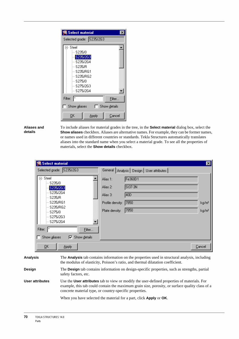
70 TEKLA STRUCTURES 14.0Parts
Aliases and details
To include aliases for material grades in the tree, in the Select material dialog box, select the Show aliases checkbox. Aliases are alternative names. For example, they can be former names, or names used in different countries or standards. Tekla Structures automatically translates aliases into the standard name when you select a material grade. To see all the properties of materials, select the Show details checkbox.
Analysis The Analysis tab contains information on the properties used in structural analysis, including the modulus of elasticity, Poisson’s ratio, and thermal dilatation coefficient.
Design The Design tab contains information on design-specific properties, such as strengths, partial safety factors, etc.
User attributes Use the User attributes tab to view or modify the user-defined properties of materials. For example, this tab could contain the maximum grain size, porosity, or surface quality class of a concrete material type, or country-specific properties.
When you have selected the material for a part, click Apply or OK.

TEKLA STRUCTURES 14.0 71Parts
To modify the material catalog, see The material catalog in the online help.
User-defined attributesUser-defined attributes provide extra information about a part. Attributes can consist of numbers, text, or lists. The following table explains what you can use attributes for:
For more information on defining attributes using the objects.inp file, see Adding properties in the online help.
You can also enter a material name in the Material field in the part prop-erties dialog box.
Attribute Can be used...
Comment In part and weld marks in Tekla Structures drawings, or in projects.
Shorten When drawings of the parts are created, Tekla Struc-tures decreases the true length of the part by this value. This is useful when creating assembly drawings of bracing bars which should always be under tension.
Camber In part marks in Tekla Structures drawings.Prelim mark To obtain preliminary marks for parts in reports. To
assign part position numbers to preliminary marks, click Drawings & Reports > Numbering > Save Preliminary Numbers when you number parts. To check the preliminary mark of a selected object, click Tools > Inquire > Object.
Shear, Tension, and Moment
To save reaction forces for AutoDefaults. See Auto-Defaults settings and Reaction forces and UDL in the online help. You can enter forces separately for each end of a part.
Locked To protect objects from being accidentally changed. See Locking objects in the online help.
User field 1...4 User-defined fields. You can change the names of these fields and add new user-defined fields. See Adding properties in the online help.
Connection code When importing information on connection types into Tekla Structures. You can then use the connection codes as rules in AutoConnection and AutoDefaults. Each end of a part can have a different connection code.

72 TEKLA STRUCTURES 14.0Parts
3.2 Cast units and assembliesSteel assemblies Tekla Structures creates basic assemblies of steel parts when you use a workshop weld or bolt
to join parts. Assemblies and their main parts are automatically defined when you:
• Create single workshop welds or bolts.• Apply automatic connections which create workshop welds or bolts.
See also Detailing (p. 105).
You can also create nested assemblies by adding sub-assemblies to existing assemblies, or by joining assemblies together. See Working with assemblies (p. 74).
Concrete cast units
The concrete structures in Tekla Structures are modeled as single parts. By default, each part is considered a separate cast unit.
For construction purposes you may need to merge several concrete parts into one cast unit. For example, a single cast unit could consist of a column with corbels.
You need to specify which parts form the cast unit. Cast units can include reinforcement, as well as concrete parts. See Working with cast units (p. 77).
Main parts The main part in a steel assembly has other parts welded or bolted to it. By default, the main part is not welded or bolted to any other parts.
The main part in a concrete cast unit is the one with the largest volume of concrete.
You can change the main part in an assembly or a cast unit. See Changing the assembly or cast unit main part (p. 79).
Checking contents
To visually check the objects in a cast unit or an assembly, click Tools > Inquire > Assembly Objects. Select a part in the cast unit or assembly. Tekla Structures highlights the other parts that belong to the same cast unit or assembly. See also Inquire (p. 132).
Tekla Structures uses different colors to highlight different objects:
To check the sub-assemblies in a nested assembly, right-click the assembly and select Assembly > Show Assembly from the pop-up menu. Tekla Structures draws an orange box around each assembly.
Object type Highlight color
Concrete – main part magentaConcrete – secondary part cyanReinforcement blueSteel part – main part orangeSteel part – secondary part yellow
To select an entire cast unit or assembly:
• Use the Select assemblies switch , or• Hold down the Alt key and select one of the parts in the cast unit or
assembly.
See also How to select objects (p. 36).

TEKLA STRUCTURES 14.0 73Parts
Drawings and reports
You can also produce drawings and reports for cast units and assemblies. See Cast-unit drawing, Assembly drawing, and Printing reports in the Drawing Manual.
Assembly hierarchy in nested assemblies affects drawings and reports. You can create separate drawings and reports of the sub-assemblies and the nested assembly, and still produce dimensions, marks, fabrication information, etc. for all assembly levels.
Assembly examples• A column corbel is fabricated in one workshop, and then attached to the column in another
workshop. Model the corbel as a sub-assembly of the column. Then create an assembly drawing for each workshop: one assembly drawing showing how the corbel is welded together, another assembly drawing showing how the corbel and the other part are welded to the column.
• Model the halves of a complex truss as assemblies. Create assembly drawings for the workshop to fabricate the truss halves. Then create another assembly drawing showing how the halves should be joined on site.
• In a frame of built-up columns and beams, each built-up profile can be a sub-assembly. You can create an assembly drawing showing the entire frame and separate drawings showing how the columns and beams are built up.
Drawing 2, Workshop 2
Drawing 1, Workshop 1

74 TEKLA STRUCTURES 14.0Parts
Working with assembliesYou can modify assemblies by:
• Adding objects to assemblies (p. 75)• Creating sub-assemblies of assembly parts (p. 76)
• Removing objects from assemblies (p. 76)
• Exploding assemblies (p. 76)
• Exploding sub-assemblies (p. 77)
• Changing the assembly or cast unit main part (p. 79)
• Changing the main assembly (p. 79)
You can work on any level of a nested assembly, from single parts and bolts, through the basic and sub-assemblies, up to the highest level of the nested assembly:
To work with nested assemblies, you need to know how to use the Shift key and mouse scrolling to select objects on different levels in assembly hierarchy. See How to select objects (p. 36) and Controlling the selec-tion (p. 38).

TEKLA STRUCTURES 14.0 75Parts
Adding objects to assembliesYou can add objects to assemblies in the following ways:
Adding parts to assembliesTo add secondary parts to a basic assembly or to any level of a nested assembly:
1. Ensure that the Select objects in assemblies switch is active.2. Select the parts to add.
3. Right-click and select Assembly > Add to Assembly from the pop-up menu.
4. Select the assembly to add to.
Nesting assembliesTo create nested assemblies:
1. Ensure that the Select assemblies switch is active.2. Select the assemblies you want to add to another assembly. They will become sub-
assemblies in the nested assembly.
You can hide individual assemblies from model views. To do this:
1. Select the assemblies to hide.2. Right-click and select Assembly > Hide from the pop-up menu.
To show the assemblies again in a model view, select the view, right-click, and then select Redraw View from the pop-up menu. To redraw all model views at the same time, click View > Redraw All.
Assembly type Method More information
Basic or nested assembly
Add parts to an existing assembly as secondary parts.
Adding parts to assemblies (p. 75)
Basic assembly Bolt or weld parts to an existing assembly as secondary parts.
Bolt and Weld in the online help
Nested assembly Bolt or weld assemblies to an existing assembly as sub-assemblies.
Bolt and Weld in the online help
Add assemblies to an existing assembly as sub-assemblies.
Nesting assemblies (p. 75)
Join existing assemblies together without adding any loose parts.
Joining assemblies (p. 76)
Sub-assemblies in a nested assembly retain their own assembly informa-tion and main part. You can also open properties dialog boxes and define properties separately for the sub-assemblies and the nested assembly.

76 TEKLA STRUCTURES 14.0Parts
3. Right-click and select Assembly > Add as sub-assembly on the pop-up menu.
4. Select the assembly to add to.
Joining assembliesTo join existing assemblies without adding any loose parts:
1. Ensure that the Select assemblies switch is active.2. Select the assemblies you want to join.
3. Right-click and select Assembly > Make into Assembly from the pop-up menu.
When you use this method to create a nested assembly, by default the assembly with the largest volume will become the main assembly. To change the main assembly, use the Set as New Main Object of Assembly command. See Changing the main assembly (p. 79)Changing the assembly or cast unit main part (p. 79).
Creating sub-assemblies of assembly partsYou can create sub-assemblies of parts that are already in an assembly.
Usage 1. Ensure that the Select objects in assemblies switch is active.2. Select the parts you want to include in the sub-assembly.3. Right-click and select Make into Sub-Assembly from the pop-up menu.
Removing objects from assembliesTo remove parts from an assembly:
1. Select the part to remove.2. Right-click and select Assembly > Remove from Assembly on the pop-up menu.
To remove sub-assemblies from an assembly:
1. Select the sub-assembly to remove.2. Right-click and select Assembly > Remove from Assembly on the pop-up menu.
Exploding assembliesTo explode an assembly:
1. Select the assembly.2. Right-click and select Assembly > Explode on the pop-up menu.
When you explode a nested assembly, Tekla Structures breaks the assembly hierarchy level by level, always starting from the highest level. You need to use the Explode command several times to break a nested assembly back to single parts.
Use the Explode Sub-Assembly command to explode sub-assemblies to single parts without breaking the entire assembly hierarchy.

TEKLA STRUCTURES 14.0 77Parts
Exploding sub-assembliesYou can explode sub-assemblies to single parts without breaking the entire assembly hierarchy.
Usage 1. Select the sub-assembly you want to explode.2. Right-click and select Assembly > Explode Sub-Assembly from the pop-up menu.
Working with cast unitsCreating cast units
To create a cast unit:
1. Click Modeling > Cast unit > Create.2. Select the objects to form the cast unit.
3. Click the middle mouse button to create the cast unit.
Adding objects To add objects to a cast unit:
1. Click Modeling > Cast unit > Add to.2. Select the object to add.
3. Select an object in the cast unit.
Removing objects
To remove objects from a cast unit:
1. Click Modeling > Cast unit > Remove from.2. Select the object to remove.
Exploding cast units
To explode a cast unit:
1. Click Modeling > Cast unit > Explode.2. Select an object in the cast unit.
Copying cast units
When you select cast units for copying, ensure that the Select assemblies switch is active.
See also Changing the assembly or cast unit main part (p. 79)
Cast units and assemblies (p. 72)
Cast unit typeTo define whether a concrete part is precast or cast in place:
1. Open the concrete part properties dialog box.2. Go to the Cast unit tab.
You can also add custom components to cast units using the Add to command.
To add a custom part to a cast unit:
1. Ensure that the Select components switch is active.2. Click Modeling > Assembly > Add as Sub-Assembly.
3. Select the custom part.
4. Select the cast unit.

78 TEKLA STRUCTURES 14.0Parts
3. In the Cast unit type list box, select Precast or Cast in place.
Defining and showing the top-in-form faceTo indicate the casting direction of a concrete part, you can define the top-in-form face of the part and show it in model views. The top-in-form face will appear in the front view in drawings.
Preconditions Create the concrete part.
Usage To define the top-in-form face of a concrete part:
1. Click Modeling > Cast Unit > Set Top in Form Face.2. Select the part face which will face upwards in the form.
To show the top-in-form faces of concrete parts in a model view:
1. Click Modeling > Cast Unit > Show Top in Form Face.2. Select the parts.
Tekla Structures highlights the top-in-form faces in red:
To hide the top-in-form faces from a model view, select the view, right-click, and then select Update Window from the pop-up menu.
See also Defining concrete part orientation
Coordinate system
Tekla Structures checks the cast unit type of the cast unit main part each time you create or modify a cast unit. Tekla Structures does not mix precast and cast-in-place parts inside a cast unit.
You can also right-click the part and then select Cast Unit > Set Top in Form Face or Cast Unit > Show Top in Form Face from the pop-up menu.
In drawings, use the Fixed coordinate system to show the top-in-form face in the front view.

TEKLA STRUCTURES 14.0 79Parts
Changing the assembly or cast unit main partUse the Inquire commands on the pop-up or pull-down menu to check which is the main part in an assembly or cast unit. See Inquire (p. 132) and Checking contents (p. 72).
To change the main part in an assembly or a cast unit:
1. Click Modeling > Assembly > Set as New Main Object of Assembly.2. Select the new main part.
Changing the main assemblyYou can also change the main assembly in a nested assembly:
1. Click Modeling > Assembly > Set as New Main Object of Assembly.2. Select the new main assembly.
3.3 Numbering partsIntroduction This section discusses the principles you need to consider when planning numbering. Tekla
Structures uses numbers to identify parts, cast units, and assemblies when producing drawings and reports, and exporting models. You must have Tekla Structures number the model parts before you can create single-part, assembly, cast unit, and multdrawings, or some export files from a model. Tekla Structures uses part numbers in many tasks, for example:
• Connecting a drawing with the right part, cast unit, or assembly.• Reporting the properties of identical parts, cast units, and assemblies.
• Identifying part information for export another program.
See Numbering (p. 168) for information on how to set up and carry out numbering.
Defining numbers to be used for partsNumbering series You use a numbering series to divide steel part, cast unit, and assembly numbers into groups.
For example, you can allocate separate numbering series to different phases or part types.
You can name the numbering series to which a part, cast unit, or assembly belongs, using the part properties dialog box. The numbering series name consists of a prefix and a starting number.
Example For example, if you define a numbering series with the prefix P and starting number 1001, Tekla Structures numbers that series P1001, P1002, P1003, ...
You can also select the part first and then select Assembly > Set as New Main Part of Assembly from the right-click pop-up menu.
You can also select the assembly first and then select Assembly > Set as New Main Sub-Assembly from the right-click pop-up menu.

80 TEKLA STRUCTURES 14.0Parts
By default, the steel part mark prefix is P, the concrete part prefix is Concrete, and the starting number is 1. You do not have to specify a part prefix (for example, you may want to omit the part prefix for minor parts).
When you run numbering (see Numbering (p. 168)), Tekla Structures compares parts that belong to the same series with each other. All identical parts in the same numbering series are given the same part number.
Cast units andassemblies
Tekla Structures numbers concrete cast units and steel assemblies using the same principles as it follows when numbering parts. The default starting number is 1. The prefix varies based on the part type.
Part numbering does not affect cast unit and assembly numbering. For more information on cast units and assemblies, see Cast units and assemblies (p. 72).
Overlapping series
When planning numbering, ensure that you reserve enough numbers for each series. If one series overflows into another, Tekla Structures might allocate the same number to different parts. Tekla Structures warns you about series overlaps. View the numbering history log to check which numbers overlap. See Log files in the online help.
What affects numberingIdentical parts Tekla Structures treats parts as identical, and so gives them the same number, if the following
basic part properties are the same:
By default, a part retains its number, as long as only one part has that particular number, regardless of the settings in the Numbering setup dialog box.
Assembly and cast unit numbering may affect part numbering, if the vari-able XS_USE_ASSEMBLY_NUMBER_FOR is set.
Part property Condition
Part geometry Including the location, size, and number of holes, if you select the Holes checkbox in the Numbering setup dialog box.
Tekla Structures gives parts the same number if the parts are identical in the fabrication or casting. If a part is deformed after fabrication or casting (for example if the part is cambered, shortened, or warped), the final geometry on site and in the model may be different.
Numbering seriesName If you select the Part name checkbox in the
Numbering setup dialog box.Profile

TEKLA STRUCTURES 14.0 81Parts
Class and phase do not affect numbering. Tekla Structures gives the same number to identical parts that belong to different classes or phases.
Additional properties
Tekla Structures treats parts as different, and so numbers them differently, if the following properties differ:
Cast units and assemblies
Tekla Structures numbers cast units and assemblies in the same way as it does parts. The orientation of assemblies also affects numbering if you select the Beam orientation and Column orientation checkboxes in the Numbering setup dialog box.
See also For more information on numbering settings, see Numbering (p. 168).
MaterialFinish
You can set the degree of tolerance for part geometry in the Numbering setup dialog box. If the geometry of parts differs within this degree of tolerance, Tekla Structures treats the parts as identical for numbering purposes.
Part property Condition
Property Condition
User-defined attributes If a user-defined attribute has the variable special_flag set to yes, Tekla Structures takes this user-defined attribute into account when numbering.
For more information on defining user-defined attributes, see Adding properties and Inter-preting objects.inp in the online help.
Pop marks E.g. if two parts have different pop marks, or one part has pop marks and the other one does not, Tekla Structures gives the parts different numbers. See Pop marks in the online help.
Beam orientation If you select the Beam orientation checkbox in the Numbering setup dialog box.
Column orientation If you select the Column orientation checkbox in the Numbering setup dialog box.
Reinforcement If otherwise identical concrete parts have different reinforcement and if you select the Reinforcing bars checkbox in the Numbering setup dialog box, Tekla Structures gives the parts different numbers. See Reinforcement and Numbering reinforcement.
Cast-in embeds If you select the Embedded objects checkbox in the Numbering setup dialog box.
Surface treatment If you select the Surface treatment checkbox in the Numbering setup dialog box.

82 TEKLA STRUCTURES 14.0Parts
3.4 Part locationIn this section This section describes the part position properties that vary according to the part type.
Part reference point
When you create a part, you position it by picking points. These are the part reference points. The position of a part is always relative to its reference point(s).
Part reference line
If you pick two points to position a part, these points form the part reference line, and handles appear at the line ends.
To see the part reference line in the model:
1. Click View > View Properties....2. Click the Display... button to open the Display dialog box.
3. On the Advanced tab, select the Part reference line checkbox.
4. Click Modify and OK.
You can use part reference lines to help snapping to the middle points of parts, for example.
Handles Tekla Structures indicates the direction of a part with handles. When you select a part, the handle at the first end is yellow, and the handle at the second end is magenta.
You can use handles to move the part end:
1. Select the part to display the handles.
When creating horizontal parts, it is worth being consistent and always picking points from left to right, and from bottom to top. This ensures that Tekla Structures places and dimensions the parts in the same way in drawings, and that part marks automatically appear at the same part end.

TEKLA STRUCTURES 14.0 83Parts
2. Click the handle you want to move. Tekla Structures highlights the handle.
3. Move the handle(s) like any other object. See Move (p. 140). If you have Drag and drop on, just drag the handle to a new position. See Drag and Drop (p. 142).
See also For more information on selecting handles, see How to select objects (p. 36).
Position on work planeYou can define the position of a part on the work plane as:
• Middle
• Right
• Left
You can also define the distance of a part from its original reference line. See Part reference point (p. 82).
Beam An example of the options for beams:
By default, the handles of contour plates and concrete slabs are not visible. To show them, set the variable XS_DRAW_CHAMFERS_HANDLES to HANDLES.
Middle
Left
Right
Middle 200
Left 200
Right 200

84 TEKLA STRUCTURES 14.0Parts
Position depthYou can define the position of a part in terms of its depth, perpendicular to the work plane, as:
• Middle
• Front
• Behind
Beam An example showing the options for beams:
Contour plate An example showing the options for contour plates:
Work plane
Middle
Front
Behind
Middle 100
Front 100
Behind 100

TEKLA STRUCTURES 14.0 85Parts
RotationYou can define the rotation of a part around its axis on the work plane as:
• Front
• Top
• Back
• Below
You can also define the angle of rotation. Tekla Structures measures positive values clockwise around the local x axis.
Beam An example of the options for beams:
Work plane
Middle
Front
Behind

86 TEKLA STRUCTURES 14.0Parts
Column An example of the options for columns:
Front
Top
Back
Below
Positive (10 degrees) rotation around local x axis
Front
Top
Back
Below

TEKLA STRUCTURES 14.0 87Parts
Vertical positionYou can define the vertical position of a part, relative to its reference point, as:
• Middle
• Down
• Up
Column An example of the options for columns:
Horizontal positionYou can define the horizontal position of a part, relative to its reference point, as:
• Middle
• Left
• Right
Column An example of the options for columns:
Middle
Down
Up
Middle 100
Down 100
Up 100

88 TEKLA STRUCTURES 14.0Parts
End offsetsUse end offsets to move the ends of a part, relative to its reference line. You can enter positive and negative values. The options are:
LevelsFor parts that you create by picking only one point (e.g. columns), you can enter the positions of the part ends, relative to the picked point, in the global z direction. Use Bottom to define the position of the first end. Use Top to define the position of the second end.
BendingIn Tekla Structures, you create curved parts by defining a radius and the plane of curvature.
Middle
Left
Right
Middle 100
Left 100
Right 100
Field Result
Dx Changes the length of the part by moving the part end point along the reference line
Dy Moves the part end perpendicular to the reference lineDz Moves the part end in the z direction of the work plane

TEKLA STRUCTURES 14.0 89Parts
Radius When you create a curved part, you pick three points to define the radius. You can also enter a specific value for the radius in the part properties dialog box.
Plane The plane of curvature is relative to the current work plane. The options are:
• xz plane
• xy plane
Number of seg-ments
To have Tekla Structures draw a curved part, you need to specify a number of segments. Tekla Structures does not show curved surfaces exactly in views, instead the number of segments determines how realistic the curved part looks: the more segments, the less angular the part appears. If you specify a large number of segments it affects how quickly Tekla Structures draws the model. See also How handles solids in the online help.
3.5 Surface treatmentThis section explains how to create various surface treatments and finishes for steel and concrete parts. It contains the following topics:
• Adding surface treatment to parts (p. 89)• Defining surface treatment properties (p. 91)
• Adding tiled surface treatment to parts (p. 93)
• Defining tile patterns (p. 93)
• Adding surface treatment to parts with cuts and recesses (p. 98)
• Creating and editing surface treatment options (p. 100)
• Adding surface treatment information to report templates (p. 101)
Adding surface treatment to partsUse the surface treatment tools to add surface treatment to parts. Surface treatment for concrete parts include flat finishes, surface mixes, and tiles. Surface treatment for steel parts include fire-proofing and unpainted areas.
The sector angle must be less than 180 degrees.

90 TEKLA STRUCTURES 14.0Parts
Tekla Structures includes the following surface treatment tools in Detailing > Create Surface Treatment:
Overlapping surface treatments
When you create overlapping surface treatments, the smaller surface treatment overrides the larger one.
The overlapping area is recognized in reports: only the topmost (visible) surface treatment is calculated.
Numbering To have Tekla Structures include surface treatment in numbering, click Drawings & Reports > Numbering > Numbering Settings..., and select the Surface treatment checkbox on the Numbering tab.
Command Icon Description
To Part Face Adds a surface treatment to an entire face of a part.
To Selected Area on Part Face
Adds a surface treatment to a selected area on the face of a part.
To All Faces of Part Adds a surface treatment to all faces of a part.

TEKLA STRUCTURES 14.0 91Parts
See also Defining surface treatment properties (p. 91)
Defining surface treatment propertiesTo define the properties of a surface treatment:
1. Click Detailing > Properties > Surface Treatment... to open the Surface Treatment Properties dialog box:

92 TEKLA STRUCTURES 14.0Parts
2. In the Type list box, select the type of surface treatment to use.
3. In the Surface treatment name list box, select the specific surface treatment.
4. Click the Select... button against Material to select a material from the catalog.
5. Enter the Thickness of the surface treatment.
6. Set the Color to use to display the surface treatment in rendered views.
7. In the At depth list box, select the location of the surface treatment. The options are Middle, Front, and Behind.
8. Click Apply or OK to save the surface treatment properties.
To define the properties of a tiled surface treatment, continue as follows:
1. On the Attributes tab, select Tile surface from the Type list box.2. On the Pattern tab, select the pattern from the Pattern type list box.
3. The Definition table lists the properties of the pattern type. See Defining tile patterns (p. 93) for more information.
To change the properties of existing surface treatments, or define new ones, see Creating and editing surface treatment options (p. 100).

TEKLA STRUCTURES 14.0 93Parts
Defining custom propertiesTo define your own surface treatment properties to use in reports and drawings, click the User-defined attributes... button and go to the Parameters tab. Adding properties in the online help explains how to add user-defined properties.
See also Adding surface treatment to parts (p. 89)
Adding tiled surface treatment to partsTekla Structures includes complex tile and brick surface treatment options, such as basketweave and herringbone patterns.
Tiled surface treatment options are based on repeating tile patterns that are stored in XML format. For more information creating tile patterns, see Defining tile patterns (p. 93).
See also Adding surface treatment to parts (p. 89)
Defining surface treatment properties (p. 91)
Defining tile patternsInformation about the predefined tile patterns in the Surface treatment properties dialog box are stored in the following files:
When you redefine the properties of a part (e.g. you change the size of a part), Tekla Structures automatically modifies the surface treatment to fit the part.
You cannot use previous versions to edit surface treatments created in Tekla Structures version 11.2 or newer.
File Description
TilePatternCat-alog.xml
• Contains the tile pattern definitions.• Located in the model’s attributes folder,
project folder, firm folder, and system folder.
94 TEKLA STRUCTURES 14.0Parts
Example pattern definition
This example explains how the Basketweave tile pattern is defined in the TilePatternCatalog.xml file and shows how the pattern options appear on the Pattern tab of the Surface treatment properties dialog box:
TilePatternCat-alog.dtd
• Document Type Declaration (DTD) file that defines the elements allowed in the TilePatternCatalog.xml file.
• Located in the same folder as the Tile-PatternCatalog.xml file.
Thumbnail images • The images that appear in the Picture field in the Surface treatment properties dialog box.
• Located in the ..\nt\bitmaps folder.
• Filenames identify the pattern types, for example, herringbone.bmp illustrates the herringbone pattern type.
File Description

TEKLA STRUCTURES 14.0 95Parts

96 TEKLA STRUCTURES 14.0Parts
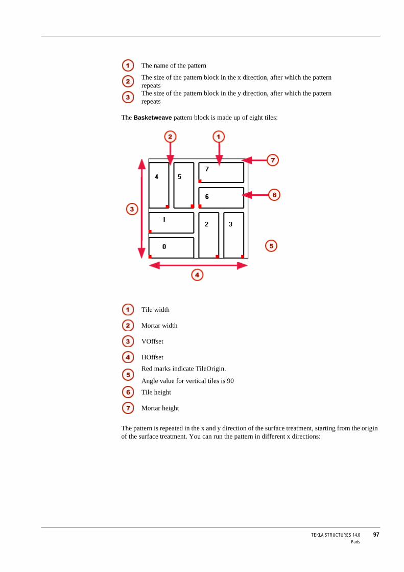
TEKLA STRUCTURES 14.0 97Parts
The Basketweave pattern block is made up of eight tiles:
The pattern is repeated in the x and y direction of the surface treatment, starting from the origin of the surface treatment. You can run the pattern in different x directions:
The name of the pattern
The size of the pattern block in the x direction, after which the pattern repeatsThe size of the pattern block in the y direction, after which the pattern repeats
Tile width
Mortar width
VOffset
HOffset
Red marks indicate TileOrigin.
Angle value for vertical tiles is 90
Tile height
Mortar height

98 TEKLA STRUCTURES 14.0Parts
Defining your own tile patternsXML file To define your own tile patterns:
1. Open the TilePatternCatalog.xml file using any text editor. The file is located in the ..TeklaStructures\*version*\environments\*your_environment*\system folder.
2. Add a new <TilePattern> element to the file. A <TilePattern> element must have <HOffset> and <VOffset> elements and at least one <Tile> element. Other elements are optional. You may find it easier to copy one of the existing elements, then change it suit your needs. See Example pattern definition (p. 94).
The TilePatternCatalog.xml file can contain the following elements:
3. Repeat adding <TilePattern> elements for all the patterns you want to define.
4. Save the TilePatternCatalog.xml file.
Adding surface treatment to parts with cuts and recessesTo force Tekla Structures to consider openings and recesses in parts when adding surface treatment, select the Cut by father part cuts checkbox in the Surface Treatment Properties dialog box:
Element Description
TilePatternCatalog The container for tile patterns. Required.TilePattern Tile pattern element. Required. This element
can contain the following elements listed in this table.
HOffset Horizontal offset of the tile pattern. Required.VOffset Vertical offset of the tile pattern. Required.Tile The individual tiles used in a tile pattern. At
least one required.Color Color of the tile or mortar, defined by the
RGB values (0–255). Optional.Parameter Creates an attribute for any element in the
TilePattern. Optional.Label The label that identifies a parameter in the
dialog box. Optional.TileOrigin The origin of an individual tile, defined from
the origin of the pattern. Optional.

TEKLA STRUCTURES 14.0 99Parts
The green surface treatment has the Cut by father part cuts checkbox selectedThe tiled surface treatment is not cut by the cut in the part: Cut by father part cuts is not selected.

100 TEKLA STRUCTURES 14.0Parts
Surface treatment to cut faces
To add surface treatment to cut faces:
1. Click Detailing > Create Surface Treatment, and then click either To Part Face or To Selected Area on Part Face.
2. Pick the origin of the surface treatment.
3. Pick the direction.
4. Select the cut face on which to apply the surface treatment:
5. For the To Selected Area on Part Face option, pick the points to define the area of the surface treatment.
Cutting surface treatment
To define the cut depth of a polygon cut, for example, to cut thick surface treatment, use the variable XS_POLYGON_CUT_EXTRA_THICKNESS:
1. Click Tools > Advanced options..., and go to the Modeling properties category.2. Set the cut thickness for the variable XS_POLYGON_CUT_EXTRA_THICKNESS. The default
value is 5.0 mm.
Adding surface treatment to chamfered partsTake these things into account when adding surface treatment to chamfered parts:
• Surface treatment does not work on sketched profiles with chamfers.• Add surface treatment before chamfering the part. If surface treatment is applied to a
chamfered part, the surface treatment chamfer cannot be modified later on.
• The chamfers for the main part and surface treatment are separate. Modifying the main part chamfer does not affect the surface treatment chamfer.
• The orientation of unsymmetric chamfers depends on the face where it was created (such as top, bottom, left, or right). To change the orientation of an unsymmetric chamfer, you must swap the chamfer's x and y values.
Creating and editing surface treatment optionsTo create new options in the Surface treatment name list box in the Surface treatment properties dialog box, or to edit existing names, edit the product_finishes.dat file, located in the ..environments\*your_environment*\system folder.
If you use the To All Faces of Part command and select the Cut by father part cuts checkbox, Tekla Structures automatically adds surface treat-ment also to the cut faces.

TEKLA STRUCTURES 14.0 101Parts
The first section of the file defines the available types of surface treatment. Do not edit this section:
The remaining sections define the options for each type of surface treatment. This is where you can edit existing options, or add rows to define new options:
In this example:
• 1 is the surface treatment type (concrete finish)• MF is the code for the surface treatment option
• "Magnesium Float" is the full name of the surface treatment option (remember to enclose the name in double quotes " ")
Here is how this option appears in the dialog box:
See also Adding surface treatment information to report templates (p. 101)
Adding surface treatment information to report templatesYou can include the following surface treatment specific fields in report templates:
// Product finishes// -------------------------//// Type : Type of surfacing// 1 = concrete finish// 2 = special mix// 3 = tile surface// 4 = steel finishes
// =========================================// *** Concrete Finish// =========================================// WET FINISH// ----------1 MF "Magnesium Float"1 SMF "Smooth Magnesium Float"1 WT "Wet Trowel"
Code
Full name
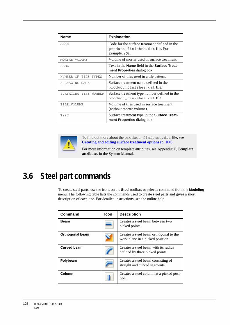
102 TEKLA STRUCTURES 14.0Parts
3.6 Steel part commandsTo create steel parts, use the icons on the Steel toolbar, or select a command from the Modeling menu. The following table lists the commands used to create steel parts and gives a short description of each one. For detailed instructions, see the online help.
Name Explanation
CODE Code for the surface treatment defined in the product_finishes.dat file. For example, TS1.
MORTAR_VOLUME Volume of mortar used in surface treatment.NAME Text in the Name field in the Surface Treat-
ment Properties dialog box.NUMBER_OF_TILE_TYPES Number of tiles used in a tile pattern.SURFACING_NAME Surface treatment name defined in the
product_finishes.dat file.SURFACING_TYPE_NUMBER Surface treatment type number defined in the
product_finishes.dat file.TILE_VOLUME Volume of tiles used in surface treatment
(without mortar volume).TYPE Surface treatment type in the Surface Treat-
ment Properties dialog box.
To find out more about the product_finishes.dat file, see Creating and editing surface treatment options (p. 100).
For more information on template attributes, see Appendix F, Template attributes in the System Manual.
Command Icon Description
Beam Creates a steel beam between two picked points.
Orthogonal beam Creates a steel beam orthogonal to the work plane in a picked position.
Curved beam Creates a steel beam with its radius defined by three picked points.
Polybeam Creates a steel beam consisting of straight and curved segments.
Column Creates a steel column at a picked posi-tion.

TEKLA STRUCTURES 14.0 103Parts
3.7 Concrete part commandsTo create concrete parts, use the icons on the Concrete toolbar, or select a command from the Modeling menu. The following table lists the commands you can use to create concrete parts and gives a short description of each one.
Twin profile Creates a twin profile between two picked points. A twin profile consists of two beams.
Contour plate Creates a contour plate based on picked positions forming a contour.
Command Icon Description
Command Icon Description
Pad Footing Creates a pad footing at a picked posi-tion.
Strip Footing Creates a strip footing that traverses the picked points.
Column Creates a concrete column at a picked position.
Beam Creates a concrete beam between two picked points.
Polybeam Creates a concrete beam consisting of straight and curved segments.
Slab Creates a concrete slab based on picked positions forming a contour.
Panel Creates a concrete panel that traverses the picked points.

104 TEKLA STRUCTURES 14.0Parts

TEKLA STRUCTURES 14.0 105Detailing
4 Detailing
Introduction After you have created a frame of parts in your Tekla Structures model, you will need to complete the model by connecting these parts and adding minor parts and details.
This section explains how to create details (bolts, welds, etc.) using Tekla Structures. It also gives you some techniques for “fine-tuning” part shape and an overview of detailing commands. You can find step-by-step instructions for all these commands in the online help.
Contents This section includes the following topics:
• Bolts (p. 105)• Welds (p. 112)
• Fine-tuning part shape (p. 119)
• Detailing commands (p. 124)
4.1 BoltsIntroduction There are two ways to create bolts:
• Create a single bolt group• Apply a component that automatically creates bolt groups.
This section concentrates on creating single bolt groups. For more information on using components to automatically create bolt groups, see Defining bolts and welds in the Detailing Manual.
You can create different part marks for holes and bolts in drawings.
You cannot use bolt elements (such as screws, washers, and nuts) while you are creating holes, as Tekla Structures uses the same command to create bolts and holes.
Creating assemblies
You can use bolts to create and connect assemblies. You can create nested assemblies by connecting sub-assemblies to an existing assembly, or you can just connect more parts to assemblies using bolts.
Use the Connect part/assembly and Bolt type list boxes in the Bolt properties dialog box to control how Tekla Structures creates assemblies. The order in which you select parts when
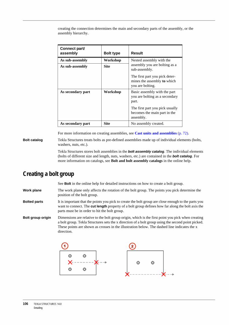
106 TEKLA STRUCTURES 14.0Detailing
creating the connection determines the main and secondary parts of the assembly, or the assembly hierarchy.
For more information on creating assemblies, see Cast units and assemblies (p. 72).
Bolt catalog Tekla Structures treats bolts as pre-defined assemblies made up of individual elements (bolts, washers, nuts, etc.).
Tekla Structures stores bolt assemblies in the bolt assembly catalog. The individual elements (bolts of different size and length, nuts, washers, etc.) are contained in the bolt catalog. For more information on catalogs, see Bolt and bolt assembly catalogs in the online help.
Creating a bolt groupSee Bolt in the online help for detailed instructions on how to create a bolt group.
Work plane The work plane only affects the rotation of the bolt group. The points you pick determine the position of the bolt group.
Bolted parts It is important that the points you pick to create the bolt group are close enough to the parts you want to connect. The cut length property of a bolt group defines how far along the bolt axis the parts must be in order to hit the bolt group.
Bolt group origin Dimensions are relative to the bolt group origin, which is the first point you pick when creating a bolt group. Tekla Structures sets the x direction of a bolt group using the second point picked. These points are shown as crosses in the illustration below. The dashed line indicates the x direction.
Connect part/assembly Bolt type Result
As sub-assembly Workshop Nested assembly with the assembly you are bolting as a sub-assembly.
The first part you pick deter-mines the assembly to which you are bolting.
As sub-assembly Site
As secondary part Workshop Basic assembly with the part you are bolting as a secondary part.
The first part you pick usually becomes the main part in the assembly.
As secondary part Site No assembly created.

TEKLA STRUCTURES 14.0 107Detailing
See also Creating by modifying (p. 107)
Creating by modifyingYou can also create a new bolt group by modifying an existing one. In most cases it is easier to create bolt groups by applying a component including bolt groups, using the following method:
1. Apply a component.2. Explode the component.
3. Modify the bolt group.
Changing bolted partsYou can change which parts a bolt group connects using the command Detailing > Bolts > Edit Bolted Parts. This command prompts you to reselect the main and secondary parts. Tekla Structures automatically updates bolt length to suit these changes. For more information, see Bolt length calculation in the online help.
Creating holesTekla Structures creates holes in the same way as bolts, but you do need to change some of the properties in the Bolt properties dialog box. You can create the following types of holes:
• Round• Oversized
• Slotted
• Tapped
Creating round holesTo create a round hole, follow the steps in Creating a bolt group (p. 106). Tekla Structures calculates the diameter of a round hole as the sum of:
• Bolt size
• Tolerance (hole)
To only create a hole, clear all bolt element checkboxes in the Bolt properties dialog box, as shown below:
Array
• Bold dist X: 150• Bold dist Y: 100xy list
• Bold dist X: 75 175• Bold dist Y: 100 100

108 TEKLA STRUCTURES 14.0Detailing
Creating slotted holesYou also use the Bolt properties dialog box to create slotted holes.
1. Select the checkboxes against Parts with slotted holes to indicate which parts should be slotted.
2. To only create a slotted hole, clear all the Include in bolt assembly checkboxes.
3. Select Slotted in the Hole type list box.
4. Enter the allowance for the slotted hole in the x and y directions of the bolt group using the Slotted hole X or Slotted hole Y fields.
Clean these checkboxes to create a mere hole
Tekla Structures counts the pieces of steel from the head of the bolt down. For example, if you select the second checkbox from the head of the bolt, Tekla Structures slots the second piece of steel from the head of the bolt.
Tolerance
Slotted hole X or Y
Bolt size

TEKLA STRUCTURES 14.0 109Detailing
5. If the bolt connects several parts, you may want to rotate alternate holes by 90 degrees. This allows the bolt to move in different directions. To do this, select Even or Odd in the Rotate slots list box.
Creating oversized holesUse the Bolt properties dialog box to create oversized holes.
1. Select the checkboxes against Parts with slotted holes to indicate which plies of connection get oversized holes.
2. To only create a hole, clear all the Include in bolt assembly checkboxes.
3. Select Oversized in the Hole type list box.
4. Enter the allowance for the oversized hole in the Oversize field. You can also use a negative value to create smaller (tapped) holes.
Bolt group shapeYou have the following options for bolt group shape:
• Array for rectangular• xy list for any shape
• Circle for circular
Tekla Structures uses the values in Bolt dist X and Bolt dist Y to determine how many bolts the bolt group contains, as shown in the table below:
Single bolt To create a single bolt, set Bolt group Shape to Array and enter "0" for both bolt distances.
You indicate the x direction of the bolt group when you create the bolt group (see Creating a bolt group (p. 106)).
Crossing slotted holes to odd or even parts
Parallel slotted holes
Shape Bolt dist X Bolt dist Y
Array Spacing between bolts, in the x direction of the bolt group.
Spacing between bolts, in the y direction of the bolt group.
xy list x coordinate of each bolt, from the bolt group point of origin.
y coordinate of each bolt, from the bolt group point of origin.
Circle Number of bolts. Diameter of the bolt group.
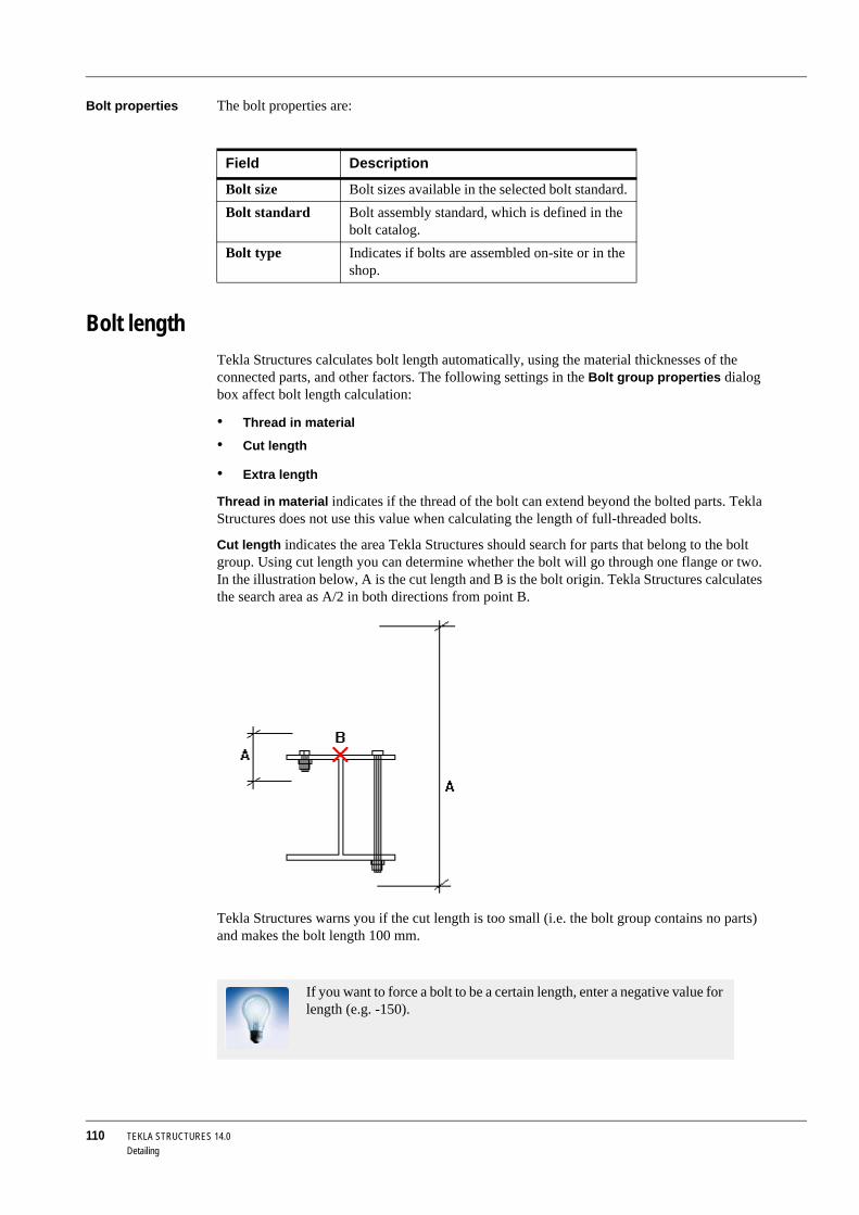
110 TEKLA STRUCTURES 14.0Detailing
Bolt properties The bolt properties are:
Bolt lengthTekla Structures calculates bolt length automatically, using the material thicknesses of the connected parts, and other factors. The following settings in the Bolt group properties dialog box affect bolt length calculation:
• Thread in material
• Cut length
• Extra length
Thread in material indicates if the thread of the bolt can extend beyond the bolted parts. Tekla Structures does not use this value when calculating the length of full-threaded bolts.
Cut length indicates the area Tekla Structures should search for parts that belong to the bolt group. Using cut length you can determine whether the bolt will go through one flange or two. In the illustration below, A is the cut length and B is the bolt origin. Tekla Structures calculates the search area as A/2 in both directions from point B.
Tekla Structures warns you if the cut length is too small (i.e. the bolt group contains no parts) and makes the bolt length 100 mm.
Field Description
Bolt size Bolt sizes available in the selected bolt standard. Bolt standard Bolt assembly standard, which is defined in the
bolt catalog.Bolt type Indicates if bolts are assembled on-site or in the
shop.
If you want to force a bolt to be a certain length, enter a negative value for length (e.g. -150).

TEKLA STRUCTURES 14.0 111Detailing
Using Extra length to increase the material thickness Tekla Structures uses when calculating bolt length. For example, you might need extra bolt length to allow for painting. You can also build additional lengths into bolt assemblies .
See also Bolt catalog
Bolt length calculation
Clash check (p. 134)
Bolt group locationTekla Structures determines the location of the bolt group using the following values:
• Bolt group x axis• Work plane
The two points you pick to create the bolt group determine the bolt group point of origin and its x direction.
Position on plane Position on plane moves the bolt group perpendicular to the bolt group x axis.
Position at depth Position at depth moves the bolt group perpendicular to the current work plane.
Rotation Rotation defines how far the bolt group is rotated around the x axis, relative to the current work plane. For example, you can use this field to indicate on which side of the connected parts you want the bolt head to be.
Offsets You can also use offsets to change the position of the bolt group. Offsets move the bolt group by moving the x axis of the bolt group.
The starting point values Dx, Dy and Dz move the first end of the bolt group, relative to the bolt group x axis. The end point values move the second end of the bolt group.
• A positive Dx value moves the starting point towards the end point.• Dy moves the end point perpendicular to the bolt group x axis on the current work plane.
If there are large gaps between connected parts, the gap is added to the length of the bolt. Tekla Structures calculates bolt length using the the total distance between the first and last surfaces.
Front
Top

112 TEKLA STRUCTURES 14.0Detailing
• Dz moves the end point perpendicular to the current work plane.
Example An example showing the parameters of a bolt group.
Bolts created using the bolt properties:
• Bolt group Shape = Array, Bolt dist X = 100 100, Bolt dist Y = 200• Slotted hole X = 28, Bolt size = 20, Tolerance = 2 (overall dimension = 50)
• Starting point, Dx = 100.0
4.2 WeldsIntroduction To create welds in Tekla Structures, you can:
• Create single welds• Apply components that automatically create welds
Creating assemblies
Tekla Structures forms assemblies based on where the weld should be made. You can create:
• Workshop welds• Site welds
Tekla Structures uses the order in which you select the parts when creating the weld to determine the primary and secondary parts of the assembly. This affects drawings.
The first part you select becomes the primary part of the assembly. Tekla Structures dimensions secondary part(s) relative to the primary part in assembly drawings. The largest primary part in the weld becomes the main part of the assembly.
When you connect assemblies, the first part you select determines the assembly to which you weld sub-assemblies.
Visibility in views To have welds visible in views, open the Display dialog box and set weld visibility to Exact. See Displaying and hiding objects (p. 143). Tekla Structures displays all weld types in a similar way.
Creating weldsYou can create the following types of welds:
The Connect part/assembly setting in the Weld properties dialog box also affects assemblies. See Weld properties (p. 115).

TEKLA STRUCTURES 14.0 113Detailing
• Regular welds. Tekla Structures welds the two parts together using the weld position in the Weld properties dialog box. The length of the weld depends on the length of the connection between the welded parts.
• Polygon welds. You define the exact position of the weld by picking the points you want the weld to traverse.
• Single part welds.
For detailed instructions on how to create welds, see:
Weld symbols in drawingsWeld properties Tekla Structures shows the properties of the weld in the weld symbol in drawings, as shown
below. See also Weld properties (p. 115).
If you move welded parts, polygon welds move with the primary part.
Contour
Weld no Reference text
Size
Type
Weld around
Length
Angle
Finish

114 TEKLA STRUCTURES 14.0Detailing
Reference line and arrow
The weld symbol also contains a reference line and an arrow. The arrow connects the reference line to the arrow side of a connection.
Arrow and other side
When parts are welded together, you can place welds on:
• The arrow sides only• The other sides only
• Both the arrow and other sides
The welds on the arrow and other sides of a part can have different weld properties.
By default, the properties you define for a weld on the arrow side appear above the reference line in drawings. The properties of an other-side weld appear below the reference line in the weld symbol.
Site weld
Pitch (c-to-c spacing)
Lenght
Stitch weld
Effective throat
Root opening
To show the arrow-side weld properties below the reference line in a weld symbol and the other-side properties above, use the variable XS_AISC_WELD_MARK.

TEKLA STRUCTURES 14.0 115Detailing
Weld propertiesThis section describes weld properties.
Size See the image below.
If you enter a zero or negative weld size, Tekla Structures creates the weld, but does not display it drawings.
Type See Weld types (p. 116)
Weld preparation groove angle
When parts are prepared for welding, their edges can be beveled to produce a groove for the weld. This type of weld preparation is commonly used for V-type welds. You can define the angle of bevels and grooves. Tekla Structures displays the angle between the weld type symbol and the fill type contour symbol. For more information on weld preparation, see Weld preparation (p. 119).
Contour The fill type contour of a weld can be:
• None• Flush
• Convex
• Concave
Finish Tekla Structures displays the finish symbol above the weld type symbol in drawings. The options are:
• G (Grind)• M (Machine)
• C (Chip)
Length The length of a regular weld depends on the length of the connection between the welded parts. You can set the exact length of a polygon weld by, for example, defining the start and end points of the weld.
Pitch To create a non-continuous weld, define the center-to-center spacing and the pitch of the welds. Tekla Structures calculates the distance between the welds as the pitch minus the length of the weld.
Root face and RFT
Root face is the height of the narrowest part inside the root opening. The RFT fields in the connection dialog boxes also refer to the root face (thickness).
Size
Root face thickness (RFT)
By default, Tekla Structures uses the character - to separate weld length and pitch, e.g. 50–100. To change the separator to @, for example, set the variable: XS_WELD_LENGTH_CC_SEPARATOR_CHAR=@.

116 TEKLA STRUCTURES 14.0Detailing
Neither root face nor RFT values appear in drawings, but you can use the WELD_ROOT_FACE_THICKNESS field in reports to show the root face dimension in the weld list.
Effective throat Effective throat is the weld size used in weld strength calculation.
Root opening Root opening is the space between the welded parts.
Edge/Around Either one edge (Edge) or the entire perimeter of a face (Around) can be welded. A circle in the weld symbol in drawings indicates the Around option has been used.
Workshop/Site Tekla Structures indicates site welds in the weld symbol using a flag.
Connect part/assembly
Use the Connect part/assembly and Workshop/Site list boxes in the Weld properties dialog box to control how Tekla Structures creates assemblies. The order in which you select parts when creating the connection determines the main and secondary parts of the assembly, or the assembly hierarchy.
See also Cast units and assemblies (p. 72)
Position See Weld position (p. 117).
Stitch To create stitch welds, select Yes in the Stitch weld list box. Stitch welds are staggered on both sides of the part being welded. Tekla Structures shows the weld type symbols as staggered in weld symbols.
User-defined attributes
Create additional properties for welds with user-defined attributes. See Adding properties in the online help.
Reference text and Wtext
To enter additional text for the weld symbol, use the Reference text and Wtext fields. For example, information on the weld specification or process, etc.
Weld typesThe table below shows the available weld types. Some weld types also automatically prepare the parts to be welded. For more information on weld preparation, see Weld preparation (p. 119).
Where weld is to be made (workshop or site), affects assemblies and drawings.
Connect part/assembly
Workshop/Site Result
As sub-assembly Workshop Nested assembly with the assembly you are welding as a sub-assembly.
The first part you pick deter-mines the assembly to which you are welding.
As sub-assembly Site
As secondary part Workshop Basic assembly with the part you are welding as a secondary part.
The first part you pick usually becomes the main part in the assembly.
As secondary part Site No assembly created.

TEKLA STRUCTURES 14.0 117Detailing
Weld positionYou define the position of a weld relative to the work plane. The type and position of the parts to be welded affect the position of the weld.
The options for weld position are:
• x
• y
Weld type Name Number Preparation
None 0 NoFillet weld 10 No
Bevel-groove (single-V butt weld)
3 Both parts
Bevel-groove (single-bevel butt weld)
4 Secondary part
Square-groove (square butt weld)
2 No
Single-V butt weld with broad root face
5 Both edges
Single-bevel butt weld with broad root face
6 Secondary part
U-groove weld (single U-butt weld)
7 Both parts
J-groove weld (single J-butt weld)
8 Secondary part
Flare V-groove weld 16 Both parts
Flare-bevel-groove weld 15 Secondary part
Edge-flange weld 1 No
Corner-flange weld 17 No
Plug weld 11 No
Bevel backing weld 9 No
Spot weld 12 No
Seam weld 13 No
Slot weld 14 No
Partial penetration weld (single-bevel butt + fillet)
18 Secondary part
Partial penetration weld (square groove + fillet)
19 No

118 TEKLA STRUCTURES 14.0Detailing
• z
These can all be in a positive or negative direction. Tekla Structures creates the weld on the face or side of the part that faces in the selected direction (x, y, or z).
See the illustrations below:
If there are no faces that touch in the specified direction, Tekla Structures places the weld relative to the center point of the secondary part.
Secondary part
Main part

TEKLA STRUCTURES 14.0 119Detailing
Weld preparationWhen preparing welds, Tekla Structures bevels the parts to be welded using an anti-material cutting part. Tekla Structures subsequently deletes this cutting part. Tekla Structures displays weld preparations using cyan dash-and-dot lines. Some weld types and connections also automatically prepare the parts to be welded. See Weld types (p. 116).
4.3 Fine-tuning part shapeIntroduction This section describes the various tools you can use to fine-tune the shape of a part.
Assembly main part
Assembly main part
Welding order
secondary
primary
To prevent automatic weld preparation, set the variable XS_DISABLE_WELD_PREP_SOLID=TRUE.

120 TEKLA STRUCTURES 14.0Detailing
ChamferSome part corners can be chamfered. You can use the Chamfer command to shape the following parts: polybeam, contour plate, strip footing, concrete polybeam, concrete slab, and concrete panel.
Tekla Structures creates chamfers using the current properties in the Chamfer Properties dialog box. Click Detailing > Properties > Chamfer... to open the dialog box, or double-click an existing chamfer.
When Tekla Structures creates a part, by default it has a rectangular chamfer at each corner, which does not change the geometry of the part. To change the shape of a part corner:
1. Set the chamfer properties.2. Click Detailing > Create Chamfer.
3. Pick the corner(s) of the part to be chamfered.
See the online help for more information on using this command.
FittingUse the Fitting command to fit the part end to a picked plane. You can use fitting to make part shorter, for example.
Default chamfer
Modified chamfers
We recommend to move part Handles (p. 130) to make the part longer.

TEKLA STRUCTURES 14.0 121Detailing
This command adjusts the end of a beam on a plane, perpendicular to the view plane, which passes through the cutting line you pick. Tekla Structures displays the fitting in the model using a blue fitting symbol. This command has no effect on contour plates.
CutsUse cut to shape parts. Cut is not meant for cutting the entire part end. Either move part Handles (p. 82) or use the Fitting (p. 120) command instead.
You can create the following types of cuts for a part:
• Line cut• Polygon cut
• Part cut
Line cut A line cut shapes end of the beam or column.
Line cut cuts the end of a beam on a plane, perpendicular to the view plane, which passes through the cutting line you pick. Tekla Structures displays the cut in the model using a blue cut symbol.
Fitting symbol

122 TEKLA STRUCTURES 14.0Detailing
By default, line cuts do not affect beam length in NC files. To change this, see Fittings affect NC datathe online help.
See the online help for more detailed information on using this command.
Polygon cut This command cuts a part using a polygon. Tekla Structures displays the cut using dot-dash lines. You must create cuts in a plane view.
See online help for more detailed information on using this command.
Part cut This command creates an anti-material cutting part. Tekla Structures does not delete the original cutting part. An anti-material part only cuts the selected main part. Tekla Structures displays the anti-material part using dot-dash lines.
You can cut parts that already have cuts. For example, you can cut anti-material parts to create more sophisticated cut shapes.
Exact representation (without symbol)
Fast representation (Cut symbol)
Exact representation (without symbol)
Fast representation
Polygon-shaped cut
You should always define the polygon so that there is some tolerance between the edges. If the edge of a cutting polygon is in exactly the same position as the edge of the part to be cut, it can be unclear whether the edge should be cut away.
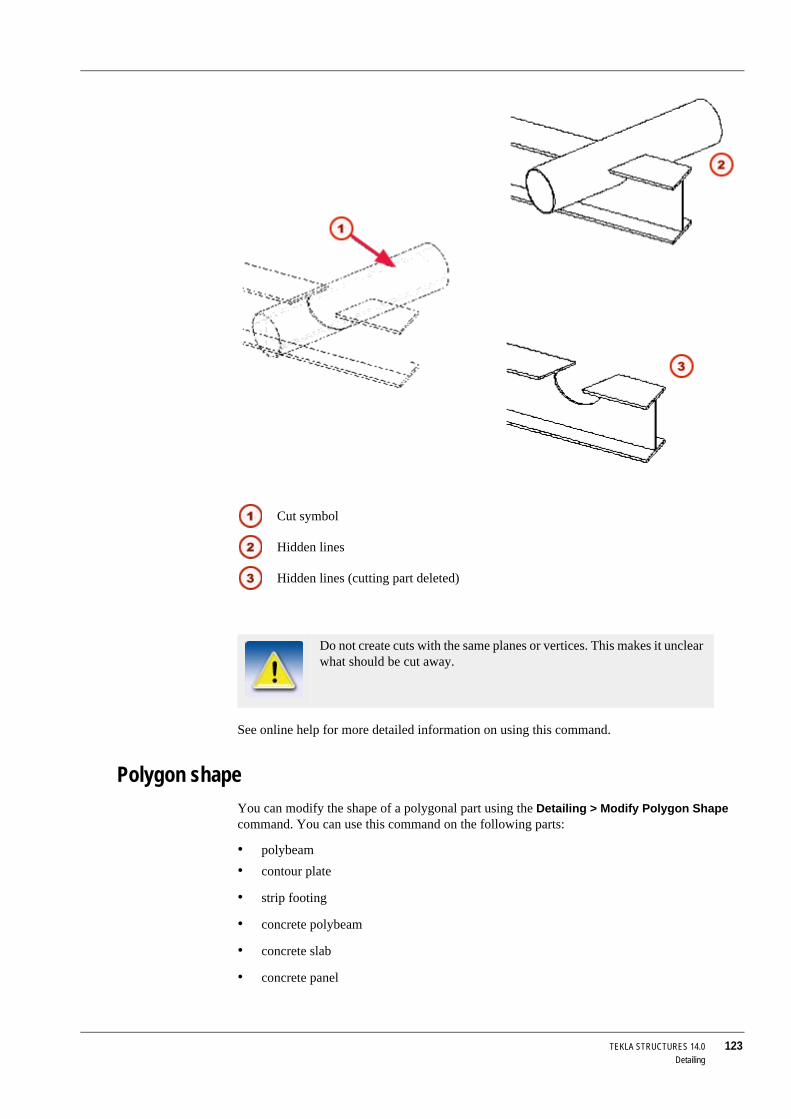
TEKLA STRUCTURES 14.0 123Detailing
See online help for more detailed information on using this command.
Polygon shapeYou can modify the shape of a polygonal part using the Detailing > Modify Polygon Shape command. You can use this command on the following parts:
• polybeam• contour plate
• strip footing
• concrete polybeam
• concrete slab
• concrete panel
Cut symbol
Hidden lines
Hidden lines (cutting part deleted)
Do not create cuts with the same planes or vertices. This makes it unclear what should be cut away.

124 TEKLA STRUCTURES 14.0Detailing
See the online help for more information on using this command.
4.4 Detailing commandsTo fine-tune or detail your model, use the icons on the Detailing and Steel toolbars, or select commands from the Detailing menu. The following table lists the commands for detailing and gives a short description of each one.
Detailing command Icon Description
Create Bolts Creates a bolt group in a part/parts.
Edit Bolted Parts Changes the parts a bolt group connects.
See Changing bolted parts (p. 107).Create Weld between Parts
Creates a weld between two parts.
Create Polygon Weld Welds parts together using a polygon.
Create Weld to Part Creates a weld to a part without connecting any other parts.
Prepare Part for Welding
Prepares the parts to be welded.
Create Chamfer Chamfers part corners.
Fit Part End Creates a fitting to a part.
Cut Part > With Line Cuts the end of a beam on a plane, perpendicular to the work plane, which passes through the picked line.
Cut Part > With Polygon Cuts a part using a polygon.
Cut Part > With Another Part
Cuts a part with another part.
Modify Polygon Shape Modifies the shape of a polygonal part.

TEKLA STRUCTURES 14.0 125Settings and Tools
5 Settings and Tools
In this chapter This chapter explains the ways in which you can manipulate models and change program settings. It also describes how to use many of the tools in Tekla Structures.
Contents It is divided into the following sections:
• Examining the model (p. 125)• Querying objects (p. 132)
• Copying and moving objects (p. 138)
• Displaying and hiding objects (p. 143)
• Filter (p. 152)
• Settings (p. 161)
• Numbering (p. 168)
• Tools (p. 177)
• Settings and tools reference (p. 192)
5.1 Examining the modelIntroduction This section describes a variety of tools you can use to view your model by changing its position
and orientation within the view window. It also covers flying through the model.
Zoom commandsThe zoom tools allow you to focus in on a particular area, or pull out for a wider view. You can use a mouse, or keystrokes, or a combination of both. You use the majority of these tools within an existing view. However, a zoom window must be open to use the Magnifier and Pan tools.
The Zoom commands are:
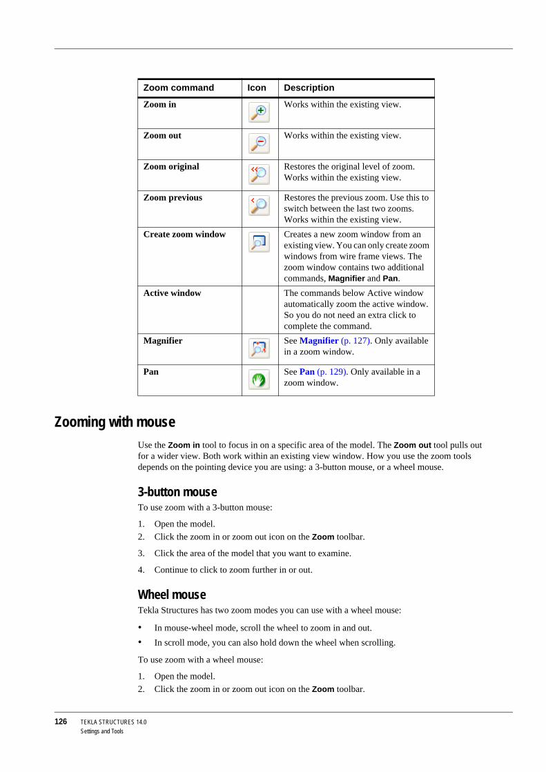
126 TEKLA STRUCTURES 14.0Settings and Tools
Zooming with mouseUse the Zoom in tool to focus in on a specific area of the model. The Zoom out tool pulls out for a wider view. Both work within an existing view window. How you use the zoom tools depends on the pointing device you are using: a 3-button mouse, or a wheel mouse.
3-button mouseTo use zoom with a 3-button mouse:
1. Open the model.2. Click the zoom in or zoom out icon on the Zoom toolbar.
3. Click the area of the model that you want to examine.
4. Continue to click to zoom further in or out.
Wheel mouseTekla Structures has two zoom modes you can use with a wheel mouse:
• In mouse-wheel mode, scroll the wheel to zoom in and out.• In scroll mode, you can also hold down the wheel when scrolling.
To use zoom with a wheel mouse:
1. Open the model.2. Click the zoom in or zoom out icon on the Zoom toolbar.
Zoom command Icon Description
Zoom in Works within the existing view.
Zoom out Works within the existing view.
Zoom original Restores the original level of zoom. Works within the existing view.
Zoom previous Restores the previous zoom. Use this to switch between the last two zooms. Works within the existing view.
Create zoom window Creates a new zoom window from an existing view. You can only create zoom windows from wire frame views. The zoom window contains two additional commands, Magnifier and Pan.
Active window The commands below Active window automatically zoom the active window. So you do not need an extra click to complete the command.
Magnifier See Magnifier (p. 127). Only available in a zoom window.
Pan See Pan (p. 129). Only available in a zoom window.

TEKLA STRUCTURES 14.0 127Settings and Tools
3. Click the area of the model that you want to examine.
4. Scroll forward to zoom in, scroll backward to zoom out.
Using keystrokesTo zoom using keystrokes:
1. Open the model.2. With the mouse cursor over the model, press Page Up to zoom in, Page Down to zoom out.
Zoom settingsCentered zooms To keep the center point of the view in the middle of the view window, regardless of the position
of the pointer, check Centered zooms on the Setup menu.
If Centered zooms is not checked, the pointer does not move.
Zoom ratio The following variables control how much you zoom in or out with each click.
3-button mouse Use the variable XS_ZOOM_STEP_RATIO to control the zoom ratio when using a 3-button mouse. The default value is 0.25. Increase this value to zoom in or out more with each click.
Wheel mouse See also Wheel mouse (p. 126). To set the zoom ratio when scrolling (not holding down) the wheel, use the variable XS_ZOOM_STEP_RATIO_IN_MOUSEWHEEL_MODE.
To set the zoom ratio when scrolling and holding down the wheel, use the variable XS_ZOOM_STEP_RATION_IN_SCROLL_MODE.
Creating a zoom windowOpening a zoom window gives you access to additional tools, the Magnifier (p. 127) and Pan (p. 129). These appear on the toolbar within the zoom window.
To create a zoom window:
1. In the View Properties dialog box, click Wire frame in the View type list box.2. Click Modify.
3. Click View > Zoom > Create Zoom Window.
4. Click a starting corner for the zoom window, then drag the pointer to size the window. Release the mouse button to create the window.
5. Move the zoom window to a convenient location on the screen.
6. Resize the zoom window by dragging the window boundaries.
MagnifierThe Magnifier is useful when you need to keep a general view of the model open, and examine particular areas in detail, at the same time.
To use theMagnifier, you must have both a general view window containing the model and a zoom window open. See Creating a zoom window (p. 127).
You can only create zoom windows from wire frame views.

128 TEKLA STRUCTURES 14.0Settings and Tools
Click the Magnifier icon in the zoom window. As you move the pointer in the general view, the zoom window displays the area around the pointer in detail, as shown in the example below. Change the level of magnification by zooming in and out in the zoom window.
Moving the model in the view windowIn Tekla Structures you can move, pan, rotate or fly through a model, in the view window.
MoveThe Move commands move the viewpoint (or camera) rather than the model itself. Use the up, down, left and right arrows on the keyboard to move the viewpoint. You can also click View > Move to use the move commands.
Center by cursor To center the model on a particular point, click View > Move > Center by Cursor, then click anywhere in the view to center the view on that point.

TEKLA STRUCTURES 14.0 129Settings and Tools
PanThe Pan command moves the model itself. Activate dynamic panning using the P key on your keyboard, or click View > Move > Pan. The pointer will change to a hand. Click and drag the mouse to move the model anywhere within the view window.
You can also pan while using the Fly command. To do this, activate the Fly command, and use the middle mouse button to pan when needed.
See also Flying through the model (p. 130)
Rotating the modelYou can use keystrokes, menu commands, the mouse, or a combination of these techniques to rotate the model.
Rendered view In rendered views, you can rotate the model around the existing center of rotation. Hold down the Ctrl key and click and drag with the middle mouse button.
To relocate the center of rotation:
1. Press the V key.2. Click to pick the new center of rotation.
Or:
1. Use the keystrokes Ctrl+R.2. Click to pick the new center of rotation.
3. Click and drag with the left mouse button to rotate the model.
4. Use the Esc key or Interrupt to end rotation.
Keyboard technique
You also have the following keyboard options to rotate the model around the existing center of rotation:
Wire frame In wire frame view, you can only use the keyboard technique to rotate a model. The center of rotation is fixed in the center of the work area.
Automatic rotation
Click View > Rotate. You have the following options:
Click Esc to stop rotation.

130 TEKLA STRUCTURES 14.0Settings and Tools
Disable view rotation
To disable or enable view rotation, click Window > Rotate > Disable view rotation, or use F8.
Flying through the modelIn Tekla Structures, you can travel through a model, changing direction and varying speed as you go.
Start flyingTo fly through a model, you must have a rendered view open, with Projection set to Perspective. See View properties for more infromation on how to change view properties. Use the keyboard shortcut Shift+F to start flying though the model, or click View > Fly.
Pick the view to fly in.Tekla Structures displays an arrow symbol to indicate the flying direction.
See also View properties
Stop flyingUse Interrupt to stop flying. See Ending commands (p. 42).
Adjust speedTo adjust your flying speed, move the mouse to the desired flying direction. The flying speed grows exponentially when you are approaching the model from a distance.
Change directionTo fly forward, move the mouse forward. To change the flying direction, move the mouse to the desired direction.
Changing the level of flying1. To change the level you are flying on and to go straight up or down, hold down the Ctrl
key and move the mouse forward to go up, and backwards to go down. Release the Ctrl key to continue flying on a level.
Changing the camera angle1. To change the camera angle, scroll with the mouse wheel. To fly in the in the direction of
the camera angle, hold down the Shift key and scroll forwards to go down or backwards to go up.
Creating clip planesIn Tekla Structures, you can create up to six clip planes in any rendered model view. Using clip planes enables you to focus in on the required detail in the model.
To create a clip plane:
1. Select a rendered model view.
Snap switches affect model rotation. For example, with Free active, you can click anywhere to define the center of rotation. If Free is inactive, you need to pick an intersection point, or the end of a part. See also Specifying points (p. 33).

TEKLA STRUCTURES 14.0 131Settings and Tools
2. Start the Create clip plane command:
• Right-click and select Create clip plane from the pop-up menu, or• Click View > Create clip plane.
3. To select the position of the clip plane, click a plane.
4. To finish, right-click and select Interrupt.
5. The clip plane symbol appears in the model:
• To move the clip plane, click the symbol, and drag it to a new location.
• To delete a clip plane, click the clip plane symbol and press Delete.
Selected plane
Clip plane symbol

132 TEKLA STRUCTURES 14.0Settings and Tools
5.2 Querying objectsIntroduction This section describes the various tools in Tekla Structures that you can use to query the
properties of your model.
InquireThe Inquire tool displays the properties of a particular object, or group of objects, within the model. Click Tools > Inquire, and then pick an object in the model to access the following options:
MeasureUse the Measure tool to measure angles, the distance between two points and between bolts. All measurements are temporary.
Option Action
Object Displays the properties of the object.Center of gravity Tekla Structures creates a point at the center of
gravity of the picked part(s) and displays informa-tion on the center of gravity in a separate window.
Welded parts Highlights the selected part and all the parts that are welded to it.
Primary Welded Part Highlights the primary part when you select a secondary part.
Assembly Objects Highlights all the parts in the same assembly or cast unit as the selected part. See also Checking contents (p. 72).
Component Objects Highlights the objects that form part of the selected component.
Phases... Displays the object properties of the different phases in the model, in a separate window.
Model size... Displays the quantity of all object quantities of the current model, in a separate window.
To display the properties of a part, assembly, or cast unit using a custom-ized report template when you use the Tools > Inquire > Object command, modify the following templates to suit your needs:
• TS_Report_Inquire_Part.rpt (for parts)• TS_Report_Inquire_Assembly.rpt (for assemblies)
• TS_Report_Inquire_Cast_Unit.rpt (for cast units)
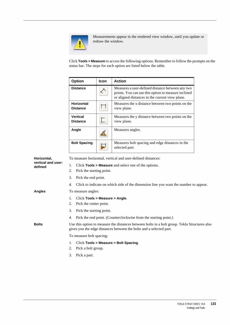
TEKLA STRUCTURES 14.0 133Settings and Tools
Click Tools > Measure to access the following options. Remember to follow the prompts on the status bar. The steps for each option are listed below the table.
Horizontal, vertical and user-defined
To measure horizontal, vertical and user-defined distances:
1. Click Tools > Measure and select one of the options.2. Pick the starting point.
3. Pick the end point.
4. Click to indicate on which side of the dimension line you want the number to appear.
Angles To measure angles:
1. Click Tools > Measure > Angle.2. Pick the center point.
3. Pick the starting point.
4. Pick the end point. (Counterclockwise from the starting point.)
Bolts Use this option to measure the distances between bolts in a bolt group. Tekla Structures also gives you the edge distances between the bolts and a selected part.
To measure bolt spacing:
1. Click Tools > Measure > Bolt Spacing.2. Pick a bolt group.
3. Pick a part.
Measurements appear in the rendered view window, until you update or redraw the window.
Option Icon Action
Distance Measures a user-defined distance between any two points. You can use this option to measure inclined or aligned distances in the current view plane.
Horizontal Distance
Measures the x distance between two points on the view plane.
Vertical Distance
Measures the y distance between two points on the view plane.
Angle Measures angles.
Bolt Spacing Measures bolt spacing and edge distances in the selected part.

134 TEKLA STRUCTURES 14.0Settings and Tools
See also XS_VIEW_FREE_MEASURE_PLANE
Clash checkWhen you have completed your model, run the Clash check to find parts, bolts, or reference model objects that collide.
Steps 1. Select the objects you want to check.2. Click Tools > Clash check.
3. The clash check progress is displayed in the status bar. You can continue working during the clash check.
If there are no colliding parts, Tekla Structures displays the message No collisions detected on the status bar.
If parts, bolts, or reference model objects collide, Tekla Structures highlights them in yellow and displays the clash check log in the List dialog box.
If you start clash checking while another clash check is still running, you can choose whether to continue checking, restart the operation and check the currently selected parts, or stop checking.
4. To quickly locate and view colliding parts in the model, select the line containing the ID numbers of colliding parts from the list. Tekla Structures highlights the parts in the model. Hold down the F key while you do this to have Tekla Structures fit the work area.
Set bolt clearance
To define bolt clearance for clash checking, click Tools > Options > Options... > Clash check. Enter the values in the Bolt clash check settings dialog box.
Clashes of objects that are only touching one another are not included in the clash check log.

TEKLA STRUCTURES 14.0 135Settings and Tools
The clash checking clearance area is grey. Select the checkbox in front of the field if you want to use the clearance value. If you clear the checkboxes, the clearance will be zero.The clearance in front of the bolt head is equal to the bolt length.
If you do not enter values for clearances, Tekla Structures uses the default value of 1.00.
You need to save the clearance values to use them in future sessions. Click Tools > Defaults > Save Defaults.
If Tekla Structures cannot find the bolt head or nut diameter in the bolt catalog, it uses the shank diameter.
Reference models
The following reference model file types are supported in clash checking:
• IFC• DWG
• DGN
CompareUse this tool to compare two assemblies or parts.
d is the larger value of the bolt head or nut diameters
Clash check clearence
If you are working on a large model, running the clash check may some-times be slow. In that case you can use the old clash checking function-ality, which does not recognize clashes with reference models.
For more information, see XS_USE_NEW_CLASH_CHECK and XS_CLASH_CHECK_BETWEEN_REFERENCES.

136 TEKLA STRUCTURES 14.0Settings and Tools
To compare parts, select two parts in the model. Click Tools > Compare > Parts.
To compare assemblies, click on a part in each assembly. Click Tools > Compare > Assemblies.
Tekla Structures displays the results on the status bar.
Part labelsUse the Part label option to display selected part properties, user-defined attributes, and template attributes in a model view:
To use the Part label option in a model view:
1. Double-click the view to open the View properties dialog box.2. Click Display.... The Display dialog box appears.
3. Click the Advanced tab and select the Part label checkbox.
If you need more detailed information on assemblies or parts, use Inquire (p. 132).

TEKLA STRUCTURES 14.0 137Settings and Tools
To add a property to the part label:
1. Select a property on the Properties list.2. Click Add to add it to the Part label list.
To add a user-defined attribute or template attribute to the part label:
1. Select User-defined attribute on the Properties list.2. Click Add. The Part label dialog box appears:
3. Enter the attribute name and click OK.
For more information on the Display dialog box, see Display in the online help.
Finding distant objectsWhen the work area is huge, the model may contain some distant objects that are not easy to find. Use the Find Distant Objects command to find these objects.
To find distant objects:
You cannot use this command to find parts (such as beams, columns or plates).

138 TEKLA STRUCTURES 14.0Settings and Tools
1. Click Tools > Diagnose & Repair Model > Find Distant Objects.Tekla Structures displays a list of object IDs.
2. Select an object in the list.
3. Right-click and select a command from the pop-up menu.
You can, for example, inquire or delete the object.
See also XS_DISTANT_OBJECT_FINDER_TOLERANCE
5.3 Copying and moving objectsUse the Copy and Move tools to copy and move objects linearly, with rotation, or with mirroring.
Copy creates a new object, leaving the existing object in its original position. Move relocates the existing object. Copy Special and Move Special provide additional options for copying and moving objects.
You can also move the view plane of a selected view. When you move a view, Tekla Structures only uses the vector perpendicular to the view plane.
Limitations Tekla Structures does not mirror connection properties, so Mirror does not fully mirror objects if they include connections that contain, for example, asymmetrically positioned parts.
Duplicate objects When you copy or move objects, Tekla Structures checks for duplicate objects in the location where you are about to copy or move the objects to. Tekla Structures also checks for duplicates if you create new parts in the same location with an existing part.
Use the variable XS_DUPLICATE_CHECK_LIMIT_FOR_COPY_AND_MOVE to define the maximum number of objects that are checked for duplicates while copying or moving objects.
If duplicates are found, you can choose whether to keep or delete the duplicate objects.
CopyTo create copies of selected object(s):
1. Select the objects to copy.2. Click the Copy icon, or click Edit > Copy.
3. Pick the origin for copying.
Tekla Structures considers two objects duplicates if they have the same orientation and the same size of bounding box.
This functionality does not apply to objects that you copy by using a modeling tool, such as the Array of Objects (29) component.

TEKLA STRUCTURES 14.0 139Settings and Tools
4. Pick one or more destination points.
The objects are copied immediately.
5. To stop copying, click Edit > Interrupt.
See also Copy Special (p. 141)
I f you click Edit > Undo, the latest copy operation is undone, but the Copy command remains active.
Tekla Structures copies all objects connected to the objects you copy. Tekla Structures also tries to copy connections. Connections must be surrounded by similar parts to be copied successfully.

140 TEKLA STRUCTURES 14.0Settings and Tools
MoveTo move selected object(s) to a new position:
1. Select the objects to move.2. Click the Move icon, or click Edit > Move.
3. Pick the origin for moving.
4. Pick the destination point.
The objects are moved immediately. The Move command does not remain active.
To move selected object(s) to a new position at a specified distance:
1. Select the objects to move.2. Click Edit > Move.
3. Pick the origin for moving.
4. Move the cursor in the direction you want to move the objects, but do not pick the point.
5. Type in the distance.
When you start typing, Tekla Structures displays the Enter a numeric location dialog box automatically.
6. Click OK.

TEKLA STRUCTURES 14.0 141Settings and Tools
See also Move Special (p. 141)
Moving the view plane (p. 56)
Copy SpecialThe Copy Special command provides additional options for copying objects.
1. Select the objects you want to copy.2. Click Edit > Copy Special.
You have the following options:
See also Copy (p. 138)
Move SpecialThe Move Special command provides additional options for moving objects.
1. Select the objects you want to move.2. Click Edit > Move Special.
Tekla Structures also moves the objects connected to the objects you move. For example, if you move points, Tekla Structures also moves the parts or assemblies that use those points.
Command Icon Description
Linear... Creates copies of selected object(s) at a speci-fied distance from the original.
Rotate... Creates copies of selected object(s), either rotated around a line you specify on a work plane, or around the work plane z axis.
Mirror... Creates a mirrored copy of selected object(s) through a plane you specify.
To Another Plane Creates a copy of selected object(s) on another plane, which you specify by picking three points.
To Another Object
Copies selected objects(s) from an object to other, similar objects.
From Another Model...
Creates a copy of model objects in phases you specify.
Tekla Structures copies all objects connected to the objects you copy. Tekla Structures also tries to copy connections. Connections must be surrounded by similar parts to be copied successfully.

142 TEKLA STRUCTURES 14.0Settings and Tools
You have the following options:
See also Move (p. 140)
Drag and DropYou can move and copy objects using drag-and-drop.
1. Click Tools > Options > Drag and Drop to activate it.2. Select the object to move or copy.
3. You have the following options:
Command Icon Description
Linear... Moves selected object(s) to a new position at a specified distance from the original.
Rotate... Rotates selected object(s) either around a line you specify on a work plane, or around the work plane z axis.
Mirror... Mirrors selected object(s) using a line you specify.
To Another Plane Moves selected object(s) to another plane, which you specify by picking three points.
To Another Object
Moves selected object(s) from an object to another, similar object.
Tekla Structures also moves the objects connected to the objects you move. For example, if you move points, Tekla Structures also moves the parts or assemblies that use those points.
To move the part, drag it to the new position
To copy the part, hold down the Ctrl key and drag it to the new position
To move the part end, click the handle and drag it to the new position

TEKLA STRUCTURES 14.0 143Settings and Tools
5.4 Displaying and hiding objectsThe visibility of objects in views depends on the following settings:
• work area• view depth
• view setup
• view filter
• object representation settings
Work area and view depth are like two virtual boxes. Objects which have their center line partially or totally inside both boxes are visible. Newly created objects are visible also outside the view depth but never outside the work area. Redrawing a view only shows the objects inside the view depth (for redrawing, see also Refreshing the screen display (p. 60).
Object visibility To define which objects are visible and how they are displayed in a view:
1. Double-click the view. 2. In the View properties dialog box, click Display.... The Display dialog box appears.
3. Set the visibility and representation for different object types and for components.
For information on advanced view settings and different display options, see Display in the online help. See also View type (p. 57)).
For more information on hiding lines, see Hide lines (p. 181) and for information on hiding selected parts, see Hide parts (p. 182).
Object representation
To create customized presentation of objects, use object representation settings. For more information on using the Object representation dialog box, see Object representation settings (p. 143).
Filtering objects To more precisely define which objects are displayed in a view, use the view filter:
1. Double-click the view.2. In the View properties dialog box, click Object group....
3. Use the Object Group - View Filter dialog box to define which objects are displayed in the view.
See also View filter (p. 152) and Filter (p. 152).
Object representation settingsUse object representation settings to modify the color and transparency of objects in the model view and create customized presentation of defined object groups.
For example, the following images show the same model with different object representation settings:

144 TEKLA STRUCTURES 14.0Settings and Tools
Topics Creating object representation settings (p. 144)
Colors (p. 145)
Transparency (p. 146)
Object representation files (p. 146)
Creating object representation settingsTo create new representation settings:
1. Click View > Representation > Object representation....The Object Representation dialog box has the following buttons:
Standard object representation:
Only parts with profile name starting with IPE* or HEA* are visible:
Objects with user-defined attribute Planned erection date set to 01/05/2006 are displayed in blue, while all other parts are 90% transparent.
Button Description
Add row, Delete row Use to specify the coloring and visibility of several object groups.
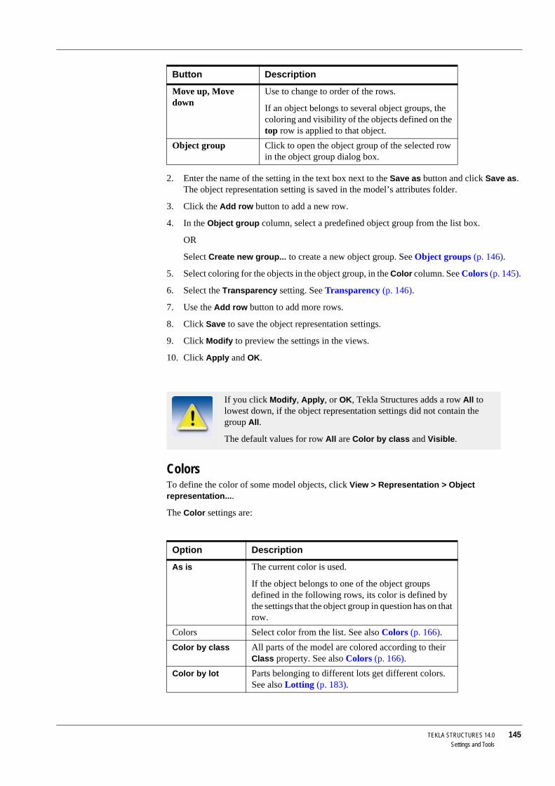
TEKLA STRUCTURES 14.0 145Settings and Tools
2. Enter the name of the setting in the text box next to the Save as button and click Save as. The object representation setting is saved in the model’s attributes folder.
3. Click the Add row button to add a new row.
4. In the Object group column, select a predefined object group from the list box.
OR
Select Create new group... to create a new object group. See Object groups (p. 146).
5. Select coloring for the objects in the object group, in the Color column. See Colors (p. 145).
6. Select the Transparency setting. See Transparency (p. 146).
7. Use the Add row button to add more rows.
8. Click Save to save the object representation settings.
9. Click Modify to preview the settings in the views.
10. Click Apply and OK.
ColorsTo define the color of some model objects, click View > Representation > Object representation....
The Color settings are:
Move up, Move down
Use to change to order of the rows.
If an object belongs to several object groups, the coloring and visibility of the objects defined on the top row is applied to that object.
Object group Click to open the object group of the selected row in the object group dialog box.
If you click Modify, Apply, or OK, Tekla Structures adds a row All to lowest down, if the object representation settings did not contain the group All.
The default values for row All are Color by class and Visible.
Option Description
As is The current color is used.
If the object belongs to one of the object groups defined in the following rows, its color is defined by the settings that the object group in question has on that row.
Colors Select color from the list. See also Colors (p. 166).Color by class All parts of the model are colored according to their
Class property. See also Colors (p. 166).Color by lot Parts belonging to different lots get different colors.
See also Lotting (p. 183).
Button Description

146 TEKLA STRUCTURES 14.0Settings and Tools
TransparencyThe Transparency settings are:
For color settings, see Colors (p. 145).
Object representation filesTekla Structures saves object representation settings with filename extension *.rep in the current model’s attributes folder.
• You can copy the object representation setting file to another model’s attributes folder.• To make the object representation setting available to all models, copy the file to the system
folder.
Tekla Structures searches for the object representation files in the standard search order. For more information, see Folder search order in the online help.
Object groupsObject groups are sets of rules with which you can group objects by selected properties and conditions. Use the object groups:
• In view filter, to define which objects are displayed in the selected view. • In select filter, to define which objects can be selected.
• In the Object Representation dialog box, to control the transparency and coloring of objects in all views.
Color by phase Parts belonging to different phases get different colors. See also Phases (p. 164).
Color by analysis type
Displays parts according to the member analysis type. See also Member analysis type in the Analysis Manual.
Color by analysis utility check
Displays parts according to the utilization ratio in anal-ysis. See also Viewing analysis results in the Analysis Manual.
Color by attribute Displays parts in different colors according to the values of a user-defined attribute.
Option Description
As is The current visibility.
If the object belongs to any object group for which the visibility and color settings have been defined, the settings will be read from that object group.
Visible Object is shown in the views.50% transparent Transparent in rendered view. 70% transparent
90% transparent
Hidden Does not show in the views.
Option Description

TEKLA STRUCTURES 14.0 147Settings and Tools
• In the Project Status Visualization tool.
Topics Creating object groups (p. 147)
Object group files (p. 147)
Creating object groupsTo create a new object group:
1. Click View > Representation > Object Representation... to open the dialog box.2. Select Create new group... in the list box in the Object group column, and the Object
group - representation dialog box opens.
3. Enter the name of the object group and click Save as.
• The object group you create is saved in the model’s attributes folder. See Object group files (p. 147).
4. Click Add row to define a rule.
• Rule is based on selected Category, Property, Condition, and Value.• See Object group rules (p. 148) for more information on creating rules.
5. Use the Add row button to add rows for more rules. Use the Delete row and Delete all buttons when needed.
6. When the set of rules is ready, click Save.
7. Click Close.
8. The new object group is shown in the Object representation dialog box.
Object group filesFilenames Tekla Structures saves object group representation files with filename extension *.PObjGrp.
Tekla Structures has three different object group types: view filter, selection filter, and object representation. All these use different object group files, so you cannot, for example, use selection filter object groups in the view filter.
Filename extension
Object group filename extensions depend on the purpose the group was created for:
File location Object groups are saved in the current model’s attributes folder.
• To make an object group available in another model, copy its file to the attributes folder of the destination model.
• To make an object group available in all models, copy its file to the system folder.
You must restart Tekla Structures to apply the changes.
Tekla Structures searches for the object group files in the default order. For more information, see Folder search order in the online help.
Filename exten-sion Created in dialog box
*.PObjGrp Object group - representation*.VObjGrp Object group - view filter*.SObjGrp Object group - select filter

148 TEKLA STRUCTURES 14.0Settings and Tools
Deleting an object group
To delete an object group, delete the object group representation file located in the attributes folder.
See also Displaying and hiding objects (p. 143)
Object representation settings (p. 143)
Object group rules (p. 148)
Object group rulesIn the object group dialog box, you can add, delete, and modify the rules on which the object group is based.
The object group rules include the following options:
A consistent naming policy for created object groups is important, as handling the object group files is done manually in the model, project, firm, and system folders.
Column Options Description
Checkboxes Select the checkbox to include the row in the rule. By default each new row is disabled.
Parentheses • empty • ( )
• (( ))
• ((( )))
Use parentheses to create nested rules.
Category • Part
• Component
• Bolt
• Weld
• Reinforcing bar
• Assembly
• Load
• Object
Use the Object category with user-defined attributes or, for example, if you need to create a selection filter based on ID numbers.
Property Various properties, depending on the selected category.
You can use most of the available properties in the object group rules. All user-defined attributes are selectable too.
Condition Various conditions to define the rules.
Numeric, textual, and date proper-ties all have different set of condi-tions.

TEKLA STRUCTURES 14.0 149Settings and Tools
To add a rule:
1. In the object group dialog box, click Add row.2. Select Category from the list box.
3. Select Property from the list box.
4. Select Condition.
5. Enter the value in the Value column, or select the value from the model.
6. Add more rows and use And/Or column and parentheses to create more complex rules.
Using dates in the object group rulesTo use date rules in the object groups:
1. Open the Object group - representation dialog box and add a row to the group.2. Select, for example, Object in the Category column.
3. Select, for example, user-defined attribute Actual erection date in the Property column.
4. Select Condition. With date properties, you can use the following conditions:
• Equals
• Does not equal
• Later than
• Later than or equal
• Earlier than
• Earlier than or equal
5. In the Value column, click Select date... to open the Select date dialog box.
The dialog box includes the following options:
Value Enter the value manu-ally.
Enter the value to define the rule. You can use wildcards in the Value column. See Using wild-cards (p. 160).
Select date... See Using dates in the object group rules (p. 149).
Select from model... Select the value from the model by picking the object.
For example, if you chose Part as Category, and Name as Property, by clicking a part in the model, you get its Name property in the object group rule.
And/Or • empty (= And)• And
• Or
Use the And/Or column when you create rules with several rows.
An empty field is the same as if it had the And option selected.
Column Options Description
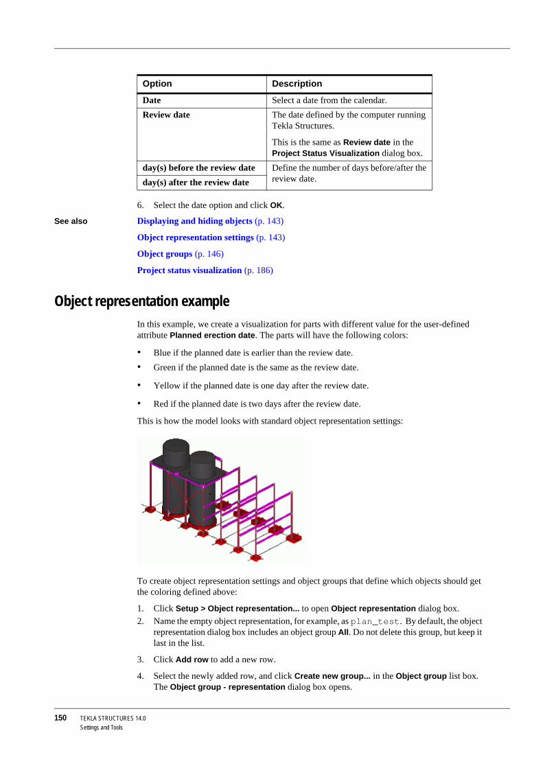
150 TEKLA STRUCTURES 14.0Settings and Tools
6. Select the date option and click OK.
See also Displaying and hiding objects (p. 143)
Object representation settings (p. 143)
Object groups (p. 146)
Project status visualization (p. 186)
Object representation exampleIn this example, we create a visualization for parts with different value for the user-defined attribute Planned erection date. The parts will have the following colors:
• Blue if the planned date is earlier than the review date. • Green if the planned date is the same as the review date.
• Yellow if the planned date is one day after the review date.
• Red if the planned date is two days after the review date.
This is how the model looks with standard object representation settings:
To create object representation settings and object groups that define which objects should get the coloring defined above:
1. Click Setup > Object representation... to open Object representation dialog box.2. Name the empty object representation, for example, as plan_test. By default, the object
representation dialog box includes an object group All. Do not delete this group, but keep it last in the list.
3. Click Add row to add a new row.
4. Select the newly added row, and click Create new group... in the Object group list box. The Object group - representation dialog box opens.
Option Description
Date Select a date from the calendar. Review date The date defined by the computer running
Tekla Structures.
This is the same as Review date in the Project Status Visualization dialog box.
day(s) before the review date Define the number of days before/after the review date.day(s) after the review date

TEKLA STRUCTURES 14.0 151Settings and Tools
5. Enter a name for the group, for example, plan_before_review_date.
6. Click Save as.
7. Modify the rule. This rule includes objects that have user-defined attribute Planned erection date set earlier than the review date.
• Select Object in the Category column.• Select Planned erection date in the Property column.
• Select Earlier than in the Condition column.
• Click Select date... in the Value list box and select Review date in the Select date dialog box and click OK.
8. Click Save and Close.
9. In the Object representation dialog box, select blue in the Color list box of the plan_before_review_date row and check that the object group is set to Visible.
Repeat steps 3 to 9 and create three more object groups with different rules:
• Object group plan_review_date, with the following rule: Object Planned erection date Equals Review date.
• Object group plan_one_day_after, with the following rule: Object Planned erection date Equals 1 day(s) after the review date.
• Object group plan_two_days_after, with the following rule: Object Planned erection date Equals 2 day(s) after the review date.
For more information on creating rules with dates, see Using dates in the object group rules (p. 149).
10. When all object groups are created, set the color and visibility of the object groups, in the Object representation dialog box, to be the following:
11. Select Hidden in the Transparency column for the All object group and check that it is last in the list.
12. Click Save and Modify.
The model is now shown with the defined colors:

152 TEKLA STRUCTURES 14.0Settings and Tools
See also Object representation settings (p. 143)
Object groups (p. 146)
Object group rules (p. 148)
Project status visualization (p. 186)
5.5 FilterIntroduction The Filter option is useful when you want to perform an operation on several objects or
properties at the same time.
This section describes the Selection and View filters.
• Use the Selection Filter to avoid making errors when selecting objects. • Use the View Filter to define which objects appear in each view. This is particularly useful
for complicated models containing a large number of objects.
View filterUse the View filter to define which objects are displayed in a view, according to object properties. Work area, view depth, view setup, and the object representation settings also affect whether an object is visible. See Displaying and hiding objects (p. 143).
To display the View filter dialog box:
1. Double-click the view to open the View properties dialog box, or click View > View Properties....
2. Click the Object group... button.
The view and selection filters are based on the object group functionality. Fore more information, see Object groups (p. 146).

TEKLA STRUCTURES 14.0 153Settings and Tools
Selection filterUse the Selection Filter to define which objects can be selected. Tekla Structures also contains several switches that control whether you can select an object (see Controlling the selection (p. 38)).
Selection filter dialog boxTo display the Object Group - Selection Filter dialog box:
• Click the Selection Filter icon , or• click Edit > Selection Filter....
To use the Selection Filter on an object, the object must be visible in the relevant view. See View filter (p. 152) for more information.

154 TEKLA STRUCTURES 14.0Settings and Tools
Use object properties to define whether or not an object can be selected.
To use the Selection Filter dialog box that was available in previous versions, set the variable XS_USE_OLD_FILTERING to TRUE.
See also XS_USE_OLD_FILTERING
Standard selection filtersTekla Structures contains several standard selection filters. The selection filter list box on the Selecting toolbar lists both standard and user-defined filters.
Using the variable XS_USE_OLD_FILTERING affects only the appear-ance of the dialog box. Internally Tekla Structures uses the new filters in all filtering.

TEKLA STRUCTURES 14.0 155Settings and Tools
To apply a filter, select one from the list. Standard filters always appear first on the list.
Converting old selection filtersThe selection filter list box is divided into two parts:
• New selection filters (file extension .SObjGrp), which you can use in selection filtering• Old filters (file extension .msf)

156 TEKLA STRUCTURES 14.0Settings and Tools
When you select an old filter, Tekla Structures automatically converts it to a new filter and saves the new filter. The old filter is then removed from the list box.
Defining your own filtersTo define your own filters:
1. Click the Selection Filter icon , or click Edit > Selection Filter... to open the Object Group - Selection Filter dialog box.
2. Find a filter which has close to the same settings as you need.
3. Modify the settings, then enter a new name in the Save as field.
4. Click Save as, then OK to exit. You can now choose the new filter from the dropdown list.
Examples The Selection Filter is very useful when using the drawing wizard to automatically create drawings. For example, if you only want to produce drawings of the beams in the model, use the Selection Filter to select them.
Use the Selection Filter to select the parts you want to carry loads.
To have the filters you define appear at the top of the list, right after the standard filter, use capital letters in the filter name.

TEKLA STRUCTURES 14.0 157Settings and Tools
Filtering techniquesFilter by multiple properties
You can define filters containing several properties. You can also have multiple filtering values for each property. If you use multiple values, separate the strings with blank spaces (for example, 12 5). If a value consists of multiple strings, enclose that particular value in quotation marks (for example, "custom panel").
By using conditions, parentheses, and the And/Or option you can create filters that can be as complex as needed.
Set filtering on To set filtering on for a particular property, select the corresponding checkbox. The checkboxes define which rows of the filter are enabled and effective. In the following example, only the second row affects filtering:
Complement filtering
To use complement filtering (in other words, defining which parts not to select), select Does not equal in the Condition column.
Template properties
You can select objects according to template properties. To do this, select Template in the Category column, and then select the desired property in the Property column.
When you create rules between objects that represent different categories, use the And option when possible to avoid potential problems with more complex rules.

158 TEKLA STRUCTURES 14.0Settings and Tools
Assembly types If the category you have selected is Assembly, the property you have selected is Assembly type, and you use the option Select from model... in the Value column, Tekla Structures returns the value as a number. The number indicates the type of assembly in question. The following table lists the numbers and the corresponding assembly types:
See also Using wildcards (p. 160)
Filtering examplesBeams and columns
To create a selection filter for beams and columns:
1. Click Add row twice to add two new rows. 2. Fill in the part names, BEAM and COLUMN.
3. Select the Or option. The filter is now looking for an object that has the Name BEAM or COLUMN.
4. Enter the filter’s name next to the Save as button, and click Save as.
In the Object Group - Selection Filter dialog box, use the following units for template properties, even when using the US Imperial environment:
• mm for lengths• mm2 for areas
• kg for weights
• degree for angles
To check which units Tekla Structures uses for certain template proper-ties, use the Select from model... option in the Value column.
ValueAssembly type
0 precast 1 cast in place2 steel3 timber6 miscellaneous
To select the value directly from the model, click Select from model... and pick an object.
The same result is accomplished if you write BEAM COLUMN in the Value column in the first row. If you use multiple values, you must sepa-rate the strings with blank spaces.

TEKLA STRUCTURES 14.0 159Settings and Tools
Phases To create a selection filter for all parts in phases 1 and 2:
1. Click Add row. 2. Fill in the part phases, 1 and 2. Separate the strings with a blank space.
3. Enter the filter’s name next to the Save as button, and click Save as.
Complement filter If you only want to select certain parts, use complement filter to filter out the remaining parts.

160 TEKLA STRUCTURES 14.0Settings and Tools
To create a filter that selects all parts except for those with the profile BL200*20:
1. Click Add row. 2. Fill in the profile, BL200*20.
3. In the Condition column, select Does not equal.
4. Enter the filter’s name next to the Save as button, and click Save as.
Using wildcardsYou can use wildcards to shorten filter strings. A wildcard is a symbol that stands for one or more characters. Tekla Structures uses the following wildcards:
Select switches also affect the selection of objects. See Controlling the selection (p. 38).
Wildcard Description Example
* (asterisk) Matches any number or characters
HE* matches all parts with a profile name that begins with the characters "HE".
You can also this symbol at the beginning of a word: *BRAC*.

TEKLA STRUCTURES 14.0 161Settings and Tools
Filter in dialog boxesThe Filter also appears in many dialog boxes. In a Filter field you can enter characters from the name of the object you are looking for, and then click the Filter button to find the matching names. See also Using wildcards (p. 160).
5.6 SettingsIn this section This section explains how to modify various settings in Tekla Structures.
Units and decimalsTo configure how units and decimals are input, output, stored and displayed, click Tools > Options > Options... > Units and decimals.
Update When you click OK in the Units and decimals dialog box, Tekla Structures updates the format of units and decimals in all open dialog boxes.
Input and output data
Different types of data are separated onto three tabs in the Units and decimals dialog box. Input data appears on the Modeling and Catalogs tabs. Output data appears on the Analysis results tab (output data only relates to structural analysis).
? (question mark) Matches a single char-acter
HE?400 matches parts with profile names such as HEA400, HEB400, and HEC400
[ ] (square brackets) Matches whatever is enclosed in the brackets
L[78]X4X1/2 matches parts with the profile names L7X4X1/2 and L8X4X1/2
The characters * and ? can also be used in object names. If the object name you want to filter contains * or ?, enclose * or ? in square brackets. E.g., to find the profile P100*10, enter P100[*]10 in the filter field.
Wildcard Description Example

162 TEKLA STRUCTURES 14.0Settings and Tools
Modeling func-tions
The settings on the Modeling tab affect the data you use when using modeling commands, such as copy, move, create grid, create point, part location, and dimensions.
Catalogs Settings on the Catalogs tab affect the data stored in the profile and material catalogs.
No effect Settings in the Units and Decimals dialog box have no effect on drawings, reports, or the Inquire and Measure tools.
The decimal point symbol is always a period (.). It cannot be changed.
Exponent nota-tion
You can use positive exponent notation, but not negative exponent notation.
Imperial unitsYou can input length in imperial units in the following ways:
• Inches in decimals (e.g. 300.5")• Feet in decimals (e.g. 62.7')
• Fractional notation (e.g. 60'-6")
Fractional notation
In fractional notation, all input is shown in feet (') and inches (").
If you are using imperial units and want to use fractions, you must use fractional notation.
The number of decimals affects input and storage accuracy. Always use a sufficient number of decimals.

TEKLA STRUCTURES 14.0 163Settings and Tools
Mouse and pointer settingsYou can configure your mouse and pointer settings to suit the way you work using:
• Pan (p. 163)• Drag and drop (p. 163)
• Xmouse (p. 163)
• Xsnap (p. 164)
• Rollover highlight (p. 164)
PanPan toggles the function of the middle mouse button between panning and scrolling. To switch between scrolling and panning, click Tools > Options > Middle Button Pan, or press Shift+M. Scrolling moves the “viewer”, and panning moves the model. Hold down the middle button and drag the pointer away from the origin of the object. To scroll faster, drag the pointer farther from the origin mark; drag closer to slow down. You can use Scroll and Pan when other commands are active.
Drag and dropWith Drag and drop active, you can use drag and drop to move or copy parts. You can also modify polygon shape using drag and drop. You cannot drag and drop components, component parts, bolts, or welds.
Activate To toggle Drag and drop on and off, use the keystroke D, or Tools > Options > Drag and Drop. It remains active until you switch it off.
Tekla Structures remembers this setting between sessions by user name.
Smart Select With both Drag and Drop and Smart Select active, you can drag and drop handles without selecting them first.
To toggle SmartSelect on and off, use the keystroke S, or select Tools> Options > Smart Select. It remains active until you switch it off.
Tekla Structures remembers this setting by session and user name.
XmouseWith Xmouse active, moving the pointer over a view activates the view. Without Xmouse you have to click on a view to activate it. To toggle Xmouse on or off, click Tools > Options > Xmouse. A checkmark appears next to the menu option if Xmouse is already active.
Using Xmouse Xmouse is useful when you are using two views that partly overlap. See the following examples:
• If you want to pick beam positions from two overlapping views, with Xmouse active you simply move the pointer over the view to activate it.
• With Xmouse active, you can also use the Page Up, Page Down and arrow keys in overlapping views, without having to click a view to activate it first. See Moving the model in the view window (p. 128).
To avoid accidentally dragging and dropping parts, de-activate drag and drop when you are not using it.
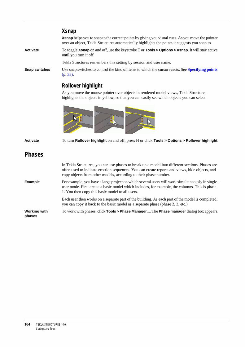
164 TEKLA STRUCTURES 14.0Settings and Tools
XsnapXsnap helps you to snap to the correct points by giving you visual cues. As you move the pointer over an object, Tekla Structures automatically highlights the points it suggests you snap to.
Activate To toggle Xsnap on and off, use the keystroke T or Tools > Options > Xsnap. It will stay active until you turn it off.
Tekla Structures remembers this setting by session and user name.
Snap switches Use snap switches to control the kind of items to which the cursor reacts. See Specifying points (p. 33).
Rollover highlightAs you move the mouse pointer over objects in rendered model views, Tekla Structures highlights the objects in yellow, so that you can easily see which objects you can select.
Activate To turn Rollover highlight on and off, press H or click Tools > Options > Rollover highlight.
PhasesIn Tekla Structures, you can use phases to break up a model into different sections. Phases are often used to indicate erection sequences. You can create reports and views, hide objects, and copy objects from other models, according to their phase number.
Example For example, you have a large project on which several users will work simultaneously in single-user mode. First create a basic model which includes, for example, the columns. This is phase 1. You then copy this basic model to all users.
Each user then works on a separate part of the building. As each part of the model is completed, you can copy it back to the basic model as a separate phase (phase 2, 3, etc.).
Working with phases
To work with phases, click Tools > Phase Manager.... The Phase manager dialog box appears.

TEKLA STRUCTURES 14.0 165Settings and Tools
The following table explains how to use the buttons in the Phases dialog box.
Additional properties
You can add more phase properties, which will appear as extra columns on the list. Tekla Structures considers phase properties to be user-defined attributes, so you can define the names of phase properties in the objects.inp file. See Adding properties. To use phase properties in reports and templates, use the syntax PHASE.ATTRIBUTE_NAME in the phase property field name.
Button Description
Filter Lists the phases by the number and/or name criteria you enter. See Filter in dialog boxes (p. 161).
Set current Makes the selected phase the current phase. Tekla Structures assigns all objects you create after setting a phase to current to the current phase. The @ character in front of the phase number indicates the current phase.
Select by objects Highlights the phases associated with the objects currently selected in the model. Use this button to iden-tify the phase of an object.
Add Creates a new phase.Delete Deletes the phases you select from the list.Select by phase Selects and highlights the corresponding objects in the
model if you have selected associated phases on the list.
Modify phase Changes the phases of the selected objects to the phase selected on the list.
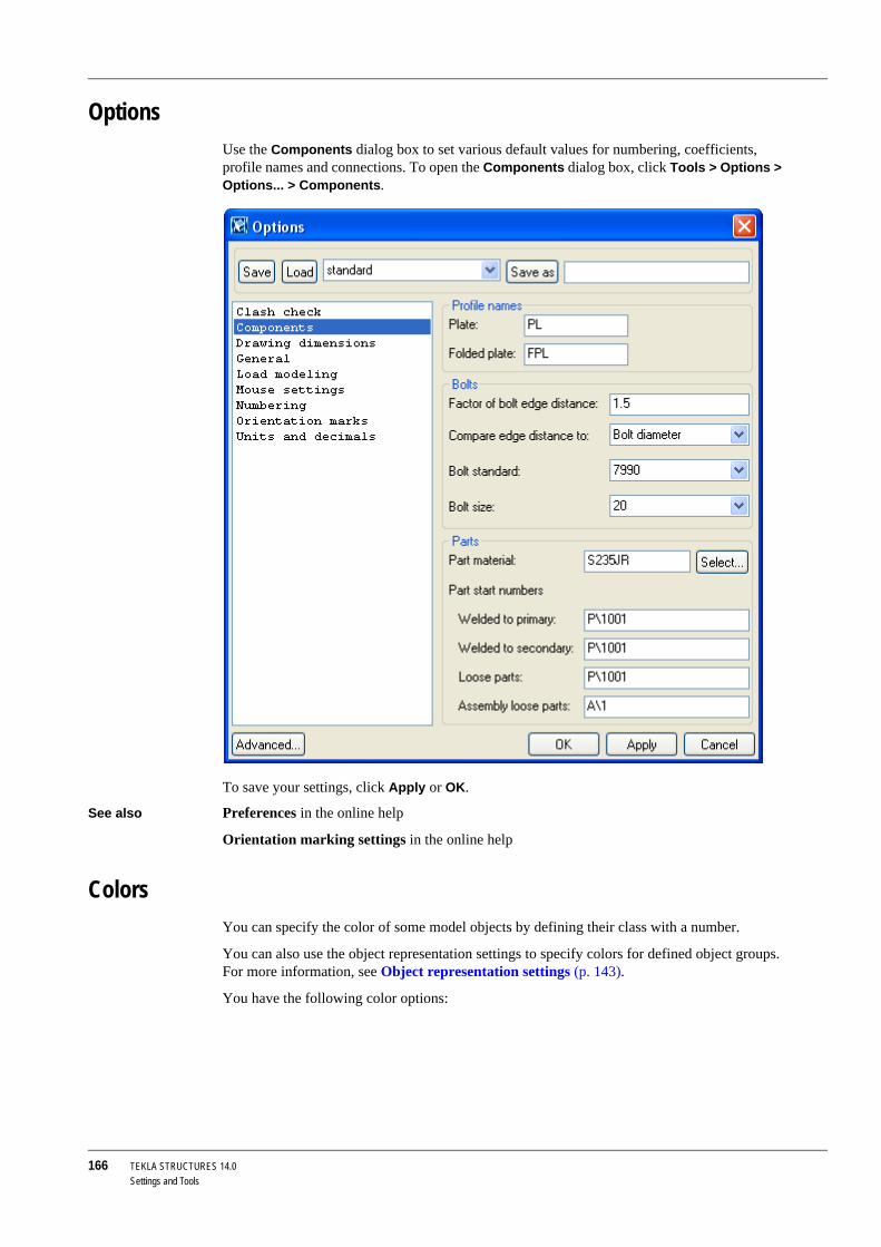
166 TEKLA STRUCTURES 14.0Settings and Tools
OptionsUse the Components dialog box to set various default values for numbering, coefficients, profile names and connections. To open the Components dialog box, click Tools > Options > Options... > Components.
To save your settings, click Apply or OK.
See also Preferences in the online help
Orientation marking settings in the online help
ColorsYou can specify the color of some model objects by defining their class with a number.
You can also use the object representation settings to specify colors for defined object groups. For more information, see Object representation settings (p. 143).
You have the following color options:

TEKLA STRUCTURES 14.0 167Settings and Tools
You may also need to use the numbers of colors with some variables, for example XS_CLASH_CHECK_COLOR. For more information, see the online help.
General settingsTekla Structures also includes the following general settings:
Snap gridUse Snap grid when picking a point using the Snap to any position snap switch. See Specifying points (p. 33). To define a snap grid, click Tools > Options > Options... > Mouse settings.
Enter the following information:
Color Number
black
light gray or white 1
red 2 or 0
bright green 3
blue 4
cyan 5
yellow 6
magenta 7
gray 8
pink 9
lime 10
aqua 11
lilac 12
orange 13
light blue 14
Field Description
Activate snap grid when free snap is on
Check to make the snap grid active.
Spacing x, y Snap grid spacingOrigin dx, dy Offsets for grid origin

168 TEKLA STRUCTURES 14.0Settings and Tools
BeepWith this switch active, Tekla Structures warns you with a beep when an error occurs. Click Tools > Options > Beep to toggle this switch on and off.
5.7 NumberingThis section explains how to change numbering settings and apply numbering in Tekla Structures.
Numbering settingsTo open the Numbering Setup dialog box, click Drawings & Reports > Numbering > Numbering Settings...:

TEKLA STRUCTURES 14.0 169Settings and Tools
You can use various numbering options:
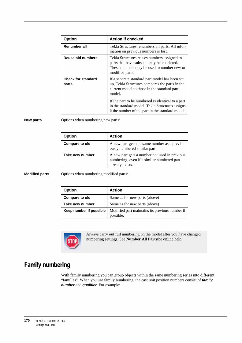
170 TEKLA STRUCTURES 14.0Settings and Tools
New parts Options when numbering new parts:
Modified parts Options when numbering modified parts:
Family numberingWith family numbering you can group objects within the same numbering series into different “families”. When you use family numbering, the cast unit position numbers consist of family number and qualifier. For example:
Option Action if checked
Renumber all Tekla Structures renumbers all parts. All infor-mation on previous numbers is lost.
Reuse old numbers Tekla Structures reuses numbers assigned to parts that have subsequently been deleted. These numbers may be used to number new or modified parts.
Check for standard parts
If a separate standard part model has been set up, Tekla Structures compares the parts in the current model to those in the standard part model.
If the part to be numbered is identical to a part in the standard model, Tekla Structures assigns it the number of the part in the standard model.
Option Action
Compare to old A new part gets the same number as a previ-ously numbered similar part.
Take new number A new part gets a number not used in previous numbering, even if a similar numbered part already exists.
Option Action
Compare to old Same as for new parts (above)Take new number Same as for new parts (above)Keep number if possible Modified part maintains its previous number if
possible.
Always carry out full numbering on the model after you have changed numbering settings. See Number All Partsthe online help.

TEKLA STRUCTURES 14.0 171Settings and Tools
• The family number is the same for assemblies and cast units which match the criteria you define in the Numbering setup dialog box.
• Assemblies or cast units which have the same family number but different exact geometry or materials get unique qualifier numbers.
See also Assigning family numbers for series (p. 171)
Assigning family numbers for parts (p. 173)
Assigning family numbers for seriesOn the Family numbering tab, you can assign family numbers for series.
For example, the following two beams both have the numbering series prefix B:
The beams are otherwise similar, but the connections used are different.
To assign family numbering for the series:
Usage 1. Click Drawings & Reports > Numbering > Numbering Settings... to open the Numbering Setup dialog box.
2. On the Family numbering tab, click Add series to open the Add series dialog box, which lists all the assembly and cast unit numbering series in the model.
Family number
Qualifier
Assembly position: B/1
Assembly position: B/2

172 TEKLA STRUCTURES 14.0Settings and Tools
3. Select the numbering series B/1 and click Add. The numbering series appears in the family numbering list.
4. Use the Compare section of the dialog box to define what to compare for the numbering series. Define the compare criteria for each numbering series separately.a Select at least one checkbox, but not all of them.b If you select all checkboxes, the family number will be the same as the normal
assembly position, and the qualifier number will be 1 for all. If you do not select any checkboxes, only one family number per series is assigned.
5. Click Apply or OK.6. Update the numbering in the model.7. Tekla Structures assigns the beams family numbering.
Result Tekla Structures considers beams different according to the compare criteria you defined, and they get different family numbers:

TEKLA STRUCTURES 14.0 173Settings and Tools
Assigning family numbers for partsTo assign a family number and/or family qualifier for parts:
Usage 1. Select the objects whose family numbers you want to change.2. Click Drawings & Reports > Numbering > Change Number > Family Number....3. In the Assign Family Number dialog box, enter the desired values in the Family number
and Family qualifier fields.4. Click Assign.
Assembly position numbersYou can sort the order in which assemblies are given their position numbers. To do this, use the options in the Numbering Setup dialog box:
You can sort the position numbers in ascending or descending order.
Assembly position: B/1-1
Assembly position: B/2-1

174 TEKLA STRUCTURES 14.0Settings and Tools
The sort order can be based on the following criteria:
• The x, y or z coordinates of the main part of the assembly.• The user-defined attribute of an assembly.
• The user-defined attribute of the main part.
If your sorting is based on user-defined attributes, Tekla Structures displays a list box that includes all the available user-defined attributes.
See also Numbering Settings...
Numbering examplesPart numbers This example explains how different numbering settings result in different part numbers when
you modify a part.
1. Create three identical beams with the numbering series prefix P and start number 1.2. Number the model. All the beams have the part position number P1.
3. Modify one of the beams.
4. Number the model. You should now have two beams P1 and one P2.
5. Change beam P2 to be identical to the others.
6. Number the model.
Tekla Structures assigns different part position numbers to this part, according to which numbering settings you used, as follows:
• Compare to old: P1• Keep number if possible: P2
• Take new number: P3
Project phases When you start modeling a project, the required numbering settings may be totally different from what they are after the project has been issued for the first time and you start revising the model.
When sorting by x, y or z coordinates, the sorting is based on the center of gravity of the reference axis.
Sorting by user-defined attributes or by location does not affect the part position.
If you add new parts, already numbered objects are not renumbered to suit the sorting order by, for example, the x coordinate. In this case you should renumber the parts.

TEKLA STRUCTURES 14.0 175Settings and Tools
To control numbering settings on different phases of the project, create pre-defined numbering settings for the different phases of the project. Save the settings with the Save as button.
For example:
• Phase 1 - Stick modelingDoing only modeling before any drawings are released. At this stage you may even want to select Renumber all, or at least Re-use old numbers.
• Phase 2 - Drawing issue
When the first set of drawings is issued, but modeling continues, you may want to minimize the effects to already issued drawings. You can do this for example by selecting Keep number if possible in the Modified list box.
• Phase 3 - Revisions
At some point the project is more or less finalized, and any changes to the model should be handled in a different way than before. You may want to take a new number for all modified parts, not comparing them to any of the existing parts. To do this, select Take a new number in the Modified list box.
Applying numberingWhen you apply numbering, Tekla Structures assigns marks to parts and assemblies. Numbering is carried out according to the settings in the Numbering Setup dialog box (see Numbering settings (p. 168)).
Pop-marking Pop-marking for NC files also affects numbering. When pop-marking is activepop-marks, Tekla Structures will assign different numbers to identical parts if they have different pop marks.
Example Two main parts in different assemblies are identical, apart from a difference in the position of the plates welded to them. In this case, Tekla Structures assigns them different numbers.
Interrupt numbering
You can safely interrupt numbering before it is complete by clicking Cancel in the dialog box Tekla Structures displays while it is running. If you interrupt numbering, parts and assemblies retain their original numbers.
Log file Click Tools > Display Log File > Numbering History... for a report showing the numbering history.
Applying num-bering
To apply numbering, click Drawings & Reports > Numbering. You have the following options:
When you reach the next step in a project, you can load pre-defined settings, and then save them as standard. This way the standard settings are always automatically loaded from that point on when someone opens the model.
For information on how to interpret the log file, see Log files in the online help.

176 TEKLA STRUCTURES 14.0Settings and Tools
Assigning control numbers to partsControl numbers are properties that identify the location of parts in a model. Use the Create control numbers (S9) macro to assign control numbers to parts. You can have Tekla Structures assign consecutive control numbers to all parts in the model, to selected parts, or only to parts in a specific numbering series. Each part gets a unique control number.
To display control numbers in drawings, reports, or when you use the Tools > Inquire > Object command, select the property, ACN.
For more information on how to use this tool, see the online help.
See also To find out how to display control numbers in drawings, see User-defined attributes in marks in the Drawing Manual.
Locking and unlocking control numbers (p. 176)
Locking and unlocking control numbersTo prevent Tekla Structures from renumbering the control numbers of all parts in the model, or of specific parts, use the Lock/Unlock control numbers tool.
To lock or unlock control numbers:
1. Click Drawings & Reports > Numbering > Lock/Unlock control numbers:
Option Result
Number Modified Objects Assigns marks to all modified and new parts and assemblies.
Number All Parts Assigns marks to all parts and assem-blies.
Change Number Changes final position number.Clear Numbers Deletes position numbers.Save Preliminary Numbers Saves current part position number as
preliminary marks for selected parts.Assign Control Numbers... Assigns control numbers to parts. Lock/Unlock Control Numbers Locks or unlocks control numbers. See
Locking and unlocking control numbers (p. 176).
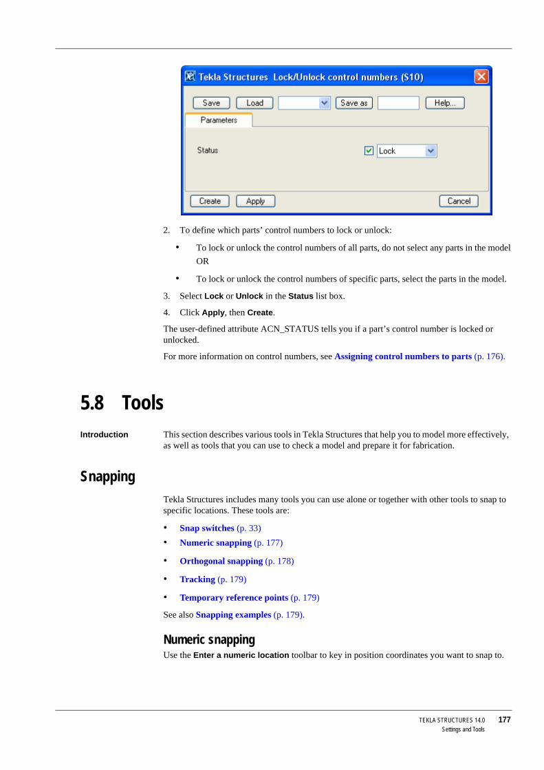
TEKLA STRUCTURES 14.0 177Settings and Tools
2. To define which parts’ control numbers to lock or unlock:
• To lock or unlock the control numbers of all parts, do not select any parts in the modelOR
• To lock or unlock the control numbers of specific parts, select the parts in the model.
3. Select Lock or Unlock in the Status list box.
4. Click Apply, then Create.
The user-defined attribute ACN_STATUS tells you if a part’s control number is locked or unlocked.
For more information on control numbers, see Assigning control numbers to parts (p. 176).
5.8 ToolsIntroduction This section describes various tools in Tekla Structures that help you to model more effectively,
as well as tools that you can use to check a model and prepare it for fabrication.
SnappingTekla Structures includes many tools you can use alone or together with other tools to snap to specific locations. These tools are:
• Snap switches (p. 33)• Numeric snapping (p. 177)
• Orthogonal snapping (p. 178)
• Tracking (p. 179)
• Temporary reference points (p. 179)
See also Snapping examples (p. 179).
Numeric snappingUse the Enter a numeric location toolbar to key in position coordinates you want to snap to.

178 TEKLA STRUCTURES 14.0Settings and Tools
To display the toolbar, initiate a command that requires you to pick positions, and then do one of the following:
• Start entering the coordinates using the keyboard.• Click Tools > Enter a Numeric Location and select an option. To access additional options,
click Tools > Options > Shortcuts > Enter a Numeric Location.
The following table explains the types of information you can enter.
After you enter the coordinates, press Enter or click OK to snap to the position.
Snapping mode Tekla Structures has two snapping modes, relative and absolute. Use the variable XS_KEYIN_DEFAULT_MODE to indicate the default snapping mode.
See also XS_KEYIN_ABSOLUTE_PREFIX
XS_KEYIN_RELATIVE_PREFIX
Orthogonal snappingUse the shortcut O (Tools > Ortho) to snap to positions in orthogonal directions on the work plane (0, 45, 90, 135, 180 degrees, etc.).
To control orthogonal snapping, use the variables XS_SEMI_ORTHO_ANGLE and XS_USE_SEMI_ORTHO. For more information, see Appendix C, Variables, in the System Manual.
You can enter Description/Example Special character
Cartesian coordinates The x, y, and z coordinates of a position separated by commas, e.g. 100,-50,-200.
, (comma)
Polar coordinates A distance, an angle on the xy plane, and an angle from the xy plane separated by angle brackets, e.g. 1000<90<45.
Angles increase in the coun-terclockwise direction.
<
Absolute coordinates The coordinates based on the origin of the work plane.
Set with the variable XS_KEYIN_ABSOLUTE_PREFIX
Relative coordinates The coordinates relative to the last position picked, e.g. @1000,500 or @500<30.
Set with the variable XS_KEYIN_RELATIVE_PREFIX
One value A distance to an indicated direction.
Two coordinates If you omit the last coordi-nate (z) or angle, Tekla Struc-tures assumes that the value is 0.
In drawings, Tekla Structures ignores the third coordinate.
Three coordinates

TEKLA STRUCTURES 14.0 179Settings and Tools
TrackingTracking means that you follow a line and pick a point at a specified distance along the line. You usually use tracking in combination with other snapping tools, such as snap switches, or orthogonal and numeric snapping. See also Snapping examples (p. 179).
Temporary reference pointsYou can create a temporary reference point to use as a local origin when snapping in models or drawings.
1. Initiate a command that requires you to pick positions.2. Hold down the Ctrl key and pick a position. A green cross indicates that this position is now
a temporary reference point.
3. Use this temporary reference point with snap tools to define directions and distances.
See also Snapping examples (p. 179).
Snapping examplesWhen you have snap switches on and you use a command that requires you to pick positions, the mouse pointer locks onto a snap point. Tekla Structures displays a magenta line between the last point picked and the snap point.
You can track along the line towards a snap point, and use the Enter a numeric location toolbar to specify the distance from the last point picked.
You can also track along an orthogonal direction. See Orthogonal snapping (p. 178).
In the illustration below, we snapped to a grid line midpoint and tracked along the tentative line for 1000 units.

180 TEKLA STRUCTURES 14.0Settings and Tools
You can also track beyond the snap point, for example, 4000 units from the last point picked.
Track in the opposite direction by entering a negative value, for example, -1000.
Reference points In this example, we create a beam using a grid line midpoint as a temporary reference point and tracking along an orthogonal direction (shown as green dashed line) for 500 units. Click OK, and Tekla Structures creates the beam along the magenta line.

TEKLA STRUCTURES 14.0 181Settings and Tools
Locking coordinates
You can lock the x, y, and x coordinates on a line. This is useful when you need to determine a point to pick and the needed point does not exist on the line.
To lock the x coordinate, for example, press x on the keyboard. To unlock the coordinate, press x again.
Exact linesWith fast representation of parts, use View > Representation > Show Part with Exact Lines to display selected parts with exact lines. Click View > Redraw All to clear the exact lines effect.
1. Select the parts.2. Click View > Representation > Show Part with Exact Lines.
3. Click the window in which you want to display exact lines.
You can also right-click on the selected parts and choose Exact lines.
Hide linesUse this command to display hidden lines in selected parts in wire frame views. Click View > Redraw All to clear the hidden lines effect.
The options in Tools > Options > Options... > General determine the way Tekla Structures displays hidden lines:
See Display in the online help for more on drawing techniques.

182 TEKLA STRUCTURES 14.0Settings and Tools
To display hidden lines:
1. Select the parts.2. Click View > Show > Hidden Lines.
3. Click the window in which you want to display the hidden lines
You can also right-click a part, then click Hide Lines. Using this option there is no need to click the window to make it active.
Hide parts You can quickly hide selected parts from a view. For example, you could use this feature in complex connections, to temporarily hide parts in order to see the parts behind them.
1. Select the parts to hide.2. Right-click and select Hide.
• By default, hide changes parts to sticks• To completely hide parts, use the Shift key with the hide command.
3. To make parts visible, use the command View > Redraw All or right-click the parts and select Show with Exact Lines.
See also View properties (p. 56)
Show componentUse Show component to display the contents of selected components (parts, bolts, etc.), even if Visibility in components is not checked in the View properties dialog box.
Option Example
No dotted
Other parts dotted
All parts dotted
Solid bolts
No solid bolts

TEKLA STRUCTURES 14.0 183Settings and Tools
If Visibility in components is not checked for the parts within the components, they are visible when you create them. When you redraw the view window, they are no longer visible.
To use Show component:
1. Click View > Representation > Show Component Content.2. Click a component symbol or select an area.
Show assemblyUse Show assembly to display the actual contents of a selected assembly, even if some objects are hidden in a view:
1. Click a part.2. Right-click a part.
3. Select Show assembly from the pop-up menu.
Tekla Structures displays all parts, bolts, welds, cuts, fittings, and other details belonging to the assembly, even if they were hidden in the view properties.
LottingLots are consignments of assemblies for transporting to site. You can use lot names and numbers in reports.
To use lotting:
Click Tools > Lotting to open Lotting dialog box. This displays the properties of existing lots. Lots can be changed.
Creating a lotTo create a lot:
1. Click Tools > Lotting to display the Lotting dialog box. Tekla Structures lists the existing lots.
2. Click Properties to display the Lot properties dialog box.

184 TEKLA STRUCTURES 14.0Settings and Tools
3. Enter new lot number, and then enter a number in Current lot, Number and ensure Number is checked.
4. Enter a the maximum weight of the lot in Max weight. Click Add.
5. You now have an empty lot. To add parts to the lot see Adding parts to an existing lot (p. 184).
Adding parts to an existing lotTo add parts to a lot:
1. Click Tools > Lotting to display the Lotting dialog box.2. Click an existing lot on the list. Tekla Structures highlights the parts included in the lot. The
total weight of the lot and the number of assemblies it contains in are displayed under Applied values.
3. To add parts to an existing lot, use the Shift key and select the part(s). Click Apply selected. Tekla Structures displays the weight and number of the parts you add under Current values.
4. Click OK to close the dialog box. When you re-open the lotting dialog box, the Applied values include the weight and number of the parts you added.
5. Tekla Structures displays a warning message when the weight limit of the lot is exceeded.
Enter new lot number here
Always use the Shift key when adding parts to an existing lot. If you simply select parts you will overwrite the contents of the lot. You cannot select parts contained in other lots.

TEKLA STRUCTURES 14.0 185Settings and Tools
Deleting parts from an existing lotTo delete parts from a lot:
1. Click Tools > Lotting to display the Lotting dialog box.2. Click an existing lot on the list. Tekla Structures highlights the parts included in the lot.
3. Hold down the Ctrl key and select each part to remove.
4. Click Apply to remove the parts from the lot.
5. Click OK to exit the Lotting dialog box.
Deleting an existing lotTo delete an existing lot:
1. Click Tools > Lotting to display the Lotting dialog box.2. Click Properties.
3. Click an existing lot on the list.
4. Click the Delete key.
SequencerUse Sequencer to name sequences and assign incremental numbers to parts. There are many uses for the Sequencer, including defining erection sequences. You can define several sequences for different purposes. You can include the same parts in several sequences at the same time.
The Sequencer works by assigning user-defined attributes to parts. So you can use the Sequencer to create user-defined attributes when you only need to use numeric values. With Sequencer you can also assign numeric values to existing user-defined attributes.
Creating a reportTo include the sequence number in reports, enter the sequence name in the text field.
You can also use the sequence number in a report by entering the sequence name in the table part row.
Checking the sequence valueYou can check the name and number of a sequence using the Inquire object command. To do this, the sequence name must appear as a user-defined attribute in the objects.inp file. For more information, see Adding properties in the System Manual.
Using SequencerClick Tools > Sequencer to open a dialog box displaying existing sequences. You can enter the following information:
To create a list showing all the parts belonging to a sequence, use the following rule in a row or intermediate row in the Template Editor:
if(curr("SEQUENCENAME") != 0) then do()

186 TEKLA STRUCTURES 14.0Settings and Tools
Creating a new sequenceTo create a new sequence:
1. Click Tools > Sequencer to display the Sequencer properties dialog box.2. Enter the Sequence name.
3. Click OK or Apply.
4. Select the parts you want to include in the sequence. The first part gets the sequence number 1, the second, number 2, etc.
5. Finish adding parts to the sequence with the Interrupt or Esc key. The Sequencer properties dialog box closes.
Adding parts to a sequenceTo add parts to an existing sequence:
1. Click Tools > Sequencer to display the Sequencer properties dialog box.2. Click the Sequence name.
3. Select the parts you want to add to the sequence.
4. Finish adding parts to the sequence with the Interrupt or Esc key. The Sequencer properties dialog box closes.
Project status visualizationUse the project status visualization tool to review the status of the objects in the model, in specific time frame, for example:
• Display the erection schedule for groups of parts using colors.• Identify the parts that are scheduled to be fabricated during a specific time period.
To create project status visualizations, you need predefined object representation settings which include object groups based on date rules. For more information, see Object representation settings (p. 143) and Creating object groups (p. 147).
Option Description
Sequence name If you want to assign values for existing user-defined attributes with the sequencer, enter exactly the same name as in the objects.inp file. For example, PRELIM_MARK for preliminary marks.
Max number The highest number to use in the sequence. Objects are numbered from 1 up. If you select an object that has already been included in a sequence, Tekla Structures prompts if you want to override the existing number. If you click Yes, Tekla Structures gives the next avail-able number to the object.
Delete Deletes the sequence. If there is only one sequence in the list, the name of the empty sequence remains.

TEKLA STRUCTURES 14.0 187Settings and Tools
Usage To use the project status visualization tool:
1. Click Tools > Project Status Visualization... to open the Project Status Visualization dialog box. You have the following options:
2. Select the object representation settings from the list box.
3. Select the Review date.
4. Enter the time step.
The 4D tool is included in the Project Management configuration only.
Field Description More information
Review date By default, the current date.
Change by selecting a new date in the calendar, by stepping backward or forward with the buttons, or by moving the slider.
Step buttons Enter the time step in days. Use the backward and forward buttons to change the review date as many days as the time step defines.
Time scale Move the slider to change the review date.
Scale start Select the start and end date for the slider.Scale end
Object representa-tion
Select object representa-tion settings from the list box.
Click Edit to modify the existing settings.
Object representation settings (p. 143)
Refresh view auto-matically
Select the checkbox to automatically refresh the model view when you click the Step buttons, or use the slider.
(To manually refresh the model view, click the Refresh button.)
Refreshing the screen display (p. 60) in the online help
Reporting Create reports based on the latest time step or on the review date project status.
Printing reports in the online help

188 TEKLA STRUCTURES 14.0Settings and Tools
5. Select Scale start and Scale end.
6. Select the Refresh view automatically checkbox.
7. Click Save to save the properties.
8. Use project status visualization tool by clicking the step buttons.
For more information on how to use project status visualization tool, see Project status visualization example (p. 188).
Project status visualization filesTekla Structures saves the project status visualization settings with filename extension *.4d in the current model’s attributes folder.
• You can copy the *.4d file to another model’s attributes folder.• To make the *.4d file available to all models, copy the file to the system folder.
• Include also a copy of the object representation file (filename extension .rep) and object group files (filename extension .PObjGrp) when copying the *.4d file to the attributes or system folder to have all the files working correctly. For more information, see Object representation files (p. 146) and Object group files (p. 147).
Tekla Structures searches for the *.4d files in the standard search order. For more information, see Folder search order in the online help.
See also Project status visualization example (p. 188)
Displaying and hiding objects (p. 143)
Object representation settings (p. 143)
Object groups (p. 146)
Project status visualization exampleIn this example, we visualize when parts are erected. The project status visualization is based on object representation settings including an object group rule for the user-defined attribute Planned erection date.
This is how the model looks with the standard object representation settings:
Object representation settings
To define which objects are shown in the model:
1. Click View > Representation > Object representation... to open Object representation dialog box.
2. Enter a name for the object representation settings.
3. Click Add row to add a new row.
4. Select the newly added row, and click Create new group... in the Object group list box.

TEKLA STRUCTURES 14.0 189Settings and Tools
5. In the Object group - representation dialog box, enter a name for the group, for example, "plan_same_or_before_review_date".
6. Click Save as.
7. Modify the rule. This rule should include all objects that have the user-defined attribute Planned erection date earlier than or equal to the review date.
• Select Object in the Category column.• Select Planned erection date in the Property column.
• Select Earlier than or equal in the Condition column.
• Click Select date... in the Value list box and select Review date in the Select date dialog box and click OK.
8. Save the object group and click Close.
9. In the Object representation dialog box, select Color by class for the new object group in the Color list box and check that the row is set to Visible.
10. Set the All object group to last, and select Hidden:
11. Click Save.
Project status visualization
To use the object representation settings in the project status visualization tool:
1. Click Tools > Project Status Visualization... to open the Project Status Visualization dialog box.
2. Modify the properties (the image below shows the Review date and other properties according to this example):

190 TEKLA STRUCTURES 14.0Settings and Tools
3. Click the step buttons to change the Review date and to view the changes in the model.
The images below show how the objects are shown when you click the step button. The object group rule defines the visibility of the objects based to the time steps:
Review date 01/11/2006 Review date 01/18/2006

TEKLA STRUCTURES 14.0 191Settings and Tools
See also Project status visualization (p. 186)
Displaying and hiding objects (p. 143)
Object representation settings (p. 143)
ScreenshotUse Screenshot to capture dialog boxes, views, or the entire Tekla Structures window. Tekla Structures saves the screenshot as a bitmap in the current model folder. This can be a useful tool. You can use screenshots in posters, brochures, or other material to show projects carried out using Tekla Structures. Tekla Structures technical support staff may ask you for a screenshot if you contact them with a question.
Function keys Use the following function keys to create screenshots:
Print screenshot Select the Tools > Screenshot > Print Screenshot switch to have Tekla Structures automatically print out the screenshot.
High resolution If you need high resolution screenshots, use the command Tools > Screenshot > Custom.... Tekla Structures opens a dialog box where you can define the properties of a screenshot, as follows:
• From which view to take the screenshot• Filename
• Include or omit view borders
• DPI, size, background color, line properties (only for rendered views)
Review date 01/25/2006 Review date 02/01/2006
Key Action
F9 Captures entire Tekla Structures windowsF10 Captures the last dialog box displayedF11 Captures the active viewF12 Captures the active view, without borders

192 TEKLA STRUCTURES 14.0Settings and Tools
5.9 Settings and tools referenceThis section consists of reference pages explaining how to change program settings and use many of the tools in Tekla Structures.
To change settings and use the tools, select commands from the Edit menu, Drawings & Reports menu, and Tools menu. The following table lists the commands and gives a short description of each one:
Command Icon Description
Copy Special > Linear Creates copies of selected object(s) at a specified distance from the original.
Copy Special > Rotate Creates copies of selected object(s), either rotated around a line you specify on a work plane, or around the work plane z axis.
Copy Special > Mirror Creates a mirrored copy of selected object(s) through a plane you specify.
Copy Special > To Another Plane
Creates a copy of selected object(s) on another plane, which you specify by picking three points.
Copy Special > From Another Model
Creates a copy of model objects in phases you specify.
Move Special > Linear Moves selected object(s) to a new posi-tion at a specified distance from the original.
Move Special > Rotate Rotates selected object(s) either around a line you specify on a work plane, or around the work plane z axis.
Move Special > Mirror Mirrors selected object(s) using a line you specify.
Move Special > To Another Plane
Moves selected object(s) to another plane, which you specify by picking three points.
Delete Deletes selected object(s).
Split Divides one part into two parts.
Combine Combines two parts into one.
Properties... Displays the properties of the selected object.
Undo Undoes the previous command(s).

TEKLA STRUCTURES 14.0 193Settings and Tools
Redo Redoes actions previously undone.
Numbering Settings... Defines the numbering settings.
Number Modified Objects
Assigns part position numbers to the parts and assemblies modified after previous numbering.
Number All Parts Assigns part position numbers to all parts and assemblies.
Change Number Changes final part position numbers. Has different commands for parts, assemblies, and multinumbers.
Clear Numbers Deletes assigned part position numbers.Save Preliminary Numbers
Saves part position numbers as prelimi-nary marks for selected parts.
Assign Control Numbers
Assigns control numbers to parts.
Screenshot Displays the Screenshot dialog box, which you can use to set screenshot properties and take a screenshot from a selected view.
Command Icon Description

194 TEKLA STRUCTURES 14.0Settings and Tools
TEKLA STRUCTURES 14.0 195Advanced Modeling
6 Advanced Modeling
Introduction This chapter introduces the advanced modeling techniques available in Tekla Structures. It also includes some modeling tips.
Contents This section includes the following topics:
Sketching and using cross sections (p. 195)
Parametric modeling (p. 212)
Warping, cambering, and shortening parts (p. 214)
Modeling tips (p. 217)
6.1 Sketching and using cross sectionsTekla Structures includes a cross section sketch editor, which you can use to create your own profile cross sections. Sketched cross sections are parametric, so you can change their dimensions each time you use them in a model.
The Sketching toolbar is embedded in the Cross section sketch editor. It contains the tools you need to define and save cross sections:
This section explains how to create and edit your own cross sections, and use them in models.
It contains the following topics:
• Sketching cross sections (p. 196)• Using constraints to lock cross section shape (p. 197)
• Defining chamfers (p. 199)
• Adding dimensions to cross sections (p. 199)
• Using planes to position parts and connections (p. 200)
• Using variables to define cross section properties (p. 201)

196 TEKLA STRUCTURES 14.0Advanced Modeling
• Creating a picture of a cross section (p. 205)
• Naming, saving, and closing cross sections (p. 205)
• Testing your cross section (p. 205)
• Modifying sketched cross sections (p. 206)
• Extruding sketched polyline (p. 207)
• Using sketched cross sections in models (p. 209)
• Importing and exporting sketches (p. 209)
• Sketching tools (p. 210)
Sketching cross sectionsTo sketch a cross section:
1. Click Modeling > Profiles > Define Cross Section in Sketch Editor.... Tekla Structures opens the:
• Cross Section Sketch Editor View and Sketching toolbar• Variables and Sketch Browser dialog boxes
2. Use the following tools on the Sketching toolbar to sketch the outline of a cross section, and holes in the cross section:
Next you need to add constraints and dimensions, and save your sketch. See:
• Using constraints to lock cross section shape (p. 197)• Adding dimensions to cross sections (p. 199)
• Naming, saving, and closing cross sections (p. 205)
Command Icon Description
Sketch polyline Sketch lines.
Sketch arc Sketch an arc.
Sketch circle Sketch a circle.
Ensure that you create a closed shape:
• Try to start sketching at a point that is easy to pick, such as a gridline intersection.
• If necessary, use the Coincident constraint tool to close it.

TEKLA STRUCTURES 14.0 197Advanced Modeling
Using constraints to lock cross section shapeAfter you have sketched the outline of a cross section, use the constraint tools to refine your sketch and lock the shape, for example, to straighten lines, create 90° angles, force lines to meet, and close the shape.
The Sketching toolbar includes the following tools to create constraints:
Tekla Structures will not save a cross section that does not have dimen-sions.
Command Icon Description
Sketch radial dimension Creates a radial constraint for an arc or circle.
Sketch angle dimension Creates an angle constraint for an arc or circle.
Parallel constraint Force a line to be parallel to another line.
Perpendicular constraint
Force a line to be perpendicular to another line.
Coincident constraint Force two lines to meet (extends or shortens one or both lines.) Useful when you need to close a shape.
Tekla Structures automatically creates coincident constraints:
• Where 2 lines meet• Between line segments when you
draw them with the Sketch polyline tool.
• Between the start of the first line segment and the end of the last line segment in a shape, if they are within a certain distance of each other.
Fixed constraint Locks the position and angle of a line, so that other constraints do not affect it.

198 TEKLA STRUCTURES 14.0Advanced Modeling
See the online help for a step-by-step example on using these tools.
See also Sketching cross sections (p. 196)
You can choose to create chamfers in your cross section. Then you need to add dimensions, and save your sketch. See:
• Defining chamfers (p. 199)• Adding dimensions to cross sections (p. 199)
• Naming, saving, and closing cross sections (p. 205)
Deleting constraintsTo delete a constraint:
1. Click the Sketch Browser icon .2. Select the constraint in the Sketch Browser dialog box.
3. Right-click and select Delete from the pop-up menu:
Horizontal constraint Force a line in the sketch to be parallel to the local x axis. Use with other constraints to straighten the entire profile.
Tekla Structures automatically creates horizontal constraints for horizontal lines, and lines that are almost hori-zontal.
Vertical constraint Force a line in the sketch to be parallel to the local y axis. Use with other constraints to straighten the entire profile.
Tekla Structures automatically creates vertical constraints for vertical lines, and lines that are almost vertical.
Command Icon Description
Tekla Structures will not save a cross section that does not have dimen-sions.

TEKLA STRUCTURES 14.0 199Advanced Modeling
Defining chamfersWhen you use the Create polyline tool to sketch a profile, Tekla Structures automatically creates coincident constraints between the line segments and displays a chamfer symbol where
line segments meet .
To change the shape or dimensions of a chamfer:
1. For each chamfer you want to change, double-click the chamfer symbol in the sketch. Tekla Structures opens the Chamfer properties dialog box.
2. Change the shape and dimensions of the chamfer.
3. Click Modify to modify the chamfer.
4. Click OK to close the Chamfer properties dialog box.
5. Click the Save sketch icon to save the changes.
Adding dimensions to cross sectionsAfter you have sketched a parametric cross section, use the dimension constraint tools on the Sketching tool bar to create dimensions for it.
You can use these dimensions to define the size of the profile cross section when you use it in a model.
Tekla Structures also adds the dimensions you create to the list of variables that you can use in calculations. See Using variables to define cross section properties (p. 201).
The Sketching toolbar includes the following tools to create dimensions.
Select chamfer shape
Enter chamfer dimensions
Tekla Structures will not save a parametric cross section that does not have dimension constraints.

200 TEKLA STRUCTURES 14.0Advanced Modeling
Using planes to position parts and connectionsBy default, Tekla Structures determines the position of parts using the outline of the part or connection, together with the options you select in the Positions section of the Position tab in the part properties dialog box. For example, the Middle option positions a part based on the geometric center of the part profile. See also Part location (p. 82).
Part positioning planes
You can have Tekla Structures use part positioning planes instead of the part profile outline to calculate the On plane and At Depth part position options.
For example, you can create part positioning planes that define the Middle option of an asymmetrical profile:
The part positioning planes appear as blue lines in the Cross section sketch editor view.
Connection positioning planes
Tekla Structures uses connection positioning planes to define the position of components relative to parts. Connection positioning planes appear as green lines in the Cross section sketch editor view.
The following image shows the default connection positioning planes and locations where you can place details when the part is a double tee slab created as sketched cross section.
Command Icon Description
Sketch free distance Creates a dimension between any two points.
Sketch horizontal distance
Creates a horizontal dimension.
Sketch vertical distance Creates a vertical dimension.
Part positioning planes
Middle option based on the intersection of part positioning planes, not part outline

TEKLA STRUCTURES 14.0 201Advanced Modeling
When creating a detail to the slab, select the detail location using the following checkboxes on the General tab in the component dialog box.
If you want to place details as in the image below, you need to move connection positioning planes.
Tools The Sketching toolbar includes the following tools to define positioning planes:
Using variables to define cross section propertiesYou can define variables to define the properties of a sketched cross section. Variables can define fixed properties, or they can include formulas, so that Tekla Structures calculates the property value each time you use the profile in a model. For example, you can create a variable that calculates a dimension:
The green line illustrates the default connection positioning planes
Command Icon Description
Show or hide part posi-tioning planes
Allows you to move part positioning planes. When you use the profile in a model, the On plane and At depth part position options are based on these planes, not the outline of the profile.
Show or hide connec-tion positioning planes
Allows you to move connection posi-tioning planes.

202 TEKLA STRUCTURES 14.0Advanced Modeling
The Sketching toolbar includes the following tools to create and use variables:
Example: Symmetric CThis example shows how to use the Variables dialog box and Sketch Browser. We create a symmetric C-shaped cross section with b1 = b2 and h2 = h3. When you use the profile in the model, you can change the following dimensions:
• Thickness (P1)• Total height (h1)
• Height (h2)
• Width (b1)
Command Icon More information
Display variables View, add or change variables in para-metric model objects, including sketched cross sections.
Works the same way as Display vari-ables in the Custom component editor.
Display sketch browser Opens the sketch browser, which shows the elements in a sketched parametric cross section.
Works in the same way as Custom component browser.

TEKLA STRUCTURES 14.0 203Advanced Modeling
First, create the cross section and distances:
1. Click Modeling > Profiles > Define Cross Section in Sketch Editor... to open the sketch editor.
2. Use the Sketch polyline command to create a C-shaped cross section.
3. Use the Sketch horizontal distance and Sketch vertical distance commands to create all distances. All the created distances are automatically displayed in the Variables dialog box.
• To change the distance value, click the Formula cell and enter a new value.• To make the profile symmetric, type =h2 in the Formula cell of distance h3 and =b1
of distance b2.

204 TEKLA STRUCTURES 14.0Advanced Modeling
To add the P1 variable for profile thickness:
1. In the Variables dialog box, click the Add button.2. Click the Formula cell and enter a thickness value.
3. In the Visiblity cell, select Show.
4. Type Thickness in the Label in dialog box cell.
5. In the Sketch Browser, right-click the Thickness object and select Add equation from the pop-up menu. Then type in =P1.
6. Right-click the ExtrusionType object and select Add equation from the pop-up menu. Then type in =2. For more information about the ExtrusionType, see Extruding sketched polyline (p. 207).
Distances from the sketch
Add this parameter to enter varying values for profile thickness
If you want to give variables different values when using the profile, set Visibility to Show

TEKLA STRUCTURES 14.0 205Advanced Modeling
Creating a picture of a cross sectionLibrary profiles include pictures which illustrate the shape and dimensions of each profile.
To add pictures of sketched parametric cross sections:
1. Using any image editor, e.g. Paint, create an image that shows the shape and dimensions of the profile.
2. Save the image in the folder ..\TeklaStructures\*version*\nt\bitmaps, using the cross section name as the filename, with the file extension .bmp. For example, mysketch.bmp.
Using screenshot To use a Tekla Structures screenshot as a picture:
1. Open the sketch in the cross section sketch editor view. If necessary, click in the sketch to ensure it is the active view.
2. Press F12 on your keyboard to take a screenshot of the sketch, without the borders.
3. In any file manager, e.g. Microsoft Explorer, rename the screenshot file to have the same name as the sketch, with the extension bmp.
4. Copy the renamed file to the folder ..\TeklaStructures\*version*\nt\bitmaps.
5. Tekla Structures displays a picture of the sketch when you browse for profiles.
Naming, saving, and closing cross sectionsTekla Structures saves sketched cross sections in the profile catalog in the current model folder.
The Sketching toolbar includes the following tools to name and save sketched cross sections:
Testing your cross sectionTo check that the constraints and dimensions in a sketched cross section work correctly, try this test:
• Double-click a dimension line to open the Distance properties dialog box. • Change the Value field then click the Modify button. Tekla Structures updates the cross
section in the sketch editor.
• Check that the shape of the profile does not change and that the dimensions adjust correctly. Click the Cancel button to close the dialog box.
Tekla Structures will not save a cross section that does not have dimen-sions. See Adding dimensions to cross sections (p. 199).
Command Icon Description
Save sketch as Saves the cross section.
Close sketch Prompts you to save the sketch. Option to close the sketch without saving.

206 TEKLA STRUCTURES 14.0Advanced Modeling
Modifying sketched cross sectionsTo modify an existing sketched cross section:
1. Click Modeling > Profiles > Edit Cross Section in Sketch Editor.... The Component Catalog dialog box opens.
2. Double-click the name of the cross section to open it in the Cross Section Sketch Editor View.
3. The elements you can edit appear in yellow. For example, you can edit distances and chamfers. Double-click an element to edit its properties:
Modifying chamfersTo modify the shape or dimensions of a chamfer in a sketch:
1. Double-click the chamfer symbol .2. Modify the properties in the Chamfer properties dialog box:
Double-click an element to edit its properties
• You cannot change dimensions that have been calculated using formulas in the Variables dialog box.
• Constraints may also prevent you from changing dimensions. See Using constraints to lock cross section shape (p. 197).

TEKLA STRUCTURES 14.0 207Advanced Modeling
• Select a chamfer shape from the Type dropdown list.• According to the shape of the chamfer, use the x and y fields to define its dimensions:
3. Click the Modify button to change the chamfer.
4. Click the OK button to close the Chamfer properties dialog box.
Copying and movingYou can also copy and move the entire sketch or parts of it with the copy and move commands.
For more information, see Copy (p. 138) and Move (p. 140).
Extruding sketched polylineTo easily create a cold-rolled cross section (of a consistent thickness), sketch an open polyline, and define the extrusion type and thickness of the profile in the Sketch Browser:
Use the x field to define the radius of this convex chamfer

208 TEKLA STRUCTURES 14.0Advanced Modeling
The Extrusion type defines how the polyline is extruded. The options are:
To define the thickness:
1. In the Variables dialog box, add a new length variable, for example P1, and enter the default thickness in the Formula cell.
2. In the Sketch Browser, set Thickness = P1 (the new variable). If you define the thickness value directly in the Sketch Browser, it means that thickness has a fixed value (Thickness = 10).
3. See also Example: Symmetric C (p. 202).
Sketch editor viewSketch Browser dialog box Description
Extrusion Type = 0 Default.
Polyline is extruded symmetrically from the center of the sketched line.
Extrusion Type = 1 Polyline extruded to the outside of the sketched line.
Extrusion Type = 2 Polyline extruded to the inside of the sketched line.

TEKLA STRUCTURES 14.0 209Advanced Modeling
Using sketched cross sections in modelsOnce you have created a cross section and saved it in the profile catalog, you are ready to use it in the model. If you have applied constraints correctly, the shape of the profile will not change if you change its dimensions. See Testing your cross section (p. 205) for more information.
To use the profile cross section in a model:
1. Double-click the part icon to open the part properties dialog box. For example, double-click the Create beam icon to open the Beam Properties dialog box.
2. To select a profile to use:
• For steel parts, click the Select... button next to the Profile field.• For concrete parts, click the ... button next to the Profile field.
3. The Select Profile dialog box opens.
4. Select the sketched parametric cross section. They appear under the Others profile type at the end of the profile tree:
5. To change the dimensions of the profile, click a dimension in the Value column in the properties table in the lower part of the dialog box. Enter a new value, then click Apply.
6. Click OK to close the Select Profile dialog box.
7. In the part properties dialog box, click Modify to change the part profile in the model.
8. Click OK to close the part properties dialog box.
See also Importing and exporting sketches (p. 209)
Importing and exporting sketchesTo use a sketched cross section in other models, you have to export the cross section sketch to a file (.uel), and then import the file into another model.
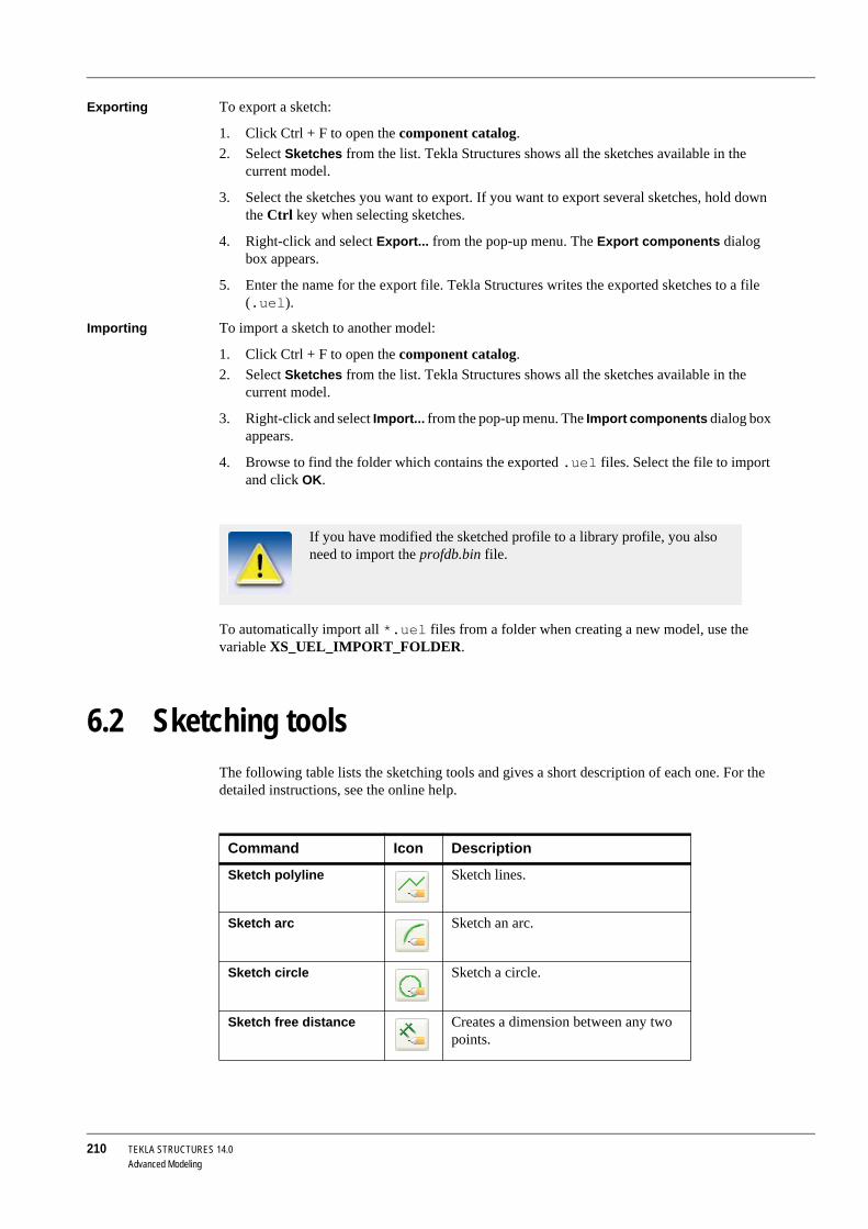
210 TEKLA STRUCTURES 14.0Advanced Modeling
Exporting To export a sketch:
1. Click Ctrl + F to open the component catalog.2. Select Sketches from the list. Tekla Structures shows all the sketches available in the
current model.
3. Select the sketches you want to export. If you want to export several sketches, hold down the Ctrl key when selecting sketches.
4. Right-click and select Export... from the pop-up menu. The Export components dialog box appears.
5. Enter the name for the export file. Tekla Structures writes the exported sketches to a file (.uel).
Importing To import a sketch to another model:
1. Click Ctrl + F to open the component catalog.2. Select Sketches from the list. Tekla Structures shows all the sketches available in the
current model.
3. Right-click and select Import... from the pop-up menu. The Import components dialog box appears.
4. Browse to find the folder which contains the exported .uel files. Select the file to import and click OK.
To automatically import all *.uel files from a folder when creating a new model, use the variable XS_UEL_IMPORT_FOLDER.
6.2 Sketching toolsThe following table lists the sketching tools and gives a short description of each one. For the detailed instructions, see the online help.
If you have modified the sketched profile to a library profile, you also need to import the profdb.bin file.
Command Icon Description
Sketch polyline Sketch lines.
Sketch arc Sketch an arc.
Sketch circle Sketch a circle.
Sketch free distance Creates a dimension between any two points.

TEKLA STRUCTURES 14.0 211Advanced Modeling
Sketch horizontal distance
Creates a horizontal dimension.
Sketch vertical distance Creates a vertical dimension.
Sketch radial dimension Creates a radial constraint for an arc or circle.
Sketch angle dimension Create an angle constraint between two lines. Angle is calculated counterclock-wise from the first selected line.
Parallel constraint Force a line to be parallel to another line.
Perpendicular constraint
Force a line to be perpendicular to another line.
Coincident constraint Force two lines to meet (extends or shortens one or both lines.) Useful when you need to close a shape.
Tekla Structures automatically creates coincident constraints:
• Where 2 lines meet• Between line segments when you
draw them with the Sketch polyline tool.
• Between the start of the first line segment and the end of the last line segment in a shape, if they are within a certain distance of each other.
Fixed constraint Locks the position and angle of a line, so that other constraints do not affect it.
Horizontal constraint Force a line in the sketch to be parallel to the local x axis. Use with other constraints to straighten the entire profile.
Tekla Structures automatically creates horizontal constraints for horizontal lines, and lines that are almost hori-zontal.
Vertical constraint Force a line in the sketch to be parallel to the local y axis. Use with other constraints to straighten the entire profile.
Tekla Structures automatically creates vertical constraints for vertical lines, and lines that are almost vertical.
Command Icon Description

212 TEKLA STRUCTURES 14.0Advanced Modeling
6.3 Parametric modelingTekla Structures models are parametric, which means that each model object, such as a beam or column, has parameters which define various properties, including its geometry, location and relationship to other parts. You can use these parameters to:
• Create dependencies, or relationships, between model objects, so the properties of one model object adjust if you change the related model object,
• Create variables that define the properties of the model object.
We call this technique parametric modeling.
This section describes the parametric modeling tools in Tekla Structures. It contains the following topics:
Creating dependencies (p. 212)
Creating variables (p. 213)
Creating dependenciesTekla Structures includes several tools that you can use to create dependencies, or relationships between model objects. For example, you might create a dependency that offsets a column a fixed distance from a plane on a wall, so that when you move the wall, the column follows.
Show or hide part posi-tioning planes
Allows you to move part positioning planes. When you use the profile in a model, the On plane and At depth part position options are based on these planes, not the outline of the profile.
Show or hide connec-tion positioning planes
Allows you to move connection posi-tioning planes.
Display variablesDis-play variables
View, add or change variables in para-metric model objects, including sketched cross sections.
Works the same way as Display vari-ables in the Custom component editor.
Display sketch browser Opens the sketch browser, which shows the elements in a sketched parametric cross section. Use to copy absolute values or references and use them as variables in parametric calculations.
Works in the same way as the Custom component browser.
Save sketch as Saves the cross section.
Close sketch Prompts you to save the sketch. Option to close the sketch without saving.
Command Icon Description

TEKLA STRUCTURES 14.0 213Advanced Modeling
Click Modeling > Add Distance to access the following parametric modeling tools:
Creating variablesUse variables to define the properties of a model object, such as a beam or column. Variables can define fixed properties, for example, the name of a column. Or they include formulas, so that Tekla Structures calculates the property value each time you use the model object.
The Modeling menu includes the following parametric modeling tools for defining and editing variables:
Command Icon Description
Add Distance > Fixed-Create distance
Binds a handle on a model object to up to 3 planes on other model objects, at a fixed distance. Illustrates the distance in the model view.
Works the same way as Create distance in the Custom component editor. For more information, see Defining vari-ables and Creating distance variables in the Detailing manual.
Add Distance > Refer-enceCreate reference distance
Creates a reference distance between model objects, which you can include in formulas in the Variables dialog box.
Works the same way as Create refer-ence distance in the Custom compo-nent editor. For more information, see Defining variables and Creating refer-ence distances in the Detailing manual.
Command Icon Description
Display Variables... View, add or change variables in model objects. You can use these variables to calculate the properties of related model objects. See also Using variables to define cross section properties (p. 201).
Works the same way as Display vari-ables in the Custom component editor.
Model Browser... Opens the model browser, which shows the elements in a model object. Use to copy absolute values or references and use them as variables in parametric calculations.
Works the same way as Custom component browser in the Custom component editor.

214 TEKLA STRUCTURES 14.0Advanced Modeling
6.4 Warping, cambering, and shortening partsThis section explains how to using various deforming tools to warp, camber, or shorten concrete parts.
It contains the following topics:
• Warping concrete parts (p. 214)• Using the Move Special tool to warp concrete slabs (p. 215)
• Cambering parts (p. 216)
• Shortening parts (p. 217)
Warping concrete partsThere are several ways to warp concrete parts:
Warping concrete beams using the Deforming optionsTo warp a concrete beam:
1. Double-click the beam to open the Beam properties dialog box and go to the Deforming tab.
2. In the Start field, enter the angle of the beam at its start point, relative to the part reference line.
3. In the End field, enter the angle of the beam at its end point, relative to the part reference line. For example, to warp the beam 45 degrees at the end point, enter 0 in the Start angle field and 45 in the End angle field.
4. Click Modify to warp the beam.
5. Click OK to close the dialog box.
Part type Warping method More information
Concrete beams Use the Deforming options in the part proper-ties dialog box
Warping concrete beams using the Deforming options (p. 214)
Concrete slabs created using the Slab gener-ation with points (62) component
• Use end offsets• Use the Move tool
Warping concrete slabs using end offsets (S62) (p. 215)
Using the Move Special tool to warp concrete slabs (p. 215)
Concrete slabs created using the Concrete slab component
Move slab chamfers Warping concrete slabs using chamfers (p. 216)

TEKLA STRUCTURES 14.0 215Advanced Modeling
Warping concrete slabs using end offsets (S62)To warp a concrete slab created using the Slab generation with points (62) component:
1. Click the Select objects in components on the Selecting toolbar 2. Double-click the slab to open the Beam properties dialog box and go to the Position tab.
3. In the End offsets section, enter the Start and End offsets of the slab, in the x, y or z direction, relative to the part reference line.
4. Click Modify to warp the slab.
5. Click OK to close the dialog box.
Using the Move Special tool to warp concrete slabsUse the Move Special command to warp slabs created using the Slab generation with points (S62)component, by picking a single point on the slab.
To warp a slab using the Move Special tool:
1. Click the following icons on the Selecting toolbar:
• Select objects in components
• Select points
2. Use a Crossing window to select the point you want to move.
3. Right-click and select Move Special > Linear from the pop-up menu.
4. In the Move - Linear dialog box, enter a value in the appropriate direction field. For example, enter 100 in the dZ field to lift that corner up 100 mm.
5. Click Move. Tekla Structures moves the point in the direction you selected, which warps the slabs.
For example, select the corner point of a slab component to warp that end of the slab

216 TEKLA STRUCTURES 14.0Advanced Modeling
6. Right-click and select Interrupt from the pop-up menu to finish.
7. To see the warping angle of a slab, double-click a slab to open the Beam properties dialog box. Go to the Deforming section of the Position tab.
• The Start field shows the warping angle at the start point of the part.• The End field shows the warping angle at the end point of the part.
Warping concrete slabs using chamfersTo warp concrete parts created using the Concrete slab component on the Concrete toolbar:
1. Double-click a chamfer on the part to open the Chamfer properties dialog box. Enter values in the following fields:
• dz1 to move the upper corner of the chamfer• dz2 to move the lower corner of the chamfer
2. Click Modify to warp the concrete slab.
3. Click OK to close the Chamfer properties dialog box.
Cambering partsUse the cambering option to pre-camber parts, that is to curve long heavy sections that will settle on site and become flat.
Tekla Structures cambers parts in the local z direction.
To camber a part:
1. Double-click the part to open the part properties dialog box.2. Go to the Deforming section of the Position tab.
3. In the Cambering field, enter the degree of camber.
4. Click Apply to modify the part.
5. Click OK to close the dialog box.
If the chamfers on a concrete slab are invisible, set the variable XS_DRAW_CHAMFERS_HANDLES=CHAMFERS.

TEKLA STRUCTURES 14.0 217Advanced Modeling
Limitations For the cambering to work correctly, you need to bind the objects to a cambered part, and the objects need to be part of an assembly or cast unit.
Parts assembled on-site cannot follow a cambered seam. Only embedded parts and custom parts follow the deformations of their parent part.
Shortening partsWhen drawings of the parts are created, Tekla Structures decreases the true length of the part by this value. This is useful when creating assembly drawings of bracing bars which should always be under tension.
To shorten a part:
1. Double-click the part to open the part properties dialog box.2. Go to the Deforming tab.
3. In the Shortening field, enter the degree of shortening.
4. Click Apply to modify the part.
5. Click OK to close the dialog box.
6.5 Modeling tipsThis section includes the following topics:
• General tips (p. 217)• Detailing (p. 218)
• Working with custom components (p. 218)
General tipsKeep the ’Move Special’ or ’Copy Special’ dialog boxes open if you are going to use them often, for example, when you creating the grids and levels in a new model.
To keep a dialog box open, start the command, then right-click and select Interrupt from the pop-up menu.
Each time you want to use the command:
1. Click in the appropriate dialog box to activate it, then click an object in the model.
You can also use the warping and cambering tools together to model parts.
To have a concrete part lengthened in cast unit drawings, type a negative value in the Shortening field.

218 TEKLA STRUCTURES 14.0Advanced Modeling
2. Enter the values you want to use, then click the Move or Copy button in the dialog box.
3. Tekla Structures moves or copies the object you selected.
DetailingThese detailing tips will help you to detail models more quickly and accurately, and avoid potential problems with templates, drawing, and exports.
Always model beams in the same direction.
Do not cut the end of a part to shorten it. This can cause shop errors, because cuts do not always affect part length when you export information to NC files. Move the part handles, or use Detailing > Fitting instead.
Do not use fitting to lengthen parts. It can cause problems with connections and details. Move the part handles instead.
Create a basic part view when you need to see a specific part clearly. This places the part in the center of the view. To further improve the view, use the Hide command to hide adjacent parts.
Working with custom componentsThese tips will help you to efficiently create, save, and share parametric and non-parametric custom components:
General Use library profiles when possible. So you do not have to copy user-defined profiles when you copy the component to other locations.
Use short, logical names. Use the description field to describe the component and explain what it does.
Store custom components together. It makes them easy to find and export. Consider creating a component model. Use this model to create and test custom components.
Provide essential information. If you distribute your component to other users, remember to list the profiles it works with.
Remember to copy user-defined profile cross sections with your custom component.
Creating non-parametric components
Use the simplest part you can. For example, if all you need is a rectangular shape, use a rectangular plate, not a contour plate. Rectangular plates only have 2 handles, so you only need to create a few bindings or magnetic planes to manipulate them. Contour plates require more because they have 4 chamfers and handles, when you set the variable XS_DRAW_CHAMFERS_HANDLESto CHAMFERS or HANDLES.
Leaving dialog boxes open uses up system memory and may slow down processes on your computer.

TEKLA STRUCTURES 14.0 219Advanced Modeling
Only model parts as accurately as you need. If the only part information required is a part mark on the GA drawing and a quantity on the materials list, create a simple bar or plate. If, later, you need to include it in a detailed view, simply re-model the part more accurately.
Creating intelligent (parametric) components
Plan to use magnetic planes to bind objects together. This makes intelligent components simpler, and easier to use, because it reduces the number of dimensions and parameters the user must enter. Model as many parts on the same plane as you can, and then use offsets to position them accurately.
Model embeds as custom parts and include them in components.
Create simple components for specific situations. It is faster and easier to model simple components. They are also much easier to use. Avoid creating a ’super’ component to use in every possible situation.
Rectangular plate
Contour plate
Not using magnetic planes:
Pick all 10 handles to bind the parts togetherUsing 3 magnetic planes:
Pick 3 points to bind the parts together (pick 1 point on each magnetic plane)

220 TEKLA STRUCTURES 14.0Advanced Modeling

TEKLA STRUCTURES 14.0 221Parametric Profiles
7 Parametric Profiles
These are the parametric profiles available in Tekla Structures:
HIh-s-t*b (symmetric)
HIh-s-t1*b1-t2*b2
PHIh1-h2-s-t*b (symmetric)
PHIh1-h2-s-t1*b1-t2*b2
BLLh*b*t
BLZh*b*t
BLUh*b*t

222 TEKLA STRUCTURES 14.0Parametric Profiles
PLh*bh=height
b=thickness
(smaller=b)
Dd
ELDd1*r1*d2*r2
PDd*t
EPDd1*r1*d2*r2*t
Ph*t
Ph*b*t
Ph1*b-h2*b*t
HKh-s-t*b-c (symmetric)
HKh-s-t1*b1-t2*b2-c

TEKLA STRUCTURES 14.0 223Parametric Profiles
HQh-s-t1*b1-t2*b2 (centered)
HQh-s-t1*b1-t2*b2-c
ZZh-t-e-b (symmetric)
ZZh-t-e1-b1-e2-b2
CCh-t-e-b (symmetric)
CCh-t-e1-b1-e2-b2
CWh-t-e-b-f-h1
CUh-t-h1-b-e (symmetric)
CUh-t-h1-b1-h2-b2/e
EBh-t-e-b-a (symmetric)
EBh-t-e1-b1-e2-b2-a
Reference points:1=right
2=left
3=top
BFh-s-b-h1

224 TEKLA STRUCTURES 14.0Parametric Profiles
SPDd*t
SPDd1-d2*t
ECh-t-e-b-a (symmetric)
ECh-t-e1-b1-e1-b1-a
EDh-t-b-e-h1-h2-f1-f2-a
EEh-t-e-b-f1-f3-h1-f2-a
EFh-t-e-b1-b2-f1-f2/h1-a
EZh-t-e-b-f1-f3-h1-f2-a

TEKLA STRUCTURES 14.0 225Parametric Profiles
EWh-t-e-b-b-f1-f2-h2-h1-a
RCDLs*h-d*t (symmetric)
RCDLs*h-d*t1*t2
RCXXs*h-b*t*h1-h2-ex
RCLs*h-b*t
RCDXs*h-b*h2*h1 (symmetric)
RCDXs*h-b*h4*h3*h2*h1
RCDXs*h-b*h4*h3*h2*h1-ex
RCXs*h-b*h2*h1

TEKLA STRUCTURES 14.0 226
Index
#4D tool ........................................................................ 186
aabout .......................................................................... 105assemblies ................................................................... 72
adding objects ....................................................... 75changing main part................................................ 79creating ................................................................. 75creating sub-assemblies of assembly ................... 76exploding............................................................... 76position numbers................................................. 173removing objects ................................................... 76working with .......................................................... 74
bbeep ........................................................................... 168bolt.............................................................................. 134bolt group shape......................................................... 109bolts........................................................... 105, 106, 110
creating ............................................................... 107location................................................................ 111
button ........................................................................... 30common buttons.................................................... 31radio button ........................................................... 30
ccanceling objects.......................................................... 41cast units ...................................................................... 72
changing main part................................................ 79top-in-form face ..................................................... 78working with .......................................................... 77
chamfer ...................................................................... 120
checkbox ......................................................................30modify filter checkboxes ........................................32
clash ...........................................................................134clash check.................................................................134clearance
bolt.......................................................................134clip planes...................................................................130closing
views .....................................................................60closing models..............................................................50color
grid ........................................................................54of model objects ......................................... 145, 166
color by class..............................................................166commands ....................................................................41
ending....................................................................42executing ...............................................................41repeating ...............................................................41using simultaneously .............................................42
compare......................................................................135concrete parts
creating................................................................103constraints
in sketched cross sections ..................................197construction circles .......................................................62construction lines..........................................................62construction planes.......................................................62coordinate.....................................................................44copying .............................................................. 138, 141creating.............................................................. 106, 130
assemblies ............................................................75bolts .....................................................................107cast units ...............................................................77concrete parts......................................................103grids.......................................................................52holes....................................................................107models...................................................................47objects ...................................................................41points .....................................................................61steel parts ............................................................102sub-assemblies of assembly parts ........................76views .....................................................................59welds ...................................................................112
creating zoom window ................................................127
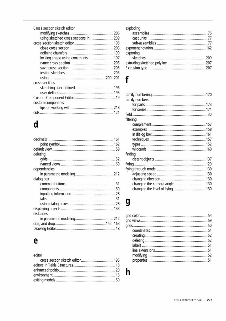
TEKLA STRUCTURES 14.0 227
Cross section sketch editormodifying sketches.............................................. 206using sketched cross sections in......................... 209
cross section sketch editor ......................................... 195close cross section.............................................. 205defining chamfers................................................ 199locking shape using constraints .......................... 197name cross section ............................................. 205save cross section............................................... 205testing sketches .................................................. 205using............................................................200, 201
cross sectionssketching user-defined ........................................ 196user-defined ........................................................ 195
Custom Component Editor ........................................... 19custom components
tips on working with............................................. 218cuts............................................................................. 121
ddecimals ..................................................................... 161
point symbol ........................................................ 162default view .................................................................. 59deleting
grids ...................................................................... 52named views ......................................................... 60
dependenciesin parametric modeling........................................ 212
dialog boxcommon buttons.................................................... 31components........................................................... 30inputting information.............................................. 28tabs ....................................................................... 31using dialog boxes ................................................ 28
displaying objects ....................................................... 143distances
in parametric modeling........................................ 212drag and drop .....................................................142, 163Drawing Editor.............................................................. 18
eeditor
cross section sketch editor.................................. 195editors in Tekla Structures............................................ 18enhanced tooltip ........................................................... 20environment.................................................................. 16exiting models .............................................................. 50
explodingassemblies ............................................................76cast units ...............................................................77sub-assemblies .....................................................77
exponent notation .......................................................162exporting
sketches ..............................................................209extruding sketched polyline ........................................207Extrusion type.............................................................207
ffamily numbering ........................................................170family numbers
for parts ...............................................................173for series..............................................................171
field ...............................................................................30filtering
complement .........................................................157examples .............................................................158in dialog box ........................................................161techniques ...........................................................157types....................................................................152wildcards .............................................................160
findingdistant objects .....................................................137
fitting ...........................................................................120flying through model ...................................................130
adjusting speed ...................................................130changing direction ...............................................130changing the camera angle .................................130changing the level of flying ..................................130
ggrid color .......................................................................54grid views......................................................................59grids..............................................................................50
coordinates............................................................51creating..................................................................52deleting..................................................................52labels .....................................................................51line extensions.......................................................51modifying ...............................................................52properties ..............................................................51
h

228 TEKLA STRUCTURES 14.0
handles .........................................................................82hiding
parts.....................................................................182hiding objects..............................................................143holes
creating................................................................107hover, see rollover highlight........................................164
iicons .............................................................................41
using ......................................................................23imperial units...............................................................162importing
sketches ..............................................................209inputting information .....................................................28inquire .........................................................................132interrupting
commands .............................................................42
kkeyboard
special keys ...........................................................32
llanguage.......................................................................16length ..........................................................................110library profiles ...............................................................67line ..............................................................................121list box...........................................................................30location of parts ............................................................82lotting ..........................................................................183
adding parts to a lot .............................................184creating................................................................183deleting a lot ........................................................185deleting parts from a lot .......................................185
m
magnifier .....................................................................127material .........................................................................69measure ......................................................................132menu tooltip ..................................................................21menus
menu bar................................................................20pop-up....................................................................41pull-down ........................................................ 20, 41
model browserin parametric modeling ........................................213
Model Editor..................................................................18basic toolbars.........................................................24screen layout .........................................................19select switches.......................................................38
modelingbasics.....................................................................43introduction ............................................................15parametric modeling ............................................212tips .......................................................................217
modeling tipsdetailing ...............................................................218keep move or copy dialog boxes open ................217working with custom components........................218
modify filter checkboxes................................................32modifying
assemblies.............................................................74cast units................................................................77grids .......................................................................52objects ...................................................................42polygonal part ......................................................123sketched cross sections.......................................206views......................................................................59
mouse settings............................................................163moving .......................................................128, 140, 141
toolbars ..................................................................23moving the model in the view window.........................128multiple selection list .....................................................30multiuser vs single-user ................................................18
nnested assemblies ........................................................72

TEKLA STRUCTURES 14.0 229
numbering .................................................................. 168and pop-marking ................................................. 175applying............................................................... 175assigning control numbers .................................. 176example............................................................... 174family numbering................................................. 170history log............................................................ 175interrupting .......................................................... 175locking and unlocking control numbers ............... 176log file.................................................................. 175modified parts...................................................... 170new parts............................................................. 170parts ...................................................................... 79settings................................................................ 168what affects ........................................................... 80
oobject groups.............................................................. 146
rules .................................................................... 148object representation.................................................. 143objects ........................................................................ 143
cancel.................................................................... 41colors................................................................... 145creating ................................................................. 41finding.................................................................. 137groups ................................................................. 146modifying............................................................... 42visibility
transparency ................................................ 146opening
models................................................................... 45views ..................................................................... 60
options........................................................................ 166
ppan ............................................................................. 163parametric modeling................................................... 212
creating dependencies ........................................ 212creating variables ................................................ 213model browser..................................................... 213
parametric profiles........................................................ 67part ............................................................................. 122part labels................................................................... 136
parts..............................................................................65cambering............................................................216concrete parts......................................................103hiding...................................................................182labels ...................................................................136location ..................................................................82numbering .............................................................79position ..................................................................82properties ..............................................................66shortening............................................................217steel parts ............................................................102user-defined attributes...........................................71warping concrete parts ........................................214warping, cambering, and shortening ...................214
phases ........................................................................164adding properties.................................................165example...............................................................164working ................................................................164
picking points................................................................33snap switches........................................................33Xsnap ....................................................................35
planespositioning ...........................................................200
pointer................................................................ 163, 164pointer settings ...........................................................163
drag and dropSmart Select.................................................163
rollover highlight ..................................................164points ............................................................................61
coordinates............................................................61creating..................................................................61phase.....................................................................61picking ...................................................................33specifying ..............................................................33
polygon .......................................................................122polygon shape ............................................................123pop-up menu ................................................................41position of parts ............................................................82profile cross sections
user-defined ........................................................195profiles
library profiles ........................................................67parametric profiles .................................................67part profile .............................................................67sketching user-defined ........................................196user-defined profiles ..............................................67using sketched cross sections in models ............209
project properties..........................................................47project status visualization..........................................186properties....................................................................115pull-down menu ..................................................... 20, 41

230 TEKLA STRUCTURES 14.0
qquerying objects..........................................................132
rradio button...................................................................30reference.......................................................................82reference distance
in parametric modeling ........................................212reference points
in snapping ..........................................................179rendered view ...............................................................57repeating commands ....................................................41rollover highlight..........................................................164rotating model .............................................................129
automatically........................................................129in rendered view ..................................................129in wire frame view................................................129
rotating view................................................................130rules
object groups .......................................................148
ssaving models...............................................................50screen components ......................................................20screen layout
in Model Editor.......................................................19screenshot ..................................................................191
function keys........................................................191print......................................................................191
select filterconverting ............................................................155defining ................................................................156dialog box ............................................................153standard...............................................................154using ....................................................................153
select switchesin Model Editor.......................................................38
selecting objectscontrolling the selection .........................................38how to select..........................................................36in model .................................................................36select switches, in Model Editor ............................38
selection......................................................................153selection filter..............................................................153
sequencer ...................................................................185adding parts .........................................................186creating new sequence........................................186how it works .........................................................185using ....................................................................185
settings........................................................................161show assembly ...........................................................183showing
objects .................................................................143single-user vs multiuser ................................................18sketched cross section
importing and exporting .......................................209sketching
tools .....................................................................210Smart Select ...............................................................163snap grid .....................................................................167snap settings.......................................................... 33, 35snap switches ...............................................................33
overriding temporarily ............................................35snapping .....................................................................177
to numeric coordinates ........................................177to orthogonal directions .......................................178using temporary reference points ........................179using tracking.......................................................179
snapshot .....................................................................191function ................................................................191print......................................................................191
special keys ..................................................................32specifying points ...........................................................33start flying....................................................................130status bar ......................................................................22steel parts
creating ................................................................102stop flying....................................................................130sub-assemblies .............................................................72
creating ..................................................................76exploding ...............................................................77
surface treatmentabout......................................................................89adding tiled surface treatment to parts ..................93adding to chamfered parts ...................................100adding to parts .......................................................89adding to parts with cuts and recesses..................98defining properties .................................................91defining tile patterns...............................................93editing existing .....................................................100in reports and templates ......................................101user-defined.........................................................100
Symbol Editor................................................................18
t

TEKLA STRUCTURES 14.0 231
Template Editor ............................................................ 18temporary reference points ........................................ 179testing
sketched cross sections ...................................... 205thickness of a sketched polyline................................. 207tips
modeling.............................................................. 217tolerate ....................................................................... 164toolbars......................................................................... 23
in Model Editor ...................................................... 24moving................................................................... 23
toolsexact lines ........................................................... 181hide lines ............................................................. 181show.................................................................... 182
tooltip............................................................................ 20top-in-form face ............................................................ 78tracking....................................................................... 179transparency
objects................................................................. 146transparent commands................................................. 42
uunits............................................................................ 162units and decimals...................................................... 161
imperial................................................................ 162no effect .............................................................. 162
user interfacein Model Editor ...................................................... 19
user-defined part attributes .......................................... 71user-defined profiles..................................................... 67
using in models ................................................... 209
vview ........................................................................44, 45view plane .................................................................... 56
basic view plane.................................................... 56
views.................................................................... 55, 143angle......................................................................58closing ...................................................................60creating..................................................................59default view ...........................................................59deleting named views............................................60grid views ..............................................................59modifying ...............................................................59naming...................................................................56opening..................................................................60projection...............................................................58properties ..............................................................56rendered ................................................................57representation .......................................................57types......................................................................57wire frame..............................................................57
visibility .......................................................................143objects .................................................................146
visualization tool .........................................................186
wwarping
concrete parts......................................................214weld preparation .........................................................119welds ..........................................................................115
creating................................................................112position ................................................................117symbols ...............................................................113types....................................................................116
wheel mouse ..............................................................126wildcards.....................................................................160windows, using .............................................................22wire frame.....................................................................57work ..............................................................................45work area......................................................................49work plane ....................................................................49
xXmouse ......................................................................163Xsnap .................................................................. 35, 164
z

232 TEKLA STRUCTURES 14.0
zooming ......................................................................1273-button mouse....................................................126centered zooms ...................................................127commands ...........................................................125keystrokes ...........................................................127magnifier..............................................................127settings ................................................................127wheel ...................................................................126zoom in ................................................................126zoom out..............................................................126zoom ratio............................................................127