TEDS- - Durham Instruments Operating... · imports the transducer characteristics ... by right...
36
A1813-1.1 en TEDS- memory module in transducer - Content and editing the memory module Operating Manual
-
Upload
truongtruc -
Category
Documents
-
view
215 -
download
1
Transcript of TEDS- - Durham Instruments Operating... · imports the transducer characteristics ... by right...

A1813-1.1 en
TEDS-memory module in
transducer -
Content and editing
the memory module
Operating Manual


3TEDS
A1813-1.1 en HBM
Contents Page
Safety information 4 . . . . . . . . . . . . . . . . . . . . . . . . . . . . . . . . . . . . . . . . . . . . . .
1 Field of application 6 . . . . . . . . . . . . . . . . . . . . . . . . . . . . . . . . . . . . . . . . . .
2 The contents of the TEDS memory 7 . . . . . . . . . . . . . . . . . . . . . . . . . . .
3 Writing to or altering the memory contents 9 . . . . . . . . . . . . . . . . . . . 3.1 General 9 . . . . . . . . . . . . . . . . . . . . . . . . . . . . . . . . . . . . . . . . . . . . . . . . . 3.2 The TEDS Editor reference options 9 . . . . . . . . . . . . . . . . . . . . . . . . . 3.3 Using the TEDS-Editor 10 . . . . . . . . . . . . . . . . . . . . . . . . . . . . . . . . . . . .
3.3.1 Editing TEDS in the HBM-view 10 . . . . . . . . . . . . . . . . . . . . . . . . 3.3.2 Editing TEDS in the Template view 12 . . . . . . . . . . . . . . . . . . . . .
4 The main templates 12 . . . . . . . . . . . . . . . . . . . . . . . . . . . . . . . . . . . . . . . . . 4.1 Basic TEDS 13 . . . . . . . . . . . . . . . . . . . . . . . . . . . . . . . . . . . . . . . . . . . . . 4.2 Templates for definition of transducer type 13 . . . . . . . . . . . . . . . . . . . 4.3 Optional templates 20 . . . . . . . . . . . . . . . . . . . . . . . . . . . . . . . . . . . . . . . . 4.4 Other templates 23 . . . . . . . . . . . . . . . . . . . . . . . . . . . . . . . . . . . . . . . . . .
5 Examples for operating with TEDS 24 . . . . . . . . . . . . . . . . . . . . . . . . . . . 5.1 Example 1 24 . . . . . . . . . . . . . . . . . . . . . . . . . . . . . . . . . . . . . . . . . . . . . . . 5.2 Example 2 26 . . . . . . . . . . . . . . . . . . . . . . . . . . . . . . . . . . . . . . . . . . . . . . .
6 Specifications 33 . . . . . . . . . . . . . . . . . . . . . . . . . . . . . . . . . . . . . . . . . . . . . .
Information on TEDS is provided in every operating manual of HBMtransducers supporting TEDS.
For more information on the different mounting possibilities, pleaserefer to the mounting instructions “TEDS memory module in connector”and “TEDS memory module in the transducer cable” at our Web site
www.hbm.com/TEDS

4 TEDS
A1813-1.1 enHBM
Safety information
Appropriate useThe TEDS module is to be used only as an accessory for transducers inconjunction with suitable measuring amplifiers. Use for any purpose otherthan the above shall be deemed to be inappropriate.In the interests of safety, the module must only be fitted and operated asspecified in the mounting instructions. It is also necessary to observe theregulations for operating the transducer and the amplifier respectively. It isalso essential to observe the appropriate legal and safety regulations for theapplication concerned during use.
General dangers of failing to follow the safety instructionsThe TEDS module is a state of the art unit and as such is failsafe. The modulemay give rise to dangers if it is inappropriately installed and operated byuntrained personnel.Any person instructed to carry out the installation, commissioning,maintenance or repair of the transducer, TEDS module and amplifier musthave read and understood the Operating Manual and in particular thetechnical safety instructions.
Remaining dangersThe scope of supply and list of components provided with the TEDS modulecover only part of the scope of measurement technique. In addition,equipment planners, installers and operators should plan, implement andrespond to the safety engineering considerations of measurement technologyin such a way as to minimize remaining dangers. Prevailing regulations mustbe complied with at all times. There must be reference to the remainingdangers connected with measurement technology.Any risk of remaining dangers when working with the TEDS module is pointedout in this introduction by means of the following symbols:
Symbol: WARNINGMeaning: Dangerous situationWarns of a potentially dangerous situation in which failure to comply withsafety requirements can lead to death or serious physical injury.

5TEDS
A1813-1.1 en HBM
Symbol: CAUTION Meaning: Potentially dangerous situationWarns of a potentially dangerous situation in which failure to comply withsafety requirements could lead to damage to property and slight or moderatephysical injury.
Symbol: NOTEMeans that important information about the product or its handling is beinggiven.
Conversions and ModificationsThe module must not be modified from the design or safety engineering pointof view except with our express agreement. Any modification shall exclude allliability on our part for any damage resulting thereof.In particular, any repair or soldering work on motherboards is prohibited.
Qualified personnelThis module is only to be installed and used by qualified personnel strictly inaccordance with the specifications and within the safety rules and regulationswhich follow. It is also essential to observe the appropriate legal and safetyregulations for the application concerned during use. The same applies to theuse of accessories.Qualified personnel means persons entrusted with the installation, assembly,commissioning and operation of the product, who possess the appropriatequalifications for their function.
Symbol:Meaning: CE markThe CE mark enables the manufacturer to guarantee that the productcomplies with the requirements of the relevant EC directives (see Declarationof Conformity at the end of this Operating Manual).

6 TEDS
A1813-1.1 enHBM
1 Field of application
TEDS stands for ”Transducer Electronic Data Sheet”.Stored in this module’s memory is an electronic data sheet which enables themeasuring amplifier to be set up automatically. A suitably equipped amplifierimports the transducer characteristics (electronic data sheet), translates theminto its own settings and measurement can then start.A special circuit (patent applied for) makes it possible to use the existing cableleads for transferring the TEDS data. This means that the same cables can beused as for transducers that do not have TEDS.This is done by switching between a measurement mode (the line transfersthe analog measurement signal) and a data mode (the line transfers thedigital TEDS data).
Transducer with TEDSmodule
TEDS-enabled measuringamplifier
Data modeMeasurementmode
Fig.1.1: The TEDS concept

7TEDS
A1813-1.1 en HBM
2 The contents of the TEDS memory
The information in the TEDS memory is organized in table form.Only the entered values are stored in the TEDS memory itself.The amplifier firmware assigns the interpretation of the respective numericalvalues. This places a very low demand on the TEDS memory.
What is stored on the module?The memory contents are divided into four areas
• Area 1
An internationally unique identification number (cannot be changed).
• Area 2
The base area (basic TEDS) to the configuration defined in standardIEEE 1451.4. This contains the transducer type, manufacturer and serialnumber of the transducer (writing to or amending this area requires userrights for the ID level).
• Area 3
This area contains characteristic transducer data that can be defined by themanufacturer, by calibration or by the user. They are organized intoso-called templates which store defined groups of data in a summarizedform.
At least 1 template must be present for transducer description; thiscontains the specification
- the transducer type,- the measured quantity,- the electrical output signal,- the required excitation,- the characteristic curve, etc.
The standard specifies templates for the most important types oftransducers. HBM has developed a dedicated template for other HBMtransducer types in the form laid down in the standard.
Optionally, additional templates can be used – partly defined by the standard,partly by HBM – to store further information in the transducer, e.g.compensating polynomial expressions from a calibration.
As a guide to the terms with which the templates work, Chapter 4 contains the main templates with explanations.

8 TEDS
A1813-1.1 enHBM
Some of the data in the templates can be stored by the user themselves, e.g.
- a measuring point identification number,- filter settings,- a zero value, a tare value,- a short comment.
Detailed descriptions for individual templates can be found in Chapter 4.
User rights hierarchyVarious user rights are needed in order to amend the different entries in thetemplates, and these rights may differ from one entry to the next within atemplate.
• Standard rights (USR level)
This level concerns rights that the operator of the transducer needs in orderto change entries which depend on the conditions of use.
• Calibration rights (CAL level)
This level concerns rights which are needed by a calibration laboratory, forinstance, if the sensitivity in the TEDS memory needs to be changed.
• Administrator rights (ID level)
Administrator rights in relation to TEDS are intended for the sensormanufacturer. In the case of a self-built sensor or subsequent upgradingwith TEDS, HBM customers can of course also make use of these rights.

9TEDS
A1813-1.1 en HBM
3 Writing to or altering the memory contents
3.1 General
If TEDS is referenced at HBM as a complete solution on new HBMtransducers or as an expansion of existing transducers, data is already writtento the TEDS memory so that the TEDS can be used immediately. This appliesto both transducers with TEDS memory integrated in the transducer housingand those fitted with a TEDS module in the transducer connector or cable.The user then has to enter variations and amendments if necessary.
If TEDS modules are referenced for self fitting, the user has to write thetransducer data to the TEDS memory.
NOTEIf additional, optional templates are created and some aremanufacturer-specific, it is recommended for compatibility reasonsalways to arrange the manufacturer-specific templates in theTEDS memory after all templates which meet the IEEE 1451.4standard. Otherwise there is a risk that the last IEEE templatescannot be interpreted.
3.2 The TEDS Editor reference options
HBM provides you with the TEDS Editor for storing your dataThis is included in the software for the MGCplus -Setup- Assistant fromversion 3.1 and higher (on the system -CD supplied with every MGC systemand in its constantly updated version as a download from www.hbm.com->Unterstützung / Support -> Downloads->Software -> MGCplus-Assistent).Similarly the TEDS Editor is included in the HBM catman measurementsoftware from version 5.0 and higher (older versions of catman can also becombined with an updated version of the MGCplus Setup Assistant, so thatthe TEDS-Editor is available).

10 TEDS
A1813-1.1 enHBM
3.3 Using the TEDS-Editor
Calling up the TEDS Editor presupposes that the transducer to be edited isrecognized as the TEDS transducer by the higher level software. Call up theEditor by clicking on ”Edit TEDS” in the context menu, which can be openedby right clicking on the transducer.The TEDS Editor offers two operating modes: The HBM view and theTemplate view. The TEDS Editor supports the user rights hierarchy, consistingof the permissions IDENT (manufacturer), CAL (calibrator), USR (user) and alevel with exclusively read rights (see chapters 2 and 4 regarding the rights ofthe various levels).USR is set by default for the operator. When the higher level software isimplemented via the access to the Assistant which has user rightsadministration (e.g. MGCplus Assistant), the user rights can be modified. Thisis in particular necessary when the operator has to implement the moduleprogramming themselves after installing the TEDS module.
NOTEIf the user rights in levels CAL or IDENT are used, there is adanger of unintentional overwriting of the central transducer data.
3.3.1 Editing TEDS in the HBM-view
The HBM view is orientated around the definitions and transducer parametersthat are normally used with HBM measurement technology. For example, theinput of a transducer characteristic curve can be implemented in two ways:
• Value pair based on nominal value (e.g. the nominal force for a forcetransducer) and sensitivity (output signal at nominal value, minus theoutput signal in relaxed state).
• Input of two points that are each defined by a physical value and therespective output signal.
The setting options essential for working with HBM transducers are clearlylaid out in the form of ”tabs” that simply have to be filled in. Editing options arerestricted when working with user rights in the hierarchies USR (operator) orCAL (calibrator). A separate field displays the entries that are stored in thebasic memory (Basic TEDS). Changing entries in the basic memory (apartfrom the serial number) requires that a completely new TEDS content must begenerated. The following tabs are available:

11TEDS
A1813-1.1 en HBM
• General:Transducer circuit with bridge type and resistance, calibration data, channelname (channel name is HBM specific)
• Characteristic curve:Transducer characteristic curve, defined either via (a) zero values, nominalvalue and sensitivity or via (b) two points
• Power supply:Data regarding supply voltage or electrical supply
• Signal processing (HBM specific):Data regarding high or low pass filtering, tare or zero value. This data isoptional, if no values are entered in TEDS, the respective settings of theamplifier are retained when reading in the TEDS data.
• Units conversion (HBM specific):Conversion from the physical units specified in the Standard IEEE 1541.4to any units required
To create a completely new TEDS, the transducer type must first bedetermined; this can be done with the simple function ”TEDS content new(HBM transducer)” where the right type can simply be selected from a list ofHBM transducers. Generalized samples are also available for specialtransducers.

12 TEDS
A1813-1.1 enHBM
3.3.2 Editing TEDS in the Template view
The Template view uses the definitions in the Standard IEEE 1451.4 anddisplays the entered values in the same way that they are stored in the TEDSmemory. The main templates for use with HBM transducers are listed in thefollowing chapter. This includes, in addition to the templates defined in theStandard IEEE 1451.4, those that have been supplemented in definition byHBM based on the standard.The Template view displays the structure of the TEDS memory on the leftscreen side in the form of a tree structure. If you click in this diagram on theicon for the basic memory (Basic TEDS) or one of the subordinate icons forindividual templates, these are shown on the right screen side in table form.The table entries can then be easily edited. Editing options are restrictedwhen working with user rights in the hierarchies USR (operator) or CAL(calibrator).When creating completely new TEDS contents, the individual templates mustfirst be generated via the command sequence ”Edit” – ”New” – ”Newtemplate”. The minimum requirement is at least one template created thatdescribes the respective transducer type (e.g. ”Bridge Sensor” for SG-basedtransducer). Supplementary optional templates (e.g. ”HBM Channel Name”,”Calibration Curve”) can be added at any time (please note the information onPage 10).
4 The main templates
The following detailed information about the content of individual TEDStemplates is to facilitate writing of TEDS contents in the Template view (seeChapter 3.3.2 ). This procedure is however generally not necessary. Mostentries can be made more easily via the self-explanatory input fields in theHBM view (see Chapter 3.3.1 ).All the terms and expression in a template are in English, since they aredefined in this language only in the IEEE 1451.4 standard.Occasionally the number of bits specified by the standard is so low that thenumeric values entered cannot be adopted exactly.Additions for units of measurement such as m (for milli-...), k (for kilo-...), ustanding for µ (micro-...) etc. are in the value column, not the unit column.

13TEDS
A1813-1.1 en HBM
4.1 Basic TEDS
Basic TEDS according to IEEE 1451.4Parameters Value 1) Unit Change
requiresrights to
level:
Explanation
Manufacturer HBM - ID Initially stored only in the form of a num-ber (e.g. No. 31 for HBM). Numbers areassigned to manufacturers’ names in a
table drawn up by the IEEE as a supple-ment to the standard. This table must bestored in the software which TEDS im-ports. This entry can only be input or
amended if no other templates have beencreated.
Model: WA - ID Initially stored only in the form of a num-ber. Numbers are assigned to type namesin a table which can be drawn up by the
respective manufacturer (HBM does this).This table must be stored in the softwareor amplifier from which TEDS imports ifyou wish the type name to be shown in
plain text.Version letter - ID Possible values: a letter from ”A” to ”Z”Version number 7 - ID Possible values: a number from 0 to 63.
The serial number positions that precedethe last 7 places for HBM transducers arestored here. Leading zeroes are not dis-
played (HBM serial numbers are nonethe-less unique).
Serial number 2610137 - ID Possible values: a number from 0 to16777215. The last 7 serial number posi-
tions for HBM transducers are storedhere. Leading zeroes are not displayed.
1) Typical entries for a WA displacement transducer from HBM
4.2 Templates for definition of transducer type
IEEE bridge sensor templateThe physical measured quantity and physical unit are defined when themanufacturer (or user) creates the template.The available units are specified for the respective measurement parametersin the IEEE Standard. These are, for example, for the measurement of forcethe units N, kp, lb; for mass, the units kg and g; for pressure, the units PSIand Pa.

14 TEDS
A1813-1.1 enHBM
At the time of creating the template it is also necessary to choose between theoptions ”Full Precision”, ”mV/V” and ”uV/V” for the accuracy of thecharacteristic transducer curve mapped in TEDS.HBM always opts for ”Full Precision” here, in order to be able to use full digitalresolution. This choice is also recommended to operators who program theTEDS memory themselves.
Parameters Value 1) Unit Changere-
quiresrights
to level:
Explanation
Transducer ElectricalSignal Type
Bridgesensor
ID
Minimum Force/Weight 0.000 N CAL The physical measured quantity andunit are defined when the template
Maximum Force/Weight 2000k N CALunit are defined when the templateis created, after which they cannot
be changed.Minimum ElectricalValue
0.000 V/V CAL The difference between these val-ues is the sensitivity according to
Maximum ElectricalValue
1,999m V/V CALues is the sensitivity according tothe HBM test certificate and from
calibration.Mapping Method Linear This entry cannot be changed.Bridge type Full ID The bridge type. The following val-
ues are available for selection:”Quarter” for quarter bridge, ”Half”for half bridge, ”Full” for full bridge.
Some HBM transducers can be con-nected as half bridges or full bridgesaccording to choice. For SG-basedtransducers from HBM the bridge
type is always full bridge.Impedance of eachbridge element
345.0 ohms ID Input resistance according to theHBM data sheet.
Response Time 1.0000000u sec ID Of no significance for HBM trans-ducers.
Excitation Level(Nominal)
5.0 V ID Nominal excitation voltage accord-ing to the HBM data sheet.
Parameters Value 1) Unit Changere-
quiresrights
to level:
Explanation
Excitation Level(Minimum)
0.5 V ID Lower limit for the operating rangeof the excitation voltage according
to the HBM data sheet.Excitation Level(Maximum)
12.0 V ID Upper limit for the operating rangeof the excitation voltage according
to the HBM data sheet.

15TEDS
A1813-1.1 en HBM
Parameters Value 1) Unit Changere-
quiresrights
to level:
Explanation
Calibration Date 4-Dec-2003 CAL Date of the last calibration or cre-ation of the test certificate (if no cal-ibration carried out), or of the stor-age of the TEDS data (if only nomi-nal values from the data sheet were
used). Format: day-month-year.
Abbreviations for the months: Jan,Feb, Mar, Apr, May, Jun, Jul, Aug,
Sep, Oct, Nov, Dec.Calibration Initials HBM CAL Initials of the calibrator or calibration
laboratory concerned.Calibration Period(Days)
730 days CAL Time before recalibration, calculatedfrom the date specified under Cal-
ibration Date.Measurement locationID
0 USR Identification number for the mea-suring point. Can be assigned ac-cording to the application. Possiblevalues: a number from 0 to 2047. Ifthat is not enough, the HBM Chan-nel Comment template can also be
used for this purpose.1) Typical values for a type U3 force transducer from HBM

16 TEDS
A1813-1.1 enHBM
HBM template: Inductive Displacement TransducerThe physical unit is defined when the transducer manufacturer (or user)creates the template. At the time of creating the template it is also necessaryto choose between the options ”Full Precision”, ”mV/V” and ”µV/V” for theaccuracy of the characteristic transducer curve mapped in TEDS. HBMalways opts for ”Full Precision” here, in order to be able to use full digitalresolution. This choice is also recommended to operators who program theTEDS memory themselves.
Parameters Value 1) Unit Change re-
quiresrights
tolevel:
Explanation
Transducer ElectricalSignal Type
Bridgesensor
ID
Minimum Distance 0.000E+000 mm CAL The difference between these val-ues is the nominal displacement ac
Maximum Distance 5.000E+001 mm CALues is the nominal displacement ac-
cording to the HBM data sheet.Minimum ElectricalValue
0.000 V/V CAL The difference between these val-ues is the sensitivity according to
Maximum ElectricalValue
80.000m V/V CALues is the sensitivity according to
the HBM data sheet, the HBM testcertificate or from calibration.
Mapping Method Linear This entry cannot be changed.Bridge type Full The bridge type.
The following values are availablefor selection: ”Quarter” for quarterbridge, ”Half” for half bridge, ”Full”
for full bridge. Some HBM transduc-ers can be connected as half
bridges or full bridges according tochoice.
Transducer ResponseTime
1.0000000u sec-onds
ID Of no significance for HBM trans-ducers.
Excitation Level (Nomi-nal)
2.5 Volts ID Nominal excitation voltage accord-ing to the HBM data sheet.
Excitation Level (Maxi-mum)
10.0 Volts ID Upper limit for the operating rangeof the excitation voltage according
to the HBM data sheet.Excitation Voltage Type AC (rms) ID This entry cannot be changed.Excitation Frequency(Nominal)
4801 Hz ID Nominal value for the carrier fre-quency of the excitation voltage ac-
cording to the HBM data sheet.Excitation Frequency(Minimum)
4421 Hz ID Lower limit of the operating rangefor the carrier frequency of the ex-citation voltage according to the
HBM data sheet.Excitation Frequency(Maximum)
5181 Hz ID Upper limit of the operating rangefor the carrier frequency of the ex-citation voltage according to the
HBM data sheet.1) Typical values for a type WA displacement transducer, measuring range 50 mm, from HBM

17TEDS
A1813-1.1 en HBM
Parameters Value 1) Unit Change re-
quiresrights
tolevel:
Explanation
Input Impedance @nominal frequency
102 Ohms ID Input resistance according to theHBM data sheet.
Calibration Date 10-Dec-2003 CAL Date of the last calibration or cre-ation of the test certificate (if no cal-ibration carried out), or date of stor-ing the TEDS data (if only nominalvalues from the data sheet were
used).
Format: day-month-year.
Abbreviations for the months: Jan,Feb, Mar, Apr, May, Jun, Jul, Aug,
Sep, Oct, Nov, Dec.Calibration Initials HBM CAL Initials of the calibrator or calibration
laboratory concerned.Calibration Period(Days)
730 days CAL Time before recalibration
Measurement locationID
0 USR Identification number for the mea-suring point. Can be assigned ac-cording to the application. Possiblevalues: a number from 0 to 2047. Ifthat is not enough, the HBM Chan-nel Comment template can also be
used for this purpose.1) Typical values for a type WA displacement transducer, measuring range 50 mm, from HBM

18 TEDS
A1813-1.1 enHBM
HBM template:Freqsensor:Physical and electrical units are specified before a template is created by themanufacturer. In addition, a selection must be made during creation betweenthe variants ”Frequency” or ”Counter”.It must also be specified which resolution should be used: 24 Bit, 16 Bit or 8Bit.
Parameters Value Unit Change re-
quiresrights
tolevel:
Explanation
Transducer electrical SignalType
Pulse Sensor ID
Minimum Velocity 0.000E+000 rpm CAL Physical Measurement pa-rameters and units are de-
Maximum Velocity 1.000E+004 rpm CALrameters and units are defined when the template is
createdPulse Measurement Type Frequency CAL Measuring mode frequency
measurement or pulsecounting
Minimum Electrical Value 0.0 Hz CAL The difference betweenthese values is the sensi-
tivity according to the HBMMaximum Electrical Value 60000.0 Hz CAL
tivity according to the HBMdata sheet, the HBM testcertificate or from calibra-
tion.Mapping Method Linear Cannot be changedDiscrete Signal Type Bipolar Input mode:
Contact to ground,
Contact to Power,
Discrete Signal Amplitude 4 Volts Active Low,
Active High,
BipolarDiscrete Signal Configuration single Evaluation F2 signal;
Single
Double 90 degree
Double phase plus zeroindex
Transducer Response Time 1.0000000u seconds Of no significance for HBMtransducers.

19TEDS
A1813-1.1 en HBM
Parameters Value unit Change re-
quiresrights
tolevel:
Explanation
Excitation level, nominal 0.1 Volts ID Nominal excitation voltageExcitation level, min. 0.1 Volts ID Lower limit for the operat-
ing range of the excitationvoltage according to the
HBM data sheet.Excitation level, max. 0.1 Volts ID Upper limit for the operat-
ing range of the excitationvoltage according to the
HBM data sheet.Excitation Voltage Type Bipolar DC ID This entry cannot be
changed.Excitation Current Draw 300,000u Ampere ID Excitation current con-
sumptionCalibration Date 15-Jun-2005 CAL Date of last calibrationCalibration Initials HBM CAL Initials of calibratorCalibration Period (Days) 365 days CAL Time before recalibrationMeasurement location ID 0 USR Identification number for
the measuring point. Pos-sible values: 0 to 2047

20 TEDS
A1813-1.1 enHBM
4.3 Optional templates
In addition to the essential templates required for describing the transducer,the Standard IEEE 1451.4 also provides for optional templates which allowthe opportunity to store further information about the transducer in the TEDSmemory. Further optional templates can be provided manufacturer-specific byHBM.HBM template: Signal ConditioningWhen the transducer manufacturer (or user) creates the template, a definitionis entered about the possible settings for which entries may be stored in theTEDS memory. As an example it is possible to create the template in such away that the only value which may be stored in TEDS is the cut-off frequencyfor the lowpass filter.This has the advantage for users who prefer to carry out a manual zerobalance that the Zero Compensation Value parameter will not be overwrittennext time the TEDS memory is imported.
Parameters Value(example)
unit Changere-
quiresrights
to level:
Explanation
Lowpass Filter Character-istics
Bessel USR Possible entries: Bessel or Butter-worth
Lowpass Filter Frequency 1.000 Hz USR If the TEDS memory contains valueswhich the measuring amplifier can-not adopt - because filter settings
are only possible in certain fre-quency steps - the next closest step
is set up.High-pass FilterFrequency
100.000 Hz USR If the TEDS memory contains valueswhich the measuring amplifier can-not adopt - because filter settings
are only possible in certain fre-quency steps - the next closest step
is set up.Zero Compensation Value 480.000m Phys.
unitUSR Zero offset
Tare Value 0.000 Phys.unit
USR Tare

21TEDS
A1813-1.1 en HBM
HBM template: User Channel Comment
Parameters Value(example)
Change requiresrights to level:
Explanation
User Channel Comment my transducer USR Comment of up to 45characters in 7-bit ASCII
IEEE templateCalibration Curve:
Parameters Value(example)
Unit Change re-
quiresrights
tolevel:
Explanation
Domain parameter of the Cal-ibration Curve
Physical CAL
Calibration curve segments 1 Elements CAL1. Starting domain value ofsegment (% of full span)
0 % CAL
Calibration curve polynomial 3 Elements CAL1. Power of domain value 1) 1.0 CAL y = a1x1 + a2x2 + a3x3
Power for the first poly-nomial element (1 in the
example)1. Polynomial coefficient 9.999E+001 CAL y = a0 x0 + a1 x1
2. Power of domain value 2.0 CAL2. Polynomial coefficient 2.000E-002 CAL3. Power of domain value 3.0 CAL3. Polynomial coefficient -5.000E-003 CAL
NOTERange is always from 0% to 100%; i.e. when the lowest value, e.g.is -200 N, this corresponds to 0% (and not -100%).
1) a0 x0 = measured value; a0 = Polynomial coefficient

22 TEDS
A1813-1.1 enHBM
IEEE template:Caltable:
Parameters Value unit Changerequiresrights to
level:
Explanation
Domain parameter of the CalibrationTable
Electrical CAL Leading parameter inthe Calibration Table:Physical or Electrical
Calibration table 3 Elements CAL contains 3 points ofthe characteristic
curve (”Elements”)1. Domain Calibration Point (% of fullspan)
0.00 % CAL % of full span
1. Range Calibration deviation (% offull span)
-0.0030 % CAL Percentage deviationfrom Calibration
Point2. Domain Calibration Point (% of fullspan)
50.00 % CAL
2. Range Calibration deviation (% offull span)
0.0000 % CAL
3. Domain Calibration Point (% of fullspan)
100.00 % CAL
3. Range Calibration deviation (% offull span)
0.0000 % CAL

23TEDS
A1813-1.1 en HBM
4.4 Other templates
Standard IEEE 1451.4 makes provision for other templates over and abovethose explained here. Most of these additional templates describe othertransducer types.TEDS-enabled HBM amplifiers currently recognize the following templatesfrom this group:
High-Level Voltage Output Sensors Transducers with voltage output
Resistance Sensors Ohmic resistorsThermocouple Thermocouples
Resistance Temperature Detectors (RTDs) For resistance thermometers (PTxx)Potentiometric Voltage Divider Potentiometric transducer
24 TEDS
A1813-1.1 enHBM
5 Examples for operating with TEDS
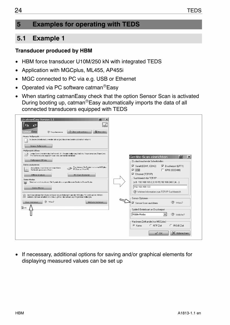
5.1 Example 1
Transducer produced by HBM
• HBM force transducer U10M/250 kN with integrated TEDS
• Application with MGCplus, ML455, AP455i
• MGC connected to PC via e.g. USB or Ethernet
• Operated via PC software catmanEasy
• When starting catmanEasy check that the option Sensor Scan is activatedDuring booting up, catmanEasy automatically imports the data of allconnected transducers equipped with TEDS
• If necessary, additional options for saving and/or graphical elements fordisplaying measured values can be set up

25TEDS
A1813-1.1 en HBM
• Implementation of a zero adjustment possible by clicking on the symbolshown below (catmanEasy channel settings)
ZEROING
NOTE:
A zero adjustment is generally not stored in the TEDS memory as this isdependent on the installation situation of the transducer. If, in specialindividual cases, the zero adjustment must be stored in the TEDS memory,an explicit value can be entered as a zero offset or tare.
This is implemented in the TEDS Editor (not a catmanEasy component)on the ”Signal processing” tab. This creates an additional HBM specifictemplate which can then only be interpreted by HBM measuring amplifiers.It is ignored by other measuring amplifiers.
Notes:
• TEDS can also be used with catmanProfessional, but the command forimporting in the TEDS memory must be given explicitly. When using themeasuring amplifier system MGCplus, this occurs via the MGCplusAssistant software included in catmanProfessional, information can befound in Example 2.
• The TEDS Editor is needed to change any TEDS data stored in thetransducer.
This is called up via the MGCplus Assistant when the measuring amplifiersystem MGCplus is used, see Chapter 3.

26 TEDS
A1813-1.1 enHBM
5.2 Example 2
Transducer produced by operator
• HBM pressure transducer P3MB / 100bar, TEDS module installed byoperator
• Application with MGCplus, ML30B, AP01i
• Operation via AB22A display and control panel
1. Writing the TEDS memory content with the TEDS Editor
To make TEDS available, the transducer data must be written once to theTEDS memory of the transducer. Changes are possible at a later date.
• MGC connected to PC (e.g. USB or Ethernet interface)
• PC has the MGCplus Assistant software (included in the MGC scope ofdelivery, also available as a download from www.hbm.com). This exampleis described using version 3.3.
• The USB driver software is also available as a download fromwww.hbm.com.
• The operator must log on as the administrator
(MGCplus Assistent- OPTIONS – User administration - TEDS)
Changing user administrationonly becomes effective afterrestarting the program.
NOTE

27TEDS
A1813-1.1 en HBM
Step I (in the MGCplus Assistant):
• In the view ”Transducer”, right click in the column ”Sensor” on the channelthat the TEDS transducer is connected to (here: Channel 3)
• In the subsequent context menu, select the menu item ”Edit TEDS”
• This starts the TEDS Editor
Step II (in the TEDS Editor)
• Click on ”HBM view”
• Left click on the field ”TEDS content new”
• In the subsequent dialog, select the force transducer type P3MB
Force transducerP3MB

28 TEDS
A1813-1.1 enHBM
• Enter the serial number in the form in the upper section of the screen
• Select the card file ”General”, enter the date of the last calibration (e.g.date of a works calibration or DKD calibration or, if these are not available,the date of the HBM test certificate) and enter the calibration initials toidentify the person or body that implemented the calibration.
Enter the recalibration deadline following the quality managementguidelines at the operator in days. Any text up to 46 characters long can beentered for the channel name. This can be a designation of the transduceror a designation of the measuring point (e.g.: ”Pump inlet”). Note, for longcharacter strings, that the display of the MGCplus itself is limited by theAB22A to 19 characters.

29TEDS
A1813-1.1 en HBM
• Select the card file ”Characteristic curve”, enter the nominal measuringrange of the transducer and the respective sensitivity (from the testcertificate or calibration certificate).
With the nominal measuring range, it must be noted that values must beentered with the Pascal unit (1 bar = 100000 Pa), in this case10 MPa.
NOTE:
The general unit bar is not supported because of the Standard IEEE1451.4. However, to display the unit bar, the additional HBM specificTemplate Unit Conversion is used. This is available by default and set upfor Pascal/bar conversion in the templates for TEDS contents that aresupplied since the version 1.0.1 of the TEDS Editor / version 1.2.7 of theMGCplus Assistant. Furthermore, the firmware used in the amplifier shouldat least comply with the version specified belows.
Single-channel modules (MLxxB) P5.50
ML455 P6.28ML460 P1.24
ML801B P6.26

30 TEDS
A1813-1.1 enHBM
• Click on the ”Store and activate TEDS” button to write the entered datainto the transducer TEDS memory and import them into the measuringamplifier. Measuring can now take place, the TEDS Editor can beterminated.
• If necessary, implement zero adjustment in the MGCplus Assistant (view”Signal processing”, column ”Zero value” or ”Tare value”; either enter avalue in the column Zero value/Tare value or zero using the displayedbutton).
NOTE:
A zero adjustment is generally not stored in the TEDS memory as this isdependent on the installation situation of the transducer. If, in specialindividual cases, the zero adjustment must be stored in the TEDS memory,an explicit value can be entered as a zero offset or tare.
This is implemented in the TEDS Editor on the ”Signal processing” tab.This creates an additional HBM specific template which can then only beinterpreted by HBM measuring amplifiers. It is ignored by other measuringamplifiers.

31TEDS
A1813-1.1 en HBM
2. Renewed setting up of the measurement chain in TEDSOnce the data has been stored in the TEDS memory, the route via the TEDSEditor is no longer required. Importing of the TEDS data and automatic set upof the measuring amplifier can be easily implemented via the AB22Adisplay/control panel or – when using a PC for measurement data acquisition– via MGCplus.
2.1 Setting up via the AB22A display/control panel:
• Connect the transducer to the measuring device
• Display the channel to which the TEDS transducer is connected on thedisplay (select with the channel selection buttons)
Channelselectionbuttons
• Press the function key ”TEDS”
(With the default key settings for the display, this function key can bereached by first pressing F4 to display the second level of key assignmentsand then pressing F2)
Please note:
With older firmware, the function key is designated with the name ”IDENT”instead of ”TEDS”
• If necessary carry out a zero adjustment

32 TEDS
A1813-1.1 enHBM
F-keys-level 1
TEDS unit . . .
F-keys-level 2Acal
-> 0 <- -> T <- -II-
P3MB Pump inlet Gross
Channel
measure
F-keys-level 1
-> 0 <- -> T <- -II-
P3MB Pump inlet Gross
measure
Channel
2.1 Setting up via the MGCplus Assistant software:
• Connect the transducer to the measuring device
• Start the Assistant (can also be implemented before connecting thetransducer)
• Select the channel to which the TEDS transducer is connected in theAssistant (view ”Transducer”, see Page 27)
• Right click on the field in which the transducer serial number is displayed;in the subsequent context menu select the menu item ”Set up channel fromTEDS”
• If necessary carry out a zero adjustment (see Page 30)
(View ”Signal processing”, column ”Zero value” or ”Tare value”)

33TEDS
A1813-1.1 en HBM
6 Specifications
Type TEDS memory module in transducercable
Data transferTo switch from measurement mode to datamode in order to transfer TEDS data
Apply a supply voltage between one ofthe excitation voltage lines (HBM des-ignation: 2) and the associated sensor
circuit (HBM designation: 2‘ ).The sensor circuit then acts as the sig-nal lead and the excitation voltage line
as the ground.If this voltage is no longer present, the
module switches to measurementmode, in which it no longer interactswith the excitation voltage and the
measurement signal.
Nominal value of supply voltage for TEDS datamemory
V 5
Working range of supply voltage for TEDS datamemory
V 3.4 ... 6.0
Data transfer protocol As specified in IEEE standard 1451.4(”one wire protocol”).
Data format As specified in IEEE standard 1451.4
Maximum permissible excitation voltagefor the motherboardfor transducers with integrated TEDS
VV
30Dependent on transducer
Nominal temperature range oC -20 ... + 60
Storage temperature range oC -25 ... +70
DimensionsMotherboardMetal sleeve (when installed by HBM)
mmmm
20x 5.593 long, Ø 15
Protection class(When installed in metal sleeve by HBM)
IP54
EMC conformance When installed in metal sleeve byHBM, EN 61326 is complied with.
This ensures that the TEDS modulehas no effect on conformance of thewhole system with EMC Guideline
89/336/EEC.

34 TEDS
A1813-1.1 enHBM

35TEDS
A1813-1.1 en HBM

Hottinger Baldwin Messtechnik GmbH
PO Box 10 01 51, D-64201 Darmstadt, GermanyIm Tiefen See 45, D-64293 Darmstadt, GermanyTel.: +49 6151 8030; Fax: +49 6151 80 39 100E-mail: [email protected] www.hbm.com
Modifications reserved.All details describe our products in general form only. They arenot to be understood as express warranty and do not constituteany liability whatsoever.
A1813-1.1 en