Tecom GSM FCT-Trunk Manual
29
Tecom GSM FCT-Trunk Manual
Transcript of Tecom GSM FCT-Trunk Manual

Tecom GSM FCT-Trunk Manual
TECOM CO., LTD.
1
CONTENT
0. DOCUMENT CONTROL.............................................................................................................................. 3
0.1 SCOPE .................................................................................................................................................... 30.2 ABBREVIATIONS..................................................................................................................................... 3
1. INTRODUCTION........................................................................................................................................... 5
2. INSTALLATION............................................................................................................................................. 6
2.1 SYSTEM INSTALLATION.................................................................................................................. 82.2 INSTALLATION TEST ........................................................................................................................ 8
3. STATUS LAMP ............................................................................................................................................. 10
4. OPERATION................................................................................................................................................. 11
4.1 STANDBY .......................................................................................................................................... 114.2 RECEIVE A CALL............................................................................................................................. 11
4.2.1 RECEIVE A CO CALL............................................................................................................... 114.2.2 RECEIVE A MO CALL .............................................................................................................. 11
4.3 MAKE A CALL.................................................................................................................................. 114.3.1 MAKE A CO CALL.................................................................................................................... 114.3.2 MAKE A MO CALL ................................................................................................................... 11
4.4 CALL WAITING ................................................................................................................................ 124.4.1 CALL WAITING FOR A MO CALL ........................................................................................... 124.4.2 CALL WAITING FOR A CO CALL............................................................................................ 12
4.5 ROUTING POLICY AND LCR(LEAST COST ROUTING) ............................................................ 124.5.1 ROUTING POLICY ................................................................................................................... 144.5.2 ROUTING TABLE...................................................................................................................... 144.5.3 LCR............................................................................................................................................ 14
4.6 GPRS (OPTIONAL) ............................................................................................................................... 15
5. PROGRAMING .......................................................................................................................................... 164
5.1 ENTER PROGRAMMING MODE .................................................................................................. 1645.2 PROGRAMMING DESCRIPTION.................................................................................................. 175
5.2.1 DIALING PROCESS SETTING ................................................................................................. 175.2.1.1 MO OUTGOING-CALL RESTRICTED TABLE (MR TABLE) ............................................155.2.1.2 MO OUTGOING-CALL ALLOWED TABLE (MA TABLE) ................................................175.2.1.3 CO OUTGOING-CALL RESTRICTED TABLE (CR TABLE)............................................1865.2.1.4 DIALING-DIGIT LENGTH TABLE (DL TABLE) ................................................................185.2.1.5 LCR TABLE .........................................................................................................................1975.2.1.6 ROUTING POLICY ................................................................................................................175.2.1.7 LEAST DIALING-DIGIT LENGTH (LEAST DIGITS) .........................................................185.2.1.8 MO FAILURE TO CO........................................................................錯誤! 尚未定義書籤。8
5.2.2 CALL HANDLING SETTING .................................................................................................... 205.2.2.1 GSM RS232 SWITCH ..............................................................................................................205.2.2.2 RELAY SWITCH ..................................................................................................................2085.2.2.3 MO RECEIVING VOLUME...................................................................................................195.2.2.4 MO TRANSMITTING VOLUME.........................................................................................2195.2.2.5 CALL WAITING .....................................................................................................................215.2.2.6 CALLER ID TYPE..................................................................................................................215.2.2.7 DIALING TYPE ......................................................................................................................205.2.2.8 POLARITY REVERSAL ........................................................................................................205.2.2.9 RINGER...................................................................................................................................225.2.2.10 MO OUTGOING-CALL PROMPT ......................................................................................225.2.2.11 CO FLASH ACTIVE ..........................................................................................................2315.2.2.12 PULSE DETECTION ...........................................................................................................215.2.2.13 METERING PULSE (OPTIONAL)....................................................................................231
5.2.3 TIME SETING ........................................................................................................................... 235.2.3.1 INTER-DIGIT TIME ............................................................................................................235.2.3.2 FLASH DETECTION TIME ..............................................................................................2425.2.3.3 TALK WARNING TIME ....................................................................................................242

TECOM CO., LTD.
2
5.2.3.4 TALK TIME..........................................................................................................................245.2.3.5 BUSY TONE TIME ............................................................................................................2535.2.3.6 SIREN TONE TIME ...........................................................................................................2535.2.3.7 RING ABANDIN TIME .......................................................................................................235.2.3.8 CO CALL FLASH TIME....................................................................................................253
5.2.4 SYSTEM SETTING .................................................................................................................... 265.2.4.1 PLMN POLICY (SIM LOCK) .............................................................................................2645.2.4.2 SIM PIN................................................................................................................................2645.2.4.3 WARM START ...................................................................................................................2645.2.4.4 PROGRAMMING PASSWORD.........................................................................................2755.2.4.5 ROUTING PROFILE..........................................................................................................2755.2.4.6 FACTORY DFAULT.............................................................................................................255.2.4.7 MO NETWORK SELECTION (GSM OPERATOR LOCK)................................................265.2.4.8 MO INCOMING-CALL END/REJECT SELECTION.........................................................26
6. APPENDIX TABLES AT FACTORY DEFAULT ..............................................錯誤! 尚未定義書籤。7
APPENDIX A: ROUTING TABLE .............................................................................錯誤! 尚未定義書籤。7APPENDIX B: DL TABLE SET..................................................................................錯誤! 尚未定義書籤。7APPENDIX C: MA TABLE SET.................................................................................錯誤! 尚未定義書籤。7APPENDIX D: MR TABLE SET.................................................................................錯誤! 尚未定義書籤。8APPENDIX E: CR TABLE SET..................................................................................錯誤! 尚未定義書籤。8APPENDIX F: LCR TABLE SET................................................................................錯誤! 尚未定義書籤。8
TECOM CO., LTD.
3
0. Document Control
0.1 ScopeThe document is an installation operation manual of the product, FCT-Trunk. Itspecifies installation and user operations about FCT-Trunk.
0.2 AbbreviationsCID: Caller IDentificationCO: Central Office (Fixed Line Network)CR Table: CO Outgoing-Call Restricted TableDL Table: Dialing-Digit Length TableFCT: Fixed Cellular TerminalIMSI: International Mobile Subscriber IdentityIP: Internet ProtocolLCR: Least Cost RoutingMA Table: MO Outgoing-Call Allowed TableMR Table: MO Outgoing-Call Restricted TableMCC: Mobile Country CodeMNC: Mobile Network CodeMO: MObile (Mobile Network)PBX: Private Branch ExchangePDP: Packet Data ProtocolPIN: Personal Identification NumberPLMN: Public Land Mobile NetworkPSTN: Public Switch Telephone NetworkSLT: Single Line TelephoneWLL: Wireless Local LoopRSSI: Receiver Signal Strength Indicator
TECOM CO., LTD.
4
PRODUCT CARE
- Please review the simple guideline below. Failure to comply with the guideline maybe dangerous or illegal.
- All radio/wireless equipment may be subject to radio interference, which may affectthe performance.
- The product may be installed and repaired by the qualified service personnel only.
- Do not keep the product near with tinder.
- The product might affect the operation of medial equipment in hospital. Please followthe regulations or rules in force.
- Do not expose the product in the environment with water, moisture, or duct.
- Do not expose the product at extreme high or low temperature. Exposing the productat that environment may reduce the life span of electronic material, cause the productdamage, or degrade the product performance.
- Do not attempt to disassemble the product. Doing so my cause the damage ofelectronic material.
- Use the original accessories. Failure to do so may cause in performance degradation,fire, electric shock, or injury. Manufacturer assumes no responsibility with regard tothe use of the non-original accessories.
TECOM CO., LTD.
5
1. INTRODUCTIONTecom GSM FCT-Trunk is an advanced fixed GSM-cellular terminal. This productmay allow fixed line PBX(or SLT) users to make calls or receive calls via GSMmobile network without re-setting the PBX system, changing the dialing behavior,and reducing PBX fixed line ports.
The product provides both GSM MO and fixed line CO ports. With built-in routingfeature, it automatically routes the calls to either GSM network, or fixed line network.And it may be easily and cost-effectively deployed, once the route-selection policyis determined via pre-programmed.
The GPRS is also supported (optional). This multi-function product may be usedas a fixed wireless terminal under GSM-based WLL network, or/and can be used ascost saver, or a service provider selector among all GSM network and fixed linenetworks.
Main features of Tecom GSM FCT-Trunk:ν Support dual-mode GSM(900/1800MHz, or 850/1900Mhz), and fixed line
service.ν Support GPRS (optional).ν RJ11 and RS232 interfaces, plug-play installation.ν Provide back-up battery contact.ν Programmable routing selection and LCR functions.ν Customized routing policy.ν Provide SIM lock function.ν Provide fast dialing function.ν MO/CO call waiting.ν Provide polarity reversal(PR) signal.ν Support DTMF/FSK Caller ID service.ν Support DTMF/Pulse dialing.ν Fast profile setting for LCR tables and routing prefix tables.ν Programming via regular telephone, or PC.ν Remote programming capability.
TECOM CO., LTD.
6
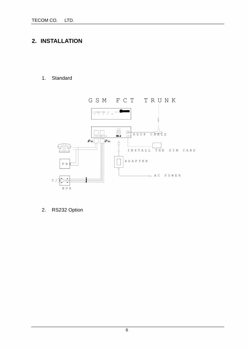
2. INSTALLATION
1. Standard
T/R
INSTALL THE SIM CARD
ADAPTER
BOX
PBX
AC POWER
RG58 CABLE
GSM FCT TRUNK
PHONE
POWER
LINE
MOSTATUS RSSICO
ANT
2. RS232 Option
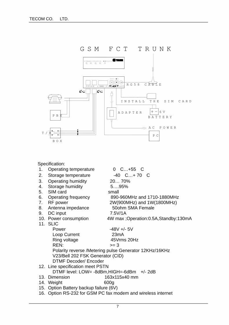
TECOM CO., LTD.
7
PHONE LINE ANT
PBX
T/R
BOX
POWER STATUS MO CO
RG58 CABLE
GSM FCT TRUNK
ADAPTER
AC POWER
INSTALL THE SIM CARD
RSSI
RS-232
PC
BATTERY
6V
Specification:1. Operating temperature 0° C…+55° C2. Storage temperature -40° C…+ 70° C3. Operating humidity 20… 70%4. Storage humidity 5….95%5. SIM card small6. Operating frequency 890-960MHz and 1710-1880MHz7. RF power 2W(900MHz) and 1W(1800MHz)8. Antenna impedance 50ohm SMA Female9. DC input 7.5V/1A10. Power consumption 4W max ;Operation:0.5A,Standby:130mA11. SLIC
Power -48V +/- 5VLoop Current 23mARing voltage 45Vrms 20HzREN: >= 3Polarity reverse /Metering pulse Generator 12KHz/16KHzV23/Bell 202 FSK Generator (CID)DTMF Decoder/ Encoder
12. Line specification meet PSTNDTMF level: LOW= -8dBm,HIGH=-6dBm +/- 2dB
13. Dimension 163x115x40 mm14. Weight 600g15. Option Battery backup failure (6V)16. Option RS-232 for GSM PC fax modem and wireless internet

TECOM CO., LTD.
8
2.1 SYSTEM INSTALLATION1. Insert the SIM card first.
Warning : to avoid the product damaged, please insert SIM cardbefore power-on, and power-off first if it is necessary to takeSIM card out of the product.。
2. Install the antenna. Be sure the antenna connector is fixed properly. The guideline to install the antenna is listed below:
(1) It’s better to place the antenna near to the window that is close to radio base station.(2) Do not put the antenna at some place with obstruction.(3) Do not put the antenna holdfast-disk on high power equipment such as air
conditioner, microwave, computer, ..etc.(4) It’ better to put the antenna much far way from phone or PBX, to avoid any
interference.3. Connect to PSTN CO line to the “LINE” of GSM FCT-Trunk.4. Connect to the phone(DTMF type) or PBX to the “PHONE” of GSM FCT-Trunk.
The specification of PHONE end(When LINE end is not connected to CO) is:(1) Voltage − 48V ± 5V(2) Ringing Voltage 45Vrms20Hz(3) REN ≥ 3(4) The supported distance(between GSM FCT-Trunk and phone/PBX): 1Km
5. Connect to the power line of power adapter to “DC IN 7.5V” of GSM FCT-Trunk, and plug the power adapter into power outlet.
6. The operation temperature ranges from 0°C ~ 55°C.7. Once the power is shut down, the system remains the PSTN CO line
workable.8. The external battery will be charged while used. The acid-lead battery of
6V/3-5Ah is recommended. Warning : be sure to connect with correct battery polarity.
2.2 INSTALLATION TEST1. Make a call
(1) Will hear a dial tone after the handset is lifted (may hang up, and lift thehandset later when hearing a busy signal).(2) Dial the number. The call will be gotten through after 5-6 seconds(Pressing “#” after the number dialed may speed the dialing process).
2. Receive a callMay answer the call after lifting the handset when hearing a ring.
3. CID displayNeed to work with CID enabled SLT or PBX. DTMF or FSK format issupported. The default is set at DTMF.
4. PBXThe operation remains same after the product is installed.
5. For the GPRS application, please refer to section 4.6.
Note : During the process of making/receiving a call, the installer

TECOM CO., LTD.
9
may also tell if the product is installed correctly from thestatus lamp. Please refer to section 3.
Note : Some of PBX will do the polarity detection during installation.If it is found not to be able to make a C.O. call, it may bedue to the wrong polarity on the C.O. line. Please revisethe polarity of the line to try again.
TECOM CO., LTD.
10
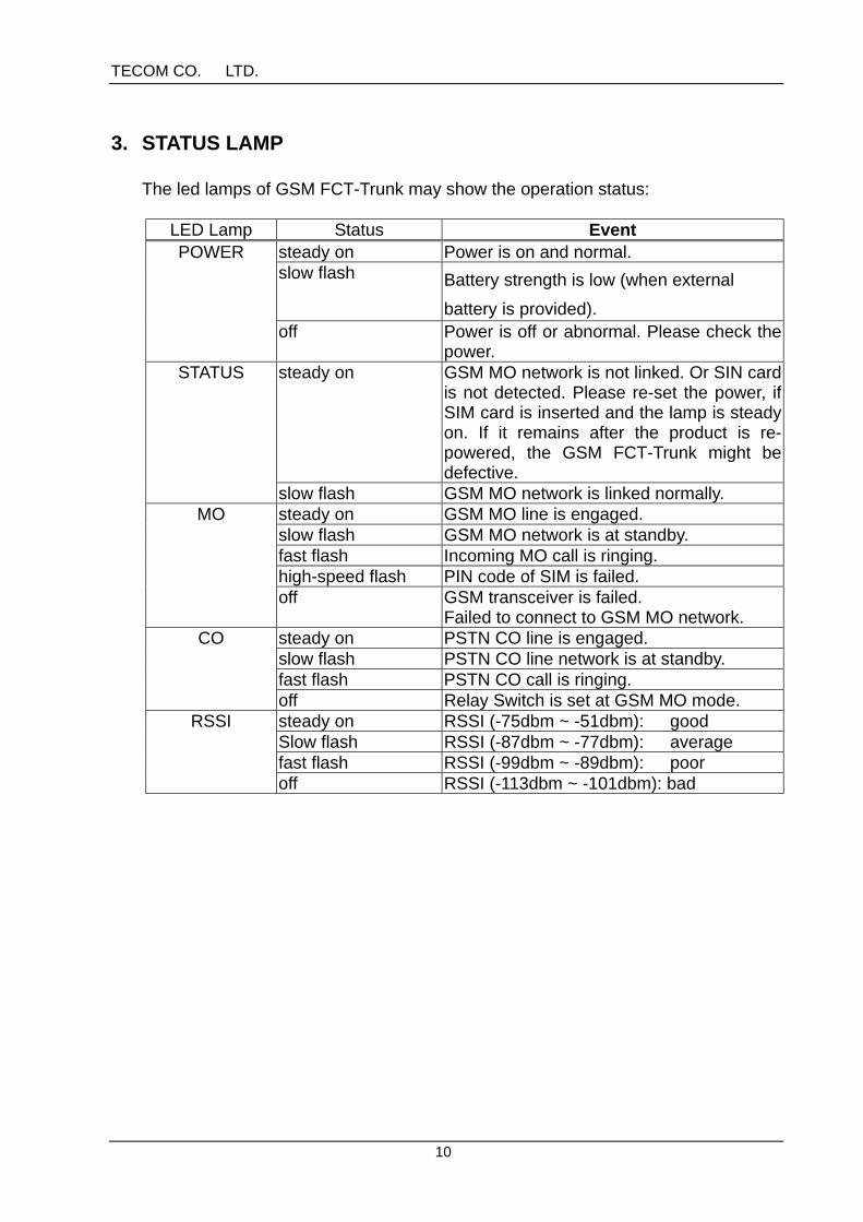
3. STATUS LAMP
The led lamps of GSM FCT-Trunk may show the operation status:
LED Lamp Status Eventsteady on Power is on and normal.slow flash Battery strength is low (when external
battery is provided).
POWER
off Power is off or abnormal. Please check thepower.
steady on GSM MO network is not linked. Or SIN cardis not detected. Please re-set the power, ifSIM card is inserted and the lamp is steadyon. If it remains after the product is re-powered, the GSM FCT-Trunk might bedefective.
STATUS
slow flash GSM MO network is linked normally.steady on GSM MO line is engaged.slow flash GSM MO network is at standby.fast flash Incoming MO call is ringing.high-speed flash PIN code of SIM is failed.
MO
off GSM transceiver is failed.Failed to connect to GSM MO network.
steady on PSTN CO line is engaged.slow flash PSTN CO line network is at standby.fast flash PSTN CO call is ringing.
CO
off Relay Switch is set at GSM MO mode.steady on RSSI (-75dbm ~ -51dbm): goodSlow flash RSSI (-87dbm ~ -77dbm): averagefast flash RSSI (-99dbm ~ -89dbm): poor
RSSI
off RSSI (-113dbm ~ -101dbm): bad

TECOM CO., LTD.
11
4. OPERATION
4.1 STANDBYWhen the system is at normal standby, the led lamps will show:
ν POWER steady on: Power is normal.ν STATUS slow flash: GSM network is linked normally.ν MO slow flash: GSM MO network is at standby.ν CO slow flash: PSTN CO network is at standby.ν RSSI steady on : Good GSM network
4.2 RECEIVE A CALLLift the handset to answer the call when hearing a ring.
4.2.1 RECEIVE A CO CALLWhen an incoming CO call is ringing(CO lamp will change the status from slowflash to fast flash), called party may lift handset to answer the phone(CO lamp willchange the status from fast flash to steady on).
4.2.2 RECEIVE A MO CALLWhen an incoming MO call is ringing(MO lamp will change the status from slowflash to fast flash), called party may lift handset to answer the phone(MO lamp willchange the status from fast flash to steady on).
4.3 MAKE A CALLBe sure the product is at normal standby before make a call. There are two ways tocomplete the call dialed out:1. Detection dialing: The product will automatically send out the number after
detecting the complete dialing which caller makes.2. Speed dialing: The product will send out the number immediately once
caller party press “#” to end the phone number dialed(Note:The “#” will not be sent out from the product in the case).
Warning : The speed dialing key “#” will take effect only forcaller party to press “#” after a minimum of threedialed-out digits.
4.3.1 MAKE A CO CALLWhen caller makes a dial after lifting the handset and hearing the dial tone, it will bemaking a CO call if CO lamp changes the status to steady on. To end the call, justhang up.
4.3.2 MAKE A MO CALLWhen caller makes a dial after lifting the handset and hearing the dial tone, it will bemaking a MO call if MO lamp changes the status to steady on. To end the call, just

TECOM CO., LTD.
12
hang up.
Warning : For an outgoing call routed to GSM MO network, caller will hear a Di Di alert tone.
4.4 CALL WAITINGThe call waiting is disabled at default. To enable this function, please see section5.2.2.4 about the setting.
4.4.1 CALL WAITING FOR A MO CALLWhen user is engaged in a CO call(CO lamp shows steady on), if an incoming MOcall is in(MO lamp shows fast flash), user will hear Do Do alert tone(for each 10seconds). In the case, user may place the CO call on hold, and answer theincoming MO call via pressing “FLASH”(a hook-switch signal). And user mayswitch back to answer the CO call, and place the MO call on hold via pressing“FLASH” again.
4.4.2 CALL WAITING FOR A CO CALLWhen user is engaged in a MO call(MO lamp shows steady on), if an incoming COcall is in(CO lamp shows fast flash), user will hear Do Do alert tone(for each 10seconds). In the case, user may place the MO call on hold, and answer theincoming CO call via pressing “FLASH”. And user may switch back to answer theMO call, and place the CO call on hold via pressing “FLASH” again.
4.5 ROUTING POLICY AND LCR(LEAST COST ROUTING)When caller make an outgoing call, FCT-Trunk will route the call to either fixed lineCO network, or GSM MO network. User does not need to change the dialingbehavior. The outgoing route is determined by FCT-Trunk with pre-programmedrouting mechanism.
TECOM CO., LTD.
13
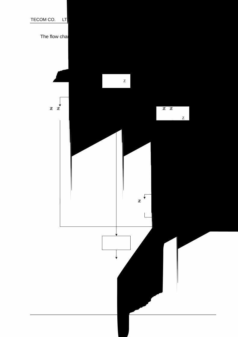
The flow chart below shows the routing mechanism of FCT-Trunk:
D ialing
M R Table
A ll calls routedto G S M M Onetw ork
A ll calls routedto Fixed Line C O
netw ork
M A Table
C R Table
LC R
C allrestricted
R outing P olicy
C all routed toG S M M Onetw ork
C all routed toFixed Line C Onetw ork
D eterm ineoutgoing route
A ll calls routedaccording toR outing Table
TECOM CO., LTD.
14
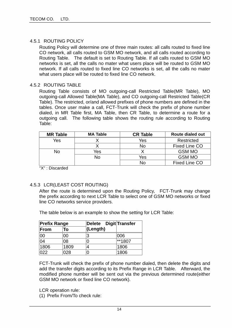
4.5.1 ROUTING POLICYRouting Policy will determine one of three main routes: all calls routed to fixed lineCO network, all calls routed to GSM MO network, and all calls routed according toRouting Table. The default is set to Routing Table. If all calls routed to GSM MOnetworks is set, all the calls no mater what users place will be routed to GSM MOnetwork. If all calls routed to fixed line CO networks is set, all the calls no materwhat users place will be routed to fixed line CO network.
4.5.2 ROUTING TABLERouting Table consists of MO outgoing-call Restricted Table(MR Table), MOoutgoing-call Allowed Table(MA Table), and CO outgoing-call Restricted Table(CRTable). The restricted, or/and allowed prefixes of phone numbers are defined in thetables. Once user make a call, FCT-Trunk will check the prefix of phone numberdialed, in MR Table first, MA Table, then CR Table, to determine a route for aoutgoing call. The following table shows the routing rule according to RoutingTable:
MR Table MA Table CR Table Route dialed outX Yes RestrictedYesX No Fixed Line CO
Yes X GSM MOYes GSM MO
NoNo
No Fixed Line CO"X" : Discarded
4.5.3 LCR(LEAST COST ROUTING)After the route is determined upon the Routing Policy, FCT-Trunk may changethe prefix according to next LCR Table to select one of GSM MO networks or fixedline CO networks service providers.
The table below is an example to show the setting for LCR Table:
Prefix RangeFrom To
Delete Digit(Length)
Transfer
00 00 3 00604 08 0 **18071806 1809 4 1806022 028 0 1806
FCT-Trunk will check the prefix of phone number dialed, then delete the digits andadd the transfer digits according to its Prefix Range in LCR Table. Afterward, themodified phone number will be sent out via the previous determined route(eitherGSM MO network or fixed line CO network).
LCR operation rule:(1) Prefix From/To check rule:
TECOM CO., LTD.
15
The prefix dialed is checked according to From/To Prefix Range digit by digitfrom the beginning digit. The value of each digit of “To Prefix” should not be setsmaller than that of each digit of “From Prefix” digit by digit. If a prefix range of“047” ~ “052” needs to be set, it can be done via setting From/To Prefix ofboth 047/049(Prefix Range: 047, 048, 049) and 050/052(Prefix Range: 050,051, 052). The numbering from small to large is 0,1,2,3,、、、,9,*,#.
(2) After checking the prefix range, FCT-Trunk will delete a certain digit(s),according to associated “delete digit length”, of dialed number from thebeginning digit.
(3) Then, FCT-Trunk will insert “Transfer Digit” at the beginning of number to besent out, If Transfer is set staring with “*”, “Transfer” will be inserted after thefirst digit. If Transfer is set staring with “**”, “Transfer” will be inserted after thesecond digit…..and so on.
Example:From Prefix: 04To Prefix: 08Delete Digit: 0Transfer: **1807If caller dials “0412345678”,the “04180712345678” will be sent out fromGSM FCT-Trunk after adjusted via LCR.
4.6 GPRS(optional)FCT-Trunk may support GPRS service provided by GSM MO operator.
【Operation】Step 1: Connect FCT TRUNK(RS232 data port) to Windows-based PC.Step 2: Refer to Section 5.2.2.1 to set GSM RS232 Switch at 1.Step 3: Set GSM FCT-Trunk Configuration by using a terminal program such as
Hyperterminal in PC:(1) Select PC baud rate at 9600 bps(2) Enter PDP(Packet Data Protocal) command:
at+cgdcont=1,”IP”,”Access Point Name”Note: Access Point Name, provided by GPRS service operator, is a
string parameter used to select the gateway GPRS Support Node.
(3) Enter the command for the minimum quality of service:at+cggreq=1,0,0,3,0,0
(4) Set GSM FCT-Trunk baud rate at 115200 bps:at+ipr=115200
(5) Close the terminal program.Step 4: Add new Modem, FCT-Trunk, in PC:
Start/Settings/Control Panel/Modem/AddNote: Click Standard 19200 bps Modem if the manufacturer/model of
new modem is requested while in setting.Step 5: Set-up a Dial-Up Networking Connection, in PC:
Start/Programs/Accessories/Communications/Dial-Up Network/MakeNew ConnectionNote: Select the Standard 19200 bps Modem, set the baud rate at

TECOM CO., LTD.
16
115200 bps, and the telephone number at *99***1#.Step 6: Click the created Dial-UP Networking Connection to connect the GPRS
network.Note: Once FCT-Trunk is added in the modem list, and a Dial-Up Network
Connection is built at first time, user may skip above Step 4 and 5 whileusing GPRS again.
5. PROGRAMMING
5.1 ENTER PROGRAMMING MODETo program the product is possible via following three methods:1. Local Single Line TelephoneUser may program the setting via phone connected to RJ11 phone port of FCT-Trunk. Be sure to connect the PSTN CO line to Line port of GSM FCT-Trunk priorto programming.
【Operation】Step 1: Lift the handset.Step 2: Press “*#***8326#”. (It is successful to enter programming mode if a Di Di alert tone is heard.)Step 3: Press the programming command and parameters. (For the detailed programming, please refer to Section 5.2.)
【Note】8326 is a password to enter programming mode at default.
2. Remote ProgrammingUser may program the setting from a remote telephone terminal phone via GSMMO network.
【Operation】Step 1: Dial out to FCT-TrunkStep 2: Press “*#***8326#” when called party picks up the call at FCT-Trunk (It is successful to enter programming mode if a Di Di alert tone is heard.)Step 3: Press the programming command and parameters (For the detailed programming, please refer to Section 5.2.)
【Note】Called party may hang up the phone during the programming period after theprogramming mode is entered.
3. PCUser may also program the setting from a local PC via a serial RS232 cable. Theprogramming jig and PC programming software are required for this PC setting.Please refer to the manual of FCT-Trunk PC program for the details if necessary.

TECOM CO., LTD.
17
5.2 PROGRAMMING DESCRIPTION【Setting Format】* #CC#P1*P2*P3*P4*P5*#
【Definition】*: It is used to separate the parameter.#: it is used to end the setting.CC:The command item is programmed to two digits.P1、P2、….P5: Those are the parameters to be inputted.
Warning : A Di confirmation tone will be heard if the setting is successfully programmed; otherwise, a Di Di error tone will be heard.
5.2.1 DIALING PROCESS SETTINGThis section describes Table Setting and General Setting listed below:
Table Setting:- Routing Table (MR Table, MA Table and CR Table)- DL Table- LCR Table
General Setting:- Routing Policy- Least Digits- MO Failure to CO
5.2.1.1 MO OUTGOING-CALL RESTRICTED TABLE(MR TABLE)MR Table is used to set the prefix restricted to dial-out via GSM MO network.
【Operation】Add the prefix entry: Press*#41#1*Prefix(1~6 digits)#Delete prefix entry: Press*#41#0*Prefix#Delete all entries: Press*#41#99#
【Note】1. If set via PC, the prefix may contain the* and #, and the number of 0~9.2. Up to 28 prefix entries may be set in MR Table.
5.2.1.2 MO OUTGOING-CALL ALLOWED TABLE(MA TABLE)MA Table is used to set the prefix allowed to dial-out via GSM MO network.
【Operation】Add the prefix entry: Press*#40#1*Prefix(1~6 digits)#Delete prefix entry: Press*#40#0*Prefix#Delete all entries: Press*#40#99#
TECOM CO., LTD.
18
【Note】1. Appendix C is MA Table at default.2. If set via PC, the prefix may contain the* and #, and the number of 0~9.3. Up to 28 prefix entries may be set in MR Table.
5.2.1.3 CO OUTGOING-CALL RESTRICTED TABLE(CR TABLE)CR Table is used to set the prefix restricted to dial-out via fixed line CO network.
【Operation】Add the prefix entry: Press*#42#1*Prefix(1~6 digits)#Delete prefix entry: Press*#42#0*Prefix#Delete all entries: Press*#42#99#
【Note】
1. If set via PC, the prefix may contain the* and #, and the number of 0~9.2. Up to 12 prefix entries may be set in CR Table.
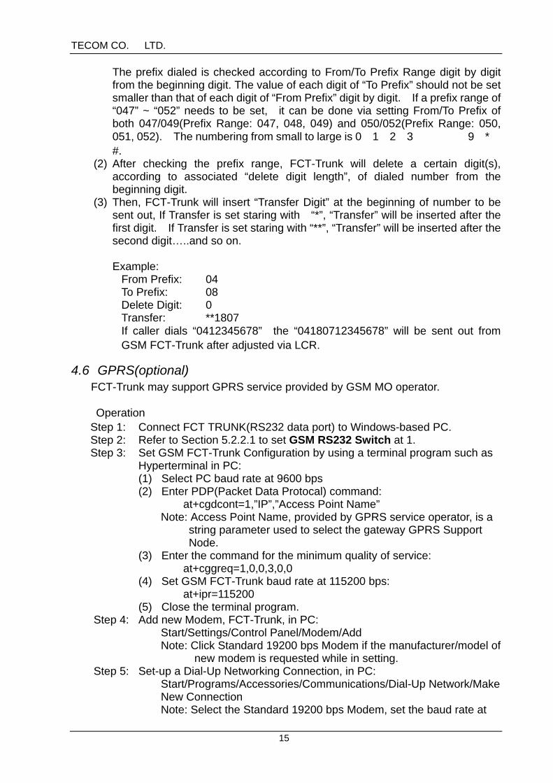
5.2.1.4 DIALING-DIGIT LENGTH TABLE(DL TABLE)This DL Table is used to set the length of dialing-digit according to the prefix. FCT-Trunk will send out the number right after it detects the number dialed is completeaccording to DL Table. Take the following DL Table for example:
PrefixEntry
From ToLength
1 02 02 102 03 03 93 042 043 10
Once caller dials 035775141,FCT TRUNK will check the prefix, 03, to know thelength of complete digits is 9, and will send out the phone number, 035775141,immediately when it detects the ninth digit, 1, is dialed.
【Operation】Add prefix entry: Press*#43#1*Prefix From(1~4 digits)*Prefix To(1~4
digits)*Length(1~99)#Delete prefix entry: Press*#43#0*Prefix From*Prefix To#Delete all entries: Press*#43#99#
【Note】1. If set via PC, the prefix may contain the* and #, and the number of 0~9.2. Up to 14 prefix From/To entries may be set in DL Table.

TECOM CO., LTD.
19
5.2.1.5 LCR TABLELCR Table is used to set the digits(Transfer) which be added on(or inserted into) thenumber dialed. GSM FCT-Trunk may change the prefix to select a service providerfor a least cost routing according to the pre-programmed LCR Table.
Example:Prefix(From)
Prefix(To)
DeleteDigit(Length)
Transfer Number dialed(example)
Number adjusted
02 03 0 1807 035775141 180703577514104 08 0 **1807 041234678 04180712345678002 002 3 005 002861065032280 005861065032280
【Operation】Add prefix entry: Press*#44#1*Prefix From(1~6 digits)*Prefix To(1~6 digits)*Delete Digit(Length 0~10)*Transfer(0~10 digits)#Delete prefix entry: Press*#44#0*Prefix From*Prefix To#Delete all entries: Press*#44#99#
【Operation】
1. If set via PC, the prefix From/To or/and Transfer may contain the* and #, andthe number of 0~9.
2. After deleting a certain digit(s), the digits of Transfer will be added on at thebeginning of the number to be sent out. If Transfer is set starting with “*”,Transfer will be inserted after the first digit. If Transfer is set starting with “**”,Transfer will be inserted after the second digit…..and so on.
3. Up to 12 prefix From/To entries may be set in LCR Table.
5.2.1.6 ROUTING POLICYIt is to set the policy for an outgoing-call route from FCT-Trunk.
【Operation】Press*#45#Routing Policy(0~2)#
【Note】Routing Policy:
0: The route is determined according to Routing Table(MR, MA, and CR Tables). The Routing Policy is set at default, 0.1: All the calls are routed to GSM MO network.2: All the calls are routed to fixed line CO network.
TECOM CO., LTD.
20
5.2.1.7 LEAST DIALING-DIGIT LENGTH SETTING (LEAST DIGITS)This is to set the least length of dialing digits. If caller dial a number less than“Least Digits”, the number will not be sent out from GSM FCT-Trunk.
【Operation】Press*#46#Least Digits(0~6)#
【Note】1. The Least Digits, 3, is set at default.2. There is no length limit if a 0 is set at Least Digits.
5.2.1.8 MO FAILURE TO COThis is to set the outgoing call to be automatically routed to fixed line CO network ifGSM MO network is failed. The setting is activated only the Routing Policy is set atRouting Table.
【Operation】Press*#25#MO FAILURE TO CO(0/1)#
【Note】0: disable at default 1: enable
5.2.2 CALL HANDLING SETTING
5.2.2.1 GSM RS232 SwitchThis is to set the RS232 loop of FCT-Trunk, while at standby, to either internaldevice(host), or external DTE device(such as PC). GSM RS232 Switch must beset at 0 in all cases except set at 1 for GPRS. Once the system is set for GPRS,FCT-Trunk is unable to make GSM voice call.
【Operation】Press*#47#GSM RS232 Switch(0/1)#
【Note】0: RS232 loop is connected to internal device of FCT-Trunk(host). The default is set at 0.1: RS232 loop is connected to external DTE device(such as PC).
5.2.2.2 RELAY SWITCHThis Relay Switch mechanism is used to set the operation under the modes ofeither MO network or MO/CO networks. The Relay Switch must be set to MOnetwork, if there is no CO line connected to FCT-Trunk, or not workable for sometroubles.
TECOM CO., LTD.
21
【Operation】Press*#48#Relay Switch(0/1)#
【Note】1. 0: set to CO/MO network at default, 1: set to MO
5.2.2.3 MO RECEIVING VOLUMEThis is to set the receiving volume from GSM MO network.
【Operation】Press*#49#MO Receiving Volume(0~7)#
【Note】4 is the default. 0 is the lowest. And 7 is the highest.
5.2.2.4 MO TRANSMITTING VOLUMEThis is to set the transmitting volume to GSM MO network.
【Operation】Press*#78#MO Transmitting Volume(0~7)#
【Note】3 is the default. 6 is the lowest, and 5 is the highest. (6->7->0->1->2->3->4>5).
5.2.2.5 CALL WAITINGThis function is to set the on/off of Caller Waiting between MO call and CO calls.
【Operation】Press*#50#Call Waiting(0/1)#
【Note】1. 0: disable(default), 1: enable2. If the function is disabled, user can not receive the MO(or CO) call while user is
engaged in a CO(or MO) call. And the caller placing the MO(or CO) will hear thebusy tone.
5.2.2.6 CALLER ID TYPEThis is to set the type of caller ID which phone(or PBX) may receive for a MOincoming call.
【Operation】Press*#51#Caller ID Type#
【Note】
TECOM CO., LTD.
22
0: disable1: DTMF(default)2*0: FSK Bell 2022*1: FSK V23
5.2.2.7 DIALING TYPEThis function is to set the dialing type of a CO call sent out from FCT-Trunk.
【Operation】Press*#52#Dialing Type(0/1)#
【Note】0: DTMF(default)1: Pulse
5.2.2.8 Polarity Reversal(PR)For a MO outgoing-call, FCT-Trunk may send the polarity reversal signal to thephone(or PBX), connected to FCT-Trunk, once called party hangs off to answer thecall or hangs up to end the call.
【Operation】press*#54#PR(0/1)#。
【Note】0:disable(default), 1: enable
5.2.2.9 RINGERThis function is to set the frequency, and on/off time of FCT-Trunk ringer to work withthe connected phone(or PBX) for a MO incoming-call.
【Operation】Press*#55#Frequency*On Time*Off Time*#
【Note】1. Frequency(Hz): It could be 10, 20, 25, 50, or 100. The default is 20.2. On Time(second): The period can be set from 1 to 4. The default is 1.3. Off Time(second): The period can be set from 1 to 4. The default is 4.
5.2.2.10 MO OUTGOING-CALL PROMPTThis function is to set FCT-Trunk to provide the prompt, DiDi, for a MO outgoing call.
【Operation】Press*#56#MO Prompt(0/1)#

TECOM CO., LTD.
23
【Note】0: disable1: enable(default)
5.2.2.11 CO FLASH ACTIVEThis is used to disable or enable the flash function for CO network.
【Operation】Press*#57#CO Flash Active(0/1)#
【Note】1. 0: disable(default), 1: enable2. No matter what is set, CO Flash Active will be enabled when Call Waiting function of FCT-Trunk is enabled.
5.2.2.12 PULSE DETECTIONThis function is set the pulse detection for FCT-Trunk to accept the pulse dialingfrom the phone(or PBX) connected to. If it’s enabled, FCT-Trunk may accept pulsedialing beside of DTMF dialing. If it’s disabled, FCT-Trunk will accept DTMF dialingonly.
【Operation】Press*#59#Pulse Detection(0/1)#
【Note】0: disable(default)1: enable
5.2.2.13 METERING PULSE (optional)This is to set the frequency of metering pulse at either 12KHz or 16KHz.
【Operation】Press*#53#Metering Pulse(0~2)#
【Note】0: disable(default)1: enable at 12KHz metering pulse2: enable at 16Khz metering pulse
5.2.3 TIME SETTING
5.2.3.1 INTER-DIGIT TIMEThe Inter-Digit Time is a waiting time limit for FCT-Trunk to receive each digit fromthe phone(or PBX). If FCT-Trunk does not receive the further digit within this timelimit, it will end the receiving, and immediately send out the number received
TECOM CO., LTD.
24
already.
【Operation】Press*#60#Inter-Digit Time(2~30)#
【Note】The default is 5 seconds. The interval(second) can be set from 2 to 30.
5.2.3.2 FLASH DETECTION TIMEFCT-Trunk will detect the Flash via this time interval mechanism including lowerbound interval and upper bound interval. If the Flash-on time interval is less thanlower bound time interval, FCT-Trunk will accept the Flash. If the Flash-on timeinterval is longer than upper bound time interval, FCT-Trunk will end the call.
【Operation】Press*#61#Lower Bound Time(10~140)*Upper Bound Time(20~150)#
【Note】1. Unit: 10 milliseconds2. The default Lower Bound Time is set at 20(20x10 = 200ms).3. The default Upper Bound Time is set at 80(80x10 = 800ms).4. The Lower Bound Time should be less than Upper Bound Time.
5.2.3.3 TALK WARING TIMEFCT-Trunk will invoke a warning Du tone when an outgoing-call lasts over the timelimit. And afterwards, a warning Du tone will be invoked for every 30 seconds ifoutgoing-call lasts.
【Operation】Press*#62#Talk Warning Time(0~60)#
【Note】The time limit range is between 1 and 60 (minutes), and it could be set at 0 forwithout warning tone. The default is set at 0.
5.2.3.4 TALK TIMEThis function is to set the time limit to end the outgoing-call. FCT-Trunk will invokean alert tone at 10 seconds before the time limit, and will end the outgoing-call attalk time limit.
【Operation】Press*#63#Talk Time(0~255)#
【Note】The Talk Time limit can be set at any between 1 to 255 (minutes), and it could be set
TECOM CO., LTD.
25
at 0 for without time limit. 0 is set at default.
5.2.3.5 BUSY TONE TIMEThis is to set the time interval of busy tone. FCT-Trunk will invoke a busy tone forthe designated interval if user lifts the handset without dialing any digits withinInter-Digit Time, or user dials the phone number which is restricted.
【Operation】Press*#64#Busy Tone Time(0~180)#
【Note】The time interval can be set at any between 1 and 180 (second), and it could be setat 0 for disable. 30 is set at default.
5.2.3.6 SIREN TONE TIMEThis is to set the time interval of siren tone which will be invoked while in any wrongconditions.
【Operation】press*#65#Siren Tone Time(0~180)#
【Note】The time interval can be set at any between 0 and 180 (second). 30 is set at thedefault.
5.2.3.7 RING ABANDON TIMEThis is to set the time interval of ring-off for detection. GSM FCT-Trunk will detectthe ring-off for an incoming call, and abandon the incoming call if the ring-off lastslonger than this time interval.
【Operation】Press*#66#Ring Abandon Time(5~10)#
【Note】The time interval can be set at any between 5 and 10 (second). The default is setat 6.
5.2.3.8 CO CALL FLASH TIMEThis is to set the flash timing, flash duration and call delay for CO call flash. FCT-Trunk will, before dialing out a CO call, make a flash and delay to avoid thedisconnection from CO network if user does not complete the dialing. Takefollowing setting for example:The setting,*#67#13*100*40#, means that if users do not complete a CO callwithin 13 seconds, FCT-Trunk will make 1 second flash to avoid the disconnection

TECOM CO., LTD.
26
from CO network, then dialing out the CO call after a 400 milliseconds of delay.
【Operation】Press*#67#Flash Timing*Flash Duration*Call Delay#
【Note】1. Flash Timing(second): It could be set at 0 to disable, 1 to always make a flash
before dialing out, and 8~25 for 8 seconds~25 seconds The default is set at 13.
2. Flash Duration(10 milliseconds): It could be set at 0, 60, 100, 150, 200, 250, or300. The default is set at 100 (1 second).
3. Call Delay(10 milliseconds): It could be set at 20, 20, 40, 50, 60, 70, 80, 90,100, 120 or 150. The default is set at 40 (40milliseconds).
5.2.4 SYSTEM SETTING
5.2.4.1 PLMN POLICY(SIM LOCK)This function is used to enable/disable the lock for a designated MO network serviceprovider. This function is optional and must be customized for GSM FCT-trunk tocheck both MCC and MNC of IMSI code in SIM. Please contact manufacturer forthe PLMN Policy if it’s necessary.
【Operation】Press*#30#PLMN Policy(0/1)*Locking Password#
【Note】1. PLMN Policy: 0: disable the lock
1: enable the lock2. Locking Password: It’s provided by manufacturer.
5.2.4.2 SIM PINThis is to set PIN code of SIM card for GSM FCT-Trunk.
【Operation】Press*#91#PIN(0000~9999)#
【Note】3. The default is set at 0000.4. FCT-Trunk will not check PIN, if PIN lock is disabled in SIM card.
5.2.4.3 WARM STARTThis function allows GSM FCT-Trunk to invoke a warn start.
TECOM CO., LTD.
27
【Operation】Press*#94#
5.2.4.4 PROGRAMMING PASSWORDThis function allows user to change the programming password for setting. It’s notallowed to enter the programming mode if the programming password is missed.
【Operation】Press*#95#Programming Password(0000~9999)#
【Note】The default is set at 8326.
5.2.4.5 Routing ProfileThis function of Routing Profile provides a quick way for user to set the RoutingTable(MA/MR/CR Table) and LCR Table via selecting the designated tables whichare pre-programmed at factory.
【Operation】Press*#96#T1 T2 T3 T4#
【Note】1. T1 is the MA Table index(from 0 to 9). Please refer to the appendix C for the list
of pre-programmed MA Tables.2. T2 is the MR Table index(from 0 to 9). Please refer to the appendix D for the list
of pre-programmed MR Tables.3. T3 is the CR Table index(from 0 to 9). Please refer to the appendix E for the list
of pre-programmed CR Tables.4. T4 is the LCR Table index(from 0 to 9). Please refer to the appendix F for the list
of pre-programmed LCR Tables.5. The default is set at 0000.
5.2.4.6 Factory DefaultThis function allows user to re-set FCT TRUNK at factory default.
【Operation】Press*#99#
【Note】This function will not take effect for following settings:1. MA Table2. MR Table3. CR Table4. LCR Table5. SIM PIN
TECOM CO., LTD.
28
5.2.4.7 MO Network Selection (GSM Operator Lock)GSM Operator code, a 5 or 6-digit codes, consists of MCC and MNC. FCT-Trunkwill be forced to register to the dedicated GSM MO Network if the setting of MONetwork Selection is set. This function is optional and must be customized forGSM FCT-trunk. Please contact manufacturer for the MO Network Selection if it’snecessary.
【Operation】Press*#31#MO Network Selection#
【Note】MO Network Selection is the code containing MCC plus MNC.
5.2.4.8 MO Incoming-Call End/Reject SelectionThis is to set a suitable selection to allow GSM MO network operator to provide abusy tone for a GSM MO incoming-call while a fixed line CO network of GSM FCT-Trunk is engaged.
【Operation】Press*#32#MO Incoming-Call End/Reject Selection#
【Note】0: End (at default)1: Reject