Tecnico-SIII-MG 10-11-2004 8:22 Pagina 1 · 1 Scope MASTERGUARD Series S III UPS Systems from 60 to...
38
MKA4CAT0UKSIII www.masterguard.de
Transcript of Tecnico-SIII-MG 10-11-2004 8:22 Pagina 1 · 1 Scope MASTERGUARD Series S III UPS Systems from 60 to...

MK
A4C
AT
0U
KS
III
www.masterguard.de
Tecnico-SIII-MG 10-11-2004 8:22 Pagina 1
UPS CATALOGUE
Series SIII
from 60 to 800 kVA
Tecnico-SIII-MG 10-11-2004 8:22 Pagina 2

1
MKA4CAT0UKSIII/Rev. 11-11/2004/UK
Series SIII
from 60 to 800 kVAUPS Catalogue • 2005
Uninterruptible Power Supply Systems
Scope 2
System description 2
Device description 3
General requirements 5
AC/DC converter 5
Control unit, IGBT inverter 8
Electronic static switch 9
Monitoring and control, interfaces 10
Mechanical data 16
Environmental conditions 16
Technical data (60 to 200 kVA) 17
Technical data (250 to 800 kVA) 21
Options 25
Parallel configurations 27
Appendix: Planning and Installation 33
Tecnico-SIII-MG 10-11-2004 8:22 Pagina 1

1 Scope
MASTERGUARD Series SIII
UPS Systems from 60 to 800 kVA
2
2 System description
MKA4CAT0UKSIII/Rev. 11-11/2004/UK
and without interruption, upon failureor degradation of the commercial ACsource. The continuity of conditionedelectric power shall be delivered forthe time period defined by the batterysystem. The inverter, and othermission critical converters within the
UPS, are driven by vector controlalgorithms (covered by patents 95P3875, 95 P3879 and 96 P3198)running on dedicated digital signalprocessor (DSP) systems.
This specification describes acontinuous duty three-phase, solidstate, insulated gate bipolar transistor(IGBT) uninterruptible power supply(UPS) system. The UPS shallautomatically provide continuity ofelectrical power, within defined limits
This specification describes a staticUPS in intelligent double conversionconfiguration, as shown in Figure 1.The systems shall operate on amicroprocessor-based IGBT inverter.The vector control technology willenhance the performance of theinverter. In order to increase systemredundancy, an independent electronicstatic bypass shall be integrated intothe UPS. By adding systemcomponents, such as parallel kits,central output cubicles, CROSSswitches, safety and disconnectingdevices, system bypass switches, inaddition to software andcommunications solutions, it shall bepossible to set up elaborate systems
to ensure the complete protection ofthe loads.
2.1 The system
The UPS shall provide high quality ACpower for electronic equipment loadsand shall offer the following features:
• Increased power quality
• Full noise rejection
• Full compatibility with all types ofloads
• Power blackout protection
• Full battery care
The UPS shall automatically providecontinuity of electrical power, withindefined limits and without interruption,upon failure or degradation of thecommercial AC source. The duration ofautonomy (i.e. back up power time) inthe event of network failure shall bedetermined by the battery capacity.
Figure 1. Series SIII single block system
Maintenance Bypass
Fuse
Battery Fuse
Battery Fuse
Battery System
LIFE.netConnectivity
bundled.Basic signalling
Optional remoteConnectivity
(IP; SNMP; J-BUS;PROFIBUS;Etc.)
FuseRectifier Inverter Electronic
Bypass switchElectronicBattery switch
Battery switch
Reserve switch
Output switch
Load
switch
Reserve Mains
Regular Mains
Tecnico-SIII-MG 10-11-2004 8:22 Pagina 2

3
2 System description
MASTERGUARD Series SIII
UPS Systems from 60 to 800 kVA
3 Device description
MKA4CAT0UKSIII/Rev. 11-11/2004/UK
MODEL Rating (kVA) MODEL Rating (kVA)
Series SIII/60 60 Series SIII/250 250
Series SIII/80 80 Series SIII/300 300
Series SIII/100 100 Series SIII/400 400
Series SIII/120 120 Series SIII/500 500
Series SIII/160 160 Series SIII/600 600
Series SIII/200 200 Series SIII/800 800
Series SIII is the result of an innovativeresearch and development programmedesigned to offer users the mostreliable power supply at a minimumcost.
3.1 Components
The UPS shall consist of the followingmajor components:
• Rectifier/battery charger/electronic battery switch
• IGBT inverter
• Digital signal processor (DSP)
• Electronic static switch and reservesupply
• Manual maintenance bypass switch
• Matching battery cubicles
3.2 Microprocessor control and
diagnostics
Operation and control of the UPS shallbe provided through the use ofmicroprocessor-controlled logic.Indications, measurements andalarms, together with batteryautonomy, shall be shown on anilluminated, forty character liquidcrystal display (LCD). The proceduresfor start up, shutdown and manualtransfer of the load to and from bypassshall be explained in clear step-by-stepsequences on the LCD display.
3.3 Intelligent double conversion
operating modes
Series SIII shall adopt intelligent doubleconversion technology which allowsthe UPS to operate in doubleconversion or digital interactive modeaccording to the selected priority. The UPS will operate as follows:
2.2 Models Available
The Series SIII range shall include thefollowing three-phase input/outputmodels:
3.3.1 Double Conversion Mode
3.3.1.1 Normal
The UPS inverter continuouslysupplies the critical AC load. Therectifier/charger derives power fromthe commercial AC source andconverts it into DC power for theinverter whilst simultaneouslymaintaining the battery in a fullycharged and optimum operationalcondition (for more details see section5.11 “Battery Management”). Theinverter converts the DC power intoclean and regulated AC power which issupplied to the critical load through thestatic transfer switch. The static switchmonitors and ensures that the invertertracks the reserve supply frequency.This ensures that any automatictransfer to the reserve supply (due toan overload etc.) is frequencysynchronised and does not causeinterruption to the critical load.
3.3.1.2 Overload
In the event of an inverter overload,manual stop or failure the static switchshall automatically transfer the criticalload to the reserve supply withoutinterruption.
3.3.1.3 Emergency
Upon failure or reduction of thecommercial AC source (see tables 11and 12 for tolerances), withoutswitching, the inverter shall supply thecritical load, drawing power from theassociated battery. There shall be nointerruption to the critical load uponfailure, reduction or restoration of thecommercial AC source. While the UPSis powered by the batteries,indications shall be provided of actualautonomy time remaining as well theduration of the mains failure.
3.3.1.4 Recharge
Upon restoration of the commercialAC source, even where batteries arecompletely discharged, therectifier/charger shall restartautomatically, 'walk in' and graduallytake over both the inverter and batteryrecharge loads. This function shall befully automatic and shall cause nointerruption to the critical load.
3.3.2 Digital interactive mode
If priority has been set to digitalinteractive mode, intelligent doubleconversion technology shall allow Series SIII to continuously monitor thecondition of the input supply includingits failure rate to ensure maximumreliability for critical users. On thebasis of the analysis performed, it shalldecide whether to supply the loadthrough the direct line or theconditioned line.This operational mode, which allowssignificant energy savings byincreasing the overall AC/AC efficiencyof the UPS (see section 11.6), isprimarily intended for general purposeICT applications. However, it does notprovide the same output power qualityas when the UPS operates in doubleconversion mode. Therefore it will benecessary to verify whether this modeis appropriate for special applications.Digital interactive mode is not availablefor parallel systems.
3.3.2.1 Normal
The operating mode will depend onthe quality of the mains supply in theshort-term past. If the line quality hasremained within permitted toleranceparameters in this timeframe, thedirect line will provide continuoussupply to the critical AC load throughthe static switch. The IGBT inverter willremain in constant operation andsynchronisation with the direct line.
Tecnico-SIII-MG 10-11-2004 8:22 Pagina 3

3 Device description
MASTERGUARD Series SIII
UPS Systems from 60 to 800 kVA
4
MKA4CAT0UKSIII/Rev. 11-11/2004/UK
3.3.2.4 Return to normal conditions
When the mains supply returns towithin tolerance limits, Series SIII willcontinue to supply the load via theconditioned line for a period of timedependant on the direct line failurerate (the conditioned line draws powerfrom the mains not the battery). Whenthe direct line has stabilised, Series SIII
returns to normal operation. Thebattery charger automatically begins torecharge the battery, so that maximumautonomy is guaranteed in theshortest possible time.
3.3.3 Maintenance bypass
If for any reason it is necessary to takethe UPS out of service for maintenanceor repair, the UPS shall be fitted withan internal maintenance bypass switchwhich enables a load transfer to areserve supply with no interruption topower to the critical load. Bypassisolation shall be complete, allserviceable components such asfuses, power modules etc. shall beisolated. Transfer/retransfer of thecritical load may be accomplished byautomatic synchronisation of the UPSto the reserve supply and parallelingthe inverter with the reserve source,before opening or closing the bypassswitch as appropriate.
3.3.4 Operation Without Battery
If the battery is taken out of service formaintenance, it is to be disconnectedfrom the rectifier/charger by means ofa switch situated in the UPS cabinet.The UPS will continue to operate andmeet the performance criteria specifiedwith the exception of the stand-byperiod. In such a case, the overloadperformance from the conditioned linemay also be affected, depending on theactual input voltage level.
3.4 Control and diagnostics
Control of the power electronics modulesshall be optimised in order to provide:
• optimum three-phase supply of theload
• controlled battery charging
• minimum phase effects upon thesupply network.
By using digital signal processors(DSP) Series SIII shall implement themost advanced digital control.
3.4.1 Vector control
To ensure the quick and flexibleprocessing of measuring data, specialarithmetic algorithms shall beimplemented in DSP, rapidlygenerating controlled variables as aresult. This will thus render possiblethe real-time control of the inverterelectronics, resulting in obviousadvantages concerning the performanceof the power components. Theseadvantages will be:
• Improvement of short circuit behaviour, as individual phases canbe more quickly controlled
• Synchronism or phase angleprecision between UPS output andreserve supply even in the case ofa distorted mains voltage.
• High flexibility in parallel operation:parallel blocks may be housed inseparate rooms.
Several algorithms included in theVector Control firmware are coveredby patents owned by MASTERGUARD(95 P3875, 95 P3879 and 96 P3198).
3.4.2 Redundancy, preventive monitoring
In order to maximise the reliability ofthe system, the control unit shallmonitor a wide number of operatingparameters for the rectifier, inverterand battery. All vital operatingparameters, such as temperatures,frequency and voltage stability at thesystem output, load parameters andinternal system values shall beconstantly monitored and controlledfor irregularities at all times. Thesystem shall react automaticallybefore a critical situation arises eitherfor the UPS or the load, in order toensure the supply of the load even inthese difficult conditions.
3.4.3 Telediagnosis and telemonitoring
In all the above modes of operation,the UPS may be monitored andcontrolled from a remote location suchas a service centre, in order tomaintain the reliability of the system atnominal levels. Even during completeshutdown of the UPS, informationrelating to the operating parametersshall not be lost thanks to non volatileRAMs, which will store theinformation for up to 10 years.
This ensures that the load can betransferred to the conditioned linewithout break in supply where there isa deviation from the selected inputpower tolerance levels. If the directline failure rate has been outsidepermitted parameters, Series SIII shall supply the load from the conditionedline. The battery charger supplies theenergy necessary for maintainingmaximum charge to the battery.
3.3.2.2 Inverter stop or overload
If the inverter is stopped either by theoperator or as a result of an overload,there is no transfer to the conditionedline and the load continues to besupplied by the direct line. The mainsvoltage and frequency values must bewithin the tolerance limits specified. In the event of an overload with aduration in excess of the maximumcapacity specified, the load istransferred to the conditioned line,which will supply it for a specific timedepending on the level of overload. In the event of an overload and an unsuitable mains supply, Series SIII
shall transfer the load from the directline to the conditioned line (assumingSeries SIII was operating from thedirect line) and the inverter shallcontinue to supply the critical load fora period dependant on the degree ofthe overload and the UPS features.Visual and audio alarms alert the userto the problem.
3.3.2.3 Emergency (due to mains supply failure or variance beyondtolerance limits)
If Series SIII is supplying the load viathe direct line and the mains supplyvaries beyond tolerance levels(adjustable using the software from ±2% to +10% -8%), the load will betransferred from the direct line to theconditioned line. The load is poweredfrom the mains via the rectifier andinverter, (provided the input mainsremains within the tolerances stated intables 11 and 12). Should the inputmains falls below the lower limit thebatteries shall be used to power theload via the inverter. The user is alertedto the battery discharge by visual andaudio alarms and the remainingautonomy is displayed on the LCD.During this process, it is possible toextend the remaining autonomy byswitching off non-essential loads.
Tecnico-SIII-MG 10-11-2004 8:22 Pagina 4

5
4 General Requirements
MASTERGUARD Series SIII
UPS Systems from 60 to 800 kVA
5 AC/DC Converter
MKA4CAT0UKSIII/Rev. 11-11/2004/UK
4.2 Safety
In terms of general and safetyrequirements, the UPS conforms tostandard EN50091-1-2 governing usein restricted access locations.
4.3 EMC and surge suppression
Electromagnetic effects shall beminimised in order to ensure thatcomputer systems and other similarelectronic loads shall neither beadversely affected by nor affect theUPS. The UPS shall be designed tomeet the requirements of EN 50091-2.The manufacturer and customer inpartnership agree to ensure theessential EMC protection requirementsfor the specific resulting installation.
4.4 Neutral connection and grounding
The Series SIII output neutral shall beelectrically isolated, except for RFIfilters, from the UPS chassis. The inputand output neutral connections are thesame, i.e. they are solidly tiedtogether. Therefore the UPS shall notmodify the state of the upstream
neutral, in any operating mode, andthe neutral state of the distributiondownstream from the UPS is imposedby the mains one. Series SIII should beused in installations with groundedneutral; for further details pleasecontact MASTERGUARD TechnicalSupport.
4.5 Materials
All materials and componentscomprising the UPS shall be new andof current manufacture.
4.1 Applied standards
MASTERGUARD operates in accordancewith TUEV Cert procedures a QualityManagement System which complieswith EN ISO 9001:2000 for the design,manufacture, sales, installation, maintenanceand service of uninterruptible powersupply systems. The MASTERGUARDEnvironmental Policy and ManagementSystems comply with EN ISO 14 001and MASTERGUARD is committed toimplementing a policy of continuousimprovement to production processesand pollution reduction. Series SIIIshall carry the CE mark in accordancewith the Safety and EMC Directives73/23, 93/68, 89/336, 92/31 and93/68. Series SIII is designed andmanufactured in accordance with thefollowing international standards:
• EN50091-1 general and safetyrequirements
• EN50091-2 EMC requirements
• IEC EN62040-3 operating requirements.
5.1 General/Input
The three-phase current taken fromthe commercial AC source shall beconverted to a regulated DC voltage bya rectifier available in both 6-pulse and12-pulse versions. Above 200kVA Series SIII will be available with a 12pulse rectifier (consisting of two 6-pulse thyristor rectifiers operating at aphase shift of 30°) and harmonic filtersas standard. In order to protect thepower components within the systemeach phase of the rectifier input shallbe individually fitted with a fast-actingfuse.The rectifier battery charger shall beoperable with the following types ofbatteries:
• Sealed Lead Acid
• Lead Acid
• NiCd
The selection of the optimum chargingmethod shall be completely managedby the microprocessor.
5.2 Voltage regulation, temperature
compensation
The rectifier output voltage shalloperate within narrow parameters. Inorder to ensure optimum batterycharging regulation shall beautomatically adjusted to the ambienttemperature.
The rectifier shall be capable ofsupplying the inverter with DC voltageat rated power, even if the inputvoltage is below the nominal voltagetolerance specified. This will notrequire the discharging of the batteries.This connection is illustrated in Figure 2.
Figure 2. Rectifier behaviour during reduction of the commercial AC source.
Imput ACVoltage
(Nominal Voltage)
(Folat Charge Voltage)
Time
TimeT1 T2
2.27 Vpc
100%
85%
75%
2.0 Vpc
Battery DCVoltage
Tecnico-SIII-MG 10-11-2004 8:22 Pagina 5

5 AC/DC Converter
MASTERGUARD Series SIII
UPS Systems from 60 to 800 kVA
6
MKA4CAT0UKSIII/Rev. 11-11/2004/UK
utility or generator) shall be 15%(normal operation is guaranteed up to8%). The maximum current THDinjected into the mains shall be 30%but will be reduced to 5% for the unitsabove 200 kVA which shall have 12pulse rectifiers and filters provided asstandard.
5.7 Operation with diesel generator
In order to obtain the required THD oninput voltage, the coordinationbetween diesel generator and UPSshall be based on the generator’s sub-transient reactance, as opposed to itsshort-circuit reactance.
5.8 Capacity and charging
characteristics
The rectifier shall be capable ofsupporting the inverter at nominalpower and supplying the batteries withcharging current. After discharge of thebattery the rectifier will power theinverter and recharge the batteries. Thefollowing charging methods for thedifferent types of accumulators areavailable:
5.8.1 Sealed, maintenance-free leadacid accumulators:
Charging at constant current up to themaximum load voltage level.Thereafter the loading voltage shall bekept at a constant level within narrowlimits (single-step charging method).
5.4 Power factor (available only for
60-500kVA range)
The rectifier/battery charger controlprovides an algorithm for input powerfactor optimisation.When batteries are fully charged, thebattery care algorithm puts them onstand-by (see section 5.11 “BatteryManagement”). It is in this conditionthat the rectifier enters its PFC mode(Power-Factor Control). In this mode itis able to perform a dynamic real-timemaximisation of the input powerfactor, compensating mains utilityfluctuations. The PFC makes itpossible to reach PF > 0.92 (>0.9 fortwelve-phase configurations) undernormal operating conditions. Thismeans time-average PF > 0.9 for mosttypical applications.
Example: assuming a typical utilityMTBF of 200h and a 10h period for fullbattery recharge results shall be:
PF = 0.75 10 hoursPF = 0.92 190 hoursPFAVG = (0.75*10+0.92*190)/200 = 0.91 200 hours
5.5 Residual ripple filtering
The rectifier output shall have aresidual voltage ripple of < 2% RMS,with batteries disconnected.
5.6 Total harmonic distortion (THD)
of input voltage
The maximum voltage THD permittedon the rectifier input (either from the
5.8.2 Sealed, low-maintenance leadacid accumulators or NiCdaccumulators:
Charging at increased charging voltageand constant charging current. If thecharging current falls short of a lowerthreshold value the rectifier shallautomatically return to load voltagelevel (two-step charging method).
5.9 Overvoltage protection
The rectifier/battery charger shallautomatically switch off if the DCvoltage exceeds the maximum valueassociated with its operational status.
5.10 Shared battery operation
UPS in parallel configuration canoperate with common batteries (amaximum of two UPS can share acommon battery bank). In this case thebatteries are recharged in parallel bythe rectifiers of the two UPS. The totalcurrent supplied by the rectifiers isdivided equally, with a maximumunbalance equal to the programmedlevel of battery current limits.Although this configuration leads tooptimisation of the initial economicinvestment, it reduces reliabilityadvantages, which are usually offeredby parallel UPS systems (see chapter14 for details).
5.3 Soft start
After applying the input voltage therectifier starts a programmable currentsoft start (1-90 seconds). Thisprocedure results in a gradual and softwalk-in of the current taken from theinput voltage supply network. Thisensures that any standby generator isgradually introduced into the UPSinput, as shown in Figure 5. To avoidthe simultaneous start-up of differentrectifiers, it is possible to programme ahold-off dedicated start delay (1-180seconds) for each unit.In addition, the UPS includes an ‘ongenerator’ function which, whenactivated via floating contact, providesthe possibility, of inhibiting eitherbattery charging, synchronisation ofthe inverter to the direct line supply ortransfer to the direct line. Figure 3. Rectifier soft start
ACImputCurrent
Hold-offDelay(1- 180s)
Currentsoftstart(1-90 s)
TimeMains OKMains Failure
Tecnico-SIII-MG 10-11-2004 8:22 Pagina 6

7
5 AC/DC Converter
MASTERGUARD Series SIII
UPS Systems from 60 to 800 kVA
MKA4CAT0UKSIII/Rev. 11-11/2004/UK
5.11.2 Automatic Battery Test
The operating condition of thebatteries shall be automatically testedby the control unit at selectableintervals, e.g. weekly, fortnightly ormonthly. A short-time discharge of thebattery will be made to confirm that allthe battery blocks and connectingelements are in good working order. Inorder to preclude a faulty diagnosis thetest will be launched 24 hours after thelatest battery discharge at the earliest.The battery test shall be performedwithout any risk to the user, even if thebattery is completely defective. Usersshall be alerted to a detected batteryfault. The battery test shall not causeany degradation in terms of the batterysystem life expectancy.
5.11.3 Ambient Temperature CompensatedBattery Charger
The float voltage and battery dischargealarm shall be automatically adjustedas a function of the temperature in thebattery compartment (-0.11% per °C ) inorder to maximise battery operating life.
5.11.4 Time Compensated End OfDischarge Voltage
When the discharge time exceeds onehour, the shutdown voltage shall beautomatically increased, as shown inFigure 4 for VRLA, to avoid heavy batterydischarge as a result of a light load.
5.11.5 Battery Ripple Current (onlyfor 60-500kVA range)
When batteries are fully charged thebattery care algorithm places them instand-by mode, disconnecting themfrom the rectifier. This status preventscharging current ripple and enhancebattery operating life.
5.11.6 Remaining Battery Life
Series SIII uses sophisticated algorithmsto determine the battery life remainingbased on real operating conditionssuch as temperature, discharge andcharging cycles, and discharge depth.
5.11 Battery Management
Using advanced battery care (ABC) Series SIII series shall increase batterylife by up to 50%. The main batterycare features are described below.
5.11.1 Operating Parameters
When operating with a maintenancefree, valve regulated lead acid battery(VRLA), the parameters per cell shallbe as follows:
• End of discharge voltage (V) 1.65
• Shutdown imminent alarm (V) 1.75
• Minimum battery test voltage (V) 1.9
• Nominal voltage (V) 2.0
• Battery discharging alarm (V) 2.20 @ 20°C
• Float voltage (V) 2.27 @ 20°C
• High voltage alarm (V) 2.4
Figure 4. End-of-discharge voltage in relation to discharge time
1.80
Voltage per cell
Thime (hours)
1.75
1.70
1.65
0 1 2 3 4 5 6 7 8 9 10
Tecnico-SIII-MG 10-11-2004 8:22 Pagina 7

6 Control Unit, IGBT Inverter
MASTERGUARD Series SIII
UPS Systems from 60 to 800 kVA
8
MKA4CAT0UKSIII/Rev. 11-11/2004/UK
6.4 Total Harmonic Distortion
The inverter shall provide harmonicneutralisation and filtering to limit theTHD to on the voltage to less than 3%with a linear load. For reference non-linear load (as defined by EN62040-3)the THD shall be limited to less than 5%.
6.5 Neutral sizing
The sizing of the inverter neutral shallbe oversized on all ratings in order tocope with the combination ofharmonics on the neutral wire whendriving single-phase reference non-linear loads. From 60 to 200kVA theinverter neutral is sized x 1.7 in relationto the phase, while from 250 to500kVA it is x 1.4 in relation to thephase. Further oversizing could beprovided on demand.
6.6 Output power transformer
A dry type isolation transformer shallbe provided for the inverter AC output.The transformer shall have aninsulation class H+. The temperaturelimit of the insulation class of thematerial shall not be exceeded whenoperating at full load and withinambient temperature limits.
6.7 Overload
The inverter shall be capable ofsupplying an overload of 125% for 10minutes and 150% for one minute ofthe nominal power.
6.8 Inverter shutdown
In the event of an internal failure theinverter shall be immediatelydisconnected from the critical load andshut down by the control unit. The UPSdevice or the parallel-operated UPSsystems shall continue to supply the
load from the reserve supply withoutinterruption, if it is within permissiblelimits.
6.9 Output voltage symmetry
The inverter shall guarantee thesymmetry of the output voltages at±1% for balanced loads and ±3% for100% unbalanced loads.
6.10 Phase displacement
The phase angle displacementbetween the three-phase voltagesshall be:
• 120° ± 1° for balanced loads
• 120° ± 2° for unbalanced loads (0, 0, 100%)
6.11 Short Circuit
The inverter short circuit capacity ofSeries SIII for the first 10ms shall be>200% for any short circuitconfiguration. After the first 10ms, itshall limit the current to >150% for 5s,then it shall shut down.
6.12 Automatic upgrade of inverter
rated power
The inverter shall automaticallyupgrade its power as a function ofambient and operating temperatures,as shown in Figure 5. In the mostcommon conditions (25°C) Series SIII
shall provide 10% more power thannominal. In these conditions thebattery charge will be reducedcorrespondingly.
For example:@40°C, Idc tot. = 0.75(Idc inv) + 0.25(Ibatt)@25°C, Idc tot. = 0.83(Idc inv) + 0.17(Ibatt)
6.1 AC voltage generation
From the DC voltage of the intermediatecircuit the inverter shall generatesinusoidal AC voltage for the user loadon the basis of pulse-width modulation.By means of the digital signal processorof the control unit the inverter IGBTsshall be controlled so that DC voltage isdivided up into pulsed voltage packets.A transformer shall be provided at theoutput of the inverter. Through thistransformer and a low-pass filter thepulse-width modulated signal shall beconverted into sinusoidal AC voltage.
6.2 Voltage regulation
The inverter output voltage on thethree phases shall be individuallycontrolled to achieve the followingperformances:
6.2.1 Steady state
The inverter steady state outputvoltage shall not deviate by more than±1% in a steady state condition forinput voltage and load variations withinthe quoted limits.
6.2.2 Voltage transient response
The inverter transient voltage shall notexceed Class 1 limits when subjectedto application or removal of 100% loadas defined by EN62040-3.
6.3 Frequency regulation
The inverter output frequency shall becontrolled to achieve the followingperformances:
6.3.1 Steady state
The inverter steady-state outputfrequency, when synchronised toreserve supply, shall not deviate bymore than ±0.75% adjustable to±1.5%, ±2.5%, ±6%.
6.3.2 Frequency slew rate
The frequency slew rate shall be ≤ 1Hzper second.
6.3.3 Frequency Control
The output frequency of the invertershall be controlled by a quartzoscillator which can be operated as afree running unit or as a slave forsynchronised operation with aseparate AC source. The accuracy ofthe frequency control shall be ±0.05%when free-running. Figure 5. Automatic power upgrade
15 25 30 40
115
112
110
105
100
Output Power
Ambient Temperature
Tecnico-SIII-MG 10-11-2004 8:22 Pagina 8
9
7 Electronic Static Switch
MASTERGUARD Series SIII
UPS Systems from 60 to 800 kVA
MKA4CAT0UKSIII/Rev. 11-11/2004/UK
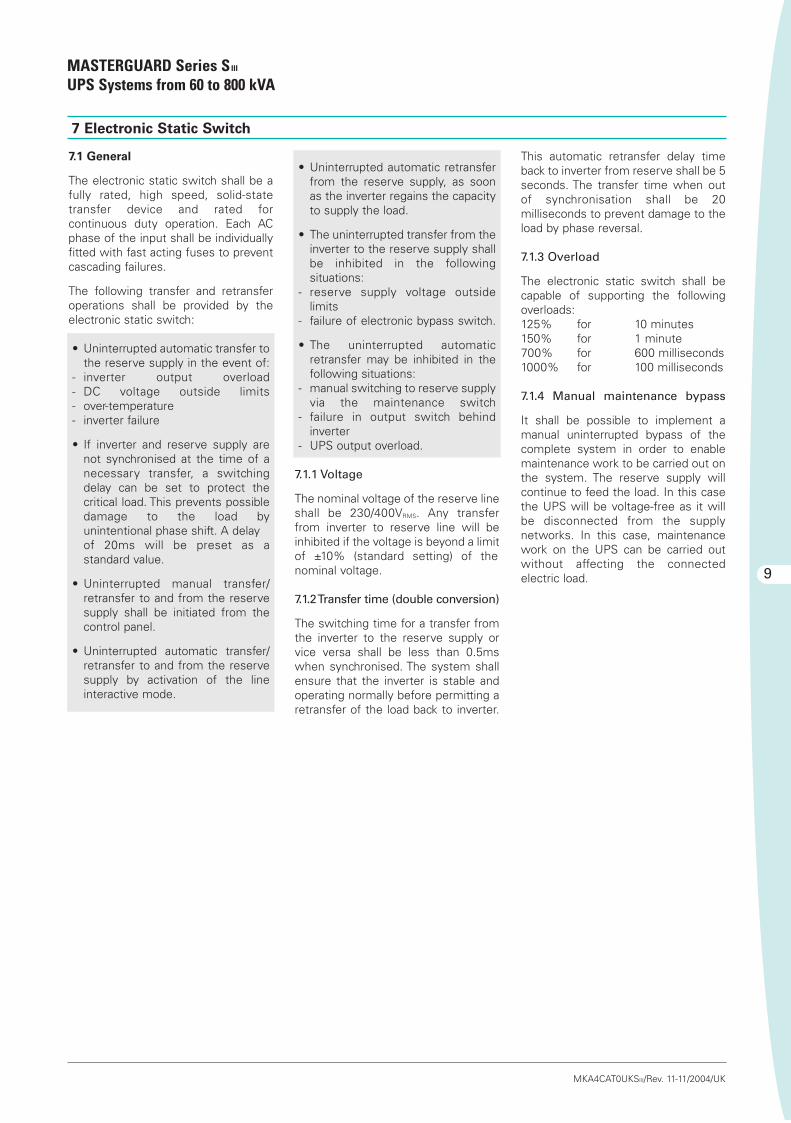
• Uninterrupted automatic retransferfrom the reserve supply, as soonas the inverter regains the capacityto supply the load.
• The uninterrupted transfer from theinverter to the reserve supply shallbe inhibited in the followingsituations:
- reserve supply voltage outside limits
- failure of electronic bypass switch.
• The uninterrupted automaticretransfer may be inhibited in thefollowing situations:
- manual switching to reserve supplyvia the maintenance switch
- failure in output switch behindinverter
- UPS output overload.
7.1.1 Voltage
The nominal voltage of the reserve lineshall be 230/400VRMS. Any transferfrom inverter to reserve line will beinhibited if the voltage is beyond a limitof ±10% (standard setting) of thenominal voltage.
7.1.2 Transfer time (double conversion)
The switching time for a transfer fromthe inverter to the reserve supply orvice versa shall be less than 0.5mswhen synchronised. The system shallensure that the inverter is stable andoperating normally before permitting aretransfer of the load back to inverter.
This automatic retransfer delay timeback to inverter from reserve shall be 5seconds. The transfer time when outof synchronisation shall be 20milliseconds to prevent damage to theload by phase reversal.
7.1.3 Overload
The electronic static switch shall becapable of supporting the followingoverloads:125% for 10 minutes150% for 1 minute700% for 600 milliseconds1000% for 100 milliseconds
7.1.4 Manual maintenance bypass
It shall be possible to implement amanual uninterrupted bypass of thecomplete system in order to enablemaintenance work to be carried out onthe system. The reserve supply willcontinue to feed the load. In this casethe UPS will be voltage-free as it willbe disconnected from the supplynetworks. In this case, maintenancework on the UPS can be carried outwithout affecting the connectedelectric load.
7.1 General
The electronic static switch shall be afully rated, high speed, solid-statetransfer device and rated forcontinuous duty operation. Each ACphase of the input shall be individuallyfitted with fast acting fuses to preventcascading failures.
The following transfer and retransferoperations shall be provided by theelectronic static switch:
• Uninterrupted automatic transfer tothe reserve supply in the event of:
- inverter output overload- DC voltage outside limits- over-temperature- inverter failure
• If inverter and reserve supply arenot synchronised at the time of anecessary transfer, a switchingdelay can be set to protect thecritical load. This prevents possibledamage to the load byunintentional phase shift. A delay of 20ms will be preset as astandard value.
• Uninterrupted manual transfer/retransfer to and from the reservesupply shall be initiated from thecontrol panel.
• Uninterrupted automatic transfer/retransfer to and from the reservesupply by activation of the lineinteractive mode.
Tecnico-SIII-MG 10-11-2004 8:22 Pagina 9

8 Monitoring and control, Interfaces
MASTERGUARD Series SIII
UPS Systems from 60 to 800 kVA
10
MKA4CAT0UKSIII/Rev. 11-11/2004/UK
8.1 General
The UPS shall incorporate the necessarycontrols, instruments and indicators toallow the operator to monitor the systemstatus and performance, and take actionwhere appropriate. Furthermore,interfaces allowing extended monitoringand control, in addition to servicefunctions shall be available. UPS ratedfrom 60kVA up to 500kVA feature amimic panel with graphical LCD displayas described in the section below, whileUPS rated 600kVA and 800kVA feature aspecific LCD and LED mixed mimic panel(for further details refer to the UserManuals pertaining to these models).
8.2 Mimic panel (60 to 500kVA)
The control panel of Series SIII includes aback-lit Liquid Crystal Display (LCD of
ON OFF
KEYBOARD
8.3 Start and Stop Inverter push
buttons
The Start and Stop push buttons areintegrated into the mimic panel board,and have the following predefinedfunctions:
The control shall incorporate a safetyfeature to prevent inadvertentoperation yet still allow for rapidshutdown in the event of anemergency. To stop the inverter theuser must press and hold the Stopbutton for two seconds. An audioalarm shall be activated during thisdelay time.
Start inverter operation
Stop inverter operation
eight lines x 12 characters, displayinggraphic diagrams and symbols) forcomplete UPS monitoring and control.Complete access to all LCD menus ispossible through navigation push buttonslocated below the screen. This navigationgroup includes two buttons - “up” and“down” - for menu scrolling and twosoftware-assigned push buttons: thefunction linked to these two buttons isdisplayed on the lower right and lower leftcorners of the LCD during navigation.
A single-line diagram of the UPS iscontinuously displayed on the defaultpage (for reference see figure 1). Themain functional blocks and power pathsof the UPS are displayed using simpleuniversal technical symbols, instantlycommunicating the overall status of theUPS. The same screen also permanentlydisplays the output load percentage
measurement, using three histograms(one for each output phase). In the caseof the UPS not in normal functioningmode, it is possible to access the“Warning and Alarm” summary pagedirectly from the default page. Warningsand alarms shall be identified by textstrings and codes. In battery operation,the display shall switch between warningcode and estimated backup time inminutes.
After 30 seconds of inactivity (i.e. withoutbuttons being pressed) the displayreverts to the default page.
The text displayed by the LCD shall beavailable in English, Italian, French,German, Spanish Portuguese, Turkishand Chinese, selectable by the user.
Graphical LCDscreen
Navigation buttons: left soft-key, up and down button, right soft-key
“Inverter On” push button
“Inverter Off” push button
“Alarm” LED
“System Normal” LED
Commands key lock
“Warning” LED
“Reset” push button(e.g. audible signalsilence for warning and alarm conditions)
Tecnico-SIII-MG 10-11-2004 8:22 Pagina 10
11
8 Monitoring and control, Interfaces
MASTERGUARD Series SIII
UPS Systems from 60 to 800 kVA
MKA4CAT0UKSIII/Rev. 11-11/2004/UK
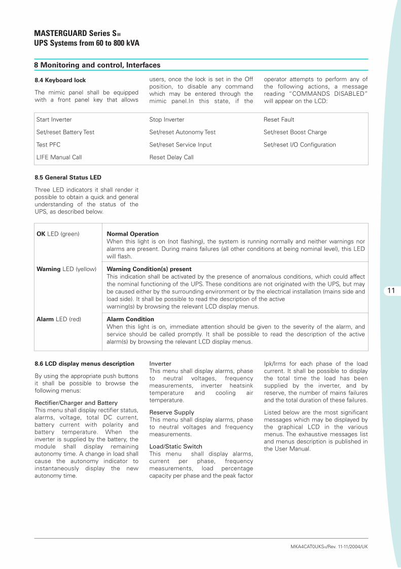
8.4 Keyboard lock
The mimic panel shall be equippedwith a front panel key that allows
Start Inverter Stop Inverter Reset Fault
Set/reset Battery Test Set/reset Autonomy Test Set/reset Boost Charge
Test PFC Set/reset Service Input Set/reset I/O Configuration
LIFE Manual Call Reset Delay Call
OK LED (green) Normal Operation
When this light is on (not flashing), the system is running normally and neither warnings nor alarms are present. During mains failures (all other conditions at being nominal level), this LEDwill flash.
Warning LED (yellow) Warning Condition(s) present
This indication shall be activated by the presence of anomalous conditions, which could affectthe nominal functioning of the UPS. These conditions are not originated with the UPS, but maybe caused either by the surrounding environment or by the electrical installation (mains side andload side). It shall be possible to read the description of the activewarning(s) by browsing the relevant LCD display menus.
Alarm LED (red) Alarm Condition
When this light is on, immediate attention should be given to the severity of the alarm, andservice should be called promptly. It shall be possible to read the description of the activealarm(s) by browsing the relevant LCD display menus.
8.6 LCD display menus description
By using the appropriate push buttonsit shall be possible to browse thefollowing menus:
Rectifier/Charger and BatteryThis menu shall display rectifier status,alarms, voltage, total DC current,battery current with polarity andbattery temperature. When theinverter is supplied by the battery, themodule shall display remainingautonomy time. A change in load shallcause the autonomy indicator toinstantaneously display the newautonomy time.
InverterThis menu shall display alarms, phaseto neutral voltages, frequencymeasurements, inverter heatsinktemperature and cooling airtemperature.
Reserve SupplyThis menu shall display alarms, phaseto neutral voltages and frequencymeasurements.
Load/Static SwitchThis menu shall display alarms,current per phase, frequencymeasurements, load percentagecapacity per phase and the peak factor
Ipk/Irms for each phase of the loadcurrent. It shall be possible to displaythe total time the load has beensupplied by the inverter, and byreserve, the number of mains failuresand the total duration of these failures.
Listed below are the most significantmessages which may be displayed bythe graphical LCD in the variousmenus. The exhaustive messages listand menus description is published inthe User Manual.
users, once the lock is set in the Offposition, to disable any commandwhich may be entered through themimic panel.In this state, if the
8.5 General Status LED
Three LED indicators it shall render itpossible to obtain a quick and generalunderstanding of the status of theUPS, as described below.
operator attempts to perform any ofthe following actions, a messagereading “COMMANDS DISABLED”will appear on the LCD:
Tecnico-SIII-MG 10-11-2004 8:22 Pagina 11
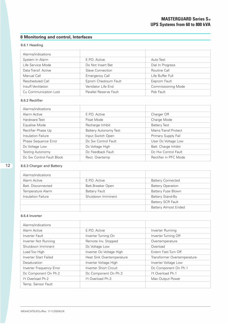
8.6.1 Heading
Alarms/indications
System In Alarm E.P.O. Active Auto Test
Life Service Mode Do Not Insert Bat Dial In Progress
Data Transf. Active Slave Connection Routine Call
Manual Call Emergency Call Life Buffer Full
Rescheduled Call Eprom Checksum Fault Eeprom Fault
Insuff.Ventilation Ventilator Life End Commissioning Mode
Cu Communication Lost Parallel Reserve Fault Pob Fault
8.6.2 Rectifier
Alarms/indications
Alarm Active E.P.O. Active Charger Off
Hardware Test Float Mode Charge Mode
Equalise Mode Recharge Inhibit Battery Test
Rectifier Phase Up Battery Autonomy Test Mains Transf.Protect
Insulation Failure Input Switch Open Primary Supply Fail
Phase Sequence Error Dc Sw Control Fault User Dc Voltage Low
Dc Voltage Low Dc Voltage High Batt. Charge Inhibit
Testing Autonomy Dc Feedback Fault Dc Hw Control Fault
Dc Sw Control Fault Block Rect. Overtemp Rectifier in PFC Mode
8.6.3 Charger and Battery
Alarms/indications
Alarm Active E.P.O. Active Battery Connected
Batt. Disconnected Batt.Breaker Open Battery Operation
Temperature Alarm Battery Fault Battery Fuse Blown
Insulation Failure Shutdown Imminent Battery Stand-By
Battery SCR Fault
Battery Almost Ended
8.6.4 Inverter
Alarms/indications
Alarm Active E.P.O. Active Inverter Running
Inverter Fault Inverter Turning On Inverter Turning Off
Inverter Not Running Remote Inv. Stopped Overtemperature
Shutdown Imminent Dc Voltage Low Overload
Load Too High Inverter Dc Voltage High Extern Fast Turn Off
Inverter Start Failed Heat Sink Overtemperature Transformer Overtemperature
Desaturation Inverter Voltage High Inverter Voltage Low
Inverter Frequency Error Inverter Short Circuit Dc Component On Ph.1
Dc Component On Ph.2 Dc Component On Ph.3 I3t Overload Ph.1
I2t Overload Ph.2 I2t Overload Ph.3 Max Output Power
Temp. Sensor Fault
8 Monitoring and control, Interfaces
MASTERGUARD Series SIII
UPS Systems from 60 to 800 kVA
12
MKA4CAT0UKSIII/Rev. 11-11/2004/UK
Tecnico-SIII-MG 10-11-2004 8:22 Pagina 12

8.6.5 Reserve
Alarms/indications
Alarm Active E.P.O. Active Reserve Valid
Reserve Not Valid Reserve Not Avail Res. Transf. Protect
Mains Synchro. Inhibit Reserve Supply Warning Backfeed Prot Active
Overload Phase 1, 2, 3 Not Ok Reserve Supply Fault
Reserve Hw Fault Bypass Sens. Fault
8.6.6 Load
Alarms/indications
Alarm Active E.P.O. Active Load On Reserve
Load On Inverter Load On Bypass Load Not Supplied
Insulation Failure System Output Sw Open Sys.Bypass Sw Closed
Output Switch Open Overload Load Too High
Bypass Switch Closed
13
8 Monitoring and control, Interfaces
MASTERGUARD Series SIII
UPS Systems from 60 to 800 kVA
MKA4CAT0UKSIII/Rev. 11-11/2004/UK
Tecnico-SIII-MG 10-11-2004 8:22 Pagina 13

8 Monitoring and control, Interfaces
MASTERGUARD Series SIII
UPS Systems from 60 to 800 kVA
14
MKA4CAT0UKSIII/Rev. 11-11/2004/UK
8.7 Interfaces
8.7.1 Slot card bay (available from 60to 500kVA)
Series SIII shall be equipped with two slotbays, available for communication cardoptions. One of the slots shall beequipped with the LIFE.net slot modem,fitted as standard (user removable).
The other slot shall be available for connectivity options. Please refer to MASTERGUARD ConnectivitySolutions for further details about theavailable slot expansion cards. If nocards are fitted into the slots, the DB9ports described in sections 8.7.3 and8.7.4 can be used for otherconnectivity applications.
8.7.2 Computer relay interface
Volt-free contacts shall beincorporated conforming to therequirements of IBM AS/400 and othercomputer types. This interface shall bevia a 9-pin D socket wired as follows:
Pin Signal Explanation
1 BYPASS ACTIVE Bypass mode: contact between pin 1 and pin 4 is closed
2 AC FAIL (NO) Mains failure: contact between pin 2 and pin 4 is closed
3 AC FAIL (NC) Mains failure: contact between pin 3 and pin 4 is open
4 SWITCH COM Common connection for all floating contacts
5 LOW BATTERY Just before end of discharge (in battery mode): contact between pin 5 and pin 4 is closed
6 UPS OFF If “mains failure” warning is present, application of 12 V across pin 6 and pin 7 (0 V)
shuts down the UPS
7 SIG GRD (0V) Reference potential for UPS shutdown
8 SUMMARY ALARM UPS fault, contact between pin 8 and pin 4 is closed
9 +12V Internal 12 V, 50 mA voltage source for UPS shutdown (pin 6)
Pin Signal Explanation
1 Earth Shield
2 TxD Send RS232
3 RxD Receive RS232
4 Not used
5 RS232 GND Signal ground for receive and send
6 Not used
7 RTS Clear to send RS232
8 Not used
9 Not used
The Floating contacts shall be rated at 24V, 1A.
This RS232 port cannot be used simultaneously with the corresponding slot bay as described in section 8.7.1
8.7.3 RS232C
Series SIII will be equipped with one D type connector with 9 pins for serial RS232C communication. The connector has thefollowing pin functions:
Pin Signal Explanation
1 Shield Cable shield
2 SST2_TRS232 Send RS232 (Tx)
3 SST2_RRS232 Receive RS232 (Rx)
4 Not used
5 Not used
6 Not used
7 M_BT Signal ground
8 Not used
9 Not Used
8.7.4 Combination interface
Series SIII shall be fitted with a slot modem for LIFE.net connection as standard. If this slot modem is removed, this portmay be used for other connectivity applications.
Tecnico-SIII-MG 10-11-2004 8:22 Pagina 14

15
8 Monitoring and control, Interfaces
MASTERGUARD Series SIII
UPS Systems from 60 to 800 kVA
MKA4CAT0UKSIII/Rev. 11-11/2004/UK
8.8 Available signalisations and
control signals
The UPS can handle up to 12Input/Output control signals (8 inputs,4 outputs) that can be programmed via
8.9 LIFE.net
In order to increase the overallreliability of the system, Series SIII willbe delivered with the LIFE.netcommunication kit, providingconnection to MASTERGUARD’sLIFE.net monitoring service.LIFE.net shall allow the remotemonitoring of the UPS throughtelephone lines or GSM link in order toensure the maximum reliability of theUPS throughout its operational life. Themonitoring shall be a real 24-hour, 365day service thanks to a unique featurethat allows trained Service Engineersto remain in constant electroniccontact with the service centre, andtherefore the UPS. The UPS shallautomatically dial-up the servicecentre at defined intervals to providedetailed information that shall beanalysed in order to predict near termproblems. In addition, it shall bepossible to control the UPS remotely.
The communication of UPS data to theMASTERGUARD LIFE CommandCentre shall take be transmitted viathe integrated modem at the followingintervals:
• ROUTINE: settable at intervals obetween five minutes and twodays (typically once a day)
• EMERGENCY: when a problemsoccurs or parameters are beyond tolerance limits
• MANUAL: following a requestfromthe command centre
During the call the command centreshall:
• Identify the UPS connected
• Request the data stored in the UPSmemory since the last connection
• Request real-time information fromthe UPS (selectable)
The service centre shall analysehistorical data and issue a regulardetailed report to the customerinforming him of the UPS operationalcondition and any critical states.The LIFE.net centre allows thepossibility of activating the LIFE-SMSdelivery system option, where thecustomer may receive SMSnotification which will be activated inthe event of one of the following:
• Mains power failure
• Mains power recovery
• Reserve line failure
• Load supplied by reserve.
Fan (On-Off) In Battery Compartment Battery Fuse Monitor
Battery Compartment Overheated Micro Switch UPS Doors
Backfeed Protection Generator On
Hydrogen Present Remote Inverter Stop
SBS Bypass Switch Closed Insufficient Ventilation
SBS Output Switch Open
the display and/or PPVIS for a wide setof functions. Emergency Power Off(EPO) is programmed as standard: thiscommand electronically shuts downthe rectifier, the inverter and thebypass switch. Listed below are the
most significant functions; theexhaustive list is published in the UserManual:
Tecnico-SIII-MG 10-11-2004 8:22 Pagina 15

9 Mechanical data
MASTERGUARD Series SIII
UPS Systems from 60 to 800 kVA
16
10 Environmental conditions
MKA4CAT0UKSIII/Rev. 11-11/2004/UK
The enclosure shall be installed with atleast 400 mm of free space betweenthe device and roof of the enclosure inorder to allow cooling air to exitunhindered.
9.3 Cable entry
Cable entry shall be from the bottomor bottom-side of the cabinet. Topcable entry shall be available as anoption.
9.4 Enclosure design
All enclosure surfaces of the enclosureshall be finished with anelectrostatically applied epoxy coat.The coating shall have a thickness of at
least 60 microns. Standard colour ofthe enclosure shall be RAL 7035 (lightgrey).
9.5 Access to integrated subassem-
blies
All internal subassemblies shall beaccessible for typical and mostfrequent maintenance from the frontof the unit via hinged doors. Rearaccess shall not be required forinstallation or servicing. The UPS shallbe forkliftable from the front after theremoval of the bottom trim panels.
9.1 Enclosure
The UPS shall be housed in a space-saving modular enclosure with frontdoors and removable panels(protection as standard to IP 20). Theenclosure shall be made of zinteccoated sheet steel. The doors shall belockable.
9.2 Ventilation
Forced redundant air cooling willensure that all the components areoperated within their specification.Airflow shall be controlled according todemand. The cooling air entry shall bein the base and the air exit at the top ofthe device.
The UPS shall be capable ofwithstanding any combination of theenvironmental conditions listed below.It shall operate without mechanical orelectrical damage or degradation ofoperating characteristics.
10.1 Ambient temperature
0° to 40°CMaximum average daily temperature(24 hr) 35°CMaximum temperature (8 hr) 40°C
10.2 Relative humidity
Up to 90% (non condensing) fortemperature of 20°C.
10.3 Altitude
The maximum altitude withoutderating shall be 1000 metres abovesea level or 1500 metres at 25°C. Thederating shall be 1.2% for every 100metres above 1000 metres.
Tecnico-SIII-MG 10-11-2004 8:22 Pagina 16

UPS Unit Rating 60 80 100 120 160 200
11.1 Rectifier input
Nominal input voltage (V) 400 3Ph (380 – 415 selectable)
Tolerance on voltage assuming float @ 2.27V per cell (%)(1) ±15
Min. input voltage without battery discharge (%)(1) -25
Nominal frequency (Hz) 50/60 (selectable)
Tolerance on frequency (%) ±5
Maximum input power @400V, Recharge Mode (kVA) 85 111 139 168 222 278
Power factor @400V, PFC Mode (±0,02) >0.92
Power factor @400V, Float Mode >0.8
Input current distortion @ maximum input power (%) <30
Walk in/Soft start (programmable) (seconds) 10 (1-90)
Rectifier Hold-Off (programmable) (seconds) 1 (1-180)
Inrush current / Imax input ratio(8) <1
Efficiency of rectifier in float(2): Half load % 98.9Full load % 98.9
11.2 Rectifier output
Battery nominal voltage @ recommended number of cells, see 11.8 (V) 396
Output voltage: Float for SLA @ 20°C (V) 449Recharge *(V) 475
*Only for wet stationary lead batteries
Battery float voltage temperature compensation (direct sensing) -0.11% per °C
Current ripple into battery for a 10 min autonomy as per VDE0510(3) <0.05C10
Voltage stability in steady state condition for 100% load variations or allowed input parameters variations (%) <1
Voltage ripple in float condition (%) <2
DC current supplied to inverter in float (A) 115 153 190 229 303 379
Battery recharge current setting range (A) 5-25 5-25 10-40 10-40 15-65 15-65
Maximum DC current (A) 150 195 245 295 390 490
11.3 Inverter input
Nominal voltage on float (V) 449
DC voltage range (V) 326-540
DC current when inverter at full load (0.8PF) and battery at end of discharge (A) 158 210 260 315 417 521
17
MASTERGUARD Series SIII
UPS Systems from 60 to 800 kVA
MKA4CAT0UKSIII/Rev. 11-11/2004/UK
11 Technical data (60 to 200 kVA)
Tecnico-SIII-MG 10-11-2004 8:22 Pagina 17

MASTERGUARD Series SIII
UPS Systems from 60 to 800 kVA
UPS Unit Rating 60 80 100 120 160 200
11.4 Inverter output
Nominal apparent power @ PF 0.8 lagging 40°C (kVA) 60 80 100 120 160 200
Nominal active power (kW) 48 64 80 96 128 160
Nominal output current (A) 87 116 145 174 232 290
Nominal apparent and active power @ PF >0.8, lagging or leading, 40°C See note (7)
Overload at nominal output voltage and 0.8 PF for 10 min (%) 125
Overload at nominal output voltage and 0.8 PF for 1 min (%)(6) 150
Short circuit current capacity for 5 seconds (10ms) (%) 150 (200)
Nominal output voltage (V) 400 (380/415 selectable) 3Ph + n
Nominal frequency (Hz) 50/60 (selectable)
Voltage stability in steady state condition for input DC variations and 100% load variations (%) ±1
Voltage stability in dynamic condition for 100% nominal load step variations or DC input variations (%) Complies with IEC/EN 62040-3, Class 1
Voltage stability in steady state for 100% unbalanced loads (0, 0, 100) (%) ±3
Output frequency stability In synchro with the mains (%) ±0.75 (1.5, 2.5, 6 selectable)With internal quartz oscillator (%) ±0.05
Frequency slew rate (Hz/sec) <1
Output voltage distortion with 100% linear load (%) <3
Output voltage distortion @ reference non linear load as for IEC/EN 62040-3 (%) <5
Load crest factor without derating (Ipk/Irms) 3:1
Phase angle precision with balanced loads (degrees) <±1
Phase angle precision with 100% unbalanced loads (degrees) <±2
DC/AC efficiency(2): Half load 92.0 92.5 93.0 93.0 93.5 93.5Full load 93.0 93.0 93.5 93.5 94.0 94.0
Neutral conductor sizing see Chapter 6.5
Output power upgradability with temperature: At 25°C (%) 110At 30°C (%) 105At 40°C (%) 100
11 Technical data (60 to 200 kVA)
18
MKA4CAT0UKSIII/Rev. 11-11/2004/UK
Tecnico-SIII-MG 10-11-2004 8:22 Pagina 18

MASTERGUARD Series SIII
UPS Systems from 60 to 800 kVA
UPS Unit Rating 60 80 100 120 160 200
11.5 Reserve static switch
Nominal voltage (V) 400 (380/415 selectable) 3Ph + n
Nominal frequency (Hz) 50/60 (selectable)
Frequency range (%) ±0.75 (1.5, 2.5, 6.0 selectable)
Voltage range (%) ±10
Maximum operating voltage (V) 480/277
Maximum overload capacity For 10 minutes (%) 125For 1 minute (%) 150For 600 milliseconds (%) 700For 100 milliseconds (%) 1000
SCR I2t @ Tvj=130°C; 8.3-10ms (A2s) 80k 80k 80k 80k 320k 320k
ITSM @ Tvj=130°C; 10ms (A) 4k 4k 4k 4k 8k 8k
Fuse Rating (Vac/A) 660/250 660/250 660/250 660/350 660/500 660/500
Pre-arching I2t (A2s) 4.4k 4.4k 4.4k 10.5k 23.8k 23.8k
I2t @ 400Vac (A2s) 31.5k 31.5k 31.5k 33.5k 105k 105k
Transfer time when in synchro (double conversion)Inverter to reserve (ms) <0.5Reserve to inverter (ms) <0.5
Transfer time without synchro (ms) <20
Retransfer delay (sec) <5
11.6 System data
Maximum input power @400V, Recharge Mode (kVA) 85 111 139 168 222 278
Heat dissipation: PFC Mode (kW) 4.2 5.6 6.5 7.8 9.6 12.0Rapid recharge (kW) 4.4 5.8 6.8 8.1 10.0 12.6Digital interactive (kW) 1.5 2 2.5 3 4 5
AC/AC efficiency(2): Half load double conv. (%) 91.0 91.5 92.0 92.0 92.5 92.5Full load double conv. (%) 92.0 92.0 92.5 92.5 93.0 93.0Digital Interactive (%) 97 97 97 97 97 97
Noise @ 1 metre as per ISO 3746 (dBA ± 2dBA) 62 62 62 64 65 65
Protection degree with open doors IP20
Mechanical dimensions: Height (mm) 1780Width (mm) 820 820 1020 1020 1420 1420Depth (mm)(4) 858
No of cabinet 1
Colour Frame (RAL scale) 7035Bottom panel (RAL scale) 7035
Weight (kg) 660 660 720 875 1290 1290
Floor area (m2) 0.68 0.68 0.85 0.85 1.18 1.18
Floor loading (kg/m2) 980 980 850 1030 1095 1095
Cable entry Bottom/Side
Access Front
Cooling Forced Ventilation
11 Technical data (60 to 200 kVA)
19
MKA4CAT0UKSIII/Rev. 11-11/2004/UK
Tecnico-SIII-MG 10-11-2004 8:22 Pagina 19
MASTERGUARD Series SIII
UPS Systems from 60 to 800 kVA
20
MKA4CAT0UKSIII/Rev. 11-11/2004/UK
UPS Unit Rating 60 80 100 120 160 200
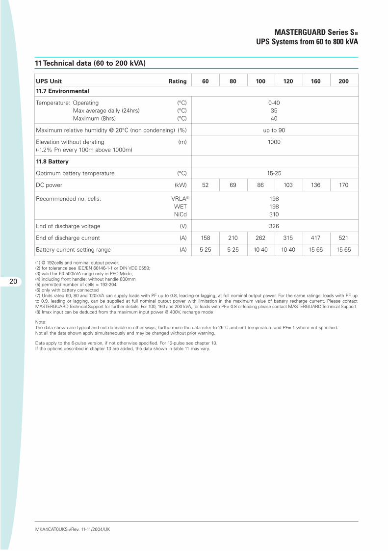
11.7 Environmental
Temperature: Operating (°C) 0-40Max average daily (24hrs) (°C) 35Maximum (8hrs) (°C) 40
Maximum relative humidity @ 20°C (non condensing) (%) up to 90
Elevation without derating (m) 1000 (-1.2% Pn every 100m above 1000m)
11.8 Battery
Optimum battery temperature (°C) 15-25
DC power (kW) 52 69 86 103 136 170
Recommended no. cells: VRLA(5) 198WET 198NiCd 310
End of discharge voltage (V) 326
End of discharge current (A) 158 210 262 315 417 521
Battery current setting range (A) 5-25 5-25 10-40 10-40 15-65 15-65
11 Technical data (60 to 200 kVA)
(1) @ 192cells and nominal output power;(2) for tolerance see IEC/EN 60146-1-1 or DIN VDE 0558;(3) valid for 60-500kVA range only in PFC Mode;(4) including front handle; without handle 830mm(5) permitted number of cells = 192-204(6) only with battery connected(7) Units rated 60, 80 and 120kVA can supply loads with PF up to 0.8, leading or lagging, at full nominal output power. For the same ratings, loads with PF upto 0.9, leading or lagging, can be supplied at full nominal output power with limitation in the maximum value of battery recharge current. Please contact MASTERGUARDTechnical Support for further details. For 100, 160 and 200 kVA, for loads with PF> 0.8 or leading please contact MASTERGUARD Technical Support.(8) Imax input can be deduced from the maximum input power @ 400V, recharge mode
Note:The data shown are typical and not definable in other ways; furthermore the data refer to 25°C ambient temperature and PF= 1 where not specified.Not all the data shown apply simultaneously and may be changed without prior warning.
Data apply to the 6-pulse version, if not otherwise specified. For 12-pulse see chapter 13.If the options described in chapter 13 are added, the data shown in table 11 may vary.
Tecnico-SIII-MG 10-11-2004 8:22 Pagina 20

21
MASTERGUARD Series SIII
UPS Systems from 60 to 800 kVA
MKA4CAT0UKSIII/Rev. 11-11/2004/UK
UPS Unit Rating 250 300 400 500 600 800
12.1 Rectifier input
Nominal input voltage (V) 400 3Ph (380 – 415 selectable)
Tolerance on voltage assuming float @ 2.27V per cell (%)(1) +15/-12
Min. input voltage without battery discharge (%)(1) -21
Nominal frequency (Hz) 50/60 (selectable)
Tolerance on frequency (%) ±5
Maximum input power @400V, Recharge Mode (kVA) 351 421 562 702 842 1123
Power factor @400V, PFC Mode (±0,02) >0.9 >0.9 >0.9 >0.9 n.a. n.a.
Power factor @400V, Float Mode >0.8
Input current distortion @ maximum input power (%) <5
Walk in/Soft start (programmable) (seconds) 10 (1-90)
Rectifier Hold-Off (programmable) (seconds) 1 (1-180)
Inrush current / Imax input ratio(8) <4
Efficiency of rectifier in float(2): Half load % 97.9 97.9 97.9 97.9 97.0 97.0Full load % 97.9 97.9 97.9 97.9 97.4 97.4
12.2 Rectifier output
Battery nominal voltage @ recommended number of cells, see 12.8 (V) 480
Output voltage: Float for SLA @ 20°C (V) 545Recharge (V)* 576
*Only for wet stationary lead batteries
Battery float voltage temperature compensation (direct sensing) -0.11% per °C
Current ripple into battery for a 10 min autonomy as per VDE0510(3) <0.05C10
Voltage stability in steady state condition for 100% load variations or allowed input parameters variations (%) <1
Voltage ripple in float condition (%) <2
DC current supplied to inverter in float (A) 391 466 622 777 932 1243
Battery recharge current setting range (A) 15-80 15-80 20-110 25-135 25-160 30-210
Maximum DC current (A) 500 600 800 1000 1200 1600
12.3 Inverter input
Nominal voltage on float (V) 545
DC voltage range (V) 396-600
DC current when inverter at full load (0.8PF) and battery at end of discharge (A) 538 645 855 1069 1283 1710
12 Technical data (250 to 800 kVA)
Tecnico-SIII-MG 10-11-2004 8:22 Pagina 21

UPS Unit Rating 250 300 400 500 600 800
12.4 Inverter output
Nominal apparent power @ PF 0.8, lagging 40°C (kVA) 250 300 400 500 600 800
Nominal active power (kW) 200 240 320 400 480 640
Nominal output current (A) 362 435 580 725 870 1159
Nominal apparent and active power @ PF >0.8, lagging or leading, 40°C See note (7)
Overload at nominal output voltage and 0.8 PF for 10 min (%) 125
Overload at nominal output voltage and 0.8 PF for 1 min (%)(6) 150
Short circuit current capacity for 5 seconds (10ms) (%) 150 (200)
Nominal output voltage (V) 400 (380/415 selectable) 3Ph + n
Nominal frequency (Hz) 50/60 (selectable)
Voltage stability in steady state condition for input DC variations and 100% load variations (%) ±1
Voltage stability in dynamic condition for 100% nominal load step variations or DC input variations (%) Complies with IEC/EN 62040-3, Class 1
Voltage stability in steady state for 100% unbalanced loads (0, 0, 100) (%) ±3
Output frequency stability In synchro with the mains (%) ±0.75 (1.5, 2.5, 6 selectable)With internal quartz oscillator (%) ±0.05
Frequency slew rate (Hz/sec) <1
Output voltage distortion with 100% linear load (%) <3
Output voltage distortion @ reference non linear load as for IEC/EN 62040-3 (%) <5
Load crest factor without derating (Ipk/Irms) 3:1
Phase angle precision with balanced loads (degrees) <±1
Phase angle precision with 100% unbalanced loads (degrees) <±2
DC/AC efficiency(2): Half load 93.5 94.0 94.0 94.0 94.0 94.0Full load 94.0 94.5 94.5 94.5 94.5 94.5
Neutral conductor sizing see Chapter 6.5
Output power upgradability with temperature: At 25°C (%) 110
At 30°C (%) 105At 40°C (%) 100
12 Technical data (250 to 800 kVA)
MASTERGUARD Series SIII
UPS Systems from 60 to 800 kVA
22
MKA4CAT0UKSIII/Rev. 11-11/2004/UK
Tecnico-SIII-MG 10-11-2004 8:22 Pagina 22

UPS Unit Rating 250 300 400 500 600 800
12.5 Reserve static switch
Nominal voltage (V) 400 (380/415 selectable) 3Ph + n
Nominal frequency (Hz) 50/60 (selectable)
Frequency range (%) ±0.75 (1.5, 2.5, 6.0 selectable)
Voltage range (%) ±10
Maximum operating voltage (V) 480/277
Maximum overload capacityFor 10 minutes (%) 125For 1 minute (%) 150For 600 milliseconds (%) 700For 100 milliseconds (%) 1000
SCR I2t @ Tvj=130°C; 8.3-10ms (A2s) 320k 320k 1125k 1125k 1125k 4500kITSM @ Tvj=130°C; 10ms (A) 8k 8k 15k 15k 15k 30k
Fuse Rating (Vac/A) 660/500 660/500 660/1000 660/1000 660/1000 660/1600Pre-arching I2t (A2s) 23.8k 23.8k 142k 142k 142k 308kI2t @ 400Vac (A2s) 105k 105k 630k 630k 630k 1332k
Transfer time when in synchro (double conversion): Inverter to reserve (ms) <0.5
Reserve to inverter (ms) <0.5
Transfer time without synchro (ms) <20
Retransfer delay (sec) 5
12.6 System data
Maximum input power @400V, Recharge Mode (kVA) 356 421 562 702 842 1123
Heat dissipation: PFC Mode (kW) 17.4 19.5 25.9 32.4 n.a.Float Mode (kW) 41.7 55.7Rapid recharge (kW) 18.7 21.1 27.9 34.9 45.6 60.8Digital interactive (kW) 6.2 7.4 10 12.4 14.8 19.8
AC/AC efficiency(2): Half load double conv. (%) 91.5 92.0 92.0 92.0 91.2 91.2Full load double conv. (%) 92.0 92.5 92.5 92.5 92.0 92.0Digital Interactive (%) 97.0
Noise @ 1 metre as per ISO 3746 (dBA ± 2dBA) 68 68 70 72 75 75
Protection degree with open doors IP20
Mechanical dimensions: Height (mm) 1780 1780 1780 1780 1780 1980Width (mm) 1620 1620 1620 2020 3860 3860Depth (mm)(4) 858 858 858 858 1058 1058
No. of cabinets 1 1 1 1 3 3
Colour Frame (RAL scale) 7035Bottom panel (RAL scale) 7035
Weight (kg) 1880 1880 2080 2580 3960 4820
Floor area (m2) 1.35 1.35 1.35 1.68 3.98 3.98
Floor loading (kg/m2) 1390 1390 1540 1535 1000 1210
Cable entry Bottom/Side
Access Front
Cooling Forced Ventilation
23
12 Technical data (250 to 800 kVA)
MASTERGUARD Series SIII
UPS Systems from 60 to 800 kVA
MKA4CAT0UKSIII/Rev. 11-11/2004/UK
Tecnico-SIII-MG 10-11-2004 8:22 Pagina 23

12 Technical data (250 to 800 kVA)
MASTERGUARD Series SIII
UPS Systems from 60 to 800 kVA
24
MKA4CAT0UKSIII/Rev. 11-11/2004/UK
UPS Unit Rating 250 300 400 500 600 800
12.7 Environmental
Temperature: Operating (°C) 0-40Max average daily (24hrs) (°C) 35Maximum (8hrs) (°C) 40
Maximum relative humidity @ 20°C (non condensing) (%) up to 90
Elevation without derating (m) (-1.2% Pn every 100 m above 1000 m) 1000
12.8 Battery
Optimum battery temperature (°C) 15-25
DC power (kW) 213 254 339 423 508 677
Recommended no. cells: VRLA(5) 240WET 240NiCd 375
End of discharge voltage (V) 396
End of discharge current (A) 538 645 855 1069 1283 1710
Battery current setting range (A) 15-80 15-80 20-110 25-135 25-160 30-120
(1) @ 234 cells and nominal output power;(2) for tolerance see IEC/EN 60146-1-1or DIN VDE 0558;(3) valid for 60-500kVA range only in PFC Mode;(4) including front handle; without handle 830/1030 mm(5) permitted number of cells = 234-246(6) only with battery connected(7) Units rated 250, 300, 400 and 500 kVA can supply loads with PF up to 0.8, leading or lagging, at full nominal output power. For the same ratings, loads withPF up to 0.9, leading or lagging, can be supplied at full nominal output power with limitation in the maximum value of battery recharge current. Please contactMASTERGUARD Technical Support for further details. For 800 kVA and 600 kVA for loads with PF> 0.8 or leading please contact MASTERGUARD Technical Support.(8) Imax input can be deduced from the maximum input power @400V, recharge mode.
Note:The data shown are typical and not definable in other ways; furthermore the data refer to 25°C ambient temperature and PF= 1 where not specified.Not all the data shown apply simultaneously and may be changed without prior warning.If the options described in chapter 13 are added, the data shown in table 12 may vary.
Tecnico-SIII-MG 10-11-2004 8:22 Pagina 24

filter mounted within the 6 pulserectifier UPS version (available only upto 200kVA) shall limit the THDi to lessthan 7%. The input power factor willdepend on the output load fraction.
6 pulse 6 pulse +
7% filter
5th harmonic 29 % 4 %
7th harmonic 5 % 3 %
11th harmonic 7 % 3 %
13th harmonic 1 % 1 %
17th harmonic 3 % 2 %
19th harmonic 1 % 1 %
Total THDi 30 % 7 %
13.12 12-pulse rectifierr @ THDi < 5%
(optional for 60 – 200kVA, standard
from 250kVA).
This version shall consist of two 6pulse rectifiers phase shifted by 30degrees; with an additional inductivereactance on both rectifier branches.This shall attenuate the 5th, 7th, I7thand I9th harmonics in order to achievea THDi of approximately 5%. The 12-pulse rectifier shall be housed withinthe UPS cubicle. When this option isfitted (for 60 – 200kVA range), theoverall AC/AC efficiency shall bereduced by 2.5%, the generatedacoustic noise increased by I dBA, thepower factor in PFC Mode reduced to0,90±0,02 and the input voltagetolerance is –11% @ 192 cells. The inputinrush current shall be limited to <4Imax input.
12 pulse +
5% filter
5th harmonic 1 %
7th harmonic 1 %
11th harmonic 4 %
13th harmonic 2 %
17th harmonic -
19th harmonic -
Total THDi 5 %
13.13 Multiple Bus Synchronization
Module (MBSM)
The synchronisation kit shall be usedto synchronise UPS systems in orderto ensure perfect operation withCROSS system static switches. Toachieve this, all UPS must beinterconnected. The MBSM box allowsfor communication between up to sixUPS. For more than six UPS cascadedMBSM boxes should be used.
25
13 Options
MASTERGUARD Series SIII
UPS Systems from 60 to 800 kVA
MKA4CAT0UKSIII/Rev. 11-11/2004/UK
It shall also be possible to monitor theinsulation resistance when the rectifierisolation is not present by taking themeasurement when the input rectifierswitch is open or the rectifier isswitched off.
13.7 Battery Management Modules
(only upon request)
With measuring modules connectedto the battery blocks, enhancedbattery management shall be possibleoffering the following features:
• Measurement of the condition ofeach individual battery block bymeans of separate batterymeasuring modules (BMM)
• Analysis of each battery block withmeasurement of the minimum andmaximum voltage values.
13.8 Isolation transformer
This option shall be a double woundtransformer housed in a matchingcubicle. The transformer shallincorporate an electrostatic screen asstandard. The option shall be used toisolate the rectifier/output/reservefrom the mains AC input. Starting from250 kVA cable entry shall be from thetop; smaller versions shall have entryfrom the bottom. The transformercabinets do not include switchingdevices. This option may significantlyaffect the reserve line inrush current,influencing the sizing of the upstreamprotection devices. For furtherinformation please contact theMASTERGUARD Technical Support;optional low inrush current isolationtransformers may be provided onrequest.
13.9 Top cable entry
This option shall allow power cableentry from the top of the UPS.
13.10 Dust filters
This option shall improve theprotection degree of the air entrancefrom IP20 to lP40 for specificapplications such as a dustyenvironment. The filter shall be housedin the UPS cubicle (IP20).
13.11 Input harmonic filters for 6
pulse versions (only upon request)
The input current harmonic distortion
Where options described in thischapter are added to the UPS, the datapresented in the standard technicaldata tables may vary. Some optionsmay not be available contemporarily onthe same UPS.
13.1 Parallel configurations
See chapter 14.
13.2 Remote alarm unit
A remote alarm panel shall be availableto display important individualmessages from the UPS.Upon request, it shall be possible todisplay up to four UPS systems. Thelength of the connecting cable mustnot exceed 300 m.
13.3 External battery circuit breaker
This option shall include a fully ratedcircuit breaker and an additionalauxiliary contact for monitoring itsposition. The circuit breaker shall behoused in a wall-mounted box anddesigned for battery systems whichare mounted on racks. Furthermore,the circuit breaker shall serve as asafety element for the cross section ofthe power cable between UPS and theremotely placed battery system.
13.4 Backfeed protection (only upon
request)
This option shall prevent any potentialrisk from electric shock on the UPSinput AC terminals in the event offailure by the reserve static switchSCR. The option shall include a contactwhich activates an external isolatingdevice such as an electromechanicalrelay. The external isolating device is notincluded in the option. Alternatively, itshall be possible to incorporate thisdevice inside the UPS cabinet.
13.5 Additional RFI filters (only upon
request)
Feed-through RFl filters shall beavailable housed in a matching cubicle.They allow a reduction of theconducted emissions up to the Class Bof standard EN50091-2.
13.6 Battery leakage alarm
ln conjunction with the rectifierisolation transformer option, thebattery leakage alarm shall monitor theinsulation resistance on the DC bus.
Tecnico-SIII-MG 10-11-2004 8:22 Pagina 25

13 Options
MASTERGUARD Series SIII
UPS Systems from 60 to 800 kVA
26
MKA4CAT0UKSIII/Rev. 11-11/2004/UK
13.17 Customer interface board
It shall be possible to increase thenumber of input/outputs described insection 8.8 by the adding of anadditional board. These input/outputscan be used to monitor smoke, fireand water detectors, as specified bythe user. Each board shall comprise:
• Four digital inputs (from voltagefree contacts)
• Two outputs - voltage free contacts(1A 30V AC/DC)
13.18 Telephone switch for LIFE.net
The installation of the telephoneswitch for LIFE.net shall allow the userto use a telephone line normallyreserved for other purposes (e.g. faxor telephone).
13.19 MopUPS Shutdown and
monitoring software
The main function of MopUPSsoftware shall be the safe shutdown ofthe operating system in the event of apower failure. Other functions include:
1. Automatic communications for events;e-mail, SMS, etc.
2.Saving to file of event log and statusinformation
3.Viewing and monitoring of UPS inrealtime
4.Programmed system shutdown5.Remote monitoring of UPS
connected to network server usingNamed Pipes or TCP/IP
13.20 ManageUPS adapter
This option shall include a completepackage (including slot card adapter) toensure monitoring and control of thenetworked UPS through TCP/IPprotocol. The adapter permits:
• UPS monitoring from NMS viaSNMP
• UPS monitoring from PC via a Webbrowser.
• Dispatch of e-mail messages onoccurrence of events
ManageUPS, in conjunction withMopUPS, shall also permit safeshutdown of the operating systems.
13.21 PPVIS surveys Monitoring
Software
In addition to full monitoring capability,this powerful software connectivitytool allows complete access to theUPS configuration parameters.Therefore the user must attend aspecialist training session withMASTERGUARD Service Engineersbefore being granted access to PPVis.
The survey images as displayed belowsupply the user with essentialinformation on the connected UPS:
State indication - power flux survey
• Current state of components (UPS)• Display of output voltage, UPS
performance and load currents• Number of power failures• Battery cell voltage• Available backup time
The oscilloscope - measuring ofnetwork or load conditions
• Dual-carrier measurement of thecurves of input, output voltages orcurrents.
• Flexible definable trigger conditionscapable of being coupled with themost varied events, such as whena mains failure occurs
13.14 Empty battery cubicle
Matching empty battery cubicles shallbe available including:
• Cubicle
• Disconnecting means
• Fuses
• Safety screen
• Connection terminals
• UPS/battery connection cables (foradjacent installations)
Three cubicle sizes shall be available:
Width Depth Height Weight(mm) (mm) (mm) (kg)
Type A 820 858* 1780 220
Type B 1020 858* 1780 250
Type C 1020 1058* 1980 350
* including front handle; withouthandle 830/1030 mm
13.15 Empty options cubicle
A matching cubicle shall be availablefor customised applications such as:
• Input/Output voltage matchingtransformers
• Customised distribution boards
• Customised applications.
The options cubicle shall be availablein four sizes:
Width Depth Height Weight(mm) (mm) (mm) (kg)
Type A 820 858* 1780 180
Type B 1020 858* 1780 200
Type C 1420 858* 1780 250
Type D 1020 1058* 1980 300
* including front handle; withouthandle 830/1030 mm
13.16 Use as Frequency Converter
Series SIII may be programmed for useas a frequency converter (50Hz in –60Hz out or 60Hz in – 50Hz out) foroperations without a battery bankconnected. In this operational mode,the data shown in tables 11 and 12 mayvary (e.g. output overload capability).Please contact MASTERGUARDTechnical Support for details.
Tecnico-SIII-MG 10-11-2004 8:22 Pagina 26

Compatibility Table
LIFE.net MopUPS ManageUPS PPVIS
LIFE.net No Yes Yes
MopUPS No Yes Yes*
ManageUPS Yes Yes Yes
PPVIS Yes Yes* Yes
* use LIFE.net port for MopUPS
27
13 Options
MASTERGUARD Series SIII
UPS Systems from 60 to 800 kVA
14 Parallel configurations
MKA4CAT0UKSIII/Rev. 11-11/2004/UK
Battery display - Recognition ofparasitic effects in the early stages(optional for single blocks)
• Measuring of the condition of eachindividual battery block shall bemonitorable by means of separatebattery measuring modules (BMM)
• By clicking of mouse the user mayanalyse each battery block withmeasurements of the minimumand maximum voltage values.
The Series SIII series of uninterruptiblepower supply systems shall beconnectable in parallel for multi-module configurations between unitsof the same rating. The maximumnumber of UPS in parallelconfiguration shall be eight (seven forsystems with a centralised staticswitch and for HFC systems).The parallel connection of UPS shallincrease reliability and power.
Reliability.If the installation requires more thanone unit in redundant configuration thepower of each UPS should not belower than Ptot/(N-1) where:
Ptot = Total load powerN = Number of UPS units in parallel1 = Minimum coefficient of
redundancy
Under normal operating conditions,the power delivered to the load shallbe shared between the number ofUPS units connected to the parallelbus. In case of overload the configurationmay deliver Pov x N without transferringthe load onto the reserve, where:
Pov = Max overload power of asingle UPS
N = Number of UPS units inparallel.
In the event of failure by one of theUPS units, the faulty unit shall bedisconnected from the parallel bus andthe load shall be supplied from theremaining units without any break insupply continuity.
Power.It shall be possible to increase thepower of the system using a non-redundant parallel configuration(redundancy coefficient = 0). In thiscase all connected UPS units shalldeliver the rated power, and in theevent of a unit failure or overload thesystem shall transfer the load to reserve.
A maximum of eight UPS may beconnected in parallel. There shall bethree alternative paralleling methods:modular parallel, centralised parallelwith COC and high fault clearance(HFC) parallel mode.
Performance features.The performance features of theparallel system are related to the UPSsystems employed. The distribution ofthe load is divided equally between theindividual UPS systems.
13.22 J-Bus protocol
An optional kit shall ensure thecompatibility of Series SIII with the J-Bus protocol on RS485 port.
13.23 Profi Bus protocol
By installing a Profibus-DP connectionSeries SIII shall be linked up to higherlevel automatic systems. The Profibus–DP bus system enables very fastcyclical data exchange between higher-
level systems such as Simatic S5, S7,Symadyn D, PC/PG and field units. Thefollowing information shall betransmitted by Series SIII:
• Status of the unit
• Alarm information, information onfaults
• Voltage levels at UPS output
• Control information
Tecnico-SIII-MG 10-11-2004 8:22 Pagina 27

14 Parallel configurations
MASTERGUARD Series SIII
UPS Systems from 60 to 800 kVA
28
MKA4CAT0UKSIII/Rev. 11-11/2004/UK
14.1 Modular
The UPS systems of the Series SIII
series shall be capable of operating inparallel modular configuration. For thispurpose UPS systems of the samerating shall be connected in parallel toform multi-module configurations.The parallel connection of UPS shall either improve reliability, the total output power, or both. Provided Series SIII is supplied with theparallel kit option, up to eight equalUPS units can be operated in parallelfor power upgrade or increase ofredundancy. This option can also beadded on at a later date. The optionshall consist of one subassembly POB (Parallel Operation Board) and 25 pole, screened data lines to the neighbouring UPS modules. A multi-module system shall becontrolled and monitored automaticallyby controlling the individual UPSsystems. The reserve lines andinverters included in each UPS sharethe load. The load sharing among theUPS parallel system (“load oninverter” mode) shall be achieved witha tolerance of less than 5% at anysystem load fraction (0 - 100%).
14.1.1 System bypass switches
A system bypass switch shall beavailable as an option for the modularparallel configuration. For parallelsystems including more than two UPS,a system bypass switch must beprovided within the installation,including two power disconnectswitches. The ratings available shall be:
Height Weight Depth Weight(mm) (mm) (mm) (kg)
400 A 1780 620 858* 300
800 A 1780 620 858* 400
1600 A 1780 1020 858* 500
2500 A 1780 1020 858* 600
* including front handle; withouthandle 830 mm
14.2 Centralised parallel with COC
The centralised paralleling architectureenables UPS with inhibited bypass tobe connected in parallel. Hereby thereserve supply to the loads works withone central equipment (COC).
Figure 6. Modular parallel systems
Figure 7. Centralised parallel systems with COC
BATTBATT
BATTBATT
Load
Load
SQ2
U. V. W. U1. V1. W1. U. V. W. U1. V1. W1.
UPS 1 UPS 2 UPS n
UPS 1 UPS 2 COCUPS n
U2. V2. W2. N
U. V. W. U. V. W.
U2. V2. W2. N
Tecnico-SIII-MG 10-11-2004 8:22 Pagina 28

29
14 Parallel configurations
MASTERGUARD Series SIII
UPS Systems from 60 to 800 kVA
MKA4CAT0UKSIII/Rev. 11-11/2004/UK
14.4 COC monitoring and control
The COC shall incorporate thenecessary controls, instruments andindicators to allow the operator tomonitor the system status andperformance, as well as take anyappropriate action.
Mimic panel
The COC shall have a mimic panel withlight emitting diodes (LEDs) to indicatethe following conditions, see Figure 8:
Now a single UPS block consists of thefollowing subassemblies:
• Rectifier
• Microprocessor, IGBT inverter
• Static switch, inline to the inverter
• Matching battery
The centralised switch COC (commonoutput cubicle ) see Figure 7. The COCincludes:
• Electronic static switch and reserve supply
• Manual maintenance bypassswitch (switches are not included in COC above 800A)
Centralised configuration offersmaximum flexibility in positioning UPSblocks. Vector control ensures thatdifferent UPS blocks of a centralisedparallel system can be placed atdifferent localities. Power cables fromthe mains and to loads may be ofdifferent lengths.
It shall be possible to modify theparallel configuration of Series SIII fromcentralised to modular and vice versa(provided a COC is included in thesystem). This modification may bedone at any time by simplydisconnecting or connecting the COCto the parallel UPS.
14.3 High Fault Clearance Parallel
Mode
It shall be possible to allowsimultaneous operation of both theUPS reserve lines (within each UPS)and the common reserve line in theCOC. Transfer to reserve will thereforeinvolve the parallel operation of all theavailable reserve lines (both UPS andCOC). As a result of such a parallelingof reserve static switches, the overallI2t capacity of the system shall bemultiplied by four. The increased shortcircuit capacity of the high faultclearance parallel mode of operationwill result in increased ability to clearfaults downstream from the UPS andhence greater overall selectivity. HFCparallel mode shall only be feasible ifall reserve lines originate from thesame distribution. All modules withinthe HFC system (UPS and COC) willshare the load equally.
UPS (A-H) normal operation green
Reserve supply normal operation green
Load static switch normal operation green
UPS (A-H) alarm green flashing
Reserve supply alarm green flashing
Load static switch alarm green flashing
Figure 8.
DisplayA 40 character illuminated LCD (twolines x 20 characters) shall be providedto enable the operating parameters ofthe UPS to be monitored. The LCDmessages shall be accessed by pushbuttons. The text shall be available inEnglish, Italian, French, German, Spanishand Portuguese, selectable by the user.
By using the appropriate user switchesit shall be possible to display thefollowing:
UPSThis module shall display alarms andstatus for the connected UPS in theparallel system.
Reserve SupplyThis module shall display alarms,voltage phase to neutral and frequencymeasurements.
Load/Bypass Switch
This module displays alarms, loadvoltage phase to neutral, current perphase, frequency measurements,percentage load capacity per phaseand the peak factor lpk/Irms of eachphase of the load current. It is possibleto display the total time the load hasbeen supplied by inverter, by reserveand time on parallel.
COC
Tecnico-SIII-MG 10-11-2004 8:22 Pagina 29

14 Parallel configurations
MASTERGUARD Series SIII
UPS Systems from 60 to 800 kVA
30
MKA4CAT0UKSIII/Rev. 11-11/2004/UK
Signalling COC
Heading
Alarms/indications
EPO active System normal System test mode System in alarm
LIFE.net (optional)
Alarms/indications
Service active LIFE.net connection in progress Active LlFE.net connection
UPS
Alarms/indications
UPS (*) current limit UPS (*) shutdown imminent UPS (*) voltage and frequency irregular
UPS (*) in alarm
Reserve, Load
Alarms/indications
Backfeed active (option) Overload Static switch blocked on inverter
Bypass switch closed Reserve supply fault Static switch blocked on reserve
Load not supplied Reserve phase sequence error Static switch fault
Load on reserve Reserve frequency fault Reserve switch open
UPS (*) in alarm Reserve voltage high Overtemperature
Output switch open Reserve voltage low Out of synchronisation
(*) lndicates the UPS involved.
Help procedure
The LCD display shall provide assistedstart-up, shutdown, bypass and returnto normal routines.
Control push button
In the right part of the display thereshall be a further push button tocontrol the COC. This push button shallenable the load to be transferred or re-transferred from the inverter toreserve or reserve to inverterdepending on the original condition.The control shall incorporate a safetyfeature to prevent inadvertentoperation.
Tecnico-SIII-MG 10-11-2004 8:22 Pagina 30

31
14 Parallel configurations
MASTERGUARD Series SIII
UPS Systems from 60 to 800 kVA
MKA4CAT0UKSIII/Rev. 11-11/2004/UK
14.5 COC Technical data Rating 400A 800A 1600A 3200A 4000A
Electrical data
Nominal current (A) 400 800 1600 3200 4000
Power @ 380V (kVA) 263 526 1052 2112 2640
Power @ 400V (kVA) 277 554 1107 2208 2760
Power @ 415V (kVA) 287 574 1149 2304 2880
Nominal voltage (V) 400 (380/415 selectable)
Nominal frequency (Hz) 50/60 (selectable)
Voltage range (%) ± 10
Frequency range (%) ±0.75 (1.5, 2.5, 6 selectable)
Maximum operating voltage (V) 277 (480 PH-PH)
Maximum overload capacity for 10 minutes (%) 125 125 125 125 125for 1 minute (%) 150 150 150 150 150for 600 milliseconds (%) 700 700 500 500 500for 100 milliseconds (%) 1000 1000 700 700 700
SCR I2t @ Tvj=130°C; 8.3-10ms (A2s) 320k 1125kITSM @ Tvj=130°C; 10ms (A) 8k 15k
Contact MASTERGUARDFuse Rating (Vac/A) 660/500 660/1000k Technical Support
Pre-arching I2t (A2s) 23.8k 142kI2t @ 400Vac (A2s) 175k 630k
Efficiency (when on reserve) AC/AC (%) 99.5
Transfer time when in synchro lnverter to reserve (ms) <0.5Reserve to inverter (ms) <0.5
Transfer time without synchro (ms) <20
Retransfer delay (s) 5
System data
Noise @ I metre as per ISO 3746 (dBA) 60 60 62 64 65
Protection degree with door open IP20
Mechanical dimensions Height (mm) 1780 1780 1780 1780 1980Width (mm) 1020 1020 820 1020 1020Depth (mm) 858* 858* 858* 858* 1058*
*including front handle; without handle 830/1030 mm
Switches: included included not included not included not included
No. of cabinets 1
Weight (kg) 350 400 400 500 650
Floor area (m2) 0.85 0.85 0.68 0.85 1.05
Floor loading (kg/m2) 412 471 588 588 619
Cable entry Top/Bottom/Side
Access Front
Ventilation Forced ventilation (active when SS is closed)
Tecnico-SIII-MG 10-11-2004 8:22 Pagina 31

MASTERGUARD Series SIII
UPS Systems from 60 to 800 kVA
32
MKA4CAT0UKSIII/Rev. 11-11/2004/UK
14 Parallel configurations
14.5 COC Technical data Rating 400A 800A 1600A 3200A 4000A
Environmental data
Temperature Operating temperature (° C) 0-40Maximum average daily (24 hrs) (° C) 35Maximum (8 hrs) (° C) 40
Maximum relative humidity @ 20°C (non condensing) (%) up to 90
Elevation without derating (m) (-1,2% Pnom every 100 m above 1000 m) 1000
Tecnico-SIII-MG 10-11-2004 8:22 Pagina 32
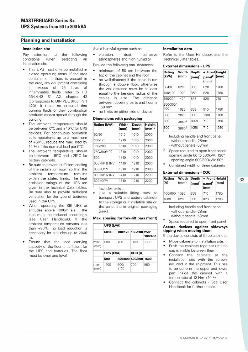
33
Planning and Installation
MASTERGUARD Series SIII
UPS Systems from 60 to 800 kVA
MKA4CAT0UKSIII/Rev. 11-11/2004/UK
Tecnico-SIII-MG 10-11-2004 8:22 Pagina 33

Planning and Installation
MASTERGUARD Series SIII
UPS Systems from 60 to 800 kVA
34
MKA4CAT0UKSIII/Rev. 11-11/2004/UK
Tecnico-SIII-MG 10-11-2004 8:22 Pagina 34

35
Planning and Installation
MASTERGUARD Series SIII
UPS Systems from 60 to 800 kVA
MKA4CAT0UKSIII/Rev. 11-11/2004/UK
Tecnico-SIII-MG 10-11-2004 8:22 Pagina 35

Notes
36
MKA4CAT0UKSIII/Rev. 11-11/2004/UK
Tecnico-SIII-MG 10-11-2004 8:22 Pagina 36