Technology Vehicles - NASA...basis of an assessment of the 5-58 turbojet engine, which uses 1960...
203
\ /- ' ->~ (NASA-Cii- 157444) EARTH-TO-ORETT I POSABLE V79-27 1'32 LAUNCH VYFIICLES: A COMPARATIVE ASSESSHYNT ,- Final Report (Genera 1 Rrsearch Corp., HcLean, Ya.) 202 p HC AlO/MF AG1 CSCL :!2~ rlnclzs 709-02-CR G3/12 26921 Earlh-to-Orbit Reusable Launch Vehicles - A Comparative Assessment - By: Prepared for: National Aeronautics and Space Admintstration Lnngley Reser~rch Center Under Conl~i~ct NASW-2973 for the Office of Aeronautics and Space Technology February 1978 WGRC 78-4673 copy _f ;i of 125 Copies R'ASHINGTON OPERATIONS 7655 OLD SPRtNGriOUSE ROAD A SUBSlUlAnY OF FLOW GENERAL https://ntrs.nasa.gov/search.jsp?R=19790019021 2020-03-15T08:51:44+00:00Z
Transcript of Technology Vehicles - NASA...basis of an assessment of the 5-58 turbojet engine, which uses 1960...

\ /-
'
->~
(N
AS
A-C
ii-
15
74
44
) E
AR
TH
-TO
-OR
ET
T
I P
OS
AB
LE
V79-27 1
'32
LA
UN
CH
V
YF
IIC
LE
S:
A C
OM
PA
RA
TIV
E
AS
SE
SS
HY
NT
,-
Fin
al Report (Genera 1 Rrsearch Corp.,
HcL
ean
, Ya.)
20
2
p H
C
AlO
/MF
A
G1
C
SC
L :!2~
rln
clz
s 709-0
2-C
R
G3
/12
2
69
21
Earl
h-t
o-O
rbit R
eu
sab
le L
aunch V
eh
icle
s
- A
Co
mp
ara
tiv
e A
ss
es
sm
en
t -
By
:
Pre
par
ed
for:
Nat
ion
al A
ero
nau
tics
an
d S
pac
e A
dm
ints
trat
ion
L
nn
gle
y R
eser
~rch
Cen
ter
Un
der
Co
nl~
i~c
t NA
SW
-29
73
fo
r th
e O
ffic
e o
f A
ero
nau
tics
an
d S
pace
Tec
hn
olo
gy
Feb
ruar
y 1978
WG
RC
78
-46
73
c
op
y _
f ;i of
12
5 C
op
ies
R'
AS
HI
NG
TO
N
OP
ER
AT
IO
NS
7
65
5 O
LD
SP
RtN
GriO
US
E R
OA
D
A S
UB
SlU
lAn
Y O
F FL
OW
GE
NE
RA
L
https://ntrs.nasa.gov/search.jsp?R=19790019021 2020-03-15T08:51:44+00:00Z

a u r e a c 0 0 0 4 6 a

EART
H-TO
-ORB
IT
REUS
ABLE
LAU
NCI1
VEH
ICLE
S
- A
COM
PARA
TIVE
ASS
ESSM
ENT
- F
ina
l R
epor
t
PRE
PAR
ED
BY:
Ra
n .
Cd
e
Pr
inc
ipa
l In
ve
stig
ato
r
APP
RO
VED
B
Y:
Tho
mas
M
. Z
ak
rze
Pro
gram
Man
ager
a
M A
sso
cia
te
Dir
ec
tor
, W
ash
ing
ton
O
per
at i
on
s
APP
RO
VE
D
BY
: / D
ire
cto
r,
~a
sv
~t
on
O
pe
ra
tio
ns
GE
NE
RA
L
WA
SH
IN
GT
ON
O
PE
RA
TI
ON
S
76
55
OL
D S
PR
ING
tlO
US
E R
OA
D
WE
ST
GA
TE
R
ES
EA
RC
H
PA
RK
, h
lCL
EA
N.
VA
2
21
01
A SU
BSI
DIA
RY
OF
FLOW
GEN
ERAL
IN
C.


CONT
ENTS
SEC
TIO
N
-
PAG
E -
AB
STR
AC
T i
1
INT
RO
DU
CT
ION
, SU
MM
ARY
, A
ND
C
ON
CL
USI
ON
S
1.1
S
tud
y O
bje
cti
ve
s
1.2
S
umm
ary
of
An
aly
sis
1.3
R
es
ult
s a
nd
C
on
clu
siq
ns
1.4
R
eco
mm
end
atio
ns
REU
SAB
LE
LAU
NCH
V
EH
ICL
E
CO
NC
EPTS
2.1
P
ar
all
el
Lif
t
2.2
C
ow
par
iso
n o
f A
lr-B
rea
thin
g
an
d R
ock
et
Bo
ost
ers
2.3
O
pe
rati
on
al
Co
nc
ep
t
2.4
A
ttri
bu
tes
of
Air
-Bre
ath
ing
T
wo
-Sta
ge
Ve
hic
les
MIS
SIO
N
ASS
ESS
PEN
T A
h LA
UN
CH
VE
HIC
LE
R
EQU
IREM
ENTS
3.1
Sc
en
ari
os
3.2
Mis
sio
n O
pp
ort
un
itie
s
3.3
L
aun
ch V
eh
icle
Re
qu
ire
me
nts
LAU
NCH
V
EH
ICL
E
DE
SCR
IPT
ION
S
4.1
O
rbit
er
Ve
hic
les
4.2
S
ing
le S
tag
e t
o O
rbit
wit
h V
ert
ica
l T
ak
eo
ff
(SST
O-V
Ta)
4.3
S
ing
le S
tag
e t
o O
rbit
wit
h H
ori
zo
nta
l T
ak
eo
ff
(SST
O-H
TO
)
4.4
A
ll-R
ock
et
Tw
o-S
tag
e V
eh
icle

3 m \ O h a c n d . . . . . . u u u u u u

F I G
URES
-
Launch Vehlcle Comparison
Parallel Lift
Propulsion Opt ions
Performance Assessment -
Propulsion
Mission Flight Profile
Ground Operations Profile
Typical Ground Operat ions Flow
Air
-lir
ra
rh
ing
Launch Vehicle Attributes
Future Scenarios
Summary of Mission Classes
Typical Mission OpporCunities
Launch Vehicle Requirements Summary
Orbiter for Hypersonic Uooster Systems
Rocket Orbiter for Suhsonic Parallel-Lift Single Baoster
PAG
E -
3
9
10
12
14
15
17
18
22
2 4
2 6
28
30
33
Single-Stage-to-Orbit Launch Vehicle (Vertical Takeoff, Horizontal Landing) 34
Single-Stage-to-Orbit Launch Vehicle (Horizontal Takeoff and Landing)
36

m \ D m u u u

FIGU
RES
(Co
nt.
)
NO. -
PAG
E
6-4
Mis
sio
n P
ote
nti
al
64
6-5
Op
era
tio
ns
Co
st
Per
F
lig
ht
66
6-6
Op
era
tio
ns
and
M
ain
ten
ance
M
ann
ing
6 7
6- 7
A
ttr
ibu
te
Ass
essm
ent
Sum
mar
y 6
9
vii

1
INTRODUCTION, s
UW
RY
, AND CONCLUSIONS -
1.1
STUDY OBJECTIVES
The Hypersonic Branch of the Langley Research Center (LaRC) Lasked General Research Corporation
(GRC)
in June 1977 to assess the utility of fully reusable two-stage launch vehicles incorporating air-
breathing propulsion.1 The specific objectives of the study were:
1
To establish a set of launch vehicle requirements based on an assessment of future NASA
and military mission opportunities.
2
To establish for comparison purposes a set of launch vetlicle candidates which would be
representative of different levels of technology.
3
To assess the utility of two-stage launch vehicles incorporating air-breathing propulsion
in the booster stage by determining the performance, cost, technology needs, technology
risk, and associated benefits of both these vehicles and competitive nonair-breathing
vehicles.
In evaluating the air-breathing candidates, the preferred staging Mach number
was to be identified (i.e., subsonic, supersonic, or hy~ersonic).
A specific two-stage launch vehicle design comprised of an orbiter and twin air-breathing
b0oste.s capable of Mach 3.5 was suggested by LaRC.
Each booster is powered by eight 350,000-380,000 N
(80,000-85,000 lbf) supersonic turbojets.

j o (I: I C
8 : Z:
L
aY
0
..c : C U a M c .d M a U m L
(I: L aJ u
A rl 4 a U c: 0 N rl & 0 s ui Q 0
PI A a U
< U a Y u X Y
(I: aJ rl U rl C a) > rl rl m 3 c (d
L
h rl 4 a -1 t: O N -4 L 0 C - C 4 rl
a 3 rl U -4 - - s rl 4 (3
44
3
(I: 0 sC r: bJ (I:
rl 4 1
4[ c rl b 3 a u rU -4 rl
aJ 'D rl 3 0 L a V) M C rl 3 & PI U (I: 0 0 n a c a L aJ U rl n & 0
C U 3 n U m C U
01 U 0 c a 0
3 U
0 aJ 3 a -4
- - U w rl rl
rf CJ 4 4 Q L TJ a - - E al u
2 - +
rl M 0
a m 4J aJ m M
a X u P (I:
. -0 (I: C o m


system (TPS), the development of a fully reusable launch vehicle depends upon demonstrated advances
in TPS technology, which may be provided by the Shuttle.
The results of the cost assessment indicate that a fully reusable launch vehicle may reduce
the cost per flight by 60-80% compared to that of the Shuttle. The elimination of expendable and
refurbished hardware requirements would provide a 50% reduction in cost. Increased efficiency,
reduced opel-ations and maintenance manpower, and elimination of facilities indicate a further re-
duction of 50% of the remaining costs. Total savings could run as !>ish as $
34B
over 10 years,
compared to the Shuttle, which is more than the proposed total program cost for the reusable launch
vehicle.
The GRC assessment further indicates that a two-stage parallel-lift launch vehicle would re-
quire a slightly higher initial cost than an SSTO, but would have a lower cost per flight, resulting
in a total program cost that is approximately the same. The parallel-lift vehicles would also have
more operational flexibility, reflected in extended range for self-ferrying, and greater capability
for offset orbit injection, loiter, and recall.
In addition, the parallel-lift launcn vehicles
represent lower development risk because of the high uti1iza:ion
of existin, technology, engines,
and
subsystems.
A twin-booster subsonic-staged parallel-lift vehicle represents the lowest cost and development
risk.
However,it would appear that the investment in thc development of a new high-thrust turbojet
engine for the supersonic parallel-lift vehicle would return tt:e development cost in total program
savings such that the supersonic parallel-lift vehicle would be tibe econolnic choice. It must be
cautioned, however, that the cost difference between the most economic alternatives may not be sig-
nificant because of the uncertainties in the cost estimates.
5

1.4
K
EC
O~l
FlE
NIIA
TT
ON
S
Th
e c
urs
ory
css
ess
me
nt
of
two
-sta
ge
la
un
ch
ve
hic
les
e
mp
loy
ing
air
-bre
ath
ing
b
oo
ste
rs a
s
pre
se
nte
d
311
this
stu
dy
in
dic
ate
s
tlla
t th
eir
u~
il
it
y is s
uf
fic
ien
t t
o j
us
tif
y
ad
dit
ion
al
stu
die
s.
'The
c
on
ce
pt
of
pa
ra
lle
l l
if
t h
as
op
en
ed
a
f
er
tile
new
a
rea
fo
r g
en
era
tin
g
lau
nc
h v
eh
icle
op
tio
ns
.
Th
e p
res
en
t s
tud
y h
as
zo
ns
ide
red
on
ly
thre
e p
ar
all
el-
lif
t v
eh
icle
c
on
ce
pts
an
d a
s
ing
le p
ay
loa
d
siz
e.
A
su
pe
rso
nic
p
ar
all
el-
lif
t v
eh
icle
in
th
e 5
,00
0-1
0,0
00
k
g p
ay
loa
d
cla
ss
is a
n
in~
er
es
tin
g
op
tio
n a
s a
ve
hic
le o
f th
at
siz
e c
ou
ld
use
ex
isti
ng
su
pe
rso
nic
en
gin
es
. T
he
pre
ferr
ed
s
tag
ing
Mac
h
nu
mb
er
ne
ed
s fu
rth
er
stu
dy
. T
he
Mac
h 3
.5
sta
gin
g c
on
sid
ere
d h
ere
fo
r t
he
su
pe
rso
nic
ve
hic
le w
as
se
lec
ted
on
th
e b
as
is o
f a
n a
sse
ssm
en
t o
f th
e 5
-58
turb
oje
t e
ng
ine
, w
hic
h
us
es
19
60
te
ch
no
log
y.
Uti
liz
ati
on
of
a m
ore
a
dv
an
ce
d
en
gin
e c
ou
ld
sig
nif
ica
ntl
y
ch
an
ge
th
e o
pti
mu
m
sta
gin
g X
ach
n
um
ber
.
To
as
sis
t in
de
term
inin
g tl
ie
pre
ferr
ed
s
tag
ing
Mac
h n
um
ber
f
or
an
air
-bre
ath
ing
p
ar
all
el-
lif
t
ve
hic
le,
it i
s r
eco
mm
end
ed h
at
d
da
ta b
ase
b
e
ob
tain
ed
fo
r tu
rbo
jet
en
gin
es
wh
ich
wo
uld
a
ss
ist
in
se
lec
tin
g t
he
ty
pe
of
en
gin
e m
ost
s
uit
ab
le f
or
a
pa
ra
lle
l-li
ft
ve
hic
le a
pp
lic
ati
on
. RDTSE c
os
t
es
tim
ate
s a
ss
oc
iate
d w
iLh
L
l~
e de
ve
lop
me
nt
of
a s
up
ers
on
ic t
urb
oje
t e
ng
ine
s
pe
cif
ica
lly
fo
r a
pa
rall
el-
lif
t v
ell:
cle
wo
uld
b
e
us
efu
l.
Se
ve
ral
imp
ort
zn
t n
ee
ds
fo
r s
up
po
rtin
g t
ec
hn
olo
gy
ha
ve
b
ee
n
ide
nti
fie
d.
Th
e th
erm
al
pro
tec
tio
n
syst
em
fo
r a
f
ull
y r
eu
wh
le v
eh
iclc
: w
ill,
to
a
larg
e e
xte
nt,
d
ep
en
d
on
th
e
su
cc
es
s o
f th
e S
hu
ttle
TP
S.
Ho
wev
er,
the
nii
li L
ar y
use
of
an
Ea
r tll
- to
-orb
it
lau
nc
h v
eh
icle
c
ou
ld
imp
ose
e
nv
iro
nm
en
tal
req
uir
em
en
ts t
ha
t I
II
~~
Y on
ly
be
sa
tis
t ir
d b
y a
mo
re
adv
arrc
ed
TP
S
tha
n
tha
t o
n
the
Sh
utt
le.
It w
ou
ld
ap
pe
ar
de
sir
ab
le
to s
up
po
rt d
ev
elo
pw
nt
of
me
tall
ic '
KPS
o
r s
till m
ore
a
dv
an
ce
d
RS
I c
on
ce
pts
.
Stu
die
s t
o d
ate
ha
ve
in
dic
ate
d
tha
t th
e
tra
ns
on
ic d
rag
of
pa
ra
lle
l-li
ft
ve
hic
les
is a
ke
y
Eac
to
r
in e
ng
ine
th
rus
t-le
ve
l s
ele
cti
on
. L
aRC
is
pre
se
ntl
y
pla
nn
ing
lim
ite
d w
ind
tu
nn
el
tes
tin
g

2 R
EUSA
BLE
LA
UN
CH
V
EH
ICL
E
CO
NC
EPTS
2.1
PA
RA
LLEL
L
IFT
The
lau
nc
h v
eh
icle
in
itia
lly
pro
po
sed
by
LaRC r
ep
res
en
ts a
new
c
on
ce
pt,
c
all
ed
"p
ara
lle
l li
ft"
P
-
in
th
is s
tud
y.
Pa
rall
el
li
ft
is
ilju
str
ate
d b
y
the
tw
o
ve
hic
les
sh
ow
n
in
Fig
. 2-
1.
In t
he
ve
hic
le
t w
ith
ou
t p
ara
lle
l l
if
t,
the
bo
os
ter
pro
vid
es
the
en
tir
e l
if
t d
uri
ng
ta
ke
off
a
nd
cli
mb
an
d
rese
mb
les
.-.
a
ve
ry l
arg
e t
ran
sp
ort
air
cra
ft.
In t
he
pa
rall
el-
lift
v
eh
icle
, b
oth
th
e o
rbit
er
and
b
oo
ste
r w
ing
s
pro
vid
e
li
ft
du
rin
g t
ak
eo
ff
and
c
lim
b.
Th
is p
erm
its
the
bo
osz
er
to b
e r
ed
uc
ed
b
y
ap
pro
xim
ate
ly o
ne-
. ..
thir
d
in s
ize
an
d w
eig
ht.
T
he
or
bit
er
win
g is
siz
ed
pri
ma
rily
to
wit
hst
an
d r
ee
ntr
y h
ea
tin
g.
The
bo
ost
er
win
g is
siz
ed
fo
r fl
yb
ac
k a
nd
la
nd
ing
, b
ut
is m
od
ifie
d
to b
ett
er
mat
ch
the
orb
ite
r w
ing
fo
r
tak
eo
ff
(to
ho
ld
tak
eo
ff
spc
cd
w
ith
in
the
lim
its
of
sta
te-o
f-th
e-a
rt
tire
s).
T
hre
e p
ara
lle
l-li
ft
ve
hic
les
we
re e
va
lua
ted
i
n t
his
stu
dy
(s
ee
S
ec.
4).
r-
b-
2.2
COMPARZSON O
F A
IR-B
RFA
THZN
G
AN
D
RO
CK
ET
BO
OST
ERS
.. . A
ir-b
rea
thin
g
pro
pu
lsio
n
for
Ea
rth
-to
wrb
it
lau
nc
h v
eh
icle
s h
as
bee
n
stu
die
d s
ev
era
l ti
me
s
sin
ce
th
e e
arl
y 1
96
0s.
T
he
co
nti
nu
al
inte
res
t i
n a
ir-b
rea
thin
g
pro
pu
lsio
n is
du
e p
rim
ari
ly
to
th
e
& --
hig
h
en
gin
e s
pe
cif
ic i
mp
uls
e
(I
) o
bta
ina
ble
--a
fa
cto
r o
f 1
0 b
ett
er
fo
r h
yd
rog
en
-fu
ele
d
air
-bre
ath
ing
s P
pro
pu
lsio
n s
yst
em
s co
mp
ared
tu
hy
dro
ge
n-f
ue
led
ro
ck
et
syst
em
s.
Ho
wev
er,
whe
n c
on
sid
ere
d
i.n
th
e c
on
- -.
tex
t o
f o
ve
rall
Sy
sLru
l p
er
for~
ua
nc
e, t
he
wel
l-k
no
wn
e
ng
ine
sp
ec
ific
im
pu
lse
ad
va
nta
ge
s sh
ow
n
in
Fig
. -
2-2
tra
ns
late
in
to l
ess a
dv
an
tag
eo
us
syst
em
~e
rfo
rma
nc
e eff
ec
ts.


Fig
ure
2-3
PERF
ORM
ANCE
ASS
ESSM
ENT - P
ROPU
LSIO
N
Effe
ctiv
e Sp
eclfi
c Im
puls
e,
Turb
ojet
+
Scra
mje
t Tu
rboj
et B
oost
er,
Boos
ter,
Rock
et O
rbite
r Ro
c ke!
Orb
iter
Turb
ojet
Boo
ster
, '"1 s
g Rock
et O
rbite
r Ro
cket
Bo
oste
r, Ro
cket
I
Orb
iter
Stag
ing
Mac
h N
umbe
r
2.3
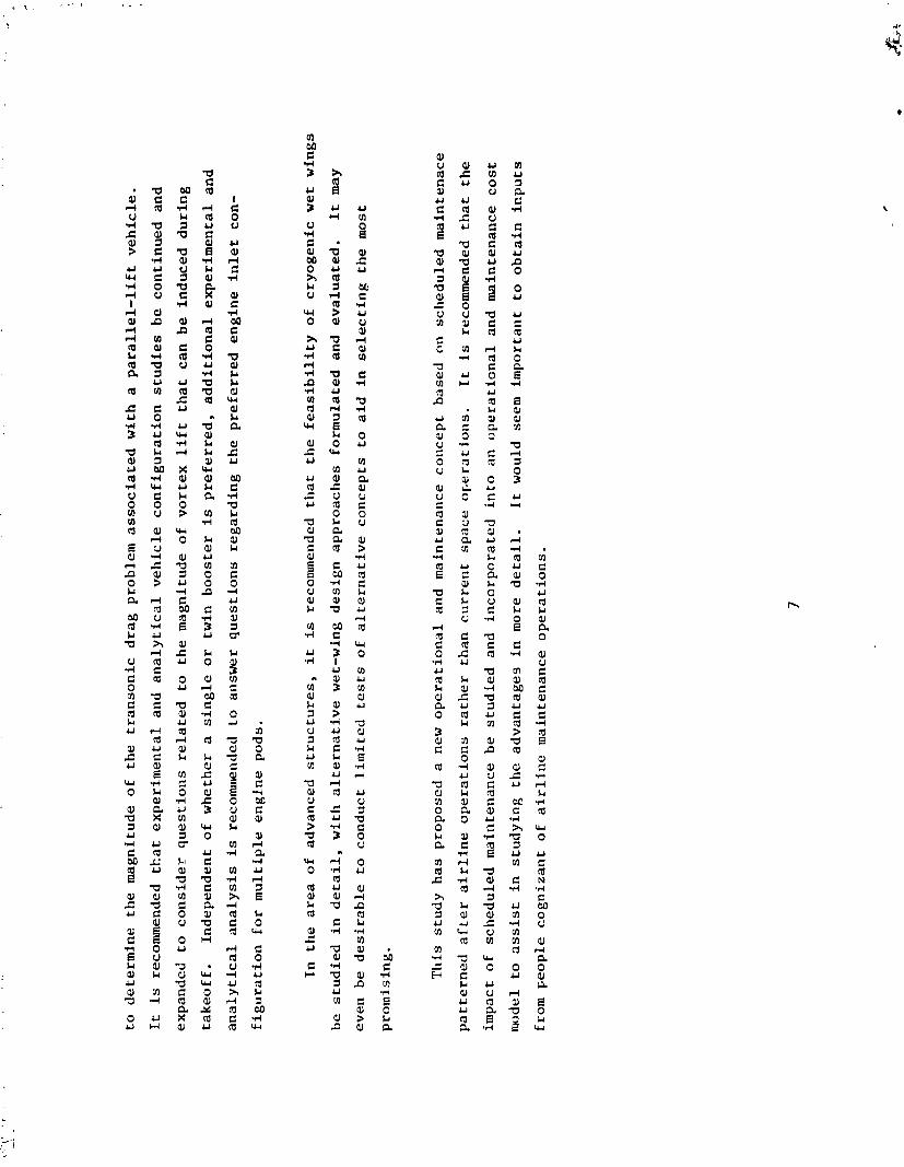
OPERATIONAL CONCEPT
A typical mission profile (shown in Fig. 2-4) for a horizontal-takeoff two-stage launch vehicle
consists of:
1
A liorizontal takeoff and climb to staging altitude and Mach number using an air-breathing
booster.
2
At staging, the orbiter main engine is started and the booster engines are throttled Lack
to allow the orbiter to fly away from the booscer(s).
3
The Looster(s)
then flies (fly) back to the launch site, either piloted or remotely
guided for a horizontal landing.
4
The orbiter continues into orbit after staging, delivering its payload, and returning
to either the launch site or an alternative lsnding site, and lands horizontally.
A ground operations profile for the parallel-lift two-stage launch vehicle is shown in Fig.
2-5.
After landing, the orbiter is retrieved by
a tow vehicle wtiich supplies a
1 1 ground power
(electrical, pneumatic, transport).
The orbiter is taken directly to a deservicing facility, where
any returned payload is removed.
In the deservicing facil?ty, the hydrogen propellant lines and
propellant tanks are purged
to eliminate any residual hydrogen gases a.id
liquids which could be
a potential explosion hazard.
Any other potentially hazardous material Is also removed. After de-
servicing, the orbiter is towed to the maintenance and assembly facility for routine checkout and
servicing of noncritical, scheduled-maintenance items. All unscheduled maintenance is also completed,
a2d
the orbiter is prepared for baoster mating.
The boosters are serb-ced prior to the ~rblter
return an0 are available for the mating operatiun as soon as the orbiter is ready.
In the case
of the two-booster configuration, it
is envisioned that the boosters would be sufficiently lowered

MIS
SIO
N FL
IGHT
PRO
FILE

Fig
ure
2-5
GROU
ND O
PERA
TION
S PR
OFIL
E (6
0 llo
ur T
urna
roun
d Tl
r~~e
)
Frop
alla
nt
find
Con
sm ab
le
Serv
icin
g Fa
cilll
y
O~b
ilcr
C
l~ec
kot~
l, M
afnl
ena~
~ce,
As
se~n
l~ly
h
d
Payl
oad
Insl
alla
lion
Faci
lily
.-
Jet
Engl
ne S
lart
Po
wer
Tran
sler
4-
fi.9-
- . --
Land
ing
Fow
cr T
~ans
fcr
Tad
for
Take
off
01 bi
ler
Desc
rvic
lr~g
Faci
lily
Boor
tsr
Cl~
ccko
r~l
And
Mai
nlen
ancc
Fa
cilil
y
-
15
G.R
c &I
-

by
hy
dra
uli
c-a
ctf
i.a
ted
la
nd
ing
ge
ar
to a
llo
w t
hem
to
be
to
wed
u
nd
er
the
orb
ite
r w
ing
s.
Th
e
bo
ost
ers
wo
uld
th
en
be
ra
ise
d a
nd
mat
ed
to t
he
orb
ite
r.
Aft
er
the
ma
tin
g o
pe
rati
on
, th
e a
sse
mb
led
ve
hic
le u
nd
erg
oes
a
n i
nte
gra
ted
op
era
tio
ns
ve
rifi
ca
tio
n.
Nex
t th
e p
ay
loa
d is
lo
ad
ed
an
d
the
ve
hic
le
tow
ed
to t
he
pro
pe
lla
nt
and
co
nsu
mab
le s
erv
icin
g f
ac
ilit
y,
wh
ere
fin
al
pre
pa
rati
on
s fo
r fl
igh
t are
com
ple
ted
.
The
c
rew
bo
ard
s th
e v
eh
icle
du
rin
g t
he
fi
na
l s
tag
es
of
pro
pe
lla
nt
loa
din
g t
o c
on
du
ct
the
fin
al
pre
flig
ht
ch
ec
ko
ut.
T
hen
th
e v
eh
icle
is
to
wed
o
nto
th
e r
un
way
a
pro
n,
wh
ere
the
je
t e
ng
ine
s a
re
sta
rte
d,
and
po
wer
is
tra
ns
ferr
ed
fr
om
gro
un
d
to o
n-b
oar
d
syst
em
s.
Th
e v
eh
icle
is
now
re
ad
y
for
tak
eo
ff.
Bas
ed
on
th
e t
ime
lin
e s
how
n in
Fig
. 2
-6,
it i
s e
stim
ate
d
tha
t th
is t
urn
aro
un
d
co
uld
be
ac
co
mp
lish
ed
in
60 h
ou
rs o
ve
r a
2.5
-day
p
eri
od
, as
sum
ing
a
thre
e-s
hif
t o
pe
raii
on
.
2.5
AT
TRIB
UTES
OF AIR
-BRE
ATHI
NG
TWO
-ST-
4GE
VE
HIC
LE
S
Fig
ure
2-7
li
sts
th
e a
ttri
bu
tes
of
air
-bre
ath
ing
rc
usa
ble
ve
hic
les.
A
s a
lre
ad
y n
ote
d,
al
l
lau
nc
h v
eh
icle
s c
on
sid
ere
d
in t
lrr
stu
dy
are
ass
um
zd
to b
e fu
lly
re
usa
ble
, n
ot
req
uir
ing
re
co
ve
ry,
refu
rnis
hm
en
t,
or
re
pla
ce
we
nt
op
era
tio
ns
suc
h a
s t
ho
se a
ss
oc
iate
d w
ith
th
e S
hu
ttle
so
lid
ro
ck
et
mo
tors
(SRM).
Ho
riz
on
tal
ass
em
bly
, ta
ke
off
, an
d
lan
din
g o
pe
rati
on
s a
re c
om
pa
tib
le w
ith
th
is c
on
ce
pt
and
wo
uld
a
pp
ea
r to
re
su
lt i
n a
pp
rec
iab
le s
av
ing
s o
f c
os
t an
d
tim
e c
om
par
ed
to v
ert
ica
l a
sse
mb
ly
and
la
un
ch
op
era
tio
ns,
sin
ce
no
la
un
ch
pad
o
r m
ob
ile
la
un
ch
er
is r
eq
uir
ed
. It
is a
ssu
med
th
at
air
-
bre
ath
ing
de
sig
ns
ar
e c
om
pa
tib
le w
ith
ex
isti
ng
ru
nw
ays
(as
lo
ng
as
th
e b
ea
rin
g p
ress
ure
on
th
e r
un
-
way
is
ke
pt
at
cu
rr
en
t le
ve
ls),
?
he
reb
y e
xte
nd
ing
la
un
ch
sit
e o
pp
ort
un
itie
s
to a
ny
sit
e w
ith
ad
eq
ua
te
run
way
le
ng
th a
nd
th
e a
va
ila
bil
ity
of
cry
og
en
ic s
erv
icin
g.
Hen
ce,
reu
sab
le a
ir-b
rea
thin
g
bo
os
ters
co
uld
pro
vid
e e
xte
nd
ed
ra
ng
e o
pe
rati
on
s e
na
bli
ng
re
mo
te l
au
nc
h s
ite
op
era
tio
ns
wh
ile
re
tain
ing
the
ad
va
nt
a~
~s
o
f c
er-
tra
liz
ed
ma
inte
na
nc
e.
In-f
lig
ht
refu
eli
ng
of
the
bo
ost
er
wo
uld
e
na
ble
th
e
lau
nc
h v
eh
icle
to
be
fl
ow
n
to o
r f
rom
an
y p
lac
e d
esi
red
. T
he
inc
rea
sed
e
ffic
ien
cy
of

Fig
ure
2-6
TYPI
CAL
GROU
ND O
PERA
TION
S FL
OW
(PAR
ALLE
L-LI
FI V
EHIC
LE)
TIM
E FR
OM
TOU
CHDO
WN
(HR)
0
10
2
0
30
40
6
0
60
I I
I I
I I
I
0 LA
ND
ING
, C
ON
NE
CT
SE
t7V
lCE
LIN
ES
, T
RA
NS
FE
R T
O G
RO
UN
D P
OW
ER
, TO
W T
O O
RB
ITE
R
DE
SE
RV
lClN
G F
AC
ILIT
Y
17
S
AF
ING
AN
D D
ES
ER
VlC
lNG
(D
RA
IN A
ND
PU
RG
E P
RO
PE
LL
AN
T S
YS
TE
M)
RE
MO
VE
PA
Y L
OA
D (C
An
GO
)
0 TR
AN
SF
ER
TO
CH
EC
KO
UT
AN
D M
AIN
TE
NA
NC
E F
AC
ILIT
Y
1-1 V
EH
ICL
E C
HE
CK
OU
T,
NO
RM
AL
PR
EF
LIQ
I-IT
MA
INT
EN
AN
CE
1-1 M
AT
E B
OO
ST
ER
S
(-1 IN
TE
GR
AT
ED
OP
ER
AT
ION
S V
ER
IFIC
AT
ION
1)
P
AY
LO
AD
LO
AD
ING
(C
AR
GO
)
TR
AN
SF
ER
TO
PR
OP
EL
LA
NT
AN
D C
ON
SU
MA
BL
E
SE
RV
ICIN
G F
AC
lLl.C
Y
PR
OP
ELL
AN
TS
AN
D C
ON
SU
MA
BLE
SE
RV
ICIN
G
(-
1 O PR
OP
ELL
AN
T T
OP
OF
F
Cn
EW
LO
AD
ING
, F
INA
L C
tlEC
KO
FF
, R
OL
LO
UT
, S
TA
RT
EN
GIN
ES
, T
AX
I 1-1
RE
AD
Y F
OR
TA
KE
OF
F 0 C
RC
17

r.
Figu
re 2
-7
AIR-
BREA
THIN
G LA
UNCH
VEH
ICLE
ATT
RIBU
TES
a FU
LLY
REUS
ABLE
MU
NC
H V
EHIC
LE
a HO
RIZO
NTAL
ASS
EMBL
Y
e HO
RIZO
NTAL
TAK
EOFF
AND
LAN
DING
e M
ULTI
PLE
MU
NC
II, M
UU
'I PLE
LAN
DING
SIT
ES
e EX
TEND
ED R
ANGE
e OF
FSET
ORB
IT I
NJEC
TIO
N
e PA
RALL
EL B
URN
e LO
I1'ER
e SC
HEDU
LEU
MAI
NTEN
ANCE
I
GR
C
18

air-breathing engines compared to rocket engines would enable a 200-km offset orbit injection capa-
bility to be included in the nominal fuel loading.
The offset range could be used for loiter or
recall to the launch site after takeoff.
Extended ferry operations offer the opportunity of using remote launch sites in equatorial
regions or foreign countries. Foreign lease of a launch vehicle for a specific period of time,
compatible with scheduled maintenance, could be desirable in terms of international relations.
A fully reusable launch vehicle would not have launch azimuth restrictions imposed by
falling
solid rocket boosters and external tanks.
Hence launch operations could be conducted from various
sites (some inland), or all launches could be cunducted from a single site, eliminating the need
for
East Coast and West Coast launch sites (as with the Shuttle) to satisfy mission requirements. Sav-
ings in launch site costs could easily run into hundreds of millions of dollars.
For applications in which time-to-orbit
is a key factor, a parallel-burn launch is possible:
the orbiter rocket engines are started once the vehicle starts its ground roll, or as soon as the
vehicle is airborne and a safe distance from the runway, to prevent damage due to rocket exhaust
impingement.
(Local noise ordinances are a consideration as well.)
Another advantage of a parallel-
burn capability is that it might permit the use of lower thrust ~urbojet engines, alleviating the
need for a high-thrust engine development program.
The most important advantage of reusable vehicles identified in this study is scheduled main-
tenance operztions. If the maintenance schedule proposed here can be achieved, an increase in launch
vehicle utilization results, and this is reflected in sinnificant reductions i.1
operating costs.

(Indications are that a factor of at least 2 relative to the Shuttle may be achievable in launch
vehicle utilization rates.)
The ground operations timelines are based on a maintenance schedule
thnt assumes for the launch vehicle a reusable TPS that requires refurbishment only after seven
flights. Technological advances are required before the outlines operations schedule can be
achieved.

3
MIS
SIO
N A
SSES
SMEN
T A
ND
LA
UN
CH
VE
HIC
LE
R
EQU
IREM
ENTS
1
Bas
ed
on
a
surv
ey
of
pro
po
sed
ad
van
ced
sp
ac
e s
yst
em
s (b
oth
NA
sA*'
~ a
nd
mil
ita
ry ),
m
issi
on
op
po
rtu
nit
ies
wer
e id
en
tifi
ed
an
d
ca
teg
ori
ze
d a
cc
ord
ing
to
fu
nc
tio
n,
e.g
.,
ob
serv
ati
on
, co
mm
uni-
ca
tio
ns
, w
eap
on
s,
and
se
rvic
es
. I
n p
ara
lle
l w
ith
th
e m
issi
on
cla
ss
ific
ati
on
, s
ev
era
l sp
ac
e
sc
en
ari
os
pro
po
sed
by
th
e H
udso
n in
stitu
te4
and
th
e A
ero
spa
ce
co
rpo
rati
on
5 w
ere
rev
iew
ed
an
d
con
den
sed
. T
he
sc
en
ari
os
an
d
the
mis
sio
n d
ata
we
re t
he
n c
om
bin
ed
to p
rov
ide
sp
ec
ific
la
un
ch
ve
hic
le p
ay
loa
ds
and
de
liv
ery
orb
its
. T
he
res
ult
s c
an
be
use
d t3 d
efi
ne
fu
ture
Ea
rth
-to
-orb
it
lau
nc
h v
eh
icle
re
qu
ire
me
nts
. N
o a
tte
mp
t w
as
mad
e to
es
tab
lis
h a
s
pe
cif
ic &
ch
pa
ylo
ad
mo
del
suc
h a
s t
ha
t c
urr
en
tly
in
use
fo
r S
hu
ttle
pla
nn
lnb
pu
rpo
ses.
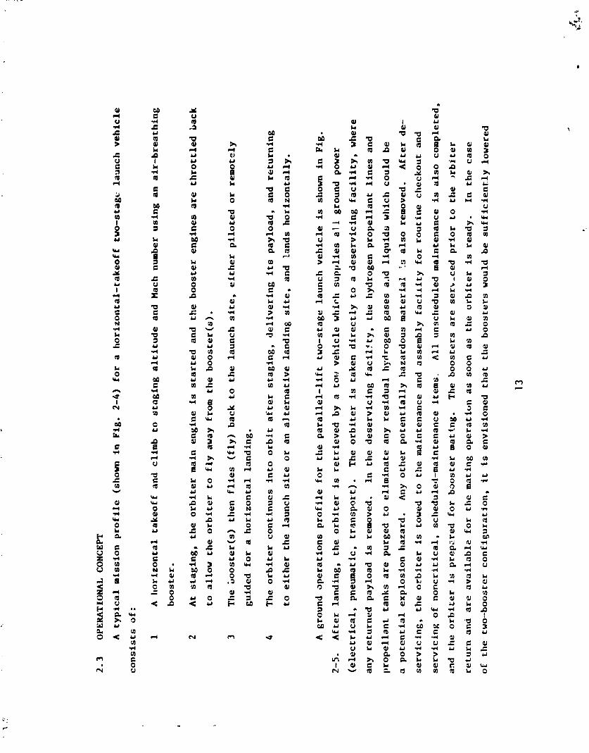
3.1
SC
EN
AR
IOS
The
Hu
dso
n
Ins
titu
te a
nd
th
e A
ero
spa
ce
C
orp
ora
tio
n s
ce
na
rio
s (
Fig
. 3-
1)
wer
e co
nd
ense
d
into
: (1)
bu
sin
ess
as
usu
al
wit
h n
crm
al
gro
wth
, an
d
(2)
the
ra
pid
ex
pa
nsi
on
o
f sp
ac
e o
pe
rati
on
s.
a'@ zg
0-
g 2~
3.1
.1
Sc
en
ari
o N
o.
1
5%
It i
s a
nti
cip
ate
d
tha
t th
e S
hu
ttle
wi
ll
ev
en
tua
lly
bec
om
e a
s
uc
ce
ss
ful
en
terp
ris
e,
and
th
at
*@
5P
co
mm
erci
al u
se o
f sp
ac
e w
ill
gra
du
all
y i
nc
rea
se
as
bu
sin
ess
ve
ntu
res
pro
ve
ec
on
om
ica
lly
su
cc
ess
-
3 9
fu
l.
A
reu
sab
le o
rbit
al
tra
ns
fer
ve
hic
le
(01V
) w
ill
be
de
ve
lop
ed
to
co
nd
uc
t E
art
h o
rbit
al
op
era
- 4
tio
ns
an
d p
rov
ide
low-Earth-to-geosynchronous-orbit
tra
ns
fer.
(A
v
eh
icle
th
at
co
uld
re
ac
h g
eo-
syn
ch
ron
ou
s o
rb
it a
nd
re
turn
wo
uld
a
lso
be
ab
le t
o o
pe
rate
th
rou
gh
ou
t c
is-l
un
ar
spa
ce
as
th
e
nee
d
oc
cu
rre
d.)
T
he
OTV
wil
l b
e E
art
h b
ase
d
and
u
po
n
oc
ca
sio
n r
efu
ele
d i
n l
ow
E
art
h o
rbit
.
The
to
tal
dem
and
for
Sh
utt
le f
lig
hts
is n
ot
ex
pe
cte
d
to e
xc
ee
d 100 p
er
ye
ar.
It i
s n
ot
lik
ely
tha
t a
new
E
art
h-t
o-o
rbit
la
un
ch
ve
hic
le w
il
l b
e d
ev
elo
pe
d.
SCEN
AR I0
WIT
H N
OR
MAL
GRO
WTH
(1
00 S
lIUTl
Lt:
FLIG
I ITS
PER
YtA
R)
BREA
KTHR
OUG
H W
I1-i
THE
RA
PID
EXP
ANSI
ON
OF
SPA
CE O
PERA
TIO
NS
(100
9 LA
UN
CII V
iIilC
LC:
FLIG
HTS
PER
YLA
R)
Fig
ure
3-1
FUTU
RE S
CENA
RIOS
EXPE
CTED
SPA
CE A
CTI
VITY
0
SHU
llLE
IS S
UCCE
SSFU
L
e SP
ACE
BUSI
NES
S AP
PLIC
ATIO
NS
ARE
SUCC
ESSF
UL
e ST
EADY
USE
OF
C I S
-LUN
AR
SPAC
E AF
TER
1980
's
e A
CtI
AtX
E O
CCUR
S -
IN TE
CHNO
LOGY
, PU
BLIC
OPI
NIO
N,
OR S
PACE
EXP
LORA
TIO
NIEX
PLO
ITAT
ION
8
RA
PID
RED
UCTI
ON
IN S
PACE
TRA
NSPO
RTAT
ION
CO
STS
a IM
PRO
VED
RET
URNS
FRO
M S
PACE
INV
ESTM
ENTS
0
RA
PID
EXP
ANSI
ON
IN
SPA
CE S
ERVI
CES
AND
ACTI
VITI
ES
0
RETU
RNS
FRO
M S
PACE
SER
VICE
S AN
D A
CTI
VITI
ES
STRO
NGLY
AFF
ECT
EVEN
TS O
N EA
RTH
GR
C
22

3.1.2
Scenario No. 2
It is assumed that a breakthrough will dramatically change the demand for space utilization,
The nature of the breakthrough could be a change in the public's perception of space, a technologi-
cal
.vent that makes space operations extremely desirable, or a discovery that changes the need for
space operations.
Extremely profitable space investments could initiate a strong competitive demand
and, of course, a recognized military advantiige could accelerate competition between nations.
The
achievement of very low transportation costs could also establish a strong demand for space utiliza-
tion.
Whatever the cause, it is postulated that a rapid increase in space operations can be expected.
Orbital transfer vehicles will be space based.
Several hundred launches per year are anticipated.
3.2
MISSION OPPORTUNITIES
More than 500 near- and far-term proposed advanced space systems were surveyed.
The systems
were categorized functionally as observation, communications, weapons, and support operations.
Each
category was further divided into classes of missions (Fig.
3-2).
Corresponding to each of the two
scenarios above, a set of typical missions was derived from within the mission classes (Fig.
3-3);
they are representatice of the spectrum of expected launch vehicle payload and space operations
requirements.
In the business-as-usual scenario (#l), the launch vehicle is required to carry a
variety of individual spacecratt for near-earth and deep-space operations and to serve as (1) a
spacecraft launch facility; (2) a spacecraft maintenance and repair facility; (3) a short-duration
space laboratory and habitat; (4) an orbital-transfer-vehicle delivery, launch and retrieval system;
and (5) an Earth orbital construction facility, including provisions for teleoperator services.
The
launch vehicle has a high degree of in-orbit flexibility in order to conduct short-term space support
functions to compensate for the lack of space basing.

Fig
ure 3-2
SUM
MAR
Y OF
MIS
SIO
N CU
SSES
SPAC
E FU
NCTI
ON
1 NA
SA M
ISS
ION
S
I M
lLiT
AR
Y M
ISS
ION
S
IAN
0 O
CEAN
S AT
MO
SPW
ERlC
SOLA
R SP
ACE:
NEA
R EA
RTH,
DEE
P SP
ACE
IhiT
RAG
OVE
HNM
ENT
GO
VERN
MEN
T PE
OPLE
PEOP
LE
PEOP
LE
lAN
D O
CEAN
S AT
MO
SPHE
R IC
SO
LAR"
NEAR
EAR
TH S
PACE
NATI
ONA
L C
OM
AN
O &
CO
NTRO
L
INTR
ATHE
ATER
I NTE
RTtIE
ATER
ST
RATE
GIC
FO
RCES
SPEC
IAL
OPE
RATI
ONS
SPAC
E- B
ASED
OFF
EN S
l VE
&
DEFE
NSIV
E W
EAPO
NS
GROU
ND-B
ASED
SP
ACE
DEPL
OYA
BLE
OFF
ENSI
VE &
DEF
ENSI
VE W
EAPO
NS
GR
C
>
24

Fig
ure
3-2 (
Co
nt.
)
SUM
MARY
OF
MIS
SIO
N CL
ASSE
S (Co
nt.)
SPAC
E FU
NCTI
ON
I N
AS
A M
ISS
ION
S
I M
ILIT
AR
Y M
I SSI
ON
S
(Cat
egor
ies)
SUPP
ORT
NA
VIG
ATl
(N
TRAN
SPO
RTAT
ION
CONT
ROL
ENER
GY
PRO
DUCT
ION
& T
RANS
FER
ENVI
RO
IWEN
T M
OD
IFIC
ATIO
N
MAN
UFAC
TUR
ING
RDT&
E A
CTI
ViT
IES
DIS
POSA
L &
CONT
ROL
OF W
ASTE
M
ATER
IAL
SPAC
E CO
N ST
ROCT
I ON
SPAC
E DE
LIVE
RY &
MAI
NTE
NAN
CE
SPAC
E TR
ANSP
ORT
ATIO
N
MAN
NED
SPAC
E O
CCUP
ANCY
NAV
IGAT
ION
TRAN
SPO
RTAT
I (IN
CO
NTRO
L
ENER
GY P
RODU
CTIO
N &
TRAN
SFER
ENVI
RO
NMDJ
T M
OD
IFIC
ATIO
N
RDT&
E A
CTI
VIT
IES
D! S
POSA
L &
CO
lUTR
OL W W
ASTE
M
ATER
l AL
SPAC
E T
RM
SPO
RTAT
ION
SPAC
E C
ON
STR
LCTI
W
SPAC
E DE
LIVE
RY &
Pf I
INTE
NAN
CE
MAN
NED
SPAC
E O
CCUP
ANCY


In t
he
ra
pid
ex
pa
nsi
on
sc
en
ari
o (
12
), a
h
igh
le
ve
l o
f sp
ac
e-b
ase
d
op
era
tic
ns
is p
rov
ide
d b
y
fa
cil
itie
s o
the
r th
an
th
s l
au
nc
h v
eh
icle
. T
he
lau
nc
h
ve
hic
le i
s a
g
en
era
l c
arg
o a
nd
pa
sse
ng
er
de-
liv
ery
sy
ste
m w
ith
ve
ry l
imit
ed
orb
it s
tay
-th
e
ca
pa
bil
ity
an
d n
o
spa
ce
-su
pp
ort
fu
nc
tio
ns.
3.3
l A
UN
Cli
VE
HIC
LE
REQULREMENTS
Sin
ce
in
th
e b
usi
ne
ss-a
s-u
sua
l sc
en
ari
o,
the
la
un
ch
ve
hic
le i
s r
eq
uir
ed
to
pe
rfo
rm m
any
spa
ce
sup
po
rt
fun
cti
on
s (a
s w
ell
as d
eli
ve
r a
va
rie
ty o
f s
pa
ce
cra
ft),
it i
s e
xp
ec
ted
to
be
ab
le t
o r
ea
ch
a h
igh
ly d
ive
rsif
ied
sp
ec
tru
m o
f o
rbit
al
de
sti
na
tio
ns
. In
div
idu
al
pa
ylo
ad
s c
on
sis
t p
red
om
ina
tely
o
f
sin
gle
or
mu
ltip
le s
pa
ce
cra
ft a
nd
e
rec
tab
le ~
tru
ctu
re
s up
to
th
e p
ay
loa
d weight o
f th
e v
eh
icle
.
Lim
ite
d
in-o
rbit
a
sse
mb
ly o
pe
rati
on
s re
qu
irin
g t
wo
or
mo
re
pa
ylo
ad
s a
re r
eq
uir
ed
. In
th
e r
ap
id e
x-
pa
nsi
on
sc
en
ari
o,
a
larg
e n
um
ber
o
f sc
he
du
led
fli
gh
ts t
o a
v
ery
lim
ite
d n
um
ber
of
de
sti
na
tio
ns
are
co
nd
uc
ted
by
th
e l
au
nc
h v
eh
icle
. T
he
pa
ylo
ad
c
on
sis
ts l
arg
ely
of
pa
sse
ng
ers
to
an
d
fro
m s
pa
ce
,
equ
ipm
ent
for
spa
ce
ba
ses,
an
d
ge
ne
ral
ca
rgo
of
wh
ich
a h
igh
pe
rce
nta
ge
is r
esu
pp
ly a
nd
co
ns
tru
cti
on
ma
teri
als
. T
he
lau
nc
h v
eh
icle
re
qu
ire
me
nts
fo
r th
e t
wo
s
ce
na
rio
s a
re
su
mm
ariz
ed
in F
ig.
3-4.

PAY L
OAD
S
Fig
ure
3-4
LAUN
CH V
EHIC
LE R
EQUI
REM
ENTS
SUM
MAR
Y
I I)
BU
SIN
ESS
AS
USU
AL
(2)
BREA
KTHR
OUG
H W
ITH
WIT
14 F
jOR
MA
L G
RO
WlH
TH
E R
API
D E
XPA
NSI
ON
OF
SP
ACE
OPE
RATI
ONS
500
km 35
-58
INC
LIN
ATI
ON
S 90
0 km
SUN
SYN
CHRO
NOUS
20
0- 1
100
km P
OLA
R SY
NC1 I
RONO
U S
EQUA
TORI
AL
ELLI
PTIC
AL
SYl\;
CHHO
NOUS
WEI
GHT
, 70
0-20
,O kg,
SING
LE P
I1
30,0
00 k
g LA
BORA
TORY
SIZE
, 10
-20U
m
350-
900
krn,
35-
W' IN
CLI
NA
TIO
N
200-
1 10
0 km
, PO
LAR
(SPE
C IA
LIZE
D T
RANS
PORT
VEH
ICLE
FR
OM
LOW
EAR
TH O
RB
IT)
5-20
.000
kg
PASS
ENG
ER S
ICAR
GO
5-50.000 k
g GE
NERA
L CA
RGO1
EQ
U I P
MW
T 50
00-5
00,0
00 k
g CO
N ST
RUCT
l ON
MA
TER
IAL
s,ooo,ooo-m,oao,ooo kg
BAS
ES

4
LAUNCH VEHICLE DESCRIPTIONS
The alternative launch vehicles considered in this study are noted in Sec. 1.2 and depicted in
Fig. 4-1. The
3even vehicles, differentiated by propulsion type, number of stages, and staging condi-
tions, are described in more detail in this section.
As noted in Sec. 2, all stages are fully reusable and land horizontally in either a manned or
unmanned mode.
All air-breathing boosters burn RP except the hydrogen-burning scramjet. All rocket
engines use H /
O
propellant.
Each vehicle is designed for minimum liftoff weight with a 30,000-kg
2 2
payload
(in a Shuttle-sized bay)
delivered to a 93 x
185 km,
28O
orbit. All of the horizontal take-
off boosters utilize a wet wing, which reduces structural weight.
The design of the supersonic-staged vehicle (Sec. 4.5) was provided by LaRC at the time that
this study was tasked, and is perhaps the preferred, or reference design. Late in the study, LaRC
provided an additional design, this one for a subsonic-staged vehicle using twin boosters (Sec. 4.8).
Because of limited time, this design received only partial consideration and is hence not included
in all figures comparing the alternatives. Both LaRC designs, as well as the GRC-designed single-
booster subsonic-staged vehicle, use parallel lift, which is of prime interest in this study (see
Sec. 2.1).
Alternative designs for performance and cost comparison were obtained from Martin 6
* 7
*8 (see.
4.2) or Boeing 9*10 (See 4.3),
or were generated as part of this study (Secs. 4.4, 4.6, and 4.7).
Because of the finite effort available, none of these designs is necessarily optimized. The
purpose of this study was to examine the relative merits of different types of vehicles, for which
these designs are quite satisfactory. Within each design type, several options that are not pursued
in this study are available.

" I . . .

The various launch vehicles are discussed in Secs. 4.2-4.8, with emphasis on the booster.
The
orbiters are discussed in Sec. 4.1, the weights of all the vehicles are summarized in Sec. 4.9, and
Sec. 4.10 presents flight parameter data.
Since all vehicles deliver the same payload to the same
orbit, the relative performance is best compared on the basis of gross vehicle weight.
4.1
ORBITER S
EHICLES
The differences in the staging conditions among the several two-stage vehicles naturally lead
to differences in the orbiters, although there was an attempt to use similar design features where
possible.
The orbiters of all two-stage vehicles use an aluminum structure, in contrast to the mare
advanced structural materials of the single-stage-to-orbit vehicles.
All orbiters except the SSTO-VTO use the same engines: modified Space Shuttle main engines
2
(SSME) uprated to 23.8 MN/m
(3450 psia)
chamber pressure and 2.65 MN (596,000 lbf) vacuum thrust,
and
two position nozzles with expansion ratios of 82 and 150.
(Appendix A has more detail on SSME
performance.)
The two hypersonic-staged orbiters are identical vehicles (Fig. 4-1) using a single
SSME.
The other three orbiters and the SSTO-HTO vehicle have three SSMEs each, and the SSTO-VTO
has six advanced engines.
Scramjet engines were also considered for the orbiter stage of the supersonic and subsonic
parallel-lift vehicles.
However, preliminary calculations indicated only a small performance ad-
varltage, which was offset by a relatively large increase in complexity and costs.
Perhaps new
technical data or new design concepts could lead to a different result at a later date.

The projected shift from Earth- to space-based operations suggests a high-density internal
cargo bay and perhaps a capability for carrying very long structural members for assembly in space.
The solar power mission, for example, would require many such structural members and possibly rolls
of aluminized plastic reflecting material.
The orbiter shown in Fig. 4-2 (for the single subsonic-
staged vehicle) attempts to accommodate these requirements. The side-loading cargo doors free the
back of the orbiter for strap-r,n cargo and fairings.
Thls type of door should also be structurally
more efficient than the 18-m (60-ft) Shuttle clamshell-type doors.
Side-loading should also be
operationally more efficient for horizontally oriented operations. The twin tails represent a
further atten.pt
to provide for very long, narrow cargo, and would also provide additional hypersonic
directional stability at moderate angles of attack.
For the hypersonic-staged orbiters (Fig.
4-l),
the Shuttle cargo-bay shape does not seem to
impose much of a penalty.
The cargo bay with the required 5-m
(15-ft)
inside diameter appears to
blend with the lightly ioaded thin wing and relatively narrciw forward hydrogen tank, with little
penalty.
However, for
the
subsonic-staged orbiter, the Shuttle cargo-bay shape, as well as size,
appears to preclude a structure of rnaximum efficiency. The supersonic-staged orbiter is somewhat
less sensitive to structural efficitmcy.
4.2
SI
NG
LE
ST
AG
E TO ORBIT WITH VERTICAL TAKEOFF (SSTO-VTO)
The Martin Company design of the SSTO-VTO (Fig. 4-3) has a gross weight of 1200 metric tons,
based on (1) high-pressure
H /0
. propulsion, and (2)
advanced structure technology. Performance
2 2
of sing1.e-stage-to-orbit vehicles is extremely sensitive to structural welght.
A 1-kg increase in
structure means a 1-kg decrease in payload and consequently a 10% increase in structure (from the

ROCK
ET O
RBIT
ER FO
R SU
BSON
IC PA
RALL
EL-L
IFT SI
NGLE
BOO
STER


ob
jec
tiv
e)
wo
uld
m
ean
a p
ay
loa
d
red
uc
tio
n o
f a
lmo
st
50
%.
Th
e T
PS
co
ns
ists
of
no
n-i
ne
tall
ic
reu
sa
ble
su
rfa
ce
in
5u
lati
on
su
pp
ort
ed
by
a
n a
dv
ance
d m
eta
llic
su
bs
tru
ctu
re.
4.3
SI
NG
LE
ST
AG
E TO
O
RB
IT W
ITH
H
OR
IZO
NTA
L TA
KEO
FF
(SS
M-H
TO
)
Th
e B
oei
ng
co
nc
ep
tua
l d
esi
gn
6
(Fig
. 4
-4)
uti
liz
es
a
roc
ke
t s
led
to
pe
rmit
ho
riz
on
tal
tak
utf
.
Aft
er
the
as
sis
ted
ta
ke
off
, th
e v
eh
icle
is s
ing
le s
tag
e t
o o
rbit
. L
an
din
g w
eig
ht
is o
nly
ab
ou
t 1
4%
of
lif
tof
f w
eig
ht,
s
o t
he
sle
d p
erm
its
a
lig
hte
r la
nd
ing
ge
ar,
a
s w
ell
as
pro
vid
ing
in
itia
l v
elo
cit
y.
The
e
stim
ate
d
lif
tof
f w
eig
ht
is
ap
pro
xim
ate
ly 1
25
0 m
etr
ic t
on
s (2
,75
0,0
00
lb
).
The
s
led
wo
uld
wei
gh
ab
ou
t 250 m
etr
ic t
on
s.
Ho
riz
on
tal
tak
eo
ff
pe
rmit
s a
lo
we
r in
itia
l th
rust
-to
-we
igh
t r
ati
o t
ha
n v
ert
ica
l ta
ke
off
.
Opt
imum
th
rust
-to
-we
igh
t fo
r s
led
-as
sis
ted
h
ori
zo
nta
l ta
ke
off
is
ap
pro
xim
ate
ly 0
.7
com
par
ed
to 1
.3
for
ve
rtic
al
tak
eo
ff.
'Chi
s re
su
lts
in
su
bs
tan
tia
l e
ng
ine
we
igh
t re
du
cti
on
s an
d c
on
seq
ue
nt
str
uc
tura
l
we
igh
t sa
vin
gs
fro
m l
es
s s
trin
ge
nt
ve
hic
le b
ala
nc
e
req
uir
em
en
ts.
Th
e T
PS
is a
n i
nte
gra
ted
me
tall
ic
he
at
sh
ield
an
d
su
bs
tru
ctu
re o
f h
on
eyco
mb
c
on
str
uc
tio
n,
refe
rre
d t
o a
s a
"ho
t s
tru
ctu
re."
4.4
A
LL-R
OC
KET
TW
O-S
TAG
E V
EH
ICL
E
The
c
on
ve
nti
on
al
ap
pro
ac
h
to a
tw
o-s
tag
e la
un
ch
ve
hic
le
(all
-ro
ck
et
pro
pu
lsio
n)
is i
nc
lud
ed
fo
r
co
mp
ari
son
wit
h
the
air
-bre
ath
ing
b
oo
ste
rs.
Th
is r
oc
ke
t b
oo
ste
r (F
ig.
4-5)
is
po
wer
ed
by
fo
ur
SS
ME
s,
the
orb
ite
r by
o
ne.
T
he
gro
ss
we
igh
t is
10
50
me
tric
to
ns
(2,3
10
,00
0
lb).
T
he
orb
ite
r is
id
en
tic
al
to t
he
on
e d
esi
gn
ed
fo
r th
e s
cra
mje
t la
un
ch
ve
hic
le
(Sec
. 4
.8),
ar\d
th
e r
oc
ke
t b
oo
ste
r is
de
sig
ne
d
to
pro
vid
e
the
de
sir
ed
pe
rfo
rma
nc
e
wit
h
tha
t o
rbit
er.
C
on
seq
ue
ntl
y t
he
ov
era
ll d
esi
gn
is
no
t o
pti
mu
m,
po
ss
ibly
co
ntr
ibu
tin
g t
o t
he
so
mew
hat
d
iffi
cu
lt s
tag
ing
co
nd
itio
ns
(7
5 km
alt
itu
de
) th
at
res
ult
in
som
e u
nc
ert
ain
ty
reg
ard
ing
th
e T
PS
and
th
e t
ec
hn
olo
gic
al
ris
k a
ss
oc
iate
d w
ith
th
e d
esi
gn
.

Fig
ure
4-4
SING
LE-S
TAGE
-TO-
ORBI
T LA
UNCH
VEH
ICLE
(H
ORIZO
NTAL
TAK
EOFF
AND
LAN
DING
- SL
ED A
SSIS
T)
OR
BIT
ER
HY
DR
OG
EN
/OX
YG
EN
Pf3
OP
EL
LA
NT
S
NO
RM
AL
OIt
OW
f I4
Sl l
tlIC
1 II
IIE
M
OD
lFIt
rII !
;IIU
I I L
E M
AIN
EN
GIN
E
AD
VA
NC
ED
TP
S
SL
ED
EX
IST
ING
RO
CK
ET
EN
GIN
E
EX
IST
ING
AV
ION
ICS
A
DV
AN
CE
D T
IRE
S

Fig
ure
4-5
TWO-
STAG
E-AL
L-RO
CK E
T M
UNCH
VEH
ICLE
(H
ORIZ
ONTA
L TA
KEOF
F AN
D LA
NDIN
G)
e RO
CKET
BO
OSl
ER
e (M
ach
101
Stag
ing)
PR
OPE
LLAN
TS
a HY
DROG
EN 1 O
XYG
EN
e NO
RMAL
GRO
WTH
STR
UCTU
RE
a M
OD
IFIE
D S
HUTT
LE M
AIN
ENG
INE
e AD
VANC
ED T
PS
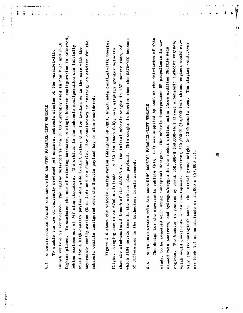
4.5
SU
BSO
NIC
--ST
AG
ED
SIN
GL
E
AIR
-BR
EA
TH
ING
B
OO
STER
PA
RA
LL
EL
-LIF
T
VE
HIC
LE
To
en
ab
le t
he
use
of
cu
rre
ntl
y p
rod
uce
d je
t e
ng
ine
s,
sub
son
ic s
tag
ing
of
the
pa
rall
el-
lift
lau
nc
h v
eh
icle
is c
on
sid
ere
d.
Th
e e
ng
ine
se
lec
ted
is t
he
F-1
00
cu
rre
ntl
y u
sed
i
n t
he
F-1
5 an
d F
-16
fig
hte
r p
lan
es.
T
o *
xax
imiz
e th
e u
se o
f e
xis
tin
g h
ard
wa
re,
a si
ng
le-b
oo
ste
r c
on
fig
ura
tio
n i
s s
ele
cte
d,
mak
ing
max
imum
u
se o
f 7
47
win
g s
tru
ctu
re.
Th
e o
rbit
er
in
th
e s
ub
son
ic c
on
fig
ura
tio
n w
as
init
iall
y
siz
ed
fo
r a
hig
h-d
en
sity
p
ay
loa
d
and
s
ide
lo
ad
ing
ra
the
r th
an
to
p
loa
din
g a
s is
th
e c
ase
wit
h t
he
sup
ers
on
ic c
on
iig
ura
tio
n
(Sec
. 4
.6)
and
th
e S
hu
ttle
. F
or
co
nsi
ste
nc
y i
n c
os
tin
g,
an
orb
ite
r fo
r th
e
sub
son
ic v
eh
icle
co
nfi
gu
red
wit
h t
he
Sh
utt
le p
ay
loa
d bay is
als
o c
on
sid
ere
d.
Fig
u?:e
4-
6 sh
ow
s th
e v
tl~
icle
co
nfi
gu
rati
on
(d
esi
gn
ed
b
y G
RC
), w
hic
h
use
s p
ara
lle
l-li
ft
bo
os
ter
flig
ht.
S
tag
ing
oc
cu
rs at
ti70
0 m
alt
itu
de
..I
2
50
fp
s (
Mac
h 0
.8),
o
nly
sli
gh
tly
gre
ate
r v
elo
cit
y
tha
n
the
sle
d-a
ss
isir
d
lau
nch
of
tlrc
? S
ST
O-I
iir)
. T
he
init
ial
ve
hic
le w
eig
ht
is 1
37
1 m
etr
ic
ton
s,
of
wh
ich
1
10
4 m
etr
ic
Lor
is is
th
e o
rbit
er
plu
s p
ay
loa
d.
Th
is w
eig
ht
is h
ea
vie
r th
an
th
e S
STO
-HTO
b
ec
au
se
of
dif
fere
nc
es
in
th
e
tec
hn
olo
gy
le
ve
ls a
ssu
med
.
4.6
SU
PER
SON
IC-S
TA
CE
D
'LW
N
AIK
-BR
EA
TH
ING
B
OO
STER
PA
RA
LL
EL
-LIF
T
VE
HIC
LE
Th
e d
esi
gn
fo
r th
e su
pe
rso
nic
vs
hic
le
(Fig
. 4-
7)
was
su
pp
lie
d b
y
LaR
C a
t th
e i
nit
iati
on
of
this
stu
dy
, to
be
co
mp
ared
wit
h o
the
r c
on
ce
ptu
al
de
sig
ns.
T
he
ve
hic
le i
nc
orp
ora
tes
RP
pro
pe
lla
nts
in
un-
man
ned
twin
b
oo
ste
rs,
and
hy
dro
gen
/ox
yg
en
in t
he
ro
ck
et
orb
ite
r u
sin
g t
hre
e m
od
ifie
d S
hu
ttle
mai
n
engines.
The boos1 e
l- is
yo
wr-
red
by
e i ~
I)L
35
0,00
0-N
(8
0,0
00
-lb
f)
thru
st
sup
ers
on
ic
turb
oje
t e
ng
ine
s,
wl~
ich
wo
uld
c
on
sti
tute
a
new
d
ev
elo
pm
en
t.
Ex
isti
ng
220
,000
-N
(53
,00
0-l
bf)
th
rus
t e
ng
ine
s c
ou
ld p
ro-
vid
e t
he
te
cim
olo
gic
i4l
bil
se.
'I'l
~c i
nit
ial
gro
ss w
eig
ht
is 1
28
5 m
etr
ic
ton
s.
Th
e s
tag
ing
co
nd
itio
ns
are
Mac
h 3.
5 a
t a
n a
ltit
ud
e o
t 1
8,0
00
m
(5
7,0
00
f
r)
.
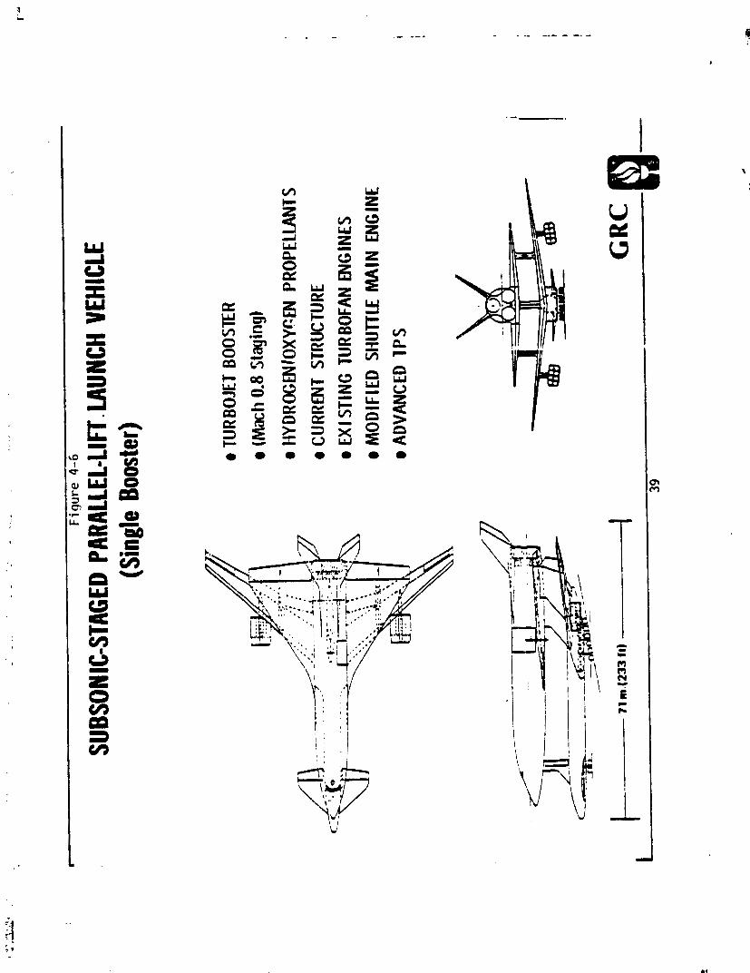
(Sin
gle
Boos
ter)
8 T
URBO
JET
BOOS
TER
e (
mh
0.8 S
tagi
ng)
e tlY
DRO
GEN
IOXY
WU
PROP
ELLA
NTS
8 C
URRE
NT S
TRUC
TURE
e EX
I STI
NG T
URBO
FAN
ENG
INES
a
MO
DIF
IED
SHU
rCLE
MA
IN E
NGIN
E m
ADVA
NCED
IP
S

.-
Fig
ure
4-7
SUPE
RSON
IC-S
TAGE
D PA
RALL
EL-L
IFT L
AUNC
H VE
HICL
E (T
win
Boos
ter)
0 HY
DRO
GEN
-OXY
GEN
O
RBIT
ER P
ROPE
LLAN
TS
0 C
URRE
NT S
TRUC
TURE
e A
I R-B
REAT
HING
, RP
V-TY
PE
BOO
STER
S
0 N
EW S
UPER
SON
lC T
UR B
OJf
3 LV
GIN
E
6 A
DVAN
CED
TPS
0 M
OD
IFIE
D S
HUTT
LE M
AIN
EN
GIN
ES

4.7
AIR
-BR
EATH
LNG
B
OO
STER
H
YPE
RSO
NIC
-STA
GED
V
EII
ICL
L
Th
e sc
ram
jet-
po
wer
ed
bo
ost
er
(Pig
. 4-
8)
use
s tu
rbo
jet
pro
pu
lsio
n
to t
ax
i,
tak
e o
ff,
accele
rate
to s
cra
mje
t ta
ke
ov
er
spe
ed
, an
d
fly
bac
k.
A
du
al-m
od
e sc
ram
jet
(su
bso
nic
an
d s
up
ers
on
ic c
am
bu
stio
n)
is a
ssu
med
f
or
pri
ma
ry p
rop
uls
ion
. T
he
six
tee
n 350,000-N c
las
s t
urb
oje
t are
sim
ila
r to
th
ose
use
d
for
the
su
pe
rso
nic
pa
rall
el-
lift
b
oo
ste
rs.
Gro
ss w
eig
ht
is 1
04
9 m
etr
ic
ton
s,
of
wh
ich
th
e o
rbit
er
co
ns
titu
tes
21
6 m
etr
ic
ton
s.
An
aly
sis
of
the
sc
ram
jet
bo
ost
er
ind
icate
s tb
t t
he
de
cre
asi
ng
th
rus
t c
oe
ffic
ien
t a
t th
e M
ach
nu
mb
er
ch
ara
cte
ris
tic
of
scra
mje
ts is
mo
re
of
a
lim
itin
g f
ac
tor
on
sta
gin
g M
ach
nu
mb
er
tha
n i
s s
pe
-
cif
ic i
mp
uls
e.
Th
e b
oo
ste
r h
as
a
scra
mje
t c
ap
ture
are
a e
qu
al
to a
bo
~t
o
ne
-te
nth
th
e a
ero
dy
na
mic
win
g
refe
ren
ce
are
a.
It a
pp
ea
rs t
o b
e q
ui
~c
d
iff
icu
lt t
o a
ch
iev
e a
h
igh
er
rati
o,
at
lea
se
for
inte
gra
ted
ve
hic
le/p
rop
uls
ion
co
nc
ep
ts.
Co
nse
qu
en
tly
, a
d
rag
co
eff
icie
nt
of
0.0
20
0
tra
ns
late
s i
nto
a
co
eff
i-
cie
nt
of
0.2
00
w
hen
refe
ren
ce
d
to t
he
ca
ptu
re a
rea
. A
bove
a
bo
ut
Mac
h 1
0 o
r p
erh
ap
s lb
ch
12
, th
e
thru
st
av
ail
ab
le a
bo
ve
dra
g r
eq
uir
em
en
ts is
li
ke
ly t
o b
e m
arg
ina
l fo
r a
cc
ele
rati
on
an
d c
lim
b.
Th
is
de
sig
n h
as
a
sta
gfn
g M
ach
nu
mb
er
of
10
.
4.8
SU
BSO
NIC
-STA
GED
T
WIN
AIR
-BR
EATH
ING
B
OO
STER
P
AR
AL
LE
L-L
Im
VE
HIC
LE
The
a
dv
an
tag
e o
f tw
in
bo
ost
ers
ov
er
a
sin
gle
bo
ost
er
is i
n d
evel
op
men
t c
os
t a
nd
th
e c
os
ts o
f
sup
po
rt f
ac
ilit
ies
. T
he
ve
hic
le d
esi
gn
(F
ig.
4-9
) w
as
av
ail
ab
le o
nly
ia
te i
n t
his
itu
dy
, a
ad
he
nc
e
is c
on
sid
ere
d o
nly
in
th
e c
os
t a
na
lyse
s (S
ec.
7).
It i
s n
ote
d,
tho
ug
h,
tha
t re
lati
ve
to
th
e s
ing
le-
bo
ost
er
de
sig
n
the
use
of
Ro
lls
Ro
yc.
R
B21
1-52
4B
en
gin
es
de
cre
ase
s fu
el
con
sum
pti
on
an
d
inc
rea
se
s
the
ca
pa
bil
ity
fo
r e
xte
nz
ed
ra
ng
e o
pe
rati
on
s,
de
sp
ite
th
e h
ea
vie
r e
ng
ine
we
igh
t.

Fig
ure
4-8
HYPE
RSON
IGST
AGED
AIR
-BRE
ATHI
NG T
WO-
STAG
E LA
UNCH
VEHI
CLE
e TU
RBOJ
ET P
iU S
SCRA
MJE
T BO
OSTE
R
a (M
ach
10 S
tagi
ng)
a AL
L HY
DRO
GEN
IOXY
GEN
PR
OPEL
LANT
S a
ADVA
NCED
STR
UCTU
RE
e AD
VANC
ED S
UPER
SO
NIC
TURB
OJET
a
ADVA
NCED
SCR
AMJE
T e
MO
D IF
1 ED
SHUT
TLE
MA
IN E
NGIN
E a
ADVA
NCED
TPS
GR
C
I
42


4.9
V
EH
ICL
E
WEI
GH
TS
The
w
eig
ht
bre
akd
ow
ns
for
the
se
ve
n c
an
did
ate
ve
hic
les
are
sho
wn
in
Fig
. 4
-10
, a
nd
de
tail
ed
we
igh
t st
ate
me
nts
fo
r a
ll v
eh
icle
s a
re i
n A
pp
end
ix A
. T
he
syst
em
dry
we
igh
t is
a b
ett
er
ind
ica
tor
of
co
st
tha
n i
s t
he
to
tal
syst
em
we
igh
t.
As
sta
gin
g M
ach
nu
mb
er
inc
rea
se
s,
the
in
cre
as
e i
n b
oo
ste
r w
eig
ht
is m
ore
th
an
co
mp
ensa
ted
by
the
re
du
cti
on
in
orb
ite
r w
eig
ht,
re
su
ltin
g
in a
n o
ve
rall
de
cre
ase
in
to
tal
syst
em
we
igh
t a
t la
un
ch
.
The
a
pp
are
nt
dis
cre
pa
nc
y b
etw
een
th
e s
ub
son
ic-s
tag
ed
o
rbit
er
and
th
e s
led
-la
un
ch
ed
o
rbit
er
(th
eir
we
igh
ts a
re c
om
pa
rab
le)
is d
ue
to t
he
ad
van
ced
s
tru
ctu
re u
sed
in
th
e s
led
-as
sis
ted
v
eh
icle
co
mp
ared
to t
he
cu
rre
nt-
str
uc
ture
te
ch
no
log
y o
f th
e s
ub
son
ic v
eh
icle
. T
he
Bo
ein
g-d
esig
ned
sl
ed
-la
un
ch
ed
ve
hic
le a
lso
em
plo
yed
a
s
lig
htl
y l
igh
ter,
h
ot-
str
uc
ture
T
PS
com
par
ed
to a
n
on
-me
tall
ic
reu
sa
ble
su
r-
fac
e i
ns
ula
tio
n (
RS
I)
on
th
e s
ub
son
ic v
eh
icle
. T
he
Ma
rtin
VTO
si
ng
le-s
tag
e-t
o-o
rbit
v
eh
icle
als
o
use
s ad
van
ced
s
tru
ctu
re b
ut
wit
h R
SI.
Fo
r th
e a
ir-b
rea
thin
g
ve
hic
les
, th
e
tota
l d
ry w
eig
ht
inc
rea
se
s s
low
ly w
ith
sta
gin
g M
ach
nu
mb
er,
and
a
ll
air
-bre
ath
ing
v
eh
icle
s a
re h
ea
vie
r th
an
th
e s
ing
le-s
tag
e-t
o-o
rbit
v
eh
icle
s.
Th
e d
ry w
eig
ht
of
sub
son
ic a
nd
su
pe
rso
nic
air
-bre
ath
ing
sy
ste
ms
is a
pp
rox
ima
tely
tr
iple
th
at
of
the
sin
gle
-sta
ge
-to
-
orb
it v
eh
icle
s d
ue
in
la
rge
pa
rt
to d
iffe
ren
t a
ssu
mp
tio
ns
reg
ard
ing
str
uc
ture
te
ch
no
log
y a
nd
en
gin
e
we
igh
t.
4.1
0
FL,I
GH
T PA
RA
MET
ER
DATA
The
m
ain
fl
igh
t p
ara
me
ters
a
ss
oc
iate
d w
ith
ea
ch
la
un
ch
ve
hic
le a
re s
um
mar
ized
in
Fig
. 4-
11.
The
tw
o h
yp
ers
on
ic
syst
em
s (t
he
all
-ro
ck
et,
C
, an
d
the
air
-bre
ath
ing
b
oo
ste
r,
F)
ac
tua
lly
sta
ge
at
ap
pro
xim
ate
ly e
qu
iva
len
t e
ne
rgy
co
nd
itio
ns-
-th
e
Mac
h n
um
ber
sh
own
for
the
ro
ck
et
bo
os
ter
is d
ue
to
low
er
so
nic
ve
loc
ity
at
the
hig
h s
tag
ing
alt
itu
de
.

Fiq
ure
4-1
0
LAUN
CH VE
HICL
E W
EIGH
T DA
TA
29,0
00-k
g (6
5,00
0-lb
m)
Paylo
ad
92.5
x 18
5-km
(5
0 x
100 n
mi),
28
" Or
bit
VE
IiIC
I-E
OP
TIO
NS
-
ST
AG
ING
S
STO
S
STO
T
S
TS
15
TS
T
AK
EO
FF
V
TO
H
TO
H
TO
~
+ro
I I
TO
H
TO
P
RO
PU
LS
ION
n
R
R/R
TJ
/R
TJ/
n
T.1-
SJI
R
ST
AG
ING
10
0.8
3.5
lo+
MACH N
O.
GR
OS
S W
T
1207
1250
1050
1371
1285
1049
(2660)
(2750)
(23 14)
(3022)
(2833)
(2313)
OR
BIT
ER
WT
1207
1250
216
1 104
824
216
(2660)
(2750)
(476)
(2433)
(1817)
(476)
BO
OS
TER
WT
-
249"
834
267
4 GO
833
(549)
(1 838)
(589)
(1010)
(1837)
TO
TA
L D
RY
WT
114
99
19G
330
35 1
422
(251 1
(218)
(432)
(741)
(775)
(930)
All
wei
gh
ts WOO.
"Sle
d w
eig
ht not
i~lc
lud
ed in g
ross
.

Fig
ure
4-1
1
FLIG
HT P
ARAM
ETER
DAT
A
A
B
C
D
E
F
STA
GIN
G
. SS
TO
SSTO
TS
TS
TS
TS
TA
KE
OFF
V
TO (H
h)
tITO
H
TO
HTO
H
TO
llTO
P
RO
PU
LSIO
N
fl
n R
/R
TJ/
n TJ
/R
TJ-S
C/R
STA
GIN
G C
ON
OlT
lON
S
MA
CH
NO
. 0
VE
LOC
ITY
(m
hec)
0
ALT
ITU
DE
(m
) 0
DY
NA
ME
PR
ESSU
RE
(N/m
2)
0
MAX
. D
YN
AM
IC P
nES
SU
RE
(~
Irn
2)
35,0
00
WIN
G L
OA
DIN
GS
(~
/m2
) BO
OST
ER A
T T
AK
EO
FF
- O
RB
ITE
R A
T T
AK
EO
FF
27,3
00
OR
BIT
ER
AT
STA
GIN
G
- O
RB
ITE
R A
T LA
ND
ING
31
00
THR
US
T/W
EIG
HT
TAK
EO
FF
STA
GIN
G
AZ
IMU
TH
CA
PA
BIL
ITY
36
00
OFF
SE
T C
AP
AB
ILIT
Y (
km)
93
GR
C
4 6


5
TECH
NO
LOG
Y
ASS
ESSM
ENT
An
ass
ess
me
nt
of
the
key
te
ch
no
log
y n
ee
ds
for
ea
ch
la
un
ch
ve
hic
le i
s p
erfo
rmed
u
sin
g a
met
ho
do
log
y
pre
vio
usl
y d
ev
elo
pe
d
for
NA
SA
Ile
ad
qu
art
ers
,l1
an
d
ex
te~
.de
d h
ere
to
in
clu
de
a
tec
hn
olo
gy
de
fic
ien
cy
co
st
fac
tor
(TD
CF
).
Th
is f
ac
tor
is u
sed
to
de
riv
e a
te
ch
no
log
y d
efi
cie
nc
y c
os
t th
at
ca
n b
e
add
ed
to t
he
tra
dit
ion
al
RD
TdE
co
sts
. T
his
te
ch
no
log
y
rea
din
es
s a
sse
ssm
en
t m
eth
od
olo
gy
ha
s p
rov
ed
us
efu
l fo
r g
en
era
tin
g f
utu
re t
ec
hn
olo
gy
pro
gra
m n
ee
ds
and
fo
r in
dic
ati
ng
th
e t
ec
hn
olo
gic
al
ris
k
inh
ere
nt
in
pro
po
sed
fl
igh
t p
rog
ram
s.
In o
rde
r to
fo
rma
liz
e a
te
ch
no
log
y r
ea
din
es
s m
eth
od
olo
gy
, it i
s n
ec
ess
ary
to
es
tab
lis
h a
mea
sure
by
w
hic
h
the
sta
tus
an
d
ob
jec
tiv
es
of
tec
hn
olo
gy
re
ad
ine
ss
ca
n b
e d
efi
ne
d.
Th
e te
ch
no
log
y
rea
din
es
s e
va
lua
tio
n c
rit
er
ia a
re s
how
n in
Fig
. 5
-1
as
dif
fere
nt
lev
els
of
rea
din
es
s,
us
ing
a
sev
en
-le
ve
l s
ca
le (
wh
ich
ha
s su
bse
qu
en
tly
bee
n
use
d
by
OA
ST,
the
Off
ice
of
Ae
ron
au
tic
s an
d
Sp
ac
e
Tec
hn
olo
gy
, N
ASA
H
ea
dq
ua
rte
rs,
to a
ss
ist
in e
sta
bli
sh
ing
te
ch
no
log
y n
ee
ds
for
adv
ance
d
pro
gra
ms,
and
te
ch
no
log
y
rea
din
es
s e
sti
ma
tes
fo
r p
rop
ose
d
spa
ce
pro
gra
ms)
. E
ach
e
lem
en
t o
f a
p
rop
ose
d
syst
em
ca
n b
e e
va
lua
ted
to
de
term
ine
its
cu
rre
nt
sta
tus
an
d
the
eff
ort
re
ma
inin
g b
efo
re i
nc
orp
ora
tio
n i
nto
a
new
p
rog
ram
.
Alt
ho
ug
h
the
met
ho
do
log
y r
eq
uir
es
su
bje
cti
ve
in
pu
ts
(re
pre
se
nta
tiv
e o
f a
c
las
s o
f d
ec
isio
n
too
ls c
ate
go
riz
ed
as
a D
elp
hi
pro
ce
ss),
it h
as
be
en
sh
own
tha
t th
e p
roc
ess
of
as
sig
nin
g c
urr
en
t
sta
tus
an
d
req
uir
ed
sta
tus
fo
r te
ch
no
log
y
rea
din
es
s i
s c
on
du
civ
e t
o a
n o
ve
rall
co
nse
nsu
s.
A
tec
h-
no
log
y a
sse
ssm
en
t in
vo
lve
s m
any
de
cis
ion
s;
larg
e d
isa
gre
em
en
ts i
n a
ny
s
ing
le d
ec
isio
n d
o n
ot
sig
nif
ica
ntl
y c
ha
ng
e t
he
ov
era
ll r
es
ult
s.


5.1
METHODOLOGY FOR ESTIMATING TECHNOLOGY DEFICIENCY COSTS
Items requiring equivalent gains in technology readiness levels may not be achievable with the
same degree of effort.
To account for differences in effort, technology risk criteria have been
established and are shown in Fig. 5-2. The numerical values of risk (3, 6, and 9) have been select-
ed such that risk and the gain in readiness level have approximately the same weighting in determining
technology readiness.
Several factors that are useful in evaluating the cost associated with technical risk are de-
fined in Fig. 5-3.
The technology deficiency index (TDI)
is the gain in technology level required to
achieve readiness (difference between levels in Fig. 5-1) times the risk, summed over the individual
elements of the system. In comparing competing alternatives, the TDI indicates the relative risk to
be expected due to technol~gy deficiencies.
The technology deficiency factor (TDF) indicates the d
eg~re d
l technology deficiency (a normal-
jzed value of the TDI).
One minus the TDF id an indication of how near technology readiness is to
being achiever.
The TDF is incorporated into the technology deficiency cost factor (TDCF), which
is used
to estimate the cost associated with technology uncertainty in the development of a new
system.
RDTCE cost estimates are multiplied by the TDCF to account for technology risk.
Additional effort is needed to define more precisely an appropriate cost factor to account
for technology deficiencies at program initiation if more accurate program cost estimates are to
be made.
It is hoped that the impact of technology deficiencies on program cost as indicated in
this analysis is sufficient to stimulate additional work.

Fig
ure
5-2
TECH
NOLO
GY R
lSK
ASSE
SSM
ENT
CRIT
ERIA
TE
CH
NO
LOG
Y E
XIS
TS
AN
D H
AS
BE
EN
DE
MO
NS
TR
AT
ED
IN
OT
tiE
R E
QU
IPM
EN
T
LOW
A
LT
ER
NA
TIV
ES
Afl
E B
EIN
G D
EV
ELO
PE
D,
AL
TH
OU
GH
TH
EY
(3)
AR
E N
OT
YE
T P
RO
VE
N
0
PA
RA
LL
EL
DE
VE
LOP
ME
NT
S A
RE
PO
SS
IBLE
LE
VE
L O
F R
ISK
41 -
TE
CH
NO
LOG
Y D
OE
S N
OT
EX
IST
AN
D M
US
T B
E D
EV
EL
OP
ED
HIG
H
AL
TE
RN
AT
IVE
S D
O N
OT
EX
IST
(9
) P
AR
AL
LE
L D
EV
ELO
PM
EN
TS
AR
E N
OT
PO
SS
IBLE
TE
CH
NO
LOG
Y E
XIS
TS
BU
T H
AS
NE
VE
R B
EE
N D
EM
ON
ST
RA
TE
D
AL
TE
RN
AT
IVE
S A
RE
PO
SS
IBLE
BU
T A
RE
CO
ST
LY IN
TE
RM
S O
F
ME
DIU
M
DO
LL
AR
S
(6)
RE
SO
UR
CE
S A
ND
SC
HE
DU
LE A
RE
MA
RG
INA
L F
OR
PA
RA
LL
EL
D
EV
ELQ
PM
EN
TS
BU
T P
AR
AL
LE
L D
EV
EL
OP
ME
NT
S A
RE
ST
ILL
P
OS
SIB
LE

Fig
ure
5-3
TECH
NOLO
GY R
EADI
NESS
ASS
ESSM
ENT
FACT
ORS
- A
- TE
CHNO
LOGY
DEF
I c I E
NC
Y
COST
FA
CTO
R (TDC
F) -
.1 - TDF
GR
C
52

5.2
TE
CHN
OLO
GY
D
EFI
CIE
NC
Y
CO
STS
Th
e d
ata
use
d
in t
he
te
ch
no
log
y r
ea
din
ess
an
aly
sis
ar
e p
rese
nte
d
in A
pp
end
ix
B,
and
th
e
res
ult
s o
f th
e a
ssess
mefi
t are
su
mm
ariz
ed
in F
igs.
5-
4 an
d
5-5.
A
s e
xp
ec
ted
, th
e s
ub
son
ic p
ara
lle
l-
li
ft
ve
hic
le h
as
the
lo
we
st
TD
I.
On
ly
the
TPS
an
d
the
in
tern
ali
ze
d c
on
tou
r-c
on
fig
ure
d
pro
pe
lla
nt
tan
ks
(in
clu
din
g a
c
ryo
ge
nic
we
t w
ing
) a
pp
ea
r to
re
qu
ire
sig
nif
ica
nt
tec
hn
olo
gy
ad
va
nc
es.
T
he TDI
Inc
rea
ses
rap
idly
wit
h s
tag
ing
Mac
h nu
mbe
r b
ec
au
se o
f in
cre
ase
d
the
rma
l p
rote
cti
on
re
qu
ire
me
nts
--
the
scr
amje
t-p
ow
ered
b
oo
ste
r re
pre
se
nts
ve
ry a
dv
ance
d
tec
hn
olo
gy
, as
it i
s s
imil
ar
to a
se
con
d
orb
ite
r,
bu
t c
om
pli
ca
ted
by
a
ir-b
rea
thin
g
pro
pu
lsio
n r
eq
uir
em
en
ts.
It
is i
nte
res
tin
g t
o n
ote
th
at
the
sle
d-a
ssis
ted
SS
TO
ve
hic
le h
as
a
hig
he
r T
DI
tha
n e
ith
er
the
VTO S
STO
o
r t
he
su
pe
rso
ntc
-sta
ge
d
pa
rall
el-
lift
v
eh
icle
. T
he
ho
t m
eta
l T
PS
and
th
e a
dv
ance
d
str
uc
ture
(c
ryo
ge
nic
we
t w
ing
, s
led
as
sis
t)
of
the
HTO
SSTO
re
pre
se
nts
hig
he
r te
ch
no
log
ica
l ri
sk
th
an
th
e d
evel
op
men
t o
f la
rge
jet
en
gin
es
for
the
su
pe
rso
nic
pa
rall
el-
lift
v
eh
icle
.
Th
e re
lati
ve
ra
nk
ing
of
the
la
un
ch
ve
hic
le c
an
did
ate
s b
ase
d
on
TD
CF
pa
rall
els
th
e r
an
kin
g
ba
sed
o
n t
k,e
TD
I,
as
is
to b
e e
xp
ec
ted
. T
he
hig
he
r th
e t
ec
hn
olo
gy
ris
k,
the
hig
he
r th
e I
DZ
F
sho
uld
be.
5.3
KEY
TECH
NO
LOG
Y
NEE
DS
Th
e e
va
lua
tio
n o
f th
e T
DI
for
ea
ch
ele
me
nt
in t
he
la
un
ch
ve
hic
le p
rov
ide
s a
n e
asy
qu
an
tita
tiv
e
met
ho
d
for
de
term
inin
g
tec
hn
olo
gy
n
eed
s.
A TD
L v
alu
e o
f 1
8 o
r g
rea
ter
was
a
rb
itr
ar
ily
se
lec
ted
fo
r d
ete
rmin
ing
key
tec
hn
olo
gy
n
ee
ds,
w
hic
h a
re
sho
wn
in F
ig.
5-6.
The e
va
lua
tio
n s
ho
ws
tha
t a
fu
lly
re
usa
ble
ad
van
ced
T
PS
co
mp
ati
ble
wit
h s
ch
ed
ule
d m
ain
ten
an
ce
was
th
e o
nly
key
te
ch
no
log
y
tha
t w
as
req
uir
ed
by
ev
ery
la
un
ch
ve
hlc
le o
pti
on
. T
he
hy
pe
rso
nic

1 ORBITER (330) SLED "11
BOOSTER (402) 1

VEHI
CLE
OPT
IONS
r
TEC
t IN OL
OG Y
1.
I4
1.12
1.06
1.08
1.15
DEFI
C IE
NCY
GR
C
55
STAG
S NG
TAkE
OFF
PRO
PULS
ION
STA
GIN
GM
AC
HN
O.
SSTO
SS
TO
TS
TS
TS
TS
VTO
t I
T0
IGO
11
10
HTO
t I
T0
R R
RIR
TJli?
TJ
IR
TJ-S
JIR
-
-
0.8
3.5
10+
--
10
--

X X X
X
X
X X X
X X
LI
0

scra
mje
t-p
ow
ered
b
oo
ste
r h
as
the
mo
st
ne
ed
s,
and
th
e s
ub
son
ic t
urb
oje
t-p
ow
ere
d
bo
ost
er
the
few
est
. T
he
foll
ow
ing
ad
dit
ion
al
po
ints
ar
e n
ote
d:
1.
Al
l h
ori
zo
nta
l ta
ke
off
v
eh
icle
s b
en
efi
t s
ign
ific
an
tly
if
th
ey
us
e a
cry
og
en
ic
wet
w
ing
.
Th
e sc
ram
jet
pro
pu
lsio
n
syst
em
is i
n a
ve
ry
ea
rly
sta
ge
of
dev
elo
pm
ent,
re
qu
ire
s
new
te
st
fa
cil
itie
s,
and
is
ex
tre
me
ly
se
ns
itiv
e t
o v
eh
icle
co
nfi
gu
rati
on
an
d
str
uc
tura
l w
eig
ht.
Bo
th
of
the
sin
gle
-sta
ge
v
eh
icle
s
req
uir
e s
ign
ific
an
t im
pro
vem
ents
in
ad
van
ced
ma
teri
als
, s
tru
ctu
res
, a
sse
mb
ly,
and
m
an
ufa
ctu
rin
g
ca
pa
bil
itie
s.
Th
e d
evel
op
men
t o
f ne
w
tes
t h
ard
wa
re
to a
ssis
t in
qu
ali
ty c
on
tro
l d
uri
ng
man
u-
fac
turi
ng
is a
n
imp
ort
an
t a
rea
th
at
is o
fte
n o
ve
rlo
ok
ed
.

6
CO
ST
ASS
ESSM
ENT
The
mo
del
de
ve
lop
ed
by
A
ero
spac
e ~
or
po
ra
tio
n'~
to
ev
alu
ate
co
sts
of
Ea
rth
-to
-orb
it
and
o
rb
ita
l
tra
ns
fer
ve
hic
les
is
use
d
in t
his
stu
dy
. B
ased
o
n
sub
syst
em
co
st-e
stim
ati
ng
re
lati
on
sh
ips
, th
e
mo
del
g
en
era
tes
PDT
&E
, in
ve
stm
en
t,
op
era
tio
ns,
an
d m
ain
ten
an
ce
c
os
t e
stim
ate
s.
6.1
L
IFE
CY
CLE
C
OST
S
Th
e l
if
e c
yc
le c
os
t e
stim
ate
s fo
r e
ac
h l
au
nc
h v
eh
icle
co
nsi
de
red
in
th
e s
tud
y a
re s
ho
wn
in
Fig
. 6-
1.
Th
e to
tal
pro
gra
m
co
sts
fo
r v
eh
icle
s A
, B
, D
, E
, an
d
G
ar
e f
or
all p
rac
tic
al
pu
rpo
ses
the
sam
e,
wh
ere
as
bo
th
the
hy
pe
rso
nic
tw
o-s
tag
e la
un
ch
ve
hic
les
(C
an
d
F)
are
sig
nif
ica
ntl
y m
ore
co
stl
y.
Th
e H
TO
sin
gle
-sta
ge
-to
-orb
it
is t
he
le
as
t e
xp
en
siv
e v
eh
icle
by
a
n
arro
w m
arg
in.
Fo
r tw
o-
sta
ge
ve
hic
les
, h
igh
er
sta
gin
g n
um
ber
s le
ad
to
lo
we
r o
rbit
er
co
sts
, b
ut
hig
he
r b
oo
ste
r c
os
ts.
Fig
ure
6-1
sh
ow
s th
at
alm
ost
a
bil
lio
n d
oll
ars
in
RD
T&E
co
sts
ca
n b
e
sav
ed
by
de
ve
lop
ing
th
e
Lan
gle
y-d
esig
ned
su
bso
nic
tw
in b
oo
ste
r v
eh
icle
in
ste
ad
of
the
la
rge
r s
ing
le b
oo
ste
r.
Inv
est
me
nt
co
sts
do
no
t ch
ang
e s
ign
ific
an
tly
bet
wee
n
sin
gle
an
d
twin
bo
ost
ers
, an
d
the
le
arn
ing
cu
rve
plu
s l
ow
er
fir
st
un
it
co
st
ten
ds
to c
om
pen
sate
fo
r th
e l
arg
er
num
ber
of
twin
bo
ost
ers
re
qu
ire
d.
Th
e o
ve
rall
res
ult
in
go
ing
fro
m a
s
ing
le t
o a
tw
in b
oo
ste
r is
to
re
du
ce
pro
gra
m
co
sts
by
ap
pro
xim
ate
ly S
IB.
Wit
ho
ut
the
in
clu
sio
n o
f te
ch
no
log
y d
efi
cie
nc
y c
os
ts,
the
su
pe
rso
nic
pa
rall
el-
lift
v
eh
icle
(E)
is l
ess e
xp
en
siv
e t
ha
n
eit
he
r su
bso
nic
ve
hic
le
(D
and
G
).
Wit
h
the
in
clu
sio
n o
f te
ch
no
log
y d
efi
cie
nc
y
co
sts
, th
ou
gh
, th
e t
win
-bo
ost
er
sub
son
ic p
ara
lle
l-li
ft
ve
hic
le
(G)
is l
ess e
xp
en
siv
e.
Ho
wev
er,
the
dif
fere
nc
es
are
re
lati
ve
ly s
ina
ll a
nd
a
re n
ot
sig
nif
ica
nt:
be
ca
use
of
the
un
ce
rta
inty
of
the
co
st
est
ima
tes.
A
pp
end
ix
C
sho
ws
de
tail
ed
co
st
da
ta
for
ea
ch
la
un
ch
ve
hic
le.

5-VE
H I C
LE F
LER
10-Y
R O
PERA
TI O
N S
4197
FLI
GHT
S
Fig
ure
6-1
LIFE
CYC
LE C
OST
J
A B
C 0
E I--
G
STAG
l NG
S ST
0 SS
TO
TS
TS
TS
TS
TS
TAKE
OFF
VTO
HTO
\IT0
HTO
HT
O HT
O
HTO
PRO
PULS
ION
R R
RIR
TJ IR
TJ
IR
TJ-S
JIR
TJIR
( )
incl
udes
cos
t ass
ocia
ted
with
tech
nolo
gy r
isk.
*
Subs
onic
Win
Boo
ster
. G
RC

In order to provide a rough indication of the accuracy of the cost models, operations costs
per flight for the current Shuttle are derived using Boeing, Martin, and Aerospace models (see
Jig.
62
).
Martin and Boeing estimates agree with current average costs quoted for the Shuttle,
whereas the Aerospace model appears to be in agreement with the projected
low
user costs given in
two NASA publications. l3*l4 The differences among the estimates are due primarily to differences
in manpower requirements--the Aerospace values assume a manpower forecast representative of mature
operations. Also, the RDT&E costs generated by the Aerospace model appear high compared to the costs
estimated for the Shuttle. However, when actual R
DT&
E costs are available, the Aerospace model
estimates may well prove to be more realistic since traditionally RDTdE projected ccsts have been
underestimated.
The Martin model is based on manpower time estimates, which are converted to costs using
labor rates, whereas the Aerospace model is based on subsystem cost projections plus operations and
mzintenance manning estimates.
Differences between the Martin and Aerospace models in estimating
investment and operations costs appear to be simply bookkeeping; some of the operations cost
associated with facilities in the Martin model are considered in the Aerospace model to be investment
costs.
6.2
MISSION MODEL FOR COST EVALUATION
The cost estimates presented in Fig. 6-1 are based on 10-year operations of a 5-vehicle
fleet capable of completing 4197 flights. The utilization rate for the vehicles is high compared
to that for the Shuttle because of two factors:
(1) a 1-day average mission duration (compared
to
a 14-day average mission duration for the Shuttle),
and
(2)
scheduled maintenance. A 1-day average
mission is proposed as realistic for these vehicles based on the mission assessment in which a new

I.
,
. -
I.
, .
, ,
. .
I/
.
- .
.
- .
- .
- . .
. .
- ..
.-
.. .- ~
. ..
. -
. .-
-. ..
. ."-
--.
..-. -
.
- F
igu
re 6-2
SHUT
TLE
COST
COM
PARI
SON
OPER
ATIO
NS C
OST
PER
FLIG
HT
MA
RT
IN"
AE
RO
SP
AC
E
CO
ST
EL
EM
EN
T
- P
RO
GR
AM
SU
PP
OR
T (G
RO
UN
D O
PE
RA
TIO
NS
, F
LIG
HT
OP
ER
AT
ION
S, &
PR
OG
RA
M R
ES
ER
VE
S)
- S
PA
RE
S
- S
RM
- E
XT
ER
NA
L T
AN
K
- E
NG
INE
S
- F
UE
L A
ND
PR
OP
EL
LA
NT
S
TO
TA
L
CO
ST
- K
SC
CIV
IL S
ER
VIC
E
- L
AU
NC
H O
PE
RA
TIO
NS
- F
LIG
HT
OP
ER
AT
ION
S (J
SC
) - n
EF
UR
BlS
HM
EN
T
- S
RM
- E
XT
ER
NA
L T
AN
K
- E
NG
INE
S
TO
TA
L
-
--
- O
PE
RA
TIO
NS
- SP
AR
ES
AN
D P
RO
PE
LL
AN
TS
-
RA
NG
E/B
AS
E S
UP
PO
RT
-
EX
PE
ND
AB
LE
HA
RD
WA
RE
T
OT
AL
'Bas
ed o
n 1
5-ye
ar O
pera
tions
, 10
16 'L
sunc
ties
GR
C
6 1
lau
nc
h v
eh
icle
in
th
e f
utu
re w
ou
ld
de
liv
er
ca
rgo
an
d/o
r p
ass
en
ge
rs
to a
li
mit
ed
nu
mb
er
of
de
sti
na
tio
ns
.
Sch
edu
led
ma
inte
na
nc
e a
pp
ea
rs t
o b
e m
ore
a
pp
rop
ria
te f
or
a
full
y r
eu
sab
le
lau
nc
h v
eh
icle
tha
n a
n a
s-y
ou
-go
m
ain
ten
an
ce
ph
ilo
sop
hy
as
so
cia
ted
wit
h a
p
art
iall
y r
es
ua
ble
la
un
ch
ve
hic
le s
uc
h
as
th
e S
hu
ttle
, w
her
e re
co
ve
ry a
nd
re
furb
ish
me
nt
op
era
tio
ns
are
re
qu
ire
d.
Fig
ure
6-3
p
res
en
ts a
ma
inte
na
nc
e s
ch
ed
ule
wh
ich
sp
an
s th
e e
nti
re o
pe
rati
on
al
li
ft
of
the
ve
hic
le.
It
is p
rop
ose
d
tha
t
af
ter
11
2 m
issi
on
s th
e o
rbit
er
wi
ll
un
de
rgo
an
en
gin
e c
han
geo
ut.
A
fte
r 4
48
mis
sio
ns
it i
s o
ve
r-
ha
ule
d,
and
a
fte
r t
wo
ov
erh
au
ls i
t is
re
tire
d.
Ov
erh
au
ls
and
e
ng
ine
ch
an
ge
ou
ts a
re
made
in c
en
tra
l-
ize
d m
ain
ten
an
ce
fa
cil
itie
s.
As
no
ted
in
Sec
. 2
.3,
turn
aro
un
d
tim
es
fo
r tw
o-s
tag
e
air
-bre
ath
ing
v
eh
icle
s a
re e
stim
ate
d
to
be
60
ho
urs
. S
imil
ar
turn
aro
un
d
tim
es
hav
e b
een
p
rop
ose
d
by
th
e M
art
in
Com
pany
f
or
th
e S
STO
-VTO
ve
hic
le,
and
th
e B
oei
ng
Com
pany
h
as
est
ima
ted
a
18
0-h
ou
r tu
rna
rou
nd
ti
me
for
the
SST
O-II
TO
. H
ow
ever
,
assu
min
g a
fu
lly
re
usa
ble
pro
tec
tio
n s
yst
em
is d
ev
elo
pe
d,
the
SST
O-H
TO
mig
ht
als
o a
ch
iev
e a
6
0-h
ou
r
turn
aro
un
d
tim
e.
So
as
no
t to
un
rea
lis
tic
all
y p
en
ali
ze
th
e S
STO
-HT
O,
a
60
-ho
ur
turn
aro
un
d ti
me
was
~
ss
um
ed
for
co
sti
ng
pu
rpo
ses.
Th
e m
issi
on
ca
pa
bil
ity
(F
ig.
6-4)
o
f e
ac
h
laa
nc
h v
eh
icle
is d
ete
rmin
ed
by
co
mb
inin
g t
he
mai
n-
* te
na
nc
e
sch
ed
ule
(in
clu
din
g u
nsc
he
du
led
ma
inte
na
nc
e, \ =
0
.95
),
a
ve
rag
e f
lig
ht
du
rati
on
, an
d
the
turn
aro
un
d
tim
e.
A
tota
l e
xp
ec
ted
ve
hic
le l
ife
tim
e o
f 5
93
2 d
ay
s (1
6.2
5
ye
ars
) is
pro
jec
ted
. T
he
mis
sio
n
fac
tor
(to
tal
num
ber
of
mis
sio
ns
div
ide
d b
y
ve
hic
le l
ife
tim
e)
is 0
.23
, co
mp
ared
to
ap
pro
xi-
ma
tely
0
.14
fo
r th
e S
hu
ttle
(n
ot
inc
lud
ing
ov
erh
au
l ti
me
).
Bas
ed
on
a m
issi
on
fa
cto
r o
f 0
.23
,
each
la
un
ch
ve
hic
le w
ou
ld
be
ca
pa
ble
of
83
9
mis
sio
ns
du
rin
g a
1
0-y
ear
op
era
tin
g p
eri
od
; o
r,
fo
r a
* Rep
rog
ram
mab
le
reli
ab
ilit
y,


fiv
e-v
eh
icle
fl
ee
t,
4197 m
issi
on
s c
ou
ld b
e f
low
n.
Com
pare
d to
cu
rre
nt
op
era
tio
na
l p
roje
cti
on
s
of
lau
nc
h v
eh
icle
dem
and,
420 m
issi
on
s p
er
ye
ar
is u
nre
ali
sti
c.
How
ever
, to
av
oid
d
isc
ussio
n a
bo
ut
the
va
lid
ity
of
sp
ec
ific
mis
sio
n m
od
els,
c
os
t co
mp
ari
son
s b
etw
een
th
e l
au
nc
h v
eh
icle
op
tio
ns c
on
-
sid
ere
d
in t
he
stu
dy
are
bas
ed
on
the
max
imum
p
ote
nti
als
of
the
la
un
ch
ve
hic
les,
wh
ich
pro
vid
e a
n
ind
ica
tio
n o
f th
e m
inim
um
co
st
pe
r f
lig
ht
tha
t m
ay
be
ac
hie
va
ble
wit
n
each
.
6.3
O
PER
ATIO
NS
CO
STS PER F
LIG
HT
A co
mp
aris
on
o
f e
stim
ate
d o
pe
rati
on
s c
os
ts p
er
flig
ht
is s
how
n in
Fig
. 6
-5,
ind
ica
tin
g t
ha
t
co
sts
pe
r fl
igh
t b
etw
een
$2.5M
and
$3
M
co
uld
b
e a
ch
iev
ed
wit
h a
fu
lly
re
usa
ble
la
un
ch
ve
hic
le.
The
low
er
est
ima
te c
orr
esp
on
ds
to t
he
tw
o-s
tag
e su
bso
nic
, p
ara
lle
l-li
ft
ve
hic
le a
nd
th
e h
igh
er
to s
ing
le-
sta
ge
ve
hic
les,
wit
h
the
tw
in b
oo
ste
r d
esi
gn
s in
th
e m
idd
le.
Th
e c
os
ts o
f th
e h
yp
ers
on
ic-s
tag
ed
ve
hic
les
(no
t p
ara
lle
l l
if
t)
are
hig
he
r,
and
p
rob
ab
ly
no
t c
om
pe
titi
ve
. C
ompa
red
to t
he
SSTO-VTO,
the
re
du
cti
on
in
orb
ite
r s
ize
fo
r a
tw
o-s
tag
e v
eh
icle
re
su
lts
in
sig
nif
ica
nt
pro
pe
lla
nt
co
st
sav
ing
s.
In t
he
ca
se o
f th
e S
STO
-HTO
v
eh
icle
, th
e s
led
as
sis
t in
cre
ase
s o
pe
rati
on
s c
os
ts t
o a
le
ve
l ju
st
abo
ve
tho
se f
or
the
su
bso
nic
and
sup
ers
on
ic p
ara
lle
l-li
ft
ve
hic
les.
The
e
lim
ina
tio
n o
f ex
pen
dab
le h
ard
ware
pro
vid
es
su
bs
tan
tia
l sa
vin
gs
rela
tiv
e t
o t
he
Sh
utt
le;
de
leti
ng
ju
st
the
so
lid
-ro
ck
et
bo
oste
rs a
nd
th
e e
xte
rna
l p
rop
ell
an
t ta
nk
ac
co
un
ts f
or
a
red
uc
tio
n
of
alm
ost
40
%.
The
man
nin
g
co
st
for
op
era
tio
ns a
nd
m
ain
ten
an
ce is
ab
ou
t e
qu
al
for
the
sin
gle
- an
d
two
-sta
ge
lau
nc
h v
eh
icle
s,
bu
t in
cre
ase
d
eff
icie
nc
y i
n g
rou
nd
cre
w a
nd
f
ac
ilit
ies
du
e 50
an
in
cre
ase
d
lau
nc
h r
ate
pro
vid
es
an
ad
dit
ion
al
33%
re
du
cti
on
. A
lto
ge
the
r it i
s e
stim
ate
d
tha
t a
fu
lly
re
usa
ble
lau
nch
ve
hic
le c
an
re
du
ce
man
pow
er
req
uir
em
en
ts b
y
ap
pro
xim
ate
ly
80
% c
om
par
ed
to t
ho
se
of
the
Sh
utt
le.
Com
pare
d to
a s
ing
le-s
tag
e-t
o-o
rbit
la
un
ch
ve
hic
le,
a
two
-sta
ge
pa
rall
el-
lift
v
eh
icle
eli
min
ate
s t
he
nee
d
for
a
lau
nc
h p
ad
, b
ut
req
uir
es
a c
om
par
able
e
xp
en
dit
ure
fo
r a
se
pa
rate
pro
pe
lla
nt-
se
rvic
e a
nd
as
sem
bly
fa
cil
ity
. A
co
mp
aris
on
of
man
nin
g
esti
ma
tes i
s s
how
n i
n F
ig.
6-6.
65

I
I'
I
m
Fig
ure
6-5
5-VE
HICL
E FL
EET
10-Y
EAR
OPE
RATI
ON S
41
97 F
LIG
HTS
OPER
ATIO
NS C
OST
PER
FLIG
HT
VEHI
CLE
OPT
IONS
STAG
ING
SS
TO
SSTO
TS
TS
TS
TS
TS
TA
KEOF
F VT
O
HT0
HT
O HT
O HT
O HT
O HT
O
PRO
PULS
ION
R R
RIR
TJIR
TJ
IR
TJ-S
JIR
TJIR
ST
AGIN
G M
AC
H N
O. -
-
10
0.8
385
lo+
0.8*
*Tw
in B
oost
er S
ubso
n k P
aral
lel-L
ift L
aunc
h Ve
hicl
e C
RC
I
66
OPE
RATI
ONS
(R
ECUR
RING
CO
STS)
- 3.0
3.0
4.
1 2.8
2.5
4.3
2.7

OPER
ATIO
NS A
ND M
MNT
ENAN
CE
MAN
NING
(H
ours
Per
flig
ht)
SH
UT
TL
E
SIN
GLE
-ST
AG
E -T
O-O
RB
IT*
- IN
CR
EA
SE
D G
RO
UN
D C
RE
W U
TIL
IZA
TIO
N.
53%
TO
86%
- D
ELE
TE
SO
LID
GW
KE
T B
UO
ST
ER
S
- D
EL
ET
E E
XT
ER
NA
L O
RB
lTE
R T
AN
K
- D
EL
ET
E V
ER
TIC
AI.
IN
ST
AL
LA
TIO
N
- R
EP
LAC
E R
Sl W
ITH
ME
TA
LL
IC T
PS
-
RE
OU
CT
ION
IN
HY
PE
RG
OL
IC P
RO
PE
LL
AN
T U
TlL
IZA
TIO
N
- ?E
DU
CE
D P
AY
LO
AD
SU
PP
OR
T
- IN
CR
EA
SE
D E
FF
ICIE
NC
Y
- A
DO
ITIO
N O
F G
RO
UN
D S
LE
D
-AD
DIT
ION
O
F I
NT
ER
NA
L L
H2
/L0
2 T
AN
KS
TW
O-S
TA
GE
-TO
-OR
BIT
. tiT
0 (A
IR-B
RE
A W
ING
BO
OS
TE
R)
- D
EL
ET
E I1
YP
ER
GO
LlC
PR
OP
EL
LA
NT
S
- nE
PL
AC
E M
ET
AL
LIC
TP
S W
ITH
AD
VA
NC
ED
RS
I -
DE
LE
TE
LA
UN
Cli
PA
D
- A
DO
AIR
-BR
EA
TH
ING
BO
OS
TE
RS
- A
DO
Lti
2/L
02
SE
RV
ICE
FA
CIL
ITY
NE
T C
HA
NG
E
+83
.BO
EIN
G
SIN
GLE
-SIA
GE
-TO
-OflB
IT
ST
UD
Y

Altogether, the operating cost per flight of a fully reusable launch vehfcle is reducible
by approximately 50% (relative to the Shuttle) by eliminating expendable hardware.
In addition,
reductions in labor-intensive operations can reduce the remaining operations costs by approximately
50X, for total savings of roughly 60-80% of Shuttle costs.
6.4
COST SAVINGS FROM VEHICLE ATTRIBUTES
The advantages of various operational and hardware components of the alternative launch
vehicles are discussed in Sec. 2.4.
That discussion is summarized in Fig.
6-7, which also includes
the cost savings over 10 years (4200 flights) that can be attributed to each characteristic. Note
that just reuse O
L the entire lacnch vehicle accounts for an estimated saving of $348 over 10 years,
reiatlve to the Shuttle, which is greater than the estimated total cost of the proposed program.

Fig
ure
6-7
AllR
IBUT
E AS
SESS
MENT
SUM
MAR
Y
AT
TR
IBU
TE
T
OT
AL
CO
ST
SA
VIN
G
10 Y
R,
4194
FL
IGH
TS
RE
DU
CE
D C
OS
T,
INC
RE
AS
ED
LA
UN
Ct4
VE
tiIC
LE
U
TIL
IZA
TIO
N,
INtA
ND
LA
UN
CH
. 3G
0° A
ZIM
UT
H
FR
OM
AN
Y L
AV
NC
Ii S
lTE
INC
RE
AS
ED
EF
FIC
IEN
CV
OF
LA
UN
CH
,MA
ItiT
EN
PY
CE
,
AN
D G
RO
UN
D O
PE
RA
TIO
NS
CO
MP
An
ED
TO
VE
RT
ICA
L
AS
SE
MB
LV
RE
DU
CE
D G
RO
UN
D E
QU
IPM
EN
T A
ND
FA
Cii
tTlE
S
CO
MP
AR
ED
TO
VE
Rll
CA
L L
AU
NC
H
EL
IMIN
AT
ION
OF
VE
RT
ICA
L L
AU
NC
H P
AD
INV
ES
1-
ME
N1
AN
D O
PE
RA
TIO
NS
CO
ST
PO
'CE
NT
IAL
LA
UN
CH
OP
ER
AT
ION
S F
RO
M E
XIS
TIN
G
AIR
FIE
LD
S (
RE
QU
IRE
S Ii
YD
AO
GE
N A
ND
OX
VG
Fp
i C
qV
OG
EN
lC P
RO
PE
LL
AN
T S
UP
PLY
)
CE
NT
RA
LIZ
ED
MA
INT
EN
AN
CE
OP
ER
AT
ION
S F
OR
n
lSF
En
SE
D L
AU
NC
H W
ER
AII
ON
S
RE
MO
TE
LA
UN
Cli
SlT
E U
TIL
IZA
TIO
N (E
QU
P-T
OR
IAL
, F
OR
EIG
N C
C)U
NT
RV
), F
OR
EIG
N L
EA
SE
, D
ISF
ER
SE
D
LA
UN
Ct1
OP
El3
AT
ION
S
--
$20M
PE
R S
lTE
Sl8
8M
PE
R L
AU
NC
H S
ITE
, A
ND
$836110 I
N O
QE
RA
TIO
NS
C
OS
T
$100
PE
R M
AIN
TE
NA
NC
E
FA
CIL
ITY
PE
R L
AU
NC
tl
SlT
E

r
Fig
ure 6-7 (
Can
t.)
' AT
TRIB
UTE
ASSE
SSME
NT S
UMM
ARY
(Con
t.)
PA
HA
L I
EL
R
ED
UC
ED
TIM
E-T
O-O
RB
IT, I
NC
RE
AS
ED
LA
UN
CH
B
UR
N
I V
EH
ICL
E R
EL
IAB
ILIT
Y
I
--
Yi
rr
iE
T on
wr
INJE
CT
ION
LO
ITE
R
AT
TR
IBU
TE
INC
RE
AS
ED
LA
UN
CH
oP
Po
nT
uN
I1 IE
s, 3
60°
LA
UN
CH
A
ZIM
UT
H C
AP
AB
ILIT
Y F
RO
M A
NY
LA
UN
CH
SIT
E
LA
UN
CH
BE
FO
RE
MIS
SIO
N F
IN.1
L C
OM
MIT
ME
NT
SC
llE
DU
l E
D
MA
INT
EN
AN
CE
--
&T
OT
AL
CO
ST
SA
VIN
G
10 Y
R,
4194
FL
IGH
TS
INC
RE
AS
ED
MA
INT
EN
AN
CE
EF
FIC
IEN
CY
, IN
Cn
FA
SE
D L
AU
NC
H V
EH
ICL
E U
TIL
IZA
TIO
N


BOOSTER
ORBITER
Structure
Bod:.
-2roup
Wing Group
Tail Sroup
Thermal Protection System
Landing Gear
Contingency
Propulsion
Rocket Engines
Propellant System
RCS
Contingency
Equipment
CrewIPayload Provisions
Flight Controis
Electrical and Power
Hydraulic System
Environmental Contrvl System
Avionics
Contingency
Orbiter Empty Weight
T.40
LE A
-1
SING
LE-S
TAGE
-TO-
ORBI
T VT
O (M
ARTI
N)
ki log
rams
, (p
ound
s)
Not Applicable

ORBITER
(Cont.)
In j PC
ted Load
Crew
Residuals
RCS Propellants
OMS Propellants
Reserves
Retained Fluids
Payload
Injected Weight
Ascent ~ro~ellants/~luids
LO2 /LH2
Dumped Fluids
In-Flight Losses
Orbiter Cross Weight
Gross Launch Vehicle Weight
TABL
E A-
1 (C
ont.
)
S IN
GLE
-STA
GE-
TO-O
RB I
T V
TO
(MA
RTI
N)
ki 1
ogra
ms
(pou
nds)

GROUND ACCELERATORJSLED
Gross Gleight
Propellants (usable)
Taped Residuals
Structure, Avionics,
kiydraulics, and Power
ORBITER
Structure
Body Group
Wing Group
Tail Group
Thermal Protection System
Landing Gear
Contingency
Propulsion
Rocket Engines
Propellant System
RCS
Contingency
TABLE A-2
SING
LE-S
TkGE
-TO-
ORBI
T HTO
(BOE
ING)
ki 1
ogra
ms
(pou
nds
)
35,264
(77,746)
26,172
(57,700)
3,270
(7,210)
(Integral)
3,342
(7,368)
6,638
(14,634)

ORBITER (Cont . )
Equipment
~rew/Payload Provisions
Flight Controls
Electrical and Power
Hydraulic System
Environmental Control System
Avionics
Contingency
TABL
E A
-2 (Cont. )
S INGLE-STAGE-TO-ORB IT H
TO (B
OEIN
G)
kilograms
(pou
nds)
Orbiter Empty Weight
99,282
(218,880)
Injec ted
Load
Crew
Residuals
RCS Propellant
OMS Propellant
Reserves
Retained Fluids
Pay load
Injected We'ght
Ascent ~ropellants/Fluids
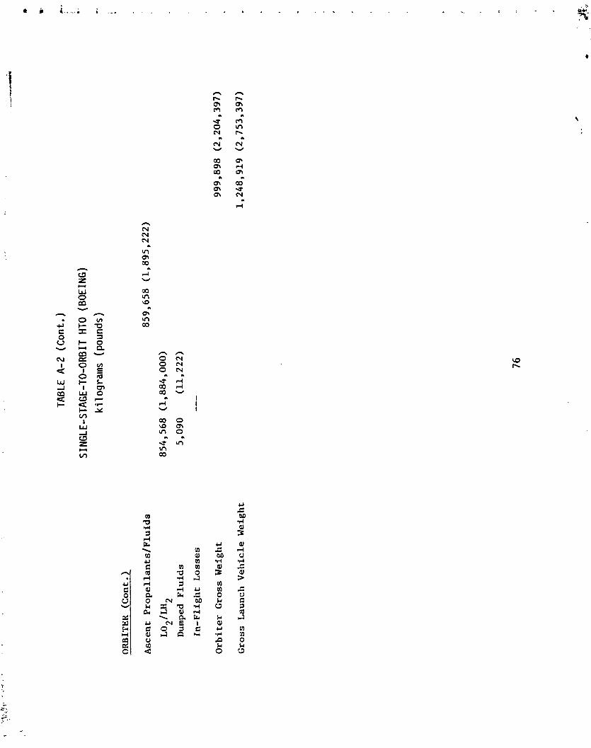
ORBITER (Cont.)
Ascent Propellants/Fluids
LO*/LH~
Dumped Fluids
In-Flight Losses
Orbiter Gross Weight
Gross Launch Vehicle Weight
TABL
E A
-2
(Co
nt.
)
S IN
GLE-
STAG
E-TO
-ORB
IT HTO
( BOE
ING)
k
i 1 og
ram
s (p
ound
s)

BOO
STER
: xu
ctu
re
Bo
dy
/~a
ce
lle
Gro
up
Win
g G
roup
Ta
il G
roup
Th
erm
al P
ro
tec
tio
n S
yste
m
Lan
din
g ;m
ar
En
gin
e S
ec
tio
n
Co
nti
ng
ency
Pro
pu
lsio
n
Tu
rbin
e E
ng
ines
Roc
ket
E
ng
ines
Air
In
-Su
ctio
n
and
E
xhau
st
Fu
el-/
P:-
up
ella
nt
Sys
tem
Oth
er
Co
nti
ng
ency
Eq
ui~
rnen
t
Fli
gh
t C
on
tro
ls
Ele
ctr
ica
l S
yste
m
Hy
dra
uli
c S
yste
m
Pow
er
Av
ion
ics
Bo
ost
er E
mpt
y W
eigh
t
TABL
E A
-3
TWO-
STA
GE-T
O-OR
B IT
(ALL
ROC
KET
POW
ERED
)
Ki 1
ogra
ms
( pou
nds )

BOOSTLR (Cont . )
Staging Load
Residuals
Reserves and Landing
Flyback Fuel
Booster Weight At Staging
Boost Propellants
JP
LO
,/L
H~
Rooster Gross Weight
OK
BIT
ER
Structure
Body Group
Wing Group
Tail Group
Thermal Protection System
Landing Gear
Contingency
TABL
E A
-3
(Co
nt.
)
TUO-
STA
GE-
TO-O
RE I
T (
ALL
RO
CKET
POW
ERED
)
Ki 1
ogra
ms
(pou
nds)

ORBITER (Cont . ,
Propulsion
Rocket Engines
Propellant System
RCS and OMS
Contingency
Equipment
Crew/Payload Provisions
Flight Controls
Electrical Power
Hydraulic System
Environmental Control System
Avionics
Contingency
TABL
E A
-3
(Co
~t.
)
TWO
-STA
GE-
TO-O
RB
IT
(ALL
RO
CKET
PO
WER
ED)
Ki 1
ogra
ms
(pou
nds)
Orbiter Empty Weight
I.:jected
Load
Crew
Residuals
RCS Propellant
OMS Propellant
Reserves
Retained Fluids
Payload

OR
BIT
ER
(C
on
t.)
Orb
iter
In
jec
ted
Wei
ght
Asc
ent
Pro
pel
lan
t/F
luid
s
LO
~/
L~
~
Dum
ped
Fluids:
In-F
lig
ht
Lo
sses
Orb
iter
Gro
ss W
eigh
t
Sys
tem
Gro
ss W
eigh
t
TABL
E A
-3
(Co
nt.
)
TWO-
STAG
E-TO
-ORB
IT
(A
LL R
OCKE
T PO
WER
ED)
Ki l
ogra
ms
(pou
nds)

TABL
E A-
4
TWO
-STA
GE-
TO-O
RB
IT
(S
UB
SON
I C
STA
GIN
G,
SIN
GL
E
BO
OST
ER,
COM
PACT
CA
RGO
BAY
)
Ki l
ogra
ms
(pou
nds)
BO
OST
ER
WEI
GH
T E
STIM
AT
E
Str
uc
ture
Win
g G
rou
p
65
,99
8
Ta
il G
rw
p
9,0
72
Bod
y G
rou
p
(in
clu
de
s n
ac
ell
es
) 2
7,2
15
Lan
din
g G
ear
42
,45
6
Lau
nch
S
tru
ctu
re
4,5
36
kro
pu
lsio
n
* T
urb
ofa
ns
(12
JT-9
D-7
0B)
49
,83
2
Fu
el
Sy
stem
2
,26
8
Oth
er
51
7
Eq
uip
men
t
Fli
gh
t C
on
tro
ls
2,7
21
Ele
ctr
ica
l 1
,54
2
Hy
dra
uli
c
2,2
68
Au
xil
iary
Po
wer
S
yst
em
54
4
Av
ion
ics
1,1
34
Cre
w P
rov
isio
ns
---
- --
* Use
of
16
F-1
00-P
b-
"
: *re
s in
pla
ce
of
12
3T
-9D
-70B
er
igin
es w
ou
ld
ha
ve
th
e f
oll
ow
ing
estimate
imp
act
on
we
igh
t st
:crb
a-
L;
(1)
cn
gin
e w
eig
ht
wo
uld
d
ec
rea
se t
o a
bo
ut
21
,77
2
kg
(4
8,0
00
lb)
from
4
9,8
32
k
g (109,8<,0 ib
);
(2)
the
na
ce
lle
we
igh
t w
ou
ld
de
cre
ase
by
a
bo
ut
6,8
04
k
g
(15,0
00
lb);
(3
) g
ross
we
igh
t w
otl
d
rem
ain
ab
ou
t th
e s
am
e s
inc
e f
ue
l fl
ow
s w
ou
ld
inc
rea
se
ab
ou
t 2
.5 times.

TABL
E A
-4
(Con
t. )
TW
O-S
TA
GE
-TO
-OR
BIT
(S
UB
SON
IC
STA
GIN
G,
SIN
GL
E
RO
OST
ER,
COM
PACT
CAR
GO B
AY)
Ki 1
ogra
ms
(po
un
ds)
BOOSTER W
EIG
HT
EST
IMA
TE
(C
on
t.)
Br,
ost
er Em~*y W
eig
ht
Cre
w
Re
sid
ua
ls
Re
serv
es,
S
ho
rt F
lyb
ack
, an
d
Lan
din
g
Off
se
t F
uel
Bo
ost
er
Wei
gh
t a
t S
tsg
ing
Bo
ost
er
Pro
pe
lla
nts
(M
ach
0.3
8/S
L
to
Mac
h 0
.81
22
k
ft)
JP
(<
5
0(,
0 I
b}
LOX
(i
n o
rbit
er
tan
ks)
LH2
(in
orb
ite
r ta
nk
s)
Eo
os t
sr
Gro
ss W
eig
ht
(c-e
ludin
g
bo
ost
er
pro
pe
lla
nts
in
orb
ite
r)
So
ost
er
Pro
pe
lla
nts
in
Orb
ite
r 1
02
,51
2
(22
6,0
00
)
LO
X
88
,84
4
(1-9
5,8
67
)
LH
13
,66
8
(30
,13
3)
Orb
ite
r C
ross
Wei
gh
t a
t S
tag
ing
Sy
stem
Cro
ss W
eig
ht
at
Lif
t-o
ff
Ta
xi
Pro
pe
lla
nts
(J
P)

TABL
E A
-4
(Co
nt.
)
W3-
STA
GE-T
O-OR
B I i (
SUB
SONI
C ST
AGIN
G,
SIN
GLE
BOO
STER
, CO
MPA
CT C
ARGO
BAY
) K
i 1 og
ranl
s (p
ound
s )
BOO
STER
W
EIG
HT
EST
IMA
TE
(C
on
t.)
Rm
way
Pro
pe
Lla
nts
J?
LOX
(in
or
blt
er
)
I.H2
(In
or
bit
er
)
Ram
p G
ross
Wei
ght
OR
BIT
ER
W
EIG
HT
ES1;MATE
Str
uc
tur
e
Win
g C
rou
p
Ta
il C
rou
p
Bod
y C
rou
p
Th
erm
al
Pr
ote
cti
on
Sy
stem
(e
xte
rn
al)
Str
uc
tur
e C
on
tin
gen
cy
(10
%)
Pro
pu
lsio
n
Ro
cket
E
~i~
inc
s
(th
r5
e
596,
000
1~ gA
c!
RCS
and
O
MS
Pro
pu
lsio
n
con^
ing
;?n
cy (
5%
)

TABL
E A
-4
(Con
t. )
TWO-
STAG
E-TO
-ORB
IT (
SUB
SONI
c ST
AGIN
G, SIN
GLE BO
OSTE
R, COM
PACT
CAR
' RA
Y )
ORBITER WEIGHT ESTIMATE (Cont.)
Equipment
CrewIPayload Provisions
Flight Controls
Electrical
Hydraulic
Environmettal Control System
Avionics
Equipment Contingency (5%)
Orbiter Empty Weight
' ,l jec ted Load
Crew
Residuals
RCS Propellants (100 ftlsec)
OMS Propellants (650 ftlsec)
Reserves
Subsystem Retained Fluids
Payload
Injected Weight
Ki 1
ogra
ms
(pou
nds)

h n n 0 0 0 0 0 0 o o m

a a a 1 1 s 0 0 0 k k k 2 0 u cl

TABLE
A-5
(Cont. )
(SUBSONIC STAGING, SINGLE BOOSTER, PARAMETRICALLY RESIZEO FOR SHUTTLE CARGO BAY)
Ki lograms (pounds)
BOOSTER WEIGHT ESTIMATE (Cont.)
Booster Empty Weight
Crew
Residua1.s
Reserves, Short Flyback and
Landing
22,679
(50,000)
Offset Fuel
(1FR)
Booster Weight at Staging
Boost Propellants (Mach 0.38/5.1
to Mach 0.8/22 kft)
LOX (in orbiter tanks)
LH2 (in orbiter tanks)
Booster Gross Weight (excludes
boost propellants in orbiter)
Boost Propellants in Orbiter
112,717
(248,500)
LOX
97,681
(215,350)
LH2
15,036
(33,150)
Orbiter Gross Weight at Staging
937,575 (2,067,000)
System Gross Weight at Lift-off
Taxi Propellants (
JP
)

TAB
LE A
-5 (Cont .
) (S
UB
SON
IC
STA
GIN
G,
SIN
GLE
BO
OST
ER,
PARA
MET
RICA
LLY
RE
SIZ
ED
FOR
SH
UTT
LE C
ARGO
BAY
) K
i log
ram
s (p
ound
s)
BOOSTER WEIGHT ESTIMATE (Cont.)
Runway Propellants
JP
LOX (in orbiter)
LH2
(in orbiter)
Ramp Gross Weight
ORBITER W
EIGHT ESTIMATE
Structure
Wing Group
Tail Group
Body Group
Thermal Protection System
(external)
Landing Gear
Structure C
ontingency (10%)
Propulsion
Rocket Engines (three
59
6,0
00
lbVAC)
RCS and OMS
Propellant System/Misc.
Propulsion Contingency (10%)

TABL
E A
-5
(Co
nt.
)
(SU
BSO
NIC
ST
AG
ING
, SI
NG
LE B
OO
STER
, PA
RAM
ETRI
CALL
Y R
ESIZ
ED F
OR S
HUTT
LE C
ARGO
BA
Y)
Ki 1
ogra
ms
(pou
nds
)
ORBITER WEICHT ESTIMATE (Cont.)
Equipment
~rewfPay1oad Provisions
Flight Co~~trols
Electrical
Hydraulic
Environmental Control System
Avionics
Equipment Contingency (5%)
Orbiter Empty Weight
Injected Load
Crew
Residuals
RCS Propellants (100 ft/sec)
OMS Propellants (650 ft/sec)
Reserves
Subsystem Retained Fluids
Payload
Injected Weight

TABL
E A
-5
(Con
t.)
(SUB
SONI
C ST
AG1 R
G,
SIN
GLE
BOO
STER
, PA
RAM
ETRI
CALL
Y R
ESIZ
ED F
OR S
HUTT
LE C
ARGO
BAY
) Ki 1
ogra
ms
(pou
nds)
ORBITER WEIGHT ESTIMATE (Cont.)
Post-Staging Ascent Propellants
LOX
2
Dumped Fluids
In-Flight Losses
Orbiter Gross Weight at Staging
Boost Propellants in Orbiter
LOX
Li1
2
Orbiter Lift-off Weight
Runway Propellants (in orbiter)
LOX
LH2
Orbiter Ramp Weight

TABL
E A
-6
TWO-
STAG
E-TO
-ORB
IT
(SUP
ERSO
NIC
STAG
ING,
TW
IN
BOOS
TER)
ki
logr
ams
(pou
nds)
BOOSTER (both boosters)
Structure
~ody/Nacelle Group
Wing Group
Tail Group
Thermal Protection System
Landing Gear
Engine Section
Contingency
Propulsion
Turbine Engines
Scranjet Engines
Air Inductjon and Exhaust
Fuel/Propellant System
Contingency
Equipment
Fliqht Controls
Electrical System
Hydraulic System
Power
Avionics
Booster Empty Weight

TABLE A-6 (Cont.)
TWO-STAGE-TO-ORB IT (SUPERSONIC STAGING, TWIN BOOSTER)
ki 1
ograms (pounds)
BOOSTER (Cont.)
Staging Loading
Residuals
Reserves and Landing
Flyback Fuel
Booster Weight at Staging
Boost Propellants
JP
L02/LI12
Booster Gross Weight (both
boosters)
ORBITER
Structure
80,308
(177,050)
Body Group
29,483
(65,000)
Wing Group
18,144
(40,000)
Tail Group
2,268
(5,000)
Thermal Protection System
17,009
(37,500)
Landing Gear
6,123
(13,500)
Contingency
7,280
(16,050)

TABL
E A
-6
(Con
t . )
TWO
-STA
GE-
TO-O
RB
IT (
SUPE
RON I C
STA
G1 N
G,
TWIN
BO
OST
ER)
ki ! og
ram
s (p
ound
s)
ORBITER (Cont . )
Propulsion
Rocket Engines
Propellant System
RCS and OMS
Contingency
Equipment
Crew/Payload Provisions
Flight Controls
Electrical Power
Hydraulic System
Environmental Control System
Avionics
Contingency
Orbiter Empty Weight
Injected Load
Crew
Residuals
RCS Propellant
OMS Propellant
Reserves
Retained Fluids
Payload

TABL
E A
-6
(Con
t. )
TWO
-STA
GE-
TO-O
RB
IT (
SUPE
RSO
NIC
ST
AG
ING
, TW
IN B
OO
STER
)
ki 1
ogra
ms
(pou
nds
)
ORBITER (Cont . )
Orbiter Injected Weight
Ascent Propellants/Fluids
LO~/LH~
Dumped Fluids
In-Flight Losses
Orbiter Gross Weight
System Gross Weight

BOOSTER
Structure
Bdy/Nacelle Croup
Wing Croup
Tall Group
Thermal Protection System
Landing Cear
Engine Section
Contingency
Propulsion
Turbine Engines
Scr
am
jet Engines
Air Induction and Exhaust
Fuel/Propellant System
Con t l uyency
Equipment
Flight Controls
Electrical System
Hydraulic System
Power
Avionics
TABL
E A-
7
TWO-
STAG
E-TO
-ORB
IT
(HY
PERS
ON I C
STAG
ING
)
k i 1 o
gram
s (p
ound
s )
Booster Empty Weight

TABL
E A-
7 (Cont .)
BOO
STER
(C
ont . )
Sta
gin
g L
oad
Re
sid
ua
ls
Reserves
and
L
and
ing
Fly
ba
ck F
ae
l
Bo
ost
er Weight
at
Sca
gin
g
Boo
st
Pr
op
ell
an
ts
JP
LH
2
Ba
ost
er
Cro
ss W
eigh
t
ORBITER
--
Str
uc
tur
e
Bo4
y C
rou
p
Win
g G
rou
p
;'a
il
Gro
up
Th
erm
al
Pr
ote
cti
on
Sy
stem
Lan
din
g C
ear
Co
nti
ng
ency
TWO
-STA
GE-
TO-O
RBIT
(H
YPER
SONI
C ST
AGIN
G)
kilo
gram
s (p
ound
s)

TABL
E A-
7 (C
on
t.)
TWO
-STA
GE-
TO-O
RB
IT (
HYP
ERSO
NIC
STA
GIN
G)
ki 1
ogra
ms
(pou
nds)
OR
BIT
ER
(C
on
t.)
Pro
pu
lsio
n
Rock
et
En
gin
es
Ro
pel
lan
t S
yst
em
RCS
and
O
MS
Co
nti
ng
ency
Eq
uip
men
t
Cre
w/P
aylo
ad
P
ro
vis
ion
s
Fli
gh
t C
on
tro
ls
Ele
ctr
ica
l P
ower
Hy
dra
uli
c S
yst
em
En
vir
on
men
tal
Co
ntr
ol
Syst
em
Av
ion
ics
Co
nti
ng
ency
Orb
iter E
mpt
y W
eigh
t
Inje
cte
d L
oad
Cre
w
Resi
du
als
RCS
Pr
op
ell
an
t
OM
S P
ro
pe
lla
nt
Res
erv
es
Ret
ain
ed
Flu
ids
Pa
ylo
ad


Chamber Pressure (psi)
Expansion Ratio
0
10,000
20,000
30,000
40, OCO
SO, 000
60,000
70,000
80,000
90,000
100,000
150,000
~2OO,OOO
TABL
E A
-8
UPRA
TED
SSM
E C
HA
RA
CTE
RIS
TIC
S
3450
821150
Thrust
Newtons (lb)
2,015,489
(453,100)
2,231,672
(501, 700)
2,349,995
(528,300)
2,439,405
(548,400)
2,498,565
(561,700)
2,535,04112,532,372 (569,900/569,300)
2,579,041
(580,000)
2,607,992
(586,300)
2,623,561
(589,800)
2,633,34'
(592,000)
2,639,574
(593,400)
2,641,798
(593,900)
2,651,139
(596,000)
Specific Impulse, ~
-~
/k
~

TABL
E A
-9
Rocket Booster :
Subsonically Launched Orbiter:
* Private communication from 5
. Watt, Aerodynamic Coefficient Data and Scramjet Performance
Data Package, July 1977.
100

TABL
E A
-10
* Source:
see
foo
tno
te t
o Table
A-9
'~ncludes viscous drag
101

TABL
E A-
1 1
2
Turbojet Engines (A
= 2.2
m /engine)
C
2 Scramjet (A
= 157 m
total)
C
Mn -
-
C~
Specific Impulse
(3P
Fuel)
-
Mn
-
C~
Specific Impulse
(LH
2 Fuel) ,N-s/kg
(N-sec/kg)
* Source:
see footnote to Table A
-9


TABL
E B-
1
SING
LE-S
TAG
E-TO
-ORB
IT
(Ma
rtin
VTO
) I
Tec
hrl
olo
gy
i
Tec
hn
olo
gy
R
ea
din
ess
R
ea
din
ess
L
ev
el
Re
qu
ire
d
Le
ve
l R
eq
uir
ed
Gain -
Risk
Tec
hn
olo
gy
Nee
d
Lau
nch
V
eh
icle
Str
uc
ture
- A
ero
dy
nam
ic
Su
rf a
ce
s
Win
gs
(dry
win
gs)
. Hori
zo
nta
l an
d V
ert
ica
l S
tab
iliz
ers
. Con
tro
l S
urf
ac
es,
F
ins,
and
F
air
ing
s
- B
ody
an
d T
ank
s
Inte
gra
l P
rop
ell
an
t T
ank
s (i
ns
ula
tio
n,
he
at
sin
k,
se
ali
ng
)
Lo
ad
Ca
rry
ing
Str
uc
ture
(t
hru
st,
in
tert
an
k,
win
g
bo
dy
, in
ters
tag
e)
. Pro
pe
lla
nt
Feed
, F
ill,
D
rain
, an
d
Tra
nsfe
r (p
res
su
riz
ati
on
, a
nti
-slo
sh
)
- L
an
din
g
Gea
r
Str
uts
, B
rac
es,
a
nd
Dep
loy
men
t D
ev
ice
s
Sh
ock
Att
en
ua
tio
n D
ev
ice
s
. Tire
s

TABL
E B
-1
(Con
t. )
SING
LE-S
TAG
E-TO
-ORB
IT
(Mar
tin
VTO
)
Tec
hn
olo
gy
T
ech
no
log
y
Re
ad
ine
ss
Re
ad
ine
ss
Le
ve
l R
eq
uir
ed
L
eve 1
Re
qu
ire
d
Gai
n -
Ris
k
Tec
hn
olo
gy
Nee
d -
Lau
nch
V
eh
icle
(C
on
t . )
e T
her
mal
P
rote
cti
on
Sy
stem
(TPS)
- C
ov
er P
an
els
(R
SI,
h
ot
str
uc
ture
s,
bo
nd
ing
ma
teri
als
, lo
ca
l a
bla
tors
, s
tru
ctu
ra
l in
terf
ac
e)
- In
su
lati
on
- M
eta
l H
eak
S
ink
- T
ran
spa
ren
t A
rea
s
Gu
idan
ce a
nd
N
av
iga
tio
n
- G
uid
an
ce R
efe
ren
ce
- G
uid
an
ce E
va
lua
tio
n a
nd
C
on
tro
l O
utp
ut
Co
mm
un
icat
ion
s
- A
nte
nn
a S
yst
em
s
- T
ran
sm
itte
r E
qu
ipm
ent
- T
ran
sce
ive
r E
qu
ipm
ent
- T
ele
vis
ion
S
yst
em
Inst
rom
en
ta t
ion
Pa
ne
ls
- S
en
sors
- S
ign
al
Pro
ce
ssin
g,
Tra
nsm
issi
on
, a
nd
Dis
pla
y
- C
rew
S
tati
on
an
d
Fli
gh
t C
on
tro
ls

TABL
E B
-1
(Co
nt.
)
SIN
GLE
-STA
GE-
TO-O
RB
IT
(Ma
rtin
VTO
)
Tec
hn
olo
gy
T
eclm
olo
gy
R
ea
din
ess
R
ea
din
ess
L
ev
el
Re
qu
ire
d
Le
ve
l R
eq
uir
ed
G
ain
T
ech
no
log
y N
eed
Lau
nch
V
eh
icle
(C
on
t . )
Po
wer
S
up
ply
an
d
Dis
trib
uti
on
- E
lec
tric
al
. Pow
er
Ge
ne
rati
on
(e
ng
ine
g
en
era
tor
un
it,
fu
el
ce
lls,
ba
tte
rie
s, RTG,
ga
s g
en
era
tor)
Po
wer
C
on
ve
rsio
n a
nd
D
istr
ibu
tio
n
- H
yd
rau
lic
s
. Pow
er
Co
nv
ers
ion
an
d D
istr
ibu
tio
n
(hy
dra
uli
c,
pn
eu
ma
tic
)
En
vir
on
me
nta
l C
on
tro
l an
d L
ife
Su
pp
ort
- P
ers
on
ne
l A
cc
om
od
ati
on
s an
d
Eq
uip
men
t
- L
ife
Su
pp
ort
Eq
uip
men
t
- E
nv
iro
nm
en
tal
Sy
ste
ms
(te
mp
era
ture
an
d a
tmo
sph
eri
c c
on
tro
l)
Aer
od
yn
amic
s
- C
on
fig
ura
tio
n
Liq
uid
R
ock
et
En
gin
e (
s)
- SS
HE
(p
ote
nti
al
mo
dif
ica
tio
ns,
n
oz
zle
, li
feti
me
, p
erf
orm
an
ce
)
- New
Hig
h
Pre
ss
ure
LH
-LO
2
2 -
New
Hig
h
Pre
ss
ure
HD
-LO
2 (p
oss
ibly
d
ua
l-fu
el)
- O
W (
ex
isti
ng
MMH/N2O4,
mo
dif
ica
tio
ns
o
r LH
,-LO
,

TABL
E B-
1 (C
ont.
)
SI N
GLE
-STA
GE-
TO-O
RBIT
(Mar
tin
YTO
)
Tec
hn
olo
gy
T
ech
no
log
y
Rea
din
ess
Re
ad
ine
ss
Le
ve
l R
equ
ired
L
ev
el
Req
uir
ed
Gai
n -
Rf s
k
Tec
hn
olo
gy
N
eed
Lau
nch
Ve
hic
le
(Co
nt . )
Att
itu
de
Co
ntr
ol
En
gin
es
- E
xis
tin
g T
hru
ste
rs
(MM
H/N
0 )
2 4
- N
ew
Th
rust
ers
(N
H
/N
0
or
LH
-LO
)
24 24
2 2
Air
-Bre
ath
ing
E
ng
ines
- S
ub
son
ic T
urb
ofa
n J
et
En
gin
e (e
xis
tin
g e
ng
ine
) -
- N
ew S
ub
son
ic T
urb
ofa
n J
et
En
gin
e (7
0-8
0,0
00
lb
f)
- -
Ex
isti
ng
Su
pe
rso
nic
Tu
rbo
jet
or
Tu
rbo
fan
(5
-58
, C
E-4
) -
- N
ew S
up
ers
on
ic T
urb
oje
t (7
0-8
5,0
00
Ib
f)
- -
Sc
ram
jet
(su
pe
rso
nic
b
urn
ing
) -
- C
ombi
ned
Ram
jet-
Scr
amje
t (s
ub
ca
sic
plu
s s
up
ers
on
ic b
urn
ing
) -
Ma
nu
fac
turi
ng
Ma
nu
fac
turi
ng
Pro
ce
ss a
nd
Met
ho
ds
To
oli
ng
- P
lan
nin
g,
De;
ign,
F
ab
ric
ati
on
, A
ssem
bly
of
To
ols
, D
ies,
J
igs
, an
d
Fix
ture
s
- T
est
E
qu
ipm
ent
to S
up
po
rt M
an
ufa
ctu
rin
g
- P
rog
ram
ing
an
d P
rep
ara
tio
n o
f T
apes
an
d M
ach
ines
fo
r N
um
eri
ca
lly
Co
ntr
oll
ed
Eq
uip
men
t

TABL
E 0-
1 (C
on
t. )
SING
LE-S
TAG
E-TO
-ORB
IT
(Ma
rtin
VTO
)
Tec
hn
olog
y 1
Technology
Readiness
Ree
d iness
Level
Required
@' i !
Leve 1
Required
Ca in
Risk
-
-
Teclmology Need
Ground Equipment
Planning, Design, Fabrication, and Testing
Instrumentation and Test Equipment (automated checkout
and maintenance)
Test llardware
Ground Test (sixuctural, dynamic, propulsion and system
integration, wind tunnel)
Flight Test (instrumentation, test articles, and special
equipment)
Facilities and Equipment
Vehicle Test Facilities
Engine Test Facilities
r Launch Faciltties
Operational and Maintenance Facilities
0 .%nufacturiug
Facilities
Wind Tunnel Facilities
0 Propellant Production Facilities

Slmulators and Special Timing Equipment
Flight
m Operations
Maintenance
TABL
E B-
1 (C
on
t.)
SING
LE-S
TAG
E-TO
-ORB
IT
(Ma
rtin
VTO
)
Technology
Teclrnology
Readiness
Rerdinese
Level
Required
level
-
.--
Required
Gain
Risk -
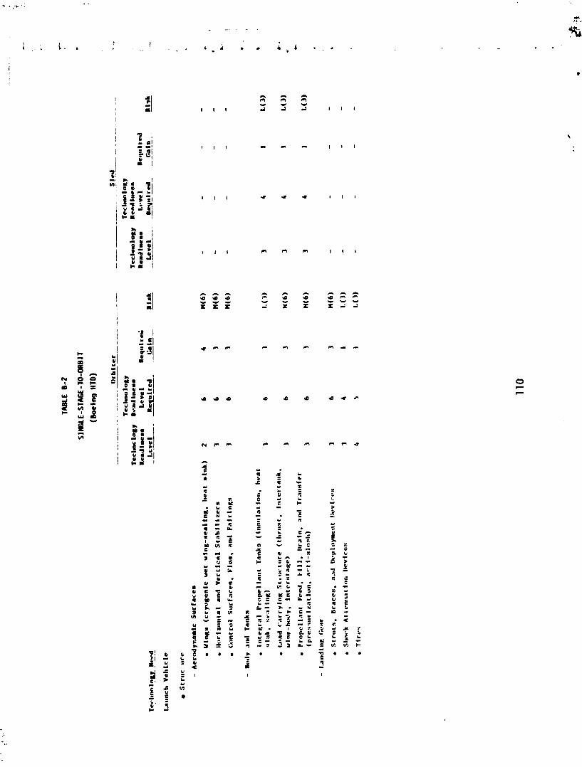
LI I CI - A A - C . A
Z S t P 9 9 a n - w - w - - -
x x x -1 x x x i - 1

lAR
LE 8
-2
(Co
nt.
)
SIN
GLE
-STA
GE-
TO-O
RB
IT
(Boe
ing
HTO
)
---
or
bll
er
._
sLen.
Te
cl~
no
log
y
Te
cl~
no
log
y
Te
clm
olo
gy
R
ea
din
en
s T
ec
hn
olo
gy
R
ea
dit
ten
s
Rea
din
ems
Le
ve
l R
eq
ulr
ed
R
ead
8 n
es
s
Le
ve
l R
eq
ulr
d
Ga
in
Req
uir
ecl
Rla
k
Lev
el
Rls
k
--
- &
In
Le
ve
l R
equi
red_
- 'l
ec
l~
nv
lu
~
Need
1.a
un
ch
Ve
hic
le
(Co
nt.
)
r
Th
erm
al
Pro
tec
tlc
m
Sy
ste
l (T
PS
)
- C
ov
er
Pa
ne
ls (RSJ, h
ot
str
uc
ture
s.
bo
nd
ing
m
ate
ria
ls,
loc
al
ab
lato
rs)
- l
~~
s:
~l
at
Io
n
- m
eta
l ll
ead
S
ink
- T
ran
sp
are
nt
Are
as
Cu
ida
nc
e a
nd
Na
vtg
a- t
on
- C
uld
an
ce
R
ef e
re~
hc
e
- C
uld
a~
lce
Ev
alu
ati
o~
~
an
d
Cv
ntr
ol
01
1tp
ut
- C
rew
Sta
t to
n
imd
F
l Ig
ht
Co
nL
rols

TABL
E 8-
2 (C
on
t. )
SIN
GLE
-STA
GE-
TO-O
RB
IT
(Boe
i ng
I1TO
)
Tec
lrn
olo
gy
T
eclm
nolo
gy
Tec
l,n
olo
&y
R
ea
din
ess
T
ech
no
log
y
Ren
dln
ess
Req
uir
ed
Ren
d ln
es
s
Lev
el
Req
uir
ed
Re
ad
ine
ss
I.e
vd
Ca i
n
Req
uir
ed
Rink
C
hin
R
isk
L
eve 1
-
Le
ve
l R
equ
ired
- --
Tec
hn
olo
gy
Nee
d
Lau
nch
Ve
hic
le
(Co
nt.
)
r P
ower
S
up
ply
an
d
Dis
trib
uti
on
- E
lec
tric
al
Pow
er
Ge
ne
rati
on
(e
ng
ine
ge
ne
rato
r u
nit
. fu
el
ce
lls
, b
att
eri
es
. R
IT,
ga
s
ge
ne
rato
r)
4
Pow
er
Co
nv
ers
ion
an
d
Die
trih
uti
on
5
- Il
yd
rau
llc
s
. Pow
er
Co
nv
ers
ion
an
d D
istr
ibu
tio
n
(I~
yd
rau
lic
, pn
eu
an
~ic
)
r E
nvir
onm
enta
l C
on
tro
l a
nd
Lif
e S
up
po
rt
- P
ers
on
ne
l A
cc
om
da
t io
ns
an
d
Equ
lp
rnen
t
- L
ife
Sq
pp
ort
Eq
ulp
nen
t

TABL
E 8-
2 (C
on
t.)
SING
LE-S
TAG
E-TO
-ORB
IT
(Boe
lng
HTO
)
---
Orb
ite
r ------.--
Sle
d
Te
cl~
~to
log
y
Te
ct~
lwlu
gy
T
eclm
ulo
py
R
ca2
lne
sa
Te
cl~
no
lu~
y Rea
d hem
s R
ead
lnea
s L
evel
R
eq
ult
ed
R
en
dlr
~e
as
Lev
el
Req
uir
ed
Lev
el
Ga
in
Le
ve
l -
.
- K
lsk
R
equ
ired
---
---
Ris
k
-
Ce
In
La
u~
~c
h
Ve
hic
le
(Co
nt.
)
. .
Liq
uid
Ro
cket
E
np
,in
e(s)
- S
SU
E
(po
ten
tia
l lu
d:f
ica
tto
ns
, n
oz
zle
, 11 F
etir
ne,
p
erfu
rman
cr.)
- N
au
l
li
~h
Pre
ss
ure
L1I
2-M
2 -
- N
ew H
igh
P
ress
ure
IID
-I.C
i 2
- -
OM
S (e
xjs
tin
g N
NII
IN~
U~
, w
di
f ic
at I
on
s N
2~
4/N
20
4,
or
1.11
-1.0
) 3
2 2
. Att J
ttd
r C
on
tro
l E
lr~
ine
s
- E
xts
ttn
g T
l~rc
~rc
ters
()
.Otl
l/N
0 )
2 4
-
New
T
hru
ste
rs
(N2
ll4
/N2
O4
, o
r L
IIZ-1
.0
) 4
- S
~rb
sorr
f c T
urb
ofa
n .
kt E
llg
lae
(ex
isti
ng
en
gin
e)
- -
Ncw
S
ub
son
ic T
urh
c~C
an Je
t R
ng
ire
(70-8
0,O
W
Ibl)
-
- E
xln
tln
p,
Su
pe
rso
nic
Tu
rbo
jet
or
Tu
rl~
ofn
n
(J-S8,
CE
-4)
- N
cu
Sc~
per
::r~
r~ic
l'
url
~o
jei (7
0-8
5,M
)O
Ihf)

TABL
E 0
-2 (
Co
nt.
)
SING
LE-S
TAG
E-TO
-ORB
IT
(Boe
ing
HTO
)
Orb
ite
r
Tec
hn
olo
gy
T
ech
no
log
y
Re
ad
ine
ss
Rea
dln
esa
Le
ve
l --
Le
ve
l R
equ
ired
Te
cl~
no
log
y
Tec
tmo
log
y
Re
ad
ine
ss
Re
ad
lne
ss
Lev
el
Le
ve
l R
equ
lred
--- -
Req
ulr
ed
Gai
n
Rls
k
-
Te
fl~
~io
log
y
Nee
d
Uen
uf a
c tu
rin
g
0
kta
nu
fac
turi
ng
Pro
ce
ss a
nd
H
eth
od
s
To
uli
ng
- F
lan
hln
~, D
esig
n,
Fa
bri
ca
tio
n.
Ass
emb
ly
of
To
ols
, D
lea.
J
igs
, an
d
Fix
l*~
res
- T
est
E
qu
ipm
ent
to S
op
po
r t
Uan
uf a
ctu
r in
g
- P
rog
ram
ing
an
d
Pre
pa
rati
on
o
f T
apes
anc
l H
ac
hi~
~e
s
for
N~
~w
rl
ca
ll
y
Co
ntr
oll
ec
l E
qu
ipm
ent
Cro
c~n
d E
qu
ipm
ent
0
P~
RI
II
I~
II
~.
Dcs
ign
. F
ab
ric
ati
on
, an
d T
es
t ln
g
Ins
tr~
me
nta
tlo
n an
d T
est
E
qu
ipm
ent
(au
tom
ated
cl
ierk
ou
t a
nd
ma
lnte
na
nc
e)
Te
st
llar
clw
are
. (:roun
d T
est
(s
trt~
ctu
ral.
dy
nam
ic,
pro
pt~
lu
ion
ori
d s
ys
t (.m
In
lep
,rn
tio
n,
uln
d
t~
~n
ne
l)
. I:llg
ht
Te
st (
inet
rurn
eaL
atio
n.
Le
st
art
icle
s.
and
s
pw
ial
equip
men
t)

T~c&
"_~;
l~~y
-Nt$
~l
Fi~
cil
ltir
s an
d
Eq
~~
lpn
en
t
0
Ve
hic
le T
est
Fa
cll
itle
s
0
En
~tn
e Te
st F
ac
llit
les
0
1.i1
unch
Fa
cil
itie
s
Op
era
tio
na
l an
d h
inte
na
nc
e F
ac
llft
ies
r
Ma
nu
fact
uri
ng
Facil
itie
s
r W
ind
Tu
nn
el
Fa
ct I
f t
ies
0
Pr
op
ell
en
t P
rod
trct
too
Fa
cll
ltle
s
TABL
E 8-
2 (C
on
t.)
SINGLE-STAGE-TO-ORBIT
(Boe
ing
HTO
)
-
-
Orb
iter
Tec
ltn
olog
y R
ead
inee
s L
evel
--
Tec
ltn
o lo
gy
Xea
d i~
tee
s
I.ev
el
Req
ulr
ed
Cn
111
Req
ulr
ed _
Tec
l~n
u
Ln
~y
T
ech
nol
ogy
Rea
dln
eee
Rea
dln
eee
Lev
el
Lev
el
Req
ulr
ed _

TABL
E 8-
3
TWO-
STAG
E-VE
HICL
E (R
ock
et R
oo
ster
) t".
> .;
f '
:
i T
tch
no
lo~
y
Tec
l~e
u
log
y
Tec
lln
olo
gy
R
ea
din
ess
T
ec
l~n
olo
gy
Ue
ad
ir~
ese
R
ead
ines
s L
ev
el
Req
uir
ed
Rea
dln
ens
Lev
el
Re
qu
irn
l L
ev
el
Req
uir
ed
Gai
n
kls
k
kEl!!lcL
d R
isk
-
Le
ve
l -
Ga
in
Te
cl~
no
lo~
y
Nee
d
Lau
nch
V
eh
icle
- A
ero
dy
nam
lc
Su
rfa
ce
s
Wln
gs
(cry
og
en
ic v
et
vln
g-s
ea
lln
g,
he
at
sln
k)
Ho
riz
on
tal
and
V
ert
lca
l S
tab
iliz
ers
. Con
tro
l S
urf
ac
es.
P
lns,
an
d
Fa
lrin
gs
- B
ody
and
T
ank
s
Inte
gra
l P
rop
ell
an
t T
ank
s (i
ns
ula
tio
n.
he
at
sin
k,
se
ali
ng
)
. Land
C
arr
yin
g S
tru
ctu
re (
thru
st,
in
tert
an
k
uln
g-h
od
y,
inte
rsta
ge
)
. Pro
pe
l la
nt
Fee
d.
FiI
1,
Dra
in,
an
d T
ran
sfe
r (
pr
es
s~
~r
lza
t Io
n,
an
tl-s
los
h)
- I.
md
in
g (
:ra
r
Str
nts
, Il
rac
es,
an
d
Dep
loy
men
t D
ev
ice
s
. Slto
ck A
L tt
?nt~
.it ln
n I
)ev
lce
s
Tlr
es

TABL
E 8-
3 (C
ont.
)
TWO
-STA
GE-
VEHI
CLE
(Ro
cket
B
oo
ster
)
Bo
oste
r O
rblt
er -
Te
clm
olo
~y
T
ec
l~~
~o
lng
y
Te
ch
no
log
y
Rco
d ln
es
a
Te
ch
no
lo~
y R
ea
din
ess
R
eodln
eea
Le
ve
l H
eq
ulr
ed
R
ea
dln
ea
s
Le
ve
l R
equ 1
red
Le
ve
l R
eq
ulr
ed
G
a In
R
lsk
-
Le
ve
l --. R
eq
ulr
ed
--
.- -. O
aln
W
lsk
- --
law
ch
Ve
hlc
le
(Co
nt . )
Th
erm
al
Pra
tec
tio
n S
ys
Le
r (T
PS
O
- C
over
Pa
ne
ls
(RS
[,
ho
t s
tru
ctu
res
, b
on
din
g
na
terl
nls
, lo
ca
l a
hla
tors
)
- In
su
lntl
on
- M
eta
l Il
ea
t S
lnk
- T
ran
sp
are
nt
Are
as
r 1:u
ldnnce
and N
av
lga
t to
n
- (:(
I Lcli~
nce R
eC
cre
nce
- C
uld
itn
c~
Eva
lust io
n a
nd C
on
tro
l O
ut1
111t
. 1:onnlll
llc;I t
Io
ns
- A
ntr
~~
na
S
yntc
ms
- 'T
r;~
nrr
ml t
t rr E
q~
rlp
n~
tin
t
- T
ran
sc
rlv
rr E
:'c
lr~
l~~
mc
nt
- P
elr
vls
lon
Sysio
m
Ins
tr~
~n
en
La
t Io
n P
an
els
- S
en
so
rs
- S
1~
1l.t l
f'r~
ct-
rr~
l I
IR. T
rna
sm
lsslo
n,
and D
lsp
lay
- (:
~-c
w S
tat 10
11 a
1161
F IIR
IIL
Con1 r
ols

TWO
-STA
GE-
VEHI
CLE
(Ro
cket
Bo
ost
er)
Te
ch
no
log
y
Ta
cl~
no
lo&
y
Te
ch
no
log
y
Re
ad
ine
ss
Te
ch
no
log
y
Rea
d l
ne
m
Rea
din
ess
bw
el
Re
qu
ire
d
Rea
din
ess
Le
ve
l R
equ
l re
d
CA I
n
Re
qu
ire
d
Rin
k
Ca
ln
Lev
e 1
-- L
evel
- R
eq
uir
ed
.-
Irk!!!
Tec
lmo
los
y N
eed
Po
ve
r S
up
ply
an
d
nts
trlb
r~
tlo
n
- E
lec
tric
al
Po
wer
G
en
ere
tlo
n
(en
gin
e g
en
er
at
i~
n un
it,
fu
el
ce
lls
, b
att
eri
es
. R
TC
, g
as
ge
ne
rato
r)
5
Po
ve
r C
on
vrr
slo
n an
d
Dis
trih
oti
on
5
- :!
yd
rau
llis
Po
wer
C
on
vP
rs I
on
aed
2b
is:r
lb
uti
on
(h
yd
rau
lic
, p
ne
tma
t: -
.)
En
vlr
otm
ent.
11
C
on
tro
l a
nd
L
ife
SII
III P
- .
- P
ers
on
ne
l A
ccon
mnn
dat l
on
s a
nd
E
qu
ipm
ent
- 1.
1 f
c S
up
per t
Eq
ulp
ne
nt
-
Eu
vl
rc~
rmc
att
nl S
yst
em
s (t
em
pe
ratu
re
an
d
iltm
osl
,llr
r lr
co
ntr
ol)

TABL
E 8
-3 (
Co
nt.
)
(Roc
ket
Boo
ster
)
-
Bo
oste
r
Tecla
nolo
gy
Te
clm
olo
8y
Read ln
es
n
Re
ed
lne
ss
Le
ve
l R
eq
ulr
ed
L
ev
el
Re
pir
ed
C
mln
---
-- -- -
Ris
k
-
Te
clm
olo
~y
T
ec
l~n
olo
gy
Read I ne
ss
Re
ad
itu
se
L
ev
el
Requ l re
d
Re
~p
lr
e~
V
aln
L
ev
el - -
Ris
k
- --
-
r
I.lq
uid
R
ocke
t E
ng
tne
(s)
- S
SN
E
(p
o~
en
tia
l mo
dfi
lca
tlo
ns
. n
oz
zle
. ll
f~
tlm
e. pe
rfo
rmln
ce
)
- Il
rw lll~
l~
P
res
su
re 1
.H -ID
2
2
- N
ew
1{ip
,i1 P
res
su
re I
ll)-L
C)
(po
aa
lbly
d
ua
l-fu
el)
2
-
OM
S
exi
st in
^ W
lI/N
20
4,
ad
iflc
atl
on
s N
I1 /
N 0
or
LII
-1.
0 )
24
2
4'
2 2
Att
Ito
..e
C
on
tro
l E
ng
lne
v
- E
xls
i IIIR
Th
rus
ters
(K
4lI/N
0
2
4
- N
cw
Tl~
rus
ters
(N. I
1 /N
0
or
LII
-1.0
)
24
24
2
2
- N
cw
SII~S
IIII~C
Tu
rlm
f;~
n .l
eL
e
ng
ine
(7
0-8
0,0
00
lbf)
- E
x!ci
t 11
1p; S
up
erw
nlc
T
urb
oje
t o
r T
urb
ofa
n
(.I-
5n
2
rx
-4)
- Nru
Su
pe
rso
nic
T
urb
ole
t (7
0-8
5,0
00
lh
f)

TABL
E 0-
3 (C
ont .
)
TWO-
STAG
E-VE
HICL
E (R
ock
et
Bo
ost
er)
--
hs
t e
r
Te
clm
olo
gy
Te
ch
no
log
y
Rend in
es
s
Re
ad
ine
ss
Le
ve
l R
eqa 1
red
L
ev
el
-
Re
qu
lre
d
Ga
in
Orb
ite
r - . - -
- --
- -
Te
clu
w lo
gy
T
ech
no
loe
y
Rca
dln
ess
Rca
dln
esn
L
ev
el
Re
qu
lre
d
Re
qu
ire
d
Ca
ln
Le
ve
l - -
- -
- - -
r M
an
ufa
ctu
rin
g P
roce
ss a
nd
M
eth
od
s
2 4
2
- P
lan
nin
g.
De
sig
n.
Fa
bri
ca
tio
n.
Asse
mb
ly
of
Tw
ls.
Ute
s.
Ji~
s,
an
d
Fix
ture
s
2 4
2
- T
es
t E
qu
ipm
en
t to
Su
pp
ort
h
nu
fac
turln
g
2 4
2
- Y
ro
~ra
lrln
p: a
d P
rep
ara
tio
n o
f T
apes and
Ha
ch
lne
s fo
r N
um
eri
ca
lly
C
on
tro
lle
d E
qu
ipm
en
t 5
6
PLan~
.*ng.
Ucslg
n.
Fa
brica
tio
n,
an
d T
es
tin
g
3 5
2
r
Ins
tru
me
nta
tio
n a
d T
es
t E
qu
ipm
en
t (a
uto
ma
ted
c
l~rc
ko
rrt a
nd m
ain
ten
an
r-e
)
r C
~OIIII
~ T
est
(rlt
rw
tl~
rn
l. dyn
am
ic,
pr
np
~~
lslm
and
sy
str
n I~
~te
~r
atlo
n.
wln
d tu
nn
el)
r
Fl l
gh
t T
es
t (
Ina
tr~
~m
~~
nL
att
n~
~.
Le
st
nrt
lcle
s.
~III
sp
cc
la l cq
11
1[u
c?
nr)

m Vehicle Test Facllttirs
Ell~lIIe TesL Facllitles
1~11nch
Facll Illre
operational and Malntenance Fa
cili
ties
a Manufacturtn~ Facl Ll t
les
a W11d Tun~~el
Facilities
m, Propellant Product Ion Facllitles
TABL
E 8-
3 (C
on
t.)
TWO
-STA
GE-
VEtII
CLE
(Roc
ket
Bo
ost
er)
hater
--
--
Tectu~ology
Technolo~y Rend ln
es
e
Read1 aeon
Le
ve
1
- La
ve l
Required

TABL
E 0-
4
TWO
-STA
GE
-VE
IIICLE
(A
ir-B
rea
thin
g B
oo
ste
r.
Sub
soni
c S
tag
ing
)
Te
clr
;wlo
~y
T
ec
hw
~lo
~y
T
ech
no lo
gy
Read ln
css
Te
cb
~~
olo
~y
R
ea
Jl~
ten
s
Re
ad
ine
ss
Leve 1
R
eq
uir
ed
R
eadln
em
s L
eve
l R
eq
ulr
erl
R
eq
uir
ed
L
eve
l -
Cn
in
I1.k
--- L
ev
el -
Re
9%
lccd
. G
ain
I1.k
-. --
Te!?!!?
! _uL
!!~?!
lau
nch
Ve
hic
le
Str
uc
ture
- A
ero
dynam
ic
Se
rvic
es
r U
ln
~r
(c
ryo
ee
nlc
w
et
wln
g-s
ea
lin
e.
he
at
sln
k)
5
r tl
ori
zo
ntn
l and V
ertl
crl
Sta
bil
ize
rs
5
, C
on
trrt
l S
urf
ace
s.
Fin
s.
and F
airin
gs
5
- B
od
y a
d T
an
ks
In
te
~ra
l Pro
pe
lla
nt
Tanks
(in
riu
latl
on
. h
ea
t s
ink
, s
ea
lin
n)
- . I~
md
ln
~
Ca
rry
ing
Str
uc
ture
(t
hru
st.
In
tert
an
k.
win
g-b
dy
. in
ters
tag
e)
5
Pro
pe
lla
nt Fred.
Fll
l.
Dra
in, ad T
ran
sfe
r (p
res
su
riz
ati
on
. a
nti
-slo
sh
) 5
- IA
IUI
lng
Ga
r
. Stru
ts.
Bra
cer.,
and D
eplo
ym
ent
I)e
vic
es
5
Sll
urk
fi
t te
ntm
t La
m
(kv
lce
s
5
Tl rrn
3

TYO-
STAG
E -V
EtlIC
LE
( Air
-Bre
ath
ing
B
oo
ster
, S
ubso
nic
Str
gln
g)
Te
ch
olq
y
f rc
lnw
r lomy
Te
ck
nrl
og
y
Re
ad
ine
ss
T
erh
no
lqy
R
ea
dl~
rna
R
ea
dln
ea
r L
ev
el
Re
ys
lr cJ
Ic
ad
lnc
rm
lev
el
Rzq
nL
rr.B
C
aln
k*c 1-
_%!?
_ni_
- -
.-
. R1.k
-- _!*--
.lcw
ecd
_
.- --
G
I l 11
. - -
='*
lau
nc
h Y
eh
lcle
(r
un
t. )
Th
rrw
l P
rote
ctl
o%
Sy
sta
(RS)
- Cu
vrr
P
an
els
(L
SI.
Im
t s
tru
ctu
re.,
b
on
dln
s
wtr
rla
ls.
loc
al
ab
lato
rs)
- le
aru
tat
lon
- &
tia
t lt
rat Slnk
- T
ran
sp
are
nt
Are
as
C~
ld.~
na
rr
ad N
dv
l~a
t
Inn
- C
~s
lda
m:c
Rc
fcre
nre
- (:
r~lr
lan
cc
Ev
nlu
at t
un
ad
mn
tr
al
Ou
tpu
t

TAM
E 8-4
(C
~a
t.)
TW-S
TAG
E-O
RB
IT
(Air
-8re
rth
lng
Bo
aste
r, S
ub
so
nic
S
tag
lng
)
0
Po
wr S
up
ply
an
d D
lstr
lkrtl
on
. Fw
er
Ch
zne
ratl
on
(c
wln
e
#e
ne
rato
r u
nit
, fu
el
ce
lls
. h
alt
erle
s.
RX
. a
s g
en
era
lor)
5
. Po
arr
C
on
ve
rslo
n end
Dla
trlb
utl
on
5
. Pcw
rr
Co
nverm
lon
an
d D
lmtr
?b
ut:
on
(I
~y
dra
ull
c.
pn
etn
~tl
c)
Enulrfmncntel
Cn
ntr
al
an
d L
Ife
Su
pp
ort
- P
crs
n~
na
r 1 A
cc
ah
lat
fan
s a
nd
E
q~
nlp
ea
t
- I.
I Tr
Sas(t
prr
t E
qw
lpcr
eni;
- E
~n
vlr
.~~
~rn
-r~
tnl
Sy
ste
uv
(tm
pe
rr
t~
~r
e
and
.~tr
rvu
pl~
cr
lc I
-on
1 c
ot)

TABL
E 8-
4 (C
on
t. )
TWO
-STA
GE-
VEH
ICLE
(A
ir-B
reat
hin
g
Bo
ost
m.
Sub
soni
c S
tag
lng
)
Llq
uld
R
oc
ke
t E
ng
lne
(s)
- SS
ME
(p
ote
ntl
al
mo
dif
ica
tio
ns
, n
oz
zle
. ll
leti
ne
. p
erf
orm
an
ce
)
- N
ew
lllg
h P
res
su
re L
H LO
2
2
- N
ew
lllg
h
Pre
ss
ure
Il
l)-L
Op
(po
ss
ibly
d
ua
l-fu
el)
- O
MS
(ex
lstt
ng
EM
II/N
Z04
, m
od
lfic
ati
on
s
N I
I /N
0
or
1.11
-L
O2)
2
4
24
' 2
. AtLtt
n~
le C
on
tro
l E
ng
1ac
.s
- C
xl
st
ln
~
Th
rvsL
crs
(M
MIII
N 0 )
2 4
-
New
T
hru
ste
rs
(N
H IN
U
o
r 1
.112
-LO
2)
24
2
4
- S
ul,
son
ic T
nrl
~o
fnn
.le
t E
ng
lne
(
ex
is
~i
ng
en
gin
e)
- N
ew
S~
rhs
on
lc Tu
rho
fan
.Je
t E
ng
ine
(7
0-8
0.0
00
Ib
f)
- E
xls
tln
g S
up
ers
on
ic
Tu
rbo
jet
or
Tu
rbo
fan
(.I-58,
IiE
-4)
- C
mrh
ln
ed
H
:m)e
L-S
vr;
~rn
Je
t (
st~
l~s
on
lc
p 1
11s
~w
pr
rs
on
lr II
~I~
IIII
IK)

TABL
E 8-
4 (C
ont.
)
TWO
-STA
GE-
VEIII
CLE
(A
lr-B
reat
hin
g
Bo
ost
er.
Sub
soni
c S
tag
ing
)
Orb
ite
r B
oo
sle
r
Te
clm
olo
~y
T
ec
l~a
olo
~y
T
ec
lmo
log
y
Rea
d i
ne
sa
T
ec
l~n
olo
gy
Re
ad
lne
aa
R
ea
din
ess
L
ev
el
Re
qu
lre
d
Aea
d 1
11
ros
Le
ve
l L
ev
el
lie
qu
lre
d
ra
in
- L
eveL
R
e9
uir
ed
!@
! ---
Req
ul r
eal
Ga
ln
--
--
RL
sk
0 M
an
ufa
ctu
rin
g
Pro
ce
ss
an
d U
etl
wd
s
To
oli
ng
- P
lan
nin
g.
De
sig
n.
Fa
bri
ca
tio
n.
Ass
emb
ly
of
To
ols
. D
ies.
J
igs
, a
nd
F
Lx
ture
s
- 'l'
es t
Eq
ulp
ue
nt
to S
up
po
rt
Ua
nu
fac
tu
rin
g
4
- P
rogra
mm
ing
an
d
Pr
ep
ar
ati
o~
~
of
Ta
pe
s a
nd
U
ac
l~ln
e~
f
or
Nu
me
ric
all
y
Co
ntr
oll
ed
E
qu
l pm
ent
5
0
Pli
~n
nlr
~g
. I)es
ip,n
, F
ab
ric
atl
on
, a
nd
'T
est
ing
0
lns
trw
ne
~~
tatl
on
a
nd
T
es
t E
qu
lpn
en
t (e
uto
mn
te
d c
he
ck
ou
t a
nd
ma
inte
na
nc
e)
Trs
t ll
ard
w~
re
0
(:ro
un
d
Trs
t (s
tru
ctu
ral.
d
yo
nm
lc,
pro
pu
lsio
n a
~b
d
sy
stt
w~
Inte
gra
tio
n.
win
d
tun
ne
l)
Fli
gh
t T
vsL
(
i~~
s~
ru
cn
en
tn~
lon
, te
st
ar
tic
les
, a
nd
s
l~
wt
:~
l
eq
uip
ine
nt)

Fo
ci l
itle
s
. ,
Ve
hlc
le Test
Fa
cil
ltle
d
En
gin
e T
est
F
ac
ilit
ies
r O
pe
ra
tlo
w1
an
d
Ha
inte
nm
ice
Fa
cil
itie
s
r
Ha
riu
fact
uri
n~
Fa
ci l
i tle
s
Win
d T
un
nel
F
acl
ll
t ics
r
Pro
pel
l.t
nl
Pro
cl~
wt lo
ll
Fa
cll
1 t
ies
S11
n11
lnt1
~r.
r .IIIC
I S
pe
cia
l l'
raln
lnl:
E
qu
ipm
ent
TAO
LE 8
-4
(Co
nt.
)
TUO
-STA
GE-
VEH
ICLE
(A
i r-B
reat
hin
g B
oo
ster
. S
ubso
nlc
Sta
g1 n
g)
-
Boo
sLer
-
--
--- -
Te~
:lt~
tolo
gy
T
ec
lmo
lo~
y R
end
inen
s R
end
lnes
s L
evel
I.
evel
R
equ I r
ed
-----
-- -

TABL
E 0-
5
TWO
-STA
GE-
VEIIIC
LE
(Alr
-Bre
ath
ing
B
oo
ster
. S
uper
soni
c S
tag
ing
)
Tec
lmo
loy
,y
Tc
cI
~~
ml
~~
~y
T
ec
hn
olo
gy
R
em
lln
ea
s T
ac
l~n
olo
~y
Rea
d l
ue
sn
Re
ad
ine
ss
Lo
ve1
R
eq
ulr
ed
R
e~
dln
es
s
Le
ve
l R
cg11
1 re
d
Le
ve
l R
eq
uir
ed
C
UL
II
Ris
k
Le
ve
l %
ulr.
ej-.
- J!nl*.-.
---
RL
sk
-- - - - -
---
I.a
un
ch
Ve
hic
le
0
Str
uc
ture
- A
ero
dy
na
mic
S
urf
ac
es
. Win
gs
(cry
og
en
ic
we
t w
ing
-ae
ali
n~
, h
ea
t s
ink
)
. Hort
zo
uta
l a
nd
Ve
rtic
al
Sta
hll
iza
rs
. Con
tro
l S
urf
ac
es
. F
ins
, a
nd
F
air
ing
s
. Inte
gra
l P
rop
ell
an
t T
an
ks
(Ln
sula
tio
n.
he
at
sin
k,
se
al1
ng
)
. #mad
Ca
rry
ing
Str
uc
ture
(t
hru
st,
in
tert
an
k,
win
g-b
ody.
Inte
rsta
ge
)
. Pro
pe
lla
nt
Fee
d.
F1
11
. D
rain
. a
nd
T
ran
sfe
r (
pr
es
s~
~r
iz
at
to
~~
. a
nti
-slo
sh
)
- L
an
dl
ng
C
en
r
. St.r
~~
te. R
r;~
ce
s. a
nd
D
eplo
ym
ent
De
vic
es
. Sho
ck
Att
en
ua
tio
n
1)e
vic
es
. l'lr
es

TABL
E 8-
5 (C
ont.
)
TWO
-STA
GE-
VEHI
CLE
(Air
-Bre
ath
ing
B
oost
er.
Sup
erso
nic
Sta
gin
g)
Tc
cl~
no
log
y
Te
cl~
llo
lo~
y
Trc
l~n
ulo
gy
Rea
d 1
11
ese
Te
ch
no
log
y
Re
ad
l~~
es
n
Re
ad
ine
ss
Le
ve
l R
equ
Lre
d
Re
ad
iae
ns
Le
ve
l R
eq
uir
ed
L
ev
el
_ Rc
qu
ire
d
Ca
ln
Rin
k
Le
ve
l R
asp
1 re
d
Ca
tn
----
~ K
lsk
?
r T
~clu
l_u
?.o
Nee
d
1.a1
1nct
1 V
eh
lcle
(C
on
t .)
P I
Th
erm
al
Pro
tec
tio
n S
yst
em
(T
PS
) '
I
- C
ov
er
Pa
ne
ls
(KS
I,
tmt
str
uc
ture
s.
bo
nd
lng
m
ate
ria
ls,
loc
al
ab
lato
rs)
, .
- In
su
lati
on
- H
eta
l R
ea
t S
lnk
- T
ran
spa
ren
t A
rea
s
0
Gu
lda
nc
e a
nd
N
nv
lga
tln
n
- G
uid
an
ce
R
efe
ren
ce
- C
.uld
;rn
ce
Ev
alu
ati
on
a
nd
C
on
tro
l O
utp
ut
- A
nte
ma
Sy
st~
ms
- T
ran
sm
lttc
r E
qu
ipm
ent
- T
ran
sc
eiv
er
Eq
uip
men
t
- T
ele
vis
lon
Sy
ste
m

TABL
E B
-5
(Co
nt.
)
TWO
-STA
GE-
VEHI
CLE
(Air
-Bre
ath
ing
B
oo
ster
. S
up
erso
nic
Sta
gin
g)
Bo
ost
er
Orb
ite
r --
--
--- .
Te
ch
no
lu~
y
Te
cl
~~
~n
lo
~y
'C
ecl~
un
lng
y
Ren
d l
ne
ss
T
ec
l~n
olo
gy
R
e4
ine
ns
R
encl
inea
s L
ev
el
Re
qu
ire
d
Rea
d l
ne
ss
I.
ev
cl
Re
qu
ire
d
Le
ve
l -- Re
eu
ire
d -
Ca
in -
Ris
k
Le
ve
l _
.%!!r
ed
Go
4 11
- R
ink
I.ai
tnct
~ V
eh
icle
(C
on
t . )
0
Po
wer
S
up
ply
an
d
Uis
trih
uti
on
- E
lec
tric
al
. Pow
er
Ce
ne
rat I
on
(e
ng
ine
ge
ne
rato
r u
nit
. fu
el
ce
lls
. b
att
er
ies
, R
'CC
, g
as
ge
ne
rato
r)
5
. Pow
er
Co
nv
ers
ion
an
d
Dis
trih
utl
on
5
- Il
yd
rau
l lc
s
. t'ow
er
Convers
ion
an
d
Uis
tr ib
ut
Ion
(h
yd
ra1
11
lc.
pn
eu
nn
t ic
)
En
vir
on
me
nta
l C
on
tro
l a
nd
L
ife
Su
pp
ort
- P
ers
on
ne
l A
cc
ov
no
da
tio
ns
an
d E
qu
ipm
ent
- L
ife
Su
pp
ort
E
qu
ipm
en
t
- E
~w
lro
nn
eu
tal S
yst
em
s (t
em
pe
ratu
re
an
d
atm
osp
heri
c
co
ntr
ol)

TABL
E 8-
5 (C
on
t.)
TWO
-STA
GE-
VEH
ICLE
(A
ir-B
reat
hin
g B
oo
ster
, S
up
erso
nic
S
tag
ing
)
~o
os
ter
Orb
1 ~cr
------
- ~-
.----
- ---
-Te
cl~
nn
lo~
y
Te
rl~
no
log
y
Te
cl~
no
lo~
y Rea
d 1
11em
s T
ec
l~n
olo
l(y
Rr
ntI
ll~
es
~
Rc
ad
lne
sn
I.cv
el
Req
u L
red
R
end
lnen
m
I.ev
e H
ey11
1 re
d
Le
ve
l -- .-
Cn
in
Re
qu
ire
d
--
Ris
k
Le
ve
l R
eap
I re
d
Gal . I!-_
R
lek
I.lq
trid
R
urk
et
En
gin
e(8
)
- S
SH
E
(p
ote
nti
al
nn
dif
icn
tio
na
, n
oz
zle
, li
feti
me
.
- N
ew
ll
l~
l~
P
res
su
re I
.II -1
.0
2
2 -
New
ll
lglt
P
res
su
re I
lll-L
O
(po
ss
ibly
du
al-
fue
l)
2
- OMS
(ex
lsti
al:
WII
I/N
~O
~, w
di
f lc
ati
on
s N
2H4/
N20
4.
ur
1.11
-1
.0
) 2
2
I
At
t l
Lw
le C
on
Lro
l E
ng
ines
- E
xL
stl
n~
Th
rus
ters
(H
EII
I/N
O )
2
4
- N
ew
l'l
~r
~~
st
cr
s
(N21
l4/N
2O4
or
LII
-L
O2)
2
Al r
-Hrc
-i~
th l
n~
E
ng
ine
s
- S
ub
s~
mlc
T~
trb
ofa
n .le
t E
ll~
ine
(e
xls
t lnp
, e
n~
ln
e)
- N
w S
ut~
so
nlc
Tu
rlm
fan
Je
t E
ug
lne
(7
0-8
0.0
00
lb
f)
- E
xls
tln
g S
uy
era
ua
lc T
urb
oje
t o
r T
urb
ofa
n
(.I-58.
GE
-4)
- N
ew
S~
~p
rr
sr
rn
ic
Tu
rbo
iet
(70
-85
.00
0
Ibf)

TABL
E 0-
5 (C
on
t.)
TWO
-STA
GE-
VEIII
CLE
(A
ir-B
rea
thin
g B
oo
ster
. S
up
erso
nic
Sta
gin
g)
Te
clu
tolo
~y
T
ec
l~~
tolo
~y
T
eclm
olu
gy
Re
ad
ine
ss
rec
lt~
wlo
gy
Readis
team
R
ea
din
ess
L
ev
el
Re
qu
lre
d
Re
ed
lne
ss
Le
ve
l R
eq
ul r
ed
L
ev
el
Re
qu
ire
d
--
GI tn
R
isk
~
eq
ulr
%L
. -.
-
Ris
k
--
-
Le
ve
l -- -
Ca 111
T
ec
)h!~
~_
ly
Need
Ha
nu
fac t
trrl
ng
0
kn
ufa
ctu
r fn
g P
roce
ss a
nd
Me
tho
ds
4
- P
lan
nln
g.
Ile
slg
n.
Fa
brica
tio
n,
Assem
bly
o
f T
oo
ls.
Die
s. J
igs
, a
nd
F
ix*
res
- 'T
est
Eq
ulp
wn
t to
Su
pp
ort
M
an
ufa
ctu
rin
g
4
- P
ril
g~
ala
l np,
and P
rep
ara
t Lon o
f T
ap
es a
nd
W
icl~
lne
s fo
r N
me
ric
all
y C
on
tro
lle
d E
quip
ment
5
r
Pla
nn
l ng.
De
sjg
n.
Fa
bri
ca
t ion.
an
d T
es
tin
g
. Insrr
um
en
La
t lu
n a
nd
Te
st
&lu
ipm
en
t (a
uro
mo c
ed ch
ecko
ut
an
d m
ain
tenance)
0
~:r
~*
wv
l T
esL
(s
tru
ctu
ral,
d
yn
nm
lc.
pro
pu
lsio
n a
nd
syste
m
1n
tep
.rn
t Io
n.
uln
d tu
nn
el)

TABL
E 8-
5 (C
on
t. )
THO
-STA
GE-
VEIII
CLE
(A
ir-l
lre
ath
lng
Bo
ost
er.
Sup
erso
nic
Sta
gjn
g)
r V
c41
lcle
Tes
t F
ac
ilit
les
0 Engine
Tes
t F
r~
cll
it
lee
0 la
un
ch F
acilitie
s
0 O
per
ati
on
al
and
Ma
inte
na
nce
Fa
cil
itle
s
0 W
an
ufa
ctu
rin
g
Fa
cil
itie
s
0 W
ind
Tn
nn
el
Fa
cil
ltle
s
Pro
pel
ln
nt
Pro
cl~
rct io
n F
ac
ilit
ies
S (n
trtl
crt
urx
an
d
Sp
ec l
a1
Trn
f nln~ Eq
r~
ipw
~it

TABL
E P
-6
TWO
-STA
GE-
VLIII
CLE
(Alr
-Bre
a th
ing
Bo
ost
er,
t!
yper
sont
c S
tag
fng
)
Te
ch
no
lc~
y
Techno lo
gy
T
ec
l~n
olo
gy
Rend In
em
s
Te
clm
wlo
gy
Read1 nesm
R
ea
din
ess
Leve 1
R
eq
ulr
ed
R
ea
dim
sa
L
ev
el
Re
qu
lrd
L
ev
el
Re
qu
ire
d
Ca
ln -
Ris
k
Le
ve
l Z
eq
ulr
ed
G
ain
La
un
ch
Ve
l~ic
le
Str
uc
ture
- A
eru
dyn;~
a!c
S
urf
.~ce
m
. Wings
(cry
og
en
ic w
et
win
g-s
ea
lin
g.
he
at
sin
k)
. Ibrlz
on
tal
an
d V
erti
ca
l S
tabiliz
ers
. Con
tro
l S
urf
ace
s.
Fin
s,
an
d F
air
ing
s
- Rody
an
d T
anks
. Inte
gra
l P
rop
ell
an
t T
anks
(11
1su
lat i
on
. 11
e.1t
Y
l nk,
se
al
in^)
. had
Ca
rry
ing
Str
uc
ture
(t
hru
st.
in
tert
an
k.
vln
g-l
std
y.
inte
rsta
ge
)
. Pr~
~p
ell
an
t F
eed.
Fil
l,
Dra
ln,
an
d T
ran
sfe
r (p
res
sr~
rl
za
t io
n.
an
t 1-s
los
h)
- I.
md
lnp
, (:ear
. Stru
ts.
Bra
ce
s.
an
d Ik
plo
ym
en
t lk
vlc
es
. Sl~
oc
k Att
en
tmt
ton
De
vic
es
. l'lre
s


TABL
E B-6 (
Con
t.)
TWO
-STA
!X-V
EHIC
LE
(Air
-Bre
ath
ing
B
oo
ster
, tly
pers
onlc
Sta
gin
g)
Pa~
uer S
up
ply
an
d
Dl s
tr ib
ttt i
on
- E
Lc
cL
rlc
al
Po
wer
G
en
era
tio
n
(en
gin
e
ge
ne
rato
r u
nit
, fu
el
ce
lls
. Im
tte
rfe
s.
RT
C,
ga
s g
cn
era
so
r)
5
. Pmve
r C
on
ve
rsio
n
ad
Dis
trib
uti
on
5
r
Po
wcr
(:
on
ve
rsio
n
an
d D
tstr
ibu
tin
n
(hy
dra
ttll
c.
En
vlr
on
ae
nta
l C
on
tro
l an
d
Lif
e S
up
po
rt
- P
ers
nn
nc
l A
cr->
dat
1.
~11s
an
t1 F
5u
lpc
nt
- 1.
1 fe
Su
lvp
br t
F
41
1tl
ne
nt
- B
r~v
lrc
mru
ntn
l Systcas (t
em
pe
tatu
re
an
d
i~
l~
~a
pl
~r
r
lc r
n~
~C
rn
l)

TABLE
0-6
(Cont.)
TYO
-STA
GE-
VEHI
CLE
(Alr-lreathhg
Bo
os
ter,
H
yp
ers
on
ic
Sta
gin
g)
- S
SM
E
(po
ten
tla
1 modif lc8tluns, n
nx
rle
, 1
1 F
et l
me.
p
er
Co
rran
ce)
- N
ew H
l~lr
Pre
sslu
re 1
1D-1
A)2
(possible d
ua
l-fu
el)
r A
ttit
nd
e (
hrr
tru
l E
n*l
nc
u
- E
xln
t ln
g l
lwu
ste
rs (
WI
N 0
)
2 4
- H
ew
Th
rus
ters
(N
21I4
/W2O
4 o
r U
IZ- ID
2)

TABL
E 0
-6
(Co
d.)
TWO-STAGE-Vf 1I
IClE
(A
i r-B
rea
thin
g B
oost
er.
Ilyp
erso
nic
Sta
gin
g)
- Planntog.
Iksl
gn
. Fabrication. Assembly
of
Ttw
la.
Dles. .ligs.
an
d Fl~tures
- Programmln~ and Preparatlun of
Ta
pes
and
Hachllccn
fur
Ntmrrlcally
CX
mtr
olle
d Equlpent
r Fll~l~t
Test (Inat.rtmentatlttn, test artlrlrs,
and xyeclal crj~~lpumt)

F.u
.1 1
i t
les
an
d
Erp
lpm
rnt
. a
r
Ve
hlc
le T
es
t F
ac
illt
les
r
h~
in
e
Te
st
Fa
cil
lt
ie
s
r
I..t
unch
F
ac
l l 1
tie
s
Op
era
tlo
n.1
1
an
d P
lain
ten
an
ce
F
ac
ilit
ies
r
M.~
nu
fac
ttlr
~ll
g Fa
cil
itie
s
r W
ind
Tu
nn
el
Fa
cil
itie
s
r
Pro
pe
lla
nt
l'rw
lc~
ctl
on
Fn
cil
ltle
s
S l
na
~la
tors
'tnd
Sp
ec
lo1
Tra
inin
g E
qu
ipm
ent
Yll
ylr
t
I)p
ern
t l
oll
s
r
~L
I 11
lt~
.ll.
lllc
f?
TABL
E 8
-6
(Co
nt.
)
TUO
-STA
GE-
VEH
ICLE
:4ir
-Ere
ath
lng
B
oo
ste
r,
Hyp
erso
nic
Sta
gin
g)
--
Do
os
ter
--
Te
ch
no
log
y
Te
ch
no
log
y
Ne
ed
ine
ss
Re
ad
lne
ss
Le
ve
l L
ev
el
_- Hea
jlli
red
R
eq
uir
ed
rd
111
--- 4 4 - 2 - - 2 2 2 2
Orb
ite
r -
Te
cl~
no
log
y
Te
cli
mlo
~y
Re
ad
itte
sa
Rea
d l
ne
ee
L
ev
el
Le
ve
l R
eap
I re
d
-
- -.
- --

APPE
NDIX
C
COST
DAT
A BA
SE
Tables C-1
and
C-2
provide the values of the various
cost estimating factors that were used in the cost
model of Ref. 12 to generate vehicle costs.
Tables
C-3
through C-8 show the cost estimates, in millions
of dollars, for the alternative launch vehicles.

TABL
E C-
1
COST
ESTIMATING
INPUT
FACT
ORS
I T
wo
-Sta
ge
Ve
hic
les
I M
ach
10
M
ach
3.5
M
ach
0.8
S
yst
em
Orb
ite
r B
oo
ste
r B
oo
ste
r B
oo
ste
r D
evel
op
men
t
Co
nce
pt
Fo
rmu
lati
on
Su
pp
ort
ing
Tec
hn
olo
gy
Pro
gra
ms
Str
uc
ture
Aer
od
yn
amic
S
urf
ac
es
Co
mp
lex
ity
Fa
cto
r
- C
om
mo
nal
ity
F
ac
tor
- C
on
fig
ura
tio
n F
ac
tor
- M
ate
ria
l F
ac
tor
Bo
dy
/Tan
k
Co
mp
lex
ity
Fa
cto
r
- C
om
mo
nal
ity
F
ac
tor
- C
on
fig
ura
tio
n F
ac
tor
- M
ate
ria
l F
ac
tor
- P
rop
ell
an
t F
ac
tor
Th
erm
al P
rote
cti
on
S
yst
em
Co
mp
lex
ity
Fa
cto
r (9
0%
we
igh
t in
pa
ne
ls;
10
% w
eig
ht
in
in
su
lati
on
)
- C
om
mo
nal
ity
F
ac
tor
- C
on
fig
ura
tio
n F
ac
tor
- M
ate
ria
l F
ac
tor

Dev
elo
pm
ent
1
Av
ion
ics
Fa
cto
r
Com
mon
ali t
y F
ac
tor
Co
mp
lex
ity
F
ac
tor
Ele
ctr
ica
l P
ower
F
ac
tor
Hy
dra
uli
c P
ow
er
Fa
cto
r
En
vir
on
me
nta
l C
on
tro
l/
Lif
e S
up
po
rt F
ac
tor
Dro
p
Tan
k
Co
mp
lex
ity
F
ac
tor
Em
erg
ency
R
eco
ver
y
Pro
pu
lsio
n
TABL
E C-
1 (C
ont.
)
COST
ESTIMATING
INPUT FACTORS
I- T
wo-
S ta
ge
Ve
hic
les
-
Mac
h 1
0
Mac
h 3
.5
Mac
h 0
.8
Sy
ste
m
Orb
ite
r B
oo
ste
r B
oo
ste
r B
oo
ste
r
a
Pri
ma
ry R
oc
ke
t E
ng
ine
Fa
cto
r --
- C
om
mo
nal
ity
F
ac
tor
--
- C
om
ple
xit
y F
ac
tor
- -
1.9
3
' 11 .~
cld
es g
uid
an
ce
an
d
na
vig
ati
on
, co
mm
un
icat
?n
u,
and
ir
?~
tru
me
nta
tio
n/~
an
els
. i !
143
4
Sin
gle
- S
tag
e
VTO

TABL
E C
-1
(Co
nt.
)
COST
EST
IMA
TIN
G I
NPU
T FA
CTOR
S
Tw
o-S
ta
~e
V
eh
icle
s
Sin
gle
- S
tag
e
I M
ach
10
lh
ch
3.5
M
ach
0.8
S
yst
em
O
rbit
er
Bo
ost
er
Bo
ost
er
Bo
ost
er
Dev
elo
pm
ent
Pro
pu
lsio
n
(Co
nt.
)
Re
ac
tio
n
Co
ntr
ol
En
gin
es
Fa
cto
r --
(2
.0)
--
--
--
(2.0
) -
Co
mm
on
alit
y
Fa
cto
r - -
1
.0
--
--
--
1.0
- C
om
ple
xit
y F
ac
tor
--
2.0
- -
--
--
2
.0
0
Air
-Bre
ath
ing
E
ng
ine
s
- T
urb
oje
t E
ng
ine
Fa
cto
r --
- -
C
om
mo
nal
ity
F
ac
tor
--
--
a
Co
mp
lex
ity
Fa
cto
r --
--
- S
cra
mje
t E
ng
ine
Fa
cto
r --
--
a
Co
mm
on
alit
y
Fa
cto
r --
--
a
Co
mp
lex
ity
Fa
cto
r - -
--
Num
ber
of
Eq
uiv
ale
nt
Har
dw
are
Un
its G
rou
nd
T
est
0
Fli
gh
t T
es
t
Num
ber
of
Eq
uiv
ale
nt
Fu
ll
Du
rati
on
S
tati
c T
es
ts
Ve
rtic
al
Fli
gh
t T
est
D
ura
tio
n M
on
ths
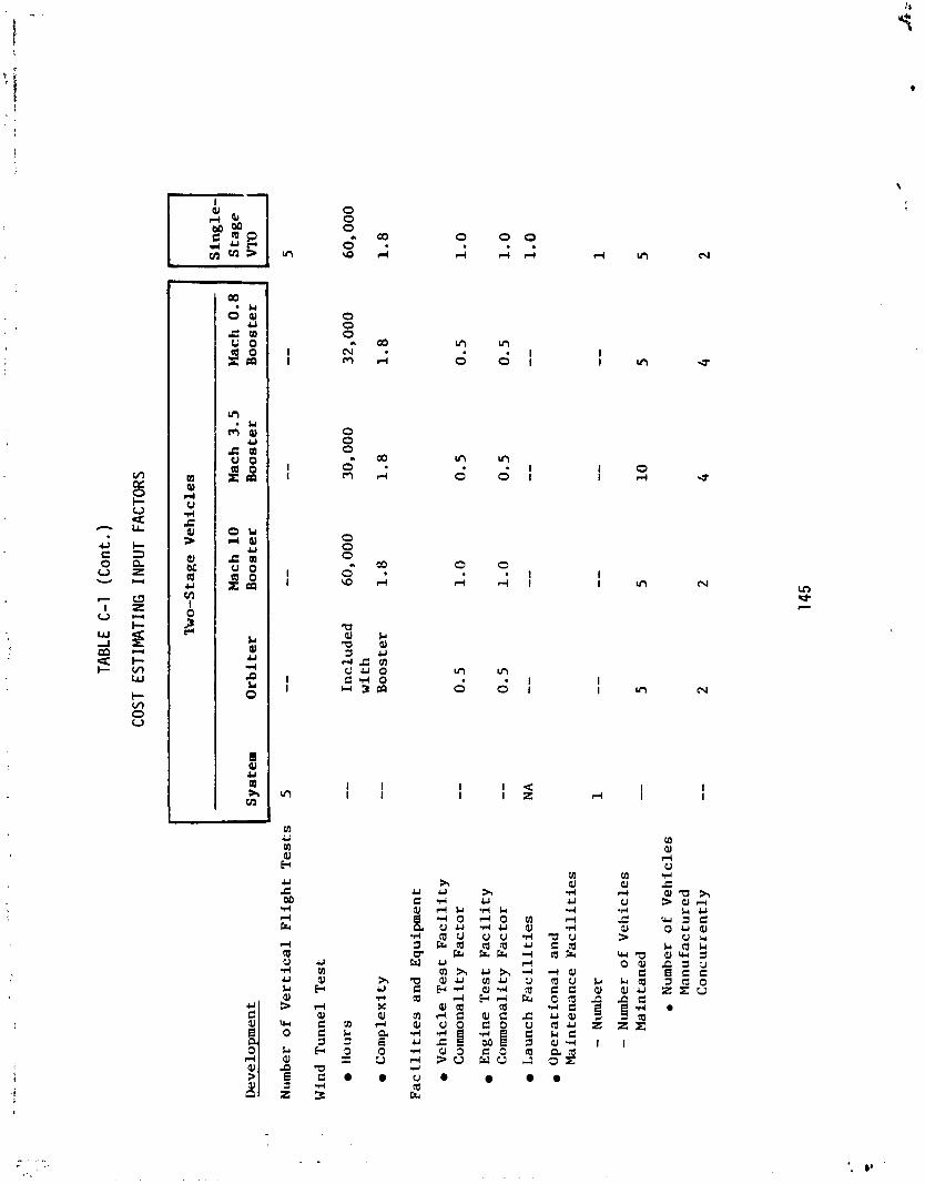
TABL
E C-
1 (C
on
t. )
COST
EST
IMA
TIN
G I
NP
UT
FACT
ORS
Sin
gle
- S
tag
e
Iko-S
ta
ge
Ve
hic
les
Mac
h 1
0
Mac
h 3
.5
Mach
0.8
S
yst
em
O
rbit
er
Bo
ost
er
Bo
ost
er
Bo
ost
er
Dev
elo
pm
ent
Num
ber
of
Ve
rtic
al
Fli
gh
t T
es
ts
5
--
--
--
--
. W
ind
Tu
nn
el
Te
st
Ho
urs
Co
mp
lex
ity
--
Inc
lud
ed
60,000
30,000
32,000
60,000
wit
h
--
Bo
ost
er
1.8
1
.8
1.8
1
.8
Fa
cil
itie
s a
nd
E
qu
ipm
ent
Ve
hic
le T
es
t F
ac
ilit
y
Co
mm
on
alit
y
Fa
cto
r
En
gin
e T
es
t F
ac
ilit
y
Co
mm
on
alit
y
Fa
cto
r
Lau
nch
F
ac
ilit
ies
Op
era
tio
na
l a
nd
M
ain
ten
an
ce
F
ac
ilit
ies
- N
umbe
r 1
- N
umbe
r o
f V
eh
icle
s M
ain
tan
ed
--
. Nu
mbe
r o
f V
eh
icle
s M
an
ufa
ctu
red
C
on
cu
rre
ntl
y
--

TABL
E C
-1
(Con
t.)
COST
EST
IMA
TIN
G I
NPU
T FA
CTOR
S
lbo
-Sta
ge
Veh
icle
s I B
S
tag
e M
ach
10
Mach
3.5
Mach
0.8
S
yst
em
Orb
iter
B
oo
ster
B
oo
ster
B
oo
ster
r
- D
evel
opm
ent
Tra
inir
g
0
Fli
gh
t C
rew
P
erso
nn
el
Gro
und
Cre
w
Per
son
nel
-
Gov
ern
men
t P
rogr
am M
anag
emen
t an
d P
erso
nn
el
(man
-yea
rs)
2100
Pro
pel
lan
t C
ost

TABL
E C-
1 (C
on
t. )
COST
ES
TIM
AiIN
G I
NPU
T FA
CTO
RS
Tw
o-S
tage
Vehicles
Mac
h 10
Mac
h 3
.5
Ela
ch
0.8
S
yst
em
O
rbit
er
Bo
ost
er
Boo
e ter
Bo
ost
er
I -
Sin
gle
- S
tag
e 6
Fir
st
Un
it C
ost
Str
uc
ture
Aer
od
yn
amic
S
urf
ac
es
Co
mp
lex
ity
F
ac
tor
- C
on
fig
ura
tio
n F
ac
tor
- M
ate
ria
l/C
on
stru
cti
on
F
ac
tor
~o
dy
/'l'
an
k S
tru
ctu
re
Co
mp
lex
ity
F
ac
tor
- C
on
fig
ura
tio
n F
ac
tor
- ~
ate
ria
l/~
on
str
uc
ti
on
F
ac
tor
- P
rop
ell
an
t F
ac
tor
0 T
her
mal
P
rote
cti
on
Sy
stem
C
om
ple
xit
y
Fa
cto
r (9
0%
p
an
el
we
igh
t;
10%
ins
ula
tio
n
we
igh
t)
--
- C
on
fig
ura
tio
n F
ac
tor
--
- ~
a te
ria
l/~
on
s
tru
c ti
on
F
ac
tor
--
0
Gu
idan
ce
and
N
av
iga
tio
n
Co
mp
lex
ity
Fa
cto
r --
~n
str
um
en
tati
on
/Pa
ne
ls
Co
mp
lex
ity
F
ac
tor
--

TABL
E C
-1
(Con
t. )
COST
E
STI
WTI
NG
IN
PUT
FACT
ORS
I T
wo-
S ta
ge
V
eh
icle
s 1 S
ing
le-
Sta
ge
\ I M
ach
10
M
ach
3.5
M
ach
0.8
S
yst
em
Or
bit
er
B
oo
ster
Bo
ost
er
Bo
ost
er
Fir
st U
nit
Co
st
Str
ucL
ure
(C
on
t.)
tly
dra
uli
c C
om
ple
xit
y F
act
or
--
1.0
1
.0
1.0
1
.0
Pro
pu
lsio
n
- R
ock
et
En
gin
e C
osp
lex
ity
F
act
or
- R
eact
ion
Co
ntr
ol
Co
mp
lex
ity
F
act
or
--
- A
ir-B
rea
thin
g
En
gin
es
Tu
rbo
jet
Com
ple
xi t
y
Fa
cto
r - -
S
cra
mje
t C
om
ple
xit
y
Fa
cto
r --
-
Dro
p T
ank
Co
mp
lex
ity
F
act
or
--

TARLE
C-1
(Con
t. )
COST
ESTIMATING
INPU
T FA
CTOR
S
I 'h
o-S
ta
ge
Veh
i ale
s
I Sin
gle
- Stage
Mac
h 10
Mac
h 3
.5
Ela
ch 0
.8
Sy
stem
O
rbit
er
Bo
ost
er
Boo
e te
r B
oo
ste
r In
ve
stm
en
t
Num
ber
of
Lau
nch
S
ite
s (
tota
l)
1
Ground
Su
pp
ort
Eq
uip
men
t (p
erc
en
t o
f RCD)
70%
--
--
--
--
70
%
Num
ber
of
Ad
dit
ion
al
Liq
uid
P
rop
ell
an
t F
ac
ilit
ies
1
Num
ber
of
New
V
eh
icle
s - -
4
Num
ber
of R&D
Ve
hic
les
Mo
dif
ied
Pro
du
cti
on
Tim
e (u
~o
ntl
ls)
--
15
Le
arn
ing
Cu
rve
- -
9 2%
Num
ber
of
Ve
hic
les
Main
tain
ed
a
t S
ite
Go
ver
nm
ent Program M
anag
emen
t (m
an-y
ears
) 1
20
0
--

r l m u m 0 0 0 0 0 0 0 0 0 d d d l d g

AERO SURFACES
Aluminum S h e e t
Alurrinum S/S/F'
T i t an ium S h e e t
T i t a n i u m S/S/F
s s steel2
L 605 A l l o y
TABLE C - 2
STRUCTURE MTER!AL/CONSTRUCTiON FACTORS
VTO - SINGLE-STAGE-TO-ORP I T
Combined f a c t o r 1 .74
BODYITANK STRUCTURE
Aluminum S h e e r
Aluminum S/S/F
T i t an ium S h e e t
T i t an ium S/S/F
S S S t e e l
Rene '41, e t c .
T H E W PROTECTION SYSTEII
Columbium
T i t a n i urn
L 605 Al loy
S S S t e e l
Rene '41, etc.
0.06
0.40
0.06
0.35
0.39 -- -
Combined f a c t o r 1 . 2 6
0.53 - Combined i ac t o r 3 . 3 3
'~k-!~, 'Jcr in~er/ t rame. ' super s t a i n l e s s s t e e l ( h i g h t e m p e r a t u r e ) .

TABLE C-2 (Cont. )
STRUCTURE WTERIAL/CONSTRUCTION FACTORS
ORBITER
AERO SURFACES
Aluminum Sheet
Alqminum S/S/F
Titanium Sheet
Titanium S/S/F
S S S t e e l
L 605 Alloy
BODY~TANK STRUCTURE
Aluminum Sheet
Almi.~um S/S/F
Titanium Sheet
Titanium S/S/F
S S S t e e l
Rene '41, e t c .
THERMAL PROTECTTO:! SYSTEM
Columbium
Titanium
L 605 Alloy
S S S t e e l
Rene '41, e t c .
0.06
0.10
0.28
0.81
0.13
0.31 - Combined f a c t o r 1.69
0.06
0.40
0.11
0.58
0.17
0.05 - Combined f a c t o r 1.37
0.53 - Combined f a c t o r 3.33

T A e L E C - 2 (Con:.!
AERO SURFACES
Aluminum Sheet
Aluminum S/S/F
Titanium Sheet
Titanium S/S/F
S S S t e e l
L 605 Alloy
BODY / TLLK STRUCTURE
STRUCTURE MATER I A L / C O N S T R U C T I ON FACTORS MACH NO. 10 BOOSTER
Aluminum Sheet
Aluminum S / S / F
Titanium Sheet
Titanium S/S/F
S S S t e e l
Rene '41, e t c .
THERMAL PROTECT J Ch SY STE?? -..
Columbium
Titanium
L 605 Allow
S S Stee l
Rene '41 e t c .
0 .03
0.10
0 . 2 8
0.92
0.07
0 . 3 1 - Combined factor 1 . 7 4
0 .06
0 .40
0 .04
0 . 35
0 .39 -.
-- Combined factor 1-26
1.38
0.37
0.31
0..53 - Combined factor 2 .59

TABLE C-2 (Cont. )
STRUCTURE MATERIALICONSTRUCTIOPi FACTORS MACH NO. 3.5 BOOSTER
AERO SURFACES
Aluminum Sheet
Aluminum S / S / F Titanium Sheet
Titanium S/S/F
S S Steel
L 605 Alloy
BODY / TANK STRUCTURE
Aluminum Sheet
Aluminum S /S/F
Titanium Sheet
Titanium S / S / F
S S Steel
Rene '41, etc.
-- - Combined factor 1.06
-- -
Combined factor 1.17

AERO SURFACES
Aluminum Sheet
Aluminum S/S/F
Titanium Sheet
Titanium S/S/F
S S Steel
L 605 Alloy
B W Y / TANK STRUCTURE
Aluminum Sheet
Aluminum S/S/F
Titanium Pheet
Titanium S/S/F
S S Steel
Rene '41, etc.
TABLE C-2 (Cont. )
STRUCTURE MATERIAL/CONSTRUCTION FACTORS
MACH NO. 0.8 BOOSTER
Combined factor 0.95
-- - Combined factor 0.99

TABLE C-3
SINGLE-STAGE-TO-ORBIT (VTO)
COST COST ELEMENT OEIICNATION 1 0181TER 1 lOOSTER SYSTEM EOS TOTAL
1000 / TOTAL ROT&€ 1 1 760.7 I 1100 / CONCEPTUAL AND OEFlNTlON PHASE 1 1 I 47.2
1110 Conceptual Studies IContmtor) 3.4
- - - - - 1130 / Other Study SUPPOR-
1140 I SEnD Contractor(J
1 1218 I Drop Tanks 1 1 I 1 -- I 1 1220 1 Propulsion ! 1 1 1 1234.5 ;
!
, 1120 / Program Definition Studies (Contnctod 1 - - - - - -
- -
1212 ( Landing Gear
1213 ( Thermal Protection S y n m
30.3
1214
1214-1
I ... F I --
I I I 317.6 I '
I I i 1230 ( Vehicle Integration 1 ' 129.5 1
6792.0 , 1 2623.1
I 999.9
- - - - -
13.5
1200 I ENGINEERING OEVELOPMENT PHASE
1210 / Air Frame
Avionics
Guidance and Navigat~on
1
1214.2 / Communications 1 1
7- - - - - - - - - - - -- -- -- - - - - -
1 1240 I Initial Tooling i I I i 303.9 I I
I
1211
547.9 1
144.8
1221 I Rocket Engines - Primaly
--
t
Stnrcture
I I
I 1 1118.0 I
1211-1
121 1-2
121 1-3
i
I 121 4-3 I Instnrmentation/Panels
1222 I I I 1 -- I I
Rocket Eng~nes - Secondary I
I
1223 1 Air4reatbing Engmes I ! I I -- I
1224 I I Orientat~on Control 1 1 i I 1 116.5 I
I I
Aerodynamic Surface
BadyITank S t ~ c t u r e
Nonintegral Tanks
117.0 1 1
1 286.1 1
1 196.4
1 803.5
11211.4 j Other
1215 1 Power Supply and Oistnbunon I 1 338.8 I 12151 ( Efwtrical Power I I 1 1 268.5
I --
1215-2
I i i -- I *
! 1 Hydraulic Powsr 70.3
418.9 ! -- 1
1 1216 Environmantal Control & Life Support
1217 Emeroencv I

TABLE C-3 (Cont.)
SINGLE-STAGE-TO-ORB IT (VTO)
COST ELEMENT OESIGNATION
1261 Ground Test 1 6 3 2 . 6
1262 I Flight Test 4 2 1 . 7
1270 ! Test Operations 1 4 1 4 . 0
1271 [ Ground Test I 1 5 7 . 0
1272 1 Flight Test 1 1 1 3 7 . 5
I I 1272.1 Horizontai I 6 8 . 2
I 1272-2 / Vertical 1 69 .3
1273 1 Wind Tunnei Test 1 1 1 1 9 . 5 .I
1280 / Facilities and Eouipment I I ! 7 5 6 . 9 . 1
1281 I Vehicle Test Facilities 1 1 I 1 2 6 . 3 1 1
1282 I Engine Test Facilities 1 1 / 1 1 9 . 9 !h I
1283 Launch Facilities I 1 7 8 . 0 I' 1284 Operational & Maintenance Facilities 1 1 4 1 . 8 1
I I 1285 I Manufacturing Facilities 7 . 6 I I
1286 ! Wind Tunnei Facilities I 1 I -- I 1287 1 Propellant Production Facilities 1 I 1 f 57.8 !
I
1288 1 Suppon Equipment 1 1 I -- i 1289
I I ! I Activation I 1 3 5 . 5 I
1 I
1290 I Training 1 1 1 1 8 . 8 / 1291 I h m n n e l I I 34 .5 1 1291-1 / Flight Crew 1 t 1 29.7 1
1291-2 / clround Crew 1 1 I 4 . 8 1 I
1292 I I Simulators and Equioment I 1 1 1 8 4 . 3 1
- - -
1300 I SYSTEM I N ~ ~ R A T I O N ENGINEE~ING / I I 1 2 1 9 . 3 1 I
I 1310 I I I I / Contractor Program Management 1 4 0 1 . 6
I ! I 1320 I SEfTO Contractor(sl ! i 1 -- i
I i 1
1400 / TECHNOLOGY SUPPORT PHASE ! -- i
I i I
1410 i Aerothermo Technology -- I
1420 I StructureIMaterial Technology 1 I I ! -- I
I 1430 j Propulsion Technology I I I -- I

TABLE C-3 (Cont. )
SINGLE-STAGE-TO-ORBIT (VTO)
I COST
. - - - -- - - --
I Operational & Maintenance Facilities I
1440
1500
I 2150 / Ground Equipment 1 1 3 9 . 5 I
ORBITER BOOSTER SYSTEM ELEMENT I NUMBER
Other Technology
GOVERNMENT PROGRAM MGMT.
EOS TOTAL COST ELEMENT DESIGNATION
2000 I TOTAL ItJVESTMENT
-- 5 7 . 8
1
- - - - -- - - - - - - -- - - - - - - -
2130 I Manufacturing Facilities 1
1 2220 ! R8'1 Vehicle Modifications 1 1 1 1 1 2 6 . 5 1 -
1
2140 1 Propellant Production Facilities 1
-- I 1 4 1 . 6
I
I
1 -- 1 1 1 1 . 6
i i I 2160 / Suopon Equipment
2340 I Additional and S u v L ~ i n p Tooling 1 1 1 -- , 2350 1 Contractor Prooram Manaaernent 1 I -- I
2 3 6 1 . 0
2200 I REUSABLE VEHICLE FLEET 1 1 1 1 2 1 9 1 . 2
2210 I New Vehicle Manufacturing I 1 1 4 2 8 . 3 1 % 2170
-- - -- -- - -- - -
2230 I Initial S p a n 1 1 I 2240 I
1 2400 i GOVERNMENT PROGRAM MGMT. I ! I i 1 8 0 . 9
1 3000 1 TOTAL OPERATIONS I , 112,460.4 ! I
I I
r j I
1 3100 / OPERATIONS 1 I 1 1 6 1 8 . 8 ! 1 3110
I I I
] bunch Operations I 1 ! 5 5 . 0
I I I 3120 / Recovery rlperationr I 2 5 . 7 ! 3130 i Command and Control i I ! ~45.6
I
, 3140 I Replacement Training I 1 i 5 0 . 6
I
I
Activation
1 4 2 . 8 / I I Sustaining Tooling I
I 45.6 1
2250 / Engineering Suppon I 1 I I 285, 1 6 2 . 3 1 -- 1
' 2260 I Contractor Program Management 1 1 1
2300 ( EXPENOABLE HARDWARE 1 1 I --
2320 . 1 Sparessupport I
2330 I
Engineering Support I 1 -
I -- !
2270 1 SEITD Contractorlsl 1

T A B L E C - 3 (Cant.)
SINGLE-STAGE-TO-ORB,IT (VTO)
-
3150 1 Facility & Equipment Maintenance 1 1 I 387.1 1 1
COST ELEMENT COST ELEMENT OESIGNATION 1 NYMI IR 1 ORBITER 800STE3 I
1 3162 1 Space-Qsed Maintenanre Operations I 1 I -- 1
I 1 159.9
227.2
3151 1 Launch & Maintenance Facilities I
3160 '
3161
I I 3170 In-Plant Engineering Support I 1 269.6 /
SYSTEM
3152
1 3180 1 Program Integration and Management I 1 1 168.5
EOS TOTAL
Ground & Support Epuiprnat I
t r I I
Vehicle Maintenance
Ground-Batad Maintenance Operations
513.7
513.7
321 1 Structure 1 i 1 678.8 1 3200
321 0
SPARES AND PROPELLANT SUPPORT
FollowOn Spares
3212 1 Thermal Protection System
1 4114 / Other 1 1 I I ! I --
I I I , i ! 4120 ! Landing Gaar I 0.3 I i i ! 4130 ! Thermal Protection System I ' 14-3.9 i
I i I 1 (140 1 Avionics ! 26.6 I
10.671.1
8645.5
3221 1 Basic Cost (Ground-lased) 1 1 --
3300 / RANGE/BASE SUPPORT 1 1 170.5
i i I 1 4141 I
Guidance and Navigation 1 12.2 1
1 1 3019.7 /
421.7 I
331.9 1 107.8 / 41.6 1
I
66.2 1
-_ ! I
$ F
3213 Rocket Engines 4 3214 Air-Breathing Engines
I I 4000
I 3215 1 Subsynems I I 1 4060.6
3216 Other I -- 3217 1 Transportation (Space-Based) I -- , 3220 / Propellants and Gases 1 2025.6 1
886.4 . --
AIR VEHICLE FIRST UNIT COST
4100 AIR FRAME ! I 4110 1 Structure I 1 41 11 1 Aerodynamic Surfaces 1 I I
I 1 41 12 / BadyITank Structure I [ 4113 1 Nonintqnl Tanks i I I 1

TABLE C-3 (Cont.)
SINGLE-STAGE-TO-ORBIT (VTO)
4142
4143
4150
4151
41 52
4160
4170
4200
4210
4220
4230
4240
4300
Communication
Innrumentation/Panels
Power Supply & Distribution
Electrical Powrr
5000 / DROP TANK FIRST UNIT COST
10.1
14.0
33.8
25.6
Hydraulic Power
Environmental Control & Life Support
Emeqency Recovery
PROPULSION
Rocket Eng~nes - Primary
Rocket Engines - Secondary
Air-Breathing Engines
Orientation Control Thrusters
INTEGRATION, ASSEMBLY, CHECKOUT, AND TEST
--
r i
- r -
o 2
-
8 . 2
19.5
-- 7 5 . 3
48 .0 -- -- 2 7 . 3
1 4 . 5

TABLE C-4
TWO-STAGE
(Subsonic Staging, Sing1 e-Booster)
~- --
I / Vehiclr Integration 1 106.3 57.4 : 158 .6
1000
1100
1110
1120
1130
1140
1 1211-4 / Other I I 7 a 1212 I Landing Gear F
1213 I Thermal Protaction System 294.6 1 I 1214 Avionics 547.9 1 140 .3 I
1240 ! Initial Tooling ' 325.2 501 .3 ! 826 .5 j
5432.6
4907.2
TOTAL ROT&E
CONCEPTUAL AN0 OEFlNTlON PHASE
Conceptual Studin (Contractor)
Program Oafinition Studies (Contractor)
Other Studv Support
S U T O Contractods)
1214-1 1 Guidanca and Navigation
1200 I ENGINEERING OEYELDPMENT PHASE
117.2 1 35.2
3159.1 1 797.3 / 9 0 2 2 . 6 ,
1210 Air Frame 1 2353.4 2842.3
-
1264.3 121 1
1211-1
121 1-2
I
I
i 3617.7 , I
1214-2
852.8 1 507.0 / 345.8 1
I
I I I
47 .2 1 4 7 . 2
3 .4 1
1211-3 1 Nonintwral Tanks
1
30.3
1 3 . 5
591.4 - - - - --
Structure
Aerodynamic Surface
BodylTank S t ~ c t u r e
Communications 1 144 .8
8340.9 -
947.4
31b. 4
633.0
20 .6 1 , 1 I . 84.5 1
I
1214-3 1 I nst~mentationiPanels 286.1 1215 / Power Supply and Distribution 250.8 , . 271.2 1 12111 1 Eiectricd Power I 199.5 i : 212.0 I I
I 1215-2 1 Hydraulic Powr 5 1 . 3 1 59 .2 1216 Environmental onn no^ L ~ i t e ~ u p p o n l 312.7 1217 / ~mergency
1 I
1218 / Orop Tanks I I 1 I I
I + 1 1220 ! Propulsion 1 242.6 1 90 .4 ' 333.0 1
I I I
1221 I Rocket Engines - Primary 1 1 2 6 . 2 :
1222 i Rocket Engines - Secondary 1 I I
I I 1 1223 1 Air-Sreathing Engines 90.4 / I 1
1224 I Orientation Control 116.k 1 I I

TABLE C-4 (Cont.)
TWO-STAGE
(Subsonic Staging, S i ngl e-Booster)
I
Ground Eauioment 58.2
COST ELEMENT NUMBER
. .
1260 Test Hardwan 968.0 1 507.3 1 1 1475.0 1
1 1271 1 Ground Test 1 137.8 1 115.9 1 I 1
COST ELEMENT OESIGNATlON 0R81TER EOOSTER
- -
1 8 7 I Proodlant Production Facilities I
1272
1272.1
1272-2
1273
1282 I Enpine T m Facilities
SYSTEM
68.2
68.2
Flight Test
Horizontal
Vertical
Wind Tunnel Test
59.9 1 59.9
EOS TOTAL
1280 1 Facilirias and Equipment
1281 I Vehicle Test Facilities I 58.3
-- - --
I -- - -
68.2
68.2
63.2 1 I
--
70.5 1
70.5 I
I 1 - 217.0
1283 1 Launch Facilitia I I
126.4
1286 I Wind Tunnel Facilities I I I 1 1
1284
1288 I Support Equipment 1 57.8 I 1
56.6
429.8 144.0
Oparaiond & Mainttnanca Facilities
700.2
I 152.5
I I 1
284.3 1 8
575.0 1
1289 I Actwanon 1 I I j 155.0 I
1290 I Training 1 77.4 i 40.6 1 34.5
1285 I Manufacturing Facilities 8-2 1 20.9
34.5 I
I 29.7
1291 / s lnonnd I
1320 / SEITD Cantracror(r) 1 1 I
1400 I TECHNOLOGY SUPPORT PHASE I I I
1 2 9 1 - 2 I Ground Crew I I 4.8
1 Simulators and Equipment [ 77.4 1 40.6 1 1292
1300 I SYSTEM INTEGRATION ENGINEERING / 177.7 i 100.2 i 6.4
1310 I Contractor Program Management 1 347.7 216.6 1 1.0.7
1291-1
I J
I 1
flight C r w
[ 1410 1 1 1 I I I Aerothermo Technolow I I
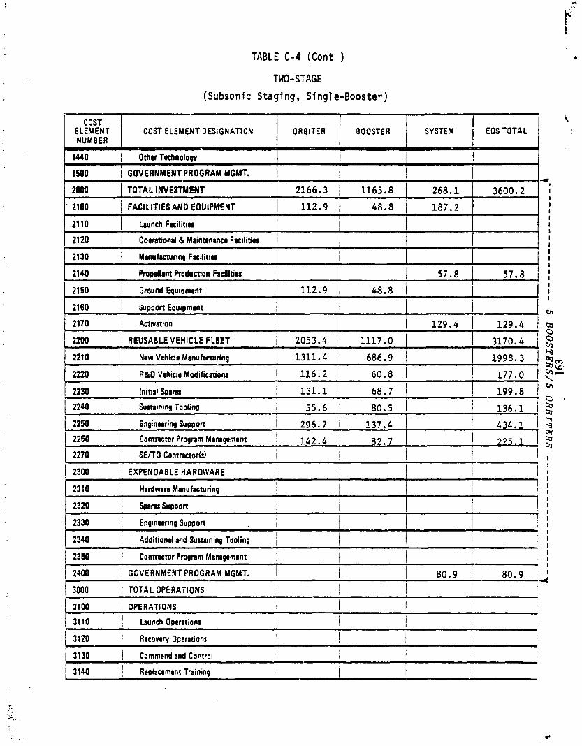
TABLE C-4 (Cant )
TWO-STAGE
(Subsonic Stag1 ng, Sing1 e-Booster)
COST \ I ELEMENT / COST ELEMENT OESIGNATION I BOOSTER I EOSTOTAL I : NUMBER 0 I
1440
1500
Othw Technology
GOVERNMENT PROGRAM MGMT.
-- - -- - - - - - - - - - - -
21 60
~4
I I
I I
I I I
I I
I
2140
2150
- --
I 57.8 1 57.8 I , ;
1 131.1 1 I 1 2230 1 Initial Suarr 68.7 1 199.8 1
1 I
3600.2
I I 2000 I TOTAL INVESTMENT
Pmpdlant Production Facilitia 1 Ground Equipment 1 112.9 48.8 1
I i hiupport Equipment
1 129.4 1 1 2 9 . 4 ,
2053.4 1 1117.0 1 3170.4
2170
221 0 I New Vehicle Manuhrturing
I 2240 I Sustaining Tooling 1 55.6 I 1 80.5 1 1 136.1 / g
2166.3
112.9 21W
21 10
I I
I Activation
FACILITIES AN0 EOUIPMENT
hunch F r i l i t i u
2200 I REUSABLEVEHICLE FLEET
L
2220 I R&0 Vh ic l r Modifications 1 116.2 1 60.8 1 177.0
1311.4
1165.8
48.8
2120 ( Oprmtiond & Mainnnancr Fa&litia
2130 I Mrnufacntring Fac l i t i r
- --
2250
268.1
187.2
686.9 1
Enginewing Suppon 1 296.7 1 137.4 1 1 434.1
1998.3 1
225.1 1 2 I I
I
1 ' 2260 1 Conmctur Program Management 1 142.4 1 82.7 1
- -- -- -
i - I - --
2320 (<am ~ u p p o n I 2330 Engin8rring suppon I I i
I 2340 ( Additional and Sustaining Tooling 1 I
-- --
1 I ( 3130 I
1 Command and Control I ! I
1 3140 I i / Replacemant Training I I
I I I
1 2310 / Hardwan Manufacturing I I 1 1 i
2270 I SEITO ~ontmctor(s) 1 I ! 2300 / EXPENOABLE HARDWARE
- -
-i j I
I I I
I ! - -- -
2350 / Contractor Pmgnm Management 1 I 1
I 1
1 2400 I GOVERNMENT PROGRAM MGMT.
I I I I
I I
80.9 I 80.9 ,
3000 1 TOTAL OPERATIONS I I I I
b
31 00 I I OPERATIONS 1 1 I
i !
1 3110 I Launch Operations I 1 1 I
/ 3120 I Recovery Operations 1 I I I !

TABLE C-4 (Cont. )
TWO-STAGE
(Subsonic Staging, Sing1 e-Booster)
I I 2140 / Pmpdlant Production Facilitia 57.8 1 57.8 1 :
-
EOS TOTAL COST I
COST ELEMENT OESlriNATlON 1 ORBITER 1 8aOSTER NUMBER
- -
SYSTEM
1440 [ Othar Tachnology
1500 I GOVERNMENT PROGRAM MGMT.
2170 ( Activation I I 1 129.4 1 129.4 1 0
2166.3
112.9
2000
21 00
2110
- - ---
21 50 ( Ground Equipment 1 112.9 ( 48.8
I I 2160 I SUPPOR Equipment
2130 I Mmufaturina Facilitia
TOTAL INVESTMENT
FACILITIES AN0 EQUIPMENT
bunch F r i l i t i a
- - I
161.7 1 I I
I
I I
2120 I Opamtiond & Mainnnanca F acil it iu
u
-- - -- - - - - -- - Q
2200 1 REUSABLE VEHICLE FLEET 1 2053.4 I 676.5 I 7 2729.9 ; $
I I I
2340 I Additiond and Sumining Tooling 1 I I
1 I
I
f I I I I I
725.3
48.8
2210 I Naw Vahidl Manufacturing
1 2300 1 EXPENDABLE HAROWARE 1 I I / I
2350 I Contractor Pmgnm Manapnnmt I ! 1 j I
1311.4 1 373.2 1 1 1684.6 Y
2310 I Hardwan Manufacturing
2320 / soarm support
141.6
268.1
187.2
I I I
141.6
3159.7
348.9
I
. 1 2 ~ 2220 R&O Vehicla Modifications 1 116.2 1 60.8 1 1 177.0 13- 2230 1 Initial Spara 1 131.1 1 37.3 1 168.4 1 crr
1 2240 1 Sustaining Tooling 55.6 1 80.5 1 136.1 I, I 2
1 1 4 0 0 1 GOVERNMENT PROGRAM MGMT. 1 1 I 80.9 1 80.9 1 ;
- ,
I I I
/ 3000 j T OTAL OPERATIONS 1 9067.1 1 551.1 / 1736.4 I 1 3100 / OPERATIONS i I I 1594. 4
1 2250
2330
11,354.6 I 1594.4 !
296.7 1 74.6 Enginwring Support
Endnoring Suppon I
1 3110 ' Launch Operations I I 1 55.0 I -. I 3120 I
75.7 I ! I Recovery Opcntions I I I -
I j / 3130 ! Command and Control 1 148.6 I
. - I i 1 3140 1 Replacsrncnt Training I I 50.6 1
I 7 1 . 12 197.5 I r n 2260 Contmmr Program Managamant 1 142 4 1 50.1
2270 I I 12 SE/TO Contractor(sl 1

TABLE C-4 (Cont,)
TWO-STAGE
(Subsonic Staging, S i ngle-Booster)
COST ELEMENT OESIGNATION
I 1 4120 1 Landing Gear 1 0.2 ! 0.9 1 I
I 1.1 1 -- - --
j 4130 j Thermal Protection System 1 133.3 I 1 I 133.3 1 / 4140 i Avioni1,r 1 26.6 1 29.7 1 I 56.3 '
I
I / 4141 Gu~dance and Navigation I 1 . 1 18.3 ; I 30.5 ! I
m cO C
--
3180
1 3200
3210
- -- - --- -
I 1 168.5 1
- -- Prognm Integration and Managemant
SPARES AN0 PROPELLANT SUPPORT
Followor: Sparm
551.1
540.3
3216
9067.1
7543.9
3211 I Structure
1 9618.2
3212 I Thrmal Protection System
1 I
1523.2 1 10.8 , 5 7 2 - 4 . - 7 1 10.8
Other
745.4 -%
I
. 60.8 1 I
2797.2 1 280.7 1
I 261.5
3213
1
I I
t 3217
I I Transportation (Spa~bBased)
3220 1 Propallrntr and Gucr
3221 1 Basic Con (Gromd-Bated)
I Rocket Engines
I 3222 1 Trnspomtion Ci~a i:pac#,Bastdl I
3214 1 Air-Rreath~ng Englnts
3215 1 Subsynems
I I
3720.6 218.0 1
142.0
590.0 / 477.1
214.9 1 146.8 1
3300 / RANBEIBASE SUPPORT I 1 1 142.0
41 12 1 BodyRank Structure 1 45.1 1 I 68.0 ! - I I 1 I 41 13 1 N m i n t r g d Tanks
1
I
387.2 1 202.81
322.9 1 13.2
118.4 1 96.5 -
4000 j AIR VEHICLE FIRST UNIT COST
41 1 1 1 Aerody nemic Surfaces 1 73.3 / 73.l 1 23.0 1
4100 AIR FRAME
4110 , S t ~ ~ t ~ r 8

TABLE C-4 (Cont. )
TWO-STAGE
(Subsonic Staging, S ingle- Booster)
4142
4143 h
4150
4151
Communication
InrtrumcmdonlPandt
Pomr Supply & Distribution
Electrid P o w
41 52
4160
4170
4200
-
4300
5000
- - -
5 . 9
1 9 . 5
- - - - -- - - - - - - - -
Hydnulic Powr
Environmcntd Control & Lifc Support
Emcrptncy Rccovnry
PROPULSION
6 . 4
8 . 0
2 4 . 9
1 9 . 0
I
-
INTEGRATION, ASSEMBLY, CHECKOUT, A N 0 TEST
DROP TANK FIRST UXIT CCST
6 . 9
4210
4220
3 . 5
7 . 9
2 7 . 1
20 .2
1 2 . 8
1 9 . 5
Rockot Engines - Primary
Rockn Engines - brconbry
1 4 . 2
13 .6
21 .9
5 ? . 0
3 9 . 2
9 0 . 3
22 . S
5 0 . 1
2 2 . 8
r
Airhath ing Engines
Orinntation Control Thrusten
4 0 . 2
8 . 4
4 0 . 2
2 7 . 3 2 7 . 3
I %
4 0 . 2 1
2 2 . 6 -

TABLE C-5
TWO-STAGE
(Subsonic Staging, Twi n-Boas t e r ) i
1 E L 1 COST EISIENT OEIICIATICN NUMBES
1214-1 1 'hidmcr and Ndqatioq I I 1 1 I
I 12142 Communications I I 1
- -- - - - I
1211 I ~tructurr 4 8 3 . 5 1 I 1211-1 I Arrodynrmic Surfacr I i
I -
I 4
/ 1215 I Power Supp!~ and Distribution I 1 1 3 4 . 7 1 I I - 1 1 2 1 ~ I E l m r i d Pomr I I I I i I
ORBITER
1211.2
I 1218 I I Orop Tanks I I ! ! I
BPOSTER I I SYSTEM 1 IOSTOTAL
(one.) 1 I
Bodyflank S t ~ n u n 2 3 9 . 7 1 1 I
I
2 0 7 7 . 4 1 7 9 7 . 3 , 8 3 0 7 . 3
I
!
r
lo00 I TOTAL ROT&€
'1211-3 1 Nonmtqnl Tank
112114 1 Othrr
- - - - - - - - -
I I 1 1221 Rocka E n p m - Pnrnary I I 1 1222
5432.6
1200 I ENGINEERING OEVELOPMENT PHASE
1 f 1 I
I Rockrt E n q m - Secondary
i 2077 .4 / I I
I I
1100
Ill0
1120
I 1 1210 1 Air Fnmr I I 7 5 8 . 5 1 I 1
- 1212 1 landing Grrr I 1 1 1
CONCEPTUAL AN0 OEFINTION PHASE
Concuptud Studies (Contnctor)
Program Orfinition Studiir (L'ontmtorl -
1213 ( Thrnnd Pmtmion Systrm
- i / 1223 I Air-enrthtng Engma 1 I
-.
1130 1 Odln Study SUWOII
1140 I SElfO Contnctodl
i 1 I
i 1224 I Onentatron Control I
- 1214 I ,\nonics 1 1 1 4 0 . 3 1 1
I -7
1
I ! I
I 1 1230 I Vehlclr lnt:qnt~on 3 0 . 9

1 -
. . . . . . - " - L r * P I !
'TABLE C-5 (Cont. )
TWO-STAGE.
(Subsonic Staging, Twi n-Boos ter)
1250 Ground Equipmant 37.2 1 1 1260
1261
1262
-
Honzc ~tal 1 Venica
I 1 1286 I h~nd Tunnel %ilities i I I I I i
- -
95.9 1 I
I
I i;Aitier and Equipnent I 1 127.9 1 1
! 1287 ' Propellant Produrnon Facilities 1 1 1 I I
Test Hardwan
Ground Test
Flight Tan
Wind T u n d Test 1 1 I 1
Vehicle Tert Facilities
Engine f e n Facrlitia
1290 1 I I I I Trainmg I 24.6 ! I j t
1291 1 Personnel 1 1 1 I 1
1 63.2 1 I 1 I
I 60.0 1 1 I co
I I I 1291-1 1 Flight Crm I ! 1- 1291-2 I Ground Crew I I 1 I I
I I 24.6 1 I 1292 / Simulators and Equ~pment !
1300 / SYSTEM INTEGRATION ENGINEERING I 65.4 1 I I i I
1310 / Contractor Program Management 1 j 1 3 7 , 7 1 1 !
1270
352.8
368.7
245.8
1370 SElTD Contrac?or(s) 1 1 ! ! 1409 1 TECHNOLOGY SUPPORT PHASE f ! I I
i I I 1410 1 Aerotherma Technology I - I
1420 ! StrucrweiMarerial Technology I t I
L~ / Prooutsion Technolow I I 1 I
Test Oprrations
1
200.6
105.1
I I Launch Facilities
1284 1 Operational & Msinmnancr Facilities
A--
1271 I Ground Test
1272 I Flight Ten
I
1
I i cD ?
i
. ! I I
9 5 . 5 1 I
1285 ( " ~nufarnrrinp Fsci~ities 1 ! 4.7 ' I

TABLE C-5 (Cont. )
TWO-STAGE
(Subsonic Staging, Twin-Booster)
2000 1 TOTAL INVESTMENT 1 2166 .3 7 3 0 . 8 2 6 8 . 1 1 3165 .2
2100 FACILITIES AND EQUIPMENT 2 6 . 0
2110 Launch Facilities
2120 1 O~en t i ond & Maintens. cr Facilities
-- - -- - - -- -- -
2140 I Pmpellant Pmduaion Fac~l i t iu I
I 1
21 50 I Ground Equipment 2 6 . 0 1 21 60 Support Equipment 1 2170 Activation
I I
2200 I REUSABLE VEHICLE FLEET I 1 704.8 1 I I 221 0 1 New Vehicle Manufamring 1 I 1 416.3 1 I
I
2220 I R&D Vehicle Modifications 73 .7 1 1 2230 I ln~t ial S ~ a m I I 41.6 1 1 I
1 2240 ! Sustaining Tooling
-- - -- - -
2160 I Conrractor Program ~anagerner;t 52.2 1 I 1 2270 ( SE/TO Contranods, 1 1 I
I
i I 1 I 1
( 2300 / EXPENOABLE HAROWARE 1 I
-- -- -- - -
I -
2330 I I 1 Engineering Suppon I I
2340 I Additiond and Svminlng Tooling 1 I 2150
I I
I Contractor Pmgram Management , -----;
1 I I I 1 !
I 1 2400 I GOVERNMCNT PROGRAM MGMT. i 1 I I I
I ! 4
1 3000 I TOTAL OPERATIONS 1 9067.1 1 412.1 j 1 7 3 6 . 4 1 11215.6 i - - - -- - - -- -- -
i 3100 I OPERATIONS I I I I ; 3110 I I I 1 Launch Operat~ons I
1 3120 j Recovely Opet,oons 1 I I
3130 I Command and Control , I I
"- I i 1 3140
I
Replacement Traminq I I 1
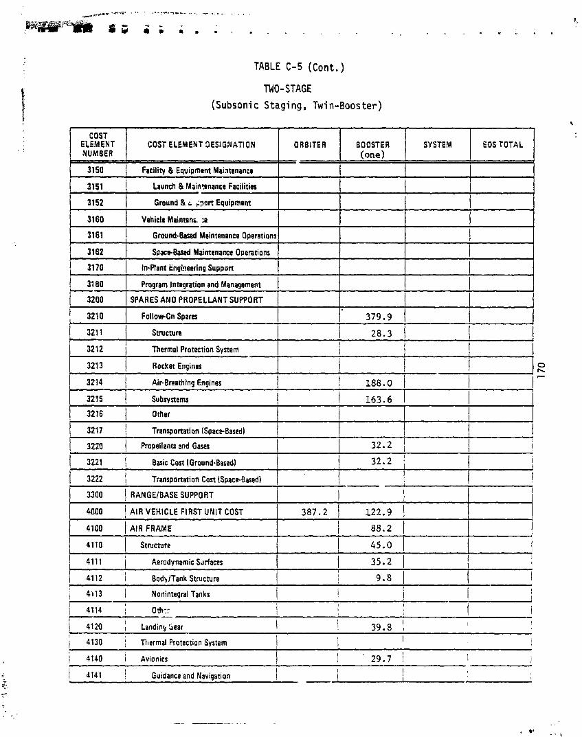
TABLE C-5 (Cont.)
TWO-STAGE
(Subsonic Staging , Twi n-Boos ter)
COST COST ELEMENT OESlGNATlON / ORBITER I BOOSTER
(one)
- - - - - -
1 3162 1 ~pac+0ased Maintenance Operations 1
SYSTEM / I O I T O T A L I
Program Integration and Management 1 ! 1 SPARES AN0 PROPELLANT SUPPORT 1 1 I
I
3150 ( Facility & Equipment Mai~tenance
3151 ( Launch & Main?crnance Facilities
3210 1 FollowCn Spares I 1' 3 7 9 . 9 I i I
3152
3160
3213 1 Rocket Ensines 1 1 I 3214 Air-Breathing Engines 188.0 / I I ' - 3215 Subsystems 1 1 6 3 . 6 1 I
Ground & ; ;?art Equipment
Vehicle Mainten;. :e
3161 1 Ground-Based Maintenance Operations
1 3220 1 Propellants and Gases I 1 3 2 . 2 1 1 1
3216 1 Other
3217 1 Transportation (Space-Based) 1 I 1 I I
i~ - - - - - - I I 1 4140 1 Avionics 1 ' 29.7 1 I 1 - ! j f 4141 i Guidance and Navigation I - I
- - -- - -
( 3221 Basic Cost 1Ground-Based) 1 3 2 . 2 1 3222 Transportation Cost (Space-Based) I I 1
I 3300 / RANGEIBASE SUPPORT i I 1 2 2 . 9 / I 4000 / AIR VEHICLE FIRST UNIT COST 3 8 7 . 2
4100 I AIR FRAME
4110 Structure
I 8 8 . 2 1 1 45.0 1
1 i
41 1 1 1 Aerodynamic Sdrfxes I 35.2 1 I I
I I
I 4112 / BodklTank Structure i 9 . 8 1 I
r 1 4.113 ' I Nonintegal Tanks ! ! 1 t
I
4114; ottlY --- I I I I I i i I I I ! 3 9 . 8 I
I 4120 Landing Sear I I
1 4130 ; Thermal Protection System 1 \ I /

TABLE C-5 (Cont . )
TWO- STAGE
(Subsonic Staging, Twi n-Booster)
COST ELEMENT COST ELEMENT OESIGNATION SYSTEM EOS TOTAL / YUM8EI 1
4142 Communication
4143 InstnrmentationlPaneIs
4150 Power Supply & Oistribution 13.5
4151 Electri J Powr
41 52
4160
4170
4200
4210
4220
Hydraulic Power
Environmental Control & Life Suppon
Emergency Recovery
PROPULSION
Rocket Engines - Primary
Rocket Engines - Secondary
4230
4240
2 8 . 9
I I I I I
Air-Breathing Engines
Orientation Control Thrusters
4300 5 . 8
INTEGRATION, ASSEMBLY, CHECKOUT, AND TEST
L
P-
h F

TABLE C-6
TWO-STAGE (Supersonic Staging)
. \
COST ELEMENT COST ELEMENT OESlGNATlON ORBITER BOOSTER SYSTEM EOS TOTAL NUMBER
I 1000 I TOTAL ROT&E [ 4 7 6 3 . 7 1 3 3 8 6 . 4 1 7 6 0 . 3 1 8 9 1 0 . 4 1 !
1100 I CONCEPTUAL AN0 OEFINTION PHASE I 1110
1120
1130
1140
1 . 4 7 . 2 1 4 7 . 2
I Conceptual Studies (Contractor)
Program Oafinition Studies (Contractor)
other Study u p p o r t
SEnO Contractor(4
1200
- - - - - -- -- - - -- -- - - - 1211-2 1 Bodynank Structure I 6 4 0 . 9 / 3 8 6 . 3 1 - - - !
( 1213 1 Thermal Protection System 1 274 .9 1 1 1 !
3 . 4
3 0 . 3
1 3 . 5
4 2 7 9 . 0 ENGINEERING DEVELOPMENT PHASE
1211-3
1211-4 I Other
- -
I 1214 I Avionics
3 1 1 1 . 2 1 5 4 7 . 4 1 7 9 3 7 . 6
I I 1 IN
9 7 3 . 0 1 1 3 2 5 3 . 6
6 9 8 . 0 1 I
, 1210 I Air Frame 1 2280 .6
I Nonintegral Tanks
, 1212 f Landing Gear 1 1 1 I$
I I I 1 1222 Rocket Engines - Secondary I ! I
I
121 1 I Shuctura
I I 1 I
( 1223 I Air-Breathing Engines 1 ! 6 9 2 . 8 i
1 1224 1 Orientation Control 1 1 1 6 . 4 1 I 1 I I
( 1230 --- / Veh~cle Integration I 4 2 . 0 1 5 2 . 8 1 9 4 . 8
9 2 8 . 1
-
1 1
- - -- - -- -- - --- - -
1214-1 / Guidance and Navigation 1 1 1 7 . 2 / 3 5 . 2
1240 ! ln~t ial Tooling 1 3 7 1 . 0 i 3 6 0 . 6 I I
7 3 1 . 6
2 8 7 . 2 , I 511.7 / I 1 121 1-1
I 1214-2 1 Communications
Aerodynamic Surface
1 4 4 . 8 1 2 0 . 6
I 1214-3 - Inst~mentation/Panelr
1215 1 Power Supply and Oinribution
2 8 6 . 1 1 8 4 . 5 1 2 1 7 . 8
121 5-1 1 Electrical Power 1 1 7 6 . 7
134 .7 1 1 0 2 . 5 1 I 1
3 2 . 2 4 1 . 1
1216
1215-2 I I Environmental Control 8 Life SUPPOR~ 312.7 1
Hydraulic Powrr
J
1
1217 Eme lency 1 1218 1 Orop Tanks I
1 1220 I Propulsm 1 242 .6 1 6 9 2 . 8 1 1 9 3 5 . 4
i 1221 I I Rorket Ensines - Primarv ! 1 2 6 . 2 1 1 1 !
1 I I

TABLE C-6 (Cont. )
TWO-STAGE (Supersonic Staqi ng )
COST ELEMENT COST ELEMENT OESIGNATION ORBITER BOOSTER SYSTEM EOS TOTAL NUMBER (one>
. . 1
1260
1261
1262
1270
I
660.8 1 1 1497.8
- - - - 1271 / Gmund T a 10 9 T3
I I 1273 I Wind Tunnel Test
12b0 / Facilitie and Equipment 1 131.1 1 129.1
1288 I I support Equipment I 1 i I i
- - - -
95.9
68.2
74.6 1 368.2 1 628.6
' 1283 I Launch Facilities
1284 1 Oprrationd & Maintensnca Facilities
1285 I Manufacturing Facii it ir
1286 ( Wind Tunnel Facilities
I I I 1289 Activation ! I 136.2 1 1
Ten Hardware
486.3
283.2 1
- - - - - -
I 70.1 1 68.2
68.2
1272 I Flight Test
1 , -
1 1 - ! I 174.2 1
13.0 1 5.9 1 f I 1 1 1 1
I I
1290 I Training 1 67.0 1 37.8 1 34.5 1 I 139.3 i
837.0
377.6
164.1
68.2 1 1 i
I 70.1 1 1272-2 1 Vertical 1 1272-1
1287 I Propellant Producnon Facilities I I 1 57.8 1 t j
1291-1 Flight Crew 1 I 29.7 1 I
144.7
Horizontal
58.3 1 63.2 ( 1281
I
1282 1 Engine Ten Facihiln 1 60.0 1 60.0 1 1 1 - Vehicle Ten Facilities
- -- -- --
I SYSTEM INTEGRATION ENGINEERING 1 164.8 ' 92.6 I 9.0 1 266.4 I I
Ground T m
Flight Test
1291-2 / Ground Crew
-- - - - - - - - - - - - --
1310 I Contractor Program Management I 319.9 182.7 i 15.1 r 517.7 1 I I 1
1320 I SE/TO Contractorts) 1 I I 1 I
1
1400 / TECHNOLOGY SUPPORT PHASE 1 ! I I I r
502.2
334.8
I i 1 1410 1 Aerotharrno Technoloav I
Test Opemions 1 177.5
. I i
I 1292 i Simulaton and Equipment ' I 67.0 1 37.8 1 1 !
1 I 4.8 1

TABLE C-6 (Cont.)
TWO-STAGE
(Supersonic Staging )
COST ELEMENT NUMBER
1 2120 1 Onerational & Maintenance Facrlities 1 1 1 1 1 !
ORBITER COST ELEMENT OESIGNATION
- lh0 1 Othtr Technology
21 00 / FACILITIES AN0 EPUIPMFNT
1 141.6 1500
1 2170 -
1 Activation
9 0 OSTE R
141.6 GOVERNMENT PROGRAM MGMT.
149.7
2000 1 TOTAL INVESTMENT
I 2110 I Launch Fa:ilitiet
2130 1 Manufacturing Facilities 1 I 21 40 I Ropellant Production Facilities
I
2210 / New Vehicle Manufacturing 1 1186.5 1 668.61 I h Y h b
SYSTEM
1989.2
25.4
I I I I
1 I / I I
21 50 / Ground Equiement
1 , 2200 1 REUSABLE VEHICLE FLEET 1 1839.5 / 1103.0) / 2942.5
EOS TOTAL
1 4 1128.4 1 278.8 1 3396.4 1 1
I
1 57.8 1 25.4 1 i 149.7
6 2
- -
1 i240 - / Sustaining Tooling
I I
197.9 1 373.0
I I I I
2220 ! R&O Vehicln Modifica?ions
2230 1 Initial Soara
I
2260 1 Contractor Program Management 136.2 1 61.7 1 1 I ' I Lq : 2270 ( SEnO Contnctor(J I I I -
I 1
1 2300 I EXPENOABLE HAROWARE 1 1
j
105.1 / 118.4 / ! I?: 118.7 1 66.9 1 1 I
- - -- I
b i I 2310 1 hrdware Manufacturing i I I i f I I I I
I 2320 . ( Sparer Support I !
I I
2350 1 Contractor PI- .ram Management 1 I i I I
! I
I I
I 2400 1 GOVERNMENT PROGRAM MGMT. 1 I 80.9 1 80.9 i 1 4
1 2330 ( Engineering Support 1 1 1 I f
1 3000 I TOTAL OPERATIONS ! 1 1 1 I
I
--
I I I I 1 3100 i OPERATIONS I
I I I
1 i i 1 3110 / Launch Operations I 1 I
1 3120 i Recovery Operations
I
I 1 3130 1 Command and Control I !
!
[-3;0 I Replacmwnt Training 1 1 I I
2340 I Additional and Sustaining Tooling 1 !

TABLE C-6 (Cont. j
TWO- STAGE
(Supersonic Staging)
COST ELEMEhT OESlGNATlON
4
2000 TOTAL INVESTMENT 1989.2 ' 14i7.3 278.8 1 4185.3
' 2100 FACl LlTlES AN0 EOUIPNNT 149.7 25.4 . 197.9 373.0
2110 Launch Facilities
2120 Opemiond & Maintenance Facilitia I I -- - - - - - - -
- - 1 Manufacturing Facilities -
2130 -r I
I
-
2140 Propdlant Pmduct~on Facilities j 57.8 I
2150 / Ground Equipment 149.7 25.4 / 1 21 60 Support Equipment 1 2170 I Activation 1 140.1 /
i - I
I 2200 1 REusAeLE VEHICLE: FLEET I 1839.5 i 1891.9 i I 3731.4i -- - -- 1 2210 p - / New Vlhicl( Manufacturing - 7 1 1 8 6 . 5 1 1230.51
2220 R&D Vehicla Modificat~ons 105.1 1 118.4 1 1 I I
I
2230 , Initial Spares 1 1 1 8 . 7 , 123.1 1 I I
2240 I
Sustainmg Tooling 1 55.71 33.7 1 I I
1 2250 1 E qlnsenng Support 237.3 1 246.1 1 I I
2260 ( Contractor Program Management 136.2 1 140.1 ! 1 2270 SElTD Contrsctor(si I 1 I I
I
1 2300 1 EXPENDABLE HARDWARE 1 I I I
I 1 I
231 0 / Hardware Manuhctunng 1 I I
2320 j S ~ ~ ~ S U P P ~ ~ ~ I I *
I I
2330 Engnaanng Support 1 I I
I 1 2340 / Additional and Sustaining h o l i q I I 1 2350 1 Ccntractor Proslam Manaaament I 1 I 1 I
,
/ 2400 1 GOVERNMiNT PROGRAM MGMT. ! 1 1 80.9 1 80.9 I
3000 / TOTAL OPERATIO',S ( 7890.0 I , ..- - 769.8 1 1'29.1 / 10,389.8 1 I I 4
1 3100 1 OPERATIONS I I j 158?.1 ! 1587.1 ,
I ! I I I
1 3110 / Launch Operations I 55.0 1 ! -- ! 3120 ; Recovery Operations ! 35.7 1 I I i 1 3130 j Command and Control ! i I 148.6 ' - , 3160 I I ,
1 I Replacement Training 1126 .-

I . . . . . . .
TABLE C-6 (Cont. )
TWO-STAGE
(Supersonic Stag ing)
1 COST I I I I 1 I COST ELEMENT OESiGNATION I ORBITER I 8OOSTER I SYSTEM I EosToTAL I
~ - -~ -- -- - - - - - - -
3150 ( Facility & Equipment Maintenance 355.4 1 3151 1 Launch & Maintenance Facilities I 87.1
-
3180 / Program Integration and Management
3200 ! SPARES AND PROPELLANT SUPPORT
I 3210 1 FollovrOn S~ares
I i 1 41 12 j BodylTank Structure I 46.4 I 32.8 1
3152
3160
1 31 70 1 In-Plant Engineehp Support I I 1 269.6 1 1
-
Ground & Support Equipment
Vehicle Maintenance
- - - -
7890.9
3211 1 ~ t r u c t u n
3212 1 Thermal Protection System
268.3
53.3.7
513.7 3161 / Ground.Blud Maintenance Operations
3162 1 Space4as.d Maintenance Operations
628.9 1 46.6 / 2362.9
i
280.7 321 3
I I I 41 13 / Nonintegral Tanks I
4114 i Other I I I
1 414: I Guidance and Navigation I 12.2 1 18.1 1 1
6897.8 1' 1076.6 1 I
- - - - - -- -
769.8
'4 Rocket Engines
I
I 1
- - - - - - - --
1 4120 Landing Gear 1 0.3 1 0.3 1 I I 4130 I Thermal Protectioc System ! 114.3 I 1 I I
- --
168.5 ! I 8660.7
3222 Transportation Cost (Spacelasedl I
I
1 4140 i Avionics
3214
3215
142.0 3300 1 RANtiE/RASE SUPPORT
I
!-= I 1
I - I
Air-Breathing Engines
Subsystems
411.8
3599.8 1 166.6
--I 142.0 I 1 I
26.6 1 29.7 1 I
3216 / Other
3217 1 Transportation (SpaccBandl
~220 1 Propellants and Gases
3221 1 Basic Cost (Ground4ased)
1018.6
1018.6
I 4000 1 AIR VEHICLE FIRST UNIT COST
4100 / AIR FRAME
144.8
144.8
/ 4110 Structure
1 4111 Aerodynamic Surfaces
350.3 197.4 1 295.6 1 126.8 / 113.3
66.9 1 50.2 1 83.0 / 1

TABLE C-6 (Cont. )
TWO-STAGE (Supersonic Staging)
1
COST ELEMENT OESIGNATION
4142
4143
41 50
4151
41 52
4160 L
4170
4200
4210
4220 v
4230
4240
.k A 92% learning curve was used
Communication
IndrumentationlPandr
P o w Supply & Oisrribution
Electrial P o w r
5000 / OROP TANK FIRST UNIT COST I I
! I I
to determine venic le cost i n calculat ing total
-
Hydraulic Pomr
Environmental Control & Life Suppon
Emergency Recoveq
PROPULSION
Rocket Engines - Primary
Rocket Engines - Secondary
Air-Breathing Engines
Orientatioi~ Control Thrusters
-
6.4
8.0
21.6
16.9
4300 1 INTEGRATIONf ASSEMBLYf CHECKOUT, AND TEST
3.5
7.9
13.5
9.8 -
4.7
19.5
42.5
15.2
27.3
12.2 7.3
-
-
-
- - - 3.7
63.3
63.3
-
- -

TABLE C-7
TWO-STAGE
(Hypersonic Staging)
I
COST ELEMENT NUMBER
1000
1100
1110
1 l?O
1130
COST ELEMENT OESIGlVATlON
8700.7 TOTAL R ~ T & E 4179.8
CONCEPTUAL AND OEFINTION PHASE 1 Conceptud Studia (Contractor)
Program Ovfinition Studirr (Contractor)
Other Study Support
- --
649.7 12,366.4
4276.7
1
' 7928.2
2483.3
1776.8
737.0
1039.8
-
1 200 1 ENGINEERING OEVELOPMENT PHASE 7 3788.5
-- - --
I I I
2 I I"-
- - - - - - -- - -- 12114 1 Ottlrr
~ --
1213 I Thmnd Protection System ( 178.8 290.3 1 /
ORBITER BOOSTER I
1212
1214
1214-1
1214-2
1214-3
EOS TOTAL
' 728.8 / 13,242.9
1793.4
5b8.2
122 .6
445.6
I 1 ! I
1210
1211
121 1.3
I 1 lading Grar
47.2
3.4
30.3
13.5
Air Framr
Strt m r r
Nonintrgnl Tanks
47.2
.
1 1 I
I
Avionics 1 547.9 / 140.3
121 1.1
121 1-2
Inrt~mtntrtionlPanels I I 286.1 1 84.5 1 3
1
i
Guidano and Navigation
Communications
1215 I Powr Supply and Oinribution -- I 121s: 1 Elwried Power
Armdynamic Surfao
Bodyflank Strucrurr
117.2 1 35.2
144 .8 1 20.6
185 .8 1 275.9 1 1 5 2 . 6 1 205.8
1218 1 Orop Tanb I
1215-2
1216
I 1
I 1
Hydraulic Powr 13.2 / 70.1
1220 1 Propulsion 1 609.0 1 1817.2
Environnntd Control & Life Support
1217 I ~rnwgrncy
2059.8
312.7 1 I
1221 I Rockat Enpinr - Primary 1 1 2 6 . 2 1 I ! I I
I 1222 / Air4reathinp Engines - Secondary 1 1 6 9 2 . 8 1 1 !
1 1223 I Air-Breathing Engines I 1 1124.4 1 j 1 1 1224 Orientation Control 116.4 i i !
I I 1230 I
! Vehicl~ lntegratio~ -- .. 83.9 ! 135.7 / 219.6
1240 1 Initial Tooling 1 2 3 2 . 4 1 715 .6 1 1 948.0 ; I

TABLE C - 7 (Cont, )
TMO-STAGE
(Hypersoni c Staging)
COST COST ELEMEHT OESlGNATlON I ORBITER
I 1
BOOSTER
1250 Ground Equipment
SYSTEM I I EoSToTAL
1 202.6
1260 1 619 .0
1262
-- - - - - - - - -- -
1281 1 Vehiclr Ten Fac~lities 1 58 .3 / 1 2 6 . 3 1 1 1 1282 I Engine Ten Facilities ( 6 0 . 0 1 1 1 9 . 9 1 1 I Q,
1 9 5 6 . 3 1 1 2575 .3 J
-- - -
I-- - -
1283 iu..h= I PI 1 I L
1284 I Op@mond & Mamnnmce h c ~ l i t ~ e r / I i 1 191.8 - 1 1 I
1285 I Manufacturing Faerlitios 1 4 . 2 1 1 0 . 7 1 1 1286 i Wind Tunnd Fac~iitres 1 1 1 I
I
Ten Hardmn
Right Tat
6 8 . 2 68 .2 1 I i I
1287 I Propellutt Pmdurrion Facilities I I 1 5 7 . 8 1 I I - i
I
1261 I Ground Ten 1 371.4
1270 1 Ten Operations
1272- 1
I 1288 1 Support Equipment I I I I i
247.6
Horizontal
1272.2 1 Vertical 1
- I 1291.2 I
I Ground Crew
1173 .8 1 782.5 1
1 5 9 . 2
I 8 4 . 0 1 1
1 1292 1 Simulators and Equioment 1 49 .5 / 1 5 6 . 5 1 I
I I
- - -- -- - - - 1310 I Contrstor Prognm Management i 255.4 490 .8 1 2 0 . 0 1 7 6 6 . 2 -
1320 SERO Contractor(si I 1 I i
1400 1 TECHNOLOGY SUPPORT PHASE I 1 I I j
L -.
255.5 - 1 6 8 . 2 1 84 .0 1 I
1271
686 .4 323.7
I I
122 .5 1 411.7 / 7 9 1 . 1 1 1273 1 Wind T unnel Test
203.5
Ground Tat
1280
9 1 . 0
1272 i Fii#t T~
Facilitiu and Eauioment
68 .2

TABLE C-7 (~ o n t . j
TWO-STAGE
(Hypersonic Stag1 ng )
COST ELEMENT OESlGNATlON I ORBITER I BuOSTER 1 SY:?EM I EOSTOTAL I I
I 20OG TOTAL INVESTMENT 1379.1 2455.6 1 257.1 1 4091.8
I 2100 1 FACILITIES AN0 EQUIPM€NT I 83.7 6 4 . 3 1 176.2 1 324.;
1 SO0 ) GOVERNMENT PROGRAM MGMT. 1 I 1 1
- -
2130 1 M m u f m u r i q Fwilitict I 1 1 2 1 4 ( Pmpdlurt Production Flsditirr I 57 .8 1 I
I I
I 57.8 1
I 2150 ( Ground Equipment I 83.7 6 4 . 3 ! l i 8 . 0 (
I
1 2180 ( Support Equipment 1 I
1 2170 Activation 1 I 1 118.4 1 I
I 1 2200 1 REUSABLE VEHlCiE FLEET 1 1295.4 1 2391.3 1 1 3686.7 I
1 2210 ( New V d i e l t Manufacturing 838.6 1 1440.1 i 1 2278.7 2220 / R&O V & C ~ Uodif iadrns 1 7 4 . 3 1 234.6 / 1 3T;g.l - -4 -3
( 2230 ! initial s p u n 1 83 .9 I 1 4 4 . 0 i 1 2 2 7 : 1 --- a . ..- 1 2240 Sustaining T OG, ..cg I I I I
I 34.9 1 107 .3 . I I<.. -1- ..
1 2250 1 Enpincrrinp Suppon 1 167.7 1 288.0 1 I 1 'LO 1 Contnctor Program Maruqarnent 1 I
I --YL -.: 9 6 . 0 1 177 .1 1 , 27a: ,.-?
I L 2270 ) SWD ~ontnctods) 1 -- / 2300 I EXPENDABLE HARDWARE 1 I !
I
2310 I I ! i I H8rdwm Man@*racturinq I I I
I
a
-- -
2320 / &am ~ u p ~ a n -
2330 1 Enginnring Suppon 1 I
h 3 5 0 - -
I I I I I Cocnwtor Program Management I
/ 240U I ! I I I GOVERNMENT PROGRAM MGMT. I 80.9 1 8 0 . 9
I I I 3000 I TOTAl OPERATIONS I I I
s
1 3100 ' OPERATIONS 1 I I I I I
i 1 3110 I I I 1 / Launch Opent~ons I I I
I - 1 3120 I Recovacy Ouerat~onr 1 , I
1 I
I I I ! 1 j 3130 ! Command and Control I

TABLE C - 7 (Cont. )
TWO-STAGE
(Hypersonf c Stag i ng)
I 1500 1 SOVE RNMENT PROGAA4 MGMT. I ! / 1 4 1 . 6 1 1 4 1 . 6 1
COST ELEMENT COST ELEME3T DESIGNATION / NUMlER 1
'E / TOTAL INVESTNENT 1 1 3 7 9 . 1 4 1 5 4 . 8 1 2 5 7 . 1 1 5 7 9 1 . 0
kkCILI7IES AN0 EQUIP?;FENT 83 .7 6 4 . 3 1 1 7 6 . 2 324 .2
21 10 Launch F u i l i t i u ! ! I
I I Oprcltiond & Mabtat'ar, I Faeilitie
I
I -.. - i 1 I
1 2130 / M m u f m n n q Wi\,, I i I I
2140 / Pmpdlant Produa~an Frriittas 1 I 5 7 . 8 1 5 7 . 8 1 I 1
21 50 I Ground E q u ~ p w n t 83 .7 1 6 4 . 3 1 I 1 4 8 . 0 1 -- I 2160 1 Support Equipnwt i I i - i -
217C I Activation 1 I ' I 1 1 8 . 4 1 1 1 8 . 4 ; I
I I 2200 ! REUSABLE VEHICLE FLEET 1 1 2 9 5 . 4 i ' .090.5 I i j s 8 4
I
( 2220 I r LO Vlhicla Mod.iicmons I - 7 4 . 3 1 2 3 4 . 8 1 1 3 0 9 . 1 1
I 2230 .
I Initial S m r n I
I I
8 3 . 9 2 6 5 . 0 1 I 348 .9 1
ORBITER
j 2400 ! GOVERNMENT PROGRAM MGMT. 1 8 0 . 5 1 8 0 . 9 I - 4
1 3000 I TOTAI. OPERATIONS 5972 .4 ! 9941-.4 , 1 9 9 3 . 5 / 1 7 , 9 1 ? . 3 .. , I 3100 OPERAT IONS i 1 8 5 1 . 5 1 1 8 5 1 . 5 - - I 3110 : bunch O~aations I
I 5 5 . 0
I 3120 ) Racovtw O~antions 1 I 2 5 . 7 , - .- ) 3130 a 2nd ~d and Control I I -- 1 4 8 . 6 ' / 3140 I Rtplat rlnant Tram~ng
1 -- - ! ';C. 6
aOOSTEA SYSTEM EOS TOTAL !
- ~~
j-2310 / Hardware Manufactut~np I I I ! I
I__
I I_ I 2320 L
I Soarw h o p o n - . 1 I ! I 2330 Enqnnrinq Supoon ! i i , I
I
1 Add!tionJ and Sustaining Toolinq I 1 I - - 1 I I 1 I
I I I

TABLE C-7 (Cont.)
TWO-STAGE (Hypersonic Staging )
- - - -
COST ELEMEhT / NUMBER I COST ELEMENT DESiGNATlON ORBITER BOOSTER SYSTEM EOS TOTAL
1 3150 1 Facility & Equipment Maintena~ce I I 1 333.51 I
I I I I 1 3222 ! Transportation Cost (SpaceBased) I I
1 - 95.94
237.6
513.7
513.7
269.6 I
121.3 1
9946.4 1 / 15,919.8
-
5972.4 ,
( 3151 1 Launch & Maintenance Facilities -
- - -
3215 - j p ~ ~ & e n s 1 3527.9 I
3216 1 Other
3217 1 Transportation (Space-Based) 1
3152
h
3220 1 Propellants and Gases
3221 1 Basic Cost (Ground-Based)
882.1 1 I I
I 1
- - r 4140 I Avionics
Gr~und & Suppon Equipment
I 3210
274.4
274.4
1188.9
1188.9
142.0 / 1030.1
3300 1 RANGEIBASE SUPPORT 1 1 1 142.0
-- - - -- - - - - r 4141 I Guidance and Navigation -
I I 12.2 1 13.3 , I 30.5 I i
Followon Spares 5707.5 1. 8832.9 1 I
1 1 I
I
I
4000 1 AIR VEHICLE FIRST UNIT COST
703.2 1 356.7
212.3 1 144.4 /
I
/ 4100 / AIR FRAME 1 204.51 498.7 1
31E'/'jl. - Maintenance
3161 / Ground-Based Maintenance Operations
3162 , Space4aw.I Maintenance Operations
3170 1 In-Plant Engineering Su, ,on
370.8
1690.4
237.6 1 782.5 1
4110 1 Structure
3180
3200
1866.8 1 2977.5 1
3211 1 Structure - 3212 1 Thermal Protection System
3213 1 Rocket Engines
48.5 1 297.8 1
4120 1 Landing Gear
Program Integration and Management
SPARES AND PROPELLANTSUPPORT
32 1.t
0.2 1 0.9 1 i 1.1 I
108.9 / Air-Breathing Engines
I 41 11 1 Aerodynamic Surfaces 28.5 177.4 1 1 20.01 120.4 1 4112 1 BodylTank Structure
I I I 1 4130 1 Thermal Protection System 8 0 9 1 142.5 1 223.4 1
I C O 1 cy
1 4113 1 Nonintegral Tanks
1 834.6 / 1 I -
1 I ! 4114 1 other I I 1

TABLE C-7 (Cont , )
TWO-STAGE (Hypersonic Staging)
COST ELEMENT OESIGNATION I ORBITER I BOOSTER I SYSTEM I EOSTOTAL I 4142 Communication 6.4 3.5 9.9
4143 Instrummtation/Pands 8.0 7.9 15.9
4150 P o w Su~plv & Distribution 18.4 27.8 46.2
t""""
I
l- E l m r i u l Power
Hvdnulic Power
14.6
3.8
Environmrntll Control & Life Suppon
Emerpancy Recovery
Air-Bnathing Engines - Secondary 1 I 1 135.6 1 135.6
- - - - - -
PROPULSION
Rocket Engines - Primary
19.6
8.2
19.5
INTEGRATION, ASSEMBLY, CHECKOUT, Ah0 TEST
34.2
12.0 1 I 19.5
I
Air-Breathing Engines
Orientation Control Thrusten
DROP TANK FIRST UNIT COST
-
7 33.2
5.9
263.9 - -
27.3
297.1
5.9
128.3
I
128.3
27.3 I

fE ' - - -. . - - - . . - . . . - . . - ,--.- -... -./ ..".. . , - .. . . -
I ) , , , , 4 . 4 L A I--... : 1 .; . . . - - ; i - . . , . ..... .... ; i . . : a ' 1. il * . i " r
f-
TABLE C-8
I 1220 I Propulsion 242.6 1 I 1 242.6 1
TWO-STAGE
(Rocket-Powered HTO) \
I
1221 I Racket Engines - Primary 1 126.2 j i I I i
I 1222 Rocket Engines - Secondary 1 1 1 1 I
1130
1140
1200
- - - -- -- -- - - - -
I I ( 1223 I Air-Breathing Engines I 1 i I
I 1 1224 Orientstion Control i 116.4 I I i ! ! I 1 1230 I Vehicle Integration 1 83.9 1 68.6 1 ! 152.5
-
1240 1 ln~tial Tooling 1 232.4 465.0 ! i 697.0 1
13.5
I
Other Study Support I SE/TD Cantractor(s1
ENGINEERING DEVELOPMENT PHASE 3788.5
1793.4
568.2
122.6
445.6
3837.3 1 I 610.3
1716.0 1 1058.4 1 251.9 1
1210 / Air Frame
1211-3 1 Nonintegral Tanks
1211-4 / Cther
1212 I Landing Gear
8296.1
3509.4
1211
1211-1
1211-2
1 1 I
1 i
I I e I I
a ?-
806.5 1
Structure
Aeradynam~c Surface
Bodynank Structure
I I 1
I
1213 ( Thermal Protectm System 1 178.8 1 263.8
1214 I Av~on~cs 547.9 1 140.3
I
1 A
I -- I I
1214-1
, 1214.2 I Communications
1214-3 1 InstrumentationlPtneIs
17'5 I Power Supply and Oistribution
12151 ( Electrical Power I
Guidance and Nawgation 1 177.2 / 35.2
1216 I Environmental Control & b fe S U P P O ~ / 312. i I I I 1217 1 ~melpency
1218 I D r c ~ Tanks I I I
144.8 1 20.6 1
266.1 84.5 1
12152
185.8
Hydraulic Power
253.5 1 152.6 1 205.8 1 33.2 1 47.7 1

TABLE C-8 (Cont.)
TNO-STAGE (Rocket-Powered HTO)
1 250 Ground Equipment 1 119.6 ( 65.8 1 185.4 1 1260
1261
1262
1 1291-2 I I Ground Craw
- - - -- - -. -- - -- -
- -1 119.5 / - ~ -- - --
1 1273 I ~ i n ~ ~ u n n d ~ e n
i I I
1289 Activation 1 I 148.3 1 I
1290 1 f n in ing 1 49.5 / 82.4 1 34.5 1 166.4 I I
1 1292 I Simulators and Equipment 1 49.5 1 82.4 ] I I
1030.0 1 1 1649.0
618.0
412.0
Tea H d m n 1 619.0
- -- -~ --
1291
Ground Tm
Fl ight Test
1280 1 Fiicillties and Equ~ipmem
Psnonnd I 1 I 34.5
1 1410 I
I I I I Aerotherma Technolam I 1
371.4
247.6
159.2
91.0
1270 1 ~ l r t 0 p m i o m
122.5 ( 257.7 / 372.7 / 752.9
-- - --- - - - - - - - - - - -- --
1310 I Contractor Program Management i 255.4 3 0 2 0 1 2 0 . 0 5 7 3
1 1420 I ! StructurelMaterial Techncloav I
574.1 211.8
1271
1
1320 1 SEITD Contracror(d I 1
203.1
Grwnd Tcn 1
1272 Flight Test
1272-1 / Horizont3
1272-2 j Venia l
.
1
143.6
68.2
68.2
68.2
68.2
I
I 1
1291-1 1 Flight Qm I
1400 I TECHNOLOGY SUPPORT PHASE I I 1 I I I
r
I 83.6
I 29.7
i 83.6 I .
m aj P
1281 / Vehicla Test Facilittes / 5 8 . 3 126.3 1 I
I 1282 I Engine Ten F:tcilitim 60.0 1 119.9 (
,
1 I I 1284 Operational & Maintmmco Facilities 166.6 1 1 *
I
I 1283
1285
Launch Facilitia
1 Manufacturing Facilities r
1286 1 Wind Tunnd Facilities 1 1 I 1 I I
4.2 1 11.5 1
I !
1287 I Propellant Production Facilities I I I 57.8
1288 I S u p p o ~ Equipment I I

TABLE C-8 (Cont.) t
TWO-STAGE
(Roc ket-Powered HTO)
. . COST
ELEMENT COST ELEMENT DESIGNATION ORBITER BOOSTER SYSTEM NUMBER
I 1 2000 1 TOTAL INVESTMENT 1 1379.1 1 1329.8 1 265.4 1 2974.3 1
1440
1500 4
Other Technology
GOVERNMENT PROGRAM MGMT.
' 2100
2110
1 1 I 1
I 2400 1 GOVERNMENT PROGRAM MGMT. I 1 3000 1 TOTAL OPERATIONS
FACILITIES AN0 EOUIPIW€NT
Launch Facilities
I i I i 31 00 OPERATIONS ,
I I I 31 10 1 Launch Operations I
I
3120 ! Recovery Operations 1 ! I I I I
I I 3130 / Command and Control I I 1 !
I k 4 0 4
! Reo~acement Traming I I I i i
J
, S0.9
1
83.7
2120 I Opemticnd & Maintanmca Facilities
2130 I Manufacturing Facilitias
80.9 !- i I
83.7
2 1 4 I
57.8 1 57.8
56.5 I i 140.2 m
I 1 126.7 1 126.7 ,
56.5
Pmpdlent Production Facilities
2200 I REusArJLE VEHICLE FLEET 1 1295.4 i 1273.3 I I 2568.7
2150 I Ground Equipment
21 60 I SUP~OR Equipment
2170 1 Activation
184.5
838.6 1 758.2 ! 9144.2 , I
74.3 1 123.6 / 1 197.9 1 1 2210 I New Vahicll Manufamri y
324.7
2220 R&O Vehicle Modifications
2230
2240
I Initial Spares 1 83.9 1 75.8 I 1 159.7 1 Sustaining Tooling
1 2250 I Enginerring Support
2260 1 Contractor ~ q n m Managemam
i I
34.9 1 69.8 1 104.7 1
167.7 1 151.6 ' I 719.3 I I
96.0 I 94.3 t i 190.3 I 2270 I S V ~ D ~ontranodsl I 1 i
j 2300 I EXPENDABLE HAROWARE I I j I j
2310 i Hadwan Manufacturing I I i 2320 I ~ p a m supeon I 1 2330 / Enqinaering S u p p o ~ I 1 1 2340 I . Additional and Sustaining Tooling I I i I 2350 / Contractor Prognn Management I 1 1 I

TABLE C-8 (Cont. )
TWO-STAGE ( Rocket-Powered HTO)
1 COST I I 1 I i l , ELEMENT I COST ELEMENT OESIGNATION I JRBITER I BOOSTER / SYSTEM i €OSTOTAL I I I NUYIlER I
1 1500 I GOVERNMENT PROGRAM MGMT. I I 1 141.6 1 141.6 1 2000
2100
2110
TOTAL INVESTMENT
- -
1 2120 I Oontiond & M a i n n m a F r i i i t i o 1 21 30 1 Manufacturing Facilities .
2140 1 Propellant Productton Facrlities !
- - -
- -
56.5 21 50 I Ground Equipment
- - - - -
I 1 2400 / GOVERNMENT PROGRAM MOMT, i I 1 8 0 . 9 8 0 . 9 ; 1 -- / 3000 i TOTAL OPERATIONS ) 5572.4 j 9329.0 1 1993.3 117,294.7 1 I - I 3100 1 OPERATIONS 1 I 1 1851.3 1 1851.3 i
I 1 3110 1 1 55.0 ! I
1379.1
83.7
21 60 I support Equipmant
/ Launch Operations
FACI LlTlES AND EOUIPkENT 1 83.7
Launch Facilities - r - pp
I I
2230 / ln~tial spares 83.9 1 139.5 1 223.4 1
I I
2224.5
57.8
2240 I Sustaining Tooling I 34.9 1 69.8
- 3120 i Recovery Operations 1 I I
I i 25.7 I I
I I 3130 j C~mmand and Control 1 1 148.6 / - 1 3140
I
i Reolacamtnt Training I i I ! 50 .6 1
56.5
57.8
2170 ( Activation I I 1 126.7 / 126.7 : 2200 / REUSABLE VEHICLE FLEET 1 1295.4 / 2168.0 / / 3463.4
, 104.7 1
265.4
i 140.2 1
2210 / New Vehicll Manufacturing
3869.0 1 184.5
2250 I I Engineering Support
2260 1 Contractor Program Muyrment
324.7
4
2220 I R&O Vehicle Modifications ! 74.3 1 123.6 1 1 197.9 1 838.6 1 1395.4 1
167.7 1 279.1 ! . ! 446.8
96.0 1 169.e I 2 5 6 . 6 1
2234.0
I I
2270 I SE/TD ~ontractor(s) I I
I I 2300 I EXPENDABLE HARnWAflE I 1
231 0 I Hardwere Manufactunng I 2320 3 2330 I Engineering Support
I _3
I I I I 7 I
2340 I Additiond 8 6 Sustaining Tooling 1 1 2350 1 Contractor Pmsram Management 1 1 I
i I
I - I

., 1 5 TABLE C-8 (Cont. )
TWO-STAGE (Rocket-Powered HTO)
\
COST ELEMENT OESIGNATION
9.3
19.5
83.9
29.3
41 52
4160
41 70
4200
4210
4220
3.8
19.5
33.2
5.9
Hydraulic Power
Environmental Control & Life Support
Emergency Rocovery
PROPULSION
Rocket Engines - Primary
Rocket Engines - Secondary
4230
4240
4300
*
5000
5 . 5
- -..
50.7
23.4
Air-Breathing Engines
Orientation Control Thrusters
INTEGRATION, ASSEMBLY, CHECKOUT, AND TEST
OROPTANK FIRST UNIT COST
I I I
I
I 1 I I
I
!
I 1
I
I I
27.3
9.9
27.3
12.4
54.6
22.3 c3 CO ,--

REFE
RENC
ES
1.
A
Fu
lly
R
eu
sab
le,
Ho
riz
on
tal
Tak
eoff
S
pa
ce
Tra
nsp
ort
Co
nce
pt
wit
h T
wo
Sm
all
Tu
rbo
jet
Bo
ost
ers
, N
ASA
T
M-7
4087
, L
. R
ob
ert
Ja
ck
son
, J.
Ma
rtin
, W
. S
ma
ll,
Oc
tob
er
19
77
.
2.
Ou
tlo
ok
fo
r S
pa
ce
, re
po
rt t
o t
he
NA
SA
Ad
min
istr
ato
r b
y
the
Ou
tlo
ok
fo
r S
pa
ce
Stu
dy
Cro
up
, N
ASA
S
P-3
86,
Jan
ua
ry 1
97
6.
3.
OA
ST
Sp
ac
e S
yst
ems
Tec
hn
olo
gy
Mo
del
, D
raft
No.
1,
NA
SA
He
ad
qu
art
ers
, C
od
e RX,
Ju
ly 1
97
7.
4.
Lon
g-T
erm
P
rosp
ec
ts f
or
Dev
elo
pm
ents
in
Sp
ac
e
(A
Sc
en
ari
o A
pp
roac
h),
W
. M
. B
row
n a
nd
Her
man
K
ahn
, H
ud
son
In
sti
tute
, H
I-26
38-R
R,
Oc
tob
er
30
, 1
97
7.
5.
-
Ad
van
ced
S
pa
ce
Sy
stem
s C
on
ce
pts
an
d T
he
ir O
rbit
al
Su
pp
ort
Nee
ds
(19
80
-20
00
),
Tn
e A
ero
spa
ce
C
orp
ora
tio
n,
Re
po
rt N
o.
AT
R-7
6(73
65)-
1,
Ap
ril
19
76
.
6.
Tec
hn
olo
gy
Re
qu
ire
me
nts
fo
r A
dv
ance
d
Ea
rth
Orb
ita
l T
ran
spo
rta
tio
n S
yst
ems,
M
id-T
erm
B
rie
fin
g,
Ma
rtin
Ma
rie
tta
Co
rpo
rati
on
, D
ecem
ber
1
97
5.
7.
Tec
hn
olo
gy
R
eq
uir
em
en
ts
for
Ad
van
ced
E
art
h O
rbit
al
Tra
nsp
ort
ati
on
Sy
ste
ms,
F
ina
l B
rie
fin
g,
Ma
rtin
Mari
ett
a
Co
rpo
rati
on
, A
pri
l 1
97
6.
8.
Tec
hn
ola
gy
R
equ
irem
ents
fo
r A
dv
ance
d
Ea
rth
Orb
ita
l T
ran
spo
rta
tio
n,
NA
SA
CR
-286
6,
R.
Ha
efe
li,
Jun
e 1
97
7.
9.
Tec
hn
olo
gy
Re
qu
ire
me
nts
fo
r A
dv
ance
d
Ea
rth
Orb
ita
l T
ran
spo
rta
tio
n S
yst
ems,
M
id-T
erm
B
rie
fin
g,
Bo
ein
g A
ero
spa
ce
Com
pany
, D
ecem
ber
1
97
5.
10
. T
ech
no
log
y
Re
qu
ire
me
nts
fo
r A
dv
ance
d
Ea
rth
Orb
ita
l T
ran
spo
rta
tio
n S
yst
ems,
F
ina
l B
rie
fin
g,
Bo
ein
g A
ero
spa
ce
Com
pany
, A
pri
l 1
97
6.
11.
So
lar
Sa
il - S
ola
r E
lec
tric
Tec
hn
olo
gy
Re
ad
ine
ss a
nd
Tra
nsf
er
Ass
ess
me
nt,
G
en
era
l R
ese
arc
h
Co
rpo
rati
on
, F
ina
l R
ep
ort
No.
70
9-01
-CR
, R
amon
L
. C
has
e,
Au
gu
st
19
77
.
12
. S
TS
Co
st M
eth
od
olo
gy
, V
olum
e I:
E
art
h O
rbit
Sh
utt
le C
ost
Met
ho
do
log
y,
Th
e A
ero
spa
ce
Co
rpo
ra-
tio
n,
Re
po
rt N
o.
TO
R-0
059
(67
59
-04
)-l,
31 A
ug
ust
1
97
0.

13.
A Demonstration of An Economic Figure of Merit and Techno-Economic Sensitivities of An
Advanced Single-Stage-to-Orbit Vehicle, NASA TMX-72808, D. Eide and T. Rau, July 1976.
14.
Space Transportation System User Handbook, NASA, June 1977.