Technology Solution for 4G-LTE - itu.int · PDF fileNTIPRIT National Telecommunication...
62
NTIPRIT National Telecommunication Institute for Policy Research, Innovation and Training www.ntiprit.gov.in Technology Solution for 4G-LTE Vineet Verma Director (Alliances) Department of Telecom, India
Transcript of Technology Solution for 4G-LTE - itu.int · PDF fileNTIPRIT National Telecommunication...

NTIPRIT
National Telecommunication Institute for Policy Research, Innovation and Training www.ntiprit.gov.in
Technology Solution for 4G-LTE
Vineet Verma Director (Alliances) Department of Telecom, India

NTIPRIT
2
Technology Evolution
Requirements of 4G
LTE-Key Technologies
LTE-SAE Architecture
Objectives
LTE deployments
Path to 5G

NTIPRIT
3
Evolution
• Source : LTE by Stefania Sesia, Issam Toufik, Matthew Baker

NTIPRIT
4
Typical 2G Architecture
BTS — Base Transceiver Station
BSC — Base Station Controller
MSC — Mobile Switching Center
VLR — Visitor Location Register
HLR — Home Location Register
BTS
BSC
MSC/VLR
HLR BSC
GMSC
CO
BSC
BSC MSC/VLR
CO PSTN
PLMN
CO
Tandem Tandem
SMS-SC
PSDN

NTIPRIT
5
2G Architecture
SS7 BTS
BSC MSC
VLR
HLR AuC
GMSC
BSS
PSTN
NSS
A
E
C
D
PSTN Abis
B
H
MS
BSS — Base Station System
BTS — Base Transceiver Station
BSC — Base Station Controller
NSS — Network Sub-System
MSC — Mobile-service Switching Controller
VLR — Visitor Location Register
HLR — Home Location Register
AuC — Authentication Server
GMSC — Gateway MSC
SGSN — Serving GPRS Support Node
GGSN — Gateway GPRS Support Node
GPRS — General Packet Radio Service
2G MS (voice only)

NTIPRIT
6
2.5G Architecture
SS7 BTS
BSC MSC
VLR
HLR AuC
GMSC
BSS
PSTN
NSS
A
E
C
D
PSTN Abis
B
H
MS
BSS — Base Station System
BTS — Base Transceiver Station
BSC — Base Station Controller
NSS — Network Sub-System
MSC — Mobile-service Switching Controller
VLR — Visitor Location Register
HLR — Home Location Register
AuC — Authentication Server
GMSC — Gateway MSC
SGSN — Serving GPRS Support Node
GGSN — Gateway GPRS Support Node
GPRS — General Packet Radio Service
IP
2G+ MS (voice & data)
PSDN Gi
SGSN
Gr
Gb
Gs
GGSN
Gc
Gn
2G MS (voice only)

NTIPRIT
3GPP Migration Path
R99 UMTS
R4 Distributed
Switch
R5 HSDPA
R6 HSUPA
R7 HSPA+
R8 HSPA+
LTE
R9 LTE
R10 LTE
Advanced
3G
4G
7

NTIPRIT
8
3GPP 3GPP Release 99
Adds 3G radios
3GPP Release 4
Adds soft switch and Media gateways Decouple Control and Bearer Plane
3GPP Release 5
HSDPA First IP Multimedia Services (IMS)
3GPP Release 6
HSPA MBMS (Multimedia Broadcast Multicast Servides) IMS
3GPP Release 7
HSPA+, (HSPA with higher order modulation)
NTIPRIT
9
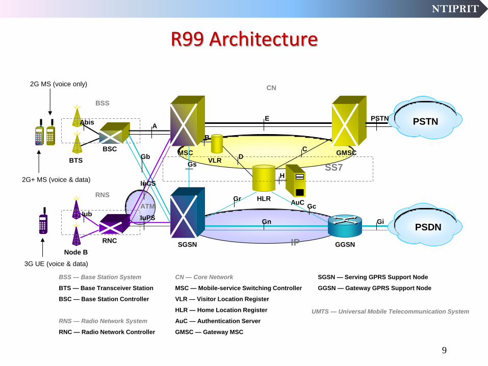
R99 Architecture
SS7
IP
BTS
BSC MSC
VLR
HLR AuC
GMSC
BSS
SGSN GGSN
PSTN
PSDN
CN
C D
Gc Gr
Gn Gi
Abis
Gs
B
H
BSS — Base Station System
BTS — Base Transceiver Station
BSC — Base Station Controller
RNS — Radio Network System
RNC — Radio Network Controller
CN — Core Network
MSC — Mobile-service Switching Controller
VLR — Visitor Location Register
HLR — Home Location Register
AuC — Authentication Server
GMSC — Gateway MSC
SGSN — Serving GPRS Support Node
GGSN — Gateway GPRS Support Node
A E PSTN
2G MS (voice only)
2G+ MS (voice & data)
UMTS — Universal Mobile Telecommunication System
Gb
3G UE (voice & data)
Node B
RNC
RNS
Iub
IuCS
ATM
IuPS
NTIPRIT
10
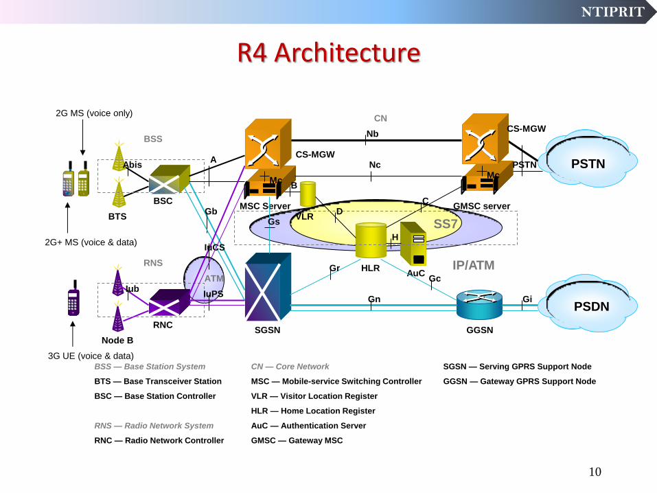
R4 Architecture
SS7
IP/ATM
BTS
BSC MSC Server
VLR
HLR AuC
GMSC server
BSS
SGSN GGSN
PSTN
PSDN
CN
C D
Gc Gr
Gn Gi
Gb
Abis
Gs
B
H
BSS — Base Station System
BTS — Base Transceiver Station
BSC — Base Station Controller
RNS — Radio Network System
RNC — Radio Network Controller
CN — Core Network
MSC — Mobile-service Switching Controller
VLR — Visitor Location Register
HLR — Home Location Register
AuC — Authentication Server
GMSC — Gateway MSC
SGSN — Serving GPRS Support Node
GGSN — Gateway GPRS Support Node
A Nc
2G MS (voice only)
2G+ MS (voice & data)
Node B
RNC
RNS
Iub
IuCS
IuPS
3G UE (voice & data)
Mc
CS-MGW
CS-MGW Nb
PSTN Mc
ATM

NTIPRIT
R4 Split Architecture
Application Servers
Application Service enablers
Services/applications
Control
Servers
Control
MSC HLR/AuC GMSC/Transit
Connectivity MGW MGW
Server Server
PSTN/
ISDN
Internet
Intranets GGSN SGSN
SGW
User data GSM
EDGE
WCDMA
NTIPRIT
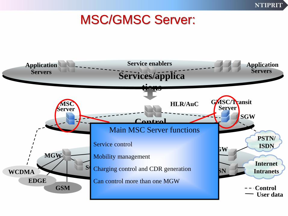
MSC/GMSC Server:
Application Servers
Application Service enablers
Services/applica
tions
Control
Servers
Control
MSC HLR/AuC GMSC/Transit
Connectivity MGW MGW
Server Server
PSTN/
ISDN
Internet
Intranets GGSN SGSN
SGW
User data
Main MSC Server functions
Service control
Mobility management
Charging control and CDR generation
Can control more than one MGW GSM
EDGE
WCDMA

NTIPRIT
Media Gateway:
Application Servers
Application Service enablers
Services/applica
tions
Servers
Control
MSC HLR/AuC/FNR GMSC/Transit
Connectivity MGW MGW
Server Server
PSTN/
ISDN
Internet
Intranets GGSN SGSN
SGW
Control User data
GSM
EDGE
WCDMA
Main Media Gateway functions
Speech & media processing
Setup/release of user data bearers
Interfacing between different transport standards
Boundary between different networks
Can be controlled by several MSC Servers

NTIPRIT
14
R5 Architecture
Gb/IuPS
A/IuCS
SS7
IP/ATM
BTS
BSC MSC Server
VLR
HSS AuC
GMSC server
BSS
SGSN GGSN
PSTN
CN
C D
Gc Gr
Gn Gi
Abis
Gs
B
H
IMS— IP Multimedia sub-system
MRF — Media Resource Function
CSCF — Call State Control Function
MGCF — Media Gateway Control Function (Mc=H248,Mg=SIP)
IM-MGW — IP Multimedia-MGW
Nc
2G MS (voice only)
2G+ MS (voice & data)
Node B
RNC
RNS
Iub
3G UE (voice & data)
Mc
CS-MGW
CS-MGW Nb
PSTN Mc
IuCS
IuPS
ATM
IMS
IP PSTN
Mc
MGCF
IM-MGW
MRF
CSCF
Mg
Gs
IP Network

NTIPRIT
15
R6 Architecture
Ww, Wu
Ut
CS-Domain
-or-
PSTN
-or-
Legacy
-or-
External
PS-Domain
CSCF
MRF-
C
CAP
Mr
Cx
Sh
Gr
Mm
Mw
Mn
Gc
Mg
Gn Iu
BGCF
Mi
Mk
Mj
Go
Gm
Dx
„Mb/Gi-Cloud“
PDF MRF-P
Mp
ISC
Uu
Operator 2
Si
IMS Terminal
UTRAN /
GERAN
Multimedia
IP
Networks
MGCF
MGW
IP Multimedia
Subsystem (IMS)
Sh BGCF
Gq
CSCF
SLF
Applications
Services
AS
OSA-SCS
IM-SSF Presence
IM
Dh
GGSN
HSS
HLR
Wx
SGSN
WLAN
Access,
WAG
AAA
PDGW WLAN
(Home) Wu, Wp
Wm

NTIPRIT
IMS
IMS is an architecture designed to support the control
layer for packet based services, which uses the bearer
services of the access network to support the media
associated with the service.
IMS is access agnostic. In a multi-access environment it
ensures service availability to all access networks.
IMS uses SIP capabilities.
16

NTIPRIT
IMS : Convergence through an overlay network
RNC
P-CSCF I-CSCF
MRF IMS
S-CSCF
MSC(Server) SGSN
GGSN
CN
MGW
BSC
GSM/GPRS/WCDMA/HSDPA
WLAN
Corporate
SIP Application
Servers SIP Application
Servers
HSS
CDMA 2000 Fixed
IMS – a cornerstone for Convergence
HLR
17

NTIPRIT
18
3GPP 3GPP Release 8
LTE
“All IP” network.
3GPP Release 9
LTE Enhancements
Increasing LTE’s suitability for different markets and deployments.
3GPP Release 10
LTE- Advanced
Carrier Aggregation

NTIPRIT
Evolution : Outcome
19

NTIPRIT
LONG TERM EVOLUTION
(LTE)
20
NTIPRIT
Key requirements for LTE
Need for higher data rates
Greater spectral efficiency
Greater flexibility of spectrum usage
Always‐on experience (reduce control plane latency)
Reduce round trip delay (transmission latency)
Need for Packet Switched optimized system
Need for high quality of services
Reasonable power consumption of mobile terminal
21

NTIPRIT
22
Key Technologies of LTE
Three fundamental technologies shaped the LTE design :
Multi carrier technology • OFDMA for Downlink • SC-FDMA for Uplink
Multiple Antenna technology
• MIMO
Packet switched radio Interface
• All IP in RF

NTIPRIT
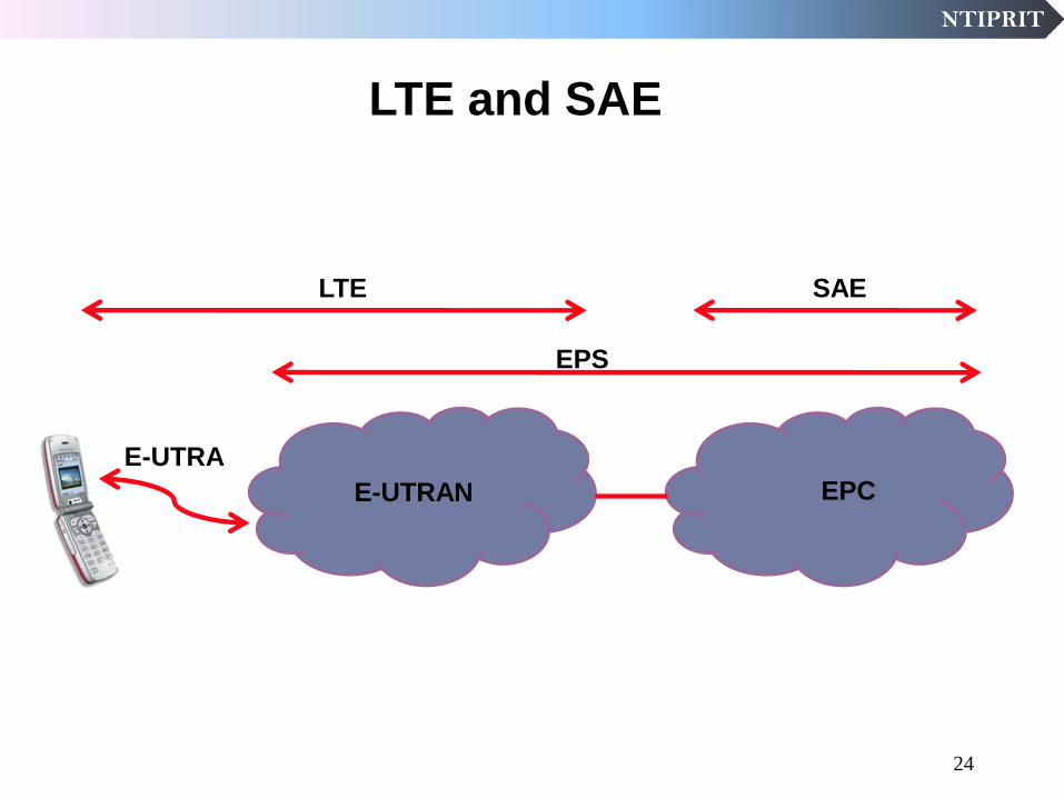
Long Term Evolution (LTE) is the term used to describe
collectively the evolution of the radio access network into
Evolved Universal Terrestrial Radio Access Network
(E-UTRAN) and the radio access technology into Evolved
Universal Terrestrial Radio Access (E-UTRA).
System Architecture Evolution (SAE) is the term used
to describe the evolution of the core network into the
Evolved Packet Core (EPC).
There is also a collective term, Evolved packet System (EPS),
which refers to the combined E-UTRAN and EPC.
LTE and SAE
23
NTIPRIT
LTE and SAE
E-UTRAN EPC
SAE LTE
EPS
E-UTRA
24

NTIPRIT
Orthogonal Frequency Division Multiple Access
(OFDMA)
25

NTIPRIT
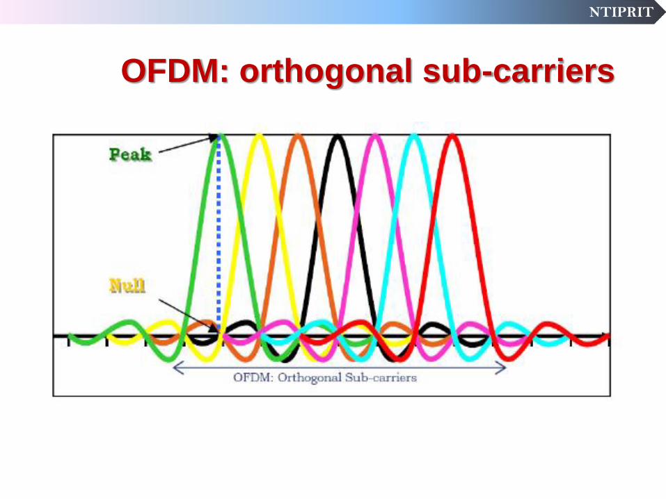
OFDM introduction
It is a Digital Multi Carrier modulation Scheme.
The Available spectrum is divided into several independent sub-carrier to carry data and control information.
The sub-carriers are selected in a manner so that they are orthogonal to one another. This prevents interference between closely spaced sub-carriers.
All orthogonal sub-carriers are transmitted simultaneously.
Orthogonality is achieved by coinciding peak of each sub carrier with null of other sub carriers.
Independent sub carriers are individually modulated and demodulated with conventional modulation formats.

NTIPRIT
27
OFDM Basic Concept
OFDM is a special case of Frequency Division Multiplexing (FDM)
For FDM • No special relationship
between the carrier frequencies
• Guard bands have to be inserted to avoid Adjacent
Channel Interference (ACI)
For OFDM
• Strict relation between carriers
• Carriers are orthogonal to each other and can be packed tight
NTIPRIT
OFDM: orthogonal sub-carriers

NTIPRIT
Downlink radio access - OFDMA
Better Coverage and Penetration
Ultra high spectral efficiency
High resistance to Multipath /ISI
Enables Multipath mitigation without using Equalizers and training sequences.
Useful for Rural, Semi urban, Urban, Dense Urban application.
Offers Frequency diversity by spreading the carriers all over the used spectrum.
OFDM
Multi-layered transmission
TX RX
29
NTIPRIT
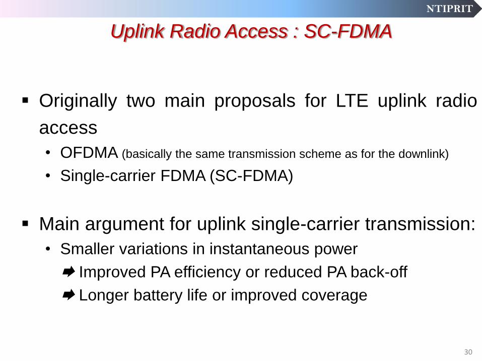
Uplink Radio Access : SC-FDMA
Originally two main proposals for LTE uplink radio
access
• OFDMA (basically the same transmission scheme as for the downlink)
• Single-carrier FDMA (SC-FDMA)
Main argument for uplink single-carrier transmission:
• Smaller variations in instantaneous power
Improved PA efficiency or reduced PA back-off
Longer battery life or improved coverage
30

NTIPRIT
Uplink radio access– Single-carrier FDMA
Single-carrier Low peak-to-average power ratio
• Improved coverage
• Higher data rates for a given coverage
• Reduced power consumption Improved battery life
Enhanced Inter-user orthogonality by means of FDMA
• No Overlap in frequency plane for each user
• No intra-cell interference
• Improved coverage and capacity
31

NTIPRIT
Multiple Input Multiple Output
(MIMO)
32

NTIPRIT
Multiple-Input Multiple Output (MIMO) has emerged as one of the
most promising approaches to achieve higher data rates in
cellular systems.
MIMO systems increase complexity with the use of multiple
antennas and associated DSP systems at both the transmitter and
the receiver but
they provide significant benefit by scaling the theoretical achievable
spectral efficiency linearly with the number of transmit and receive
antenna pairs.
OVERVIEW OF MIMO
33
NTIPRIT
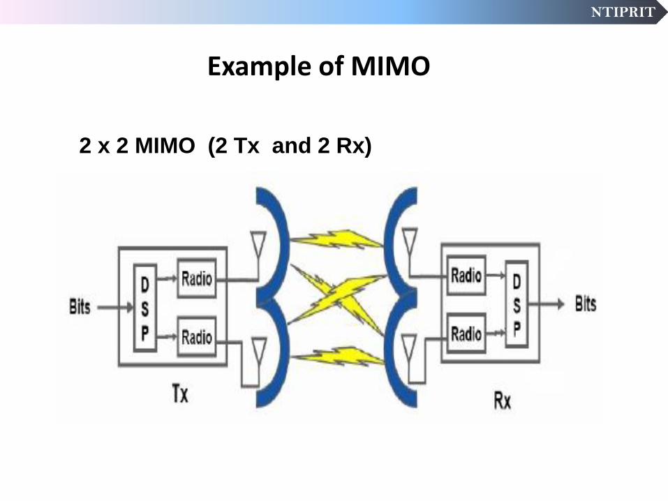
Example of MIMO
2 x 2 MIMO (2 Tx and 2 Rx)

NTIPRIT
MIMO Wireless Systems
Multiple Input Multiple Output (MIMO) systems with multiple parallel radios improve the following:
Outages reduced by using information from multiple antennas.
Transmit power can be increased via multiple power amplifiers.
Higher throughputs possible.
channel
Radio
D
S
P
Bits
TX
Radio
Radio
D
S
P
Bits
RX
Radio
35

NTIPRIT
36
MIMO : Key fundamentals
Three fundamental principles : Diversity gain
• Use of spatial diversity provided by multiple antennas improved the robustness of transmission against mutipath fading
Array gain
• Concentration of energy in one or more given directions via beamforming
Spatial Multiplexing gain
• Transmission of multiple signal streams to a single user
NTIPRIT
Multiple antennas are used , on both sides of the link.
Copies of the same signal, coded differently, are each sent
over a different transmit antenna.
Diversity gain: combats fading effects
MIMO: Diversity Gain

NTIPRIT
Enhances signal reception through directional array gain. Extends cell coverage Suppresses interference in space domain Enhances system capacity Prolongs battery life
MIMO – Beamforming
38

NTIPRIT
Spatial Multiplexing MIMO Concept
Spatial multiplexing concept:
• Form multiple independent links (on same channel) between transmitter and receiver to communicate at higher total data rates
Radio
Radio
DSP
DSP
Bit
Split Bits
Bit
Merge
TX
Radio
Radio RX
Bits
DSP
DSP

NTIPRIT
Spatial Multiplexing MIMO Reality
Radio
Radio
DSP
DSP
D
S
P
Bit
Split Bits
Bit
Merge
TX
Radio
Radio
Bits
RX
Spatial multiplexing concept:
• Form multiple independent links (on same channel) between
transmitter and receiver to communicate at higher total data rates
• However, there are cross-paths between antennas
• The correlation must be decoupled by digital signal processing
algorithms
NTIPRIT
System Architecture Evolution
(SAE)
41

NTIPRIT
LTE
42
3GPP defined LTE as an IP-based, flat network architecture.
In the User Plane (UP) of the Evolved Packet System (EPS), there
are only two types of nodes (Base Stations and Gateways) while in
current hierarchical networks there are four types (Node B, RNC,
SGSN, GGSN).
Flat architecture with less involved nodes reduces latencies and
improves performance.

NTIPRIT
LTE Network Architecture
43

NTIPRIT
LTE/SAE Network Elements
Evolved UTRAN (E-UTRAN)
HSS
S10
S6a
MME: Mobility Management Entity
PCRF:Policy & Charging Rule Function
LTE-UE
MME
S11
S1-MME PCRF
S7
Rx+ Evolved Node B
(eNB)
X2
Serving Gateway
S1-U
PDN
Gateway
PDN SGi S5/S8
cell
LTE-Uu
SAE
Gateway
Evolved Packet Core (EPC)
44

NTIPRIT
LTE-SAE Architecture
Logical network elements for the Basic System Architecture
User Equipment (UE)
E-UTRAN Node B (eNodeB)
Mobility Management Entity (MME)
Serving Gateway (S-GW)
PDN Gateway (PDN-GW)
Policy and Charging Resource Function (PCRF)
Home Subscription Server (HSS)
45

NTIPRIT
User Equipment (UE)
UE is the device that the end user applies for communication.
Typically it is a hand held device such as a smart phone or a data
card such as those used currently in 2G and 3G, or it could be
embedded, e.g. to a laptop.
UE also contains the Universal Subscriber Identity Module (USIM)
USIM is used to identify and authenticate the user and to derive
security keys for protecting the radio interface transmission.
46

NTIPRIT
E-UTRAN Node B (eNodeB)
10
• It replaces the old Node B / RNC combination from 3G. It provides all radio
management functions.
• Most of the typical protocols implemented in Radio Network Controller
(RNC) are moved to the eNodeB.
• Benefits of the RNC and Node-B merger include reduced latency with fewer
hops in the media path, and distribution of the RNC processing load
UE
X1
eNB
cell
cell
eNB
X2
47

NTIPRIT
It is a pure signalling entity inside the EPC.
Functionality of the MME is signaling coordination to setup transport
bearers through the EPC for a UE.
SAE uses tracking areas to track the position of idle UEs. The basic
principle is identical to location or routing areas from 2G/3G.
MME handles attaches and detaches to the SAE system as well as
tracking area updates .Therefore it possesses an interface towards the
HSS (home subscriber server) which stores the subscription relevant
information and the currently assigned MME in its permanent data base.
Mobility Management Entity (MME)
eNB
cell
MME HSS
SAE-GW S1-U
S1-MME
S11
S6-a
MME
S10
48

NTIPRIT
The serving gateway is a network element that manages the user data
path (SAE bearers) within EPC.
Serving gateway is some kind of distribution and packet data anchoring
function within EPC
It relays the packet data within EPC via the S5/S8 interface to or from the
PDN gateway
Lawful Interception support
eNB
cell
MME HSS
S1-U
S1-MME
S11
S6-a
PDN-GW
SAE-GW
Serving S5 / S8
Serving SAE Gateway (SAE-GW)
49

NTIPRIT
The PDN gateway provides the connection between EPC and a number
of external data networks.
It is comparable to GGSN in 2G/3G networks.
Charging support.
IP Address Allocation for UE.
Packet Routing/Forwarding between Serving GW and external Data
Network and Packet screening (firewall functionality).
PDN SAE Gateway (PDN-GW)
eNB
cell
MME HSS
S1-U
S1-MME
S11
S6-a
PDN-GW
SAE-GW
Serving S5 / S8
PCRF
PDN
S7 Rx+
SGi
50

NTIPRIT
The PCRF major functionality is the Quality of Service (QoS) coordination
between the external PDN and EPC.
PCRF is connected via Rx+ interface to the external Data network .
PCRF can be used to check and modify the QoS associated with a SAE
bearer setup from SAE or to request the setup of a SAE bearer from the
PDN.
Policy and Charging Function (PCRF)
eNB
cell
MME HSS
S1-U
S1-MME
S11
S6-a
PDN-GW
SAE-GW
Serving S5 / S8
PCRF
PDN
S7 Rx+
SGi
51
NTIPRIT
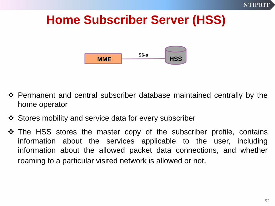
Permanent and central subscriber database maintained centrally by the
home operator
Stores mobility and service data for every subscriber
The HSS stores the master copy of the subscriber profile, contains
information about the services applicable to the user, including
information about the allowed packet data connections, and whether
roaming to a particular visited network is allowed or not.
Home Subscriber Server (HSS)
MME HSS S6-a
52

NTIPRIT
LTE Technology Solution
Implementation
53

NTIPRIT
Upgrade Path for Existing Operators
54
Radio Access Network Core Network
2G, 3G,
GSM, EVDO,
HSPA
Backhaul
Network
2G, 3G, Core
Network
All-IP Core
Network
Next Generation
Access Network
LTE or WiMAX
Conversion to all-IP core & increased
backhaul capacity required in either case
Increased
BH Capacity
T1,E1s

NTIPRIT
Long-term evolution – Spectrum flexibility
Efficient operation in differently-sized spectrum allocations
• Up to 20 MHz to enable very high data rates
• Less than 5 MHz to enable smooth spectrum migration
5 MHz < 5 MHz 10 MHz 15 MHz 20 MHz
Operation in a wide range of frequency bands
– Current and future 3G spectrum (2 GHz, 2.6 GHz, …)
– Migration of 2G spectrum
– Re-farming of other spectrum
Duplex flexibility – Both FDD and TDD mode-of-operations (i.e. operation in Paired as well as
Unpaired spectrun)
55

NTIPRIT
Long-term evolution – Duplex flexibility
Possibility for operation in paired and unpaired spectrum
Support for both FDD and TDD operation
Maximum commonality between FDD and TDD
• Strong requirement from some operators
fDL
fUL
FDD-only
Paired spectrum
Highest data rates for given
TX bandwidth and peak power
fDL
fUL
Combined FDD/TDD
Reduced UE complexity
(paired spectrum)
fDL/UL
TDD-only
Unpaired spectrum
56

NTIPRIT
Mobility Support
3GPP anchor:
- Mobility anchor between 2G/3G and LTE.
SAE anchor:
- Mobility anchor between 3GPP and non 3GPP.
MME
UPE
3GPP
Anchor
SAE
Anchor
EPC
SAE -GW

NTIPRIT
Interworking
GERAN
UTRAN
E-UTRAN Non 3GPP
IP Access
GPRS Core
Evolved Packet
Core
58

NTIPRIT
59
NTIPRIT
LTE deployments in India
Operators
Services offered
Spectrum used for 4G
TDD-LTE deployments in 2300 MHz
FDD-LTE deployments in 1800 MHz & 850 MHz
700 MHz likely to be used (under auction)
VoLTE services recently introduced
• Competition
Free voice
Data Plans
60

NTIPRIT
61
Path to 5G 3GPP Release 11
Self Optimizing Networks
Carrier Aggregation enhancements
3GPP Release 12
LTE Advance Enhancements
Heterogeneous Networks.
3GPP Release 13
5G
M2M Communications
Active Antenna Systems
LTE deployment in unlicensed spectrum

NTIPRIT
Thank You
62