
Technology Resource Document for the Assembled Chemical … · email: [email protected]....
280
ANL/EAD/TM-101 Volume 2 Technology Resource Document for the Assembled Chemical Weapons Assessment Environmental Impact Statement Volume 2: Assembled Systems for Weapons Destruction at Anniston Army Depot Environmental Assessment Division Argonne National Laboratory Operated by The University of Chicago, under Contract W-31-109-Eng-38, for the United States Department of Energy
Transcript of Technology Resource Document for the Assembled Chemical … · email: [email protected]....

ANL/EAD/TM-101Volume 2
Technology Resource Document for theAssembled Chemical Weapons AssessmentEnvironmental Impact StatementVolume 2: Assembled Systems forWeapons Destruction at Anniston Army Depot
Environmental Assessment Division
Argonne National Laboratory
Operated by The University of Chicago,under Contract W-31-109-Eng-38, for the
United States Department of Energy

Argonne National LaboratoryArgonne National Laboratory, with facilities in the states of Illinois and Idaho, isowned by the United States Government and operated by The Universityof Chicago under the provisions of a contract with the Department of Energy.
This technical memorandum is a product of Argonne’s Environmental AssessmentDivision (EAD). For information on the division's scientific and engineering activities,contact:
Director, Environmental Assessment DivisionArgonne National LaboratoryArgonne, Illinois 60439-4832Telephone (630) 252-3107
Presented in this technical memorandum are preliminary results of ongoing work orwork that is more limited in scope and depth than that described in formal reportsissued by the EAD.
Publishing support services were provided by Argonne’s Informationand Publishing Division (for more information, see IPD’s home page:http://www.ipd.anl.gov/).
DisclaimerThis report was prepared as an account of work sponsored by an agency of theUnited States Government. Neither the United States Government nor any agencythereof, nor The University of Chicago, nor any of their employees or officers,makes any warranty, express or implied, or assumes any legal liability orresponsibility for the accuracy, completeness, or usefulness of any information,apparatus, product, or process disclosed, or represents that its use would notinfringe privately owned rights. Reference herein to any specific commercialproduct, process, or service by trade name, trademark, manufacturer, or otherwisedoes not necessarily constitute or imply its endorsement, recommendation, orfavoring by the United States Government or any agency thereof. The views andopinions of document authors expressed herein do not necessarily state or reflectthose of the United States Government or any agency thereof, Argonne NationalLaboratory, or The University of Chicago.
Available electronically at http://www.doe.gov/bridgeAvailable for a processing fee to U.S. Department of Energyand its contractors, in paper, from:U.S. Department of EnergyOffice of Scientific and Technical InformationP.O. Box 62Oak Ridge, TN 37831-0062phone: (865) 576-8401fax: (865) 576-5728email: [email protected]

ANL/EAD/TM-101Volume 2
Technology Resource Document for theAssembled Chemical Weapons AssessmentEnvironmental Impact StatementVolume 2: Assembled Systems forWeapons Destruction at Anniston Army Depot
by T. Kimmell, S. Folga, G. Frey, J. Molberg, P. Kier, B. Templin, and M. Goldberg
Environmental Assessment DivisionArgonne National Laboratory, 9700 South Cass Avenue, Argonne, Illinois 60439
May 2001
Work sponsored by U.S. Department of Defense, Program Manager for Assembled Chemical WeaponsAssessment, Aberdeen Proving Ground, Maryland

This report is printed on recycled paper.

TRD Vol. 2: ANAD May 2001
iii
CONTENTS
NOTATION ............................................................................................................................. xix
2.1 INTRODUCTION........................................................................................................... 1
2.1.1 Document Purpose................................................................................................ 12.1.2 The Assembled Chemical Weapons Assessment Program
at Anniston Army Depot....................................................................................... 12.1.3 Organization of Technical Resource Document................................................... 7
2.2 ASSEMBLED SYSTEMS FOR WEAPONS DESTRUCTIONAT ANNISTON ARMY DEPOT ................................................................................... 11
2.2.1 Neutralization/SCWO........................................................................................... 122.2.1.1 Process Overview .................................................................................. 122.2.1.2 History of Destructive Processes ........................................................... 15
2.2.1.2.1 Neutralization of Agent and Energetics............................... 152.2.1.2.2 Supercritical Water Oxidation ............................................. 16
2.2.1.3 Demonstration Testing........................................................................... 172.2.1.3.1 Agent Hydrolysis ................................................................. 192.2.1.3.2 Energetics Hydrolysis .......................................................... 202.2.1.3.3 Dunnage Shredder/Hydropulper System ............................. 202.2.1.3.4 Energetics Rotary Hydrolyzer ............................................. 212.2.1.3.5 SCWO – Agent Hydrolysate ............................................... 222.2.1.3.6 SCWO – Energetics/Dunnage Hydrolysate......................... 232.2.1.3.7 Summary of Demonstration Testing.................................... 24
2.2.1.4 Engineering Design Studies................................................................... 262.2.1.4.1 Energetics Hydrolysis .......................................................... 262.2.1.4.2 Agent Hydrolysis ................................................................. 282.2.1.4.3 Energetics Rotary Hydrolyzer ............................................. 282.2.1.4.4 Dunnage Shredder/Hydropulper System ............................. 282.2.1.4.5 Solid-Wall Supercritical Water Oxidation........................... 29
2.2.1.5 Detailed Process Description................................................................. 292.2.1.5.1 Munitions Access – Projectiles and Mortars ....................... 322.2.1.5.2 Munitions Access – Rockets................................................ 332.2.1.5.3 Munitions Access – Land Mines ......................................... 332.2.1.5.4 Agent Treatment .................................................................. 342.2.1.5.5 Energetics Treatment ........................................................... 352.2.1.5.6 Metal Parts Treatment.......................................................... 362.2.1.5.7 Dunnage Treatment ............................................................. 362.2.1.5.8 Effluent Management and Pollution Controls ..................... 37
2.2.1.6 Common Elements – Other Systems ..................................................... 38

TRD Vol. 2: ANAD May 2001
iv
CONTENTS (Cont.)
2.2.2 Neutralization/Biotreatment ................................................................................. 392.2.2.1 Process Overview .................................................................................. 392.2.2.2 History of Destructive Processes ........................................................... 40
2.2.2.2.1 Neutralization of Agent and Energetics............................... 402.2.2.2.2 Biological Treatment ........................................................... 41
2.2.2.3 Demonstration Testing........................................................................... 412.2.2.3.1 Agent Hydrolysis ................................................................. 422.2.2.3.2 Energetics Hydrolysis .......................................................... 432.2.2.3.3 Rocket-Cutting and Fluid-Mining ....................................... 432.2.2.3.4 Immobilized Cell Bioreactor and Catalytic
Oxidation ............................................................................. 452.2.2.3.5 Metal Parts Treater and Catalytic Oxidation ....................... 462.2.2.3.6 Summary of Demonstration Testing.................................... 48
2.2.2.4 Engineering Design Studies................................................................... 492.2.2.4.1 Energetics Hydrolysis .......................................................... 502.2.2.4.2 Agent Hydrolysis ................................................................. 512.2.2.4.3 Immobilized Cell Bioreactor and Catalytic
Oxidation ............................................................................. 512.2.2.4.4 Continuous Steam Treater and Catalytic
Oxidation ............................................................................. 522.2.2.4.5 Catalytic Oxidation Unit...................................................... 52
2.2.2.5 Detailed Process Description................................................................. 532.2.2.5.1 Munitions Access – Projectiles and Mortars ....................... 552.2.2.5.2 Munitions Access – Rockets................................................ 562.2.2.5.3 Agent Treatment .................................................................. 572.2.2.5.4 Energetics Treatment ........................................................... 572.2.2.5.5 Metal Parts Treatment.......................................................... 582.2.2.5.6 Dunnage Treatment ............................................................. 582.2.2.5.7 Effluent Management and Pollution Controls ..................... 58
2.2.2.6 Common Elements – Other Systems ..................................................... 592.2.3 Neutralization/GPCR/TW-SCWO........................................................................ 60
2.2.3.1 Process Overview .................................................................................. 602.2.3.2 History of Destructive Processes ........................................................... 63
2.2.3.2.1 Neutralization of Agent and Energetics............................... 632.2.3.2.2 Gas-Phase Chemical Reduction........................................... 632.2.3.2.3 Transpiring-Wall Supercritical Water Oxidation ................ 64
2.2.3.3 Demonstration Testing........................................................................... 652.2.3.3.1 Agent Hydrolysis ................................................................. 662.2.3.3.2 Energetics Hydrolysis .......................................................... 672.2.3.3.3 TW-SCWO Energetics/Agent Hydrolysate ......................... 672.2.3.3.4 Gas-Phase Chemical Reduction Reactor ............................. 702.2.3.3.5 Summary of Demonstration Testing.................................... 72
2.2.3.4 Engineering Design Studies................................................................... 73

TRD Vol. 2: ANAD May 2001
v
CONTENTS (Cont.)
2.2.3.4.1 Energetics Hydrolysis .......................................................... 732.2.3.4.2 Agent Hydrolysis ................................................................. 732.2.3.4.3 Munitions Access................................................................. 742.2.3.4.4 TW-SCWO .......................................................................... 742.2.3.4.5 GPCR................................................................................... 75
2.2.3.5 Detailed Process Description................................................................. 752.2.3.5.1 Munitions Access – Projectiles and Mortars ....................... 782.2.3.5.2 Munitions Access – Rockets................................................ 792.2.3.5.3 Agent Treatment .................................................................. 802.2.3.5.4 Energetics Treatment ........................................................... 812.2.3.5.5 Metal Parts and Dunnage Treatment and Process
Off-Gas Treatment............................................................... 812.2.3.5.6 Effluent Management and Pollution Controls ..................... 83
2.2.3.6 Common Elements S Other Systems ..................................................... 842.2.4 Electrochemical Oxidation ................................................................................... 85
2.2.4.1 Process Overview .................................................................................. 852.2.4.2 History of Destructive Processes ........................................................... 872.2.4.3 Demonstration Testing........................................................................... 88
2.2.4.3.1 2-kW SILVER II Unit ......................................................... 902.2.4.3.2 12-kW SILVER II Unit ....................................................... 922.2.4.3.3 Summary of Demonstration Testing.................................... 94
2.2.4.4 Engineering Design Studies................................................................... 952.2.4.5 Detailed Process Description................................................................. 97
2.2.4.5.1 Munitions Access – General ................................................ 992.2.4.5.2 Munitions Access – Projectiles and Mortars ....................... 1002.2.4.5.3 Munitions Access – M55 Rockets ....................................... 1002.2.4.5.4 Munitions Access – Land Mines ......................................... 1012.2.4.5.5 Agent and Energetics Treatment.......................................... 1022.2.4.5.6 Metals Parts Treatment ........................................................ 1062.2.4.5.7 Dunnage Treatment ............................................................. 1072.2.4.5.8 Effluent Management and Pollution Controls ..................... 107
2.2.4.6 Common Elements – Other Systems ..................................................... 1082.2.5 Combination Treatment Technologies.................................................................. 109
2.3 SUPPLEMENTAL INFORMATION FOR ASSEMBLED SYSTEMSAT ANNISTON ARMY DEPOT ................................................................................... 111
2.3.1 General Facility Location and Footprint............................................................... 1112.3.2 Neutralization/SCWO........................................................................................... 114
2.3.2.1 General Facility Description.................................................................. 1152.3.2.2 Construction Phase ................................................................................ 116

TRD Vol. 2: ANAD May 2001
vi
CONTENTS (Cont.)
2.3.2.2.1 Construction Inputs and Resource Requirements................ 1172.3.2.2.2 Construction Workforce ...................................................... 1192.3.2.2.3 Construction Emissions and Waste Estimates..................... 121
2.3.2.3 Operations Phase ................................................................................... 1242.3.2.3.1 Preoperational Testing ......................................................... 1242.3.2.3.2 Operations Inputs and Resource Requirements ................... 1242.3.2.3.3 Operations Workforce ......................................................... 1292.3.2.3.4 Operations Emissions and Waste Estimates ........................ 130
2.3.2.4 Activities ............................................................................................. 1402.3.2.5 Uncertainties .......................................................................................... 141
2.3.3 Neutralization/Biotreatment ................................................................................. 1442.3.3.1 General Facility Description.................................................................. 1442.3.3.2 Construction Phase ................................................................................ 146
2.3.3.2.1 Construction Inputs and Resource Requirements................ 1472.3.3.2.2 Construction Workforce ...................................................... 1502.3.3.2.3 Construction Emissions and Waste Estimates..................... 151
2.3.3.3 Operations Phase ................................................................................... 1522.3.3.3.1 Preoperational Testing ......................................................... 1532.3.3.3.2 Operations Inputs and Resource Requirements ................... 1532.3.3.3.3 Operations Workforce ......................................................... 1542.3.3.3.4 Operations Emissions and Waste Estimates ........................ 154
2.3.3.4 Activities ............................................................................................. 1702.3.3.5 Uncertainties .......................................................................................... 170
2.3.4 Neutralization/GPCR/TW-SCWO........................................................................ 1732.3.4.1 General Facility Description.................................................................. 1742.3.4.2 Construction Phase ................................................................................ 175
2.3.4.2.1 Construction Inputs and Resource Requirements................ 1762.3.4.2.2 Construction Workforce ...................................................... 1782.3.4.2.3 Construction Emissions and Waste Estimates..................... 179
2.3.4.3 Operations Phase ................................................................................... 1832.3.4.3.1 Preoperational Testing ......................................................... 1832.3.4.3.2 Operations Inputs and Resource Requirements ................... 1842.3.4.3.3 Operations Workforce ......................................................... 1892.3.4.3.4 Operations Emissions and Waste Estimates ........................ 190
2.3.4.4 Activities ............................................................................................. 2052.3.4.5 Uncertainties .......................................................................................... 205
2.3.5 Electrochemical Oxidation ................................................................................... 2062.3.5.1 General Facility Description.................................................................. 2102.3.5.2 Construction Phase ................................................................................ 210
2.3.5.2.1 Construction Inputs and Resource Requirements................ 2102.3.5.2.1 Construction Workforce ...................................................... 2122.3.5.2.2 Construction Emissions and Waste Estimates..................... 213

TRD Vol. 2: ANAD May 2001
vii
CONTENTS (Cont.)
2.3.5.3 Operations Phase ................................................................................... 2172.3.5.3.1 Preoperational Testing ......................................................... 2172.3.5.3.2 Operations Inputs and Resource Requirements ................... 2212.3.5.3.3 Operations Workforce ......................................................... 2232.3.5.3.4 Operations Emissions and Waste Estimates ........................ 224
2.3.5.4 Activities ............................................................................................. 2332.3.5.5 Uncertainties .......................................................................................... 234
2.3.6 Dismantling and Closure ...................................................................................... 2392.3.7 Combination Treatment Technologies.................................................................. 247
2.4 REFERENCES................................................................................................................ 249
FIGURES
2.1 Types of Agent, Quantities of Agent, Types of Munitions, and Percentageof Total Agent Stockpiled at Each Storage Site........................................................... 3
2.2 Organization of Technical Resource Document .......................................................... 7
2.3 Overview of the Neutralization/SCWO Process for the Treatment ofACW at ANAD ............................................................................................................ 14
2.4 Typical Flow Diagram for SCWO ............................................................................... 17
2.5 Flow Diagram of Neutralization/SCWO Showing Units or OperationsUndergoing Engineering Design — Projectiles and Mortars....................................... 27
2.6 Flow Diagram of Neutralization/SCWO Showing Units or OperationsUndergoing Engineering Design — M55 Rockets and Land Mines ........................... 27
2.7 Flow Diagram of Entire Neutralization Solid-Wall SCWO Processat ANAD ...................................................................................................................... 30
2.8 Overview of the Neutralization/Biotreatment Process for the Treatmentof ACW at ANAD........................................................................................................ 40
2.9 Flow Diagram of Neutralization/Biotreatment Showing Units or OperationsUndergoing Engineering Design — Projectiles and Mortars....................................... 50
2.10 Flow Diagram of Entire Neutralization/Biotreatment Process at ANAD.................... 54

TRD Vol. 2: ANAD May 2001
viii
FIGURES (Cont.)
2.11 Overview of the Neutralization/GPCR/TW-SCWO Process for theTreatment of ACW at ANAD ...................................................................................... 61
2.12 Neutralization/GPCR/TW-SCWO Process Overview Showing DifferentAreas of the Destruction Facility ................................................................................. 62
2.13 Flow Diagram of Gas-Phase Chemical Reduction....................................................... 63
2.14 Transpiring Wall-SCWO Reactor ................................................................................ 65
2.15 Flow Diagram of Neutralization/GPCR/TW-SCWO Process ShowingUnits or Operations Undergoing Engineering Design ................................................. 75
2.16 Flow Diagram of Entire Neutralization/GPCR/TW-SCWO Processat ANAD ...................................................................................................................... 77
2.17 Overview of the AEA/CH2MHILL SILVER II Treatment Process ............................ 86
2.18 Flow Diagram of Electrochemical Oxidation SILVER II ProcessShowing Units or Operations Undergoing Engineering Design .................................. 97
2.19 Flow Diagram of Electrochemical Oxidation Using the SILVER IIProcess at ANAD ......................................................................................................... 98
2.20 Process Flow Diagram for a SILVER II 2-kW Agent Plant Used inDemonstration Testing ................................................................................................. 103
2.21 Process Flow Diagram for a SILVER II 12-kW Energetics Plant Used inDemonstration Testing ................................................................................................. 103
2.22 2-kW Anode/Cathode Arrangement Used in Demonstration Testing ......................... 104
2.23 12-kW Anode/Cathode Arrangement Used in Demonstration Testing ....................... 105
2.24 Map Showing Three Potential Locations for the DemilitarizationFacility at ANAD ......................................................................................................... 112
2.25 Input/Output Material Balance for Neutralization/SCWO of ACWContaining Mustard Agent at ANAD........................................................................... 115
2.26 Input/Output Material Balance for Neutralization/SCWO of ACWContaining Nerve Agent at ANAD .............................................................................. 116
2.27 Neutralization/SCWO Facility Arrangement at ANAD............................................... 117

TRD Vol. 2: ANAD May 2001
ix
FIGURES (Cont.)
2.28 Layout of First Floor of the Munitions Demilitarization Buildingfor the Neutralization/SCWO Facility at ANAD ......................................................... 118
2.29 Layout of Second Floor of the Munitions Demilitarization Buildingfor the Neutralization/SCWO Facility at ANAD ......................................................... 119
2.30 Input/Output Material Balance for Neutralization/Biotreatment ofACW Containing Mustard Agent at ANAD ................................................................ 145
2.31 Layout of First Floor of Neutralization/Biotreatment Facility at ANAD .................... 146
2.32 Layout of Second Floor of Neutralization/Biotreatment Facility at ANAD................ 147
2.33 Layout of the Biotreatment Operation of the Neutralization/BiotreatmentFacility at ANAD ......................................................................................................... 148
2.34 Input/Output Material Balance for Neutralization/GPCR/TW-SCWOof ACW Containing Mustard Agent at ANAD............................................................ 174
2.35 Input/Output Material Balance for Neutralization/GPCR/TW-SCWOof ACW Containing GB Agent at ANAD.................................................................... 175
2.36 Input/Output Material Balance for Neutralization/GPCR/TW-SCWOof ACW Containing VX Agent at ANAD ................................................................... 176
2.37 Neutralization/GPCR/TW-SCWO Facility Layout at ANAD ..................................... 177
2.38 Layout of First Floor of the Munitions Demilitarization Buildingfor the Neutralization/GPCR/TW-SCWO Facility at ANAD...................................... 178
2.39 Layout of Second Floor of the Munitions Demilitarization Buildingfor the Neutralization/GPCR/TW-SCWO Facility at ANAD...................................... 179
2.40 Input/Output Material Balance for Electrochemical Oxidation of ACWContaining Mustard Agent at ANAD........................................................................... 211
2.41 Input/Output Material Balance for Electrochemical Oxidation of ACWContaining GB Agent at ANAD .................................................................................. 212
2.42 Input/Output Material Balance for Electrochemical Oxidation of ACWContaining VX Agent at ANAD .................................................................................. 213
2.43 Electrochemical Oxidation Facility Layout at ANAD................................................. 214

TRD Vol. 2: ANAD May 2001
x
FIGURES (Cont.)
2.44 Layout of First Floor of the Munitions Demilitarization Buildingfor the Electrochemical Oxidation Facility at ANAD.................................................. 215
2.45 Layout of Second Floor of Munitions Demilitarization Buildingfor the Electrochemical Oxidation Facility at ANAD.................................................. 216
TABLES
2.1 Chemical Munitions Inventory by Stockpile Location ................................................ 4
2.2 Chemical Munitions Inventory at ANAD .................................................................... 8
2.3 Technology Overview for Baseline Incineration and ACWA TechnologySystems for ANAD ...................................................................................................... 13
2.4 Potential Further Studies under Engineering Design Study-II..................................... 96
2.5 Approximate Distances from Potential Demilitarization FacilityLocations A, B, and C to ANAD Installation Boundaries ........................................... 113
2.6 Land Area Requirements during Technology Systems Operations ............................. 113
2.7 Estimated Materials/Resources Consumed during Construction ofa Neutralization/SCWO Facility at ANAD.................................................................. 120
2.8 Comparison of Estimated Materials/Resources with Values fora Typical Chemical Demilitarization Incineration Facility.......................................... 120
2.9 Order-of-Magnitude Estimate of the Number of Truck Shipmentsof Construction Materials for a Neutralization/SCWO Facility at ANAD .................. 121
2.10 Estimated Emissions from Delivery Vehicles during Constructionof a Neutralization/SCWO Facility at ANAD.............................................................. 122
2.11 Estimated Number of Employees Needed by Year for Construction of aNeutralization/SCWO Facility at ANAD..................................................................... 122
2.12 Estimated Criteria Pollutant Emissions during Constructionof a Neutralization/SCWO Facility at ANAD.............................................................. 123
2.13 Estimated Criteria Pollutant Emissions from Worker Commuter Vehiclesduring Construction of a Neutralization/SCWO Facility at ANAD ............................ 124

TRD Vol. 2: ANAD May 2001
xi
TABLES
2.14 Estimated Total Wastes Generated during Construction of aNeutralization/SCWO Facility at ANAD..................................................................... 125
2.15 Inventory and Estimated Processing Time for Neutralization/SCWOof ACW Containing Mustard and Nerve Agent Stored at ANAD............................... 126
2.16 Estimated Utilities Consumed during Destruction of ACW atthe Neutralization/SCWO Facility at ANAD............................................................... 126
2.17 Estimated Raw Materials Consumed Annually during NormalNeutralization/SCWO of ACW Containing Mustard Agent at ANAD ....................... 127
2.18 Estimated Raw Materials Consumed Annually during NormalNeutralization/SCWO of ACW Containing Nerve Agent at ANAD........................... 127
2.19 Transportation Data for Raw Materials for Neutralization/SCWO of ACWContaining Mustard Agent at ANAD........................................................................... 128
2.20 Transportation Data for Raw Materials for Neutralization/SCWOof ACW Containing Nerve Agent at ANAD ............................................................... 129
2.21 Stack Parameters for Neutralization/SCWO at ANAD................................................ 131
2.22 Estimated Hourly and Annual Emission Rates of Criteria Pollutantsduring Normal Neutralization/SCWO Operations at ANAD....................................... 132
2.23 Estimated Hourly and Annual TAP Emission Rates during Normal BoilerOperations for Neutralization/SCWO at ANAD.......................................................... 133
2.24 Estimated Hourly and Annual TAP Emission Rates during Emergency DieselGenerator Operations for Neutralization/SCWO at ANAD......................................... 134
2.25 Estimated Maximum Hourly and Annual Agent Emission Rates from theFilter Farm Stack during Neutralization/SCWO of ACW at ANAD........................... 135
2.26 Estimated TAP Emission Rates from the Filter Farm Stack duringNeutralization/SCWO of ACW Containing Mustard Agent at ANAD ....................... 135
2.27 Estimated TAP Emission Rates from the Filter Farm Stack duringNeutralization/SCWO of ACW Containing Nerve Agent at ANAD........................... 136
2.28 Estimated Emissions from Worker Commuter Vehicles duringNeutralization/SCWO at ANAD.................................................................................. 136

TRD Vol. 2: ANAD May 2001
xii
TABLES (Cont.)
2.29 Estimated Generation Rates of Brine Salts from Neutralization/SCWOat ANAD to Be Sent Off-Site for Land Disposal......................................................... 138
2.30 Estimated Generation Rates of 5X Solids from Neutralization/SCWOat ANAD to Be Sent Off-Site for Land Disposal or Recycling ................................... 139
2.31 Estimated Generation Rates of Other Solid Wastes from Neutralization/SCWOat ANAD To Be Sent Off-Site for Land Disposal or Recycling.................................. 139
2.32 Calculated Quantities of Solid Residues from Nonprocess Wastes fromNeutralization/SCWO of ACW Containing Mustard Agent at ANAD ....................... 139
2.33 Calculated Quantities of Solid Residues from Nonprocess Wastesfrom Neutralization/SCWO of ACW Containing Nerve Agent at ANAD .................. 140
2.34 Estimated Quantities of Other Solid Wastes at ANAD To Be Sent Off-Sitefor Land Disposal or Recycling ................................................................................... 140
2.35 Transportation Data for Solid Wastes from Neutralization/SCWOof ACW Containing Mustard Agent at ANAD............................................................ 141
2.36 Transportation Data for Solid Wastes from Neutralization/SCWOof ACW Containing Nerve Agent at ANAD ............................................................... 142
2.37 Estimated Annual Nonhazardous Waste Generated during Neutralization/SCWO Operations at ANAD ....................................................................................... 143
2.38 Activities for Neutralization/SCWO at ANAD............................................................ 143
2.39 Estimated Materials/Resources Consumed during Construction ofa Neutralization/Biotreatment Facility at ANAD......................................................... 149
2.40 Comparison of Estimated Materials/Resources with Valuesfor a Typical Chemical Demilitarization Incineration Facility .................................... 149
2.41 Order-of-Magnitude Estimate of the Number of Truck Shipments ofConstruction Materials for a Neutralization/Biotreatment Facility at ANAD ............. 150
2.42 Estimated Emissions from Delivery Vehicles for Construction of aNeutralization/Biotreatment Facility at ANAD ........................................................... 151
2.43 Estimated Number of Employees Needed by Year for Construction of aNeutralization/Biotreatment Facility at ANAD ........................................................... 151

TRD Vol. 2: ANAD May 2001
xiii
TABLES (Cont.)
2.44 Estimated Criteria Pollutant Emissions during Construction of a Neutralization/Biotreatment Facility at ANAD ................................................................................... 152
2.45 Estimated Criteria Pollutant Emissions from Worker Commuter Vehiclesduring Construction of a Neutralization/Biotreatment Facility at ANAD ................... 153
2.46 Estimated Total Wastes Generated during Construction ofa Neutralization/Biotreatment Facility at ANAD......................................................... 154
2.47 Inventory and Estimated Processing Time for Neutralization/Biotreatmentof ACW Containing Mustard Agent Stored at ANAD ................................................ 155
2.48 Estimated Utilities Consumed during Destruction of ACW atthe Neutralization/Biotreatment Facility at ANAD ..................................................... 155
2.49 Estimated Raw Materials Consumed Annually during NormalNeutralization/Biotreatment Operations at ANAD...................................................... 156
2.50 Transportation Data for Raw Materials for Neutralization/Biotreatmentof ACW Containing Mustard Agent at ANAD............................................................ 157
2.51 Stack Parameters for Neutralization/Biotreatment at ANAD ...................................... 159
2.52 Estimated Hourly and Annual Emission Rates of Criteria Pollutants duringNormal Neutralization/Biotreatment Operations at ANAD......................................... 160
2.53 Estimated Hourly and Annual TAP Emission Rates during Normal BoilerOperations for Neutralization/Biotreatment at ANAD ................................................ 161
2.54 Estimated Hourly and Annual TAP Emission Rates during Emergency DieselGenerator Operations for Neutralization/Biotreatment at ANAD ............................... 162
2.55 Estimated Maximum Hourly and Annual Agent Emission Rates from theFilter Farm Stack during Neutralization/Biotreatment at ANAD ................................ 163
2.56 Estimated TAP Emission Rates from the Biotreatment VentStack during Neutralization/Biotreatment at ANAD ................................................... 164
2.57 Estimated TAP Emission Rates from the Filter Farm Stackduring Neutralization/Biotreatment at ANAD ............................................................. 165
2.58 Estimated Emissions from Worker Commuter Vehicles duringNeutralization/Biotreatment at ANAD......................................................................... 166

TRD Vol. 2: ANAD May 2001
xiv
TABLES (Cont.)
2.59 Estimated Generation Rates of Biomass from Neutralization/Biotreatmentat ANAD To Be Sent Off-Site for Land Disposal or Recycling.................................. 167
2.60 Estimated Generation Rates of Brine Salts from Neutralization/Biotreatmentat ANAD To Be Sent Off-Site for Land Disposal or Recycling.................................. 168
2.61 Estimated Generation Rates of Scrubber Sludge from Neutralization/Biotreatment at ANAD To Be Sent Off-Site for Land Disposal or Recycling ............ 169
2.62 Estimated Generation Rates of 5X Solids from Neutralization/Biotreatment atANAD To Be Sent Off-Site for Land Disposal or Recycling...................................... 169
2.63 Calculated Quantities of Solid Residues from Nonprocess Wastes fromNeutralization/Biotreatment of ACW Containing Mustard Agent at ANAD.............. 170
2.64 Transportation Data for Solid Wastes from Neutralization/Biotreatment of ACWContaining Mustard Agent at ANAD........................................................................... 171
2.65 Estimated Annual Nonhazardous Waste Generated during Neutralization/Biotreatment Operations at ANAD.............................................................................. 172
2.66 Activities for Neutralization/Biotreatment at ANAD .................................................. 172
2.67 Estimated Materials/Resources Consumed during Construction of aNeutralization/GPCR/TW-SCWO Facility at ANAD.................................................. 180
2.68 Order-of-Magnitude Estimate of the Number of Truck Shipmentsof Construction Materials for Construction of a Neutralization/GPCR/TW-SCWO Facility at ANAD ..................................................................................... 181
2.69 Estimated Emissions from Delivery Vehicles during Construction of aNeutralization/GPCR/TW-SCWO Facility at ANAD.................................................. 182
2.70 Estimated Number of Employees Needed by Year for Construction of aNeutralization/GPCR/TW-SCWO Facility at ANAD.................................................. 182
2.71 Estimated Emissions during Construction of a Neutralization/GPCR/TW-SCWO Facility at ANAD.......................................................................... 182
2.72 Estimated Emissions from Worker Commuter Vehicles during Constructionof a Neutralization/GPCR/TW-SCWO Facility at ANAD .......................................... 183

TRD Vol. 2: ANAD May 2001
xv
TABLES (Cont.)
2.73 Estimated Total Wastes Generated during Construction of a Neutralization/GPCR/TW-SCWO Facility at ANAD.......................................................................... 184
2.74 Inventory and Estimated Processing Time for Neutralization/GPCR/TW-SCWOof ACW Containing Mustard and Nerve Agent Stored at BGAD ............................... 185
2.75 Estimated Utilities Consumed during Destruction of ACW at theNeutralization/GPCR/TW-SCWO Facility at ANAD.................................................. 186
2.76 Estimated Raw Materials Consumed Annually during NormalNeutralization/GPCR/TW/SCWO Operations at ANAD ............................................ 186
2.77 Transportation Data for Raw Materials for Neutralization/GPCR/TW-SCWOof ACW Containing Mustard Agent at ANAD............................................................ 187
2.78 Transportation Data for Raw Materials for Neutralization/GPCR/TW-SCWOof ACW Containing GB Agent at ANAD.................................................................... 188
2.79 Transportation Data for Raw Materials for Neutralization/GPCR/TW-SCWOof ACW Containing VX Agent at ANAD ................................................................... 189
2.80 Stack Parameters for Neutralization/GPCR/TW-SCWO at ANAD ............................ 191
2.81 Estimated Hourly and Annual Emission Rates of Criteria Pollutantsduring Normal Neutralization/GPCR/TW-SCWO Operations at ANAD.................... 192
2.82 Estimated Hourly and Annual TAP Emission Rates during Normal BoilerOperations for Neutralization/GPCR/TW-SCWO at ANAD....................................... 193
2.83 Estimated Hourly and Annual TAP Emission Rates during Emergency DieselGenerator Operations for Neutralization/GPCR/TW-SCWO at ANAD...................... 194
2.84 Estimated Maximum Hourly and Annual Agent Emission Rates fromthe Filter Farm Stack during Neutralization/GPCR/TW-SCWO at ANAD ................ 195
2.85 Estimated TAP Emission Rates from the Filter Farm Stack duringNeutralization/GPCR/TW-SCWO of ACW Containing GB Agent at ANAD............ 196
2.86 Estimated TAP Emission Rates from the Filter Farm Stack duringNeutralization/GPCR/TW-SCWO of ACW Containing VX Agent at ANAD............ 197
2.87 Estimated TAP Emission Rates from the Filter Farm Stack duringNeutralization/GPCR/TW-SCWO of ACW Containing MustardAgent at ANAD............................................................................................................ 198

TRD Vol. 2: ANAD May 2001
xvi
TABLES (Cont.)
2.88 Estimated TAP Emission Rates from the Product Gas Burner Stack duringNeutralization/GPCR/TW-SCWO of ACW Containing GB Agent at ANAD............ 199
2.89 Estimated TAP Emission Rates from the Product Gas Burner Stack duringNeutralization/GPCR/TW-SCWO of ACW Containing VX Agent at ANAD............ 200
2.90 Estimated TAP Emission Rates from the Product Gas Burner Stack during Neutralization/GPCR/TW-SCWO of ACW Containing Mustard Agent at ANAD ... 201
2.91 Estimated Emissions from Worker Commuter Vehicles duringNeutralization/GPCR/TW-SCWO at ANAD............................................................... 202
2.92 Estimated Generation Rates of SCWO Brine Salts from Neutralization/GPCR/TW-SCWO at ANAD To Be Sent Off-Site for Land Disposal or Recycling.............. 203
2.93 Estimated Generation Rates of TRBP Residues from Neutralization/GPCR/TW-SCWO at ANAD To Be Sent Off-Site for Land Disposal or Recycling.............. 204
2.94 Estimated Generation Rates of 5X Solids from Neutralization/GPCR/TW-SCWOat ANAD To Be Sent Off-Site for Land Disposal or Recycling.................................. 205
2.95 Transportation Data for Solid Wastes from Neutralization/GPCR/TW-SCWOof ACW Containing Mustard Agent at ANAD............................................................ 206
2.96 Transportation Data for Solid Wastes from Neutralization/GPCR/TW-SCWOof ACW Containing GB Agent at ANAD.................................................................... 207
2.97 Transportation Data for Solid Wastes from Neutralization/GPCR/TW-SCWOof ACW Containing VX Agent at ANAD ................................................................... 208
2.98 Activities for Neutralization/GPCR/TW-SCWO at ANAD......................................... 209
2.99 Estimated Materials/Resources Consumed during Construction ofan Electrochemical Oxidation Facility at ANAD ........................................................ 217
2.100 Order-of-Magnitude Estimate of the Number of Truck Shipments of ConstructionMaterials for an Electrochemical Oxidation Facility at ANAD................................... 218
2.101 Estimated Emissions from Delivery Vehicles during Construction of anElectrochemical Oxidation Facility at ANAD ............................................................. 219
2.102 Estimated Number of Construction Employees Needed by Year for Constructionof an Electrochemical Oxidation Facility at ANAD .................................................... 219

TRD Vol. 2: ANAD May 2001
xvii
TABLES (Cont.)
2.103 Estimated Emissions during Construction of an Electrochemical OxidationFacility at ANAD ......................................................................................................... 219
2.104 Estimated Emissions from Worker Commuter Vehicles during Constructionof an Electrochemical Oxidation Facility at ANAD .................................................... 220
2.105 Estimated Total Wastes Generated during Construction of anElectrochemical Oxidation Facility at ANAD ............................................................. 220
2.106 Inventory and Estimated Processing Time for Electrochemical Oxidationof the ACW Stored at ANAD ...................................................................................... 221
2.107 Estimated Utilities Consumed during Destruction of ACW at theElectrochemical Oxidation Facility at ANAD ............................................................. 222
2.108 Estimated Raw Materials Consumed Annually during NormalElectrochemical Oxidation Operations at ANAD........................................................ 223
2.109 Transportation Data for Raw Materials for Electrochemical Oxidation ofACW Containing Mustard Agent at ANAD ................................................................ 224
2.110 Transportation Data for Raw Materials for Electrochemical Oxidation ofACW Containing GB Agent at ANAD........................................................................ 225
2.111 Transportation Data for Raw Materials for Electrochemical Oxidation ofACW Containing VX Agent at ANAD........................................................................ 226
2.112 Stack Parameters for Electrochemical Oxidation at ANAD ........................................ 227
2.113 Estimated Hourly and Annual Criteria Pollutant Emission Rates duringNormal Operations of an Electrochemical Oxidation Facility at ANAD .................... 229
2.114 Estimated Hourly and Annual TAP Emission Rates during Normal BoilerOperations for Electrochemical Oxidation at ANAD .................................................. 230
2.115 Estimated Hourly and Annual TAP Emission Rates during Emergency DieselGenerator Operations for Electrochemical Oxidation at ANAD ................................. 231
2.116 Estimated Maximum Hourly and Annual Agent Emission Rates fromthe Filter Farm Stack during Electrochemical Oxidation Operations at ANAD.......... 232
2.117 Estimated TAP Emission Rates from the Filter Farm Stack duringElectrochemical Oxidation of ACW Containing GB Agent at ANAD........................ 233

TRD Vol. 2: ANAD May 2001
xviii
TABLES (Cont.)
2.118 Estimated TAP Emission Rates from the Filter Farm Stack duringElectrochemical Oxidation of ACW Containing VX Agent at ANAD ....................... 234
2.119 Estimated TAP Emission Rates from the Filter Farm Stack duringElectrochemical Oxidation of ACW Containing Mustard Agent at ANAD................ 235
2.120 Estimated Emissions from Worker Commuter Vehicles during ElectrochemicalOxidation at ANAD ..................................................................................................... 235
2.121 Estimated Generation Rates of Solid Caustic Scrubber Waste fromElectrochemical Oxidation at ANAD To Be Sent Off-Site for Land Disposalor Recycling ................................................................................................................. 236
2.122 Estimated Generation Rates of Solid Spent Anolyte-Catholyte Waste fromAgent Treatment during Electrochemical Oxidation at ANAD To Be SentOff-Site for Land Disposal or Recycling ..................................................................... 238
2.123 Estimated Generation Rates of Solid Spent Anolyte-Catholyte Waste fromEnergetics Treatment during Electrochemical Oxidation at ANAD To BeSent Off-Site for Land Disposal or Recycling ............................................................. 240
2.124 Estimated Generation Rates of 5X Solids from Agent Treatment duringElectrochemical Oxidation at ANAD To Be Sent Off-Site forLand Disposal or Recycling ......................................................................................... 241
2.125 Estimated Generation Rates of Liquid Neutralized HNO3 fromElectrochemical Oxidation at ANAD To Be Sent Off-Site forDisposal or Treatment .................................................................................................. 242
2.126 Transportation Data for Solid and Liquid Wastes from ElectrochemicalOxidation of ACW Containing Mustard Agent at ANAD........................................... 243
2.127 Transportation Data for Solid and Liquid Wastes from ElectrochemicalOxidation of ACW Containing GB Agent at ANAD................................................... 244
2.128 Transportation Data for Solid and Liquid Wastes from ElectrochemicalOxidation of ACW Containing VX Agent at ANAD .................................................. 245
2.129 Activities for Electrochemical Oxidation at ANAD .................................................... 246

TRD Vol. 2: ANAD May 2001
xix
NOTATION
The following is a list of the acronyms, initialisms, and abbreviations (including units ofmeasure) used in this document. Some acronyms used in tables and figures only are defined inthe respective tables and figures.
ACRONYMS, INITIALISMS, AND ABBREVIATIONS
ACW assembled chemical weaponsACWA Assembled Chemical Weapons AssessmentAIRS agent impurities removal systemANAD Anniston Army DepotAPG Aberdeen Proving GroundASG U.S. Army Surgeon GeneralATP Alternative Technology Program (development of chemical agent
neutralization process)
BGAD Blue Grass Army DepotBIF boiler or industrial furnaceBRA brine reduction area (baseline post-treatment drum drier equipment)BRT batch rotary treaterBSRM burster size reduction machine
CAA Clean Air ActCAMDS Chemical Agent Munitions Disposal SystemCatOx catalytic oxidationCBDCOM Chemical and Biological Defense CommandCFR Code of Federal RegulationsCOE U.S. Army Corps of EngineersCOINS Continuously Indexing Neutralization System™Composition B a high explosive composed of 50% RDX, 39.5% TNT, and 0.5% calcium
nitrate (referred to as Comp B)CRS condensate recovery systemCST continuous steam treaterCSTR continuously stirred tank reactorCTF chemical transfer facilityCWA Clean Water ActCWC Chemical Weapons Convention
DCD Deseret Chemical DepotDFS deactivation furnace system (baseline furnace consisting of a rotary retort
and a heated discharge conveyor [HDC])DOD U.S. Department of DefenseDOE U.S. Department of Energy

TRD Vol. 2: ANAD May 2001
xx
DOT U.S. Department of TransportationDPE demilitarization protective ensemble (highest level of chemical agent personal
protective equipment)DPG Dugway Proving GroundDRE destruction removal efficiencyDSHS dunnage shredder/hydropulper system
ECBC Edgewood Chemical Biological CenterECR explosion-containment roomECV explosion-containment vestibuleEDS engineering design studyEIRS energetics impurities removal systemEIS environmental impact statementEPA U.S. Environmental Protection AgencyEPRI Electric Power Research InstituteERDEC U.S. Army Edgewood Research, Development, and Engineering CenterERH energetics rotary hydrolyzer
FIRE Factor Information RetrievalFTE full-time equivalent
GPCR Gas-Phase Chemical Reduction™
HAP hazardous air pollutantHDC heated discharge conveyor (baseline electric radiation tunnel furnace)HEPA high-efficiency particulate air (type of filtration system)HMA hot mix asphalt
ICB immobilized cell bioreactor
JACADS Johnston Atoll Chemical Agent Disposal System
LIC liquid incineratorLPG liquefied petroleum gas
M110 projectile, 155-mm, chemical agent (H or HD)M121A1 projectile, 155-mm, chemical agent (GB or VX)M122 projectile, 155-mm, chemical agent (GB or VX)M2 4.2-in. mortar shell (HD or HT)M23 land mine, 13-in.-diameter and 5-in.-high munition filled with VXM28 propellant grain (M55 rockets)M2A1 cartridge, 4.2-in. chemical agent (HD or HT)M426 projectile, 8-in., chemical agent (GB or VX)M55 rocket, 115-mm, chemical agent (GB or VX)M56 warhead, 55-mm, rocket chemical agent (GB or VX)M60 cartridge, 105-mm, chemical agent (H or HD)

TRD Vol. 2: ANAD May 2001
xxi
M60 rocket, 115-mm, chemical agent, inertM61 rocket, practice 115-mm, simulant (E6)MDB Munitions Demilitarization BuildingMMDM modified multipurpose demilitarization machineMPF metal parts furnace (baseline tunnel furnace for drained munitions bodies)MPT metal parts treater
NCD Newport Chemical DepotNCRS nose closure removal stationNEPA National Environmental Policy ActNRC National Research Council
PBA Pine Bluff ArsenalPCD Pueblo Chemical DepotPDWM punch/drain/washout machinePM10 particulate matter with a diameter less than or equal to 10 micrometersPMACWA U.S. Department of Defense, Program Manager for Assembled Chemical
Weapons AssessmentPMCD U.S. Army, Program Manager for Chemical DemilitarizationPMD projectile/mortar disassembly (baseline reverse assembly equipment)POTW publicly owned treatment worksPPM projectile punch machinePRH projectile rotary hydrolyzer
RCRA Resource Conservation and Recovery ActRDM rocket demilitarization machineRDS rocket drain station (baseline reverse assembly equipment on rocket shear
machine [RSM])RFP request for proposalROD Record of DecisionRSM rocket shear machine (baseline reverse assembly equipment)RSS rocket shear station
Schedule 2 chemical agent precursors listed in Schedule 2 of the Chemical WeaponsConvention (CWC)
SCWO supercritical water oxidationSDS spent decontamination system
TAP toxic air pollutantTC ton containerTCLP toxicity characteristic leaching procedureTOCDF Tooele Chemical Agent Disposal FacilityTOX toxic cubicle (baseline bulk agent buffer tank)TRBP thermal reduction batch processorTRD technical resource documentTW transpiring wall

TRD Vol. 2: ANAD May 2001
xxii
UMDA Umatilla Depot Activity
1X, 3X, 5X U.S. Army system for material safety hazard classification (X, XXX, andXXXXX, respectively)
CHEMICAL FORMULAS
AgCl silver chlorideAgNO3 silver nitrateAl(OH)3 aluminum hydroxideCaN2O6 calcium nitrateCEES chloroethyl ethyl sulfideCH4 methaneCO carbon monoxideCO2 carbon dioxideDDT dichlorodiphenyltrichloroethaneDMMP dimethyl methylphosphonateFeSO4 ferrous sulfateGB sarin (nerve agent), o-isopropyl methylphosphonofluorideH undistilled sulfur mustard, bis(2-chloroethyl)sulfideHC hydrocarbonsHCl hydrogen chlorideHD distilled sulfur mustard, bis(2-chloroethyl)sulfideHF hydrogen fluorideHNO3 nitric acidH2O waterH2O2 hydrogen peroxideH3PO4 phosphoric acidH2S hydrogen sulfideH2SO4 sulfuric acidHT blistering agent, mustard agent (H) with TKOH potassium hydroxideLN2 liquid nitrogenLOX liquid oxygenN or N2 nitrogenNaCl sodium chlorideNa2CO3 sodium carbonateNaF sodium fluorideNaOCl sodium hypochloriteNaOH sodium hydroxideNH3 ammoniaNH4OH ammonium hydroxideNOx nitrogen oxidesO or O2 oxygen

TRD Vol. 2: ANAD May 2001
xxiii
PCB polychlorinated biphenylPCP pentachlorophenolSOx sulfur oxidesTOC total organic carbonVOC volatile organic compoundVX methylphosphonothioic acid (nerve agent)
UNITS OF MEASURE
acfm actual cubic foot (feet) per minuteatm atmosphere(s)°C degree(s) Celsiuscm centimeter(s)d day(s)°F degree(s) Fahrenheitft foot (feet)g gram(s)gal gallon(s)GW gigawatt(s)GWh gigawatt hour(s)h hour(s)ha hectare(s)in. inch(es)kg kilogram(s)km kilometer(s)kW kilowatt(s)L liter(s)lb pound(s)m meter(s)m3 cubic meter(s)M molarmg milligram(s)mi mile(s)min minute(s)mm millimeter(s)MMBtu million British thermal unitsMPa megapascal(s)MW megawatt(s)MWh megawatt hour(s)oz ounce(s)Pa pascal(s)ppb part(s) per billionpsia pound(s) per square inch, absoluterpm revolution(s) per minute

TRD Vol. 2: ANAD May 2001
xxiv
s second(s)scf standard cubic foot (feet)t metric ton(s)ton short ton(s)wt% weight percentyr year(s)yd3 cubic yard(s)

TRD Vol. 2: ANAD 1 May 2001
TECHNOLOGY RESOURCE DOCUMENTFOR THE
ASSEMBLED CHEMICAL WEAPONS ASSESSMENTENVIRONMENTAL IMPACT STATEMENT
VOLUME 2:ASSEMBLED SYSTEMS FOR WEAPONS DESTRUCTION
AT ANNISTON ARMY DEPOT
byT. Kimmell, S. Folga, G. Frey, J. Molberg, P. Kier,
B. Templin, and M. Goldberg
2.1 INTRODUCTION
2.1.1 DOCUMENT PURPOSE
This volume of the Technical Resource Document (TRD) for the Environmental ImpactStatement (EIS) for the Design, Construction and Operation of One or More Pilot Test Facilitiesfor Assembled Chemical Weapons Destruction Technologies at One or More Sites(PMACWA 2001g) pertains to the destruction of assembled chemical weapons (ACW) stored atAnniston Army Depot (ANAD), located outside Anniston, Alabama. This volume presentstechnical and process information on each of the destruction technologies applicable to treatmentof the specific ACW stored at ANAD. The destruction technologies described are those that havebeen demonstrated as part of the Assembled Chemical Weapons Assessment (ACWA) selectionprocess (see Volume 1).
It should be noted that some options for establishing ACWA pilot-scale facilities atspecific installations are highly unlikely. However, no judgment regarding the feasibility orpracticality of establishing a pilot-scale facility at a specific installation is expressed in this TRD.
2.1.2 THE ASSEMBLED CHEMICAL WEAPONS ASSESSMENT PROGRAM ATANNISTON ARMY DEPOT
The U.S. Department of Defense (DOD) Program Manager for Assembled ChemicalWeapons Assessment (PMACWA) defines ACW as munitions containing both chemical agentsand energetic materials (e.g., propellants, explosives) that are stored in the U.S. unitary1
1 The term "unitary" refers to the use of a single hazardous compound (i.e., chemical agent) in the munitions. In
contrast, "binary" chemical weapons use two relatively nonhazardous compounds that are mixed together to forma hazardous or lethal compound after the weapon is fired or released.

TRD Vol. 2: ANAD 2 May 2001
chemical weapons stockpile. Devices included are rockets, projectiles and mortars, and landmines.2 Unitary agents include chemical blister agents (i.e., the mustard agents H, HD, and HT)and chemical nerve agents (i.e., GB [sarin] and VX) (Chemical and Biological DefenseCommand [CBDCOM] 1997). These agents are not listed as hazardous wastes in Alabama,although the destruction facility will be permitted under federal and state hazardous waste laws.Volume 1 of this TRD provides background information on the agent and energetic componentsof ACW.
Each of the stockpile installations stores a different combination of individual types orconfigurations of ACW. Different or modified component treatment technologies are oftenrequired for the diverse ACW types or configurations maintained at the various stockpilelocations. Thus, a technology or unit that can be applied to one type or configuration of ACWmay not be applicable to another type or configuration. This volume of the TRD providesspecific information for destruction of ACW at ANAD.
The original ACW unitary stockpile contained approximately 31,500 tons (28,576 t) ofunitary agents (Pacoraro 1999, as cited in NRC 1999) stored in a variety of ACW and bulkcontainers (e.g., ton containers [TCs]). In addition to ANAD, stockpile locations in thecontinental United States include Aberdeen Proving Ground (APG), Maryland; Blue Grass ArmyDepot (BGAD), Kentucky; Newport Chemical Depot (NCD), Indiana; Pine Bluff Arsenal(PBA), Arkansas; Deseret Chemical Depot (DCD), Utah; Pueblo Chemical Depot (PCD), andUmatilla Depot Activity (UMDA), Oregon.3 ACW were also stored at Johnston Atoll in thePacific Ocean, at the Johnston Atoll Chemical Agent Disposal System (JACADS) facility;however, ACW destruction at JACADS has been completed. The ACW at the Tooele ChemicalAgent Disposal Facility (TOCDF) at DCD are currently being destroyed through the baselineincineration process. This process, as defined by the U.S. Army Program Manager for ChemicalDemilitarization (PMCD 1988), has undergone a number of improvements since its initialimplementation. Baseline incinerator systems are currently being constructed at other stockpilelocations, specifically, at PBA, ANAD, and UMDA. Only bulk agent containers are stored atAPG and NCD; nonincineration-based destruction facilities are planned for these installations.
Figure 2.1 identifies all the unitary stockpile locations. Table 2.1 provides an inventory(as of November 1999) of the various types of chemical munitions in storage at theseinstallations, including ANAD.
ANAD stores a variety of munitions that contain four different types of agent — HD, HT,GB, and VX. The quantity of agent stored at ANAD represents 8.2% by weight of the currentU.S. stockpile. Munition types include rockets, mines, projectiles, and mortars. In addition, about
2 Mortars are often defined as a type of cartridge or projectile.3 These installations, except for BGAD, store both ACW and chemical agents in bulk (e.g., TCs). Chemical agents
stored in bulk are not considered ACW and are not addressed under the ACWA program.

TRD Vol. 2: AN
AD3
May 2001
FIGURE 2.1 Types of Agent, Quantities of Agent, Types of Munitions, and Percentage of Total Agent Stockpiled at Each StorageSite (Source: Pacoraro 1999, as cited in NRC 1999). (Note: The information presented in this figure represents the stockpile as ofJanuary 3, 1999. Since that time, destruction of the inventory at JACADS has been completed, and much of the inventory at DeseretChemical Depot has been destroyed.)

TRD Vol. 2: ANAD 4 May 2001
TABLE 2.1 Chemical Munitions Inventory by Stockpile Locationa,b
Anniston ArmyDepot
Deseret Chemical Depot
Agent ItemNo. of
MunitionsAgent(lb)
No. ofMunitions
Agent(lb)
H 155-mm projectiles c 54,663 639,540HT 4.2-in. cartridges 183,552 1,064,600 62,590 363,020HD 4.2-in. cartridges 75,360 452,160 976 5,860HD 105-mm cartridges 23,064 68,500HD 155-mm projectiles 17,643 206,420GB 105-mm cartridges 74,014 120,640 119,400 194,620GB 105-mm projectiles 26 40 679,303 1,107,260GB 155-mm projectiles 9,600 62,400 89,141 579,420GB 8-in. projectiles 16,026 232,380GB M55 rockets 42,738 457,300 28,945 309,720GB M56 rocket warheads 24 260 1,056 11,300VX 155-mm projectiles 139,581 837,480 53,216 319,300VX 8-in. projectiles 1 20VX M55 rockets 35,636 356,360 3,966 39,660VX M56 rocket warheads 26 260 3,560 35,600VX Mines 44,131 463,380 22,690 238,240L Ton containers 10 25,920HD Ton containers 108 185,080 6,398 11,383,420HT Ton containersGA Ton containers 2 2,820TGAd Ton containers 2 1,280TGBd Ton containers 7 6,960GB WETEYE bombs 888 308,140GB 500-lb bombsGB 750-lb bombs 4,463 981,860GB Ton containers 5,709 8,598,200VX Spray tanks 862 1,168,880VX Ton containers 640 910,960

TRD Vol. 2: ANAD 5 May 2001
TABLE 2.1 (Cont.)
Blue Grass ArmyDepot Pine Bluff Arsenal
Agent ItemNo. of
MunitionsAgent(lb)
No. ofMunitions
Agent(lb)
H 155-mm projectilesHT 4.2-in. cartridgesHD 4.2-in. cartridgesHD 105-mm cartridgesHD 155-mm projectiles 15,492 181,260GB 105-mm cartridgesGB 105-mm projectilesGB 155-mm projectilesGB 8-in. projectiles 3,977 57,660GB M55 rockets 51,716 553,360 90,231 965,480GB M56 rocket warheads 24 260 178 1,900VX 155-mm projectiles 12,816 76,900VX 8-in. projectilesVX M55 rockets 17,733 177,340 19,582 195,820VX M56 rocket warheads 6 60 26 260VX Mines 9,378 98,460L Ton containersHD Ton containers 107 188,400HT Ton container 3,591 6,249,100GA Ton containersTGA Ton containersTGB Ton containersGB WETEYE bombsGB 500-lb bombsGB 750-lb bombsGB Ton containersVX Spray tanksVX Ton containers

TRD Vol. 2: ANAD 6 May 2001
TABLE 2.1 (Cont.)
Pueblo Chemical Depot Umatilla Chemical Depot
No. ofMunitions
Agent(lb)
No. ofMunitions
Agent(lb)
H 155-mm projectilesHT 4.2-in. cartridges 20,384 118,220HD 4.2-in. cartridges 76,722 460,340HD 105-mm cartridges 383,418 1,138,760HD 155-mm projectiles 299,554 3,504,780GB 105-mm cartridgesGB 105-mm projectilesGB 155-mm projectiles 47,406 308,140GB 8-in. projectiles 14,246 206,560GB M55 rockets 91,375 977,720GB M56 rocket warheads 67 720VX 155-mm projectiles 32,313 193,880VX 8-in. projectiles 3,752 54,400VX M55 rockets 14,513 145,140VX M56 rocket warheads 6 60VX Mines 11,685 122,700L Ton containersHD Ton containers 2,635 4,679.040HT Ton containerGA Ton containersTGA Ton containersTGB Ton containersGB WETEYE bombsGB 500-lb bombs 27 2,960GB 750-lb bombs 2,418 531,960GB Ton containersVX Spray tanks 156 211,540VX Ton containers
a Information on items appearing below the dashed line (including ton containers,bombs, and spray tanks) is provided for information purposes only. Althoughconsidered part of the unitary stockpile, these items are not ACW.
b The chemical munitions inventory at JACADS is not included in this table becausedestruction of this inventory is completed.
c A blank indicates that the item is not included in the inventory at that location.d The “T” before GA and GB stands for “thickened.”

TRD Vol. 2: ANAD 7 May 2001
FIGURE 2.2 Organization ofTechnical Resource Document
93 tons (84 t) of HD is stored in TCs. TCs are not considered ACW in this analysis. Data on TCsare provided for information purposes only. Table 2.2 identifies the types of ACW stored atANAD, along with their agent and energetic components. Volume 1 of this TRD contains moredetailed descriptions of the ACW types and their components.
2.1.3 ORGANIZATION OF TECHNICAL RESOURCE DOCUMENT
This document provides primary support for anEIS that evaluates alternative weapons destructiontechnologies for pilot-scale testing at ANAD, PBA,PCD, and BGAD, in compliance with the NationalEnvironmental Policy Act (NEPA) (PMACWA2000b). This TRD consists of five volumes (seeFigure 2.2). Volume 1 provides general information onthe ACWA program; a description of the ACW,including chemical and energetic components; anoverview of the ACWA technology selection process;and a summary of each of the ACWA systemtreatment technologies. Volume 1 also includes fivesupporting appendixes. Volumes 3, 4, and 5 pertain toPBA, PCD, and BGAD, respectively, and this volume,Volume 2, pertains to ANAD.
Section 2.2 of this volume identifies anddescribes each of the technologies that could be usedto treat the ACW stored at ANAD for each of the sixprocess categories (munitions access, agent treatment,energetics treatment, dunnage treatment, metal parts treatment, and effluent management andpollution controls). Following a brief introduction, the history of each technology system isreviewed. Then, a general process overview is provided, the results of demonstration testing arereviewed, engineering design studies are discussed, and a detailed process description ispresented.4 For all the described systems, technologies common to other systems are alsoidentified, as are possible technology combinations that can be employed to create different, butviable, systems.
4 The descriptions are based on the equipment used by the technology providers during the ACWA demonstrations
(General Atomics 1999, Parsons/Allied Signal 1999, Foster Wheeler/Eco Logic/Kvaerner 2000,AEA/CH2MHILL 2000). The equipment that may eventually be used in a pilot-scale facility may vary,depending on the system that is actually employed and system refinements. However, conceptually, theequipment used in a pilot-scale facility would be similar to that evaluated during the demonstration test phase ofthe ACWA program.

TRD Vol. 2: ANAD 8 May 2001
TABLE 2.2 Chemical Munitions Inventory at ANAD
MunitionNumber inStoragea Lengthb Weightb
AgentAmountb
BursterType
BursterAmountb
PropellantType
PropellantAmountb
FuzeType
FuzeAmountb
155-mm projectileM110HD-filled
17,643 26.8 in. 42.9 kg 5.3 kg Tetrytol 0.19 kg None None c c
155-mm projectileM121A1VX-filled
139,581 26.8 in. 44.9 kg 2.7 kg CompB4
1.1 kg None None c c
155-mm projectileM121A1GB-filled
3,600 26.8 in. 44.8 kg 3.0 kg CompB4
1.1 kg None None c c
155-mm projectileM122GB-filled
6,000 26.8 in. 44.1 kg 3.0 kg Tetrytol 1.2 kg None None c c
105-mm projectileand cartridgeM360GB-filled
74,040 16 in. 16.2 kg 0.73 kg Tetrytolor Comp
B4
0.5 kg None None M508 orM557
d
105-mm cartridgeM60HD-filled
23,064 16 in. 17. 6 kg 1.4 kg Tetrytol 0.12 kg None None M57 orM51A5
d
8-in. projectileM426GB-filled
16,026 8 in. 90.3 kg 6.6 kg CompB4
3.2 kg None None c c
4.2-in. mortarM2A1HD-filled
75,360 21 in. 11.3 kg 2.7 kg Tetryl 0.064 kg M6e NAf M8 d
4.2-in. mortarM2HD or HT-filled
183,552 21 in. 11.3 kg 2.7 kg HD2.6 kg HT
Tetryl 0.064 kg M6e NAf M8 d
RocketM55GB- or VX-filled
42,738 GB35,636 VX
1.98 m 25.9 kg 4.9 kg GB4.5 kg VX
Comp Bor
Tetrytol
1.5 kg M28h 8.7 kg M417(RDX)
11.9g
Rocket warheadM56GB- or VX-filled
24 GB26 VX
NA NA 4.9 kg GB4.5 kg VX
Comp Bor
Tetrytol
1.5 kg None None M417(RDX)
11.9g
MinesVX-Filled
44,131 13 cm(height)33 cm(diameter)
10.3 kg(without
fuze)
4.77 kg CompB4i
1.8 kg None None M603j d
See next page for footnotes.

TRD Vol. 2: ANAD 9 May 2001
TABLE 2.2 (Cont.)
a Number in storage represents data as of July 11, 1997.b Conversions: 1 in. = 2.54 cm; 1 lb = 0.454 kg.c These projectiles are stored with lifting rings in place of fuzes.d See Appendix A of Volume 1 of this TRD for a description of fuze.e M6 propellant consists of 87% nitrocellulose, 10% dinitrotoluene, 3% dibutylphthalate, and a small amount (<1%) of added
diphenylamine.f NA = data not available.g 4.2-in. mortars are stored with fuzes in place.h M28 propellant consists of 60% nitrocellulose, 23.8% nitroglycerine, and 9.9% triacetin.i M23 land mines also contain a tubular mine activator made of Composition B4, a cylindrical booster made of Composition A5,
and a small tetryl booster pellet.
Source: Compilation of information presented in Appendix A of Volume 1 of this TRD and Appendix A of NRC (1999).
Section 2.3 of this volume provides supplemental information for pilot testing assembledsystems. Included are facility descriptions, system inputs and resource requirements, routineemissions and wastes, and activities and schedules. This section also addresses both constructionand operation of the facility.
Section 2.4 of this volume contains a list of references that were used in preparing thisvolume. The technology provider reports included in this list (General Atomics 1999,Parsons/Allied Signal 1999, Foster Wheeler/Eco Logic/Kvaerner 2000, AEA/CH2MHILL 2000)contain more detailed information on the ACWA technologies.

TRD Vol. 2: ANAD 10 May 2001
[This page intentionally left blank.]

TRD Vol. 2: ANAD 11 May 2001
2.2 ASSEMBLED SYSTEMS FOR WEAPONS DESTRUCTIONAT ANNISTON ARMY DEPOT
Four ACWA technology systems are presently under consideration for pilot-scale testingat ANAD.5 These systems and their corresponding processes are as follows:
• Primary destruction: agent and energetics neutralization; secondarydestruction: supercritical water oxidation (SCWO) (demonstrated by GeneralAtomics6). This system is referred to herein as neutralization/SCWO.
• Primary destruction: agent and energetics neutralization; secondarydestruction: biological treatment (demonstrated by Parsons/Honeywell7). Thissystem is referred to herein as neutralization/biotreatment.
• Primary destruction: agent and energetics neutralization and Gas-PhaseChemical Reduction (GPCR); secondary destruction: transpiring wall-supercritical water oxidation (TW-SCWO) (demonstrated by Foster Wheeler/EcoLogic/Kvaerner). This system is referred to as neutralization/GPCR/TW-SCWO.
• Primary destruction: electrochemical oxidation via the SILVER II™ process(demonstrated by AEA/CH2MHILL). The technology provider indicates thatno secondary treatment is needed. This system is referred to aselectrochemical oxidation.
The neutralization/SCWO system is a viable technology system for treating ACW containingmustard agent or nerve agent. The neutralization/biotreatment system is viable only for ACWcontaining mustard agent. Both of these technology systems were demonstrated during Demo Iof the ACWA demonstration test program. The latter two technologies, neutralization/GPCR/TW-SCWO and electrochemical oxidation, were demonstrated during Demo II of theACWA demonstration test program. These technology systems are amenable to treating ACWcontaining mustard or nerve agent.
5 The technology system descriptions presented in this TRD were derived from data and information developed by
technology providers during the PMACWA demonstration test phase for the ACWA program (PMACWA1999a, 2001b,c). The use of technology provider names and nomenclature from demonstration documentation(General Atomics 1999, Parsons/Allied Signal 1999, Foster Wheeler/Eco Logic/Kvaerner 2000,AEA/CH2MHILL 2000) does not imply endorsement of a specific technology provider.
6 General Atomics refers to its ACWA system as the General Atomics Total Solution (GATS).7 Honeywell purchased Allied Signal in early 2000; General Electric purchased Honeywell in 2000.
Parsons/Honeywell refers to its ACWA system as the Water Hydrolysis of Explosives and Agent Technology(WHEAT) process.

TRD Vol. 2: ANAD 12 May 2001
As indicated in Volume 1 of this TRD, incineration is not a candidate technology in theEIS that this resource document supports. A baseline incineration facility is being constructed.The presence of an incinerator does not preclude pilot testing of an ACWA system at ANAD.Although incineration is not addressed as a candidate ACWA technology, the four ACWAtechnologies discussed above employ one or more components of the baseline incinerationprocess (e.g., reverse assembly, pollution abatement system). Elements of the baselineincineration process are therefore included in the overview of the baseline and ACWA systemtechnologies provided in Volume 1 of this TRD (Section 1.4). In addition, the baselineincineration process is described in more detail in Appendix E of Volume 1.
Table 2.3 provides an overview of the baseline incineration process and the ACWAtechnology systems. A more detailed description of each of the ACWA technology systemsfollows.8 This document is based on a conceptual “full-scale” facility as defined in thePMACWA Request for Proposal (RFP) for the ACWA program (CBDCOM 1997). Exactspecification of units and processes, including operating temperatures and pressures, may vary.
2.2.1 NEUTRALIZATION/SCWO
The neutralization/SCWO technology system consists of neutralization of agents andenergetics and secondary treatment of neutralization residuals using supercritical water oxidationSCWO. This technology system, proposed by General Atomics,9 is applicable to all ACW storedat ANAD, including ACW containing nerve or mustard agent. It uses a solid-wall SCWOprocess. Operation of a TW-SCWO unit is discussed in Section 2.2.3. The following subsectionsprovide a more detailed discussion of the technologies and processes involved in this system.The technology provider’s technology demonstration report (General Atomics 1999) may beviewed for additional detail.
2.2.1.1 Process Overview
The neutralization/SCWO process, as applied to projectiles and mortars, rockets, and landmines stored at ANAD, is summarized in Figure 2.3. As Figure 2.3 shows, ACW at ANADwould be disassembled by using a modified baseline reverse assembly process, with somedifferences for projectiles and mortars versus rockets and land mines. For projectiles andmortars, the energetic materials would be removed, and the agent would be accessed. In the
8 Monitoring of emissions is part of any environmental waste management scenario. Monitoring of ACW
treatment processes will be prescribed in environmental permits issued under the federal Resource Conservationand Recovery Act (RCRA). Monitoring methodologies are not specifically described in this TRD.
9 Neutralization is a common element of three of the four technology systems discussed in this volume of theTRD.

TRD Vol. 2: ANAD 13 May 2001
TABLE 2.3 Technology Overview for Baseline Incineration and ACWA Technology Systemsfor ANADa
TechnologyMunitions
AccessAgent
TreatmentbEnergeticsTreatment
Metal PartsTreatment
DunnageTreatment
Baselineincineration
Baseline reverseassembly
Liquid incinerator(LIC) (a stationaryLIC)
Deactivationfurnace system(DFS) (a rotarykiln incinerator),with heateddischargeconveyor (HDC)
Metal partsfurnace (MPF)(a roller hearthincinerator)
Size reduction andstationary bedincinerator
Neutralization/SCWO
Parts of baselinereverseassembly,cryofracture
Hydrolysisb
followed bySCWO
Caustic hydrolysisfollowed bySCWO
Caustic hydrolysisfollowed bythermal treatmentwith steam
Size reduction andpulping followedby SCWO
Neutralization/biotreatmentc
Modifiedbaseline reverseassembly (fluid-abrasive cuttingand fluid-mining)
Hydrolysisb
followed bybiotreatment
Caustic hydrolysisfollowed bybiotreatment
Thermal treatmentwith steam
Sizereduction/thermaltreatment withsteam
Neutralization/GPCR/TW-SCWO
Modifiedbaseline reverseassembly (usesbaseline processwith modifiedequipment)
Hydrolysisb
followed by TW-SCWO
Caustic hydrolysisfollowed by TW-SCWO
Caustic hydrolysisand spray washingfollowed byGPCR usinghydrogen andsteam
GPCR usinghydrogen andsteam
Electrochemicaloxidation
Modifiedbaseline reverseassembly (fluid-abrasive cuttingand fluid-mining)
Electrochemicaloxidation usingSILVER IIprocess
Electrochemicaloxidation usingSILVER IIprocess
Detonationchamber andthermal treatmentwith steam
Size reductionfollowed bythermal treatmentwith steam
a Combinations of these technologies may also be considered.b Nerve agents are treated using caustic hydrolysis; mustard agents are treated using water hydrolysis followed by
a caustic wash.c Biotreatment is viable for mustard agents only.
Source: Adapted from PMACWA (1999a; 2001b,c).

TRD Vol. 2: ANAD 14 May 2001
FIGURE 2.3 Overview of the Neutralization/SCWO Process (General Atomics System) for theTreatment of ACW at ANAD (Source: Adapted from NRC 1999)
system proposed by General Atomics, this would be accomplished by cryofracturing themunition.10 However, the agent could be accessed by other methods. The cryofracture process isnot part of the baseline system. For rockets and land mines, the agent would be first accessed byusing a punch and drain process. Rockets would then be sheared to access the fuze, burster, andpropellant. For land mines, fuzes and activators would be stored separately from the land mines(but in the same container). The central burster would be pushed out of the mine after the agentwas drained. The burster would then be processed with the fuze and activator. The drained nerveagents (GB and VX) would then be neutralized/hydrolyzed by using NaOH solutions in systemsoperated at 194ºF (90ºC) and atmospheric pressure;11 energetics would also be neutralized/hydrolyzed by using a sodium hydroxide (NaOH) solution, in systems also operated at 194ºF(90ºC) and atmospheric pressure. Neutralization of HD and HT using water would be followedby a caustic wash using NaOH. Mustard agent would be hydrolyzed first with water in systemsoperated at 194ºF (90ºC) and atmospheric pressure, followed by a NaOH wash. Dunnage wouldbe shredded, micronized, hydropulped, and neutralized/hydrolyzed. Resulting hydrolysateswould then be treated in separate SCWO units. Dunnage hydrolysate would be added toenergetics hydrolysate and treated in the same SCWO unit. Thermal treatment would be used totreat metal parts to a 5X condition.12
10 Cryofracture is a system whereby materials are cooled rapidly, usually by immersion in liquid nitrogen. This
embrittles the materials such that they may be easily fractured in a subsequent process.11 This unit is not operated under pressure.12 The definition of 5X is provided in Volume 1 of this TRD (Section 1.2.2.4). While materials treated to a 5X
condition may be released for unrestricted use (e.g., recycling), materials that are determined to be in a 3Xcondition must remain under government control. For example, hazardous waste disposal facilities may receivewaste that has been treated to a 3X condition.

TRD Vol. 2: ANAD 15 May 2001
2.2.1.2 History of Destructive Processes
Neutralization and SCWO are the primary destructive processes employed in thistechnology. The history of these processes is summarized below.
2.2.1.2.1 Neutralization of Agent and Energetics
Agent neutralization and energetics neutralization by hydrolysis are discussed in detail ina 1999 National Research Council (NRC) report (Appendixes D and E, respectively) (NRC1999). The literature on neutralization of HD is extensive (NRC 1999). The military definition of“to neutralize” is to render something unusable or nonfunctional. Technically, neutralization is achemical reaction between an acid and a base to form a salt and water (NRC 1999). In thisapplication, neutralization refers to a hydrolysis reaction in which a target compound is reactedwith water, an acid, or a base to break chemical bonds in the target compound (NRC 1999).Chemical demilitarization literature, therefore, often refers to neutralization and hydrolysis asinterchangeable terms for the same process (NRC 1999).
Neutralization by using hot water (194ºF [90ºC]), followed by the addition of caustic(NaOH), is the process that will be pilot tested at APG for destruction of the various types ofmustard agent stored there (APG 1997). The NRC references work performed at the U.S. ArmyEdgewood Research, Development, and Engineering Center (ERDEC)13 and indicates thatneutralization has been shown to reduce HD concentrations in hydrolysate to less than 20 ppb(the analytical detection limit); 99% of the HD is converted to thiodiglycol (NRC 1999, ERDEC1996). Thiodiglycol is a Schedule 2 compound (see Appendix B of Volume 1 of this TRD), andthe hydrolysate requires further treatment to meet the requirements of the Chemical WeaponsConvention (CWC) (NRC 1999). The neutralization reaction with water requires vigorousstirring because HD is relatively insoluble in water (NRC 1999; see also Appendix C ofVolume 1 of this TRD). In addition, a semisolid or gelatinous “heel” of mustard agent can formin stored munitions. The heel, which can amount to up to 10% of the stored agent, can be washedout (NRC 1999). HD hydrolysates contain high levels of thiodiglycol, as explained previously,and may also contain a high salt content, various metals, and chlorinated hydrocarbons (NRC1999).
For energetics, this technology involves caustic neutralization using solutions of NaOH.The NRC reports that there is less experience with base neutralization of energetic materialsrelative to experience with chemical agents (NRC 1999). However, neutralization of energeticshas been substituted for open burning/open detonation, a treatment that has historically beenapplied to these materials (NRC 1999). The open literature contains many references to caustichydrolysis of energetics, dating back to the mid-1800s (NRC 1999). The Navy recently
13 Now known as the Edgewood Chemical Biological Center (ECBC).

TRD Vol. 2: ANAD 16 May 2001
published a review of alkaline hydrolysis of energetic materials pertinent to ACW (Newman1999, as cited in NRC 1999).
Base hydrolysis decomposes energetic materials to organic and inorganic salts, organicdegradation products, and various gases (NRC 1999). The base used — typically NaOH,potassium hydroxide (KOH), ammonium hydroxide (NH4OH), or sodium carbonate(Na2CO3) — usually attacks all the functional groups of the energetic material (NRC 1999).While previous work with base hydrolysis involved studying reactions under ambient conditions,recent work has been conducted at elevated temperatures and pressures, which increases thesolubility of the energetics in solution, increases the reaction rate, and reduces clogging of thereactor vessel (NRC 1999). The reactions, however, are exothermic and must be carefullycontrolled and monitored to prevent an explosion (NRC 1999).
The NRC indicates that caustic neutralization of energetics is not a mature technology;nevertheless, it concludes that “the current level of understanding is, perhaps, sufficient toindicate that engineering practices can probably restrict the domain of possible reactionproducts” (NRC 1999). Products from the neutralization reaction may include nitrates, nitrites,ammonia, nitrogen, hydrogen, organic acids, and formaldehyde, as well as various salts (NRC1999).
2.2.1.2.2 Supercritical Water Oxidation
The NRC reviews the SCWO process in Appendix F its 1999 report. Much of thematerial in this appendix is based on a review of the SCWO technology for application to VXhydrolysates that the NRC performed in 1998 (NRC 1998). That work was conducted primarilyin response to the proposed use of the SCWO technology for treating the VX hydrolysatesresulting from neutralization of the U.S. Army’s bulk stockpile of VX at NCD, Newport,Indiana. Hydrolysis followed by application of SCWO is nearing the pilot-scale testing phase atNCD (PMCD 1998b, NRC 1999). The U.S. Army prepared an EIS of the hydrolysis/SCWOprocess proposed for NCD for treatment of bulk VX (PMCD 1998b) and concluded that theproposed facility would meet stringent permitting requirements of the Clean Water Act (CWA),Resource Conservation and Recovery Act (RCRA), and Clean Air Act (CAA). The U.S. Armyfurther concluded that the site and environs of the facility would be affected by construction andpilot testing of the proposed facility, but that appreciable adverse human health andenvironmental impacts would be unexpected, and those that may occur would be well withinregulatory limits (PMCD 1998a).
When SCWO is used, the temperature and water pressure are raised to above supercriticalconditions (705ºF [374ºC] and 3,204 psia [22 MPa]). Under these conditions, salts precipitate outof solution, and organic compounds are oxidized to carbon dioxide (CO2) and water (H2O)

TRD Vol. 2: ANAD 17 May 2001
(NRC 1999). Figure 2.4 is a simplified process flow diagram for a typical solid-wall SCWOprocess.
SCWO is not widely used within the United States. The NRC reports that SCWO hasbeen used on a pilot scale to treat other types of wastes, but that it is used commercially at onlyone location within the United States (NRC 1998, as cited in NRC 1999). Although SCWO hasbeen under development for over 20 years, both in the United States and overseas, only recentlyhave reactor vessel problems been overcome sufficiently to permit consideration of full-scaleoperations.
2.2.1.3 Demonstration Testing14
The neutralization/SCWO technology was demonstrated during Demo I of thePMACWA demonstration test program. Demo I testing was conducted in spring 1999. Thissection provides a summary of demonstration testing for neutralization/SCWO. Demo I testingresults are provided in PMACWA (1999a).
FIGURE 2.4 Typical Flow Diagram for SCWO (Source: Adapted from NRC 1999)
14 This material was derived from PMACWA (1999a) and refers to demonstration testing during Phase I of the
ACWA demonstration process. Because demonstration testing was intended to apply to all ACW from all storagesites, this section does not discriminate with regard to munition type and storage installation.

TRD Vol. 2: ANAD 18 May 2001
Baseline reverse assembly, carbon filtration, the brine reduction area (BRA) operation,and other technologies employed in neutralization/SCWO were not demonstrated duringdemonstration testing. The following unit operations proposed for neutralization/SCWO werenot selected by the PMACWA for demonstration for the reasons given below.
Cryofracture System (bath, robotic transport, and press). This is a well-developed systemthat has been demonstrated at full scale at Dugway Proving Ground (DPG). For the ACWAprogram, the only required changes to the demonstrated equipment were scaling down the pressand instituting conveyor transport of individual munitions through the liquid nitrogen (LN2)bath. Demonstration of this unit was therefore not required.
Projectile Rotary Hydrolyzer (PRH). Drum-dryers, the basis of the PRH, are welldeveloped and have been demonstrated commercially. The PRH is essentially a batch processwith a slow tumbling action (identical in principle to the energetics rotary hydrolyzer [ERH]).Therefore, demonstration of this unit was not considered critical.
Heated Discharge Conveyer (HDC). The proposed unit is essentially identical in designto the baseline HDC (used at TOCDF) but would operate in a nitrogen atmosphere. Heatedbucket conveyors are well developed and have been demonstrated commercially. Whiledemonstration of the HDC was originally planned, the discontinuation of testing ofpolychlorinated biphenyls (PCBs) made an HDC demonstration less essential at this stage in theprogram.15
Metal Parts Furnace (MPF). This batch furnace is similar to the baseline MPF structureexcept that induction heaters rather than gas-fired heaters are used. Operationally, the MPFdiffers from the baseline version because an inert atmosphere is used to process solid wastes.Demonstration of this unit was not required, because the MPF has been proposed to treat onlysurface-washed metal hardware with a low organic loading.
The reasons for selecting the neutralization/SCWO demonstration unit operations, testingobjectives, and significant deviations from the planned demonstration testing are discussed in thefollowing subsections.
15 PCBs were originally identified as a constituent of concern for the M55 rockets, because the rockets are stored
in shipping/firing tubes made of an epoxy resin that can contain PCBs. PCBs were not evaluated duringdemonstration testing because regulatory approvals could not be obtained within the allotted time frame. PCBswill be evaluated during pilot-scale testing.

TRD Vol. 2: ANAD 19 May 2001
2.2.1.3.1 Agent Hydrolysis
The U.S. Army previously demonstrated agent hydrolysis extensively during theAlternative Technology Program (ATP).16 The PMACWA ran agent hydrolysis units primarilyto provide representative feedstock for SCWO and to characterize the intermediate productstream for residual agent, Schedule 2 compounds, and other substances required to verify themass balance. The specific test objectives of these demonstration units included the following:
• Design, fabricate, and deliver GB and VX hydrolysate production systemswith the production capacity of 100 gal (379 L) of hydrolysate per run;
• Use the hydrolysate recipes developed and tested by the Edgewood ChemicalBiological Center (ECBC);
• Demonstrate that the agent concentration in the hydrolysate solution is lessthan the waste control limit by using the analytical methods developed andapproved by the ECBC;
• Characterize solid, liquid, and gas process streams; and
• Provide agent hydrolysate in support of demonstration testing.
GB and VX hydrolysates were produced in a newly constructed 100-gal (379-L) stirredtank reactor system at the U.S. Army Chemical Agent Munitions Disposal System (CAMDS)located at DCD in Utah. The design and manufacture of a hydrolysis system providedinformation on equipment and operational parameters that can be used for scale-up to a full-scalefacility. Hydrolysate was shipped to DPG for use in the SCWO demonstration.
HD hydrolysate was produced at the chemical transfer facility (CTF) at APG. Theequipment used was not intended to be a model for scale-up to a full-scale facility, but was anexpedient design suitable for use in the contained environment of the CTF at APG. HDhydrolysate was shipped to DPG for use in the SCWO demonstration.17
There were no significant deviations from the planned demonstration testing.
16 Water was tested in the ATP for HD, and caustic was tested for VX.17 HT or T-mustard agent was not tested because the PMACWA determined that HT is similar enough to HD that
demonstration results for HD can be applied to HT.

TRD Vol. 2: ANAD 20 May 2001
2.2.1.3.2 Energetics Hydrolysis
Other government agencies have previously evaluated energetics hydrolysis; however,further knowledge of the process was needed for evaluation, feedstock for SCWO was required,and characterization of the intermediate product streams for residual energetics and othersubstances was required to verify a mass balance. The specific test objectives of thesedemonstration units included the following:
• Produce energetics hydrolysate for use as feed material in subsequentdemonstration testing;
• Characterize solid, liquid, and gas process streams; and
• Gather process operation information to support the ACWA program andfuture scale-up.
M28 propellant was hydrolyzed with 12% NaOH to produce hydrolysate in twoproduction runs at the Radford Army Ammunition Plant, Radford, Virginia. Composition B andtetrytol were hydrolyzed using 12% NaOH in a single production run at the Pantex Plant inAmarillo, Texas. All of the hydrolysates were transported to DPG, Utah, and used as feedstockfor the SCWO.
There were no significant deviations from the planned demonstration testing.
2.2.1.3.3 Dunnage Shredder/Hydropulper System
The dunnage shredder/hydropulper system (DSHS) was demonstrated to show that solidwastes (wooden dunnage, demilitarization protective ensemble [DPE]18 suits, and butyl rubber)could be adequately size-reduced and pulped to a pumpable mixture. Shredded material was usedfor SCWO pulped dunnage testing. The objectives of the demonstration testing included thefollowing:
• Validate the ability of the shredders and the hydropulper to adequately preparethe dunnage for downstream processing in the SCWO;
• Qualitatively evaluate the operability of the shredder/hydropulper unitoperations with particular focus on material handling; and
• Validate the ability of the shredders to process pallets and, separately, plastics(DPE suits) and butyl rubber.
18 DPE suits are made of a plastic material containing chlorinated hydrocarbons.

TRD Vol. 2: ANAD 21 May 2001
Several commercial shredders were used to size-reduce the solid materials of interest. Alow-speed shredder was used to break up wooden pallets. The rough-shredded wood was size-reduced to small chunks in a hammer mill and then further reduced in a micronizer to theconsistency of flour. Belt conveyors were used to transport feeds between the units. A bag housewas used to collect dust generated by the shredding equipment. DPE suits with metal partsremoved and butyl rubber (the material of boots and gloves) were rough-shredded in the low-speed shredder, cryocooled in a bath of LN2, and size-reduced in a granulator. The size-reducedwood, plastic, and rubber, along with activated carbon (air filter material) and energeticshydrolysate, were combined to produce a pumpable slurry to feed to the SCWO. Thedemonstration shredding equipment is identical in size to the units proposed for the full-scalesystem.
Significant deviations from the planned demonstration testing included the following:
• Metal pieces were removed from DPE suits prior to shredding becauseremoval by magnets after shredding was ineffective, resulting in damagedgranulator blades.
• DPE suit plastic was successfully shredded to less than 0.12 in. (3 mm), a testobjective, but this size proved to be too large to be fed to the demonstrationSCWO unit without plugging the feed system. Alternatives for further sizereduction were explored, but ultimately the plastic was sieved to 0.04 in.(1 mm) or less for use as feed for the SCWO dunnage validation runs.
• The hydropulper operation was not validated. Systemization and the singlework-up run indicated that the unit provided no size-reduction benefit. Thehydropulper may not be used in the final system design.
2.2.1.3.4 Energetics Rotary Hydrolyzer
The ERH was demonstrated to determine its effects on the physical and chemicalproperties of the munitions and liquid effluent. The objectives of the demonstration testingincluded the following:
• Demonstrate effective dissolution of aluminum and energetics in fuzes andbursters, and propellant in rocket motors to allow downstream processing inthe continuously stirred tank reactor (CSTR), SCWO, and HDC;
• Determine the extent of deactivation of the energetics in fuzes and burstersand the propellant in rocket motors;

TRD Vol. 2: ANAD 22 May 2001
• Validate the retention times for aluminum and energetics in fuzes and burstersand propellant in rocket motors; and
• Characterize the gas, liquid, and solid process streams from the ERH.
Fuzes, bursters, and rocket motor propellant were tested with the ERH, therebydemonstrating aluminum and energetics dissolution and energetics hydrolysis for a full-scaleERH. The ERH demonstration unit was a custom-designed cylindrical drum 4 ft (1.2 m) indiameter (½ of full scale) and 2 ft (0.61 m) wide filled with 8 to 12 molar NaOH, which rotatedat the very slow rate of 0.1 rpm. The drum was heated with condensing steam at 212 to 230°F(100 to 110°C) to melt out the energetics and to increase the hydrolysis reaction rate. In the ERHtests, munition pieces were placed into the caustic-filled drum, and rotation was initiated forperiods up to 10 hours. Lifting flights in the drum were tilted at an angle to ensure that theenergetics rolled off the flight as the flight rotated out of the NaOH solution, thus minimizing thetime the energetics were out of solution. Aluminum metal dissolved to form aluminum salts andhydrogen, and the energetics dissolved and reacted with the NaOH to form an energeticshydrolysate.
There were no significant deviations from the planned demonstration testing.
2.2.1.3.5 SCWO – Agent Hydrolysate
SCWO was demonstrated to validate destruction of Schedule 2 and other organiccompounds from agent hydrolysis products. Destruction of Schedule 2 compounds is a CWCrequirement, and thus demonstration of the SCWO technology was essential. Testing hadpreviously been performed with VX/NaOH hydrolysate during the ATP but had not beenperformed with HD or GB/NaOH hydrolysates. The objectives of the demonstration testingincluded the following:
• Validate the ability of the solid-wall SCWO to eliminate the Schedule 2compounds present in the agent hydrolysate feeds;
• Validate the ability of the agent hydrolysis process and the SCWO to achievea destruction removal efficiency (DRE) of 99.9999% for HD, GB, and VX;
• Demonstrate the long-term operability of the SCWO reactor with respect tosalt plugging and corrosion; and
• Characterize the gas, liquid, and solid process streams from the SCWO.

TRD Vol. 2: ANAD 23 May 2001
For the SCWO agent hydrolysate tests, mixtures of agent hydrolysate, water, and/orauxiliary fuel, along with air, were fed to the SCWO reactor — a tubular continuous flow reactoroperated at approximately 3,400 psia (23 MPa) and 705°F (374°C). In solid-wall SCWO, theinjected feed mixture is rapidly heated to supercritical conditions and oxidized to CO2, water,and inorganic salts. Quench water is injected at the bottom of the reactor to cool the effluent andto dissolve the salts that are insoluble above the critical point of water. The effluent is furthercooled in water-cooled heat exchangers and passed through a liquid/gas separator and pressureletdown system. Gaseous effluents are scrubbed in carbon filters and released to the atmosphere.During the demonstration testing, liquid effluents containing soluble and insoluble salts andmetal oxides were collected and analyzed. The demonstrated SCWO system operated with ahydrolysate feed rate of approximately 0.1 gal/min (0.38 L/min), which is 1/10 to 1/20 thethroughput cited for the full-scale unit.
Significant deviations from the planned demonstration testing included the following:
• SCWO treatment of VX hydrolysate was not demonstrated because ofschedule constraints, and
• The proposed platinum-lined reactor was not used because of difficulties infabrication.
2.2.1.3.6 SCWO – Energetics/Dunnage Hydrolysate
SCWO was demonstrated to validate destruction of organic compounds from energetichydrolysis products and to show the feasibility of destroying organics in shredded solids.Characterization of gaseous, liquid, and solid effluents and verification of operating parameterswere required.
The objectives of the demonstration testing included the following:
• Validate the ability of the ERH, CSTR, and SCWO to achieve a DRE of99.999% for tetrytol, Composition B, and M28 propellant;
• Determine the impact of the aluminum from the ERH process on SCWOoperation;
• Determine the extent to which the organics in the shredded dunnage areoxidized in the SCWO; and
• Characterize the gas, liquid, and solid process streams from the SCWO.

TRD Vol. 2: ANAD 24 May 2001
Energetics hydrolysate and shredded/slurried dunnage (wood, DPE material, butylrubber, and fresh granulated carbon) were blended and processed through SCWO. In this test,organic products, water, and/or auxiliary fuel, along with air, were fed to a solid-wall SCWOreactor operated at approximately 3,400 psia (23 MPa) and 750°F (374°C). Because of the lowheating value of the slurry, electric preheaters were used to heat the slurry prior to injection. InSCWO, the injected feed mixture is rapidly heated under supercritical conditions and oxidized toCO2, water, and inorganic salts. Quench water is injected at the bottom of the reactor to cool theeffluent and to dissolve the salts that are insoluble above the critical point of water. The effluentis further cooled in water-cooled heat exchangers and passed through a liquid/gas separator andpressure letdown system. Gaseous effluents are scrubbed and passed through carbon filters andreleased to the atmosphere. During demonstration testing, liquid effluents containing soluble andinsoluble salts and metal oxides were collected and analyzed. The demonstrated SCWO systemoperated with a feed rate of up to 0.1 gal/min (0.38 L/min), which is 1/10 to 1/20 the throughputcited for the full-scale unit.
Significant deviations from the planned demonstration testing included the following:
• The proposed platinum-lined reactor was not used because of difficulties infabrication.
• During some of the SCWO testing, energetics hydrolysates and slurrieddunnage were treated in separate runs because of differing effects of feedpreheating. During the last week of demonstration testing, however, threevalidation runs were conducted by using a mixed feed of tetrytol hydrolysateand slurried dunnage.
• Aluminum hydroxide [Al(OH)3] was either removed from, or not added to,energetics hydrolysates prior to solid-wall SCWO treatment. Reactor pluggingoccurred while energetics hydrolysate feeds containing Al(OH)3 wereprocessed.
2.2.1.3.7 Summary of Demonstration Testing
In summary, cryofracture and baseline reverse assembly are well-developed technologies,and, therefore, were not demonstrated. During demonstration testing, the government validatedthat caustic hydrolysis is effective for destroying agents and energetics. The agent hydrolysisprocess produces Schedule 2 compounds; solid-wall SCWO effectively destroyed all Schedule 2compounds. The SCWO process effectively treats agent hydrolysates, energetic hydrolysates,and dunnage, thus destroying essentially all organics and producing an effluent of low concernand impact to human health and the environment. Three hydrolysis/SCWO critical unitoperations were demonstrated. Salt-plugging and corrosion of the SCWO unit are problems thatrequire further examination. These problems were to be examined during the engineering design

TRD Vol. 2: ANAD 25 May 2001
studies (Section 2.2.1.4). The PMACWA reviews the quality of the data generated duringdemonstration testing in PMACWA (1999c).
On the basis of demonstration testing, a number of process revisions were proposed thatare applicable to ANAD and the munitions stored there. Most of these revisions relate to themunitions access processes or dunnage treatment and are minor. These changes include thefollowing (General Atomics 1999):
• Mortar bursters could not be sheared in the burster size reduction machine(BSRM). However, the tetryl fill in the bursters was found to melt out in theERH during the demonstration tests. Thus, it appeared that size reductionwould not be necessary.
• A live-bottom hopper would be used to collect shredded wood dischargedfrom the low-speed shredder. The hopper would have a screw feeder at thebottom to meter the wood into the hammer mill. This change would preventoverfeeding of the hammer mill and micronizer.
• A separate low-speed shredder and collection hopper would be used to shredand store DPE suits and butyl rubber material before feeding to the cryocoolerand granulator. This change would allow wood and plastic/rubber materials tobe processed independently.
• DPE metal parts would be manually removed in a glove box before the DPEmaterial would be fed to the DSHS. The metal parts would be treated to a 5Xcondition in the induction-heated batch MPF.
• A colloid mill would be used to wet-grind spent activated carbon to ensureadequate size reduction. The carbon slurry would then be added to the slurrieddunnage and hydrolyzed energetics for processing through the SCWO system.
• Hydrolyzed aluminum, as Al(OH)3, would be filtered from energeticshydrolysate before being fed to the solid-wall SCWO system. This filteringwould prevent hard aluminum salt deposits from plugging the SCWO reactor.The filtered Al(OH)3 would be dried and decontaminated to a 5X condition inthe MPF.

TRD Vol. 2: ANAD 26 May 2001
2.2.1.4 Engineering Design Studies19
Although demonstration testing for the Demo I and Demo II technologies has beencompleted, Engineering Design Studies (EDSs) are being implemented. The PMACWAdetermined that these studies were necessary in preparation for full-scale pilot design andpermitting. While EDSs have been completed for the Demo I technologies, EDSs for the DemoII technologies have not been completed. This TRD presents information on planned EDSstudies only. EDS objectives were as follows:
• Provide information for the full-scale facility with respect to total life-cyclecost, schedule, and safety;
• Support the EIS and permit application preparation under RCRA; and
• Support preparation of a contract RFP for a full-scale pilot plant facility.
PMACWA (2000a) gives an overview of the EDSs for neutralization/SCWO. Figures 2.5and 2.6 provide overviews of the neutralization/SCWO process and show unit operations thatwere evaluated during EDSs for projectiles and mortars (Figure 2.5) for M55 rockets and landmines (Figure 2.6).
The following subsections summarize planned EDS activities.
2.2.1.4.1 Energetics Hydrolysis20
Planned EDS activities for energetics hydrolysis consisted of the following:
• Addressing PMACWA and NRC (NRC 2000) concerns regarding particlesize, solubility, by-products that would be produced as a function of time,control strategies, mixtures of energetics, and caustic concentrations; and
• Acquiring information for scale-up.
19 This material describes EDSs for the technologies evaluated in the Demo I PMACWA program and was
derived, in part, from PMACWA (1999a). EDSs for Demo I technologies are designated EDS-I. Because EDSsare intended to apply to a variety of ACW from all storage sites, this section does not discriminate with regard tomunition type and storage installation.
20 This is the same testing planned for neutralization/biotreatment and is applicable to neutralization/GPCR/TW-SCWO as well.

TRD Vol. 2: ANAD 27 May 2001
FIGURE 2.5 Flow Diagram of Neutralization/SCWO (General Atomics System) ShowingUnits or Operations Undergoing Engineering Design — Projectiles and Mortars (Source:Adapted from PMACWA 2000a)
FIGURE 2.6 Flow Diagram of Neutralization/SCWO (General Atomics System) ShowingUnits or Operations Undergoing Engineering Design — M55 Rockets and Land Mines(Source: Adapted from PMACWA 2000a)

TRD Vol. 2: ANAD 28 May 2001
2.2.1.4.2 Agent Hydrolysis21
Planned EDS activities for agent hydrolysis consisted of the following:
• Determining the potential to use 15% by weight mustard agent hydrolysate forfeed to the SCWO unit for increased throughput.
2.2.1.4.3 Energetics Rotary Hydrolyzer
Planned EDS activities for the ERH consisted of the following:
• Observing the effects of M28 propellant hydrolysis for rocket motor lengthsless than 12 in. (30 cm) (i.e., 4 plus 8 in. [10 plus 20 cm]) and multiple piecesof rocket motor lengths (4 in. [10 cm]) and comparing them with resultsduring demonstration (12 in. [20 cm]);
• Observing containment of fugitive emissions; and
• Observing the effects of a higher caustic concentration and bath temperature(19 M [50 wt%] NaOH, 277ºF [136ºC], or highest allowable) on the rate ofM28 propellant hydrolysis.
2.2.1.4.4 Dunnage Shredder/Hydropulper System
Planned EDS activities for the DSHS consisted of the following:
• Demonstrating changes to the dunnage shredding equipment for the full-scaledesign and verifying improved efficiency and uninterrupted operation (e.g.,avoiding unit overloads), while still meeting original particle sizerequirements; and
• Generating information required for designing the duct emission controlsystem.
21 This is the same testing planned for neutralization/biotreatment and is applicable to neutralization/GPCR/TW-
SCWO as well.

TRD Vol. 2: ANAD 29 May 2001
2.2.1.4.5 Solid-Wall Supercritical Water Oxidation (HD and GBHydrolysate Feed, Composition B/M28 Hydrolysate Feed,and Tetrytol Hydrolysate/Al[OH]3/Dunnage Feed)
Planned EDS activities for the solid-wall SCWO consisted of the following:
• Demonstrating long-term operability without plugging,
• Demonstrating an acceptable corrosion rate,
• Demonstrating that any feed additives for salt transport control do not interactwith feed and/or equipment to generate salt plugs or accelerate corrosion,
• Determining a maintenance schedule and shutdown frequency on the basis ofthe results of long-term testing, and
• Generating data for use in validating the SCWO model development worksponsored by the U.S. Army Research Office.
As indicated previously, EDS results for neutralization/SCWO are not included in thisTRD.
2.2.1.5 Detailed Process Description
This section presents a detailed process description for neutralization/SCWO, as appliedto ANAD and the ACW stored there, on the basis of demonstration testing results. Theequipment used in a pilot-scale facility may vary in nomenclature and design from that describedhere, depending on the system selected and system requirements.
Figure 2.7 illustrates the entire process flow for the neutralization/SCWO process. As thefigure shows, munitions access would involve use of a modified baseline reverse assembly andcryofracture for projectiles and mortars. For rockets, agent would be accessed first by using apunch and drain process. The rocket would then be sheared to access the fuze, burster, andpropellant. The land mines, with detached fuzes and activators, would be contained in drums.The drums would be manually unpacked, and the fuzes and activators would be removed fromthe drums. The agent would then be accessed by using a punch and drain system. The bursterswould be removed and processed along with the fuzes and activators. Following munitionsaccess, the process for treating specific agents and energetics would be largely independent ofmunition type and agent fill.

TRD Vol. 2: ANAD 30 May 2001
FIGURE 2.7 Flow Diagram of Entire Neutralization Solid-Wall SCWO Process at ANAD(Source: Adapted from PMACWA 1999a,b)

TRD Vol. 2: ANAD 31 May 2001
Water hydrolysis followed by a caustic wash would be used for mustard agent, whilecaustic hydrolysis using NaOH would be used to neutralize nerve agent as well as energetics.Munition hardware would be treated with caustic in rotary hydrolyzers (rotating vessels with ahelical transport flight22): the PRH would be used for agent-contaminated, cryofracturedprojectiles, and the ERH would be used for all other munition components.23 Drained agentswould be neutralized in CSTRs.24 ERH effluent liquids would be treated in similar CSTRs.Dunnage and other organic solid wastes from projectiles and mortars and from rockets would beshredded, pulverized, and water/caustic-pulped (with solids removal) into a slurry hydrolysate.Thermal treatment would be used to decontaminate solids not pulped. Solid effluents from thePRH and ERH would be pass to modified (inert atmosphere) baseline HDCs for thermaldecontamination to a 5X condition. Nonshreddable solid wastes (metals, glass, etc.) wouldreceive thermal decontamination to a 5X condition in an induction-heated, inert atmosphereMPF. Munition bodies (projectiles and mortars) can be commercially recycled. Nonmetal solidwaste, if defined as hazardous waste, would be managed as hazardous waste.25 If defined asnonhazardous wastes, this solid waste may be disposed of in a nonhazardous waste landfill.
Agent hydrolysate (independent of agent type), energetics hydrolysate from the ERH, anddunnage slurry hydrolysate would undergo secondary treatment in solid-wall SCWO units. Theenergetics hydrolysate and dunnage hydrolysate would be treated in a separate SCWOprocessing train. Brine from the SCWO units would be evaporated, the water would becondensed and recycled to the hydrolysis units, and the salts would be sent to a RCRA-permittedhazardous waste landfill.26 The salts may require treatment prior to placement in a landfill tomeet RCRA land disposal restrictions. Off-gases from the HDCs would vent to their respectiverotary hydrolyzers. Off-gases from the hydrolyzers and the MPF would pass through condensers,scrubbers, and carbon filters before being released to the atmosphere. Liquid from condensersand scrubbers would return to the rotary hydrolyzers for reuse and eventual treatment by SCWO.SCWO off-gas would pass through carbon filters and be released to the atmosphere.
22 A continuous, flat plate (or “flight”) attached to the inner wall of the vessel, forming a corkscrew or augerlike
apparatus from one end to the other. Material is moved along the bottom of the vessel by the helical transport asthe vessel rotates.
23 The terms PRH and ERH are specific to General Atomics. Conceptually, other processes that use a causticwashout design can be substituted for this process.
24 CSTRs were developed pursuant to the U.S. Army’s ATP.25 Solids treated to remove residual agent may be defined as hazardous waste if they exhibit any of the
characteristics of hazardous waste, as defined in Title 40, Parts 260.21–260.24 of the Code of FederalRegulations (40 CFR 260.21–260.24).
26 These salts may be defined as hazardous waste if they exhibit any of the characteristics of hazardous waste asdefined in 40 CFR 260.21–260.24. Typically, these salts contain heavy metals and exhibit the RCRA toxicitycharacteristic (40 CFR 261.24). In some states, the salts are regulated as listed hazardous wastes because of theirassociation with chemical agent. If the salts are listed as hazardous waste, a RCRA delisting petition may bepursued to reclassify the waste as nonhazardous.

TRD Vol. 2: ANAD 32 May 2001
Short descriptions of each of the unit processes included in the neutralization/SCWOprocess as applied to projectiles and mortars, land mines, and rockets stored at ANAD areprovided below. Because of the differences in the munitions access process for projectiles andmortars versus rockets, a separate description of the munitions access process is provided.However, the remaining process descriptions (for agent and energetics treatment, dunnagetreatment, metal parts treatment, and effluent management and pollution controls) apply toprojectiles and mortars, land mines, and rockets. General Atomics (1999), which includesdetailed process flow diagrams, may be reviewed for additional detail.
2.2.1.5.1 Munitions Access – Projectiles and Mortars
The proposed design for munitions access for projectiles and mortars incorporates manyof the units and processes used in the baseline reverse assembly processes (see Appendix E ofVolume 1 for details). Units and processes would include reverse assembly machines, materialhandling conveyors, robotic loaders and handlers, HDCs, elements of the MPF thermal treatmentsystem, auxiliary systems, and facilities and support systems. Some of these units have beenslightly modified from the baseline process, but the basic unit and operations have been retained.The major units are summarized below.
The projectile/mortar disassembly (PMD) machine and supporting equipment have beenadopted without modification. The PMD is a custom-designed, automated machine that uses aturntable to position munitions at the various workstations that are arranged around the perimeterof the machine. Munitions would be processed in a horizontal position. Fuzes or lifting plugs,nose closures, supplementary charges, bursters, and other energetics would be removed. Burstersfrom projectiles would be conveyed to the BSRM. For mortars, the fuze burster assembly wouldbe removed, and the burster would be punched and unscrewed from the fuze at the nose closureremoval station (NCRS). All removed hardware would be discharged through a chute to the floorof the explosion-containment room (ECR).
The BSRM and supporting equipment have been adapted from the baseline processwithout change. The BSRM is a modified rocket shear machine and includes tooling kits for eachburster size. As determined during demonstration testing, however, the BSRM would not be usedto shear the mortar bursters.
In the General Atomics system, the projectile/mortar cryofracture process would be usedto access agent contained in the body of the projectiles and mortars. The process includes LN2baths and a hydraulic press capable of exerting a pressure of 500 tons (454 t). Two separatecryofracture treatment trains would be used. The press has a relatively small bed area and stroke,thereby reducing its size and weight. It fractures one munition body at a time. All of the toolingused in the baseline process has been adapted to the small press, including the same methods formounting and fragment discharge. A tilt-table would be used to discharge fragments into a chute,which would deliver the fragments to the PRH. Decontamination/flush solution would also besupplied to the press tooling and discharge chute.

TRD Vol. 2: ANAD 33 May 2001
The cryocool bath would be modeled after commercial food-freezing tunnels. A beltconveyor configured to handle a wide variety of munition types would transport munitions fromthe loading station into the bath. The cryobath length would be sized to provide the residencetime needed to ensure sufficient cryocooling of the munition and to support the requiredthroughput rate for the production-scale system. The design of the conveyor and support fixtureswould minimize ice and frost buildup. The unit would use baseline bridge robots to transport themunitions from the cryobath to the hydraulic press. Ventilation air would be vented through theducts in the cryocool and press area, where it would go to the PRH.
2.2.1.5.2 Munitions Access – Rockets
The proposed design for the M55 rockets and the M56 rocket warheads incorporates theunits and processes used in the baseline reverse assembly processes (see Appendix E ofVolume 1 for details). Units and processes would include reverse assembly machines, materialhandling conveyors, robotic loaders and handlers, elements of the MPF thermal treatmentsystem, auxiliary systems, and facilities and support systems. Some of these units have beenslightly modified from the baseline process, but the basic unit and operations have been retained.
The basic unit used for processing the rockets is referred to as the rocket shear machine(RSM). The RSM is a custom-designed, automated machine with both a punch and drainoperation and a shear operation. Rockets would be clamped in the punch and drain station wherewater or the agent cavity would be punched, and the agent (GB or VX) would be drained. Thedrained agent would be pumped to a surge tank prior to hydrolysis. The rocket would then beindexed to the shear station where energetics would be accessed and size-reduced. Onemodification from the baseline process that would be instituted would be to increase the size ofthe hole-punches, as well as the number of punches, to improve agent drainage and increasethroughput. Further, a flush system (using hot water) would be added to wash out the agentcavity. Additional shear cuts also would be made to the rocket motor assembly to improve accessto propellant.
2.2.1.5.3 Munitions Access – Land Mines
The proposed design for the land mines incorporates the units and processes used in thebaseline reverse assembly process (see Appendix E of Volume 1 for details). Units and processeswould include reverse assembly machines, material handling conveyors, robotic loaders andhandlers, elements of the MPF thermal treatment system, auxiliary systems, and facilities andsupport systems. Some of these units have been slightly modified from the baseline process, butthe basic units and operations have been retained.
The land mines, with detached fuzes and activators, would be contained in drums (threeland mines to a drum). First the land mines would be removed from the pallet. Individual drums

TRD Vol. 2: ANAD 34 May 2001
would be transported with a forklift and mechanical lift to a mine glove box. The glove boxwould be an airtight, enclosed area in the explosion-containment vestibule (ECV), where thedrums would be manually unpacked. Fuzes and activators would be removed from the drums,and arming plugs would be removed from the mines. The fuzes, activators, and arming plugswould be placed in a fuze box that would be identical in size and shape to the mine casing. Thefuze boxes and the land mine casing would then be placed sequentially on a conveyor leading tothe ECR. The fuze boxes would be fed directly to the ERH. Disassembly of the land mine wouldcontinue in the ECR with the mine machine. Here, the land mine would be punched (through itsside), and the agent would be drained by gravity and pumped to a holding tank at the toxiccubicle (TOX). Design requirements call for a minimum of 95% of the agent to be drained fromthe mine. Following draining, the central burster would be removed at the booster push-outstation. The burster and the mine body would then be fed separately to the ERH.
2.2.1.5.4 Agent Treatment
Two PRHs would be used to treat agent from the projectiles and mortars. These unitswould be smaller than the ERH described below but similar in design. The PRHs would receivecryofractured projectiles and mortars from the two cryofracture systems. The PRHs wouldoperate in parallel; each would process about half of the projectile and mortar throughput. ThePRHs would consist of large rotary drums with an internal helical flight as well as lifting flights.The helical flight would transport material along the axis of the drum and maintain batchseparation. The lifting flights would ensure agitation and mixing of the hydrolyzing solution withthe agent and metal parts. The drum would be steam-traced on the outside surface to maintain aninternal operating temperature of about 212ºF (100ºC). At this temperature, agents would bereadily hydrolyzed. A stationary shell of thermal insulation would enclose the drum andminimize heat loss. The materials would move through the hydrolyzer, where NaOH solutionwould continually be added at the feed end as agent and metal parts would be discharged bygravity into the drum along with flush solution. The helical flight would move a batch ofhydrolyzing solution, agent, and metal parts along the axis of the drum; each batch wouldcontains several feeds of agent and metal parts. The drum would rotate slowly on drive rollers,and the batch would move such that residence time in the drum would be sufficient to ensurecomplete hydrolysis.
The drum would be supported at the discharge end by a spindle through which thecoaxial steam supply and return lines would pass. Axial loads would also be taken by the supporttrunion of the spindle. High-pressure sprays at the feed end of the drum would be used to meltand separate agent and agent heels from the metal parts. Most of the flushed agent and agent heelwould flush through a perforated section of the drum at the feed end of the PRH into a tank,where agent hydrolysis would continue. Hydrolyzing solution would be added to the metal partsthat travel through the drum beyond the perforated section. This hydrolyzing solution wouldtravel through the drum, thereby decontaminating the metal parts, and would be dischargedthrough a second perforated section at the discharge end of the drum. The hydrolysate would betransferred to a tank, where hydrolysis would be completed and verified.

TRD Vol. 2: ANAD 35 May 2001
Air would be pulled through the PRH to remove volatile organic compounds (VOCs) andother vapors. The air would then discharge to an air treatment system consisting of a scrubber,condenser, and carbon filters and would eventually be vented through the plant ventilationsystem.
The neutralization/SCWO system would incorporate the ATP neutralization systemdesign being used at APG, with minor modifications to interface with other equipment. Theneutralization system would be independent of the source of the agent (i.e., would process agentfrom projectiles and mortars, PRH rockets, and land mines) and would include six CSTRs andassociated support systems. The hydrolysis process used for neutralization/SCWO would bechemically identical to that used for neutralization/biotreatment (see Section 2.2.2) and forneutralization/GPCR/TW-SCWO (see Section 2.2.3); however, the physical processes andequipment used may be different.
Secondary treatment of the agent hydrolysate to remove Schedule 2 compounds would beaccomplished by using a solid-wall SCWO unit. The SCWO system for ANAD would be sizedto process the hydrolyzed agent from the projectiles and mortars, rockets, and land mines. Thehydrolysate would first be collected in tanks that would be sufficiently large to handle 10 hoursof continuous operation. The SCWO system would employ a gas-fired preheater and an auxiliaryfuel system to heat the reactor to the desired operating temperature (705ºF [374ºC]), and the unitwould be maintained at an operating pressure of 3,400 psia (23 MPa). Hydrolysate flow wouldbe initiated, and auxiliary heat would be discontinued. Auxiliary fuel and preheat power wouldnot be required under steady-state conditions.
The SCWO system for ANAD would be similar to that planned for NCD; however, thetwo SCWO units at ANAD would be slightly larger. The SCWO system would containcomponents needed to (1) accept and process hydrolysate piped from the hydrolysate holdingtanks, (2) release brines to the BRA, and (3) release gaseous effluents to the plant ventilationsystem.
2.2.1.5.5 Energetics Treatment
The main element for primary treatment of energetics would be the ERH. This unit wouldprocess energetics from projectiles and mortars, rockets, and land mines in an identical manner.
The ERH would replace the baseline deactivation furnace system (DFS); however, it hasbeen adapted to the same interfaces with other equipment as the DFS. The ERH would be similarin design and operation to the PRH and would receive energetics and metal parts containingenergetics from the ECR. The ERH would consist of a large rotary drum with an internal helicalflight as well as lifting flights. The helical flight would transport material along the axis of thedrum and maintain batch separation. The lifting flights would ensure agitation and mixing of thehydrolyzing solution with the energetics and metal parts. The drum would be steam-traced on the

TRD Vol. 2: ANAD 36 May 2001
outside surface to maintain an internal operating temperature of 212 to 230ºF (100 to 110ºC). Atthis temperature, energetics would be melted, and the hydrolysis reaction would be enhanced.The materials would move through the hydrolyzer, where NaOH solution would be continuallyadded at the feed end as energetics and metal parts were discharged by gravity into the drumalong with flush solution. The helical flight would move a batch of hydrolyzing solution,energetics, and metal parts along the axis of the drum; each batch would contain several feeds ofenergetics and metal parts. At the discharge end of the hydrolyzer, a perforated section of thedrum would permit the hydrolysate to discharge into a CSTR to complete hydrolysis of anyremaining small particles of energetics. The hydrolysate would be subsequently pumped tocontinuously stirred holding tanks. The hydrolysate would then discharge to the energeticshydrolysate/dunnage hydrolysate SCWO treatment system.
Air would be pulled through the ERH to remove hydrolysis vapors and fumes, includinghydrogen produced from the hydrolysis of aluminum burster wells that make up someprojectiles. Sufficient airflow would ensure that the hydrogen concentration would remain wellbelow the lower explosive limit for hydrogen. The air would then discharge to an air treatmentsystem consisting of a scrubber, condenser, and carbon filters and would eventually be ventedthrough the plant ventilation and carbon filter system.
Secondary treatment of the energetics hydrolysate and dunnage slurry (seeSection 2.2.1.5.6) would be accomplished with a solid-wall SCWO unit identical in design andcapacity to the agent hydrolysate SCWO system described above. The SCWO units employedwould be similar in design to the SCWO units planned for pilot testing at NCD. The majordifference would be in the slurry feed and the high-pressure pump system.
2.2.1.5.6 Metal Parts Treatment
The munition bodies (projectiles and mortars only) would discharge from the PRH tomodified baseline HDCs. The metal parts from energetics treatment (including mostly rocketparts, but also including metallic parts from energetic portions of projectiles, mortars, and landmines) would continue along the axis of the perforated section of the ERH drum and dischargethrough a chute to a separate HDC. In both HDCs, metal parts would be heated to a minimum1,000ºF (538ºC) for a minimum of 15 minutes. The metal parts would be treated to meet a 5Xcondition, thus destroying residual agent and energetics. Metal from the DSHS would bedecontaminated to a 5X condition in the MPF.
2.2.1.5.7 Dunnage Treatment
Dunnage from projectiles and mortars, rockets, and land mines would be treated duringthe campaign to the extent possible. Material would be processed by shredding and slurrying.The slurried dunnage would then be treated in the energetics hydrolysate/SCWO system.

TRD Vol. 2: ANAD 37 May 2001
Although not all dunnage would be agent-contaminated, all dunnage would be treated on-site inthis manner.
Nonmetallic dunnage materials — wood, paper, plastic, DPE suits, and spent carbon —would be size-reduced in a series of steps and fed to a commercial hydropulper and grindingpump that would slurry the material to a particle size of less than 0.04 in. (1 mm). Wooddunnage would be size-reduced in a dedicated low-speed shredder, hammer mill, and micronizerto achieve a fine particle size suitable for slurrying. DPE suits and butyl rubber would beshredded in a dedicated low-speed shredder and then cryocooled and granulated to achieveadequate size reduction. Spent activated carbon would be wet-ground in a dedicated colloid mill.A dilute solution of NaOH would be added to decontaminate the size-reduced solids in theslurry. The resulting slurry would have a particle content of about 10% by weight. This slurrywould then be blended with the energetics hydrolysate. At this point, additives would be used toensure that the solids remain in suspension and that the slurry can be readily pumped andprocessed in the energetics SCWO system.
2.2.1.5.8 Effluent Management and Pollution Controls
The effluent management and pollution control systems used in neutralization/SCWOwould be similar to systems used in the baseline incineration plant. These systems would beindependent of agent and munition type. Elements of the system are described below.
The plant ventilation system is designed with cascading airflow from areas of lesscontamination potential to areas with more contamination potential. The ventilation systemwould permit room air-change frequencies consistent with area-level designations27 for normalas well as anticipated maintenance activities. Plant ventilation flow would be collected in themain plenum and directed to a bank of carbon filters. From there, the air would be filtered andmonitored, passed through induction draft fans, and exhausted to the stack and the atmosphere.This system would be nearly identical to the baseline system.
The decontamination fluid supply system and spent decontamination fluid collectionsystem would be the same as those used in the baseline system. Decontamination fluid would besupplied to most rooms in the main plant area, and spent decontamination fluid would becollected in sumps that would be monitored and controlled. The spent decontamination fluidwould then be transferred to the spent decontamination system (SDS) treatment area, where itmay be mixed with additional decontamination solution to ensure complete destruction of agent.
The DPE-supplied air and personnel support system would include maintenance air locks,donning/doffing support equipment, and facilities identical to the baseline. 27 Level A, B, C, D or E indicates the potential for contamination; level A has the highest potential, and E has the
lowest.

TRD Vol. 2: ANAD 38 May 2001
The BRA would be identical to that used in the baseline system except that it would bemodified to handle brine salts from the SCWO process and water recovery by condensation forreuse in the plant. The BRA would include equipment for effluent drying in heated drums. Ifclassified as hazardous waste, dried salts would be disposed of in a hazardous waste landfill.
The plant instrument air supply and steam supply systems would be identical to thoseemployed in the baseline system.
Control rooms would be the same as those used in the baseline system, with changes asneeded to accommodate the new systems and equipment.
The process for handling munitions from storage to the unpack area would be similar tothat used in the baseline system.
Personnel support, monitoring systems, and analytical laboratories would be similar tothose used in the baseline system.
As indicated previously, elements of the baseline incineration process are included in theoverview of baseline and ACWA system technologies provided in Volume 1 of this TRD(Section 1.4). In addition, the baseline incineration process is described in Appendix E ofVolume 1.
2.2.1.6 Common Elements – Other Systems
The neutralization/SCWO process has several elements that are identical or nearlyidentical to other systems. Commonalities with other applicable technology systems include thefollowing:
• The munitions access system used for neutralization/SCWO employs much ofthe baseline reverse assembly system, as do the other ACWA systems;
• Neutralization/SCWO, neutralization/biotreatment, and neutralization/GPCR/TW-SCWO employ neutralization as a primary treatment for chemical agentsand energetics; and
• Neutralization/SCWO and neutralization/GPCR/TW-SCWO each employSCWO systems. Although the solid-wall and transpiring wall SCWO systemsdiffer, they are interchangeable.

TRD Vol. 2: ANAD 39 May 2001
Facility structure; ventilation; decontamination fluid supply; personnel support; pollutionabatement; water, air, and steam supply systems; control rooms; monitoring systems; andlaboratory support would be identical or nearly identical to those of the baseline system.
2.2.2 NEUTRALIZATION/BIOTREATMENT
The neutralization/biotreatment technology system consists of neutralization of agentsand energetics, and secondary treatment of neutralization residuals using biotreatment. Thistechnology system, proposed by Parsons/Honeywell, is only fully applicable to ACW stored atANAD that contain mustard agent. During demonstration testing, biotreatment of nerve agentresiduals (i.e., hydrolysates) was unsuccessful. Therefore, the biotreatment process is notapplicable to ACW at ANAD that contain nerve agent. However, nonbiotreatment elements ofthis technology system may be used in addition to or in place of elements of other technologiesused in this system, for those ACW at ANAD that contain nerve agent. The followingsubsections provide a more detailed discussion of the technologies and processes involved in thissystem. The technology provider’s technology demonstration report (Parsons/Allied Signal1999) may be viewed for additional detail.28
2.2.2.1 Process Overview
Figure 2.8 shows the neutralization/biotreatment process as applied to projectiles andmortars at ANAD. A modified baseline reverse assembly process would be used to disassemblemunitions; in the proposed Parsons/Honeywell system, modifications would include fluid-abrasive cutting of mortar bursters, followed by fluid-mining of burster charges. The agentwould be neutralized/hydrolyzed by using water in units operated at 194ºF (90ºC) andatmospheric pressure; energetics would be neutralized/hydrolyzed using a NaOH solution inunits also operated at 194ºF (90ºC) and atmospheric pressure. Neutralization of mustard agentusing water would be followed by a caustic wash using NaOH. Agent and energetic hydrolysateswould be biotreated together in aerobic reactors called immobilized cell bioreactors (ICBsTM)and would be supplementally treated with hydrogen peroxide/ferrous sulfate (H2O2/FeSO4[Fenton’s reagent]). Metal parts and dunnage would be decontaminated to a 5X condition in anelectrically heated steam furnace. Gaseous discharges would be catalytically converted by acatalytic oxidation (CatOx) system to remove trace organics, oxidizable nitrogen, and chlorinecompounds (NRC 1999) before being discharged to the atmosphere. Emissions from the CatOxsystem would not require high-efficiency particulate air (HEPA) or carbon filtration(Parsons/Allied Signal 1999).29
28 Honeywell purchased Allied Signal in early 2000; General Electric purchased Honeywell in 2000.
Parsons/Honeywell refers to its ACWA system as the Water Hydrolysis of Explosives and Agent Technology(WHEAT) process.
29 The terms ICB and CatOx are specific to Parsons/Honeywell. Conceptually, other processes using similartechniques could be substituted for these processes.

TRD Vol. 2: ANAD 40 May 2001
FIGURE 2.8 Overview of the Neutralization/Biotreatment (Parsons/Honeywell System) Processfor the Treatment of ACW at ANAD (Source: Adapted from NRC 1999)
The elements of this process that may be used in addition to, or in place of, elements ofother technologies include fluid-abrasive cutting and fluid-mining, 5X treatment of metal parts inan electrically heated steam furnace, and the CatOx system.
The neutralization/biotreatment system includes provisions for treatment of mortars andprojectiles and for rockets. No information for land mines was supplied by the technologyprovider (Parsons/Allied Signal 1999).
2.2.2.2 History of Destructive Processes
Neutralization and biotreatment are the primary destructive processes employed in thistechnology. The histories of these processes are summarized below.
2.2.2.2.1 Neutralization of Agent and Energetics
Agent and energetics neutralization by hydrolysis was reviewed in Section 2.2.1.2.1.Since the history of neutralization of agent and energetics for neutralization/SCWO does notdiffer from the history of neutralization of agent and energetics for neutralization/biotreatment,this information is not repeated.

TRD Vol. 2: ANAD 41 May 2001
2.2.2.2.2 Biological Treatment
Different forms of biotreatment have been employed for many years to treat various typesof domestic and industrial wastes. Most notable are sewage treatment plants, which are used toreduce the organic, nutrient, and pathogenic content of domestic sewage. Biotreatment is a well-developed, mature, and accepted technology for the treatment of a wide variety of waste types.
Theoretically, microorganisms can degrade almost any organic compound to basicelements (NRC 1999). The use of a biotreatment system is dependent on maintaining a properenvironment in which microbes can readily degrade organic contaminants to desired levels. Aproper balance of organic food sources and nutrients must be available to the microorganisms(NRC 1999). Other conditions, such as pH, temperature, and oxygen levels, must be carefullymaintained. In practice, however, the toxicity of organic and inorganic components in the feed toa biotreatment process can be a limiting factor and requires careful monitoring and control (NRC1999).
Biotreatment of HD hydrolysates will be pilot tested at APG for the bulk HD stored there.The U.S. Army prepared an EIS for the hydrolysis/biotreatment process proposed for APG(PMCD 1998a). The process involves hydrolysis using a water/caustic solution, followed bybiotreatment, and a final polishing step in the facility wastewater treatment plant. The U.S. Armyconcluded in its EIS that the proposed APG facility would meet stringent permittingrequirements of the CWA, RCRA, CAA, and associated State of Maryland regulations. TheU.S. Army further concluded that the site and environs of the facility would be affected byconstruction and pilot testing of the proposed facility, but that appreciable adverse human healthand environmental impacts would be well within regulatory limits (PMCD 1998a).
2.2.2.3 Demonstration Testing30
The neutralization/biotreatment technology was demonstrated during Demo I of thePMACWA demonstration test program. Demo I testing was conducted in spring 1999. Thissection provides a summary of demonstration testing for neutralization/biotreatment. Demo Itesting results are provided in PMACWA (1999a).
Baseline reverse assembly, carbon filtration, BRA operations, and other technologiescommon to baseline operations were not evaluated during ACWA demonstration testing ofneutralization/biotreatment. In addition, the following unit operations proposed forneutralization/biotreatment were not selected by the PMACWA for demonstration for thereasons given below. 30 This material was derived from PMACWA (1999a) and refers to demonstration testing during Phase I of the
ACWA demonstration process. Because demonstration testing was intended to apply to a variety of ACW fromall storage sites, this section does not discriminate with regard to munition type and storage installation.

TRD Vol. 2: ANAD 42 May 2001
Continuous Steam Treater (CST). This is a new addition to the proposed full-scaleprocess that was incorporated after demonstration was conducted. It is described as a rotaryversion of the metal parts treater (MPT).
Dunnage Processing (noncontaminated). The originally proposed noncontaminateddunnage processes (shredding, neutralization, and biotreatment) were not considered pertinent toACWA mixed munitions demilitarization.
The rationales for selecting the neutralization/biotreatment demonstration unit operations,testing objectives, and significant deviations from the planned testing are discussed in thefollowing subsections.
2.2.2.3.1 Agent Hydrolysis
The U.S. Army previously demonstrated agent hydrolysis extensively in its ATP. ThePMACWA ran agent hydrolysis units primarily to provide representative feedstock forbiotreatment and to characterize the intermediate product stream for residual agent, Schedule 2compounds, and other substances required to verify the mass balance. The specific testobjectives of these demonstration units were identical to those for neutralization/SCWO andincluded the following:
• Design, fabricate, and deliver GB and VX hydrolysate production systemswith the production capacity of 100 gal (379 L) of hydrolysate per run;
• Use the hydrolysate recipes developed and tested by the ECBC;
• Demonstrate that the agent concentration in the hydrolysate solution is lessthan the waste control limit by using the analytical methods developed andapproved by the ECBC;
• Characterize solid, liquid, and gas process streams; and
• Provide agent hydrolysate in support of demonstration testing.
GB and VX hydrolysate were produced in a newly constructed 100-gal (379-L) stirredtank reactor at CAMDS. The design and manufacture of a hydrolysis system providedinformation on equipment and operational parameters that can be used for scale-up to a full-scalefacility. VX and GB hydrolysate were produced for use in the ICB units at CAMDS.

TRD Vol. 2: ANAD 43 May 2001
HD hydrolysate was produced at the CTF at APG. The equipment used was not intendedto be a model for scale-up to a full-scale facility but was an expedient design suitable for use inthe contained environment of the CTF. HD hydrolysate was produced for use in the ICB unit atthe ECBC.
There were no significant deviations from the planned demonstration testing.
2.2.2.3.2 Energetics Hydrolysis
Other government agencies have previously evaluated energetics hydrolysis; however,further knowledge of the process was needed for evaluation, feedstock for biotreatment wasrequired, and characterization of the intermediate product streams for residual energetics andother substances was required to verify the mass balance. The specific test objectives of thesedemonstration units were identical to those for neutralization/SCWO and included the following:
• Produce energetics hydrolysate for use as feed in subsequent demonstrationtesting;
• Characterize solid, liquid, and gas process streams; and
• Gather process operation information to support the ACWA program andfuture scale-up.
M28 propellant was hydrolyzed with 6% NaOH to produce hydrolysate in one productionrun at the Radford Army Ammunition Plant, Radford, Virginia. Composition B and tetrytol werehydrolyzed with 6% NaOH at the Pantex Plant in Amarillo, Texas, and were used as feedstockfor the ICBs.
There were no significant deviations from the planned demonstration testing.
2.2.2.3.3 Rocket-Cutting and Fluid-Mining
Fluid-abrasive cutting and fluid-mining are reasonably well-established industrialoperations; however, the ability to cut through the materials in an M55 rocket was not theprimary reason for demonstrating the operations. Rather, one reason for demonstrating theseoperations was to verify their application to accessing energetics in the ACW components.Another reason concerned adaptation of fluid-abrasive cutting to the baseline reverse assemblyequipment. Fabrication of robotics for automating fluid-abrasive cutting was not viewed as arequirement; however, demonstrating the effectiveness of the system to access, extract, and washout energetics was required. In addition, characterization of the quantity and type of grit

TRD Vol. 2: ANAD 44 May 2001
required, fluids produced, energetics remaining in the rocket, and the size distribution ofenergetic particles from rocket access and washout was considered important.
The rocket-cutting and fluid-mining unit operation was designed to demonstrate the fluid-abrasive cutting and fluid-mining of M55 rocket energetic components. The objectives of thisdemonstration unit included the following:31
• Demonstrate the ability to perform circumferential cuts of a rocket at requiredlocations along the rocket length;
• Demonstrate effective fluid-mining and separate collection of rocket bursters,motor propellants, and residual agent simulant;
• Demonstrate the ability to maintain control of rocket metal and plastic partsfrom cutting and fluid-mining operations;
• Determine energetic particle size of fluid-mined rocket bursters andpropellant; and
• Determine the requirements for separating used grit from the residual cuttingsolution.
The demonstration tests were conducted with ten 115-mm inert M60 rockets, which werefilled with concrete and plaster of paris, and ten M61 rockets, which are identical to the M55rockets but filled with ethylene glycol rather than agent. The demonstration unit applied fluid-abrasive cutting to remove the fuzes and cut the rocket casing, fluid-mining to wash out theburster energetics, and fluid-mining to remove the propellant. However, fluid-mining to removethe propellant was terminated prior to the start of validation testing.
Several aspects of the proposed fluid-abrasive, fluid-mining, or washout operations thatthe PMACWA had considered demonstrating were not included in the final demonstrationtesting matrix: fuze washout, fluid-abrasive cutting of mortars, and use of the process effluentsfor subsequent unit feeds. These items were determined to be unnecessary for a successfuldemonstration. Energetics in these items are expected to melt out in the MPT or CST.
31 These objectives are potentially applicable to other ACW at ANAD.

TRD Vol. 2: ANAD 45 May 2001
2.2.2.3.4 Immobilized Cell Bioreactor and Catalytic Oxidation
Allied Signal established the ICB as a commercial treatment for industrial wastewater.Thus, a primary reason for demonstrating the ICB was to validate it with the hydrolysatesgenerated from neutralization of agent.
The PMACWA determined that it was necessary to conduct separate ICB demonstrationsbecause the HD/tetrytol hydrolysate ICB uses a different design than that of the ICBs forVX/Composition B/M28 propellant hydrolysate and GB/Composition B hydrolysate, andbecause the products of each of these hydrolysates represented unique challenges to biotreatmenttechnology. Furthermore, the ICB requires several weeks to acclimate, and validation testingrequires approximately 40 days. As a result, it was effectively impossible to run two separatevalidation tests with a single ICB within the period available for the ACWA demonstration.
In addition to the primary operation of the ICB, the demonstration also included waterrecycling to verify the effectiveness of the Fenton’s reagent (H2O2/FeSO4) on each specific feed,both for destruction of the compounds of concern and for its impact on water recycling. This alsoallowed the demonstration unit to provide a detailed characterization of what remains in solidbiomass (which is required for destruction) and what constituents return with the recycled water.In addition, three CatOx units were included as part of the ICB unit operation (one for eachICB). The CatOx units were included to validate their performance with the ICB gaseouseffluent and to allow a detailed characterization of product gases for final treatment.
The ICBs were designed to demonstrate the ability to biotreat the agent and energetichydrolysates. The objectives of these demonstration units included the following:
• Validate the ability of the unit operations to eliminate Schedule 2 compoundspresent in the hydrolysate feeds;
• Confirm the absence of agent in the unit operation effluents;
• Validate the ability of the agent hydrolysis processes, the ICB, flocculationreactor, and clarifier unit operations to achieve a DRE of 99.9999% for agent;
• Validate the ability of the energetic hydrolysis processes, the ICB,flocculation reactor, and clarifier unit operations to achieve a DRE of99.999% for energetics;
• Develop mass loading and kinetic data that can be used for scale-up of theICB, flocculation reactor, and clarifier unit operations;

TRD Vol. 2: ANAD 46 May 2001
• Validate the ability of the CatOx to eliminate the organic and Schedule 2compounds specified in the Demonstration Study Plan from the ICB processgas streams;
• Determine the potential impact of operating conditions on the fouling andplugging of the CatOx; and
• Characterize the gas, liquid, and solid waste streams from the unit operationsfor the constituents specified in the Demonstration Study Plan.
The PMACWA conducted three separate ICB demonstrations, one for each of thefollowing combinations of agent and energetic hydrolysates (PMACWA 1999a):
• HD hydrolysate and tetrytol hydrolysate to simulate the material contained inthe M60 105-mm projectile;
• VX hydrolysate, Composition B hydrolysate, and M28 propellant hydrolysateto simulate the material contained in the M55 rocket; and
• GB hydrolysate and Composition B hydrolysate to simulate the materialcontained in the M426 8-in. projectile.
Each ICB demonstration unit consisted of the ICB plus an associated flocculation reactor,clarifier, and CatOx unit.
Certain aspects of the ICB operations were considered for demonstration but were notincluded in the final demonstration test matrix. These included determining the sensitivity of theICB to expected impurities, such as MPT liquid effluents, and demonstrating sludge dewateringand brine reduction operations. These items were determined unnecessary for a successfuldemonstration.
2.2.2.3.5 Metal Parts Treater and Catalytic Oxidation
The MPT is a thermal treatment unit that decontaminates metal parts and dunnage to a5X condition by maintaining the temperature above 1,000°F (539°C) for the required time(minimum of 15 minutes). The ability of the MPT to effectively treat metal parts to a 5Xcondition was not a primary reason for demonstrating the unit; the MPT was demonstratedbecause of several issues raised during the initial evaluation. These issues included the ability totreat dunnage, the ability to control agent driven from metal parts, and the need to characterizeproducts for all process streams.

TRD Vol. 2: ANAD 47 May 2001
Because of the lack of information on the effluents from the MPT, it was consideredimportant to test the unit with as many varied feeds as possible. Therefore, the MPT wasdemonstrated by using mortar bodies containing a quantity of agent representing a 10% heel ofGB, VX, and HD. This was considered a worst-case scenario on the basis of the originalapproach of washing out the projectiles. The MPT was also tested with carbon,pentachlorophenol (PCP)-contaminated wood, fiberglass from rocket shipping and firing tubes,and DPE suit material.
Part of the gaseous effluent treatment for the MPT includes another CatOx unit followedby carbon filters. The most important reason for conducting this demonstration was tocharacterize the effluents from the MPT. The CatOx demonstration was also consideredimportant because this unit has the potential to extend the life of carbon filters in a variety ofdemilitarization applications. If the MPT were to produce agent or Schedule 2 compounds in thegas phase, the CatOx could treat them; validation of this capability was a reason for thedemonstration. A direct challenge of undiluted agent was considered the ultimate test of this unit;therefore HD, VX, and GB were all directly fed into the unit to determine the ability of theCatOx unit to destroy any agent volatilized in the MPT.
The MPT unit operation was designed to demonstrate the MPT, its associated condensaterecovery system (CRS), and the attached CatOx. The objectives of these demonstration unitsincluded the following:
• Validate the ability of the MPT process to treat dunnage;
• Determine what pyrolysis products are produced in the MPT duringprocessing of dunnage and their impact on the downstream condenser;
• Characterize the liquid effluent from the MPT condenser to determine itssuitability for processing in the agent hydrolysis reactor;
• Validate the ability of the MPT condenser and the CatOx to eliminatechemical agents and Schedule 2 compounds from the process gas stream;
• Determine the potential impact of operating conditions on the fouling andplugging of the CatOx; and
• Characterize the gas, liquid, and solid waste streams from the MPT for theconstituents and properties specified in the Demonstration Study Plan.

TRD Vol. 2: ANAD 48 May 2001
The MPT unit operation was tested with the following:
• M2A1 mortar body with a 10% liquid agent heel,
• Wood pallet material spiked with 0.4% PCP,
• Carbon,
• Fiberglass shipping and firing containers, and
• Double-bagged DPE suits with boots and gloves.
In addition, the CatOx portion of the unit was tested with direct GB, VX, and HD vaporfeedstocks.
There were no significant deviations from the planned demonstration testing.
2.2.2.3.6 Summary of Demonstration Testing
In summary, the neutralization/biotreatment system for fluid-abrasive cutting and fluid-mining was, for the most part, demonstrated during the demonstration test phase. However, M28propellant, present only in M55 rockets, could not be adequately removed from munition itemsby using fluid-mining. An alternative proposal is to push the M28 propellant grain out of therocker motor casing. The grain would then be sheared and shredded to produce a slurry. Thedestruction of agents and energetics by hydrolysis was validated in government testing. Use ofhydrolysis, along with the thermal treatment of metal parts and other solid wastes, to effectivelytreat mustard and nerve agents and the energetic components of ACW has been validated. Theagent hydrolysis process does, however, produce CWC Schedule 2 compounds. For mustardagent type munitions, these Schedule 2 compounds were effectively treated in the ICB unit. Theprocess of neutralization followed by biotreatment for the demilitarization of ACW with mustardagent was validated during demonstration. Therefore, this process was considered a viable totalsolution for the demilitarization of ACW containing mustard agent. The process of neutralizationfollowed by biotreatment for the demilitarization of ACW with nerve agents was not validatedduring demonstration. Therefore, this process is not considered a viable total solution for thedemilitarization of ACW with nerve agent without further development. The PMACWA reviewsthe quality of the data generated during demonstration testing in PMACWA (1999d).
On the basis of demonstration testing, Parsons/Honeywell indicated that a number ofsubsequent studies would be needed to optimize system components and to integrate them withbaseline components that are included in the total system (Parsons/Allied Signal 1999).

TRD Vol. 2: ANAD 49 May 2001
However, no significant changes were proposed to the neutralization/biotreatment system as aresult of demonstration testing.
2.2.2.4 Engineering Design Studies32
Although demonstration testing for the Demo I and Demo II technologies has beencompleted, EDSs are being implemented. The PMACWA determined that these studies werenecessary in preparation for full-scale pilot design and permitting. While EDSs have beencompleted for the Demo I technologies, EDSs for the Demo II technologies have not beencompleted. This TRD presents information on planned EDS studies only. EDS objectives wereas follows:
• Provide information for the full-scale facility with respect to total life-cyclecost, schedule, and safety;
• Support the EIS and RCRA permit application preparation; and
• Support preparation of a contract RFP for a full-scale pilot plant facility.
PMACWA (2000a) provides an overview of the planned EDSs forneutralization/biotreatment. Figure 2.9 provides an overview of the neutralization/biotreatmentprocess and shows unit operations that were evaluated during EDSs for projectiles and mortars.
It is unclear whether carbon filtration would be employed in the final pilot-scale design(see Figure 2.9). For demonstration and EDS testing, the carbon filter was employed as asafeguard because of uncertainty regarding performance of the CatOx system.
The following subsections discuss the EDS planned activities.
32 Because EDSs were intended to apply to a variety of ACW from all storage sites, this section does not
discriminate with regard to munition type and storage installation.

TRD Vol. 2: ANAD 50 May 2001
FIGURE 2.9 Flow Diagram of Neutralization/Biotreatment (Parsons/Honeywell System) ShowingUnits or Operations Undergoing Engineering Design — Projectiles and Mortars (Source: Adaptedfrom PMACWA 2000a)
2.2.2.4.1 Energetics Hydrolysis33
Planned EDS activities for energetics hydrolysis consisted of the following:
• Addressing PMACWA and NRC (NRC 2000) concerns regarding particlesize, solubility, by-products that would be provided as a function of time,control strategies, mixtures of energetics, and caustic concentrations; and
• Acquiring information for scale-up.
33 This is the same testing planned for neutralization/SCWO and is applicable to neutralization/GPCR/TW-SCWO
as well.

TRD Vol. 2: ANAD 51 May 2001
2.2.2.4.2 Agent Hydrolysis34
Planned EDS activities for agent hydrolysis consisted of the following:
• Determining the potential to use hydrolysate with mustard agent at 15% byweight for feed to the ICB unit for increased throughput.
2.2.2.4.3 Immobilized Cell Bioreactor and Catalytic Oxidation
Planned EDS activities for the ICB and CatOx consisted of the following:
• Observing the long-term (4 months and 4 biomass retention times) continuousoperation of the ICB unit, exclusive of unanticipated extended downtime,under proposed full-scale operating conditions (e.g., aeration, effluentrecycling, and original planned HD hydrolysate feed rate);
• Observing the ability of secondary unit operations (e.g., clarifier, filter press,and evaporator/crystallizer/filter press) to operate as proposed;
• Confirming critical design parameters (e.g., aeration rate, CatOx loading)developed during demonstration testing;
• Observing effective control of the biomass throughout the ICB process,including growth within the ICB unit and separation within the clarifier andfiltration;
• Observing the effectiveness of the proposed full-scale control strategy for theICB, clarifier, CatOx, and evaporator/crystallizer/filter press;
• Characterizing the CatOx outlet, crystallizer off-gas, biomass, and brine saltsfrom the ICB process for selected chemical constituents and physicalparameters, and for the presence or absence of hazardous, toxic, agent, andSchedule 2 compounds; and
• Observing the ability of the ICB unit to treat the neutralized CST condensateas part of the feed stream to the ICB.
34 This is the same testing planned for neutralization/SCWO and is applicable to neutralization/GPCR/TW-SCWO
as well.

TRD Vol. 2: ANAD 52 May 2001
2.2.2.4.4 Continuous Steam Treater and Catalytic Oxidation
Planned EDS activities for the CST and CatOx consisted of the following:
• Observing the long-term operability, reliability, and ease of material handlingof the CST with wood (pallets), DPE suits, and carbon (filter trays);
• Observing the effectiveness of the proposed full-scale control strategy for theCST;
• Observing the ability of the CST to reach a 5X condition throughout the feedmaterial;
• Verifying critical design parameters (e.g., temperature, steam flow rate, CatOxloading, feed throughput rate) developed during demonstration testing;
• Observing the ability of the CatOx unit to effectively treat the uncondensedgases over long-term operation;
• Determining the expected CatOx catalyst life under continuous CSToperation; and
• Characterizing neutralized CST condensate for selected chemical constituentsand physical parameters and the presence/absence of hazardous and toxicchemicals, including Schedule 2 compounds.
2.2.2.4.5 Catalytic Oxidation Unit
Planned EDS activities for the CatOx unit consisted of the following:
• Observing the long-term (500 hours) operation of the CatOx unit with HD,
• Determining whether the CatOx unit catalyst loses efficiency (as a result ofpoisoning, fouling, and/or plugging),
• Determining the expected CatOx catalyst life under continuous HD operation,and

TRD Vol. 2: ANAD 53 May 2001
• Determining (via characterization) the ability of the CatOx effluent to betreated by a downstream carbon bed.
Additional testing of the neutralization/biotreatment system was planned during the EDSsand included the following:
• Water washout of mustard agent projectiles,
• Biotreatment of propelling charge hydrolysate, and
• MPT treatment of inert hardware.
The results of the EDSs for neutralization/biotreatment are not included in this TRD.
2.2.2.5 Detailed Process Description
This section presents a detailed process description for neutralization/biotreatment, asapplied to ANAD and the ACW containing mustard agent stored there, on the basis of thedemonstration testing results. Neutralization/biotreatment was not successful in treating ACWwith nerve agent. However, certain elements of the overall process are applicable to ACWcontaining nerve agent and can be used in addition to, or in place of, elements of othertechnologies. For this reason, other elements of the neutralization/biotreatment process arediscussed here. Only those elements of the neutralization/biotreatment process that may be usedin conjunction with rockets and other technologies are discussed.35
Figure 2.10 illustrates the entire process flow for the neutralization/biotreatment process.As the figure shows, neutralization/biotreatment would start with munition pretreatment, whichuses baseline reverse assembly, fluid-abrasive cutting, and fluid-mining. Projectiles and mortarswould be accessed by baseline reverse assembly. A modified multipurpose demilitarizationmachine (MMDM) would be used to access and drain the agent cavity. Projectile fuzes andbursters would be removed with the propellant macerator device. The fuzes would be fed to theCST, and the bursters would be fluid-mined with water.
The rocket drain station (RDS) would be used to access and drain the agent cavity. Fluid-abrasive cutting and fluid-mining would be used to access the propellant and other energeticcomponents. Propellant grain would be reduced in particle size by the propellant maceratordevice.
35 The technology provider (Parsons/Allied Signal) did not submit a process for land mines.

TRD Vol. 2: ANAD 54 May 2001
FIGURE 2.10 Flow Diagram of Entire Neutralization/Biotreatment Process at ANAD(Adapted from PMACWA 1999b)

TRD Vol. 2: ANAD 55 May 2001
Projectiles and mortars, basketed munition hardware, dunnage, and other solid wasteswould be thermally decontaminated to a 5X condition in either the MPT, an inductively heatedvessel with a superheated steam reactive environment, or the CST, a rotary version of the MPTwith a similar structure to the baseline DFS. Steam would be condensed from the MPT or CSToff-gas and sent to the CRS. Water with a caustic wash would be used to neutralize mustardagent, and NaOH would be used for nerve agent and energetics. Neutralization would occur inCSTRs, similar to the U.S. Army’s ATP process. Drained agents and CRS effluents would betreated in the agent hydrolyzer, while slurried energetics (from cutting, mining/washing) andspent abrasive wash would be treated in the energetics hydrolyzer.
Agent (mustard only) and energetic hydrolysates would be adjusted for pH, combined,and mixed with reagents and premixed nutrients for aerobic digestion (biotreatment) in the ICB.The clarifier side stream would then be sent to water recovery, where it is evaporated toconcentrate the salt content. Sludge from the ICB would be dewatered, packaged, and disposedof as hazardous waste in a RCRA-permitted landfill.36 Liquid from sludge dewatering would besent to the recovered water storage tank for reuse. All process off-gas would be mixed with airand catalytically converted by the CatOx technology, followed by release to the atmosphere.Oxidized liquid and scrubber brine would be dried. First they would be concentrated byevaporation, in which the water would be condensed and reused, followed by crystallizing, inwhich water vapor would be released to the atmosphere and dry salts would be sent to a RCRAfacility for further treatment, if necessary, and disposal. Treated munition bodies (5X condition)may be commercially recycled, and treated solid wastes (3X or 5X condition) may be disposedof in a landfill as either hazardous or nonhazardous waste, depending on regulatoryrequirements.
Short descriptions of each of the unit processes included in the neutralization/biotreatment system are provided below. While the biotreatment portions of this technologyapply to projectiles and mortars only, nonbiotreatment elements of this technology may beapplied to rockets. This technology was not proposed for treating land mines. Parsons/AlliedSignal (1999), which includes detailed process flow diagrams, may be reviewed for additionaldetail.
2.2.2.5.1 Munitions Access – Projectiles and Mortars
The proposed design for munitions access for projectiles and mortars incorporates manyof the units used in baseline reverse assembly (see Appendix E of Volume 1 for details). Unitsinclude reverse assembly machines, material handling conveyors, robotic loaders and handlers, 36 This sludge may be defined as hazardous waste if it exhibits any of the characteristics of hazardous waste as
defined in 40 CFR 260.21 – 260.24. This sludge may contain heavy metals and may exhibit the RCRA toxicitycharacteristic (40 CFR 261.24). In some states, the sludge may be regulated as listed hazardous waste because ofits association with chemical agent. If the sludge is listed as hazardous waste, a RCRA delisting petition may bepursued to reclassify the waste as nonhazardous.

TRD Vol. 2: ANAD 56 May 2001
HDCs, elements of the MPF thermal treatment system, auxiliary systems, and facilities andsupport systems. Some of these units have been slightly modified from the baseline process, butthe basic unit and operations have been retained. The major units are summarized below.
The PMD machine and supporting equipment have been adopted without modification.The PMD is a custom-designed, automated machine that uses a turntable to position munitions atthe various workstations arranged around the perimeter of the machine. Munitions would beprocessed in a horizontal position, and fuzes, nose closures, supplementary charges, bursters, andother energetics would be removed.
Bursters would be conveyed to the multistation fluid-accessing machine, whereenergetics would be removed through the fuze end of the item by a high-pressure multijet fluidnozzle by using water. The multistation fluid-accessing machine would replace the BSRM.
Empty burster casings would be sheared in the burster shear station. The munitions wouldthen be transported to the MMDM, where the burster well would be pulled from the item,thereby exposing the agent. The agent would then be drained by means of aspiration. The bursterwell would be crimped, placed back into the munition body, and conveyed to the MPT. Thefuzes and burster casings would be sent to the rotary version of the MPT, the CST. Agent wouldbe conveyed to holding tanks in the TOX, where it would be stored prior to introduction to theagent hydrolyzer. Energetics washout would be conveyed to the energetics hydrolyzer.
2.2.2.5.2 Munitions Access – Rockets
The proposed design for munitions access for rockets incorporates the units and processesused in baseline reverse assembly (see Appendix E of Volume 1 for details). Units would includereverse assembly machines, material handling conveyors, robotic loaders and handlers, elementsof the MPF thermal treatment system, auxiliary systems, and facilities and support systems.Some of these units have been slightly modified from the baseline process, but the basic unit andoperations have been retained. The major units are summarized below.
Rockets would be disassembled while still in their shipping/firing tube. The rocket wouldbe placed in the rocket indexer, which would position the rocket for the RDS. At the RDS, theagent cavity would be punched and the agent would be drained. The fuze would be separatedfrom the rocket, and the rocket propellant would be accessed. Fluid-mining using high-pressurehot water would be used to remove the burster energetics. Propellant would be pushed out of thepropellant cavity and further reduced in size and slurried by the propellant macerator device.
The fuzes and other solid components would be sent to the MPT or to the rotary versionof the MPT, the CST. Agent would be conveyed to holding tanks in the TOX, where it would be

TRD Vol. 2: ANAD 57 May 2001
stored prior to introduction to the agent hydrolyzer. Energetics washout would be conveyed tothe energetics hydrolyzer.
2.2.2.5.3 Agent Treatment
An agent hydrolyzer would be used for agent treatment. Hydrolysis would be conductedin a CSTR, which is similar to the unit that would be used for energetics treatment. The feedwould be added to the CSTR, which would contains water at the required reaction temperature.Batches would be adjusted, as necessary, and then released to storage prior to biotreatment. Theneutralization technology would incorporate the ATP neutralization system design that will beused at APG, with minor modifications to interface with other equipment. It would be chemicallyidentical to that used in neutralization/SCWO (see Section 2.2.1) and in neutralization/GPCR/TW-SCWO (Section 2.2.3).
Secondary treatment of the agent hydrolysate (mustard agent only) to remove Schedule 2compounds would be accomplished using biotreatment. Both the agent and energeticshydrolysate would be treated in the same bioreactor. Concentrated hydrolysates from theseoperations would be stored until they were fed to the bioreactor. Recovered water would beadded as well as nutrients needed by the microbes used to biotreat the hydrolysates. Thebioreactor would process the hydrolysates and pass a clean effluent on to the water recoveryoperation.
The ICB used for biotreatment would be a proprietary reactor. Other biotreatmentprocesses may be substituted for the proposed biotreatment system. Agent and energetichydrolysates would be combined in the ICB feed tank with a premixed nutrient solution. Thisfeed would be continuously metered to the bioreactor. Outside air would be forced through thereactor beds. Bioreactor effluent would be taken to a flocculation unit where sludge would beprecipitated out and prepared for removal. The reagent used (Fenton’s reagent) would alsoremove color and odor from the bioreactor effluent. A clarifier would be used to remove thesludge as a slurry that would be pumped to a water recovery unit. Clarifier overflow would bepumped to a recycled water storage tank for subsequent reuse in the system. Biosolids andbiosalts would be solidified and disposed of as hazardous waste in a hazardous waste landfill.Noncondensable gases from this system would be passed through the catalytic oxidation unit(CatOx) prior to release to the atmosphere.
2.2.2.5.4 Energetics Treatment
The energetics hydrolyzer would be the main element for primary treatment ofenergetics. The energetics hydrolyzer would replace the baseline DFS; however, it has beenadapted to the same interfaces with other equipment as the DFS. The energetics hydrolyzer

TRD Vol. 2: ANAD 58 May 2001
would be similar in design and operation to the agent hydrolyzer and would receive washed-outenergetics from the multistation fluid-accessing machine.
The feed would be added to the hydrolyzer, which would contain NaOH solution at therequired reaction temperature. After the required reaction time, a sample of the hydrolysatewould be analyzed for agent and energetics. Batches would be additionally treated as necessary,and then released to storage prior to biotreatment. Biotreatment would follow the same processas discussed above for agent hydrolysates (mustard agent only).
2.2.2.5.5 Metal Parts Treatment
The metal parts from munitions access would be processed by the MPT, which wouldeither be a tube-type or rotary device that is induction heated. In the MPT, projectile and mortarbodies would be decontaminated to a 5X condition in a superheated steam atmosphere. Inductioncoils would be used to ramp up the temperature through a prescribed cycle. Volatile liquidswould be vaporized and removed by the steam, which would be condensed downstream in theCRS.
The liquid condensate from the CRS would be taken to the SDS where it would bediluted with a low concentration alkaline solution of the spent decontamination fluid andsubsequently added as makeup water to the agent hydrolyzer. Noncondensable gases would beprocessed through catalytic converters (the CatOx system).
Energetic hardware, specifically fuzes, nose closure plugs, projectile burster casings, andfuze booster cups, would be processed through a similar device, the CST. As indicatedpreviously, this unit would be a modified version of the MPT and could operate in continuousfeed mode.
2.2.2.5.6 Dunnage Treatment
Dunnage would be treated during the campaign to the extent possible. The dunnagewould then be thermally treated in a steam environment in the MPT/energeticshydrolysate/SCWO system. Although not all dunnage would be agent-contaminated, all dunnagewould be treated on-site in this manner.
2.2.2.5.7 Effluent Management and Pollution Controls
The effluent management and pollution control systems used in neutralization/biotreatment would be similar to those used in the baseline incineration plant (see Appendix E of

TRD Vol. 2: ANAD 59 May 2001
Volume 1 of this TRD). Included would be scrubbers, condensers, and carbon filters, whichwould be used to remove residual organics from contaminated areas prior to discharge to theatmosphere. The neutralization/biotreatment system would also include a CatOx system, whichwould be used to treat organic constituents within the air stream. Two different CatOx unitswould be employed. One would be used for the bioreactors, and the other would be used for allother systems. Both CatOx units would operate in an identical manner.
The CatOx units that would be used for the bioreactors are not intended to treat agent.They would be provided solely to treat organic compounds that would emanate from the ICBfeed or that would be generated during the biodegradation process. Incoming air streams wouldbe heated electrically to reduce moisture and to condition the gas to the CatOx operatingtemperature. The catalytic matrix within the device would be designed to reduce organicmaterials to basic elements. The bioreactor CatOx units would discharge directly to theatmosphere (no scrubbers or carbon filtration) since it is unlikely that they would receive anychemical agent (Parsons/Allied Signal 1999). The CatOx unit used for the other systems in theneutralization/biotreatment process may vent to the scrubber/carbon filter system as a precaution.
All other systems would be identical to those of the baseline system, including thepersonnel support system, plant instrument air supply and steam supply systems, control rooms,the process for handling of munitions from storage to the facility, monitoring systems, andanalytical laboratories.
2.2.2.6 Common Elements – Other Systems
The neutralization/biotreatment process has several elements that are identical or nearlyidentical to other systems. Commonalities with other applicable technology systems include thefollowing:
• The munitions access system used for neutralization/biotreatment employsmuch of the baseline reverse assembly system, as do most of the other ACWAsystems.
• Neutralization/SCWO (see Section 2.2.1), neutralization/biotreatment (seeSection 2.2.2), and neutralization/GPCR/TW-SCWO (see Section 2.2.3),systems employ neutralization of chemical agents and energetics.
• The neutralization/biotreatment process and the electrochemical oxidationprocess each employ fluid-abrasive cutting and fluid-mining to accessmunitions. In addition, both technology systems employ superheated steamtreatment for metals and solids treatment to achieve a 5X condition.

TRD Vol. 2: ANAD 60 May 2001
• The neutralization/biotreatment, neutralization/GPCR/TW-SCWO, andelectrochemical oxidation processes each employ a catalytic oxidationtechnology as well.
Facility structure; ventilation; decontamination fluid supply; personnel support systems;pollution abatement; water, air, and steam supply systems; control rooms; monitoring systems;and laboratory support would be identical or nearly identical to those of the baseline system.
2.2.3 NEUTRALIZATION/GPCR/TW-SCWO
The neutralization/GPCR/TW-SCWO technology system consists of neutralization ofagents and energetics, GPCR of solids and gases, and secondary treatment of neutralizationresiduals using TW-SCWO. This technology is applicable to all ACW stored at ANAD.
This technology system was proposed by Foster Wheeler/Eco Logic/Kvaerner.37 Whilethe PMACWA and the technology provider supplied detailed information regarding applicationof this technology to projectiles and mortars and rockets, no information was presented regardingapplication of the technology to land mines. Similarly, the PMACWA demonstration testing didnot address land mines in particular. It is assumed that munitions access for the land mineswould follow the baseline or a modified baseline munitions access process. Following munitionsaccess, treatment of agent and energetics from the land mines is assumed to follow a processsimilar to that for removing agent and energetics from the other ACW at ANAD.
The following subsections provide a more detailed discussion of the technologies andprocesses involved in this system. The technology provider’s technology demonstration report(Foster Wheeler/Eco Logic/Kvaerner 2000) may be viewed for additional detail.
2.2.3.1 Process Overview
The neutralization/GPCR/TW-SCWO process, as applied to ACW stored at ANAD, issummarized in Figure 2.11. ACW at ANAD would be disassembled using a modified baselinereverse assembly process. For projectiles and mortars, the energetic materials would be removedand the agent would be accessed. This would be accomplished using the baseline PMD and aprojectile punch machine (PPM). For rockets, the baseline RSM would be used; however, it hasbeen modified (MRSM) for this application. Agent would be drained from the rockets using apunch and drain process. Then the rocket would be sheared to access the fuze and burster. A tubecutter would be used to section the fiberglass rocket firing tube just forward of the threader of the
37 Foster Wheeler, Eco Logic, and Kvaerner were originally part of a larger team under the coordination of
Lockheed Martin (PMACWA 1997, 2001a). Lockheed Martin is no longer part of the technology provider team.

TRD Vol. 2: ANAD 61 May 2001
FIGURE 2.11 Overview of the Neutralization/GPCR/TW-SCWO Process (Foster Wheeler/Eco Logic/Kvaerner System) for the Treatment of ACW at ANAD (Source: Adaptedfrom NRC 1999)
fin assembly, and the fin assembly would be unscrewed to access the propellant. Propellantwould be pulled from the rocket motor, size-reduced in a grinder, and slurried. As indicatedabove, the treatment process for land mines using this technology system was not addressed. It isexpected, however that a process similar to the baseline process would be used to access agentand energetics in the land mines (See Appendix E of Volume 1).
Munitions casings and other hardware would be processed through the ContinuouslyIndexing Neutralization System (COINS™). Using this system, munition casings and othersolids would be placed in hanging baskets that are dipped in caustic baths to separate theenergetics from metal parts, followed by spray washing.
The drained nerve agents (GB and VX) would then be neutralized/hydrolyzed by using aNaOH solution in systems operated at 194ºF (90ºC) and atmospheric pressure. Energetics wouldalso be neutralized/hydrolyzed by using a caustic solution, in systems also operated at 194ºF(90ºC) and atmospheric pressure. Mustard agent would be hydrolyzed using hot water; however,a caustic would be used later in the process. Hydrolysates would be treated in a TW-SCWO unit.TW-SCWO differs from solid-wall SCWO (see Section 2.2.1) in that a boundary layer of cleanwater is dispersed from the sides of the SCWO unit as a means of limiting corrosion and solidsbuildup (Foster Wheeler/Eco Logic/Kvaerner 2000). TW-SCWO also differs from the solid-wallunit in that TW-SCWO can treat agent and energetic hydrolysates simultaneously.

TRD Vol. 2: ANAD 62 May 2001
Dunnage and metal parts (e.g., from COINS) would be treated using GPCR. GPCR is athermal system operated at temperatures above 1,560°F (850°C) that uses hydrogen in a steamatmosphere to reduce organic compounds to methane (CH4), CO2, CO, and acid gases. Thesystem includes solids treatment in a thermal reduction batch processor (TRBP), which uses aflame-heated batch evaporator to volatilize organic materials to the main GPCR reactor. TheTRBP treats metal parts and dunnage to a 5X condition.38 A batch or continuous mode TRBPmay be employed, depending on the nature of the munitions being treated. The technologyprovider indicates that recovered gas from the GPCR may be able to be used as auxiliary fuel fora steam boiler or industrial furnace (BIF) (NRC 1999).
Each of these operations is performed in a different area of the destruction facility, asshown in Figure 2.12.
FIGURE 2.12 Neutralization/GPCR/TW-SCWO Process Overview Showing Different Areas of theDestruction Facility (Source: Foster Wheeler/Eco Logic/Kvaerner 2000)
38 The definition of 5X is provided in Volume 1 of this TRD (see Section 1.2.2.4).

TRD Vol. 2: ANAD 63 May 2001
2.2.3.2 History of Destructive Processes
Neutralization, GPCR, and TW-SCWO are the primary destructive processes employedin this technology. The history of these processes is summarized below.
2.2.3.2.1 Neutralization of Agent and Energetics
Agent and energetics neutralization were reviewed in Section 2.2.1.2. Because the historyof neutralization of agent and energetics for neutralization/GPCR/TW-SCWO does not differfrom other technologies, this information is not repeated.
2.2.3.2.2 Gas-Phase Chemical Reduction
GPCR is used in this technology system as a means of treating solid materials (metalparts and dunnage) and gases from other parts of the facility (from neutralization reactors). Theprocess was developed and patented by Eco Logic (NRC 1999). Figure 2.13 is a simplified flowdiagram for a typical GPCR process (Foster Wheeler/Eco Logic/Kvaerner 2000).
FIGURE 2.13 Flow Diagram of Gas-Phase Chemical Reduction (GPCR) (Source: FosterWheeler/Eco Logic/Kvaerner 2000)

TRD Vol. 2: ANAD 64 May 2001
GPCR has a history of use in treating waste steams. This technology has been used totreat electrical equipment contaminated with PCBs (NRC 1999). In addition, the process hasbeen used in both Canada and Australia (NRC 1999). The Australian plant currently processesorganochlorine pesticide wastes; the major component of which is DDT39 (Eco Logic 2001). EcoLogic, Inc., indicates that its process was demonstrated at the Middleground Landfill in BayCity, Michigan, under a Toxic Substances Control Act research and development permit duringOctober and November 1992. The test was performed using PCB-contaminated wastewater,waste oil, and soil from the site. Test results yielded a 99.99% DRE for PCBs during all runs; a99.99% DRE for a tracer compound (e.g., perchloroethylene); and a net destruction of tracefeedstock dioxin and furan compounds during all runs (EPA 1994). Eco Logic has also evaluatedthe ability of this process to treat chemical agents and energetics considered in the ACWAprogram, including HD and VX (Eco Logic 1995). The PMACWA indicates that GPCR isexpected to gain regulator acceptance (PMACWA 2001b).
2.2.3.2.3 Transpiring-Wall Supercritical Water Oxidation
Supercritical water oxidation was reviewed in Section 2.2.1.2. The Foster Wheeler/EcoLogic/Kvaerner approach, however, involves a TW-SCWO unit, as opposed to the solid-wallunit. Figure 2.14 is a schematic of the TW-SCWO unit. The core technology with respect toorganic oxidation for TW-SCWO differs only slightly from that of the solid-wall SCWO. NRC(1998) and NRC (1999) provide information on both SCWO processes. Thus, the bulk of theinformation presented in Section 2.2.1.3 is not repeated here; only that which is unique toTW-SCWO is discussed.
TW-SCWO is a type of SCWO unit that was developed to overcome plugging andcorrosion problems associated with conventional SCWO (NRC 1999). The premise behind theTW unit is that maintaining a layer of clean water between the unit wall and the primaryoxidation reaction limits corrosion and associated plugging. The unit, called a transpiring plateletwall reactor, was developed and patented by GenCorp/Aerojet and Foster Wheeler (NRC 1999).The unit has two walls; an inner TW that is contained within an outer wall. The inner wallconsists of a series of platelets that permit transpiration of deionized water on a continuous basisinto the unit (NRC 1999). Additional details on the device are provided in NRC (1999). NRC(1998) provides an overview of the history of SCWO and TW-SCWO and presents the results oftesting using VX and other hydrolysates at PBA. The TW technology has not been commerciallyused.
39 DDT is a banned pesticide otherwise known as dichlorodiphenyltrichloroethane.

TRD Vol. 2: ANAD 65 May 2001
FIGURE 2.14 Transpiring Wall (TW)-SCWO Reactor (Source: Foster Wheeler/Eco Logic/Kvaerner 2000)
2.2.3.3 Demonstration Testing40
As discussed for the other technology systems presented in this TRD, baseline reverseassembly, carbon filtration, and the BRA were not demonstrated as part of the demonstrationprogram. Other unit operations proposed for the neutralization/GPCR/TW-SCWO system werealso not selected for demonstration. The following unit operations proposed forneutralization/GPCR/TW-SCWO were not selected for demonstration by the PMACWA for thereasons given below.
PPM. The PPM is a new addition to the proposed full-scale process and was incorporatedafter demonstration had been conducted.
Projectile Burster Washout. This operation is substantially similar to the burster washouttechnology previously validated by the PMACWA. 40 This material describes the Demo II PMACWA program and was derived, in part, from PMACWA (2001b).
Because demonstration testing was intended to apply to a variety of ACW from all storage sites, this section doesnot discriminate with regard to munition type and storage installation.

TRD Vol. 2: ANAD 66 May 2001
MRSM. The MRSM is a new addition to the proposed full-scale process and wasincorporated after demonstration had been conducted. It is also based on the existing baselineRSM process.
Propellant Grinding. Several ACWA technologies will require size reduction of M28propellant. Therefore, the PMACWA has elected to conduct a single design study to address thisrequirement for these technologies.
COINS. Originally, during the initial preparations for Demo I in 1998, the technologyprovider (led by Lockheed Martin) proposed demonstration of caustic hydrolysis of energeticmaterials contained in fuzes, bursters, and in propellant from rockets and projectiles. However,after the team was reformed in late 1999, the PMACWA decided to discontinue thedemonstration of caustic hydrolysis on the basis of the success of Demo I. Data gathered duringthe PMACWA’s Demo I activities demonstrated the ERH system (PMACWA 1999b) and thebatch energetics hydrolysis at Pantex and the Radford Army Ammunition Plant (PMACWA1999b).
The reasons for selecting the neutralization/GPCR/TW-SCWO demonstration unitoperations, testing objectives, and significant deviations from the planned testing are discussed inthe following subsections.
2.2.3.3.1 Agent Hydrolysis
The PMACWA previously demonstrated agent hydrolysis extensively in its ATP andduring Demo I. For Demo II, the PMACWA ran agent hydrolysis units to provide representativefeedstock for TW-SCWO and to characterize the intermediate product stream for residual agent,Schedule 2 compounds, and other substances required to verify the mass balance. The specifictest objectives of these demonstration units included the following:
• Use the hydrolysate recipes developed and tested by the ECBC;
• Characterize solid, liquid, and gas process streams; and
• Provide agent hydrolysate in support of demonstration testing.
During Demo I, GB and VX hydrolysate were produced in the 100-gal (379-L) batchreactor at CAMDS. The design and manufacture of a hydrolysis system provided information onequipment and operational parameters for use in scale-up to a full-scale facility (PMACWA1999b). VX and GB hydrolysate remaining from Demo I were shipped to DPG for theTW-SCWO demonstration.

TRD Vol. 2: ANAD 67 May 2001
For Demo II, HD hydrolysate was produced in a campaign of 16 batch runs at the CTF(AP6). The equipment used was not intended to model scale-up to a full-scale facility, but was anexpedient design suitable for use in the contained environment of the CTF. The HD hydrolysatewas shipped to DPG for the TW-SCWO demonstration (Dalton 2000).
There were no significant deviations from the planned demonstration testing.
2.2.3.3.2 Energetics Hydrolysis
Other government agencies have previously demonstrated energetics hydrolysis.Energetics hydrolysis was also demonstrated during Demo I for a variety of feedstocks(PMACWA 1999b). Hydrolysis of M28 propellant, Composition B, and tetrytol (using 6% or12% NaOH) was validated during Demo I.
During Demo II, feedstocks were similarly required for the TW-SCWO testing. Thespecific test objectives of these demonstration units included the following:
• Produce energetics hydrolysate for use as feed material in subsequentdemonstration testing;
• Characterize solid, liquid, and gas process streams; and
• Gather process operation information to support the ACWA program andfuture scale-up.
Tetrytol and cyclotol hydrolysate were produced at Pantex and shipped to DPG for theTW-SCWO demonstration. Cyclotol was an alternate for Composition B, since it containscomparable amounts of RDX and TNT.
The Radford Army Ammunition Plant produced 16.7% M28 propellant in 12% caustichydrolysate. M28 hydrolysate was shipped to DPG for the TW-SCWO demonstration.
There were no significant deviations from the planned demonstration testing.
2.2.3.3.3 TW-SCWO Energetics/Agent Hydrolysate
The basic ability of SCWO to destroy agent and energetics hydrolysates separately wasdemonstrated previously (PMACWA 1999b). TW-SCWO was demonstrated to validate the

TRD Vol. 2: ANAD 68 May 2001
effectiveness of the TW unit design for the treatment of combined hydrolysate of agent andenergetics.
The TW-SCWO reactor mixes feed materials, water, oxidant, and fuel under supercriticalconditions. At supercritical conditions, these four materials are completely miscible and form asingle phase with physical properties (high density, low viscosity) that are conducive to rapidoxidation. The TW-SCWO platelet reactor is designed to protect the walls from corrosion and tominimize plugging of the unit. Clean, high-pressure water is forced through passages in the walland is metered through thousands of injection points in the perforated liner. The injected water issupposed to form a barrier between the liner and reaction products flowing through the reactor.Near the exit of the reactor, water at 60°F (15°C) is injected into the reactor to rapidly quench theeffluent to 600°F (315°C). This causes most precipitated salts exiting the reactor to redissolveinto the water. The cooled effluent then enters a flash gas separator. Gaseous effluents arescrubbed in carbon filters and released to the atmosphere. Liquid effluents containing soluble andinsoluble salts and metal oxides were collected and analyzed. The demonstrated TW-SCWOoperated with a hydrolysate feed rate of 60 lb/h (27 kg/h); 46 to 87 lb/h (21 to 87 kg/h) ofauxiliary fuel (kerosene) was added (depending on the feed) to increase the heating value of thefeed. VX hydrolysate simulant was processed for 100 hours.
Characterization of gaseous, liquid, and solid effluents and verification of operatingparameters were required. The objectives of the demonstration testing included the following:
• Demonstrate long-term, continuous operability of TW-SCWO with respect tosalt plugging and corrosion in the reactor, effects of operation on the TWliner, and erosion of the pressure control valve;
• Determine whether aluminum from the energetic hydrolysis process can beprocessed by TW-SCWO without plugging;
• Demonstrate the ability of TW-SCWO to destroy Schedule 2 compoundspresent in the hydrolysate feed; and
• Characterize the gas, liquid, and solid process streams from TW-SCWO.
Four different mixes of agent hydrolysate simulant or mixed agent/energetics hydrolysatewere processed through TW-SCWO. Continuous, long-term (100 hours) runs were intended tobe performed to meet the objectives. The length of these continuous runs required quantities offeed that exceeded the DPG treatability study permits; therefore, the agent hydrolysates weresupplemented by simulants. The feeds included the following:

TRD Vol. 2: ANAD 69 May 2001
• VX Hydrolysate Simulant. 13.2% dimethyl methylphosphonate (DMMP),15.3% sodium isothionate, 9.8% diethanolamine, 3.1% isopropanol(70% solution), 18.0% NaOH (50% solution), and 40.6% water.
• HD/Tetrytol/Aluminum Hydrolysate. Simulated combined agent (HD) andenergetic (tetrytol) hydrolysate obtained from an M60 105-mm projectile.Actual agent hydrolysate was used for the first 19 hours, at which time it wasreplaced by a mixture of 10.01% thiodiglycol and 9.58% sodium chloride(NaCl) in water; NaOH was added to bring the pH of the mixture to 11.
• GB/Cyclotol/Aluminum Hydrolysate. Simulated combined agent (GB) andenergetic (cyclotol) hydrolysate obtained from an M426 8-in. projectile.Actual agent hydrolysate was used for the first 28 hours, at which time it wasreplaced by a mixture of 6.37% DMMP, 2.15% sodium fluoride (NaF), 2.60%NaOH, 1.03% isopropanol, and 0.77% tri-n-butylamine in water.
• VX/Cyclotol/M28 Propellant/Aluminum Hydrolysate. Simulated combinedagent (VX) and energetic (cyclotol and M28 propellant) hydrolysate obtainedfrom an M55 rocket. Actual agent hydrolysate was to be used for the first79 hours, at which time it was to be replaced by VX hydrolysate simulant.
Significant deviations from the planned demonstration testing included the following:
• The HD/tetrytol/aluminum hydrolysate test was terminated after 55 hoursbecause of concern over the remaining life of the reactor upper liner. Duringthe earlier workup run with this feed, a region at the top of the upper liner(unprotected by transpiring water) cracked and had to be replaced. It wasreplaced with a spare lower liner segment modified for use as the upper liner.At the end of 55 hours of the validation test, the new upper liner exhibitedsignificant deformation in the form of a bulge near the top of the liner.
• The GB/cyclotol/aluminum hydrolysate was run continuously for only50 hours rather than the 100 hours objective; this was a planned change madeat the end of the previous run.
• The VX/cyclotol/M28 propellant/aluminum hydrolysate validation run wasterminated just short of 26 hours primarily because of continued feed flowproblems, high effluent temperatures from heat exchanger fouling, and troublewith the reactor injector ports. No serious corrosion or salt plugging occurredwithin the reactor.

TRD Vol. 2: ANAD 70 May 2001
2.2.3.3.4 Gas-Phase Chemical Reduction Reactor
The GPCR technology consists of the TRBP and the reactor, which can be characterizedas an electrically heated cyclone.41 GPCR was demonstrated to validate the effectiveness of theprocess for heating metal parts and dunnage to a 5X condition in the TRBP and for treating thegaseous effluent in the hot, reducing environment of the reactor to destroy any residual agent andenergetics.
In the TRBP, contaminated materials and metal parts are heated to 1,110°F (600°C).Organic compounds are volatized and swept into the reactor by the hydrogen purge gas that ismaintained in the TRBP. Metal parts are held at temperatures above 1,000°F (538°C) for at least15 minutes to achieve a 5X condition. In the GPCR reactor, the gas-phase reduction of organiccompounds occurs in the presence of hydrogen at temperatures above 1,560°F (850°C). Organicsare reduced to CH4, acid gases, and small amounts of simple hydrocarbons. Blister agents (H,HD, and HT) and nerve agents (VX and GB) are chemically reduced to CH4, hydrogen chloride(HCl), hydrogen sulfide (H2S), phosphoric acid (H3PO4), steam, nitrogen (N), and hydrogenfluoride (HF).42 Although not demonstrated, nitrogen oxide (NOx) produced from thedecomposition products of propellants and explosives should be converted to gaseous nitrogenand steam. Process gas leaving the top of the reactor is scrubbed in two caustic scrubbers toremove acid gases, water, heat, and fine particulates. The acid gases are neutralized to formcommon salts. The setup for GPCR included three TRBPs of various sizes and one reactor with acommon gas scrubber system.
Characterization of gaseous, liquid, and solid effluents and verification of operatingparameters were required. The objectives of the demonstration testing included the following:
• Demonstrate the ability of GPCR to achieve a 5X condition for metal partsand dunnage;
• Demonstrate the effectiveness of GPCR for treating the gases generatedduring the processing of metal parts and dunnage;
• Validate the ability of GPCR to achieve a DRE of 99.9999% for HD and GB;
• Demonstrate the ability of GPCR to produce a gas effluent that meets EPA,Syngas, or BIF requirements;
41 A cyclone is a device that is designed to spin a gas stream at a high rate of speed in order to remove entrained
particles by using centrifugal force.42 HF is produced only when GB is treated.

TRD Vol. 2: ANAD 71 May 2001
• Characterize gas, liquid, and solid process streams from GPCR for selectedchemical constituents to determine the absence or presence of hazardous,toxic, agent, and Schedule 2 compounds; and
• Determine the need for stabilization of residual dunnage solids on the basis oftoxicity characteristic leaching procedure (TCLP) results.
GPCR was tested with the following material:
• 150-lb (68-kg) carbon trays (1 tray for each of 3 runs),
• 66-lb (30-kg) wood spiked with 4,000 ppm PCP (22 lb [10 kg]for each of3 runs),
• 54-lb (241-kg) double-bagged DPE with butyl rubber to simulate boots andgloves (16.5-lb [7.5-kg] DPE suits with 1.65-lb [0.75 kg] butyl rubber and4 plastic bags for each of 3 runs),
• 12-lb (5-kg) fiberglass storage and firing container tubes (1/4 tube, or 4 lb[2 kg] for each of 3 runs),
• 32-lb (15-kg) GB (10.8-lb [4.9 kg] agent for each of 3 runs), and
• Two mortars filled with a 30% HD heel (15.5-lb [7.0 kg] metal with 1.8-lb[0.81-kg] HD per mortar).
Significant deviations from the planned demonstration testing included the following:
• The first validation run with DPE was terminated before a 5X condition wasachieved, because a rise in system pressure was observed due to a blockagethat formed in the gas line between the TRBP and the reactor.
• The third validation run with a mortar and HD heel was not conductedbecause of schedule constraints.
• The product gas stream and the stack gas stream could not be completelycharacterized. The results of agent analysis in the gas stream wereinconclusive; consequently, the gas samples could not be sent to off-sitecontract laboratories for analysis of non-agent-related constituents and,therefore, were analyzed by nonstandard analytical methods. Most of the stackgas analyses (all except oxygen [O2], carbon dioxide [CO2], and carbon

TRD Vol. 2: ANAD 72 May 2001
monoxide [CO]) and some of the product gas analyses (phosphine, HF, andhydrogen cyanide) were not conducted during the GB and HD validation runs.
2.2.3.3.5 Summary of Demonstration Testing
In summary, demonstration testing during Demo II was not as extensive as testing duringDemo I because of the similarity of some of the unit processes and technologies. Agenthydrolysis and energetics hydrolysis objectives were met. Much of the agent testing of the TW-SCWO unit was performed with agent simulant rather than with agents. Operational problemswith the TW-SCWO unit included liner integrity, feed flow problems, high effluenttemperatures, and plugging of the reactor injection ports. Scaling/lining of the equipmentdownstream of the SCWO reactor was also shown to be problematic during demonstrationtesting. However, there was no serious corrosion or salt plugging observed within the reactor.The GPCR unit performed with minor problems; however, the product gas and stack gas streamscould not be adequately characterized for chemical agents or nonagent-related constituentsbecause of difficulties with on-site analyses. Most of the stack gas analyses and some of theproduct gas analyses were not conducted for GB and HD validation runs. The PMACWAreviews the quality of the data generated during demonstration testing in PMACWA (2001d,e,f).
On the basis of demonstration testing, the technology provider plans to make thefollowing changes to the neutralization/GPCR/TW-SCWO technology (Foster Wheeler/EcoLogic/Kvaerner 2000):
• Identify and finalize an analytical device and method to evaluate product gasfrom the GPCR for the presence of chemical agent;
• Demonstrate the effectiveness, operability, and cleanout cycles of the newGPCR device; and
• Incorporate equipment downstream of the TW-SCWO unit to removealuminum and other solids.

TRD Vol. 2: ANAD 73 May 2001
2.2.3.4 Engineering Design Studies43
During the demonstration testing described above, neutralization/GPCR/TW-SCWO wasdemonstrated to be a viable technology system for destruction of ACW, in accordance with therequirements of the PMACWA. However, the PMACWA determined that further studies wouldbe necessary in preparation for full-scale pilot design and permitting. Therefore, EDSs will beconducted to provide this information. EDS-II objectives are as follows:
• Provide information for the full-scale facility with respect to total life-cyclecost, schedule, and safety;
• Support the EIS and permit application preparation under RCRA; and
• Support preparation of a RFP for a full-scale pilot plant facility.
Agent and energetics neutralization studies that were planned for EDS-I are applicable tothe neutralization/GPCR/TW-SCWO technology. These included the activities discussed in thefollowing two subsections.
2.2.3.4.1 Energetics Hydrolysis
Planned EDS activities for energetics hydrolysis consisted of the following:
• Addressing PMACWA and NRC (NRC 2000) concerns regarding particlesize, solubility, by-products that would be produced as a function of time,control strategies, mixtures of energetics, and caustic concentrations; and
• Acquiring information for scale-up.
2.2.3.4.2 Agent Hydrolysis
Planned EDS activities for agent hydrolysis consisted of the following:
43 This material describes EDSs for the technologies evaluated in the Demo II PMACWA program and was
derived, in part, from PMACWA (2001a). EDSs for Demo II technologies are designated EDS-II. Becausedemonstration testing was intended to apply to a variety of ACW from all storage sites, this section does notdiscriminate with regard to munition type and storage installation.

TRD Vol. 2: ANAD 74 May 2001
• Determining the potential to use 15% by weight mustard agent hydrolysate forfeed to the SCWO unit for increased throughput.44
EDS-II studies are expected to be underway on or about the date of publication of thisdocument. Consequently, only preliminary plans for EDS-II are discussed here. Plans for EDS-IIwere summarized from PMACWA (2000a). Figure 2.15 provides an overview of theneutralization/GPCR/TW-SCWO process and shows units or operations that were planned forEDS-II. Planned evaluations of units or operations would be independent of munition type oragent fill.
The following EDS-II activities were planned for neutralization/GPCR/TW-SCWO:
2.2.3.4.3 Munitions Access
Planned EDS-II activities for munitions access included the following:
• Grinding of M28 propellant.
2.2.3.4.4 TW-SCWO
Planned EDS-II activities for TW-SCWO included the following:
• Optimization and operability (500-hour runs) tests,
• Effluent salt cake characterization (evaporator/crystallizer), and
• Methods and process monitoring development.
44 15% hydrolysate mustard loading of the TW-SCWO unit was also demonstrated during Demo II.

TRD Vol. 2: ANAD 75 May 2001
FIGURE 2.15 Flow Diagram of Neutralization/GPCR/TW-SCWO Process (Foster Wheeler/Eco Logic/Kvaerner System) Showing Units or Operations Undergoing Engineering Design(Source: Adapted from PMACWA 2001a)
2.2.3.4.5 GPCR
Planned EDS-II activities for GPCR included the following:
• Agent methods and process monitoring development,
• Materials of construction 500-hour tests, and
• Explosivity tests.
As indicated previously, the results of EDSs for neutralization/GPCR/TW-SCWO are notincluded in this TRD.
2.2.3.5 Detailed Process Description
This section presents a detailed process description for neutralization/GPCR/TW-SCWO,as applied to ANAD and the ACW stored there, on the basis of demonstration testing results. The

TRD Vol. 2: ANAD 76 May 2001
equipment used in a pilot-scale facility may vary in nomenclature and design from that describedhere, on the basis of the system selected and system requirements.
Figure 2.16 illustrates the entire process flow for neutralization/GPCR/TW-SCWO asapplied to ANAD and the ACW stored there. As indicated previously in Figure 2.12, thetechnology system is segregated into four primary areas.45 Munitions access and initial treatmentof munitions hardware (e.g., empty casings, including land mine casings) would be conducted inArea 100. Munitions access would use modified baseline reverse assembly; a different processwould be used for projectiles versus rockets. M28 propellant from the M55 rockets would bepulled from the rocket motor for subsequent neutralization in Area 200. Energetics fromprojectiles and the rocket burster, as well as other munitions hardware, would be treated withcaustic in the COINS to extract and initiate neutralization of energetics and to neutralize agentremaining after the drain process. As indicated previously, the technology provider did notaddress use of this treatment process for land mines. It is anticipated, however, that a processsimilar to the baseline process would be used to access agent and energetics in land mines (SeeAppendix E of Volume 1).46 Following munitions access in Area 100, the process for treatingspecific agents and energetics would be largely independent of munition type and agent fill.
Drained agents and M28 propellant from the M55 rockets would be neutralized inArea 200. Caustic hydrolysis using NaOH would be used to neutralize nerve agent andenergetics. Hot water would be used to neutralize mustard agent; however, a caustic wash wouldbe used later in the hydrolysis process. Neutralization would be performed in a series of closedCSTRs. Gases generated in these closed vessels would be piped to the GPCR unit in Area 400.Hydrolysate produced in Area 200 would be piped to Area 300, where it would be further treatedwith the TW-SCWO unit to remove Schedule 2 compounds and other organics. The agent andenergetics hydrolysates may be treated in the same TW-SCWO processing train. Dunnage andother solids from projectiles and rockets would also be treated using GPCR unit in Area 400.Solids would first be placed in the TRBP to drive off organic compounds and to completetreatment to a 5X condition. Processing of land mine components would be similar tocomponents of projectiles, as shown in Figure 2-FW6. Gases would flow from the TRBP to theGPCR unit where they would be reduced in a hydrogen environment.
Munition bodies (projectiles and mortars and land mines) decontaminated to a 5Xcondition can be commercially recycled or disposed of as solid waste. Nonmetal solid waste thatis treated to a 5X condition, if defined as hazardous waste, can be placed in a hazardous waste
45 A fifth process area, Area 500, would be established for infrastructure and support systems.46 It is also possible that land mine components could be processed using COINS.

TRD Vol. 2: ANAD 77 May 2001
PROJECTILES (ARTILLERY AND MORTAR SHELLS) M55 ROCKETS
GA
S PH
ASE
CHEM
ICA
LRE
DU
CTI
ON
(GPC
R™
)
TRANSPIRING WALL SUPERCRITICALWATER OXIDATION (TW-SCWO)(TYPICAL, SEPARATE LINES FOR AGENT
AND ENERGETICS HYDROLYSATES)
TOATMOSPHERE
PRO
JEC
TILE
/MO
RTA
RD
ISAS
SEM
BLY
(PM
D)
PRE-
TREA
TMEN
TU
NPA
CK
ING
PROJECTILE PALLETBREAKDOWN
ROCKET PALLETBREAKDOWN
SINGLE,EXPLOSIVELYCONFIGUREDPROJECTILES
SINGLE ROCKETS
ROCKET INDEXER
SINGLE ROCKETS
MISCELLANEOUSPARTS REMOVALSTATION (MPRS)
NOSE CLOSUREREMOVAL STATION
(NCRS)
BURSTER REMOVALSTATION (BRS)
RO
CKE
T SH
EA
RM
ACH
INE
(RSM
)
(NOT USED)
BURSTER SIZEREDUCTION (BSR)
SINGLE, EXPLOSIVELY INERT PROJECTILES
MPC
FUZES, BOOSTERS,MORTAR BURSTERS,
LIFTING PLUGS
INERT HARDWAREAND CHARGES,
ARTILLERYBURSTERS
SPENT DECONSYSTEM (SDS)
TO RECYCLE
SOLIDSECONDARY WASTE
TO RCRALANDFILL
TO HYDROLYSIS& SCRUBBERS
CALCIUM HYPOCHLORITEFOR
SPOT DECONTAMINATION
OXYGENTO
SCWO
TREA
TMEN
TPO
ST-T
REA
TMEN
TEF
FLU
ENT
MA
NA
GEM
ENT
PROJECTILESHEARED BURSTERS
50% NAOH
LIQUID O2 HTH
FILL (LOAD) STATION
PROJECTILEPUNCH MACHINE
(PPM)
ACCESSED PROJECTILES
BASKETSTRAINER
AGENT WEIGHVESSEL
GPCRREACTOR
(ELECTRIC)ENERGETICS
NEUTRALIZATIONCSTR (HT&R)
AGENTNEUTRALIZATIONCSTR (HT&R)
STRAINERBASKETS
HYDROLYSATE HYDROLYSATE
DEIONIZEDWATER
OXYGEN
KEROSENETW-SCWOREACTOR
STEAM
HYDROGEN
ALL PROCESSUNIT OFFGASES
HT&R CIRCUIT
OFFGAS
VENTURI SCRUBBER
DRIED SALTS
REWORK(NNF)
WATER
STORAGETANK
FOR REUSE
KEROSENETO
SCWO
KEROSENENITROGENTO PURGEALL UNITS
LIQUID N2
HYDROGENTO GPCR
H2
OFFGAS
5X HARDWARE
HVACCARBONFILTERS
5X SOLIDS5X
HARDWAREDRIED SALTS GAS EMISSIONS
WASTE OILS
WATERMAKE-UP
ELECTRICALPOWER STEAM
MO
DIFIED R
SM (M
RSM)
RSM
ROCKET DRAINSTATION (RDS)
FUZE SHEARSTATION (FSS)
ROCKET SHEARSTATION (RSS)
FIN ASSEMBLYUNSCREWING
SHEAREDROCKETPIECES
FUZES
PROPELLANTSIZE-REDUCTION
PROPELLANTGRAIN EXTRACTOR
DRAIN & SPRAYWASH CONVEYOR
DRAINED PROJECTILES(IN BINS)
ALL AIRLOCKS AND VESSELS PURGED WITH NITROGEN AND VENTED TO GPCR.TWO PROCESSING LINES (IN AREA 100) FOR EACH MUNITION TYPE.NNF = NOT NORMALLY FLOWING
COMMON PROCESS
BASELINE PROCESS
UNIQUE PROCESS
MIXED
SOLID
LIQUID
GAS
MANUAL PROCESS
REAGENT FEED
TRANSFER IN
TRANSFER OUT
REAGENT IN
PROCESSING AREABOUNDARIES
LABEL
(NOTES)
EFFLUENT
WATERAGENT&
WASH
ENERGETICCOMPONENTS
THERMAL REDUCTIONBATCH PROCESSOR
(TRBP)(INDIRECT GAS-FIRED)
5XPARTICULATES
(NNF)
SUPPLEMENTALFUEL
SYNTHESISGAS
5XSOLIDS
RETURNEDBINS
NITROGEN
ROCKETHARDWARE
ROCKETHARDWARE
NAOH
SUMP BOTTOMS
SOLVENT WASH/ENERGETICS DETECTION
STATION
HYDROCYCLONE
TUBE CUTTER
CO
NTI
NU
OU
S IN
DEX
ING
NEU
TRA
LIZA
TIO
N SY
STEM
(CO
INS™
)(T
YPIC
AL,
SEP
AR
ATE
LIN
ES F
OR
PRO
JEC
TILE
S &
RO
CK
ETS)
DWELL STATIONS
RINSE STATION
PROPELLANTSLURRY
DUMP STATION
TRBP HARDWARE BIN
AGENT
SPENTDECON
SUM
P
RETURNEDBASKETS
PREHEATER
REWORKGASES(NNF)
PRODUCT GASCOMPRESSION &
STORAGE
RECYCLEGAS
QUENCH
SCRUBBER
SCRUBBER
SUMP RECIRCULATION(PH ADJUSTMENT,HYDRO-CYCLONES,CARBON FILTERS)
NAOH
CATALYTICOXIDATION
FEED SYSTEM
EFFLUENT COOLER
FLASHED GASSEPARATOR
EVAPORATOR
EVAPORATORCRYSTALLIZER
CONDENSER
ROTARY FILTER
OFFGASOFFGAS
ALL PLANTOFFGAS
WATER
DRIEDSLATS
CO2
Foster6
FIGURE 2.16 Flow Diagram of Entire Neutralization/GPCR/TW-SCWO Process at ANAD(Source: Adapted from PMACWA 2001b,c)

TRD Vol. 2: ANAD 78 May 2001
landfill.47 If defined as nonhazardous wastes, these solid wastes may be disposed of in anonhazardous waste landfill. Liquids from the SCWO unit would be evaporated to drive offwater and would leave crystallized salts. The water would be condensed and recycled to thehydrolysis units, and the salts would be sent to a RCRA hazardous waste landfill.48 Off-gasesfrom process units (except the TW-SCWO) would vent to the GPCR unit. Off-gases from theGPCR unit would be processed through a series of scrubbers and compressors. The resultingliquefied product gas may be used as a fuel gas in Area 400, assuming it meets regulatoryacceptance criteria for BIFs. TW-SCWO off-gas would pass through carbon filters and would bereleased to the atmosphere.
Short descriptions of each of the unit processes included in the neutralization/GPCR/TW-SCWO process as applied to projectiles and mortars and rockets stored at ANAD are providedbelow. Because the technology provider did not supply any information specific to land mines, aseparate description of the munitions access process for land mines is not provided. However, asindicated above, it is anticipated that land mines would be processed in a manner similar to thebaseline process. Because of the differences in the munitions access process for projectiles andmortars versus rockets, a separate description of the munitions access process is provided. TheCOINS described below for projectiles and mortars could also be used for land mines. Theremaining process descriptions (for agent and energetics treatment, dunnage treatment, metalparts treatment, and effluent management and pollution controls) apply to projectiles andmortars, rockets, and land mines. Foster Wheeler/Eco Logic/Kvaerner (2000) includes detailedprocess flow diagrams and may be reviewed for additional detail.
2.2.3.5.1 Munitions Access – Projectiles and Mortars
The proposed design for munitions access for projectiles and mortars incorporates manyof the units and processes used in the baseline reverse assembly processes (see Appendix E ofVolume 1 for details). Units and processes include reverse assembly machines, material handlingconveyors, robotic loaders and handlers, auxiliary systems, and facilities and support systems.Some of these units have been slightly modified from the baseline process, but the basic unit andoperations have been retained. The major operations are summarized below. While thetechnology provider did not provide munitions access information for land mines, elements ofthe baseline process may be applied.
47 Solids treated to a 5X condition to remove residual agent may be defined as hazardous waste if they exhibit any
of the characteristics of hazardous waste as defined in 40 CFR 260.21 – 260.24.48 While these salts are not known to contain chemical agent, they may be defined as hazardous waste if they
exhibit any of the characteristics of hazardous waste as defined in 40 CFR 260.21 − 260.24. Typically, these saltscontain heavy metals and exhibit the RCRA toxicity characteristic (40 CFR 261.24). In some states, the saltswould be regulated as listed hazardous wastes because of their association with chemical agent. These salts couldbe “delisted” and not considered hazardous waste if regulatory delisting criteria are met.

TRD Vol. 2: ANAD 79 May 2001
The reverse assembly operation would be segregated into a dry area and a wet area.Projectiles and mortars would be reverse assembled in the Area 100 dry area. The COINS wouldbe housed in the Area 100 wet area. Projectiles and mortars would be disassembled using thestandard baseline projectile loading and PMD machines, where the burster and fuze would firstbe removed. A burster shearing machine would be used to shear the bursters, which would thenbe processed in the COINS. The primary difference from the baseline system would be amodified punch and drain system that would use the new PPM to rapidly drain agent from theburster area. Following agent draining, projectile and mortar bodies would go directly to theGPCR unit in Area 400 for 5X treatment.
Sheared bursters and other projectile and mortar parts would be processed in COINS,which is unique to this technology system. Projectile and mortar parts would enter from the dryarea through a fill chute with double-explosive doors. The parts would be dropped into basketsthat are processed through COINS on a conveyor system. The conveyor would immerse thebasket and the parts in caustic baths (dwell stations), followed by a wash station and a dumpstation. Parts would be held in the dwell stations until energetics have been dissolved anddeactivated. Residual solids (including metal parts) that are not dissolved in COINS would bedumped in a TRBP bin, where they would be tested for remaining energetics. If the residualsolids meet requirements, they would be sent to the GPCR unit in Area 400 for treatment to a 5Xcondition. Liquid and sludge from the COINS would be pumped to Area 200 where it would befurther treated. Off-gases produced in COINS would be sent to the GPCR unit in Area 400 forfurther treatment. Additional information on the COINS, including several schematics, isprovided in Foster Wheeler/Eco Logic/Kvaerner (2000).
2.2.3.5.2 Munitions Access – Rockets
As with the projectiles and mortars, the proposed design for munitions access for rocketsincorporates many of the units and processes used in the baseline reverse assembly processes(see Appendix E of Volume 1 for details). Units and processes include reverse assemblymachines, material handling conveyors, robotic loaders and handlers, auxiliary systems, andfacilities and support systems. Some of these units have been slightly modified from the baselineprocess, but the basic unit and operations have been retained. The major differences, ascompared with the baseline process and the process for projectiles and mortars (discussed above)are summarized below.
Rockets would also be processed through the Area 100 dry and wet areas (includingCOINS) as described above. However, a MRSM would be used to shear the rocket. In themodified system, the same procedures as applied in the baseline RSM would be used, except in adifferent order. The modified RDS punches, drains, and washes out the rockets. One rocket shearstation (RSS) shears the fuzes, and another RSS then shears the rocket body into sections. A tubecutter cuts the shipping and firing tube, and the fin assembly is unscrewed from the rocket motorto access the propellant grain. The M28 propellant grain is then pulled out of the motor case inits entirety and size-reduced with a grinder into a slurry. Slurried propellant material from the

TRD Vol. 2: ANAD 80 May 2001
rockets would be transferred to a number of holding tanks for feed to neutralization (Area 200).Agent and spray wash water would be transferred to a buffer area similar to the baseline TOX.The sheared rocket parts (fuze, burster, and igniter) would be treated in the COINS as describedabove.
2.2.3.5.3 Agent Treatment
Agent treatment would be conducted in Area 200 in a treatment train separate fromtreatment of energetics. Nerve agent would be neutralized by reacting with NaOH(20% solution). Mustard agent would be neutralized first with water and then with a NaOH(solution). This dual treatment process for mustard agent prevents the formation of undesirablevinyl compounds that could be formed if the mustard agent were treated with just water. Testingwould confirm total neutralization. If testing detects residual agent, additional time would beallowed for agent treatment. Once the reaction is completed, treated hydrolysate would bepumped to surge tanks in Area 300, where the hydrolysate would await further treatment by TW-SCWO. Additional NaOH would be added while the hydrolysate is in these surge tanks tomaintain the appropriate pH. This would eliminate the potential for agent reformation. Allneutralization in the Area 200 reactors would be conducted under a nitrogen blanket. Nitrogenwould be vented to Area 400 for treatment using GPCR.
Agent hydrolysate would be further treated to destroy Schedule 2 and other organiccompounds using TW-SCWO. The TW-SCWO system is designed to oxidize remaining organicmaterials in hydrolysates, including CWC Schedule 2 compounds, to water, CO2, and inorganicsalts. The TW-SCWO system is similar to the solid-wall SCWO system discussed inSection 2.2.1.5, except that the unit incorporates a TW design. The TW is designed to place alayer of deionized water on the reactor’s inner wall as a means of limiting corrosion and reducinggeneration and buildup of salts and other solids that the technology provider claims can clogconventional systems. TW-SCWO also differs from the solid-wall unit in that TW-SCWO cantreat agent and energetic hydrolysates simultaneously.
After establishing system pressure, the system would initially be heated by startup waterpassed through a preheater. When the preheater temperature reaches approximately 1,100oF(593oC), startup fuel and oxygen would be pumped to the reactor to initiate the oxidationreaction. With ignition achieved, the startup fuel and startup water would be decreased (but notstopped), while the hydrolysate feed, diluent water, kerosene spike (auxiliary fuel), caustic, andoxygen would be introduced to the reactor. The use of auxiliary fuel would minimize operationalfluctuations resulting from incoming hydrolysate variability. The caustic solution would be usedto neutralize any acidic species that may form during the oxidation reaction. Two TW-SCWOreactors would be operated in parallel.
Near the exit of the reactor, water at 60oF (15oC) would be injected to rapidly quench theeffluent to 600oF (315oC), causing most precipitated salts exiting the reactor to redissolve. Afterthis, the effluent would pass through a backpressure regulator valve to reduce system pressure

TRD Vol. 2: ANAD 81 May 2001
before entering a knockout drum. Hot effluent liquid and vapors would be separated in theknockout drum, which includes a scrubber to remove particulate solids from the vapor. The hotvapors would flow to an effluent cooler where they would be cooled to 120°F (49°C). Thecooled effluent would then flow to a flashed gas separator where the vapor fraction (flue gas)would be separated and filtered through carbon filters and would be vented to the atmosphere.The flue gas would be continually monitored for CO, CO2, NOx, N2O, and O2. Effluent would beanalyzed for the presence of residual organics, and if it meets total organic carbon (TOC)specifications, it would be pumped to an evaporator/crystallizer system where water would berecovered and subsequently reused. If the effluent does not meet TOC requirements, it would bereintroduced into the TW-SCWO unit. Crystallized solids would be sent to a bin. If determinedto be hazardous waste, the salts would be treated, as necessary, and disposed of as hazardouswaste. As indicated previously, these salts may be delisted from being hazardous waste.
2.2.3.5.4 Energetics Treatment
Energetics treatment would be conducted in Area 200 in two separate treatment trains.One treatment train would be used for M28 propellant, and the other would be used for all otherenergetics, including energetic material from bursters and fuzes. The M28 propellant would beneutralized after it was size-reduced in a grinder. The other energetic materials would bepartially hydrolyzed in the COINS prior to bulk neutralization. As with nerve agent,neutralization would be conducted by reacting with NaOH (20% solution). Energetic materialdeactivation would be monitored by high-pressure liquid chromatography (HPLC). All otherenergetic treatment operations in Area 200 would be identical to that used for agent.
Following energetics neutralization, the energetics hydrolysate would be further treatedin the TW-SCWO unit. Treatment there would be identical to that for agent hydrolysate.
2.2.3.5.5 Metal Parts and Dunnage Treatment and Process Off-Gas Treatment
Metal parts from Area 100 (projectile bodies), residual solids from COINS, and alldunnage would be treated in Area 400. Area 400 would also be used to treat process gases fromother units that are part of this technology system, except for gases from the TW-SCWO unit.Area 400 would house the GPCR unit. In addition to the GPCR unit, the GPCR process consistsof a preheater unit for incoming process gases and a TRBP for 5X treatment of metal parts anddunnage. Gases from the TRBP would flow directly to the GPCR unit. In addition, the processincludes a multistage system for gas scrubbing to remove inorganic contaminants and lighthydrocarbons. The scrubber system would result in a process stream, containing CH4 and other

TRD Vol. 2: ANAD 82 May 2001
hydrocarbons; this stream may be able to be used as fuel for a BIF.49 Area 400 would alsocontain a product gas compression and storage unit.
Process gases from other units that are part of this technology system (except TW-SCWO), including recycled gases from the GPCR product gas compression and storage unit,would go to the GPCR preheater. There the gases would be preheated prior to processing in theGPCR.
The TRBP is a device used to heat metal parts and dunnage, thereby volatilizing organicmaterials from these solids. The device also vaporizes organic materials such as cellulose andplastics. TRBPs have a capacity of 47 yd3 (36 m3), and two of these devices are designed tooperate in parallel. Each TRBP would operate in batch mode, and for dunnage would have3 trays capable of holding 15 waste-bearing drums for a maximum weight of 11,023 lb(5,000 kg) for each batch treated. Air would be purged from the device using nitrogen. Thenpreheated hydrogen and superheated steam would be injected into each tray of the unit at atemperature of 1,382°F (750°C), through individual flexible hoses. The TRBPs would operate ina batch cycle from 32 to 48 hours, depending on the agent and campaign. Gases would then beswept from the TRBP and into the GPCR unit by a preheated hydrogen sparging stream. Towardthe end of the 32- to 48-hour period, the TRBP would be heated up to a temperature in excess of1,112°F (600°C) for 30 minutes or more to help ensure that a 5X condition has been obtained.Finally, the TRBP would be cooled and purged with nitrogen and steam to end the cycle.Remaining 5X solids would be removed and new solids would be loaded; removal and loadingwould take place through separate doors to prevent cross-contamination.
The GPCR reactor is designed to heat incoming waste streams and chemically reduceorganic contaminants. Incoming streams would include preheated hydrogen, superheated steam,Area 100 and 200 off-gases, and volatilized waste from the TRBPs. These streams would bemixed in static mixers and would enter the unit at a temperature of 1,202 to 1,382 °F (650 to750°C). Residence time for incoming streams would be between 2.5 and 10 seconds. Thehydrogen and steam would react with the organic contaminants to produce HCl, HF,phosphorous oxides, H2S, and CH4. A secondary steam reforming reaction would produce CO,CO2, and H.
The GPCR unit also includes a gas scrubbing, water treatment, and compressing/storagesystem. The reduced gas from the GPCR would be processed through a series of scrubbers wherecaustic neutralizes acid gases. Inorganic salts would be precipitated from solution and filteredfrom the effluent. Naphthalene and solid particulates would be removed before the gas, whichhas now been cooled to near ambient conditions, goes to compressors. The gas compressorswould consist of a series of coolers for liquid separation. Liquid and gas would be stored inproduct gas storage tanks where the product would be tested to ensure complete treatment. Theproduct gas is intended for reuse as supplemental fuel in the Area 400 process burners or
49 It is unclear whether the product gas would meet BIF acceptance criteria (40 CFR Part 266, Subpart H).

TRD Vol. 2: ANAD 83 May 2001
Area 500 support services (heating) boiler. In the event that any gas fails to meet treatmentcriteria, it can be reprocessed in the GPCR. A final level of emission control redundancy wouldbe provided by use of a catalytic converter. This would ensure that all of the fuel gas and productgas combusted in the process have been fully converted to CO2 and water.
2.2.3.5.6 Effluent Management and Pollution Controls
The effluent management and pollution control systems used in neutralization/GPCR/TW-SCWO would be similar to systems used in the baseline incineration plant. Thesesystems would be independent of agent and munition type. Elements of the system are describedbelow.
The plant ventilation system is designed with cascading air flow from areas of lesscontamination potential to areas with more contamination potential. The ventilation systempermits room air-change frequencies consistent with area-level designations50 for normal as wellas anticipated maintenance activities. Plant ventilation flow would be collected in the mainplenum and directed to a bank of carbon filters. From here, the air would be filtered andmonitored, passed through induction draft fans, and exhausted to the stack and the atmosphere.This system would be nearly identical to the baseline system.
The decontamination fluid supply system and spent decontamination fluid collectionsystem would be the same as the baseline system. Decontamination fluid would be supplied tomost rooms in the main plant area, and spent decontamination fluid would be collected in sumpsthat would be monitored and controlled. The spent decontamination fluid would be transferred tothe hydrolysis treatment area (Area 200) where it may be mixed with additional decontaminationsolution to ensure complete destruction of agent.
The DPE-supplied air and personnel support system would include maintenance air locks,donning/doffing support equipment, and facilities identical to baseline.
Rather than the baseline BRA, the evaporator/crystallizer would be used. This systemwould be similar to the BRA unit used in the baseline system except that it would be modified tohandle brine salts from the TW-SCWO process and water recovery by condensation for reuse inthe plant. The evaporator/crystallizer would include equipment for effluent evaporization. Ifclassified as hazardous waste, dried salts would be disposed of in a hazardous waste landfill. Asindicated previously, dried salts may be delisted.
The TRBP portion of the GPCR would result in treated metal and other solids, which theTRBP is intended to treat to a 5X condition. While metals may be recycled, treated solids would 50 Level A, B, C, D, or E indicates the potential for contamination; Level A is the highest, and E is the lowest.

TRD Vol. 2: ANAD 84 May 2001
be treated further, if necessary, and disposed of in a solid or hazardous waste landfill incompliance with regulatory requirements.
The plant instrument air supply and steam supply systems would be identical to thoseemployed in the baseline system.
Control rooms would be the same as those used in the baseline system, with changes asneeded to accommodate the new systems and equipment.
The process for handling munitions from storage to the unpack area would be similar tothat used for the baseline system.
Personnel support, monitoring systems, and analytical laboratories would be similar tothose used in the baseline system.
As indicated previously, elements of the baseline incineration process are included in theoverview of the baseline and ACWA system technologies provided in Volume 1 of this TRD(see Section 1.4). In addition, the baseline incineration process is described in Appendix E ofVolume 1.
2.2.3.6 Common Elements SSSS Other Systems
The neutralization/GPCR/TW-SCWO process has several elements that are identical ornearly identical to other systems. Commonalities with other applicable technology systemsinclude the following:
• The munitions access system used for neutralization/GPCR/TW-SCWOemploys much of the baseline reverse assembly system, as do most of theother ACWA systems.
• Neutralization/GPCR/TW-SCWO employs essentially the same process asneutralization/SCWO and neutralization/biotreatment for neutralization as aprimary treatment for chemical agents and energetics.
• The SCWO and TW-SCWO processes are comparable processes since theyboth involve oxidation of organics at supercritical conditions. Differentancillary equipment would be required for each type of SCOW unit, however.

TRD Vol. 2: ANAD 85 May 2001
Facility structure; ventilation; decontamination fluid supply; personnel support; pollutionabatement; water, air, and steam supply systems; control rooms; monitoring systems; andlaboratory support would be identical or nearly identical to the baseline system.
2.2.4 ELECTROCHEMICAL OXIDATION
The electrochemical oxidation technology system uses modified baseline reverseassembly to access agent and energetics. Agents and energetics are then mineralized with anelectrochemical oxidation process that uses silver nitrate (AgNO3) in concentrated nitric acid(HNO3). Hardware and solids are thermally decontaminated.
The technology provider refers to its electrochemical oxidation process as the SILVER IIprocess. This neutralization process takes place in a standard industrial electrochemical cell andrelies on the oxidizing capability of Ag2+ ions in a solution of HNO3. The Ag2+ ions mineralizeorganics to CO2, inorganic salts, water, and acids. Electrochemical oxidation differs from theother technologies evaluated in this TRD in that no secondary treatment to address Schedule 2compounds is needed.
This technology is applicable to all ACW stored at ANAD, including ACW containingnerve or mustard agent, and the technology provider reports that it is as effective for energetics(AEA Technology/CH2MHILL 2000). Although the technology provider supplied detailedinformation regarding application of this technology to projectiles and mortars and rockets, littleinformation was supplied regarding application of the technology to land mines. Similarly, thePMACWA demonstration testing did not address land mines in particular. It is assumed thatmunitions access for the land mines would follow the baseline or a modified baseline munitionsaccess process. Following munitions access, treatment of agent and energetics from the varioustypes of ACW would be largely independent of munition type and agent fill.
SILVER II was proposed by AEA Technology/CH2MHILL. The following subsectionsprovide a more detailed discussion of the technologies and processes involved in this system.The technology provider’s technology demonstration report (AEA/CH2MHILL 2000) may beviewed for additional detail.
2.2.4.1 Process Overview
Figure 2.17 provides an overview of the electrochemical oxidation technology systemusing SILVER II. As Figure 2.17 illustrates, ACW at ANAD would be disassembled using amodified baseline reverse assembly process. However, fluid-abrasive cutting and fluid-miningusing water and grit would be used to access the rockets. Spent grit would be filtered from thewater and sent to thermal treatment; the water would be reused for fluid-abrasive cutting. Arocket demilitarization machine (RDM) would replace the baseline RSM. The RDM is a new
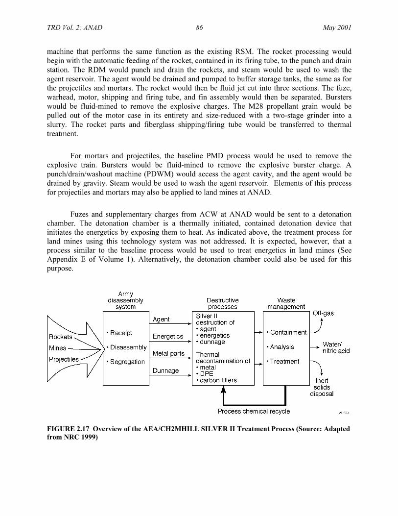
TRD Vol. 2: ANAD 86 May 2001
machine that performs the same function as the existing RSM. The rocket processing wouldbegin with the automatic feeding of the rocket, contained in its firing tube, to the punch and drainstation. The RDM would punch and drain the rockets, and steam would be used to wash theagent reservoir. The agent would be drained and pumped to buffer storage tanks, the same as forthe projectiles and mortars. The rocket would then be fluid jet cut into three sections. The fuze,warhead, motor, shipping and firing tube, and fin assembly would then be separated. Bursterswould be fluid-mined to remove the explosive charges. The M28 propellant grain would bepulled out of the motor case in its entirety and size-reduced with a two-stage grinder into aslurry. The rocket parts and fiberglass shipping/firing tube would be transferred to thermaltreatment.
For mortars and projectiles, the baseline PMD process would be used to remove theexplosive train. Bursters would be fluid-mined to remove the explosive burster charge. Apunch/drain/washout machine (PDWM) would access the agent cavity, and the agent would bedrained by gravity. Steam would be used to wash the agent reservoir. Elements of this processfor projectiles and mortars may also be applied to land mines at ANAD.
Fuzes and supplementary charges from ACW at ANAD would be sent to a detonationchamber. The detonation chamber is a thermally initiated, contained detonation device thatinitiates the energetics by exposing them to heat. As indicated above, the treatment process forland mines using this technology system was not addressed. It is expected, however, that aprocess similar to the baseline process would be used to treat energetics in land mines (SeeAppendix E of Volume 1). Alternatively, the detonation chamber could also be used for thispurpose.
FIGURE 2.17 Overview of the AEA/CH2MHILL SILVER II Treatment Process (Source: Adaptedfrom NRC 1999)

TRD Vol. 2: ANAD 87 May 2001
Slurried explosive material from the ACW (20% by weight) would be sent to a number ofholding tanks for feed to the SILVER II reactor. Agent would be pumped to a buffer area similarto the baseline TOX holding system. Solid secondary wastes (i.e., dunnage) would be size-reduced using two-stage shredders. Metal components, including projectile and mortar bodies,would be thermally treated to a 5X51 condition in a MPT, and dunnage would be thermallytreated in a batch rotary treater (BRT). All process off-gases would pass through a catalyticoxidation unit and through carbon filters prior to release to the atmosphere.
Agents and energetics would be fed into separate SILVER II reactors. A 2-kW unit foragents and a 12-kW unit for energetics were used during demonstration testing. SILVER II is anaqueous electrochemical process, using AgNO3 in concentrated HNO3, in which anelectrochemical cell is used to generate a reactive material (Ag2+) that readily oxidizes organicsubstrates. End products of this oxidation process are primarily CO2 and water. Elements presentin the organic substrate, such as nitrogen, sulfur, or phosphorous are oxidized to nitrate ions,sulfate ions, or phosphate ions. Silver compounds (i.e., chloride) would be recycled or recoveredoff-site, after which it may be returned to the process.
2.2.4.2 History of Destructive Processes
The electrochemical oxidation process is a relatively new technology with respect todestruction of agent or energetics in the stockpile of ACW. The SILVER II process has yet to beused commercially for waste treatment, although a number of tests have been conducted onvarious materials. The type of electrochemical cell used in the SILVER II process is, however,used commercially in the chlor-alkali industry (NRC 1999).
Prior to the PMACWA demonstration, the largest pilot-scale tests for waste treatmenthave been conducted using a 4-kW cell consisting of a single anode-cathode pair. The mostextensive tests have been conducted with spent tributyl phosphate dissolved in kerosene. Thesetests ran continuously for up to 14 days, and 40 gal (150 L) of feed material was destroyed. Theelectrochemical oxidation technology was also successfully tested on 0.35 oz (10-g) batches ofagent at a pilot plant in Porton Down, United Kingdom. The Porton Down unit is similar indesign to the system being proposed for the ACWA program. It includes anolyte and catholytefeed circuits, an anolyte off-gas condenser, an NOx reformer system52 and a modified version ofthe off-gas treatment circuit, including a NaOH scrubber (NRC 1999).
Additional tests on VX have been conducted at Porton Down. The test involved acontinuous run of 6.5 days. At the end of the test, no agent residuals could be detected. The DRE
51 The definition of 5X is provided in Volume 1 of this TRD (see Section 1.2.2.4).52 An NOx reformer is an add-on pollution control device designed to remove NOx after formation. The device uses
water to form nitric acid.

TRD Vol. 2: ANAD 88 May 2001
was calculated at 99.99998%, in terms of organic carbon. With respect to TOC, the DRE wascalculated at 88.7% (NRC 1999).
The NRC has expressed concerns over the electrochemical oxidation process, particularlyin the case of scaling up to meet production schedules and the wide diversity of ACW to bedestroyed. The NRC expressed concern over the ability to maintain appropriate temperatures in ascaled-up system. The set point of the process is 194°F (90°C), and since the process employslarge amounts of electricity, there is a potential problem in controlling those temperatures. Thesecond concern comes from the size of particles. In commercial production, particles areexpected to be larger than those experienced in tests. According to NRC (1999), larger particlestend to limit the feed rates. The NRC indicated that these concerns must be addressed in futuretests, particularly when approaching commercial scale (NRC 1999). Demonstration testing,described below, was intended, in part, to address these concerns.
2.2.4.3 Demonstration Testing53
As discussed for the other technology systems presented in this TRD, baseline reverseassembly, carbon filtration, and the brine reduction operation were not demonstrated as part ofthe demonstration test program. Other unit operations proposed for electrochemical oxidationwere also not selected for demonstration. The following unit operations proposed for SILVER IIwere not selected for demonstration by the PMACWA for the reasons given below.
• Shredder (size reduction). This is common commercial equipment used formarginal size reduction of solid secondary wastes for feed to the BRT.Extensive size reduction capabilities were previously validated by thePMACWA as part of the Demo I and EDS-I.
• RDM. The RDM is a new addition to the proposed full-scale process and wasincorporated after Demo II was conducted (AEA/CH2MHILL 2000). Thepunch and drain stations are based on the existing baseline RSM.
• Cutting Station. The fluid-abrasive cutting and fluid-mining operations aresubstantially similar to the rocket-cutting and fluid-mining technologypreviously validated by the PMACWA as part of the neutralization/biotreatment technology (PMACWA 1999a,b).
53 This material describes the Demonstration II PMACWA program and was based, in part, on PMACWA (2001a).
Because demonstration testing was intended to apply to a variety of ACW from all storage sites, this section doesnot discriminate with regard to munition type and storage installation.

TRD Vol. 2: ANAD 89 May 2001
• M28 Propellant Grinding. Several ACWA technologies require size reductionof M28 propellant. Therefore, the PMACWA elected to conduct a singledesign study (during EDSs) to address this requirement.
• PDWM. The PDWM for projectiles is a new addition to the proposed full-scale process and was incorporated after Demo II was conducted(AEA/CH2MHILL 2000).
• Projectile Burster Washout. This operation is substantially similar to theburster washout technology previously validated by the PMACWA as part ofthe neutralization/biotreatment technology (PMACWA 1999a,b).
• Steam Spray Wash. Water spray washout of ton container vessels and steamwashing of ton container tubing was demonstrated at the ECBC, AberdeenProving Ground, Maryland.
• Detonation Chamber. This device is a contained blast chamber and is acommercially available, indirect, electrically heated vessel.
• MPT and BRT. The MPT and BRT are similar to the MPT previouslyvalidated by the PMACWA as part of the neutralization/biotreatmenttechnology (PMACWA 1999a,b).
• Catalytic Oxidation System. The catalytic oxidation system is commerciallyavailable; it is also similar to the CatOx previously validated by thePMACWA as part of the neutralization/biotreatment technology (PMACWA1999a,b).
• Agent Impurities Removal System (AIRS) and Energetics Impurities RemovalSystem (EIRS). These are new additions to the proposed full-scale processand were incorporated after Demo II was conducted (AEA/CH2MHILL2000).
The reasons for selecting the electrochemical oxidation demonstration unit operations,testing objectives, and significant deviations from the planned testing are discussed in thefollowing subsections. Demonstrations with a 2-kW SILVER II unit (for agents) and a 12-kWSILVER II unit (for energetics) are discussed separately.

TRD Vol. 2: ANAD 90 May 2001
2.2.4.3.1 2-kW SILVER II Unit (Agent)
A 2-kW SILVER II unit was demonstrated to validate destruction of the agents containedin ACW and to correlate with the 12-kW SILVER II unit through testing with agent simulants.The 2-kW SILVER II unit was demonstrated at Building E3566 at the Edgewood Area of APG,Maryland. The demonstration system was an integrated unit consisting of the following:
• Feed System — The agent for each run is pumped from a steel container intotwo premix vessels for metering into the anolyte vessel at an appropriate rate,according to the destruction efficiency of the particular organic material.
• Electrochemical Process — The electrochemical cell contains titaniumelectrodes that are electroplated with platinum. It is designed to operate at amaximum current of 1,000 amps per electrode face; the power supply voltageis automatically varied to maintain the set current. The electrochemical cellconsists of two cathodes flanking an anode. The electrodes are separated intoanolyte and catholyte compartments by membranes made of a perfluoro ion-exchange polymer. The organic feed is metered into the anolyte vessel thatcontains 8-M HNO3 and 10% AgNO3. Fluids from the anolyte circuit flowthrough the channels and are exposed to the anode in the cell. When thecurrent is turned on, the Ag2+ ions generated oxidize the organic feed. SomeAg+ ions and water (as hydrated protons) pass through the electrochemicalcell membrane and flow into the catholyte vessel, which contains 4-M HNO3.The cathodic reaction reduces the HNO3 to NOx and water in the catholytevessel.
• Particulate Removal and Treatment — Silver chloride (AgCl) precipitateswhen chlorinated feeds (i.e., mustard agent) are exposed to HNO3 andAgNO3. The particulate removal process is integrated into the electrochemicalprocess unit; a hydrocyclone54 on the anolyte circuit removes the AgCl beforeit reaches the electrochemical cell. The AgCl accumulates in a separateevaporator oven for 5X treatment. The vapor from the oven passes to acondenser, and the condensate is returned to the anolyte vessel. The AgCl isthen removed as a solid cake for silver reclamation.
• NOx Reformer Circuit — The reactions with Ag2+, which occur in the anolytecircuit, release CO2, CO, and NOx. The reactions occurring in the catholytecircuit release NOx. Off-gas from both circuits passes through a condenser toremove some of the NOx vapors and then travels to the NOx reformer.Because of facility size restrictions, the 2-kW plant included a NOx reformerwith a single column for absorption and distillation. As the gas travels up the
54 A hydrocyclone, also know as a water cyclone, is a device used to separate fluids with different densities.

TRD Vol. 2: ANAD 91 May 2001
column, water running down the column reacts with NOx in the gas to formdilute HNO3. The dilute HNO3 is heated to evaporate water and produceconcentrated HNO3. The evaporated water is condensed and produces verydilute HNO3, which is recycled to the anolyte vessel or disposed of as waste.The concentrated HNO3 is recycled to the catholyte vessel or can be usedcommercially.
• Caustic Scrubber Circuit — Off-gas from the NOx reformer is sent to thecaustic scrubber tower to remove any residual NOx before release of the gas tothe facility ventilation system.
Laboratory-scale testing of a SILVER II agent unit has previously been performed withGB. Destruction of HT and VX has previously been tested at a scale similar to that of thedemonstration unit. Characterization of gaseous, liquid, and solid effluents and verification ofoperating parameters were required. The test objectives of this demonstration unit included thefollowing:
• Validate the ability of the 2-kW SILVER II unit to achieve a DRE of99.9999% for mustard, GB, and VX agents.
• Determine the impact of operations on construction materials to be used in afull-scale system.
• Demonstrate the operation and performance of the following key processcomponents for future scale-up:
- Instrumentation, valves, pumps, etc.
- Hydrocyclone (to determine its ability to deal with solids in the anolytecircuit).
- Electrochemical cell (electrodes and membranes).
• Develop operational data to allow comparison of the 2-kW SILVER II unitwith the 12-kW SILVER II unit for use in scaling up SILVER II.
• Characterize silver-bearing residuals. Determine potential silver recovery anddisposal options (via characterization) for residuals from silver recoveryoperation (mustard agent only).

TRD Vol. 2: ANAD 92 May 2001
• Characterize gas, liquid, and solid process streams from SILVER II forselected chemical constituents and physical parameters, and for the presenceor absence of hazardous, toxic, agent, agent simulant, and Schedule 2compounds.
Significant deviations from the planned demonstration testing included:
• Reduction in the VX validation run quantity (from 22 lb to 9 lb [10 to 4 kg])and duration because of schedule constraints, and
• Elimination of the chloroethyl ethyl sulfide (CEES) validation run because ofdifficulty in obtaining CEES in the quantity needed and schedule constraints.
2.2.4.3.2 12-kW SILVER II Unit (Energetics)
A 12-kW SILVER II unit was demonstrated to validate destruction of the energeticscontained in ACW and to correlate with the 2-kW SILVER II unit through testing withsimulants. The 12-kW SILVER II unit was demonstrated at the Fire Safety Test Enclosure at theAberdeen Test Center, Aberdeen Area of APG, Maryland. The demonstration system was anintegrated unit consisting of the following:
• Feed System — The energetics feed system is designed to maintain theenergetics material in a 20% slurry with water by storing it in a continuouslymixed feed vessel. Two forms of agitation ensure that the energetics remain inthe slurry: an air-driven mixer and a recirculation loop. The energetics slurryis fed to the anolyte vessel by bleeding off a slipstream from the recirculationloop.
• SILVER II System — The SILVER II system of the 12-kW unit is the sameas that for the 2-kW SILVER II unit, except that it does not have a particulateremoval and treatment system.55 It does however, have a complete NOxreformer circuit that includes separate absorption and distillation columns. Asgas travels up the absorption column, water running down the column reactswith the NOx in the gas to form dilute HNO3. The dilute HNO3 leaves thebottom of the absorption column and enters the distillation column, where it isheated to evaporate water and produce concentrated HNO3.
55 No chlorinated feeds were processed in this unit; thus, the particulate removal and treatment system was
removed from the unit.

TRD Vol. 2: ANAD 93 May 2001
Energetics testing in a laboratory scale SILVER II unit was previously performed withRDX, TNT, tetryl, and a double-base propellant similar to M28. Characterization of gaseous,liquid, and solid effluents and verification of operating parameters were required. The testobjectives of this demonstration unit included the following:
• Validate the ability of the 12-kW SILVER II unit to achieve a DRE of99.999% for Composition B (RDX and TNT), tetrytol (tetryl and TNT), andM28 propellant.
• Validate the ability of the 12-kW SILVER II unit to achieve a DRE of99.9999% for dimethyl methyl phosphonate (DMMP), a VX/GB simulant.
• Determine the impact of operations on construction materials to be used in afull-scale system.
• Demonstrate the operation and performance of the following key processcomponents for future scale-up:
- Instrumentation, valves, pumps, etc.
- Electrochemical cell (electrodes and membranes).
- Full-height NOx reformer/silver recovery boiler (ability to maintain H2Obalance).
- Off-gas scrubber operating in conjunction with NOx reformer.
• Develop operational data to facilitate comparison of the SILVER II 2-kWagent system to the 12-kW SILVER II system for use in scaling up theSILVER II agent system.
• Demonstrate the ability or inability to recycle, reuse, or dispose of HNO3.
• Characterize gas, liquid, and solid process streams of SILVER II for selectedchemical constituents and physical parameters and for the presence or absenceof hazardous and toxic compounds.
Significant deviations from the planned demonstration testing included the following:

TRD Vol. 2: ANAD 94 May 2001
• Elimination of the CEES validation run because of difficulty in obtainingCEES in the quantity required and schedule constraints,
• Reduction of the quantity of M28 propellant (from 440 lb to 308 lb [200 to140 kg]) because of schedule constraints, and
• Elimination of planned Composition B testing because of scheduleconstraints.
2.2.4.3.3 Summary of Demonstration Testing
In summary, demonstration testing during Demo II was not as extensive as testing duringDemo I because of the similarity of some of the unit processes and technologies. The 2-kW and12-kW systems were each evaluated during the demonstration. Schedule constraints, however,prevented the PMACWA from completing demonstration testing with VX, some of theenergetics, and CEES simulant. Nevertheless, the PMACWA has determined that SILVER II iseffective in destroying agents and propellant at the targeted levels. However, the curtailedtetrytol demonstration and lack of any demonstration data for Composition B prohibits thecomplete validation of the process. The technology includes operations to effectively processmetal parts and dunnage. Although Composition B has not been demonstrated, greater than99.999% destruction of the constituents of Composition B and tetrytol in laboratory experimentsindicates the likely effectiveness with these energetic compounds (PMACWA 2001b).PMACWA reviews the quality of data generated during demonstration testing in PMACWA(2001f).
On the basis of demonstration testing, the technology provider plans some substantivechanges to the electrochemical oxidation SILVER II technology. One concern with regard toprocess operability is the treatment of burster energetics (tetrytol and Composition B) in theSILVER II system. A limitation of SILVER II was discovered when tetrytol was fed to the12-kW SILVER II demonstration unit at the originally planned feed rates (AEA/CH2MHILL2000). Because SILVER II had problems decomposing an intermediate product, material beganto precipitate within the anolyte circuit. Consequently, the system had to be shut down to clearthe lines. The technology provider’s solution to the precipitation problem was to add ahydrocyclone and a high-speed mixer in the anolyte circuit (AEA/CH2MHILL 2000). Accordingto PMACWA (2001b), there was also a buildup of organics in the catholyte. The catholytecircuit was periodically drained, and the drained catholyte solutions were never reintroduced intothe anolyte. Thus, it is possible that the intermediate product that was concentrating within thecatholyte was only partially treated. A catholyte-to-anolyte recycle stream is proposed to reducethe buildup of organics within the catholyte.
In addition to the above, the technology provider has added a RDM for munitions accessof rockets and a PDWM for munitions access for projectiles. An agent impurities removal

TRD Vol. 2: ANAD 95 May 2001
system (AIRS) and an energetics impurities removal system (EIRS) have also been added to theagent and energetic SILVER II units. These are new additions to the proposed full-scale processthat were incorporated after Demo II was conducted (AEA/CH2MHILL 2000).
Upon incorporation of these changes, the technology provider believes that feed rates canbe increased to the originally planned values. While these proposed improvements all have merit,optimization studies may be required (PMACWA 2001b). Additional details of the results ofdemonstration testing may be obtained from AEC/CH2MHILL (2000) and PMACWA (2001b,c).
2.2.4.4 Engineering Design Studies56
During the demonstration testing described above, electrochemical oxidation wasdemonstrated to be a viable technology system for destroying ACW, in accordance with therequirements of the PMACWA. However, the PMACWA determined that further studies wouldbe necessary in preparation for full-scale pilot design and permitting. Therefore, EDSs will beconducted to provide this information. EDS-II objectives were as follows:
• Provide information for the full-scale facility with respect to total life-cyclecost, schedule, and safety;
• Support the EIS and permit application preparation under RCRA; and
• Support preparation of a RFP for a full-scale pilot plant facility.
As of the preparation of this report, EDS-II plans were not firm and are likely to changeas the program proceeds. However, EDSs for this technology are expected to be ongoing at aboutthe same time that this TRD is published. According to PMACWA (2001a), EDS-II will includefurther investigation of the following issues associated with electrochemical oxidation.
• Modifications to 12-kW plant energetics feed and ancillary systems;
• 500-hour runs of agent simulant and Composition B/M28 propellant with the12-kW plant;
• Laboratory-scale testing on cell membrane life and feeds containing fluoride;
56 This material describes EDSs for the technologies evaluated in the Demo II PMACWA program and was derived
in part from PMACWA (2001a). EDSs for Demo II technologies are designated EDS-II. Because demonstrationtesting was intended to apply to a variety of ACW from all storage sites, this section does not discriminate withregard to munition type and storage installation.

TRD Vol. 2: ANAD 96 May 2001
• Testing of hydrocyclones, high shearing mixing, and organic transfer; and
• Paper studies on projectile burster wash and energetic slurry concentration.
Table 2.4 provides further information on planned EDS-II activities for electrochemicaloxidation. Figure 2.18 is an overview of the electrochemical process and shows unit operationsthat may be further evaluated during EDS-II. Planned evaluations of unit operations areindependent of munition type or agent fill.
TABLE 2.4 Potential Further Studies under Engineering Design Study-II
Test Elements Objectives
Modifications to 12-kW andancillary systems
Provide extended, reliable feed of energetics.
Anolyte and catholyte circuits Implement and demonstrate selected improvements tovessels, piping heating, controls, mixing, andseparation.
Cell membrane life Confirm membrane life over an extended period ofoperation.
Feedstock containing fluoride Confirm transport of fluoride within process andinvestigate methods to mitigate impact on materials ofconstruction.
Hydrocyclone testing Optimize design for removal of process intermediates.
High shear mixer testing Investigate mixing performance for optimal destructionof organics and overall process performance.
Organic transfer across cellmembrane
Investigate migration of organic species across cellmembranes for long-term system performance.
Projectile burster wash Confirm proof of concept and identify designparameters for projectile burster washout.
Energetic slurry concentrationsafety
Assemble and summarize available information toguide energetic slurry management.

TRD Vol. 2: ANAD 97 May 2001
FIGURE 2.18 Flow Diagram of Electrochemical Oxidation SILVER II Process (AEA/CH2MHILLSystem) Showing Units or Operations Undergoing Engineering Design (Source: Adapted fromPMACWA 2001a)
2.2.4.5 Detailed Process Description
This section presents a detailed process description for electrochemical oxidation, asapplied to ACW stored at ANAD, on the basis of demonstration testing results. The equipmentused in a pilot-scale facility may vary in nomenclature and design from that described here,depending on the system selected and system requirements.
Figure 2.19 shows the entire process for electrochemical treatment of ACW at ANAD.Munitions access would use modified baseline reverse assembly. Fuzes, boosters andsupplementary charges would be treated in a detonation chamber. Metal parts from thedetonation chamber, munitions hardware, dunnage, and other solid wastes would be thermallydecontaminated to a 5X condition in either the MPT, an inductively heated vessel with asuperheated steam reactive environment, or the BRT, a rotary version of the MPT with astructure similar to that of the baseline DFS. Steam would be condensed from the MPT or BRTand treated in the SILVER II process. Agents would be drained from the ACW, and energeticswould be removed and slurried.

TRD Vol. 2: ANAD 98 May 2001
NNF - NOT NORMALLY FLOWING
NITRIC ACIDTO SILVERII
CALCIUM HYPOCHLORITEFOR SPOT
DECONTAMINATION
WATERMAKE-UP
ELECTRICALPOWER
STEAM
TBD% HNO3
HTH
COMMON PROCESS
BASELINE PROCESS
UNIQUE PROCESS
MANUAL PROCESS
REAGENT FEED
TRANSFER INREAGENT IN
PROCESSING AREABOUNDARIES
LABEL
(NOTES)
EFFLUENTGAS
MIXED
SOLID
LIQUID
PRE-
TREA
TMEN
TUN
PAC
KING
STEAM
5XPROJECTILE
BODIES
OFFSITEDISPOSAL
OFF-SITERECYCLE RCRA
LANDFILL
POST
-T R
EATM
ENT
Efflu
ent
TREA
TMEN
TACWA
DEMONSTRATEDPROCESS
SHIPPED FEEDS
SODIUM HYDROXIDETO SCRUBBERS &PH ADJUSTMENT
50% NAOH
PRO
JEC
TILE
/MO
RTA
RD
ISAS
SEM
BLY
(PM
D)(2
)
PROJECTILEPALLET
BREAKDOWN
ROCKET PALLETBREAKDOWN
SINGLE,EXPLOSIVELYCONFIGUREDPROJECTILES
SINGLEROCKETS
ROCKET INDEXER
SINGLE ROCKETS
MISCELLANEOUSPARTS REMOVALSTATION (MPRS)
NOSE CLOSUREREMOVAL STATION
(NCRS)
BURSTER REMOVALSTATION (BRS)
MULTIPURPOSELOADER (MPL)(2)
PROJECTILES (ARTILLERY ANDMORTAR SHELLS)
M55 ROCKETS
TOXICCUBICAL(TOX)
TRAYS WITH EGGCRATES
BURSTERFLUIDMINING
FUZES,BOOSTERS
SUPPLEMENTARYCHARGES
PUN
CH/D
RAIN
/W
ASH
OUT
MAC
HIN
E(P
DW
M)
CUTTING WATERRECYCLE SYSTEM
(FILTRATION)GRIT&
WATER
WATER
PROPELLANT SIZEREDUCTION
PUNCH STATION
STEAM WASHSTATION
SINGLE, EXPLOSIVELY INERT PROJECTILES
OFFGAS
METAL PARTSTREATER (MPT)
(ELECTRICINDUCTION)
CONDENSER
CATALYTICOXIDIZER
FAC STATION/PROPELLANTEXTRACTION
PROPELLANT SLURRY
EXPLOSIVESSLURRY
FUZE REMOVAL STATION(FLUID-ABRASIVECUTTING [FAC])
ROCKET DRAIN STATION(RDS)
WITH STEAM SPRAYWASHING
(AGENT RESERVOIR)
BURSTERS
SPENTGRITCAKE
ALL LIQUID SECONDARYWASTES AND CONDENSATES
WATER
ENERGETICSSLURRY TANK
PROPELLANT GRAIN
AGENT & WASH
AGENT
FUZES
AGENT & WASH
DETONATIONCHAMBER
ENE
RGET
ICS
SILV
ER II
ANOLYTECIRCUIT
ELECTRO-CHEMICAL CELL
CATHOLYTECIRCUIT
NOX REFORM-ER CIRCUIT
SCRUBBERCIRCUIT
OFF GAS CONCENTRATEDACID
PROCESSFEED SYSTEM
BLEEDSENERGETICS
IMPURITIES REMOVALSYSTEM (EIRS)
ELECTRO-CHEMICAL CELL
SECONDARYANOLYTEVESSEL
PLUG FLOWREACTOR
BLEED
SETTLING TANK/5XEVAPORATOR OVEN
HCL
AGCL
OFFSITE SILVERRECLAMATION
CONDENSEREVAPORATORCONDENSER
ANOLYTE
GAS
CATHOLYTE
CATHOLYTE
IMPURITIES
CONDENSATE
TRAYED, DRAINEDPROJECTILE BODIES
AGEN
T SI
LVER
II
ANOLYTECIRCUIT
ELECTRO-CHEMICAL CELL
CATHOLYTECIRCUIT
NOX REFORM-ER CIRCUIT
SCRUBBERCIRCUIT
OFF GAS CONCENTRATEDACID
PROCESSFEED SYSTEM
AGENT IMPURITIESREMOVAL SYSTEM
(AIRS)SETTLING TANK/5XEVAPORATOR OVEN
HCL
CONDENSER
DISTILLATIONCOLUMN
CONDENSER
ANOLYTEBLEED
AGCL
DILUTENITRICACID
EVAPORATOR
PH ADJUSTMENT &FLUORINE
PRECIPITATION
ACIDIMPURITIES
AGENT & WASH
SLUDGE
PHADJUSTMENT
OFFSITEWASTEWATER
TREATMENT PLANT
BRINE
EXPLOSIVESSLURRY
RETURN TOENERGETICSSILVER II
ANOLYTE CIRCUIT
RETURNTO
CATHOLYTECIRCUIT
CONDENSATE
DILUTE &CONC.NITRICACIDS
SPENTCATHOLYTE
(NNF)
SPENTANOLYTE(NNF)
SPENTCATHOLYTE
(NNF)
SPENTANOLYTE
(NNF)
ALL DILUTE ACID BYPRODUCTFROM SILVER II
NAOH
DILUTE &CONC.NITRICACIDS
TOATMOSPHERE
CARBON FILTER(HT&R)
GAS EMISSIONS
SIZE REDUCTIONSHREDDERS
STEAM
ROCKETHARDWARE
CONDENSATE
BATCHROTARYTREATER
ELECTROSTATICPRECIPITATOR
CONDENSER
CONDENSATETO
AGENTSILVER II
SHREDDEDSOLIDS
STEAM
ELECTROSTATICPRECIPITATOR
OFF GAS
OFF GAS
QUENCH
OFF GAS
5XSOLIDS
SHRAPNEL
TOCATALYTICOXIDIZER
ALLPROCESS
OFFGAS
OFFGAS
HARD-WARE
OFF GAS
TO CATALYTICOXIDIZER
TOCATALYTICOXIDIZER
NAT'LGAS
AIR
ROCKET DEMILITARIZATIONMACHINE (RDM)
SETTLING TANK/5XEVAPORATOR OVENCONDENSATE
RETURN TO AGENTSILVER II
ANOLYTE CIRCUIT
TOSILVER II
SILVER NITRATE
NAT'LGAS
ALL SOLIDSECONDARY
WASTES
ARTILLERYBURSTERS
AEA04
FIGURE 2.19 Flow Diagram of Electrochemical Oxidation Using the SILVER II Process at ANAD(Source: PMACWA 2001b,c)

TRD Vol. 2: ANAD 99 May 2001
Drained agents and slurried energetics would be treated in separate SILVER II processes.These processes would mineralize the agent and energetics with electrochemical oxidationfacilitated by Ag2+ ions. The SILVER II process would be supported by an agent impuritiesremoval system (AIRS) and an energetics removal system (EIRS). These units each generateprocess solids that would be treated further, as necessary, and disposed of off-site in a RCRAhazardous waste landfill. Silver would be reclaimed off-site, and HNO3 would be generated forreuse in the process. Dilute acid by-product from SILVER II is intended for treatment in an on-or off-site wastewater treatment plant.
All process off-gas would be mixed with air and catalytically converted by the catalyticoxidizer technology, followed by carbon filtration and release to the atmosphere. Treatedmunition bodies (5X condition) would be commercially recycled. Treated solid wastes(5X condition) would be treated further, as necessary, and placed in a landfill as RCRAhazardous waste or disposed of as nonhazardous waste in accordance with regulatoryrequirements.57,58
Short descriptions of each of the unit processes included in the electrochemical oxidationtechnology system are provided below. As indicated previously, the technology provider did notaddress the treatment process for land mines using this technology. It is anticipated, however,that a process similar to the baseline process would be used to access agent and energetics in theland mines (See Appendix E of Volume 1). Following munitions access, the process for treatingspecific agents and energetics would be largely independent of munition type and agent fill.
2.2.4.5.1 Munitions Access – General
The SILVER II process would use modified baseline reverse assembly and fluidaccessing (fluid-abrasive cutting and fluid-mining using water) for ACW pretreatment. Spent gritwould be filtered from the water and sent to thermal treatment; the water would be reused forfluid-abrasive cutting. Slurried explosive material from the ACW (20% by weight) would be sentto a number of holding tanks for feed to the SILVER II reactor circuit. Agent would be pumpedto a buffer area similar to the baseline TOX system. Solid secondary wastes (e.g., dunnage)would be size-reduced using two-stage shredders. Metal parts and dunnage would be treatedthermally to a 5X condition in a manner similar to methods used in other technologies. Detailsfor handling projectiles and mortars and rockets are presented below.
57 Solids treated to a 5X condition to remove residual agent may be defined as hazardous waste if they exhibit any
of the characteristics of hazardous waste as defined in 40 CFR 260.21 – 260.24).58 While these solid wastes are not known to contain chemical agent, they may be defined as hazardous waste if
they exhibit any of the characteristics of hazardous waste as defined in 40 CFR 260.21 – 260.24. These solidsmay contain heavy metals and exhibit the RCRA toxicity characteristic (40 CFR 261.24). In some states, thesolids would be regulated as listed hazardous wastes because of their association with chemical agent. Thesesolids could be “delisted” and not considered hazardous waste if regulatory delisting criteria are met.

TRD Vol. 2: ANAD 100 May 2001
2.2.4.5.2 Munitions Access – Projectiles and Mortars
As indicated above (Section 2.2.4.5.1), projectiles and mortars would be disassembled inthe PMD. They would be received in the unpack area and would be loaded into the existing feedequipment for transportation into the ECR. Two identical disassembly equipment lines areplanned. The PMD would remove the nose closure, burster, fuze, supplemental charge, andmiscellaneous parts. Fuzes and supplemental charges would be conveyed to the detonationchamber for deactivation. The detonation chamber is a thermally initiated, contained detonationdevice that accesses explosive components (i.e., fuzes/boosters, supplementary charges, andigniters) by exposing them to heat. Bursters would be extracted and conveyed to a stand-aloneburster washout machine to fluid jet out the burster, with conventional fluid jet technology. Thiswould result in an energetic slurry with a nominal maximum particle size of 0.02 in. (0.5 m) anda slurry concentration not to exceed 20% by weight.
The burster slurry would feed directly to SILVER II, though some quantity may also bepumped to the energetics buffer storage tank for subsequent processing in SILVER II. The bufferstorage enables the SILVER II plant to operate continuously (if needed). The disassembly plantwould operate 12 hours per day. The maximum quantity of energetic would depend on theenergetic being destroyed.59
A PDWM would access the agent cavity in projectiles and mortars and drain and washthem. The punch and drain machine would extract the liquid agent using punch and draintechnology. Two, 1-in. (2.5-cm) holes, 180° apart at each end, would be punched through thesidewall into the agent reservoir of the projectile. Following draining of the agent, the projectileswould be steamed out to maximize the removal of residual or gelled agent. The agent would bepumped to the agent buffer storage tank and then to SILVER II. The storage tank will bedesigned to operate continuously (if needed). The storage capacity would be 150 gal (568 L).
Projectile and mortar casings from the punch and drain machine would be placed in ametal carrier tray and conveyed to the MPT for 5X treatment. Burster wells, nose closures andfragments from the detonation chamber would all be treated in the metals part treatment processto achieve 5X decontamination.
2.2.4.5.3 Munitions Access – M55 Rockets
M55 rockets would be transported to the unpack area and loaded into the rocket loadingdevice in the same manner as the existing baseline system. Two identical parallel rocketdisassembly lines, each contained in separate ECRs, would be used. The individual rocket wouldbe conveyed through the air lock and into the ECR, which contains the rocket demilitarization 59 Storage capacity, spread across a number of tanks, would be 1,500 lb (680 kg) of M55 rocket propellant, or
significantly lower quantities of high explosive.

TRD Vol. 2: ANAD 101 May 2001
machine (RDM). The RDM is a new machine that performs the same function as the existingRSM. The rocket processing would begin with the automatic feeding of the rocket, contained inits firing tube, to the punch and drain station. This would be based on the existing punch anddrain process, but with the addition of a final steam-out to remove residual agent. The agentwould be drained and pumped to buffer storage tanks, the same as for the projectiles and mortars.The rocket would then be fluid jet cut into three sections. A fuze cut would be made to separatethe fuze and expose the burster section. A tail cut would be made to separate the tail section andexpose the bottom end of the propellant grain for subsequent extraction. Disposition ofindividual rocket components would be as follows:
• The fuze sections would be deposited in mesh containers and conveyed to thedetonation chamber for destruction.
• The warhead section would be conveyed to the burster washout station wherethe burster would be washed out. This would result in an energetic slurry witha nominal maximum particle size of 0.02 in. (0.5 mm) and a slurryconcentration not to exceed 20% by weight. The slurry would feed directly toSILVER II, though some quantity may also be pumped to the energeticsstorage tank as discussed previously. The warhead section would then bedeposited in a container tray and conveyed to the metal parts treatmentprocess. The container tray typically holds 10 to 15 warhead sections.
• The rocket motor and tail section would be conveyed to the propellantremoval station where the M28 propellant grain would be pulled from themotor casing. The motor and tail section would be deposited in a containertray for subsequent metal parts washing. The propellant would be conveyed tothe propellant size reduction station.
• Fiberglass firing tube sections would be deposited in a container tray andconveyed to the dunnage treatment process for thermal treatment to a 5Xcondition.
2.2.4.5.4 Munitions Access – Land Mines
The technology provider did not address how it would pretreat land mines in preparationfor either agent or energetics treatment. Without this information, it is assumed that agent andenergetics would be accessed from land mines in a manner similar to the baseline technology(see Volume 1, Appendix E for a detailed discussion). In addition, elements of the munitionsaccess process for projectiles and mortars (see Section 2.2.4.5.2) could be applied to land mines.Of the four sites being evaluated in this TRD, only ANAD and PBA contain land mines.

TRD Vol. 2: ANAD 102 May 2001
2.2.4.5.5 Agent and Energetics Treatment
Agents and energetics would be destroyed using electrochemical oxidation in theSILVER II process. SILVER II is a mediated electrochemical oxidation process using Ag2+ ionsin aqueous HNO3 (formed by an electrochemical cell) that is circulated through CSTRs (anolyteand catholyte circuits). The electrochemical oxidation process uses essentially the same systemfor destroying both agent and energetics. During demonstration testing, agent was destroyed in a2-kW electrochemical cell (Figure 2.20), while energetics were destroyed in a 12-kW cell(Figure 2.21). Drained agent, along with liquids condensed from the BRT and MPT (see below),would be destroyed in the agent SILVER II unit. Propellant and high explosives (from bursters)would be destroyed in the energetics SILVER II unit. It is possible that the same kW systemswould be used for agent and energetics in the pilot-scale design.
The SILVER II unit would consist of a feed system, an anolyte circuit, and a catholytecircuit integrated with a NOx reformer and agent and energetics impurities removal systems(AIRS and EIRS, respectively). It is operated at a temperature of 190°F (90°C) and nearatmospheric pressure. SILVER II, originally a semicontinuous batch process, is made acontinuous process through a “bleed” to IRSs. The AIRS and the EIRS would be used forimpurities removal. In these removal systems, a purge stream would be withdrawn from theanolyte reservoir. The rate is designed to limit the concentration of impurities in the anolyte toapproximately 1-M phosphate and sulfate in order to avoid precipitation of their silver salts.Other impurities of lower flux (such as iron, aluminum, etc.) would be maintained atsignificantly lower concentrations as a result. In order to recover the silver for reuse,hydrochloric acid would be added to precipitate it as the chloride (AgCl). The silver would berecovered by either gravity settling or in a hydrocyclone. As AgCl may contain small traces ofagent, AgCl would be treated to a 5X condition prior to being sent for silver recovery. Thecondensate from this process would be returned to the catholyte of the SILVER II system. Theprecipitator overflow would then be fractionally distilled to recover water and HNO3 for recycleto the SILVER II catholyte (to create the AIRS and EIRS purge flow returns). The evaporatorbottoms would contain some residual HNO3 as well as enriched phosphoric and sulfuric acids.These, together with the HF stream, would subsequently be neutralized with lime to precipitateinsoluble fluoride, phosphate, and sulfate salts of calcium. This stream could then be treated to a5X condition. The condensate would be returned to the catholyte of the SILVER II system.
The SILVER II process is based on the highly oxidizing nature of Ag2+ ions in a HNO3solution. Ag2+ ions are among the strongest oxidizing agents known; while HNO3 also makes asignificant contribution to the oxidizing process (NRC 1999). The Ag2+ ions are produced at theanodes of an electrochemical cell (NRC 1999). The overall chemical reaction can be summarizedas follows:
Organic + AgNO3 + HNO3 + electrical current = CO2 + mineral acids + water + NOx.

TRD Vol. 2: ANAD 103 May 2001
FIGURE 2.20 Process Flow Diagram for a SILVER II 2-kW Agent PlantUsed in Demonstration Testing (Source: Adapted fromAEA/CH2MHILL 2000)
FIGURE 2.21 Process Flow Diagram for a SILVER II 12-kW EnergeticsPlant Used in Demonstration Testing (Source: Adapted fromAEA/CH2MHILL 2000)

TRD Vol. 2: ANAD 104 May 2001
Generation of Ag2+ ions depends entirely on the electrical current, and it stops when thepower is switched off. This process ensures that the reaction is easily controllable. Electricalpower to the cell can be shut off safely at any time (e.g., from safety interlocks at other stages ofthe overall process). A standard industrial electrochemical cell is at the heart of the SILVER IIprocess. Figure 2.22 is a schematic of the 2-kW electrochemical cell; Figure 2.23 is a schematicof the 12-kW system used in demonstration testing. Again, it is probable that the same anodecathode arrangement may be used for agent and energetics in the pilot-scale design.
The anode and cathode compartments of this cell are separated by a permeable membranethat prevents bulk mixing of the anolyte and catholyte solutions. These solutions are circulatedaround separate closed loops between the cell and their reaction vessels. The organic material fordestruction is continuously metered into the anolyte tank to match the rate of destruction.
Ag2+ ions generated at the anode of the electrochemical cell react with the water andHNO3 of the anolyte solution to form a range of other oxidizing radicals (·OH, ·NO3). In turn, theAg2+ ions and other oxidizing species react with the organic material delivered into the anolytevessel and are reduced to Ag1+ ions, nitrate ions, and water. The organic material is oxidized toO2, NOx (from the direct reaction with the acid) and traces of CO and protons (H+, not hydrogengas), and inorganic salts. Off-gas from the reaction passes from the anolyte vessel via acondenser (to return HNO3 and organic vapors) to an NOx reformer.
FIGURE 2.22 2-kW Anode/Cathode Arrangement Used inDemonstration Testing. (Source: Adapted fromAEA/CH2MHILL 2000)

TRD Vol. 2: ANAD 105 May 2001
FIGURE 2.23 12-kW Anode/Cathode ArrangementUsed in Demonstration Testing (Source: Adaptedfrom AEA/CH2MHILL 2000)
To balance the electrochemical reaction in the anolyte, a supporting cathode reactionoccurs that involves reducing HNO3 to nitrous acid and water, while other reduction reactionsgenerate NO/NO2. The gases pass from the catholyte tank to the NOx reformer. The process isoperated at a temperature of approximately 190°F (90°C) and at atmospheric pressure. As aresult of the electrochemical reaction, HNO3 is consumed in the catholyte circuit, which resultsin the formation of gaseous NOx. Water is transferred across the membrane in theelectrochemical cell from the anolyte to the catholyte. In addition, Ag1+ ions are also transferredacross the cell membrane, together with a small amount of organic material, depending on theorganic feed to SILVER II. To maintain steady-state operating conditions, the operationincorporates internal recycle streams to return the silver and organic material to the anolytecircuit. This ensures that a buildup of organic material or silver in the catholyte does not occur,and that steady-state conditions can be maintained.
The off-gas streams from the anolyte and catholyte circuits are combined and sent to theNOx reformer system. The reformer recovers the NOx by removing it from the gas stream andrecycling it into concentrated HNO3 for return to the anolyte and catholyte circuits as required;or alternatively, the excess can be marketed as a product. A dilute HNO3 stream of less than 1%weight is also produced. The technology provider plans to send this material to either on- or off-site wastewater treatment. The dilute HNO3 stream may also be recycled within the plant.
The post-treatment portion of SILVER II also consists of a caustic scrubber circuit, and anumber of CSTRs for adjusting the pH. NOx in the off-gas is collected by a NOx absorbercolumn and reformed to HNO3, which is concentrated in a packed bed distillation column. Theremaining off-gas from the NOx reformer goes to a caustic scrubber for acid neutralization.

TRD Vol. 2: ANAD 106 May 2001
Hydrofluoric acid distilled by the agent impurities removal system (AIRS) is neutralized withlime in a CSTR. Similarly, dilute HNO3 waste is pH neutralized with caustic.
After leaving the NOx reformer, all off-gas passes through a caustic scrubber to removevery low levels of residual NOx, thus leaving a stream of CO2, oxygen, and water vapor. Theoff-gas is then tested to ensure that no agent is released from SILVER II. This off-gas stream isthen processed through the catalytic oxidation process as a polishing step to ensure that traceorganics are destroyed. Silver chloride (AgCl) is precipitated when mustard agent is exposed tothe HNO3 and AgNO3 in the anolyte vessel. In the anolyte circuit, a hydrocyclone is used tocontinuously remove the AgCl from the recirculating liquid before it reaches the electrochemicalcell.
The AgCl is accumulated in a settling vessel and discharged into an oven for5X treatment on a batch basis. The vapor from the oven is passed to a condenser and thecondensate is returned to the anolyte vessel for destruction of any organic material that may bepresent. The AgCl is then removed as a solid cake for silver reclamation. Silver reclamation maybe conducted on- or off-site.
2.2.4.5.6 Metals Parts Treatment
Metal parts would be treated to achieve a 5X condition in the MPT, as explainedpreviously. The objective of this unit operation would be to elevate the temperature of the partsto over 1,000°F (538°C) for a period of at least 15 minutes. The PMACWA previouslydemonstrated this concept at CAMDS and during the ACWA Demo I. Metal parts treatmentwould be accomplished in a chamber designed to receive the various metal parts containers, suchas the projectile casing conveyance trays. The metal parts containers would be automaticallyconveyed into the chamber. The chamber would use electrical heating elements to achieve thedesign temperature. Steam would be passed through the chamber to enhance the exposure ofmetal to elevated temperatures and to establish the conditions of 5X treatment. The dischargedsteam would be condensed, and the off-gas would be sent to the catalytic oxidation process fordestruction of trace organic compounds, and then to carbon filtration, before discharge to theatmosphere. Two decontamination chambers would be used so that one chamber would be inload and 5X treatment phase, while the second chamber would be in the cool-down and unloadphase. Decontaminated metal parts would be transported off-site for either recycle or disposal, inaccordance with regulatory requirements.
The specific design of the detonation chamber would be optimized during EDS-II. Theconceptual design, however, indicates that two detonation chambers would be sufficient toprovide adequate capacity and to provide redundancy to deactivate fuzes, boosters, andsupplemental charges. The chamber would be loaded with a preapproved number of fuzes anddetonation charges. The controlled detonation would deactivate the fuzes. The resulting metalfragments would be conveyed to the metal parts treatment process. Off-gas from the chamber

TRD Vol. 2: ANAD 107 May 2001
would be processed through the catalytic oxidation process and subsequently through carbonfilters prior to discharge.
2.2.4.5.7 Dunnage Treatment
Dunnage treatment would use the same principle as that for metal parts to achieve 5Xdecontamination. Contaminated dunnage would be stored in a silo contained within the MDBand would be fed to a two-stage shredder for size reduction to nominal 2 to 3 in. (5 to 8 cm)particle sizes. This would be accomplished using commercially available shredding equipment.The shredded dunnage would be mechanically conveyed to the BRT. As indicated previously,this is essentially the same as the MPT, except that it is a rotary oven that operates as acontinuous process. The chamber would be designed to expose the shredded dunnage to thedesign temperature for a resident time of 30 minutes to provide a reasonable safety factor.Treated dunnage would be discharged into a storage hopper for subsequent placement in alandfill, in accordance with regulatory requirements.
The BRT thermally treats fluid-cutting grit and size-reduced, solid (mostly nonmetallic)secondary wastes (dunnage and rocket shipping and firing containers). The BRT is similar to theMPT; however, it is operated in continuous mode. Off-gas from the MPT and the BRT (mostlysteam) would be condensed and sent to SILVER II for treatment. All process off-gas would bemixed with air, treated with a catalytic oxidation system, and passed through carbon filtersbefore release to the atmosphere.
2.2.4.5.8 Effluent Management and Pollution Controls
The SILVER II process produces various types of waste. The process off-gases arepassed through a catalytic oxidation unit, carbon filtered, and tested (with carbon filter rework asnecessary) before exhausting to the atmosphere. Liquids are separated by evaporators andcondensers and are reused (on- or off-site) or sent off-site for treatment, as necessary, anddisposal. Evaporator bottoms from the impurities removal systems are treated, as necessary, anddisposed of off-site. The pH-adjusted acid streams would undergo wastewater treatment eitheron- or off-site. Solids from HF neutralization would be dewatered in a filter press and would betreated as necessary and placed in a landfill. Metals that have been decontaminated to a 5Xcondition would be recycled, and 3X and 5X solids would be treated as necessary and placed in alandfill. All waste management would be conducted in compliance with regulatory requirements.As indicated previously, wastes determined to be hazardous may be delisted from beinghazardous waste if regulatory delisting criteria are met.
Silver is used to catalyze the oxidation of organics. Normally, this silver remains insolution, except in those instances when compounds containing chlorine are present. Silvercombines with chlorine (contained in mustard) to create AgCl, which must be removed from the

TRD Vol. 2: ANAD 108 May 2001
system. This is accomplished by using hydrocyclones that separate the precipitated AgCl fromthe anolyte solution in the plant. The material is then decontaminated in a 5X oven. The resultingmaterial would be collected and transported off-site. Silver would be reclaimed at a commercialfacility. If necessary, this reclamation process can occur on-site. Silver sent off-site would needto be treated to achieve a 5X condition.
Concentrated HNO3 is a product of the SILVER II process when treating energeticmaterials that contain nitrogen. These materials can be transported off-site for reuse in themanufacture of energetics. Dilute HNO3 is also produced. This material could be recycled withinthe system. Any unrecycled dilute HNO3 would be neutralized with scrubber waste anddischarged to on-site or off-site wastewater treatment. Any materials sent off-site would need tomeet Army safety standards.
2.2.4.6 Common Elements – Other Systems
The electrochemical oxidation process has several elements that are identical or nearlyidentical to other systems. This commonality is particularly evident in pretreatment processes.Commonalities with other applicable technology systems include the following:
• The munitions access system used for electrochemical oxidation usingSILVER II employs much of the baseline reverse assembly system, as domost of the other ACWA systems.
• Similar to the neutralization/biotreatment process, the munitions accesssystem for the M55 rockets employs fluid jet cutting and fluid-mining toaccess energetics.
• Process off-gas is passed through catalytic oxidation units prior to carbonfiltration and release to the atmosphere. This is also similar to theneutralization/biotreatment process, as well as the neutralization/GPCR/TW-SCWO process.
• Dunnage would be size-reduced and treated in a manner similar to theneutralization/biotreatment technology.
• Decontamination of metal parts would occur thermally to a 5X conditionusing steam. The process would subject the parts to temperatures in excess of1,000oF (538o C) for a period of more than 15 minutes. This process is similarto that used in the neutralization/biotreatment technology.

TRD Vol. 2: ANAD 109 May 2001
Facility structure; ventilation; decontamination fluid supply; personnel support; pollutionabatement; water, air, and steam supply; control rooms; monitoring systems; and laboratorysupport would be identical or nearly identical to the baseline system.
2.2.5 COMBINATION TREATMENT TECHNOLOGIES
Given the commonalities of the various technology systems, the elements of the variousunit operations could be combined into different but viable ACW treatment alternatives. Anumber of different combination technologies may be considered. The following are examples ofseveral combination technologies that could be employed:
• The cryofracture technology of neutralization/SCWO can be used with anysystem,60
• The fluid-abrasive cutting and fluid-mining technologies of neutralization/biotreatment can be used with any system,
• The specific units proposed for agent and energetic hydrolysis in either of theneutralization/SCWO, neutralization/biotreatment, or neutralization/GPCR/TW-SCWO systems are interchangeable,
• The metal parts treatment technologies proposed for either neutralization/SCWO, neutralization/biotreatment, or neutralization/GPCR/TW-SCWO areinterchangeable,
• The CatOx unit used in neutralization/biotreatment, neutralization/GPCR/TW-SCWO, and in electrochemical oxidation can be employed with anytechnology system, and
• Carbon filtration as used in the baseline process and in most of the ACWAtechnologies may be used with any technology system.
60 This process, however, may not perform well with aluminum-bodied munitions such as M55 rockets.

TRD Vol. 2: ANAD 110 May 2001
[This page intentionally left blank.]

TRD Vol. 2: ANAD 111 May 2001
2.3 SUPPLEMENTAL INFORMATION FOR ASSEMBLED SYSTEMSAT ANNISTON ARMY DEPOT
This section provides supplemental information for pilot testing ACWA technologysystems at ANAD. Included are facility descriptions, system inputs and resource requirements,routine emissions and wastes, and activities and schedules. This section addresses constructionand operation of the facility. As the pilot-scale facility designs mature, deviations are expected.However, it is anticipated that the final design would result in estimates similar to those providedin the tables in this section.
2.3.1 GENERAL FACILITY LOCATION AND FOOTPRINT
For the purposes of NEPA assessment, it has been assumed that all ACWA programfacilities would be constructed within the boundaries of ANAD. Figure 2.24 shows the threeproposed sites (Sites A, B, and C) for the demilitarization facility within the northern half of thedepot. All three sites are adjacent to the existing ACW storage area; two are to the north and oneis to the west. The exact location of the actual destruction facility within these three areas has yetto be determined. It is possible that multiple ACWA technologies could be tested at ANAD.
In general, the physical size of the destruction facility for ACW at ANAD is expected tobe comparable to that required for baseline incineration. The facility size may differ slightly as afunction of technology system alternative. For each technology system, the facility is expected tocover an area approximately 20 to 30 acres (8 to 12 ha), with additional land area of up to20 acres (8 ha) needed for construction support facilities. Additional acreage may be required foraccess roads and utilities; the area required would be determined on a site-specific basis. Thefacility size may differ slightly as a function of the technology system alternative. Table 2.5provides distance information for each of the three sites, and Table 2.6 provides land arearequirements during operations.
The land area required during construction may be greater than that required duringoperations because of the need for the following:
• A construction lay-down area for temporary storage of construction materialssuch as structural steel, pipe, lumber for concrete forms, and electricalconduit;

TRD Vol. 2: ANAD 112 May 2001
FIGURE 2.24 Map Showing Three Potential Locations for the Demilitarization Facilityat ANAD

TRD Vol. 2: ANAD 113 May 2001
TABLE 2.5 Approximate Distances from PotentialDemilitarization Facility Locations A, B, and C to ANADInstallation Boundaries (mi)a
Location
Distance toNorth ANAD
Boundary
Distance toSouth ANAD
Boundary
Distance toEast ANADBoundary
Distance toWest ANAD
Boundary
A 0.8 4.2 0.2 3.8B 0.3 4.8 2.7 2.2C 1.4 3.5 3.0 2.5
a Distance determined (in miles) from the approximate midpoint of AreasA, B, and C, respectively, as shown in Figure 2.11.
TABLE 2.6 Land Area Requirements during TechnologySystems Operations
Technology Land Area for Operations (acres)
Baseline incineration 20Neutralization/SCWOa 20–30Neutralization/biotreatmentb 20Neutralization/GPCR/TW-SCWOc 25Electrochemical oxidation 20
a Based on Figure 4.3-8 in General Atomics (1999).b Based on Figure 4.3.1-1 in Parsons/Allied Signal (1999) and
stated similarity to incineration facility layout.c Based on PMACWA (2001c).
• Temporary construction offices for housing on-site engineering personnel andconstruction supervision and management personnel;
• Temporary parking for construction workers and support personnel;
• Temporary holding basins for control of surface water runoff duringconstruction; and
• Areas for installing required temporary utilities and services, includingconstruction service water, sanitary facilities, electrical power, and vehiclefuels.

TRD Vol. 2: ANAD 114 May 2001
The additional land area for construction-related activities would, in general, be on theorder of 10 to 20 acres (8 to 12 ha). This analysis conservatively assumes that a total of 50 acres(20 ha) would be required for construction purposes. Examination of the available land area atsites A, B, and C indicates that the above construction-related areas would be readily available ateach of these locations. Security fencing would be installed so that the destruction sites would besurrounded by a continuous fence.
All three areas (A, B, and C) have terrain that can accommodate planned construction.Construction of the demilitarization facility would involve small amounts of excavation and fillwork. Construction debris would be transported off-site to a commercial disposal facility. Adrainage system would be established for the facility to divert surface runoff from the plant siteand prevent erosion and accumulation of surface water on the facility. Clearing and earthworkwould be required in the three areas.
2.3.2 NEUTRALIZATION/SCWO
This description of the neutralization/SCWO facility is based on preliminary designinformation provided in General Atomics (1999). The PMACWA and the technology providerhave supplied information on application of this technology to PCD and BGAD (PMACWA1999a,b) but not to ANAD (General Atomics 1999). Therefore, the information and estimatesprovided for this installation are based, in part, on information provided for application of thistechnology to PCD and BGAD. In that report (General Atomics 1999), many of the estimatesprovided for facility design refer comparatively to the U.S. Army baseline incineration process,which indicates, in general, that estimates are comparable to those associated with the baselineincineration process. Thus, one of the primary sources of information for this section is the EISfor disposal of chemical agents and munitions stored at Pine Bluff Arsenal, Arkansas (PMCD1997b). That is the most recent EIS that the U.S. Army has prepared for baseline incineration ofchemical munitions.
In addition to the above, mass balance estimates, air emission estimates, and solid wasteestimates for application of the neutralization/SCWO technology at ANAD have been prepared(Mitretek 2001b). Air emissions and solid waste estimates for neutralization/SCWO, asdiscussed below, are based on Mitretek inputs (Mitretek 2001b), along with appropriateassumptions on filtration systems and plant operations schedule. Figures 2.25 and 2.26 providean input/output material balance for the major steams for neutralization/SCWO of ACWcontaining mustard and nerve agent.
Many of the figures and tables referred to in the facility description for this technologysystem contain estimates (e.g., emissions, resources consumed) associated with processing ACWwith a specified agent; these estimates are given on an annual basis (e.g., tons/yr). In some cases,the estimates have been converted from other units (e.g., lb/d) by accounting for the number ofdays of operation required for processing a specific type of ACW. This time period is referred to

TRD Vol. 2: ANAD 115 May 2001
FIGURE 2.25 Input/Output Material Balance for Neutralization/SCWO of ACWContaining Mustard Agent at ANAD
as a campaign; a campaign is agent-specific. The values in many of the following figures andtables are based on the number of days in the campaign required to process ACW containing aspecific agent. It was assumed that there are 276 operating days in a year. If the campaign is lessthan or equal to 276 days, annual quantities equal total quantities. If the campaign is greater than276 days, quantities in the figures and tables are for 276 days of processing. In the latter case, theestimates provided are less than total quantities. Daily (or other) quantities may be obtained byadjusting for the number of days in the campaign.
2.3.2.1 General Facility Description
The proposed neutralization/SCWO facility is designed to fit into approximately the samespace and general configuration as the baseline incineration process. Munitions access anddisassembly, base hydrolysis, and SCWO operations have been substituted for incinerationoperations. The physical plant consists of a two-story building constructed of noncombustiblematerials, with a concrete structural frame and a low-slope concrete roof.

TRD Vol. 2: ANAD 116 May 2001
FIGURE 2.26 Input/Output Material Balance for Neutralization/SCWO of ACWContaining Nerve Agent at ANAD
The site layout for the neutralization/SCWO facility is shown in Figures 2.27 through2.29. Figure 2.27 shows the general facility layout, Figure 2.28 shows the layout of the firstfloor, and Figure 2.29 shows the layout of the second floor. Additional diagrams may be found inGeneral Atomics (1999).
2.3.2.2 Construction Phase
The schedule for destruction of the stockpile at ANAD, although tentative, calls forconstruction of the selected alternative to begin following issuance of the EIS Record ofDecision (ROD) and receipt of the RCRA and any other required environmental permits, asnecessary. It is anticipated that the construction schedule for the neutralization/SCWO facilitywould not differ significantly from that required for baseline incineration. Construction wouldtake approximately 32 months, including a 15-month site preparation period (PMCD 1997a).However, the PMACWA is investigating means of shortening the construction phase.
Construction of the destruction facility on the ANAD installation would result in vehicleexhaust emissions, fugitive dust, noise, destruction of wildlife habitat and native vegetation,increased employment, increased demand for public services, and occupational health hazards.

TRD Vol. 2: ANAD 117 May 2001
FIGURE 2.27 Neutralization/SCWO Facility Arrangement at ANAD (Source: GeneralAtomics 1999)
2.3.2.2.1 Construction Inputs and Resource Requirements
The capital cost for the neutralization/SCWO process at ANAD is not available and wasestimated by taking into account the variation in chemical agent compared with BGAD andPCD, for which capital cost estimates are available (PMACWA 1999b). For purposes of theenvironmental data for this report, site conditions were assumed to be similar to the ElectricPower Research Institute (EPRI) Standard Hypothetical East/West Central Site as defined inAppendix F of the U.S. Department of Energy (DOE) Cost Estimate Guidelines for AdvancedNuclear Power Technologies (Delene and Hudson 1993). (Detailed information concerning thepresent design of the incineration facility at ANAD was unavailable for this analysis.)
Resources needed for facility construction include water, electricity, concrete, steel,liquid fuels, lumber, and industrial gases (e.g., propane). Table 2.7 provides estimates of theprimary construction materials that would be consumed during construction.

TRD Vol. 2: ANAD 118 May 2001
FIGURE 2.28 Layout of First Floor of the Munitions Demilitarization Building for theNeutralization/SCWO Facility at ANAD (Source: General Atomics 1999)
The estimated values in Table 2.7 were compared with the material quantities for achemical demilitarization incineration facility at ANAD (Templin 2000), as shown in Table 2.8.The estimates for concrete and steel are within 10% of each other, although the estimates forother construction materials for this study are less than those for the incineration facility. Thesedifferences may be due to the location of service pipelines assumed in this study.
The process equipment would be purchased from equipment vendors. Specialty materials,such as Inconel or Monel, do not appear to be required. However, the SCWO reactors mayrequire platinum or an alternative specialty liner as an anticorrosive barrier in the final design(PMACWA 1999a).
Table 2.9 provides an order-of-magnitude estimate of the number of shipments ofconstruction materials to the site. The estimate does not include process equipment and relateditems; the number of shipments associated with these resources is expected to be small incomparison with the estimate of 5,000 total shipments.

TRD Vol. 2: ANAD 119 May 2001
FIGURE 2.29 Layout of Second Floor of the Munitions Demilitarization Building for theNeutralization/SCWO Facility at ANAD (Source: General Atomics 1999)
An order-of-magnitude estimate of the emissions from construction delivery vehicles tothe site is provided in Table 2.10. A one-way trip distance of 20 mi (32 km) and delivery byheavy-duty diesel trucks are assumed. The actual trip distances would depend on a number offactors, including the availability of construction materials from local distributors and thedistance of the site from local distributors.
2.3.2.2.2 Construction Workforce
The construction workforce is expected to steadily increase to a peak of about 910 full-time equivalent (FTE) employees near the midpoint of the construction period, and then todecrease steadily until construction is completed. The average number of construction workers isestimated to be approximately 450 FTEs. Assuming a 32-month construction period,approximately 1,200-FTE-years of effort would be expended during construction.

TRD Vol. 2: ANAD 120 May 2001
TABLE 2.7 Estimated Materials/Resources Consumedduring Construction of a Neutralization/SCWO Facilityat ANADa
ConstructionMaterial/Resource
TotalConsumption
PeakDemand
Utilities Waterb 8,000,000 gal NAc
Electricity 50,000 MWh 2.5 MWSolids Concrete 32,000 yd3 NA Steel (structural and reinforcing) 7,100 tons NA Piping (all) 123,000 linear ft NALiquids Fuel 2.4E+06 gald NAGases Industrial gases (propane) 6,400 gal NA
a All values can be considered order-of-magnitudeapproximations of the actual values; more accurate valueswould require a detailed consideration of constructionactivities.
b The water requirement was estimated on the basis of DOE(1997), in which each full-time equivalent (FTE) required20 gal/d, and solidification required 26.1 lb per 100 lb ofcement.
c NA = not applicable.d This system of exponential notation is equivalent to N × 10x;
for example, 2.4E+06 equals 2.4 × 10⁶.
TABLE 2.8 Comparison of Estimated Materials/Resources with Valuesfor a Typical Chemical Demilitarization Incineration Facility
Material/ResourceValues in
Templin (2000)Values in
This StudyVariance
(%)
Pipe (process, utility, and civil)(linear ft)
256,000 123,000 -108
Structural steel (tons) 6,110 7,100 14Concrete (yd3) 29,000 32,000 9Excavated material (yd3) 268,000 45,720 -486Electrical wire and cable (linear ft) 3,379,000 593,500 -469Electrical conduit (linear ft) 558,000 89,500 -523

TRD Vol. 2: ANAD 121 May 2001
TABLE 2.9 Order-of-Magnitude Estimate of theNumber of Truck Shipments of Construction Materialsfor a Neutralization/SCWO Facility at ANADa
ResourceTotal
ConsumptionTruck
CapacityNo. of TruckShipments
Portland cementb 3,520 yd3 10 yd3 352Gravelb 13,120 yd3 10 yd3 1,312Sandb 8,320 yd3 10 yd3 832Steelc 7,100 tons 21 tons 340Asphalt pavingd 1,400 tons 20 tons 70Backfille 12,800 yd3 10 yd3 1,280Fuelf 2.4E+06 gal 9,000 gal 270Total 4,456Total (rounded up) 5,000
a The calculation did not include truck deliveries of processequipment and related items.
b Assumes that concrete is composed of 11% portlandcement, 41% gravel, and 26% sand and is shipped to thesite in a standard 10-yd3 end-dump truck.
c Assumes that the net payload for steel transport to the siteis 42,000 lb.
d Assumes that hot mix asphalt (HMA) is loaded into 20-ton-capacity triaxle trucks for transport to the paving site.
e Assumes that shipment is in standard 10-yd3 end-dumptrucks.
f Assumes that shipment is in a U.S. Department ofTransportation (DOT) 406/MC-306 atmospheric pressuretank truck with a 9,000-gal capacity.
The peak construction employment of 910 is approximately 17% greater than the targetpeak workforce of about 780 FTEs for construction of the baseline incineration facility at ANAD(Templin 2000). Table 2.11 provides an estimate of the employment buildup by year duringconstruction.
2.3.2.2.3 Construction Emissions and Waste Estimates
During the construction phase, fugitive emissions would consist mainly of dust andvehicle exhaust. Temporary, regional increases in atmospheric concentrations of carbon

TRD Vol. 2: ANAD 122 May 2001
TABLE 2.10 Estimated Emissions from Delivery Vehicles during Construction of aNeutralization/SCWO Facility at ANAD
CriteriaPollutanta
No. of AutoRound Tripsb
EmissionFactor (g/km)c
One-Way TripDistance (mi)d
ConstructionPeriod (yr)
Emission Rate(tons/yr)
HC 5,000 2.12 20 2.8 0.3CO 5,000 11.28 20 2.8 1.4NOx 5,000 1.25 20 2.8 0.2SOx 5,000 0.23 20 2.8 0.03PM10 5,000 0.617 20 2.8 0.1
a Abbreviations: CO = carbon monoxide, HC = hydrocarbons, NOx = nitrogen oxides,PM10 = particulate matter less than or equal to 10 micrometers, SOx = sulfur oxides.
b Number of auto round trips to the construction site was estimated on the basis of thetotal number of deliveries.
c Emission factors were determined by using U.S. Environmental Protection Agency(EPA) modeling software MOBILE5b (EPA 2000c) for HC, CO, and NOx and PART5(EPA 2000b) for PM10.
d One-way trip distance based on DOE (1997).
TABLE 2.11 Estimated Number of Employees Needed by Yearfor Construction of a Neutralization/SCWO Facility at ANAD
Employees Year 1 Year 2 Year 3
Total craft workers 280 560 130Construction management and support staff 70 140 30Total 350 700 160
monoxide (CO), nitrogen oxides (NOx), hydrocarbons, particulate matter, and sulfur oxides(SOx) would result from the exhaust emissions of commuter vehicles, heavy constructionvehicles, diesel generators, and other machinery and tools. Annual emissions of these pollutantswould be small in comparison to de minimis levels typically used by regulators to determinewhether an air quality permit or impact analysis is necessary. Construction vehicle emissions areexempt from permit requirements. Nevertheless, vehicles and machinery would be equipped withstandard pollution control devices to minimize air quality impacts.
Estimated criteria pollutant emissions from construction activities (not includingemissions from delivery vehicles) are shown in Table 2.12. The emissions shown are based onthe anticipated construction land disturbance and vehicle traffic (for dust particulate pollutants)

TRD Vol. 2: ANAD 123 May 2001
TABLE 2.12 Estimated Criteria PollutantEmissions during Construction of aNeutralization/SCWO Facility at ANADa
Criteria Pollutant Total (tons) Annual (tons/yr)
CO 121 45HC 51 19NOx 179 67SOx 12 5Particulatesa 522 196
a Estimated assuming that 50 acres would bedisturbed during construction.
and fuel and gas consumption. The column marked “Total” indicates the total amount ofemissions that is estimated to occur over the entire construction period.
Emissions from construction worker commuter vehicles were estimated on the basis ofthe assumption that an average of 454 automobiles (1 car per construction worker) would beadded to the area. Table 2.13 gives annual criteria pollutant emission estimates due to theincreased traffic.
Additional emissions would result from the use of paints and thinners, aerosols, and otherarea source emissions. These emissions are expected to be minor contributors to air pollution,however, and were not included in current estimates.
Construction would generate solid wastes primarily in the form of excavation spoils andbuilding material debris. These latter wastes would include concrete forms, equipment andhardware containers and packaging, paint cans, waste metal sheeting, pipe and wire, andlandscaping debris. Small amounts of liquid wastes, such as solvents, cleaning solutions, andpaint wastes, also would be generated. Wastes would be collected and disposed of in compliancewith U.S. Army, federal, state, and local requirements. All construction debris would be removedfrom the site for disposal. Any batteries, used motor oils, and empty containers would beseparated from the waste stream and recycled. Any wastes identified as hazardous would bestored and disposed of per RCRA requirements. Sanitary wastes are the only significant liquideffluent that would be generated during construction. Sanitary waste would be managed on-site.
The estimated total quantities of solid and liquid wastes generated from activitiesassociated with facility construction are shown in Table 2.14. The waste generation quantities arebased on historical data on land area size and the construction labor force.

TRD Vol. 2: ANAD 124 May 2001
TABLE 2.13 Estimated Criteria Pollutant Emissions from WorkerCommuter Vehicles during Construction of a Neutralization/SCWO Facilityat ANAD
CriteriaPollutant
No. of AutoRound Tripsa
Emission Factor(g/km)b
One-Way TripDistance (mi)c
Emission Rate(tons/yr)
HC 109,000 1.16 20 9.0CO 109,000 11.38 20 87.9NOx 109,000 0.73 20 5.6SOx 109,000 0.12 20 0.9PM10 109,000 0.055 20 0.4
a Number of auto round trips to the construction site was estimated on the basis ofthe average construction workforce and 240 workdays per year.
b Emission factors were determined by using EPA modeling software MOBILE5b(EPA 2000c) for HC, CO, and NOx and PART5 (EPA 2000b) for PM10.
c One-way trip distance based on (DOE 1997).
2.3.2.3 Operations Phase
Information on the facility operations phase is presented in this section. Preoperationaltesting is discussed first, followed by facility inputs and resource requirements, workforcerequirements, and emissions and waste estimates.
2.3.2.3.1 Preoperational Testing
A preoperational testing period assumed to last between 8 and 15 months would beginfollowing facility construction (PMACWA 1999b). Often referred to as systemization, thisperiod would be used to ensure that systems are operating as designed prior to full-scaleoperations. On the basis of similarity with baseline operations (COE 2000), it is projected thatapproximately 300 FTEs would be needed at the peak of preoperational testing.
2.3.2.3.2 Operations Inputs and Resource Requirements
At full-scale operation, destruction of the mustard agent inventory at ANAD is projectedto require 465 days for processing, and destruction of the nerve agent inventory is projected torequire 733 days for nerve agent processing (Mitretek 2001b). Destruction operations at ANADare projected to require approximately 56 months at full-scale operation (see Table 2.15). This

TRD Vol. 2: ANAD 125 May 2001
TABLE 2.14 Estimated Total WastesGenerated during Construction of aNeutralization/SCWO Facility at ANAD
Waste Category Quantity
Hazardous solids 80 yd3
Hazardous liquids 34,000 galNonhazardous solids Concretea 210 yd3
Steelb 36 tons Otherc 1,700 yd3
Nonhazardous Liquids Sanitaryd 4.9E+06 gal Other 2.2E+06 gal
a Amount of concrete (nonhazardoussolid) waste was estimated by assumingthat 0.65% of concrete usage is spoilage.
b Amount of steel waste stream wasestimated as 0.5% of the steelrequirement on the basis of a report byLawrence Livermore NationalLaboratory and others (LLNL et al.1997).
c Amount of other waste stream wasestimated as eight times the concretestream on the basis of LLNL et al.(1997).
d Amount of sanitary waste was estimatedon the basis of the total constructionworkforce.
duration is based on a 12-hours-per-shift, 6-days-per-week operation, 46 weeks per year, withtwo 6-week agent/munition changeover periods and seven 2-week munition changeover periods(General Atomics 1999).61 For comparison, incineration of the entire chemical agent inventoryat ANAD is projected to require 38 months of operations (PMCD 1991).
Annual utility consumption for facility operation is presented in Table 2.16, includingelectricity, fuel, and potable water usage. It was assumed that the amount of natural gasconsumed for space heating would be negligible compared with the amount of natural gasconsumed in the destruction process (see Table 2.16). Tables 2.17 and 2.18 show annualconsumable chemical and process material usage during mustard agent and nerve agentprocessing, respectively. These estimates were based on an assumed average or normalthroughput. 61 The full-scale scenario has been selected as the bounding case for this analysis.

TRD Vol. 2: ANAD 126 May 2001
TABLE 2.15 Inventory and Estimated Processing Time for Neutralization/SCWO of ACWContaining Mustard and Nerve Agent at ANAD
Processing Time
Munition Quantity Agent
ProcessingRate (no. ofmunitions/h) Hours Weeksa
Changeover(weeks)
Total(weeks)
105-mm projectile 23,064 HD 100 231 3.2 0.0 3.2155-mm projectile 17,643 HD 100 176 2.5 2.0 4.54.2-in. mortar 75,360 HD 50 1,507 20.9 2.0 22.94.2-in. mortar 183,552 HT 50 3,671 51.0 2.0 53.08-in. projectile 16,026 GB 20 801 11.1 6.0 17.1M55 rocket 42,738 GB 20 2,137 29.7 2.0 31.7105-mm cartridge 74,014 GB 100 740.14 10.3 2.0 12.3105-mm projectile 26 GB 100 0.26 0.004 0.0 <0.01155-mm projectile 9,600 GB 80 120 1.7 0.0 1.7155-mm projectile 139,581 VX 80 1,745 24.2 6.0 30.2M55 rocket 35,636 VX 20 1,782 24.7 2.0 26.7M23 land mine 44,131 VX 30 1,471 20.4 2.0 22.4Total 661,371 14,381 199.8 28.0 225.8
a Estimated by assuming operations of 6 days per week and 12 hours per day.
TABLE 2.16 Estimated Utilities Consumed during Destruction ofACW at the Neutralization/SCWO Facility at ANAD
UtilityAverage DailyConsumption
Peak-DayConsumption Annual Consumption
Process watera 27,000 gal/d 800 gal/min 7,500,000 gal/yrb
Potable watera 17,500 gal/d 180 gal/min 6,390,000 gal/yrb
Fire watera NAc 3,000 gal/min NASanitary sewera 20,650 gal/d 395 gal/min 7,540,000 gal/yrb
Natural gas 230,000 scf/d 18,000 scf/h 63,000,000 scf/yrd
Fuel oil 962 gal/d 406 gal/h 48,000 gal/yre
Electricity 163 MWh 8.0 MW 59.6 GWhb,f
a Assumed to be similar to incineration because the number of operationsand maintenance personnel and land area are unchanged fromincineration.
b Based on 365 days of operations per year.c NA = not applicable.d Based on 276 days of operations per year.e Based on 600 hours of operations per year.f Based on an average power rating of 80%.Source: PMCD (1991).

TRD Vol. 2: ANAD 127 May 2001
TABLE 2.17 Estimated Raw Materials Consumed Annually duringNormal Neutralization/SCWO of ACW Containing Mustard Agentat ANAD
MaterialAverage Daily
Consumption (lb/d)Annual Consumption
(tons/yr)a
LN2 14,600 2,020Liquid oxygen (LOX) 41,300 5,700Water in caustic solution 4,800 660NaOH 3,900 540H3PO4 80 11Kerosene for SCWO 7,200 1,000Air for SCWO and HDC 27 4
a Estimated by assuming 276 days of operations per year (campaignlength of 465 days).
Source: Mitretek (2001b).
TABLE 2.18 Estimated Raw Materials Consumed Annually duringNormal Neutralization/SCWO of ACW Containing Nerve Agent atANAD
MaterialAverage Daily
Consumption (lb/d)Annual Consumption
(tons/yr)a
LN2 20,900 2,900LOX 28,800 4,000Water in caustic solution 9,000 1,200NaOH 8,600 1,183H3PO4 4,600 630Kerosene for SCWO 4,500 620Air for SCWO and HDC 7,200 1,000
a Estimated by assuming 276 days of operations per year (campaignlength of 733 days).
Source: Mitretek (2001b).

TRD Vol. 2: ANAD 128 May 2001
Tables 2.19 and 2.20 give transportation data for annual shipment of input materialstreams into ANAD for mustard agent and nerve agent processing, respectively. Hazardousmaterials shipped to the site include corrosives such as NaOH and phosphoric acid (H3PO4),combustibles (kerosene), a nonflammable gas-oxidizer (oxygen), and a nonflammable liquid(nitrogen). Oxygen and nitrogen would be transported to the site as liquids.
TABLE 2.19 Transportation Data for Raw Materials for Neutralization/SCWO of ACWContaining Mustard Agent at ANAD
Type of Data
InputMaterial
No. 1
InputMaterial
No. 2
InputMaterial
No. 3
InputMaterial
No. 4
InputMaterial
No. 5
Transported materials Type/chemical NaOH LN2 LOX H3PO4 Kerosene Physical form Liquid Liquid Liquid Liquid Liquid Chemical composition/ temperature, pressure
NaOH/ambient
N2/-321oF,1 atm
O2/-297oF,1 atm
H3PO4/ambient
Kerosene/ambient
Packaging Type 55-gal drum 5,400-gal
tanker truck4,000-galtanker truck
55-gal drum 5,500-galtank truck
Container volume (ft3) 7.35 722 535 7.35 735 Certified by DOT DOT DOT DOT DOT Identifier Varies Varies Varies Varies Varies Container weight (lb) 50 NAa NA 50 NA Material weight (lb)b 700 43,720 38,080 774 39,020 Chemical content (wt%) 50% NaOH 100% N2 100% O2 100% H3PO4 NA
Shipments Average weight (tons/yr) 540.5 2,025 5,703 11.0 998.1 Average volume (ft3/yr)c 11,486 66,889 160,156 210 37,616 Packages/yr 1,563 93 300 29 52 Packages/shipment 48 1 1 48 1 Shipments/yr 33 93 300 1 52
Form of transport/routing Form of transportation Truck Truck Truck Truck Truck
a NA = not applicable.b Based on Mitretek (2001b).c Based on 276 days of operations per year.

TRD Vol. 2: ANAD 129 May 2001
TABLE 2.20 Transportation Data for Raw Materials for Neutralization/SCWO of ACWContaining Nerve Agent at ANAD
Type of Data
InputMaterial
No. 1
InputMaterial
No. 2
InputMaterial
No. 3
InputMaterial
No. 4
InputMaterial
No. 5
Transported materials Type/chemical NaOH LN2 LOX H3PO4 Kerosene Physical form Liquid Liquid Liquid Liquid Liquid Chemical composition/ temperature, pressure
NaOH/ambient
N2/-321oF,1 atm
O2/-297 oF,1 atm
H3PO4/ambient
Kerosene/ambient
Packaging Type 55-gal drum 5,400-gal
tanker truck4,000-galtanker truck
55-gal drum 5,500-galtank truck
Container volume (ft3) 7.35 721.87 534.72 7.35 735.24 Certified by DOT DOT DOT DOT DOT Identifier Varies Varies Varies Varies Varies Container weight (lb) 50 NAa NA 50 NA Material weight (lb)b 700 43,720 38,080 774 39,020 Chemical content (wt%) 50% NaOH 100% N2 100% O2 100% H3PO4 NA
Shipments Average weight (tons)/yr 1,183 2,879 3,967 630.1 619.6 Average volume (ft3)/yrc 25,130 95,080 111,424 11,979 23,354 Packages/yr 3,418 132 209 1,630 32 Packages/shipment 48 1 1 48 1 Shipments/yr 72 132 209 34 32
Form of transport/routing Form of transportation Truck Truck Truck Truck Truck
a NA = not applicable.b Based on Mitretek (2001b).c Based on 276 days of operations per year.
2.3.2.3.3 Operations Workforce
The neutralization/SCWO facility would be a government-owned, contractor-operatedfacility. The operating and maintenance labor for neutralization/SCWO is expected to be similarto incineration (General Atomics 1999; PMACWA 1999a). This analysis assumed that theestimated operations workforce needs would be approximately 370 contractor employees forplant operations and 285 government employees for munition handling, security, oversight, andother support activities (PMCD 1991).

TRD Vol. 2: ANAD 130 May 2001
2.3.2.3.4 Operations Emissions and Waste Estimates
Wastes from the neutralization/SCWO process would include air emissions and solidwastes. The only liquid effluent expected from the facility would be sanitary waste, which wouldbe managed in an on-site treatment unit. All liquids generated by the process and all liquidlaboratory wastes would be reused in the process or destroyed internally byneutralization/SCWO. Destruction facility operations, including waste management, wouldcomply with U.S. Army, federal, state, and local requirements. Any wastes that are identified ashazardous would be stored and disposed of in compliance with RCRA requirements. A summaryof the types of emissions and solid wastes is provided below.
Atmospheric Emissions. The major process gaseous residuals expected from theneutralization/SCWO operation include the following:
• Nitrogen gas from the cryofracture operation;
• Ventilation gases from the ERHs, PRHs, and MPF;
• Ventilation gases from the agent hydrolysis system; and
• Gases from the agent hydrolysate and energetics/dunnage hydrolysate SCWOsystems.
These gases would be vented through scrubbers to the facility ventilation system wherethey pass through carbon filters prior to release to the atmosphere. Handling and disposal ofprocess residue in accordance with the provisions of RCRA are expected to result in littlepotential for significant adverse impacts on air quality. Emissions from vehicles and combustionof natural gas and liquefied petroleum gas (LPG) are regulated by the EPA and the State ofAlabama and are expected to result in little potential for significant adverse impacts on airquality. Dust emissions also would be controlled during operations.
The neutralization/SCWO process would be required to meet RCRA requirements andwould operate under permit. The process would be required to destroy agent to a DRE of99.9999% and to meet agent emission limits as established by the U.S. Army Surgeon General(ASG). Other emissions, including metals and hydrogen chloride (HCl), would be regulated inaccordance with the RCRA permit. The operation would also be required to meet air pollutioncontrol requirements for conventional pollutants, such as CO, SOx, and opacity.
All ventilation air would be processed through carbon filtration units before beingreleased to the atmosphere. Facility effluent release points include gaseous releases to theenvironment. Table 2.21 summarizes the characterization of facility effluent air release points.

TRD Vol. 2: ANAD 131 May 2001
TABLE 2.21 Stack Parameters for Neutralization/SCWO at ANADa
Installation or Emission PointPhysical Stack
Height (ft)Stack Exit
Diameter (ft)Stack Exit Gas Flow
(acfm)
Process steam boiler Ib,c 70 2 13,520Process steam boiler IIb,c 70 2 13,520Process steam boiler IIIb,c 70 2 13,520Diesel generator exhaust Ib 47 0.67 6,765Diesel generator exhaust IIb 47 0.67 6,765Filter farm stackd 120 6 96,000SCWO stackd 80 2.5 12,000
Installation or Emission PointStack Exit GasVelocity (ft/s)
Stack Exit GasTemp (°F) Stack Locationd
Process steam boiler Ib,c 71.73 325 Near southwest corner of PUBProcess steam boiler IIb,c 71.73 325 Near southwest corner of PUBProcess steam boiler IIIb,c 71.73 325 Near southwest corner of PUBDiesel generator exhaust Id 323.00 925 Near northwest corner of PMBDiesel generator exhaust IIb 323.00 925 Near northwest corner of PMBFilter farm stackd 56.59 77 Center of structureSCWO stackd 40.74 77 NA, center of structure assumed
a Abbreviations: NA = not available, PMB = Personnel & Maintenance Building, PUB = ProcessUtilities Building.
b Information unavailable concerning the stack characteristics for neutralization/SCWO;characteristics similar to neutralization/biotreatment assumed (Parsons/Allied Signal 1999).
c Stack exit gas flow for process steam boiler taken from the neutralization/biotreatment facility(Parsons/Allied Signal 1999) was modified to take into account the annual average natural gasconsumption rate of 230,000 scf/d for neutralization/SCWO.
d Stack characteristics similar to those at Newport, Indiana, assumed (PMCD 1999).
Table 2.22 summarizes the emission rates of criteria pollutants during operations, asestimated on the basis of the annual fuel consumption rates shown in Table 2.16. Daily emissionscan be estimated from the hourly rates, assuming 12 operating hours per day.
Small amounts of organic and metallic compounds are emitted from the combustion ofnatural gas during normal boiler operation and from the combustion of fuel oil during emergencydiesel generator operation. Tables 2.23 and 2.24 summarize the emission rates of toxic air

TRD Vol. 2: ANAD 132 May 2001
TABLE 2.22 Estimated Hourly and Annual Emission Rates ofCriteria Pollutants during Normal Neutralization/SCWO Operationsat ANAD
Process SteamBoilera
Diesel GeneratorExhaustb,c SCWO Stack
PotentialPollutant lb/h tons/yr lb/h tons/yr lb/h tons/yr
CO 1.6 2.65 10.4 3.12 0 0NOx 2.7 4.41 48.4 14.50 0 0SOx 0.01 0.02 32.0 0.95 0 0PM10 0.15 0.24 3.4 1.02 0 0HC 0.11 0.17 4.0 1.18 0 0N2Od 0.0 0.00 0.0 0 274 304H2d 0.0 0.00 0.0 0 66 74
a Estimated on the basis of the utility requirements listed in Table 2.15.
b Based on 600 hours of operations per year.
c Operation similar to neutralization/biotreatment assumed.
d Based on Tables 4.5-1 and 4.5-2 of General Atomics (1999).
pollutants (TAPs)62 from the process boiler and emergency diesel generator respectively. Theserates were estimated on the basis of the annual consumption rates of fuels shown in Table 2.16and with Factor Information Retrieval (FIRE) 6.22 emission factors for large wall-fired boilerswith greater than 100 MMBtu/h of heat input and for large reciprocating diesel engines(EPA 2000a). Daily emissions can be estimated from the hourly rates, assuming 12 operatinghours per day.
The volume percent of hydrogen in the air effluent from the SCWO stack during nerveagent processing is estimated to be approximately 5% (Mitretek 2001b), which is within theflammable range of 4 to 75% for hydrogen. A series of malfunctions could potentially cause anignition source to be present and rupture the off-gas treatment system (i.e., a process-relatedupset). Exhaust systems must be designed to minimize this hazard.
The neutralization/SCWO facility at ANAD would be equipped with building ventilationsystems that would discharge, to the atmosphere, indoor air from the MDB process area, theLaboratory Building, and the Personnel and Maintenance Building through the filter farm stack.
62 Many of the TAPs that would be emitted from the pilot-test facility are hazardous air pollutants (HAPs), as
defined in Section 112 of the CAA, Title III. The term TAP is broader in that it includes some pollutants that arenot HAPs.

TRD Vol. 2: ANAD 133 May 2001
TABLE 2.23 Estimated Hourly and Annual TAP Emission Rates during Normal Boiler Operationsfor Neutralization/SCWO at ANADa
CompoundHourly Emission
(lb/h)Annual Emission
(lb/yr) CompoundHourly Emission
(lb/h)Annual Emission
(lb/yr)
2-Methylnaphthalene 4.6E-07b 1.5E-03 Dichlorobenzene 2.3E-05 7.6E-023-Methylchloranthrene 3.5E-08 1.1E-04 Dimethylbenz(a)anthracene 3.1E-07 1.0E-03Acenaphthene 3.5E-08 1.1E-04 Ethane 5.9E-02 2.0E+02Acenaphthylene 3.5E-08 1.1E-04 Fluoranthene 5.8E-08 1.9E-04Anthracene 4.6E-08 1.5E-04 Fluorene 5.4E-08 1.8E-04Arsenic 3.8E-06 1.3E-02 Formaldehyde 1.4E-03 4.7E+00Barium 8.4E-05 2.8E-01 Hexane(n) 3.5E-02 1.1E+02Benz(a)anthracene 3.5E-08 1.1E-04 Indeno(1,2,3-cd)pyrene 3.5E-08 1.1E-04Benzene 4.0E-05 1.3E-01 Lead 9.6E-06 3.2E-02Benzo(a)pyrene 2.3E-08 7.6E-05 Manganese 7.3E-06 2.4E-02Benzo(b)fluoranthene 3.5E-08 1.1E-04 Mercury 5.0E-06 1.6E-02Benzo(g,h,i)perylene 2.3E-08 7.6E-05 Molybdenum 2.1E-05 6.9E-02Benzo(k)fluoranthene 3.5E-08 1.1E-04 Naphthalene 1.2E-05 3.8E-02Beryllium 2.3E-07 7.6E-04 Nickel 4.0E-05 1.3E-01Butane 4.0E-02 1.3E+02 Pentane(n) 5.0E-02 1.6E+02Cadmium 2.1E-05 6.9E-02 Phenanthrene 3.3E-07 1.1E-03Chromium 2.7E-05 8.8E-02 Propane 3.1E-02 1.0E+02Chrysene 3.5E-08 1.1E-04 Pyrene 9.6E-08 3.2E-04Cobalt 1.6E-06 5.3E-03 Selenium 4.6E-07 1.5E-03Copper 1.6E-05 5.4E-02 Toluene 6.5E-05 2.1E-01Dibenzo(a,h)anthracene 2.3E-08 7.6E-05 Vanadium 4.4E-05 1.4E-01
a Emission factors from EPA (2000a).b This system of exponential notation is equivalent to N × 10-x; for example, 4.6E-07 equals 4.6 × 10⁻⁷.
Of the three ventilation systems, only the indoor air from the MDB process area would bepotentially exposed to chemical agents during operations.
To estimate the maximum potential emissions of chemical agents, only the MunitionsDemilitarization Building (MDB) process area was considered a significant potential source. Thefilter systems would be designed to remove chemical agents from the ventilation air streams tolevels below the allowable stack concentrations that have been recommended by the U.S.Department of Health and Human Services, Centers for Disease Control (53 Federal Register8504–8507, March 15, 1988). Also, a negative pressure would be maintained at all times in theMDB after initiation of hot operations to inhibit the release of chemical agents. Table 2.25 givesthe potential chemical agent emissions rates on the basis of the assumption that the chemicalagent concentrations in the air discharged from the filter farm stack would be 20% of therecommended allowable stack concentrations (i.e., the level of quantification of the ventilationexhaust chemical agent monitors). These emission calculations were based on operations time(12 hours per day, 276 days per year), since the only time there is a source of agent is duringoperations.

TRD Vol. 2: ANAD 134 May 2001
TABLE 2.24 Estimated Hourly and Annual TAP EmissionRates during Emergency Diesel Generator Operations forNeutralization/SCWO at ANAD
Compound
HourlyEmission
(lb/h)
AnnualEmission
(lb/yr)
Acenaphthene 3.1E-07 1.9E-04Acenaphthylene 1.1E-06 6.7E-04Acetaldehyde 1.7E-04 1.0E-01Acrolein 2.0E-05 1.2E-02Aldehydes 1.5E-02 9.2E+00Anthracene 4.1E-07 2.5E-04Benzene 2.0E-04 1.2E-01Benzo(a)anthracene 3.7E-07 2.2E-04Benzo(a)pyrene 4.1E-08 2.5E-05Benzo(b)fluoranthene 2.2E-08 1.3E-05Benzo(g,h,i)perylene 1.1E-07 6.4E-05Benzo(k)fluoranthene 3.4E-08 2.0E-051,3-Butadiene 8.6E-06 5.1E-03Chrysene 7.8E-08 4.6E-05Dibenzo(a,h)anthracene 1.3E-07 7.7E-05Fluoranthene 1.7E-06 1.0E-03Fluorene 6.4E-06 3.8E-03Formaldehyde 2.6E-04 1.6E-01Indeno(1,2,3-cd)pyrene 8.2E-08 4.9E-05Isomers of xylene 6.3E-05 3.7E-02Mercury 6.6E-08 4.0E-05Naphthalene 1.9E-05 1.1E-02Phenanthrene 6.5E-06 3.9E-03Polycyclic aromatic hydrocarbons (PAHs) 3.7E-05 2.2E-02Propylene 5.7E-04 3.4E-01Pyrene 1.0E-06 6.3E-04Toluene 9.0E-05 5.4E-02
Tables 2.26 and 2.27 provide the estimated emission rates of TAPs from the SCWO stackduring operations for mustard agent and nerve agent, respectively. Annual emission rates can beestimated from the daily values, when it is assumed that there are 276 days of actual operationsper year for mustard agent (Table 2.26) and 276 days of operations per year for nerve agent(Table 2.27).
Emissions from operations worker commuter vehicles were estimated on the basis of theassumptions that an average of 655 automobiles (1 car per operations worker) would be added tothe area of the site and that each worker would drive an average of 20 mi (32 km) to the site.Annual estimates of emissions due to the increased traffic are presented in Table 2.28.

TRD Vol. 2: ANAD 135 May 2001
TABLE 2.25 Estimated Maximum Hourly and Annual Agent EmissionRates from the Filter Farm Stack during Neutralization/SCWO of ACW atANAD
Stack Emission RateChemical
Agent
EmissionFactor
(mg/m3)a
Stack ExitGas Flow(acfm)b
Hours ofOperation per
Yearc lb/h tons/yrd
GB 0.00006 96,000 2,938 2.2E-05 3.2E-05VX 0.00006 96,000 3,312 2.2E-05 3.6E-05H 0.006 96,000 3,312 2.2E-03 3.6E-03
a Based on the monitor level of quantification, which is 20% of the allowablestack concentration recommended for each chemical agent in Title 53,Parts 8504–8507, Code of Federal Regulations (53 CFR 8504–8507).
b Filter farm stack exit flow based on building ventilation for the MDB.c Hours of operation based on the assumption that each pilot plant operates at the
design throughputs specified in CBDCOM (1997).d Estimate based on the number of hours of operation per year.
TABLE 2.26 Estimated TAP Emission Rates from the Filter Farm Stack duringNeutralization/SCWO of ACW Containing Mustard Agent at ANADa
CompoundbEmission Rate
(lb/d) CompoundEmission Rate
(lb/d)
Acetaldehyde 1.1E-11 Methyl ethyl ketone/butyraldehydes 3.4E-12Antimony 1.8E-11 Nickel 1.2E-10Arsenic 5.1E-12 Particulates 5.5E-09Beryllium 1.1E-12 Phosphorus 1.6E-09Cadmium 1.1E-12 Selenium 5.3E-12Chromium 3.4E-11 Total HpCDF 1.5E-20Cobalt 9.0E-12 Ethyl benzene 1.3E-10Formaldehyde 1.4E-11 p-Creosol (4-methylphenol) 1.0E-11Lead 2.1E-11 m-Xylene 1.2E-10Manganese 3.2E-11 Total TCDD 1.4E-16
a Annual emissions can be estimated on the basis of the assumption that there are 276 daysof operations per year.
b Abbreviations: HpCDF = heptachlorodibenzo-p-furan, TCDD = 2,3,7,8-tetrachlorodibenzo-p-dioxin.

TRD Vol. 2: ANAD 136 May 2001
TABLE 2.27 Estimated TAP Emission Rates from the Filter Farm Stack duringNeutralization/SCWO of ACW Containing Nerve Agent at ANADa
CompoundbEmission Rate
(lb/d) CompoundEmission Rate
(lb/d)
Acetaldehyde 5.8E-12 Methyl ethyl ketone/butyraldehydes 1.8E-13Antimony 1.5E-12 Naphthalene 7.3E-15Arsenic 2.1E-13 Nickel 3.4E-11Beryllium 4.3E-14 Particulates 8.2E-10Cadmium 7.6E-13 Phosphorus 2.6E-10Chromium 7.6E-12 Selenium 1.2E-12Cobalt 9.0E-13 Ethyl benzene 1.3E-11Formaldehyde 9.0E-13 m-Xylene 1.2E-11Lead 7.2E-12 p-Creosol (4-methylphenol) 1.0E-12Manganese 6.7E-12 Total TCDD 1.4E-17Mercury 8.7E-13
a Annual emissions can be estimated on the basis of the assumption that there are 276 daysof operations per year.
b Abbreviations: HpCDF = heptachlorodibenzo-p-furan, TCDD = 2,3,7,8-tetrachlorodibenzo-p-dioxin.
TABLE 2.28 Estimated Emissions from Worker Commuter Vehicles duringNeutralization/SCWO at ANAD
CriteriaPollutant
No. of Auto RoundTripsa
Emission Factor(g/km)b
One-Way TripDistance (mi)c
Emission Rate(tons/yr)
HC 181,000 1.16 20 14.9CO 181,000 11.38 20 146.0NOx 181,000 0.73 20 9.4SOx 181,000 0.12 20 1.5PM10 181,000 0.055 20 0.71
a Number of auto round trips to the operation site was estimated on the basis of theannual operating workforce and 276 days of operation per year.
b Emission factors were determined by using EPA modeling software MOBILE5b(EPA 2000c) for HC, CO, and NOx and PART5 (EPA 2000b) for PM10.
c One-way trip distance based on DOE (1997).

TRD Vol. 2: ANAD 137 May 2001
Liquid Wastes. As indicated previously, brine liquids from the SCWO units are sent tothe BRA, where they are dried to form brine salts. Other liquids, such as spent decontaminationsolutions and laboratory wastes, would be fed to the SCWO units. The only major liquid effluentexpected to be generated at the facility is domestic sewage, which would be managed on-site.Small amounts of hazardous liquids could be generated from chemical makeup and reagents forsupport activities; the quantities are expected to be minor compared to those for domestic sewage(sanitary waste). Sanitary waste would be managed on-site.
Solid Wastes. The major process solid residuals expected from the neutralization/SCWOoperation would include the following:
• Brine salts from treatment of the SCWO effluent,
• Decontaminated (5X conditions) scrap metal from the HDCs and theinductively heated MPF, and
• Decontaminated (5X conditions) Al(OH)3 salts removed from the energeticshydrolysates and thermally treated in the inductively heated MPF.
The effluent from the SCWO unit would be sent to an evaporator that produces a filtercake with about 70% solids. The water content is bound as water of hydration; free-standingliquid is not expected (NCD 1998b). The filter cake would be transported to an approved off-sitehazardous waste treatment, storage, and disposal facility for additional treatment and/or ultimatedisposal. Table 2.29 provides information on the chemical composition of the brine salts (filtercake).
Nonhazardous scrap metal (5X condition) from the munition bodies would be sold to ascrap dealer or smelter for reuse if approved by the regulatory authority (see Table 2.30).However, if it proves necessary, these metals could be disposed of off-site in a nonhazardouswaste landfill or in a RCRA-permitted hazardous waste landfill. Table 2.31 gives the amounts ofother process-related wastes.
Nonprocess waste streams would include decon solution, DPE suits, spent carbon, wasteoils, trash, debris, and spent hydraulic fluid, which are assumed to be potentially agent-contaminated and that will be processed in the dunnage/waste processing system. After thisprocessing, the only streams with a significant solid residue would be the decon solution(containing NaOH and sodium hypochlorite [NaOCl]) and miscellaneous metal parts fromequipment operation. Tables 2.32 and 2.33 provide information on the daily and annualgeneration rates of treated, nonprocess wastes for ACW containing mustard and nerve agent,respectively.

TRD Vol. 2: ANAD 138 May 2001
TABLE 2.29 Estimated Generation Rates of Brine Salts from Neutralization/SCWO at ANADTo Be Sent Off-Site for Land Disposal
Generation Rate (lb/d) Generation Rate (lb/d)
CompoundaMustardAgent Nerve Agent Compounda Mustard Agent Nerve Agent
1,2,3,4,6,7,8-HpCDD 6.9E-10 2.5E-09 Manganese 3.4E-02 2.7E-011,2,3,4,6,7,8-HpCDF 4.3E-11 0.0E+00 Mercury 4.3E-05 1.8E-032-Butanone 3.6E-04 1.6E-03 Methylene chloride 0.0E+00 4.5E-04Acetaldehyde 7.0E-03 4.3E-02 Molybdenum 7.2E-01 2.8E+00Acetone 0.0E+00 1.4E-03 Naphthalene 9.0E-05 3.3E-04Aldol condensate 0.0E+00 4.5E-04 Nickel 1.7E+00 5.9E+01Aluminum 1.9E-01 2.0E+01 Nitrate 7.6E-01 2.9E+01Antimony 3.2E-02 7.2E-02 Nitrite 8.8E-01 5.0E+00Arsenic 0.0E+00 2.3E-01 OCDD 2.8E-09 8.9E-09Barium 2.3E-03 0.0E+00 Phenol 5.4E-05 3.5E-04Bis(2-ethylhexyl)phthalate 5.2E-04 4.1E-03 Potassium 9.0E-02 3.7E-01Bromomethane 0.0E+00 4.3E-03 Selenium 1.0E-03 0.0E+00Cadmium 1.4E-02 5.2E-02 Silane 0.0E+00 1.7E-02Calcium 5.4E-02 1.3E+00 Siloxane 3.6E-03 2.1E-02Calcium silicate 0.0E+00 1.0E+01 Silver 2.4E-03 4.7E-02Chloride 5.0E+01 0.0E+00 Sodium chloride 2.6E+03 5.3E-03Chloromethane 2.7E-04 5.9E-03 Sodium fluoride 0.0E+00 3.3E+02Chromium 5.0E-01 1.4E+01 Sodium phosphate 1.3E+02 1.0E+04Cobalt 6.5E-03 9.0E-02 Sodium sulfate 3.6E+03 1.2E+03Copper 3.6E-01 3.2E+00 Sulfide, reactive 2.7E-01 1.2E+00Cyclohexanone 1.6E-02 2.0E-02 TCDD 3.5E-10 0.0E+00Di-n-butylphthalate 6.8E-05 4.5E-04 Thallium 0.0E+00 1.5E-01Fluoride 0.0E+00 2.7E+02 Vanadium 1.9E-03 2.6E-02Formaldehyde 2.5E-03 2.5E-02 Water in salt cake 9.5E+02 1.8E+03Iron 9.9E-01 1.2E+01 Zinc 4.6E-01 1.3E+00Lead 5.6E-01 1.2E+01 Total 7.4E+03 1.4E+04Magnesium 8.9E-02 1.0E+00
a Abbreviations: HpCDD = heptachlorodibenzo-p-dioxin, HpCDF = heptachlorodibenzo-p-furan, OCDD =octachlorodibenzo-p-dioxin, TCDD = 2,3,7,8-tetrachlorodibenzo-p-dioxin.
Table 2.34 gives the amounts of other process-related wastes. Annual waste generationrates can be estimated from the daily values, when it is assumed that there are 276 days of actualoperations per year for mustard agent processing (total campaign length of 465 days) and276 days of operations per year for nerve agent processing (total campaign length of 733 days).
The above waste streams may be shipped from the on-site facility to off-site locations.Tables 2.35 and 2.36 provide transportation data for annual shipment of these waste streamsduring processing of mustard agent and nerve agent, respectively. Transportation data fornonprocess solid wastes from neutralization/SCWO are also provided in Table 2.36. It wasassumed that all wastes would be packaged in 55-gal (208-L) drums prior to off-site shipment.

TRD Vol. 2: ANAD 139 May 2001
TABLE 2.30 Estimated Generation Ratesof 5X Solids from Neutralization/SCWO atANAD To Be Sent Off-Site for LandDisposal or Recycling
Generation Rate (lb/d)a
Compound Mustard Agent Nerve Agent
Steel/iron 1.4E+04 2.7E+04Aluminum 3.2E+02 7.0E+02Copper 4.3E+02 3.5E+02Zinc 5.1E+01 3.8E+01Glass fiber 0.0E+00 4.1E+02Total 1.4E+04 2.9E+04
TABLE 2.31 Estimated Generation Rates ofOther Solid Wastes from Neutralization/SCWOat ANAD To Be Sent Off-Site for Land Disposalor Recycling
Generation Rate (lb/d)
Other WastesMustardAgent
NerveAgent
Metal from dunnage 1.0E+03 1.5E+02Al(OH)3a 0.0E+00 8.8 E+03
a A zero effluent rate was estimated becausethe ACW inventory at BGAD does notinclude aluminum oxides (glass).
TABLE 2.32 Calculated Quantities of Solid Residues from Nonprocess Wastes fromNeutralization/SCWO of ACW Containing Mustard Agent at ANAD
Waste TypeInlet Waste
CompositionTreatment
Process Product
DailyQuantity
(lb/d)
AnnualQuantity(tons/yr)
Decon solution 18 wt% NaOH,NaOCla
SCWO Brine, 15% water 800 6.5
Miscellaneous metal parts Nonmunitionscrap metal
MPF 100% Metal 260 2.1
Total 1,100 9
a Source: PMCD (1998a).

TRD Vol. 2: ANAD 140 May 2001
TABLE 2.33 Calculated Quantities of Solid Residues from Nonprocess Wastes fromNeutralization/SCWO of ACW Containing Nerve Agent at ANAD
Waste TypeInlet Waste
CompositionTreatment
Process Product
DailyQuantity
(lb/d)
AnnualQuantity(tons/yr)
Decon solution 18 wt% NaOH,NaOCla
SCWO Brine, 15% water 630 87
Miscellaneous metal parts Nonmunitionscrap metal
MPF 100% Metal 200 28
Total 830 115
a Source: PMCD (1998a).
TABLE 2.34 Estimated Quantities of Other Solid Wastesat ANAD To Be Sent Off-Site for Land Disposal orRecycling
Estimated Contamination Rate(lb/d)
Other Wastes Mustard Agent Nerve Agent
Metal from dunnage 1.4E+03 1.1E+03Aluminum oxide 0.0E+00a 4.3E+03
a A zero effluent rate is estimated because the inventory ofACW containing mustard agent at ANAD does not includealuminum oxide (glass).
Table 2.37 lists the type and quantity of nonhazardous (nonprocess) solid and liquidwastes that could be generated from facility operation. Waste generation rates are based onhistorical data on building size, utility requirements, and facility workforce.
2.3.2.4 Activities
The PMACWA described activities for installation of the neutralization/SCWO system(PMACWA 1999a). The major phases of the project are shown in Table 2.38.

TRD Vol. 2: ANAD 141 May 2001
TABLE 2.35 Transportation Data for Solid Wastes from Neutralization/SCWOof ACW Containing Mustard Agent at ANAD
Type of DataOutput Material
No. 1Output Material
No. 2Output Material
No. 3
Transported materials Type/chemical Brine salts – waste 5X Solids – waste Other wastes Physical form Solid Solid Solid Chemical composition/ temperature, pressure
See Table 2.29 See Table 2.30 See Table 2.31
Packaging Type 55-gal drum 55-gal drum 55-gal drum Container volume (ft3)a 7.35 7.35 7.35 Certified by DOT DOT DOT Identifier Varies Varies Varies Container weight (lb) 50 50 50 Material weight (lb) 1,060 450 450 Chemical content (wt%) See Table 2.29 See Table 2.30 See Table 2.31
Shipments Average weight (tons/yr)b 1,009 1,997 200 Average volume (ft3/yr) 14,440 66,430 6,650 Packages/yr 1,964 9,036 905 Packages/shipment 36 48 48 Shipments/yr 55 189 19
Form of transport/routing Form of transportation Truck Truck Truck Destination – facility type Land disposalc Land disposalc Land disposalc
a Review of the disassembly process indicates that the dimensions of the solids would allowdisposal in standard 55-gal drums. Further validation with the vendor may be required.
b Estimate based on 276 days of operations per year.c Depending on the results of the test for hazardous constituents, off-site disposal at a RCRA-
permitted facility may be required.
2.3.2.5 Uncertainties
Each of the individual technologies that form the neutralization/SCWO system has eitherbeen previously proven to be a successful technology or has been demonstrated by thePMACWA to be an acceptable technologies for application at ANAD. However, demonstrationtesting focused on individual technologies and sometimes used less than full-scale units. Inaddition, although EDSs were conducted to evaluate the long-term adequacy of individual

TRD Vol. 2: ANAD 142 May 2001
TABLE 2.36 Transportation Data for Solid Wastes from Neutralization/SCWO of ACW ContainingNerve Agent at ANAD
Type of DataOutput Material
No. 1Output Material
No. 2Output Material
No. 3Output Material
No. 5Output Material
No. 6
Transported materials Type/chemical Brine salts – waste 5X Solids – waste Other wastes Nonprocess waste Nonprocess waste Physical form Solid Solid Solid Solid Solid Chemical composition/ temperature, pressure
See Table 2.29 See Table 2.30 See Table 2.31 See Table 2.32 See Table 2.33
Packaging Type 55-gal drum 55-gal drum 55-gal drum 55-gal drum 55-gal drum Container volume (ft3)a 7.35 7.35 7.35 7.35 7.35 Certified by DOT DOT DOT DOT DOT Identifier Varies Varies Varies Varies Varies Container weight (lb) 50 50 50 50 50 Material weight (lb) 740 450 450 493 493 Chemical content (wt%) See Table 2.29 See Table 2.30 See Table 2.31 See Table 2.32 See Table 2.33
Shipments Average weight (tons/yr)b 1,887 3,982 750 150 115 Average volume (ft3/yr) 36,340 132,460 24,940 4,471 3,427 Packages/yr 4,943 18,016 3,393 609 467 Packages/shipment 48 48 48 48 48 Shipments/yr 103 376 71 13 10
Form of transport/routing Form of transportation Truck Truck Truck Truck Truck Destination – facility type Land disposalc Land disposalc Land disposalc Land disposalc Land disposalc
a Review of the disassembly process indicates that the dimensions of the 5X solids would allow disposal in a standard 55-galdrum. Further validation with the vendor may be required.
b Estimate based on 276 days of operations per year.c Depending on the results of the test for hazardous constituents, off-site disposal at a RCRA-permitted facility may be required.
technologies, it was not possible to evaluate the long-term viability and performance of theentire, integrated treatment system. Thus, the primary uncertainty associated withneutralization/SCWO is that the entire, integrated treatment system, with all of its componentunits, has not been assembled and tested. The pilot program, if implemented for this technologysystem, would be designed to evaluate overall operability and long-term performance.

TRD Vol. 2: ANAD 143 May 2001
TABLE 2.37 Estimated Annual Nonhazardous(Nonprocess) Waste Generated during Neutralization/SCWO Operations at ANAD
Category Solid (yd3) Liquid (gal)
Nonhazardous (sanitary) wastes NAa 4.2E+06Nonhazardous (other) wastesb 1,600 NARecyclable wastesc 660 NA
a NA = not applicable.b Nonhazardous (other) wastes include domestic trash and
office waste.c Recyclable wastes include paper, aluminum, etc.,
generated by the facility.
TABLE 2.38 Activities forNeutralization/SCWO at ANAD
Key Milestones
EIS startMaturation testing startRFP releaseFinal EIS/RODFinal design (65% completion)RCRA Part B issuedMDB construction startMDB construction finishSystemization start (pilot train)Systemization start (all trains)Operations startOperations finish
Source: PMACWA (1999a).

TRD Vol. 2: ANAD 144 May 2001
2.3.3 NEUTRALIZATION/BIOTREATMENT
This description of the neutralization/biotreatment facility is based on the preliminarydesign information provided in Parsons/Allied Signal (1999). The PMACWA and the technologyprovider have provided information on application of this technology to PCD and BGAD(PMACWA 1999a,b). The technology provider did not supply specific information forapplication of the technology to this installation (Parsons/Allied Signal 1999). The informationand estimates provided for this installation are based, in part, on information provided forapplication of this technology to PCD and BGAD. Many of the estimates provided in that report(Parsons/Allied Signal 1999) for facility design refer to the U.S. Army baseline incinerationprocess, which indicates, in general, that estimates are comparable to those associated with thebaseline incineration process. Thus, one of the primary sources for this section is (PMCD 1997b)the EIS for disposal of chemical agents and munitions stored at Pine Bluff Arsenal, Arkansas.That is the most recent EIS that the U.S. Army has completed for baseline incineration ofchemical munitions.
In addition, mass balance estimates, air emission estimates, and solid waste estimates forapplication of the neutralization/biotreatment technology at ANAD have been developed(Mitretek 2001a). Air emissions and solid waste estimates for neutralization/biotreatment, asdiscussed below, are based on Mitretek inputs (Mitretek 2001b), along with appropriateassumptions about the filtration systems and plant operations schedule. Figure 2.30 provides aninput/output material balance for the major streams for neutralization/biotreatment of ACWcontaining mustard agent.
Many of the figures and tables referred to in the facility description for this technologysystem contain estimates (e.g., emissions, resources consumed) associated with processing ACWwith a specified agent; these estimates are given on an annual basis (e.g., tons/yr). In some cases,the estimates have been converted from other units (e.g., lb/d) by accounting for the number ofdays of operation required for processing a specific type of ACW. This time period is referred toas a campaign; a campaign is agent-specific. The values in many of the following figures andtables are based on the number of days in the campaign required to process ACW containing aspecific agent. It was assumed that there are 276 operating days in a year. If the campaign is lessthan or equal to 276 days, annual quantities equal total quantities. If the campaign is greater than276 days, quantities in the figures and tables are for 276 days of processing. In the latter case, theestimates provided are less than total quantities. Daily (or other) quantities may be obtained byadjusting for the number of days in the campaign.
2.3.3.1 General Facility Description
The proposed neutralization/biotreatment facility is designed to fit into approximately thesame space and general configuration as the baseline incineration process. Base hydrolysis and

TRD Vol. 2: ANAD 145 May 2001
FIGURE 2.30 Input/Output Material Balance for Neutralization/Biotreatmentof ACW Containing Mustard Agent at ANAD
biotreatment operations have been substituted for incineration operations. The physical plantconsists of a two-story building constructed of noncombustible materials, with a concretestructural frame and a low-slope concrete roof.
The site layout for the neutralization/biotreatment facility at ANAD is assumed to besimilar to that at BGAD and PCD. Although this assumption is reasonable, it would requirevalidation. Parameters to be considered include site geology, topology, and seismicity.
Given the above assumption, the site layout for the neutralization/biotreatment facility isshown in Figures 2.31 through 2.33. Figure 2.31 shows the layout of the first floor, Figure 2.32shows the layout of the second floor, and Figure 2.33 shows the layout of the biotreatmentoperation. The biotreatment units would be physically located outside the two-story building.

TRD Vol. 2: ANAD 146 May 2001
FIGURE 2.31 Layout of First Floor of Neutralization/Biotreatment Facility at ANAD(Source: Parsons/Allied Signal 1999)
2.3.3.2 Construction Phase
The schedule for demilitarization of the stockpile at ANAD, although tentative, calls forconstruction of the selected alternative to begin following issuance of the EIS ROD and receiptof the RCRA and any other required permits, as necessary. It is anticipated that the constructionschedule for the neutralization/biotreatment facility would not differ significantly from thatrequired for baseline incineration. Construction would take approximately 32 months(PMCD 1997a), including a 15-month site preparation period. However, the PMACWA isinvestigating means of shortening the construction phase.
Construction of the destruction facility on the ANAD installation would result in vehicleexhaust emissions, fugitive dust, noise, destruction of wildlife habitat and native vegetation,increased employment, increased demand for public services, and occupational health hazards.

TRD Vol. 2: ANAD 147 May 2001
FIGURE 2.32 Layout of Second Floor of Neutralization/Biotreatment Facilityat ANAD (Source: Parsons/Allied Signal 1999)
2.3.3.2.1 Construction Inputs and Resource Requirements
The capital cost for the neutralization/biotreatment process at ANAD is not publiclyavailable and was estimated by taking into account the variation in chemical agents at ANADcompared with those at BGAD and PCD, for which capital cost estimates are available(PMACWA 1999a). For purposes of the environmental data for this report, site conditions wereassumed to be similar to those of the EPRI Standard Hypothetical East/West Central Site asdefined in Appendix F of the DOE Cost Estimate Guidelines for Advanced Nuclear PowerTechnologies (Delene and Hudson 1993).
Needed resources for facility construction include water, electricity, concrete, steel, liquidfuels, lumber, and industrial gases (e.g., propane). Table 2.39 provides an estimate ofconstruction material consumption during construction.
The estimated values in Table 2.39 were compared with the material quantities for achemical demilitarization incineration facility at ANAD (Templin 2000), as shown in Table 2.40.The estimates for concrete and steel are within 10% of each other, although the estimates forother construction materials for this study are less than those for the incineration facility. Thesedifferences may be a result of the location of service pipelines assumed in this study.

TRD Vol. 2: ANAD 148 May 2001
FIGURE 2.33 Layout of the Biotreatment Operation of the Neutralization/Biotreatment Facility at ANAD (Source: Parsons/Allied Signal 1999)
The process equipment would be purchased from equipment vendors. Specialty material,such as Inconel or Monel, do not appear to be required. However, the bioreactors may requirespecialty materials in the final design (PMACWA 1999a).
Table 2.41 provides an order-of-magnitude estimate of the number of shipments ofconstruction materials to the site. The estimate does not include process equipment and relateditems; the number of shipments associated with these resources is expected to be small incomparison to the estimate of 5,000 total shipments.
Table 2.42 provides an order-of-magnitude estimate of the emissions from constructiondelivery vehicles to the site. It assumes a one-way trip distance of 20 mi (32 km) and delivery byheavy-duty diesel trucks. The actual trip distances would depend on a number of factors,including the availability of construction materials from local distributors and the distance of thesite from local distributors.

TRD Vol. 2: ANAD 149 May 2001
TABLE 2.39 Estimated Materials/Resources Consumed duringConstruction of a Neutralization/Biotreatment Facility at ANADa
ConstructionMaterial/Resources
TotalConsumption
PeakDemand Units
UtilitiesWaterb 8,000,000 gal NAc NAElectricity 48,000 MWh 2.25 MW
SolidsConcrete 31,700 yd3 NA NASteel (structural andreinforcing)
6,400 tons NA NA
Piping (all) 116,000 linear ft NA NALiquids
Fuel 2.4E+06 gal NA NAGases
Industrial gases (propane) 6,400 gal NA NA
a All values are order-of-magnitude approximations of the actualvalues; a more accurate values would require a detailedconsideration of construction activities.
b The water requirement was estimated on the basis of DOE (1997),in which each FTE required 20 gal/d, and solidification required26.1 lb per 100 lb of cement.
c NA = not applicable.
TABLE 2.40 Comparison of Estimated Materials/Resources with Values fora Typical Chemical Demilitarization Incineration Facility
Material/Resource
Values fromTemplin(2000) This Study
Variance(%)
Pipe (linear ft) (process, utility, and civil) 256,000 116,000 -121Structural steel (tons) 6,110 6,400 5Concrete (yd3) 29,000 31,700 9Excavated material (yd3) 268,000 67,271 -298Electrical wire and cable (linear ft) 3,379,000 720,500 -369Electrical conduit (linear ft) 558,000 127,600 -337

TRD Vol. 2: ANAD 150 May 2001
TABLE 2.41 Order-of-Magnitude Estimate of the Numberof Truck Shipments of Construction Materials for aNeutralization/Biotreatment Facility at ANADa
ResourceTotal
ConsumptionTruck
CapacityNo. of TruckShipments
Portland cementb 3,487 yd3 10 yd3 349Gravelb 12,997 yd3 10 yd3 1,300Sandb 8,242 yd3 10 yd3 825Steelc 6,400 tons 21 tons 310Asphalt pavingd 1,400 tons 20 tons 70Backfille 12,400 yd3 10 yd3 1,240Fuelf 2.4E+06 gal 9,000 gal 270
Total 4,364Total (rounded up) 5,000
a The calculation did not include truck deliveries of processequipment and related items.
b Assumes that concrete is composed of 11% portland cement,41% gravel, and 26% sand and is shipped to the site in astandard 10-yd3 end-dump truck.
c Assumes that the net payload for steel transport to the site is42,000 lb.
d Assumes HMA is loaded into 20-ton-capacity triaxle trucks fortransport to the paving site.
e Assumes shipment in standard 10-yd3 end-dump trucks.f Assumes shipment in a DOT 406/MC-306 atmospheric
pressure tank truck with a 9,000-gal capacity.
2.3.3.2.2 Construction Workforce
The construction workforce is expected to steadily increase to a peak of about 930 FTEsnear the midpoint of the construction period, then decrease steadily until construction iscompleted. The average number of construction workers is estimated to be approximately400 FTEs. Assuming a 30-month construction period, approximately 1,200 FTE-years of effortwould be expended during construction. The peak construction employment of 930 isapproximately 19% greater than that the target peak workforce of about 780 FTEs forconstruction of the baseline incineration facility at ANAD (Templin 2000). Table 2.43 providesan estimate of the employment buildup by year during construction.

TRD Vol. 2: ANAD 151 May 2001
TABLE 2.42 Estimated Emissions from Delivery Vehicles for Construction of aNeutralization/Biotreatment Facility at ANAD
CriteriaPollutant
No. of AutoRound Tripsa
EmissionFactor (g/km)b
One-Way TripDistance (mi)c
ConstructionPeriod (yr)
Emission Rate(tons/yr)
HC 5,000 2.12 20 2.8 0.3CO 5,000 11.28 20 2.8 1.4NOx 5,000 1.25 20 2.8 0.2SOx 5,000 0.23 20 2.8 0.03PM10 5,000 0.617 20 2.8 0.1
a Number of auto round trips to the construction site was estimated on the basis of the totalnumber of deliveries.
b Emission factors were determined by using EPA modeling software MOBILE5b (EPA2000c) for HC, CO, and NOx, and PART5 (EPA 2000b) for PM10.
c One-way trip distance based on DOE (1997).
TABLE 2.43 Estimated Number of Employees Needed by Yearfor Construction of a Neutralization/Biotreatment Facility atANAD
Employees Year 1 Year 2 Year 3
Total craft workers 300 540 60Construction management and support staff 80 140 10
Total 380 680 70
2.3.3.2.3 Construction Emissions and Waste Estimates
During the construction phase, fugitive emissions would consist mainly of dust andvehicle emissions. Temporary, localized increases in atmospheric concentrations of CO, NOx,hydrocarbons, particulate matter, and SOx would result from the exhaust emissions of commutervehicles, heavy construction vehicles, diesel generators, and other machinery and tools. Annualemissions of these pollutants would be small in comparison to thresholds typically used byregulators to determine whether an air quality permit or impact analysis is necessary. Emissionsfrom construction vehicles are exempt from permit requirements. Nevertheless, vehicles andmachinery would be equipped with standard pollution control devices to minimize air qualityimpacts.

TRD Vol. 2: ANAD 152 May 2001
Estimated criteria pollutant emissions fromconstruction activities (not including emissions fromdelivery vehicles) are shown in Table 2.44. Theemissions shown are based on the anticipatedconstruction land disturbance and vehicle traffic (for dustparticulate pollutants) and on fuel and gas consumption.The column marked “Total” indicates the total amount ofemissions that is estimated to occur over the entireconstruction period.
Emissions from construction worker commutervehicles were estimated on the basis of the assumptionthat an average of 400 automobiles (1 car perconstruction worker) would be added to the area. Annualcriteria pollutant emission estimates due to the increasedtraffic are presented in Table 2.45.
Additional emissions would result from the use of paints and thinners, aerosols, and otherarea source emissions. These emissions are expected to be minor contributors to air pollution,however, and were not included in current estimates.
Construction would primarily generate solid wastes in the form of excavation spoils andbuilding material debris. These latter wastes would include concrete forms, equipment andhardware containers and packaging, paint cans, waste metal sheeting, pipe and wire, andlandscaping debris. Small amounts of liquid wastes, such as solvents, cleaning solutions, andpaint wastes, also would be generated. Wastes would be collected and disposed of in accordancewith U.S. Army, federal, state, and local requirements. All construction debris would be removedfrom the site for disposal. Any batteries, used motor oils, and empty containers would beseparated from the waste stream and recycled. Any wastes that are identified as hazardous wouldbe stored and disposed of per RCRA requirements. Sanitary wastes are the only significant liquideffluent that would be generated during construction.
Table 2.46 gives the estimated total quantities of solid and liquid wastes generated fromactivities associated with facility construction. The waste generation quantities are based onhistorical data on land area size and the construction labor force.
2.3.3.3 Operations Phase
Information on the operations phase of facility operations is presented in this section.Preoperational testing is discussed first, followed by facility inputs and resource requirements,workforce requirements, and emissions and waste estimates.
TABLE 2.44 Estimated CriteriaPollutant Emissions fromConstruction of aNeutralization/BiotreatmentFacility at ANAD
CriteriaPollutant
Total(tons)
Annual(tons/yr)
CO 120 48HC 50 20NOx 178 71SOx 12 5Particulates 522 209

TRD Vol. 2: ANAD 153 May 2001
TABLE 2.45 Estimated Criteria Pollutant Emissions fromWorker Commuter Vehicles during Construction of aNeutralization/Biotreatment Facility at ANAD
CriteriaPollutant
No. of AutoRound Tripsa
EmissionFactor
(g/km)b
One-WayTrip Distance
(mi)c
EmissionRate
(tons/yr)
HC 96,000 1.16 20 8.1CO 96,000 11.38 20 80.0NOx 96,000 0.73 20 5.1SOx 96,000 0.12 20 0.8PM10 96,000 0.055 20 0.4
a Number of auto round trips to the construction site was estimatedon the basis of the average construction workforce and 240workdays per year.
b Emission factors were determined by using EPA modelingsoftware MOBILE5b (EPA 2000c) for HC, CO, and NOx andPART5 (EPA 2000b) for PM10.
c One-way trip distance based on DOE (1997).
2.3.3.3.1 Preoperational Testing
A preoperational testing period assumed to last 12 months would begin following facilityconstruction. Often referred to as systemization, this period would be used to ensure that systemsare operating as designed prior to full-scale operations (Parsons/Allied Signal 1999). Thebaseline incineration facility, for comparison, will undergo systemization (equipment prove-outand system testing prior to actual agent disposal operations) for about 18 to 24 months. It isprojected that approximately 300 FTEs would be needed at the peak of preoperational testing, onthe basis of similarity with baseline operations (COE 2000).
2.3.3.3.2 Operations Inputs and Resource Requirements
Destruction operations for the present mustard agent inventory at ANAD are projected torequire 465 calendar days at full-scale operation (Mitretek 2001a).63 Disposal operations atANAD are projected to require approximately 21 months at full-scale operation (see Table 2.47).
63 The full-scale scenario has been selected as the bounding case for this analysis.

TRD Vol. 2: ANAD 154 May 2001
This duration is based on a 12 hours-per-shift, 6-days-per-week operation, 46 weeks per year, with three 2-week munition changeover periods. In comparison,incineration of the entire chemical agent inventory atANAD is estimated to require 38 months of operations(PMCD 1991).
Annual utility consumption for facility operationis presented in Table 2.48, including electricity, fuel, andpotable water usage. The amount of process water thatwill be needed for steam generation and other processeshas not been calculated, because the technology providerpurports that this process is a net producer of water.Table 2.49 shows annual usage of consumable chemicaland process material. These estimates are based on anassumed average or normal throughput.
Transportation data for annual shipment of inputmaterial streams into ANAD are presented in Table 2.50.Hazardous materials shipped to the site includecorrosives such as NaOH and sulfuric acid (H2SO4),oxidizer corrosives (hydrogen peroxide [H2O2]), andnonflammable gases (ammonia [NH3]).
2.3.3.3.3 Operations Workforce
The neutralization/biotreatment facility would bea government-owned, contractor-operated facility. Thetechnology provider has stated that the expectedoperating and maintenance labor for neutralization/biotreatment should be similar to that for incineration.This analysis assumed that the estimated operations workforce needs are approximately370 contractor employees for plant operations and 285 government employees for munitionhandling, security, oversight, and other support activities (PMCD 1991).
2.3.3.3.4 Operations Emissions and Waste Estimates
Wastes from the neutralization/biotreatment process would include air emissions andsolid wastes. The only liquid effluent expected from the facility would be sanitary waste, which
TABLE 2.46 Estimated TotalWastes Generated duringConstruction of a Neutralization/Biotreatment Facility at ANAD
Waste Category Quantity
Hazardous solids 80 yd3
Hazardous liquids 32,000 galNonhazardous solids
Concretea 210 yd3
Steelb 32 tonsOtherc 1,700 yd3
Nonhazardous liquidsSanitaryd 4.7E+06 galOther gal 2.1E+06 gal
a Amount of concrete (nonhazardoussolid) waste was estimated byassuming that 0.65% of concreteusage is spoilage.
b Amount of steel waste stream wasestimated as 0.5% of the steelrequirement on the basis of LLNLet al. (1997).
c Amount of other stream wasestimated as eight times theconcrete stream on the basis ofLLNL et al. (1997).
d Amount of sanitary waste wasestimated on the basis of the totalconstruction workforce.

TRD Vol. 2: ANAD 155 May 2001
TABLE 2.47 Inventory and Estimated Processing Time for Neutralization/Biotreatment of ACWContaining Mustard Agent Stored at ANAD
Processing Time
Munition Quantity Agent
ProcessingRate
(no. ofmunitions/h) Hours Weeksa
Changeover(weeks)
Total(weeks)
105-mm projectile 23,064 HD 100 231 3.2 0.0 3.2155-mm projectile 17,643 HD 100 176 2.5 2.0 4.54.2-in. mortar 75,360 HD 50 1,507 20.9 2.0 22.94.2-in. mortar 183,552 HT 50 3,671 51.0 2.0 53.0Total 299,619 5,585 77.6 6.0 83.6
a Estimated by assuming operations of 6 days per week and 12 hours per day.
TABLE 2.48 Estimated Utilities Consumed during Destruction ofACW at the Neutralization/Biotreatment Facility at ANAD
UtilityAverage DailyConsumption
Peak-DayConsumption
AnnualConsumption
Process water 25,000 gal/d 600 gal/min 7,000,000 gal/yrPotable watera 17,500 gal/d 180 gal/min 7,000,000 gal/yrb
Fire watera NAc 3,000 gal/min NASanitary sewera 20,650 gal/d 395 gal/min 7,537,000 gal/yrb
Natural gas 180,000 scf/d 14,000 scf/h 50,000,000 scf/yrd
Fuel oil 962 gal/d 406 gal/h 48,000 gal/yre
Electricity 98 MWh 4.8 MW 35.7 GWhb,f
a Assumed to be similar to incineration because the number of operationsand maintenance personnel and the land area are unchanged fromincineration.
b Based on 365 days per year.c NA = not applicable.d Based on 276 days of operation per year.e Based on 600 hours of emergency diesel operations per year.f Based on an average power rating of 80%.
Source: PMCD (1991).

TRD Vol. 2: ANAD 156 May 2001
TABLE 2.49 Estimated Raw Materials Consumed Annually duringNormal Neutralization/Biotreatment Operations at ANAD
Material
Average DailyConsumption
(lb/d)
AnnualConsumption
(tons/yr)a
Air for biotreater 1,100,000 150,109.1Sodium hydroxide (NaOH) 3,700 510.0Water (in caustic solution) 3,700 510.0Sulfuric acid (H2SO4) 94 12.9Dipotassium phosphate (K2HPO4) 179 24.7Magnesium chloride (MgCl2) 67 9.3Calcium chloride (CaCl2) 67 9.3Ammonium phosphate ([NH4]2HPO4) 336 46.3Ammonia (NH3) 1,300 180.0Ferrous sulfate (FeSO4) 22 3.1Hydrogen peroxide (H2O2) 537 74.2
a Estimated by assuming 38% availability of operations (operations of276 days per year, 12 hours per day).
Source: Mitretek (2001a).
would be managed in an on-site treatment unit. All liquids generated by the agentneutralization/biotreatment process and all liquid laboratory wastes would be disposed ofinternally by neutralization/biotreatment. Disposal facility operations, including wastemanagement, would comply with U.S. Army, federal, state, and local requirements. Any wastesthat are identified as hazardous would be stored and disposed of in compliance with RCRArequirements. The types of emissions and solid wastes are summarized below.
Atmospheric Emissions. Atmospheric emissions generated by facility operation wouldoriginate from the facility neutralization units, ICB units, process area carbon filtration/HEPAfilter system, steam boilers, and vehicles and also from airborne dust resulting from the handlingof solid residues and from vehicular traffic. Handling and disposal of biotreatment residue inaccordance with the provisions of RCRA would result in little potential for significant adverseimpacts on air quality. Emissions from vehicles and combustion of natural gas and LPG areregulated by the EPA and the State of Alabama and also would result in little potential forsignificant adverse impacts on air quality. Dust emissions would be controlled during operationsas well.
The process would be required to meet RCRA and any other environmentalrequirements, as necessary, and would operate under permit. The neutralization/biotreatmentsystem would be required to destroy agent to a DRE of 99.9999% and to meet agent emissionlimits as established by the ASG. Other emissions, including metals and HCl, would be regulated

TRD Vol. 2: ANAD 157 May 2001
TABLE 2.50 Transportation Data for Raw Materials for Neutralization/Biotreatment of ACWContaining Mustard Agent at ANAD
Type of DataInput Material
No. 1Input Material
No. 2Input Material
No. 3Input Material
No. 4Input Material
No. 5
Transported materials Type/chemical NaOH H2SO4 K2HPO4 MgCl2 CaCl2 Physical form Liquid Liquid Solid, granular Solid, granular Solid, granular Chemical composition/ temperature, pressure
NaOH/ambient
H2SO4/ambient
K2HPO4/ambient
MgCl2/ambient
CaCl2/ambient
Packaging Type 55-gal drum 55-gal drum 55-gal drum 55-gal drum 55-gal drum Container volume (ft3) 7.35 7.35 7.35 7.35 7.35 Certified by DOT DOT DOT DOT DOT Identifier Varies Varies Varies Varies Varies Container weight (lb) 50 50 50 50 50 Material weight (lb)a 700 840 1,080 1,060 990 Chemical content (wt%) 50% NaOH 93% H2SO4 100% K2HPO4 100% MgCl2 100% CaCl2
Shipments Average weight (tons/yr) 512.5 12.9 24.7 9.3 9.3 Average volume (ft3/yr) 10,890 227 338 129 138 Packages/yr 1482 31 47 18 19 Packages/shipment 26 31 47 18 19 Shipments/yr 57 1 1 1 1
Form of transport/routing Form of transportation Truck Truck Truck Truck Truck
Type of DataInput Material
No. 6Input Material
No. 7Input Material
No. 8Input Material
No. 9
Transported materials Type/chemical (NH4)2HPO4 NH3 FeSO4 H2O2 Physical form Solid, granular Liquid Solid, granular Liquid Chemical composition/ temperature, pressure
(NH4)2HPO4/ambient
NH3/100 oF, 197psig (max)
FeSO2/ambient
H2O2/ambient
Packaging Type 55-gal drum 5,500-gal
tank truck55-gal drum 55-gal poly drum
Container volume (ft3) 7.35 735.24 7.35 7.35 Certified by DOT DOT DOT DOT Identifier Varies MC-330, 331 Varies Varies Container weight (lb) 50 NAb 50 50 Material weight (lb)a 750 26,000 880 600 Chemical content (wt%) 100% (NH4)2
HPO4
100% NH3 100% FeSO4 70% H2O2

TRD Vol. 2: ANAD 158 May 2001
TABLE 2.50 (Cont.)
Type of DataInput Material
No. 6Input Material
No. 7Input Material
No. 8Input Material
No. 9
Shipments Average weight (tons/yr) 46.3 185.4 3.1 74.2 Average volume (ft3/yr) 916 10,697 52 1842 Packages/yr 125 15 8 251Packages/shipment 40 1 8 40 Shipments/yr 4 15 1 7
Form of transport/routing Form of transportation Truck Truck Truck Truck
a Based on Mitretek (2001a).b NA = not applicable
in accordance with the RCRA permit. The units also would be required to meet air pollutioncontrol requirements for conventional pollutants, such as CO, SO2, and opacity.
All ventilation air would be processed through carbon filtration units before release to theatmosphere, except for that associated with the biotreatment units. Process off-gas from thevarious unit operations, including the biotreatment units, would be passed through catalyticconverters (CatOx system) to oxidize compounds of concern. Facility effluent release pointsinclude gaseous releases to the environment. Table 2.51 summarizes the facility effluent airrelease points.
Table 2.52 summarizes the estimated criteria pollutant emission rates during operations.These rates were estimated on the basis of the annual fuel consumption rates shown inTable 2.48. Daily emissions can be estimated from the hourly rates on the basis of theassumption that there are 12 operating hours per day.
Small amounts of organic and metallic compounds are emitted from the combustion ofnatural gas during normal boiler operations and the combustion of fuel oil during emergencydiesel generator operations. Tables 2.53 and 2.54 summarize the TAP emission rates duringnormal boiler operation and during emergency diesel generator operation, respectively.64 Theserates were estimated on the basis of the annual fuel consumption rates shown in Table 2.48 andFIRE 6.22 emission factors for large wall-fired boilers with greater than 100 MMBtu/h of heatinput and for reciprocating diesel engines (EPA 2000a). Daily emissions can be estimated fromthe hourly emissions, on the basis of the assumption that there are 12 operating hours per day.
64 The full-scale scenario has been selected as the bounding case for this analysis.

TRD Vol. 2: ANAD 159 May 2001
TABLE 2.51 Stack Parameters for Neutralization/Biotreatment at ANADa
Installation or Emission Point
PhysicalStack Height
(ft)
Stack ExitDiameter
(ft)
Stack ExitGas Flow
(acfm)
Process steam boiler Ib 70 2 12,134Process steam boiler IIb 70 2 12,134Process steam boiler IIIb 70 2 12,134Diesel generator exhaust I 47 0.67 27,060Diesel generator exhaust II 47 0.67 27,060Biotreatment vent (waste gas) stack 80 1.5 5,150Filter farm stack 120 6 96,000Laboratory building stackc 50 2.5 NA
Installation or Emission Point
Stack ExitGas Velocity
(ft/s)Stack Exit Gas
Temp (°F) Stack Locationd
Process steam boiler Ib 64.37 325 TBDProcess steam boiler IIb 64.37 325 TBDProcess steam boiler IIIb 64.37 325 TBDDiesel generator exhaust I 323 925 TBDDiesel generator exhaust II 323 925 TBDBiotreatment vent (Waste gas) stack 48.57 143 Analogous to DUN Stack for incinerationFilter farm stack 56.58 77 Center of structureLaboratory building stackc NA NA Center of structure
a Abbreviations: DUN = dunnage, NA = not applicable, TBD = to be determined on the basis of the siteselected.
b Stack exit gas flow modified to take into account the difference in the process steam rate.c No emissions during normal (incident-free) operations, stack operational only during upset conditions.d Based on Drawings AB-D-41-0012 and AB-D-41-0013 in Volume II of APG (1997).
Source: APG (1997).

TRD Vol. 2: ANAD 160 May 2001
TABLE 2.52 Estimated Hourly and AnnualEmission Rates of Criteria Pollutants duringNeutralization/Biotreatment Operations at ANAD
Process SteamBoilera
Diesel GeneratorExhaustb
CriteriaPollutant lb/h tons/yr lb/h tons/yr
CO 1.3 2.10 10.4 3.12NOx 2.1 3.50 48.4 14.50SO2 0.01 0.02 3.2 0.95PM10 0.11 0.19 3.4 1.02HC 0.08 0.14 4.0 1.18
a Estimated from the daily requirement of processsteam.
b Based on 600 hours of operations per year.
Source: APG (1997).
The neutralization/biotreatment facility at ANAD would be equipped with buildingventilation systems that would discharge, to the atmosphere, indoor air from the MDB processarea, the Laboratory Building, and the Personnel and Maintenance Building through the filterfarm stack. Of the three ventilation systems, only the indoor air from the MDB process areawould be potentially exposed to chemical agents during operations.
To estimate the maximum potential emissions of chemical agents, only the MDB processarea is considered to be a significant potential source. The filter systems would be designed toremove chemical agents from the ventilation air streams to levels below the allowable stackconcentrations recommended by the U.S. Department of Health and Human Services, Center forDisease Control (53 Federal Register 8504–8507, March 15, 1988). Also, a negative pressurewould be maintained at all times in the MDB after initiation of hot operations to inhibit therelease of chemical agents. Estimated potential chemical agent emissions are presented inTable 2.55; the estimates were based on the assumption that the chemical agent concentrations inthe air discharged from the filter farm stack would be 20% of the recommended allowable stackconcentrations (i.e., the level of quantification of the ventilation exhaust chemical agentmonitors). These emission calculations were based on operations time (12 hours per day,276 days per year), since the only time there is a source of agent is during operation.
Tables 2.56 and 2.57 summarize the estimated TAP emission rates from the biotreatmentvent stack and the filter farm stack, respectively, during operations. Emission rates from thebiotreatment process, with and without off-gas treatment, are provided in Table 2.51. The

TRD Vol. 2: ANAD 161 May 2001
TABLE 2.53 Estimated Hourly and Annual TAP Emission Rates during Normal Boiler Operationsfor Neutralization/Biotreatment at ANADa
CompoundHourly Emission
(lb/h)Annual Emission
(lb/yr) CompoundHourly Emission
(lb/h)Annual Emission
(lb/yr)a
2-Methylnaphthalene 3.6E-07 1.2E-03 Dichlorobenzene 1.8E-05 6.0E-023-Methylchloranthrene 2.7E-08 9.0E-05 Dimethylbenz(a)anthracene 2.4E-07 8.0E-04Acenaphthene 2.7E-08 9.0E-05 Ethane 4.7E-02 1.6E+02Acenaphthylene 2.7E-08 9.0E-05 Fluoranthene 4.5E-08 1.5E-04Anthracene 3.6E-08 1.2E-04 Fluorene 4.2E-08 1.4E-04Arsenic 3.0E-06 1.0E-02 Formaldehyde 1.1E-03 3.8E+00Barium 6.6E-05 2.2E-01 Hexane(n) 2.7E-02 9.0E+01Benz(a)anthracene 2.7E-08 9.0E-05 Indeno(1,2,3-cd)pyrene 2.7E-08 9.0E-05Benzene 3.2E-05 1.1E-01 Lead 7.5E-06 2.5E-02Benzo(a)pyrene 1.8E-08 6.0E-05 Manganese 5.7E-06 1.9E-02Benzo(b)fluoranthene 2.7E-08 9.0E-05 Mercury 3.9E-06 1.3E-02Benzo(g,h,i)perylene 1.8E-08 6.0E-05 Molybdenum 1.7E-05 5.5E-02Benzo(k)fluoranthene 2.7E-08 9.0E-05 Naphthalene 9.2E-06 3.1E-02Beryllium 1.8E-07 6.0E-04 Nickel 3.2E-05 1.1E-01Butane 3.2E-02 1.1E+02 Pentane(n) 3.9E-02 1.3E+02Cadmium 1.7E-05 5.5E-02 Phenanthrene 2.6E-07 8.5E-04Chromium 2.1E-05 7.0E-02 Propane 2.4E-02 8.0E+01Chrysene 2.7E-08 9.0E-05 Pyrene 7.5E-08 2.5E-04Cobalt 1.3E-06 4.2E-03 Selenium 3.6E-07 1.2E-03Copper 1.3E-05 4.3E-02 Toluene 5.1E-05 1.7E-01Dibenzo(a,h)anthracene 1.8E-08 6.0E-05 Vanadium 3.5E-05 1.2E-01
a Emission factors from EPA (2000a).
inclusion of off-gas treatment has a measurable impact on the emission rates of organiccompounds such as 1,2-dichloroethane, and polychlorinated dioxins and furans, as shown inTable 2.51. Annual emission rates can be estimated from the daily values, assuming 276 days ofoperations per year.
Emissions from operations worker commuter vehicles were estimated on the basis of theassumption that an average of 655 automobiles (1 car per operations worker) would be added tothe area of the site and that each worker would drive an average of 20 mi (32 km) to the site.Table 2.58 presents annual emission estimates due to the increased traffic.
Liquid Wastes. As indicated previously, liquids from the biotreatment are evaporated,condensed, and reused. Other liquids, such as spent decontamination solutions and laboratorywastes, would be fed to the neutralization/biotreatment system. According to the technologyprovider, the only major liquid effluent expected to be generated at the facility is domesticsewage, which would be managed on-site. Small amounts of hazardous liquids could begenerated from chemical makeup and reagents for support activities; it is anticipated that thequantities may be minor when compared to those for domestic sewage (sanitary waste).

TRD Vol. 2: ANAD 162 May 2001
TABLE 2.54 Estimated Hourly and Annual TAP EmissionRates during Emergency Diesel Generator Operations forNeutralization Biotreatment at ANAD
Compound
HourlyEmission
(lb/h)
AnnualEmission
(lb/yr)
Acenaphthene 3.1E-07 1.9E-04Acenaphthylene 1.1E-06 6.7E-04Acetaldehyde 1.7E-04 1.0E-01Acrolein 2.0E-05 1.2E-02Aldehydes 1.5E-02 9.2E+00Anthracene 4.1E-07 2.5E-04Benzene 2.0E-04 1.2E-01Benzo(a)anthracene 3.7E-07 2.2E-04Benzo(a)pyrene 4.1E-08 2.5E-05Benzo(b)fluoranthene 2.2E-08 1.3E-05Benzo(g,h,i)perylene 1.1E-07 6.4E-05Benzo(k)fluoranthene 3.4E-08 2.0E-051,3-Butadiene 8.6E-06 5.1E-03Chrysene 7.8E-08 4.6E-05Dibenzo(a,h)anthracene 1.3E-07 7.7E-05Fluoranthene 1.7E-06 1.0E-03Fluorene 6.4E-06 3.8E-03Formaldehyde 2.6E-04 1.6E-01Indeno(1,2,3-cd)pyrene 8.2E-08 4.9E-05Isomers of xylene 6.3E-05 3.7E-02Mercury 6.6E-08 4.0E-05Naphthalene 1.9E-05 1.1E-02Phenanthrene 6.5E-06 3.9E-03Polycyclic aromatic hydrocarbons (PAHs) 3.7E-05 2.2E-02Propylene 5.7E-04 3.4E-01Pyrene 1.0E-06 6.3E-04Toluene 9.0E-05 5.4E-02
a Emission factors from EPA (2000a).
Solid Wastes. Solid wastes generated by the facility would consist primarily of biosolidsand salts. Biosolids are the solid effluent from the bioreactor system; this effluent consists ofmicrobial biomass and absorbed metals, grit, and dirt (see Table 2.59). Brine salts would resultfrom the hydrolysis process, facility wash-down, and biotreatment. The salts would containmetals derived from ACW components and may be disposed of as hazardous waste in a RCRA-permitted landfill (see Table 2.60). The sludge generated in the biotreatment system would beremoved in the sludge treatment systems downstream of the ICB. The sludge would be separatedfrom the water by means of a clarifier and would be dewatered and compacted by means of afilter press (see Table 2.61). Drummed filter cake may then be disposed of as hazardous waste ina RCRA-permitted facility.

TRD Vol. 2: ANAD 163 May 2001
TABLE 2.55 Estimated Maximum Hourly and Annual (Total) AgentEmission Rates from the Filter Farm Stack during Neutralization/Biotreatment Operations at ANAD
Stack Emission RateChemical
Agent
EmissionFactor
(mg/m3)a
Stack ExitGas Flow(acfm)b
Hours ofOperationper Yearc (lb/h) (tons/yr)d
HD, HT 0.006 96,000 3,312 2.2E-03 3.6E-03
a Based on the monitor level of quantification, which is 20% of theallowable stack concentration recommended for each chemical agent in53 CFR 8504-8507.
b Filter farm stack exit flow based on building ventilation for the MDB.c Hours of operations based on the assumption that each pilot plant
operates at the design throughputs specified in CBDCOM (1997).d Estimate based on annual number of hours of operation per year.
Annual (total) waste generation rates can be estimated from the daily values, on the basisof the assumption that there would be 276 days of operations per year.
Nonhazardous scrap metal from the munition bodies (5X) would be sold to a scrap dealeror smelter for reuse, if approved by the regulatory authority (see Table 2.62). However, if itproves necessary, these metals could be disposed of off-site in a RCRA-permitted hazardouswaste landfill. Currently, the U.S. Army does not intend to dispose of any waste materials fromthe disposal process on-site.
Nonprocess waste streams would include decon solution, DPE suits, spent carbon, wasteoils, trash, debris, and spent hydraulic fluid, which are assumed to be potentially agent-contaminated, and that would be processed in the dunnage/waste processing system. After thisprocessing, the only streams with a significant solid residue would be the decon solution(containing NaOH and NaOCl) and miscellaneous metal parts from equipment operation.Table 2.63 provides information on the daily and annual generation rates of treated, nonprocesswastes for ACW containing mustard agent.
The above waste streams may be shipped from the on-site facility to off-site locations.Table 2.64 provides transportation data for annual shipment of these waste streams and fornonprocess solid wastes from neutralization biotreatment. It was assumed that all wastes wouldbe packaged in 55-gal (208-L) drums prior to off-site shipment.

TRD Vol. 2: ANAD 164 May 2001
TABLE 2.56 Estimated TAP Emission Rates from the Biotreatment Vent (Waste Gas) Stackduring Neutralization/Biotreatment at ANAD
Emission Rate (lb/d) Emission Rate (lb/d)
Compound
With HVACCarbon/HEPA
Filters
WithoutHVAC
Carbon/HEPAFilters Compound
With HVACCarbon/HEPA
Filters
WithoutHVAC
Carbon/HEPAFilters
Organic compounds Polychlorinated dioxins/furans 1,2-Dichloroethane 3E-11 2E-03 1,2,3,4,6,7,8,9-OCDD 8E-14 9E-07 Acetaldehyde 8E-11 5E-03 1,2,3,4,6,7,8,9-OCDF 2E-14 2E-07 Bis(2-chloroethyl)ether 2E-11 1E-03 1,2,3,4,6,7,8-HpCDD 2E-14 2E-07 Bis(2-ethylhexyl)phthalate 3E-11 2E-03 1,2,3,4,6,7,8-HpCDF 2E-14 2E-07 Bromomethane 8E-11 5E-03 1,2,3,4,7,8,9-HpCDF 5E-15 5E-08 Chloromethane 7E-11 5E-03 1,2,3,4,7,8-HxCDD 8E-16 9E-09 Diethylphthalate 3E-11 2E-03 1,2,3,4,7,8-HxCDF 6E-15 6E-08 Ethyl benzene 2E-10 2E-02 1,2,3,6,7,8-HxCDD 2E-15 2E-08 Formaldehyde 7E-10 4E-02 1,2,3,6,7,8-HxCDF 2E-15 3E-08 Glycol ethers (2-butoxy ethanol) 2E-10 1E-02 1,2,3,7,8,9-HxCDD 3E-15 4E-08 m/p-Xylene 2E-09 1E-01 1,2,3,7,8-PeCDD 9E-17 1E-09 Mercury 9E-09 1E-03 1,2,3,7,8-PeCDF 2E-15 3E-08 Methyl ethyl ketone/butyraldehydes 3E-11 2E-03 2,3,4,6,7,8-HxCDF 2E-15 3E-08 Methylene chloride 6E-10 4E-02 2,3,4,7,8-PeCDF 4E-15 4E-08 Naphthalene 2E-11 1E-03 2,3,7,8-TCDD 1E-16 1E-09 Phenol 9E-12 6E-04 2,3,7,8-TCDF 4E-15 4E-08 Propanal 3E-11 2E-03 OCDD 2E-14 2E-07 Toluene 4E-11 3E-03 OCDF 6E-15 7E-08
Total HpCDD 3E-14 3E-07 Total HpCDF 3E-14 3E-07 Total HxCDD 2E-14 2E-07 Total HxCDF 2E-14 2E-07 Total PeCDF 3E-14 3E-07 Total TCDD 7E-16 8E-09 Total TCDF 1E-14 1E-07
a Abbreviations: HEPA = high-efficiency particulate air filter, HVAC = heating, ventilation, and air-conditioning, HpCDD =heptachlorodibenzo-p-dioxin, HpCDF = heptachlorodibenzo-p-furan, HxCDD = hexachlorodibenzo-p-dioxin, HxCDF =hexachlorodibenzo-p-furan, OCDD = octachlorodibenzo-p-dioxin, OCDF = octachlorodibenzo-p-furan, PeCDD =pentachlorodibenzo-p-dioxin, PeCDF = pentachlorodibenzo-p-furan, TCDD = tetrachlorodibenzo-p-dioxin, and TCDF =tetrachlorodibenzo-p-furan.

TRD Vol. 2: ANAD 165 May 2001
TABLE 2.57 Estimated TAP Emission Rates from the Filter Farm Stack duringNeutralization/Biotreatment at ANAD
CompoundEmission
Rate (lb/d) CompoundEmission
Rate (lb/d)
1,1,1-Trichloroethane 2E-14 Polychlorinated dioxins/furans1,2-Dichloroethane 2E-09 1,2,3,4,6,7,8,9-OCDD 4E-171,2-Dichloropropane 4E-14 1,2,3,4,6,7,8,9-OCDF 1E-161,4-Dichlorobenzene 4E-13 1,2,3,4,6,7,8-HpCDD 8E-173/4-Methy phenol 2E-13 1,2,3,4,6,7,8-HpCDF 8E-17Benzene 1E-12 1,2,3,4,7,8,9-HpCDF 9E-18Bis(2-ethylhexyl)phthalate 1E-12 1,2,3,4,7,8-HxCDD 9E-18Bromomethane 3E-11 1,2,3,4,7,8-HxCDF 8E-17Carbon disulfide 3E-11 1,2,3,6,7,8-HxCDD 3E-17Carbon tetrachloride 4E-13 1,2,3,6,7,8-HxCDF 4E-17Chlorobenzene 4E-11 1,2,3,7,8,9-HxCDD 3E-17Chloroethane 5E-13 1,2,3,7,8,9-HxCDF 4E-18Chloroform 7E-11 1,2,3,7,8-PeCDD 9E-18Chloromethane 4E-10 1,2,3,7,8-PeCDF 2E-17Chromium 2E-11 2,3,4,6,7,8-HxCDF 4E-17Cobalt 2E-11 2,3,4,7,8-PeCDF 5E-17Dibenzofuran 4E-13 2,3,7,8-TCDF 2E-16Dimethylphthalate 2E-12 Total HpCDD 2E-16Ethyl benzene 1E-13 Total HpCDF 1E-16Lead 1E-12 Total HxCDD 3E-16m,p-Xylene 5E-12 Total HxCDF 3E-16Manganese 8E-12 Total PeCDD 3E-16Mercury 2E-12 Total PeCDF 6E-16Methyl (ethyl ketone) 2E-09 Total TCDD 2E-16Methylene chloride 3E-12 Total TCDF 2E-12Naphthalene 6E-12 Particulates 6E-08Nickel 2E-11o-Xylene 3E-13Phenol 7E-13Phosphorus 2E-12Polycyclic organic matter (fluorene) 4E-12Selenium 2E-13Styrene 1E-16Tetrachloroethene 3E-14Toluene 6E-12

TRD Vol. 2: ANAD 166 May 2001
TABLE 2.58 Estimated Emissions from Worker CommuterVehicles during Neutralization/Biotreatment at ANAD
CriteriaPollutant
No. of AutoRound Tripsa
EmissionFactor
(g/km)b
One-Way TripDistance
(mi)c
EmissionRate
(tons/yr)
HC 157,000 1.16 20 12.9CO 157,000 11.38 20 126.9NOx 157,000 0.73 20 8.1SOx 157,000 0.12 20 1.3PM10 157,000 0.055 20 0.6
a Number of auto round trips to the operation site was estimated onthe basis of the annual operating workforce and 240 workdaysper year.
b Emission factors determined by using EPA modeling softwareMOBILE5b (EPA 2000b) for HC, CO, and NOx and PART5(EPA 2000c) for PM10.
c One-way trip distance based on DOE (1997).

TRD Vol. 2: ANAD 167 May 2001
TABLE 2.59 Estimated Generation Rates of Biomass from Neutralization/Biotreatmentat ANAD To Be Sent Off-Site for Land Disposal or Recycling
Compound
GenerationRate(lb/d) Compound
GenerationRate(lb/d)
Total biomass (including water) 4,000 Butyrolactone 6E-04Biomass Solids 2,600 Carbon disulfide 1E-021,2-Dichloroethane 1E-03 Carbonyl sulfide 7E-041,2-Dimethyl hydrazine 6E-03 Chloromethane 3E-021,3,5-Trithiane 1E-02 Copper 2E-021,3-Oxathiolane 2E-03 Diethylphthalate 5E-042-(2-Methoxyethoxy) ethanol 2E-03 Ethanol 6E-032,3-Butanedione 1E-02 Ethyl acetate 5E-032-Butanone 3E-01 Ethyl benzene 4E-032-Methyl benzaldehyde 2E-02 Fluoranthene 3E-042-Methyl butaonic acid 2E-03 Lead 3E-032-Methyl-1,3-oxathiloane 2E-03 Mercury 3E-052-Pentanone 6E-03 Methyl nitrate 2E-033-Hydroxy-2-butanone 3E-03 Nickel 3E-023-Methyl butaonic acid 6E-03 Nitrite 4E-013-Penten-2-one 2E-03 Octadecanoic acid 3E-034-Hydroxy-4-methyl-2-pentanone 8E-04 Phenanthrene 6E-044-Methyl benzaldehyde 2E-03 Phenol 8E-044-Methylbenzene methanol 1E-03 Selenium 4E-034-Methylphenol 7E-03 OCDD 3E-09Acetaldehyde 2E-03 Silver 2E-03Acetone 2E-01 Sulfide, reactive 3Acetonitrile 1E-03 Tetrahydro-2-methyl thiophene 2E-03Aluminum 2 Tin 6E-02Barium 5E-03 Vanadium 3E-03Benzeneacetic acid 3E-03 Xylenes 2E-02Arsenic 5E-02 Zinc 1E-01Bis(2-ethylhexyl)phthalate 1E-03 Water in biomass 1,400Bromomethane 2E-03

TRD Vol. 2: ANAD 168 May 2001
TABLE 2.60 Estimated Generation Rates of Brine Salts from Neutralization/Biotreatment at ANAD To Be Sent Off-Site for Land Disposal or Recycling
Compound
GenerationRate(lb/d) Compound
GenerationRate(lb/d)
Total brine salts (including water) 7,000 Bromoform 7E-03Sodium sulfate 2,500 Bromomethane 7E-03Sodium bisulfate 520 Carbon disulfide 2E-02Ferrous sulfate 20 Carbon tetrachloride 7E-03Sodium chloride 2,600 Chlorobenzene 7E-03Magnesium chloride 10 Chloroethane 7E-03Calcium chloride 10 Chloroform 7E-03Sodium nitrite 40 Chloromethane 1E-02Ammonium phosphate 170 Chromium 4E-02Dipotassium phosphate 90 Cis-1,3-dichloropropene 7E-03Sodium hydroxide 10 Cobalt, total 2E-02Lead oxide 1 Copper 2E-02Potassium chlorate 3E-02 Copper, total 2E-02Antimony sulfate 4E-02 Cyclohexanone 2E-011,1,1-Trichloroethane 7E-03 Dibromochloromethane 7E-031,1,2,2-Tetrachloroethane 7E-03 Ethylbenzene 9E-031,1,2-Trichloroethane 7E-03 Formaldehyde 101,1-Dichloroethane 7E-03 Maltol 5E-031,1-Dichloroethene 7E-03 Manganese 11,2,5-Trithiepane 3E-02 Mercury 1E-031,2-Dichloroethane 7E-03 Methyl benzaldehyde 4E-031,2-Dichloroethene (total) 7E-03 Molybdenum 2E-021,2-Dichloropropane 7E-03 M-Tolualdehyde 2E-021,3-Dithilane-2-thione 3E-03 Nickel 1E-011,3-Dithiolane 5E-02 Phenanthrene 2E-031,4-Oxathiane-4,4-oxide 6E-02 Propanal 3E-011,4-Oxathiane-4-oxide 7E-02 Propanedioic acid 4E-032,3-Butanedione 7E-03 Selenium 3E-022-Butanone 5E-01 Silver 2E-022-Hexanone 7E-03 Styrene 7E-034-Methyl-2-pentanone 7E-03 Sulfur dioxide 6E-034-Methylphenol 1E-02 Tetrachloroethene 7E-03Acetaldehyde 1 Toluene 7E-03Acetone 3E-01 Trans-1,3-dichloropropene 7E-03Aluminum 1 Trichloroethene 7E-03Antimony 7E-02 Vinyl chloride 7E-03Arsenic 4E-02 Xylenes 7E-02Barium 1E-02 Zinc 3Benzene 7E-03 Water in salt cake 900Bromodichloromethane 7E-03

TRD Vol. 2: ANAD 169 May 2001
TABLE 2.61 Estimated Generation Rates ofScrubber Sludge from Neutralization/Biotreatment at ANAD To Be Sent Off-Site forLand Disposal or Recycling
CompoundGeneration Rate
(lb/d)
Sodium sulfate (Na2O4S) 3.6E+02Sodium chloride (NaCl) 2.6E+02Lead oxide (PbO) 5.5E-02Potassium chlorate (KCLO3) 9.7E-04Antimony sulfate (Sb2[SO4]3 2.2E-03Water in salt cake 9.3E+01
Total 7.2E+02
TABLE 2.62 Estimated GenerationRates of 5X Solids fromNeutralization/Biotreatment atANAD To Be Sent Off-Site for LandDisposal or Recycling
CompoundGeneration Rate
(lb/d)
Aluminum 3.2E+02Steel and iron 1.5E+04Copper 4.3E+02Zinc 5.1E+01
Total 1.6E+04

TRD Vol. 2: ANAD 170 May 2001
TABLE 2.63 Calculated Quantities of Solid Residues from Nonprocess Wastes fromNeutralization/Biotreatment of ACW Containing Mustard Agent at ANAD
Waste TypeInlet Waste
CompositionTreatment
Process Product
DailyQuantity
(lb/d)
AnnualQuantity(tons/yr)
Decon solution 18 wt% NaOH,NaOCla
MPT 50% NaOH,50% NaOCl
580 80.0
Miscellaneousmetal parts
Nonmunitionscrap metal
MPT 100% Metal 260 35.9
Total 800 116
a Source: PMCD (1998a).
The types and quantities of nonhazardous (nonprocess) solid and liquid wastes that couldbe generated from facility operation are shown in Table 2.65. The waste generation values arebased on historical data on building size, utility requirements, and facility workforce.
2.3.3.4 Activities
The PMACWA described activities for installation of the neutralization/biotreatmentsystem (PMACWA 1999a). The major phases of the project are shown in Table 2.66.
2.3.3.5 Uncertainties
Each of the individual technologies that form the neutralization/biotreatment systemeither has been previously proven as a successful technology or has been demonstrated by thePMACWA to be an acceptable technology for application at ANAD. However, demonstrationtesting focused on individual technologies and sometimes used less than full-scale units. Inaddition, although EDSs were conducted to evaluate the long-term adequacy of individualtechnologies, it was not possible to evaluate the long-term viability and performance of theentire, integrated treatment system. Thus, the primary uncertainty associated withneutralization/biotreatment is that the entire, integrated treatment system, with all its componentunits, has not been assembled and tested. The pilot program, if implemented for this technologysystem, would be designed to evaluate overall operability and long-term performance.

TRD Vol. 2: ANAD 171 May 2001
TABLE 2.64 Transportation Data for Solid Wastes from Neutralization/Biotreatmentof ACW Containing Mustard Agent at ANAD
Type of DataOutput Material
No. 1Output Material
No. 2Output Material
No. 3Output Material
No. 4Output Material
No. 5
Transported materials Type/chemical Biomass –
wasteScrubber sludge– waste
Brine salts –waste
5X Solids –waste
Nonprocess waste
Physical form Solid Solid Solid Solid Solid Chemical composition/ temperature, pressure
See Table 2.59 See Table 2.61 See Table 2.60 See Table 2.62 See Table 2.63
Packaging Type 55-gal drum 55-gal drum 55-gal drum 55-gal druma 55-gal drum Container volume (ft3) 7.35 7.35 7.35 7.35 7.35 Certified by DOT DOT DOT DOT DOT Identifier Varies Varies Varies Varies Varies Container weight (lb) 50 50 50 50 50 Material weight (lb) 630 490 340 450 494 Chemical content (wt%) See Table 2.59 See Table 2.61 See Table 2.60 See Table 2.62 See Table 2.63
Shipments Average weight (ton/yr)b 545 99 948 2,197 115 Average volume (ft3/yr) 12,850 2,990 42,120 73,070 3,439 Packages/yr 1,748 407 5,729 9,939 468 Packages/Shipment 48 48 48 48 48 Shipments/yr 37 9 120 208 10
Form of transport/routing Form of transportation Truck Truck Truck Truck Truck Destination – facility type Land disposalc Land disposalc Land disposalc Recycle Land disposalc
a Review of the disassembly process indicates that the dimensions of the solids would allowdisposal in standard 55-gal drums. Further validation with the vendor may be required.
b Estimated by assuming an annual availability factor of 38% (i.e., 276 days of operations peryear, 12 hours per day).
c Depending on the results of the test for hazardous constituents, off-site disposal at a RCRA-permitted facility may be required.

TRD Vol. 2: ANAD 172 May 2001
TABLE 2.65 Estimated Annual Nonhazardous (Nonprocess)Waste Generated during Neutralization/BiotreatmentOperations at ANAD
Category Solid (yd3) Liquid (gal)
Nonhazardous (sanitary) wastes NAa 4.2E+06Nonhazardous (other) wastesb 1,600 NARecyclable wastesc 660 NA
a NA = not applicable.b Nonhazardous (other) wastes include domestic trash and office
waste.c Recyclable wastes include paper, aluminum, etc., generated by
the facility.
TABLE 2.66 Activities forNeutralization/Biotreatmentat ANAD
Key Milestones
EIS startMaturation testing startRFP releaseFinal EIS/RODFinal design (65% completion)RCRA Part B issuedMDB construction startMDB construction finishSystemization start (pilot train)Systemization start (all trains)Operations startOperations finish

TRD Vol. 2: ANAD 173 May 2001
2.3.4 NEUTRALIZATION/GPCR/TW-SCWO
This description of the neutralization/GPCR/TW-SCWO technology system is based onseveral primary reports. A description of the proposed technology system can be found in thetechnology’s developer’s demonstration report (Foster Wheeler/Eco Logic/Kvaerner 2000). Asindicated in that report, many of the estimates provided for facility design and operation refercomparatively to the U.S. Army baseline incineration process, which indicates, in general, thatestimates are comparable to those associated with the baseline incineration process (GeneralAtomics 1999). Thus, another of the primary sources of information for this section of the TRDis the EIS for disposal of chemical agents and munitions stored at Pine Bluff Arsenal, Arkansas(PMCD 1997). That is the most recent EIS that the U.S. Army has prepared for baselineincineration of chemical munitions.
In addition to the above, mass balance estimates, air emission estimates, and solid wasteestimates for application of the neutralization/GPCP/TW-SCWO technology at ANAD havebeen developed (Mitretek 2001c). Air emissions and solid waste estimates forneutralization/GPCP/TW-SCWO, as discussed below, are based on Mitretek inputs, along withappropriate assumptions on filtration systems and plant operations schedule.
Many of the figures and tables referred to in the facility description for this technologysystem contain estimates (e.g., emissions, resources consumed) associated with processingACWs with a specified agent; these estimates are given on an annual basis (e.g., tons/yr). Insome cases, these estimates have been converted from other units (e.g., lb/d) by accounting forthe number of days of operation required for processing a specific type of ACW. This timeperiod is referred to as a campaign; a campaign is agent-specific. The values in many of thefollowing figures and tables are based on the number of days in the campaign required to processACW containing mustard, GB, and VX agent. It was assumed that there are 276 operating daysin a year. If the campaign is less than or equal to 276 days in length, annual quantities equal totalquantities. If the campaign is greater than 276 days in length, quantities in the figures and tablesare for 276 days of processing. In the latter case, the estimates provided are less than totalquantities. Daily (or other) quantities may be obtained by adjusting for the number of days in thecampaign.
Figures 2.34 through 2.36 provide input/output material balances for the major streamsfor neutralization/GPCR/TW-SCWO of ACW containing mustard, GB, and VX agent,respectively. The amounts of air, potable water, natural gas input, treated off-gas, ventilation air,wastewater, and boiler flue gas shown in each of these figures represent total annual amounts.

TRD Vol. 2: ANAD 174 May 2001
FIGURE 2.34 Input/Output Material Balance for Neutralization/GPCR/TW-SCWO of ACW Containing Mustard Agent at ANAD
2.3.4.1 General Facility Description
The proposed neutralization/GPCR/TW-SCWO facility would require slightly morespace (25%) for the MDB than in the baseline incineration process. Munitions access anddisassembly, base hydrolysis, GPCR, and SCWO operations have been substituted forincineration operations. The physical plant would consist of a two-story building constructed ofnoncombustible materials, with a concrete structural frame and a low-slope concrete roof.
The site layout for the neutralization/GPCR/TW-SCWO facility is shown in Figures 2.37through 2.39. Figure 2.37 shows the general facility layout, Figure 2.38 shows the layout of thefirst floor of the MDB, and Figure 2.39 shows the layout of the second floor of the MDB.Additional diagrams may be found in Foster Wheeler/Eco Logic/Kvaerner (2000). In addition,Foster Wheeler/Eco Logic/Kvaerner (2000) provides descriptions of the various units andoperations that are to be included in each section of the building, as shown in Figures 2.37through 2.39.

TRD Vol. 2: ANAD 175 May 2001
FIGURE 2.35 Input/Output Material Balance for Neutralization/GPCR/TW-SCWO of ACW Containing GB Agent at ANAD
2.3.4.2 Construction Phase
The schedule for destruction of the stockpile at ANAD, although tentative, calls forconstruction of the selected alternative to begin following issuance of the EIS ROD and receiptof the RCRA permit and any other environmental permits, as necessary. It is anticipated that theconstruction schedule for the neutralization/GPCR/TW-SCWO facility would be similar to thatfor the baseline incineration facility. Construction would take approximately 29 months(PMACWA 2001b), including a 2-month design and procurement verification period. However,the PMACWA is investigating means of shortening the construction phase.
Construction of the destruction facility on the ANAD installation would result inconsumption of materials and resources, vehicle exhaust emissions, fugitive dust, noise,destruction of wildlife habitat and native vegetation, increased employment, increased demandfor public services, and occupational health hazards.

TRD Vol. 2: ANAD 176 May 2001
FIGURE 2.36 Input/Output Material Balance for Neutralization/GPCR/TW-SCWO of ACW Containing VX Agent at ANAD
2.3.4.2.1 Construction Inputs and Resource Requirements
Resources and materials needed for construction of the destruction facility would includewater, electricity, structural and piping steel, concrete, vehicle fuel, and industrial gases(propane). Table 2.67 contains order-of-magnitude estimates of the materials and resources thatwould be consumed during construction. These estimates were based on material and resourceestimate methodologies used in engineering analyses and environmental documents concerningDOE waste management activities. For example, the estimates that 20 gal (76 L) of water foreach construction FTE and solidification requiring 26 lb (12 kg) of water for each 100 lb (45 kg)of cement are from the Waste Management Programmatic Environmental Impact Statement(DOE 1997). More precise estimates would require a detailed consideration of constructionactivities.
Process equipment would use some materials that would also be used in construction,such as steel. However, the amount of such material used for process equipment is expected to besmall compared to that used in building construction and was not considered in Table 2.67.

TRD Vol. 2: ANAD 177 May 2001
FIGURE 2.37 Neutralization/GPCR/TW-SCWO Facility Layout at ANAD (Source: Adapted fromFoster Wheeler/Eco Logic/Kvaerner 2000)
Order-of-magnitude estimates of the number of shipments of construction material to thesite are given in Table 2.68. These estimates do not include shipments of process and relatedequipment, the number of which is expected to be small compared to that for shipments ofconstruction material. It was assumed that constituents of cement and backfill would be shippedin end-dump trucks with a capacity of 10 yd3 (8 m3), that steel would be shipped on trucks with a21-ton (19-t) net payload, and that liquid fuel would be shipped in tank trucks with a nominalcapacity of 9,000 gal (34,000 L).
Table 2.69 provides order-of-magnitude estimates of the emissions of criteria pollutantsfrom construction delivery vehicles. It was assumed that the delivery vehicles would be heavy-duty diesel trucks and that the length of a one-way trip would be 20 mi (32 km). Actual tripdistances would depend on a number of factors, including the availability of constructionmaterials from local distributors and the distance of the site from the distributors.

TRD Vol. 2: ANAD 178 May 2001
FIGURE 2.38 Layout of First Floor of the Munitions Demilitarization Building for theNeutralization/GPCR/TW-SCWO Facility at ANAD (Source: Adapted from FosterWheeler/Eco Logic/Kvaerner 2000)
2.3.4.2.2 Construction Workforce
The construction workforce is expected to increase steadily to a peak of about1,050 FTEs near the midpoint of the 29-month construction period, and then to decrease steadilyuntil construction is completed. The average number of construction workers per month isestimated to be approximately 525 FTEs. The total effort during construction is estimated to beapproximately 1,270 FTE-years. These estimates were developed from an activity-basedapproach that considered the various types of buildings, required instrumentation, processequipment installation, and other related construction activities. Table 2.70 provides an estimateof the number of construction workers needed by year.

TRD Vol. 2: ANAD 179 May 2001
FIGURE 2.39 Layout of Second Floor of the MunitionsDemilitarization Building for the Neutralization/GPCR/TW-SCWO Facility at ANAD (Source: Adapted from FosterWheeler/Eco Logic/Kvaerner 2000)
2.3.4.2.3 Construction Emissions and Waste Estimates
During the construction phase, fugitive emissions would consist mainly of dust andvehicle exhaust. Temporary, regional increases in atmospheric concentrations of CO, NOx,hydrocarbons, particulate matter, and SOx would result from the exhaust emissions of commutervehicles, heavy construction vehicles, diesel generators, and other machinery and tools. Annualemissions of these pollutants would be small in comparison to de minimis levels used byregulators to determine whether an air quality permit or impact analysis is necessary. Emissionsfrom construction vehicles are exempt from permit requirements. Nevertheless, vehicles andmachinery would be equipped with standard pollution control devices to minimize air qualityimpacts.

TRD Vol. 2: ANAD 180 May 2001
TABLE 2.67 Estimated Materials/Resources Consumedduring Construction of a Neutralization/GPCR/TW-SCWO Facility at ANADa
ConstructionMaterial/Resource
TotalConsumption
PeakDemand
Utilities Waterb 8,000,000 gal Electricity 53,000 MWh 2.65 MWSolids Concrete 33,200 yd3 NA Steel 5,800 tons NA Piping 96,000 linear ft NALiquids Fuelc 2.5E+06 gal NAGases Industrial gases (propane)b 6,600 gal NA
a All values can be considered order-of-magnitudeapproximations of the actual values; more accurate valueswould require a detailed consideration of constructionactivities.
b The water requirement was estimated on the basis ofDOE (1997), in which each FTE required 20 gal/d, andsolidification required 26 lb per 100 lb of cement.
c Scaling method based on Folga et al. (1999).
Estimated emissions from construction activities (not including emissions from deliveryvehicles) are shown in Table 2.71. The emissions shown are based on the anticipatedconstruction land disturbance and vehicle traffic (for dust particulate pollutants) and fuel and gasconsumption. The column marked “Total” indicates the total amount of emissions that isestimated to occur over the entire construction period.
Emissions from construction worker commuter vehicles were estimated on the basis ofthe assumption that an average of about 525 automobiles (one car per construction worker)would be added to the area. As with construction delivery vehicles, it was assumed that a one-way trip in a commuter vehicle would be 20 miles (32 km). Table 2.72 gives the estimates ofannual emissions of criteria pollutants arising from these trips.
Additional emissions would result from the use of paints and thinners, aerosols, and otherarea source emissions. These emissions are expected to be minor contributors to air pollution andwere not included in current estimates.

TRD Vol. 2: ANAD 181 May 2001
TABLE 2.68 Order-of-Magnitude Estimate of the Number ofTruck Shipments of Construction Materials for Construction of aNeutralization/GPCR/TW-SCWO Facility at ANADa
ResourceTotal
ConsumptionTruck
CapacityNo. TruckShipments
Portland Cementb 3,652 yd3 10 yd3 366Gravelb 13,612 yd3 10 yd3 1,362Sandb 8,632 yd3 10 yd3 864Steelc 5,800 tons 21 tons 280Asphalt pavingd 1,400 tons 20 tons 70Backfille 13,000 yd3 10 yd3 1,300Fuelf 2.5E+06 gal 9,000 gal 280Total 4,522Total (rounded-up) 5,000
a The calculation did not include truck deliveries of process equipmentand related items.
b Assumes that concrete is composed of 11% portland cement, 41%gravel, and 26% sand, and is shipped to the site in a standard10-yd3end-dump truck.
c Assumes that the net payload for steel transport to the site is42,000 lb.
d Assumes HMA is loaded into 20-ton capacity triaxle trucks fortransport to the paving site.
e Assumes shipment is in standard 10-yd3 end-dump trucks.f Assumes shipment using a DOT 406/MC-306 atmospheric pressure
tank truck with a 9,000-gal capacity.
Construction would generate solid waste primarily in the form of excavation spoils andbuilding material debris. These latter wastes would include concrete forms, equipment andhardware containers and packaging, paint cans, waste metal sheeting, pipe and wire, andlandscaping debris. Small amounts of liquid wastes, such as solvents, cleaning solutions, andpaint wastes, also would be generated. Wastes would be collected and disposed of in compliancewith U.S. Army, federal, state, and local requirements. All construction debris would be removedfrom the site for disposal. Any batteries, used motor oils, and empty containers would beseparated from the waste streams and recycled. Any wastes identified as hazardous would bestored and disposed of in accordance with RCRA requirements. Sanitary wastes are the onlysignificant liquid effluent that would be generated during construction. Sanitary wastes would bemanaged on-site.

TRD Vol. 2: ANAD 182 May 2001
TABLE 2.69 Estimated Emissions from Delivery Vehicles during Construction of aNeutralization/GPCR/TW-SCWO Facility at ANAD
CriteriaPollutant
No. of AutoRound Tripsa
EmissionFactor (g/km)b
One-Way TripDistance (mi)c
ConstructionPeriod (yr)
Emission Rate(tons/yr)
HC 5,000 2.12 20 2.4 0.3CO 5,000 11.28 20 2.4 1.7NOx 5,000 1.25 20 2.4 0.2SOx 5,000 0.23 20 2.4 0.03PM10 5,000 0.617 20 2.4 0.1
a Number of auto round trips to the construction site estimated on the basis of the totalnumber of deliveries.
b Emission factors determined using EPA modeling software MOBILE5b (EPA 2000c)for HC, CO, and NOx and PART5 (EPA 2000b) for PM10.
c One-way trip distance based on DOE (1997).
TABLE 2.70 Estimated Number of Employees Needed by Yearfor Construction of a Neutralization/GPCR/TW-SCWO Facilityat ANAD
Employees Year 1 Year 2 Year 3
Total craft workers 350 600 60Construction management and support staff 90 150 20Total 440 750 80
TABLE 2.71 EstimatedEmissions duringConstruction of aNeutralization/GPCR/TW-SCWO Facility at ANAD
CriteriaPollutants
Total(tons)
Annual(tons/yr)
CO 124 51HC 52 22NOx 184 76SOx 12 5Particulates 523 216

TRD Vol. 2: ANAD 183 May 2001
TABLE 2.72 Estimated Emissions from Worker Commuter Vehiclesduring Construction of a Neutralization/GPCR/TW-SCWO Facility atANAD
CriteriaPollutant
No. of AutoRound Tripsa
EmissionFactor (g/km)b
One-Way TripDistance (mi)c
Emission Rate(tons/yr)
HC 126,000 1.16 20 10.4CO 126,000 11.38 20 101.8NOx 126,000 0.73 20 6.5SOx 126,000 0.12 20 1.1PM10 126,000 0.055 20 0.5
a Number of auto round trips to the construction site estimated on the basisof the total construction workforce and an assumption of 240 workdaysper year.
b Emission factors determined using EPA modeling software MOBILE5b(EPA 2000c) for HC, CO, and NOx and PART5 (EPA 2000b) for PM10.
c One-way trip distance based on DOE (1997).
Estimated total quantities of solid and liquid wastes generated from activities associatedwith facility construction are shown in Table 2.73. The waste generation quantities are based onhistoric data, land area size, and the construction labor force.
2.3.4.3 Operations Phase
Information on the facility operations phase is presented in this section. Pre-operationaltesting is discussed first, followed by facility inputs and resource requirements, workforcerequirements, and emissions and waste estimates.
2.3.4.3.1 Preoperational Testing
A preoperational testing period assumed to last 14 months would begin following facilityconstruction (PMACWA 2001b). Often referred to as systemization, this period would includepreoperational checkout, training, and integrated systems operation under mock conditions withsimulated munitions filled with surrogate chemicals (PMCD 1997b). Systemization would beused to ensure that systems are operating as designed prior to pilot-scale operations. Therefore, itwould appear that no hazardous emissions or effluents would be generated. The only types of

TRD Vol. 2: ANAD 184 May 2001
TABLE 2.73 Estimated Total WastesGenerated during Construction of aNeutralization/GPCR/TW-SCWOFacility at ANAD
Waste Category Quantity
Hazardous solids 90 yd3
Hazardous liquids 36,000 galNonhazardous solids Concretea 220 yd3
Steelb 29 tons Otherc 1,800 ,yd3
Nonhazardous liquids Sanitaryd 5,100,000 gal Other 2,300,000 gal
a Amount of concrete (nonhazardoussolid) waste was estimated by assumingthat 0.65% of concrete usage isspoilage.
b Amount of steel waste stream estimatedas 0.5% of steel requirement based onLLNL et al. (1997).
c Amount of Other stream estimated aseight times the concrete stream based onLLNL et al. (1997).
d Amount of sanitary waste was estimatedon total construction workforce.
effluents that would be generated would be criteria pollutants (during testing of the steam boilersand the emergency diesel generator) and sanitary waste (from the systemization workforce). Theamounts of criteria pollutants released and sanitary wastes generated would be negligiblecompared with those during construction and operations; thus, they were not considered in thisanalysis. It is projected that 300 contractor FTE-years would be needed for systemization.
2.3.4.3.2 Operations Inputs and Resource Requirements
At full-scale operation, destruction of the mustard agent inventory at ANAD is projectedto require 465 days for processing, and destruction of the nerve agent inventory is projected torequire 733 days (317 for GB and 416 for VX). Destruction operations at ANAD are projected torequire approximately 51.4 months at full-scale operation (see Table 2.74). This duration is

TRD Vol. 2: ANAD 185 May 2001
TABLE 2.74 Inventory and Estimated Processing Time for Neutralization/GPCR/TW-SCWO of ACW Containing Mustard and Nerve Agent Stored at ANAD
Processing Time
Munition Quantity Agent
ProcessingRate (no. ofmunitions/h) Hours Weeksa
Changeover(weeks)
Total(weeks)
105-mm projectile 23,064 HD 100 231 3.2 0.0 3.2155-mm projectile 17,643 HD 100 176 2.5 0.0 2.54.2-in. mortar 75,360 HD 50 1,507 20.9 0.0 20.94.2-in. mortar 183,552 HT 50 3,671 51.0 3.0 54.08-in. projectile 16,026 GB 20 801 11.1 0.0 11.1M55 rocket 42,738 GB 20 2,137 29.7 3.0 32.7105-mm cartridge 74,014 GB 100 740 10.3 2 10.3105-mm projectile 26 GB 100 0.26 0.004 0 <0.01155-mm projectile 9,600 GB 80 120 1.7 0 1.7M55 rocket 35,636 VX 20 1,782 24.7 0 24.7M23 land mine 44,131 VX 30 1,471 20.4 0.0 20.4155-mm projectile 139,581 VX 80 1,745 24.2 0.0 24.2Total 66,1371 14,381 199.8 6 205.8
a Estimated by assuming 6-days-per-week operations and 12 hours per day.
based on a 12-hours-per-day, 6-days-per-week operations for 4 weeks per month, with two3-week munitions changeover periods. In comparison, incineration of the entire chemical agentinventory at ANAD is estimated to require 38 months of operations (PMCD 1991).
Estimated annual utility consumption for facility operation, including electricity, fuel,and potable water usage, is presented in Table 2.75. The estimates in Table 2.75 are based on theassumption that the facility would consume potable water and produce sanitary waste 365 daysper year. These are conservative assumptions that would identify an upper bound to potablewater and sanitary waste treatment requirements. It was also assumed conservatively that fuel oilwould be consumed only by an emergency diesel generator operating 600 hours per year. Thisanalysis assumed that the amount of natural gas consumed for spent heating would be negligiblecompared to that for natural gas consumed in the destruction process.
Destruction processes would consume raw materials. Table 2.76 has the amounts ofLOX, NaOH, and kerosene that would be consumed during the processing of the three agents.
Tables 2.77 through 2.79 present transportation data estimated using the input materialstreams from Mitretek (2001c) for LOX, NaOH, and kerosene for mustard, GB, and VXprocessing, respectively. Each of these materials would be transported to the site as a liquid bytruck. The NaOH would be transported in a 55-gal (208-L) drum. The other two materials wouldbe transported in bulk by tanker truck.

TRD Vol. 2: ANAD 186 May 2001
TABLE 2.75 Estimated Utilities Consumed during Destructionof ACW at the Neutralization/GPCR/TW-SCWOFacility at ANAD
UtilityAverage DailyConsumption
Peak-DayConsumption
AnnualConsumption
Process watera 64,000 gal/d 3,600 gal/h 18,000,000 gal/yrPotable waterb 17,500 gal/d 180 gal/min 6,400,000 gal/yrc
Fire waterb NAd 3,000 gal/min NASanitary sewerb 20,650 gal/d 395 gal/min 7,500,000 gal/yrc
Natural gasa 490,000 scf/d 568,000 scf/d 136,000,000 scf/yre
Fuel oil 962 gal/d 406 gal/h 48,000 gal/yrf
Electricity 72 MWh 3.5 MW 26.3 GWhc,g
a Estimated on the basis of the ratio of munitions processing rate atANAD compared to that at BGAD and PCD.
b Assumed to be similar to incineration because the number ofoperations and maintenance personnel and land area are unchangedfrom incineration.
c Based on 365 days per year.d NA = not applicable.e Based on 276 days of operation per year.f Based on 600 hours of emergency diesel generator operation per
year.g Based on an average power rating of 80%.Source: Carnes (2001).
TABLE 2.76 Estimated Raw Materials Consumed Annually duringNormal Neutralization/GPCR/TW-SCWO Operations at ANAD
Material Consumed
AgentProcessed Material
Average Daily(lb/d)
Annuala(tons/yr)
LOX 8,500 1,190NaOH 3,920 541
Mustard, nominal 465-day campaign Kerosene for SCWO 619 85
LOX 17,300 2,380NaOH 9,750 1,350
GB, nominal 317-day campaign Kerosene for SCWO 2,930 404
LOX 19,800 2,730NaOH 7,660 1,057
VX, nominal 416-day campaign Kerosene for SCWO 2,280 314
a Based on 276 days of operations per year.Source: Mitretek (2001c).

TRD Vol. 2: ANAD 187 May 2001
TABLE 2.77 Transportation Data for Raw Materials for Neutralization/GPCR/TW-SCWOof ACW Containing Mustard Agent at ANADa
Type of DataInput Material
No. 1Input Material
No. 2Input Material
No. 3
Transported materials Type/chemical NaOH LOX Kerosene Physical form Liquid Liquid Liquid Chemical composition/ temperature, pressure
NaOH/ambient O2/-297oF,1 atm
Kerosene/ambient
Packaging
Type 55-gal drum 4,000-gal tanker truck 5,500-gal tank truck Container volume (ft3) 7.35 535 735 Certified by DOT DOT DOT Identifier Varies Varies Varies Container weight (lb) 50 NAa NA Material weight (lb)b 700 38,080 39,020 Chemical content (wt%) 50% NaOH 100% O2 NA
Shipments Average weight (tons/yr)c 541 1,186 85 Average volume (ft3/yr) 11,486 33,312 3,217 Packages/yr 1,563 63 5 Packages/shipment 48 1 1 Shipments/yr 33 63 5
Form of transport/routing Form of transportation Truck Truck Truck
Specific gravity (77ºF) NA 1.14 0.85
a NA = not applicable.b Based on Mitretek (2001c).c Estimated on the basis of 276 operating days per year.

TRD Vol. 2: ANAD 188 May 2001
TABLE 2.78 Transportation Data for Raw Materials for Neutralization/GPCR/TW-SCWO of ACW Containing GB Agent at ANADa
Type of DataInput Material
No. 1Input Material
No. 2Input Material
No. 3
Transported materials Type/chemical NaOH LOX Kerosene Physical form Liquid Liquid Liquid Chemical composition/ temperature, pressure
NaOH/ambient
O2/-297oF,1 atm
Kerosene/ambient
Packaging Type 55-gal drum 4,000-gal tanker truck 5,500-gal tank truck Container volume (ft3) 7.35 535 735 Certified by DOT DOT DOT Identifier Varies Varies Varies Container weight (lb) 50 NAa NA Material weight (lb)b 700 38,080 39,020 Chemical content (wt%) 50% NaOH 100% O2 NA
Shipments Average weight (tons/yr)c 1,346 2,384 404 Average volume (ft3/yr) 28,599 66,964 15,236 Packages/yr 3,890 126 21 Packages/shipment 48 1 1 Shipments/yr 82 126 21
Form of transport/routing Form of transportation Truck Truck Truck
Specific gravity (77oF) NA 1.14 0.85
a NA = not applicable.b Based on Mitretek (2001c).c Estimated on the basis of 276 operating days per year.

TRD Vol. 2: ANAD 189 May 2001
TABLE 2.79 Transportation Data for Raw Materials for Neutralization/GPCR/TW-SCWO of ACW Containing VX Agent at ANADa
Type of DataInput Material
No. 1Input Material
No. 2Input Material
No. 3
Transported materials Type/chemical NaOH LOX Kerosene Physical form Liquid Liquid Liquid Chemical composition/ temperature, pressure
NaOH/ambient
O2/-297oF,1 atm
Kerosene/ambient
Packaging Type 55-gal drum 4,000-gal tanker truck 5,500-gal tank truck Container volume (ft3) 7.35 535 735 Certified by DOT DOT DOT Identifier Varies Varies Varies Container weight (lb) 50 NAa NA Material weight (lb)b 700 38,080 39,020 Chemical content (wt%) 50% NaOH 100% O2 NA
Shipments Average weight (tons/yr)c 1,057 2,728 314 Average volume (ft3/yr) 22,458 76,620 11,833 Packages/yr 3,055 144 17 Packages/shipment 48 1 1 Shipments/yr 64 144 17
Form of transport/routing Form of transportation Truck Truck Truck
Specific gravity (77oF) NA 1.14 0.85
a NA = not applicable.b Based on Mitretek (2001c).c Estimated on the basis of 276 operating days per year.

TRD Vol. 2: ANAD 190 May 2001
2.3.4.3.3 Operations Workforce
The neutralization/GPCR/TW-SCWO facility would be a government-owned, contractor-operated facility. Contractor employees would handle plant operations, while governmentemployees would handle munitions, provide security, and staff other support activities. It isestimated that 655 FTEs (370 FTEs of contractor employee effort and 285 FTEs of governmentemployee effort) would be needed (PMCD 1997b).
2.3.4.3.4 Operations Emissions and Waste Estimates
Wastes from the neutralization/GPCR/TW-SCWO process would include air emissionsand solid wastes. The only liquid effluent from the facility would be sanitary waste, which wouldbe managed in an on-site treatment unit. All liquids generated by the process and all liquidlaboratory wastes would be reused in the process or destroyed internally by theneutralization/GPCR/TW-SCWO process. Destruction facility operations, including wastemanagement, would comply with U.S. Army, federal, state, and local requirements. Any wastesthat are identified as hazardous (e.g., SCWO salts and GPCR residues) would be stored anddisposed of in compliance with RCRA requirements.
The only solid effluents from the process would include salts from TW-SCWO and solidresidues from GPCR. Solid residues from GPCR collected during the PMACWA Demo II TestProgram, passed the TCLP requirements, with the exception of DPE runs (Foster Wheeler/EcoLogic/Kvaerner 2000).
Gas Effluents. GPCR gas (including COINS and hydrolysate reactors gas streams)containing hydrogen, CH4, CO2, and acid gases would be scrubbed with caustic and then heldfor agent testing. Once cleared, the gas would be passed through a boiler or energy recoverydevice and then a catalytic converter. The gas product from GPCR would be a RCRA hazardouswaste, but may be burned in a BIF if it meets certain requirements. The final technical evaluationfor this technology (PMACWA 2001b) states that it appears likely that the GPCR productexceeds the specific heating value threshold (5,000 Btu/h) that is used as a key test to determinethe applicability of the BIF exemption.
Product gases would be scrubbed before release to the plant ventilation system. Theseproduct gases would be stored and tested prior to release to the atmosphere. Thus if theirconcentrations leaving the scrubbers would not be acceptable, they would reenter the GPCRprocess. Consequently, it was assumed that emissions from the product gas burner vent wouldnot be further treated after release from the scrubbers. Facility effluent release points wouldinclude gaseous releases to the environment. Table 2.80 summarizes the facility effluent airrelease points.

TRD Vol. 2: ANAD 191 May 2001
TABLE 2.80 Stack Parameters for Neutralization/GPCR/TW-SCWO at ANADa
Installation orEmission Point
PhysicalStackHeight
(ft)
Stack ExitDiameter
(ft)
Stack ExitGas Flow
(acfm)
Stack ExitGas Velocity
(ft/s)
Stack ExitGas Temp
(oF) Stack Locationb
Process steam boiler Ib,c 70 1.1 3,280 60 325 Near southwestcorner of PUB
Process steam boiler IIb,c 70 1.1 3,280 60 325 Near southwestcorner of PUB
Process steam boiler IIIb,c 70 1.1 3,280 60 325 Near southwestcorner of PUB
Diesel generator exhaust Ib 47 0.67 6,765 323 925 Near northwestcorner of PMB
Diesel generator exhaust Iib 47 0.67 6,765 323 925 Near northwestcorner of PMB
Filter farm stackd,e 120 6.8 131,000 60 77 Center of structureProduct gas burner stackd,e 80 0.5 670 56.87 77 Southwest corner
of the MDB
a Abbreviations: MDB = Munitions Demilitarization Building, PMB = Personnel and Maintenance Building;PUB = Process Utilities Building.
b Information on the stack characteristics for neutralization/GPCR/TW-SCWO was unavailable; characteristicssimilar to neutralization/biotreatment assumed (Parsons/Allied Signal 1999).
c Stack exit gas flow for the process steam boiler taken from Parsons/Allied Signal (1999) and modified to takeinto account the annual average natural gas consumption rate of 490,000 scf/d for neutralization/GPCR/TW-SCWO.
d Stack characteristics similar to those at Newport, Indiana, assumed (PMCD 1999).e Stack exit gas flow and diameter revised to account for a 25% increase in the MDB proposed by the
technology provider (Foster Wheeler/Eco Logic/Kvaerner 2000).
Handling and disposal of process residue in accordance with the provisions of RCRA areexpected to result in little potential for significant adverse impacts on air quality. Emissions fromvehicle and combustion of natural gas and LPG are regulated by the EPA and the State ofAlabama and are expected to result in little potential for significant adverse impacts on airquality. Dust emissions would be controlled during operations as well.
The neutralization/GPCR/TW-SCWO process would be required to meet RCRA and anyother environmental requirements, as necessary, and would operate under permit. Permitconditions are expected to require the process to destroy agent and energetics to a DRE of99.9999% and to meet agent emission limits as established by the ASG. Other emissions,including metals and HCl, would be regulated in accordance with the RCRA permit. Theoperation would also be required to meet air pollution control requirements for conventionalpollutants, such as CO, SO2, and opacity.

TRD Vol. 2: ANAD 192 May 2001
Table 2.81 summarizes the estimated emission rates of criteria pollutants duringoperations; these rates were estimated on the basis of the annual consumption rates of fuelsshown in Table 2.75. Daily emissions can be estimated from the hourly rates, assuming 12operating hours per day.
Small amounts of organic and metallic compounds would be released from thecombustion of natural gas during normal boiler operation and from the combustion of fuel oilduring emergency diesel generator operation. Tables 2.82 and 2.83 summarize the TAP emissionrates for the burning of natural gas in the boiler and fuel oil in the emergency diesel generator,respectively. Many of these emissions are also HAPs, as defined in Section 112 of the CAA,Title III. These TAP emission rates were estimated on the basis of the annual fuel consumptionrates shown in Table 2.75 and with FIRE 6.22 emission factors for large wall-fired boilers withgreater than 1,000 MMBtu/h of heat input and for reciprocating diesel engines (EPA 2000a).Daily emissions can be estimated from hourly rates, assuming 12 hours of operation per day.
The neutralization/GPCR/TW-SCWO facility at ANAD would be equipped with buildingventilation systems that would discharge indoor air from the MDB process area, the LaboratoryBuilding, and the Personnel and Maintenance Building through the filter farm stack. Of the threeventilation systems, only the indoor air from the MDB process area would be potentially exposedto chemical agents during operations.
TABLE 2.81 Estimated Hourly and Annual Emission Rates ofCriteria Pollutants during Normal Neutralization/GPCR/TW-SCWOOperations at ANAD
ProcessSteam Boiler
Stacka
DieselGeneratorExhaustStackb
Product GasBurnerStackc
Criteria Pollutant lb/h tons/yr lb/h tons/yr lb/h tons/yr
CO 2.5 4.12 10.4 3.12 1.5E-01 2.5E-01NOx 4.1 6.86 48.4 14.50 9.5E-01 1.6E-01SO2 0.02 0.03 3.2 0.95 3.6E-03 6.0E-03PM10 0.2 0.37 3.4 1.02 2.6E-02 4.2E-02HC 0.2 0.27 4.0 1.18 4.4E-02 7.3E-02
a Estimated on the basis of the utility requirements listed inTable 2.3.4-9.
b Based on 600 hours of operations per year.c Estimate based on H2 generation rate from steam reforming of natural
gas.

TRD Vol. 2: ANAD 193 May 2001
TABLE 2.82 Estimated Hourly and Annual TAP EmissionRates during Normal Boiler Operations for Neutralization/GPCR/TW-SCWO at ANAD
CompoundHourly Emission
(lb/h)Annual Emission
(lb/yr)
2-Methylnaphthalene 7.1E-07 2.4E-033-Methylchloranthrene 5.3E-08 1.8E-04Acenaphthene 5.3E-08 1.8E-04Acenaphthylene 5.3E-08 1.8E-04Anthracene 7.1E-08 2.4E-04Arsenic 5.9E-06 2.0E-02Barium 1.3E-04 4.3E-01Benz(a)anthracene 5.3E-08 1.8E-04Benzene 6.2E-05 2.1E-01Benzo(a)pyrene 3.6E-08 1.2E-04Benzo(b)fluoranthene 5.3E-08 1.8E-04Benzo(g,h,i)perylene 3.6E-08 1.2E-04Benzo(k)fluoranthene 5.3E-08 1.8E-04Beryllium 3.6E-07 1.2E-03Butane 6.2E-02 2.1E+02Cadmium 3.3E-05 1.1E-01Chromium 4.1E-05 1.4E-01Chrysene 5.3E-08 1.8E-04Cobalt 2.5E-06 8.2E-03Copper 2.5E-05 8.3E-02Dibenzo(a,h)anthracene 3.6E-08 1.2E-04Dichlorobenzene 3.6E-05 1.2E-01Dimethylbenz(a)anthracene 4.7E-07 1.6E-03Ethane 9.2E-02 3.0E+02Fluoranthene 8.9E-08 2.9E-04Fluorene 8.3E-08 2.7E-04Formaldehyde 2.2E-03 7.3E+00Hexane(n) 5.3E-02 1.8E+02Indeno(1,2,3-cd)pyrene 5.3E-08 1.8E-04Lead 1.5E-05 4.9E-02Manganese 1.1E-05 3.7E-02Mercury 7.7E-06 2.5E-02Molybdenum 3.3E-05 1.1E-01Naphthalene 1.8E-05 6.0E-02Nickel 6.2E-05 2.1E-01Pentane(n) 7.7E-02 2.5E+02Phenanthrene 5.0E-07 1.7E-03Propane 4.7E-02 1.6E+02Pyrene 1.5E-07 4.9E-04Selenium 7.1E-07 2.4E-03Toluene 1.0E-04 3.3E-01Vanadium 6.8E-05 2.3E-01
Source: EPA (2000a).

TRD Vol. 2: ANAD 194 May 2001
TABLE 2.83 Estimated Hourly and Annual TAP EmissionRates during Emergency Diesel Generator Operations forNeutralization/GPCR/TW-SCWO at ANAD
Compound
HourlyEmission
(lb/h)
AnnualEmission
(lb/yr)
Acenaphthene 3.1E-07 1.9E-04Acenaphthylene 1.1E-06 6.7E-04Acetaldehyde 1.7E-04 1.0E-01Acrolein 2.0E-05 1.2E-02Aldehydes 1.5E-02 9.2E+00Anthracene 4.1E-07 2.5E-04Benzene 2.0E-04 1.2E-01Benzo(a)anthracene 3.7E-07 2.2E-04Benzo(a)pyrene 4.1E-08 2.5E-05Benzo(b)fluoranthene 2.2E-08 1.3E-05Benzo(g,h,i)perylene 1.1E-07 6.4E-05Benzo(k)fluoranthene 3.4E-08 2.0E-051,3-Butadiene 8.6E-06 5.1E-03Chrysene 7.8E-08 4.6E-05Dibenzo(a,h)anthracene 1.3E-07 7.7E-05Fluoranthene 1.7E-06 1.0E-03Fluorene 6.4E-06 3.8E-03Formaldehyde 2.6E-04 1.6E-01Indeno(1,2,3-cd)pyrene 8.2E-08 4.9E-05Isomers of xylene 6.3E-05 3.7E-02Mercury 6.6E-08 4.0E-05Naphthalene 1.9E-05 1.1E-02Phenanthrene 6.5E-06 3.9E-03Polycyclic aromatic hydrocarbons (PAHs) 3.7E-05 2.2E-02Propylene 5.7E-04 3.4E-01Pyrene 1.0E-06 6.3E-04Toluene 9.0E-05 5.4E-02
Source: EPA (2000a).
To estimate the maximum potential emissions of chemical agents, only the MDB processarea is considered to be a significant potential source. The filter systems would be designed toremove chemical agents from the ventilation air streams to levels below the allowable stackconcentrations that have been recommended by the U.S. Department of Health and HumanServices, Centers for Disease Control (53 Federal Register 8504–8507, March 15, 1988). Also, anegative pressure would be maintained at all times in the MDB after initiation of hot operationsto inhibit release of chemical agents. Table 2.84 gives the potential chemical agent emissionrates, assuming that the chemical agent concentrations in the air discharged would be at 20% of

TRD Vol. 2: ANAD 195 May 2001
TABLE 2.84 Estimated Maximum Hourly and Annual AgentEmission Rates from the Filter Farm Stackfor Neutralization/GPCR/TW-SCWO at ANAD
Stack Emission RateChemical
Agent
EmissionFactor
(mg/m3)a
Stack ExitGas Flow(acfm)b
Hours ofOperation per
Yearc (lb/h) (tons/yr)d
GB 0.00006 131,000 3,312 2.9E-05 4.9E-05VX 0.00006 131,000 3,312 2.9E-05 4.9E-05Mustard 0.006 131,000 3,312 2.9E-03 4.9E-03
a Based on the monitor level of quantification, which is 20% of theallowable stack concentration recommended for each chemical agent in53 CFR 8504–8507.
b Filter farm stack exit flow modified from baseline incineration toaccount for 25% increase in building ventilation for the MDB.
c Hours of operations based on the assumption that each pilot plantoperates at the design throughputs specified in CBDCOM (1997).
d Estimate based on the number of hours of operation per year.
the recommended allowable stack concentrations (i.e., the level of quantification of theventilation exhaust chemical agent monitors.) These emission calculations were based on actualoperations time (12 hours per day, 276 days per year), since the only time there is a source ofagent is during operations.
The estimated TAP emission rates (lb/h) during operations from the filter farm stack areprovided in Tables 2.85 through 2.87 for GB, VX, and mustard agent processing, respectively.Daily emission rates can be obtained by multiplying the hourly rates by 12. Annual emissionrates can be estimated from the daily rates, assuming 276 operating days for each agent.Corresponding estimated TAP emission rates from the process gas burner stack are given inTables 2.88 through 2.90 for GB, VX, and mustard agent, respectively.
Emissions from operations worker commuter vehicles were estimated on the basis of theassumption that each of the operations workers (655) would drive a round trip consisting of two20-mi (32-km) one-way trips per day. Table 2.91 gives the annual emission estimates due to theincreased traffic.
Liquid Wastes. Through evaporation, crystallization, and filtration, brine salts would beformed from brine liquids from the TW-SCWO units. Remaining liquids would be recycled.Domestic sewage is the only major liquid effluent that is expected to be generated at the

TRD Vol. 2: ANAD 196 May 2001
TABLE 2.85 Estimated TAP Emission Rates from the Filter Farm Stack duringNeutralization/GPCR/TW-SCWO of ACW Containing GB Agent at ANADa
CompoundEmission Rate
(lb/h)b CompoundEmission Rate
(lb/h)b
1,1,1-Trichloroethane 6.0E-13 Hexadecane, 2,6,10,14-tetramethyl- 2.7E-131,2,4-Trimethylbenzene 6.6E-14 Hexanal 8.6E-131H-Indene, 2,3-dihydro- 3.9E-13 HF 4.0E-042-Methylnaphthalene 1.5E-13 Iron 7.2E-122-Nitrophenol 4.3E-14 Isobutyl alcohol 7.6E-139H-Fluoren-9-one 2.3E-11 Lead 3.1E-13Acenaphthene 7.7E-15 Magnesium 2.3E-11Anthracene 8.6E-14 Malonic acid 1.8E-10Antimony 1.4E-14 Manganese 1.0E-12Arsenic 5.7E-14 Mercury 1.4E-13Benzaldehyde 2.4E-13 Methylene chloride 1.1E-09Benzene 1.0E-11 Molybdenum 3.7E-13Benzo(a)anthracene 1.7E-14 m-Tolualdehyde 6.0E-13Beryllium 6.1E-15 Naphthalene 9.9E-13Bis(2-ethylhexyl)phthalate 5.6E-14 Naphthalene, 1-Methyl 1.6E-13Butanal 6.7E-14 Nickel 2.1E-13C3-Alkyl benzenes 4.1E-12 Nitrobenzene 5.4E-13Cadmium 2.6E-14 Nonane, 2,6-dimethyl- 1.7E-13Calcium 7.3E-11 Pentadecane 8.6E-14Chrysene 3.3E-14 Pentanal 1.1E-12Cobalt 8.1E-14 Phenanthrene 4.4E-13Cyclohexane, butyl- 4.8E-14 Phenol 1.3E-13Cyclohexanone 3.2E-13 Phosphorus 1.1E-10Decane 5.3E-13 Propanal 8.0E-13Decane, 2,6,7-trimethyl- 4.4E-14 p-Xylene 2.0E-13Decane, 4-methyl- 5.7E-14 Pyrene 5.5E-14Decane, 5-methyl- 2.0E-13 Silver 7.3E-14Dibenzofuran 5.0E-13 Tetradecane 6.0E-13Diphenylmethane 4.3E-14 Toluene 3.4E-12Dodecane 9.8E-13 Tridecane 9.4E-13Dodecane, 2,6,10-trimethyl- 6.1E-14 Undecane 8.8E-13Dodecane, 4-methyl- 1.8E-13 Undecane, 2,10-dimethyl- 2.7E-13Dodecane, 6-methyl- 1.1E-13 Undecane, 2,6-dimethyl- 3.3E-13Ethanol, 2-(2-butoxyethoxy)-, acetate 2.0E-13 Undecane, 2-methyl- 2.1E-13Ethanone, 1-(3-methylphenyl)- 6.5E-14 Vanadium 1.3E-14Ethanone, 1-phenyl- 4.7E-13 Total HAPs 4.0E-04Ethylene Glycol 1.9E-12 CO 9.9E-02Fluoranthene 1.0E-13 NOx 4.1E-10Fluorene 1.9E-13 Particulates 4.1E-09HCl 3.8E-11 SO2 5.7E-03Heptadecane 1.4E-13 Total VOCs 2.1E-10Heptane, 3-ethyl-2-methyl- 1.4E-13a Total campaign length of 317 operating days.b Daily emission rates can be estimated on the basis of the assumption that there are 12 operating hours per
day.

TRD Vol. 2: ANAD 197 May 2001
TABLE 2.86 Estimated TAP Emission Rates from the Filter Farm Stack duringNeutralization/GPCR/TW-SCWO of ACW Containing VX Agent at ANADa
CompoundEmission Rate
(lb/h)b CompoundEmission Rate
(lb/h)b
1,2,4-Trimethylbenzene 2.3E-11 Lead 1.3E-101,4-Dichlorobenzene 5.3E-14 Magnesium 2.2E-101-Ethyl-2,2,6-trimethylcyclohexane 1.7E-11 Manganese 7.0E-102-(2-Butoxyethoxy) ethanol 2.0E-11 Methylene chloride 8.1E-122-Methylnaphthalene 8.5E-12 Molybdenum 2.4E-11Acetic acid 6.4E-12 m-Tolualdehyde 5.7E-13Anthracene 4.8E-14 Naphthalene 6.8E-12Antimony 1.2E-11 Naphthalene, 1,2,3,4-tetrahydro- 1.1E-11Benzene 1.5E-11 Naphthalene, 1,2,3,4-tetrahydro-6-methyl- 5.9E-12Benzene, 1,2,3-trimethyl- 4.5E-12 Naphthalene, 1,7 dimethyl- 6.4E-12Benzene, 1,2,4,5-tetramethyl- 2.1E-11 Nonane, 2,6-dimethyl- 5.4E-11Benzene, 1-methyl-2-propyl- 2.1E-11 Nonane, 3,7-dimethyl- 8.0E-12Benzene, 1-methyl-3-propyl- 5.1E-12 Nonane, 3-methyl- 4.1E-12Benzyl alcohol 2.0E-11 Octane, 3,6-dimethyl- 1.9E-11Bis(2-ethylhexyl)phthalate 7.3E-14 Pentadecane 1.3E-11Butanal 3.4E-13 Phenanthrene 6.4E-13Cadmium 3.5E-12 Phosphorus 2.3E-09Calcium 7.9E-10 Potassium 1.0E-09Cobalt 2.1E-12 Propanal 1.1E-12Cyclohexane, 2-butyl-1,1,3-trimethyl- 4.0E-12 Pyrene 4.4E-14Cyclohexane, butyl- 3.2E-11 Silver 7.5E-13Cyclohexane, hexyl- 4.6E-12 Sodium 7.7E-10Cyclohexanol 1.0E-11 Tetradecane 6.2E-11Cyclohexanone 8.7E-14 Toluene 2.8E-12Decane 1.3E-10 Tridecane 2.8E-11Decane, 2-methyl- 2.9E-11 Tridecane, 2-methyl- 1.7E-11Decane, 3-methyl- 2.2E-11 Tridecane, 4-methyl- 7.9E-12Decane, 4-methyl- 1.6E-11 Tridecane, 6-propyl- 6.1E-12Dibenzofuran 7.9E-13 Undecane 8.2E-11Diethylene glycol 6.0E-11 Undecane, 2,10-dimethyl- 3.6E-12Dodecane 5.0E-11 Undecane, 3,6-dimethyl- 1.3E-11Dodecane, 6-methyl- 1.6E-11 Undecane, 4-methyl- 8.4E-12Ethylene Glycol 2.0E-11 Vanadium 1.2E-12Fluoranthene 9.6E-14 Total HAPs 3.3E-04Fluorene 2.7E-13 CO 2.2E-03HCl 3.3E-04 NOx 1.9E-02Heptane, 3-ethyl-2-methyl- 9.8E-12 Particulates 1.5E-07Hexanal 1.2E-12 SO2 5.9E-03Isobutyl alcohol 2.0E-11 Total VOCs 6.6E-10
a Total campaign length of 416 operating days.b Daily emission rates can be estimated on the basis of the assumption that there are 12 operating hours per day.

TRD Vol. 2: ANAD 198 May 2001
TABLE 2.87 Estimated TAP Emission Rates from the Filter Farm Stack duringNeutralization/GPCR/TW-SCWO of ACW Containing Mustard Agent at ANADa
CompoundbEmission Rate
(lb/h)c CompoundbEmission Rate
(lb/h)c
(R)-(-)-2,2-Dimethyl-1,3-dioxolane-4-methanol 2.5E-13 Manganese 1.8E-121-Propene, 3,3,3-trichloro- 4.2E-14 Methylene chloride 2.7E-122-Methylnaphthalene 6.7E-13 Molybdenum 1.1E-13Acetaldehyde 5.4E-14 Naphthalene 9.1E-13Acetone 3.4E-12 Nickel 1.7E-13Arsenic 1.9E-14 n-Propylbenzene 1.3E-12Benzaldehyde 2.4E-13 Octane, 2,6-dimethyl- 3.3E-12Benzene 9.7E-13 Octane, 3-methyl- 1.2E-12Benzyl alcohol 1.1E-13 Pentadecane 3.2E-14Bis(2-ethylhexyl)phthalate 4.6E-14 Pentanal 7.9E-13Butanal 4.0E-13 Phenanthrene 6.0E-15C3-Alkyl benzenes 2.1E-11 Phosphorus 3.1E-12Cadmium 1.5E-14 Potassium 6.1E-12Calcium 4.7E-11 p-Xylene 2.9E-12Chromium 2.9E-14 Selenium 3.7E-14Cobalt 2.8E-13 Silver 4.5E-15Cyclohexane, butyl- 1.8E-12 Sulfur, mol. (S8) 9.9E-13Cyclohexane, propyl- 2.1E-12 Tetradecane 1.9E-12Cyclohexanone 1.5E-13 Total HpCDD 3.3E-19Cyclohexasiloxane, dodecamethyl- 8.0E-14 Total HxCDD 1.5E-19Decane 8.5E-12 Total PeCDD 3.1E-18Decane, 3-methyl- 2.2E-12 Total PeCDF 1.9E-19Decane, 4-methyl- 2.9E-14 Total TCDD 1.9E-17Dodecane 3.4E-12 Total TCDF 1.8E-18Dodecane, 6-methyl- 3.3E-14 Tridecane 2.3E-12Ethanol, 2-(2-butoxyethoxy)-, acetate 1.4E-13 Undecane 5.8E-12Ethylene Glycol 1.3E-12 Vanadium 3.3E-15HCl 3.0E-03 Zinc 3.7E-13Heptanal 9.9E-13 Total HAPs 1.3E-05Hexanal 2.5E-13 NOx 7.1E-04Iron 4.0E-12 Particulates 6.1E-10Lead 1.5E-13 SO2 4.0E-03Magnesium 1.4E-11 Total VOCs 1.2E-10Malonic acid 6.2E-11
a Total campaign length of 465 operating days.b Abbreviations: HpCDD = heptachlorodibenzo-p-dioxin; HxCDD = hexachlorodibenzo-p-dioxin;
PeCDD = pentachlorodibenzo-p-dioxin; PeCDF = pentachlorodibenzo-p-furan; TCDD =tetrachlorodibenzo-p-dioxin; and TCDF = tetrachlorodibenzo-p-furan.
c Daily emission rates can be estimated on the basis of the assumption that there are 12 operating hoursper day.

TRD Vol. 2: ANAD 199 May 2001
TABLE 2.88 Estimated TAP Emission Rates from the Product Gas Burner Stack duringNeutralization/GPCR/TW-SCWO of ACW Containing GB Agent at ANADa
CompoundbEmission Rate
(lb/h)c CompoundbEmission Rate
(lb/h)c
1,1,1-Trichloroethane 5.4E-07 HF 8.3E-061,2,3,4,6,7,8-HpCDF 8.4E-14 Hydrogen cyanide 3.3E-051,2,3,4,7,8-HxCDF 6.5E-13 H2S 4.8E-021,2,3,6,7,8-HxCDF 2.4E-13 Iron 8.2E-051-Hexanol, 2-ethyl- 1.7E-04 Lead 9.9E-071H-Indene 4.1E-05 Magnesium 1.9E-052,3,7,8-TCDF 3.8E-13 Manganese 1.8E-042,4-Dimethylphenol 1.6E-05 Methylene chloride 6.5E-052-Butanone 5.7E-06 Molybdenum 5.3E-04Acetone 1.5E-03 Naphthalene 9.3E-07Aluminum 5.5E-05 Nickel 7.8E-06Antimony 1.8E-07 Nitrobenzene 2.8E-06Arsenic 2.6E-06 Phenol 2.4E-05Barium 2.4E-06 Phosphorus 3.6E-05Benzaldehyde 5.8E-05 Selenium 1.0E-06Benzaldehyde, 4-ethyl- 1.3E-05 Silver 6.6E-07Benzaldehyde, ethyl- 8.0E-06 Sodium 1.6E-03Benzaldehyde, ethyl-Benzenemethanol, 4-(1-methylethyl)- 7.5E-06 Styrene 3.4E-06Benzene 4.0E-05 Tetrachloroethene 4.9E-07Benzo(a)anthracene 4.4E-07 Thallium 2.4E-07Benzyl alcohol 1.0E-05 Tin 9.6E-06Beryllium 4.7E-08 Toluene 5.4E-06Bis(2-ethylhexyl)phthalate 1.2E-05 Total HpCDF 9.4E-15Cadmium 7.5E-07 Total HxCDD 4.8E-12Calcium 1.3E-04 Total HxCDF 9.9E-12Carbon disulfide 1.6E-06 Total PeCDD 2.8E-12Chloroform 2.4E-05 Total PeCDF 3.4E-12Chromium 6.7E-06 Total TCDD 2.3E-12Cobalt 2.2E-07 Total TCDF 4.9E-12Copper 1.3E-05 Trichloroethene 4.9E-07Cyclododecane 1.8E-05 Vanadium 7.2E-07Cyclotetrasiloxane, octamethyl- 1.8E-05 Xylenes 2.5E-06Dibenzofuran 6.4E-06 Zinc 9.9E-06Diethylphthalate 1.1E-05 Total dioxins/furans 1.4E-12Di-n-butylphthalate 2.3E-05 CO 2.6E-03Dodecane 7.0E-06 NOx 1.6E-01Ether 1.2E-03 Particulates 6.1E-02Ethylbenzene 3.7E-05 SO2 7.4E-03Fluorene 2.9E-07 Total VOCs 2.5E-03HCl 4.7E-04 Total HAPs 5.0E-02Hexane 7.5E-04
a Total campaign length of 317 operating days.b Abbreviations: HpCDF = heptachlorodibenzo-p-dioxin; HxCDF = hexachlorodibenzo-p-furan;c Daily emission rates can be estimated on the basis of the assumption that there are 12 operating hours per day.

TRD Vol. 2: ANAD 200 May 2001
TABLE 2.89 Estimated TAP Emission Rates from the Product Gas Burner Stack duringNeutralization/GPCR/TW-SCWO of ACW Containing VX Agent at ANADa
CompoundEmission Rate
(lb/h)b CompoundEmission Rate
(lb/h)b
1,1,1-Trichloroethane 4.8E-07 Magnesium 7.3E-061-Hexanol, 2-ethyl- 7.5E-11 Manganese 2.9E-051H-Indene 5.8E-10 Methylene chloride 4.3E-022,4-Dimethylphenol 2.2E-10 Molybdenum 7.2E-052-Butanone 1.5E-04 Naphthalene 8.8E-07Acetone 3.7E-05 Nickel 1.7E-05Aluminum 3.4E-10 Nitrobenzene 1.6E-04Antimony 1.5E-05 Phenol 5.8E-05Arsenic 5.1E-06 Phosphorus 4.7E-04Barium 1.3E-03 Selenium 8.2E-07Benzaldehyde 4.9E-05 Silver 6.9E-06Benzaldehyde, 4-ethyl- 1.6E-07 Sodium 2.5E-06Benzaldehyde, ethyl- 2.3E-06 Styrene 2.1E-05Benzaldehyde, ethyl-benzenemethanol, 4-(1-methylethyl)- 2.2E-06 Tetrachloroethene 3.2E-05Benzene 5.1E-05 Thallium 9.2E-07Benzo(a)anthracene 1.2E-05 Tin 5.8E-07Benzyl alcohol 7.1E-06 Toluene 1.4E-03Beryllium 6.6E-06 Trichloroethene 3.0E-06Bis(2-ethylhexyl)phthalate 3.6E-05 Vanadium 4.3E-07Cadmium 3.9E-07 Xylenes 2.1E-07Calcium 9.1E-06 Zinc 8.5E-06Carbon disulfide 4.2E-08 1,2,3,4,6,7,8-HpCDF 4.8E-09Chloroform 1.1E-05 1,2,3,4,7,8-HxCDF 8.3E-15Chromium 6.7E-07 1,2,3,6,7,8-HxCDF 4.3E-15Cobalt 1.1E-04 2,3,7,8-TCDF 8.8E-15Copper 1.4E-06 Dibenzofuran 2.4E-12Cyclododecane 2.2E-05 Total HpCDF 3.0E-12Cyclotetrasiloxane, octamethyl- 6.0E-06 Total HxCDD 2.0E-12Diethylphthalate 2.0E-07 Total HxCDF 4.3E-12Di-n-butylphthalate 1.1E-05 Total PeCDD 4.3E-07Dodecane 1.6E-05 Total PeCDF 6.4E-07Ether 1.6E-05 Total TCDD 2.2E-06Ethylbenzene 5.7E-06 Total TCDF 8.8E-06Fluorene 9.6E-06 Total dioxins/furans 1.2E-12HCl 2.0E-05 CO 4.4E-02Hexane 6.2E-06 NOx 5.4E-02HF 1.1E-03 Particulates 1.2E-01Hydrogen cyanide 3.3E-05 SO2 2.3E-03H2S 2.6E-07 Total VOCs 3.5E-03Iron 4.2E-04 Total HAPs 2.2E-03Lead 6.7E-04
a Total campaign length of 416 operating days.b Daily emission rates can be estimated on the basis of the assumption that there are 12 operating hours per
day.

TRD Vol. 2: ANAD 201 May 2001
TABLE 2.90 Estimated TAP Emission Rates from the Product Gas Burner Stack duringNeutralization/GPCR/TW-SCWO of ACW Containing Mustard Agent at ANADa
CompoundEmission Rate
(lb/h) CompoundEmission Rate
(lb/h)
1,1,1-Trichloroethane 8.9E-07 Iron 1.3E-041,2,3,4,6,7,8-HpCDF 1.4E-13 Lead 7.8E-071,2,3,4,7,8-HxCDF 1.1E-12 Magnesium 2.5E-051,2,3,6,7,8-HxCDF 4.0E-13 Manganese 9.3E-051-Hexanol, 2-ethyl- 2.7E-04 Methylene chloride 7.2E-061H-Indene 6.8E-05 Molybdenum 6.4E-062,3,7,8-TCDF 6.3E-13 Nickel 1.3E-052,4-Dimethylphenol 2.7E-05 Phenol 5.0E-062-Butanone 9.4E-06 Phosphorus 4.8E-05Acetone 2.5E-04 Selenium 1.7E-06Aluminum 9.1E-05 Silver 1.6E-07Arsenic 6.7E-07 Sodium 2.4E-03Barium 4.0E-06 Styrene 5.5E-06Benzaldehyde, 4-ethyl- 2.1E-05 Tetrachloroethene 8.0E-07Benzaldehyde, ethyl- 1.3E-05 Tin 1.6E-05Benzaldehyde, ethyl-benzenemethanol, 4-(1-methylethyl)- 1.2E-05 Toluene 8.9E-06Benzene 6.3E-05 Total HpCDF 1.5E-11Benzyl alcohol 1.3E-05 Total HxCDD 7.9E-12Bis(2-ethylhexyl)phthalate 5.0E-06 Total HxCDF 1.6E-11Cadmium 1.3E-07 Total PeCDD 4.5E-12Calcium 1.8E-04 Total PeCDF 5.6E-12Carbon disulfide 2.6E-06 Total TCDD 3.7E-12Chloroform 4.0E-05 Total TCDF 8.0E-12Chromium 1.1E-05 Trichloroethene 8.0E-07Cobalt 3.5E-07 Vanadium 3.0E-07Copper 7.4E-06 Xylenes 4.1E-06Cyclotetrasiloxane, octamethyl- 2.9E-05 Zinc 1.6E-05Diethylphthalate 1.8E-05 Total dioxins/furans 9.2E-07Di-n-butylphthalate 3.7E-05 Total HAPs 2.2E-09Dodecane 1.2E-05 CO 3.5E-03Ethylbenzene 8.9E-07 NOx 3.0E-01HCl 2.9E-04 Particulates 7.5E-02HF 1.4E-05 SO2 1.7E-03Hydrogen cyanide 5.4E-05 Total VOCs 5.5E-04H2S 1.3E-04
a Total campaign length of 465 operating days.b Daily emission rates can be estimated on the basis of the assumption that there are 12 operating hours per day.

TRD Vol. 2: ANAD 202 May 2001
TABLE 2.91 Estimated Emissions from Worker Commuter Vehicles duringNeutralization/GPCR/TW-SCWO Operations at ANAD
CriteriaPollutant
No. of AutoRound Tripsa
Emission Factor(g/km)b
One-Way TripDistance (mi)c
Emission Rate(tons/yr)
HC 180,000 1.16 20 14.9CO 180,000 11.38 20 146.0NOx 180,000 0.73 20 9.4SOx 180,000 0.12 20 1.5PM10 180,000 0.055 20 0.71
a Number of auto round trips to the operation site estimated on the basis of thetotal operating person power and an assumption of 276 days of operations peryear.
b Emission factors determined by using EPA modeling software MOBILE5b(EPA 2000c) for HC, CO, and NOx and PART5 (EPA 2000b) for PM10.
c One-way trip distance based on DOE (1997).
destruction facility. Small amounts of hazardous liquids could be generated from chemicalmakeup and reagents for support activities; the quantities are expected to be minor comparedwith domestic sewage (sanitary waste). Sanitary waste would be managed on-site.
Solid Wastes. The major process solid residuals expected from the neutralization/GPCR/TW-SCWO operation include the following:
• Scrap metal and other solid residues decontaminated to a 5X condition in theGPCR, a thermal system that uses hydrogen in a steam atmosphere to reduceorganics to CH4, CO2, CO, and acid gases;
• Brine salts from treatment of the SCWO effluent; and
• TRBP residues.
The brine salts (filter cake) would be transported to an approved off-site hazardous wastetreatment, storage, and disposal facility for additional treatment and/or ultimate disposal.Table 2.92 shows the composition of the filter cake and the rate of generation per processing dayfor processing of GB, VX, and mustard weapons. Tables 2.93 and 2.94 show the correspondinginformation for the processing of TRBP residues and 5X scrap metal.
These waste streams would be shipped from the on-site facility to off-site locations.Tables 2.95 through 2.97 provide transportation data for annual shipment of these waste streamsfor mustard, GB, and VX agent processing on the basis of campaign lengths for each agent inexcess of 276 days, the assumed number of days of processing per year. Thus, the annual valuesin each of these tables are for 276 days of processing for the respective agent.

TRD Vol. 2: ANAD 203 May 2001
TABLE 2.92 Estimated Generation Rates ofSCWO Brine Salts from Neutralization/GPCR/TW-SCWO at ANAD To Be Sent Off-Sitefor Land Disposal or Recycling
Generation Rate(lb/d)
Compound GB VX Mustard
Aluminum 6.6E+01 8.5E+01 2.2E+00Antimony 8.5E-03 2.9E-03 2.1E-02Arsenic 4.5E-02 4.8E-03 1.2E-03Barium 6.2E-04 3.9E-04 0.0E+00Beryllium 5.6E-04 5.8E-04 0.0E+00Cadmium 1.3E-04 0.0E+00 0.0E+00Calcium 0.0E+00 0.0E+00 2.9E-02Calcium silicate 4.0E+00 5.9E+00 0.0E+00Chromium 6.6E-03 8.8E-03 1.1E-02Cobalt 7.7E-04 1.8E-03 0.0E+00Copper 4.4E-03 4.7E-03 1.1E-03Cyanide 2.4E-03 9.5E-03 0.0E+00Fluoride 0.0E+00 4.2E+00 6.6E-01Iron 1.5E-01 1.0E-01 5.1E-02Lead 1.4E+01 8.8E+00 5.5E-01Magnesium 2.5E-02 1.1E-02 7.5E-03Manganese 1.8E-03 1.5E-03 5.0E-04Mercury 1.9E-04 0.0E+00 4.8E-05Molybdenum 4.1E-03 3.8E-03 1.5E-03Nickel 5.1E-02 4.4E-02 1.3E-02Nitrate-N 3.9E+00 8.9E+00 1.7E+00Nitrite-N 5.5E+00 1.6E+01 1.8E+00Phosphorus 8.1E+01 1.9E+01 9.2E+00Potassium 3.5E-03 3.5E-03 9.6E-03Silver 1.3E-03 0.0E+00 2.4E-03Sodium chloride 5.3E-03 5.2E-03 2.6E+03Sodium fluoride 7.7E+02 0.0E+00 0.0E+00Sodium phosphate 1.3E+04 9.1E+03 9.8E+01Sodium sulfate 1.5E-02 2.0E+03 3.6E+03Sulfide 0.0E+00 5.3E-01 1.2E+02Sulfur 0.0E+00 0.0E+00 1.0E+02Thallium 1.3E-03 2.4E-03 8.6E-03Vanadium 0.0E+00 0.0E+00 4.1E-04Water in salt cake 2.0E+03 1.7E+03 9.4E+02Zinc 4.3E-02 1.3E-02 7.3E-04Total 1.6E+04 1.3E+04 7.4E+03Operating days 317 416 465Specific density 1.7E+00 1.8E+00 2.3E+00

TRD Vol. 2: ANAD 204 May 2001
TABLE 2.93 Estimated Generation Rates of TRBP Residues fromNeutralization/GPCR/TW-SCWO at ANAD To Be Sent Off Site forLand Disposal or Recycling
Generation Rate(lb/d)
Compound GB VX Mustard
2-Pentanone, 4-hydroxy-4-methyl- 1.1E-01 4.2E-01 0.0E+003-Hexen-1-Ol 0.0E+00 0.0E+00 3.8E-02Aluminum 2.3E+02 8.5E+02 2.8E-02Antimony 1.1E+01 2.9E-05 2.2E-04Arsenic 3.3E-02 1.2E-01 0.0E+00Barium 6.3E-06 4.0E-06 3.1E-02Beryllium 1.9E-03 7.1E-03 0.0E+00Calcium 0.0E+00 0.0E+00 4.5E-02Calcium silicate 3.1E-04 4.5E-04 0.0E+00Chromium 9.2E-02 3.4E-01 0.0E+00Cobalt 9.6E-03 3.6E-02 0.0E+00Copper 3.1E-02 1.2E-01 7.5E-02Cyanide 1.7E-02 6.2E-02 1.8E-01Cyanide, reactive 6.6E-01 2.5E+00 3.8E-02Disodium phosphate 2.7E+01 2.2E+01 0.0E+00Eicosane 0.0E+00 0.0E+00 0.0E+00Fluoride 0.0E+00 1.8E+00 2.8E-02Iron 4.5E+00 1.7E+01 5.6E-02Lead 1.4E-01 8.9E-02 5.5E-03Magnesium 1.1E+01 4.3E+01 0.0E+00Manganese 7.7E-01 2.9E+00 2.8E-02Mercury 4.5E-03 1.7E-02 2.8E-02Naphthalene 1.7E-03 6.2E-03 0.0E+00Nickel 5.5E-02 2.0E-01 0.0E+00Nitrate-N 4.3E-02 1.6E-01 1.6E+00Nitrite-N 2.5E-02 9.2E-02 4.2E-02Octadecanoic acid, butyl ester 2.7E-02 9.8E-02 0.0E+00Phosphorus 1.1E+00 4.1E+00 0.0E+00Potassium 3.6E-05 3.5E-05 9.7E-05Sodium chloride 5.3E-05 5.3E-05 2.6E+01Sodium fluoride 7.7E+00 0.0E+00 0.0E+00Sodium sulfide 8.3E-05 1.1E+01 2.0E+01Sulfate 2.4E-01 8.9E-01 2.8E-01Unknown alcohol 5.0E-02 1.8E-01 9.4E+00Unknown alkane 3.5E-02 1.3E-01 0.0E+00Unknown amide 2.0E-02 7.4E-02 0.0E+00Unknown amine 4.0E-02 1.5E-01 0.0E+00Vanadium 6.9E-02 2.6E-01 0.0E+00Zinc 3.7E+00 1.4E+01 0.0E+00Total 3.0E+02 9.7E+02 5.8E+01Operating days 317 416 465Specific density 2.7E+00 2.7E+00 2.1E+00

TRD Vol. 2: ANAD 205 May 2001
TABLE 2.94 Generation Rates of 5X Solids fromNeutralization/GPCR/TW-SCWO at ANAD To Be Sent Off-Sitefor Land Disposal or Recycling
Generation Rate(lb/d)
Compound GB VX Mustard
Aluminum 8.0E+02 6.3E+02 3.2E+02Aluminum oxide 3.1E+03 2.0E+03 0.0E+00Carbon (from wood and resin) 7.3E+02 6.5E+02 1.3E+03Copper 3.6E+02 3.4E+02 4.3E+02Glass fiber 5.2E+02 3.3E+02 0.0E+00Steel/iron 2.2E+04 3.4E+04 1.5E+04Zinc 4.4E+01 3.4E+01 5.1E+01Total 2.7E+04 3.8E+04 1.7E+04Operating days 317 416 465
2.3.4.4 Activities
The PMACWA described activities for installation of the neutralization/GPCR/TW-SCWO system (PMACWA 2001b). The major phases of the project are shown in Table 2.98.
2.3.4.5 Uncertainties
As indicated earlier, each of the individual technologies that form theneutralization/GPCR/TW-SCWO system has either been previously proven to be a successfultechnology or has been demonstrated by the PMACWA to be an acceptable technology forapplication at ANAD. However, demonstration testing focused on individual technologies andsometimes used less than full-scale units. In addition, although EDSs were conducted to evaluatethe long-term adequacy of individual technologies, it was not possible to evaluate the long-termviability and performance of the entire, integrated treatment system. Thus, the primaryuncertainty associated with neutralization/GPCR/TW-SCWO is that the entire, integratedtreatment system, with all its component units, has not been assembled and tested. The pilotprogram, if implemented for this technology system, would be designed to evaluate overalloperability and long-term performance.

TRD Vol. 2: ANAD 206 May 2001
TABLE 2.95 Transportation Data for Solid Wastes from Neutralization/GPCR/TW-SCWO of ACW Containing Mustard Agent at ANAD
Type of DataOutput Material
No. 1Output Material
No. 2Output Material
No. 3
Transported materials Type/chemical Brine salts – waste TRBP residue – waste 5X solids – waste Physical form Solid Solid Solid Chemical composition/ temperature, pressure
See Table 2.92 See Table 2.93 See Table 2.94
Packaging Typea 55-gal drum 55-gal drum 55-gal drum Container volume (ft3) 7.35 7.35 7.35 Certified by DOT DOT DOT Identifier Varies Varies Varies Container weight (lb) 50 50 50 Material weight (lb) 1,040 990 450 Chemical content (wt%) See Table 2.92 See Table 2.93 See Table 2.94Shipments Average weight (tons/yr)b 1,026 8.0 4,572 Average volume (ft3/yr) 14,590 120 152,050 Packages/yr 1,985 17 20,681 Packages/shipment 36 36 48 Shipments/yr 56 1 431Form of transport/routing Form of transportation Truck Truck Truck Destination – facility type Land disposalc Land disposalc Land disposalc
a Review of the disassembly process indicates that the dimensions of the solids would allowdisposal in standard 55-gal drums. Further validation with the vendor may be required.
b Estimated on the basis of 276 operating days per year.c Depending on test results for hazardous constituents, off-site disposal at a RCRA-permitted
facility may be required.
2.3.5 ELECTROCHEMICAL OXIDATION
This description of the electrochemical oxidation technology system is based on severalprimary reports. A description of the proposed technology system can be found in the technologyprovider’s demonstration report (AEA/CH2MHILL 2000) and is referred to by its developers as“SILVER II.” In addition, as indicated in that report, many of the estimates provided for facilitydesign and operation refer comparatively to the U.S. Army baseline incineration process, whichindicates, in general, that estimates are comparable to those associated with the baselineincineration process. Thus, another of the primary sources of information for this section of theTRD is the EIS for Disposal of Chemical Agents and Munitions Stored at Pine Bluff Arsenal,Arkansas (PMCD 1997b). That is the most recent EIS that the U.S. Army has prepared forbaseline incineration of chemical munitions.

TRD Vol. 2: ANAD 207 May 2001
TABLE 2.96 Transportation Data for Solid Wastes from Neutralization/GPCR/TW-SCWO of ACW Containing GB Agent at ANAD
Type of DataOutput Material
No. 1Output Material
No. 2Output Material
No. 3
Transported materials Type/chemical Brine salts – waste TRBP residue – waste 5X solids – waste Physical form Solid Solid Solid Chemical composition/ temperature, pressure
See Table 2.92 See Table 2.93 See Table 2.94
Packaging Typea 55-gal drum 55-gal drum 55-gal drum Container volume (ft3) 7.35 7.35 7.35 Certified by DOT DOT DOT Identifier Varies Varies Varies Container weight (lb) 50 50 50 Material weight (lb) 770 1,240 450 Chemical content (wt%) See Table 2.92 See Table 2.93 See Table 2.94Shipments Average weight (tons/yr)b 2,183 41 6,948 Average volume (ft3/yr) 42,170 490 231,090 Packages/yr 5,736 67 31,431 Packages/shipment 48 32 48 Shipments/yr 120 3 655Form of transport/routing Form of transportation Truck Truck Truck Destination – facility type Land disposalc Land disposalc Land disposalc
a Review of the disassembly process indicates that the dimensions of the 5X solids would allowdisposal in standard 55-gal drums. Further validation with the vendor may be required.
b Estimated on the basis of 276 operating days per year.c Depending on test results for hazardous constituents, off-site disposal at a RCRA-permitted
facility may be required.

TRD Vol. 2: ANAD 208 May 2001
TABLE 2.97 Transportation Data for Solid Wastes from Neutralization/GPCR/TW-SCWO of ACW Containing VX Agent at ANAD
Type of DataOutput Material
No. 1Output Material
No. 2Output Material
No. 3
Transported materials Type/chemical Brine salts – waste TRBP residue – waste 5X solids – waste Physical form Solid Solid Solid Chemical composition/ temperature, pressure
See Table 2.92 See Table 2.93 See Table 2.94
Packaging Typea 55-gal drum 55-gal drum 55-gal drum Container volume (ft3) 7.35 7.35 7.35 Certified by DOT DOT DOT Identifier Varies Varies Varies Container weight (lb) 50 50 50 Material weight (lb) 810 1,250 450 Chemical content (wt%) See Table 2.92 See Table 2.93 See Table 2.94Shipments Average weight (tons/yr)b 1,781 134 10,049 Average volume (ft3/yr) 32,380 1,580 334,220 Packages/yr 4,404 215 45,458 Packages/shipment 48 32 48 Shipments/yr 92 7 948Form of transport/routing Form of transportation Truck Truck Truck Destination - facility type Land disposalc Land disposalc Land disposalc
a Review of the disassembly process indicates that the dimensions of the 5X solids would allowdisposal in standard 55-gal drums. Further validation with the vendor may be required.
b Estimated on the basis of 276 operating days per year.c Depending on test results for hazardous constituents, off-site disposal at a RCRA-permitted
facility may be required.

TRD Vol. 2: ANAD 209 May 2001
TABLE 2.98 Activities for Neutralization/GPCR/TW-SCWO at ANAD
Key Milestones
EIS startStart of EDS-II testingPMACWA programmatic EIS submittalPMACWA programmatic ROD submittalDOD technology decisionRCRA Part B and CAA permits approvalMDB construction startMDB construction completionSystemization/pilot test startSystemization/pilot test completionOperations startOperations completion
Source: PMACWA (2001b).
In addition to the above, mass balance estimates, air emission estimates, and solid wasteestimates for application of the electrochemical oxidation technology at ANAD (Mitretek 2001d)have been developed. Air emissions and solid waste estimates for electrochemical oxidation, asdiscussed below, are based on Mitretek inputs, along with appropriate assumptions on filtrationsystems and plant operations schedule.
Many of the figures and tables referred to in the facility description for this technologysystem contain estimates (e.g., emissions, resources consumed) associated with processingACWs with a specific agent; these estimates are given on an annual basis (e.g., tons/yr). In somecases, these estimates have been converted from other units (e.g., lb/d) by accounting for thenumber of days of operation required for processing a specific type of ACW. This period of timeis referred to as a campaign. Campaigns are agent-specific. The values in many of the followingfigures and tables are based on the number of days in the campaign required to process ACWcontaining HD, GB, and VX agent. It was assumed that there are 276 days of operation in a year.If the campaign is less than or equal to 276 days, annual quantities equal total quantities. If thecampaign is greater than 276 days, quantities in the figures and tables are for 276 days ofprocessing. In the latter case, the estimates provided are less than total quantities. Daily (or other)quantities may be obtained by adjusting for the number of days in the campaign.

TRD Vol. 2: ANAD 210 May 2001
Figures 2.40 through 2.42 provide input/output material balances for the major streamsfor electrochemical oxidation of ACW containing mustard, GB, and VX agent, respectively. Theamounts of air, potable water, natural gas input, treated off-gas, ventilation air, wastewater, andboiler flue gas shown in each of these figures represent total annual amounts.
2.3.5.1 General Facility Description
The proposed electrochemical oxidation facility is designed to fit approximately into thesame space and general configuration as the baseline incineration process. The physical plant isexpected to consist of a two-story building constructed of noncombustible materials, with aconcrete structural frame and a low-slope concrete roof.
The site layout for the electrochemical oxidation facility is shown in Figures 2.43 through2.45. Figure 2.43 shows the general facility layout, Figure 2.44 shows the layout of the first floorof the MDB, and Figure 2.45 shows the layout of the second floor of the MDB. Additionaldiagrams may be found in AEA/CH2MHILL (2000). In addition, AEA/CH2MHILL (2000).provides descriptions of the various units and operations that are to be included in each section ofthe building, as shown in Figures 2.43 through 2.45.
2.3.5.2 Construction Phase
The schedule for destruction of the stockpile at ANAD, although tentative, calls forconstruction of the selected alternative to begin following issuance of the EIS ROD and receiptof the RCRA permit and any environmental permits, as necessary. It is anticipated that theconstruction schedule for the electrochemical oxidation facility would be similar to that of thebaseline incineration facility. Construction would take approximately 30 months (PMACWA2001b), including a 2-month design and procurement verification period. However, thePMACWA is investigating other means of shortening the construction phase.
Construction of the disposal facility at ANAD would result in consumption of materialsand resources, vehicle exhaust emissions, fugitive dust, noise, destruction of wildlife habitat andnative vegetation, increased employment, increased demand for public services, andoccupational health hazards.
2.3.5.2.1 Construction Inputs and Resource Requirements
Resources and materials needed for construction of the disposal facility would includewater, electricity, structural and piping steel, concrete, vehicle fuel, and industrial gases

TRD Vol. 2: ANAD 211 May 2001
FIGURE 2.40 Input/Output Material Balance for Electrochemical Oxidation of ACWContaining Mustard Agent at ANAD
(propane). Table 2.99 contains order-of-magnitude estimates of the materials and resourcesconsumed during construction. These estimates were based on material and resource estimatemethodologies used in engineering analyses and environmental documents concerning DOE’swaste management activities. For example, estimates of 20 gal (76 L) of water for eachconstruction FTE and solidification requiring 26 lb (12 kg) of water for each 100 lb (45 kg) ofcement are from the Waste Management Programmatic Environmental Impact Statement (DOE1997). More precise estimates would require a detailed consideration of construction activities.
Process equipment uses some materials that are also used in construction, such as steel.However, the amount of such material used for process equipment is expected to be smallcompared to that used in building construction and is not considered in Table 2.99.
Table 2.100 gives order-of-magnitude estimates of the number of shipments ofconstruction material to the site. These estimates do not include shipments of process and relatedequipment, the number of which is expected to be small compared to the number of shipments ofconstruction material. It was assumed that constituents of cement and backfill would be shippedin end-dump trucks with a capacity of 10 cubic yards, that steel would be shipped on trucks with

TRD Vol. 2: ANAD 212 May 2001
FIGURE 2.41 Input/Output Material Balance for Electrochemical Oxidation of ACWContaining GB Agent at ANAD
a 21-ton (19-t) net payload, and that liquid fuel would be shipped in tank trucks with a nominalcapacity of 9,000 gal (3,407 L).
Order-of-magnitude estimates of emissions of criteria pollutants from constructiondelivery vehicles are provided in Table 2.101. It is assumed that the delivery vehicles would beheavy-duty diesel trucks and that the length of a one-way trip would be 20 mi (32 km). Actualtrip distances would depend on a number of factors, including the availability of constructionmaterials from local distributors and the distance of the site from the distributors.
2.3.5.2.1 Construction Workforce
The construction workforce is expected to increase steadily to a peak of about1,100 FTEs near the midpoint of the 30-month construction period, and then to decrease steadilyuntil construction is completed. The average number of construction workers per month wouldbe approximately 550 FTEs. The total effort during construction is estimated to be approximately

TRD Vol. 2: ANAD 213 May 2001
FIGURE 2.42 Input/Output Material Balance for Electrochemical Oxidation of ACWContaining VX Agent at ANAD
1,400 FTEs. These estimates were developed from an activity-based approach that consideredthe various types of buildings, required instrumentation, process equipment installation, andother related construction activities. Table 2.102 provides estimates of the number ofconstruction workers needed by year.
2.3.5.2.2 Construction Emissions and Waste Estimates
During the construction phase, fugitive emissions would consist mainly of dust andvehicle emissions. Temporary, regional increases in atmospheric concentrations of CO, NOx,hydrocarbons, particulate matter, and SOx would result from the exhaust emissions of commutervehicles, heavy construction vehicles, diesel generators, and other machinery and tools. Annualemissions of these pollutants would be small in comparison to de minimis levels used byregulators to determine whether an air quality permit or impact analysis is necessary. Emissionsfrom construction vehicles are exempt from permit requirements. Nevertheless, vehicles wouldbe equipped with standard pollution control devices to minimize air quality impacts.

TRD Vol. 2: ANAD 214 May 2001
FIGURE 2.43 Electrochemical Oxidation Facility Layout at ANAD (Source: Adapted fromAEA/CH2MHILL 2000)

TRD Vol. 2: ANAD 215 May 2001
FIGURE 2.44 Layout of First Floor of the Munitions Demilitarization Building for theElectrochemical Oxidation Facility at ANAD (Source: Adapted from AEA/CH2MHILL 2000)
Estimated emissions from construction activities (not including emissions from deliveryvehicles) are shown in Table 2.103. The emissions shown are based on the anticipatedconstruction land disturbance and vehicle traffic (for dust particulate pollutants) and from fueland gas consumption. The column marked “Total” indicates the total amount of emissions that isestimated to occur over the entire construction period.
Emissions from construction worker commuter vehicles were estimated on the basis ofthe assumption that an average of about 550 automobiles (one car per construction worker)would be added to the area. As with construction delivery vehicles it was assumed that a one-way trip in a commuter vehicle would be 20 miles (32 km). Table 2.104 gives the estimatedannual emissions of criteria pollutants arising from these trips.
Additional emissions would result from the use of paints and thinners, aerosols, and otherarea source emissions. These emissions are expected to be minor contributors to air pollution andwere not included in current estimates.

TRD Vol. 2: ANAD 216 May 2001
FIGURE 2.45 Layout of the Second Floor of the Munitions Demilitarization Building for theElectrochemical Oxidation Facility at ANAD (Source: Adapted from AEA/CH2MHILL 2000)
Construction would generate solid waste primarily in the form of excavation spoils andbuilding material debris. These latter wastes would include concrete forms, equipment andhardware containers and packaging, paint cans, waste metal sheeting, pipe and wire, andlandscaping debris. Small amounts of liquid wastes, such as solvents, cleaning solutions, andpaint wastes also would be generated. Wastes would be collected and disposed of in compliancewith U.S. Army, federal, state, and local requirements. All construction debris would be removedfrom the site for disposal. Any batteries, used motor oils, and empty containers would beseparated from the waste streams and recycled. Any wastes that are identified as hazardouswould be stored and disposed of per RCRA requirements. Sanitary wastes would be the onlysignificant liquid effluent that would be generated during construction and would be managedon-site.
Table 2.105 gives the estimated total quantities of solid and liquid wastes generated fromactivities associated with facility construction. The waste generation quantities are based onhistoric data on land area size and the construction labor force.

TRD Vol. 2: ANAD 217 May 2001
TABLE 2.99 Estimated Materials/Resources Consumedduring Construction of an Electrochemical OxidationFacility at ANADa
ConstructionMaterial/Resource
TotalConsumption
PeakDemand
Utilities Waterb 9,000,000 gal NAc
Electricity 57,000 MWh 2.85 MWSolids Concrete 29,700 yd3 NA Steel 6,600 tons NA Piping 120,000 linear ft NALiquids Fueld 2,300,000 gal NAGases Industrial gases (propane)d 6,100 gal NA
a All values can be considered order-of-magnitudeapproximations of the actual values. More accurate valueswould require a detailed consideration of constructionactivities.
b Water requirement estimated is based on DOE (1997), inwhich each FTE required 20 gal/d, and solidificationrequired 26 lb per 100 lb of cement.
c NA = not applicable.d Scaling method based on Folga et al. (1999).
2.3.5.3 Operations Phase
Information on the operations phase of facility operations is presented in this section. Pre-operational testing is discussed first, followed by facility inputs and resource requirements,workforce requirements, and emissions and waste estimates.
2.3.5.3.1 Preoperational Testing
A preoperational testing period assumed to last 14 months would begin following facilityconstruction (PMACWA 2001b). Often referred to as systemization, this period would includepreoperational checkout, training, and integrated systems operation under mock conditions withsimulated munitions filled with surrogate chemicals (PMCD 1997). Systemization would be usedto ensure that systems are operating as designed prior to pilot-scale operations. Therefore,

TRD Vol. 2: ANAD 218 May 2001
TABLE 2.100 Order-of-Magnitude Estimate of theNumber of Truck Shipments of Construction Materialsfor an Electrochemical Oxidation Facility at ANADa
ResourceTotal
ConsumptionTruck
CapacityNo. TruckShipments
Portland cement 3,267 yd3 10 yd3 327Gravelb 12,177 yd3 10 yd3 1,218Sandb 7,722 yd3 10 yd3 773Steelc 6,600 tons 21 tons 320Asphalt pavingd 1,400 tons 20 tons 70Backfille 12,800 yd3 10 yd3 1,280Fuelf 2,300,000 gal 9,000 gal 260Total 4,248Total (rounded up) 5,000
a The calculation did not include truck deliveries of processequipment and related items.
b Assumes that concrete is composed of 11% portlandcement, 41% gravel, and 26% sand and is shipped to thesite in a standard 10-yd3 end-dump truck.
c Assumes that the net payload for steel transport to site is42,000 lb.
d Assumes HMA is loaded into 20-ton-capacity triaxletrucks for transport to the paving site.
e Assumes shipment is in standard 10-yd3 end-dump trucksand no fill material is available on-site.
f Assumes shipment using a DOT 406/MC-306 atmosphericpressure tank truck with a 9,000-gal capacity.

TRD Vol. 2: ANAD 219 May 2001
TABLE 2.101 Estimated Emissions from Delivery Vehicles during Construction of anElectrochemical Oxidation Facility at ANAD
CriteriaPollutant
No. of AutoRound Tripsa
EmissionFactor (g/km)b
One-Way TripDistance (mi)c
ConstructionPeriod (yr)
Emission Rate(tons/yr)
HC 5,000 2.12 20 2.5 0.3CO 5,000 11.28 20 2.5 1.6NOx 5,000 1.25 20 2.5 0.2SOx 5,000 0.23 20 2.5 0.03PM10 5,000 0.617 20 2.5 0.1
a Number of auto round trips to the construction site estimated on the basis of the total numberof deliveries.
b Emission factors determined using EPA modeling software MOBILE5b (EPA 2000c) forHC, CO, and NOx and PART5 (EPA 2000b) for PM10.
c One-way trip distance based on DOE (1997).
TABLE 2.102 Estimated Number of Construction EmployeesNeeded by Year for Construction of an Electrochemical OxidationFacility at ANAD
Employees Year 1 Year 2 Year 3
Total craft workers 360 650 100Construction management and support staff 90 160 20Total 450 810 120
TABLE 2.103 EstimatedEmissions duringConstruction of anElectrochemical OxidationFacility at ANAD
CriteriaPollutant
Total(tons)
Annual(tons/yr)
CO 114 46HC 48 19NOx 170 68SOx 11 5Particulates 521 208

TRD Vol. 2: ANAD 220 May 2001
TABLE 2.104 Estimated Emissions from Worker Commuter Vehiclesduring Construction of an Electrochemical Oxidation Facility atANAD
CriteriaPollutant
No. of AutoRound Tripsa
Emission Factor(g/km)b
One-Way TripDistance (mi)c
Emission Rate(tons/yr)
HC 133,000 1.16 20 10.9CO 133,000 11.38 20 107.3NOx 133,000 0.73 20 6.9SOx 133,000 0.12 20 1.1PM10 133,000 0.055 20 0.5
a Number of auto round trips to the construction site estimated on the basis ofthe average construction workforce and an assumption of 240 workdays peryear.
b Emission factors determined by using EPA modeling software MOBILE5b(EPA 2000c) for HC, CO, and NOx and PART5 (EPA 2000b) for PM10.
c One-way trip distance based on DOE (1997).
TABLE 2.105 Estimated Total WastesGenerated during Construction of anElectrochemical Oxidation Facility at ANAD
Waste Category Quantity
Hazardous solids 100 yd3
Hazardous liquids 39,000 galNonhazardous solids Concretea 190 yd3
Steelb 33 tons Otherc 1,500 yd3
Nonhazardous liquids Sanitaryd 5,600,000 gal Other 2,500,000 gal
a Amount of concrete (nonhazardous solid)waste estimated by assuming that 0.65% ofconcrete usage is spoilage.
b Amount of steel waste stream estimated as0.5% of steel requirement on the basis ofLLNL et al. (1997).
c Amount of other stream estimated as eighttimes the concrete stream on the basis ofLLNL et al. (1997).
d Amount of sanitary waste was estimated onthe basis of the total constructionworkforce.

TRD Vol. 2: ANAD 221 May 2001
it would appear that no hazardous emissions or effluents would be generated. The only types ofeffluents that would be generated are criteria pollutants (during testing of the steam boilers andthe emergency diesel generator) and sanitary waste (from the systemization workforce). Theamounts of criteria pollutants released and sanitary wastes generated would be negligiblecompared with those during construction and operations; thus, they were not considered in thisanalysis. It is projected that 300 contractor FTE-years would be needed for systemization.
2.3.5.3.2 Operations Inputs and Resource Requirements
At full-scale operation, destruction of the ACW containing mustard agent at ANAD isprojected to require 465 days for processing, and destruction of ACW containing nerve agentwould require 733 days (317 for GB and 416 for VX). Destruction operations at ANAD areprojected to require approximately 104.1 months at full-scale operation (see Table 2.106). Thisduration is based on a 12-hours-per-day, 6-days-per-week operation, 4 weeks per month, withtwo 3-week munitions changeover periods. In comparison, incineration of the entire chemicalagent inventory at ANAD is estimated to require 38 months of operations (PMCD 1991).
Estimated annual utility consumption for facility operation, including electricity, fuel,and potable water usage, is presented in Table 2.107. The estimates in Table 2.107 are based on
TABLE 2.106 Inventory and Estimated Processing Time for Electrochemical Oxidation ofthe ACW Stored at ANAD
Processing Time
Munition Quantity Agent
Processing Rate(no. of
munitions/h) Hours WeeksaChangeover
(weeks)Total
(weeks)
105-mm projectile 23,064 HD 100 231 3.2 0.0 3.2155-mm projectile 17,643 HD 100 176 2.5 0.0 2.54.2-in mortar 75,360 HD 50 1,507 20.9 0.0 20.94.2-in mortar 183,552 HT 50 3,671 51.0 0.0 51.08-in. projectile 16,026 GB 20 801 11.1 0.0 11.1M55 rocket 42,738 GB 20 2,137 29.7 3.0 32.7105-mm cartridge 74,014 GB 100 740 10.3 0 10.3105-mm projectile 26 GB 100 0.26 0.004 0 <0.01155-mm projectile 9,600 GB 80 120 1.7 0 1.7155-mm projectile 139,581 VX 80 1,745 24.2 0.0 24.2M55 rocket 35,636 VX 20 1,782 24.7 0.0 24.7M23 land mine 44,131 VX 30 1,471 20.4 0.0 20.4Total 661,371 14,381 199.8 6 205.8
a Estimated by assuming 6-days-per-week operations and 12 hours per day.

TRD Vol. 2: ANAD 222 May 2001
TABLE 2.107 Estimated Utilities Consumed during Destruction ofACW at the Electrochemical Oxidation Facility at ANAD
UtilityAverage DailyConsumption
Peak-DayConsumption
AnnualConsumption
Process watera 3,000 gal/d 169 gal/h 800,000 gal/yrPotable waterb 17,500 gal/d 180 gal/min 6,400,000 gal/yrc
Fire waterb NAd 3,000 gal/min NASanitary sewerb 20,650 gal/d 395 gal/min 7,500,000 gal/yrc
Natural gasa 174,000 scf/d 202,000 scf/d 48,000,000 scfe
Fuel oil 962 gal/d 406 gal/h 48,000 gal/yrf
Electricity 392 MWh 19.3 MW 108.1 GWhc,g
a Estimated based on the ratio of the munitions processing rate atANAD to that at BGAD and PCD.
b Assumed to be similar to incineration because the number ofoperations and maintenance personnel and land area are unchangedfrom incineration.
c Based on 365 days of operation per year.d NA = not applicable.e Based on 276 days of operation per year.f Estimated on the basis of 600 hours of emergency diesel generator
operation per year.g Based on average power rating of 80%.Source: PMCD (1991).
the assumption that the facility would consume potable water and produce sanitary waste for365 days per year. These are conservative assumptions that would identify an upper bound topotable water and sanitary waste treatment requirements. It was also assumed conservatively thatfuel oil would be consumed only by an emergency diesel generator that operates 600 hours peryear. This analysis assumed that the amount of natural gas consumed for space heating would benegligible compared with the amount of natural gas consumed in the destruction process.
The destruction processes would consume the materials. Table 2.108 gives the amountsof AgNO3, HNO3 (VX process only), calcium nitrate (CaN2O6) (mustard and GB processingonly), LOX, and NaOH that would be consumed during the processing of the three agents.

TRD Vol. 2: ANAD 223 May 2001
TABLE 2.108 Estimated Raw Materials ConsumedAnnually during Normal Electrochemical OxidationOperations at ANAD
Material Consumed
Agent Processed MaterialAverage Day
(lb/d)Annuala(tons/yr)
AgNO3 8,480 1,170HNO3 0 0CaN2O6 3,970 547LOX 12,300 1,700
Mustard, nominal 465-day campaign
NaOH 1,540 212
AgNO3 1,150 159HNO3 0 0CaN2O6 1,620 224LOX 11,000 1,520
GB, nominal 317-day campaign
NaOH 1,540 212
AgNO3 898 124HNO3 248 34.2CaN2O6 0 0LOX 15,300 2,110
VX, nominal 416-day campaign
NaOH 2,070 286
a Based on 276 days of operation per year.Source: Mitretek (2001d).
Tables 2.109 through 2.111 present transportation data estimated using the input materialstreams from Mitretek (2001d) for these raw materials for mustard, GB, and VX agentprocessing, respectively. Liquid NaOH, solid AgNO3, and CaN2O6 would be transported in55-gal (208-L) drums. Liquid oxygen would be transported in bulk by tanker truck, and liquidHNO3 would be transported in railcars.
2.3.5.3.3 Operations Workforce
The electrochemical oxidation facility would be a government-owned, contractor-operated facility. Contractor employees would handle plant operations while governmentemployees would handle munitions, provide security, and staff other support activities. It isestimated that 655 FTEs (370 FTEs of contractor employee effort and 285 FTEs of governmentemployee effort) would be needed.

TRD Vol. 2: ANAD 224 May 2001
TABLE 2.109 Transportation Data for Raw Materials for Electrochemical Oxidation of ACWContaining Mustard Agent at ANAD
Type of Data
Input Material No. 1
Input Material No. 2
Input Material No. 3
Input Material No. 4
Input Material No. 5
Transported materials Type/chemical NaOH AgNO3 CaN2O6 LOX HNO3 Physical form Liquid Solid Solid Liquid Liquid Chemical composition/ temperature, pressure
NaOH/ambient
AgNO3/ambient
CaN2O6ambient/
O2/ -297oF,1 atm
HNO3/ambient
Packaging Type 55-gal drum 55-gal drum 55-gal drum 4,000-gal tanker
truck11,000-galrailcar
Container volume (ft3) 7.35 7.35 7.35 535 1,470 Certified by DOT DOT DOT DOT DOT Identifier Varies Varies Varies Varies Varies Container weight (lb) 50 50 50 NAa NA Material weight (lb)b 700 2,000 1,090 38,080 107,000 Chemical content (wt%) 50% NaOH 100% AgNO3 100% CaN2O6 100% O2 50% HNO3
Shipments
Average weight (tons/yr)c 212 1,170 547 1,699 0 Average volume (ft3/yr) 4,513 8,610 7,430 47,713 0 Packages/yr 614 1,172 1,011 90 0 Packages/shipment 48 20 36 1 1 Shipments/yr 13 59 29 90 0
Form of transport/routing
Form of transportation Truck Truck Truck Truck Railcar
Specific gravity (77oF) NA 4.35 2.36 1.14 1.30
a NA = not applicable.b Based on Mitretek (20001d).c Annual estimates based on 276 days for processing ACW containing mustard agent.
2.3.5.3.4 Operations Emissions and Waste Estimates
Wastes from the electrochemical oxidation process would include air emissions, solidwastes, and liquid wastes. The liquid effluents from the facility would be dilute neutralizedHNO3, which would be accepted by a publicly owned treatment works (POTW), and sanitarywaste, which would be managed in an on-site treatment unit. All other liquids generated by theprocess and all liquid laboratory wastes would be reused in the process or destroyed internally bythe electrochemical oxidation process. Demilitarization facility operations, including wastemanagement, would comply with U.S. Army, federal, state, and local requirements. Any wastes

TRD Vol. 2: ANAD 225 May 2001
TABLE 2.110 Transportation Data for Raw Materials for Electrochemical Oxidation of ACWContaining GB Agent at ANAD
Type of Data
InputMaterial
No. 1
Input Material No. 2
Input Material No. 3
Input Material No. 4
Input Material No. 5
Transported materials Type/chemical NaOH AgNO3 CaN2O6 LOX HNO3 Physical form Liquid Solid Solid Liquid Liquid Chemical composition/ temperature, pressure
NaOH/ambient
AgNO3/ambient
CaN2O6/ambient
O2/-297oF,1 atm
HNO3/ambient
Packaging
Type 55-gal drum 55-gal drum 55-gal drum 4,000-gal tankertruck
11,000-galrailcar
Container volume (ft3) 7.35 7.35 7.35 535 1,470 Certified by DOT DOT DOT DOT DOT Identifier Varies Varies Varies Varies Varies Container weight (lb) 50 50 50 NAa NA Material weight (lb)b 700 2,000 1,090 38,080 107,000 Chemical content (wt%) 50% NaOH 100% AgNO3 100% CaN2O6 100% O2 50% HNO3
Shipments
Average weight (tons/yr)c 212 159 224 1,516 0 Average volume (ft3/yr) 4,513 1,170 3,039 42,565 0 Packages/yr 614 160 414 80 0 Packages/shipment 48 20 36 1 1 Shipments/yr 13 8 12 80 0
Form of transport/routing
Form of transportation Truck Truck Truck Truck Railcar
Specific gravity (77oF) NA 4.35 2.36 1.14 1.30
a NA = not applicable.b Based on Mitretek (2000d).c Annual estimates are based on 276 days for processing ACW containing GB agent.
that are identified as hazardous (such as possibly evaporator bottoms) would be stored anddisposed of in compliance with RCRA requirements. Silver salts would be processed off-site forsilver recovery after being treated to a 5X condition.
Solid effluents from the process would include caustic scrubber waste, spend anolyte-catholyte waste from agent treatment, spent anolyte-catholyte waste from energetics treatment,and primarily metals that have been treated to a 5X condition.

TRD Vol. 2: ANAD 226 May 2001
TABLE 2.111 Transportation Data for Raw Materials for Electrochemical Oxidation of ACWContaining VX Agent at ANAD
Type of Data
Input Material No. 1
Input Material No. 2
Input Material No. 3
Input Material No. 4
Input Material No. 5
Transported materials
Type/chemical NaOH AgNO3 CaNO6 LOX HNO3 Physical form Liquid Solid Solid Liquid Liquid Chemical composition/ temperature, pressure
NaOH/ambient
AgNO3/ambient
CaN2O6/ambient
O/2-297oF,1 atm
HNO3/ambient
Packaging
Type 55-gal drum 55-gal drum 55-gal drum 4,000-galtanker truck
11,000-galrailcar
Container volume (ft3) 7.35 7.35 7.35 535 7.35 Certified by DOT DOT DOT DOT DOT Identifier Varies Varies Varies Varies Varies Container weight (lb) 50 50 50 NAa NA Material weight (lb)b 700 2,000 1,090 38,080 107,000 Chemical content (wt%) 50% NaOH 100% AgNO3 100% CaN2O6 100% O2 50% HNO3
Shipments
Average weight (ton/yr)c 286 124 0 2,110 34.2 Average volume (ft3/yr) 6,075 912 0 59,270 843 Packages/yr 827 125 0 111 1 Packages/shipment 48 20 36 1 1 Shipments/yr 18 7 0 111 1
Form of transport/routing
Form of transportation Truck Truck Truck Truck Railcar
Specific gravity (77oF) NA 4.35 2.36 1.14 1.30
a NA = not applicable.b Based on Mitretek (2001d).c Annual estimates are based on 276 days for processing ACW containing VX agent.
Gas Effluents. Off-gas from the MPT and BRT (mostly steam and HNO3) would becondensed in the SILVER II process for recovery or disposal. All process off-gas would bemixed with air and treated with a catalytic oxidation system.
In the facility ventilation system, these gases would pass through carbon filters prior torelease to the atmosphere. This analysis assumed an off-gas treatment system consisting of sixactivated carbon beds and two HEPA filtration units in series. Handling and disposal of process

TRD Vol. 2: ANAD 227 May 2001
TABLE 2.112 Stack Parameters for Electrochemical Oxidation at ANAD
Installation orEmission Point
PhysicalStack
Height(ft)
Stack ExitDiameter
(ft)
Stack ExitGas Flow
(acfm)
Stack ExitGas
Velocity(ft/s)
Stack ExitGas Temp
(oF) Stack Locationb
Process steam boiler Ib,c 70 0.7 1,555 60 325 Near southwestcorner of PUB
Process steam boiler IIb,c 70 0.7 1,555 60 325 Near southwestcorner of PUB
Process steam boiler IIIb,c 70 0.7 1,555 60 325 Near southwestcorner of PUB
Diesel generator exhaust Ib 47 0.67 6,765 323 925 Near northwestcorner of PMB
Diesel generator exhaust IIb 47 0.67 6,765 323 925 Near northwestcorner of PMB
Filter farm stacka,d 120 6.5 118,000 60 77 Center ofstructure
a Abbreviations: PUB = Process Utilities Building, PMB = Personnel and Maintenance Building, MDB= Munitions Demilitarization Building.
b Information on the stack characteristics for electrochemical oxidation was unavailable; characteristicssimilar to neutralization/biotreatment were assumed (Parsons/Allied Signal 1999).
c Stack exit gas flow for the process steam boiler taken from Parsons and Allied Signal (1999) modifiedto take into account the annual average natural gas consumption rate of 174,000 scf/d forelectrochemical oxidation.
d Stack characteristics similar to those at Newport, Indiana (PMCD 1999).e Stack exit gas flow and diameter revised to account for 15% increase in the MDB proposed by the
technology provider (AEA/CH2MHILL 2000).

TRD Vol. 2: ANAD 228 May 2001
residue in accordance with the provisions of RCRA are expected to result in little potential forsignificant adverse impacts on air quality. Emissions from vehicle and combustion of natural gasand LPG are regulated by the EPA and the State of Alabama and are expected to result in littlepotential for significant adverse impacts on air quality. Dust emissions would be controlledduring operations as well.
The electrochemical oxidation process would be required to meet RCRA and any otherenvironmental requirements, as necessary, and would operate under permit. The process wouldbe required to destroy agent and energetics to a DRE of 99.9999% and to meet agent emissionlimits as established by the ASG. Other emissions, including metals, would be regulated inaccordance with the RCRA permit. The operation would also be required to meet air pollutioncontrol requirements for conventional pollutants, such as CO, SO2, and opacity.
All ventilation air would be processed through carbon filtration before being released tothe atmosphere. Facility effluent release points would include gaseous releases to theenvironment. Table 2.112 summarizes the facility effluent air release points.
Table 2.113 summarizes the estimated emission rates of criteria pollutants duringoperations; these were estimated on the basis of the annual fuel consumption rates shown inTable 2.107. Daily emissions can be estimated from the hourly rates, assuming 12 operatinghours per day.
Small amounts of organic and metallic compounds would be released from thecombustion of natural gas during normal boiler operation and from the combustion of fuel oilduring emergency diesel generator operation. Tables 2.114 and 2.115 summarize the TAPemission rates for the burning of natural gas in the boiler and fuel oil in the emergency dieselgenerator, respectively. Many of these emissions are also HAPs as defined in Section 112 of theCAA, Title III. The emission rates of these TAPs were estimated on the basis of the annual fuelconsumption rates shown in Table 2.107 and with FIRE 6.22 emission factors for large wall-firedboilers with greater than 1000 MMBtu/h of heat input and for reciprocating diesel engines(EPA 2000a). Daily emissions can be estimated from hourly rates, assuming 12 operating hoursper day.
The electrochemical oxidation facility at ANAD would be equipped with buildingventilation systems that would discharge indoor air from the MDB process area, the LaboratoryBuilding, and the Personnel and Maintenance Building through the filter farm stack. Of the threeventilation systems, only the indoor air from the MDB process area would be potentially exposedto chemical agents during operations.
To estimate the maximum potential emissions of chemical agents, only the MDB processarea was considered to be a significant potential source. The filter systems would be designed toremove chemical agents from the ventilation air streams to levels below the allowable stack

TRD Vol. 2: ANAD 229 May 2001
TABLE 2.113 Estimated Hourly and AnnualCriteria Pollutant Emission Rates duringNormal Operations of an ElectrochemicalOxidation Facility at ANAD
ProcessSteam Boiler
Stacka
DieselGeneratorExhaustStackb
Criteria Pollutant lb/h tons/yr lb/h tons/yr
CO 1.2 2.02 10.4 3.12NOx 2.0 3.36 48.4 14.50SO2 <0.01 0.01 3.2 0.95PM10 0.1 0.18 3.4 1.02HC 0.1 0.13 4.0 1.18
a Based on operations of 12 hours per day,276 days per year.
b Based on 600 hours of operations per year.
concentrations that have been recommended by the U.S. Department of Health and HumanServices, Centers for Disease Control (53 Federal Register 8504 − 8507, March 15, 1988). Also,a negative pressure would be maintained at all times in the MDB after initiation of hot operationsto inhibit the release of chemical agents. Table 2.116 gives the potential chemical agent emissionrates, assuming that the chemical agent concentrations in the air discharged would be at 20% ofthe recommended allowable stack concentrations (i.e., the level of quantification of theventilation exhaust chemical agent monitors.). These emission calculations are based on 12 hoursper day, 276 days per year operations time, since the only time there is a source of agent isduring operations.
Tables 2.117 through 2.119 provide the estimated TAP emission rates (lb/h) duringoperation from the filter farm stack for GB, VX, and mustard agent processing, respectively.Daily emission rates can be obtained by multiplying the hourly rates by 12. Annual emissionrates can be estimated from the daily rates, assuming 276 operating days for each agent.
Emissions from operations workers commuter vehicles were estimated on the basis of theassumption that each of the operations workers (655) would drive a round trip consisting of two20-mi (32-km) one-way trips per day. Table 2.120 gives the annual emission estimates due to theincreased traffic.

TRD Vol. 2: ANAD 230 May 2001
TABLE 2.114 Estimated Hourly and Annual TAPEmission Rates during Normal Boiler Operationsfor Electrochemical Oxidation at ANAD
Compound
HourlyEmission
(lb/h)
AnnualEmission(lb/year)
2-Methylnaphthalene 3.5E-07 1.2E-033-Methylchloranthrene 2.6E-08 8.6E-05Acenaphthene 2.6E-08 8.6E-05Acenaphthylene 2.6E-08 8.6E-05Anthracene 3.5E-08 1.2E-04Arsenic 2.9E-06 9.6E-03Barium 6.4E-05 2.1E-01Benz(a)anthracene 2.6E-08 8.6E-05Benzene 3.0E-05 1.0E-01Benzo(a)pyrene 1.7E-08 5.8E-05Benzo(b)fluoranthene 2.6E-08 8.6E-05Benzo(g,h,i)perylene 1.7E-08 5.8E-05Benzo(k)fluoranthene 2.6E-08 8.6E-05Beryllium 1.7E-07 5.8E-04Butane 3.0E-02 1.0E+02Cadmium 1.6E-05 5.3E-02Chromium 2.0E-05 6.7E-02Chrysene 2.6E-08 8.6E-05Cobalt 1.2E-06 4.0E-03Copper 1.2E-05 4.1E-02Dibenzo(a,h)anthracene 1.7E-08 5.8E-05Dichlorobenzene 1.7E-05 5.8E-02Dimethylbenz(a)anthracene 2.3E-07 7.7E-04Ethane 4.5E-02 1.5E+02Fluoranthene 4.4E-08 1.4E-04Fluorene 4.1E-08 1.3E-04Formaldehyde 1.1E-03 3.6E+00Hexane(n) 2.6E-02 8.6E+01Indeno(1,2,3-cd)pyrene 2.6E-08 8.6E-05Lead 7.3E-06 2.4E-02Manganese 5.5E-06 1.8E-02Mercury 3.8E-06 1.2E-02Molybdenum 1.6E-05 5.3E-02Naphthalene 8.8E-06 2.9E-02Nickel 3.0E-05 1.0E-01Pentane(n) 3.8E-02 1.2E+02Phenanthrene 2.5E-07 8.2E-04Propane 2.3E-02 7.7E+01Pyrene 7.3E-08 2.4E-04Selenium 3.5E-07 1.2E-03Toluene 4.9E-05 1.6E-01Vanadium 3.3E-05 1.1E-01
Source: Emission factors from EPA (2000a).

TRD Vol. 2: ANAD 231 May 2001
TABLE 2.115 Estimated Hourly and Annual TAPEmission Rates during Emergency Diesel GeneratorOperations for Electrochemical Oxidation at ANAD
Compound
HourlyEmission
(lb/h)
AnnualEmission(lb/year)
Acenaphthene 3.1E-07 1.9E-04Acenaphthylene 1.1E-06 6.7E-04Acetaldehyde 1.7E-04 1.0E-01Acrolein 2.0E-05 1.2E-02Aldehydes 1.5E-02 9.2E+00Anthracene 4.1E-07 2.5E-04Benzene 2.0E-04 1.2E-01Benzo (a) anthracene 3.7E-07 2.2E-04Benzo (a) pyrene 4.1E-08 2.5E-05Benzo (b) fluoranthene 2.2E-08 1.3E-05Benzo (g,h,i) perylene 1.1E-07 6.4E-05Benzo (k) fluoranthene 3.4E-08 2.0E-051,3-Butadiene 8.6E-06 5.1E-03Chrysene 7.8E-08 4.6E-05Dibenzo(a,h) anthracene 1.3E-07 7.7E-05Fluoranthene 1.7E-06 1.0E-03Fluorene 6.4E-06 3.8E-03Formaldehyde 2.6E-04 1.6E-01Indeno(1,2,3-cd)pyrene 8.2E-08 4.9E-05Isomers of xylene 6.3E-05 3.7E-02Mercury 6.6E-08 4.0E-05Naphthalene 1.9E-05 1.1E-02Phenanthrene 6.5E-06 3.9E-03Polycyclic aromatic hydrocarbons (PAHs) 3.7E-05 2.2E-02Propylene 5.7E-04 3.4E-01Pyrene 1.0E-06 6.3E-04Toluene 9.0E-05 5.4E-02
Source: Emission factors from EPA (2000a).

TRD Vol. 2: ANAD 232 May 2001
TABLE 2.116 Estimated Maximum Hourly and Annual AgentEmission Rates from the Filter Farm Stack during ElectrochemicalOxidation at ANAD
Stack Emission RateChemical
Agent
EmissionFactor
(mg/m3)a
Stack ExitGas Flow(acfm)b
Hours ofOperation per
Yearc (lb/h) (ton/yr)d
GB 0.00006 118,000 3,312 2.7E-05 4.4E-05VX 0.00006 118,000 3,312 2.7E-05 4.4E-05Mustard 0.006 118,000 3,312 2.7E-03 4.4E-03
a Based on the monitor level of quantification, which is 20% of theallowable stack concentration recommended for each chemical agent in53 CFR 8504−8507.
b Filter farm stack exit flow based on estimated building ventilation forthe MDB.
c Hours of operations based on the assumption that each pilot plantoperates at the design throughputs specified in CBDCOM (1997).
d Estimate based on number of hours of operation per year.
Liquid Wastes. Liquid wastes would include dilute HNO3 and sanitary wastes. The finalPMACWA technology evaluation for electrochemical oxidation (PMACWA 2001b) notes thatthe technology provider proposes to route a treated effluent from a packaged batch fluoridetreatment system, cooling tower blowdown, water softener, boiler blowdown, and sanitarywastewater to either a POTW or an on-site wastewater treatment plant. The availability andacceptability of these disposal methods, however, was not identified.
Solid Wastes. The major process solid residuals expected from the electrochemicaloxidation operation include the following:
• Scrap metal, dunnage, spent carbon garnet, and firing tubes that would bedecontaminated to a 5X condition primarily in the MPT or BRT.
• Decontaminated solid residues from the anolyte and catholyte circuits of theagent SILVER II process.
• Decontaminated solid residues from the anolyte and catholyte circuits of theenergetics SILVER II process.
• Wastes from the caustic scrubber circuits used in post-treatment.

TRD Vol. 2: ANAD 233 May 2001
TABLE 2.117 Estimated TAP Emission Rates from the Filter Farm Stack duringElectrochemical Oxidation of ACW Containing GB Agent at ANAD
CompoundEmission Rate
(lb/h) CompoundEmission Rate
(lb/h)
1,5-Pentanediol, dinitrate 2.6E-11 Hexadecane 6.1E-121-Butanol, 3-methyl-, nitrate 1.2E-10 Hexanenitrile 3.1E-121-Hexanol, 2-ethyl- 1.5E-12 Isopropyl nitrate 7.4E-102-Heptanone 2.7E-12 Naphthalene 3.6E-102-Hexanone 2.6E-11 Nitric acid esters 2.8E-112-Octanone 4.8E-12 Nitric acid, butyl ester 1.3E-102-Pentanol, nitrate 1.6E-10 Nitric acid, decyl ester 1.2E-114-Methyl-2-pentanone 2.4E-12 Nitric acid, ethyl ester 7.2E-114-Octene, (E)- 1.1E-12 Nitric acid, hexyl ester 7.1E-11Acetamide, N,N-dimethyl- 8.8E-12 Nitric acid, nonyl ester 2.6E-11Acetic acid 3.1E-11 Nitric acid, pentyl ester 7.5E-11Acetone 1.8E-13 Nitric acid, propyl ester 7.7E-11Benzene 9.9E-12 Nonanal 1.0E-11Bis(2-ethylhexyl)phthalate 4.1E-12 Nonanenitrile 7.4E-12Carbon disulfide 3.5E-10 Octanal 1.1E-11Cyclohexane, 1,2,3-trimethyl- 3.7E-12 Octanenitrile 7.7E-12Decane 2.6E-11 Pentadecane 1.2E-11Decanenitrile 4.5E-12 Tetradecane 4.0E-11Dodecane 3.5E-11 Toluene 2.4E-12Ethylbenzene 6.3E-13 Tridecane 3.6E-11Heptanal 6.5E-12 Undecane 3.1E-11Heptanenitrile 3.4E-12 Xylenes 4.4E-12
These solid wastes would be transported to an approved off-site hazardous wastetreatment, storage, and disposal facility for additional treatment and/or ultimate disposal.Table 2.121 shows the composition of the solid caustic scrubber waste and the rate of generationper processing day for processing of ACW containing GB, VX, and mustard agent. Tables 2.122through 2.125 show the corresponding information for the processing of agent treatment spentanolyte-catholyte waste, energetics treatment spent anolyte-catholyte waste, 5X solids, andneutralized HNO3, respectively.
These waste streams would be shipped from the on-site facility to off-site locations.Tables 2.126 through 2.128 provide transportation data for annual shipment of these wastestreams for mustard, GB, and VX agent processing on the basis of campaign lengths for eachagent in excess of 276 days, the assumed number of days of processing per year. Therefore, theannual values in each of these tables are for 276 days of processing the respective agent.
2.3.5.4 Activities
The PMACWA described activities for installation of the electrochemical oxidationsystem (PMACWA 2001b). The major phases of the project are shown in Table 2.129.

TRD Vol. 2: ANAD 234 May 2001
TABLE 2.118 Estimated TAP Emission Rates from the Filter Farm Stackduring Electrochemical Oxidation of ACW Containing VX Agent at ANAD
CompoundEmission Rate
(lb/h) CompoundEmission Rate
(lb/h)
1,5-Pentanediol, dinitrate 1.7E-11 Hexanenitrile 2.0E-121-Butanol, 3-methyl-, nitrate 7.3E-11 Isopropyl nitrate 4.8E-101-Hexanol, 2-ethyl- 9.2E-13 Naphthalene 4.1E-102-Heptanone 1.7E-12 Nitric acid esters 1.8E-112-Hexanone 1.8E-11 Nitric acid, butyl ester 8.1E-112-Octanone 3.4E-12 Nitric acid, decyl ester 8.0E-122-Pentanol, nitrate 1.0E-10 Nitric acid, ethyl ester 4.6E-114-Methyl-2-pentanone 2.7E-12 Nitric acid, hexyl ester 4.5E-114-Octene, (E)- 1.2E-12 Nitric acid, nonyl ester 1.9E-11Acetamide, N,N-dimethyl- 5.5E-12 Nitric acid, pentyl ester 4.7E-11Acetic acid 3.5E-11 Nitric acid, propyl ester 4.9E-11Acetone 2.0E-13 Nonanal 1.1E-11Benzene 6.7E-12 Nonanenitrile 5.2E-12Bis(2-ethylhexyl)phthalate 2.6E-12 Octanal 1.0E-11Carbon disulfide 2.2E-10 Octanenitrile 4.9E-12Cyclohexane, 1,2,3-trimethyl- 4.2E-12 Pentadecane 8.1E-12Decane 1.8E-11 Tetradecane 2.8E-11Decanenitrile 3.3E-12 Toluene 1.5E-12Dodecane 2.5E-11 Tridecane 3.5E-11Ethylbenzene 4.0E-13 Undecane 2.2E-11Heptanal 4.7E-12 Xylenes 3.7E-12Heptanenitrile 2.2E-12 MPAa 9.1E-17Hexadecane 2.1E-11
a MPA = methylphosphonic acid.
2.3.5.5 Uncertainties
As indicated earlier, each of the individual technologies that form the electrochemicaloxidation system has either been previously proven to be a successful technology or has beendemonstrated by the PMACWA to be an acceptable technology for application at ANAD.However, demonstration testing focused on individual technologies and sometimes used lessthan full-scale units. In addition, although EDSs were conducted to evaluate the long-termadequacy of individual technologies, it was not possible to evaluate the long-term viability andperformance of the entire, integrated treatment system. Thus, the primary uncertainty associatedwith electrochemical oxidation is that the entire, integrated treatment system, with all of itscomponent units, has not been assembled and tested. The pilot program, if implemented for thistechnology system, would be designed to evaluate overall operability and long-termperformance.

TRD Vol. 2: ANAD 235 May 2001
TABLE 2.119 Estimated TAP Emission Rates from the Filter Farm Stack duringElectrochemical Oxidation of ACW Containing Mustard Agent at ANAD
CompoundEmission Rate
(lb/h) CompoundEmission Rate
(lb/h)
Octanal 8.0E-13 Heptanal 1.5E-13Nonanal 1.2E-12 2-Octanone 8.9E-14Isopropyl nitrate 2.1E-12 Undecane 5.7E-13Acetic acid 3.6E-12 Nonanenitrile 1.3E-13Cyclohexane, 1,2,3-trimethyl- 4.4E-13 Dodecane 6.1E-13Xylenes 2.1E-13 Decanenitrile 1.0E-13Acetone 9.7E-12 Tridecane 5.1E-134-Octene, (E)- 1.3E-13 Nitric acid, nonyl ester 4.6E-13Carbon disulfide 2.9E-11 Tetradecane 5.5E-132-Hexanone 3.9E-13 1,1-Dichloroethene 4.1E-124-Methyl-2-pentanone 2.8E-13 Chloroethane 9.0E-13Benzene 1.1E-13 Chloroform 1.1E-12Decane 5.1E-13 Chloromethane 3.6E-12Naphthalene 4.3E-11 Methylene chloride 4.2E-12Pentadecane 1.1E-13 Trichloroethene 5.5E-12Hexadecane 7.0E-14 Vinyl chloride 4.6E-12Nitric acid, decyl ester 1.5E-13
TABLE 2.120 Estimated Emissions from Worker CommuterVehicles during Electrochemical Oxidation at ANAD
CriteriaPollutant
No. of AutoRound Tripsa
EmissionFactor (g/km)b
One-Way TripDistance (mi)c
Emission Rate(tons/yr)
HC 180,000 1.16 20 14.9CO 180,000 11.38 20 146.0NOx 180,000 0.73 20 9.4SOx 180,000 0.12 20 1.5PM10 180,000 0.055 20 0.71
a Number of auto round trips to the operation site estimated on the basis of thetotal operating workforce and an assumption of 276 days of operation per year.
b Emission factors determined by using EPA modeling software MOBILE5b(EPA 2000c) for HC, CO, and NOx and PART5 (EPA 2000b) for PM10.
c One-way trip distance based on DOE (1997).

TRD Vol. 2: ANAD 236 May 2001
TABLE 2.121 Estimated Generation Rates of Solid Caustic Scrubber Wastefrom Electrochemical Oxidation at ANAD To Be Sent Off-Site for LandDisposal or Recycling
Generation Rate (lb/d)
Compounda GB VX Mustard
(Carbethoxyethylidine) triphenylphos 1.3E-05 1.5E-05 7.2E-071,1'-Biphenyl, 4,4'-difluoro- 0.0E+00 0.0E+00 3.6E-071,2-Dichloroethane 0.0E+00 0.0E+00 5.4E-031-Butanamine, N-butyl-N-nitroso- 3.6E-04 0.0E+00 0.0E+002,4-Dinitrotoluene 6.2E-06 7.0E-06 3.3E-072-Butenoic acid, 4-nitrophenyl ester 0.0E+00 3.6E-02 0.0E+002-Nitrophenol 3.6E-04 9.9E-05 2.4E-022-Propanamine, N-(1-methylethyl)-N-nitro 1.9E-03 0.0E+00 0.0E+002-Pyrrolidinone, 1-methyl- 4.0E-05 2.5E-05 0.0E+003-Buten-2-one, 3-methyl- 0.0E+00 4.9E-04 0.0E+00Acetaldehyde 3.6E-04 0.0E+00 0.0E+00Acetone 0.0E+00 1.4E-02 0.0E+00Aluminum 1.3E-03 8.1E-04 6.0E-02Benzene, 1-chloro-nitro- isomer 0.0E+00 0.0E+00 2.9E+00Calcium 3.2E-01 2.0E-01 0.0E+00Chloride TBDb TBD 4.1E-02Chromium 5.1E-04 4.0E-04 8.9E-06Copper 9.3E-05 1.0E-04 5.0E-06Cyclohexanone 1.8E-04 1.1E-04 0.0E+00DIPA 2.9E-04 0.0E+00 0.0E+00EMPA 0.0E+00 2.2E-03 0.0E+00Fluoride 0.0E+00 9.1E-01 0.0E+00Formamide, N,N-dibutyl 4.3E-04 0.0E+00 0.0E+00IMPA 1.6E+01 0.0E+00 0.0E+00Iron 1.2E-03 1.3E-03 1.5E-01Magnesium 3.8E-01 2.4E-01 0.0E+00Mercury 7.0E-05 4.7E-05 0.0E+00Methyl nitrate 9.2E-05 6.6E-05 8.1E-07Molybdenum 7.3E-05 8.2E-05 3.9E-06MPA 0.0E+00 1.8E-03 0.0E+00Nickel 1.4E-03 1.5E-03 7.3E-05Nitrate-N 1.5E+02 2.0E+02 2.4E-02Nitric acid, 1-methylethyl ester 2.3E-01 2.8E-02 0.0E+00Nitric acid, butyl ester 1.6E-03 0.0E+00 0.0E+00Nitric acid, propyl ester 1.0E-03 0.0E+00 0.0E+00Nitrite-N 1.2E+02 1.9E+02 8.5E-02Nitrobenzene 0.0E+00 0.0E+00 5.6E+01Nitropropane isomer 3.9E-03 0.0E+00 0.0E+00N-Nitrosodimethylamine 7.2E-04 0.0E+00 0.0E+00Phosphate-P 0.0E+00 0.0E+00 1.7E-01

TRD Vol. 2: ANAD 237 May 2001
TABLE 2.121 (Cont.)
Generation Rate(lb/d)
Compound GB VX Mustard
Phenol 3.2E-05 0.0E+00 0.0E+00Phenol, 2-fluoro-4-nitro- + unknown coelution 4.3E-04 0.0E+00 0.0E+00Phosphorus 2.6E-03 8.6E-02 1.5E-05Potassium 0.0E+00 0.0E+00 1.3E+00Propane, 2-nitro- 1.1E-03 0.0E+00 0.0E+00Silver 1.9E-03 5.3E-05 8.3E-03Sodium 5.9E+02 7.9E+02 6.8E+02Sulfate 3.8E-02 1.3E+00 4.1E+01Tributylamine 4.7E-02 0.0E+00 0.0E+00Undecanoic acid 2.1E-06 2.3E-06 1.1E-07Unknown alcohol 5.0E-02 1.5E-01 7.9E-03Unknown aldehyde 0.0E+00 0.0E+00 8.8E-02Unknown alkane 3.0E-03 8.5E-03 7.3E-04Unknown alkene 3.0E-02 6.6E-02 3.3E+00Unknown amine 4.7E-03 0.0E+00 0.0E+00Unknown chlorinated hydrocarbon 0.0E+00 3.5E-06 3.8E-03Unknown ketone 6.5E-03 2.6E-02 0.0E+00Unknown organic acid 4.0E-02 2.6E-03 5.3E-02Unknown PAH 1.7E-05 1.9E-05 8.9E-07Unknown substituted alkane 3.6E-06 4.7E-03 1.9E-07Unknown substituted alkene 2.4E-04 7.0E-03 1.3E-05Urea, tetrabutyl- 2.2E-04 0.0E+00 0.0E+00Water 5.5E+00 1.5E+01 4.7E+00Total (lb/d) 8.8E+02 1.2E+03 7.9E+02Operating days 317 416 465
a Abbreviations: DIPA = diisopropanolamine, EMPA = ethylmethylphosphonicacid, IMPA = isopropylmethylphosphonic acid.
b TBD = to be determined.

TRD Vol. 2: ANAD 238 May 2001
TABLE 2.122 Estimated Generation Rates of Solid Spent Anolyte-CatholyteWaste from Agent Treatment during Electrochemical Oxidation at ANADTo Be Sent Off-Site for Land Disposal or Recycling
Generation Rate(lb/d)
Compound GB VX Mustard
1,2-Dichloroethane 0.0E+00 0.0E+00 8.6E-031,4-Oxathiane, 4,4-dioxide 0.0E+00 0.0E+00 1.6E-011-Butanamine, N-butyl-N-nitroso- 9.4E-03 0.0E+00 0.0E+001-Butene, 2-(chloromethyl)- 0.0E+00 0.0E+00 4.7E-032-Butenal, 3-methyl- 1.6E-03 0.0E+00 1.8E-032-Propanamine, N-(1-methylethyl)-N-nitro 0.0E+00 2.3E-01 0.0E+002-Propanamine, N-ethyl-N-nitrso- 0.0E+00 8.4E-03 0.0E+002-Propanamine, N-methyl-N-nitroso- 0.0E+00 5.6E-03 0.0E+003-Hexanol, 4-methyl- 0.0E+00 0.0E+00 7.0E-023-Hydroxy-3-methyl-2-butanone 5.1E-03 0.0E+00 0.0E+003-Methyl-3-chloro-1-butane 1.6E-03 0.0E+00 0.0E+00Aluminum 3.0E+00 0.0E+00 1.6E-01Arsenic 2.2E-03 0.0E+00 3.6E-03Barium 7.7E-03 0.0E+00 0.0E+00Benzene, 1-chloro-4-nitro- 0.0E+00 0.0E+00 3.7E-03Chloromethane 0.0E+00 0.0E+00 2.8E-02Chromium 0.0E+00 2.8E+01 0.0E+00Cobalt 4.6E-01 1.3E+00 3.5E-01Copper 1.6E-01 1.7E-01 3.1E-01Diethylamine, 1,1'-dimethyl-N-nitro- 0.0E+00 3.5E-02 0.0E+00Diethylphthalate 6.0E-04 0.0E+00 0.0E+00Diisopropylamine 0.0E+00 7.0E+00 0.0E+00DIPA 0.0E+00 1.4E-01 0.0E+00Fluoride 4.9E+01 0.0E+00 0.0E+00Formamide, N,N-dibutyl 1.6E-03 0.0E+00 0.0E+00Glycerol tricaprylate 0.0E+00 9.9E-03 0.0E+00Hexavalent chromium 3.9E+00 1.7E+01 4.3E+00Iron 1.6E+01 1.2E+01 2.1E+01Magnesium 4.2E-02 0.0E+00 0.0E+00Manganese 3.2E-01 4.1E-01 4.0E-01Mercury 1.7E-04 1.2E-04 1.9E-04MPA 0.0E+00 5.6E+02 0.0E+00Nickel 1.1E+01 5.8E+01 0.0E+00Pentachlorophenol 0.0E+00 2.7E-03 0.0E+00Phosphorus 8.6E+01 4.1E+02 0.0E+00Selenium 6.2E-03 1.9E-02 0.0E+00Silver 5.9E+02 6.3E+03 4.0E+03Sodium 8.2E+00 0.0E+00 0.0E+00Sulfate 9.3E+02 1.3E+03 1.2E+03Unknown hydrocarbon 2.0E-03 0.0E+00 2.2E-03

TRD Vol. 2: ANAD 239 May 2001
TABLE 2.122 (Cont.)
Generation Rate(lb/d)
Compound GB VX Mustard
Urea, tetrabutyl- 3.5E-03 0.0E+00 0.0E+00Vanadium 4.5E-02 1.7E-01 0.0E+00Vinyl chloride 5.8E-03 0.0E+00 9.7E-03Water 8.0E+00 2.4E+01 9.3E+00Zinc 1.1E-01 5.7E-02 1.4E-01Total (lb/d) 1.7E+03 8.7E+03 5.2E+03Operating days 317 416 465
2.3.6 DISMANTLING AND CLOSURE
The legislation that established the ACWA (Public Law 104-208) instructed DOD todemonstrate alternatives to the baseline incineration process for the demilitarization of ACW.Subsequent legislation specified the continued management of the development and testing oftechnologies for the destruction of lethal chemical munitions. The status and disposition ofACWA pilot test facilities were not addressed in the legislation. An ACWA pilot facility couldbe (1) closed and decommissioned (i.e., operations terminated and the site secured) after theconclusion of testing; (2) converted to an operational chemical weapon destruction facility (thisoption assumes that there would be chemical weapons remaining at the site); or (3) assignedfunctions other than the demilitarization of weapons in the chemical weapons stockpile (withinthe constraints imposed by the National Defense Authorization Act for Fiscal Year 2000). Thelatter two options, however, are beyond the scope of the ACWA EIS and this TRD. The futureuse of the current chemical weapons storage and related facilities is also beyond the scope of theACWA EIS and this TRD. Only closure and decommissioning of an ACWA pilot facility can beaddressed in the ACWA EIS and this TRD.
The closure and decommissioning of an ACWA pilot facility would require compliancewith the provisions of any permits issued by regulatory agencies for the construction andoperation of the facility. This would include compliance with RCRA requirements for the closureof a hazardous waste treatment, storage, or disposal facility. The PMACWA and other partiesinvolved in the closure and decommissioning of an ACWA pilot facility also would have to meetU.S. Army and DOD requirements for managing and disposing of facilities involved in thehandling of chemical warfare materials.
The closure and decommissioning of an ACWA facility would likely be similar to theclosure of baseline incineration facilities (such as JACADS and TOCDF) and destruction

TRD Vol. 2: ANAD 240 May 2001
TABLE 2.123 Estimated Generation Rates of Solid Spent Anolyte-Catholyte Waste from Energetics Treatment during ElectrochemicalOxidation at ANAD To Be Sent Off-Site for Land Disposal or Recycling
Generation Rate(lb/d)
Compound GB VX Mustard
1,3,5-Trinitrobenzene 6.2E+00 6.9E+00 7.2E-011,4-Dimethyl-4,5,7,8-tetrahydroimidazo- 1.1E+00 1.2E+00 1.3E-011-Propanone, 1-phenyl-, phenylhydrazone 5.0E-05 5.7E-05 2.7E-062,4,6-Trinitrotoluene 4.2E+00 4.7E+00 5.0E-012,4-Dinitrophenol 3.7E-05 4.2E-05 2.0E-062,4-Dinitrotoluene 1.5E-02 9.6E-03 0.0E+00Aluminum 1.7E-02 1.1E-02 0.0E+00Barium 2.7E-02 1.7E-02 0.0E+00Benzenamine, 2,4,6-trinitro- 5.1E-03 5.8E-03 5.9E-04Benzoic acid, 3,4,5-trimethoxy-2-nitro-, 1.4E-04 1.5E-04 7.2E-06Bicyclo[4.3.0]nona-3,7-diene, trans- 2.4E-03 2.6E-03 1.3E-04Bis(2-ethylhexyl)phthalate 8.4E-04 8.1E-04 6.6E-05Calcium 4.5E-01 2.8E-01 0.0E+00Chromium 2.9E-02 2.7E-02 2.0E-03Copper 4.5E-01 2.9E-01 3.3E-04Cyclohexane, 1-methyl-2-propyl- 1.6E-03 1.0E-03 3.3E-06Hexavalent Chromium 1.2E-03 1.3E-03 6.2E-05Iron 1.5E+00 1.0E+00 1.8E-02Lead 1.4E+00 8.7E-01 0.0E+00Manganese 6.2E-03 4.9E-03 2.2E-04Nickel 2.0E-02 1.9E-02 1.4E-03Pyridine, 1-acetyl-1,2,3,4-tetrahydro-5- 2.4E-03 2.7E-03 1.3E-04Salicylaldehyde, azine 3.5E-05 3.9E-05 1.9E-06Silver 7.4E+01 8.4E+01 8.7E+00Tetryl 5.8E+00 6.5E+00 6.7E-01Unknown cyclic alkane 1.1E-03 7.0E-04 0.0E+00Unknown hydrocarbon 5.5E-04 3.5E-04 0.0E+00Water 1.3E+00 8.3E-01 1.1E-01Zinc 1.9E-02 2.1E-02 2.2E-03Total (lb/d) 9.7E+01 1.1E+02 1.1E+01Operating days 317 416 465

TRD Vol. 2: ANAD 241 May 2001
TABLE 2.124 Estimated Generation Rates of 5X Solidsfrom Agent Treatment during Electrochemical Oxidationat ANAD To Be Sent Off-Site for Land Disposal orRecycling
Generation Rate(lb/d)
Compound GB VX Mustard
Steel body and other iron 2.1E+04 3.4E+04 1.5E+04Aluminum 3.7E+03 2.5E+03 3.2E+02Copper 3.6E+02 3.4E+02 4.3E+02Zinc 4.4E+01 3.4E+01 5.1E+01Glass fiber 5.2E+02 3.3E+02 0.0E+00Total 2.6E+04 3.7E+04 1.6E+04Operating days 317 416 465
facilities using alternative technologies (located at APG in Maryland and NCD in Indiana). TheJACADS site closure plan (Washington 2000) and the APG and NCD RCRA permit applications(APG 1997 and NCD 1998a) contain general concepts for facility closure and decommissioning.
On the basis of the general requirements for a treatment, storage, or disposal facilityunder RCRA, U.S. Army, and DOD policies and regulations, and concepts for thedecommissioning of chemical destruction facilities, the following steps would likely be involvedin the closure and decommissioning of an ACWA pilot facility:
• Removal of all hazardous wastes from the site;
• Decontamination of the structures and equipment (to include piping andtankage) to allow safe handling;
• Removal of all or part of the remaining equipment;
• Demolition of all or part of the facility;
• Removal or abandonment of all or part of the supporting infrastructure; and
• Grading and revegetation, as needed, of the areas after removal of structuresand infrastructure.

TRD Vol. 2: ANAD 242 May 2001
TABLE 2.125 Estimated Generation Rates of LiquidNeutralized HNO3 from ElectrochemicalOxidation at ANAD To Be Sent Off-Site for Disposal orTreatment
Generation Rate(lb/d)
Compound GB VX Mustard
2,3,3-Trimethyl-1-hexene 7.7E-04 8.7E-04 4.1E-052,6-Dinitrotoluene 0.0E+00 2.9E-03 1.4E-04Benzene, 1,4-dinitro- 8.9E-04 1.0E-03 4.8E-05Benzene, 2-methyl-1,3,5-trinitro- 0.0E+00 7.0E-03 3.3E-04Benzofurazan, 4-nitro 2.4E-03 2.6E-03 1.3E-04Bis(2-ethylhexyl)phthalate 5.3E-04 3.4E-04 0.0E+00Chromium 3.5E-04 3.9E-04 1.9E-05Copper 3.7E-04 2.3E-04 0.0E+00Decanoic acid 8.6E-04 5.5E-04 0.0E+00Heptanoic acid 1.8E-03 1.2E-03 0.0E+00Iron 1.1E-02 1.3E-02 6.1E-04Lead 5.2E-03 5.9E-03 2.8E-04NG 1.8E-03 1.2E-03 0.0E+00Nitrate-N 6.3E-01 6.9E+00 3.5E-01Nitrobenzene 1.8E-03 0.0E+00 0.0E+00Nitrocellulose 1.5E-03 9.8E-04 0.0E+00Nonanoic acid 1.4E-03 8.6E-04 0.0E+00Octanenitrile 4.6E-04 2.9E-04 0.0E+00Octanoic acid 2.0E-03 1.3E-03 0.0E+00Pentanal, 2-methyl 2.5E-03 2.8E-03 1.3E-04Silver 1.0E-01 1.1E-01 5.5E-03Sodium 2.3E-01 2.6E+00 1.3E-01Tetryl 1.7E+01 1.9E+01 8.9E-01Unknown hydrocarbon 2.7E-03 2.6E-03 9.4E-05Water 6.4E+01 7.6E+01 3.5E+01Zinc 1.4E-03 1.6E-03 7.4E-05Total (lb/d) 8.1E+01 1.0E+02 3.7E+01Operating days 317 416 465

TRD Vol. 2: ANAD 243 May 2001
TABLE 2.126 Transportation Data for Solid and Liquid Wastes from Electrochemical Oxidationat ANAD during Processing of ACW Containing Mustard Agent
Type of DataOutput Material
No. 1Output Material
No. 2Output Material
No. 3Output Material
No. 4Output Material
No. 5
Transported materials Type/chemical Scrubber waste Spent anolyte-
catholyte wastefrom agenttreatment
Spent anolyte-catholyte wastefrom energeticstreatment
5X Solids – wastea Neutralized HNO3waste
Physical form Solid Solid Solid Solid Liquid Chemical composition/ temperature, pressure
See Table 2.121 See Table 2.122 See Table 2.123 See Table 2.124 See Table 2.125
Packaging
Type 55-gal drum 55-gal drum 55-gal drum 55-gal drum 55-gal drum Container volume (ft3) 7.35 7.35 7.35 7.35 7.35 Certified by DOT DOT DOT DOT DOT Identifier Varies Varies Varies Varies Varies Container weight (lb) 50 50 50 50 50 Material weight (lb) 450 1,370 1,370 450 470 Chemical content (wt%) See Table 2.121 See Table 2.122 See Table 2.123 See Table 2.124 See Table 2.125
Shipments
Average weight (tons/yr)b 108.9 721.3 1.5 2,190 5.1 Average volume (ft3/yr) 3,590 7,760 16.2 72,832 160 Packages/yr 489 1,056 3 9,906 22 Packages/shipment 48 28 28 48 48 Shipments/yr 11 38 1 207 1
Form of transport/routing
Form of transportation Truck Truck Truck Truck Truck Destination – facility type Land disposalc Land disposalc Land disposald Land disposalc Treatment at
POTWd
a Review of the disassembly process indicates that the dimensions of the 5X solids would allow disposal in standard 55-gal drums.Further validation with the vendor may be required.
b Estimated on the basis of 276 operating days per year.
c Depending on test results for hazardous constituents, off-site disposal at a RCRA-permitted facility may be required.
d Depending on test results for hazardous constituents, off-site treatment at a POTW may be required.

TRD Vol. 2: ANAD 244 May 2001
TABLE 2.127 Transportation Data for Solid and Liquid Wastes from Electrochemical Oxidationof ACW Containing GB Agent at ANAD
Type of DataOutput Material
No. 1Output Material
No.2Output Material
No.3Output Material
No.4Output Material
No.5
Transported materials
Type/chemical Scrubber Waste Spent Anolyte-Catholyte Wastefrom AgentTreatment
Spent Anolyte-Catholyte Wastefrom EnergeticsTreatment
5X Solids – Wastea Neutralized HNO3Waste
Physical form Solid Solid Solid Solid Liquid Chemical composition/ temperature, pressure
See Table 2.121 See Table 2.122 See Table 2.123 See Table 2.124 See Table 2.125
Packaging
Type 55-gal drum 55-gal drum 55-gal drum 55-gal drum 55-gal drum Container volume (ft3) 7.35 7.35 7.35 7.35 7.35 Certified by DOT DOT DOT DOT DOT Identifier Varies Varies Varies Varies Varies Container weight (lb) 50 50 50 50 50 Material weight (lb) 490 1,110 1,440 450 510 Chemical content (wt%) See Table 2.121 See Table 2.122 See Table 2.123 See Table 2.124 See Table 2.125
Shipments
Average weight (tons/yr)b 121.5 235.0 13.4 3,593 11.2 Average Volume (ft3/yr) 3,710 3,140 137.4 119,496 324 Packages/yr 505 428 19 16,253 45 Packages/shipment 48 36 24 48 48 Shipments/yr 11 12 1 339 1 Form of transport/routing Form of transportation Truck Truck Truck Truck Truck Destination - facility type Land disposalc Land disposalc Land disposalc Land disposalc Treatment at
POTWd
a Review of the disassembly process indicates that the dimensions of the 5X solids would allow disposal in standard 55-galdrums. Further validation with the vendor may be required.
b Estimated on the basis of 276 operating days per year.
c Depending on test results for hazardous constituents, off-site disposal at a RCRA-permitted facility may be required.
d Depending on test results for hazardous constituents, off-site treatment at a POTW may be required.

TRD Vol. 2: ANAD 245 May 2001
TABLE 2.128 Transportation Data for Solid and Liquid Wastes from Electrochemical Oxidationof ACW Containing VX Agent at ANAD
Type of DataOutput Material
No. 1Output Material
No. 2Output Material
No. 3Output Material
No. 4Output Material
No. 5
Transported materials
Type/chemical Scrubber waste Spent anolyte-catholyte wastefrom agenttreatment
Spent anolyte-catholyte wastefrom energeticstreatment
5X Solids – wastea Neutralized HNO3waste
Physical form Solid Solid Solid Solid Liquid Chemical composition/ temperature, pressure
See Table 2.121 See Table 2.122 See Table 2.123 See Table 2.124 See Table 2.125
Packaging
Type 55-gal drum 55-gal drum 55-gal drum 55-gal drum 55-gal drum Container volume (ft3) 7.35 7.35 7.35 7.35 7.35 Certified by DOT DOT DOT DOT DOT Identifier Varies Varies Varies Varies Varies Container weight (lb) 50 50 50 50 50 Material weight (lb) 490 1,330 1,410 450 520 Chemical content (wt%) See Table 2.121 See Table 2.122 See Table 2.123 See Table 2.124 See Table 2.125
Shipments
Average weight (tons/yr)b 165.9 1202.0 14.7 5,075 14.4 Average volume (ft3/yr) 5,010 13,290 153.9 168,791 413 Packages/yr 682 1,808 21 22,958 57 Packages/shipment 48 28 24 48 48 Shipments/yr 15 65 1 479 2
Form of transport/routing
Form of transportation Truck Truck Truck Truck Truck Destination – facility type Land disposalc Land disposalc Land disposalc Land disposalc Treatment at
POTWd
a Review of the disassembly process indicates that the dimensions of the 5X solids would allow disposal in standard 55-gal drums.Further validation with the vendor may be required.
b Estimated on the basis of 232 operating days per year.
c Depending on test results for hazardous constituents, off-site disposal at a RCRA-permitted facility may be required.
d Depending on test results for hazardous constituents, off-site treatment at a POTW may be required.

TRD Vol. 2: ANAD 246 May 2001
TABLE 2.129 Activities forElectrochemical Oxidationat ANAD
Key Milestones
EIS startStart of EDS-II testingPMACWA programmatic EIS submittalPMACWA programmatic ROD submittalDOD technology decisionRCRA Part B and CAA permits approvalMDB construction startMDB construction completionSystemization/pilot test startSystemization/pilot test completionOperations startOperations completion
Source: PMACWA (2001b).
These actions would generate wastes similar to those created during the operation of thefacility. Wastes would include decontamination solutions consisting of water or caustic solutionscontaining agent and energetic by-products (similar to agent and energetic hydrolysates),contaminated and noncontaminated debris (such as metals, wood, and concrete that are similar todunnage and maintenance wastes), protective clothing, wastes from administrative andmaintenance areas, petroleum products, and industrial chemicals. To the degree feasible, thesematerials would be processed through the ACWA facility in the same manner as like materialsduring pilot testing. Once the facility is rendered nonoperational, these materials would becollected, containerized, and treated or disposed of in accordance with environmentalregulations.
Equipment removed from the facility would be decontaminated and reused or recycledwhen possible. Structures would be decontaminated to the degree required by U.S. Army andDOD regulations to allow their reuse or demolition. Demolition debris would be disposed of inaccordance with environmental, U.S. Army, and DOD regulations.
Removal, demolition, grading, and revegetation operations would be similar to theactivities during construction. Disassembly of the facility would involve equipment and actionsvery much like those used to prepare the site and to erect the facility. Materials used in theconstruction of the facility would be conveyed out of the area in a manner similar to that used tobring them into the area; for example, concrete and steel would be trucked away from the site.The area required to support removal and demolition operations would not exceed that neededfor material staging and facility construction.

TRD Vol. 2: ANAD 247 May 2001
The operation of an ACWA facility would cease with the termination of pilot testing orthe elimination of the chemical weapons stockpile. Unless the ACWA pilot facility wasconverted to some other use, closure and decommissioning would be unavoidable. Thus, both thepotential positive and negative impacts of closure and decommissioning would be unavoidable.
2.3.7 COMBINATION TREATMENT TECHNOLOGIES
As indicated previously, a number of combinations of the elements of the various unitoperations could be combined into different but viable ACW treatment alternatives. Manydifferent combination technologies may be considered. Supplemental information is not providedhere for combination technologies. However, on the basis of information provided in Section 2.3,it appears that system inputs and resource requirements, routine emissions and wastes, activitiesand schedules, and uncertainties would not differ appreciably for combination technologies.

TRD Vol. 2: ANAD 248 May 2001
[This page intentionally left blank.]
TRD Vol. 2: ANAD 249 May 2001
2.4 REFERENCES
Aberdeen Proving Ground, 1997, Application for Permit to Construct the U.S. Army AberdeenProving Ground Chemical Agent Disposal Facility, Volume I, Aberdeen Proving Ground, Md.,May.
AEA/CH2MHILL: See AEA Technology, Inc., and CH2MHILL, Inc.
AEA Technology, Inc., and CH2MHill, Inc., 2000, Draft Final PMACWA Demonstration II TestProgram for Assessment of Technologies for Assembled Chemical Weapons Demilitarization,DAAM01-98-006, prepared for U.S. Department of Defense, Program Manager for AssembledChemical Weapons Assessment, AEA Technology Engineering Services, Inc., Sterling, Va.,Nov.
APG: See Aberdeen Proving Ground.
CBDCOM: See Chemical and Biological Defense Command.
Chemical and Biological Defense Command, 1997, Assessment of Technologies for AssembledChemical Weapon Demilitarization, Solicitation Number DAAM01-97-R-0031, U.S. ArmyCBDCOM, Aberdeen Proving Ground, Md., July.
COE: See U.S. Army Corps of Engineers
Dalton, D.W., 2000, HD Hydrolysate Production for the Assembled Chemical WeaponsAssessment Demo II and Engineering Design Studies Test Programs, U.S. Department ofDefense, Program Manager for Assembled Chemical Weapons Assessment, Aberdeen ProvingGround, Md., Nov. 3.
Delene, J.G., and C.R. Hudson II, 1993, Cost Estimate Guidelines for Advanced Nuclear PowerTechnologies, ORNL/TM/10071/R3, Oak Ridge National Laboratory, Oak Ridge, Tenn., May.
DOE: See U.S. Department of Energy.
Eco Logic: See ELI Eco Logic, Inc.
Edgewood Research, Development, and Engineering Center, 1996, HD Hydrolysis/Biodegradation Toxicology and Kinetics, ERDEC-TR-382, U.S. Army, ERDEC, AberdeenProving Ground, Md., Dec.

TRD Vol. 2: ANAD 250 May 2001
ELI Eco Logic, Inc., 1995, The Eco Logic Gas-Phase Reduction Process for the Destruction ofBulk HD and VX Chemical Agent and Decontamination of Their Containers and AssociatedMaterial, Rockwood, Ontario, Canada.
ELI Eco Logic, Inc., 2001, “Thermal Gas-Phase Reduction of Intractable Wastes,” EnvironmentTechnology Case Studies Director [http://www.eidn.com.au/ecologic.html], accessed Feb. 6,2001.
EPA: See U.S. Environmental Protection Agency.
ERDEC: See Edgewood Research, Development, and Engineering Center.
Folga, S.M., et al., 1999, Engineering Analysis Report for the Long-Term Management ofDepleted Uranium Hexafluoride: Storage of Depleted Uranium Metal, ANL/EAD/TM-100,Argonne National Laboratory, Argonne, Ill., Sept.
Foster Wheeler/Eco Logic/Kvaerner, 2000, Draft Final PMACWA Demonstration II TestProgram Technical Report, Foster Wheeler Corporation, Clinton, N.J., Nov.
General Atomics, 1999, Assembled Chemical Weapons Assessment (ACWA) Draft TestTechnical Report, San Diego, Calif., June.
Lawrence Livermore National Laboratory et al., 1997, Depleted Uranium HexafluorideManagement Program; the Engineering Analysis Report for the Long-Term Management ofDepleted Uranium Hexafluoride, UCRL-AR-124080, Volumes I and II, Revision 2, prepared byLawrence Livermore National Laboratory, Science Applications International Corporation,Bechtel, and Lockheed Martin Energy Systems for U.S. Department of Energy, May.
LLNL: See Lawrence Livermore National Laboratory.
Mitretek: See Mitretek Systems, Inc.
Mitretek Systems, Inc., 2001a, Estimates of Environmental Releases Associated with theDestruction of Assembled Chemical Weapons during Pilot Plant Testing of theParsons/Honeywell Neutralization/Biotreatment Process, McLean, Va., May.
Mitretek Systems, Inc., 2001b, Estimates of Environmental Releases Associated with theDestruction of Assembled Chemical Weapons during Pilot-Plant Testing of the General AtomicsNeutralization/Supercritical Water Oxidation Process, McLean, Va., May.

TRD Vol. 2: ANAD 251 May 2001
Mitretek Systems, Inc., 2001c, Estimates of Environmental Releases Associated with theDestruction of Assembled Chemical Weapons during Pilot Plant Testing of the Foster Wheeler-Eco Logic-Kvaerner Neutralization/Supercritical Water Oxidation with Gas-Phase ChemicalReduction Process, McLean, Va., May.
Mitretek Systems, Inc., 2001d, Estimates of Environmental Releases Associated with theDestruction of Assembled Chemical Weapons during Pilot Plant Testing of the AEA TechnologySILVER II Electrochemical Oxidation Process, McLean, Va., May.
National Research Council, 1998, Using Supercritical Water Oxidation to Treat Hydrolysatefrom VX Neutralization, Committee on Review and Evaluation of the U.S. Army ChemicalStockpile Disposal Program, Board on Army Science and Technology, National Academy Press,Washington, D.C., Sept.
National Research Council, 1999, Review and Evaluation of Alternative Technologies forDemilitarization of Assembled Chemical Weapons, Committee on Review and Evaluation ofAlternative Technologies for Demilitarization of Assembled Chemical Weapons, NationalAcademy Press, Washington, D.C., Sept.
National Research Council, 2000, Evaluation of Demonstration Test Results of AlternativeTechnologies for Demilitarization of Assembled Chemical Weapons, A Supplemental Review,Committee on Review and Evaluation of Alternative Technologies for Demilitarization ofAssembled Chemical Weapons, National Academy Press, Washington, D.C.
NCD: See Newport Chemical Depot.
Newport Chemical Depot, 1998a, Application for Permit to Construct the U.S. Army NewportChemical Depot Chemical Agent Disposal Facility, Newport Chemical Depot, Ind., March.
Newport Chemical Depot, 1998b, National Pollutant Discharge Elimination System PermitApplication for the Department of the Army, Newport Chemical Depot, Newport ChemicalDemilitarization Facility, Newport Chemical Depot, Ind., May.
NRC: See National Research Council.
Pacoraro, J., 1999, Alternative Technologies and Approaches Project Overview, Presentation tothe Committee on Review and Evaluation on the U.S. Army Chemical Stockpile DisposalProgram, Washington, D.C., Jan. 6 (as cited in NRC 1999).
Parsons/Allied Signal, 1999, Assessment of Technologies for Assembled Chemical WeaponsDemilitarization, Demonstration Test Final Report, Pasadena, Calif., July.

TRD Vol. 2: ANAD 252 May 2001
PMACWA: See Program Manager for Assembled Chemical Weapons Assessment.
PMCD: See Program Manager for Chemical Demilitarization.
Program Manager for Assembled Chemical Weapons Assessment, 1999a, Final TechnicalEvaluation Report, U.S. Department of Defense, PMACWA, Aberdeen Proving Ground, Md.,Sept.
Program Manager for Assembled Chemical Weapons Assessment, 1999b, Supplemental Reportto Congress, Assembled Chemical Weapons Assessment Program, U.S. Department of Defense,PMACWA, Aberdeen Proving Ground, Md., Dec.
Program Manager for Assembled Chemical Weapons Assessment, 1999c, PMACWADemonstration Test Data Quality Review Summary, General Atomics, Final Report,U.S. Department of Defense, PMACWA, Aberdeen Proving Ground, Md., Sept.
Program Manager for Assembled Chemical Weapons Assessment, 1999d, PMACWADemonstration Test Data Quality Review Summary, Parsons/Allied Signal, Final Report,U.S. Department of Defense, PMACWA, Aberdeen Proving Ground, Md., Sept.
Program Manager for Assembled Chemical Weapons Assessment, 2000a, Dialogue onAssembled Chemical Weapons Assessment, Materials presented in Portland, Ore., byU.S. Department of Defense, PMACWA, Aberdeen Proving Ground, Md., March 14–15.
Program Manager for Assembled Chemical Weapons Assessment, 2000b, Notice of Intent (NOI),Environmental Impact Statement for Follow-On Tests, Including Design, Construction, andOperation of One or More Pilot Test Facilities for Assembled Chemical Weapon DestructionTechnologies at One or More Sites, U.S. Department of Defense, PMACWA, Aberdeen ProvingGround, Md., April 14.
Program Manager for Assembled Chemical Weapons Assessment, 2001a, Dialogue onAssembled Chemical Weapons Assessment, Materials presented in Lexington, Ky., byU.S. Department of Defense, PMACWA, Aberdeen Proving Ground, Md., Jan.
Program Manager for Assembled Chemical Weapons Assessment, 2001b, Final TechnicalEvaluation: AEA Technology/CH2MHILL SILVER II Electrochemical Oxidation, FosterWheeler/Eco Logic International/Kvaerner Neutralization/GPCR/TW-SCWO, Teledyne-Commodore Solvated Electron System, U.S. Department of Defense, PMACWA, AberdeenProving Ground, Md., March.

TRD Vol. 2: ANAD 253 May 2001
Program Manager for Assembled Chemical Weapons Assessment, 2001c, Supplemental Reportto Congress, Assembled Chemical Weapons Assessment Program, U.S. Department of Defense,PMACWA, Aberdeen Proving Ground, Md., April.
Program Manager for Assembled Chemical Weapons Assessment, 2001d, PMACWADemonstration II Data Quality Review Summary, PMACWA HD and Energetic HydrolysateProduction, U.S. Department of Defense, PMACWA, Aberdeen Proving Ground, Md., March.
Program Manager for Assembled Chemical Weapons Assessment, 2001e, PMACWADemonstration II Data Quality Review Summary, Foster Wheeler, U.S. Department of Defense,PMACWA, Aberdeen Proving Ground, Md., March.
Program Manager for Assembled Chemical Weapons Assessment, 2001f, PMACWADemonstration II Data Quality Review Summary, Eco Logic, U.S. Department of Defense,PMACWA, Aberdeen Proving Ground, Md., March.
Program Manager for Assembled Chemical Weapons Assessment, 2001g, Draft EnvironmentalImpact Statement for the Design, Construction and Operation of One or More Pilot TestFacilities for Assembled Chemicals Weapons Destruction Technologies at One or More Sites,U.S. Department of Defense, PMACWA, Aberdeen Proving Ground, Md., May.
Program Manager for Chemical Demilitarization, 1988, Final Programmatic EnvironmentalImpact Statement (FPEIS) for Baseline Incineration, U.S. Army, PMCD, Aberdeen ProvingGround, Md., Jan.
Program Manager for Chemical Demilitarization, 1991, Final Environmental Impact Statementfor Disposal of Chemical Agents and Munitions Stored at Anniston Army Depot, Anniston,Alabama, U.S. Army, PMCD, Aberdeen Proving Ground, Md., May.
Program Manager for Chemical Demilitarization, 1997a, CSDP: Information Products: PressReleases: 1997: June 19, 1997 [URL http://www-pmcd.apgea.army.mil/CSDP/IP/PR/1997/199706/19970619/index.html].
Program Manager for Chemical Demilitarization, 1997b, Revised Final Environmental ImpactStatement for Disposal of Chemical Agents and Munitions Stored at Pine Bluff Arsenal,Arkansas, U.S. Army, PMCD, Aberdeen Proving Ground, Md., Nov.
Program Manager for Chemical Demilitarization, 1998a, Final Environmental Impact Statementfor Pilot Testing of Neutralization/Biotreatment of Mustard Agent at Aberdeen Proving Ground,Maryland, U.S. Army, PMCD, Aberdeen Proving Ground, Md., July.

TRD Vol. 2: ANAD 254 May 2001
Program Manager for Chemical Demilitarization, 1998b, Final Environmental Impact Statementfor Pilot Testing of Neutralization/Supercritical Water Oxidation of VX Agent at NewportChemical Depot, Indiana, U.S. Army, PMCD, Aberdeen Proving Ground, Md., Dec.
Program Manager for Chemical Demilitarization, 1999, Preliminary Assessment of HealthImpacts for the Newport Chemical Agent Disposal Facility, 39-EJ-6788-99, U.S. Army, PMCD,Aberdeen Proving Ground, Md., Feb.
Templin, B.R., 2000, personal communication from Templin (Argonne National Laboratory,Argonne, Ill.) to T. Allison (Argonne National Laboratory, Argonne, Ill.), May 31.
U.S. Army Corps of Engineers, 2000, Anniston Chemical Disposal Facility (ANCDF) underConstruction, Huntsville Engineering and Support Center [URL http://www.hnd.usace.army.mil/chemde/annist2.htm].
U.S. Department of Energy, 1997, Final Waste Management Programmatic EnvironmentalImpact Statement for Managing Treatment, Storage, and Disposal of Radioactive and HazardousWaste, DOE/EIS-0200-F, Office of Environmental Management, Washington, D.C., May.
U.S. Environmental Protection Agency, 1994, Eco Logic International Gas-Phase ChemicalReduction Process S The Reaction System: Applications Analysis Report, EPA/540-AR-93/522,Office of Research and Development, U.S. Environmental Protection Agency, Cincinnati, Ohio,Sept.
U.S. Environmental Protection Agency, 2000a, FIRE 6.22 for Windows® 95/98NT [URLhttp://www.epa.gov/ttn/chief/html].
U.S. Environmental Protection Agency, 2000b, Highway Vehicle Particulate Emission ModelingSoftware “PART5,” Office of Transportation and Air Quality [URL http://www.epa.gov/otaq/part5.htm].
U.S. Environmental Protection Agency, 2000c, MOBILE5 Vehicle Emission Modeling Software(MOBILE 5a, MOBILE 5a-H, MOBILE 5b), Office of Transportation and Air Quality [URLhttp://www.epa.gov/otaq/m5.htm].
Washington Demilitarization Company, 2000, JACADS Closure Campaign, Facility ClosurePlan, Hermiston, Ore., Oct.