Technology Inclusive Guidance for Non-Light Water Reactors
94
© NEI 2021. All rights reserved. nei.org NEI 21-07 [Rev 0] Technology Inclusive Guidance for Non-Light Water Reactors Safety Analysis Report Content for Applicants Using the NEI 18-04 Methodology Prepared by the Nuclear Energy Institute August 2021
Transcript of Technology Inclusive Guidance for Non-Light Water Reactors

© NEI 2021. All rights reserved. nei.org
NEI 21-07 [Rev 0]
Technology Inclusive Guidance for Non-Light Water Reactors Safety Analysis Report Content for Applicants Using the NEI 18-04 Methodology Prepared by the Nuclear Energy Institute August 2021

August 2021
© NEI 2021. All rights reserved. nei.org
Revision Table
Revision Description of Changes Date Modified
Responsible Person

August 2021
© NEI 2021. All rights reserved. nei.org
Acknowledgements
This document was developed by the Nuclear Energy Institute. NEI acknowledges and appreciates the contributions of NEI members and other organizations in providing input, reviewing, and commenting on the document including:
NEI Project Lead: Michael Tschiltz
Idaho National Laboratories
Department of Energy
Southern Company
General Electric-Hitachi Nuclear Energy
DOE Versatile Test Reactor team
Westinghouse Electric Company
X-Energy, LLC
TerraPower, LLC
Oklo Inc.
Kairos Power LLC
Framatome
BWX Technologies, Inc.
Technology Inclusive Content of Application Project Team (TICAP) consultants

August 2021
© NEI 2021. All rights reserved. nei.org
Notice
Neither NEI, nor any of its employees, members, supporting organizations, contractors, or consultants make any warranty, expressed or implied, or assume any legal responsibility for the accuracy or completeness of, or assume any liability for damages resulting from any use of, any information apparatus, methods, or process disclosed in this report or that such may not infringe privately owned rights.

August 2021
© NEI 2021. All rights reserved. nei.org
Executive Summary
This guidance document describes one acceptable means of developing portions of the Safety Analysis Report content for advanced reactor applicant that utilize NEI 18-04, “Risk-Informed Performance-Based Technology Inclusive Guidance for Non-Light Water Reactor Licensing Basis Development.” NEI 18-04 describes the Licensing Modernization Project methodology for selection of Licensing Basis Events; safety classification of structures, systems, and components and associated risk-informed special treatments; and determination of Defense-in-Depth adequacy for non-light water reactors. The NEI 18-04 guidance was endorsed in Nuclear Regulatory Commission Regulatory Guide 1.233, “Guidance for a Technology-Inclusive, Risk-Informed, and Performance-Based Methodology to Inform the Licensing Basis and Content of Applications for Licenses, Certifications, and Approvals for Non-Light Water Reactors.” The guidance in this report focuses on the portions of the Safety Analysis Report that are generated by the application of the NEI 18-04 methodology. The goal of the standardized content structure and formulation is to facilitate efficient preparation by the applicant, review by the regulator, and maintenance by the licensee.

August 2021
© NEI 2021. All rights reserved. nei.org
Table of Contents
Introduction ..................................................................................................................................... 1
A.1 Purpose ............................................................................................................................... 1
A.2 Background ......................................................................................................................... 2
A.3 Scope ................................................................................................................................... 3
A.4 Organization of this Report ................................................................................................. 6
Development of Guidance ............................................................................................................... 6
B.1 Overview ............................................................................................................................. 6
B.2 SAR Outline ......................................................................................................................... 7
B.3 General Instructions for Use of the Guidance .................................................................... 8
B.4 Alternative Licensing Paths ................................................................................................. 9
B.5 Two-Step Licensing (CP/OL) .............................................................................................. 10
B.6 Design Certification ........................................................................................................... 11
SAR Content Guidance ................................................................................................................... 11
Summary ........................................................................................................................................ 66
Appendix A: Glossary of Terms ................................................................................................................. A-1
Appendix B: Example LBE Resources ........................................................................................................ B-1

August 2021
© NEI 2021. All rights reserved. nei.org
List of Abbreviations
AOO Anticipated Operational Occurrence
ARCAP Advanced Reactor Content of Application Project
BDBE Beyond Design Basis Event
BOP Balance-of-plant
CDC Complementary Design Criteria
COL Combined construction permit and operating license
CP Construction permit
CP/OL Construction permit followed by operating license
DBA Design Basis Accident
DBE Design Basis Event
DBEHL Design Basis External Hazard Level
DBHL Design Basis Hazard Level
DID Defense-in-Depth
DOE Department of Energy
EM Electromagnetic
FSAR Final Safety Analysis Report
FSF Fundamental Safety Function
IBR Incorporation by Reference
IDP Integrated Decision-Making Process
LBE Licensing Basis Event
LMP Licensing Modernization Project
LWR Light water reactor
MHTGR Modular high temperature gas-cooled reactor
NEI Nuclear Energy Institute
non-LWR
Non-light water reactor
NRC Nuclear Regulatory Commission
NSRST Non-Safety-Related with Special Treatment
NST Non-Safety-Related with No Special Treatment
OL Operating license
PDC Principal Design Criteria
PRA Probabilistic Risk Assessment
PRISM Power Reactor Inherently Safe Module
PSAR Preliminary Safety Analysis Report
QHO Quantitative health objective
RCCS Reactor Cavity Cooling System
Ref General References
RFDC Required Functional Design Criteria
RG Regulatory Guide
RIPB Risk-informed and performance-based
RPS Reactor protection system
RSF Required Safety Function
RVACS Reactor vessel auxiliary cooling system
SAR Safety Analysis Report
SCS Shutdown Cooling System
SGACS Steam generator auxiliary cooling system
SR Safety-Related
SRDC Safety-Related Design Criteria
SSCs Structures, Systems, and Components
TEDE Total effective dose equivalent
TICAP Technology Inclusive Content of Application Project

August 2021
© NEI 2021. All rights reserved. nei.org 1
INTRODUCTION
Non-light water reactor (non-LWR) technologies are expected to play a key role in meeting the world’s future clean energy needs and are building on the foundation established by the current light water reactor (LWR) nuclear energy fleet. The Technology Inclusive Content of Application Project (TICAP) is an important part of the nuclear industry efforts to support the Nuclear Regulatory Commission (NRC) and Department of Energy (DOE) initiatives to establish an efficient and cost-effective licensing framework for non-LWR reactors. This DOE cost-shared, owner/operator-led initiative produced this guidance document that describes one acceptable means of developing content for portions of the NRC license application Safety Analysis Report (SAR) for non-LWR designs implementing the Licensing Modernization Project (LMP)-based affirmative safety case (see below and Section 1.3).
This guidance is one acceptable approach for applicants to utilize the Licensing Modernization Project (LMP) methodology documented in the Nuclear Energy Institute (NEI) publication NEI 18-04, “Risk-Informed Performance-Based Technology Inclusive Guidance for Non-Light Water Reactor Licensing Basis Development.”1 The NEI 18-04 guidance was endorsed in NRC Regulatory Guide 1.233, “Guidance for a Technology-Inclusive, Risk-Informed, and Performance-Based Methodology to Inform the Licensing Basis and Content of Applications for Licenses, Certifications, and Approvals for Non-Light Water Reactors.”2
A.1 Purpose
The guidance in this report is focused on the portions of the SAR containing material produced by implementing NEI 18-04. The intent of the guidance is to help ensure completeness of information submitted to NRC while avoiding unnecessary burden on the applicant and rightsizing the content of the application commensurate with the complexity of the design being reviewed.
This guidance provides a standardized content development process and application format designed to facilitate efficient preparation by the applicant, review by the regulator, and maintenance by the licensee. The content formulation should optimize the type and level of detail of information to be provided in the SAR, based on the complexity of the design’s safety case and the nexus between elements of the design and public health and safety.
The goal of TICAP was to develop license application content guidance with the following attributes:
• Generically applicable to all non-LWR designs (i.e., technology-inclusive)
• Utilizing a risk-informed and performance-based (RIPB) approach in order to:
o Ensure that the application content facilitates an NRC review that focuses on information that directly supports the safety case of nuclear power plants.
o Provide a consistent and logical approach for establishing portions of the SAR scope and guidelines for the level of detail for advanced technologies and designs.
1 ML19241A336 2 ML20091L698

August 2021
© NEI 2021. All rights reserved. nei.org 2
This proposed, technology inclusive RIPB license application content should advance the following:
• The goal of having a safety-focused review that minimizes the burden on developers and owner-operators of generating, supplying, and maintaining information beyond that needed to make a safety determination and licensing decision
• The NRC and industry objective of reaching agreement on information needed to demonstrate reasonable assurance of adequate protection for non-LWRs
• NRC’s stated objective and policy statement regarding the use of risk-informed decision-making to remove unnecessary regulatory burden
This guidance document provides one acceptable approach for the development of those portions of the Safety Analysis Report required for a combined construction and operating license, a reactor construction permit followed by an operating license, or design certification that employs the LMP methodology endorsed by Regulatory Guide 1.233.
A.2 Background
Existing LWRs are the country’s largest source of emission-free, dispatchable electricity, and they are expected to remain the backbone of nuclear energy generation for years to come. However, as the energy and environmental landscape has evolved, governmental and commercial interest has grown in advanced nuclear energy technologies that promise improved efficiency, greater fissile-fuel utilization, reduced high-level waste generation, better economics, and increased margins of safety. These technologies can expand upon the traditional use of nuclear energy for electricity generation by providing an alternative to fossil fuels for industrial process heat production and other applications.
Most of the currently operating nuclear power reactors were initially licensed in the 1970s and 1980s. The regulatory framework for those plants was developed over decades and tailored specifically for thermal neutron spectrum LWRs using light water coolant and moderator, zirconium-clad uranium oxide fuel, and the Rankine power cycle. Many advanced non-LWRs are in development, with each reactor design differing significantly from the current generation of LWRs. For example, advanced reactors might employ liquid metal, gas, or molten salt as a coolant, enabling them to operate at lower pressures but higher temperatures than LWRs. Some may operate with a fast or epithermal neutron spectrum rather than a thermal neutron spectrum. A range of fuel types is under consideration, including fuel dissolved in molten salt and circulated throughout the reactor coolant system. In general, advanced reactors emphasize passive safety features that do not require operator action or rapid automatic action from powered systems to prevent or mitigate radionuclide releases. Materials may be different, particularly for the high-temperature reactors. Advanced reactors may produce energy for applications other than electricity generation, and they may be coupled to energy storage systems. Given these technical differences, applying the current regulatory framework to advanced reactor designs would be difficult and inefficient. Changes to the current regulatory framework are needed to allow for a risk-informed safety evaluation and timely, efficient deployment of advanced reactor designs.
The DOE cost-shared TICAP, a utility-led project, was initiated to interact with NRC in support of the objective of modernizing the regulatory framework to improve the effectiveness and efficiency of NRC reviews. The project team included reactor owner-operators, reactor designers, and consultants, as well as a senior advisory group consisting of several former NRC commissioners. This guidance document

August 2021
© NEI 2021. All rights reserved. nei.org 3
reflects feedback received from stakeholders as part of several reviews and interactions. In addition, the team worked with four reactor designers to perform tabletop exercises that applied portions of preliminary TICAP guidance to develop notional SAR content. The final guidance in this document benefits from the lessons learned from those tabletop exercises.
TICAP built on the foundation that was successfully established in NEI 18-04. That document presented a technology inclusive RIPB process for selection of Licensing Basis Events (LBEs); safety classification of Structures, Systems, and Components (SSCs); and evaluation of Defense-in-Depth (DID) adequacy for non-LWRs based on a systematic evaluation of the safety case. NRC endorsed the NEI 18-04 guidance with the publication of Regulatory Guide 1.233. Although NRC staff expectations were delineated, this regulatory guide took no exceptions to the LMP methodology as described in NEI 18-04. The TICAP guidance contained herein focuses on the portion of the application related to the outcomes of applying the LMP approach and the documentation of the applicant’s safety case. Ultimately, the information included in an application must demonstrate that the safety case of a particular design provides reasonable assurance of adequate protection of public health and safety.
A.3 Scope
This guidance addresses only the portion of an advanced reactor SAR related directly to the implementation of the NEI 18-04 methodology. Concurrently with the development of this document, NRC is developing guidance for the remaining parts of an advanced reactor license application (including part of the SAR) in its Advanced Reactor Content of Application Project (ARCAP).3 With respect to the SAR portion of an advanced reactor application, this TICAP guidance pertains to most of the content in Chapters 1 through 8, while ARCAP provides guidance for Chapters 9 through 12 as well as portions of some of the earlier chapters. This SAR organization is significantly different from the approach that has evolved for large light water reactors. ARCAP also provides guidance for non-SAR parts of an application. The relationship between this TICAP guidance and ARCAP guidance is shown pictorially in Figure 1.
This document provides guidance on the following:
• Scope of content to be included in an application (specifically, portions of the SAR)
• Level of detail for the content
• Structure to be used for providing the content
The guidance on the SAR content scope and level of detail prescribes an appropriate level of design-specific information that should be provided to demonstrate that the design’s safety case provides reasonable assurance of adequate protection of public health and safety. To establish an effective and efficient technology inclusive SAR content guidance, this guidance is formulated to describe an LMP-based affirmative safety case, defined as follows:
An affirmative safety case is a collection of technical and programmatic evidence which documents the basis that the performance objectives of the technology inclusive Fundamental Safety Functions (FSFs) are met by a design during design-specific Anticipated Operational
3 Slides from the February 25, 2021, NRC Advanced Reactor Stakeholder Meeting provide information on the ARCAP project and its relationship with the TICAP project. See ML21055A541 pp. 91-105.

August 2021
© NEI 2021. All rights reserved. nei.org 4
Occurrences (AOOs), Design Basis Events (DBEs), Beyond Design Basis Events (BDBEs), and Design Basis Accidents (DBAs). This is accomplished by the following:
• Identifying design-specific safety functions that are adequately performed by design-specific SSCs
• Establishing design-specific features (programmatic, e.g., inspections, or physical, e.g., diversity) to provide reasonable assurance that credited SSC functions are reliably performed and to demonstrate DID adequacy
The term safety case is a collection of statements that, when confirmed to be true by supporting technical information, establishes reasonable assurance of adequate protection from LBEs during operation of the nuclear power plant described in the application. An affirmative safety case is a holistic approach that focuses on demonstrating that a set of fundamental safety functions will be accomplished. It may be contrasted with a traditional compliance-oriented safety case that demonstrates the satisfaction of pre-established requirements using a prescribed set of processes or equipment. The TICAP LMP-based affirmative safety case, in conjunction with other application information addressed by ARCAP, should be sufficient to support the issuance of a staff safety evaluation for an operating license (OL), construction permit (CP), or design certification application.
The use of the LMP-based affirmative safety case to formulate the application content is intended to optimize the following:
• The scope of information to be included based on relevance to the design-specific safety case
• The level of detail formulation based on the importance of the functions and SSCs to the safety case (RIPB details) and the relevance to the safety determination
The content structure facilitates efficient (i) preparation by an applicant, (ii) review by the regulator, (iii) maintenance by the licensee, and (iv) ease of use by stakeholders, including the public.
The baseline guidance presented in this document assumes an applicant is applying for a combined license (COL) under Subpart C of 10 CFR Part 52, “Licenses, Certifications, and Approvals for Nuclear Power Plants.” The guidance further assumes that the applicant is not referencing an existing design certification. Supplemental guidance also addresses two additional licensing approaches:
• Two-step license under 10 CFR Part 50 herein referred to as CP/OL (a CP followed by an OL)
• Design certification under 10 CFR Part 52 Subpart B

August 2021
© NEI 2021. All rights reserved. nei.org 5
Figure 1: Relationship of TICAP to an Advanced Reactor License Application

August 2021
© NEI 2021. All rights reserved. nei.org 6
A.4 Organization of this Report
Section A of this report provides information on the purpose, background, and scope, as well as a road map for the content of this guidance document.
Section B provides information on the development of the guidance and general instructions for its use.
Section C is the chapter-by-chapter detailed guidance for the development of content at the appropriate level of detail in the sections of an SAR relating to the implementation of the NEI 18-04 methodology. The baseline guidance assumes the license applicant is requesting a COL for an advanced reactor under 10 CFR Part 52 and is not referencing a design certification.
Section C also contains adjustments to the baseline guidance if the applicant is following one of two different licensing approaches instead of the COL:
• Two-step license (CP/OL) under 10 CFR Part 50
• Design certification under 10 CFR Part 52
The adjustments are provided after the pertinent chapter or section of the baseline guidance.
Section D summarizes the results of the project.
Appendix A provides a glossary of terms.
Appendix B provides example LBE descriptions per Chapter 3 of the guidance.
DEVELOPMENT OF GUIDANCE
B.1 Overview
This document describes the necessary information provided in portions of an applicant’s SAR to describe and support the LMP-based affirmative safety case for the reactor design, i.e., how the characteristics of the plant and its operation provide reasonable assurance of adequate protection of public health and safety from a radiological consequence perspective. The document presents an organization of the LMP-based affirmative safety case material. It is important to recognize that this organizational approach is not the only way to present a safety case, so it should not be construed as a requirement for an advanced reactor applicant. However, for an applicant employing the LMP methodology, the following guidance provides a structure in which key technical information is provided in a clear and logical manner.
This content structure for the SAR should enable the following:
• Efficient preparation by an applicant
• Efficient review by the regulator
• Efficient maintenance by the licensee

August 2021
© NEI 2021. All rights reserved. nei.org 7
• Ease of use by all stakeholders, including the public
The information provided in the SAR should be relevant to the design-specific affirmative safety case. The level of detail of the information should be based on the importance of the safety functions, the SSCs, and the programs to the safety case.
B.2 SAR Outline
Figure 2 provides a high-level outline of the portions of the SAR addressed by this guidance, and the following sections describe the content that applicants should provide therein. The outline is intended to present the overall LMP-based affirmative safety case first and then provide the specific supporting design and operating details in subsequent chapters.

August 2021
© NEI 2021. All rights reserved. nei.org 8
Figure 2: SAR Outline
B.3 General Instructions for Use of the Guidance
Major divisions are referred to as chapters (e.g., Chapter 2 – Methodologies and Analyses). Subdivisions of chapters at any level are referred to as sections (e.g., Section 2.1 – Probabilistic Risk Assessment).
Chapter 8 Plant Programs
Chapter 5 Safety Functions, Design Criteria,
and SSC Safety Classification
Chapter 6 Safety-Related SSC Criteria and
Capabilities
Chapter 7 NSRST SSC Criteria and Capabilities
Chapter 4 Integrated Evaluations
Chapter 1 General Plant and Site Description and Overview of the Safety Case
Chapter 2 Methodologies and Analyses
Chapter 3 Licensing Basis Events

August 2021
© NEI 2021. All rights reserved. nei.org 9
Regular text provides instructions for the applicant under each chapter and section. This includes information to be included, formatting, and level of detail.
Italicized text provides background information for context and perspective. It is intended to provide readily accessible supporting information, but the italicized text does not require direct action on the part of the applicant.
In addition to providing information in the SAR itself, applicants can provide material through Incorporation by Reference (IBR) or through General References (Ref).
• IBR addresses material in design-specific topical reports, application-specific program control documents, industry standards, etc. When material is IBR, the scope must be clear, e.g., if only parts of the reference are applicable to the application, the SAR should state which parts are applicable. In addition, the applicant should identify any deviations from the IBR material. Applicable portions of IBR material are considered part of the application and the licensing basis.4
• Ref identifies internal design or program documents or other sources of information that contain additional detail. Unlike IBR, citing material as Ref in the SAR does not make it part of the licensing basis.
NEI 98-03 (Rev. 1), “Guidelines for Updating Final Safety Analysis Reports,” Appendix A, Nuclear Energy Institute, June 19995,6 provides additional discussion of IBR and Ref documents.
B.4 Alternative Licensing Paths
NRC regulations provide applicants with multiple approaches for obtaining regulatory approvals leading to an OL for a nuclear power reactor. The baseline guidance presented in this section of the document assumes an applicant is applying for a COL under Subpart C of 10 CFR Part 52, “Licenses, Certifications, and Approvals for Nuclear Power Plants.” The guidance further assumes that the applicant is not referencing an existing design certification. In this scenario, the applicant would need to provide the maximum amount of information compared to other approaches that allow for more incremental provision of equivalent information.
Advanced reactor applicants may choose alternative licensing pathways. This section also provides guidance for two alternative pathways deemed to be reasonably likely. Those pathways are:
• Two-step licensing—The applicant first applies for and obtains a CP under 10 CFR Part 50, “Domestic Licensing of Production and Utilization Facilities,” and subsequently applies for and obtains an OL also under 10 CFR Part 50. This pathway is herein referred to as CP/OL.
4 The use of the term licensing basis in a general manner here and throughout this guidance document is intended to be consistent with, and limited to, the description of the Licensing Basis Process Development in Chapter 2 of NEI 18-04, “Risk-Informed Performance-Based Technology Inclusive Guidance for Non-Light Water Reactor Licensing Basis Development” (ML19241A336) and is recognized as the LMP relevant portion of the overall licensing basis. 5 ML003779028. 6 NEI 98-03 Rev. 1 was endorsed by Regulatory Guide 1.181, “Content of the Updated Final Safety Analysis Report in Accordance With 10 CFR 50.71(e),” Nuclear Regulatory Commission, September 1999 (ML992930009).
August 2021
© NEI 2021. All rights reserved. nei.org 10
• Design certification—The applicant is a reactor vendor that applies for a standard design certification under 10 CFR Part 52, Subpart B. It does not contain site-specific information. A future applicant would reference the design certification along with site-specific and owner-specific information as part of a COL application.
Note that this guidance is not comprehensive—there are other potential licensing pathways involving Part 50 and Part 52 besides the ones addressed in this guidance document. At the time of this writing, these two alternative approaches plus the COL baseline approach were considered the most likely to be employed. Each is discussed in summary fashion below. With respect to the guidance, where there are adjustments to the baseline COL guidance, those adjustments are provided at the end of the applicable section or chapter in Section C. If there are not adjustments, the baseline guidance is assumed to apply to the alternative approaches.
B.5 Two-Step Licensing (CP/OL)
With this alternative, the applicant obtains a CP, constructs the plant, and obtains an OL under 10 CFR Part 50. Issuing a CP does not constitute NRC approval to operate a facility, and it provides no finality for the design unless specifically requested by the applicant and approved by NRC. Accordingly, NRC expects the information in a CP application to be supplemented, updated, and finalized in the OL application. CP applicants provide less information initially than in the OL application (e.g., operational programs are typically not described in the CP application). The SAR submitted as part of a CP application is referred to as a Preliminary Safety Analysis Report (PSAR).
The application content for all licensing paths will be impacted by the overall licensing strategy. This impact is particularly pronounced for the CP licensing path because the degree of information which is needed in an application is highly dependent on the finality of the decision requested from NRC at the CP stage. Therefore, to optimize the applicability of the CP guidance provided in this document, it is assumed that the applicant will seek the minimum possible level of decision finality when applying for the CP.
With respect to the second part of the two-step licensing process, the scope and level of detail of an SAR for an OL application submitted under Part 50 are expected to be commensurate with the SAR for a COL submitted under Part 52 (the baseline process). One major difference between the approach taken in this guidance document and the large LWR Part 50 and 52 processes is that the approach used herein, building on the LMP-based safety case, shifts from the compliance-based set of licensing requirements to a performance-based affirmative safety case.
The chapter and section designations for the PSAR are the same as those used in Section C of this report. Adjustments to the COL guidance for the CP stage of two-step licensing are provided at the end of the applicable section or chapter. The SAR content for the OL stage of two-step licensing is assumed to be the same as the content for the baseline COL guidance, so no adjustments to the guidance for the OL stage are provided. The OL stage SAR is often referred to as a Final Safety Analysis Report or FSAR, but this guidance uses the more general SAR term except when it is desirable to distinguish an OL SAR from a PSAR.

August 2021
© NEI 2021. All rights reserved. nei.org 11
B.6 Design Certification
With this alternative, the applicant submits an SAR as part of a 10 CFR Part 52 Subpart B design certification application.
There is significant similarity between SAR requirements for a COL application and SAR requirements for a design certification application. One exception is that a design certification does not address a specific site or site-specific owner-controlled programs. The other principal exception is that the design certification does not provide information on operational programs because they are the responsibility of the COL applicant that references the design certification. Thus, the content of application discussions in the COL guidance are directly applicable to a design certification application with the exception of any site- or owner-specific information. Note that a design certification will require the incorporation of a site parameter envelope to permit the evaluation of the proposed design certification to meet established regulatory criteria. Such site parameter envelope information may be placed in Chapter 2.
The site parameter envelope specifies appropriately bounding parameters for a site that might be chosen by an applicant. However, in implementing the Probabilistic Risk Assessment (PRA) standard ASME/ANS RA-S-1.4-2021 referenced in the COL guidance, the concept of a “bounding site” is introduced for external hazard assessments. The bounding site is a hypothetical site defined as having a set of site characteristics that will be used to establish values for evaluation of the performance capabilities of the design. The site characteristics may be selected from site parameters from actual sites and may reflect hazards from different sites for different external hazards. For the bounding site, site-related parameters are defined using a set of external hazard conditions that are chosen to provide appropriately high external hazard design parameter values and the most adverse meteorological conditions and population data for assessing off-site radiological impact. These considerations are reflected in the selection of the Design Basis Hazard Levels (DBHLs) for the standard plant design (referred to as Design Basis External Hazard Levels or DBEHLs7 in NEI 18-04). It should be noted that the bounding site is consistent with the site parameter envelope used in the design certification application. Ultimately, the COL applicant that references a design certification must confirm that the site characteristics are within the site parameter envelope or, in the COL, address any instances of nonconformance with the envelope.
The chapter and section designations for the design certification SAR are the same as those used in Section C of this report. Adjustments to the COL guidance for a design certification are provided at the end of the applicable section or chapter. The SAR for a design certification application is often referred to as an FSAR, similar to a Part 50 OL application and a Part 52 COL application.
SAR CONTENT GUIDANCE
Section C of this report contains detailed guidance for the entire TICAP portion of the SAR, Chapters 1 through 8. A table of contents and a list of tables for the SAR Content Guidance are provided below.
7 The change in nomenclature from DBEHL to DBHL is discussed in Chapter 6 of the guidance (Section C of this report).

August 2021
© NEI 2021. All rights reserved. nei.org 12
Table of Contents for the SAR Content Guidance
1. General Plant and Site Description and Overview of the Safety Case ........................................... 15
1.1. Plant Description ............................................................................................................... 16
1.1.1. Reactor Supplier and Model ................................................................................ 16
1.1.2. Intended Use of the Reactor ................................................................................ 16
1.1.3. Overall Configuration ........................................................................................... 16
1.1.4. Description of Plant Structures, Systems, and Components ............................... 16
1.1.4.1. Reactor Systems and Components ......................................................... 17
1.1.4.2. Secondary Systems and Components ..................................................... 17
1.1.4.3. Significant Support Systems and Components ....................................... 17
1.1.4.4. Major Structures ..................................................................................... 17
1.2. Site Description ................................................................................................................. 18
1.3. Safety Case ........................................................................................................................ 18
1.3.1. Safety Case Methodology .................................................................................... 18
1.3.2. Fundamental Safety Functions ............................................................................ 19
1.3.2.1. Retaining Radionuclides .......................................................................... 19
1.3.2.2. Controlling Heat Generation ................................................................... 19
1.3.2.3. Controlling Heat Removal ....................................................................... 20
1.3.3. Defense-in-Depth ................................................................................................. 20
2. Methodologies and Analyses ......................................................................................................... 20
2.1. Probabilistic Risk Assessment ........................................................................................... 21
2.1.1. Overview of PRA .................................................................................................. 21
2.1.2. Summary of Key PRA Results ............................................................................... 23
2.2. Source Term ...................................................................................................................... 23
2.3. DBA Analytical Methods ................................................................................................... 24
2.4. Other Methodologies and Analyses.................................................................................. 25
3. Licensing Basis Events .................................................................................................................... 25
3.1. Licensing Basis Event Selection Methodology .................................................................. 26
3.2. LBE Summary .................................................................................................................... 26
3.2.1. Summary Evaluation of AOOs, DBEs, and BDBEs ................................................ 26
3.2.2. Summary Evaluation of DBAs .............................................................................. 28
3.3. Anticipated Operational Occurrences .............................................................................. 30
3.3.1. AOO-1 .................................................................................................................. 30

August 2021
© NEI 2021. All rights reserved. nei.org 13
3.4. Design Basis Events ........................................................................................................... 31
3.4.1. DBE-1 ................................................................................................................... 31
3.5. Beyond Design Basis Events .............................................................................................. 32
3.5.1. BDBE-1 ................................................................................................................. 32
3.6. Design Basis Accidents ...................................................................................................... 33
3.6.1. DBA-1 ................................................................................................................... 33
4. Integrated Evaluations ................................................................................................................... 35
4.1. Overall Plant Risk Performance Summary ........................................................................ 35
4.1.1. Exclusion Area Boundary Dose ............................................................................ 35
4.1.2. EAB Boundary Early Fatality Risk ......................................................................... 35
4.1.3. Latent Cancer Risk ................................................................................................ 36
4.2. Defense-in-Depth .............................................................................................................. 36
4.2.1. Plant Capability Summary .................................................................................... 37
4.2.1.1. LBE Margin .............................................................................................. 38
4.2.1.2. Layers of Defense Evaluation .................................................................. 38
4.2.1.3. Single Feature Reliance ........................................................................... 40
4.2.1.4. Prevention-Mitigation Balance ............................................................... 40
4.2.2. Programmatic DID Summary ............................................................................... 40
4.2.2.1. Evaluation of Significant Uncertainties ................................................... 41
4.2.2.2. Programs Required for SR SSC Performance Monitoring ....................... 41
4.2.2.3. Programs Required for NSRST SSC Performance Monitoring ................. 42
4.2.3. Integrated DID Evaluation .................................................................................... 42
5. Safety Functions, Design Criteria, and SSC Safety Classification ................................................... 42
5.1. Safety Classification of SSCs .............................................................................................. 43
5.2. Required Safety Functions ................................................................................................ 43
5.3. Required Functional Design Criteria and Principal Design Criteria ................................... 43
5.4. Safety-Related SSCs .......................................................................................................... 45
5.5. Non-Safety-Related with Special Treatments SSCs .......................................................... 47
5.5.1. Non-Safety-Related SSCs Performing Risk-Significant Functions ........................ 47
5.5.2. Non-Safety-Related SSCs Performing Safety Functions Necessary for Adequate DID ....................................................................................................................... 48
5.6. Complementary Design Criteria ........................................................................................ 49
6. Safety-Related SSC Criteria and Capabilities .................................................................................. 50
6.1. Design Requirements for Safety-Related SSCs ................................................................. 51

August 2021
© NEI 2021. All rights reserved. nei.org 14
6.1.1. Design Basis External Hazard Levels .................................................................... 51
6.1.2. Summary of SRDC ................................................................................................ 53
6.1.3. Summary of DBEHL-Related Requirements for Non-Safety-Related SSCs .......... 54
6.2. Reliability and Capability Targets for SR SSCs ................................................................... 55
6.3. Special Treatment Requirements for SR SSCs ................................................................... 56
6.4. Descriptions for SR SSCs.................................................................................................... 57
6.4.1. Description for SR SSC-1 ...................................................................................... 57
7. NSRST SSC Criteria and Capabilities ............................................................................................... 58
7.1. Reliability and Capability Targets for NSRST SSCs ............................................................. 59
7.2. Special Treatment Requirements for NSRST SSCs ............................................................ 59
7.3. System Descriptions for NSRST SSCs ................................................................................. 60
7.3.1. Description for NSRST SSC-1 ................................................................................ 60
8. Plant Programs ............................................................................................................................... 61
8.1. Maintenance Program ...................................................................................................... 64
8.2. Other Programs ................................................................................................................. 65
List of Tables for the SAR Content Guidance
Table 3-1: Example Summary Table of AOOs, DBEs, and BDBEs ................................................................ 27 Table 3-2: Example Summary Table of DBEs and DBAs .............................................................................. 28 Table 4-1: Example Table of LBE Risk Margins ............................................................................................ 38 Table 4-2: Example Table of AOOs .............................................................................................................. 39 Table 4-3: Example Table of DBEs ............................................................................................................... 39 Table 4-4: Example Table of BDBEs............................................................................................................. 40 Table 5-1: MHTGR Required Safety Functions and Associated Required Functional Design Criteria ........ 45 Table 5-2: Example Table of Evaluation of SSCs for Core Heat Removal RSF ............................................. 46 Table 5-3: Example Table of Evaluation of SSCs for PRA Safety Functions ................................................. 46 Table 5-4: Example Table of SSCs Risk-Significant Due to F-C Curve .......................................................... 47 Table 5-5: Example Table of SSCs Risk-Significant Due to Cumulative Risk ................................................ 48 Table 5-6: Example Table of SSCs Risk-Significant Due to DID .................................................................... 48 Table 5-7: Example Table of NSRST SSCs with Corresponding CDC ............................................................ 49 Table 6-1: Example Table of Design Basis External Hazard Levels .............................................................. 52 Table 6-2: Example Table of Safety-Related Design Criteria for SSCs ......................................................... 54 Table 6-3: Example Table of Non-Safety-Related SSCs Protecting SR SSCs from DBEHLs .......................... 55 Table 6-4: Example Table of SR SSC Special Treatments ............................................................................ 57 Table 7-1: Example Table of NSRST SSC Special Treatments ...................................................................... 60 Table 8-1: Example Table of Special Treatment Programs ......................................................................... 63

August 2021
© NEI 2021. All rights reserved. nei.org 15
1. GENERAL PLANT AND SITE DESCRIPTION AND OVERVIEW OF THE SAFETY CASE
The primary audience for the information in the SAR is the NRC. However, it is recognized that other stakeholders will also use the report. In particular, Chapter 1 is expected to be a resource for members of the public who want to understand key features of the plant and its operations and how it will provide adequate protection of public health and safety.
The applicant should provide general descriptive information about the plant and the site to provide context for the NRC safety review.
The descriptive information is divided into three sections as follows:
• Section 1.1 provides descriptive information about the reactor and supporting systems that provides a framework and context for the information in subsequent chapters.
• Section 1.2 provides descriptive information about the site that provides a framework and context for the information in subsequent chapters.
• Section 1.3 provides a high-level overview of the LMP-based affirmative safety case in terms that can be understood by non-subject matter experts. This section is intended to summarize and provide context to the information in Chapters 2 through 8.
Sections 1.1 and 1.2 are intended to provide a general understanding of the reactor type and configuration as well as the purpose(s) of the proposed facility. Section 1.3 is a summary of the LMP−based affirmative safety case, recognizing that the adequacy of the safety case will be based on the information provided in Chapters 2 through 8. It is understood that as part of the SAR, Chapter 1 will be maintained and updated as changes to Chapters 2 through 8 occur.
Applicants who use this guidance are expected to employ a variety of technologies differing in numerous aspects, including size, physical characteristics, materials, reactor power level, fuel type, coolant type, and power conversion system. Rather than prescribe a specific organization for the information, this guidance specifies elements that should be included in an adequate description of the plant and site.
With respect to the level of detail, the information should accomplish the following goals:
1. Provide a stakeholder who is not an expert on nuclear technology with sufficient information to understand the purposes of the plant and the general means by which each purpose is accomplished.
2. Provide a high-level summary of specific site information with a focus on the information that is relevant to the LMP-based affirmative safety case. (Detailed site information supporting the development of design basis external hazards should be provided in Chapter 2.)
3. Provide a summary of the LMP-based affirmative safety case that is demonstrated in Chapters 2 through 8 in a concise and understandable manner for reviewers.

August 2021
© NEI 2021. All rights reserved. nei.org 16
1.1. Plant Description
The intent of this section is to describe at an overview level the plant and the plant systems. The focus of this section is on those systems that are relevant to the LMP-based affirmative safety case; however, this section is expected to be a reasonably complete plant description that should enable the reader to understand the fundamental concepts of the plant and how it operates. Elements of the plant description are listed below.
1.1.1. Reactor Supplier and Model
Describe the reactor supplier and the model of the reactor. This should be a very brief description that allows the reviewer and stakeholder to identify and obtain background information (pre-application engagement information, publicly available vendor information, etc.) on the vendor and the design.
1.1.2. Intended Use of the Reactor
Describe the intended purpose of the reactor and the end uses. This could include descriptions of electricity generation, heat generation and use, industrial facilities served, micro-grids served, etc.
1.1.3. Overall Configuration
This section provides information on the overall layout of the plant and summarizes any features of the plant layout that are significant from the perspective of the LMP-based affirmative safety case. This is intended to be a summary discussion of major plant attributes (e.g., thermal and electric power levels) accompanied by illustrative drawings, site plans, etc., that support the discussion. A system-level plant block diagram should be considered for this section, possibly color-coded to identify systems that are relevant to fundamental safety functions. The block diagram should align with the construct of Sections 1.1.4.1 through 1.1.4.4.
If the plant includes more than one reactor, the relationship of the reactors should be described, including major dependencies such as shared systems and structures.
1.1.4. Description of Plant Structures, Systems, and Components
This section provides an overview of the plant SSCs. Given that this guidance is technology inclusive, the systems will vary among designs and technologies. The balance of this section provides examples of the information that should be provided. A detailed description of the plant SSCs is not expected in this section but rather a brief description of the SSCs such that the discussion of FSFs in Section 1.3.2 can be put into context with the overall plant design and SSCs. This section should reference the location of more detailed SSC-specific information to the extent it is provided elsewhere in the SAR (i.e., subsections of Chapters 6 or 7).
This section should provide a high-level summary description, including figures and diagrams when the text description is not sufficient for general understanding. The NEI 18-04 methodology categorizes SSCs as Safety-Related (SR), Non-Safety-Related with Special Treatment (NSRST), and Non-Safety-Related with No Special Treatment (NST). SR and NSRST SSCs will be addressed in greater detail in Chapters 6 and 7, respectively.

August 2021
© NEI 2021. All rights reserved. nei.org 17
Note: Care must be taken to limit this section consistent with the objective of minimizing any redundancy with subsequent chapters.
Note: Sections 1.1.4.1 through 1.1.4.4 provide examples of how the information could be organized, recognizing that different designs and technologies will likely be organized differently, based on the systems in the design and relative importance of the SSCs. This section is organized in a traditional systems-centric manner in order to facilitate an overall understanding of the plant by a broad group of stakeholders. It could be organized differently for a given technology as long as the overall plant functionality can be understood. The systems examples provided in each subsection below are not intended to be a comprehensive list applicable to any or all technologies.
1.1.4.1. Reactor Systems and Components
1. Nuclear design (e.g., neutron spectrum, reactor control, multi-unit reactor control)
2. Fuel
3. Reactor cooling
4. Reactivity control
1.1.4.2. Secondary Systems and Components
1. Heat transfer and cooling system
2. Power conversion system
3. Power transmission (e.g., switchyard)
1.1.4.3. Significant Support Systems and Components
1. Fuel handling
2. Fuel management, including spent fuel storage
3. Control room
4. Electrical power
5. Radioactive waste
1.1.4.4. Major Structures
1. Reactor building
2. Auxiliary, secondary, and support buildings
3. Cooling towers/systems
4. Co-located facilities (e.g., cogeneration, fuel processing, and buildings)

August 2021
© NEI 2021. All rights reserved. nei.org 18
Two-Step Licensing (CP Content)
For a CP application, Section 1.1 should follow the COL guidance, but the content will reflect the preliminary nature of the design information as appropriate. The PSAR content would provide the general description of the plant and plant systems. The discussion of plant systems would be preliminary but sufficient to permit the reader to understand fundamental concepts of the plant and how it operates. The descriptions of the overall configuration in Section 1.1.3 also would be preliminary but with sufficient detail to support reader understanding of the design and how the LMP-based affirmative safety case will be developed. Discussion of systems and components in Sections 1.1.4.1 through 1.1.4.4 will be preliminary but sufficiently clear for the reader to understand the initial plant functionality.
Design Certification
For a design certification application, the SAR would describe all but the site-specific details, which are deferred to the COL application.
1.2. Site Description
This section provides a high-level overview of the site and the general vicinity of the licensed activities. Specific site attributes directly relevant to the LMP-based affirmative safety case are included in Chapter 2 and are summarized in this section. This section should include a site layout and maps of the general vicinity showing the site exclusion area, low population zone boundaries, nearby industrial facilities, and population centers sufficient to provide the reader an overview understanding of the plant and the site. Discussion of site features (flood plains, access roads, etc.) can be included here to the extent that it facilitates an overall understanding of the safety case overview in Section 1.3.
Design Certification
This section is not applicable because a design certification is not associated with a specific site. However, the siting parameters assumed in the design certification application should be summarized here. Note that information on the assumed site parameter envelope should be provided in Section 6.1.1, Design Basis Hazard Levels.
1.3. Safety Case
This section provides a high-level overview of the LMP-based affirmative safety case methodology and the outcome of executing the methodology. It focuses on the fundamental safety functions and how they are accomplished by the plant design described in Section 1.1.
1.3.1. Safety Case Methodology
This section should refer to NEI 18-04 and RG 1.233. If the applicant conforms to the guidance in its entirety, then a brief statement of conformance, as demonstrated in Chapters 2 through 8, is adequate. An example statement is provided below.
The selection of Licensing Basis Events (LBEs); safety classification of structures, systems, and components (SSCs) and associated risk-informed special treatments; and determination of Defense-in-Depth (DID) adequacy were done in accordance with the methodology of Nuclear Energy Institute report NEI 18-04, “Risk-Informed Performance-Based Technology Inclusive

August 2021
© NEI 2021. All rights reserved. nei.org 19
Guidance for Non-Light Water Reactor Licensing Basis Development,” Report Revision 1 (August 2019), as endorsed by Nuclear Regulatory Commission Regulatory Guide 1.233, “Guidance for a Technology-Inclusive, Risk-Informed, and Performance-Based Methodology to Inform the Licensing Basis and Content of Applications for Licenses, Certifications, and Approvals for Non-Light Water Reactors,” Revision 0 (June 2020). This is demonstrated in Chapters 2 through 8. There were no deviations from the endorsed methodology or the staff positions in the regulatory guide.
If the applicant deviated from the methodology or a staff position, either by not using parts of it or by using an alternate method, a brief statement to that effect should be included here, and a discussion and justification should be provided in the relevant chapters of the SAR to support and clarify the licensing basis.
1.3.2. Fundamental Safety Functions
The section should begin by establishing the overall performance objectives—the regulatory dose criteria and quantitative health objectives (ref. NEI 18-04 Figure 3-1). The discussion should go through each FSF and summarize how it is satisfied. This section is not intended to be complete and exhaustive but is a high-level summary for general consumption. A systematic and thorough discussion of the LMP-based affirmative safety case is provided in subsequent chapters. LBEs and event sequences relevant to each FSF are discussed in detail in Chapter 3, integrated evaluations and overall risk are discussed in Chapter 4, design criteria are discussed in detail in Chapters 5 through 7, and plant programs supporting reliability and availability are discussed in Chapter 8.
Note: The concept of FSFs goes back to International Atomic Energy Agency TECDOC-1570.8 NEI 18-04, Section 3.3.4, discusses the FSFs as used in the LMP methodology. RG 1.233 presents the FSFs in a slightly different form from NEI 18-04, but the differences are more stylistic than substantive. The applicant may choose to express its FSFs consistent with either NEI 18-04 or RG 1.233. If the applicant adds one or more FSFs or modifies its FSFs substantially from those documented in NEI 18-04 or RG 1.233, the applicant should discuss the basis for the selection of its FSFs. The form of the FSFs provided below is taken from NEI 18-04.
1.3.2.1. Retaining Radionuclides
This section should provide an overview of how the plant design accomplishes the FSF. This should include a high-level discussion of location and types of radiological inventory and the various SSCs that are available to prevent or mitigate releases through various modes of operation, including response to off-normal events or accidents.
1.3.2.2. Controlling Heat Generation
This section should provide an overview of how the plant design accomplishes the FSF. This should include a high-level discussion of SSCs that are utilized to control heat generation through various modes of operation, including response to off-normal events or accidents.
8 “Proposal for a Technology-Neutral Safety Approach for New Reactor Designs,” International Atomic Energy Agency, Technical Report IAEA-TECDOC-1570, 2007.
August 2021
© NEI 2021. All rights reserved. nei.org 20
1.3.2.3. Controlling Heat Removal
This section should provide an overview of how the plant design accomplishes the FSF. This should include a high-level discussion of passive and active heat removal SSCs and their roles through various modes of operation, including response to off-normal events or accidents.
1.3.3. Defense-in-Depth
This section should provide an overview of the DID aspects of the design. In this overview, the applicant should cite key examples of design features and programmatic elements included in the DID baseline described in detail in Chapter 4. DID is a key element of the LMP-based affirmative safety case and the demonstration of reasonable assurance of adequate protection of public health and safety.
2. METHODOLOGIES AND ANALYSES
Certain analyses and analytical tools (methodologies) are used in the identification of licensing basis events, the evaluation of the consequences of such events, or assessing the performance of SR and NSRST SSCs. This chapter of the SAR presents information on some of those analyses and analytical tools. It is intended primarily for cross-cutting information or evaluations that support multiple LBEs or SSCs. Providing that information or evaluation upfront in one place is intended to make the documentation that follows in subsequent chapters more efficient and concise.
The amount of information provided in this chapter will depend in part on the degree of pre-licensing engagement activities and associated NRC technical reviews and approvals. If limited pre-licensing engagement activities occurred, the level of detail provided in this chapter would need to be of sufficient detail that NRC can perform its review. If pre-application submittals (e.g., topical reports) were made and NRC approvals were obtained for some or all of these topics, then the detailed review of these topics will have been documented through a separate licensing process. If the review is occurring through separate documents, then only a high-level summary of the topic is required with appropriate references to the separate licensing documents, including references to the pertinent NRC safety evaluations.
Note that the extent to which the applicant has utilized the pre-application engagement process with the NRC does not influence the scope and level of detail of information that must be provided by the applicant to demonstrate reasonable assurance of adequate protection. However, it will likely influence the timing of the NRC reviews of the information that is in the SAR (or IBR).
The number and scope of these methodologies and analyses will vary depending on the technology and the safety case. Several of the methodologies and analyses are expected to be common to all applications and are set forth below. Others may be included in this chapter, depending on the specific details of the application.
Beyond the methodologies and analyses discussed in this guidance document, it is expected that Chapter 2 will also serve as the location for other SAR material addressed by ARCAP guidance. This would include summaries of the site-related information and analyses used to develop the DBHLs documented in Section 6.1.1.

August 2021
© NEI 2021. All rights reserved. nei.org 21
2.1. Probabilistic Risk Assessment
The PRA is the plant model that provides an integrated assessment of risk to the public from the nuclear power plant. A technically acceptable PRA is essential for implementing the NEI 18-04 methodology. The purpose of this section is to summarize elements of the PRA that are essential to the LMP-based affirmative safety case without duplicating PRA products described in other chapters. The PRA information included in the SAR should be at a summary level only as described below. It should address the requirement in 10 CFR Part 52 that the SAR includes a description of the design-specific PRA and its results. It is included near the beginning of the SAR because of the PRA’s prominent role in exercising the NEI 18-04 methodology.
Key products of the PRA are reflected in other parts of the application. Chapter 3 presents the LBEs supported by the PRA (Anticipated Operational Occurrences [AOOs], Design Basis Events [DBEs], and Beyond Design Basis Events [BDBEs] and includes the LBE descriptions, frequencies and uncertainties, consequences and uncertainties, and evaluation of risk significance against the LMP Frequency-Consequence Target. Chapter 4 shows the integrated risks across all the LBEs and compares them to NEI 18-04 cumulative risk metrics. Uncertainties in the PRA results are considered as part of the DID evaluation described in Chapter 4. Chapter 5 reflects PRA safety functions and PRA success criteria. The purpose of this section is to summarize results and insights from the PRA that are essential to the LMP-based affirmative safety case without duplicating PRA products described in other chapters. The applicant maintains complete PRA documentation in its plant records.
2.1.1. Overview of PRA
This section summarizes the scope, methodology, and pedigree of the PRA. The pedigree is intended to be (i) a statement of conformance (with any deviations) with the advanced non-LWR PRA standard,9 ASME/ANS RA-S-1.4-2021, the manner in which the standard was applied, and PRA peer review findings, or (ii) an alternative means of demonstrating PRA technical adequacy that may be proposed by the applicant.
The discussion should include the following items:
• A statement that describes how the applicant used the non-LWR PRA Standard ASME/ANS-RA-S-1.4-2021 to establish the technical adequacy of the PRA, including the scope of technical requirements that were addressed
• A statement that a peer review was completed following the non-LWR PRA Standard and the guidance in NEI 20-09, Rev. 0, “Performance of PRA Peer Reviews Using the ASME/ANS Advanced Non-LWR PRA Standard”10
• A summary of the peer review scope and approach relative to the scope of the PRA. Peer review findings and associated actions are to be documented consistent with the non-LWR PRA
9 ANSI/ASME/ANS RA-S-1.4-2021, “Probabilistic Risk Assessment Standard for Advanced Non-Light Water Reactor Nuclear Power Plants,” American Society of Mechanical Engineers and American Nuclear Society, approved January 28, 2021. 10 NEI 20-09, "Performance of PRA Peer Reviews Using the ASME/ANS Advanced Non-LWR PRA Standard," Rev 0, Nuclear Energy Institute, August 2020.
August 2021
© NEI 2021. All rights reserved. nei.org 22
Standard requirements for PRA configuration control and available in plant records. The findings and associated actions are not required for inclusion in the SAR.
• Discussion of how the NRC regulatory guide that endorses the non-LWR PRA standard was implemented (pending finalization of the regulatory guide)
• Identification of the sources of radionuclides addressed and the sources of radionuclides that were screened out
• Discussion of how multi-reactor scenarios were addressed, if applicable
• Identification of the internal and external hazards that were included and the ones that were screened out
• Identification of the plant operating states that were included and those that were screened out
• Identification of the software and analytical tools that were used to perform the event sequence modeling and quantification, determine the mechanistic source terms, and perform radiological consequence evaluations, including the cumulative dose calculations that form a part of the DID evaluation in Chapter 4 (with appropriate references to technical and/or topical reports provided as applicable)
The assumptions, supporting methods, data, and detailed information used in the PRA will not be included in the SAR but will be available for NRC audit.
Note: This guidance document does not address SAR content for a PRA that has not been peer reviewed using the non-LWR PRA standard. In such an instance, the information to be provided on the PRA, either in the SAR or other documentation, may be more extensive than the guidance provided herein.
Two-Step Licensing (CP Content)
At the CP stage, neither the plant design nor the PRA is expected to have the level of maturity that will be necessary to support an OL application. At the CP application stage, the applicant should describe its ultimate intended approach for qualifying the PRA. If conformance to ASME/ANS RA-S-1.4-2021 is planned, a simple statement to that effect should be sufficient. If the applicant intends to use another PRA methodology, that planned approach for establishing PRA technical adequacy should be described. In either case, the applicant should address the last five items in the Section 2.1.1 list, consistent with the state of the plant design and the PRA at the time of CP application. To be clear, no PRA peer review should be required at the CP application stage.
Design Certification
Section 2.1.1 should describe adjustments made to the PRA and uncertainty assessments to address the bounding site characterizations and SSC fragilities based on the DBHLs described in Section 6.1.1. The degree to which the use of the bounding site characterizations could affect analyses performed in other chapters and sections would be addressed in the descriptions of those analyses and results (determination of LBE’s, SSC classification, etc.).

August 2021
© NEI 2021. All rights reserved. nei.org 23
2.1.2. Summary of Key PRA Results
Because NEI 18-04 is a risk-informed methodology, key PRA results are incorporated in the descriptions of the outputs of the methodology provided in the SAR. Those results are not repeated here, but this section provides pointers to those PRA results.
The applicant should provide a statement such as the following, identifying those parts of the SAR that include key PRA results:
Key PRA results are provided in subsequent chapters of the SAR.
• Chapter 3 presents LBEs that are supported by event sequences in the PRA. It includes a plot of the frequencies, consequences, and uncertainties of these LBEs with a comparison against the Frequency-Consequence Target in NEI 18-04 Figure 3-1.
• Chapter 4 presents the integrated risks across all of the LBEs and compares them to the NEI 18-04 cumulative risk metrics. It also describes the DID evaluation, which is informed by uncertainties in the PRA results.
• Chapter 5 presents the PRA safety functions addressed by SR SSCs and NSRST SSCs.
• Chapters 6 and 7 address reliability and capability targets for SR SSCs and NSRST SSCs. These targets are informed by inputs from the PRA.
Two-Step Licensing (CP Content)
With respect to results, the COL guidance is applicable to a CP application, with the understanding that the Chapter 3 and Chapter 4 results will be preliminary relative to those to be presented in support of an OL application. The PSAR should include a discussion of how the PRA will be used during the design and construction of the plant.
2.2. Source Term
Source term refers to the type, quantity, and timing of the release of radioactive material from a facility during licensing basis events. The source terms vary with the reactor type, plant design, operating characteristics, and the nature of the events. For an LMP-based affirmative safety case, the expectation is that the designer will use a mechanistic source term, consistent with the advanced non-LWR PRA standard definition (see glossary in Appendix A). To the extent that mechanistic source term information is common to some or all the events considered for the reactor, that information may be provided in this section rather than with each event. This may include references to fuel qualification and performance topical reports and the associated NRC safety evaluations.
The applicant should quantify all relevant radionuclide inventories prior to the beginning of the event sequence. For light water reactors with a defined solid core region, this quantification is typically done with computer codes such as the SCALE package. The applicant should describe the key inputs used and associated bases, such as the quantity of fissile material, core operating history, and core operating characteristics. The applicant should address the applicability of the analytical methodology to the characteristics of the reactor, including a discussion of the underlying experimental or analytical basis. The applicant should assess the uncertainty associated with the calculation and make appropriate
August 2021
© NEI 2021. All rights reserved. nei.org 24
allowances for it. For sources other than a defined solid core region, the applicant should describe the basis for the quantity and activity of the material present.
The applicant should address the transport of the radioactive material from its point of origin to the accessible environment. For light water reactors, this is typically done with computer codes such as LOCADOSE for design basis events or MAAP for beyond design basis events. The applicant should describe the available pathways for attenuation, retention, and transport of radionuclides. This includes the description of physical phenomena or empirical justification for the attenuation, retention, and transport of radionuclides through each barrier between the origin and the accessible environment. The applicant should address the applicability of the analytical methodology to the characteristics of the plant, including a discussion of the underlying experimental or analytical basis. The applicant should assess the uncertainty associated with the calculation and make appropriate allowances for it. Mechanistic source terms employed in the PRA are subject to the technical requirements in the non-LWR PRA Standard ASME/ANS RA-S-1.4-2021.
Two-Step Licensing (CP Content)
For a CP application, Section 2.2 will mirror the discussions above but will reflect the preliminary nature of the design information as appropriate. The PSAR should describe the technical areas that require research and development to confirm the assumptions and methodologies used to present the mechanistic source term.
2.3. DBA Analytical Methods
Deterministic calculations of DBA sequences are typically performed using one or more computer codes that constitute an analytical model of the plant response. Examples for this practice in light water reactors include the RETRAN and RELAP computer codes. If the models indicate a release of radionuclides, the mechanistic source term discussed above would also be involved in the calculation of consequences. The applicant may elect to describe the analytical methods associated with multiple DBAs in this section of Chapter 2. Multiple subsections (2.3.1, 2.3.2, etc.) can be used to describe multiple methods.
The applicant should describe the overall analytical methodology and identify and describe the significant computer codes used to model the plant response. The applicant should address the applicability of the analytical methodology to the characteristics of the plant, including a discussion of the underlying experimental or analytical basis. Typically, this is done through NRC-reviewed and approved topical reports that are incorporated by reference in the SAR or through technical reports that are summarized in the SAR and available for regulatory audits.
Two-Step Licensing (CP Content)
For a CP application, Section 2.3 should mirror the COL guidance, but the PSAR will reflect the preliminary nature of the design information as appropriate. The applicant should describe the technical areas that require research and development to confirm the assumptions and methodologies used to present the adequacy of the design.

August 2021
© NEI 2021. All rights reserved. nei.org 25
2.4. Other Methodologies and Analyses
Sections 2.4, 2.5, et al.: Descriptions and results of other generic analyses and methodologies may reside in additional sections in this chapter. The efficiency of presenting additional generic analyses and methodologies will be driven by the nature of the facility and the LMP-based affirmative safety case. These sections are design-specific and are provided at the discretion of the applicant. They may be subdivided as appropriate for the topic. Potential examples include:
• Civil and structural analysis
• Piping analysis
• Electrical load analysis
• Stress analysis
• Criticality analysis
• Thermal-hydraulic analysis
• Environmental qualification analysis
• Dispersion modeling
These analyses should be pertinent to the LMP-based affirmative safety case (i.e., to SR SSCs and/or associated special treatments). The applicant should describe the analytical methodology and the key inputs and assumptions used. The applicant should address the applicability of the analytical methodology to the specific analysis, including a discussion of supporting data. Details of the analyses should be in plant records and available for regulatory audits.
In addition, results of testing performed to support an application for a first-of-a-kind plant design, pursuant to the requirements of 10 CFR 50.43(e) to provide data on the performance of plant “safety features” for the development and/or validation of analytical models, should be summarized briefly in Chapter 2. Guidance on documentation of such a test program is beyond the scope of this document and is included in NRC’s ARCAP guidance.
Two-Step Licensing (CP Content)
Section 2.4 should mirror the COL guidance but will reflect the preliminary nature of the design information as appropriate. The applicant should describe the technical areas that require research and development to confirm the assumptions and methodologies used to present the adequacy of the design.
3. LICENSING BASIS EVENTS
This chapter documents the selection and evaluation of LBEs that serve as the foundation for the LMP-based affirmative safety case. Because the NEI 18-04 methodology has been endorsed for use by NRC in RG 1.233, the scope and content of the SAR are focused on presenting the results and not presenting the details of the process.

August 2021
© NEI 2021. All rights reserved. nei.org 26
The method for identification and evaluation of the LBEs is described in NEI 18-04, Section 3.2 and in the text that accompanies Figure 3-2. The LBEs evolve through design and licensing, as discussed in NEI 18-04, Section 3.2.3. At the time the SAR is submitted to NRC for review as part of the advanced reactor combined license application, the process will have been completed. The SAR documents the results, not the process.
In addition to conventional single-unit reactor events, the LBEs include event sequence families that may involve multiple reactor units and non-reactor core radionuclide sources. The initiating events associated with LBEs include those caused by internal and external hazards reflected in the PRA, as well as those hazards addressed deterministically. As discussed in Section 6.1, the LBEs derived from the PRA are augmented by the selection of DBHLs and the requirement that SR SSCs are protected against these DBHLs.
3.1. Licensing Basis Event Selection Methodology
This guidance assumes that the applicant followed the NEI 18-04 methodology for the selection and evaluation of LBEs. If the applicant did not use parts of the methodology or used an alternative method, the following statement should be added:
The following deviations from the approved methodology were taken.
The applicant should go on to list each deviation, describe any alternative method, and provide justification for the approach employed.
The NEI 18-04 methodology affords some flexibility in implementation, so the specific manner in which the methodology was applied should be described as necessary to provide an adequate description of the grouping of event sequence families that are used to define the AOOs, DBEs, and BDBEs. It is not necessary to repeat aspects of the methodology already covered in NEI 18-04, but rather to point out the specifics of how the methodology was applied within the range of options specified in NEI 18-04. The role of the PRA and resulting risk insights that were used to confirm the completeness and classification of the LBEs should be summarized as needed to gain an understanding of how the LBEs are defined. Details of the analyses should be contained in design calculations and retained in the plant records.
Safe, stable end states are a key element of the reactor safety case and should be defined in this section. In LWR safety analysis reports, it is generally understood how safe, stable end states are defined in such terms as preventing core damage, maintaining containment integrity, achieving cold shutdown, etc. However, for advanced non-LWRs, the safe, stable end states, including success criteria that are needed to achieve them, need to be defined for the specific technology and design. The plant parameters used to define the end states, core reactivity, reactor power, fuel temperatures, etc., should be identified.
3.2. LBE Summary
3.2.1. Summary Evaluation of AOOs, DBEs, and BDBEs
In this section, a summary of the evaluation of LBEs derived from the PRA is presented. This summary should include:
• Tables with brief word descriptions of the AOOs, DBEs, and BDBEs

August 2021
© NEI 2021. All rights reserved. nei.org 27
• Identification of the radionuclide sources associated with each of the LBEs
• A plot of the frequencies, consequences, and uncertainties of these LBEs with comparison to the NEI 18-04 Frequency-Consequence Target in Figure 3-1 of NEI 18-04
• Identification of all risk significant LBEs as defined in NEI 18-04
• Identification of any high consequence BDBEs as defined in NEI 18-04, i.e., those BDBEs with exclusion area boundary doses greater than 25 rem
• Definition of the reactor-specific safe, stable end states, described previously and used to establish the success criteria for the safety functions modeled in the PRA, referred to in NEI 18-04 as PRA Safety Functions and reflected in the LBE descriptions
The word descriptions of the LBE should be in sufficient detail to indicate the PRA Safety Functions involved in the prevention and mitigation of the LBEs. These PRA Safety Functions are performed by specific SSCs and are used to determine the SSC safety classifications in Chapter 5. Table 3-1 is an example table that was derived from Table 5-5 of the LMP LBE report, which was produced in support of NEI 18-04.11
Table 3-1: Example Summary Table of AOOs, DBEs, and BDBEs
LBE Designation LBE Description
Anticipated Operational Occurrences
AOO-1 Transient initiating event with successful reactor trip and successful cooling through balance-of-plant (BOP) systems; no fuel damage
AOO-2 Transient initiating event with successful reactor trip, failure of BOP cooling systems, but successful cooling with the forced-air steam generator auxiliary cooling system (SGACS); no fuel damage
Design Basis Events
DBE-1 Transient initiating event with failure of active decay heat removal, but success of passive air-cooling with the reactor vessel auxiliary cooling system (RVACS); no fuel damage
Beyond Design Basis Events
BDBE-1 Spurious control rod withdrawal with successful reactor trip, failures of decay heat removal through both BOP systems and the SGACS, but successful passive air-cooling with the RVACS; no fuel damage
BDBE-2 Steam generator tube rupture event with successful reactor trip and suppression of sodium-water reaction, failure of the SGACS, but successful passive air-cooling with the RVACS; no fuel damage
The plots of the LBE frequencies and consequences should be made with points corresponding to the mean estimates of frequency and consequence with uncertainty bars indicating the 5th and 95th percentiles of the quantified uncertainty distributions in both frequency and dose for each LBE. LBEs
11 “Modernization of Technical Requirements for Licensing of Advanced Non-Light Water Reactors, Selection and Evaluation of Licensing Basis Events,” Rev 1, Idaho National Laboratory, March 1, 2020.

August 2021
© NEI 2021. All rights reserved. nei.org 28
with no release and hence no dose should be plotted on the Y-axis. To accommodate LBEs involving one or more than one reactor or non-reactor source, LBE frequencies are expressed on a per plant-year basis, where “plant” refers to the facility being licensed.
Identification of risk significant LBEs is based on the criteria in NEI 18-04. The plot discussed above should identify the risk-significant zone for LBEs.
Note: If any part of the plotted uncertainty bands for frequency or dose falls inside the risk significant zone in Figure 3-4 of NEI 18-04, the LBE is regarded as risk significant.
3.2.2. Summary Evaluation of DBAs
In this section, a summary of the evaluation of DBAs is presented. This summary should include a reference to Section 3.6 for the details of the evaluation of each DBA as well as the following:
• A table that shows the mapping of DBEs into DBAs with brief word descriptions of the DBEs and DBAs
• A table that shows the dose consequences of the DBAs for comparison against the 25 rem criterion derived from 10 CFR 50.34 (Some DBAs may have no releases and, therefore, no doses.)
Table 3-2 shows an example combining all of the information in one table. It was derived from Table 5-7 of the LMP LBE report.12 The dose values are illustrative only.
Table 3-2: Example Summary Table of DBEs and DBAs
DBE DBE Description DBA DBA Description DBA 30-Day EAB
Dose (rem)
DBE-1
Spurious control rod withdrawal with pre-existing rod-stop error and failure of BOP cooling; reactor protection system (RPS) shuts down reactor and active SGACS removes decay heat involving one reactor
DBA-1
Spurious control rod withdrawal with pre-existing rod-stop error and failure of BOP cooling and forced SGACS cooling; RPS shuts down the reactor and passive RVACS removes decay heat, including the extra power generated during the transient overpower involving one reactor
0.0 DBE-2
Spurious control rod withdrawal with pre-existing rod-stop error and failure of BOP cooling and SGACS; RPS shuts down reactor, the EM pumps trip, and passive RVACS removes decay heat, supplemented by passive mode of SGACS involving one reactor
DBE-3
Spurious control rod withdrawal with pre-existing rod-stop error and failure of BOP cooling and SGACS; RPS shuts down reactor, the EM pumps trip, and passive
12 “Modernization of Technical Requirements for Licensing of Advanced Non-Light Water Reactors, Selection and Evaluation of Licensing Basis Events,” Rev 1, Idaho National Laboratory, March 1, 2020.

August 2021
© NEI 2021. All rights reserved. nei.org 29
DBE DBE Description DBA DBA Description DBA 30-Day EAB
Dose (rem) RVACS removes decay heat involving one reactor
DBE-4
Steam generator tube rupture is detected and suppressed by sodium-water reaction detection equipment, RPS shuts down the reactor, and active SGACS removes decay heat involving one reactor
DBA-2
Steam generator tube rupture with failure of sodium-water reaction detection and suppression equipment, which disables all cooling modes through the intermediate loop; RPS shuts down the reactor and passive RVACS removes decay heat involving one reactor
0.1
DBE-5
A general transient with failure of BOP cooling and forced SGACS; RPS shuts down the reactor, the EM pumps trip, and passive RVACS removes decay heat supplemented by passive mode of SGACS involving both reactors
DBA-3
A general transient with failure of BOP cooling and forced SGACS; RPS shuts down the reactor, the EM pumps trip and passive RVACS removes decay heat involving both reactors
0.0
DBA-6
A general transient with failure of BOP cooling and all modes of SGACS; RPS shuts down the reactor, the EM pumps trip, and passive RVACS removes decay heat involving both reactors
DBE-7
A general transient with failure of the intermediate sodium coolant loop; RPS shuts down the reactor, the EM pumps trip, and passive RVACS removes decay heat involving both reactors
DBE-8
A plant-centered loss of offsite power with failure of backup power to forced SGACS; RPS shuts down the reactor and passive RVACS removes decay heat involving both reactors
DBE-9
A major hurricane causes both a loss of offsite power and an off-normal condition for RVACS; RPS shuts down the reactor and passive RVACS removes decay heat under storm conditions involving both reactors
DBA-4
A major hurricane causes both a loss of offsite power and an off-normal condition for RVACS; RPS shuts down the reactor and passive RVACS removes decay heat under storm conditions involving both reactors
0.0

August 2021
© NEI 2021. All rights reserved. nei.org 30
3.3. Anticipated Operational Occurrences
This section identifies and describes the plant AOOs that are informed by the PRA event sequence families. AOOs are anticipated event sequences expected to occur one or more times during the life of a nuclear power plant, which may include one or more reactors. Event sequences with mean frequencies of 1×10⁻²/plant-year and greater are classified as AOOs. AOOs take into account the expected response of all SSCs within the plant, regardless of safety classification.
It is important to understand that the SAR documentation of AOOs and other non-DBA LBEs is not modeled after accident analysis descriptions found in Chapter 15 of SARs for LWRs. Those traditional LWR analyses are conservative deterministic evaluations which stand on their own. The non-DBA LBEs in a non-LWR SAR based on this TICAP guidance are best estimate PRA event sequences that are documented in the PRA. The technical adequacy of the non-DBA LBE analyses is therefore not based on the SAR documentation but on the PRA technical adequacy, established through conformance with the non-LWR PRA Standard and substantiated by the associated peer review (see Chapter 2).
Note that PRA Safety Functions are performed by any SSC, including normally operating systems and SSCs in any safety classification category. The PRA does not “credit” systems per se but rather models both successful and unsuccessful responses as necessary to identify risk significant event sequence families.
3.3.1. AOO-1
For each AOO, the following information should be provided:
• Narrative of the AOO, including the definition of the initial plant conditions and plant operating state, radionuclide source (including whether it involves multiple reactors and sources), initiating events covered in the family, characterization of the responses (successes and failures) of SSCs that perform PRA Safety Functions, operator actions that perform PRA Safety Functions, identification of whether or not there is a release, and definition of the safe, stable end state
The following information should be provided for any AOO with a release. The applicant may elect to provide some or all of the following information for other AOOs:
• Identification of the reactors and non-reactor sources involved in the AOO
• Plots of the responses of key plant parameters needed to characterize the plant response and the mechanistic source term, if there is a release
• Identification of common-cause failures between reactors, if applicable, and the reactors and sources impacted.
• Tables to describe the mechanistic source term if there is a release
• The mean, 5th percentile, and 95th percentile values of the estimated frequency and dose
• Discussion of significant factors that influence any degradation of layers of defense

August 2021
© NEI 2021. All rights reserved. nei.org 31
• Details on the models, site characteristics, and supporting data associated with the calculation of mechanistic source terms and radiological consequences are part of the PRA documentation that is included in the plant records
Section B.1 of Appendix B provides an example AOO description.
3.3.2, 3.3.3, et al.: The remainder of the AOOs are addressed.
3.4. Design Basis Events
This section identifies and describes the plant DBEs that are informed by the PRA event sequence families. DBEs are infrequent event sequences that are not expected to occur in the life of a nuclear power plant, which may include one or more reactors or non-reactor sources, and by definition, are less likely than AOOs. Event sequences with mean frequencies of 1×10⁻⁴/plant-year to 1×10⁻²/plant-year are classified as DBEs. DBEs take into account the expected response (including successful and unsuccessful performance of the modeled PRA Safety Functions) of all SSCs within the plant regardless of safety classification. Note: If uncertainty bands for an AOO or BDBE LBE frequency fall inside the DBE frequency range, such LBEs are evaluated using the NEI 18-04 rules for both LBE categories.
Also see the discussion of documentation of non-DBA LBE analyses in Section 3.3.
Also see the note on PRA Safety Functions in Section 3.3.
3.4.1. DBE-1
For each DBE, the following information should be provided:
• Narrative of the DBE, including the definition of the initial plant conditions and plant operating state, radionuclide source and whether it involves multiple reactors and sources, initiating events covered in the family, characterization of the responses (successes and failures) of SSCs that perform PRA Safety Functions, operator actions that perform PRA Safety Functions, identification of whether there is a release, and definition of the safe, stable end state
• For DBEs that involve a release of radionuclides, include a discussion of (i) significant factors that influence any degradation of layers of defense and (ii) phenomena that impact the mechanistic source term
For the most limiting DBE that was used to map into each DBA (see Section 3.2.2, Bullet 1), the following information should be provided. This will enable a comparison of the realistic behavior of the plant (DBE) to the conservatively analyzed behavior (corresponding DBA). The applicant may elect to provide some or all of the following information for other DBEs:
• Identification of the reactors and non-reactor sources involved in the DBE
• Plots of the responses of key plant parameters needed to characterize the plant response and the mechanistic source term if there is a release
• Identification of common-cause failures between reactors, if applicable, and the reactors and sources impacted

August 2021
© NEI 2021. All rights reserved. nei.org 32
• Tables to describe the mechanistic source term if there is a release (this may involve a reference to Chapter 2)
• The mean, 5th percentile, and 95th percentile values of the estimated frequency and dose
Details on the models, site characteristics, and supporting data associated with the calculation of mechanistic source terms and radiological consequences are part of the PRA documentation that is included in the plant records.
Section B.2 of Appendix B provides an example DBE description.
3.4.2, 3.4.3, et al.: The remainder of the DBEs are addressed.
3.5. Beyond Design Basis Events
This section identifies and describes the plant BDBEs that are informed by the PRA event sequence families. BDBEs are rare event sequences that are not expected to occur in the life of a nuclear power plant, which may include one or more reactors, but are less likely than a DBE. Event sequences with mean frequencies of 5×10⁻⁷/plant-year to 1×10⁻⁴/plant-year are classified as BDBEs. Lower frequency event sequence families with upper 95th percentile frequencies exceeding 5×10⁻⁷/plant-year are also evaluated as BDBEs. BDBEs take into account the expected response (including successful and unsuccessful performance of the modeled PRA Safety Functions) of all SSCs within the plant regardless of safety classification.
Also see the discussion of documentation of non-DBA LBE analyses in Section 3.3.
Also see the note on PRA Safety Functions in Section 3.3.
3.5.1. BDBE-1
For each BDBE, the following information should be provided:
• Narrative of the BDBE including the definition of the initial plant conditions and plant operating state, radionuclide source including whether it involves multiple reactors and sources, initiating events covered in the family, the response of SSCs (successes and failures) that perform PRA Safety Functions, operator actions that perform PRA Safety Functions, identification of whether there is a release, and definition of the safe, stable end state
• For BDBEs that involve a release of radionuclides, include a discussion of (i) significant factors that influence any degradation of layers of defense and (ii) phenomena that impact the mechanistic source term
The information below should be provided for any high consequence BDBEs as well as other BDBEs to bound the risks associated with the collection of BDBEs. High consequence BDBEs are those with consequences that exceed 25 rem at the Exclusion Area Boundary for the 30-day period beginning at the onset of release. The set of BDBEs that bound the risks is that with the highest products of frequency times dose. The applicant may elect to provide some or all of the following information for other BDBEs:
• Identification of the reactors and non-reactor sources involved in the BDBE

August 2021
© NEI 2021. All rights reserved. nei.org 33
• Plots of the responses of key plant parameters needed to characterize the plant response and the mechanistic source term, if there is a release
• Identification of common-cause failures between reactors, if applicable, and the number of reactors impacted
• Tables to describe the mechanistic source term if there is a release (This may involve a reference to Chapter 2.)
• The mean, 5th percentile, and 95th percentile of the estimated frequency and dose
Details on the models, site characteristics, and supporting data associated with the calculation of mechanistic source terms and radiological consequences are part of the PRA documentation that is included in the plant records.
Section B.3 of Appendix B provides an example BDBE description.
3.5.2, 3.5.3, et al.: The remainder of the BDBEs are addressed.
3.6. Design Basis Accidents
This section identifies and describes the DBAs that are analyzed using conservative deterministic safety analysis. The conservative assumptions used in the DBA analysis are informed by the quantitative uncertainty analysis of consequences that was performed for the corresponding DBEs. In view of the fact that advanced non-LWRs will employ a diverse combination of inherent, passive, and active design features to perform the Required Safety Functions (RSFs) across layers of defense, and, taking into account the fact that the reactor safety design approach will be subjected to an evaluation of DID adequacy, the application of a single failure criterion is not deemed to be necessary.
SR SSCs which mitigate the DBAs are documented in Section 5.4.
This section identifies and describes the plant events that will be included in the licensing basis as DBAs. As established in the NEI 18-04 methodology, DBAs are to be derived from the DBEs by conservatively assuming that only SR SSCs are available to mitigate postulated event sequence consequences to within the 10 CFR 50.34 dose criteria. DBAs are used to set design criteria and performance objectives for the design of SR SSCs. Appropriately conservative assumptions for the mechanistic source term and dispersion characteristics are also to be used.
Unlike the non-DBA LBEs, the documentation of conservative deterministic DBA analyses is generally modeled after accident analysis descriptions found in Chapter 15 of SARs for current LWRs. While DBEs from PRA event sequences are the starting points for the DBAs, the DBA analyses are not part of the PRA.
3.6.1. DBA-1
For each DBA, the following information should be provided:
• Narrative of the DBA including the definition of the initial plant conditions and plant operating state, radionuclide source and whether it involves multiple reactors and sources, initiating events covered in the family, the response of credited SR SSCs and operator actions in the

August 2021
© NEI 2021. All rights reserved. nei.org 34
performance of their RSFs, identification of whether there as a release, and definition of the safe, stable end state
• For DBAs that involve a release of radionuclides, a description of the models, site characteristics, and supporting data associated with the calculation of the mechanistic source terms and radiological consequences (to the extent such information is not provided in Section 2.2)
• Plots of the plant response to key plant parameters needed to characterize the plant response and the mechanistic source term, if there is a release
• Characterization of the response of SR SSCs
• Evaluation of relevant phenomena that may impact plant response and mechanistic source terms
• Tables to describe the mechanistic source term if there is a release (This may involve a reference to Chapter 2.)
• Description of the conservative calculation used to demonstrate that the 25 rem total effective dose equivalent (TEDE) dose limit in 10 CFR 50.34 is met
o NRC Regulatory Guide 1.203, “Transient and Accident Analysis Methods,”13 provides additional discussion of developing appropriate evaluation models for analyzing DBAs
o An acceptable approach is to use the 95th percentile dose from the corresponding limiting DBE mapped into the DBA
Deterministic calculations of DBA sequences are typically performed using one or more computer codes that constitute an analytical model of the plant response. Examples for light water reactors include the RETRAN and RELAP computer codes. The analytical methodology may be described in Section 2.3 if the methodology is applicable to multiple DBAs. If not, the applicant should address the analytical methodology in this subsection, following the same guidance provided in Section 2.3.
Section B.4 of Appendix B provides an example DBA description.
3.6.2, 3.6.3, et al.: The remainder of the DBAs are identified and described.
Two-Step Licensing (CP Content)
For a CP application, Chapter 3 should mirror the COL guidance but will reflect the preliminary nature of the design information. The PSAR should describe the methodology to be used in determining the initial set of LBEs and specifically address the conservative DBA calculation used to demonstrate that the 25 rem TEDE dose limit in 10 CFR 50.34 is met to support the site suitability requirements. The structure of the chapter and sections should follow the structure for the COL guidance. The discussions should be sufficiently robust so the reader can clearly see how the methodology will lead to a final set of LBEs to be used in developing the final design, safety margins, operational program content, and FSAR content. The discussion should clearly describe the role of the PRA in determining the initial set of DBEs. The PRA
13 Regulatory Guide 1.203, “Transient and Accident Analysis Methods,” U.S. Nuclear Regulatory Commission, December 2005.

August 2021
© NEI 2021. All rights reserved. nei.org 35
methodology described in Chapter 2 should be used to determine the preliminary assessments of the Licensing Basis Events, as described in the COL guidance for Sections 3.3 through 3.6 above. (Note that ASME/ANS RA-S-1.4-2021 includes guidance on the performance of PRAs at various design stages.)
The discussions in the various sections of this chapter should provide preliminary assessments of the AOOs, DBEs, and BDBEs, and the basis for those preliminary assessments. Any analyses performed and the methods used in those analyses should be described. The methods and analytical tools (if different from those described in Chapter 2) to be used in deriving the DBAs from the DBEs should be described in Section 3.6.
To the extent tests, experiments, or analytical enhancements are planned to support the FSAR LBE evaluations, those plans should be described in Chapter 2 or Chapter 3 of the PSAR, as applicable.
4. INTEGRATED EVALUATIONS
This guidance assumes that the applicant followed the NEI 18-04 methodology for the overall plant risk performance summary and the incorporation of Defense-in-Depth. If the applicant did not use parts of the methodology or used an alternative method, the following statement should be added:
The following deviations from the approved methodology were taken.
The applicant is to list each deviation, describe any alternative method, and provide justification for the approach employed.
4.1. Overall Plant Risk Performance Summary
The overall plant risk summary presents results of the PRA that reflect the cumulative risk to the public. The PRA is discussed in Chapter 2.
This section describes the integrated plant performance for the three cumulative plant performance metrics contained in NEI 18-04 Section 3.2.2, Task 7b for risk to the public from radiation. AOOs, DBEs, and BDBEs are included in the evaluation of overall risk. DBAs are addressed deterministically and not included in the overall integrated risk evaluation.
4.1.1. Exclusion Area Boundary Dose
This section will address the cumulative risk target that the total frequency of exceeding an exclusion area boundary dose of 100 mrem from all LBEs should not exceed one per plant-year. This section should provide the predicted total risk from the entire range of LBEs from higher frequency, lower consequences to lower frequency, higher consequences. This result should be based on mean values without uncertainties. The margin between the target of 100 mrem and the predicted plant performance should be described.
4.1.2. EAB Boundary Early Fatality Risk
This section addresses the cumulative average individual risk target that early fatality risk within 1 mile of the exclusion area boundary should not exceed 5×10⁻⁷/plant-year. This section should provide the predicted average risk from the entire range of LBEs from higher frequency, lower consequences to

August 2021
© NEI 2021. All rights reserved. nei.org 36
lower frequency, higher consequences. This result should be based on mean values without uncertainties. The margin between the target and the predicted plant performance should be described.
4.1.3. Latent Cancer Risk
This section addresses the cumulative average individual risk target that the average individual risk of latent cancer fatality within 10 miles of the EAB should not exceed 2×10⁻⁶/plant-year. This section should provide the predicted average risk from the entire range of LBEs from higher frequency, lower consequences to lower frequency, higher consequences. This result should be based on mean values without uncertainties. The margin between the target and the predicted plant performance should be described.
Two-Step Licensing (CP Content)
For a CP application, Section 4.1 should provide a preliminary description of the integrated plant performance for the three cumulative plant performance metrics contained in NEI 18-04 Section 3.2.2, Task 7b for risk to the public from radiation. The PRA methodology described in Chapter 2 should be used in the dose and risk estimates addressed in Section 4.1. The applicant should identify limitations in the scope and level of detail of the CP-stage PRA that are to be addressed in the OL application.
4.2. Defense-in-Depth
The purpose of this section is to complete the “baseline” level of DID provided by the facility. These components of the DID evaluation complete the assessment of plant capability and programmatic capability associated with design and PRA outputs for the license application content. It identifies safety-significant vulnerabilities where additional compensatory actions made a practical, significant improvement to the LBE risk profiles or risk-significant reductions in the level of uncertainty in characterizing the LBE frequencies and consequences. The baseline DID adequacy evaluation results identified in this chapter and other SAR chapters are to be documented in sufficient detail to assure that proposed future changes to physical, functional, operational, or programmatic features of the facility can be effectively evaluated for their potential for reduction of DID before proceeding with modifications.
The following sections provide a summary of results of cross-cutting portions of Plant Capability DID, Programmatic DID, and the Integrated Assessment of DID, respectively, not contained in other SAR chapters. This section completes the results, not addressed in other chapters, for the topics listed in NEI 18-04 Table 5-1, Risk-Informed Evaluation of DID Adequacy, including:
• Evaluation of design attributes for DID
• Input to the identification of safety-significant SSCs
• Input to the selection of SR SSCs
• Evaluation of roles of SSCs in the prevention and mitigation of LBEs
• Evaluation of the LBEs to assure adequate functional independence of each layer of defense

August 2021
© NEI 2021. All rights reserved. nei.org 37
• Evaluation of single features that have a high level of risk importance to assure no overdependence on that feature and appropriate special treatment to provide greater assurance of performance
• Evaluation of risk-significant uncertainties
• Input to SSC performance requirements for reliability and capability of risk-significant prevention and mitigation functions
• Input to SSC performance and special treatment requirements
• Integrated evaluation of the plant capability DID
• Integrated evaluation of programmatic measures for DID
Note that the above information is provided for background, and there is no requirement to address each topic in the SAR material in this chapter. Portions of the DID adequacy evaluation may be provided in Chapters 3, 5, 6, 7, and 8 and are not repeated in this chapter. Section 4.2 focuses primarily on DID attributes that are cross-cutting in nature, i.e., examine the integrated risk profile, common features in multiple LBEs, and the adequacy of the collective layers of defense to address all risk-significant LBEs. The completeness and sufficiency of the DID adequacy evaluation are summarized in the Integrated DID Summary (Section 4.2.3).
Because the NEI 18-04 methodology has been endorsed for use by NRC in RG 1.233, the scope and content of the SAR are focused on presenting the results and not presenting the details of the process. The summary focus is on safety-significant topics, LBEs, SSCs, and special treatments as described in NEI 18-04. The summary need not address DID evaluations that did not identify further provisions for DID. The total DID adequacy evaluation provides the foundation for the DID adequacy evaluation baseline as described in NEI 18-04 Section 5.9.5. Evidence of the complete DID evaluation should be retained in plant records.
4.2.1. Plant Capability Summary
The purpose of this section is to provide a description of the plant capability cross-cutting topics and the layers of defense that are part of the overall achievement of an acceptable level of DID. Thus, this section of the SAR need not repeat how the design meets all the guidelines for plant capability attributes provided in NEI 18-04 Table 5-2, Guidelines for Establishing the Adequacy of Overall Plant Capability Defense-in-Depth. The applicable information for individual LBEs is located in Chapter 3 – Licensing Bases Events, Chapter 5 - Safety Functions, Design Criteria, and SSC Safety Classification, Chapter 6 - SR SSC Criteria and Capabilities, and Chapter 7 - NSRST SSC Criteria and Capabilities.
Plant capability DID attributes are listed in NEI 18-04 Table 5-3: initiating event and event sequence completeness, layers of defense, functional reliability, and prevention and mitigation balance. As outlined in NEI 18-04 Table 5-9, the qualitative evaluation should address the evaluation of margin adequacy, multiple protective measures, and prevention and mitigation balance across layers of defense and the physical categories of functional reliability and over-reliance on any single feature.
The application should state affirmatively that the guidelines for plant capability attributes provided in NEI 18-04 Table 5-2 have been evaluated and confirmed. Separate discussions of plant capabilities

August 2021
© NEI 2021. All rights reserved. nei.org 38
added as a result of plant capability attribute evaluations should be provided in this section for the cross-cutting issues not addressed in other chapters. The discussions should be sufficient to identify the DID objectives requiring those actions. The details of this evaluation should be retained in plant records.
During the DID adequacy evaluation process, safety-significant SSC functions may have been deemed necessary for DID adequacy. Where so, this information should be documented in tabular form in a manner that is traceable to the relevant LBEs in Chapter 3. The information in Chapter 5 should include the rationale for the selection of LBE SSCs for NSRST classification and guide the selection of NSRST SSC performance criteria and special treatments as documented in Chapter 7.
4.2.1.1. LBE Margin
This section provides the baseline margins established between the frequencies and consequences of individual risk-significant LBEs and the F-C Target. These margins are established for the risk-significant LBEs within each of the three LBE categories: AOOs, DBEs, and BDBEs. A tabular format example for mean values is shown in Table 4-1, based on Section 2.9.1 of the LMP DID report.14 Both mean and 95th percentile values should be provided.
Table 4-1: Example Table of LBE Risk Margins
LBE Category Name Mean Freq./
plant-yr
Mean Dose (rem)
F-C Target Freq. at LBE
Dose/plant-yr[a]
Mean Frequency Margin[b]
F-C Target Dose at LBE
Freq. (rem) [c]
Mean Dose
Margin[d] AOO AOO-5 4.00E-02 2.50E-04 4.00E+02 1.0E+04 1.00E+00 4.0E+03 DBE DBE-10 1.00E-02 2.00E-03 6.00E+01 6.0E+03 1.00E+00 5.0E+02
BDBE BDBE-2 3.00E-06 4.00E-03 2.50E+01 8.3E+06 2.50E+02 6.2E+04 Notes: [a] Frequency value measured at the LBE mean dose level from the F-C Target [b] Ratio of the frequency in Note [a] to the LBE mean frequency (Mean Frequency Margin) [c] Dose value measured at the LBE mean frequency from the F-C Target [d] Ratio of the dose in Note [c] to the LBE mean dose (Mean Dose Margin)
4.2.1.2. Layers of Defense Evaluation
The purpose of the DID evaluation in this section includes confirmation that plant capabilities for DID are sufficient to prevent and mitigate each risk-significant LBE across the available layers of defense; confirmation that a balance between event prevention and mitigation is reflected across the layers of defense for risk-significant LBEs; and confirmation of sufficient independence between layers of defense for risk-significant LBEs. For multi-reactor plants, layers of defense supporting more than one reactor should be included in the DID adequacy evaluation.
For each Chapter 3 LBE, the qualitative guideline in NEI 18-04 Table 5-2 for layers of defense should be addressed in this section and any deviations from the stated criteria addressed. The applicant should provide a summary identification of the layers of defense for each risk-significant LBE and describe the 14 “Modernization of Technical Requirements for Licensing of Advanced Non-Light Water Reactors: Risk-Informed and Performance-Based Evaluation of Defense-in-Depth Adequacy,” Rev 0, Idaho National Laboratory, August 2019. (It should be noted that there is a subsequent revision to this report; however, that version is not readily accessible on the internet.)

August 2021
© NEI 2021. All rights reserved. nei.org 39
extent of independence between different LBE layers of defense. The LBE sequences include the contributions from common-cause failures in accordance with the PRA standard. Any risk-significant common-cause failures that were not eliminated by design should be identified along with identification of the layers of defense impacted (i.e., layer independence impacts or reactor independence impacts) for risk-significant LBEs and the programmatic special treatments applied. The applicant should include an affirmative statement that there is no overreliance on a single layer of defense for any risk-significant LBE. Separate discussions of programmatic actions added as a result of a significant dependence on any single layer attribute evaluation should be provided in this section. The description should be sufficient to identify the DID objectives requiring those actions. The details of this evaluation should be retained in plant records.
An example presentation of the layers of defense evaluation is provided below.
Layer 1—Prevent off-normal operation and AOOs
Summarize NST provisions for overall plant reliability and availability that achieve a frequency of plant transients consistent with owner-operator performance objectives.
Layer 2—Control abnormal operation, detect failures, and prevent DBEs
Table 4-2: Example Table of AOOs
AOO Functions to Maintain Frequency of all DBEs < 10-2/plant-year
Functions to Minimize Frequency of Challenges to SR SSCs
AOO-1 AOO-2 AOO-N
Layer 3—Control DBEs within the analyzed design basis conditions and prevent risk-significant BDBEs
Table 4-3: Example Table of DBEs
DBE Functions to Maintain Frequency of all BDBEs < 10-4/plant-year
Any single design or operational feature relied upon?
DBE-1 DBE-2 DBE-N
Layers 4 and 5—Control severe plant conditions, mitigate consequences of BDBEs, deploy adequate offsite protective actions and prevent adverse impact on public health and safety

August 2021
© NEI 2021. All rights reserved. nei.org 40
Table 4-4: Example Table of BDBEs
BDBE Functions to Maintain Individual Risks < QHOs*
Any single barrier or plant feature relied upon?
BDBE-1 BDBE-2 BDBE-N *QHO = Quantitative health objective
4.2.1.3. Single Feature Reliance
This section should affirmatively state that the evaluation of the dependence on a single feature across the layers of defense was performed for all risk-significant LBEs and DBAs. A brief discussion of the method used to evaluate this DID topic should be provided. The summary should identify any special treatments added to provide assurance against over-reliance on any single feature across multiple layers of defense for any risk-significant LBE. The description should be sufficient to identify the DID objectives requiring those actions. The details of this evaluation should be retained in plant records.
4.2.1.4. Prevention-Mitigation Balance
The determination of prevention-mitigation balance across layers of defense is described in NEI 18-04 Section 5.7. Additional discussion can also be found in the LMP supporting report, “Modernization of Technical Requirements for Licensing of Advanced Non-Light Water Reactors: Risk-Informed and Performance-Based Evaluation of Defense in Depth Adequacy,” which was previously referenced.
This discussion should affirmatively state that the evaluation of prevention-mitigation balance across the layers of defense was performed for all risk-significant LBEs and DBAs. A brief discussion of the method used to evaluate this DID topic should be provided. Separate discussions of plant capability and/or programmatic actions added as a result of the prevention-mitigation balance attribute evaluations should be provided in this section. The description should be sufficient to identify the DID objectives requiring those actions. The details of this evaluation should be retained in plant records.
4.2.2. Programmatic DID Summary
The purpose of this section is to describe the evaluation of programmatic DID attributes listed in NEI 18-04 Table 5-5: quality/reliability, compensation for uncertainties, and offsite response.
Programmatic DID should be used to provide the basis for defining special treatment requirements to ensure there is reasonable assurance that the predicted performance of SSCs can be achieved throughout the life of the plant. This section should provide any additional special treatments identified from the integrated DID adequacy evaluation in Chapter 4 to complement the discussion of special treatment programs selected for safety-significant SSCs described in Chapters 6 and 7. The application should identify the DID considerations in NEI 18-04 Table 5-6 that led to additional special treatments as a result of evaluations covered by this chapter. Special treatments described in NEI 18-04 Table 5-7 should be

August 2021
© NEI 2021. All rights reserved. nei.org 41
considered, although the SAR does not need to address items that are not applicable. The details of these evaluations should be retained in plant records.
The application should state affirmatively that the guidelines for programmatic capability attributes provided in NEI 18-04 Table 5-6 have been evaluated and included in the design and plant programs development in Chapters 6, 7, and 8. Separate discussions of additional programmatic additions or changes as a result of the DID programmatic attribute evaluations described below, including identification of the LBEs leading to additional DID programmatic actions and resulting safety-significant compensatory actions, should be provided in this section. The description should be sufficient to identify the DID objectives requiring those actions. The details of these evaluations should be retained in plant records.
4.2.2.1. Evaluation of Significant Uncertainties
The purpose of this section is to summarize the impact of any specific source of uncertainty for which additional DID protective measures were identified. This is described in NEI 18-04 Section 5.9.4 for SSCs required for DID adequacy.
PRA quantification of uncertainties as required by the non-LWR PRA standard and other means such as sensitivity analysis are tools that can be used to determine the impact of uncertainties. As noted in Chapter 3 Section 3.2.1, if any part of the plotted LBE uncertainty bands for frequency or dose falls inside the risk significant zone in NEI 18-04 Figure 3-4, the LBE is regarded as risk-significant. The consideration uncertainties may also identify some sources of uncertainty that may be safety significant and lead to specific actions for DID purposes. The details of these analyses should be documented in plant records.
The application should state affirmatively that the guidelines for evaluation of significant uncertainties or assumptions in the PRA were included in the Integrated Decision-Making Process (IDP). This section should identify significant uncertainties or assumptions that warrant supplemental special treatments associated with risk-significant LBEs (and LBEs that are not-risk significant but with uncertainty bands approaching the risk-significant level). The description should include the acceptance criterion applied in deciding the additional actions are taken. The description should be sufficient to identify the DID objectives requiring those actions. The details of this evaluation should be retained in plant records.
The action types taken for any relevant LBE uncertainty in this part of the DID evaluation should be categorically described and cross-referenced to specific SSC requirements in Chapters 6 or 7, as appropriate.
4.2.2.2. Programs Required for SR SSC Performance Monitoring
Chapter 6 should identify the plant-specific programs used to perform monitoring of SR SSCs and to assure human performance and operational controls for risk-significant functions. The requirements include consideration of DID. This section should summarize additions to or modification of the programmatic controls provided in Chapter 6 to account for and manage risk-significant uncertainties as a result of cross-cutting DID evaluations. The description should be sufficient to identify the DID objectives requiring those actions. The details of this evaluation should be retained in plant records.

August 2021
© NEI 2021. All rights reserved. nei.org 42
4.2.2.3. Programs Required for NSRST SSC Performance Monitoring
Chapter 7 should identify the plant-specific programs used for performance monitoring of NSRST SSCs and to assure human performance and operational controls for safety-significant functions. The requirements include consideration of DID and uncertainty. This section should summarize additions to or modification of the programmatic controls provided in Chapter 7 to account for and manage safety-significant uncertainties as a result of the cross-cutting DID evaluations. The description should be sufficient to identify the DID objectives requiring those actions. The details of this evaluation should be retained in plant records.
4.2.3. Integrated DID Evaluation
The purpose of the integrated DID evaluation action is to look at the sum of the information and insights provided in the plant capability and programmatic action activities, incrementally achieved by applying an IDP throughout the lifetime of the plant, that address the integrated decision-making attributes listed in NEI 18-04 Section 5.9.2 (Table 5-8: use of the risk-triplet outside of the PRA, state of knowledge adequacy, uncertainty management, and action refinements). They are discussed in NEI 18-04 Section 5.9.4. The baseline DID evaluation results in the SAR reflect the finalization of all DID adequacy evaluations. The evaluation in this section determines that incremental evaluations of DID outlined in NEI 18-04 Section 5.9.3 for plant capability are collectively complete, programmatic actions are appropriate to sustain identified safety significant performance requirements and residual risks are very low.
To support the DID baseline finalization, the applicant should identify (i) additional actions taken as a result of the integrated DID evaluations, (ii) the performance objective of the action, e.g., plant capability enhancement or programmatic assurance, (iii) the LBE conditions leading to those actions, and (iv) the plant or program features addressed by the actions. The applicant should also provide a brief summary of the rationale for the actions. The details of the evaluation should be retained in plant records.
Two-Step Licensing (CP Content)
The DID CP discussion should be plant capability-centric (Section 4.2.1). While not all of the plant capability DID attributes can be fully addressed at the CP stage, qualitative performance-based objectives for DID may be useful in establishing performance boundaries for FSAR results. It will not be practical to address programmatic DID (Section 4.2.2) and the integrated evaluation of DID adequacy (Section 4.2.3) in the PSAR, and those areas should be reserved for the FSAR developed as part of the OL application unless fundamental to the CP LMP-based affirmative safety case envelope.
5. SAFETY FUNCTIONS, DESIGN CRITERIA, AND SSC SAFETY CLASSIFICATION
This chapter documents the Required Safety Functions and Required Functional Design Criteria (RFDC), Principal Design Criteria (PDC), Safety Classification of SR and NSRST SSCs, and the Complementary Design Criteria. Because the NEI 18-04 methodology has been endorsed for use by NRC in RG 1.233, the scope and content of the SAR are focused on presenting the results and not presenting the details of the process.

August 2021
© NEI 2021. All rights reserved. nei.org 43
This guidance assumes that the applicant followed the NEI 18-04 methodology for the development of RSFs, RFDC, and safety classification of SR and NSRST SSCs. If the applicant did not use parts of the methodology or used an alternative method, the following statement should be added:
The following deviations from the approved methodology were taken.
The applicant should go on to list each deviation, describe any alternative method, and provide justification for the approach employed.
5.1. Safety Classification of SSCs
The NEI 18-04 methodology affords some flexibility, so the specific manner in which the classification approach has been applied should be described as necessary to provide an adequate description of the LMP-based affirmative safety case. It is not necessary to repeat aspects of the methodology already covered in NEI 18-04, but rather to point out the specifics of how the methodology was applied within the range of options specified in NEI 18-04. Details of the analyses should be present in the plant records.
The safety classification approach in NEI 18-04 is based on the PRA Safety Functions that are identified in the definition and selection of the AOOs, DBEs, and BDBEs in Chapter 3. Tables in the following subsections list the SR SSCs and NSRST SSCs and the specific prevention and mitigation functions reflected in the LBEs and responsible for the safety classification.
5.2. Required Safety Functions
This section should present the RSFs, which are the product of applying Step 5a in Figure 3-2 of NEI 18-04. The RSFs are the PRA Safety Functions that are responsible for successfully mitigating the consequences of all the DBEs inside the F-C Target and for successfully preventing any high consequence BDBEs (i.e., those with doses exceeding 25 rem) from increasing in frequency beyond the F-C Target. A summary-level justification of how the reactor-specific RSFs adequately support the FSFs should be included. Examples of RSFs from the modular high temperature gas-cooled reactor (MHTGR) and Power Reactor Inherently Safe Module (PRISM) reactors are found in the LMP LBE report,15 and other examples are found in LMP tabletop reports for the Xe-100,16 Fluoride-Cooled High Temperature,17 eVinci™,18 Molten Salt Reactor Experiment,19 and PRISM20 reactors.
5.3. Required Functional Design Criteria and Principal Design Criteria
Regulations (e.g., 10 CFR 50.34 and 10 CFR 52.79) require the identification of PDC. Plants that use the NEI 18-04 methodology may adopt the Required Functional Design Criteria (RFDC), which are derived
15 “Modernization of Technical Requirements for Licensing of Advanced Non-Light Water Reactors: Selection and Evaluation of Licensing Basis Events,” Idaho National Laboratory, Rev. 1, March 1, 2020. 16 “High Temperature Gas-Cooled Pebble Bed Reactor Licensing Modernization Project Demonstration,” Southern Company, August 2018 (ML18228A779). 17 “Fluoride-Cooled High Temperature Reactor Licensing Modernization Project Demonstration,” Southern Company, December 2019 (ML19247C198). 18 “Westinghouse eVinciTM Micro-Reactor Licensing Modernization Project Demonstration,” Southern Company, August 2019 (ML19227A322). 19 “Molten Salt Reactor Experiment (MSRE) Case Study Using Risk-Informed, Performance-Based Technical Guidance to Inform Future Licensing for Advanced Non-Light Water Reactors,” Southern Company, September 2019 (ML19249B632). 20 “PRISM Sodium Fast Reactor Licensing Modernization Project Demonstration,” Southern Company, December 2018 (ML19036A584).

August 2021
© NEI 2021. All rights reserved. nei.org 44
from the RSFs, as the PDC. The identification of RFDC is described in Task 7 under Figure 4-1 in NEI 18-04. Each RFDC constitutes a PDC.
The systematic approach detailed in this guidance for identifying PDC using the RFDC produces a set of risk-informed PDC that establish the functional requirements of a plant that are required to meet the performance objectives of the FSFs. This is an alternative to the traditional deterministic approach to identifying PDC used for light water reactors. Notably, the information contained within the set of design-specific PDC using the approach identified in this guidance may not be identical to the information contained within the General Design Criteria in 10 CFR 50, Appendix A or the Advanced Reactor Design Criteria in Regulatory Guide 1.232, “Guidance for Developing Principal Design Criteria for Non-Light-Water Reactors.”21 According to Regulatory Guide 1.232, neither the General Design Criteria nor the Advanced Reactor Design Criteria are regulatory requirements for non-LWR applicants.
This section should present the PDC in terms of the RFDC for each of the RSFs as described in Task 7 of Figure 4-1 in NEI 18-04. These RFDC may be regarded as a decomposition of the RSFs into sub-functions that are necessary and sufficient to support the RSFs. The key elements of the RFDC that should be identified include:
• The design criteria that must be satisfied to meet each of the design-specific RSFs
• A breakdown of each RSF into reactor design-specific sub-functions that are necessary and sufficient to ensure successful completion of the RSF for all the DBAs (The RFDC are qualitatively described in a manner that translates the definition of each RSF into functional design criteria; they form a bridge between the RSFs and the Safety-Related Design Criteria (SRDC), which are assigned to specific SSCs in performing the RSFs.)
• An identification of the design-specific inherent or intrinsic reactor characteristics that must be preserved to support the LMP-based affirmative safety case and are credited in the selection of the SR SSCs (Examples of such characteristics include but are not limited to fuel and reactor material properties, geometry, power level, and power density when they enable the satisfaction of the RSFs via passive means.)
It is also important to note that RFDC include intrinsic features of the reactor and plant. Table 5-1 provides selected examples of RFDC that were developed for the MHTGR for two RSFs (see Appendix A, Table A-3 of the LMP SSC report22 for the entire list covering additional RSFs). This table is not intended for direct inclusion in the SAR but is provided for informational purposes.
21 Regulatory Guide 1.232, “Guidance for Developing Principal Design Criteria for Non-Light-Water Reactors,” U.S. Nuclear Regulatory Commission, Rev 0, April 2012. 22 “Modernization of Technical Requirements for Licensing of Advanced Non-Light Water Reactors: Safety Classification and Performance Criteria for Structures, Systems, and Components,” Rev 0, Idaho National Laboratory, March 2020.
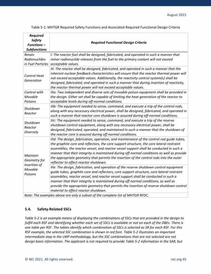
August 2021
© NEI 2021. All rights reserved. nei.org 45
Table 5-1: MHTGR Required Safety Functions and Associated Required Functional Design Criteria
Required Safety
Functions – Subfunctions
Required Functional Design Criteria
Retain Radionuclides in Fuel Particles
I: The reactor fuel shall be designed, fabricated, and operated in such a manner that minor radionuclide releases from the fuel to the primary coolant will not exceed acceptable values.
Control Heat Generation
III: The reactor shall be designed, fabricated, and operated in such a manner that the inherent nuclear feedback characteristics will ensure that the reactor thermal power will not exceed acceptable values. Additionally, the reactivity control system(s) shall be designed, fabricated, and operated in such a manner that during insertion of reactivity, the reactor thermal power will not exceed acceptable values.
Control with Movable Poisons
IIIa: Two independent and diverse sets of movable poison equipment shall be provided in the design. Either set shall be capable of limiting the heat generation of the reactor to acceptable levels during off-normal conditions.
Shutdown Reactor
IIIb: The equipment needed to sense, command, and execute a trip of the control rods, along with any necessary electrical power, shall be designed, fabricated, and operated in such a manner that reactor core shutdown is assured during off-normal conditions.
Shutdown Reactor Diversely
IIIc: The equipment needed to sense, command, and execute a trip of the reserve shutdown control equipment, along with any necessary electrical power, shall be designed, fabricated, operated, and maintained in such a manner that the shutdown of the reactor core is assured during off-normal conditions.
Maintain Geometry for Insertion of Movable Poisons
IIId: The design, fabrication, operation, and maintenance of the control rod guide tubes, the graphite core and reflectors, the core support structure, the core lateral restraint assemblies, the reactor vessel, and reactor vessel support shall be conducted in such a manner that their integrity is maintained during off-normal conditions as well as provide the appropriate geometry that permits the insertion of the control rods into the outer reflector to effect reactor shutdown. IIIe: The design, fabrication, and operation of the reserve shutdown control equipment guide tubes, graphite core and reflectors, core support structure, core lateral restraint assemblies, reactor vessel, and reactor vessel support shall be conducted in such a manner that their integrity is maintained during off-normal conditions, as well as provide the appropriate geometry that permits the insertion of reserve shutdown control material to effect reactor shutdown.
Note: The examples above are only a subset of the complete list of MHTGR RFDC.
5.4. Safety-Related SSCs
Table 5-2 is an example means of displaying the combinations of SSCs that are provided in the design to fulfill each RSF and identifying whether each set of SSCs is available or not on each of the DBEs. There is one table per RSF. The tables identify which combination of SSCs is selected as SR for each RSF. For this RSF example, the selected SSC combination is shown in red font. Table 5-2 illustrates an important intermediate step in the LMP methodology, but the SSC combinations that are not selected are not design basis information. The applicant is not required to provide Table 5-2 information in the SAR, but

August 2021
© NEI 2021. All rights reserved. nei.org 46
the information should be available in the plant records. Note that alternative ways to perform RSFs may be selected as an element of adequate Plant Capability DID and identified in Section 5.5 as NSRST SSCs.
Table 5-2: Example Table of Evaluation of SSCs for Core Heat Removal RSF
SSC Combinations Capable of Providing Core Heat Removal*
Available for DBE-1?
Available for DBE-2? … Available for
DBE-N? Selected as SR?
Reactor Heat Transport System Energy Conversion Area (ECA)
Yes No … No No
Reactor Shutdown Cooling System Shutdown Cooling Water System (SCWS)
No Yes … No No
Reactor Reactor Vessel (RV) Reactor Cavity Cooling System (RCCS)
Yes Yes … Yes Yes
Reactor Reactor Vessel Reactor Building (RB) passive heat sinks
Yes Yes … Yes No
*The entries in this column and the example selection as SR are examples from the MHTGR are found in Appendix A of the LMP SSC report.
The entries in Table 5-2 are an example developed for the MHTGR for a core heat removal RSF. Note that the selection of SR SSCs in this example includes SSCs needed to preserve the intrinsic characteristics of the reactor, such as power level, power density, and shape and selection of materials that enable the RSF to be fulfilled with the other identified SSCs.
A summary, as shown in Table 5-3, should be presented that lists all the SR SSCs, the AOOs, DBEs, and BDBEs, and the PRA Safety Functions responsible for preventing or mitigating each of these LBEs. Given there are multiple RSFs and that each RSF may require the use of multiple SSCs, there will, in general, be multiple SR SSCs. Operator actions that may be necessary to perform any of these functions should be identified through instrumentation and equipment needed to implement those operator actions.
Table 5-3: Example Table of Evaluation of SSCs for PRA Safety Functions
SR SSC LBE LBE Type
(AOO, DBE, or BDBE)
PRA Safety Function
SR SSC-1
LBE-11 ? PSF-11 LBE-12 ? PSF-12
… … … LBE-1n ? PSF-1n
Additional SR SSCs … … …
This table is organized by SR SSC in order to identify the capabilities of each SR SSC in preventing or mitigating each applicable LBE. These capabilities are used in Chapter 6 to support selection of special

August 2021
© NEI 2021. All rights reserved. nei.org 47
treatments. While SSCs are identified as SR for their role in mitigating DBEs and high consequence BDBEs, those SSCs may be used in the mitigation of other LBEs as well, and the table captures that information. The reliability and capability targets for SSCs address all LBEs, not just DBEs and high consequence BDBEs.
The LBE index numbers in the second column should be keyed to LBE indexes identified in Chapter 3 or alternatively spelled out. For each PRA Safety Function identified in the last column, the spelled-out function should be listed.
5.5. Non-Safety-Related with Special Treatments SSCs
This section presents the NSRST SSCs, the technical basis for the selection of NSRST SSCs, and identifies the PRA Safety Functions for the NSRST SSCs reflected in the LBEs in Chapter 3. Non-safety-related SSCs that are classified as NSRST because they perform risk-significant safety functions are identified in Section 5.5.1. Non-safety-related SSCs that are classified as NSRST because they perform safety functions deemed necessary for adequate DID are identified in Section 5.5.2.
5.5.1. Non-Safety-Related SSCs Performing Risk-Significant Functions
This section identifies the non-safety-related SSCs that perform risk-significant functions and meet the risk significance criteria for classification as NSRST. The risk significance classification is based on applying Steps 4B and 5B in Figure 4-1 in NEI 18-04 and the SSC risk significance criteria noted in Section 4.2.2 of NEI 18-04. Supporting documentation for details, calculations, etc., that were used to establish risk-significant SSC functions should be part of the plant records.
There are two types of risk significance criteria that come into play in NEI 18-04 for non-safety-related SSCs. The first criterion is based on identifying non-safety-related SSCs whose prevention or mitigation function is necessary to prevent one or more LBEs from exceeding the F-C Target. Any SSC functions that are risk significant based on this criterion should be identified in a table such as the example in Table 5-4. The purpose of the table is to identify the risk-significant SSCs, the PRA Safety Functions that are responsible for the classification, and the LBEs that would exceed the F-C Target if the PRA Safety Functions were not available. Operator actions that may be necessary to perform any of these functions should be identified in the description of the PRA Safety Functions, as well as the instrumentation and equipment needed to implement those operator actions.
Table 5-4: Example Table of SSCs Risk-Significant Due to F-C Curve
NSRST SSC LBE LBE Type (AOO, DBE, or BDBE)
PRA Safety Function
RS-NSRST SSC-1 LBE-RS-1 ? PSF-RS-1 RS-NSRST SSC-2 LBE-RS-2 ? PSF-RS-2 … … … RS-NSRST SSC-N LBE-RS-N ? PSF-RS-N

August 2021
© NEI 2021. All rights reserved. nei.org 48
The second risk significance criterion is based on whether the cumulative contribution of the LBEs in which an SSC safety function is failed exceeds 1% of the cumulative risk metrics used for evaluating the risk significance of LBEs. In this case, each risk-significant SSC is classified this way based on an accumulation of risk from multiple LBEs. These risk-significant SSCs should be identified in a table such as the following example (Table 5-5). The purpose is to identify the SSC classified as risk significant, the LBEs in which the SSC is failed, and the PRA Safety Function associated with that LBE. Operator actions that may be necessary to perform any of these functions should be identified in the description of the PRA Safety Functions, as well as the instrumentation and equipment needed to implement those operator actions.
Table 5-5: Example Table of SSCs Risk-Significant Due to Cumulative Risk
NSRST SSC LBE LBE Type (AOO, DBE, or BDBE)
PRA Safety Function
RS-NSRST-SSC-1
LBE-RS-11 ? PSF-RS-11 LBE-RS-12 ? PSF-RS-12
… … … LBE-RS-1n ? PSF-RS-1n
Additional RS-NSRST SSCs … … …
5.5.2. Non-Safety-Related SSCs Performing Safety Functions Necessary for Adequate DID
This section identifies the non-safety-related SSCs that are classified as NSRST because they perform safety functions deemed necessary for adequate DID. It should be noted that the SR SSCs identified in Section 5.4 are also key elements of the plant capability DID.
As with the risk-significant SSCs, the SSC classification for DID adequacy is normally tied to specific LBEs and should be summarized in a table such as Table 5-6. There may be some NSRST SSCs that were identified via the IDP that were not modeled in the PRA and not reflected explicitly in the LBEs due to limitations in the PRA or items screened out of the PRA.
Table 5-6: Example Table of SSCs Risk-Significant Due to DID
NSRST SSC LBE LBE Type
(AOO, DBE, or BDBE)
PRA Safety Function
DID-NSRST-SSC-1
LBE-DID-11 ? PSF-DID-11 LBE-DID-12 ? PSF-DID-12
… … … LBE-DID-1n ? PSF-DID-1n
Additional DID-NSRST SSCs … … …
Note: If an SSC is classified as NSRST but is not associated with a specific LBE, specify “N/A” under LBE and LBE type and identify the SSC function responsible for the NSRST classification under PRA Safety Function.

August 2021
© NEI 2021. All rights reserved. nei.org 49
5.6. Complementary Design Criteria
It is important to understand that Complementary Design Criteria (CDC), as they apply to NSRST SSCs, are somewhat, but not totally, analogous to PDC and how PDC apply to SR SSCs. PDC identified through TICAP are defined at the functional level and are based on the RFDC, as described in Section 5.3 of this guidance. PDC are “top-down” in that they correspond to RFDC and are independent of the actual SR SSCs that satisfy the RFDC. NEI 18-04 defines no direct counterpart for RFDC that flow down to NSRST SSCs. Section 5.5 describes how SSCs are identified as NSRST because they perform risk-significant functions or are identified as necessary for DID. CDC are not defined in NEI 18-04 but are useful in the description of the LMP-based affirmative safety case. Unlike PDC, CDC are identified as “bottom-up” in that they relate to specific NSRST SSCs, not higher-level functions. Accordingly, while PDC are defined at the functional level, CDC may also be defined at the functional level (related to the PRA Safety Functions that are satisfied by the NSRST SSCs), or CDC may be expressed more at an SSC level, directly linked to the NSRST SSCs themselves. The designer has latitude in choosing the approach, as long as the success criteria (discussed below) are clearly conveyed.
The CDC for NSRST SSCs are defined in terms of the success criteria for the PRA Safety Functions that are represented in the PRA model to prevent and mitigate the LBEs responsible for the safety classification. For example, a PRA Safety Function might be “Provide adequate heat removal from the reactor following initiating event X,” and the success criterion might be “Provide a coolant flow rate of Y kg/sec within Z minutes and maintain maximum fuel temperature less than ZZ for a specified set of LBEs.” SSCs are classified as NSRST either because the LMP risk significance criteria are met as identified in Section 5.5.1, or the criteria for adequate DID established by the IDP are met as identified in Section 5.5.2. The reliabilities and capabilities that are modeled in the PRA for the PRA Safety Functions associated with the SSC trigger the meeting of the risk significance or DID adequacy criteria for NSRST classification. These, in turn, serve to prevent and/or mitigate a specific set of LBEs. Hence the CDC for the NSRST SSCs are directly tied to the success criteria established in the PRA for the PRA Safety Functions responsible for the SSC classification as NSRST.
These should be presented in tabular form by listing the SSC, the PRA Safety Function(s) responsible for its safety classification as NSRST, and the design criteria that are necessary and sufficient to meet the PRA Safety Function (see example in Table 5-7). There may be more than one PRA Safety Function that is associated with the NSRST classification and more than one design criterion for each PRA Safety Function because the SSC may be represented in multiple LBEs.
Table 5-7: Example Table of NSRST SSCs with Corresponding CDC
NSRST SSC PRA Safety Function Complementary Design Criteria
NSRST SSC-1
PSF-11 Design criterion for PSF-11 PSF-12 Design criterion for PSF-12
… … PSF-1n Design criterion for PSF-1n
Additional NSRST SSCs … …

August 2021
© NEI 2021. All rights reserved. nei.org 50
Two-Step Licensing (CP Content)
For a CP application, Chapter 5 includes preliminary determination of the RSFs and RFDC (which are the PDC when using the LMP methodology), safety classification of SR and NSRST SSCs, and the Complementary Design Criteria leading to specific NSRST SSC design requirements. The LMP methodology for assessing safety functions, design criteria, and SSC safety classification, as described in Chapter 5 of the COL guidance, draws on results from the initial PRA. The PRA methodology described in Chapter 2 should be used in the preliminary determination of RSFs, determination of RFDC (PDC), CDC, and SSC safety classification. The structure and preliminary content of the Chapter 5 sections should follow the structure and content of the COL guidance Chapter 5 content. It should be noted that as the design evolves and construction continues, changes to the PRA modeling and results can be expected. Thus, the results in Chapter 5 are preliminary and can be expected to change as the design is finalized and the FSAR is developed for the OL application. At the CP stage, the use of performance-based bounding conditions for RFDC may be possible depending on the simplicity of the design and corresponding confidence in the PRA outputs.
Thus, the PSAR content for Chapter 5 should include functional decomposition of FSFs to RSFs, a preliminary set of RFDC (PDC) with performance-based criteria, and preliminary SSC classifications based on preliminary PRA results.
6. SAFETY-RELATED SSC CRITERIA AND CAPABILITIES
In Section 5.4, the SR SSCs were identified, and the bases for their classification were provided. Chapter 6 provides further detail on the criteria and capabilities of all SR SSCs in the LMP-based affirmative safety case, consistent with the NEI 18-04 methodology. This further detail includes SRDC, reliability and capability performance-based targets, and special treatment requirements to provide sufficient confidence that the performance-based targets intended in the design will be achieved in the construction of the plant and maintained throughout the licensed plant life. Chapter 6 also summarizes design requirements for non-safety-related SSCs that provide confidence that the non-safety-related SSCs will not adversely impact the ability of SR SSCs to support RSFs in the event that a hazard occurs at the DBHL. Note that these non-safety-related SSCs may be classified as NSRST or NST in the SSC safety classification process of LMP, but that classification process is based on their normal PRA Safety Functions, not on the passive function of protecting (or at least not impairing) SR SSCs as discussed in Section 6.1.3.
As discussed in NEI 18-04, an LMP-based affirmative safety case is both risk-informed and performance-based. The formulation of the SRDC should be quantitatively framed so that the successful performance of the SSC may be confirmed via calculation or monitoring to facilitate the performance-based attribute of the safety case, as discussed in Section 6.1. Additional performance-based elements are incorporated in the selection of SSC reliability targets (Section 6.2) that are used to establish special treatment requirements (Section 6.3).
This guidance assumes that the applicant followed the NEI 18-04 methodology for the establishment of SR SSC criteria and capabilities. If the applicant did not use parts of the methodology or used an alternative method, the following statement should be added:
The following deviations from the approved methodology were taken.
August 2021
© NEI 2021. All rights reserved. nei.org 51
The applicant should go on to list each deviation, describe any alternative method, and provide justification for the approach employed.
6.1. Design Requirements for Safety-Related SSCs
This section describes the outputs of NEI 18-04 Section 4.1, Task 7. Details of the analyses and justifications for the development of SRDC should be in the plant records.
6.1.1. Design Basis Hazard Levels
One general category of design requirements flows from the need to protect the SR SSCs in the performance of their RSF from design basis hazards. Each hazard is characterized by a DBHL (e.g., wind speed). This is discussed in NEI 18-04 Section 3.2.2, Task 6, and the following text from the first page of Section 4 in NEI 18-04.
It is noted that there will be design requirements to protect all SR SSCs from any adverse impacts of any DBEHLs. This may lead to design requirements to prevent any adverse impacts from the failure of an SSC classified as NST or NSRST that could otherwise prevent an SR SSC from performing its RSFs.
Note that this guidance document uses the nomenclature of DBHL instead of the DBEHL term from NEI 18-04. While not discussed comprehensively in NEI 18-04, there is a need to consider not only hazards external to the plant (traditional external events) but also hazards external to the SSCs performing PRA Safety Functions – i.e., internal plant hazards such as internal fires, floods, turbine missiles, and high energy line breaks. To clarify the original intent of NEI 18-04 to address both categories of hazards, this guidance document uses the DBHL term instead of DBEHL.
It is important to note that the DBHLs go beyond environmental hazards originating external to the plant. The scope of the DBHLs includes external hazards such as seismic events, wind including tornados and wind-generated missiles, external flooding, hazards from external facilities, and internal plant hazards such as internal fires, internal floods, high energy line breaks, and internally generated missiles. These internal plant hazards are frequently described as “area events.” Guidance on the scope of hazards may be found in Chapter 3 of the Standard Review Plan (NUREG-0800). The concept is to ensure that hazards with a frequency down to 10-4/plant-year are identified so that design requirements identified in Section 5.4 for the SR SSCs to protect them against any DBHL can be specified. Each DBHL may impact one or more reactors as well as non-reactor radioactive sources.
NEI 18-04 provides the option of selecting DBHLs either deterministically or probabilistically. These levels are design requirements on the plant capabilities to enable the SR SSCs to perform their RSFs. In either case, the hazards are addressed in the PRA and result in the identification of new LBEs. Note that the DBHLs, whether selected deterministically or probabilistically, are one of the inputs to the analysis of hazards in the PRA. When the hazards are addressed in the PRA, the response of the plant to the full frequency spectrum of the hazards will be considered and result in LBEs initiated by hazards that may appear in the AOO, DBE, and BDBE regions. DBEs caused by a hazard would then be mapped to a corresponding DBA in which only SR SSCs would be credited with performing each RSF. DBHLs may be defined either before or after internal and external hazards are incorporated into the PRA. In either case, to be consistent with the LMP methodology, there must be sufficient capability in the SR SSCs to enable the performance of their RSFs following the occurrence of a hazard at the DBHL.

August 2021
© NEI 2021. All rights reserved. nei.org 52
NEI 18-04 identifies two alternative approaches for the selection of DBHLs. One is to use the existing criteria in Chapter 3 of the Standard Review Plan, in which case the selection is made deterministically. The second alternative is to derive the DBHLs based on a probabilistic hazard analysis subject to review by the NRC staff. For each hazard, the method used should be clearly identified in the SAR. For hazard levels derived probabilistically, the technical requirements for probabilistic hazard analysis in the non-LWR PRA standard should be used and referenced. The PRA documentation would then provide the technical basis for the derivation of those DBHLs.
Chapter 3 of current LWR SARs provides extensive detail on the translation of DBHLs to loads on SSCs, evaluation of those loads, and related design analyses. The calculations are not specific to an LMP-based affirmative safety case, and TICAP is not providing guidance on presenting the results of such calculations. The guidance will be provided by the NRC in ARCAP. Applicants can also refer to Chapter 3 of the Standard Review Plan (SRP)23 for guidance in this area. For an advanced non-LWR SAR, this material may be included in Chapter 2 or in reports external to, and appropriately referenced in, the SAR. The scope and level of detail of these calculations are design- and site-specific, but the information can be quite voluminous for LWRs. This area may present an opportunity to reduce the amount of information included directly in an advanced non-LWR SAR.
The DBHLs should be summarized in this section. A tabular form such as Table 6-1 is recommended. If the DBHLs are selected probabilistically from the PRA, the basis for the DBHL resides in the PRA documentation in plant records. If the DBHLs are selected deterministically, the basis is addressed by ARCAP and documented in SAR Chapter 2.
Table 6-1: Example Table of Design Basis External Hazard Levels
Hazard Design External Hazard Level
Seismic Events
Specify design basis earthquake parameters such as safe shutdown earthquake peak ground acceleration, design response spectra, damping values, time histories, etc. Note that there are no requirements for specifying an operating basis earthquake as part of an LMP-based affirmative safety case.
Tornadoes Specify design basis wind loadings and design parameters.
External Flood Specify design basis flood levels and design parameters.
Internal Fires Identify fire areas where SR SSCs are located and fires may occur and the limiting fire conditions that may impact any SR SSCs at frequencies of 1×10⁻⁴/plant-year or above.
Internal Flood Identify flood areas where SR SSCs are located and flood may occur and the limiting flood conditions that may impact any SR SSCs at frequencies of 1×10⁻⁴/plant-year or above.
High energy line breaks Identify areas where SR SSCs are located and a high energy line break may occur and the limiting HELB conditions that may impact any SR SSCs at frequencies of 1×10⁻⁴/plant-year or above.
23 NUREG-0800, Standard Review Plan for the Review of Safety Analyses Reports for Nuclear Power Plants: LWR Edition, U.S. Nuclear Regulatory Commission.

August 2021
© NEI 2021. All rights reserved. nei.org 53
Hazard Design External Hazard Level Other internal and external hazards that SR SSCs are protected against
Identify hazards and affected areas and specify appropriate hazard severity and design parameters.
Two-Step Licensing (CP Content)
The CP application content for Section 6.1.1 addressing DBHLs should be as complete as possible based on the site characterization required in 10 CFR 50.34(a). The external and internal hazard levels are inputs to the PRA and to SSC design. Thus, including details on this information in the PSAR will support demonstrating the viability of the design and developing the FSAR consistent with Chapter 6 of the COL guidance.
Design Certification
Section 6.1.1 should describe the bounding site characterizations considered in the definition of the DBHLs. To the extent that the hazard characterizations impact internal hazard levels, those impacts should be identified and included in the PRA.
PRA requirements for the selection and documentation of the bounding site characteristics (i.e., the site parameter envelope) used in the hazard PRAs are found in the Advanced non-LWR PRA Standard, ASME/ANS RA-S-1.4-2021.
6.1.2. Summary of SRDC
In the text for Task 7 of Figure 4-1 in NEI-18-04, it is stated:
“The RFDC, SRDC, the reliability and capability targets for SR and NSRST SSCs, and special treatment requirements for SR and NSRST SSCs define safety-significant aspects of the descriptions of SSCs that should be included in safety analysis reports.”
The RFDC are identified in Section 5.3, and the RSFs that they support are identified in Section 5.2. For each of the RFDC, this section should identify a set of SRDC appropriate to the SR SSCs selected to perform the RSFs. These SRDC exclude Special Treatment Requirements, which are separately covered in Section 6.2. The RFDC, which are expressed in the form of functions and involve collections of SSCs and intrinsic capabilities of the plant, may be viewed as a bridge between the RSFs and the SRDC. The SRDC is more detailed requirements for specific SR SSCs in the performance of the RSF functions in specific DBAs. Examples of SRDC that were developed for the MHTGR are found in Appendix A of the LMP SSC report. 22
For the SRDC, the following information is presented in tabular form, as shown in Table 6-2:
• The first column contains the SSC names.
• The second column provides brief SSC functional descriptions.

August 2021
© NEI 2021. All rights reserved. nei.org 54
• The third column lists the RFDC that the SR SSCs support. Most likely, there is only one RFDC associated with each SR SSC, but if there is more than one, all should be listed. Note that the links from the SR SSCs back to the LBEs that define the RSFs are provided in Chapter 5.
• The fourth column lists the SRDC. There may be more than one SRDC for each SR SSC.
Table 6-2: Example Table of Safety-Related Design Criteria for SSCs
SR SSC Functional Description RFDC SRDC
SR SSC1 Functional Description of SR SSC1 RFDCx
SRDC11 SRDC12
… SRDC1n
Additional SR SSCs … … …
6.1.3. Summary of DBHL-Related Requirements for Non-Safety-Related SSCs
Chapter 6 also identifies DBHL-related design requirements for non-safety-related SSCs. These design requirements are to support the special safety functions that are applied to the non-safety-related SSCs to prevent adverse impacts on the ability of the SR SSCs to perform the RSFs. An example is the requirement for anchorage to prevent a non-safety-related SSC from failing in such a manner that it would impact an SR SSC and cause it to fail to perform its RSF.
It is important to note that the non-safety-related SSCs covered in these requirements are not for the SSC functions that they normally perform but for the special function of preventing any adverse impact on the capability of any SR SSC in the performance of the RSF. The DBHL includes external hazards such as seismic events as well as internal plant hazards such as internal fires and floods, turbine missiles, and high energy line breaks. When a non-safety-related SSC is required to protect the SR SSCs in their ability to perform their RSFs, such non-safety-related SSCs are not necessarily NSRST. The NSRST classifications are based on the PRA Safety Functions these SSCs perform to prevent or mitigate event sequences and not functions that are focused on protecting the SR SSCs.
For the non-safety-related SSCs that have design requirements to protect the SR SSCs in the performance of the RSFs in response to a DBHL, the following information in tabular form should be provided, as illustrated in the example below (Table 6-3).
• The first column identifies the non-safety-related SSCs.
• The second column lists the RSFs and SR SSCs that are protected.
• The third column identifies the DBHLs that are associated with these requirements.
• The fourth column identifies the specific design requirement for the function to protect the SR SSCs for each of the DBHLs. Note that this function is different from the PRA Safety Functions for the same non-safety-related SSCs.

August 2021
© NEI 2021. All rights reserved. nei.org 55
Table 6-3: Example Table of Non-Safety-Related SSCs Protecting SR SSCs from DBHLs
Non-Safety-Related SSC
Protected RSF and SR SSC DBHL Non-Safety-Related SSC
Design Requirement
Non-safety-related SSC-1 RSF/SR SSCx
DBHL-1 Non-safety-related DC-11
DBHL-2 Non-safety-related DC-12
… …
DBHL-n Non-safety-related DC-n
Additional non-safety-related SSCs … … …
6.2. Reliability and Capability Targets for SR SSCs
In the NEI 18-04 methodology, the main purpose of establishing reliability and capability targets is to identify special treatment requirements. In accordance with NEI 18-04 Section 4.1, the targets are formally documented at the SSC level. Whether it is done at the system level or for components of a system is a detail that is left to the applicant.
The term “reliability” as used informally in NEI 18-04 refers to the reliability performance metrics involved in the estimation of event sequence frequencies. Reliability metrics include unavailability, unreliability, event occurrences, time out-of-service, fraction of time in an operating state, etc., as needed to evaluate safety function failure probabilities in the PRA. Reliability is not observable but rather is calculated based on observed performance measures and available generic evidence.
The term “capability” is a performance measure used to establish the successful prevention or mitigation of LBEs. Capability is linked to the success criterion used to quantify the failure probability in the PRA. An SSC involved in mitigating two separate LBEs could have different capability targets for each LBE.
Reliability and capability targets can be established at different levels.
• Plant level: numerical targets for controlling the frequencies, consequences, and risk significance of the LBEs
• Functional level: numerical targets for controlling the reliabilities and capabilities of safety functions across multiple LBEs
• SSC level: numerical targets for controlling the reliabilities and capabilities of individual SSCs (or humans) in the performance of safety function
Plant level targets are addressed as part of Chapter 3 and require no additional documentation. Applicants may choose to document functional level targets in Chapter 5, but that is not a requirement.
SSC level targets should be addressed in Section 6.2. Except for the simplest of designs, reliability and capability targets at the SSC level will be quite voluminous. The applicant may choose to include the
August 2021
© NEI 2021. All rights reserved. nei.org 56
information directly in Section 6.2, but due to the large quantity of information, it is expected the SSC-level reliability and capability targets will more often be maintained by plant programs in plant records that are IBR. In those records, each SSC should specify the reliability and capability targets as well as the LBE(s) that the SSC prevents or mitigates.
In addition to the target information or associated reference, Section 6.2 should specify the plant program(s) used to maintain the reliability and capability targets. Information on the program(s) should be provided in Chapter 8.
6.3. Special Treatment Requirements for SR SSCs
NEI 18-04 adopted the definition of special treatment that is provided in RG 1.201, “Guidelines for Categorizing Structures, Systems, and Components in Nuclear Power Plants According to Their Safety Significance,”24 which was developed for implementing 10 CFR 50.69.
“…special treatment refers to those requirements that provide increased assurance beyond normal industrial practices that structures, systems, and components (SSCs) perform their design-basis functions.”
Anything that is done beyond procuring commercial-grade equipment to provide increased assurance in the capability and reliability of the SSC falls into the category of special treatment. Hence, all the design requirements provided in Section 6.1 are part of the special treatment. This section identifies the additional special treatments that are applied to SR SSCs. Candidate special treatments for consideration in the IDP are identified in Table 4-1 of NEI 18-04 and are applied to individual SSCs on a case by case basis. Special treatments include monitoring programs to track the performance of the SSCs against the targets and corrective actions when performance targets are exceeded.
As noted in Section 4.4.5 of NEI 18-04, the selection of special treatments for all safety-significant SSCs (SR and NSRST) is informed by a set of targets for the reliability and availability of the SSCs in their prevention functions as well as targets for the capability of the SSCs in the performance of their mitigation functions. These specific targets are addressed in Section 6.2. The focus of this section in the application is to produce the resulting special treatment requirements.
For the selected special treatments, the license application should identify the treatments in the license application with details available for NRC audits in the license application.
The special treatments should be summarized in tabular form (see Table 6-4) by listing each SR SSC, providing a brief performance-based functional description, and identifying which special treatment has been selected for each SR SSC.
Some plant designs may involve first-of-a-kind testing for SR SSCs. To the extent those first-of-a-kind tests have not been completed by the time of the application, they may be included as special treatments.
24 Regulatory Guide 1.201, “Guidelines for Categorizing Structures, Systems, and Components in Nuclear Power Plants According to Their Safety Significance,” U.S. Nuclear Regulatory Commission, May 2006 (ML061090627).

August 2021
© NEI 2021. All rights reserved. nei.org 57
Table 6-4: Example Table of SR SSC Special Treatments
SR SSC Functional Description SR SSC Special Treatments
SR SSC-1
Short SSC functional description for SR SSC1
SR SSC-1 Special Treatment No. 1 SR SSC-1 Special Treatment No. 2
… SR SSC-1 Special Treatment No. n
Additional SR SSCs … …
6.4. Descriptions for SR SSCs
This section provides descriptions for SR SSCs. These descriptions include the specific design features for SR SSCs that are responsible for meeting the SRDC and fulfilling their RSFs to mitigate the DBAs. This description should include features that demonstrate system capability and reliability for both prevention and mitigation of LBEs, as applicable.
6.4.1. Description for SR SSC-1
This description should include:
• Simplified schematic diagram
• Narrative design descriptions that address the design aspects relevant to the performance of the RSFs, including:
o The SSC purpose in the context of supporting the RSFs
o The specific SSC function in the context of supporting the RSFs
o SSC materials and construction
o SSC location and environmental conditions during normal operation and in the performance of the RSFs during LBEs
o Key design features relevant to the performance of RSFs
o Seismic and industry (e.g., ASME and IEEE) code classifications and the design codes applicable to the SR SSC
o A description of all modes of SSC operation, including an account of the performance modes of SSC operation relevant to the RSFs
o Identification of operator actions needed to implement the RSFs
o Controls and displays needed to accomplish RSFs

August 2021
© NEI 2021. All rights reserved. nei.org 58
o Logic circuits and interlocks needed to support RSFs
o Electric power, support systems, and interface requirements needed to support the RSFs
o Equipment to be qualified for harsh environments as needed to meet SR SSC special treatment requirements defined in Section 6.2
o Brief summaries of first-of-a-kind special treatment tests to be performed (if any)
o Cross-reference to Chapter 8 where applicable programs to implement the special treatments are identified
6.4.2, 6.4.3, et al.: Descriptions of the remainder of the SR SSCs are provided.
Two-Step Licensing (CP Content)
For a CP application, the classification of SSCs from Chapter 5 is preliminary. However, the approach and methodologies to be used in developing the FSAR Chapter 6 content should be clearly described. The description should include any consensus codes and standards used or expected to be used in the design of SR SSCs. The descriptions for SR SSCs should be provided at a functional level and should identify the performance-based requirements needed for individual major components. Any safety-related first-of-a-kind components should be identified, as should plans for component performance validation and acceptance criteria. The guidance for other SSC description content in Chapter 6 should be tailored to the information available at the CP stage. The preliminary results from Chapter 5 should be used to frame the development of SRDC and special treatment requirements for SR SSCs. The content of Chapter 6 should use the tabular format provided in Chapter 6 of the COL guidance.
7. NSRST SSC CRITERIA AND CAPABILITIES
In Section 5.5, the NSRST SSCs were identified. Chapter 7 provides further detail on the role of each NSRST SSC in the LMP-based affirmative safety case, consistent with the NEI 18-04 methodology. Complementary design criteria for NSRST SSCs are covered in Section 5.5.4. The remaining criteria and capabilities for NSRST SSCs include reliability and capability performance targets and special treatment requirements to provide sufficient confidence that the performance targets will be maintained throughout the life of the licensed plant. Anything beyond procuring commercial-grade equipment that is done to provide increased assurance in the capability and reliability of the SSC falls into the category of special treatment.
As noted in Section 4.4.5 of NEI 18-04, the selection of special treatments for all safety-significant SSCs (SR and NSRST) are informed by a set of targets for the reliability and availability of the SSCs in their prevention functions as well as targets for the capability of the SSCs in the performance of their mitigation functions. These specific targets are addressed in Section 7.1, and the special treatments themselves are covered in Section 7.2.
This guidance assumes that the applicant followed the NEI 18-04 methodology for the establishment of SR SSC criteria and capabilities. If the applicant did not use parts of the methodology or used an alternative method, the following statement should be added:
The following deviations from the approved methodology were taken.

August 2021
© NEI 2021. All rights reserved. nei.org 59
The applicant should go on to list each deviation, describe any alternative method, and provide justification for the approach employed.
7.1. Reliability and Capability Targets for NSRST SSCs
Background information for SR SSCs in Section 6.2 is applicable to NSRST SSCs as well and is not repeated here. The treatment of targets is the same for NSRST and SR SSCs.
SSC level targets should be addressed in Section 7.1. Except for the simplest of designs, reliability and capability targets at the SSC level will be quite voluminous. The applicant may choose to include the information directly in Section 7.1, but due to the large quantity of information, it is expected the SSC-level reliability and capability targets will more often be maintained by plant programs in plant records that are IBR. In those records, each SSC should specify the reliability and capability targets as well as the LBE(s) that the SSC prevents or mitigates.
In addition to the target information or associated reference, Section 7.1 should specify the plant program(s) used to maintain the reliability and capability targets. Information on the program(s) should be provided in Chapter 8.
7.2. Special Treatment Requirements for NSRST SSCs
This section documents the special treatment requirements for NSRST SSCs.
NEI 18-04 adopted the definition of special treatment provided in RG 1.201, “Guidelines for Categorizing Structures, Systems, and Components in Nuclear Power Plants According to Their Safety Significance,” 25 which was developed for implementing 10 CFR 50.69:
“…special treatment refers to those requirements that provide increased assurance beyond normal industrial practices that structures, systems, and components (SSCs) perform their design-basis functions.”
Anything that is done beyond procuring commercial-grade equipment to provide increased assurance in the capability and reliability of SSCs falls into the category of special treatment. Section 6.1 identified non-safety-related SSC design requirements associated with protecting SR SSCs from design basis hazards. Hence, if a non-safety-related SSC identified in Section 6.1.3 is also an NSRST SSC, then all the design requirements provided in Section 6.1 are part of the NSRST’s special treatment. This section identifies the additional special treatments that are applied to NSRST SSCs.
For the selected special treatments, the license application should identify the treatments in the SAR with details available in the plant records.
The special treatments should be summarized in tabular form (see Table 7-1) by listing each NSRST SSC, providing a brief functional description, and identifying which special treatment has been selected for each NSRST SSC.
25 Regulatory Guide 1.201, “Guidelines for Categorizing Structures, Systems, and Components in Nuclear Power Plants According to Their Safety Significance,” U.S. Nuclear Regulatory Commission, May 2006 (ML061090627).

August 2021
© NEI 2021. All rights reserved. nei.org 60
Some plant designs may involve first-of-a-kind testing for NSRST SSCs. To the extent those first-of-a-kind tests have not been completed by the time of the application, they may be included as special treatments.
Table 7-1: Example Table of NSRST SSC Special Treatments
NSRST SSC Functional Description NSRST SSC Special Treatments
NSRST SSC-1 Short SSC functional description for NSRST SSC1
NSRST SSC-1 Special Treatment No. 1 NSRST SSC-1 Special Treatment No. 2 … NSRST SSC-1 Special Treatment No. n
Additional NSRST SSCs … …
7.3. System Descriptions for NSRST SSCs
This section provides descriptions for NSRST SSCs. These descriptions include the specific design features for NSRST SSCs that are responsible for meeting their safety-significant functions identified in the LBEs responsible for the classification as NSRST. This description should include features that demonstrate SSC capability and reliability for both prevention and mitigation of LBEs, as applicable. It is expected that these SSC descriptions will be less detailed than those provided for SR SSCs in Section 6.3, even though the list of covered items is similar.
The bulleted list in 7.3.1 is very similar to the list in 6.4.1 for SR SSCs. The NSRST SSC information does not need to be as comprehensive and detailed as the SR SSC information.
7.3.1. Description for NSRST SSC-1
This description should include:
• A simplified schematic diagram
• Narrative design descriptions that address the design aspects relevant to the performance of the safety-significant functions including, as applicable:
o The SSC purpose in the context of supporting the safety-significant functions
o Significant functional performance-based characteristics in performing safety-significant functions
o SSC location
o Key design features relevant to the performance of safety-significant functions

August 2021
© NEI 2021. All rights reserved. nei.org 61
o Seismic and industry (ASME, IEEE, etc.) code classifications and the design codes applicable to the NSRST SSC
o Description of all modes of SSC operation, including a description of the performance modes of SSC operation relevant to the safety-significant functions
o Identification of any operator actions needed to implement safety-significant functions
o Controls and displays needed to support safety-significant functions
o Logic circuits and interlocks needed to support safety-significant functions
o Electric power, support systems, and interface requirements needed to support the safety-significant functions
o Equipment to be qualified for harsh environments as needed to meet NSRST SSC special treatment requirements defined in Section 7.2
o Brief summaries of first-of-a-kind special treatment tests to be performed (if any)
o Cross-reference to Chapter 8 where applicable programs to implement the special treatments are identified
7.3.2, 7.3.3, et al.: Descriptions of the remainder of the NSRST SSCs are provided.
Two-Step Licensing (CP Content)
For a CP application, Chapter 7 content addressing NSRST SSCs should follow the approach used in Chapter 6 for SR SSCs. A preliminary list of NSRST SSCs should be populated to the extent the DID evaluation has been performed and described in Chapter 4 and should use the tabular format provided in Chapter 7 of the COL guidance. Descriptions for NSRST SSCs as described in Chapter 7 should be developed to identify safety-significant functions to be provided by those SSCs.
8. PLANT PROGRAMS
The guidance in this chapter is not intended to address all plant programs. It focuses on those that play a substantive role in the LMP-based affirmative safety case. For example, nuclear power reactors require a radiological protection program for plant workers in order to ensure compliance with occupational dose regulations in 10 CFR Part 20. However, the radiological protection program for plant workers is unlikely to be a component of the safety case, which is based on protection of the public from radiological hazards.
The chapter should provide an overview of plant programs relied upon to support the LMP-related affirmative safety case programs, addressing the purpose, scope, and performance objectives as well as applicability to SR SSCs, NSRST SSCs, or operations activities. The intent is not to provide a detailed description of how each program works. Such details will inevitably evolve over time and are fully described in plant records. However, the performance objectives of the program should be provided to enable an understanding of the objectives of the program relative to the targets or special treatments

August 2021
© NEI 2021. All rights reserved. nei.org 62
identified for SR SSCs and NSRST SSCs. This information should be included in the SAR or in documents that are incorporated by reference (IBR).
The set of programs in Chapter 8 includes those used for special treatments for SR or NSRST SSCs as described in Chapters 6 and 7, respectively, that provide reasonable assurance that (i) reliability and performance targets are achieved throughout the plant lifetime and (ii) safety-significant uncertainties are effectively addressed as part of DID. In addition to programs supporting special treatments, this chapter should also identify and provide an overview of the program or programs that document SSC reliability and capability targets, as described in Sections 6.2 and 7.1. The discussion of plant programs should address the different plant lifetime phases, i.e., design, construction, testing, and operations, as applicable.
Examples of possible program topics are provided below. The actual program topics are determined by the special treatments documented in Chapters 6 and 7. Not all of the examples may be required for a given application, and additional program topics not listed below may be required.
• Quality assurance programs (design, construction, operations)
• Startup testing
• In-service testing
• In-service inspection
• Equipment qualification
• Performance monitoring
• Reliability assurance
The applicant should provide the following information in this chapter of the SAR:
• Program topic and summary scope description
• SSC class applicability (SR, NSRST, or NST)
• Controlling program document including title, document number, revision number, and date. The expectation is that each program supporting the LMP-based affirmative safety case will have an associated controlling document maintained by the design authority or licensee. This document could be a topical report that has been reviewed and approved by NRC or an internal document.
• Standard industry program references, if any, used as a basis for a program, e.g., standards or Nuclear Energy Institute guidance documents (For each reference, it should be noted whether it is incorporated by reference [IBR] or provided for information [Ref] as described in Section 1.4.)
• In the event of any significant deviations from an IBR standard industry program, identification of the deviation and associated explanation

August 2021
© NEI 2021. All rights reserved. nei.org 63
• Whether via an IBR standard industry program or an applicant-specific IBR program reference, the program information should address purpose, scope, controls, and applicable regulations and regulatory guidance.
The applicant has the option of providing the information in this chapter in a tabular format or in text. For the former, an example table with entries for programs is provided in Table 8-1. (Note that the example entries are meant to be illustrative, representative content for a specific program and not the comprehensive program description.)
Table 8-1: Example Table of Special Treatment Programs
Program Topics / Objectives SSC
Applicability Program References and Deviations IBR Ref
SR NSRST NST Quality Assurance (QA) Program
The QA Program comprises the planned and systematic activities implemented to demonstrate that SSCs and activities will fulfill their requirements. It provides assurance that the actual plant configuration is consistent with the capabilities modeled in the licensing basis event analyses. Depending on the requirements associated with the specific SSC, the full range of QA controls may be applied, or a subset thereof.
√ √ √
Insert controlling program document information (e.g., XYZ123, Quality Assurance Topical Report).
√
ASME NQA-1, “Quality Assurance Requirements for Nuclear Facility Applications,” 2019.
√
Deviation: The Quality Assurance Program is based on NQA-1, but a graded approach is applied as described in the Quality Assurance Topical Report.
Reliability Assurance Program
The plant reliability assurance program controls the reliability and availability targets of SR SSCs and NSRST SSCs consistent with the PRA.
√ √
Insert controlling program document information (e.g., ABC789, Reliability Assurance Program).
√
NUREG-0800 Section 17.4, Reliability Assurance Program Rev 0, 2007.
√
ASME Section XI-Rules for Inservice Inspection of Nuclear Power Plant Components, Division 2, Requirements for Reliability and Integrity Management (RIM) Programs for Nuclear Power Plants, 2019.
√
Deviation: NUREG-0800 Section 17.4 applies to SR SSCs only as described in the Reliability Assurance Program document.
Maintenance Program √ √ √ Insert controlling program document information (e.g., √

August 2021
© NEI 2021. All rights reserved. nei.org 64
Program Topics / Objectives SSC
Applicability Program References and Deviations IBR Ref
SR NSRST NST The plant maintenance controls the performance of maintenance activities in the plant. It provides assurance that the actual plant configuration is consistent with the capabilities modeled in the licensing basis event analyses.
LMN456-0, Plant Maintenance Program).
NUMARC 93-01, “Industry Guideline for Monitoring the Effectiveness of Maintenance at Nuclear Power Plants,” Revision 4F, Nuclear Energy Institute, April 2018.
√
Regulatory Guide 1.160, Revision 4, “Monitoring the Effectiveness of Maintenance at Nuclear Power Plants,” August 2018.
√
NEI 07-02A “Generic FSAR Template Guidance for Maintenance Rule Program Description for Plants Licensed Under 10 CFR Part 52,” (Rev 0) March 2008
√
Deviations: None. √
If the table approach is used, the rest of the guidance in Chapter 8 is not applicable. If a text-based approach is used instead of a table, the applicant would be expected to use a section for each program topic. An example is provided below.
8.1. Maintenance Program
The plant maintenance program controls the performance of maintenance activities in the plant. It provides assurance that the actual plant configuration is consistent with the capabilities modeled in the licensing basis event analyses. The program applies to SR, NSRST, and NST SSCs. The program is administered in accordance with applicant document LMN456-0, “Plant Maintenance Program,” which is IBR.
NUMARC 93-01, “Industry Guideline for Monitoring the Effectiveness of Maintenance at Nuclear Power Plants,”26 (Ref) documents acceptable practices for implementation of the Maintenance Rule (10 CFR 50.65). NRC Regulatory Guide 1.160, “Monitoring the Effectiveness of Maintenance at Nuclear Power Plants”27 (Ref) endorses NUMARC 93-01 and provides additional guidance. NEI 07-02A, “Generic FSAR Template Guidance for Maintenance Rule Program Description for Plants Licensed under 10 CFR Part
26 NUMARC 93-01, “Industry Guideline for Monitoring the Effectiveness of Maintenance at Nuclear Power Plants,” Rev 4F, Nuclear Energy Institute, April 2018. 27 Regulatory Guide 1.160, “Monitoring the Effectiveness of Maintenance at Nuclear Power Plants,” Rev 4, U.S. Nuclear Regulatory Commission, August 2018.

August 2021
© NEI 2021. All rights reserved. nei.org 65
52,”28 (Ref) provides additional guidance. The guidance documents were developed for light water reactors and therefore informed but did not determine the maintenance program for the [applicant reactor name] reactor.
There are no deviations from the referenced documents.
8.2. Other Programs
Other programs are described in Sections 8.2, 8.3, etc.
Two-Step Licensing (CP Content)
The PSAR should contain complete identification of design, manufacturing, and construction programs to be used prior to the issuance of the OL, including references to standardized industry programs that are used as frameworks or templates for these programs. The PSAR should contain general descriptions of the operational programs that may be incorporated in the FSAR to support the LMP-based affirmative safety case, with the understanding that such descriptions will be updated at the OL stage, consistent with the COL guidance provided above.
28 NEI 07-02A, “Generic FSAR Template Guidance for Maintenance Rule Program Description for Plants Licensed Under 10 CFR Part 52,” Rev 0, Nuclear Energy Institute, March 2008.

August 2021
© NEI 2021. All rights reserved. nei.org 66
SUMMARY
The guidance contained in Section C of this report is one acceptable means of providing content for the portion of an advanced reactor SAR related to the application of the RIPB LMP-based affirmative safety case methodology described in NEI 18-04.
The Section C guidance applies to a COL under 10 CFR Part 52, “Licenses, Certifications, and Approvals for Nuclear Power Plants.” The guidance further assumes that the applicant is not referencing an existing Design Certification. Section C also provides modifications to the baseline COL guidance for two alternative licensing approaches:
• Two-step licensing (CP/OL)—The applicant first applies for and obtains a CP under 10 CFR Part 50, “Domestic Licensing of Production and Utilization Facilities,” and subsequently applies for and obtains an OL also under 10 CFR Part 50.
• Design certification—The applicant is a reactor vendor that applies for a standard design certification under 10 CFR Part 52, Subpart B. It does not contain site-specific information. A future applicant would reference the design certification along with site-specific and owner-specific information as part of a COL application.

August 2021
© NEI 2021. All rights reserved. nei.org A-1
APPENDIX A. GLOSSARY OF TERMS
Term Acronym Definition Source
Anticipated Operational Occurrence
AOO
Anticipated event sequences expected to occur one or more times during the life of a nuclear power plant, which may include one or more reactors. Event sequences with mean29 frequencies of 1×10⁻²/plant-year and greater are classified as AOOs. AOOs take into account the expected response of all SSCs within the plant, regardless of safety classification.
NEI 18-04 Modified for TICAP
Beyond Design Basis Event BDBE
Rare event sequences that are not expected to occur in the life of a nuclear power plant, which may include one or more reactors, but are less likely than a DBE. Event sequences with mean29 frequencies of 5×10⁻⁷/plant-year to 1×10⁻⁴/plant -year are classified as BDBEs. BDBEs take into account the expected response of all SSCs within the plant regardless of safety classification.
NEI 18-04 Modified for TICAP
Complementary Design Criteria CDC
Design criteria for NSRST SSC that are necessary to satisfy the PRA Safety Function(s) associated with the SSC. The CDC may be defined at a functional level, or more specifically addressed to the NSRST SSC specific function(s). The CDC for the NSRST SSC are directly tied to the success criteria established in the PRA for the PRA Safety Function(s) responsible for the classification of the SSC as NSRST.
TICAP
Defense-in-Depth DID
An approach to designing and operating nuclear facilities that prevents and mitigates accidents that release radiation or hazardous materials. The key is creating multiple independent and redundant layers of defense to compensate for potential human and mechanical failures so that no single layer, no matter how robust, is exclusively relied upon. Defense-in-depth includes the use of access controls, physical barriers, redundant and diverse key safety functions, and emergency response measures.
NRC Glossary
Design Basis Accident DBA
Postulated accidents that are used to set design criteria and performance objectives for the design of SR SSCs. DBAs are derived from DBEs based on the capabilities and reliabilities of SR SSCs needed to mitigate and prevent accidents, respectively. DBAs are derived from the DBEs by prescriptively assuming that only SR SSCs classified are available to mitigate postulated accident consequences to within the 10 CFR 50.34 dose limits.
NEI 18-04
29 The classification of AOOs, DBEs, and BDBEs is based on the mean frequencies of the underlying uncertainty distributions. When the uncertainty band on the frequency defined by the 95th and 5th percentiles of the distribution straddle one of the frequency boundaries, the LBEs are evaluated on each side of the boundary, per NEI 18-04. For example, if a BDBE has a 95th percentile estimate above 1×10⁻⁴ per plant year, it is treated as a DBE for the purposes of defining the RSFs and defining the DBAs.
August 2021
© NEI 2021. All rights reserved. nei.org A-2
Term Acronym Definition Source
Design Basis Event DBE
Infrequent event sequences that are not expected to occur in the life of a nuclear power plant, which may include one or more reactors, but are less likely than AOOs. Event sequences with mean29 frequencies of 1×10⁻⁴/plant-year to 1×10⁻²/plant-year are classified as DBEs. DBEs take into account the expected response of all SSCs within the plant regardless of safety classification. The objective and scope of DBEs form the safety design basis of the plant.
NEI 18-04 Modified for TICAP
Design Basis External Hazard Level
DBEHL A design specification of the level of severity or intensity of an external hazard for which the SR SSCs are designed to withstand with no adverse impact on their capability to perform their RSFs
NEI 18-04
Design Basis Hazard Level DBHL
Effectively synonymous with the DBEHL term from TICAP. However, the word “external” is removed to clarify that the intent is to include internal plant hazards as well as traditional external events.
TICAP
End State -- The set of conditions at the end of an event sequence that characterizes the impact of the sequence on the plant or the environment. In most PRAs, end states typically include success states (i.e., those states with negligible impact) and release categories.
ASME/ANS RA-S-1.4-202130
Event Sequence ES
A representation of a scenario in terms of an initiating event defined for a set of initial plant conditions (characterized by a specified plant operating state) followed by a sequence of system, safety function, and operator failures or successes, with sequence termination with a specified end state (e.g., prevention of release of radioactive material or release in one of the reactor-specific release categories). An event sequence may contain many unique variations of events (minimal cutsets) that are similar in how they impact the performance of safety functions along the event sequence.
ASME/ANS RA-S-1.4-202130
30 Reprinted from ASME/ANS RA-S-1.4-2021, by permission of The American Society of Mechanical Engineers. All rights reserved. No further copies can be made without written permission from ASME. Permission is for this edition only.

August 2021
© NEI 2021. All rights reserved. nei.org A-3
Term Acronym Definition Source
Event Sequence Family -
A grouping of event sequences with similar challenges to the plant safety functions, response of the plant in the performance of each safety function, response of each radionuclide transport barrier, and end state. An event sequence family may involve a single event sequence or several event sequences grouped together. Each release category may include one or more event sequence families. When event sequence models are developed in great detail, identification of families of event sequences with common or similar source, initiating event and plant response facilitates application of the event sequence modeling requirements in this Standard and development of useful risk insights in the identification of risk contributors. Each event sequence family involving a release is associated with one and only one release category.
ASME/ANS-RA-S-1.4-202130
Frequency-Consequence Target
F-C Target
A target line on a frequency-consequence chart that is used to evaluate the risk significance of LBEs and to evaluate risk margins that contribute to evidence of adequate Defense-in-Depth
NEI 18-04
Fundamental Safety Function FSF Safety functions common to all reactor technologies and designs; includes control heat
generation, control heat removal and confinement of radioactive material IAEA-TECDOC-1570
Initiating Event IE
A perturbation to the plant during a plant operating state that challenges plant control and safety systems whose failure could potentially lead to an undesirable end state and/or radioactive material release. An initiating event is defined in terms of the change in plant status that results in a condition requiring a response to mitigate the vent or to limit the extent of plant damage caused by the initiating event. An initiating event may result from human causes, equipment failure from causes internal to the plant (e.g., hardware faults, flood, or fires) or external to the plant (e.g., earthquakes or high winds), or combinations thereof.
ASME/ANS-RA-S-1.4-202130
Integrated Decision-Making Process
IDP Risk-informed and performance-based integrated decision-making (RIPB-DM) process used for establishing special treatments and evaluating the adequacy of DID. TICAP (based on NEI 18-04)
Layers of Defense --
Layers of defense are those plant capabilities and programmatic elements that provide, collectively, independent means for the prevention and mitigation of adverse events. The actual layers and number are dependent on the actual source and hazard posing the threat. See Defense-in-Depth.
NEI 18-04
Licensing Basis Event LBE
The entire collection of event sequences considered in the design and licensing basis of the plant, which may include one or more reactors. LBEs include AOOs, DBEs, BDBEs, and DBAs.
NEI 18-04 Modified for TICAP

August 2021
© NEI 2021. All rights reserved. nei.org A-4
Term Acronym Definition Source
Mechanistic Source Term MST
The characteristics of a radionuclide release at a particular location, including the physical and chemical properties of released material, release magnitude, heat content (or energy) of the carrier fluid, and location relative to local obstacles that would affect transport away from the release point and the temporal variations in these parameters (e.g., time of release duration) that are calculated using models and supporting scientific data that simulate the physical and chemical processes that describe the radionuclide inventories and the time-dependent radionuclide transport mechanisms that are necessary and sufficient to predict the source term.
ASME/ANS-RA-S-1.4-20213030
Mitigation Function --
An SSC function that, if fulfilled, will eliminate or reduce the consequences of an event in which the SSC function is challenged. The capability of the SSC in the performance of such functions serves to eliminate or reduce any adverse consequences that would occur if the function were not fulfilled.
NEI 18-04
Non-Safety-Related with Special Treatment SSCs
NSRST SSCs
Non-safety-related SSCs that perform risk-significant functions or perform functions that are necessary for Defense-in-Depth adequacy NEI 18-04
Non-Safety-Related with No Special Treatment SSCs
NST SSCs All SSCs within a plant that are neither SR SSCs nor Non-Safety-Related with Special Treatment SSCs NEI 18-04
Performance-Based PB
An approach to decision-making that focuses on desired objective, calculable or measurable, observable outcomes, rather than prescriptive processes, techniques, or procedures. Performance-based decisions lead to defined results without specific direction regarding how those results are to be obtained. At NRC, performance-based regulatory actions focus on identifying performance measures that ensure an adequate safety margin and offer incentives and flexibility for licensees to improve safety without formal regulatory intervention by the agency.
Adapted from NRC Glossary definition of performance-based regulation (page updated March 9, 2021) in order to apply to both design decisions and regulatory decision-making
Plant -- The collection of the site, buildings, radionuclide sources, and SSCs seeking a single design certification or one or more OLs under the LMP framework. The plant may include a single reactor unit or multiple reactor units as well as non-reactor radionuclide sources.
NEI 18-04 Modified for TICAP
Plant Operating State POS A standard arrangement of the plant during which the plant conditions are relatively
constant, are modeled as constant, and are distinct from other configurations in ways ASME/ANS-RA-S-1.4-202130

August 2021
© NEI 2021. All rights reserved. nei.org A-5
Term Acronym Definition Source that impact risk. Plant operating state is a basic modeling device used for a phased-mission risk assessment that discretizes the plant conditions for specific phases of plant evolution. Examples of such plant conditions include core decay heat level, reactor coolant level, coolant temperature, coolant vent status, reactor building status, and decay heat removal mechanisms. Examples of risk impacts that are dependent on the plant operating state definition include the selection of initiating events, initiating event frequencies, definition of event sequences, success criteria, and event sequence quantification.
PRA Safety Function PSF
Reactor design specific SSC functions modeled in a PRA that serve to prevent and/or mitigate a release of radioactive material or to protect one or more barriers to release. In ASME/ANS-Ra-S-1.4-2013 these are referred to as “safety functions.” The modifier PRA is used in NEI 18-04 to avoid confusion with safety functions performed by SR SSCs.
NEI 18-04, ASME/ANS-RA-S-1.4-202130
Prevention Function --
An SSC function that, if fulfilled, will preclude the occurrence of an adverse state. The reliability of the SSC in the performance of such functions serves to reduce the probability of the adverse state.
NEI 18-04
Required Functional Design Criteria
RFDC Reactor design-specific functional criteria that are necessary and sufficient to meet the RSFs NEI 18-04
Required Safety Function RSF
A PRA Safety Function that is required to be fulfilled to maintain the consequence of one or more DBEs or the frequency of one or more high-consequence BDBEs inside the F-C Target
NEI 18-04
Risk-Informed RI An approach to decision-making in which insights from probabilistic risk assessments are considered with other sources of insights
Adapted from NRC Glossary definition of risk-informed regulation (page updated March 9, 2021) in order to apply to both design decisions and regulatory decision-making
Risk-Significant LBE --
An LBE whose frequency and consequence meet a specified risk significance criterion. In the LMP framework, an AOO, DBE, or BDBE is regarded as risk-significant if the combination of the upper bound (95th percentile) estimates of the frequency and consequence of the LBE are within 1% of the F-C Target AND the upper bound 30-day TEDE dose at the EAB exceeds 2.5 mrem.
NEI 18-04

August 2021
© NEI 2021. All rights reserved. nei.org A-6
Term Acronym Definition Source
Risk-Significant SSC --
An SSC that meets defined risk significance criteria. In the LMP framework, an SSC is regarded as risk-significant if its PRA Safety Function is: a) required to keep one or more LBEs inside the F-C Target based on mean frequencies and consequences; or b) if the total frequency LBEs that involve failure of the SSC PRA Safety Function contributes at least 1% to any of the LMP cumulative risk targets. The LMP cumulative risk targets include: (i) maintaining the frequency of exceeding 100 mrem to less than 1/plant-year; (ii) meeting the NRC safety goal QHO for individual risk of early fatality; and (iii) meeting the NRC safety goal QHO for individual risk of latent cancer fatality.
NEI 18-04
Safety-Related Design Criteria SRDC Design criteria for SR SSCs that are necessary and sufficient to fulfill the RFDC for those
SSCs selected to perform the RSFs NEI 18-04
Safety-Related SSCs SR SSCs SSCs that are credited in the fulfillment of RSFs and are capable to perform their RSFs in
response to any Design Basis Hazard Level NEI 18-04 Modified for TICAP
Safety-Significant SSC -- An SSC that performs a function whose performance is necessary to achieve adequate
Defense-in-Depth or is classified as risk-significant (see Risk-Significant SSC) NEI 18-04
Note: Some definitions are reprinted from ASME/ANS RA-S-1.4-2021, by permission of The American Society of Mechanical Engineers. All rights reserved. No further copies can be made without written permission from ASME. Permission is for this edition only.

August 2021
© NEI 2021. All rights reserved. nei.org B-1
APPENDIX B. EXAMPLE LBE DESCRIPTIONS
This appendix contains example descriptions of four LBEs – an AOO, a DBE, a BDBE, and a DBA. The intent of the examples is to show how the LBEs could be described consistent with the guidance provided in Chapter 3 of this guidance document. While the examples are based on existing material as indicated for each LBE, they are illustrative only and are not intended to be used to obtain regulatory approval for any past or present reactor design. No pedigree is claimed for the technical results that are presented. In some cases, the information in the examples has been altered or embellished for illustrative purposes.
In some cases, the example descriptions refer to other portions of an SAR (e.g., Chapter 2 for source term information). The purpose of the references is to show how the applicant might refer to information elsewhere in the SAR. Those other referenced portions of the SAR are not included herein as part of the examples.
The nomenclatures for sections and figures (e.g., AOO-N, Section 3.3.N, and Figure 3.3.N-1 immediately below) are arbitrary but consistent with the Chapter 3 guidance.
B. 1 Example AOO Description
This writeup is based on a fuel pump failure in an experimental molten salt reactor, described in the Molten Chloride Reactor Experiment (MCRE) tabletop exercise report.31 This AOO does not produce a radionuclide release, so the example writeup actually goes beyond the guidance in Section 3.3.1 with respect to detail provided. Specifically, the plots and event frequencies are not required by the guidance for this type of AOO, but the applicant may choose to provide such information.
3.3.N Fuel Pump Failure (AOO-N)
Failure of the MCRE fuel pump can occur for a variety of reasons such as loss of electrical power or a mechanical degradation of components. The fuel pump failure occurs while the plant is operating at nominal full power conditions (see Table 2-X).32 Both the Primary Cooling System and Heat Removal System continue operating during the transient. The failure of the fuel pump results in a loss of forced convection and lower fuel salt flow rate in the Primary Cooling System. The core outlet fuel salt temperature increases as natural circulation flow is established at approximately five per cent of nominal fuel salt flow with the fuel pump operating. The core inlet fuel salt temperature decreases due to continued operation of the Heat Removal System. The initial increase in average core fuel salt temperature causes a decrease in core fuel salt density, providing negative reactivity which reduces the reactor power. In a countervailing effect, the decreased core fuel salt flow rate provides positive reactivity because delayed neutron precursors remain in the core region longer instead of being removed quickly by forced flow (see discussion under Section 3.3.1, Loss of Offsite Power). However, the negative reactivity effect from the density increase is significantly larger than the delayed precursor residence time effect. As natural circulation flow is established (Figure 3.3.N-1), the average core fuel salt temperature decreases again and core power goes back up toward the nominal level, as shown in Figure 3.3.N-2. Ultimately, the system returns to a safe, stable end state of steady-state power under natural circulation conditions.
31 “TerraPower Molten Chloride Reactor Experiment TICAP Tabletop Exercise Report,” Rev 0, Idaho National Laboratory, August 2021. 32 For the purpose of this illustrative example, it is assumed that Chapter 2 of the SAR contains a section describing common attributes of LBE analyses, including nominal fuel power initial conditions.

August 2021
© NEI 2021. All rights reserved. nei.org B-2
Figure 3.3.N-1. Fuel Salt Mass Flow Rate
Figure 3.3.N-2. Core Power
No reactor trip setpoints (reactor power or fuel salt temperature) are exceeded, so the reactor continues to operate. No operator actions or safety system actuations are required to mitigate the event. Fuel salt temperatures are shown in Figures 3.3.N-3 and 3.3.N-4. The highest temperature reached by the fuel salt is below 920 K, well below the upper temperature limit of around 980 K, which ensures reactor vessel integrity. The lowest temperature of the fuel salt is above 800 K, well above the freezing temperature of 726 K. The event does not result in a release of radionuclides to the accessible environment.

August 2021
© NEI 2021. All rights reserved. nei.org B-3
Figure 3.3.N-3. Fuel Salt Core Temperature
Figure 3.3.N-4. Fuel Salt Temperatures at the Outlet and Inlet of the Heat Exchanger
The analysis was performed as part of the plant PRA, which is summarized in Section 2.1. The estimated frequency of the event is 5×10⁻² per plant year with 5th and 95th percentile uncertainty values of 3×10⁻² per plant year and 8×10⁻² per plant year, respectively. There are no dose consequences. Note that the frequency values are illustrative only and are not based on an actual evaluation.
B.2 Example DBE Description
This writeup is based on a moisture inleakage event for a modular high-temperature gas reactor, with some information taken from the MHTGR PSID Section 15.8.33 For the purpose of this example, it is assumed that this is the limiting DBE for the associated DBA, so the complete writeup described in Section 3.4.1 is provided.
33 “Preliminary Safety Information Document for the Standard MHTGR,” DOE-HTGR-86-024, U.S. Department of Energy, September 1988.
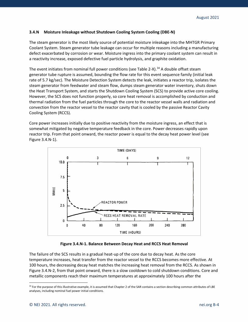
August 2021
© NEI 2021. All rights reserved. nei.org B-4
3.4.N Moisture Inleakage without Shutdown Cooling System Cooling (DBE-N)
The steam generator is the most likely source of potential moisture inleakage into the MHTGR Primary Coolant System. Steam generator tube leakage can occur for multiple reasons including a manufacturing defect exacerbated by corrosion or wear. Moisture ingress into the primary coolant system can result in a reactivity increase, exposed defective fuel particle hydrolysis, and graphite oxidation.
The event initiates from nominal full power conditions (see Table 2-X).34 A double offset steam generator tube rupture is assumed, bounding the flow rate for this event sequence family (initial leak rate of 5.7 kg/sec). The Moisture Detection System detects the leak, initiates a reactor trip, isolates the steam generator from feedwater and steam flow, dumps steam generator water inventory, shuts down the Heat Transport System, and starts the Shutdown Cooling System (SCS) to provide active core cooling. However, the SCS does not function properly, so core heat removal is accomplished by conduction and thermal radiation from the fuel particles through the core to the reactor vessel walls and radiation and convection from the reactor vessel to the reactor cavity that is cooled by the passive Reactor Cavity Cooling System (RCCS).
Core power increases initially due to positive reactivity from the moisture ingress, an effect that is somewhat mitigated by negative temperature feedback in the core. Power decreases rapidly upon reactor trip. From that point onward, the reactor power is equal to the decay heat power level (see Figure 3.4.N-1).
Figure 3.4.N-1. Balance Between Decay Heat and RCCS Heat Removal
The failure of the SCS results in a gradual heat-up of the core due to decay heat. As the core temperature increases, heat transfer from the reactor vessel to the RCCS becomes more effective. At 100 hours, the decreasing decay heat matches the increasing heat removal from the RCCS. As shown in Figure 3.4.N-2, from that point onward, there is a slow cooldown to cold shutdown conditions. Core and metallic components reach their maximum temperatures at approximately 100 hours after the 34 For the purpose of this illustrative example, it is assumed that Chapter 2 of the SAR contains a section describing common attributes of LBE analyses, including nominal fuel power initial conditions.

August 2021
© NEI 2021. All rights reserved. nei.org B-5
beginning of the event. The maximum core temperature peaks at 1,274 °C. The maximum control rod temperature reaches 863 °C, maximum core barrel temperature is 506 °C, and maximum vessel temperature is 392 °C. For the purpose of this analysis, the safe, stable end state is defined to be at approximately 300 hours, at which point the average core temperature has returned to its approximate value at the beginning of the event, RCCS heat removal exceeds core decay heat, and the reactor is slowly cooling toward cold shutdown conditions.
Figure 3.4.N-2. Core Temperature
Primary coolant pressure increases about 0.2 MPa following the rupture of the steam generator tube but decreases when the circulator trips and moisture ingress stops. As the core and structural material temperatures increase, the coolant pressure also increases to the point at which the pressure relief valve opens (7.1 MPa) at about 10 hours. Note that the pressure does not reach the nominal setpoint, but the probability of valve lift due to setpoint drift falls within the DBE region. The relief valve reseats at 6.1 MPa and does not open again. Coolant pressure decreases thereafter as the plant is cooled, as shown in Figure 3.4.N-3.

August 2021
© NEI 2021. All rights reserved. nei.org B-6
Figure 3.4.N-3. Primary Coolant Pressure
The total water inleakage is 267 kg. Tripping the Heat Transport System at the beginning of the event limits the amount of water inleakage that is available to oxidize graphite in the reactor vessel to 28 percent of the total inleakage, or 75 kg. The average fraction reaction in active core fuel elements is only 5.2×10⁻⁴ weight fraction. That value would increase to 1.8×10⁻³ weight fraction if all inleakage into the primary circuit were assumed to react. Bottom reflector blocks experience an average reaction of about 4×10⁻⁴ weight fraction. The reaction in core support materials (blocks and posts) is lower and does not significantly impair the core support capability of the structural materials.
With respect to the fuel, the high purity carbon is much less reactive than the bulk graphite, so there is no significant oxidation of the fuel. No fuel particle coatings should fail due to the steam in the environment. However, the small fraction of particles with defective coatings could be exposed to small amounts of water vapor diffusing through the graphite. 7.9 percent of iodine and noble gases in failed particles are released due to hydrolysis through the first 10 hours, when hydrolysis is complete.
The inleakage event results in the release of fission products to the primary circuit through four mechanisms: (i) hydrolysis of UCO particles with failed coatings, (ii) liberation of sorbed fission products in the bulk moderator graphite which is oxidized, (iii) diffusion of fission products out of failed particles due to elevated temperatures, and (iv) steam-induced vaporization and recirculation of fission products plated out on metallic surfaces. Based on all mechanisms, releases to the primary coolant are 300 Ci of noble gas, 440 Ci of iodine, and 142 Ci metallics. This compares to the nominal noble gas activity in the primary coolant of about 23 Ci.
The one-time relief through the primary system relief valve causes a release of 15 percent of the circulating gases and particulates. The total inventory in the primary coolant available for release to the environment (by mechanism of release) and the total released at 10 hours is shown in Table 3.4.N-1.

August 2021
© NEI 2021. All rights reserved. nei.org B-7
Table 3.4.N-1. Fission Products in Primary Coolant and Released from Primary Coolant at 10 Hours
Curies in Primary Coolant by Mechanism
Nuclide Initially Circulating
Hydrolysis of Failed Fuel
Graphite Oxidation
Recirculation of Plateout
Elevated Temperatures
Total (Ci)
Released (Ci)
Kr-85m 2.30 6.5 -- -- 0.1 8.90 1.33 Kr-88 5.16 17.3 -- -- 5.78 28.2 4.24 Rb-88 0.07 -- -- 3.12 -- 3.19 0.48 Sr-89 -- -- 0.220 1.03 -- 1.25 0.19 etc.
Based on that release, mean exclusion area boundary doses are calculated to be only 4×10⁻⁵ rem TEDE over a 30-day period, with 5th and 95th percentile values of 1.9×10⁻⁵ rem and 2.0×10⁻⁴ rem, respectively. These values are orders of magnitude below the F-C Target in the DBE region. The mechanistic source term is addressed in Section 2.J, and the dose analysis methodology is covered in Section 2.K.
The event is assumed to occur at any one of the four reactors on the plant site. The analysis was performed as part of the plant PRA, which is summarized in Section 2.1. The estimated frequency of the event is 4×10⁻⁴ per plant year with 5th and 95th percentile uncertainty values of 1×10⁻⁴ per plant year and 8×10⁻⁴ per plant year, respectively. Note that the frequency values are not based on analyses but are provided for illustrative purposes only.
SSCs performing PRA safety functions to mitigate the event are discussed in the narrative above.
B.3 Example BDBE Description
This writeup is based on a loss of heat sink event without reactor trip for the PRISM reactor. Information is taken from Appendix E.4 of the PRISM Preliminary Safety Information Document.35 This BDBE has no consequences so it does not bound the risks of a collection of BDBEs, and the example writeup with plots goes beyond the minimum content outlined in Section 3.5.1 of the guidance.
3.5.N Loss of Heat Sink without Reactor Trip (BDBE-N)
The PRISM reactor is assumed to undergo a loss of the Intermediate Heat Transfer System from beginning of cycle hot full power conditions (see Table 2-X)36 with a concurrent failure of the reactor control and protection systems to reduce power or trip the reactor. The event occurs with a beginning of cycle core configuration, which minimizes negative reactivity feedback.
The primary temperatures increase due to the loss of the primary heat sink. The core inlet region rapidly heats up to 980 °F. The resulting expansion of the radial gridplate provides substantial negative reactivity (approximately $0.68). The net reactivity remains negative throughout the event, shutting down the fission reaction as shown in Figure 3.5.N-1. Primary temperatures remain elevated as shown in
35 GEFR-00793, “PRISM Preliminary Safety Information Document,” Volume IV, Appendix E, General Electric, December 1987. 36 For the purpose of this illustrative example, it is assumed that Chapter 2 of the SAR contains a section describing common attributes of LBE analyses, including nominal fuel power initial conditions.

August 2021
© NEI 2021. All rights reserved. nei.org B-8
Figures 3.5.N-2 and 3.5.N-3, with primary system heat input balanced by heat removal from the Reactor Vessel Auxiliary Cooling System and the Auxiliary Cooling System.
Figure 3.5.N-1. Core Power and Primary System Flow
Figure 3.5.N-2. Reactivity

August 2021
© NEI 2021. All rights reserved. nei.org B-9
Figure 3.5.N-3. Primary Coolant Temperature
Fuel and core temperatures are shown on Figures 3.5.P-4 and 3.5.P-5. BDBE success criteria are documented in Section 2.R.37 For this event the applicable thermal criteria are summarized below. All criteria are met, so there are no dose consequences for the event.
• Cladding midwall temperature less than 1450 °F (initial period)
• Peak fuel-cladding interface temperature less than 1290 °F (long-term)
• Peak fuel-cladding interface temperature less than 1450 °F (short-term)
• Peak fuel centerline temperature less than 2000 °
• Peak sodium temperature less than 1800 °F
37 For the purpose of this illustrative example, it is assumed that the BDBE success criteria are documented in Chapter 2.

August 2021
© NEI 2021. All rights reserved. nei.org B-10
Figure 3.5.N-4. Peak Fuel-Cladding Midwall and Sodium Core Outlet Temperatures
Figure 3.5.N-5. Fuel Temperatures

August 2021
© NEI 2021. All rights reserved. nei.org B-11
The reactor has attained a safe, stable end state by 2000 seconds, with the core shutdown and primary system heat being removed by the Reactor Vessel Auxiliary Cooling System and the Auxiliary Cooling System.
The analysis was performed as part of the plant PRA, which is summarized in Section 2.1. The estimated frequency of the event is 9×10⁻⁷ per plant year with 5th and 95th percentile uncertainty values of 2×10⁻⁷ per plant year and 5×10⁻⁶ per plant year, respectively. Note that the aforementioned frequency values are illustrative and not based on actual PRA calculations for PRISM.
B.4 Example DBA Description
This writeup is based on a moisture inleakage event for a modular high-temperature gas reactor, with information taken from the MHTGR PSID Section 15.13.7.33 Note that the PSID uses the nomenclature “Safety Related Design Conditions” instead of DBAs.
3.6.N Moisture Inleakage Without SCS Cooling (DBA-N)
This MHTGR DBA is derived from the corresponding moisture inleakage DBE-N (see Appendix B.2). The initiating event is the same, but for the DBA it is assumed that only safety-related SSCs are available to mitigate the consequences.
The event initiates from nominal full power conditions (see Table 2-X).38 A double offset steam generator tube rupture is assumed with an initial leak rate of 5.7 kg/sec. Following the leak in the steam generator, the resulting moisture ingress into the primary coolant causes a rapid increase in primary coolant moisture concentration and within a few seconds the moisture produces an increase in core reactivity. Core power rises such that the reactor trip setpoint on high core power-to-flow ratio of 1.5 is achieved at 8 seconds, at which time the outer reflector rods are tripped. Figure 3.6.N-1 shows the reactor power during this event.
38 For the purpose of this illustrative example, it is assumed that Chapter 2 of the SAR contains a section describing common attributes of LBE analyses, including nominal fuel power initial conditions.

August 2021
© NEI 2021. All rights reserved. nei.org B-12
Figure 3.6.N-1. Reactor Power
Normally, the Moisture Detection System would detect the leak, initiate a reactor trip, isolate the steam generator from feedwater and steam flow, dump steam generator water inventory, shut down the Heat Transport System, and start the SCS to provide core cooling. However, for the DBA analysis the non-safety-related Moisture Detection system is assumed to be unavailable. Also, the neutron flux controller should mitigate the reactor power increase at the beginning of the event by inserting control reactivity to maintain reactor power, but the non-safety-related controller is also assumed to be unavailable. Moreover, credit is taken for successful closure of the safety-related steam generator isolation valves and opening of the safety-related primary system safety valve, but the non-safety-related steam generator dump valves are assumed to fail which increases the quantity of water/stream ingress to the primary system.
As the primary coolant pressure continues to increase due to inleakage, the reserve shutdown control (RSC) equipment is tripped at 326 seconds when the pressure reaches the setpoint of 7.0 MPa. The RSC material is inserted into the core to maintain reactor subcriticality. At the same time, the main loop is also shut down on high pressure. The main circulator is tripped, and the steam generator is isolated. About 1860 kg of steam enters the primary system prior to steam generator isolation. Depending on the location of the leak, a large portion of the steam generator inventory can subsequently enter the primary system, with as much as 2200 kg flashing to steam. The differential pressure that initially drives the inleakage decreases with time, so that the ingress rate of steam after isolation ramp from 5.7 kg/sec to zero over about 13 minutes. Once pressure equilibrates, water may continue to enter the primary coolant, but in the absence of a heat source it is assumed to remain in the steam generator vessel as liquid. Therefore, the water is unavailable to react with the core. Furthermore, due to the lack of forced circulation between the steam generator vessel and the reactor vessel, only the steam in the reactor and reactor plenums (28 percent of the total steam inleakage) is available to react with the core.
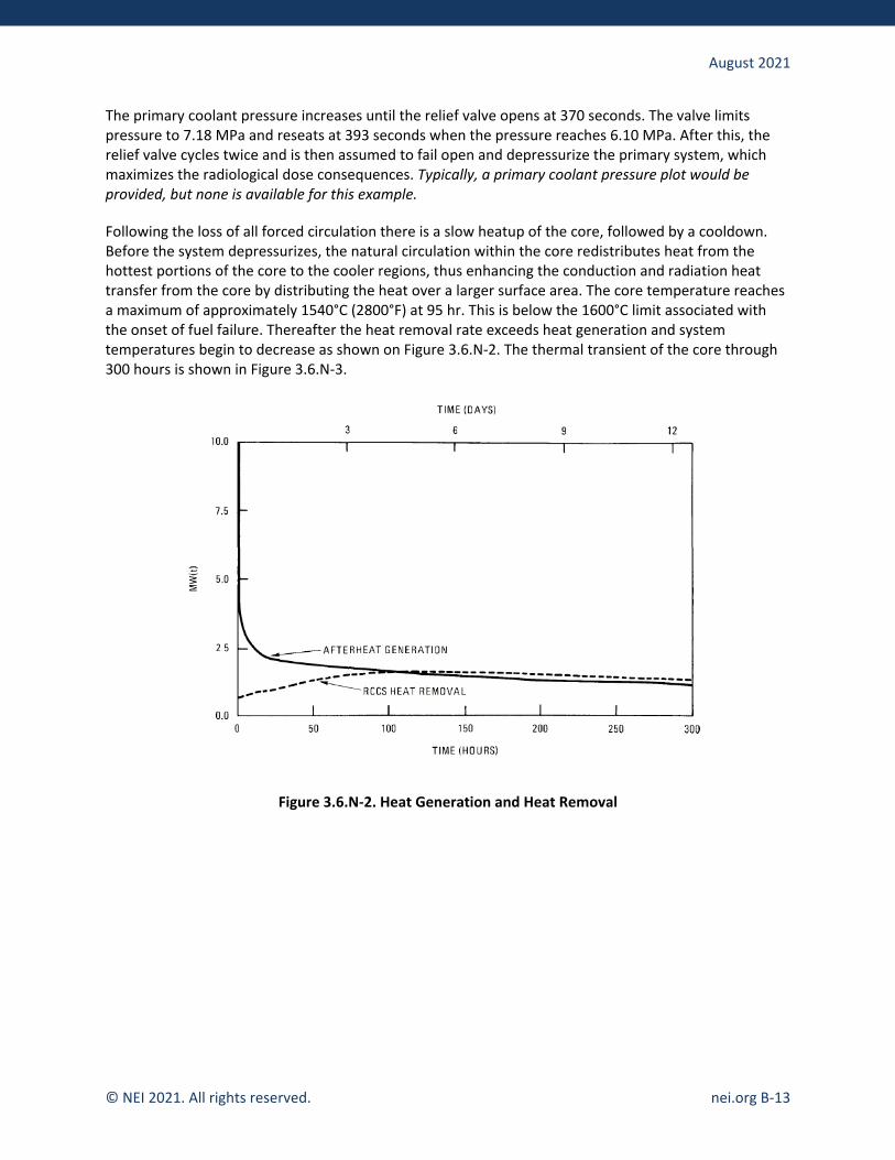
August 2021
© NEI 2021. All rights reserved. nei.org B-13
The primary coolant pressure increases until the relief valve opens at 370 seconds. The valve limits pressure to 7.18 MPa and reseats at 393 seconds when the pressure reaches 6.10 MPa. After this, the relief valve cycles twice and is then assumed to fail open and depressurize the primary system, which maximizes the radiological dose consequences. Typically, a primary coolant pressure plot would be provided, but none is available for this example.
Following the loss of all forced circulation there is a slow heatup of the core, followed by a cooldown. Before the system depressurizes, the natural circulation within the core redistributes heat from the hottest portions of the core to the cooler regions, thus enhancing the conduction and radiation heat transfer from the core by distributing the heat over a larger surface area. The core temperature reaches a maximum of approximately 1540°C (2800°F) at 95 hr. This is below the 1600°C limit associated with the onset of fuel failure. Thereafter the heat removal rate exceeds heat generation and system temperatures begin to decrease as shown on Figure 3.6.N-2. The thermal transient of the core through 300 hours is shown in Figure 3.6.N-3.
Figure 3.6.N-2. Heat Generation and Heat Removal

August 2021
© NEI 2021. All rights reserved. nei.org B-14
Figure 3.6.N-3. Maximum and Average Core Temperatures
Offsite releases of radioactivity from the event are due to: 1) the release of circulating activity, 2) steam-induced vaporization and recirculation of plated-out activity, 3) release of a small fraction of the fuel activity due to the temperature transient, 4) release of fission products contained in the matrix and structural graphite that becomes oxidized, and 5) release due to the hydrolysis of failed fuel. The recirculation of plateout and the hydrolysis of failed fuel before the depressurization are the major contributors to iodine and noble gas release. The cumulative number of curies released from the vessel as a function of time is shown in Figure 3.6.N-4 for the important nuclides that contribute to dose. Dose to a receptor at the EAB is calculated mechanistically considering the phenomena of plateout and settling in the Reactor Building, radioactive decay, and atmospheric dispersion. The mean exclusion area boundary dose is conservatively calculated to be 0.045 rem total effective dose equivalent (TEDE) over a 30-day period. This value is well below the 10 CFR 50.34 EAB two hour dose limit of 25 rem TEDE. The mechanistic source term is addressed in Section 2.J, and the dose analysis methodology is covered in Section 2.K.
The reactor has achieved its safe, stable end state by 300 hours when the analysis is terminated. The fundamental safety functions of controlling heat generation, controlling heat removal, controlling chemical attack, and retaining radionuclides have been achieved.

August 2021
© NEI 2021. All rights reserved. nei.org B-15
Figure 3.6.N-4. Curies of Selected Radionuclides Released from the Reactor Vessel