Technology INA UniAir® System
16
Technology INA UniAir ® System
Transcript of Technology INA UniAir® System

Technology
INA UniAir® System
2
Page
1. Introduction 3
2. The Benefits of the UniAir® System 4
3. Design and Operating Principle 6
3.1 The UniAir® Actuator 6
3.2 Switching Valves 11
3.3 Temperature Sensor for Engine Oil Viscosity 13
3.4 Characteristics 13
Content
3
1. Introduction
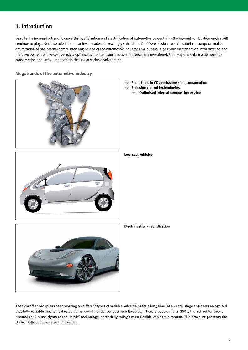
g Reductions in CO2 emissions/fuel consumption
g Emission control technologies g Optimised internal combustion engine
Low-cost vehicles
Electrification/hybridization
Megatrends of the automotive industry
Despite the increasing trend towards the hybridization and electrification of automotive power trains the internal combustion engine will
continue to play a decisive role in the next few decades. Increasingly strict limits for CO2 emissions and thus fuel consumption make
optimization of the internal combustion engine one of the automotive industry’s main tasks. Along with electrification, hybridization and
the development of low-cost vehicles, optimization of fuel consumption has become a megatrend. One way of meeting ambitious fuel
consumption and emission targets is the use of variable valve trains.
The Schaeffler Group has been working on different types of variable valve trains for a long time. At an early stage engineers recognized
that fully-variable mechanical valve trains would not deliver optimum flexibility. Therefore, as early as 2001, the Schaeffler Group
secured the license rights to the UniAir® technology, potentially today’s most flexible valve train system. This brochure presents the
UniAir® fully-variable valve train system.
4
The variable valve train is one of the key technologies for imple-menting low-CO2 emission strategies. In the currently available systems variable valve control is typically made possible by parallel shifting of the opening and closing time (phase shift) and/or variations of the intake valve stroke. The phase shift technology uses a hydraulic phasing rotor to vary the position of the camshaft
relative to crankshaft which allows the system to optimize exhaust gas recirculation and the effective compression ratio. Variable valve lift can be achieved by means of an eccentric shaft driven by a servomotor. Systems with variable lift can have discrete two- or three-step lift actuation or be fully variable.
2. The Benefits of the UniAir® System
Valve train systems
Valve liftPhase shift
Continuous
g Hydraulic
g Electro-mechanical
Discrete
g Two-stage g Switching tappet g Support element g Lever g Cam shifting system g Roller-type tappet
g Three-stage g Lever g Cam shifting system
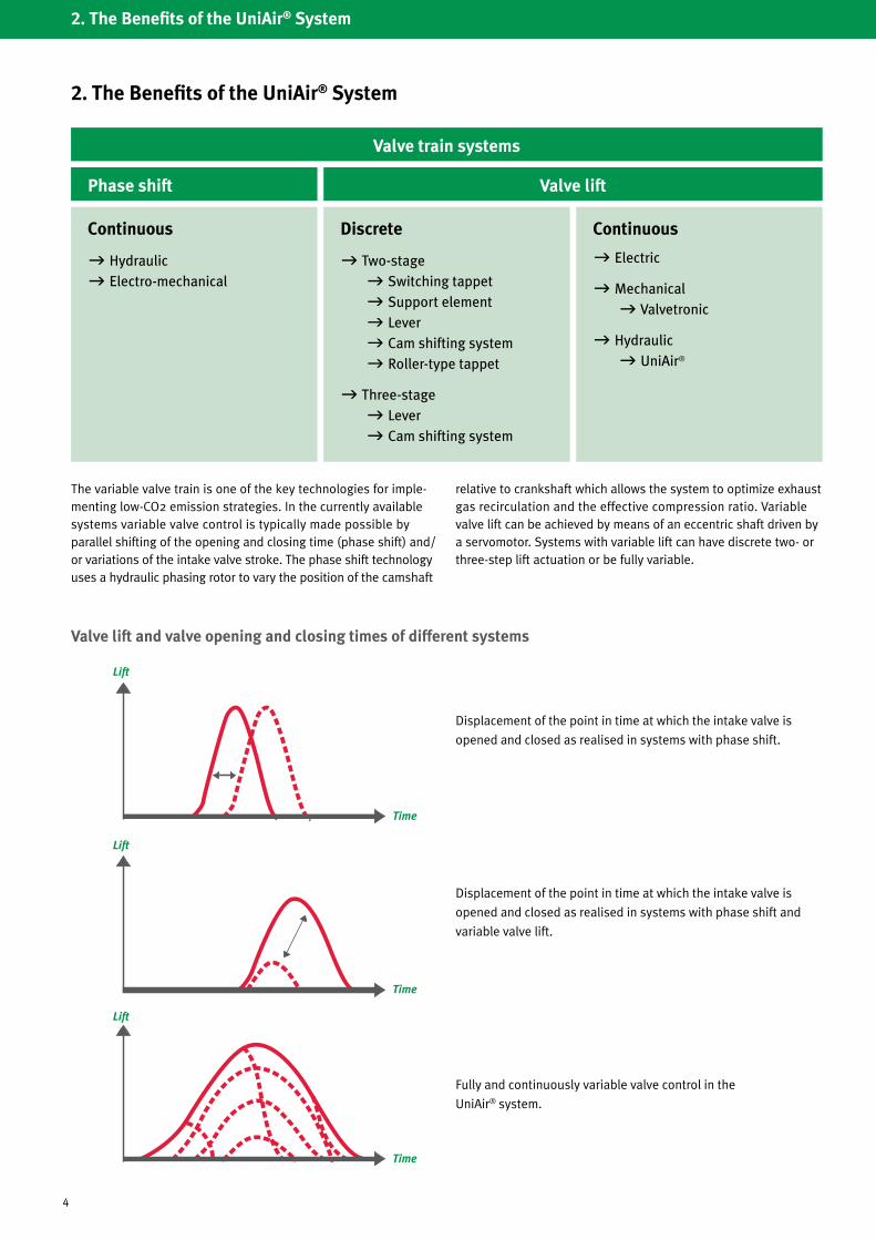
Valve lift and valve opening and closing times of different systems
Lift
Lift
Lift
Time
Time
Time
Displacement of the point in time at which the intake valve is
opened and closed as realised in systems with phase shift.
Displacement of the point in time at which the intake valve is
opened and closed as realised in systems with phase shift and
variable valve lift.
Fully and continuously variable valve control in the
UniAir® system.
2. The Benefits of the UniAir® System
Continuous
g Electric
g Mechanical g Valvetronic
g Hydraulic g UniAir®
5
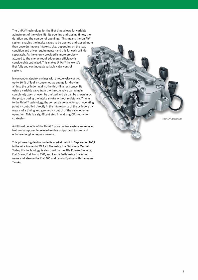
The UniAir® technology for the first time allows for variable adjustment of the valve lift , its opening and closing times, the duration and the number of openings. This means the UniAir®
system enables the intake valves to be opened and closed more than once during one intake stroke, depending on the load condition and driver requirements - and this for each cylinder separately. As the energy provided is more precisely attuned to the energy required, energy efficiency is considerably optimized. This makes UniAir® the world‘s first fully and continuously variable valve control system.
In conventional petrol engines with throttle valve control, up to 10 % of fuel is consumed as energy for drawing air into the cylinder against the throttling resistance. By using a variable valve train the throttle valve can remain completely open or even be omitted and air can be drawn in by the piston during the intake stroke without resistance. Thanks to the UniAir® technology, the correct air volume for each operating point is controlled directly in the intake ports of the cylinders by means of a timing and geometric control of the valve opening operation. This is a significant step in realizing CO2 reduction strategies.
Additional benefits of the UniAir® valve control system are reduced fuel consumption, increased engine output and torque and enhanced engine responsiveness.
This pioneering design made its market debut in September 2009 in the Alfa Romeo MITO 1.4 l Fire using the Fiat name MultiAir. Today, this technology is also used on the Alfa Romeo Giulietta, Fiat Bravo, Fiat Punto EVO, and Lancia Delta using the same name and also on the Fiat 500 and Lancia Epsilon with the name TwinAir.
UniAir® actuator

6
3. Design and Operating Principle
3.1 The UniAir® Actuator
The UniAir® actuator controls the opening and closing of the intake valves. The intake camshaft is no longer required; instead the UniAir® actuator is located on the cylinder head. The UniAir® actuator features one phaser for each cylinder, which actuates the intake valves using the engine oil. Depending on the engine set-up (8 or 16 valves) each phaser actuates one or two intake valves per cylinder.
The UniAir® actuator is driven via specially designed cams on the exhaust camshaft; it is electronically controlled by the engine control unit. For petrol engines, this enables throttle-free, conti-nuously variable and software-based load control across the entire engine map.
Unlike conventional or electro-mechanical valve trains where the cam contour is transferred to the engine valve via a rigid element (such as a tappet or finger follower), UniAir® uses a defined volume of oil that is confined in the high-pressure chamber.
This oil volume can be varied using a 2-2-way switching valve. When the switching valve is closed, the oil acts as a hydraulically rigid pushrod.
When the switching valve is open, engine oil flows through the oil gallery into the intermediate pressure chamber and pressure accumulator; the cam and the valve are thus disconnected.
For as long as the cam is on the base circle the mechanical pressure accumulator ensures that any oil forced out of the high pressure chamber is returned to it. The pressure accu-
mulator also serves to supply the system volume with exactly the amount of oil required for the next
cycle.

7
On engines with conventional valve timing systems the intake valve is opened and closed across the complete cam profile. The UniAir® system makes valve lift entirely independent of the cam profile. Maximum valve lift during the complete cam lift stroke will only occur if the switching valve is closed. Engine oil is fed directly to the hydraulic pushrod, which opens the intake valve.
To prevent the valves from knocking on the valve seating, every valve features a hydraulic end stop brake unit. This brake assembly reduces the valve‘s closure speed. Shortly before the valve hits the seat the hydraulic brake unit is actuated and provides for a regularsmooth closure. This protects the valve seating material and ensures longer part life. This solution also allows for a hydraulic valve lash adjustment mechanism to be incorporated.
Decoupling of the valve lift from the cam profile also makes zero lift possible. In this mode, the switching valve remains open all the time resulting in the intake valve being closed. Engine oil is fed via the oil channel and the open switching valve to the intermediate pressure chamber and the pressure accumulator.
From maximum to zero lift, UniAir® provides an infinite number of continuously variable valve lift events. Late closing of the switching valve, for example, may result in late opening of the intake valve where as early opening of the switching valve results in earlier closing of the intake valve (see figures page 8).
Both events are independent of each other and allow for variations in valve lift length and frequency during one intake stroke.
Phaser Design
Pressure accumulator
Pump element
Roller-type finger follower
Exhaust camshaft
Slave cylinder with hydraulic end stop brake unit
High-pressure chamber
Solenoid Valve
Intermediate pressure chamber with oil inlet and outlet
8
3. Design and Operating Principle
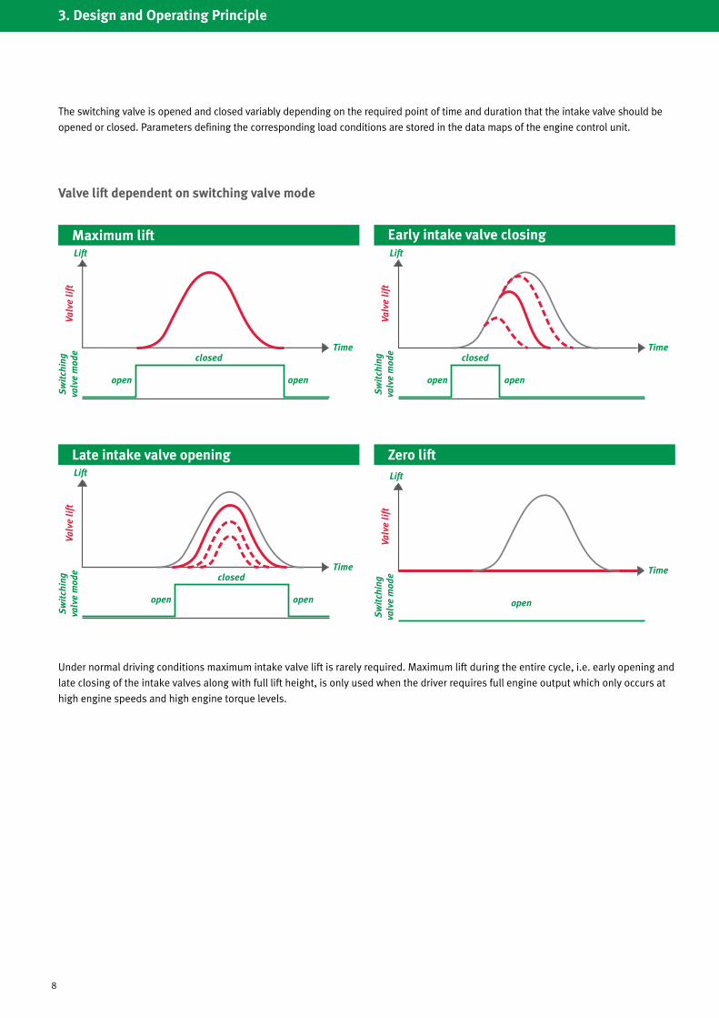
Valve lift dependent on switching valve mode
The switching valve is opened and closed variably depending on the required point of time and duration that the intake valve should be
opened or closed. Parameters defining the corresponding load conditions are stored in the data maps of the engine control unit.
Maximum liftLift
Time
Valv
e li
ftS
wit
chin
g va
lve
mod
e closed
open open
Under normal driving conditions maximum intake valve lift is rarely required. Maximum lift during the entire cycle, i.e. early opening and
late closing of the intake valves along with full lift height, is only used when the driver requires full engine output which only occurs at
high engine speeds and high engine torque levels.
Early intake valve closingLift
Time
Valv
e li
ftS
wit
chin
g va
lve
mod
e closed
open open
Late intake valve openingLift
Time
Valv
e li
ftS
wit
chin
g va
lve
mod
e closed
open open
Zero liftLift
Time
Valv
e li
ftS
wit
chin
g va
lve
mod
e
open
9
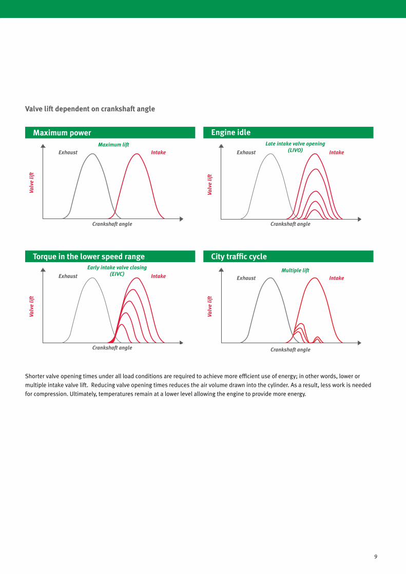
Valve lift dependent on crankshaft angle
Shorter valve opening times under all load conditions are required to achieve more efficient use of energy; in other words, lower or
multiple intake valve lift. Reducing valve opening times reduces the air volume drawn into the cylinder. As a result, less work is needed
for compression. Ultimately, temperatures remain at a lower level allowing the engine to provide more energy.
Valv
e li
ft
Maximum powerMaximum lift
Exhaust Intake
Crankshaft angle
Engine idle
Valv
e li
ft
Late intake valve opening (LIVO)Exhaust Intake
Crankshaft angle
Torque in the lower speed range
Valv
e li
ft
Early intake valve closing (EIVC)Exhaust Intake
Crankshaft angle
City traffic cycle
Valv
e li
ft
Multiple liftExhaust Intake
Crankshaft angle

10
3. Design and Operating Principle
Valve control dependent on engine torque and speed
Peak performance
g Maximum lift
g Late valve closing (long valve opening)
g Maximum valve overlap
Max. torqueMax. volumetric efficiency
g Early valve closing (short valve opening)
Optimised combustion Optimised combustion
g Multiple lift (charge movement)
Engine speed
Torq
ue

11
Target angle and mode
Early intake valve closing mode
Late intake valve opening mode
Late intake valve opening
Early intake valve closing
Switching valve open
Switching valve closed
Switching valve open
Switching valve open
Switching valve closed
Switching valve open
3.2 Switching Valves
Extremely high levels of accuracy are required by the UniAir® system to ensure constantly identical valve lifts of the same valve and for each actuator over the entire cylinder head. It is crucial that all components ranging from pump to brake conform to the specified tolerances. The solenoid valves as the control devices for every required lift curve are of central importance for the overall system. During the design phase of this new switching valve, the developers were faced with special challenges such as the required on and off times, the switching time precision and durability.
System design with a “normally open” switching valve requires the valve to switch once per rotation of the camshaft and even several times during multi-lift operation. To ensure that the high-pressure chamber is full and therefore to ensure full lift during the next cycle, the switching valve is opened for a short time after each cycle to ensure refilling of the chamber. In the case of multi-lift operation, it must be ensured that the armature has reached its resting position again after opening for the first time before the switching valve is activated a second time. Therefore, current for the second lift can only be fed after the armature has been in the resting position for approx. 2 milliseconds.
The figure below shows the activation curve of the current for a switching valve and the corresponding engine valve lift curve. The diagram compares early intake valve closing with the full lift curve.
A special
activation strategy was developed
for the switching valve current in order to produce a fast-acting switching valve with the lowest possible current requirements. The current profile comprises several sections.
The non activated switching valve is first fed with the bias current, which pre-magnetizes the switching valve but does not switch it. In order to ensure a rapid and precise energizing procedure, increased peak current is applied at the time of switching. The switching point is determined by the software depending on the operating condition.
After the switching valve has been actuated completely, the current is reduced to holding current, which keeps the switching valve closed. In turn, the software determines the point in time at which the current is completely switched off, thereby opening the switching valve again.
Lift
Current

12
3. Design and Operating Principle
The precision of the opening and closing angles of the engine valves is essential for system function. The switching time precision of the switching valve makes a considerable contribution in this regard. During the assembly of the switching valves and their sub-assemblies, various functional values such as flow and switching times are measured on the assembly line and the assemblies are adjusted so these values are within the required range. In addition, a special compensation mechanism is used to optimize switching time accuracy. This compensation is active during the entire lifecycle of the product and therefore also counter-acts changes in switching times caused by ageing. This ensures optimum balancing of the cylinder charge throughout the entire engine life.
The switching valves carry out around 330 million switching operations each during the operating life of the system. This number of switching cycles at the required precision poses a significant challenge for the development of the switching valve. This new switching valve was developed from the concept phase to volume production readiness using the most advanced design and simulation methods in cooperation with Continental Automotive Systems. The function was accurately validated and the switching valve was integrated in the overall system by means of several function and operating life tests on component test stands, system test stands and in vehicles.
The switching valves are individually controlled by the control software via corresponding power stages. The function of the control software is to implement the modes and opening and closing angles of the engine valves as defined by the engine control system. Here, the software considers various factors that influence the behaviour of the system in order to find the correct actuation point of the switching valve in each case. It therefore determines the timing of the engine valves.
The First step is to understand the on and off cycle of each switching valve. They are individually monitored using the current curve during each switching process for each cylinder and then re-adjusted depending on the operating condition using data maps in the engine control system. The challenge in this case is the detectability of the current curve over the entire required temperature range and the oil viscosity associated with it. All switching valve components must be perfectly matched to each other to ensure this function.
The system architecture and the component geometry alsodetermine the characteristics of the valve lift curve. This includes the end stop brake unit. This unit is a slave cylinder that converts the hydraulic pressure into the movement of the engine valve via a hydraulic valve lash adjustment element. Since the engine valve is always closed independently of the cam contour, it is not slowed down mechanically before it lands.
To prevent excessive closure speeds that can generate noise and damage the valve, the engine valve is decelerated at the end of its rapid closing phase by means of hydraulic control in the brake piston.
This in return enables fast opening speeds as the brake is short-circuited by means of a special check valve. Designing all these components in a specific manner ensures that the engine valve is closed in good time under cold conditions (down to -30 °C in Europe and -35 °C in USA) and low closure speeds with hot engine oil.
13
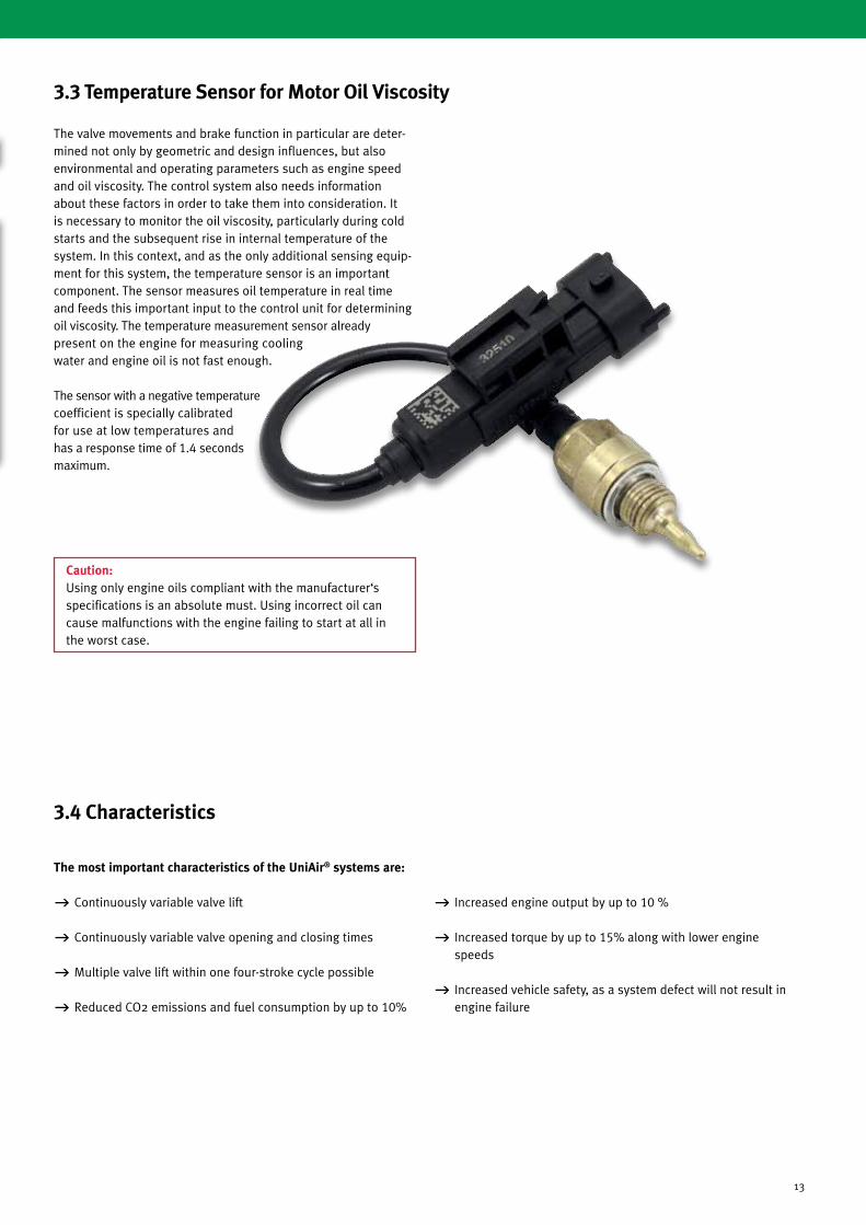
3.3 Temperature Sensor for Motor Oil Viscosity
The valve movements and brake function in particular are deter-mined not only by geometric and design influences, but also environmental and operating parameters such as engine speed and oil viscosity. The control system also needs information about these factors in order to take them into consideration. It is necessary to monitor the oil viscosity, particularly during cold starts and the subsequent rise in internal temperature of the system. In this context, and as the only additional sensing equip-ment for this system, the temperature sensor is an important component. The sensor measures oil temperature in real time and feeds this important input to the control unit for determining oil viscosity. The temperature measurement sensor already present on the engine for measuring cooling water and engine oil is not fast enough.
The sensor with a negative temperature coefficient is specially calibrated for use at low temperatures and has a response time of 1.4 seconds maximum.
Caution: Using only engine oils compliant with the manufacturer‘s specifications is an absolute must. Using incorrect oil can cause malfunctions with the engine failing to start at all in the worst case.
3.4 Characteristics
The most important characteristics of the UniAir® systems are:
g Continuously variable valve lift
g Continuously variable valve opening and closing times
g Multiple valve lift within one four-stroke cycle possible
g Reduced CO2 emissions and fuel consumption by up to 10%
g Increased engine output by up to 10 %
g Increased torque by up to 15% along with lower engine speeds
g Increased vehicle safety, as a system defect will not result in engine failure

14
Notes
Notes

15
Notes