
Technology for High Performance WLANs
44
Technology for High Performance WLANs Serving The Needs Of Higher Education
description
Technology for High Performance WLANs. Serving The Needs Of Higher Education. Agenda. Meru Networks – Our Mission Why 802.11 WLANs require QoS for Voice and Data Meru’s QoS Architecture Comparing QoS Solutions Converged Network Case Study High Performance b/g Network Co-Existence - PowerPoint PPT Presentation
Transcript of Technology for High Performance WLANs
Technology for High Performance WLANs
Serving The Needs Of
Higher Education
2
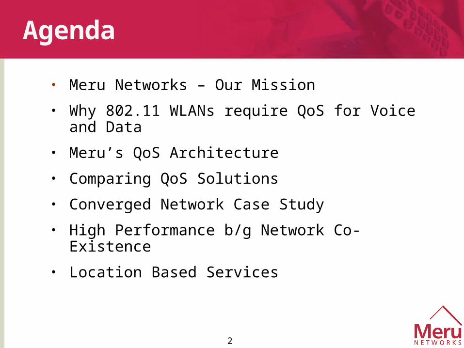
Agenda
• Meru Networks – Our Mission
• Why 802.11 WLANs require QoS for Voice and Data
• Meru’s QoS Architecture
• Comparing QoS Solutions
• Converged Network Case Study
• High Performance b/g Network Co-Existence
• Location Based Services
3
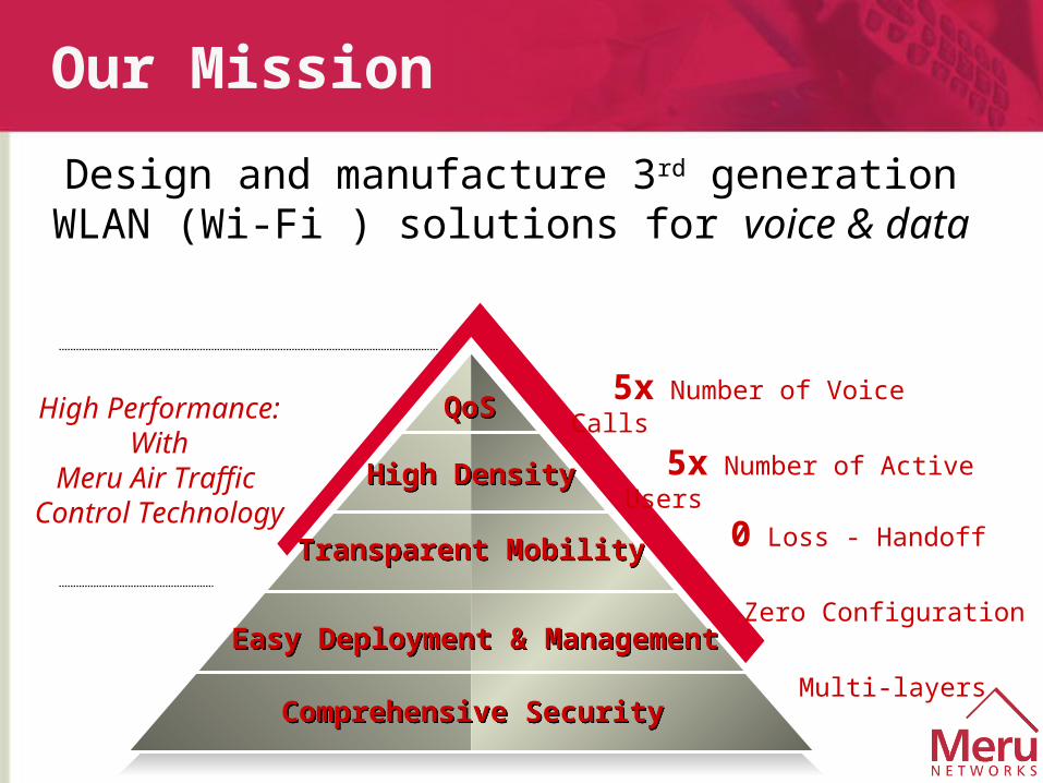
Our Mission
Design and manufacture 3rd generation WLAN (Wi-Fi ) solutions for voice & data
Comprehensive SecurityComprehensive Security
Easy Deployment & ManagementEasy Deployment & Management
Transparent MobilityTransparent Mobility
High DensityHigh Density
QoSQoS
Zero Configuration
Multi-layers
5x Number of Voice Calls
5x Number of Active Users
0 Loss - Handoff
High Performance:With
Meru Air Traffic Control Technology
4
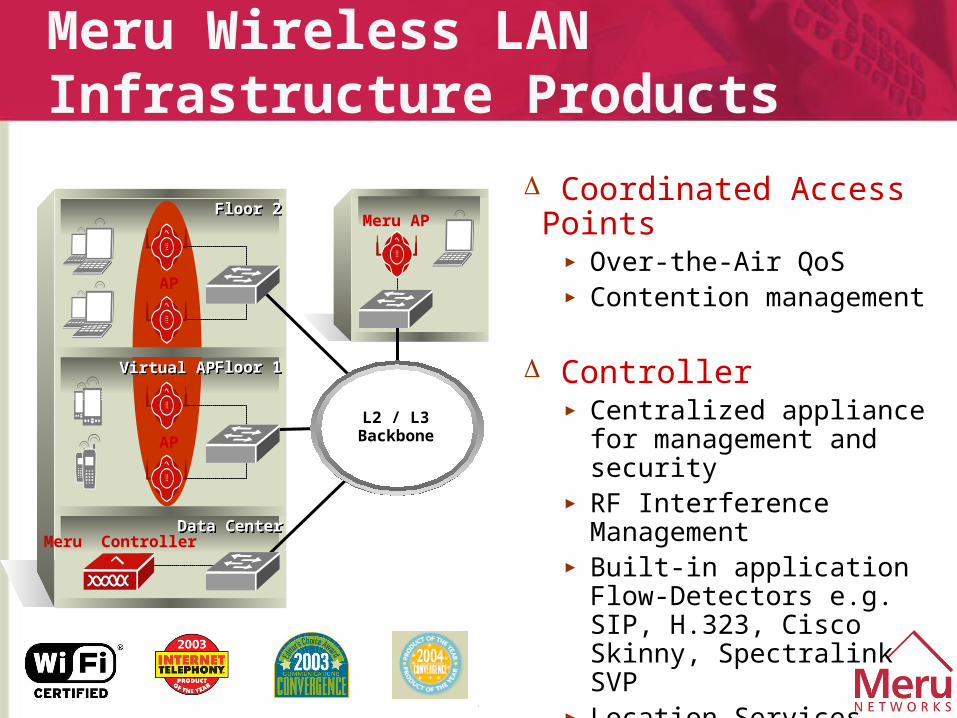
Meru Wireless LAN Infrastructure Products
Floor 2Floor 2
Floor 1Floor 1
Data CenterData Center
L2 / L3Backbone
Virtual APVirtual AP
AP
AP
Meru Controller
Meru AP
Coordinated Access Points► Over-the-Air QoS► Contention management
Controller► Centralized appliance for
management and security► RF Interference Management► Built-in application
Flow-Detectors e.g. SIP, H.323, Cisco Skinny, Spectralink SVP
► Location Services
5
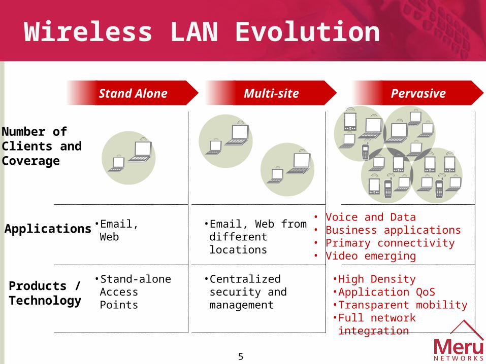
Wireless LAN Evolution
Number of Clients and Coverage
Applications
Products /Technology
• Email, Web
• Stand-aloneAccess Points
Stand Alone Multi-site
• Email, Web from different locations
• Centralized security and management
• High Density• Application QoS• Transparent mobility• Full network integration
• Voice and Data• Business applications• Primary connectivity• Video emerging
Pervasive
6
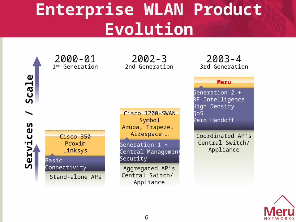
Enterprise WLAN Product Evolution
Generation 1 + Central ManagementSecurity
2000-011st Generation
2002-32nd Generation
2003-43rd Generation
Aggregated AP’sCentral Switch/
ApplianceStand-alone APs
Cisco 1200+SWANSymbol
Aruba, Trapeze, Airespace …
Meru
Generation 2 + RF IntelligenceHigh DensityQoSZero Handoff
Cisco 350ProximLinksys
Basic Connectivity
Ser
vice
s /
Sca
le
Coordinated AP’sCentral Switch/
Appliance
7
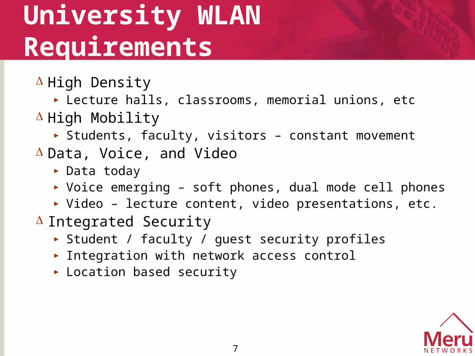
University WLAN Requirements
High Density► Lecture halls, classrooms, memorial unions, etc
High Mobility► Students, faculty, visitors – constant movement
Data, Voice, and Video► Data today► Voice emerging – soft phones, dual mode cell phones► Video – lecture content, video presentations, etc.
Integrated Security► Student / faculty / guest security profiles► Integration with network access control► Location based security
8
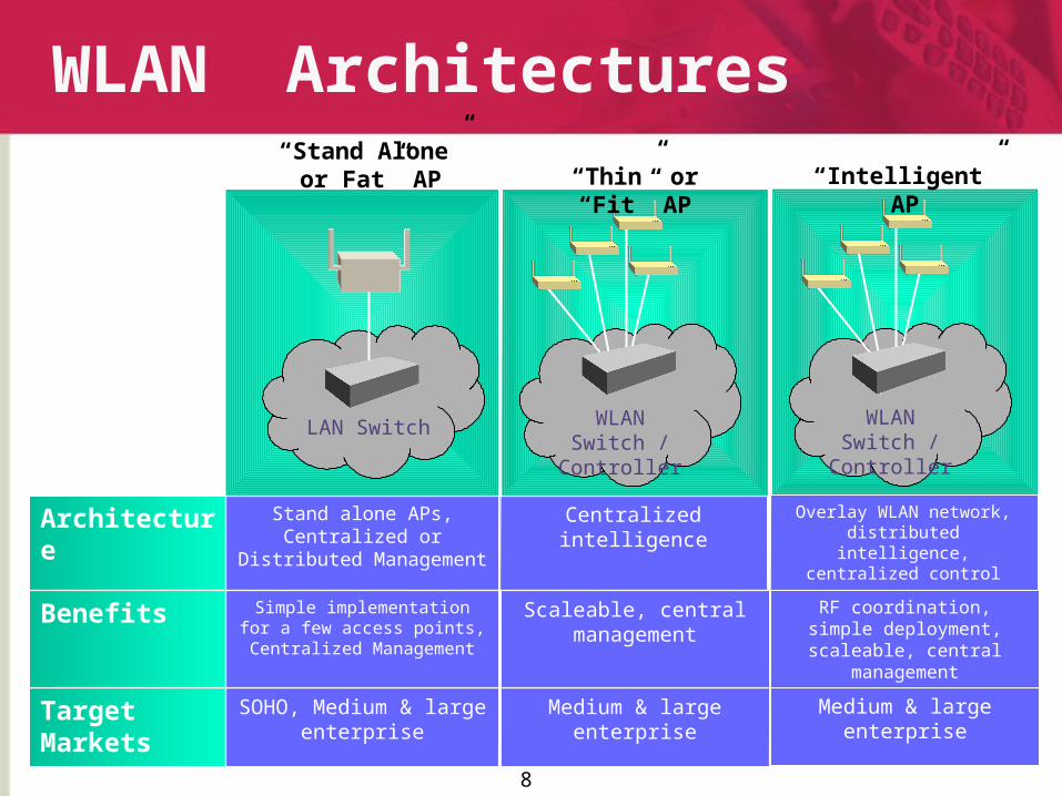
WLAN Architectures
Medium & large enterprise
Scaleable, central management
Centralized intelligence
SOHO, Medium & large enterprise
Target Markets
Simple implementation for a few access points,
Centralized Management
Benefits
Stand alone APs, Centralized or Distributed
Management
Architecture
“Stand Alone” or Fat” AP “Thin” or “Fit” AP
LAN Switch WLAN Switch / Controller
Medium & large enterprise
RF coordination, simple deployment, scaleable,
central management
Overlay WLAN network, distributed intelligence,
centralized control
“Intelligent” AP
WLAN Switch / Controller
9
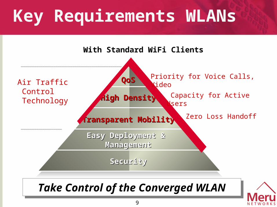
Key Requirements WLANs
SecuritySecurity
Easy Deployment & Management
Easy Deployment & Management
Transparent MobilityTransparent Mobility
High DensityHigh Density
QoSQoS Priority for Voice Calls, Video
Capacity for Active Users
Zero Loss Handoff
Air Traffic Control
Technology
With Standard WiFi Clients
Take Control of the Converged WLAN
Take Control of the Converged WLAN
10
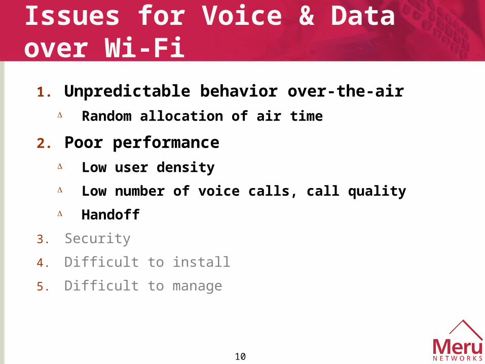
Issues for Voice & Data over Wi-Fi
1. Unpredictable behavior over-the-air Random allocation of air time
2. Poor performance Low user density
Low number of voice calls, call quality
Handoff
3. Security
4. Difficult to install
5. Difficult to manage
11
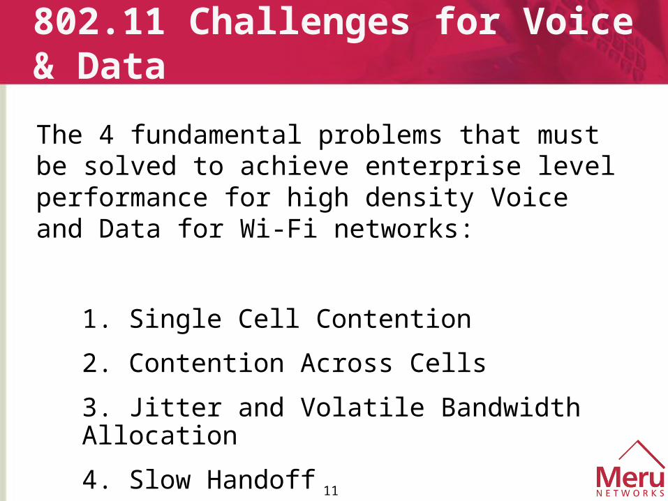
802.11 Challenges for Voice & Data
The 4 fundamental problems that must be solved to achieve enterprise level performance for high density Voice and Data for Wi-Fi networks:
1. Single Cell Contention
2. Contention Across Cells
3. Jitter and Volatile Bandwidth Allocation
4. Slow Handoff
12
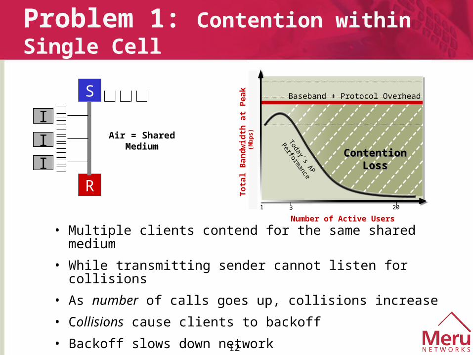
Problem 1: Contention within Single Cell
20
5
8
11
1 3
Baseband + Protocol Overhead
ContentionLoss
ContentionLoss
Today’s AP
Performance
Number of Active Users
To
tal
Ba
nd
wid
th a
t P
ea
k
(Mb
ps
)
• Multiple clients contend for the same shared medium
• While transmitting sender cannot listen for collisions
• As number of calls goes up, collisions increase
• Collisions cause clients to backoff
• Backoff slows down network
• Requires more than scheduling
S
R
I
I
I
Air = Shared Medium
13
5.5/11Mbps
CS
Rec
eive
Sig
nal
at
AP
1Mbps
Distance
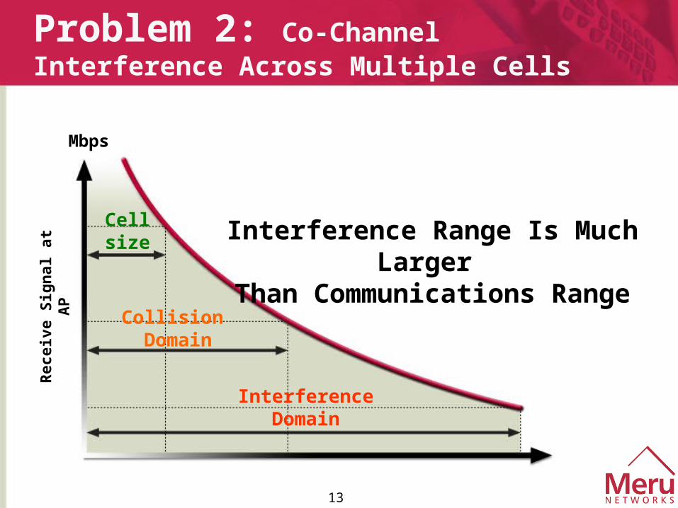
Problem 2: Co-Channel Interference Across Multiple Cells
Cellsize
Collision Domain
InterferenceDomain
Interference Range Is Much Larger
Than Communications Range
Mbps
14
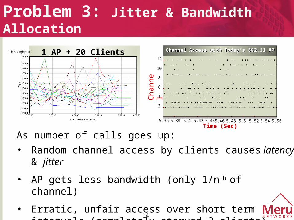
Problem 3: Jitter & Bandwidth Allocation
5.46 5.48 5.5 5.52 5.54 5.56Time (Sec)
Channel Access with Today’s 802.11 APChannel Access with Today’s 802.11 AP
2
6
4
8
10
12
5.36 5.38 5.4 5.445.42
As number of calls goes up:
• Random channel access by clients causes latency & jitter
• AP gets less bandwidth (only 1/nth of channel)
• Erratic, unfair access over short term intervals (completely starved 2 clients)
Cha
nnel
Throughput 1 AP + 20 Clients
15
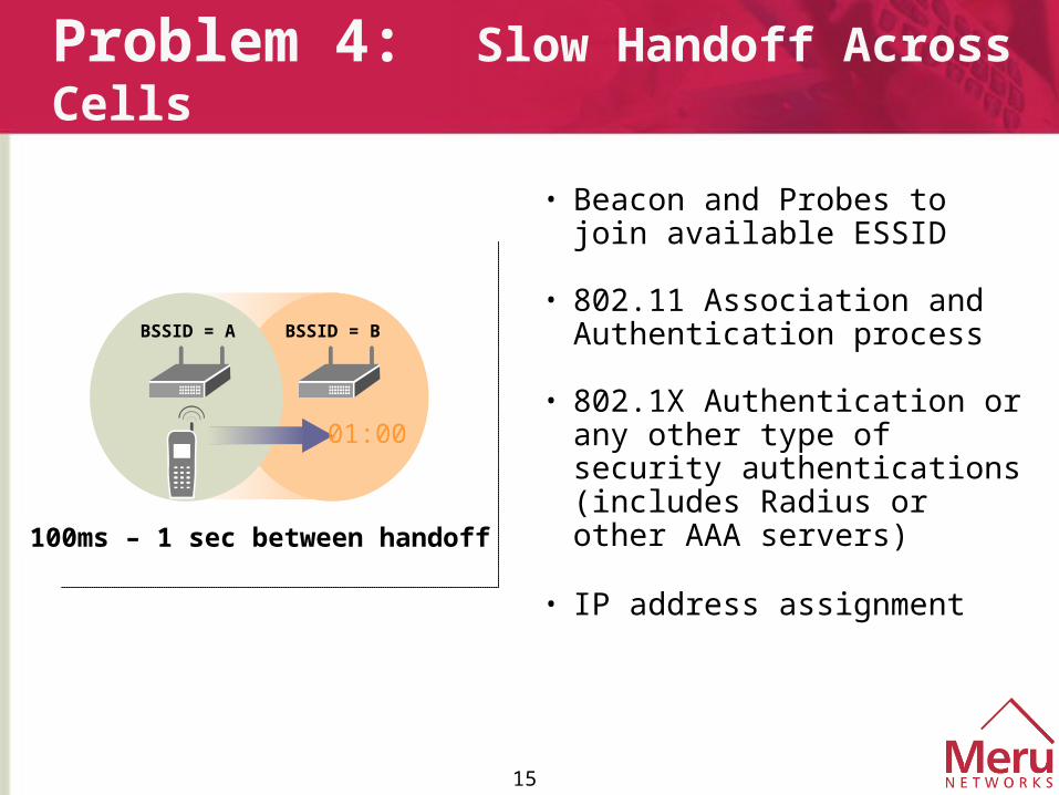
Problem 4: Slow Handoff Across Cells
• Beacon and Probes to join available ESSID
• 802.11 Association and Authentication process
• 802.1X Authentication or any other type of security authentications (includes Radius or other AAA servers)
• IP address assignment
100ms – 1 sec between handoff
BSSID = A BSSID = B
01:00
16
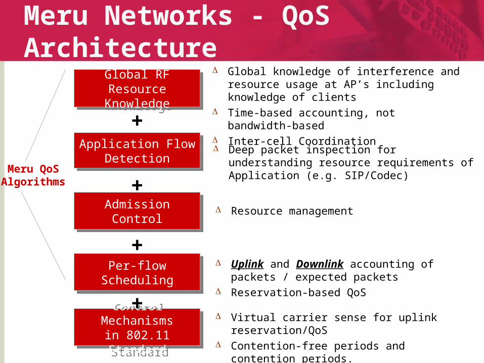
Meru Networks - QoS Architecture
Application Flow Detection
Application Flow Detection
Global RF Resource Knowledge
Global RF Resource Knowledge
Admission ControlAdmission Control
Control Mechanismsin 802.11 Standard
Control Mechanismsin 802.11 Standard
Meru QoSAlgorithms
+
Global knowledge of interference and resource usage at AP’s including knowledge of clients
Time-based accounting, not bandwidth-based Inter-cell Coordination
Deep packet inspection for understanding resource requirements of Application (e.g. SIP/Codec)
Resource management
+
+
Virtual carrier sense for uplink reservation/QoS Contention-free periods and contention periods.
Per-flow SchedulingPer-flow Scheduling Uplink and Downlink accounting of packets /
expected packets Reservation-based QoS
+

17
Meru Networks - Air Traffic Control
Centralized Control- Global Policies- Global Coordination- Central RF Intelligence- App Flow Inspection
MERU MAC- Local Governance
- Dynamic QoS Flow Recognition- Distributed Rogue Detection & Mitigation
Performed in Controller
Performed in the Access Point
ContentionManagementAlgorithms
ContentionSuppression for
QoS Flow
Virtual MACfor
Zero Handoff
VoiceClientVoiceClient
18
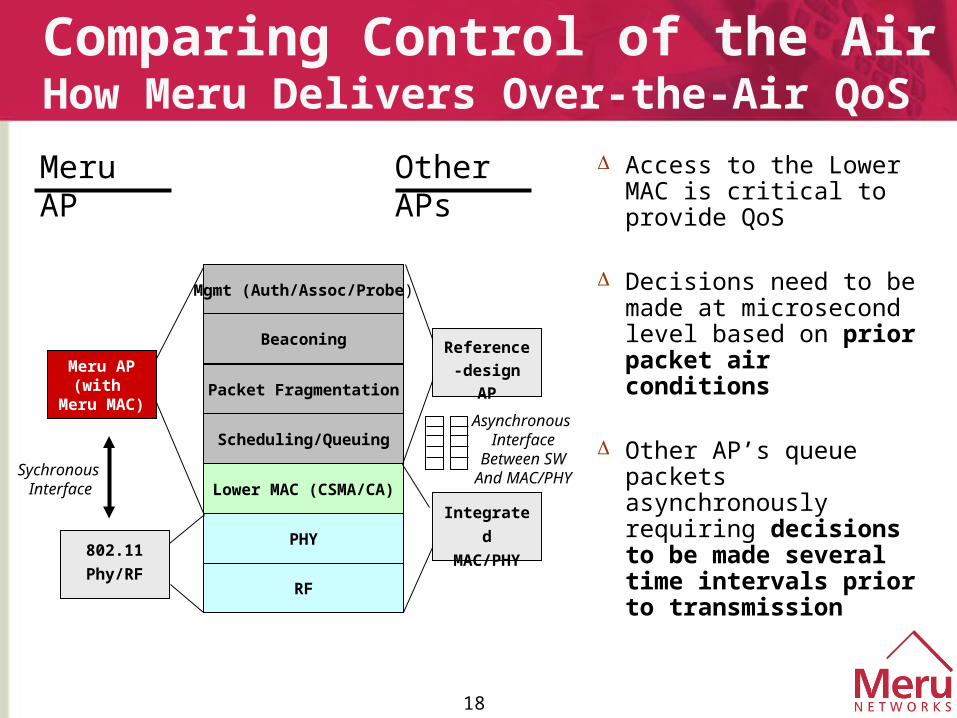
Comparing Control of the AirHow Meru Delivers Over-the-Air QoS
Mgmt (Auth/Assoc/Probe)
Beaconing
Packet Fragmentation
Scheduling/Queuing
Lower MAC (CSMA/CA)
PHY
RF
Integrated
MAC/PHY
Access to the Lower MAC is critical to provide QoS
Decisions need to be made at microsecond level based on prior packet air conditions
Other AP’s queue packets asynchronously requiring decisions to be made several time intervals prior to transmission
Reference-
design APMeru AP(with
Meru MAC)
802.11
Phy/RF
Asynchronous Interface
Between SWAnd MAC/PHYSychronous
Interface
Meru AP Other APs
19
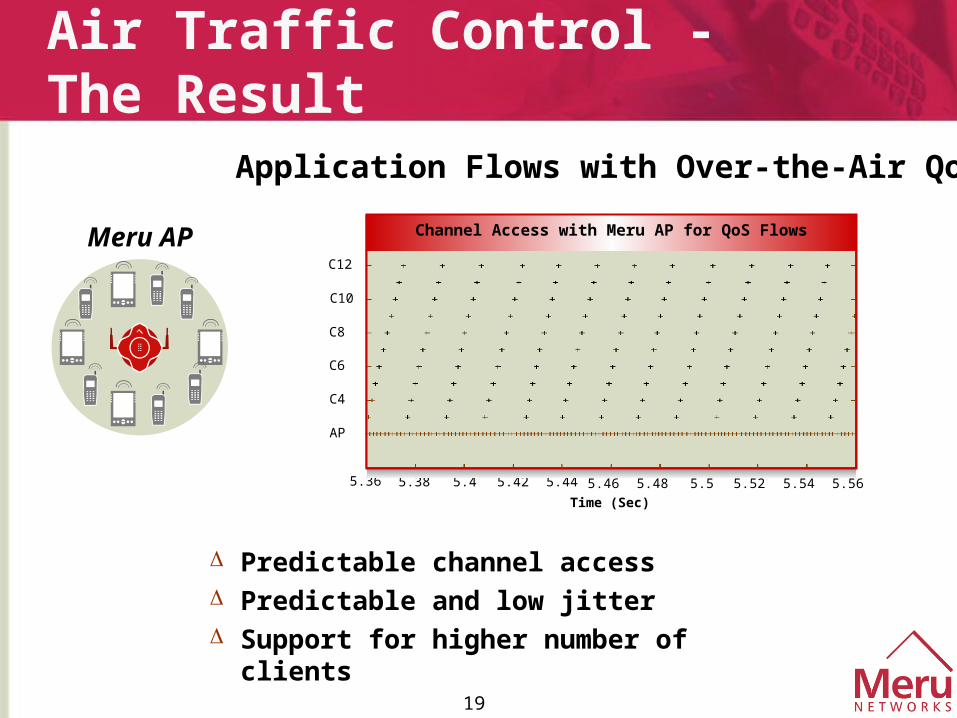
Predictable channel access Predictable and low jitter Support for higher number of clients
5.56
AP
C6
C4
C8
C10
C12
5.36 5.38 5.4 5.44 5.46 5.48 5.5 5.52 5.545.42
Channel Access with Meru AP for QoS Flows
Time (Sec)
Application Flows with Over-the-Air QoS
Air Traffic Control - The Result
Meru AP
20
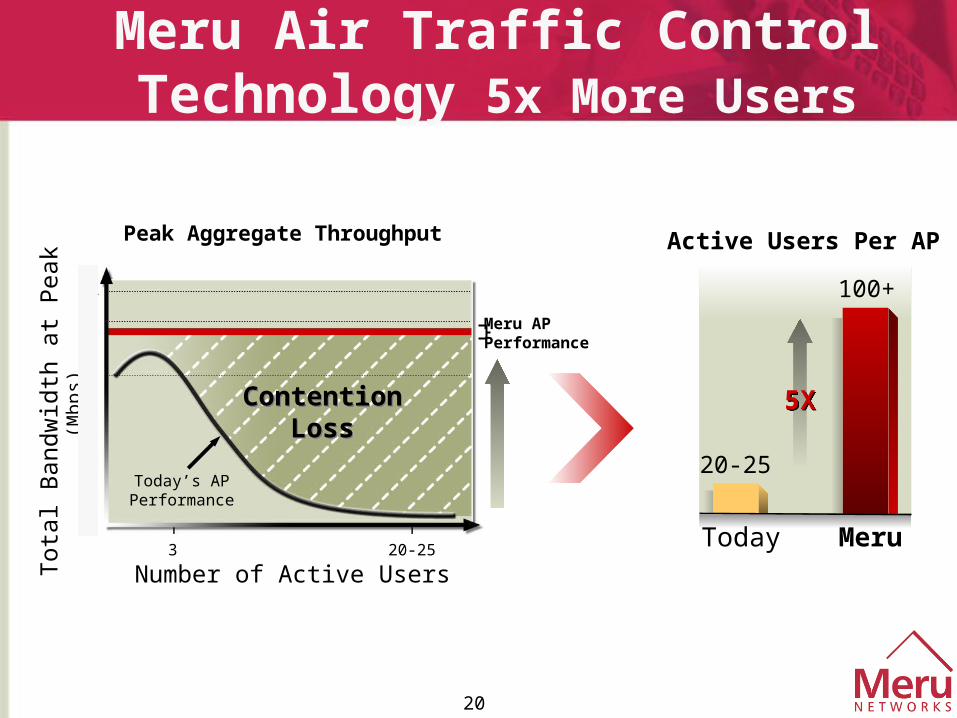
Meru Air Traffic Control Technology 5x More Users
20-25
Tot
al B
andw
idth
at
Pea
k (M
bps) 5
8
11
1
3
ContentionLoss
ContentionLoss
Today’s APPerformance
Meru AP Performance
Active Users Per AP
Today Meru
20-25
100+
5X5X
Number of Active Users
Peak Aggregate Throughput
21
Generic Access Point + Standard Client
Meru AP +Standard Client
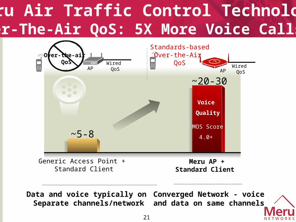
Meru Air Traffic Control Technology Over-The-Air QoS: 5X More Voice Calls
Converged Network - voiceand data on same channels
Data and voice typically on Separate channels/network
~20-30
~5-8
APWired QoS
Wired QoS
Standards-basedOver-the-Air
QoS AP
Voice
Quality
MOS Score
4.0+
Over-the-air QoS
22
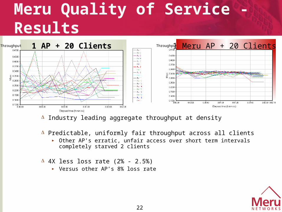
Meru Quality of Service - Results
Industry leading aggregate throughput at density
Predictable, uniformly fair throughput across all clients► Other AP’s erratic, unfair access over short term intervals completely starved 2
clients
4X less loss rate (2% - 2.5%)► Versus other AP’s 8% loss rate
Throughput 1 AP + 20 Clients Throughput 1 Meru AP + 20 Clients
23
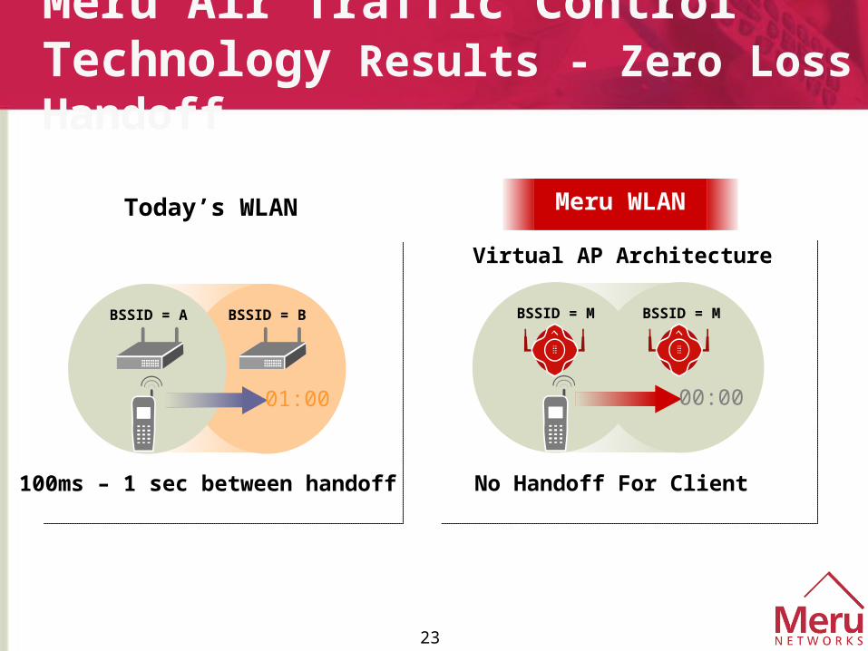
Meru Air Traffic Control Technology Results - Zero Loss Handoff
Meru WLAN
Virtual AP Architecture
No Handoff For Client
BSSID = M BSSID = M
00:00
100ms – 1 sec between handoff
Today’s WLAN
BSSID = A BSSID = B
01:00
24
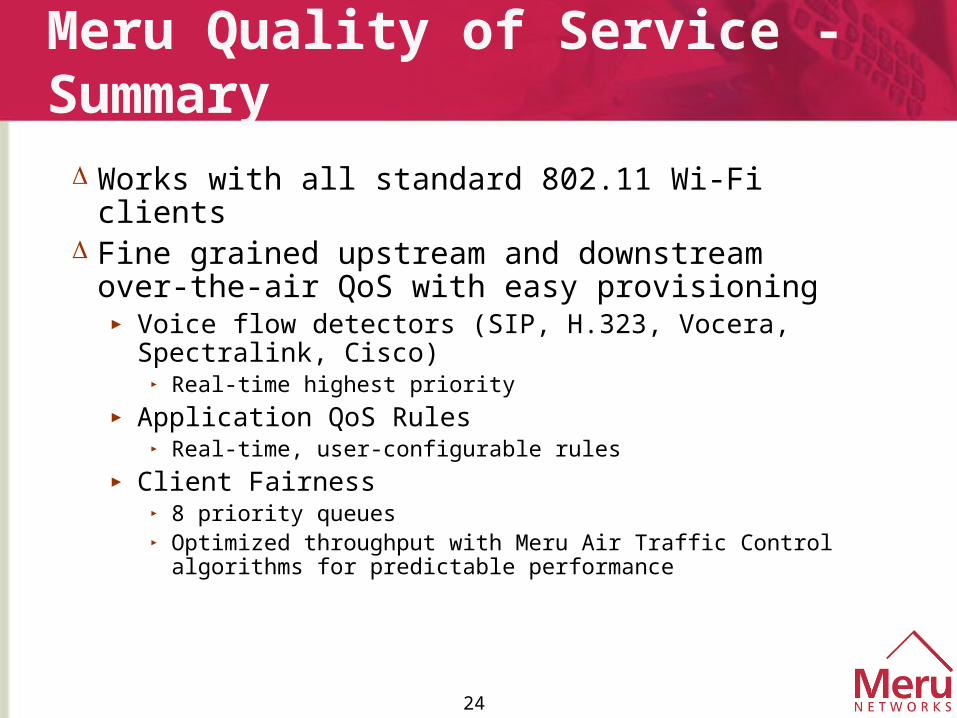
Meru Quality of Service - Summary
Works with all standard 802.11 Wi-Fi clients Fine grained upstream and downstream
over-the-air QoS with easy provisioning ► Voice flow detectors (SIP, H.323, Vocera, Spectralink,
Cisco)► Real-time highest priority
► Application QoS Rules ► Real-time, user-configurable rules
► Client Fairness► 8 priority queues► Optimized throughput with Meru Air Traffic Control algorithms
for predictable performance
25
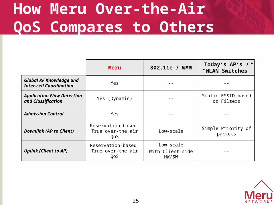
How Meru Over-the-Air QoS Compares to Others
Meru 802.11e / WMMToday’s AP’s /
“WLAN Switches”
Global RF Knowledge and Inter-cell Coordination
Yes -- --
Application Flow Detection and Classification
Yes (Dynamic) --Static ESSID-based or
Filters
Admission Control Yes -- --
Downlink (AP to Client)Reservation-based
True over-the air QoSLow-scale
Simple Priority of packets
Uplink (Client to AP)Reservation-based
True over-the air QoSLow-scale
With Client-side HW/SW--

Customer Case Study
27
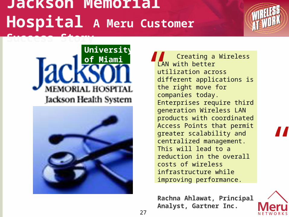
Jackson Memorial Hospital A Meru Customer Success Story
Creating a Wireless LAN with better utilization across different applications is the right move for companies today. Enterprises require third generation Wireless LAN products with coordinated Access Points that permit greater scalability and centralized management. This will lead to a reduction in the overall costs of wireless infrastructure while improving performance.
Rachna Ahlawat, Principal Analyst, Gartner Inc.
”
“ Universityof Miami
28
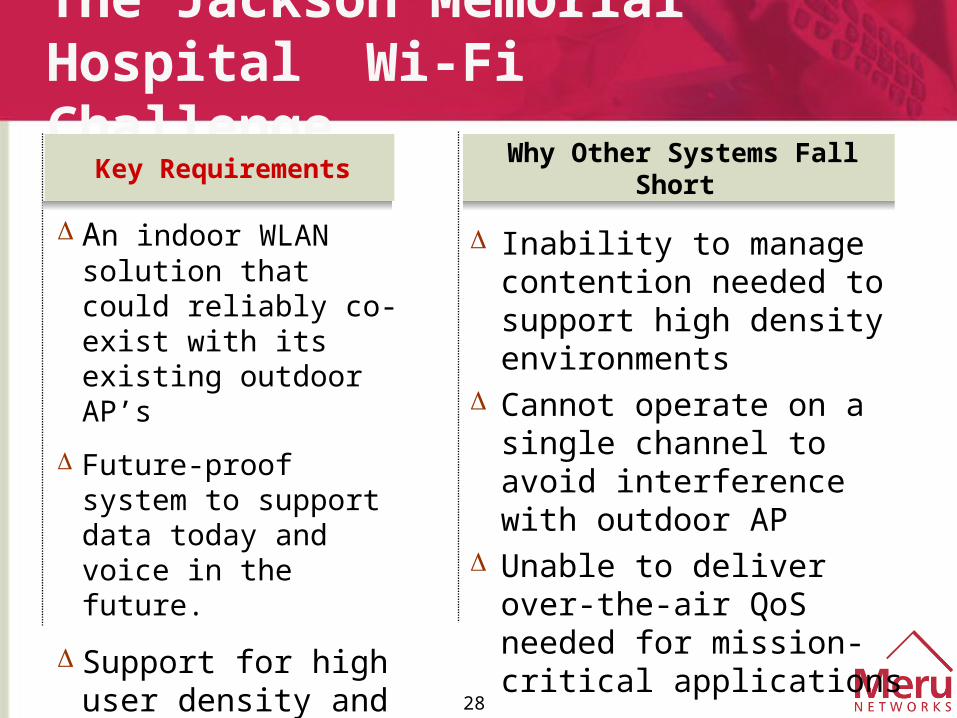
Inability to manage contention needed to support high density environments
Cannot operate on a single channel to avoid interference with outdoor AP
Unable to deliver over-the-air QoS needed for mission-critical applications
The Jackson Memorial Hospital Wi-Fi Challenge
An indoor WLAN solution that could reliably co-exist with its existing outdoor AP’s
Future-proof system to support data today and voice in the future.
Support for high user density and broad range of devices
Key RequirementsWhy Other Systems Fall
Short
29
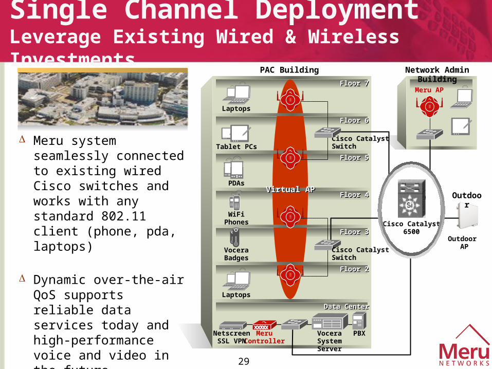
Meru system seamlessly connected to existing wired Cisco switches and works with any standard 802.11 client (phone, pda, laptops)
Dynamic over-the-air QoS supports reliable data services today and high-performance voice and video in the future
Single Channel Deployment Leverage Existing Wired & Wireless Investments
MeruController
PBXVoceraSystem Server
Data CenterData Center
NetscreenSSL VPN
Outdoor AP
Outdoor
Laptops
VoceraBadges
Cisco Catalyst6500
Virtual APVirtual AP
WiFiPhones
PDAs
Tablet PCs
Laptops
Floor 2Floor 2
Floor 3Floor 3
Floor 4Floor 4
Floor 5Floor 5
Floor 6Floor 6
Floor 7Floor 7
Cisco CatalystSwitch
PAC Building
Meru AP
Cisco CatalystSwitch
Network Admin Building

High Performance b/g Network
Co-Existence
31
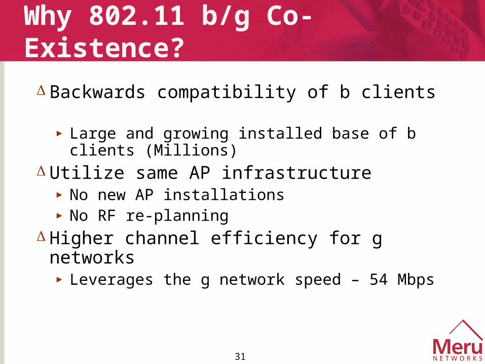
Why 802.11 b/g Co-Existence?
Backwards compatibility of b clients ► Large and growing installed base of b
clients (Millions) Utilize same AP infrastructure
► No new AP installations► No RF re-planning
Higher channel efficiency for g networks► Leverages the g network speed – 54 Mbps

32
The b/g Co-Existence Problems
Significant Co-Channel interference► Only 3 spectrally independent channels► Coverage required for high data rates
802.11b slows down g clients► g client throughput reduced by 50%+
33
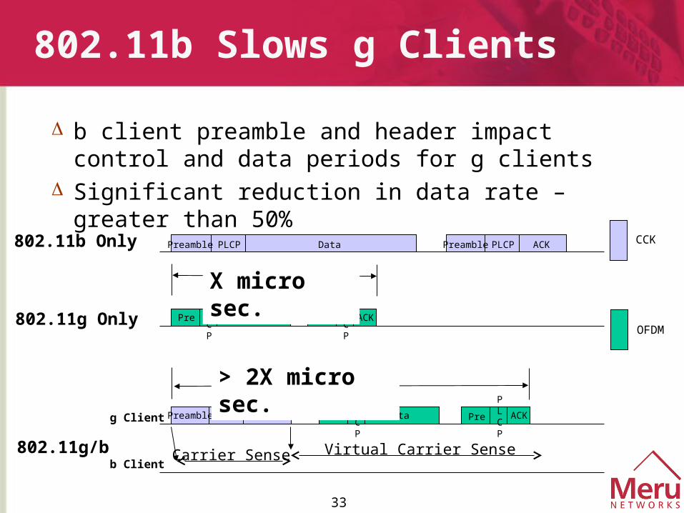
802.11b Slows g Clients
b client preamble and header impact control and data periods for g clients
Significant reduction in data rate – greater than 50%
Preamble PLCP Data ACK
CTS
Preamble PLCP
Preamble PLCP
Pre
PLCP
Data Pre
PLCP
ACK
Pre
PLCP
Data Pre
PLCP
ACK
802.11b Only
802.11g Only
802.11g/b Carrier Sense Virtual Carrier Senseb Client
g Client
CCK
OFDM
> 2X micro sec.
X micro sec.
34
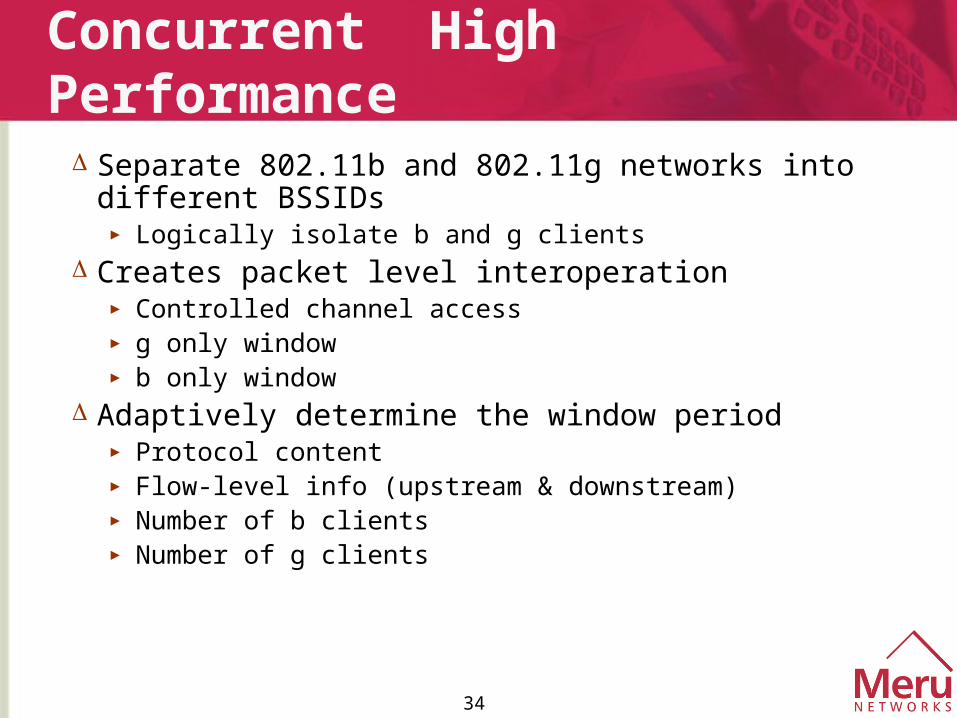
Concurrent High Performance
Separate 802.11b and 802.11g networks into different BSSIDs
► Logically isolate b and g clients Creates packet level interoperation
► Controlled channel access► g only window► b only window
Adaptively determine the window period► Protocol content► Flow-level info (upstream & downstream)► Number of b clients► Number of g clients
35
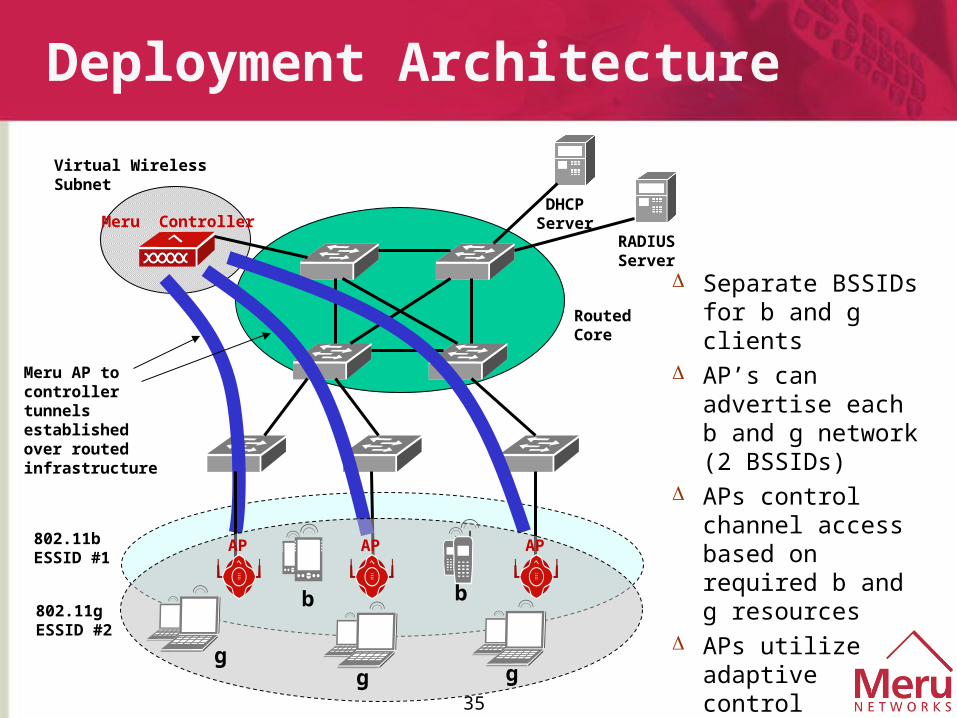
Deployment Architecture
Meru ControllerDHCP Server
RADIUS Server
Routed Core
Virtual Wireless Subnet
Meru AP to controller tunnels established over routed infrastructure
Separate BSSIDs for b and g clients
AP’s can advertise each b and g network (2 BSSIDs)
APs control channel access based on required b and g resources
APs utilize adaptive control algorithms to determine window period
AP APAP802.11b ESSID #1
802.11g ESSID #2
b b
ggg
36
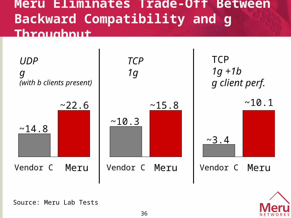
Meru Eliminates Trade-Off Between Backward Compatibility and g Throughput
UDPg (with b clients present)
~14.8
~22.6
Vendor C Meru
~10.3
~15.8
Meru
~3.4
~10.1
Meru
TCP1g
TCP1g +1bg client perf.
Source: Meru Lab Tests
Vendor C Vendor C
37
Summary
Breakthrough Air Traffic Control Technology Delivers Concurrent 802.11b and 802.11g with High Performance
► Simplify 802.11g deployment – no new APs
► Highest 802.11g throughput in mixed b/g networks
► Leverage deployed 802.11b clients
► Eliminate user performance compromise

Location Based Services
39
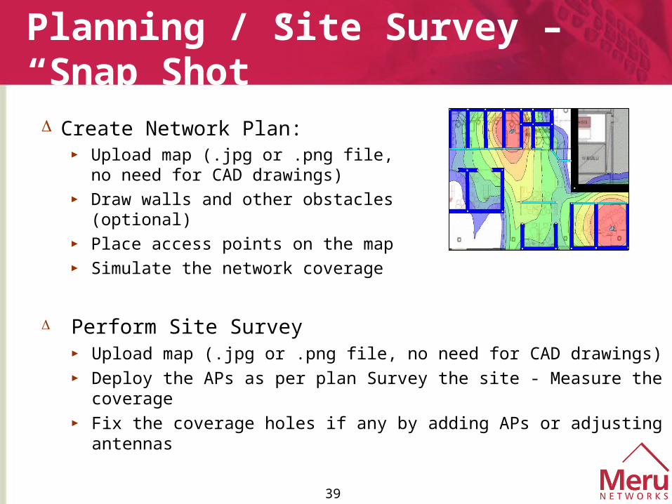
Planning / Site Survey – “Snap Shot”
Create Network Plan:► Upload map (.jpg or .png file, no
need for CAD drawings)► Draw walls and other obstacles
(optional)► Place access points on the map► Simulate the network coverage
Perform Site Survey► Upload map (.jpg or .png file, no need for CAD drawings)► Deploy the APs as per plan Survey the site - Measure the coverage► Fix the coverage holes if any by adding APs or adjusting antennas
40
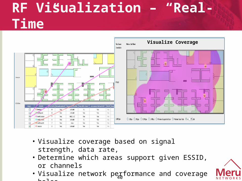
RF Visualization – “Real-Time”
• Visualize coverage based on signal strength, data rate, • Determine which areas support given ESSID, or channels• Visualize network performance and coverage holes
Visualize Coverage
41
Location Tracking Applications
Real-time location of Rogues, clients► Pinpoint rogue device (AP or client) to specific location (in a cubicle, in
the hallway, outside the building)► Allow connectivity only when client at specific location (e.g. inside
building) Real-time capacity management/troubleshooting
► Identify relevant portion of a network for capacity adjustment or troubleshooting based on caller’s location
Mobile asset tracking► Locate critical equipment or assets in hospital, manufacturing, retail
environments E-911 support
► Meet regulatory requirements for calls that require emergency dispatch
42
Location Tracking Technology
Traditional approaches:► Closest AP – find the AP that hears a signal the loudest
► Very coarse granularity (point in 60’x60’ or 3600 sq ft area)
► Triangulation – overlap coverage from 3 different APs► Granularity of ~ 30’► Challenges: Reflection, attenuation, multi-path
► RF-Fingerprinting – predict signal strength at every grid point, and match against it
► Hours of RF signature training ( ‘can you hear me now?’ approach)
► Granularity of ~10’
43
Summary
Over-the Air QoS is required for Converged WLAN networks
Breakthrough Technology Delivers Concurrent 802.11b and 802.11g with High Performance
“Stay tuned” for Location based WLAN services