Techniques in OFDM SysteIns - McGill...
81
Joint Synchronization, Channel Estintation and Decoding Techniques in OFDM SysteIns Si Li Department of Electrical and Computer Engineering McGill University Montreal, Canada October 2006 A thesis submitted to McGill University in partial fulfillment of the requirements of the degree of Master of Engineering. © 2006 Si Li
Transcript of Techniques in OFDM SysteIns - McGill...
Joint Synchronization, Channel
Estintation and Decoding
Techniques in OFDM SysteIns
Si Li
Department of Electrical and Computer Engineering McGill University Montreal, Canada
October 2006
A thesis submitted to McGill University in partial fulfillment of the requirements of the degree of Master of Engineering.
© 2006 Si Li

1+1 Library and Archives Canada
Bibliothèque et Archives Canada
Published Heritage Branch
Direction du Patrimoine de l'édition
395 Wellington Street Ottawa ON K1A ON4 Canada
395, rue Wellington Ottawa ON K1A ON4 Canada
NOTICE: The author has granted a nonexclusive license allowing Library and Archives Canada to reproduce, publish, archive, preserve, conserve, communicate to the public by telecommunication or on the Internet, loan, distribute and sell theses worldwide, for commercial or noncommercial purposes, in microform, paper, electronic and/or any other formats.
The author retains copyright ownership and moral rights in this thesis. Neither the thesis nor substantial extracts from it may be printed or otherwise reproduced without the author's permission.
ln compliance with the Canadian Privacy Act some supporting forms may have been removed from this thesis.
While these forms may be included in the document page cou nt, their removal does not represent any loss of content from the thesis.
• •• Canada
AVIS:
Your file Votre référence ISBN: 978-0-494-28606-7 Our file Notre référence ISBN: 978-0-494-28606-7
L'auteur a accordé une licence non exclusive permettant à la Bibliothèque et Archives Canada de reproduire, publier, archiver, sauvegarder, conserver, transmettre au public par télécommunication ou par l'Internet, prêter, distribuer et vendre des thèses partout dans le monde, à des fins commerciales ou autres, sur support microforme, papier, électronique et/ou autres formats.
L'auteur conserve la propriété du droit d'auteur et des droits moraux qui protège cette thèse. Ni la thèse ni des extraits substantiels de celle-ci ne doivent être imprimés ou autrement reproduits sans son autorisation.
Conformément à la loi canadienne sur la protection de la vie privée, quelques formulaires secondaires ont été enlevés de cette thèse.
Bien que ces formulaires aient inclus dans la pagination, il n'y aura aucun contenu manquant.


Abstract
Due to its high data transmission capability and robustness against multi-path
propagation, Orthogonal Frequency Division Muitiplexing (OF DM) has become
increasingly popular for both wire-Iine and wireless communications. In signal
recovery, the efficient and accurate estimation and correction of the symbol time
offset (STO), carrier frequency offset (CFO), sampling frequency offset (SFO) and
channel distortion are extremely important for the receiver to achieve good system
performance.
ln this thesis, we study and develop joint synchronization, channel estimation and
decoding schemes to provide high system performance at a relatively low complexity
for uncoded and coded OFDM systems.
We first investigate and evaluate the performance of low-complexity time-domain
joint synchronization and channel estimation scheme suitable for uncoded OFDM
systems. The proposed scheme can operate with a large initial CFO range (up to
±100% of carrier spacing). Its complexity is reduced by using a special FFT block for
time-to-frequency channel response conversion and a track-and-hold (TAH)
estimation strategy based on mid-ambles to eliminate the additional IFFT block
required by time-domain estimation.
We then consider the turbo concept to develop an iterative joint synchronization,
channel estimation and decoding scheme for coded OFDM systems operating at very
low signal-to-noise ratios (SNRs). Instead of hard decisions, the estimator uses soft
decisions of the transmitted data obtained from previous soft-input soft-output (SISO)
decoder and consequently produces better estimates of the unknown parameters.
These estimation results will then help data detector to generate more reliable soft
inputs to the decoder. The whole process will be performed in an iterative manner and
good system performance can be achieved with only a few iterations for moderate
initial synchronization errors.

,..r----
Sommaire
Grâce à sa haute capacité de transmission de données et sa résistance au phénomène
de propagation par trajets multiples, la technologie OFDM est devenue de plus en plus
populaire pour les télécommunications avec fil et sans fil. Pendant la récupération du
signal, l'estimation efficace et précise ainsi que la correction du décalage temporel de
symbole, du décalage de la fréquence porteuse, du décalage de la fréquence
d'échantillonnage et de la distorsion du canal sont extrêmement importantes pour le
récepteur afin d'aboutir à une bonne performance système.
Dans cette thèse, nous étudierons et développerons des techniques en participation de
synchronisation, d'estimation du canal et de décodage conjointes qui sont capables de
fournir une haute performance pour une complexité relativement basse pour les
systèmes OFDM.
Nous analyserons d'abord la performance des techniques conjointes de
synchronisation et d'estimation du canal à basse complexité dans le domaine temporel
pour des systèmes OFDM non-codés. Le modèle proposé peut fonctionner avec un
grand décalage initial de fréquence porteuse Gusqu'à ±lOO% de l'espacement de
fréquences porteuses). Sa complexité est réduite par l'utilisation d'un bloc FFT spécial
pour convertir la réponse temporelle du canal en réponse fréquentielle et par une
stratégie d'estimation par échantillonnage et blocage basée sur les mid-ambles pour
éliminer le bloc IFFT additionnel requis pour estimation dans le domaine temporel.
Nous considérons ensuite le modèle turbo afin de développer une procédure itérative
conjointe de synchronisation, d'estimation du canal et de décodage pour les systèmes
codés qui opérent à faibles rapports signal-sur-bruit. Au lieu d'utiliser de méthodes de
décision ferme, l'estimateur utilise des méthodes de décision quantifiée des données
obtenues du décodeur SISO précédent et, par conséquence, produit une meilleure
estimation des paramètres inconnus. Ces résultats d'estimation aideront le détecteur de
signal à générer des entrées quantifiées plus fiables au décodeur. La procédure entière
est itérative et peut offrir une bonne performance après un faible nombre d'itérations
pour les systèmes ayant un niveau modéré d'erreurs initiales de synchronisation.
ii

Acknowledgements
Pirst of ail, 1 wish to give my eamest thanks to Professor Tho Le-Ngoc who has
given me the opportunity to study at McGill University, where he guided me with the
utmost patience. Dr. Le-Ngoc has provided me with a most inspiring research
environment and has helped me through various hard times by his rich knowledge and
experiences, invaluable suggestions and firm supports. 1 also would like to
acknowledge the financial support from an NSERC/CRD Grant with InterDigital
Canada, which has enabled me to fully concentrate on the research.
1 would like to express my gratitude to ail the prof essors in the Department of
Electrical and Computer Engineering, who have taught me, particularly Prof essors
Peter Edwin Caines and Ioannis Psaromiligkos, from whom 1 have leamed a lot in
doing TA for Probability and Signal Processing 1.
Many colleagues in the Broadband Communications Lab, Jianfeng, Nestor, Robert,
Doan and Tuan have assisted me a lot and to whom 1 would like to give my sincerest
gratitude.
1 am also grateful to Prof essor Zhonglin Wang of Georgia Institute of Technology
who has encouraged me to come here and to Prof essor Hong Guo of McGill
University who has helped me especially for the settlement.
1 need to thank ail my close friends, especially Yang, Ping, Stella, Helen, Saswat,
Wengang and my roommate Na. You treat me as a family member.
My final and deepest gratitude goes to my family. 1 am forever indebted to my
parents who devote their lives to me. Special thanks go to Liang for putting me up
during the most depressive time and helping me in every aspect, especially for the
proofing of this thesis.
III

Abstract
Sommaire
Acknowledgements
Table of Contents
List of Abbreviations
List of Symbols and Notations
List of Figures
Chapter 1 Introduction
1.1 Motivations
Table of Contents
ii
iii
iv
vii
ix
xii
1
1.2 Objectives and Contributions 2
1.3 Thesis Outline 3
Chapter 2 OFDM: Basics, Synchronization and Channel Estimation 5
2.1 OFDM Basic 5
2.1.1 OFDM signal model 7
2.1.2 Guard interval and cyclic prefix 8
2.2 Channel Estimation and Synchronization Issues at OFDM Receiver 9
2.2.1 Channel estimation 10
2.2.2 Synchronization 10
2.2.2.1 Symbol timing offset 10
2.2.2.2 Carrier frequency offset and sampling frequency offset Il
2.3 Effects ofResidual Estimation Errors on OFDM System Performance 13
2.3.1 Inter-Carrier Interference (ICI) 14
2.3.1 Symbol rotation 16
2.4 Channel Estimation and Synchronization Algorithms 18
2.4.1 Channel estimation algorithms 18
2.4.2 Synchronization algorithms 19
iv

2.4.3 Joint synchronization and channel estimation algorithms
2.5 Chapter Summary
20
22
Chapter 3 Joint CFOCE-C Scheme with Reduced Complexity & Large Initial CFO
Range 24
3.1 Joint CFOCE-C Aigorithm: BriefReview 24
3.2 Low-Complexity Joint CFOCE-C Aigorithm 26
3.2.1 Reduced-complexity FFT for CIR-to-CFR conversion 27
3.2.2 Mid-amble based track-and-hold technique 28
3.2.2.1 Track-and-hold technique 28
3.2.2.2 Sequence selection 29
3.2.2.3 Performance evaluation of the track-and-hold (TAH) technique 30
3.3 Enlarging Initial CFO Range 32
3.3.1 Sequential acquisition algorithm 33
3.3.2 Joint acquisition algorithm 34
3.3.3 Simulation results 36
3.4 Chapter Summary 39
Chapter 4 Joint Turbo Synchronization, Channel Estimation and Decoding for Coded
OFDM Systems 40
4.1 Overview of the Existing "Turbo Techniques"
4.2 Transmitter Model in Coded OFDM Systems
4.3 Proposed Turbo (Iterative) Receiver in Coded OFDM Systems
4.3.1 Data Detector
4.3.2 Soft Demapper
4.3.3 SISO Decoder
4.3.4 Soft Mapper
4.3.5 Joint CFOCE-C Estimator
4.4 Simulation Results
4.5 Chapter Summary
40
45
46
47
48
49
50
50
51
56
v

Chapter 5 Conclusions
5.1 Thesis Summary
5.2 Future Work
References
57
57
58
60
vi

List of Abbreviations
Abbreviation
APP
AWGN
BER
BL
CE
CFO
Meaning
A Posteriori Probability
Additive White Gaussian Noise
Bit Error Rate
Burst Length (number of symbols per OFDM burst)
Channel EstimationlEstimator
Carrier Frequency Offset
CFOCE-C CFO, Channel Estimation and Correction Algorithm
CFOSFOCE-C CFO, SFO, Channel Estimation and Correction Aigorithm
CFR Channel Frequency Response
CIR
COFDM
CP
CRB
DD
DFE
DFT
ECC
EM
FB
FD
FFT
FIR
GI
ICI
IDFT
IFFT
UR
Channel Impulse Response
Coded OFDM
Cyclic Prefix
Cramér-Rao Bound
Decision Directed
Decision Feedback Equalizer
Discrete Fourier Transform
Error Correcting Coding
Expectation Maximization
Feedback
Frequency Domain
Fast Fourier Transform
Finite Impulse Response
Guard Interval
Inter Carrier/Channel Interference
Inverse Discrete Fourier Transform
Inverse Fast Fourier Transform
Infinite Impulse Response
vii

LLRs
LMS
LS
MAP
MIMO
MLSE
MMSE
MSE
NL-LMS
NL-RLS
OFDM
PLL
RLS
RMS
RSC
SDR
SER
SFO
SIMO
SISO
SNR
SOYA
STO
SVD
TAH
TD
2-D
Log-Likelihood Ratios
Least Mean Squares
Least Squares
Maximum A Posteriori
Multiple-Input Multiple-Output
Maximum Likelihood Sequence Estimation
Minimum Mean Squared Error
Mean Square Error
Non-linear Least Mean Squares
Non-linear Recursive Least Squares
Orthogonal Frequency Division Multiplexing
Phase-Locked Loop
Recursive Least Squares
Root Mean Square
Recursive Systematic Convolutional Code
Signal to Distortion Ratio
Symbol Error Rate
Sampling Frequency Offset
Single-Input Multiple-Output
Soft-Input Soft-Output
Signal-to-Noise Ratio
Soft Output Viterbi Aigorithm
Symbol Timing Offset
Singular Value Decomposition
Track-and-Hold
Time Domain
Two-Dimensional
viii

List of Symbols and Notations
Symbol
Am
Meaning
Complex number corresponding to mth constellation point
qth bit of the binary log2 M -tuple representing the symbol Am
A set of binary information bits
LS estimation error
A",(q)
b
c(h,i)
dq' l,k q , th coded bit before interleaver which are grouped and mapped onto
OFDM symbol Xl,k
d1k qth coded bit after interleaver which are grouped and mapped onto
OF DM symbol Xl,k
Ec Averaged energy of the individual carriers
!k Carrier frequency of the kth sub-carrier
!lI Carrier frequency offset
H Channel frequency response vector
Hk Channel frequency response at kth sub-carrier
h Channel impulse response vector
hi ith element of channel impulse response vector
hi Estimate of ith element of channel impulse response vector
Il,k CFO-introduced ICI at kth sub-carrier, lth symbol
LAPp
LLRs of a posteriori probabilities
Lg Long training symbol
Lg(i) ith sample in long training symbol
M M-QAM
N Number of sub-carriers in OFDM systems, FFT size
Ng
Length of cyclic prefix in an OFDM symbol
Ns
Totallength of an OFDM symbol including the cyclic prefix
N & Channel estimation error at kth sub-carrier, lth symbol
IX

No Noise power spectral density
R Correlation matrix of long training symbol
SNRckannel Channel SNR defined as individual OFDM carrier energy to one-sided
spectral density of additive white Oaussian noise
SNRoutput SNR at the output of the DFT for the OFDM carriers
T Sampling period
.t1T Sampling (clock) frequency offset
~ Length of the short training symbol
v Total number of channel paths
W Frequency-domain A WON noise vector
Ut/,k Frequency-domain A WON noise sample at the kth sub-carrier,
lthsymbol
w
WI,n
XI
XI,k
1
Xl
XI
XI,n
YI
1
YI
YI
Yl,n
y(i)
Time-domain A WON noise vector
Time-domain A WON noise sample at nth sub-carrier, lth symbol
Frequency-domain lth transmitted symbol
Frequency-domain transmitted sample at kth sub-carrier, lth symbol
Demodulated data at kth sub-carrier, lth symbol
Time-domain lth transmitted symbol after CP insertion
Time-domain lth transmitted symbol
Time-domain transmitted sample at nth sub-carrier, lth symbol
Estimate oftime-domain transmitted sample at thenth sub-carrier,
lth symbol
Frequency-domain lth received symbol
Frequency-domain received sample at the kth sub-carrier, lth symbol
Time-domain lth received symbol before CP removal
Time-domain lth received symbol
Time-domain received sample at the nth sub-carrier, lth symbol
Time-domain received signal at ith time instant
x

r(i,c)
()
A
B
a 2
SNR loss, defined as 'Y = SNRchannel - SN~utput (in dB)
Two dimensional correlation
Normalized carrier frequency offset, ê ~ NT f::::..j
Estimate of normalized CFO
Estimate ofnormalized CFO at thenth time instant
Symbol timing offset
Normalized sampling frequency offset, 'TJ ~ 1! Arrivai time ofthe first multi-path component
Estimate of arrivai time of the first m ulti -path component
Noise variance
Cumulative phase of the CFO
Estimate of cumulative phase of the CFO
Estimate of cumulative phase of the CFO at the n th time instant
Unknown coefficients
Estimates of unknown coefficients
Estimates ofunknown coefficients at nth time instant
XI

List of Figures
Figure 2-1 Block diagrams ofOFDM and SC-FDE 6
Figure 2-2 Output SNR versus Normalized CFO 15
Figure 2-3 SNR Loss Due to the ICI 15
Figure 2-4 SDR Due to the Phase Rotation 17
Figure 2-5 SNR Loss Due to Phase Rotation 17
Figure 2-6 BER versus SNR in the Presence of Residual CFOs 18
Figure 3-1 OFDM Receiver with Joint CFOCE-C Algorithm 26
Figure 3-2 Comparisons of Total Real Computations 28
Figure 3-3 The IEEE802.11a Preamble 30
Figure 3-4 BER versus SNR for AWGN Channel (CFO=100Hz) 31
Figure 3-5 BER versus SNR for Rayleigh Channel (CFO=100Hz) 32
Figure 3-6 BER versus SNR for Different Initial CFOs in AWGN Channel 37
Figure 3-7 CFO Estimation Variance in AWGN Channel 38
Figure 3-8 CIR Estimation Variance in AWGN Channel 38
Figure 3-9 CFO Estimation Variance in Rayleigh Channel 39
Figure 4-1 Turbo Receiver with Joint Estimation, Detection and Decoding 42
Figure 4-2 A Coded OFDM Transmitter Model 45
Figure 4-3 Turbo Receiver Using Joint Synchronization, Channel Estimation and
Decoding for COFDM 47
Figure 4-4 Joint CFOCE-C Estimator in Turbo Receiver for COFDM 51
Figure 4-5 BER versus Et/No in A WGN Channel 52
Figure 4-6 BER versus Et/No in AWGN Channel (CFO=100Hz) 53
Figure 4-7 BER versus Et/No in AWGN Channel (CFO=1000Hz) 54
Figure 4-8 CIR Variance versus Time in AWGN Channel, Initial CFO=1000Hz and
SNR=4dB 54
xii

Figure 4-9 CFO Variance versus Time in A WGN Channel, Initial CFO= 1000Hz and
SNR=4dB 55
Figure 4-10 BER versus Et/No in Rayleigh Channel 55
Figure 4-11 CIR Variance versus Time in Rayleigh channel, Initial CFO= 1000Hz and
SNR=16dB 56
xiii
Chapter 1
Introduction
1.1 Motivations
Although the history of multi-carrier modulation dated back to more than 40 years
ago, Orthogonal Frequency Division Multiplexing (OFDM) has only been extensively
exploited recently with the increasing demand for high rate broadband applications. In
OFDM, data are modulated using multiple sub-carriers so that each sub-carrier
occupies a small portion of the frequency band, hence a relatively flat portion of the
channel frequency response [1] [2]. As a result, OFDM is rather insensitive to
frequency-selective fading and requires very simple equalization. It has already been
chosen as the transmission method for many communication standards su ch as
European Digital Audio Broadcasting (DAB), Digital Video Broadcasting (DVB),
High Performance Radio Local Area Network (HIPERLAN) and 802.lla Wireless
Local Area Networks (WLAN) [3].
Performance of OFDM systems, however, is affected by the channel estimation and
synchronization including estimation and correction of the symbol time offset (STO),
carrier frequency offset (CFO) and sampling (clock) frequency offset (SFO).
Compared to single carrier systems, instead of finding an eye opening to establish the
best sampling time, estimation ofSTO for OFDM means a rough estimate ofwhere the
symbol starts. Nevertheless, it is known that OFDM performance is very sensitive to
frequency offsets, which generate inter-carrier interference (ICI) due to the loss of
orthogonality between OFDM carriers. Accurate channel estimation is also critical as it
can affect the performance of frequency-domain equalization. In burst-mode
transmission, synchronization and channel estimation can be performed either
separately or jointly. From the optimization point of view, a joint algorithm that takes
advantage of the inter-dependence between each parameter could render better
performance. Moreover, it will also allow us to approach the optimum solutions with
less overhead than separate estimation algorithms where multiple iterations between

coarse and fine estimation stages of different parameters are required.
Recently, various studies have been put into this field, the first set of which can be
viewed as semi-combined (part of synchronization parameters and channel
information) estimation algorithms by employing either iterative procedures or
exhaustive search. The more promising alternative with aIl parameters, CFO and
channel impulse response (CIR) simultaneously estimated and updated, is studied in
[33]. This joint estimation technique is later expanded to include the SFO estimation
and correction [35]. Both these two, joint CFOCE-C and CFOSFOCE-C algorithms,
offer good performance in terms of bit error rate (BER) and estimation variance at the
expense of a narrow initial CFO tracking range and high complexity.
1.2 Objectives and Contributions
The main objective of the work presented in this thesis is to study and develop joint
synchronization, channel estimation and decoding schemes which provide high system
performance at relatively low complexity for both uncoded and coded OFDM systems.
Pursuing this key objective, we first con si der uncoded OFDM systems, and examine
suitable techniques to enhance the existing CFOCE-C algorithm.
To reduce the complexity, we investigate sorne special-designed fast Fourier
transform (FFT) algorithms for time-to-frequency channel response conversion, and
develop a track-and-hold (TAH) estimation strategy based on mid-ambles to eliminate
the additional inverse fast Fourier transform (IFFT) block required by the time-domain
estimation.
To improve the performance, we propose ajoint acquisition algorithm integrated into
the CFOCE-C scheme in order to operate with a large initial CFO range (up to ±100%
of carrier spacing).
For coded OFDM systems operating at very low signal-to-noise ratios (SNRs), we
consider the turbo concept to develop an iterative joint synchronization, channel
estimation and decoding scheme which combine joint CFO and channel estimation
with soft-input soft-output (SISO) decoding. In this proposed scheme, the estimator
uses soft-decision information output from the decoder to produce better estimates of
2

the unknown parameters, which will in tum help the decoder to make more reliable
decision so that the overall system performance is improved iteratively.
1.3 Thesis Outline
Chapter 2 begins with the relevant background materials of OFDM. Two important
operations at the receiver, synchronization and channel estimation are then discussed.
The effects of residual errors after synchronization on the system performance are
analyzed. Finally, we review the studies on both sequential and parallel channel
estimation and synchronization techniques available in the literature in recent years.
Chapter 3 delineates a refined version of existing CFOCE-C algorithm [31]. It aims to
remove the disadvantageous requirements of additional FFTIIFFT blocks and the
narrow initial CFO range (of 1 % of carrier spacing) of the joint CFOCE-C algorithm.
First, a new scheme with lower complexity is presented. A track-and-hold (TAH)
technique utilizing mid-ambles is proposed to avoid the feedback IFFT block.
Furthermore, the FFT block required to compute the channel frequency response (CFR)
from the estimated channel impulse response (CIR) can be further reduced by adopting
sorne special FFT algorithms, the complexity of which is also evaluated. In the end, a
modified joint acquisition algorithm in conjunction with the CFOCE-C algorithm is
applied to operate with larger CFO range. Performance of the proposed T AH is
investigated and compared with that of the CFOCE-C for different scenarios by
simulation.
Chapter 4 extends our study to coded systems. We begin with a comprehensive
literature review of techniques based on turbo principle for both single-carrier and
multi-carrier systems, including turbo equalization and synchronization. Attributed to
this, ajoint synchronization, channel estimation and decoding scheme is then proposed,
where soft information is iteratively exchanged between the estimator and decoder to
improve the performance at different iterations. The detailed procedures and
mathematical functions are developed, analyzed and described. Simulation results
indicate that estimation errors are reduced in a progressive way by replacing the hard
decision by more reliable soft-decision information reconstructed by the SISO decoder.
Considerable performance gain in term of BER can be achieved after 4th iteration.
3

Chapter 5 concludes the thesis and suggests future research directions.
4

Chapter 2
OFDM: Basics, Synchronization and
Channel Estimation
Due to its high bandwidth efficiency and robustness against frequency-selective
fading, OF DM has become increasingly popular for both wired and wireless
communications [1 ]-[3]. This chapter covers the basic theory of an OFDM system with
a special emphasis on the channel estimation and synchronization aspects, which serves
as background knowledge for the thesis.
Section 2.1 will start with the derivations of OFDM signal and system models under
the assumption of perfect synchronization. It also discusses how to maintain
orthogonality by adding cyclic prefix (CP). Section 2.2 will address two important
aspects in OFDM receiver, synchronization and channel estimation. Section 2.3 will
investigate the effects of residual errors after synchronization on the OFDM system
performance, which can be used to select synchronization algorithms and
corresponding parameters to meet a given performance budget. An overview of
existing algorithms (sequential and parallel) for synchronization and channel
estimation will be given in section 2.4. Section 2.5 will provide a summary of this
chapter and lead to the issues to be investigated in Chapter 3.
2.1 OFDM Basic
In single-carrier transmission systems, for multimedia applications requiring very
high data rates, signal bandwidth may become larger than the channel coherence
bandwidth. Severe performance degradation in broadband single-carrier transmission
systems occurs since consecutive symbols will interfere with each other when channel
attenuation becomes frequency-selective. To improve the system performance in
presence of inter-symbol interference (ISI), different techniques such as maximum
Iikelihood sequence estimation (MLSE), linear equalization and decision-feedback
equalization (DFE), have been introduced and extensively studied in the past. MLSE is
impractically complex while low-complexity time-domain equalization for broadband
5

single-carrier transmission exhibits either large noise increase (in linear equalization)
or severe error propagation (in OFE), especially in presence of deep fades.
Furthermore, adaptive time-domain equalization for time-varying frequency-selective
fading channels becomes more difficult.
An alternative solution to de al with frequency-selective fading channels is to use
multi-carrier transmission, where seriai data stream is divided into several paraUel
sub-streams with lower rate. In this way, the bandwidth of each sub-carrier becomes
smaller as compared to the coherence bandwidth of the channel, i.e., the individual
sub-carriers experience flat fading, which allows simple frequency-domain
equalization. A special multi-carrier technique is called Orthogonal Frequency
~ivision Multiplexing (OFOM), in which carrier frequencies are selected to be
orthogonal to each other so that the spectra of the sub-carriers can be tightly overlapped
without inter-carrier-inference (ICI) in order to achieve the high spectral efficiency.
IFFT and FFT are used as an efficient method to modulate and demodulate data. In
addition, a guard interval (GI) is inserted between neighboring OFDM symbols so that
inter-symbol-interference (ISI) is completely removed as long as guard time is set to be
larger than the delay spread. Instead of using a silent period, we normally chose the
cyclic prefix (CP), which also preserves the orthogonality ofthe sub-carriers [4].
It has to be mentioned that single carrier system with frequency domain equalization
(SC-FDE) has also been regarded as one possible way to mitigate the dispersive
channel with the low complexity [5] [6]. SC-FOE inherits the similar principles of
OFOM, where a simple frequency domain one-tap equalizer can be employed to
compensate the channel effect, if cyclic prefix is properly inserted. The most notable
benefit of SC-FDE, as compared to OFDM, is its high power efficiency due to the low
SC-FDE
One Tap .. ---Î [o:::l . L-~--l DeCISion 1 ~ Equahzer'
Figure 2-1 Block diagrams of OFDM and SC-FDE
6

peak-to-average ratio. The block diagrams oftwo abovementioned systems are plotted
in Figure 2-1. It is obvious that although the overall complexity is similar, the IFFT
block is in the receiver side instead of transmitter for SC-FDE systems since data is
transmitted in time domain. That means the receiver hurden of SC-FDE is twice as
much as that of the OFDM. Besides, in fading channels, multi-carrier modulation
systems, which basically take advantage of sub-channels of relatively good
performance, can utilize different loading techniques to maximize the capacity of the
system.
2.1.1 OFDM signal model
Consider an OFDM system with N orthogonal sub-carriers, each of which is of the
form
CPk(t) = exp(j27rikt), 0::; k < N
where ft is the frequency of the kth sub-carrier. Note that suh-carriers are equally
spaced in order to make tPk (t) orthogonal during the symbol duration NT where
T denotes the sampling period.
The lth OFDM symbol, which sim ply multiplexes aIl the sub-carriers, modulated
by a maximum of N complex valuesXl,k(k = 0,1, ... , N -1), can be expressed as
#N-l #N-l Xl(t) = - L: Xl,kCPk(t) = - L: Xl,k exp(j27rfkt ).
N k=O N k=O (2.1)
It is clear that OFDM signal defined in (2.1) is in fact nothing more than the inverse
Fourier transform of N input complex valuesXl,k. The equivalent T-spaced sampled
transmitted signal can he shown as follows where the inverse discrete Fourier
transform (IDFT) is used
#N-l Xl,n = N L: Xl,k exp (j27rkn / N), 0 ::; n ::; N - 1.
k=O
Accordingly, instead ofusing the traditional matched filter, the demodulation of the
received signaIs is performed by discrete Fourier transform (DFT). This presented an
opportunity for an easy implementation of OFDM, especially with the development of
FFT which is an efficient algorithm to compute the DFT. FFT can reduce the number of
7

operations for N 2 in DFT to N log2 N , the application of which is a major
contribution to the OFDM complexity problem.
2.1.2 Guard interval and cyclic prefix
As mentioned above, in order to avoid the ISI due to the dispersive channel, a guard
interval (GI) is introduced to each OFDM symbol. If the length of the GI is larger than
that of the channel impulse response (CIR), ail the interferences are limited to GI,
which will be discarded at the receiver. Even a silent guard period could be inserted to
accomplish this job but another problem, the loss of the sub-carrier orthogonality, will
arise and further produce inter-carrier-interference (ICI). Peled and Ruizs [4] solved
this problem by introducing cyclic prefix in guard interval where, prior to each symbol,
we transmit its last few samples as weil.
The cyclic extension works as follows. Let us first represent the multi-path fading
channel through which the signal is transmitted as
v-l
hn(t) = l: Qi (t)8(n - i) i=O
where Qi (t) are the complex path gains and v is the total number of paths. Assume a
sufficiently slow time-varying channel so that, for a single burst, the channel can be
characterized by a time invariant impulse response
After cyclic prefix (with length of N g ) insertion, lth discrete transmitted OFDM
symbol can be described as follows
x~ = [XI,N-Ng, ... ,XI,N-l 1 XI,O, ... XI,N-d
= [XI,N-Ng, ... ,XI,N-l 1 Xl]
Then the lth output of the channel, with length of N + N g + v, is
where * stands for linear convolution operation and w is the time domain A WGN
noise vector.
Ignoring the first N g (remove the CP) and the last v elements and the noise, we
8

have
v-l YI,Ng = L hnX'I,Ng-n = 14JXI,O + h1XI,N-1 + ... + hv-lXI,N-(v-l)
n=O
YI,Ng+l = 14JXI,l + hlXI,O + ... + hv-lXI,N-(v-2) (2.2)
YI,N+Ng-l = 14JXI,N-l + hlXI,N-2 + ... + hv-lXI,N-l-(v-l)
From (2.2), it is easy to find out that the sequence of YNg'YNg+1,"',YN+Ng-l
now is the circular convolution of h and Xl. In fact, adding the cyclic prefix prior
to transmission and removing after reception has converted the linear convolution
operation of the channel to a circular one. Due to the property of DFT, the circular
convolution of the two signaIs is equal to the product of their DFT's. Therefore, if
Hk is kth output of N-point DFT of the channel impulse response, which can be
expressed as
[TV-l Hk = VN ~ hn exp(-j2nkn / N),O ::; k ::; N -1,
after CP removal, the kth DFT output of sequence YI can be given by
Y/,k = DFT(YI)k = DFT(XI 0 h + W)k
= DFT(Xlh . DFT(h)k + Wk
= XI,kHk + Wk
(2.3)
where @ stands for the circular convolution. That means the transmitted information
tones can be retrieved by a one-tap frequency-domain equalizer. The significance of
(2.3) is that the received waveform is sampled at the peaks ofeach of the exponential
carriers, where aIl other carrier waveforms have a zero crossing, and hence no
inter-carrier interference (ICI) occurs.
2.2 Channel Estimation and Synchronization Issues at OFDM
Receiver
One of the important issues in OFDM reception is channel estimation that determines
how much channel distortion remains to be compensated later by the equalizer.
Accurate synchronization is aiso required, which includes the estimation and
9

compensation of carrier frequency offset (CFO), sampling frequency offset (SFO) and
symbol timing offset (STO). In this section, we will present their particular challenges
and difficulties associated with channel estimation and synchronization.
2.2.1 Channel estimation
A key advantage of OFDM systems is its robustness against ISI as long as
orthogonality of the sub-carriers is preserved. If the guard interval is longer than the
channel impulse response spread, as prescribed in (2.3), frequency-domain equalizer
can be implemented by a set of complex multipliers (one for each sub-carrier), which
are the reciprocals of estimated channel attenuations. Therefore, channel estimation
plays an important role in such a system. It can be done either in frequency domain for
the sake of simplicity or in time domain for less number of parameters and possibly
better system performance. The related literature is abundant, most ofwhich belongs to
the "data-aided" approach where pilot symbols are used in estimation [1]. Pilot symbols
can be inserted into aIl ofthe sub-carriers of one OFDM symbol with a specific period,
which is normally called as "block type" arrangement or it can be inserted into part of
the sub-carriers of each OFDM symbol, which is called as "comb type" arrangement. In
the first case, channel characterization at aIl frequencies are estimated and kept until the
next pilot frame is transmitted, assuming that channel transfer function is not changing
very rapidly. In the second case, which is applied more in fast fading channel, the
receiver has only the information on pilot frequencies, thus appropriate interpolation
techniques are needed to estimate channel at the other sub-channels.
2.2.2 Synchronization
2.2.2.1 Symbol timing offset
In burst mode OFDM systems, the first task for synchronization is to correctly detect
the boundary of the OFDM burst (symbol alignment) [7].
Let ç represent the symbol timing offset in time-domain samples at the receiver. For
(-Ng + v) < ç < 0, i.e., in the ISI-free portion, the lth received time-domain
symbol YI = [YI,N+ç, ... , YI,N-I, Yl,a, Yl,l, ... , YI,NH-d is a cyclically rotated version of
the desired symbol, which results in a frequency-dependent phase rotation in frequency
10

domain due to the DFT properties, i.e.,
Yi,k = XI,kHk exp(j27rkç / N) + Wt,k.
The above equation allows the correction oftiming offsets by using a phase rotor in the
frequency domain while still preserving the orthogonality.
When ç > 0 or ç ::; (-N 9 + v), resulting in capturing a symbol outside ISI -free
range, the received symbol will then contain ISI from the adjacent symbols. Moreover,
since DFT is no longer calculated using the samples within a symbol or the CP, the ISI
will cause additional ICI [7] after demodulation.
2.2.2.2 Carrier frequency offset and sampling frequency offset
One of the disadvantages ofOFDM is its high sensitivity to frequency offsets, which
generate inter-carrier interference (ICI) due to the loss of orthogonality between
sub-carriers and thus cause severe system performance degradation [8]-[11].
Carrier frequency offset .6.f is introduced by the possible frequency difference in
the oscillators involved in up- and down-conversions in the transmitter and receiver or
the Doppler shift. CFO causes linearly varying rotation in time domain, which results in
data constellation shifted at an even rate in frequency domain
Sampling frequency offset i1T is introduced by the possible frequency difference in
sampling clocks ofthe receiver and transmitter. Similarly, SFO causes linearly varying
shift in time domain, which results in slowly drifted constellation during the burst.
Both of the CFO and SFO will destroy the orthogonality among the sub-carriers due
to the phase drift and thus cause ICI.
Define ê 1::. .6.fTN and 'fJ 1::. Ll{ as the normalized CFO and SFO with respect to
the sub-carrier bandwidth and sampling period. Then the nth received time-domain
sample of the lth OFDM symbol in the presence of both CFO and SFO can be
represented as
(2.4)
where (®}n represents the nth element of the circular convolution oftwo inputs. The
N point sequence Xl is now expressed as
11

11 ~x (. 27rkiJ (. 27rk (lN N ')J}
Xl == N 6 l,k exp JN exp JNTJ s + g + ~ i=O,l, ... ,N-l·
As usual, in equation (2.4), WI,k stands for the zero-mean, complex-valued A WGN
sample and h = [ho, ... , hu-l f is the coefficient vector of the CIR.
Under the assumption of perfect symbol timing, the received frequency-domain
samples, after removing CP, become [8]
Yi,k = Si(7rck)exp[j 7r:; (N -l)]exp[j 2;;k (lNs + Ng)]Xl,kHk +
~ . [ )] [ . 7r( m - k + cm)( N - 1) 1 [ . 27rcm ( )] H L.J sz 7r(m - k + Cm exp J N exp J~ lNs + Ng Xt,m m m=O m"",k
+Wz,k
. sin 7rck where ck = (1 + TJ)c + TJ' k and SZ(7rck) = (kl. )'
Nsin 7rC}N
The above equation shows that both of frequency offsets result in an amplitude
reduction and a phase rotation to the desired data, which further destroy the
orthogonality between sub-channels and give rise to the inter-carrier inference (ICI),
indicated by the terms with m :;:é k . As a matter offact, ifwe separately consider those
two imperfections (CFO and SFO), the distortions caused by SFO are actually
frequency-dependent. To be more precise, high-frequency tones tend ta suffer more
from SFO than do the 10w-frequency tones. Numerous studies addressed the effects of
such distortions ([9] [10] for CFO and [Il] for SFO), as will be discussed further in the
following section.
Finally, estimation algorithms can be either in frequency domain or time domain.
However, corrections or compensations for bath CFO and SFO are more preferable to
be performed in time domain. Otherwise, once the samples are converted to the
frequency domain with the DFT, any residual offsets will now appear in the received
samples and become ICI, which will not be correctable anymore.
12
2.3 Effects of Residual Estimation Errors on OF DM System
Performance
As discussed in the previous section, CFO, SFO and channel responses must be
accurately estimated and compensated before detection. IdeaIly, it is desired to obtain
exact estimation and correction of the frequency offsets so that their effects do not
degrade the performance of the OFDM receiver. However, such an ideal requirement is
impossible since any estimation has certain error due to the influence of noise and
interference. Hence, there are always sorne residual errors after synchronization, which
can degrade the OFDM system performance. In this section, we will investigate the
effects ofsuch residual errors on the OFDM system performance. We will focus on the
CFO. Our study aims to examine the behavior of residual errors and to determine the
SNR degradation due to their MSE. The results in this section can be used to select the
synchronization algorithms and corresponding parameters to meet a given performance
budget.
In steady state, after synchronization has already been established, residual errors are
very sm aIl so that their inter-dependence can be ignored. Based on this assumption, the
frequency-domain lth received OFDM symbol of the kth sub-carrier in the presence
of residual CFO can be expressed
Yz,k = Si(1ré) exp j[;; (N -1) + 2;é (lNs + Ng)]XI,kHk + Wz,k + lz,k + Nl~. (2.5)
As usual, é denotes the normalized residual CFO, Ng andN are length of cyclic
prefix and FFT, respectively and N s = N +Ng
• N/~ and Il,k represent the channel
estimation error and residual CFO-introduced ICI, both of which are normally treated
as additional noise terms.
In the first term of (2.5), the transmitted symbol Xl,k is firstly attenuated by si( 1ré)
which is very close to 1 for the sm aIl é and can therefore be neglected. Besides, it is
rotated by a time-invariant term(7Te)(N -1)/ N plus a linearly increasing component
(21ré(lNs + Ng) / N) [8]. Obviously, if there is no tracking algorithm being used,
among aIl the impairments caused by residual estimation errors, the distortion caused
by phase rotation will become the dominant factor since it grows according to the
13

number of symbols and may finally amount to unacceptable level. In the following,
system performance mainly in terms of SNR loss due to the symbol rotation and ICI
will be discussed respectively.
2.3.1 Inter-Carrier Interference (ICI)
An upper bound of the variance of the ICI for values ofCFO up to plus or minus one
halfthe carriers spacing is studied by Moose in [9], which can be expressed as follows:
A lower bound for the SNR at the output of the DFT for the OFDM carriers can also
be derived from the above equation as follows:
E {
. }2 e sm 1re
SNRoutput 2: No ;e 1 + O.5947-e {sin 1re}2
No
where channel SNR (Ee / No) is defined as
Ee _IXI,kI2 IHkI2
No - E[IWz,kI2 j
(2.6)
and Ee is the averaged received energy of the individual carriers and No is the power
spectral density.
According to equation (2.6), SNRoutput is reduced by increased CFO as shown in
Figure 2-2 for different channel SNRs. The degradation can be represented by the SNR
loss, defined as 1 = SNRchannel - SNRoutput (in dB), which is plotted in Figure 2-3.
The results indicate that the degradation due to ICI becomes more severe at high
channel SNRs for the same residual CFO.
14

0:: Z en -:::J S :::J o
30 ----- ---------~
• 1 r _._.
1 1 1 1 1
: : : : , Il
25 -\- ~- - - - e ---- ,-- ---: --- - :-- ---e - --
20 ---\-'-----1-------'--... , •• ' 1 " -.. '
'\ .. , . " . ~
15 ~'---_; .... ~ -, ~~, ...... ,' , 1
t,. " 1
l '., "
! : ., ...... :~~
Channel SNR=20dB : Channel SNR=15dB_:
Channel SNR=25dB , Channel SNR=30dB :
, , , ,
1 0 ~ - - - - -, - - - - - r-.... ~ - -, - - - - -1----1-----1----,-----1----1-----1
..... ..... .... , ..... , ,
...... , ...... , ,
5 - - - - ~ - - - - - ~ - - - - ~ - - - - :-~ .... ~ .... - Î - - - - - r - - - - 1 - - ---r-----,-----I 1 ......
o ------1-----i------..1-----i-------l-----i-------j----
1 1 1 1
_5L-----~-----L----~------~~-----L----~------L-----~----~----~ o 0.05 0.1 0.15 0.2 0.25 0.3 0.35 0.4 0.45 0.5
Normanized Carrier Frequency Offset
Figure 2-2 Output SNR versus Normalized CFO
2.5 r- - - - - - - - - - - - - - - -,
2 - - - - -1- - - - - 1 - - - - - T - - - - - ,- - . - - -, - - - - - -, - - - - - 1 - - - - - 1 - - - - - - - -,
iiI 1.5 "0
, , , _____ , _____ ~ _____ ~ _____ L _____ , ______ , _____ l _____ L_
'-" 1/)
!3 ...J
0:: Z en
, -·1- - - -
0.5 - - - - - - - -
00~---=0=.OO=1==:::0~.OO~2~~~0.~OO;3~;;;0.~OO;4~~0~.;OO;5~;;0~.OOf;6;;;;0;.OO~7;;~0~.OO~8~~0~.OO~9~~0~.01 Normalized Carrier Frequency Offset
Figure 2-3 SNR Loss Due to the ICI
15

2.3.1 Symbol rotation
The receiver normally cannot distinguish the time-invariant term
exp j [7rê(N -1)/ N] from the complex-valued channel gain and should thus be
incorporated into H k • Hence, only the term exp j[ 27rê( lN s + N g) / N] remains to be
considered. From one OFDM symbol to the next, the phase increment is given by the
angle of (27rê(Ns + N g ) / N). Assuming that the rotations are assimilated to a
distortion of power D, the expression of Signal to Distortion Ratio (SDR) was derived
by Simons [25] as follows,
1 SDR(l) = 2
1 ( . 27rd(Ns + N g )) -exp J N
1
where l den otes different instants of the burst.
The SDR due to the phase rotation caused by the residual CFO is plotted in Figure
2-4, for different burst length (length of symbols per burst) according to the above
equation. As before, SNR loss for different SNR input when l = 12 (burst length is
12) is plotted in Figure 2-5. Compared the results shown above and those in Figure 2-2
and Figure 2-3, we can conclude that the SNR loss due to the phase rotation is much
larger in comparison with that onCI. For instance, when the channel SNR is 20dB and
normalized CFO is 0.01, the SNR loss is approximately 0.25dB due to ICI while 18dB
due to phase drifts only after 12 symbols. Therefore, even a slight amount ofresidual
CFO will introduce linearly increased phase error, which quickly accumulates to an
unacceptable level with the number of OF DM symbols.
Figure 2-6 shows the BER curves for different residual CFO errors and burst lengths
(BLs). As expected, the results show that longer burst length for the same residual MSE
of the CFO produces larger degradation and the effect is more pronounced when with
residual MSE is larger. We can also conclude, from another point of view, that
feedback tracking algorithms are absolutely necessary even for relatively small burst
length in order to avoid severe BER performance loss.
16

70 - - - - -1- - - - -1- - - - -1- - - - - -1- - - - -1- - - - - -i- - - - - -1- - - - - -1- - - - - -1- - - - --1
iD ~ -1/) 0 -1
IX: Z en
20
, ----~-----~----~-
, ,
1 1 1 1
-1- _____ 1_ - - - - -l-
, , ,
-,
, - -,
- -1- _____ 1 ______ 1 ______ 1 , , ,
10 - - - - - , - - - - - , - - - -1- - - - - -1- - - - - -1- - - - --1 ,
-~---~
0.001 0.002 0.003 0.004 0.005 0.006 0.007 0.008 0.009 0.01
Normailized Carrier Frequency Offset
Figure 2-4 SDR Due to the Phase Rotation
30 -----,-----
25 _____ L _____ ' ___ _
20
15
10 - - -1 - - -
5 - -,-
, , ~
, ~---~---~---~-----~---~
0.001 0.002 0.003 0.007
Carrier Frequency Offset 0.004 0.006 0.005 0.008 0.009 0.01
Figure 2-5 SNR Loss Due to Phase Rotation
17

-1
10 ~~ ~~~~~ H~ H n n~ H ~-H ~ [nn ~-~n ~ ~-- = ~ ;-f::~i:~~=~~~t~~~-Ij - - - - - - - ., - - -- - - - - - f- - - - - - - - ., - - - - - - - f- - - - -1-- Residual MSE=1E-8,BL=12
10
-3 10
0:: w -4 al 10
-5 10
-6 10
___ ~ ________ : ________ ~ ___ . _____ : ______ i -+- Residual MSE=lE-8,BL=24
-=-==-=~~~~~~~~~~~~~~~~~~~~~~~~~~~~~~~~~~~~~~~~~~~~~=~~~ - :::: :::: :::: :::: :::: :::: =:J :::: :::: :::: :::: :::: :::: :::: :::: L :::: :::: :::: :::: :::: :::: :::: :J :::: :::: :::: :::: :::: :::: :::: :::: 1:::: :::: :::: :::: :::: :::: :::: ::::
--"--------~-------"--------~-------___ J ________ 1 _______ _
1
::::::::::::~::::::::-]::::-::::::::-- -::1--::
1 --------1-- -
1
~:::::::::::: == ~:::::::::: -=:: ~ -=.: ='=:= = -= -= = - = ~ -= ==::: - - -- -----------1----- --1------ ----1--
=- =- =- =- =- =- -=- =+ -= ::- =- -= =- -= =- =- ~ -= =- - =- =- =- =- ::; =- - -= - - - - - .- - - =- =- - =- - --1 - - - - - - - - 1- - - - - =- --------...,--------,-------..., ----- -j -- --...,- -- -1-
--------1--------1--- ----ï--------I- ------,- - -- -- - ----
---------1------ -t----------j--------I----------i--------.--------
-7 1 1 1 1 1 1 10 ~~~~~~~~~~~~~~~~~L_~~~~~~ ___ L_ _____ __
~ ~ ~ D M ~ ~ 27
SNRldB
Figure 2-6 BER versus SNR in the Presence ofResidual CFOs
2.4 Channel Estimation and Synchronization Algorithms
Synchronization and channel estimation can be performed either separately or jointly.
From the optimization point of view, a joint algorithm that takes advantage of the
inter-dependence between the parameters could render better performance. Moreover,
it will also allow us to approach the optimum solutions with less overhead than separate
algorithms where multiple iterations between coarse and fine estimation stages of
different parameters are required. In the following, we will briefly review previous
works related to both of the channel estimation and synchronization.
2.4.1 Channel estimation algorithms
With the assumption of perfect synchronization, a large number of channel
estimation algorithms can be found. Among block type pilot channel estimation
algorithms, the simplest and most commonly used is least-squares (LS) estimator [13],
where channel attenuations on each sub-carrier are obtained by dividing the received
18

training symbols by the transmitted training symbol.
If channel correlation and noise variance are known, an optimal linear channel
estimator in the minimum mean squared error (MMSE) sense can be designed by using
a two-dimensional Wiener filter [12]. To alleviate its main problem, complexity, we
could explore sub-optimal one-dimensional filter. In [13] [15], a proposed DFT-based
MMSE estimator uses channel correlation in frequency to improve the original LS
estimates of the channel attenuation. Moreover, a low-rank approximation can be
applied to further reduce the complexity. For example, in [13], the channel power is
assumed to only concentrate in a few coefficients in time domain. Later on, in [15], in
order to ameliorate the performance at high SNRs, optimal rank reduction applying
singular value decomposition (SVD) theory is used in low-rank approximation to the
MMSE estimator. To make full use of channel characteristics, a similar algorithm in
[14] also considers the channel correlation in time.
When channel is time-variant within a block, comb-typed algorithms have been
proven to be a more feasible method [16]. After the estimation ofthe channel responses
on pilot frequencies based on either LS or MMSE criteria, the channel responses on
data tones can be obtained by frequency-domain interpolation using the neighboring
pilot channel responses. High-order interpolation techniques should be expected to
produce better overall system performance. For instance, in [17], a piecewise-constant
interpolator has been shown to outperform a linear one, while a second-order
interpolation outperforms linear interpolation in [18]. In [16], the results ofusing a low
pass filter and cubic interpolation are also presented.
Most of the above mentioned algorithms could also be applied in decision-directed
mode by simply replacing known pilot symbols by decision data, which may
consequently degrade channel estimation performance due to decision feedback errors.
2.4.2 Synchronization algorithms
Assuming perfect channel knowledge, various algorithms and schemes, whichjointly
consider synchronization parameters, have also been proposed. In acquisition stage, for
example, both the S&C-type [19] [20] and VDB-type [21] methods are applied to
jointly estimate coarse CFO and STO, based on the correlation of a known data
19
sequence. The well-known S&C algorithm [19] is a simplified form of Classen' s [23]
method with extended range of the CFO, by using two training symbols with the first
one having two identical halves. Further complexity can be saved ifthe correlation after
the CFO correction is approximately real-valued, as it is for the 802.11a preamble,
discussed in [20] at the cost of sorne performance loss. On the other hand, the mean
square error (MSE) of the coarse CFO estimate for VDB [21], using the cyclic prefix
for correlation, suffers from a floor when there are coarse STO and CFO errors. The
method described in [22] eliminates such problem by shortening the correlation
window from N g (length ofcyclic prefix) to N g /4.
For long burst and variable environment, tracking is then needed in order to refine
and keep the estimates accurate. In [25]-[27], residual CFO and SFO are estimated
together. In order to avoid the non-linear problem caused by the exact modeling of the
frequency offsets in time domain, ail these tracking algorithms are frequency-domain
estimators where CFO and SFO are approximated as phase rotations. This effect will be
transformed in frequency domain as ICI, thus introduce unrecoverable system
performance degradation. More specifically, the algorithm proposed in [24] is based on
Moose's technique [9], but extended to coyer SFO. In [25], residual CFO and SFO are
obtained by applying the joint ML criterion to one or several frequency-domain
symbols. This two-dimensional optimization problem can be further linearized,
assuming coarse synchronization done. For algorithms proposed in [26][27], residual
CFO and SFO are both taken first from angle of the correlation between two
consecutive OFDM symbols and then passed to the first-order tracking loop filters. The
only difference is that algorithm in [26] is modified to use directed decision information
instead ofpilots [27].
2.4.3 Joint synchronization and channel estimation algorithms
However, the accuracy of both synchronization and channel estimation will be
adversely affected by each other. In [28], the author proved that CFO estimation has a
6dB 10ss in term ofmodified Cramér-Rao bound (CRB) without channel knowledge for
large number of sub-carriers. Unfortunately, few studies were addressed for complete
estimation problems. A joint time-domain algorithm proposed in [28] estimates
20
fractional carrier frequency offset (with the range of half of the sub-carrier space) and
channel together. The algorithm performs in an adaptive way, which first assumes that
CFO is known and will be used later on for channel estimation, then updates CFO based
on the new channel information. This procedure will be repeated until convergence is
reached. Preambles are used to obtain the coarse estimates and tracking is performed in
decision-directed (DO) feedback (FB) manner. In [29], the author proposes a method of
joint timing and channel estimation by using training symbols as specified in IEEE
802.11. A similar algorithm [30] appears later and is applied for jointly estimating the
integer part of the frequency offset and the channel based on the preamble symbol in
order to adapt to the large offsets associated with IEEE 802.16 systems. The correct
integer offset and channel are chosen by minimizing the time domain least square (LS)
channel estimation error. Another joint CFO and channel estimator based on both ML
(for frequency estimation) and LS (for channel) criteria [31], uses the pilot symbols
embedded in each OFDM symbol and also performs in an iterative manner. Although
the algorithm can work with a large CFO range and provide low estimation variance, it
requires the knowledge of the channel correlation and noise variance to get the first
estimation of CFO. Most recently, a ML technique that jointly estimates CIR, STO
and CFO in time domain, is proposed in [32] for coarse estimation. The algorithm
performs a two dimensional (2-D) search of STO and CFO to find the maximum
magnitude of CIR estimates.
AlI those semi-combined (part of synchronization parameters and channel
information) algorithms [28]-[32] are performed in time domain in order to achieve
more accurate estimates and thus less system degradation. As we have seen, the first
advantage of the time domain estimator is that it can estimate and rem ove CFO and
SFO better than a frequency-domain representation due to the irreducible ICI.
Secondly, it improves the performance by tracking fewer parameters (since the number
of CIR is always much smaller than FFT size). The accompanying drawback is that an
additional FFT block is needed to con vert CIR to a frequency response before sending
to equalization. Finally, for decision-directed mode, the effect of a decision error in a
specifie tone is redistributed over the entire time-domain symbol and thus lessened at
the expense of one additional IFFT to transform estimated symbols back to time
21

domain.
However, instead of estimating and updating ail parameters simultaneously which
means solving a non-linear optimization problem, in [28] [31], iterative procedures are
repeated several times between different parameters in order to approach the joint
optimum values while others [29][30][32] perform more like the so-called
trial-and-error method where the estimated parameters are changed in a certain step
over the who le possible range until the correct values are found. This exhaustive se arch
method can only be used for coarse estimation; otherwise an impractically large
amount of computation could be expected.
Decision-directed joint estimation schemes with CFO and CIR estimated and updated
simultaneously is studied in [33], called CFOCE-C. First-order Taylor series
approximation is used to linearize the non-linear problem and the NL-RLS algorithm
[34] is then employed. This joint estimation technique can be expanded to include SFO
estimation (CFOSFOCE-C) as weIl [35]. The suggested joint feedback
CFOCE-C/CFOSFOCE-C techniques provide an excellent performance in regard to
low estimation variance, small BER degradation and fast convergent speed. However,
the corresponding compensations are also high. First, as in any other time-domain
feedback algorithm, implementation complexity remains a problem: one additional
FFT and one IFFT are needed. Second, ifthe initial guess of the estimated parameters is
not close enough to the optimum point, linearization errors cannot he ignored and may
later on hinder prohlems for the non-linear adaptive algorithm. Stability is lost as long
as normalized CFO is larger than 0.01 in both CFOCE-C and CFOSFOCE-C
techniques. The narrow range limits their application to fine estimation or tracking
only. Both ofthese two disadvantages will be addressed and solved in Chapter 3.
2.5 Chapter Summary
To summarize, in this chapter, we first presented the basic concepts associated with
OFDM systems. Two important tasks of the OF DM reception, channel estimation and
synchronization are then described and followed by the study of the effects ofresidual
errors after synchronization on the OFDM system performance. A detailed literature
review indicates that a joint algorithm that estimates ail the unknown parameters
22

simultaneously [33] [35], can provide a good performance. The high complexity and
requirement of small initial CFO values, however, are its major disadvantages, which
we will address in the next chapter.
23

Chapter 3
Joint CFOCE-C Scheme with Reduced
Complexity & Large Initial CFO Range
The main objective of this chapter is to study and develop an enhanced version of
the joint CFOCE-C algorithm [33] with lower complexity and larger initial CFO
range. For the sake of simplicity, the effect of SFO is not included, which does not
affect the main limitations ofthe algorithm.
After a brief review of joint CFOCE-C technique in section 3.1, low-complexity
CFOCE-C (LC-CFOCE-C) algorithm is studied subsequently. In section 3.2, a special
FFT block with reduced complexity is first used to convert the estimated channel
impulse responses to frequency responses. Then, a track-and-hold (TAH) technique
utilizing mid-ambles is proposed to eliminate the additional IFFT block. Simulation
results and conclusions are given at the end. Section 3.4 discusses the modified
version of joint acquisition algorithm [28] which is used to en large the initial CFO
range for the joint CFOCE-C techniques.
3.1 Joint CFOCE-C Aigorithm: Brief Review
In this section, a NL-RLS based feedback tracking algorithm which jointly estimates
CFO and CIR will be briefly reviewed. The estimation is performed in time domain to
minimize the following least-squares cost function (averaged over M symbols)
hn 2 (3.1) M-IN-l j2n8 (IN. +N
g +n) v-l h
n =t;~YI,n-exp N ~hrXI.n_r
where Ôln = [h~, ... ,h~_l'&n] is the estimation vector of unknown coefficients at nth
time instant; input vector XI = [xl,O, ... ,xl,n, ••• ,xl,N_I] can be either the known preamble,
or the lth detected symbol. In order to simplify the above non-linear optimization
problem to a linear one, first-order Taylor series approximation is applied to estimation
24

error at nth sample and lth symbol el,n as follows:
{J( ~ n) "J( ~ n-l ) ( ~ n ~ n-l )} el,n ~ Yl,n - Xl,CO + v Xl, co co - co (3.2)
where \7 f(Xl, &n-l) is the gradient of the non-linear function with respect to the
coefficient vector estimated at the (n -l)th time instant. The modified observation
and input vector in equation (3.2) allow application oftraditional adaptive estimation
technique to obtain the cô. Using a RLS-type algorithm gives this technique the
advantage of rapid acquisition and low steady-state error.
It should also be noted that the cost function shown in equation (3.1) and (3.2)
depends on an indefinitely increasing variable. To avoid this indefinitely increase in
function gradient expressions, the argument of exponential term & is replaced by
(rp + 21!& / N) where rp is a time-varying parameter, modeling the cumulative phase
effect ofthe CFO. The updated estimate of rp at time (n + 1) is given by
(3.3)
where Jn and ên are the estimates of the phase and CFO at the n th time instant,
respectively. In steady state, the CFO will converge to its actual value, while the phase
will converge to a linearly increasing quantity. The importance of equation (3.3) is that
the estimate J grows much more slowly than t(lNs + Ng + n), and the gradient of
the exponential argument with respect to ê is independent of land n. A block
diagram of the resulting estimator is shown in Figure 3-1.
Simulation results show [33] that as long as the initial normalized CFO is less than
0.01, the CFOCE-C algorithm has a very low estimation variance and fast convergence
which ensures low BER for short bursts. In terms of system performance, as compared
to independent estimation and to joint estimation and compensation in the frequency
domain, a gain of at least 2dB over a wide range of SNR has been also observed. When
compared with ideal theoretical BER performance for 64-QAM system in A WON, the
CFOCE-C introduces less than O.ldB degradation at BER=IE-4 (SNR=24dB) for
64QAM when initial CFO is 100Hz.
The performance improvement provided by joint CFOCE-C algorithm can be
attributed to its three major properties: first, the adoption of decision feedback mode
provides the estimator with more information than pilot tones could; second, the
25

time-domain implementation reduces the number of parameters to be estimated and
models the effects of CFO precisely; furthermore, time-domain estimation error makes
the estimator robust to decision feedback errors which would otherwise degrade the
system performance.
DEMODULA TOR
ESTIMATOR
Frame By Frame Parameter Update
CP insertion and PIS IFFT
Figure 3-1 OFDM Receiver with Joint CFOCE-C Algorithm
3.2 Low-Complexity Joint CFOCE-C Algorithm
As shown in Figure 3-1, a FFT block is needed to con vert the time-domain CIR to
frequency-domain CFR before equalization. Furthermore, an additional IFFT block is
needed to transform frequency-domain detected data symbols back to time-domain
since error computation is performed in time domain.
In the following, we will investigate techniques for low-complexity joint CFOCE-C
algorithm by considering a special reduced-complexity FFT structure for CIR-to-CFR
conversion and a new track-and-hold (TAH) technique for IFFT block removal.
26

3.2.1 Reduced-complexity FFT for CIR-to-CFR conversion
As shown in Figure 3-1, the CFOCE-C algorithm performs channel estimation in
time domain and frequency responses for different sub-carriers are computed from the
estimated impulse response coefficients by using an N -point FFT. However, this FFT
block has a very sm ail number of non-zero inputs since time-domain CIR has only v
non-zero coefficients where v < < N. Therefore, existing low-complexity FFT
structures and algorithms [37]-[40] can be applied to save the computation.
"Pruning", tirst devised by Marke 1 [37] and later improved by Skinner [38], is
moditied from the standard one-buttertly radix-2 FFT. Given that the input sequence
has only L non-zero values, only the tirst L values in each group of buttertlies are
required while the others can be pruned away. If L is restricted to be a power of
two, Skinner developed a more efficient algorithm where time saving (or the total
operations saving) is accompli shed by replacing the tirst m - n stages of the FFT
computation with a simple recopying procedure where n = 10g2 Land
m = 10g2 N.
With partial transforms, Goertzel [39] produced an algorithm computing individual
FFT coefficients. For small power-of-two sets of FFT outputs, Sorensen [40]
proposed an extremely low-complexity algorithm which uses a mixture of a
Cooley-Tukey FFT [36] and a structure similar to Goertzel's algorithm.
By adopting Sorensen's algorithm, when the output size ofFFT is 512 and the input is
16,58% complexity (number ofreal operations: multiplications plus additions) can be
saved as compared with full size radix 4 algorithm, while 64% as compared with full
size radix 2 algorithm. The complexity could be further reduced when FFT size is
smaller and the number of path is less than 16, which is the largest number allowed in
IEEE802.11a.
Figure 3-2 below shows the total number of operations required to compute 64 FFT
outputs given L nonzero inputs, as a function of L. For comparison, the cost of
computing a full inverse FFT using radix 2, radix 4, split-radix FFT and of pruned
computation with Skinner's [38] and Markels's algorithms [37] appear along with that
ofSorensen's transform decomposition algorithm [40].
27

2000 1
1
1800 1 1600
1
!
~ 1400 o ~ 2i 1200
o ..... ~ 1000 Q)
oC E ~ 800
600
400
200L---------'-o 10
- --,- -- - - -- -----.------------,---
---~------ I __ ----~'--20 30 40
Number of Input Points
Radix4
Split Radix
i J
1
--~-- -~ 50 60 70
Figure 3-2 Comparisons of Total Real Computations
3.2.2 Mid-amble based track-and-hold technique
3.2.2.1 Track-and-hold technique
The CFOCE-C scheme can work in either decision-directed or data-aided mode. In
decision-directed mode, recovered (detected) data is used for estimation without
overhead, but an IFFT is needed in the feedback block since estimation is done in
time domain.
This additional IFFT could be removed by time-sharing (multiplexing) the FFT of the
demodulator but the cost offaster FFT operation might be too large. Alternatively, the
whole IFFT block can be eliminated by using time-domain mid-ambles at the cost of
overhead. Tracking (or correction updating) is performed with the known training
symbols during the mid-amble, while during the real data parts, only the correction
will be performed and the estimation will be held until next mid-amble cornes. This
track-and-hold (TAH) process will be repeated periodically for the whole burst. For
example, in IEEE802.11a, in each symbol 4 tones are assigned for pilot while 48 for
28

data. To keep the same overhead, M mid-ambles can be repeatedly inserted to every
12 x M OFDM symbols (with aIl 52 tones turn on) to update the estimation.
Considering that a shorter burst produces lower degradations for a certain residual
CFO (see Figure 2-6), a uniform distribution of 1 mid-amble for every 12 data
symbols is adopted. It is important to understand that the TAH technique is not only
limited to this particular problem. This principle can be applied to any decision-directed
feedback time-domain estimator for IFFT removal.
3.2.2.2 Sequence selection
The remaining problem is how to design a good mid-amble which can provide the
best performance. Lots of studies for the selection of training have already been done.
But most ofthe references assume either perfect channel estimation or synchronization.
ln [42], for example, the training sequence is obtained by minimizing the
corresponding variance of channel estimates for sorne specific methods. As an
alternative, designing training sequences using the CRB has been recently considered
in [43] [44]. Since the CRB provides a lower bound on the statistical variance of any
unbiased estimator, which can be asymptoticaIly achieved by the maximum-likelihood
estimator (MLE), the so-obtained sequence is not problem-dependent as above ones. In
[43], the training sequence is chosen so as to minimize the modified CRB for frequency
offset estimation in OFDM systems. A similar approach is presented in [44] for finite
impulse response channels with no frequency offset. Recently, the issues for finding
training sequences which are optimal for both frequency offset and channel estimation
are addressed by [41]. As mentioned earlier, optimal training sequences for sorne
specifie channel estimation algorithms were proposed, but no training sequence is
likely to minimize the bounds on the MSE of aIl parameters [41]. A white training
sequence (covariance matrix R equals to the identity matrix, i.e., R = 1) is proved in
[41] to possess sorne optimal properties for joint frequency offset and channel
estimation in frequency-selective channels. More precisely, it is proved that a white
training sequence minimizes the worst-case asymptotic CRB. This asymptotic CRB is
close to the exact CRB even for short data lengths, and furthermore, the direct
minimization (for a given channel) of the asymptotic CRB is shown to yield only a
minor performance gain.
29

3.2.2.3 Performance evaluation of the track-and-hold (TAH) technique
As an illustrative example, performance of the technique [33] is evaluated in
IEEE802.11a environment [3] for 64QAM in the absence of coding.
The IEEE802.l1a standard provides physical-Iayer specifications for wireless LANs
operating in the 5 GHz band. This standard defines the use of OFDM with a 64-point
FFT, where 52 tones are used to transmit data, and the remainders are set to zero to
avoid out-of-band power. Ofthese 52 tones, 4 are pilot tones used for phase tracking in
the attempts of correcting timing off sets created by sampling frequency offset. A cyclic
prefix of 16 samples is used in the standard and the sampling rate is 20Msamples/s.
In IEEE802.11a, each transmitted packet is preceded by a sequence of known
samples called preamble, whose purpose is to perform detection, synchronization and
training. It consists of 10 identical short symbols (tl-tIO shown below), each 16
samples long and 2 identical long symbols (Tl, T2), each 32 samples long and
preceded by a single cyclic prefix of 32 samples (G l 2), as shown in Figure 3-3. The
training symbols are organized so that the correlation between subsequent samples is
minimized, which improves the effectiveness of the correlation-based methods for
frequency offset and timing acquisition.
GI2 T1 T2 Data
Figure 3-3 The IEEE802.lla Preamble
For the sake of same performance comparison reference, in the evaluation of the
proposed track-and-hold (TAH) technique, we also use the IEEE802.11a structure
except one exception: instead of using 4 pilots per 52 sub-carriers in one OF DM
symbol, 1 mid-amble will be inserted per 12 OFDM symbols in order to keep the
same overhead.
As discussed in last section, no training sequence is likely to jointly minimize the
bounds on the MSE of ail parameters. However, less correlated sequence may result
in smaller asymptotic CRB. Thus, the long training symbol, which is exactly
organized to minimize the correlation among subsequent samples, is used for
30

mid-amble for the sake of both simplicity and good performance. For the
exponentially decaying Rayleigh channel used in our simulations, RMS delay spread
is set to 25ns which is a typical channel for indoor environments. SNR is defined
using the symbol energy at the transmitter, denoted Es.
Figure 3-4 and Figure 3-5 show simulation results on the BER performance
comparison of the CFOCE-C and T AH schemes in A WGN and Rayleigh fading
channels, respectively. Theoretical BER performance for 64-QAM in AWGN channel
is also given in Figure 3-4, denoted as the "ideal" case .
0:: w III
- - - - - - - -1 - - - - - - - - - - - - -1- - -- - - - - - r - - - - - - - - 1- - - - - - - - -1 - - - - - - - -
1 1 1 1 l '
.•..... , ....... ~ .... , ... ,_ .... ~.···.·.t· •• [::= ~;'~::;11 -3 1 Il! 1 1
10 = -= = = = = = ::J = = = = = = = = :r: = = = _ - =1= = -= = -= = = = :r = -= = = _ = -= -= c -= -= = = = -= -= ::J -= = -= = -= -= -= _
-4 10
: : : : : : : :1 = = = : : : : : l : : : : : _ - : : : : : : : J : : : : : : : : r: : : : : : : : :1 : : : : : : : : - - - - - - -t - - - - - - - -1- - - - - - - - -1- - - - - - --
- - - - 1 - -- - -- - - - 1- - - - - - - - -1 - - - - - - - -
- - - - - - - -1 - - - - - - - - T - - - - - - - -1- - - - - 1 - - - - - - - - 1- - - - - - - - -1 - - - - - - - -
- - - - - - - 1 - - - - - - - - 1 - - - - - - - -1- - - -
1 1 1 - - - - - - - -1 - - - - - - - - T - - - - - - - -1- - - - - - -
- - - - - - - ---i - - - - - - - - +- - - - - - - - -1- - - - - - - - -+ - --------------------------------------- - - - - - - -l - - - - - - - - +-- - - _ - - - - -1- - - - - - - - --l- - - - - - - ~ - - - - - - - -1 - - - - - - - -- - - - - - - -1 - - - - - - - - T - - - - -1- - - - - - - - 1 - - - - - - _. - - - - "1 - - - - - - - --------------._------ ------------------ - ----------------- - - - - - - - - - - - - - - - !.. - - - - - , __ 1- _______ .~ _____ _
, , - - - - - - - -1 - - - - - •. - - T - - - - - - - - - - - - - - - - 1 - - - - - - - -
_______ ~ ________ !.. ________________ ~ _______ ~ _______ 1 ______ --
1 1 1 l ' i
-5 1 1 Iii
10 ~ ~ ~ ~ ~ ~ ~ ~ ~ ~ ~ ~ ~ ~ ~ ~ ~ ~ ~ ~ ~ ~ ~ ~ ~:~ = ~ ~ = ~ = ~ ~ ~ ~ ~ = ~ ~ ~ ~:~ ~ ~ ~ ~ = : = =:: ~ ~ ~ ~ ~ ~ 1 _____ ~~ __ , ________ L_.~ ______ , __ ___ .1. ___ . __ ~
- - - - - - - _1 ________ -'-- ____ _ , ,
- - - - - - - -1- _______ -1- ________ 1 ______ _
1 1
1 ---------1-- _____ +-- _________ 1 __ ---1----------= - -= - -= ::- -= :1 - - - - - - ~ - - - - - - =- .::: .::: -=I=- .::: : -= -= : -=- - -+ -= - -= - .::: - - -!-- - - - - -= - =- -1 - . :::: = ::.: = = = ::.: =1 = = = = -= :::: -= =- L ::.: -= = = = :::: = :::: 1= -= = :: -= -= -= = :: =- - = =- =- =.::: 1= ._ = : = .. = ::: =1 = = :: = = _ : - - - - - - - -1 - - - - - - - - +- - - - - - - - -1- - - - - - - - -+ - - - - - - - - !-- - - - - - - - -1 - - - - - - -- - - - - - - ---1 - - - - - - - - t- - - - - - - - -1- - - - - - - - -+ - - - - - - - - 1- - - - - - - - -l - - - - - - -
1 1 ---.L ___ --"
20 21 22 23 24 25 26 27
SNR: Es/No (dB)
Figure 3-4 BER versus SNR for A WGN Channel (CFO=IQOHz)
Here, we assume that acquisition has already been done, which reduces the residual
CFO to 100Hz. The performance degradation of TAH method as compared to
CFOCE-C is very small for both cases. It is mainly attributed to the ICI and phase
drift caused by the residual CFO, which we cannot keep tracking and correcting
during the hold period. It is also observed that this performance degradation increases
at higher SNRs, which means the residual synchronization errors become dominant.
31

(t: W CC
-1 10 ~--~----~----~- ____ ~ -----J --~- - ,.- _ l _ ~
-2 10
- - - - - ,- - - - , - - - . - ' ~ TAH 14 - - - ~ = ~ = = - = = = = ~ -- CF~~E-C~
- __ ;. - ~ - - ~ : - - ~ - - ,~= -= = ~ ~ = = __ t ~ _ = ~ ~~I 1 1 1 1 1
, 1 1 ~ 1 -------,-----1-- -, ----T-----r-----
___ --< _____ ~ ___ .. -----+------1-----
--I====-=~=====:::r:=====I===_==!:=_===-_____ 1 ______ 1 ______ 1 ______ 1_ _ _ _ _ _ _ _.J _____ .1 _____ J. _____ 1. ____ _
1 1 ----------
1 - - - - - 1- - - - - -1- - - - - -1 - - - - - -1 - - - - - Î - - - - - ï
1 1 1 1 - - - - - 1- - - - - - 1- - - - - -1 - - - - - -1 - - - - - -1 - - - - 1 - - - -
- - - - - 1- _____ 1 _____ _
1
,
-3 1 1 1 1 1 1 1 1
10 ::: =-:::::::::c:::::::::::::::::c -= -= -= -= -=:1: -= -= -= -= :1: -= -= -= -= J -= -= -= -= -= J -= -= -= =-:::] =- =- =- =-:::: 1-=-= -= =- =- 1_ - - - - - 1- - - - - -1- - - - - -1- - - - - -1 - - - - - ---1 - - - - --t - - - - - -+ - - - - - + - - - - - + - - -- - - - - 1- - - - - - 1- - - - - -1 - - - - - -1 - - - - - ---f - - - - -1 - - - - - --t - - - -- - -t - - - - - T - - - -- - - - - 1- - - - - -1- - - - - -1- - - - - -1 - - - - - --: - - - - - --; - - - - - ï - - - - T - - - . - i - - - - -
- - - - - 1- - - - - -1- _. - - - -1- - - - - -1 - - - - - --1 - - - - - --t - - - - - -+ - - - - - -+ - - - - - + - - - - -_____ J ______ 1 ______ 1 ___ " ___ 1 ______ 1 _____ J ___ " __ J _____ l _____ l ____ _
1 1 1 1 1 1 1 1 1 _____ 1 ______ 1_ _ ___ 1 ______ 1 _____ ---> _____ -.J _____ -.l _____ 1- _____ 1- ____ _
1 1 1 1 1 1 1 1 l , 1
- - - - - 1- - - - - - 1- - - - - -: - - - - - -1 - - - - - -, - - - - - Î - - - - - 1 - - - - - T - - - - - T -
10-4 _-----'-_ 20 22 24
.L
26 28 L
30 32
SNR: Es/No (db)
, , ..l ___ __ .L
34 36
Figure 3-5 BER versus SNR for Rayleigh Channel (CFO=lQOHz)
3.3 Enlarging Initial CFO Range
As mentioned before, the joint CFOCE-C algorithm can work with either training
sequence (i.e., data-aided mode) or random data sequence (i.e., decision-directed
mode) and therefore can be used during both acquisition and tracking phases.
However, due to the non-linear effects of estimation error and the periodicity of CFO
term in the exponential function, multiple minimum points for minimizing equation
(3.1) could be expected. Therefore, the joint CFOCE-C algorithm can only work with a
limited range of initial CFO. Besides, different from conventional RLS, the effective
input of the NL-RLS is dependent on the coefficient, which makes the stability of the
algorithm depend heavily on the initial guess [33] [35]. In order to ensure convergence
from the aIl zeros, for the first long training symbol, the elements of the estimated
vector corresponding to synchronization parameters were set to zero to gain an initial
coarse estimate of the channel. Ifthe initial CFO is too large, the effective CIR over the
first long training symbol will change too quickly for RLS algorithm to track the
32

channel adequately. Due to ail these factors, the original CFOCE-C algorithm requires
a narrow initial CFO range within 1 % ofthe carrier space.
Therefore, addition al acquisition algorithms for coarse STO (timing and burst
detection) and CFO (fractional carrier frequency) estimation need to precede our fine
tracking CFOCE-C algorithm. The objective for coarse STO estimation is to roughly
detect the received burst and correct the integer timing offset of the frame's start
position. The objective for coarse CFO estimation, on the other hand, is to roughly
correct the wide range of the fractional CFO. Most of the existing fine acquisition
algorithms can narrow the range of the estimated CFO down to 1 %. We will present
two acquisition algorithms below: one is sequential and the other is parallel, both of
which are designed for IEEE802.11a.
3.3.1 Sequential acquisition algorithm
Based on [45], complete implementation of synchronizer and channel estimator can
be divided into following steps:
a) Coarse Timing Synchronization:
Since the short training sequence is designed so that its correlation is low for non-zero
delays, initial packet detection is done by passing the received signal samples through a
correlation tilter that performs the foIlowing operation:
s( m) = I: y( i)y * (i - L1)
where y(i) denotes the ith received time domain signal and ~ is the length of the
short training symbol which is 16. When s( m) goes above sorne threshold, the packet
is assumed to be detected. Accuracy ofthe initial packet detection is limited, but it gives
a rough estimate of the start ofthe preamble.
b) Carrier Frequency Offset Estimation and Correction:
Coarse frequency offset estimation and correction is performed in acquisition phase.
The advantage in having a repeated sequence in the preamble is that ail of the short
symbols suffer from same interference, except for the phase change caused by CFO. As
a result, correlation of the received samples with its delayed version should allow us for
33

the accurate estimation of the CFO, which can be obtained as follows
Ê = -J:....arg[~ y(i)y*(i - N)]. 27f i=O
It should be noted that the correlation is performed with a delayed version of the
signal itself and not the known value of the training sequence. This is because the true
timing of the packet is not yet known, and using the training sequence could result in
error.
c) Fine Timing Synchronization:
In fine timing synchronization, the received signal is correlated with long training
symbol with different values of delay which is relative to the current estimate of the
start of the packet. Only one single long training symbol is used in the correlation, and
the cyclic prefix is not used. The first delay value that maximizes the correlation over a
given search window corresponds to the proper timing.
d) Channel Estimation:
Channel estimation is done by a simple least squares approach in frequency domain
as follows (the received data sample is divided by the frequency-domain long training
sample)
3.3.2 Joint acquisition algorithm
It is c1ear that the above coarse synchronization and channel estimation require
several steps for each unknown parameter. Besides, the estimation of one parameter is
limited by the presence of another distortion. Thus, a joint algorithm is most desirable.
Similar as fine timing synchronization discussed above, a correlation-based algorithm
is proposed by Lim [32], which estimates the channel, timing and frequency offset
simultaneously in the time domain. Assuming the orthogonality among the samples,
Lim' s algorithm performs two dimensional searches of STO and CFO by maximizing
the magnitude of CIR estimates, which is the correlation between the received samples
and the long training symbol Lg (the number ofsub-carriers is assumed to be 64)
34

~ 1 i+63 _j27r êik hi = --2 Ly(i)Lg(k - i)e N
Nsa k=i
where 0'2 is the noise variance. Then, the timing and frequency offset can be extracted
from channel estimate. Lim's algorithm is much simpler than most of existing
sequential estimation techniques, su ch as [45] while with the wide CFO range (up to
±100% of carrier spacing).
The details ofthis algorithm can be explained below:
1) Correlate the ith time-domain received samples yU) with the long training
samples and vary ê from -100% to + 1 00% with a fix step size
,(i,€) = ~LgH '~'Y Nsa
= ~[Lg*{O) ... Lg*(63)l· Nsa
.27r A.
-J-êt e N
o o
o
o o .27r A(. 1) -J-ê t+
e N 0
o
o o
0 y(i)
0 y( i + 1)
0
.27r A(. 63) y{i + 63) -J-êt+
e N
2) Combine the contribution of the multi-path so that we can estimate the arriving
time for the first path correctly even though it is not the strongest path
k=i+v-l
(3(i,€) = L 1,(k,€)1 k=i
3) Search for the arrivai time of the first multi-path component ê and the frequency
offset €
{ê, Ê} = arg {max [(3 (i, Ê)]}
4) Estimate the channel coefficients accordingly
ho, ... ,hu-1 = ,(ê,€), .... ,,(ê + v -l,i)
To reduce the size the memory block and increase the search speed, the search range
of ê could be reduced down to ± 1 0%, since the coarse CFO estimate will be in that
range. If more accurate results are needed, the step size could also be reduced (at the
35

expense of search time and required memory size).
However, time-domain long training symbol cannot be regarded as uncorrelated,
which means that the channel impulse response of each path estimated by the
time-domain correlation contains not only the effective compone nt ofitselfbut also the
correlation error components coming from other paths. Modifications to Lim's CIR
estimator are derived as follows.
In case of perfect symbol timing and CFO estimation, we have
,((),E:) = c(hoRoo + h1Rol ... + hu-lRo(v-l))
,(() + I,E:) = C(hoRlO + hlRoo ... + hu-lRo(v-2)) (3.4)
where e is the arrivai time ofthe first multi-path component, v is the number of paths
and the correlation matrix R is defined as
L(v -1)L"(O) + L(v)L"(1) + ... + s(v -1 + 63)L" (63) = R(v_l)o
x(B -1)L"(O) + L(O)L"(I) + ... + L(61)L"(62) + L(62)L" (63) = ROI
x(B-(v -1»L"(O) + ... + x(63-(v-l»L"(63) = Ro(v_l)
In [32], the author assumes that in R, ail the ~j are zeros expect for i = j which
means the ith path of CIR can be directly obtained as
(3.5)
However, actual correlation components (RlO "'~Nn-l)O,Rol "'Ro(Nn-l) of the
long training sequence are non-zero and can be easily calculated in advance. More
reliable channel estimates should be expected by solving the Iinear equations set (3.4)
instead of (3.5).
3.3.3 Simulation results
In the overall structure, modified Lim's algorithm will be applied to narrow down the
range of the estimated CFO and to generate initial joint estimates of the channel and
36

timing for the tracking algorithm as the same time. Moreover, considering stability and
simplicity, NL-LMS instead ofNL-RLS is applied.
In Figure 3-6, BER performance for different initial CFOs is plotted. Results show
the necessity of additional acquisition in order to deal with large initial CFO. Even
when normalized CFO = 0.95 (CFO=300000Hz), performance curve with modified
Lim plus CFOCE-C is only 0.55dB away from the theoretical curve at BER=lE-4.
0:: w Dl
BER perfonnance for AWGN channel 10°.------.-------.-------,-------.------,-------,------,
10""
-e- Theoretical 10.6 ..... Modified Lim+CFOCE-C,CFO=300000Hz
-- Modified Lim+CFOCE-C,CFO=50000Hz ·OÔ" CFOCE-C, CFO=2000Hz •••• , CFOCE-C. CFO=5000Hz
10·7':------c:'--------'-,-------:-':---____ -'-______ -,-L-______ ,-L-____ ---'
20 21 22 23 24 25 26 27 SNR(Es/No) db
Figure 3-6 BER versus SNR for Different Initial CFOs in A WON Channel
Figure 3-7 and Figure 3-8 show the measured CFO and CIR variances (or mean
squared error, MSE) ofthe joint estimators in A WGN channels. Under moderate initial
CFO (CFO=50000Hz, i.e., normalized CFO=O.l6), residual CFO MSE is less than
lE-8 in steady-state, which corresponds to SNR loss of less than O.IdB at BER lE-4
and residual CIR MSE of less than lE-3. Similar trends for residual CFO MSE are
obtained for Rayleigh channels as shown in Figure 3-9. On the other hand, residual
MSE for CFO produced by T AH is about 2 orders of magnitude more than CFOCE-C
method and up to 3 times more pronounced for CIR. But incorporating Lim's
acquisition algorithm restricts the residual CFO MSE between 1 E-7 and lE-8 when
initial CFO is larger than 10%.
37

Q) 0 c:: (II 'C (II
> .... a -(II E ~ W
~ c:: .~
~ .... a -(II E :m w 0:: Ü
-2 10
-3 10
-4 10
-5 10
-6 10
-7 10
-8 10
-9 10
-10 10
-11 10
-12 10
-13 10
-14 10
-1 10
-2 10
-3 10
-5 10
. • \
;'-'-'-1 •. _._. __ i ~ !
-'-'i L_._._~ i
,--------,--------.-------e~
~ ~ ~
. ......... : .............. .............. ~ -•••••• ~-=: .... ... \ '--"
" -, " -, --CRLB CFO=100Hz,CFOCE-C CFO=100Hz,TAH 1
~----------------------------------------------~ _. CFO=1000Hz,CFOCE-C CFO=1000Hz,TAH i
, - CFO=50000Hz,Modified Lim+CFOCE-C[ 1- CFO=50000Hz,Modified Lim+TAH ___ J
~ -!
-~ ----'--_______ '--___ .----L ___ ~ ___ .L _____ _
2000 4000 6000 8000 10000 12000 16000 18000
Iteration Number
Figure 3-7 CFO Estimation Variance in AWGN Channel
---,-- ----,-------,---'----,-------j
1 ._._._,_._._ ...... -.-._ ..
.!'.'!!!!!'~.:.~.7..:.:.-. - • - • -- • _. -. -_. _. _. _. - • -. - • -. l \ ........... .
~ ~:L:' : ...... -..... ~~::~::::~:::~:-~::::~::::=::~:::::::::=:::~:! • •• CFO=100Hz,CFOCE-C Il J _. CFO=1 OOOHz,CFOCE -c
CFO=1 OOOHz,T AH
CFO=100Hz,TAH 1 - CFO=50000Hz,Modified Lim+CFOCE-C ---------____________ _
-6 L'===C=Fi:0==::::50::::0:::0:::0=Hiz:::,Mo=d=if:::.:ie=d::iL::::În=+=T::::A=H===-_ ------------------------10 ---L 1 1 1 -------.
2000 4000 6000 8000 10000 12000 14000 16000 1800C
Iteration Number
Figure 3-8 CIR Estimation Variance in A WGN Channel
38

-2 10 ,---------,----,-
~
-4 10
-6 10
_~ 10-6
~ o ~ -10 '-' 10
-12 10 .
-14 10
o
... _._._ .... _._ .. ; i
• ..u .. uJ'um··\uuuu ,.uuuu ........... ; ... .
\, ..... 4l.(.,.,. .. ~: •••• .:~.,' ... :~ ."..-.. ,~ .. : ~.,,-" __ • uuuuu: .-"11
"-., -.. .. ... ............................. ~....,..~:: ... . '. ' ... ......... ~~ .
:-:: g~6~1 OOHZ,CFOCE.C- - - --, J :.: g~g:~ ~~~~~~OCE-C f---------.... ____ . ____ ._________________ 1
..-.- CFO=1 OOOHz,T AH j - CFO=50000Hz,Modified Lim+CFOCE·C 1
- CFO=50000Hz,Modified Lim+TAH .
0.2 0.4 0.6 0.8 1.2 1.4
Iteration Nu mber
Figure 3-9 CFO Estimation Variance in Rayleigh Channel
1.6 1.8 2 4
X 10
3.4 Chapter Summary
In this paper, a refinement of joint CFOCE-C [33] is examined. Additional
acquisition is integrated to cope with large initial CFO. New track-and-hold technique
is proposed to remove the feedback IFFT block and a low complexity FFT algorithm
can be used to further reduce extra 58% of complexity.
39
Chapter4
Joint Turbo Synchronization,
Channel Estimation and Decoding for
Coded OFDM Systems
As explained in chapter 2, OFDM transmÏts a large number of orthogonal
narrow-bands over a broadband channel in order to mitigate the problem of ISI in
multi-path channel. In the presence of deep notches, sub-carriers may be completely
lost and the overall performance is largely affected, even though most of the
sub-carriers are detected without errors. Error correcting coding (ECC) and
interleaving are the common methods to reduce this degradation. Many error correcting
codes have been applied to OFDM, for example, convolutional codes, Reed-Solomon
codes, turbo codes and so on. It is th en natural for us to find out a way to incorporate the
synchronization and channel estimation into a coded system. In this chapter, we will
propose thus ajoint turbo (iterative) synchronization, channel estimation and decoding
scheme for coded OFDM systems.
ln Section 4.1, we will briefly review turbo techniques, including turbo
codingldecoding, equalization and synchronization first in single carrier coded
systems. A summary of related works in OFDM systems is also given. Section 4.2
presents a coded OFDM transmitter model. Based on this model, section 4.3 proposes
the structure of turbo (iterative) receiver withjoint CFOCE-C and decoding. Finally, in
section 4.4, performance results are provided and discussed.
4.1 Overview of the Existing "Turbo Techniques"
Turbo codes using parallel concatenation of two recursive systematic convolutional
codes (RSC) separated by an interleaver, were introduced in [46], along with a practical
decoding scheme. The two encoders share the same information bits, but in a permuted
order, attributed to interleaver. Instead of maximum likelihood (ML) decoding with
prohibitive complexity, the decoder iteratively computes a posteriori probability
40

(APP) with successively refined a priori information about transmitted bits. To be
more precise, the receiver consists of two soft-input soft-output (SISO) maximum a
posteriori (MAP) decoders, which accept a priori information as input and produce a
posteriori information as outputs. Decoding is performed in an iteratively way by
exchanging soft (extrinsic) values, typically in the form of log-likelihood ratios
(LLRs). These values will provide additional knowledge about the current bit obtained
through the decoding process from ail the other bits, so that preceding stages can
benefit from the information derived by following stages. Several iterations of turbo
processing can be executed to improve performance.
The performance of turbo codes can approach the Shannon limit even with very
simple RSC codes, which makes reliable communication possible at very low SNRs.
Consequently, the challenge task for receiver design is how to perform accurate
synchronization and channel estimation in such systems, especially at low SNRs.
Ideally, the receiver should jointly perform estimation, detection and decoding.
However, due to its unbearable complexity, these sub-modules are always treated
separately. At high SNRs, this will only cause little penalty when the tentative decisions
are adequately reliable. At low SNRs, however, estimating and decoding become
greatly intertwined, whose failure of either case will cause major performance
degradation. Thanks to the "turbo principle" [47] which is a general strategy of
iterative feedback decoding, one promising solution is to incorporate estimator,
detector and decoder in an iterative manner as shown in Figure 4-1. By exchanging
information between constituent components, substantial gains can be obtained as
compared to separate estimation and decoding scheme.
Although those proposed works related to the so-called "turbo techniques" differ
from each other and can be applied only for sorne specific cases, they can aIl be
summarized as follows : the reliability information from the SISO decoder is used to
improve the estimates of unknown parameters, such as synchronization or channel
knowledge; then better estimates are fed back to the detector, which will in tum provide
more reliable soft inputs to the decoder, so that the overall performance can be
improved in a progressive manner and finally converge to the optimal solution of the
joint problems.
41
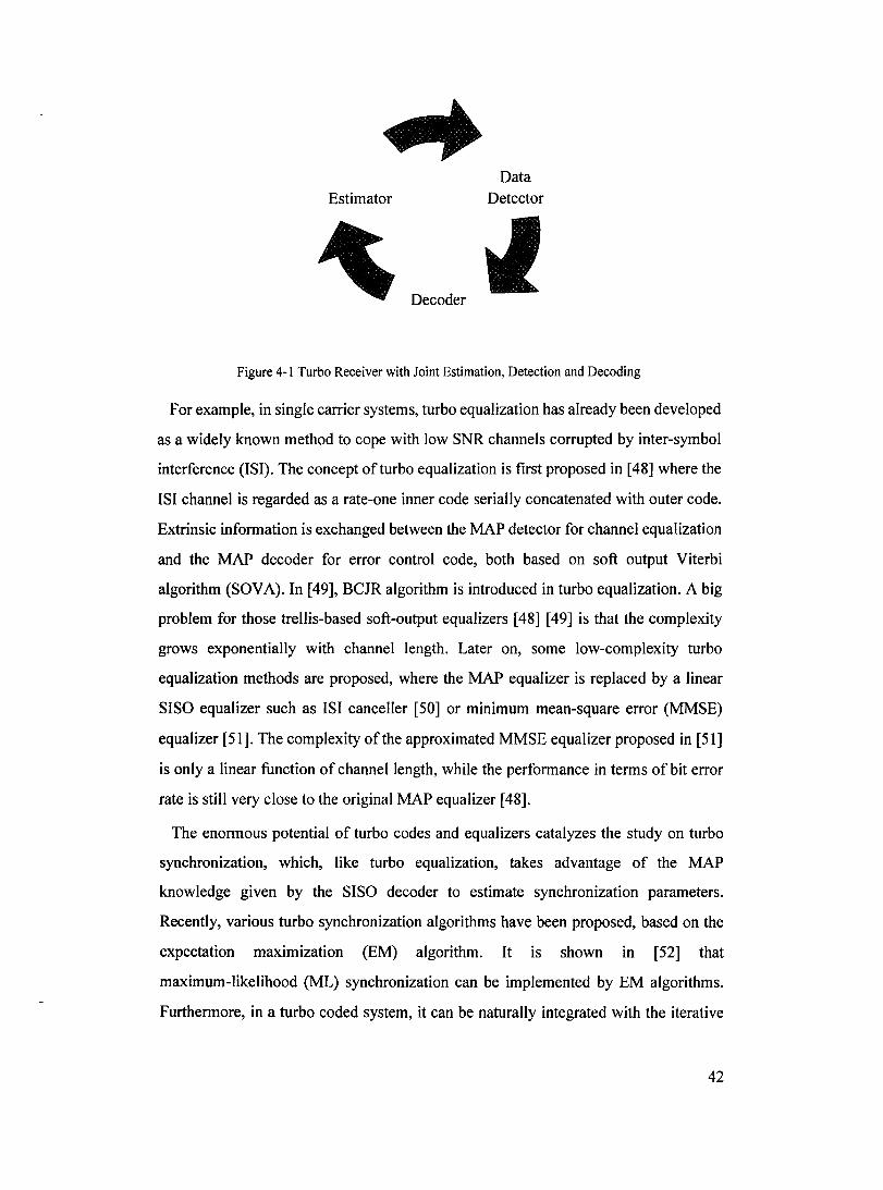
Estimator
Decoder
Data Detector
Figure 4-1 Turbo Receiver with Joint Estimation, Detection and Decoding
For example, in single carrier systems, turbo equalization has already been developed
as a widely known method to cope with low SNR channels corrupted by inter-symbol
interference (ISI). The concept of turbo equalization is tirst proposed in [48] where the
ISI channel is regarded as a rate-one inner code serially concatenated with outer code.
Extrinsic information is exchanged between the MAP detector for channel equalization
and the MAP decoder for error control code, both based on soft output Viterbi
algorithm (SOVA). In [49], BCJR algorithm is introduced in turbo equalization. A big
problem for those trellis-based soft-output equalizers [48] [49] is that the complexity
grows exponentially with channel length. Later on, sorne low-complexity turbo
equalization methods are proposed, where the MAP equalizer is replaced by a linear
SISO equalizer such as ISI canceller [50] or minimum mean-square error (MM SE)
equalizer [51]. The complexity of the approximated MMSE equalizer proposed in [51]
is only a linear function of channel length, while the performance in terms of bit error
rate is still very close to the original MAP equalizer [48].
The enormous potential of turbo codes and equalizers catalyzes the study on turbo
synchronization, which, like turbo equalization, takes advantage of the MAP
knowledge given by the SISO decoder to estimate synchronization parameters.
Recently, various turbo synchronization algorithms have been proposed, based on the
expectation maximization (EM) algorithm. It is shown in [52] that
maximum-likelihood (ML) synchronization can be implemented by EM algorithms.
Furthermore, in a turbo coded system, it can be naturally integrated with the iterative
42

decoding process since a posteriori probability provided by MAP decoder is exactly
what EM algorithms require for estimation. The author also propose to merge
synchronization iterations (EM algorithms) into decoding ones so that computation can
be greatly reduced, and simulation results show only negligible performance lost after
10 iterations. In fact, its particular application to carrier phase recovery technique has
already been reported in [53], suited for turbo coded 16-QAM systems with near
theoretical performance. Assuming perfect channel knowledge, in [54], EM-based
timing technique is proposed, which is then generalized to the multi-user case in [55].
A random walk phase offset is taken into consideration in [56], using per-survivor
processing, the idea of which is to employ the information available in the trellis to
estimate other unknown parameters. Timing recovery in ISI channel is performed,
again, by EM algorithm in [57], assuming constant timing offset within one packet.
In [58] [59], timing recovery using iterative execution of equalization,
synchronization and decoding to achieve sub-optimal solutions is considered for ISI
channels suffering from time-varying timing offsets. By embedding phase locked loop
(PLL)-based timing recovery block inside the turbo equalizer, the complexity of overall
scheme is only slightly more complex than a turbo equalizer. Simulation show a 3.5dB
gain at BER=lE-3 with a moderate random walk timing offset compared to
conventional system with separate timing recovery and turbo equalization.
We need to point out that "turbo" is not restricted to the turbo code. Other codes, for
example, low-density parity-check (LDPC) codes, or even a simple convolutional code,
can also be used as outer codes which concatenate with the estimation/detection block.
Turbo process makes use ofthe output values ofthe previous stages as a priori input for
next iteration. In this sense, ''turbo'' is almost equivalent to "iterative".
Turbo techniques have been applied to channel estimation (CE) for OFDM in both
time- and frequency- selective cases with the assumption of perfect synchronization. In
burst mode transmission, channel estimators are normally initialized based on pilots
and then iteratively updated by soft information provided by the SISO decoder from the
last iteration. Traditional CE algorithms can be integrated directly into the overall
iterative structure. The challenging part in the new scheme, however, is to not only
incorporate channel statistics in both time and frequency with low complexity, but also
43
to make use of the coded structure fully and efficiently. Simulation results in [60]
demonstrate that proposed joint channel estimation and turbo decoding method
outperforms the classical pilot-based one. The main contribution of[61] is that channel
estimation error at certain iteration is taken into account by evaluating the channel
reliability factor in case ofimperfect estimation. In [62], the complexity of2-0 MMSE
estimator is reduced by employing a separation property of channel statistics and
singular value decomposition. The probabilities of transmitted symbols are used to
improve the estimates in [63], which are proved to be a more efficient way in coding
systems. AlI the aforementioned iterative channel estimators [60]-[63] are
MMSE-based. In addition, two-dimensional APP channel estimator proposed in [64] is
realized by a concatenation of two one-dimensional estimators in time and frequency
domain, which enables iterative estimation and decoding at the receiver for lower
complexity. On the other hand, based on another criterion, EM algorithms are also
widely used for this problem. For example, in [65], where the standard statistical model
is derived from the covariance matrix for a fading channel using the Karhunen-Loeve
expansion, the EM algorithm is used to re-estimate the channel by using the soft
decisions provided by the decoder.
Blind estimations have also been studied in coded OFOM systems. In [66], instead of
first estimating the unknown parameters and then performing the data detection, a
Bayesian blind receiver without knowing channel information and CFO, derived from
[68] conceived first for COMA systems, is proposed. By applying Monte-Carlo
techniques, a posteriori probabilities of the data symbols based on the received
signaIs can be calculated by Bayesian demodulator which is followed by a MAP
channel decoder. The Bayesian turbo receiver iteratively exchanges the extrinsic
information of data symbols between the Bayesian demodulator and MAP decoder. It
requires knowledge of the specifie probability distributions of data symbols,
multi-path, and CFO, which is quite computationally intensive. A blind technique
proposed in [67] for single-input multiple output (SIMO) antenna systems, which can
be extended to MIMO systems, requires more receive antennas than transmit antennas
and that the received signaIs measured off the multiple receive antennas are subject to
independent fading.
44

Unfortunately, up to now, existing turbo (iterative) structures in coded OFDM
systems aim mainly for time-varying frequency-selective channel estimation.
However, receiver designs featuring only frequency selective fading channels without
the assumption of perfect synchronization, which are widely encountered, should also
be treated. For example, when systems operate in a slow fading channel as in most of
the indoor environment, we do not need to consider time varying channel
characteristics if burst length is short. Moreover, due to the delay and complexity of
decoding, smaller burst length is in fact more practical and preferable. In the
following, we will focus therefore on turbo receiver for joint synchronization and
channel estimation in coded OFDM systems within a short burst. The joint CFOCE-C
algorithm will still be utilized, but in order to make use ofthe coded structure, soft data
decisions will be used instead ofhard decisions as the input ofthe estimator.
4.2 Transmitfer Madel in Coded OFDM Systems
Figure 4-2 shows the transmitter model of coded OFDM systems.
li A~l>bse
Figure 4-2 A Coded OFDM Transmitter Mode)
Consider a set ofbinary data b passing into the encoder. We assume M-QAM as the
modulation format and use Q denoting for the number of bits per symbol
(Q = log2 M). Then, after interleaver, symbol mapper will group and map Q bits
d/\ (q E 0,1, .. ', Q -1) onto a complex symbol X/,k = Am where l, k denote the
OFDM symbol and sub-carrier index, respectively and Arn is the mth complex
number drawn from constellation points. Then, each symbol will be modulated by
N sinusoidal sub-carriers using the IFFT:
1 N-l
x/,n = N L X/,k exp(j27rknj N); n = 0,1, ... , N - 1 . k=O
45

In the receiver, oscillator frequency errors or channel-induced Doppler shifts will
cause the received signal to be modulated onto a carrier frequency with offset é. Then
time-domain received signal, after discarding the cyclic prefix, can then be expressed
as
where Hk is the channel gain at the kth tone and WZ,n represents the additive white
noise as before.
4.3 Proposed Turbo (Iterative) Receiver in Coded OF DM
Systems
In this section, we will present a jointly iterative synchronization-channel and
decoding estimation scheme for coded OFDM systems as illustrated in Figure 4-3.
The proposed turbo receiver structure iterates between data detector, joint CFOCE-C
estimator, soft mapper/demapper and SISO decoder sub-modules as follows.
At first, the data detector compensates the effects of both channel distortion and
CFO and delivers the demodulated data XZ,k. Immediately after, reliabilities of the
coded bits will be computed in soft demapper, used as the soft inputs to the SISO
decoder. Next, a posteriori probabilities of the coded bits outputted by the SISO
decoder are re-interleaved, the LLRs of which are sent to soft mapper in order to
produce the soft estimates of transmitted data XZ,k. At the same time, the difference
between the interleaved LLRs and the reliability values of the coded bits (produced by
the Soft Demapper) is feed back to soft demapper, treated as the input a priori
information. Finally, given the received signal 71,n and the estimates of transmitted
signal Xl,n, both in time-domain, the CFOCE-C estimator will feed the estimates of
both the CIR and CFO back to data detector. Initially, since only theXz,k is available,
joint estimator can only use the hard-decision XZ,n derived directly from XZ,k by
IFFT. However, when the soft mapper outputs, i.e., the soft estimates of the XZ,k, are
available, they are used to provide E[x/,nl as input to the joint CFOCE-C estimator
for computing CFO and CIR, which are then employed by the Data Detector for the
46

next iteration.
//~----------------- .~
/ Data Detector
Joint CFOCE
Estimator
Figure 4-3 Turbo Receiver Using Joint Synchronization, Channel Estimation and Decoding for COFDM
It can be seen that the above-mentioned turbo receiver operates in an iterative
manner over a block of coded bits with a length equivalent to the number of bits per
burst. De-interleaver between the soft demapper and SISO decoder, and interleaver
between the SISO decoder and soft mapper, corresponding to the interleaver used in
the transmitter, are used to break the data correlation. In the following, together with
the Figure 4-3, functions of each sub-module in the ab ove process will be detailed.
4.3.1 Data Detector
ln the receiver, data detector performs CFO removal, demodulation (FFT) and
frequency-domain equalization. Given the estimates updated at the beginning of each
OFDM symbol, CFO will be compensated by time-domain rotation to establish
synchronization as follows
Under the assumption of perfect synchronization, after demodulation, transmitted
information tones can be retrieved by a one-tap equalizer, i.e.,
47

where
4.3.2 Soft Demapper
The objective of the soft demapper is to calculate the LLRs of conditional
probabilities on the coded bits, namely, extrinsÏc channel information to be used by the
SISO decoder. Assuming perfect CFO removal, extrinsic channel LLRs for bit
d?k (q E 0,1,.· .,Q -1) can be obtained from the observed XZ,k and estimates of B"k as follows:
q _ q Pr(Xz,kIÊü;d~k = 1) Lext ( dz,k) = L ( XZ,k 1 dZ,k) = log (- 1 ~ )
Pr XZ,k HZ,k; d~k = 0
1 Pr (XZ,k Ibz,k;[ dfk"'" d~k = 1,'" d~k-l ]) . Pr ([ dfk'''' dZ~k = 1,'" d~k-l ]) = og Pr(Xz,kIÎlz,k;[d~k, ... ,dz~k = O, ... d~k-l]). Pr([dz~k, .. ·d~k = O, ... d~k-l]) (4.1)
L:: Pr ( XZ,k 1 Îll,k ; XZ,k = Am) . Pr( XZ,k = Am) Arn:d'lk=l
=log--=='----~~~--------_,-----------L:: Pr(Xz,kIÎlz,k;Xz,k = Am)' Pr(Xz,k = Am) Arn:dlk=O
where the notation Am: d':k = 1(0) represents the set of constellation point that
corresponds to d':k = 1(0).
Consider the transmitter model III Figure 4-2, the first term
Pr (XZ,k Ibz,k; XZ,k = Am) in equation (4.1) can be simply calculated as
Owing to the interleaver between the encoder and symbol mapper, the coded bits dik can be regarded as being independent to each other. Thus, the second term, joint
probabilities can be written as follows:
48

Pr(X"k =Am)=Pr(d'~k = Am(O), ... ,dfk-1 =~(Q-l») Q-l
= Il Pr (d':k = ~ (q) ) q=O
where ~(q) denotes the qth bit ofthe binary logz M - tuple representing the symbol
~, m = 0, 1,2,. ", M -1 .
Let's take a specifie modulation scheme, 4-QAM (M=4, Q=2) for instance, as the
illustration of the above calculation. The extrinsic channel LLRs for first coded bits of
Q successive ones can be calculated by
=log pr( XI,kJiII,ki[d~k =l,dtk ])-Pr([d~k =l,dtk ])
pr( XI,kJiII,k i[ d~k =O,df,k ]} pr([ d~k =O,df,k ])
( - J" [0 1 ]) (1 ) (- J" [0 1 ]) (1 ) (4.2) =log Pr XI,k Ht,ki dt,k=l,dt,k =1 ·Pr dt,k=l +Pr Xt,k Ht,kj dt,k=l,dt,k =0 ·Pr dt,k=O
pr( Xt,kJiIt,ki[d~k =o,dl,k =l]).pr( df,k =1 )+Pr( Xt,kJiIt,k i[d~k =O,dtk =o]).pr( dl,k =0)
pr( Xl,k JiII,k jXI,k =A2 )+ pr( XI,k JiII,k jXI,k =.43 ).exp La (df,k)
= log pr( XI,kJiII,k jXI,k =Ao )+pr( XI,kJiIt,kiXI,k =A1 )-exp La dtk
Similarly, the extrinsic channel LLRs of second coded bits are
Lext (dt,k) = L (Xt,kl dt,k) = L (X/,kl H/,k;dt,k)
= 10 Pr (Xl,k 1 H/,k; Xl,k = AJ) + Pr (X/,k 1 Ht,k; Xt,k = Al) . exp La (dt~k) (4.3)
g Pr ( X/,k 1 H/,k ; X/,k = A2) + Pr ( X/,k 1 Ht,k ; X/,k = Ao) . exp La ( d/~k ) As shown in equations (4.2)(4.3), a priori knowledge of coded bit is needed for
accurately calculating the extrinsic channel information. Similar as turbo iterative
decoding, a priori Log-Values La (d(k) can be obtained by subtracting the
corresponding LLRs of the conditional probabilities Lcxt(dt~k) from the LLRs oftheir
a posteriori probabilities LAPP (d1k) [69].
4.3.3 SISO Decoder
Given the soft values Lext (d(k) provided by soft demapper, after de-interleaving,
49

the LLRs of a posteriori probabilities on coded bits LAPP(dl:~) can be obtained by
performing BCJR algorithm. Consequently, the probabilities of the coded bits, which
will then use to reconstruct the transmitted symbols, can be calculated as
4.3.4 Soft Mapper
In the Soft Mapper, the output of SISO decoder is re-interleaved and re-mapped in
order to obtain more reliable estimates of the transmitted symbols, which can be
expressed as
E[Xl,k] = L Xl,kP(Xl,k = Am) XI,k=Am
where
4.3.5 Joint CFOCE-C Estimator
In original joint CFOCE-C algorithm, we attempt to minimize the LS cost function by
applying the NL-RLS. A veraging over M symbols, the cost function can be
expressed as
M-IN-l
c(lÎ,t) = L L lel,kl2
1=0 k=O
~l~ j2nt(lNs +Ng +k)~i: A 2 = D D rz,k - exp N D ,,,,,Xl,n-r
l=O k=O r=O
(4.4)
where rz,k is the time domain received signal, and Xl,n denotes the hard decision of
the transmitted signal Xl,k, land k are the symbol and sample index, respectively.
50

As evident from equation (4.4), c(lÎ., g) is a nonlinear function of g, and thus the
solution is difficult to find. One approximation approach is to use the first-order Taylor
series to convert this non-linear estimation error into an approximate linear-function
and then NL-RLS algorithm is applied. It is also indicated in (4.4) that the
performance of joint CFOCE-C algorithm actually depends on the decision reliability
of Xl k. Thus, it is natural for us to use the soft information from the output of the ,
decoder in estimation to reduce decision feedback errors, i.e., better performance
should be expected by replacing the hard-decision ia,n by more and more reliable
soft-decision E[xl,nl which is iteratively updated by the SISO decoder.
Nevertheless, in order to minimize the decoding and interleaver delay, in the first
iteration, joint CFOCE-C algorithm will initially operate with hard-decision Xl,n and
then with E[xI,nl as soon as it is available. Figure 4-4 shows the structure of the
modified joint CFO-CE estimator.
Xt,n / E [Xl,n]
edback Time domain fe
hard/soft decisi on
'T'l,n
Received Time domain signal
1
A
fT\ RLS
h,Ê -"" V Aigorithm
Figure 4-4 Joint CFOCE-C Estimator in Turbo Receiver for COFDM
4.4 Simulation Results
Simulations are performed in the IEEE802.11a environment for 4-QAM. Same as in
chapter 3, this standard specifies the use of OFDM with an FFT size of 64, on which 52
tones are used to transmit data, and the remainder of the tones is set to zero to avoid
out-of-band power. A cyclic prefix of 16 samples is used in the standard and the
sampling rate is 20Msamples/sec. Every burst consists of21 OFDM data symbols and 2
long training symbols used for initialization in each transmit burst. As an illustrative
51

example, the rate-1I2 RSC code with generator matrix equal to [1 1 1 1 0 1] is used in
the system, although other types of code would also be feasible.
Figure 4-5 illustrates the bit error rate (BER) performance versus Eb / No with
BCJR decoding in A WGN channel without any synchronization error, which will be
later used as comparison reference (i.e., ideal case) for the following figures. The
coding gain is around 3.6dB given BER=2E-5, as compared to that of the uncoded
4-QAM.
·1
1 0 ~~"'~"'~"'~"'~'Fc"~"~"~"~CC~T=,~CC~=~~~=~ =~ i=:~ ~~ =~ =~ ~~ C[~ l'''~ ~"'-~"'~~~'---: ~'l'! ~,,~cc~CC~-::~=~h! -::.=:-::=:-::=:-::=:-=:llJne=-=~=de=-d=-4~-Q==:A~MC::::-==-==-CE-==-==-==-==-::;=j
-2 10
-6 10
-----1------1------1- ----1------1 __ Coded4aAMwithRate=1/2 - - - - i - - - ,- - - - - -1- - - - - -1- - - - - -1- - - - - -1 '---_________ ~
- - - - - - - - - - 1- - - - - - 1- - - - - -1- - - - - -: - - - - - -1 - - - - - -1 - - - - - -1 - - - - -
1 1 1 1 1
----~-----~-----~---------------------------
====~=====~=====~=====
-----t------I- -----,----- 1-- ---1--- --1------1------1------1-----: -: : : ~ : : : : : ~ : --:: ~ : -: : ::: : : : -::-: : : : ::,: : : : : ::: : : : : -: -: :: -- ;,: : : -: l ' , , , , : ~ , · , n · , · m • ' , ~ ••• ' , , · n 1- • .' --~ , ,- , , , • m ~ -~ n H 1
::: = = =- ::.:; ~ ::: =- = ::: = 1= --' :.:: ::: = =- 1.= =- =- -= =- .=.1_ =- .::: :..cc _~ :.. =- =- =- =- = = ::: =1 =- = =-:::::::;1 =- =- ::: :.: :::- =i =- ::: =- =- =- J ~ ~ ~ ~ ~ ~ ~ ~ ~ ~ ~ :~ ~ ~ ~ ~ ~ :~ ~ ~ ~ ~ ~:~ = = ~ ~ =:= ~ ~ ~ ~ =: = ~ ~ ~ ~ ~: ~ ~ ~ ; = ~: ~ ~ ~ ~ ~ ~: ~ ~ ~ ~ ~ ~ - - - - - r - - - - - 1- - - - - - 1- - - - - - 1- - - - -1- - - - - -1- - - - - -1 - - - - -1 - - - - -1 - - - - -
- - - - - f- - - - - - 1- - - - - - 1- - - - - - 1- - - - -1- - - - - -1- - - - - -1 - - - - - -1 - - - - -1 ~ - ~ ~ -
1 1 1 1 1 1 1 1 1 - - ~ - - ~ - - - - ~ 1- _____ 1 ______ 1_ _ _ _ _ _ _ ~ ___ 1 ______ 1 ______ 1_ _ _ _ _1 ____ _ = = = = =t= = = = = =1= = =:: = =1= = = = = =1= = = = = =1_ =:: =:: =1= =:::: = =1= = = = = =1= = = _ = =1= = = = = = = = = = c = = = = = c = = = = = c = : : : :1: = : : : :1: ::: :1: : : : : :1: : : : : :1: : : : _ -1: : : : : - - - - - 1- - ___ -1 ______ 1 ______ 1 ______ 1 ______ 1 ______ 1 ______ 1 ______ 1_ _ __
1 1 1 1 1 1 1 1 1 = = = = ='= = = = = =1= = = = = =1= = = = = =1= = = = = =1= = = = = 1= = = = = =1= = = = = =1= = = _ = =1= = _ = = = = = = = t= = = = = = 1= = = -= = = 1= = = = = = 1 = = = = = = 1 = = = = = __ = = = = =1 = = = = = =1 = = = = = =1 = = = = : : : = = c : = = = : c = = = = = 1= : = = = = 1: = = = : = 1: : : : : : 1: : : : : :1: = : : : :1: : : : : :1: : : : -- - - - - 1-- - - - - - 1- - - - - - 1- - - - - - 1- - - - - 1- - - - --1 - - - -1 - - - - - -, - - - - - -1 - -
- - - - - r - - - - - 1- - - - - - 1- - - - - -1- - - - - -1- - - - - -1- - - - - -1 - - - - - -1 - - - - - -1 - - - - -- - - - - 1- - - - - - 1- - - - - - 1- - - - - _1_ - - __ -1 ______ 1_ - - - - -1 - - - - - -1 - - - _ - -1 __ - - _
-7 1 1 1 1 1 10 ~-~----~----~----~----~----~'----~'~--~'-----~-----
2 3 4 5 6 7 8 9 10 11
SN R: Eb/No (d B)
Figure 4-5 BER versus Eb/No in A WON Channel
The performance of the proposed turbo receiver using joint channel estimation,
synchronization and decoding in A WGN channel at the 1 st and 4th iterations are
given in Figure 4-6 and Figure 4-7 for initial CFOs of 100Hz and 1000Hz,
respectively. Simulation results in both figures show that the ideal performance can be
approached with 4 or more iterations. At the 4th iteration, the degradation as compared
to the ideal performance at 2E-5 is about 0.05dB for initial CFO of 100Hz and about
0.1 dB for initial CFO of 1000Hz. As compared to non-turbo case (indicated by the 1 st
iteration), the proposed turbo scheme offers a performance gain of about 0.2dB and
OAdB at 2E-5 for initial CFO's of 100Hz and 1000Hz, respectively.
52

In order to have more insight on our moditied CFOCE-C estimation process, MSE
performances, tirst for A WGN channel, are also given, with SNR of 4db and initial
CFO equal to 1000Hz. The results in Figure 4-8 and Figure 4-9 demonstrate the
graduate decrease in estimation variances after each iteration, especially compared to
that of the tirst iteration. This implies that more reliable information on the
transmitted symbols does improve the joint estimation which in tum produces better
overall system performance (Figure 4-6 and Figure 4-7). Notice that in Figure 4-9
there's a platform du ring the tirst several samples among the long training symbols.
It is due to the "initial guess process" in joint CFOCE-C algorithm [33], during which
a conventional RLS algorithm is applied on the tirst 4 samples of two consecutive
long training symbols by setting the estimated CFO to zero. Real CFOCE-C algorithm
with NL-RLS are enabled during the next 0. samples (0. = 160 - 4), as weil as for
the data portion of the burst. Similar trends are obtained over Rayleigh (RA) fading
channel as shown in Figure 4-10 and Figure 4-11. In our simulation, RMS delay spread
is still set to 25ns (the length of CIR is equivalent to 7). -1
10
-2 10
_____ '- _____ 1 _____ _
1 1 1 _____ L _____ L _____ L _____ L_
I 1 1 1
_____ 1 ______ 1 ___ - _1 ______ 1 ___ _
=====r:::::=====c=====c=====c=====c=====_ -----~-----~-----~-----~-----~-----~- -- ~-----~-----~-----
-----r-----r-----r-----r-----r-----r-- -- -----r-----r----------~-----~-----~-----~-----~-----~--- -~ ----------~-----
-----r-----r--- I-~-----r-----r---- -----r----------r-----r- ----r-----r-----r-----r-----r -
1 1 1 1 1 1 -----r-----r-----r-----r
1 1
10"" :::::::::: c:::: =: :: :: ~ =: :::::::: ~ :: =- =::::: ~ :: -=:: :::: c =- =-:. -= :: ~ :: =- :: :: :: c :::: :: :: :: c:: _ -:: :: ~ -:::::: _
-5 10
=====~=====2=====2=====~~====~=====~=====E=====2=====~ -==== - - - - - r - - - - - r- - - - - - r- - - - - - r- - - - - ~- - - - r-------t-----.-t-
1 1 1 _~._~_~ ______ ~ _______ 1 _~ L ___ ~' ______ L _ __ L
1.5 2 2.5 3 3.5 4 4.5 5 5.5
Figure 4-6 BER versus EJNo in A WON Channel (CFO=lOOHz)
6
53

0:: w al
~ 1:: cu 'C
~ L.. o -cu E ~ w 0:: U
10° c-c;c-=cc_-c=c-=-=-c;":cc~~=-cc=-c=~~ ~:~ ~ == == ~ ~:~-~~-~~~ ~-~~-f~-~-~-~-~---r-~F..2:...=--\d~·;--~---~ --=
10-3
_____ ' ______ , _ _ _ _, ______ , _ _ ., _ _ _ _ • _ 1 -+- CFO= 1000Hz, Iteration = 1 - - - - -- . - - -, - - .. - -, - - . - - , - - - - - , . 1 -- CFO=1000Hz, Iteration =4 - - - - - - - - - - _1- _________ _
, , ----'------'-----------_ J
, , , ,
- - - - _1 __ _ _---l _____ -.J _____ ~ ___ 1 ____ L _____ L ___ _
--:===-=i:=====~=====~=====~=-::==
- - - r - - - - -, - - - - -1- - --
-1- - - - - --j - - - - - --t - - - - - + - - - - +- - - - - - !- - - - - - f- - - - -
1 1 1 1 1 1 - - -1 - - - - - 1 - - - - - 1 - - - - - "1 - - - - - 1 - - - - - 1- - - - -
l ,
- - - - -1- - - - - -1- - - - - -1- - - - - --1 - - - - -"1
1 1 1 1
1 1 1 1 1 :: :: :: :: :: 1= ::: ::: ::: :: :: 1:: :: :: :: =- =1:: :: :: :: :: :::j :: :: :: :: :: ::::j :: :: :: :: ::
= : = = = c = = = : : 1: : : : : :1: : : : : J : : : : : J : : -::: : : l _ - - - - - 1- - - - - -1- - - - - -1 - - - - - 1 - - - - - l - - - - - T - -
:::: :::: :::: :::: :::: ::::1:::: :::: :::: :::: :::: :::: :::: =- :::: :::: :::: ::::1 :::: :::: :::: :::: :::: J :::: :::: :::: ::: :::: l =- ::: :::: _ - - - - - 1- _____ 1 ____________ 1 __ _
1 1 1 1
- - - - - 1- - ___ -1 __ - - __ 1 - - _ - - -1 _ - - -,
- - - -= = 1= = = = = = 1 = -= = _ -= -1 - -- - - - - 1: ::: ::: ::: -= ::: 1::: :. ::: ::: ::: :-:1::: ::: :-- - - - - 1- - - - - -1- - - - - -1 - - - -
---,-----,-- - - - - 1- - - - - -1- - - - -
- - - - - 1- _____ 1 __ _ ,
2.5 3 3.5 4 4.5 5 5,5
SNR: EtlNo(dS)
Figure 4-7 BER versus Ei/No in AWON Channel (CFO=lOOOHz)
6
10° ~_-_-_-_-_-_-_-_-_~_-_-_-_-_-_-_-_-_-_-,_-_-_-_-_-_~_ ~-=---::-I~--::--::--::-:--:-=--::-:::-=-=-T=---::--::--::--::-=--::_::;::======:::;1 Iteration = 1 Iteration =2 Iteration =4
-, 10
-2 10
-3 10 o
- - - - - 1- - - - - - - - - - - - - - - - - -1 - - - - - - - - - 1 - - - - - -, --------~- -------~------
---------~-------- - - - - - - - - -1 - - - - , - - - - - - - - - 1- - - - - - - - - -1- - - - -----1- ------l------
- - - - - - - - - 1- _ _1 __ . - - - - - - " - - - - - - _.~---~--~---~---~---~-~-l , ,
- - - - - - - - 1- - - - - - - - - -, - - - - - -- - - - -1 - - - - - - - - - --1 - - - - - - - - - + - - - _ - - _ - -1 1
- - - - - - - - ,- - - - - - - - - -1- ---------1---------
- 1- - - - - - - - - -
------, , - l -
, .. -..,... •••• -.-;~-----I--- 1 -1---------
• ...... ".,.1 ..... " ............. 1
- ~ ........... " ........ I~ ••• - - - - - - - - - 1- _________ , _ _ _ _ _ _ ___ 1 _________ ---l ... ur.-. ....... a.'-r-. __ ___ _ - - - - - - - - - 1- - - - - - - - - i - - - - - - - - - -1 - - - - - - - - - ---t - - - - - - - - - 1" - - - - - - - - ----------r------------------~---------l---------T---------
---------~------------------~---------~---------T---------
- - - - 1- - - - - - - - - -1- - - - - - - - - -, - - - - - - -----------, , - - - - - - - - -1- - - - - - -1- - - - - - - - - -1 - - - - - - -1---------1-
- - 1- _________ 1 _ _ _1 ______ _ ---l _________ + __ _ , , ,
- - - - - - - - -1- - - - - - _ - - _1- - - - - - - _ - -1 _________ --1 _________ + ___ .. ____ _ 1 1 1 1 1
, ~~~_.L....
200
- - - - -1 - - .
, , , .L.. .. ____ ._ l~ .. ~ ______ .L ._._~ ___ .L _______ ~
400 600 800 1000 1200
Iteration Numbers
Figure 4-8 CIR Variance versus Time in A WON Channel, Initial CFO=lOOOHz and SNR=4dB
54

Q) 0 c: (li
OC: (li
> .... 0 -(li E 1ii w 0 LL. ()
0:: w ID
-2 10 __________________ ~---------~----------------------------
= = = = = = = = = C = = = = = = = = ~ C = = = = - - - ~ = C = = = = = = = = = ,= = = ~ - - - Iteration = 1 = = = = = = = = = ~ = = = = = = = - ~ ~ = = = = = = = = =:= = = = = = = = = = := = = = = = = Iteration =2 - - - - - - - - - f- - - - - - - - - - f- - - - - - - - - - ,- - - - - - - - - - ,- - - - - - - Iteration =4
- 1- _________ 1 __________ 1 __________ 1 _______ "----------'-1 , ,
- - - - - 1- ____________________ 1 ____________________ 1 ________ _ , ,
-3 , , 10 = = =- =- = c =- == =- =- == = =- =- =- c =- =- - - - - - - - - - - - :: =- =- =- =- =- 1= =- = = = =- =- =- =- =- c =- - == : : =- =- :
-----r---------r- -------r---------r----- ----------------------_ _ _ _ 1 __________ L _____ _ _____ 1_- ______ _
- - - -1- - - - - - - - - -\.- -- - - - - - - 1- - - - - - - - - -1-
--------1- _1_ --1----
= = j - - i
-4 10 __ :..:: =- --: - t. _ I-=- == ________ ' _____ =- =- =- =- =- 1: -= _ =- =- =- -= -= :-
- - - r- - - - - - - - - - r- - - - - - - - - - 1- - - - - - - - - 1 ~ - -
:.:: :.:: 1:':: :.:: :.:: :.:: :.:: :::: :.:: :.:: ::: :::: 1:::: ~ :.:: - - - - - _ 1 _____ :.:: :::: :.:: :.:: :.:: 1:':: ::: :.:: :.:: :.:: :::: ::: :.:: :.:: :.:: 1:':: ~ - - - - - - -__ 1 __________ L ___ . _______ 1 ___________ 1 __________ 1 ________ _
-5 10
- ~--:: .. ~ - - - - - - - - 1- _________ 1 __________ 1 __________ 1 _________ _
-,..- '.-: 1 1 1 1
- - -'~"':'.~.;--~.~~~ .. :..:-~~~~~~~~.~. ~ ~ ~ ~ ~ ~ ~ ~:~ ~ ~ ~ ~ ~ ~ ~ ~ ~:~ - ~ ~ - ~ ~ ~ ~ 1 ................ ., .... "'oJ-_ .... - .... -r-_____ ~ ____ :\O~ 1- _ _ _ _ Iteration = _____ : ... :;~.:.~ ... ..!.~.~.~ __ ....... ~~.!.-- _____ _
11~111~1~!111111·~'~t-~~~~~111~111 - - - - - - - - - 1 - - - - - - - - - r - - - - - - - - - 1- - - - - - - - - - 1- - - - - - - - - - 1- - - - - - - - -
" , -8 10 L-__________ L-__________ L-________ ~ __________ ~ __________ ~ __________ "__
o 200 400 600 800 1000 1200
Iteration Numbers
Figure 4-9 CFO Variance versus Time in A WGN Channel, Initial CFO=1000Hz and SNR=4dB
, , 1 - -------1------
-2 10
----t-------
- - - - - - Î - - - - - - - r - - - - - - -1- - - - - - - -; - -
_______ 1 _______ L _______ 1 ___ _
1 1 1 1 _______ 1 _______ L _______ 1 _______ l _______ 1 __ _
- - - - - - ---1 - - - - - - - t- - - - - - - -1- -, ,
-3
10 =======I==- __ ~==I:======_I ____ ==1===----______ -l _______ L______ _ __ -1 ______ I _______ -l ___ _
------~-------.------ .-----~------I-------~ + _______ 1 ,
---------
, ------ 1---
-----1-----
------
, ,
-4 ' 10 L-______ -L ________ L-______ -L ________ ~ _______ ~
9 10 11 12 13 14 15
SNR: EtJNo(dB)
Figure 4-10 BER versus Et/No in Rayleigh Channel
-1------
16 17
55

1 10 ,------____ ~---u_ • il .........u; u uu u uut:~ iiE! f
~ 10° c:: .Il! '-
~ '-o -CU E ~ W 0::: ·1 Ü 10
- - -- - -1 -
1 1 ---------1----- ··----1- ------- -------------------
1 1 1 1 - - - - - - - - _1- _________ 1 __________ 1 __________ 1 __________ 1 ________ _
1 1 1 1
1
-::::::::::::::::::c:::::::: = = = = = = = = =1 = = = = ____ _ - - - - - - - - "- - - - - - - - - - 1- - - - ____ - - - - - - - - - - - - - - - - - -1 - - - - - - - - -
- - - - - - - - r- - - - - - - - - -1- - - - - - - - - -1- - - - - - - - - -1- - - - - - - - - -1- - - - - - - - -
--------r----- . ----1- -1- --------1--
- - - - - - - - 1- _________ 1_ _ _ _____ - _ 1- __ - - - _._ - 1 - - - - - - - - - -1 - - - - - - _ - -
1 1 1 - - - - - - - - 1- - - - - - - - - - - - - - - - - -1- - - - - - - - - - - -1 - - - - - - - - -
- - - - - - - - 1- _________ 1 __________ 1_ _ ______ 1 __________ 1 ________ _
1 1 1
- - - - - - - - 1- - - - - - - - - -1-- - - - - -- - - - -1- - - - - - - - - -1- - .- - -1 - - - - - - - - -
1 1 1 1
1 1 - - - - - - - - - - - -- - - - - - - - - - - - - - - - -
- - - - - - - - r- - - - - - - - - -1- - - - - ~ - - - -1- - - - - - - - - -1- - - - - - - - - -1- - - - - - - - -
------- ... --..--------1---- -----1--------- -'----------1---------- - - - -1- - - - - - - -1- - - - - - - - - -·1 - - - - - - - - - -, - - - - - - - - -
.... a_ .. .- ___ ,- _ _ _ -- _ 1_ - - - - - - - - -
_________ I __ -----._-.~~.-."--~ _____ 1
1 .......... 1
_·I1_-_'IL'.- _' ___ _ -.- ···1····....... 1
._.- ······.,··~···~ ... IL.IL.cII ... ~a_ •• ---1-- ___ '_" -1
1 -~'_".'_
10·2~1 ____ --"- ____ ~ __ ----L 1
~
--~ ---~-
o 200 400 600 800 1000 1200
Iteration Numbers
Figure 4-11 CIR Variance versus Time in Rayleigh channel, Initial CFO=lOOOHz and SNR=16dB
4.5 Chapter Summary
In this chapter, we begin with reviewing turbo codes and associated applications of
iterative decoding including turbo equalization and turbo (or iterative) synchronization.
These studies suggest a promising way to face the challenge of accurate estimation
under low SNRs, typical of codes operation. In our proposed receiver structure, joint
synchronization and channel estimator, data detector and SISO decoder work together
to provide reliable information on transmitted data in an iterative way. We also
simulate the performance of the above scheme in terms ofboth BER and residual MSE
which show great improvement after only a few iterations.
56
Chapter 5
Conclusions
5.1 Thesis Summary
Channel estimation and synchronization are two key issues for OFDM systems. In
this thesis, joint channel estimation and synchronization schemes for both uncoded and
coded OFDM systems are examined.
In Chapter 2, basic structures and concepts of OFDM systems are described. Models
of received signais in the presence of channel distortions and synchronization errors are
then given and analyzed. Existing solutions and schemes for both ofthe sequential and
parallel channel estimation and synchronization are reviewed. Being a joint channel
estimation and synchronization algorithm, the time-domain CFOCE-C can achieve low
estimation variance, small BER degradation and fast convergence at the expense of
high complexity.
In Chapter 3, a low-complexity joint carrier frequency offset (CFO) and channel
estimation (CE) scheme (LC-CFOCE-C) for OFDM systems is first proposed. Given
the fact that the number of time domain channel coefficients is always much smaller
than that of the sub-carriers, the FFT used for converting CIR to CFR can be
implemented by sorne specially designed algorithms [37]-[40]. Existing low
complexity FFT algorithms offer us different methods to reduce the computation when
the input and output size of the FFT are different. For example, by using Sorensen's
algorithm, 58% of the complexity can be saved, in terms of real operations.
Furthermore, in the newly proposed track-and-hold (TAH) technique, tracking is
performed only on the mid-amble which is inserted periodically at the transmitter.
Since mid-amble is known, the additional IFFT block used for converting
frequency-domain detected data to time domain can be avoided. Finally, instead of
using traditional sequential techniques, a modified joint acquisition algorithm, which
rem oves correlated error ignored in [32], is applied in conjunction with the joint
LC-CFOCE-C so that the overall system can work under a wide initial CFO range (up
to ±100% of carrier spacing). Although due to estimation error accumulated in hold
57

period TAH will produce larger estimation error than CFOCE-C algorithm does, after
incorporating with acquisition algorithm, residual MSE of CFO is still between 1 E-7
and lE-8 even for large normalized CFO values (10%).
In Chapter 4, joint synchronization, channel estimation and decoding scheme for
coded OFDM systems within a short burst is proposed. Applying "turbo principle", the
proposed receiver is implemented in an iterative manner with soft information
exchanged in each component. To be more precise, a posteriori probabilities of the
coded bits outputted by SISO decoder are first used to calculate the expectation of the
transmitted symbol, which will be then sent to the joint estimator. By replacing the
input of the estimator with more and more reliable soft values, better estimates of the
unknown parameters can be achieved iteratively, which will subsequently feed back to
the SISO decoder. Simulation results show that estimation variances for both CFO and
CIR are decreasing progressively, especially after the first iteration. In the presence of
CFO, the proposed joint turbo synchronization, channel estimation and decoding
scheme can offer a system performance very close to the ideal one in both A WGN
and Rayleigh channels after a few iterations.
5.2 Future Work
In this work, we have investigated the problem of joint synchronization, channel
estimation and decoding techniques for OFDM systems. Our suggestions of future
work are as follows:
• For the sake of simplicity, this work does not consider the SFO effect, i.e., SFO is
assumed to be already corrected. In [35], SFO is assumed to produce the same
phase rotation for all samples within one OFDM symbol so that the compensation
can be simply done by frequency-domain rotation. The degradation caused by this
method is only acceptable for small FFT size. Otherwise, the frequency-dependent
property of SFO cannot be ignored. On the contrary, interpolation and re-sampling
are more generally used for timing adjustment in the literature. However, since the
ideal interpolation filter is both infinite impulse response (UR) and non-causal,
which cannot be implemented in real life, aliasing will be produced due to the
58

pass-band attenuation of the practical finite impulse response (FIR) filter [70][71].
This distortion can be reduced ifthe sampling-to-symbol-rate ratio is high when the
sampled signal is very close to the original analog signal. On the other hand, in
order to achieve high symbol rates, low sampling-to-symbol-rate ratio is desirable,
ideally at the lowest possible level determined by Nyquist sampling rate. Therefore,
timing error correction that can offer high performance (i.e., adequately good
approximation) and operate with relatively low sampling-to-symbol-rate ratio, is a
good topic for further studies.
• The joint CFOCE-C algorithm operates in time domain (TD) to bene fit from the
smaller number of estimated channel parameters and exact modeling of
synchronization errors. However, the requirements of the additional IFFTIFFT
block represent extra complexity. In this work, a track-and-hold (TAH) technique
in conjunction with mid-ambles is proposed to rem ove the required IFFT at the
expense of increase in residual MSE for CFO and CIR estimation/correction.
Altematively, frequency-domain (FD) based algorithms can be used to avoid IFFT
block. In consequence, a hybrid TD-FD-based pilot-aided technique would be a
potential candidate for joint synchronization and channel estimation in OFDM
systems.
• Our studies are restricted to only single-input single-output (SISO) systems.
However, the integration of OFDM and multiple-input multiple-output (MIMO)
systems wou Id significantly enhance the channel capacity and in tum be able to
offer a high data rate wireless transmission over frequency-selective fading
channels. Thus, an algorithm of joint synchronization and channel estimation for
MIMO-OFDM systems can definitely be a good subject for future work.
59

References
[1] R.V. Nee and R. Prasad, OFDM for Wireless Multimedia Communications. Boston: Artech House, 2000.
[2] O. Edfors, M. Sandell, 1. 1. van de Beek, D. Landstrom, and F. Sjoberg, An Introduction to Orthogonal Frequency-Division Multiplexing, Research Report TULEA, Division of Signal Processing, Lulea University of Technology, 1996.
[3] IEEE P802.l1a1D7.0, Draft Supplement to Standard for Information Technology - Telecommunications and information exchange between systems -Local and metropolitan area networks - Specifie Requirements - Part II: Wireless LAN Medium Access Control (MAC) and Physical Layer (PHY) Specifications: High Speed Physical Layer in the 5GHz Band, July 1999.
[4] A. Peled and A. Ruiz, "Frequency domain data transmission using reduced computational complexity algorithms," IEEE International Conference on Acoustics, Speech, and Signal Processing (ICASSP), Denver, USA, Apr. 1980, pp. 964-967.
[5] D. Falconer, S. L. Ariyavisitakul, A. Benyamin-Seeyar, and B. Eidson, "Frequency domain equalization for single-carrier broadband wireless systems," IEEE Communications Magazine, vol. 40, no. 4, pp. 58-66, 2002.
[6] J. Tubbax, B. Come, L. Van der Perre, L. Deneire, S. Donnay, andM. Engels, "OFDM versus Single Carrier with Cyclic Prefix: a system-based comparison," IEEE Vehicular Technology Confèrence (VTC), Atlantic City, USA, Oct.2001, pp. 1115-1119,
[7] M. Speth, F. Classen, and H. Meyr, "Frame synchronization OFDM systems in frequency selective fading channels," IEEE Vehicular Technology Conference (VTC), Phoenix, USA, May 1997, pp. 1807-1811.
[8] M. Speth, S.A. Fechtel, G. Fock, and H. Meyr, "Optimum receiver design for wireless broad-band systems using OFDM - Part l," IEEE Transaction on Communication, vol. 47, pp. 1668-1676, Nov. 1999.
[9] P.H. Moose, "A technique for orthogonal frequency division multiplexing frequency offset correction," IEEE Transaction on Communication, vol. 42, pp. 2908-2914, Oct. 1994.
[10] T. Pollet, M.V. Bladel, and M. Moeneclaey, "BER sensitivity of OFDM systems ta carrier frequency offset and Wiener phase noise," IEEE Transaction on Communication, vol. 43, pp. 191-193, Feb.-Apr. 1995.
[11] T. Pollet, P. Spruyt, and M. Moeneclaey, "The BER performance of OFDM systems using non-synchronized sampling," IEEE Global Telecommunications Conference (GLOBECOM), San Fransisco, USA, Nov. 1994, pp. 253-257.
60

[12] P. Hoeher, S. Kaiser, and P. Robertson, "Two-dimensional pilot-symbol-aided
channel estimation by Wiener filtering," IEEE International Coriference on Acoustics, Speech, and Signal (ICASSP) , Munich, Germany, Apr.l997, pp. 1845-1848.
[13] J. J. van de Beek, O. Edfors, M. Sandell, S.K. Wilson, and P.O. Borjesson, "On channel estimation in OF DM systems," IEEE Vehicular Technology Conference (VTC), Chicago, USA, July 1995, pp. 815-819.
[14] Y. Li, L.J. Cimini, and N.R. Sollenberger, "Robust channel estimation for OFDM systems with rapid dispersive fading channels," IEEE Transaction on Communication, vol. 46, no. 7, pp.902-915, July 1998.
[15] O. Edfors, M. Sandell, J.J. van de Beek, S.K. Wilson, and P.O. Borjesson, "OFDM channel estimation by singular value decomposition," IEEE Transaction on Communication, vol. 46, no. 7, pp. 931 - 939, July 1998 ,
[16] S. Coleri, M. Ergen, A. Puri, and A. Bahai, "Channel estimation techniques based on pilot arrangement in OFDM systems," IEEE Transaction on Broadcasting, vol. 48, no.3, pp. 223-229, Sep. 2002.
[17] J. Rinne and M. Renfors, "Pilot spacing in orthogonal frequency division multiplexing systems on practical channels," IEEE Transaction on Consumer Electronics, vol. 42, no. 4, pp. 959-962, Nov. 1996.
[18] M.H. Hsieh and C.H. Wei, "Channel estimation for OFDM systems based on comb-type pilot arrangement in frequency selective fading channels," IEEE Transaction on Consumer Electronics, vol. 44, no. 1, pp. 217-225, Feb. 1998.
[19] T.M. Schmidl and D.C. Cox, "Robust Frequency and Timing Synchronization for OFDM," IEEE Transaction on Communication, vol. 45, pp.1613- 1621, Dec. 1997.
[20] J.H. Liu and J. Li, "Parameter Estimation and Error Reduction for OFDM-Based WLANs," IEEE Transaction on Mobile Computing, vol. 3, no. 2, pp. 152-163, Apr.-June 2004.
[21] J.J. van de Beek, M. Sandell, M. Isaksson, and P.O. Borjesson, "ML Estimation of Time and Frequency Offset in OF DM Systems," IEEE Transaction on signal processing, vol. 45, no. 7, pp. 1800-1805, July 1997.
[22] B. Ai, J. Ge, Y. Wang, S.Y. Yang, and P. Liu, "Decimal frequency offset estimation in COFDM wireless communications," IEEE Transaction on Broadcasting, vol. 50, no. 2, pp. 154-158, June 2004.
[23] F. Classen and H. Meyr, "Synchronization algorithms for an OFDM system for mobile communication," Codierung fur Quelle, Kanal und U' bertragung: ITG-Fachbericht 130, Mu"nchen. Berlin Offenbach: VDE-Verlag, Otc. 1994, ITG, pp.104-114.
61

[24] M. Sliskovic, "Carrier and Sampling Frequency Offset Estimation and Correction in Multicarrier Systems", IEEE Global Telecommunications Conference (GLOBECOM), San Antonio, USA, Nov. 2001, pp. 285-289.
[25] S. Simoens, V. Buzenac, and M. De Courville, "A new method for joint cancellation of clock and carrier frequency offsets in OF DM receivers over frequency selective channels," International Conference on Communication Technology (ICCT), Beijing, China, Apr. 2003, pp. 1922- 1925.
[26] K. Shi, E. Serpedin, and P. Ciblat, "Decision-directed fine synchronization in OFDM systems," IEEE Transaction on Communication, vol. 53, pp. 408- 412, March 2005.
[27] M. Speth, S.A. Fechtel, G. Fock, and H. Meyr, "Optimum Receiver Design for OFDM-Based Broadband Transmission - Part II: A Case Study," IEEE Transactions on Communications, vo1.49, no. 4, pp. 571- 578, Apr. 2001.
[28] X. Ma, H. Kobayashi, and S. Schwartz, "Joint Frequency Offset and Channel Estimation for OFDM," IEEE Global Telecommunications Conference (GLOBECOM), San Francisco, USA, Dec. 2003, pp. 1-5.
[29] E.G. Larsson, G. Liu, J. Li, and G.B. Giannakis, "An Aigorithm for Joint Symbol Timing and Channel Estimation for OFDM systems," IEEE Workshop on Statistical Signal Processing (SSP), Singapore, Aug. 2001, pp. 392-396.
[30] N. Balamurali and D. Jalihal, "An efficient algorithm for joint carrier frequency offset and channel estimation in IEEE 802.16 OFDM systems," lst International Symposium on Wireless Communication Systems, Mauritius, Sept. 2004, pp. 428 -432.
[31] C. Tao and C. Tellambura, "Robust joint frequency offset and channel estimation for OFDM systems," IEEE Transactions on Vehicular Technology, vol .55, no. 1, pp. 167 - 172, Jan. 2006.
[32] W.C. Lim, B. Kannan, and T.T Tjhung, "Joint channel estimation and OFDM synchronization in multipath fading," IEEE International Conference on Communications (ICC), Paris, French, June 2004, pp. 983 - 987.
[33] M.M. Freda, J.F. Weng, and T. Le-Ngoc, "Joint Carrier Frequency Offset and Channel Estimation in OFDM Systems," International Conforence on Wireless Networks, Communications and Mobile Computing, Hawaii, USA, June 2005, pp.l089- 1093.
[34] J. Weng, S.H. Leung, and W.H. Lau, "Joint Amplitude and Delay Estimation for CDMA Systems in Impulsive Channels", IEEE International Symposium on Circuits and Systems (ISCAS), HongKong, June 1997, pp. 2513-2516.
[35] M.M. Freda, J.F. Weng, and T. Le-Ngoc, "Joint channel estimation and synchronization for OFDM systems," IEEE Vehicular Technology Conference (VTC), Los Angeles, USA, Sept. 2004, pp. 1673-1677.
62
[36] J.W. Cooley and lW. Tukey, "An algorithm for machine computation of complex Fourier series," Mathematics of Computation, vol. 19, pp. 297-301, 1965.
[37] J. D. Markel, "FFT pruning," IEEE Transactions on Audio Electroacoustic, vol. 19, no. 4, pp. 305-311, Dec. 1971.
[38] D.P. Skinner, "Pruning the decimation in-time FFT algorithm," IEEE Transactions on Acoustics, Speech, and Signal Processing, vo1.24, no.2, pp. 193-194, Apr. 1976.
[39] G. Goertzel, "An algorithm for the evaluation of finite trigonometric series," American Mathematical Monthly, vol. 65, pp. 34-35, Jan. 1958.
[40] H.V. Sorensen and C.S. Burrus, "Efficient computation of the DFT with only a subset ofinput or output points," IEEE Transactions on Signal Processing, vol. 41, pp. 1184-1200, Mar. 1993.
[41] P. Stoica and o. Besson, "Training sequence design for frequency offset and frequency-selective channel estimation," IEEE Transaction on Communication, vol. 51, no. 11, pp. 1910-1917, Nov. 2003.
[42] C. Tellambura, M. Parker, Y.l Guo, S. Sheperd, and S. Barton, "Optimal sequences for channel estimation using discrete Fourier transform techniques," IEEE Transactions on Communications, vol. 47, pp. 230-238, Feb. 1999.
[43] M. Ghogho, A. Swami, and G. Giannakis, "Optimized null-subcarrier selection for CFO estimation in OFDM over frequency-selective fading channel s," IEEE Global Telecommunications Conference (GLOBECOM), San Antonio, USA, Nov. 2001, pp. 202-206.
[44] M. Dong and L. Tong, "Optimal design and placement of pilot symbols for channel estimation, " IEEE International Conference on Acoustics, Speech, and Signal (ICASSP), Salt Lake City, USA, May 2001, pp. 2109-2112.
[45] M. Olsson, Implementation of An IEEE802.J1a Synchronizer, Technical Report, Division ofElectronic Systems, Linkoping University, 2003.
[46] C. Berrou, A. Glavieux, and P. Thitimajshima, "Near Shannon limit error-correcting coding and decoding: turbo codes," IEEE International Conference on Communications (ICC), Geneva, Switzerland, May 1993, pp. 1064-1070.
[47] 1 Hagenauer, "The turbo principle: tutorial introduction and state of the art," Symposium on Turbo Codes and Related Topics, Brest, France, Sep. 1997, pp. 1-11.
[48] C. Douillard, M. Jezequel, C. Berrou, A. Picart, P. Didier, and A. Glavieux, "Iterative correction of intersymbol interference: Turbo equalization," European Transactions on Telecommunications, vol. 6, no. 5, pp. 507-511, 1995.
63

[49] G. Bauch, H. Khoram, and J. Haganauer, "Iterative equalization and decoding in mobile communications systems," European Personal and Mobile Communications Conference, Bonn, Germany, Sep.-Oct. 1997, pp.307-312.
[50] M. T'uchler, R. Kotter, and A. Singer, "Turbo equalization: Princip les and new results," IEEE Transactions on Communications, vol. 50, no. 5, pp. 754-767,
2002
[51] C. Laot, A. Glavieux, and J. Labat, "Turbo equalization: Adaptive equalization and channel decoding jointly optimized," IEEE Journal on Selected Areas in Communications, vol. 19, no. 9, pp. 1744-1752,2001.
[52] N. Noels, C. Herzet, A. Dejonghe, V. Lottici, L. Vandendorpe, and M.Moeneclaey, "Turbo synchronization: An EM algorithm interpretation," IEEE International Conference on Communications (ICC), Anchorage, USA, May 2003, pp. 2933-2937.
[53] V. Lottici and M. Luise, "Carrier phase recovery for turbo-coded linear modulations," IEEE International Conference on Communications (ICC), New York, USA, Apr.-May 2002, pp.1541- 1545.
[54] C. Herzet, V. Ramon, and L. Vandendorpe, "EM-algorithmbased timing synchronization in turbo receivers," IEEE International Conference on Acoustics, Speech and Signal Processing (ICASSP), Hong-Kong, China, Apr. 2003, pp. IV612-IV615.
[55] V. Ramon, C. Herzet, L. Vandendorpe, and M. Moenec1aey, "EM algorithm-based multiuser synchronization in turbo receivers," IEEE International Conference on Acoustics, Speech and Signal Processing (ICASSP) , Montreal, Canada, May 2004, pp. IV - 849-52.
[56] E. Chiavaccini and G.M. Vitetta, "A per-survivor phase-estimation algorithm for detection ofPSK signaIs," IEEE Transactions on Communications, vol. 49, no. 12, pp. 2059-2061, Dec. 2001.
[57] J.W. Walsh, C.R. Johnson, and P.A. Regalia, "Joint synchronization and decoding exploiting the turbo princip le," the 38th Conforence on Information Sciences and Systems, Princeton University, New Jersey, Mar. 2004, pp. 17-19.
[58] A. Nayak, J. Barry and S. McLaughlin, "Joint Timing Recovery and Turbo Equalization for Coded Partial Response Channel s, " IEEE Transactions on Magnetics, vol. 38, no.5, pp. 2295-2297, Sept. 2002.
[59] L. R. Bahl, J. Cocke, F. Jelinek, and J. Raviv, "Optimal decoding oflinear codes for minimizing symbol error rate," IEEE Transactions on Information Theory, vol. IT-20, no. 2, pp. 248-287, Mar. 1974.
[60] M. Flament, B. Mielczarek, and A. Svensson, "Joint Channel Estimation and Turbo Decoding for OFDM-based Systems," The 5th International Symposium on Wireless Personal Multimedia Communications, Hawaii, USA, Oct. 2002, pp.l299- 1303.
64

[61] M.L. Ammari and F. Gagnon, "TCOFDM symbols detection: joint channel
estimation and decoding," IEEE International Conference on Communications (ICC), Paris, France, June 2004, pp. 852- 856.
[62] S.Y. Park, Y.G. Kim, and c.G. Kang ,"Iterative Receiver for Joint Detection and Channel Estimation in OFDM Systems Under Mobile Radio," IEEE Transactions on Vehicular Technology, vol. 53, no. 2, pp. 450- 460, March 2004.
[63] X.H. Nguyen and J. Choi, "Iterative channel estimation and turbo decoding in OFDM systems," IEEE 62nd Vehicular Technology Conference, Dallas, USA, Sept. 2005, pp.166 - 170.
[64] S. ten Brink, F. Sanzi, and J. Speidel, "Two-dimensional iterative APP channel estimation and decoding for OFDM systems," IEEE Global Telecommunications Conference (GLOBECOM), San Francisco, USA, Nov.-Dec. 2000, pp.741-745.
[65] E. Jaffrot and M. Siala, "Turbo channel estimation for OFDM systems on highly time and frequency selective fading channels," IEEE International Conference on Acoustics, Speech, and Signal Processing (ICASSP), Istanbul, Turkey, June 2000, pp. 2977-2980.
[66] E. Lu and X.D. Wang, "Bayesain blind turbo receiver for coded OFDM systems with frequency offset and frequency selective fading," IEEE Journal on Selected Areas in Communications, vol. 19, no. 12, pp. 2516-2527, Dec. 2001.
[67] T. Jiang and N.D. Sidiropoulos, "A direct blind receiver for SIMO and MIMO OFDM systems subject to unknown frequency offset and multipath ," 4th IEEE Workshop on Signal Processing Advances in Wireless Communications, Rome, Italy, June 2003, pp. 358- 362.
[68] X.D. Wang and H.V. Poor, "Iterative (Turbo) soft interference cancellation and decoding for coded CDMA," IEEE Transactions on Communications, vol. 47, pp. 1046-1061, July 1999.
[69] S. ten Brink, J. Speidel, and R.H. Yan, "Iterative Demapping and Decoding For Multilevel Modulation," IEEE Global Telecommunications Conference (GLOBECOM), Sydney, Australia, Nov.l998, pp. 579-584
[70] F.M. Gardner, "Interpolation in digital modems-Part 1: fundamentals," IEEE Transactions on Communications, vol. 41, pp. 501-507, March 1993.
[71] L. Erup, F.M. Gardner, and R.A. Harris, "Interpolation in digital modems-Part II: Implementation and performance," IEEE Transactions on Communications, vol. 41, pp. 998-1008, June 1993.
65