
TECHNICALNOTE3924 - digital.library.unt.edu/67531/metadc56664/m2/1/high... · techlibrarykafb,nm...
57
TECHNICALNOTE3924 DISCHARGE COEFFICIENTS FOR COMBUSTOR- LINER AIR-ENTRY HOLES II-FLUSH RECTANGULAR HOLES, STEP LOWERS ,AND SCOOPS By RalphT.Dittrich LewisFlightPropulsion Laboratory Cleveland, Ohio Washington April1958
Transcript of TECHNICALNOTE3924 - digital.library.unt.edu/67531/metadc56664/m2/1/high... · techlibrarykafb,nm...
TECHNICALNOTE3924
DISCHARGE COEFFICIENTS FOR COMBUSTOR-
LINER AIR-ENTRY HOLES
II-FLUSH RECTANGULAR HOLES,
STEP LOWERS ,AND SCOOPS
By RalphT.Dittrich
LewisFlightPropulsionLaboratoryCleveland,Ohio
Washington
April1958
TECHLIBRARYKAFB,NM
Illllllll[lll[llllllllllllllUUL713L
NATIONALADV3EOIBCOMMITTE3FORAERONAUTI@
TECHNICALNOTE3924
DISCHARGECOEFFICIENTSFORCOMBUSTOR-LINERAIR-ENTRYHOLES
11 - FLUSHRECTANGUIJRHOLES,STEPKTUVERS,ANDSCOOPS
By RalphT.Dittrich
An experimentalinvestigationwasconductedtodeterminedischargecoefficientsforvarioustypesof combustor-linerair-entryholessuchas flushrectsmgularholes,steplouvers,andscoops.Thedatapresentedhereinshowthevsriationindischargecoefficientof eachconfigurateionas a functionofa dimensionlessflowparameter.Withintherangeinvesti-gated,theeffectof sizeor shapeof flushholesondischargecoefficient
- wassmall.comparedto theeffectsof ductstreamvelocityorpressureratioacrossthehole.Whiletieadditionofa scooptoa flushholeincreasedthedischargecoefficientonlyat lowvaluesoftheflowparam-
3g eter,thesteplouverandthethumbnail-typescoopincreaseddischargecoefficientsthroughouttherangeoftheflowparameter.However,at lowvaluesoftheflowparameter,thedischargecoefficientsforscoopsandstep10UV=Swereaffectedbyboundary-layerconditionsoftheductstream.Theprotimityofmultipleflushholesorthewallinclinationofa convergentducthada negligibleeffectondischargecoefficient.
INTRODUCTION
Withthetrendtowardgreaterairloadingandhigherairvelocitiesthroughturbojetcombustors,a knowledgeof dischargecoefficientsforlinerwallopeningsis essentialforthedesignofaerodynamicallyeffic-ient cotiustors.Dischargecoefficientsforflushcircularholeswithflowparallelto theplaneoftheholearepresentedinreference1. Thepresentinvestigationextendstheworkofreferencelby presentingdis-chargecoefficientsforvariousothertypesof linerwallopeningssuchas slots,scoops,andlouvers.
Withflushcircularholes(ref.1)theeffectsofholediameterandwallthiclmessattheholeondischargecoefficientsweresmallcomparedwiththeeffectsof ext=nalparallelflowvelocityandpressureratioacrossthehole;theeffectsofductheight,pressurelevel,andboundary-I.ayerthicknesswerenegligible.Applicationofthedataofreference1
●
.
2.
NACATN 3924 .
to calculatedflowconditionsina mode?thatforflushcircularlinerwallholesvaryfromapproximately0.2to0.6.
cimbustor(ref.2)indicates ethedischargecoefficientmay
A tier designmayincludeother&pe8-ofair-entryopeningsthathavespecificapplication,suchasthumbnailscoopsor steplouvers(step-wallconstruction)forwallcooli& longitudinalslotsfordepthof jetpenetration,or scoopsoverhole’forjetdirection.
!~SO, such
factorsasthespacingofholes,bothi,thelongitudinalandtransversedirections,andtheinclinationofthe~ner wallmy affectthedis-chargecoefficient.
Accordingly,thefollowinggeometricqgdflowfactorswerestudiedinthisinvestigation:(1)longltudina~slotswithlengthtowidthratiosrangingfrom1 to 16;(2)steploJuve&sranginginheightfrom3/32
.
to5/8inch,bothwithandwtthoutwall,overlapora corrugatedspacer;(3)thumbnail-typescoops1/8and1/4~ch high;(4)scoopsoverholeswithscoopfaceareavaryfmgfYomO.6tol.”4timestheholearea;(5)circularflushholesinwall.swithinclihtionsof0°,8°,amd20°;(6)steplouversinwallswithinclinations~f~, 8°,and200;(7)multiple
#
circularholeswithlongitudinalspacing~rangingfrom1.5to5 diametersandtransversespacingsfrom2 to4 diam#[email protected];(8)externalflowvelocity LofO to420feetpersecond;(9)staticressureof externalstream
fapproximately2100poundspersquarefoo ab~olutej(lo)airstreamtemper-atureapproximately75°l?;and(11)pres$uredrOPacrossholeof 2 tO 250poundspersquarefoot.
Thedataforeachconfigurationare!pre8entedasa functionofaflowparameter.Thevarious typesof linerwallopeningsarecomparedanddiscussed.
Ad areaofductcrosssection}sqf%
Af. areaof louveror scoopface~sqm
4 effectiveareaof louveror scoop:face,sq ft
Ah areaof flushopening,sqft
b widthof opening,i%
c dischargecoefficient,ratioofthroughopening
CP dischargecoefficientcorrected
meas=edto theoreticalflow
forpressure-ratio”effect
—
.NACATN 3924 3
4~ 5* dischargecoefficientcorrectedforpressure-ratioeffectsands boundary-layerdisplacementthickness
h heightof louveror scoop,ft
z len@h ofrectangularslot,ft
‘d totalpressureof ductstream,lb/sqf%abs
~ Pf totalpressureof jetstreamatf’aceof louveror scoop,lb/sqft* abs
Pd staticpressureof streaminparallel-wallduct,lb/sqf%abs
pa,2 stiticpressureof streamatwall.openingin convergingduct,lb/sqftabs
+$ PJ staticpressureof jetstream,lb/sqftabs
s qd dynamicpressureofductstream,lb/sqftabs‘Y~ qj dynamicpressureof jetstream,lb/sqftabs
Td totalor stagnationtemperatureofductstream,‘R
‘bZ localvelocityinboundarylayer,ft/sec
Vd velocityof approachstreaminduct,ft/sec
Vj veloc~tyof jetstream,ftjsec
‘m measuredmassflowofairthroughopening,lb/see
‘th theoreticalmassflowof airthroughopening,lb/see
Y distancenormaltoductwall.,ft
a angleof inclinationof convergentductwall,deg
5 boundary-layerthickness,ft
&* boundary-layerdisplacementthickness,ft
e anglebetweendirectionofductflowandfaceofair-entryopening,deg
Pbz massdensityofboundary-layerair,slugs/cuft
Pj mass densityof setair,slugs/cuft

4 NACATN 3924 .
0“APPARATU8‘“
TestSection
Thetestsectionusedintheprese~tinvestigationis identicalto—.
thatdescribedinreference1. Details~of.thetestsectionareshowninfigurel(a)withtestplateflushwiththe.ductwallandinfigurel(b)asmodifiedforboundary-layerbleedoffiTheductheightforall-thepresenttestswas2.23inches.Roomairwasdrawnthroughthetestsectionby meansofthelaboratorylow-~ressureexhaustsystem.Airmass- *flowratesweremeasuredwitha calibrate”square-dgedorifice. 8.
—
Instrumentation
DuctS@tiC ~es8We Pd @ tdd Pr@ssure Pda stationapproximately5/8inchupstre+ofthefaceor oftheleadingedgeof flushtestholesexceptforwalls. Becauseofthesteepstatic-pres~ure.~adientinclinedductwalls,ductstaticpressmkstiththese
weremeasureda% .-of scoopsor louversthoseininclined ..—resultingfrom ●
configurationspd,2 weremeasured-ata pointin-thedubtwalloppositetheopeningasi~cated inthefollowingsketch: ‘
v
B ; ‘“” o
Thepositionof theductstatictapatB~waslocatedbyextendingthelineAC toa pointO ontheoppositewa~ andmakingtheMstanceMequaltoAO. Jetstatic-pressuretapsw&relocatedonthedownstreamfaceofthetestplateas showninfigur+l(a).Thelocationofthejet -static-pressuretapswasnotcriticalintheabsenceofparallelflowonthedownstreamfaceofthetestplate. : =
Air-EntryConfig@ations
Detailsofthe32air-entryconfig~ationsinvestigatedarepresented -intableI. Forpurposesof comparison$he32air-e@ryconfigurationsaredividedintosixgroupsonthebasis:of-geometry:flushrectangular .
● NACATN 3924 5
*hole(seriesA),steplouver(seriesB),thumbnail-typescoop(seriesC),scoopovercircularhole(seriesD),holeor louverininclinedwall(seriesE),andmultiplecticularholes(seriesF). Themetalthicknessforallconfigurationswasapproximately0.040inch.
Sincethesteplouv~ design(seriesB) isoftenusedasa continuousopeningaroundthecircumferenceofa liner,itwasdesiredto evaluatetheside-walleffects oftheexperimentalsteplouver.Side-walleffectsoftheexperimentalsteplouvermaybe causedby lateralflowofairacrosstheplaneofthesidewallswheneverthesetaM ductvelocitiesarenotequal.Inan attemptto evaluatesuchside-walleffectsthesidewallsof someofthe~erimentalsteplouv~swereextended1 inchupstreamoftheplaneof theopeningby a l/32-inch-thickplate(seriesB,tableI)whichformedafence1 inchhigh. TheleadingandupperedgesofthefencesweretaperedontheoutsidesurfacesonQ. Withthesefencesthelateralflowofairacrosstheplaneofthesidewallswouldbe eliminatedunderalloperatingconditions.Thethumbnail-typescoops(seriesC)hadtheformofa segmentofa hemispherewitha radiusof
● 0.50inch.
s Twotypesof scoop-over-holeconfigurations(seriesD)wereinvesti-gated● Inthefirsttypethebaseofthedownstreamhalfofthescoopwasflushwiththeperimeterofthehole(seriesD-1toD-3),thusforminga smoothflowpassagefortheair. In%heothertypethebaseof thescoophada radiustwicethatofthehole.
PmCwuRE
Experiments
DiscWge-coefficientdatawereobtainedforeachofthe32air-entryconfigurationsat ductvelocitiesof O,50,150,a@ 420feetpersecond.At eachductvelocitycondition,theJetvelocitywasvariedupto 650feetpersecond.Theduct-airtotalpressurewasapproxlmtel.yatmos-pheric,andthetemperaturewasapproximately75°F foralltests.
Calculations
ThedischargecoefficientC wascalculatedastheratioofthemeasuredmassflowto thetheoreticalmassflowthroughtheopeningw~wti. Thetheoreticalmassflow wth wascalculatedas theproductofthejetvelocityV~,thejetdensitypj,andtheareaof theopening.
. Thefacearea + wasusedwithstep-andthumbnail-typelouversandsomeof thescoop-over-holeconfigurations,whiletheholearea ~ was
.

6 HACATN 3924 ●
usedwithallscoop-over-holeandflushholeconfigurations. bAssuming
isentropicf~ow,theJetvelocityVj ,andtheJetdensityp~ weredeterminedfromcompressible-flowrelationsutilizingtheducttotalpressurepd andtotaltemperature~d andthejetstaticpressurep~.
RESULTS
Typical D@ta ISdDischarge-coefficientdatatypical’oftwodifferenttypesof liner- G
wallopeningarepresentedinfigure2[flushhole,fig.2(a),andscoop-
over-hole,fig.2(b),configurationsA- andD-1,respectively).Thisfigureshowsthevariationindischarge’coefficientC withstatic-pressureratiopd/p~ at ductvelocit+ Vd ofO,50,150,and420feetpersecond.At-zeroductvelocity~the-dischargecoefficientforbothtypesofopeningvariesonlysligh+lywithpressureratio.At ductvelocitiesotherthanzerothedischarg~coefficientforflushholes(fig.2(a))approacheszeroas the pres$ureratiodecreasestoward1.00,
r
butwiththescoop-over-holeconfiguration(fig.2(b))thedischargecoefficientisata relativelyhighvalqeatpressureratiosinthe B.regionof 1.00andapproacheszeroat valuesof”pd/pj lessthan1.00. “-Also,withtheflushholean increaseixductvelocitydecreasesthedischargecoefficient;whereas,withthescoop-over-holeconfigurationan increaseintheductvelocityincreasesthedischargecoefficient.
Zero-Duct-VelocityData
Dstapresentedin figure3 showthe’variationindischargecoeffi-cientwithpressureratioat zeroductvelocity(zerocrossflaw)for27of theconfigurationstested.Thesedatka&eapplicabletothefinalair-entryopeningina combustorlinerwherealltheairapproachingtheopeningflowsthroughtheopening.At a’premxreratioof 1.02,[email protected],steplouversandthumbnailscoopsfrom0.67to 0.79,andscoop-over-holeconfigurationsfrom0.49to0.61.
CorrelationofVelocityData
Themethodof correlationpresented”inreference1 wasetiendedtosatisfythevariousconfigurationsofthepresentinvestigation.Thecorrelationrequireseithertwoortlxree:steps,dependingonthetypeofair-entryconfiguration. _..
.
.
NACAm 3924 7
Flowparameter.- Firstthedatasre.mlottedasa functionofadimensionlessflowParameter(pd- pj)/(pd- pd)swhichistheratioofthedifferencebetweenthetotalandstaticpressuresof thedischargejetto thedifferencebetweenthetotalandstaticmressuresoftheductstream.Forincohqmessibleflowthisparameter-isequalto(V3/Vd)2andto q& Thetypicaldataof figure2 are so replottedin figureA-. Inthisfigurethedataforthevariousductvelocitiestendto forma commoncurve.However,formy givenductvelocitythedatafallabovethiscommoncurveforthehighervaluesoftheflowparameterwheretheSktiC-preSSUre 3XLti0 pd/pJ iS high. ~i.s deviationiS consideredtObe a pressure-ratioeffectsimikrto theincreaseindischargecoeffi-cientwithan increaseinpressureratioshownforthez=o-duct-velocftyconditioninfigure3.
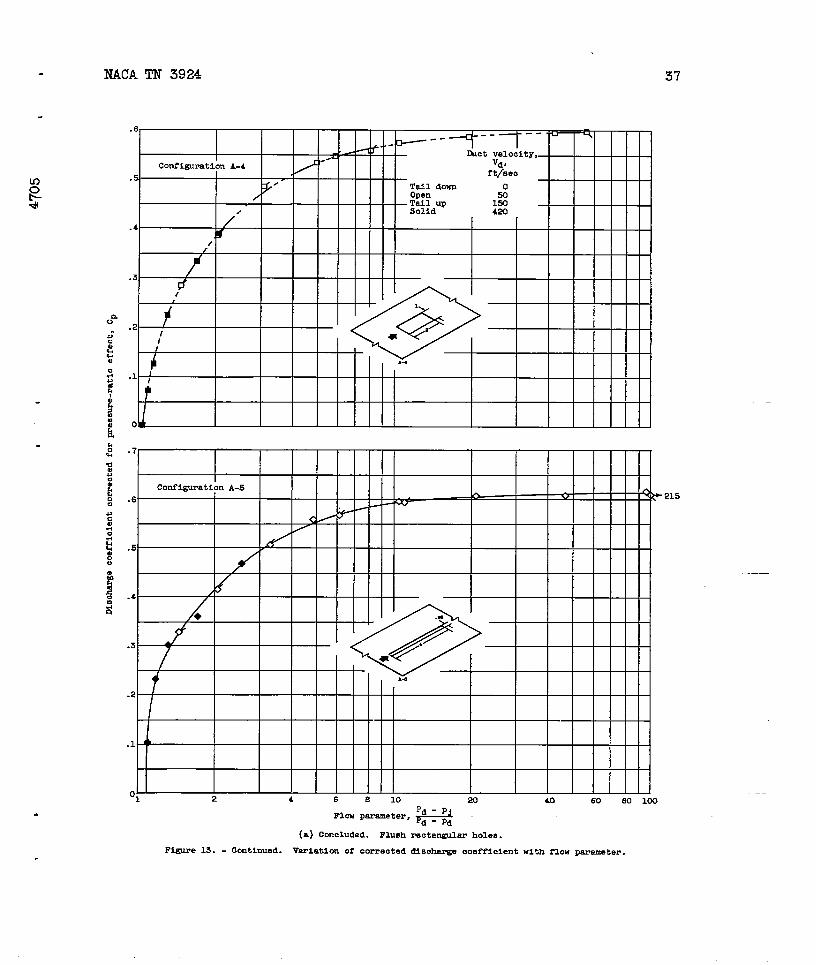
Pressure-ratiocorrection.- Thesecondstepisthecorrectionofdischargecoefficientsforpressure-ratioeffect.To obtaina pressure-ratiocorrectionfactor,thezero-duct-velocitydata(fig.3) for25configurationswererecalculatedas theratioofthedischargecoeffi-cientat a givenpressureratioto thedischargecoefficientat a pres-sureratioof 1.00(C/Cp).Thedatawerethenplottedagainsta generalformof thepressure-ratioterm(pd+ ~ sin8)/pj(fig-5)- For~ atr-entryconfigurationhavingitsfacenormaltothe-directionof ductflow(suchas a scoopor steplouver),19 equals90°,andthegeneralformofthepressure-ratiotermreducesto (pal+qd)/p.Jor pd/pj.Fora flushholeina parallel-walledduct,8 equalsO andthetermreducestoPd/P.~“ Forflushholesin inclinedductwalls,8 equalstheangleofinc&ationof thewall,and ~ equalsthedynamicpressureoftheductstreamat a planethroughthecenterofthehole. Thepressure-ratiocorrectioncurveofreference1 is includedin figure5. Althoughthedataforthevariousconfigurationsshowconsiderablescatterfromthecurveof reference1,thiscurve,whichdoesrepresenta meanvalue,wasusedforcorrectingdischargecoefficientsforallconfigurations.Discharge-coefficientdatawerethencorrectedforpressure-=tioeffectby dividingthedischargecoefficientC by a correctionfactorc/cpdeterminedfromfigure5. (Theparticulardataof fig.4, correctedforpressure-ratioeffect,arepresentedin figs.13(a)and(d),respectively.)
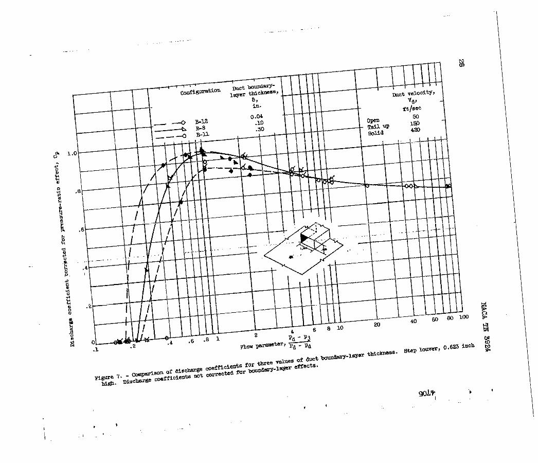
Boundary-layercorrection.- Thedatapresentedinfigures6 and7weretakenspecificallyforevaluatingboundary-~ereffectsonthedischargecoefficientsof steplouversandscoops.Reference1 indicatesthatboundarylayerhasa negligibleeffectondischargecoefficientsofflushholes.In figures6 and7 bothlouverheighth andboundsJT-layerthickness5 oftheductstreamwerevariedindependently.These

8
figuresshowthata variationthicknessmayaffectnotonly
NACATN 3924 .
in either.louverheightorboundary-layer ethedischargecoefficientbutalsothe
valueoftheflowparameterat zeroair@owthroughthelouver.
In an attempt to correct thelouverdataforboundary-layereffects,thedischargecoefficientsof figures6 and7 wererecalculatedonthebasisof effectivefaceareaof louver‘A~ asdeterminedby
~=(Af -b~*). Theboundary-layerdi~pkcementthickness .
/
8 25*= 1 (PJVJ- Pb2vbZ)W a
~svs o
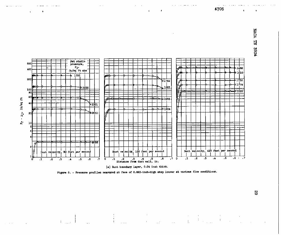
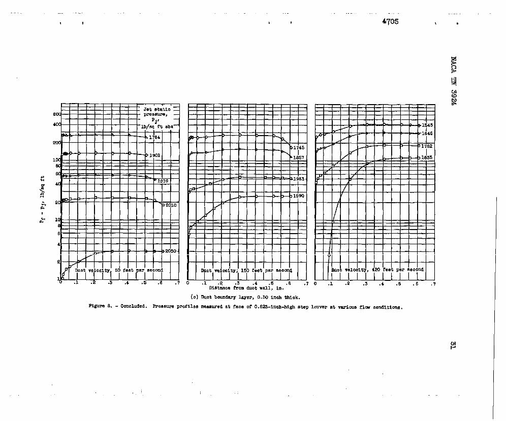
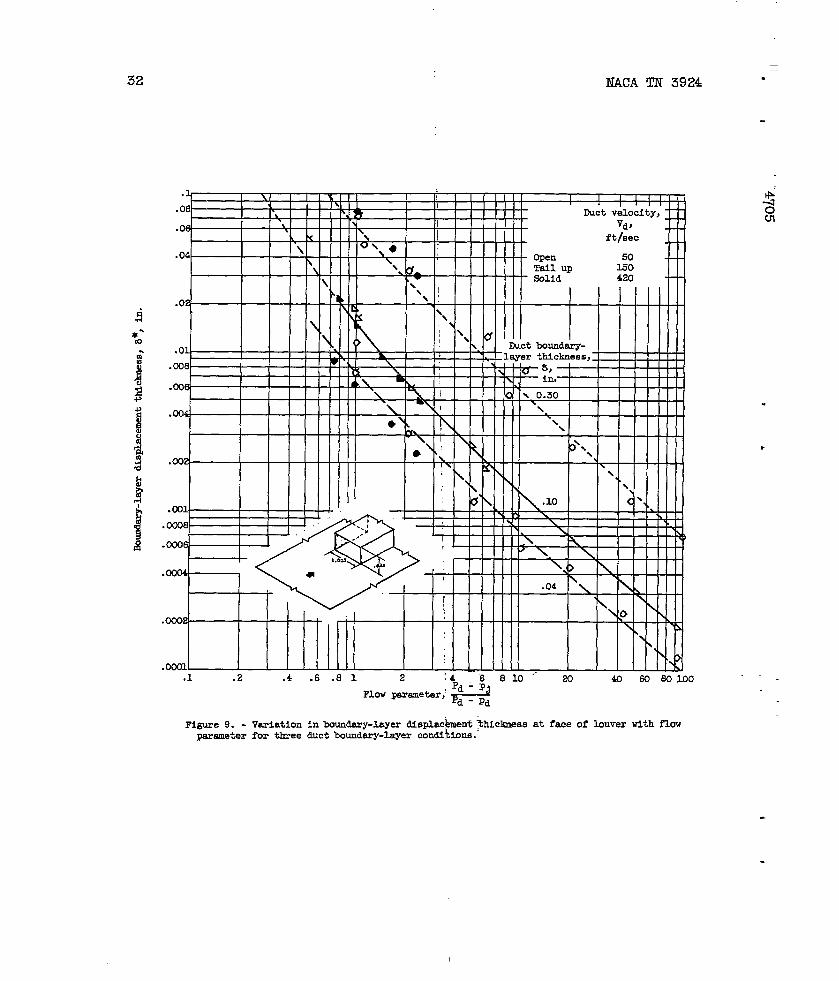
wasdeterminedfrompressureprofiles($’ig.8)measuredatthefaceofthe0.623-inch-highlouverat [email protected] showsthattheboundary-layerthickmessat thpfaceofa louvervariesnotonlywiththeinitialboundarylayerofthe$uctstreambutalsowiththeflowthroughtheopening.Figure9 showsth+v~iationin 5* withtheflowparameterforthethreeductboundary-tiy~conditionstivestigateda uPressureprofilesshowninfigure8(b)@~ounda@-layer displacement-thicknessvaluesshowninfigure9 for@[email protected]
—
0.10inchapplytoallconfigurationsofthisiuvestigatlonexceptB-11, ‘_B-12,andE-2toE-5. --- .=1 .—
Thedataof figures6 and7, corre@edforpressure-ratioeffectsandboundary-layerdisplacementthiclme$s,arereplottedinfigures10and1.1.,respectively.Thecorrecteddi@umge coefficient~,~* ataflow-parametervalueof 1.0isapproxi@tel.y0.95foralllouverheightsandboundary-layerconditionsinvestigated.At flow-parametervaluesgreatertha,uapproximately4.0,a decre~se-in10UV= heU& increases thedischargecoefficientslightly(fig.10). —
Fldw-parametervaluesat zeroairflowthroughtheopeningareofinterestbecausetheyindicatethel.ow&limitoftheflowrangeforagivenconfiguration.Variationinthis~valueoftheflowparameterforthevariouslouverandscoopconfigurat~onginvestigatedis showninfig-ure12asa functionof louveror scoop~height.AlthoughthedataShOWconsiderablescatterfromthefairedc@ve,a definitetrendis indicated.Theoretically,foranopeninghavingzeroheight(suchasa flushhole)thelowerlimitoftheflowrangewould:beata flowparameterof 1.0;conversely,iftherewereno walleffec$(alouveror scoopdetachedfromthewallandfunctioningasa Pito~tube)thelimitingvalueoftheflowparameterfora louveror scoopwouldbe zero. —
,...CorrelatedData ‘- .
Thedischame-coefficientdatafor:thevariousconfigurationswerecorrectedforpressure-ratiothiclmess,whereapplicable,
effects~ forboundary-layerdisplacementandareplbttedasa functionoftheflow

. NACAm 3924 9
4parameterin figure13. Includ~inthesefiguresaredischargecoeffi.cientsat zeroductvelocitydeterminedby extrapolationoftheapplicablefairedcurvesinfigure3 to a pressureratioof 1.00.Thesedataareplotted(fig.13)atvaluesoftheflowparameterobtainedfromtheapproximaterelation
Pd - Pj ()#2Pd-pd ~
DISCUSSION
RectangularSlots
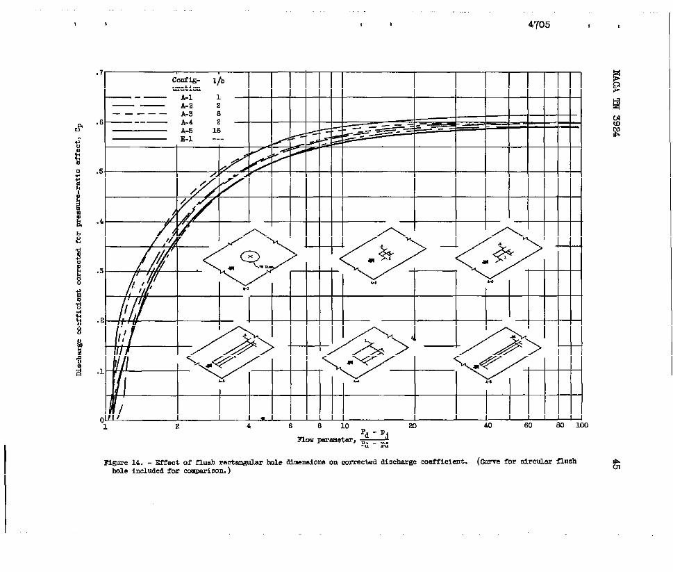
Effectof slotsize.- Fairedcurvesofthedischargecoefficientsforfiverectangularslots(configurationsA-1toA-5)arecomparedwiththatofa 0.750-inch-diameterflushcircularhole(configurationE-l)infigure14. In general,rectangularslotswiththeirma~ordimension. parallelto thetiectionof flowhavedischargecoefficientsslightlygreaterthanthoseforcircularor squareholes.As withcircularholes
3 (ref.1),holetidthhaslittleeffecton dischargecoefficientsforg widthsgreaterthan0.5inch(compareconfigurationA-2withA-4).
Effectof lengbh-to-widthratio.- Figure14 showsthatan increaseinthelength-to-widthratioofa rectangularslotincreasesthedischargecoefficientslightlythroughouttherangeoftheflowparameter.
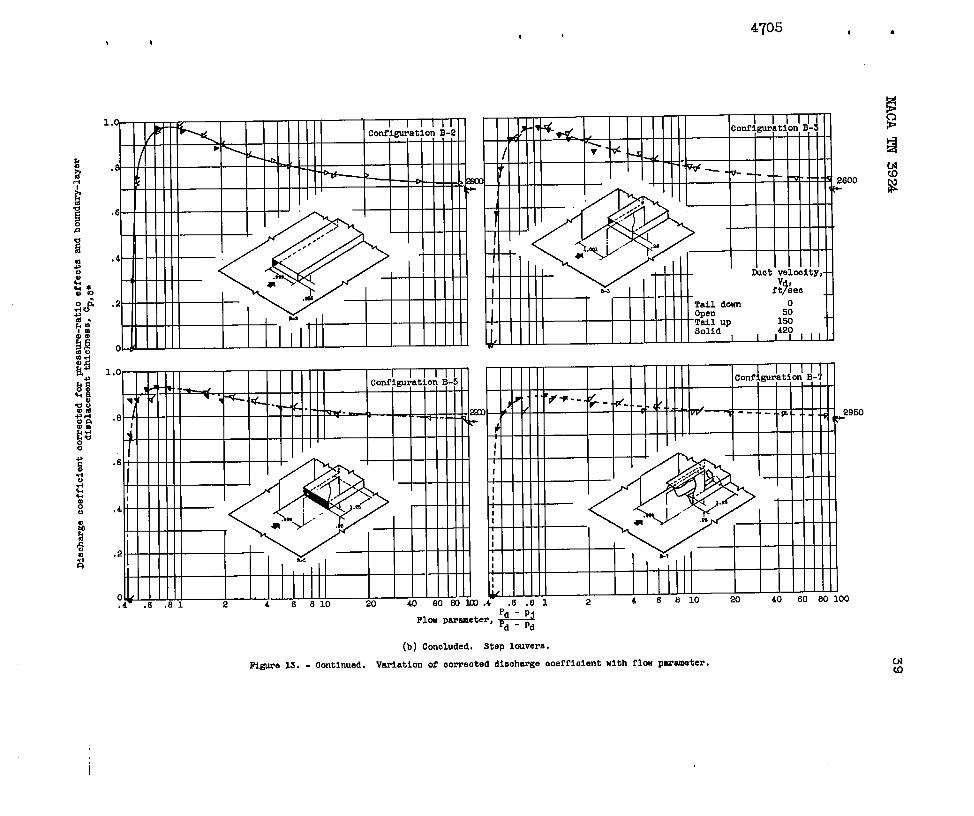
StepLouvers
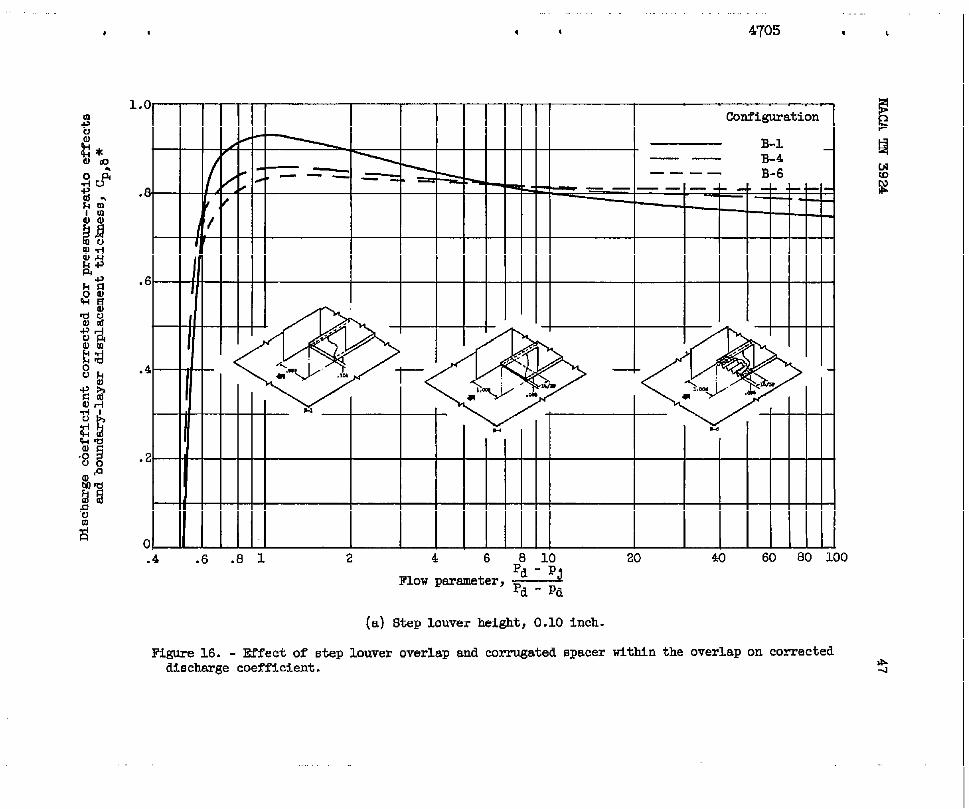
DischargecoefficientsCp,b* forstepl-ouv-s(figs.15to 17)aremaximumata flowparameterof 1.0anddecreasegraduallyat valuesgreaterandshsrplyat valueslessthan1.0. Theminimumvalueoftheflowparameterfora givenconfigurationwasshownin figure12tobe afunctionof louverheighth.
Effectof louverheight.- Fairedcurvesrepresentingdataforsteplouverheightsrangingfrom0.104to 0.623incharecomparedinfigure15.An increasein louverheightmayeitherdecreaseor increasethecorrect~dischargecoefficient,dependingonwhetherthevalueoftheflowparam-eterisgreateror less,respectively,thanapproxi=tely4.0.
Effectof louveroverlapandspacer.- Louverwalloverlaportheuseofa corrugatedspacerwithinthisoverlapis showninfigureM tohaveonlya smalleffectonthecorrecttidischargecoefficientforlouversapproxi~tely0.10and0.25inchhigh.
10 KAC.ATN 3924
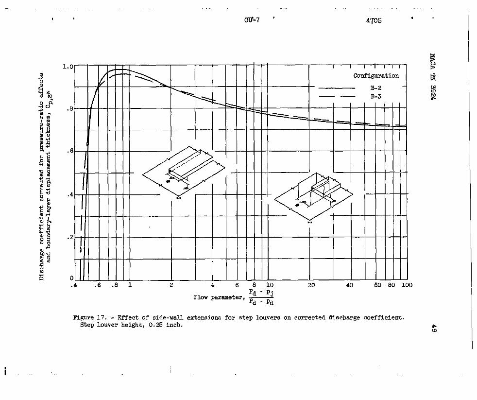
Effectof louverwidth.- Steplouv@sareoftendesignedasa con-tinuousopeningaround&e circumference~ofa combustorliner.Inordertodeterminethemagnitudeoftheside-wqlleffectsofthel-inch-wideexperimentalsteplouver,datawereobtainedforlouversbothwithandwithoutside-wallextensions.Extending~thesidewallsupstreamoftheplaneofthelouveropeningwasintended~toprevent’the3ateralflowofairacrosstheplaneofthesidewallsattheopening.ComparisonofdataforconfigurationsB-2andB-3(fig;17)indicatesthatforlouversupto 0.25inchhighside-walleffectsarenegligible.Thedata,there-fore,shouldbe.appl.icableto continuous“steplouvers.
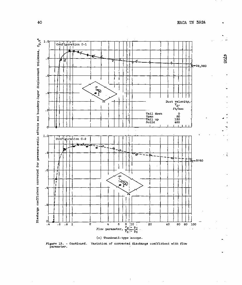
Thunibnail-Typ eScoops
Correcteddischargecoefficientsfoqthumbnail-typescoops(fig.M)aresomeWhatlowerthanthoseforsteplouversat lowvaluesoftheflowparameters.Aswithsteplouvers,thee~fectof scoopheightonthecorrecteddischargecoefficientis small.
z
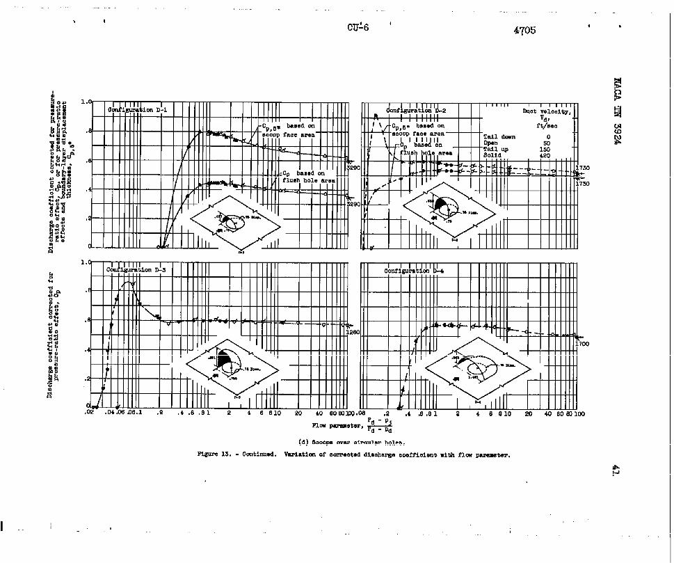
ScoopsoverCircu@rEoles &
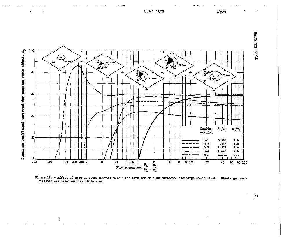
Fourdifferentscoop-over-holeconfigurationswereinvestigated.Forthreeoftheconfigurationsthedowndtr~mhalfofthescoopcoincideswiththeperimeterofthehole,thescoo~sdifferinginfacearearelativeto holearea;forthefourthconfigurationthebaseradiusistwicethatofthehole. Theholediameterwas0.750inchforthefourconfigurations.Althoughdischargecoefficientsareusual~basedonthesmallestflowareaoftheconfiguration,forpurposesof comparisonthecalculationsforconfigurationsD-1andD-2are bas~~onholearea(alargerarea)infigureM andon scoopfhcearea(thes~llestarea)in figure20.
Effectof scoopfacearea.- CorrecteddischmgecoefficientsforscoopsOV= circularholesarecomparedtith_thoseofa flushcircukhole(configurationE-l)infigure19. @se dataarecorrectedforpressure-ratioeffectbutnotforboundsmy-~erdisplacementthickness,sincethedischargecoefficientisbased’onltheholearearatherthanonthefaceareaofthescoop.Thesedata,therefore,arecomparablewiththoseofa flushcircularho&.
Figure19 showsthat increasingscoc@faceareaby increasingscmpheight(configurationsD-1,D-2,andD-3)notonlyincreasesthecorrecteddischargecoefficientthroughouttheflowr~e butextendstheflowrangeto lowervaluesoftheflowparameter.l)his..comparisonindicatesthemagnitudeoftheeffectof scoopfaceareaondischargecoefficientsbasedonflushholearea. Theaddition~f&ri0.891-inch-highsco~”toaflushholeextendstheflowrsmgefroma’flowparameterof1.0(config-urationE-1)to valueslessthan0.05(configurationD-3)becauseofr&m
—.
—--
. .NACATN 3924 —
● pressure(fig.19). At flow-parametervaluesfaceareaofapproximately1.4timestheholeisrequiredtoattaina dischsrgecoefficienthole(configurationE-l).
11
greaterthan20a scooparea(cotiigurationD-3)equaltothatofa flush
Effectofsizeof scoopbase.- Theeffectof increasingthesizeofthebaseof a scoopfromonethatcoincideswiththeperimeterof theholeto onehavinga radiustwicethatofpareconfigurationD-3withD-4),is
,3F throughouttheflowrange.Although+ matelyequalfaceareas,thereduced
junctionwithboundary-layereffectslowvaluesof theflowparameter.
thehole,alsoshowninfigure19 (com-to decreasethedischargecoefficientthesetwoconfigurationshadapproxi-heighto? configurationD-4incon-resultedina reducedflowrangeat
Comparisonwiththumbnail-typescoop.- Becauseofgeometricsimil-arities,thedischargecoefficientsofa thumbnail-typescooparecomparedwithth;seof scoop-aver-holeconfigurationsin figure20. Sincethedis-chargecoefficientsCp,~* in figure20arebasedon scoopfacearea,
+theyarecorrectedfor.bothboundary-layerdisplacementthicknessand
2 pressure-ratioeffect.yg Thecomparisonshowsthatthethuuibnail-typescoophasthehigher
dischargecoefficientthroughoutitsflowrsnge.A studyofthedataindicatesthatthedifferencein dischargecoefficientsforthethreeconfigurationsshownisa functionoftheflushholearea(inthepheof thewall)relativetothescoopfacearea ~~. Theeffectof scoopheightontheflowrangeat lowvaluesoftheflowparameterisagainapparent.
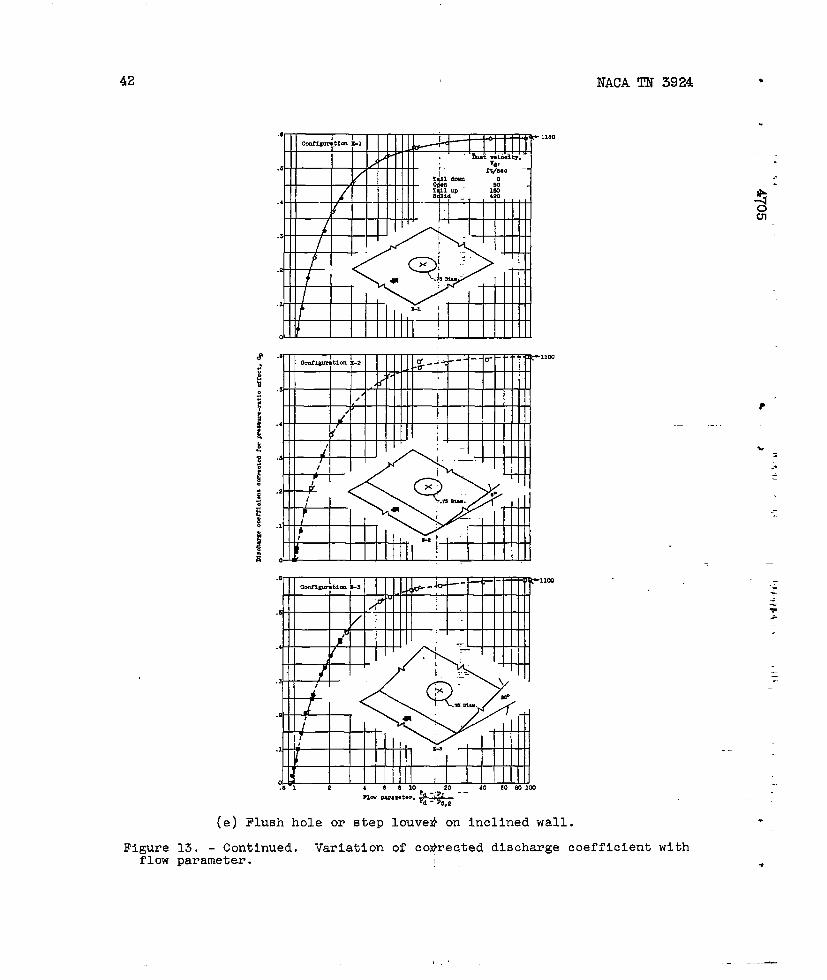
Holesad huverson Inc13medSurfaces
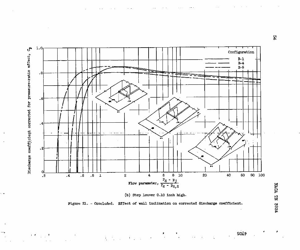
Inmanycombustordesignsthewallsofthelinerandtheoutershellarenotparallel.Theeffectof inclinedwallsonthedischargecoeffi-cientofa flushcircularholeanda steplouveris showninfigure21.
Flushcircularhole.- Correcteddischargecoefficientsfora 0.750-inch-diameterflushholemountedoninclinesof0°,8°,and20°arecomparedinfigure21(a).Dischargecoefficientsarepracticallyunaf-fectedlywallinclinationsupto 2Q0exceptfora smallrameffectatlowflowsthattendsto decreasethevalueoftheflowparameterforthe20°angle.
steplouvers.- Similarly,thedischargecoefficientsof a 0.105-. inch-highsteplouv~ (tithno overlap)muntedoninclinesof 0°,8°,
and20°arecoqaredin figure21(b).Sincethepressureprofilesobtained(fig.8)arenotapplicableto flowina convergentduct,the
12 NACAm 3924 *
dischargecoefficientsinfigure21(b)hrenotcorrectedforboundary. b
layerdisplacementthickness.Also,theeffectsoftheside-wallextensionsforlouversmountedonan in~linewerenotinvestigated.Thedifferencesindischargecoefficientsh@n.forthethreeconfigurationsmaybe partiallyduetovariationsinboundary-layerconditions.However,an increaseininclinationangletendstoincreasetheflowrangeat lowvaluesoftheflowparameter. .—
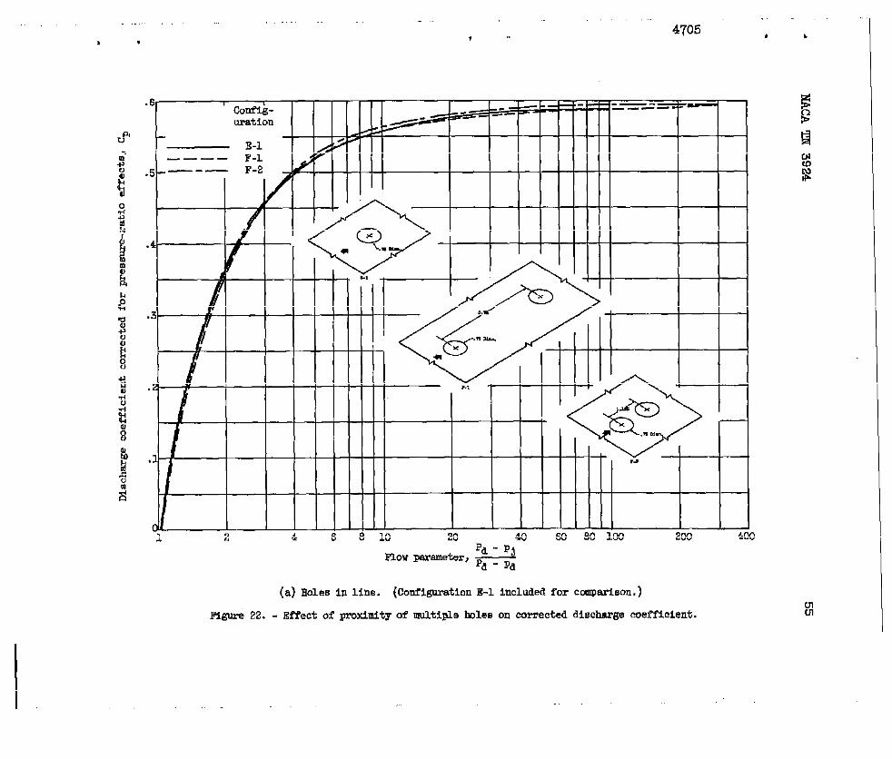
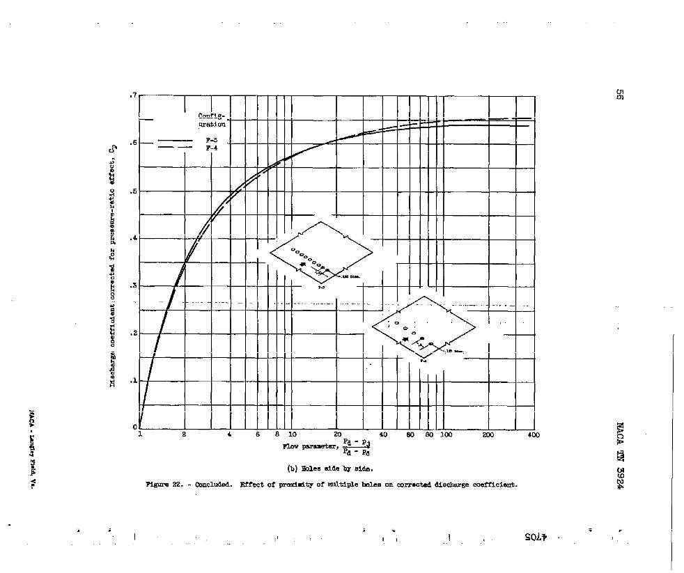
MultipleFlu8hHoles *4-%Theeffectofproximityofmultiplef~ushholesondischargecoeffi-
cientforbothin-lineandside-by-side,arrangementsispresentedinfig-ure22. Thedatapresentedindicatetheover-alldischarge coefficientfora givenmultiple-holeconfigurationWther thanforindividualholesof thatconfiguration.
. .
Holesinline.- Fairedcurvesrepr~sentingcorrecteddischargeco-efficientsfortwo0.750-inch-diameterf}ushholesspaced3.750and1.125 #3.nchesapart,center-to-center,ina 10
?itudinaldirectionarecompared
withthatofa singleholeinfigure22().__Theresultsindicatethatareductionin longitudinalspacingof cir&darholesfrom5 to 1.5diameters b
hasno effectontheirover-alldischmgecoefficient.In fact,thedataagreewellwiththoseforthesingleholethroughouttheflowrange.
=.Holessideby side.- A reductioniqthetransversespacingof 0.125-
inch-diameterholesfrom4 to 2 diameter+(center-to-center)is showninfigure22(b)tohaveno significanteffeqto“nthecorrecteddischargeco-efficientexceptathigh(above100)valdesoftheflowpsmuneter.
SignificanceofResults
Thedatapresentedshowthevariationindisctigecoefficientwitha flowparameterforvariousconfigurate.os of linerwallopenings.An
l!importantdifferenceinflowCharacteristiciSindicatedbetweentheflushholeandthescoopor steplouver..Withtheflushhole,theflowceasesastheflowparameterdecreasestoa valueof 1.0(i.e.,asthestatic-pressuredifferenceacrosstheope~ngapproacheszero);but,withthescoopandthesteplouver,flowconti~ues(becauseoframpressure)to somelowervalueoftheflowparameter~(dependQgontheheightofthescoop).Combustordesignshavinglowover-alltotal-pressurelossanda highairvelocityinthepassageou~sid,ethelinertendtohavealowor evena negativestatic-pressuredi~ferenceacrosstheupstreamlinerwal.1openings(ref.2). Thehighd$schargecoefficientof scoopsor louversat flow~arameterslessthan1.,0ties themessentialfor .
adequateairadmissionintheupstreamregionof suchliners..
.
.
●
✎ NACATN3924 13
*ApplicationofData
Theresultsofreferences3 and4 indicatethatdischargecoefficientsforholeshavingexternalflowonlyshouldbe applicableto ccmibinedin-ternalandexternalflow,ifthejetvelocityisgreaterthm thetiternalparallelflowvelocityandthecorrectjetoutletstaticpressureisused.Dischargecoefficientsforvariouslinerwallopeningsmsybe detezmdnedfrcmthecorrecteddischargecoefficientsinfigures14to 22 inthisreportorfrcxnapplicablefiguresinreference1 by thefold.owingmethod:
(1) At a givenvalueoftheflowpsrameter(pd- p~)/(pd- Fd)a cor-recteddischargecoefficientCp (or c-p,6*)cm be red frmna curve(figs.14to 22]selectedonthebasisofgecmetricsimil.szity(bothasto shapeandsize)to thegivenlinerwallopening.
(2)!lheccmrecteddischargecoefficient~, 6*f~ stePl~ers ~scoops(figs.15to 18 and20)mustfirstbe reducedto Cp by
.where5*,the boundary-l- tisp~~t t~c~ess~ ~Y ~ est~~dfranf@e 9 forthelocalflowconditim.Thelawerl-t oftheflowrangeforsteplouvers~d scoopsmsybe estimatedfrcmthecurveoffigure12.
(3)A pressure-ratiocorrectionfactorcj~figure5 atthegivenvalueofthepressureratio
(4)Theproductof (C/~)~ thenyieldsthecient C.
SUMMARYal?RESUL’IS
cambe obtainedfrcuu(pd+ ~ sin@/pj●
desireddischargecoeffi-
Thefollow5ngresultswereobtainedfrananevaluationoftheeffectsofvariousgecmetricandflowfactorson dischargecoefficientsforflushrectangularholes~ steplouvers~ ~d scoops:
1.Foreachconfigurationthedischargecoefficients,correctedforpressure-ratioandboundary-layereffects,Whereapplicable,werecorre-latedtitha dimensionlessflm p~ ter.
2.Theeffectsof sizeor shapeof flushrectangularholesondis-. chargecoefficientweresmallccmparedwiththeeffectsof ductstreamvelcwityandstatic-pressmratioacrossthehole.

14 NACATN3924 ●.
3.Theadditionofa SCOOPto a flushholeincreasedthedischarge bcoefficientandextendedtheflowrange&tIbwvaluesoftheflowparem-eterbutdecreasedthedischargecoeffic~entathighvaluesforscoopfaceareaslessthsn1.4timestheholearea.
4.Steplouvers~d scoopshadgreaerdischargecoefficientsaad1widerflowrangesatluwvaluesofthef owparameterthm theflushholes.
However,thedischargecoefficientinth~sregionwasaffectedby boundary-leyerconditionsoftheductstream,whereastheaxtentoftheflowrangeappearedtobe a functionofscoupheight.‘Thehighdischargecoefficients ~forlouverssmdscoupsatlowvaluesoftheflowparemetermakethemessentialfw adequateairadmissionintheupstresmregionofccmbust~ 8linershavinga lowstatic-pressurediff~renceacrosstheiropenings.
5.Forflushholesandsteplounrs~mountedinwallsofa convergentductwall,inclinatimsofupto 20°ha$littleeffectondischargecmffi-Cient.
6.Theproximityofthemultipleflushholesintherangefrom5 to1.5dismeters(center-to-center}h a lo&itudinaldirectionor4 to 2
z
diametersina trsmsversedirectionhaddo [email protected] Mschargecoefficient. *
LewisFlight=opulsicmLaboratoryNationalAdvisoryCommitteefaAermautics
Cleveland,Ohio,Deceniber6,1957
REFEREmm
1.Dittrich,RalphT.,ad Graves,CharlesC.: DischargeCoefficientsforCcmhstor-LinerAti-EntryHoles.I - CircularHoleswithPsmllelFlow.NAC!ATN3663,1956.
2.Grobman,J.S.,Dittrich,R. T,andG~am?s,C. C.: PressureDropandAirFlowDistributicmh GasTurbineCcdmstars.Tram.ASME,vol.79,110. 7,OCt. 1957,pp.1601-1607.:
3.Cdlaghaa,EdnrundE.,md Bowden,D+ T.: InvestigationafFIw CO-efficientofCircular,E@are,ad E,.lli.pticalOrificesatHigh-PressureRatios.NACATN 1947,1949,.
4.Dewey,PaulE.: A PreMuinaryInvesti’gationofAerodynamicCharacter-isticsofSmallInclinedAirOutlets’atTraIsonicMachNunibers.NACAm 3442,1955. (SupersedesNAC~RM L53C20.) .
.
.
TABLE1.- DETAT
OFAIR-ENTRYCONFIG~TIONSINVESTIGATEDAlldimensionsinInches.)
(a)FlushrectangularholesA-1toA-5
A-1
A-3
.
16-.
NACATN 3924 -
L
TASLE1.- CONTINUSD.DETAILSOFAIS-EliTRYCONFW’RATLONSINVESTIGATED(Alldimensionsih inches.i“(b)Steplcuvem d-l tdB-6 —
30Cn
B-1EL4
—8
.

. NACATN 3924
.
.
TABLE1.- coNTrNtlED.DSTAIL9OFAIS-6?FTRYCONFICWFiATIONSS,N’VESTIGATSD(Alldimensionsin inches.)(c)SteplcuversB-7toB-12
—w-lo
B-n

18 NACATN 3924
TABLE 1. - CONTINUED. DWJ?AIL9OF AIR-ENTRYCONFIGURATIONSINVESTIGATED(Alldimensionsin Inches.)
(d) Thumbnail-typelouversC-1 andC-2 at+dscoopsover clrnularholesD-1 to D-4
D:2
.
k
gi
Cn
.
.
—

19
TASL8I. - Co?wm. DSTAIL9W AIS.SXTRYCONFIGURATIONSINVSSTIGATSD(Alldlmene.iomin inches.)
(e)Holeor louverin inclinedwallI&l to E-5-.
@mlw
.
20 NACATN3924
TABLE1. -“CONCLUDED. DETAILSOF AIR-*Y c0mI13mATIoNsINVESTIGATED(Alldlrnenslons1+ Inclae.e.)
(f)Multiplecircularholes”~-1to F-4 —
.
.
.
.

—.
* [ 4705 , ,r
/“-\k:?ic tap.
4-Inah-wJlwe duutJ’-Cca-tki.atimsfl”h”.w—-.hot t+tal-presmm pmh
Q >.
% “-%‘:~~
. .mob“AOt&tiq$riiOr&teT
,.,“---.\ :,,’.:
.>>.,.:.:>,: ‘“:. .. .-% , .:.“.,..:$;:$} . :::,;.. .
Iklct“S’t.atio-wens!ueta?JB.... .,>,?. .,.. . -+..
1. 1
(a) Test plete flush with duct wall.
Figme 1. - D3tall,aof teat appatw for stu@yof disohergeooefflc lents.

Jw’Ym@EKi&,i
. .tii
,,..
..,: ,’,,; .
,.. d. ..=-+ -., ‘>+.J ,jij=’?,..
... .. .,:,, .,,,,:
., a
\\ L
,:.
{ .,., .”””
.\\w,.-...
(b) HMfiled far boumky-@er blsedoff.
Figuro 1. - Concluded. IM.911sof test a~tus fm studyof OXso?wrgecoafficlemtm.
u
* , r 4705” #
H+lllN/” ) I I I I
A A
.8
c
// -
1
K— = — — P
/ ~ - —/ -“
* ~
.2Y-
1 H--i-
1/./~.
0(.) Flwh ewe lmle (conflguratlonA-1).
/
/ .MllllllI I Ill\/--l Illlllriliil II
.2
/
o ! I.92 ,94 .96 ,98 “ ccl) 1.02 1.04 1.06 1.08 1.10 1.12 1.14 1.16 1.18
fkStiC-PM!3i3UIY rddo) pd/pj(b) SCWP over circulerhole (mnfig.u’aticmD-1).
Mgua’c 2. - Effect of static-prWm7re ratio on Mache.rgemeff’lcientat varlOuE duct velocities.
I is F 420
I I I I
A
.
.
.6
.6
.51.00 1.04 1.08 1.12 1.16 1.W 1.04 1.08 1.12 1.16 1.00 1.04 1.08 1.12 1.16
StatiO.presmn.e ratio, r+y% j
(a) Flush holes. (b) Step lcuvers and thumbnail8COOPB .
Pigllre 3. - Vamiatim in msoh.arge coefficients of 27 configurationsvelocity .
(.) Socmps over holes.
with pressure ratio at zero chmt
rid? , ‘ “

v CG4 , 4705 * v
u
(a) Blush wuare hole (oonfigmmtionA-1).
“~ p~~”’e”~~(b) Somp over oir.ularhole (ootilg!matimD-1).
mmm 4. - Va@latlOnin ~~chmge ooeffioientwith flow parawt.erat vnricw duet velooitleo.N(n

.-
I I I I I I I
CmfMMtion Ckmf@ration
0 A-1 0 c-lh A-2 0 C-20 A-3 n P-1
A-4 D P2: :: D-s
: D-4P B2 o E-1
v B-3 D E-2
1.10 A B-4 Q %3
v 2-5 a B-4A %6 o E-sP 2-7 F-1
z F-2
I.(2C2 / ‘
AJ
1.06
,..-...,-- .-- .-—. ,--..
()A
b
0Ud
i.w
7
02 s1.02 A
[1 0
1.00 1.M 1.02 1.12 1.16 l.m 1.24 l.za 1.32 1pd+~sine
Pres.wre-ratio tmrm,P$
Figure5. - RwmIre-ratio con-action factor fur discharge maffid~,
56
I . .*
t CUd bam..-.
4705 t
1.
.1 .2 .4 .6 ..9 1 8 10
b :_te,, @ 6
20 40 60 80 UN
d - Pa
Figure6. - ComDeri@nnof Uactige cnefficienimfor three heights of step louvem. LMCt boundary layer, 0.10 inch thick.Discharge coefficientsnot corrected fur bnundary-layer effects.
I. . .
Nal
I I) 1/
,0/
.6 i I
I\
I I I I 1 — ....S3. \ i i 17Ill
I t
HNIT \ I?l’i’ii!!!I
Hll+
, # 4705 “-; ,
o- .1 .2 .s .4 .5 .0 .7
t1 I ! 1 1 1 1 1 1 I 1 1 , !
Imot w lm:.@, 15ofeatv= aemn d
o .1 .’2 .3 ,4 .5 .6 .1Distanoefrm duetwall,in.
o ,1 .2 .3 .4 ,6 .6 .7
(a) rut bo.mdorg law, 0.04 1.* thiOk.
Pigurs.9.- RWmm profilesmmurecl at ram of O.623-inah-hi~steplouverat varlouMf1- ocmditi~.
N(9
1I 1

Lhot valmity, 50 feet per moond
1 I I I I I I I I I I Io .1 .2 .3 .4 .5 .6 .7
14111111111111DmtValooity,150 feetpm Ll,cond
o .1 .2 .3 .4 .5 ..2 .7Distanoe I’rcm dnot w.9.U,in.
.
0 .1 .2 .3 .4 .s .8 .7
(b)DIct bcurdary Iay*r, O.10 inch thi.k.
Ur.WO ~. . ccminuea. Premura LWOfileS measured at face of O .623-lmh-h@h step 10UWF at varicm fka comtims.
l,, .,,
I
,,. l,’
* mLTf;, .,. .118,8 :)! ,,
CNo
!2
.
!
111171111111111mm’ ‘C.dty;’Mb At ‘p& P.&h
o .1 .2 .s .4 .5 .6 .7Dinttioe from duet wall, in.
(o) ~at bundary lwer, O.XI inch thlok.
4705
, I , , , I , 1 1 , 1
I I I I I I I I I I I
I i I L I L I L I1345
h-i- 1-1 L I L I L I1146 I
, ,
0 .1 .2 .3 .4 .5 .6 ,7
~ a. - Concluded.Prmoum PI.OM1OBmummed at faoeof O.623-inch-hi@steplouverat mriaua fleaoonditioon.
.,
32 .
.
.
-. 40 60 eolooFlowparameter;~
%oCn
Figure9.- Vmiattoninboundary-layerdisplacPen~~hicknessat faceof louverulthflow
parameter forthreeductboundary-layercondilone.“
.

1.
is
\II

1
.-
— .-P. - n.
hwe ~. - COmparimm of d!acharge cmfficienta forthee valuesof duct boumdmy-lmer thidmem. S@ louver, O. 62Sinchhigh. Eiwharge cuefficientacorrected for Fessw’e-mtio effects ad bomdary-lwer displacecmnt thickusa. ;“
1’b
I ., 1.
b 1 sol!? I .
I ,1.

.
* CU-5badk 4705 !
1.0 1 1 1 1 I I
configuration Configuration
hQ B-1 o E-10D %2 o B-n
.8v B-3 o B-12A B-4 o c-lw B-5 oA B-6 n
\ v B-7 DA B-8 v
} b o B-9 a.6 \
n b L,4
QDuctvelocity,
Vs.)ft/sec
\●+
.2- Open 50 \Tailup 150Eblid 420 0
c-2D-1D-2D-3D-4
o .1 .2 .3 .4 .5 .6P~ - pj
‘ow ‘mmeter’ pd - pd
Figure12.- Variationof flow-paxemetervalueaat zeroflowthroughopeningwithEcooporlouverheight.
I

36
L?
NACATN 3924 .
Figure13.-
(a)Flushrectangtil=-holes.
Varlati.onof correcteddlsch~ge“coefficientwithflow
.-
parameter.
.
—
.--
.—
,.—
,
I —.
.
NACATN392A 37
##
v v
40 I I I J=llll~ I I #l I I Illk%# .4
8
.3
.2
.1
01 2 4 6 8 10 20 Lo 60 do 100
215
Flawp= ““~(a)Concluded.Flu8hreotewlarholes.
-e 13.- Cmtlnued. Variationorcorrecteddischargecoerf’lclentwithflowparameter.

38 NACATN3924 .
133
1.
27
,4,180
‘1”‘“-t”’ *(b)Steplouveps.
I,750
.
.
Figure13.- Continued.Vartationof corrqcted.dischargecoefficientwithflowparameter. :
—
9 I4705 8 4
a1..
600
1.
00
‘1~ p@J’meter)~(b)Conaluded,Step10UVCrE.
Figura13.- Continued.Variationof oorremteddioohargecmffIolentwithflewparameter. (.Nm
I
40 NACATN 3924
1.
28,380
.
1‘
5780
.
“w ‘=meter’ ~-”
(c)Thumbnail-type’scoops.
Figure13. - Continue~. Variationof correcteddischargecoefficientwith flowparameter.
—
$jUI
.
.
.
I
mm -Oter, ~
(d) doocw over airmlar holcm.
Ww’e 1s.- Cmtlnmd. ‘fariatim of o-tad dimhnrge ocmffloinn% wibhClm v*,
42 NAC!ATN 3924 ●
.,1s0
....
$jCn
,llW
1103
n- Pumtal-,“*-- .(e)Flushholeor steplouvedon tnclinedwall.
Figure13, - Continued.Variationof cotirecteddischargecoefficientwithflowparameter.
P
-..
—
—.
.
,.

NACATN3924
Ino5 1.
,260
.
1.0
..9,000 ,
.6
.4
.2
0.2 .4 .6 .a1 20 40 60 601WJ
‘f” ‘“”’~’” &g
(e)Oonaluded.Flushholeor steplouveron inclinedwall.
.
Figure13.- Continued.Variationof correcteddi8chargeooefficientuithflowparameter.
.

I
.6
,6
.4
.5
.2
M“”rt/mo
.1ml dmu o
J_c.’mml up
r solid1%420
0b
.1
.6
1 24 681OZO Wmmlm m m 1 04 Ll alo -xl 4e .mmux 5c0 ue
w,- 9mawta-,~
(f) Multlple circular holes.:1
Figure 13. - Concluded, Verlatlon of oorrected discharge coefficient with flm parametxzr.
I , < 1 4705 I t
Rlgore 14. - Effect of fluuh ractanaularimle dlmsn.sioneon correcteddiwhzwa cnofficient. (@rve for oircul.mflnehhole includedfor ccmparlmn.)
I&.rn

l——
4=--—
6
4
-. .,..
2 /
/
0 /.1 .2
1.0
Flowwr.ter, ~
Figure1.5.- EPfect of step louver k%ht on corrected dimharge coefficlmt.
I
1 ,
II 1
01
s.
#
E-—1 IL 1
I1 I I I I
I
.6
.4
.Z
0EE.4 .6
* , 4705 a
.8 1 2 4 6 -8 10 20 4060 80 100—
Flow parameter, ~
(a) 6tep louver height, 0.10inch.
Figure 16. - Effect of Btep louver overlap and corrugated spacer within the overlap on correcteddischarge coefficient.

—..- ..
1
f
.
.4 .6 .8 1 2 4 6
1 #
1 1 I t 1 I I
Conflguratlon
—— E-3—-— B-5
E-.
10 20
—“
—
40 60 80 103
L&.
P~ - PjFlawWameter, ~d- ~d
(b)Step lower height, 0.25 inch.
Figure 16. - Concluded. Effect of step louver overlap and corrugated 8pacer wlthln the overlap w
on corrected discharge coefficient. i
:, I
. . ● rSO,l.v
1 CU-7 ‘ 4705 ‘
1.0
.8
.6
.4
.2
0.4 .6 .8 1 2 4 6 8 10 20 40 60 80 100
pa - Pj
‘lOw ‘met=’ Pd - Pd
Figure 17. - Effect of side-well exkmiona for Blq louvers on corrected discharge coefficient.Step louver height, 0.25 Inch. IF.
m
I I

.
1.0
.8
.6
.4
. .
:,
. .2
0.
—
/7
.6 1 2 4 6 8 10 20 40 En 80 100g
Figure 18. - Effect of height of thumbnsil-type scoops on corrected discherge coefficient.
SO.L7!’1
r ‘%,’ ,“
I I
n
.
CU*7lack 4705 “
J4 1.0
..9
.6
.4
.2
0.01 .02 .04 ,06 .08 .1 .2 .4 .6 .81 _ 2 46 8 10 20 40 m 50100
Flow parawt.,;=
Figure 19. - Effectof Bizeof scoopnwunttioverflushcircularbole on mrrected clisc=ge coefficient.Mscharge coaf-flcientserebesedon flushW area.
WP
1

rnRi
1
Fi@re 20. - CmpariOOn of dischergecoefficientsfor =aOp-over-tiletiththmb~l-m Bcoop. DiecharsecOefficietibasedon sceapface area.
‘1 I
x w S0,L7 . ,I

“
.
NACATN 3924 53
.6Configuration
—--- — E-2—-— E-3
.5
A’
.4
t
.3
.2
KI
.1
i’ttibt-t m-i--H-o~.8 1 2
<2’‘1
Qx
K/.,5 MA..
- 11
4 6 8 10 20 40 w 80 100
Flow parameter,Pa - pJpd - Pa,2
(a)Flush circularhole tith 0.75-inchdhneter.
Figure 21. - Effectof well inclinationon correcteddischargecoefficient.
+--u2kal
.
.2 .4 .6 .8 1 2 4
!!!”,,~
6 8 10 20 40E41 W 100
% - Pj
?FI.OVpa==ter, Pd . ~d,~
s(b) kWp louver 0.10 inch high.
Q
Figure 21..- Concluded. Effect of wdl inclination on corrected discharge coefficient. CN
$
P , SOL+ ‘ ‘,.,
, , ,4705
1 2 4 6 8 10 20 4060 so 100 zoo 4(X
324‘ow ~metir’ Pfl- p~
(a)Holes In line. (Coufigoration E-1 includedfor ccawarieon.)
Figure22. - ~ect of proximityof multiplelmles on correcteddiechargecoefficient.
.7
.E
.5
.4
.3
.1
.1
c
=TrrrtT
/
m.G tm+mt---1----- - -- A. -------- ----- ..
I 1 1 1 1 1 1 I
I I I I I 1 I I
2 4 6 8 10 20 40 EJ2 m lm m 4
m.w Wmm=ter, ~
(b)Eole66i.5eby aide.
-22. - CmcMd. Effectof rn-=iti~ or ~ti~e -m on mrrmted M3cher.secoefficient.
, J
I 1’, :, .
II 1,
0
SOL?
mm
. ,


![hLllsoE lliE llllllllllllll, ElilliilE-Lindley process [1] modified by replacement. An algorithmic procedure will be given for evaluating the sequence of distributions of Wk recursively](https://static.fdocuments.us/doc/165x107/5f0aab047e708231d42cbfd4/hlllsoe-llie-llllllllllllll-elilliile-lindley-process-1-modified-by-replacement.jpg)


