Technical support: +49 (0)7223 / 9493-0egmont.com.pl/addi-data/instrukcje/Pa110_e.pdf · l by using...
29
Technical support: +49 (0)7223 / 9493-0 Technical description ADDINUM PA 110 64 digital input channels 5 th edition 03/2000
Transcript of Technical support: +49 (0)7223 / 9493-0egmont.com.pl/addi-data/instrukcje/Pa110_e.pdf · l by using...

Technical support:
+49 (0)7223 / 9493-0
Technical description
ADDINUM PA 110
64 digital input channels
5th edition 03/2000

Copyright
All rights reserved. This manual is intended for the manager and its personnel.No part of this publication may be reproduced or transmitted by any means.Offences can have penal consequences.
Guarantee and responsibility
Basically are effective our "general terms of delivery and payment". The manager receives them atthe latest with the invoice. Claims for guarantee and responsibility in case of injuries and materialdamages are excluded, if they are due to one or some of the following causes:
- if the board has not been used for the intended purpose- improper installation, operation and maintenance of the board- if the board has been operated with defective safety devices or with not appropriate or non-functioning safety equipment- nonobservance of the instructions concerning: transport, storage, inserting the board, use, limit values, maintenance, device drivers- altering the board at the user's own initiative- altering the source files at the user's own initiative- not checking properly the parts which are subject to wear- disasters caused by the intrusion of foreign bodies and by influence beyond the user's control.
Licence for ADDI-DATA software products
Read carefully this licence before using the standard software. The right for using this software isgiven to the customer, if he/she agrees to the conditions of this licence.- this software can only be used for configuring ADDI-DATA boards.- copying the software is forbidden (except for archiving/ saving data and for replacing defective data carriers).- deassembling, decompiling, decoding and reverse engineering of the software are forbidden.- this licence and the software can be transferred to a third party, so far as this party has purchased a board, declares to agree to all the clauses of this licence contract and the preceding owner has not kept copies of the software.
Trademarks
Borland C and Turbo Pascal are registered trademarks of Borland International, INC.Burr-Brown is a registered trademark of Burr-Brown CorporationIntel is a registered trademark of Intel CorporationAT, IBM, ISA and XT are registered trademarks of International Business Machines CorporationMicrosoft, MS-DOS, Visual Basic and Windows are registered trademarks ofMicrosoft Corporation
The original version of this manual is in German. You can obtain it on request.

i
WARNINGIn case of improper handling and if the board is notused for the purpose it is intended for:
people may be the board, PC and the environmentinjured peripheral may be may be
damaged polluted
««« Protect yourself, other people and the environment«««
• Do read the safety leaflet!
If this leaflet is not with the manual, please contact us.
• Observe the instructions in the manual!
Make sure that you have not forgotten any step. We are not liable for damage resultingfrom a wrong use of the board.
• Symbols used
WARNING!It designates a possibly dangerous situation.If the instructions are ignored the board, PC and/or peripheraldevices may be damaged.
IMPORTANT!designates hints and other useful information.
• Do you have any question?
Our technical support is always glad to help you.


iii
Declaration of ConformityThis declaration is valid for the following product:
ADDINUM PA 11064 digital inputs, 24 V, optoisolated,
It is made by
ADDI-DATA GmbHMeß- und Steuerungstechnik
Dieselstraße 3D-77833 Ottersweier
in sole responsibility and is valid on the understanding that the product is competently installed, used andmaintained, according to the respective security regulations as well as to the manufacturer's instructions
regarding its intended use.
This declaration states that the product complies with following EC Directives:
l EWGRL 336/89 of 3.05.1989l EWGRL 31/92 of 28.04.1992l EWGRL 68/93 of 22.07.1993
This declaration is valid for all units manufactured according to themanufacturing references listed in the form TD110.020.
Following norms have been applied to test the productregarding electromagnetic compatibility:
l EN55011/03.91l EN55022/08.94l EN50082-2/03.95
We point out that
l the conformity and herewith the permission of use expire if the user alters the product without consulting with the manufacturer.
l non-skilled users are to have the operational area of the product and the requirements resulting from it checked prior to putting into operation.
l by using this product in appliances coming under the EC EMC Directive, the user is to make sure they are conform to its regulations prior to putting into operation.
l by using this product in machines / installations coming under the EU Machine Directive, the user is to make sure they are conform to its regulations prior to putting into operation.
A copy of the EMC tests is at your disposal on request.
15th October 1995 Legally valid signature of the manufacturer


Table of contents PA 110
I
1 INTENDED PURPOSE OF THE BOARD ..................................................... 1
1.1 Limits of use ....................................................................................................... 1
2 USER .................................................................................................... 2
2.1 Qualification ...................................................................................................... 2
2.2 Personal protection ........................................................................................... 2
3 HANDLING THE BOARD ......................................................................... 3
4 TECHNICAL DATA.................................................................................. 4
4.1 Electromagnetic compatibility (EMC) ................................................................ 4
4.2 Physical set-up of the board.............................................................................. 4
4.3 Limit values ........................................................................................................ 5
5 SETTINGS..............................................................................................6
5.1 Settings at delivery ............................................................................................ 65.1.1 Component scheme .................................................................................................. 65.1.2 Jumper location and settings at delivery .................................................................... 75.1.3 Base address setting through jumpers......................................................................... 7
6 INSTALLATION....................................................................................... 8
6.1 Inserting the board ............................................................................................ 96.1.1 Opening the PC .......................................................................................................... 96.1.2 Plugging the board into the slot ................................................................................ 106.1.3 Closing the PC........................................................................................................... 10
6.2 Software........................................................................................................... 116.2.1 Installation under DOS or Windows 3.11..................................................................... 116.2.2 Programming ............................................................................................................ 11
Example with the base address 0390H (set at delivery)............................................. 11Check whether a channel is set or not ...................................................................... 11
6.3 Error analysis per Internet ................................................................................ 11
7 CONNECTION TO THE PERIPHERAL .....................................................12
7.1 Connector pin assignment............................................................................... 12
7.2 Connection principle....................................................................................... 13
7.3 Screw terminal boards PX 901 and PX 9000.................................................... 13
8 FUNCTIONS........................................................................................14
8.1 Board description ............................................................................................ 14

PA 110 Table of contents
9 STANDARD SOFTWARE........................................................................15
9.1 Introduction ..................................................................................................... 15
9.2 Software functions ........................................................................................... 179.2.1 Address...................................................................................................................... 17
1) i_PA110_SetBoardAddress (...) ....................................................................................... 172) i_PA110_CloseBoardHandle ........................................................................................... 17
9.2.2 Digital input channels ................................................................................................ 181) i_PA110_Read1DigitalInput (...) ..................................................................................... 182) i_PA110_Read8DigitalInput (...) ..................................................................................... 193) i_PA110_Read16DigitalInput (...) ................................................................................... 204) i_PA110_Read32DigitalInput (...) ................................................................................... 21
Figures
Fig. 3-1: Wrong handling ........................................................................................................ 3Fig. 3-2: Correct handling ...................................................................................................... 3Fig. 5-1: Component scheme ............................................................................................... 6Fig. 5-2: Jumper location on the PA 110 ................................................................................ 7Fig. 6-1: Types of slots ............................................................................................................. 9Fig. 6-2: Opening the protective packing .............................................................................. 9Fig. 6-3: Inserting the board ................................................................................................. 10Fig. 6-4: Securing the board at the back cover ................................................................... 10Fig. 7-1: 37-pin SUB-D male connector (front connector)..................................................... 12Fig. 7-2: 37-pin SUB-D male connector (cabled to the board)............................................. 12Fig. 7-3: Connection principle.............................................................................................. 13Fig. 7-4: Connection to the screw terminal boards PX 901 and PX 9000 ............................. 13
Tables
Table 9-1: Type Declaration for Dos and Windows 3.1X ....................................................... 15Table 9-2: Type Declaration for Windows 95/NT .................................................................... 16

Technical description Chapter 1 PA 110
1
1 INTENDED PURPOSE OF THE BOARD
The board PA 110 is the interface between an industrial process and a personalcomputer (PC).It is to be used in a free ISA slot. The PC is to comply with the EU directive89/336/EEC and the specifications for EMC protection.
Products complying with these specifications bear the mark.
Data exchange between the board PA 110 and the peripheral is to occur througha shielded cable. It has to be connected to the 37-pin SUB-D male connector ofthe board PA 110.
The board has 64 input channels for processing digital 24 V signals.
The use of the board PA 110 in combination with external screw terminalboards is to occur in a closed switch cabinet; the installation is to be effectedcompetently.
Check the shielding capacity of the PC housing and of the cable prior toputting the device into operation.
The connection with our standard cable ST010 complies with the specifications:- metallized plastic hoods- shielded cable- cable shield folded back and firmly screwed to the connector housing.
Uses beyond these specifications are not allowed. The manufacturer is not liablefor any damages which would result from the non-observance of this clause.The use of the board according to its intended purpose includes observing alladvises given in this manual and in the safety leaflet.
1.1 Limits of useThe use of the board in a PC could change the PC features regarding noiseemission and immunity. Increased noise emission or decreased noise immunitycould result in the system not being conform anymore.
Our boards are not to be used for securing emergency stop functions.
The emergency stop functions are to be secured separately.This securing must not be influenced by the board or the PC.
Make sure that the board remains in the protective blister packing until it is used.Do not remove or alter the identification numbers of the board.If you do, the guarantee expires.

PA 110 Technical description Chapter 2
2
2 USER
2.1 Qualification
Only persons trained in electronics are entitled to perform the following works:• installation,• use,• maintenance.
2.2 Personal protection
Consider the country-specific regulations about• the prevention of accidents• electrical and mechanical installations• radio interference suppression.

Technical description Chapter 3 PA 110
3
3 HANDLING THE BOARD
Fig. 3-1: Wrong handling
Fig. 3-2: Correct handling

PA 110 Technical description Chapter 4
4
4 TECHNICAL DATA
4.1 Electromagnetic compatibility (EMC)
The board has been subjected to EMC tests in an accredited laboratory inaccordance with the norms EN50082-2, EN55011, EN55022The board complies as follows with the limit values set by the normEN50082-2:
True value Set valueESD ................................................................ 4 kV 4 kVFields .............................................................. 10 V/m 10 V/mBurst ............................................................... 4 kV 2 kVConducted radio interferences ......................... 10 V 10 VNoise emission................................................ B class
WARNING!The EMC tests have been carried out in a specific applianceconfiguration. We guarantee these limit values only in thisconfiguration1) .
Consider the following aspects:- your test program must be able to detect operation errors.- your system must be set up so that you can find out what caused errors.
4.2 Physical set-up of the board
The board is assembled on a 2-layer printed circuit card.
Weight: 150 gWeight of the supplied cable: 50 gInstallation in: XT / AT slotConnection to the peripheral: 37-pin SUB-D male connector
Cables: standard cable ST010, ST011Screw terminal boards: PX 901-D,
PX 901-DGor PX 9000
See Fig 7-4: Connection to screw terminal boards
1) We transmit our appliance configuration on request.

Technical description Chapter 4 PA 110
5
4.3 Limit valuesOperating temperature: ................................... 0 to 60°CStorage temperature: ...................................... -25 to 70°CRelative humidity: .......................................... 30% to 95% non condensingMinimum PC requirements:ISA bus interfaceBus speed: ...................................................... 8 MHz
Energy requirements:Operating voltage: .......................................... 5 V ± 5%Current consumption (+ 5 V of the PC): ......... 136 mA ± 15 mA
24 V digital input channelsInput type: ...................................................... Common ground in accordance........................................................................ with IEC1131-2Number of input channels: .............................. 64Nominal voltage: ........................................... 24 VDCInput current at nominal voltage: .................... 15 mALogic input level: ........................................... UH
1) max.: 28 V UH min.: 16 V UL
2) max.: 12 V
UL min.: 0 VSignal delay: ................................................... 65 µs (at nominal voltage)Maximum input frequency: ............................ 5 kHz (at nominal voltage)
SafetyOptical isolation: ............................................ 500 V
1 UH: input voltage which corresponds to logic "1"2 UL: input voltage which corresponds to logic "0"

PA 110 Technical description Chapter 5
6
5 SETTINGS
5.1 Settings at delivery
5.1.1 Component scheme
Fig. 5-1: Component scheme

Technical description Chapter 5 PA 110
7
5.1.2 Jumper location and settings at deliveryFig. 5-2: Jumper location on the PA 110
The base address is 0390H
5.1.3 Base address setting through jumpers
The base address of the board is set through 8 jumpers marked 1 to 8.The board requires 8 I/O addresses.The jumpers correspond to the address bits as follows:
Jumper: J8 J7 J6 J5 J4 J3 J2 J1Address bit: A10 A9 A8 A7 A6 A5 A4 A3
The board is delivered with the following configuration: I/O address 0390H
IMPORTANT!A jumper which is set meant logical 0A jumper which is not set means logical 1
Jumper: J8 J7 J6 J5 J4 J3 J2 J1Logical state: 0 1 1 1 0 0 1 0

PA 110 Technical description Chapter 6
8
6 INSTALLATION
IMPORTANT!If you want to install simultaneously several ADDI-DATA boards,consider the following procedure.
• Install and configure the boards one after the other. You will thus avoid configuration errors.
1. Switch off the PC2. Install the first board3. Start the PC4. Install the software (once is enough)5. Configure the board
6. Switch off the PC7. Install the second board8. Start the PC9. Configure the boardetc
IMPORTANT!You have installed already one or more ADDI-DATA boards in yourPC, and you wish to install an additional board?
Proceed as if you wished to install one single board.
Technical description Chapter 6 PA 110
9
6.1 Inserting the board
IMPORTANT!Do observe the safety instructions.
6.1.1 Opening the PC• Switch off your PC and all the units connected to the PC.• Pull the PC mains plug from the socket.• Open your PC as described in the manual of the PC manufacturer.
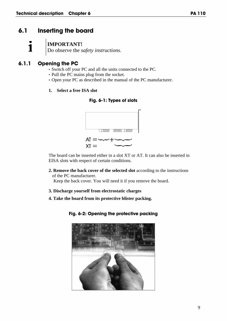
1. Select a free ISA slot
Fig. 6-1: Types of slots
The board can be inserted either in a slot XT or AT. It can also be inserted inEISA slots with respect of certain conditions.
2. Remove the back cover of the selected slot according to the instructions of the PC manufacturer. Keep the back cover. You will need it if you remove the board.
3. Discharge yourself from electrostatic charges
4. Take the board from its protective blister packing.
Fig. 6-2: Opening the protective packing

PA 110 Technical description Chapter 6
10
6.1.2 Plugging the board into the slot
• Discharge yourself from electrostatic charges
• Insert the board vertically into the chosen slot.
Fig. 6-3: Inserting the board
• Fasten the board to the rear of the PC housing with the screw which was fixed on the back cover.
Fig. 6-4: Securing the board at the back cover
• Tighten all loosen screws.
6.1.3 Closing the PC
• Close your PC as described in the manual of the PC manufacturer.

Technical description Chapter 6 PA 110
11
6.2 Software
6.2.1 Installation under DOS or Windows 3.11The board is delivered with one 3,5" diskette which contains the device driver.- Insert the diskette in a drive and change to this drive- Enter <INSTALL>- The installation program gives you further instructions.
IMPORTANT!Please read the files README.TXT (update of the device driver).
6.2.2 Programming
For the data exchange between the CPU and the board 8 addresses are assigned,which are differentiated through the 3 lowest address bits.The higher address bits A3-A10 are compared with the jumper adjustment.The address bits A11-A15 are pre-decoded with „0“.The board needs no software initialisation. It can be directly related to itsprogrammed address, for example with the Basic command INP.
Example with the base address 0390H (set at delivery)
The 64 digital input channels are read with these commands:A = INP (&H0390) E = INP (&H0394)B = INP (&H0391) F = INP (&H0395)C = INP (&H0392) G = INP (&H0396)D = INP (&H0393) H = INP (&H0397)The input channel 1 corresponds to bit 0 of INP (&H0390)The input channel 32 corresponds to bit 7 of INP (&H0393)The input channel 64 corresponds to bit 7 of INP (&H0397)
Check whether a channel is set or not
Example for channel 4:A = INP (&H0390)IF ( A AND &H08) = &H08 THEN PRINT “INPUT 4 = 1 „ELSE
PRINT „INPUT 4 = 0“Example for channel 10 and channel 16:B = INP (&H0391)IF ( B AND &H82) = &H82 THEN PRINT “INPUT 10 and 16 = 1„ELSE
PRINT „INPUT 10 and 16 = 0“
6.3 Error analysis per Internet
Do not hesitate to e-mail us your questions:- e-mail: [email protected] per Internet : http://www.addi-data.de. or
http://www.addi-data.com
PA 110 Technical description Chapter 7
12
7 CONNECTION TO THE PERIPHERAL
7.1 Connector pin assignment
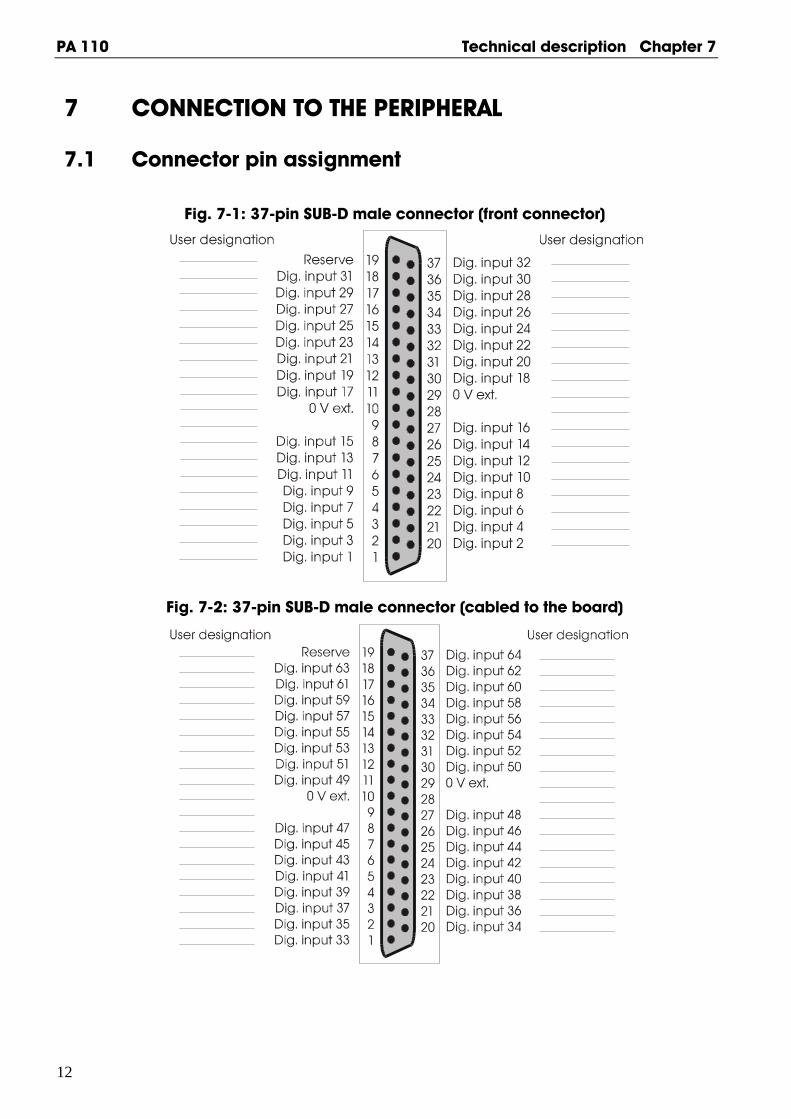
Fig. 7-1: 37-pin SUB-D male connector (front connector)
Fig. 7-2: 37-pin SUB-D male connector (cabled to the board)
Technical description Chapter 7 PA 110
13
7.2 Connection principle
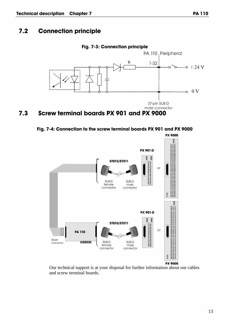
Fig. 7-3: Connection principle
7.3 Screw terminal boards PX 901 and PX 9000
Fig. 7-4: Connection to the screw terminal boards PX 901 and PX 9000
Our technical support is at your disposal for further information about our cablesand screw terminal boards.

PA 110 Technical description Chapter 8
14
8 FUNCTIONS8.1 Board description
The board PA 110 is intended for parallel data input through 64 input channels.The signal inputs are organised into 8 groups of 8 bits.All input channels comply with the industry norm: + 24 V for logical „1“.
The system sides and the peripheral sides are optically isolated.All inputs are isolated and filtered through optical couplers.Each input channel has a go line to the front connector.All inputs use the same return line.
Through the optical isolation, disturbances from the peripheral side to thesystem bus side are avoided. In addition, all inputs are filtered through a RCfilter.The optical coupler inputs have a maximum load of 24 mA.To avoid damage to the optical coupler through voltage reversal, a diode isconnected antiparallel to the LED of the optical coupler.In order to achieve a high dynamic and switching threshold of the input signals,a Z diode is present on each input line.
The board does not require any software initialisation. It can be operatedimmediately after applying the operating voltage. Data transfer between theCPU and the peripherals occurs through buffers.
The address decoding relates to the 64 kB I/O address space.The 3 lower address bits are decoded for the selection of 8 blocks of 8 channels.The higher address bits are compared with the jumper configuration on theboard.If they are identical, the board is enabled.The control logic takes over the co-ordination between board and PC.

Technical description Chapter 9 PA 110
15
9 STANDARD SOFTWARE
9.1 Introduction
IMPORTANT!Note the following conventions in the text:
Function: "i_PA110_SetBoardInformation"Variable ui_Address
Table 9-1: Type Declaration for Dos and Windows 3.1X
Borland C Microsoft C BorlandPascal
MicrosoftVisual Basic
Dos
MicrosoftVisual Basic
Windows
VOID void void pointer any
BYTE unsigned char unsigned char byte integer integer
INT int int integer integer integer
UINT unsigned int unsigned int word long long
LONG long long longint long long
PBYTE unsigned char * unsigned char * var byte integer integer
PINT int * int * var integer integer integer
PUINT unsigned int * unsigned int * var word long long
PCHAR char * char * var string string string
PA 110 Technical description Chapter 9
16
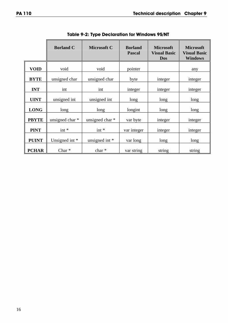
Table 9-2: Type Declaration for Windows 95/NT
Borland C Microsoft C BorlandPascal
MicrosoftVisual Basic
Dos
MicrosoftVisual Basic
Windows
VOID void void pointer any
BYTE unsigned char unsigned char byte integer integer
INT int int integer integer integer
UINT unsigned int unsigned int long long long
LONG long long longint long long
PBYTE unsigned char * unsigned char * var byte integer integer
PINT int * int * var integer integer integer
PUINT Unsigned int * unsigned int * var long long long
PCHAR Char * char * var string string string
Technical description Chapter 9 PA 110
17
9.2 Software functions
9.2.1 Address
1) i_PA110_SetBoardAddress (...)
Syntax:<Return value> = i_PA110_SetBoardAddress (UINT_ ui_Address,
PBYTE_ pb_BoardHandle)
Parameters:- Input:
UINT ui_Address Base address of the PA 110- Output:
PBYTE pb_BoardHandle Handle1) of the PA 110 to use thefunctions of the board
Task:Stores the base address.A handle is returned to the user which allows him/her to use the following functions.With handles several boards can be operated.
Return value: 0: No error-1: Base address already used-2: No handle is available for the board (up to 10 handles can be used)
2) i_PA110_CloseBoardHandle
Syntax:<Return value> = i_PA110_CloseBoardHandle (BYTE b_BoardHandle)
Parameters:- Input:
BYTE b_BoardHandle Handle of board PA 110- Output:
No output signal has occurred.
Task:Releases the board handle. Blocks the access to the board.
Return value:0: No error-1: The handle parameter of the board is wrong
1 Identification number of the board

PA 110 Technical description Chapter 9
18
9.2.2 Digital input channels
1) i_PA110_Read1DigitalInput (...)
Syntax :<Return value> = i_PA110_Read1DigitalInput (BYTE_ b_BoardHandle,
BYTE_ b_Channel, PBYTE_ pb_ChannelValue)
Parameters:- Input:
BYTE b_BoardHandle Handle of board PA 110BYTE b_Channel Number of the input channel to be read
(1 to 64)- Output:
PBYTE pb_ChannelValue State of the digital input channel0 -> low1 -> high
Task:Indicates the state of an input. The variable b_Channel passes the input channel to beread (1 to 64). A value is returned with the variable pb_ChannelValue : 0 (low) or 1(high).
Return value:0: No error-1: The handle parameter of the board is wrong-2: The input number is not between 1 and 32

Technical description Chapter 9 PA 110
19
2) i_PA110_Read8DigitalInput (...)
Syntax:<Return value> = i_PA110_Read8DigitalInput (BYTE b_BoardHandle,
BYTE b_Port, PBYTE pb_PortValue)
Parameters:- Input:
BYTE b_BoardHandle Handle of the PA 110BYTE b_Port Number of the input port to be read
(1 or 8)- Output:
PBYTE pb_PortValue State of the digital input port (0 to 255)
Task:Indicates the state of an 8-bit port. The variable b_Port passes the port to beread (1 or 4). A value is returned with the variable pb_PortValue .
Example:b_Port = 1pb_PortValue = 55 Hex
A voltage is present on the input channels 1, 3, 5, 7A voltage is not present on the input channels 2, 4, 6, 8.
Return value:0: No error-1: Handle parameter of the board is wrong-2: The parameter port number is wrong (parameter 1 to 8)

PA 110 Technical description Chapter 9
20
3) i_PA110_Read16DigitalInput (...)
Syntax:<Return value> = i_PA110_Read16DigitalInput (BYTE b_BoardHandle,
BYTE b_Port PLONG pl_InputValue)
Parameters:- Input:
BYTE b_BoardHandle Handle of the PA 110BYTE b_Port Number of the 16-bit input port to be read
(1 or 4)- Output:
PLONG pl_InputValue State of the digital input channels of bothports (0 to 65535)
Task:Indicates the state of a 16-bit port. The variable b_Port passes the port to be read(1 to 4). A value is returned with the variable pl_InputValue
Example:Parameterb_Port = 1pl_InputValue = 5555 Hex
A voltage is present on the input channels 1, 3, 5, 7, 9, 11, 13, 15 .A voltage is not present on the input channels 2, 4, 6, 8, 10, 12, 14, 16.
Return value:0: No error-1: The handle parameter of the board is wrong-2: The parameter port number is wrong (Parameter 1 to 4)
Technical description Chapter 9 PA 110
21
4) i_PA110_Read32DigitalInput (...)
Syntax:<Return value> = i_PA110_Read32DigitalInput (BYTE b_BoardHandle,
BYTE b_Port, PLONG pl_InputValue)
Parameters:- Input:
BYTE b_BoardHandle Handle of board PA 110BYTE b_Port Number of the 16-bit input port to be read
(1 or 2)- Output:
PLONG pl_InputValue State of the digital input channels of both ports (0 to 232)
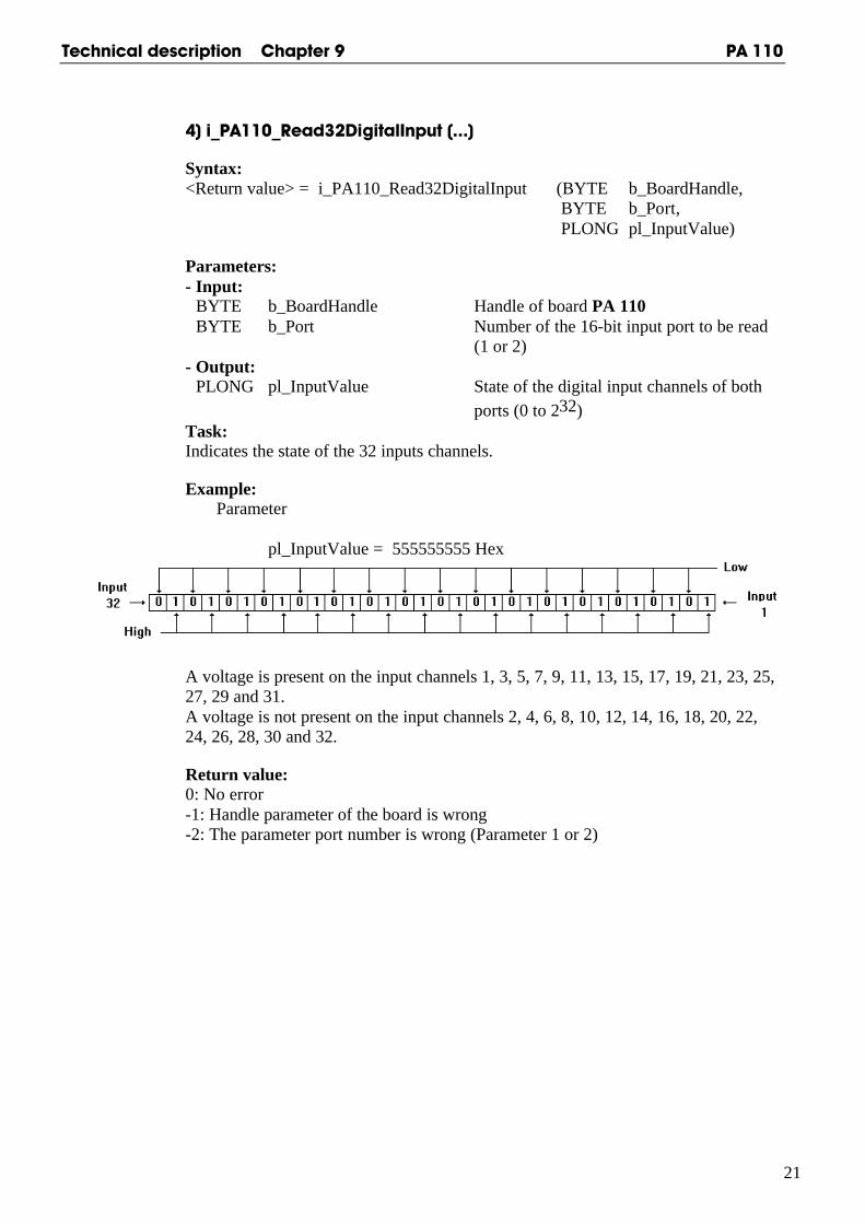
Task:Indicates the state of the 32 inputs channels.
Example:Parameter
pl_InputValue = 555555555 Hex
A voltage is present on the input channels 1, 3, 5, 7, 9, 11, 13, 15, 17, 19, 21, 23, 25,27, 29 and 31.A voltage is not present on the input channels 2, 4, 6, 8, 10, 12, 14, 16, 18, 20, 22,24, 26, 28, 30 and 32.
Return value:0: No error-1: Handle parameter of the board is wrong-2: The parameter port number is wrong (Parameter 1 or 2)