Technical Specs: Hitachi DS1836S1 Scroll Compressor - … · Keep the lead wires away from the...
32
Specifications No. C-0000 15-Apr.-2009 CUSTOMER: COMPRESSOR SPECIFICATIONS Compressor type :Scroll Compressor (Involute type) Refrigerant :R404A Power source :1Ph, 220 - 240V, 50Hz Model Name Nominal Capacity [ W ] Motor Rated Output [ W ] ([HP]) DS1836S1 2,440 1,800 (2.5) We acknowledge the receipt of this copy. Please return this compressor specifications after confirming the contents. If you do not return this copy by the above date, we will assume that you have checked the contents. Hitachi Appliances, Inc. Compressor Department APPD. CHKD. DWN. The Specifications in this bulletin are subject to change without notice, in order that HITACHI may bring the latest innovations to our customers. NOTE
Transcript of Technical Specs: Hitachi DS1836S1 Scroll Compressor - … · Keep the lead wires away from the...

Specifications No. C-0000 15-Apr.-2009
CUSTOMER:
COMPRESSOR SPECIFICATIONS
Compressor type :Scroll Compressor (Involute type)
Refrigerant :R404A Power source :1Ph, 220 - 240V, 50Hz
Model Name Nominal Capacity [ W ]
Motor Rated Output [ W ] ([HP])
DS1836S1 2,440 1,800 (2.5)
We acknowledge the receipt of this copy.
Please return this compressor specifications after confirming the contents. If you do not return this copy by the above date, we will assume that you have checked the contents.
Hitachi Appliances, Inc. Compressor Department APPD. CHKD. DWN.
The Specifications in this bulletin are subject to change without notice, in order that HITACHI may bring the latest innovations to our customers.
NOTE

PAGE:1
SAFETY PRECAUTION
Read and understand all of the safety precautions in this manual before operating the product.
These precautions are intended to ensure safe and correct operation of the product and
to prevent injury to the operator and other persons and damage to the product.
Observe these precautions strictly.
The following symbols indicate the presence of potentially hazardous conditions.
WARNING
Be sure to perform the operation.
Disconnect the power cable from the electrical outlet.
Connect the grounding wire.
Prohibit.
WARNING
Provide the refrigerating cycle unit with adequate electrical grounding. Incomplete grounding
could result in electrical shock hazards in the event of troubles and current leakage.
Connect a fuse or a leak circuit breaker to the main circuit
to avoid electrical shock hazards or fire in the event of troubles and current leakage.
Check to see that the main power is turned off, before repairing,
to avoid electrical shock hazards in case of touching the terminals.
This symbol indicates a potentially hazardous situation which, if not avoided,could result in death or serious injury.
This symbol indicates a potentially hazardous situation which, if not avoided,may result in minor or moderate injury or property damage accidents to the product.It may also be used to alert against unsafe practices.
The meanings of the graphic symbols in text are shown bellow.
Lead wire insulation deterioration (thermal deterioration) could result in electrical shock hazards,short-circuiting, or fire.
Keep the lead wires away from the surface of the compressor or the piping.
Lead wire insulation deterioration (thermal deterioration) could result in electrical shock hazards,short-circuiting, or fire.
CAUTION
Measure the temperature of the hermetic terminals of the compressor and then connect theappropriate lead wires.

PAGE:2
Do NOT use this compressor for air compression,which avoids overheating of the compressor that could cause burns or fire.
Incomplete electrical conduction of the hermetic terminals may cause troubles or fire.
Keep the lead wires away from any rotational parts like fans or any vibrational parts likepiping.
Lead wire insulation deterioration due to vibration or friction could result in electrical shockhazards, short-circuiting, or fire.
Do NOT make the compressor self-evacuated during operation, which avoids overheating thecompressor that could cause burns or fire.
Do NOT touch the surface of the compressor with empty hands, which avoids burns.The surface is very hot during operation and immediately after it has stopped.
Do NOT view the inspection window of the compressor for internal observation directly.Use a video camera or other suitable equipment to avoid serious injury owing to explosionof the inspection window or blowout of the refrigerant.
Wear protective goggles during repairs to avoid serious injury owing to explosionof piping or blowout of the refrigerant.
Do NOT install the compressor in a humid place or locations exposed to water. Do NOT dip itinto water or spray it with water. In case of using the sound insulation material to enclose thecompressor, which is highly hygroscopic, that material must NOT absorb water. Insulationdeterioration causes electrical shock hazards, current leakage, short-circuiting, or explosionowing to corrosion.
Attach the specified cover to the hermetic terminals of the compressor by the specified methodto prevent entry of dirt.
Do NOT apply electrical pulse to the compressor while its inside is maintained in a vacuum.It avoids insulation failure inside the compressor, which may result in electrical shock hazards,current leakage, or fire.
Store the compressor in clean and dry environment. Insulation failure of the hermetic terminalsof the compressor may result in electrical shock hazards or current leakage. Corrosion of thecompressor surface may result in explosion. Blowout of the refrigerant may result in burns.
In case of attaching cluster terminals, the PTC starter, receptacle terminals, or otherelectrical parts to the hermetic terminals of the compressor, those parts must NOT beobliquely connected or twisted after connections, which avoids reducing fastening force of theterminals. Incomplete electrical conduction of the hermetic terminals may cause troubles orfire.
CAUTION
SCROLL COMPRESSOR SPECIFICATIONS PAGE: 3
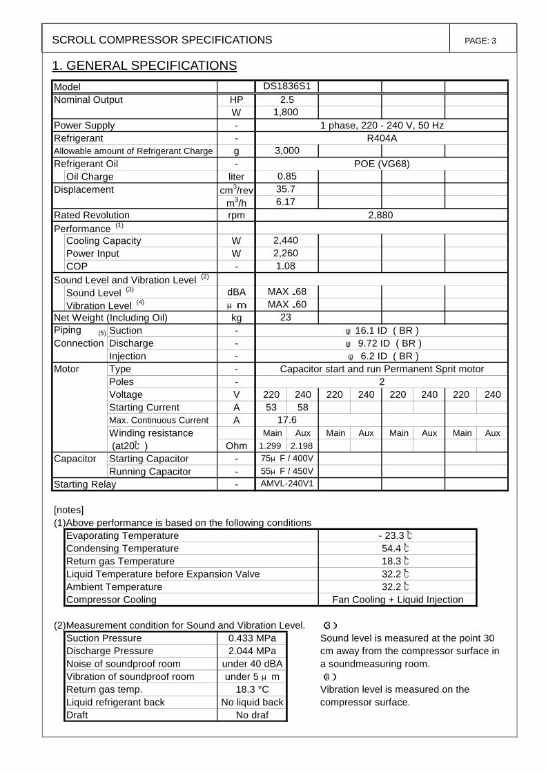
1. GENERAL SPECIFICATIONS
ModelNominal Output HP
WPower Supply - 1 phase, 220 - 240 V, 50 HzRefrigerant - R404AAllowable amount of Refrigerant Charge gRefrigerant Oil - POE (VG68)
Oil Charge literDisplacement cm3/rev
m3/hRated Revolution rpm 2,880Performance (1)
Cooling Capacity WPower Input WCOP -
Sound Level and Vibration Level (2)
Sound Level (3) dBAVibration Level (4) μm
Net Weight (Including Oil) kgPiping (5) Suction - φ16.1 ID ( BR )Connection Discharge - φ 9.72 ID ( BR )
Injection - φ 6.2 ID ( BR )Motor Type - Capacitor start and run Permanent Sprit motor
Poles - 2Voltage V 220 240 220 240 220 240 220 240Starting Current A 53 58Max. Continuous Current AWinding resistance Main Aux Main Aux Main Aux Main Aux (at20℃) Ohm 1.299 2.198
Capacitor Starting Capacitor -Running Capacitor -
Starting Relay -
[notes](1)Above performance is based on the following conditions
Evaporating Temperature - 23.3 ℃Condensing Temperature 54.4 ℃Return gas Temperature 18.3 ℃Liquid Temperature before Expansion Valve 32.2 ℃Ambient Temperature 32.2 ℃Compressor Cooling Fan Cooling + Liquid Injection
(2)Measurement condition for Sound and Vibration Level. (3)Suction Pressure 0.433 MPa Sound level is measured at the point 30Discharge Pressure 2.044 MPa cm away from the compressor surface inNoise of soundproof room under 40 dBA a soundmeasuring room.Vibration of soundproof room under 5 μm (4)
Return gas temp. 18.3 °C Vibration level is measured on theLiquid refrigerant back No liquid back compressor surface.Draft No draf
3,000
0.85
MAX.60MAX.68
75μF / 400V55μF / 450VAMVL-240V1
17.6
2,4402,2601.08
23
35.76.17
2.51,800
DS1836S1
SCROLL COMPRESSOR SPECIFICATIONS PAGE: 4
(5)Connection Type BR : Brazing, RL : Rotalock, FL : Flange, FR : Flare
(6)Scope of Supply
1) Compressor Assembly Charged with Refrigerant Oil and Nitrogen Gas. 2) The companion connections shall be provided by others.
The other specifications 1. Hermetic terminal : 1/4"quick connect type 2. Space volume of inner shell : 2,000 mL 3. Motor Insulation grade : E 4. Approval voltage range rated voltage ±10% 5. Starting performance
The minimum starting voltage shall be as TABLE 1. (see note 7) under the following conditions.
(1) The starting pressure should be between the suction and discharge of the compressor was balanced and adjusted as shown in the TABLE 1.
(2) The temperature of compressor case was adjusted to 20 °C or higher at the starting conditions.
TABLE 1 Starting conditions
Motor temperature Ambient
temp. Pressure Minimum starting voltage{V2}
Cold-starting Cold state (Room temperature) 20°C 1.35 MPa 85% of rated voltage
Hot-starting<Standard> Hot state after operated under standard condition 32.2 °C 1.29 MPa 85% of rated voltage
Hot-Starting<Overload> Hot state after operated overload condition. 43 °C 1.42 MPa 90% of rated voltage
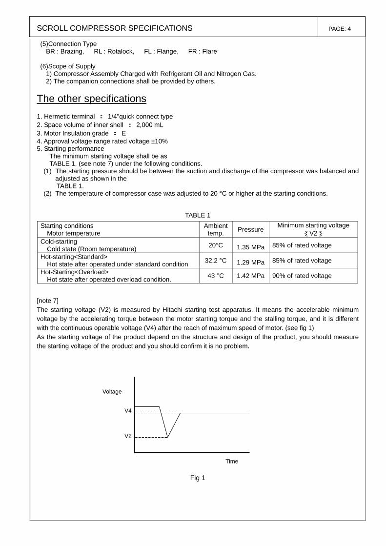
[note 7] The starting voltage (V2) is measured by Hitachi starting test apparatus. It means the accelerable minimum voltage by the accelerating torque between the motor starting torque and the stalling torque, and it is different with the continuous operable voltage (V4) after the reach of maximum speed of motor. (see fig 1) As the starting voltage of the product depend on the structure and design of the product, you should measure the starting voltage of the product and you should confirm it is no problem.
Fig 1
Voltage
Time
V4
V2
SCROLL COMPRESSOR SPECIFICATIONS PAGE: 5
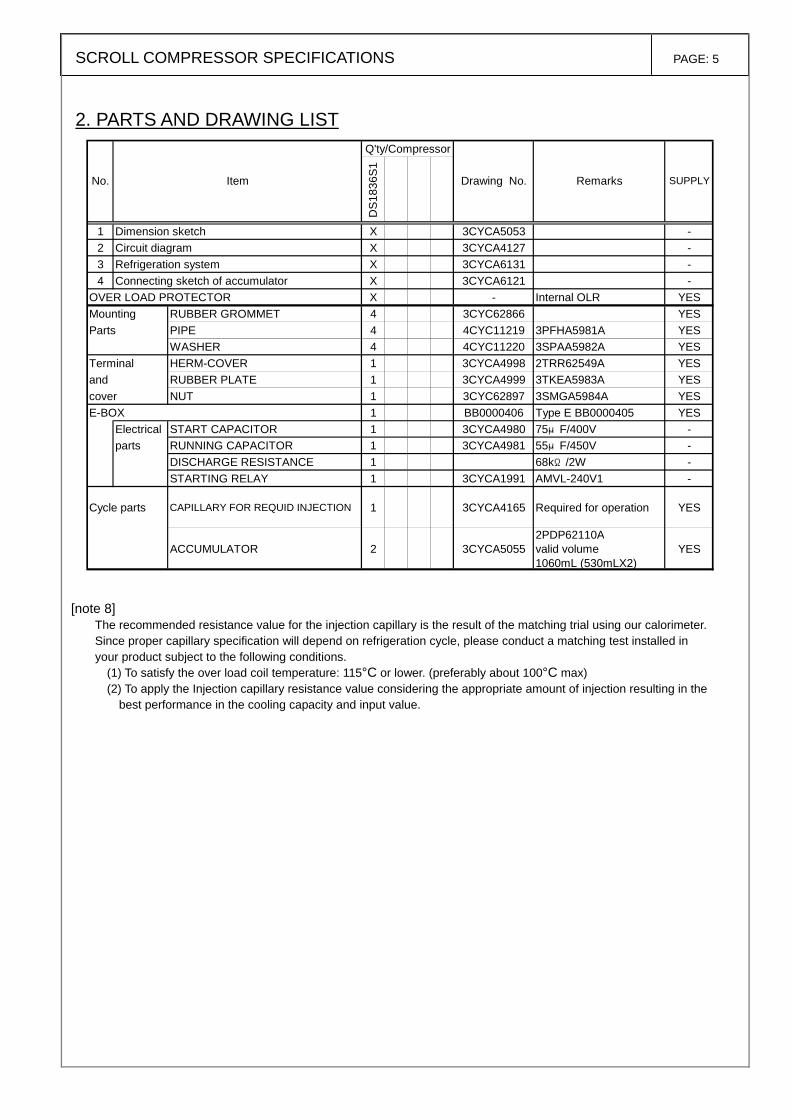
2. PARTS AND DRAWING LIST
Q'ty/Compressor
DS1
836S
1
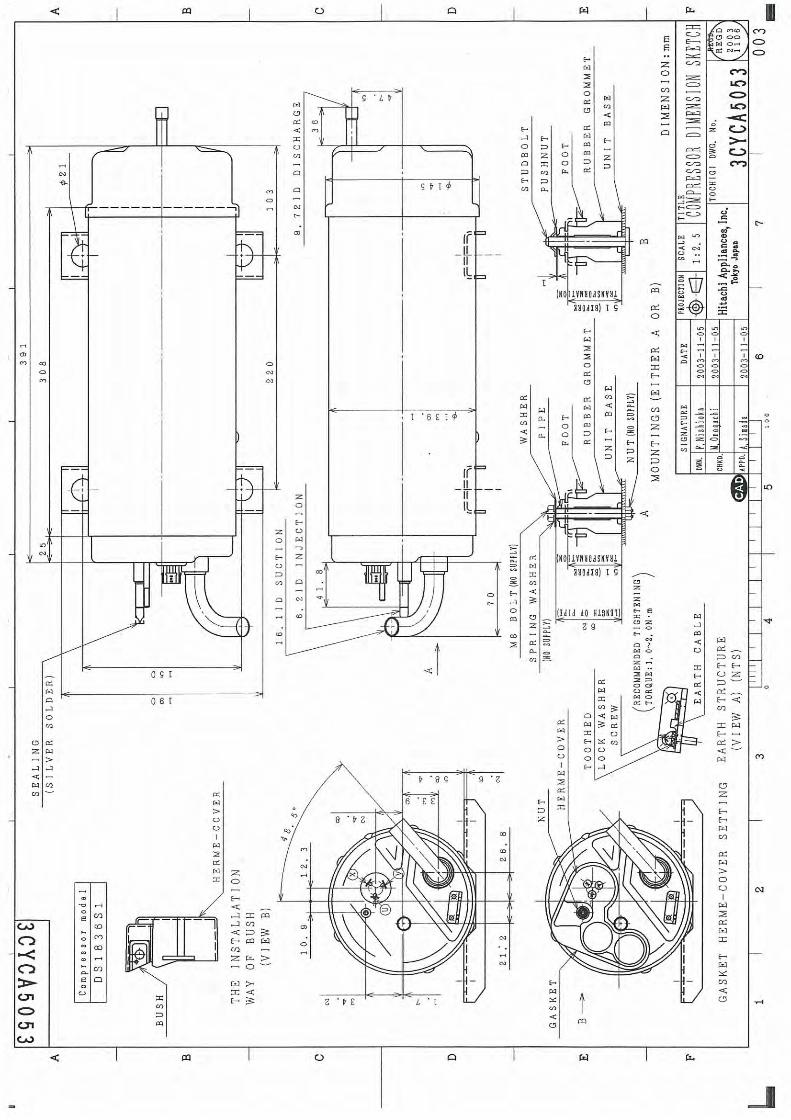
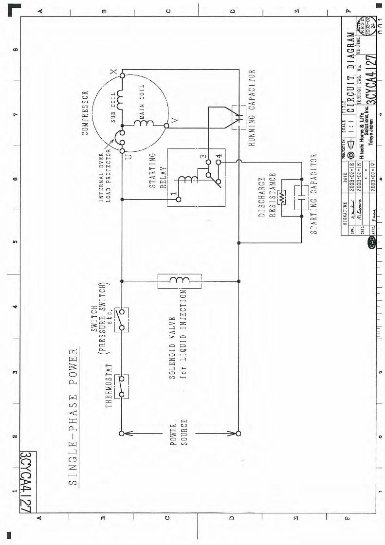
1 Dimension sketch X 3CYCA5053 -2 Circuit diagram X 3CYCA4127 -3 Refrigeration system X 3CYCA6131 -4 Connecting sketch of accumulator X 3CYCA6121 -
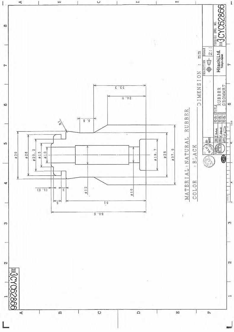
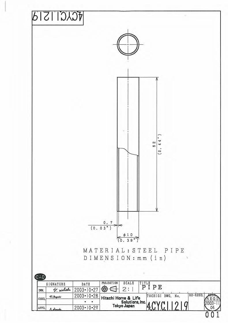
OVER LOAD PROTECTOR X - Internal OLR YESMounting RUBBER GROMMET 4 3CYC62866 YESParts PIPE 4 4CYC11219 3PFHA5981A YES
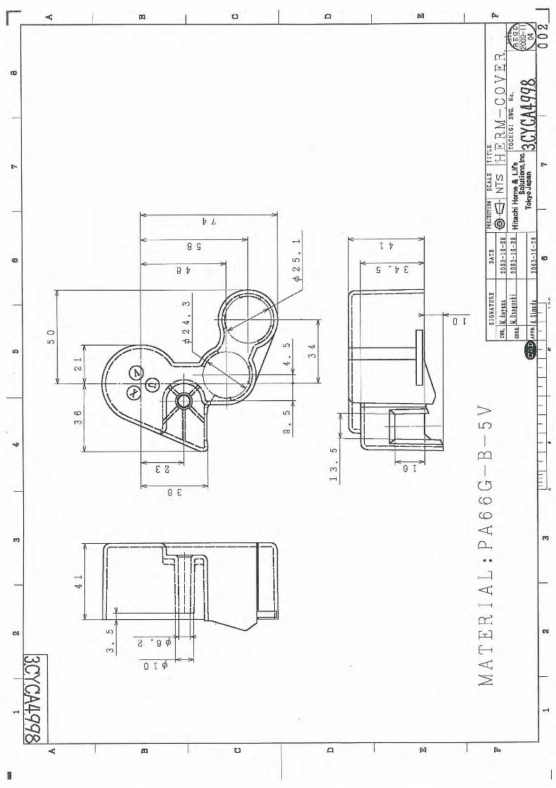
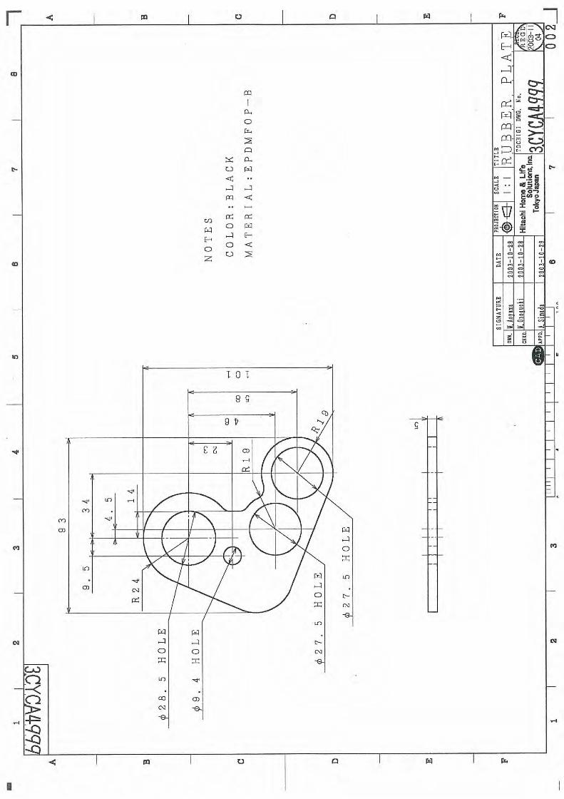
WASHER 4 4CYC11220 3SPAA5982A YESTerminal HERM-COVER 1 3CYCA4998 2TRR62549A YESand RUBBER PLATE 1 3CYCA4999 3TKEA5983A YEScover NUT 1 3CYC62897 3SMGA5984A YESE-BOX 1 BB0000406 Type E BB0000405 YES
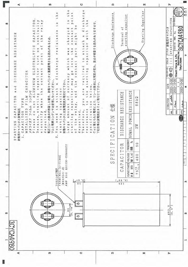
Electrical START CAPACITOR 1 3CYCA4980 75μF/400V -parts RUNNING CAPACITOR 1 3CYCA4981 55μF/450V -
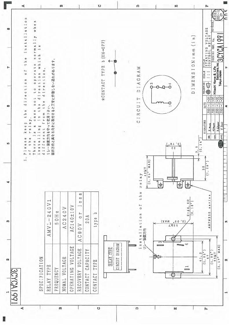
DISCHARGE RESISTANCE 1 68kΩ/2W -STARTING RELAY 1 3CYCA1991 AMVL-240V1 -
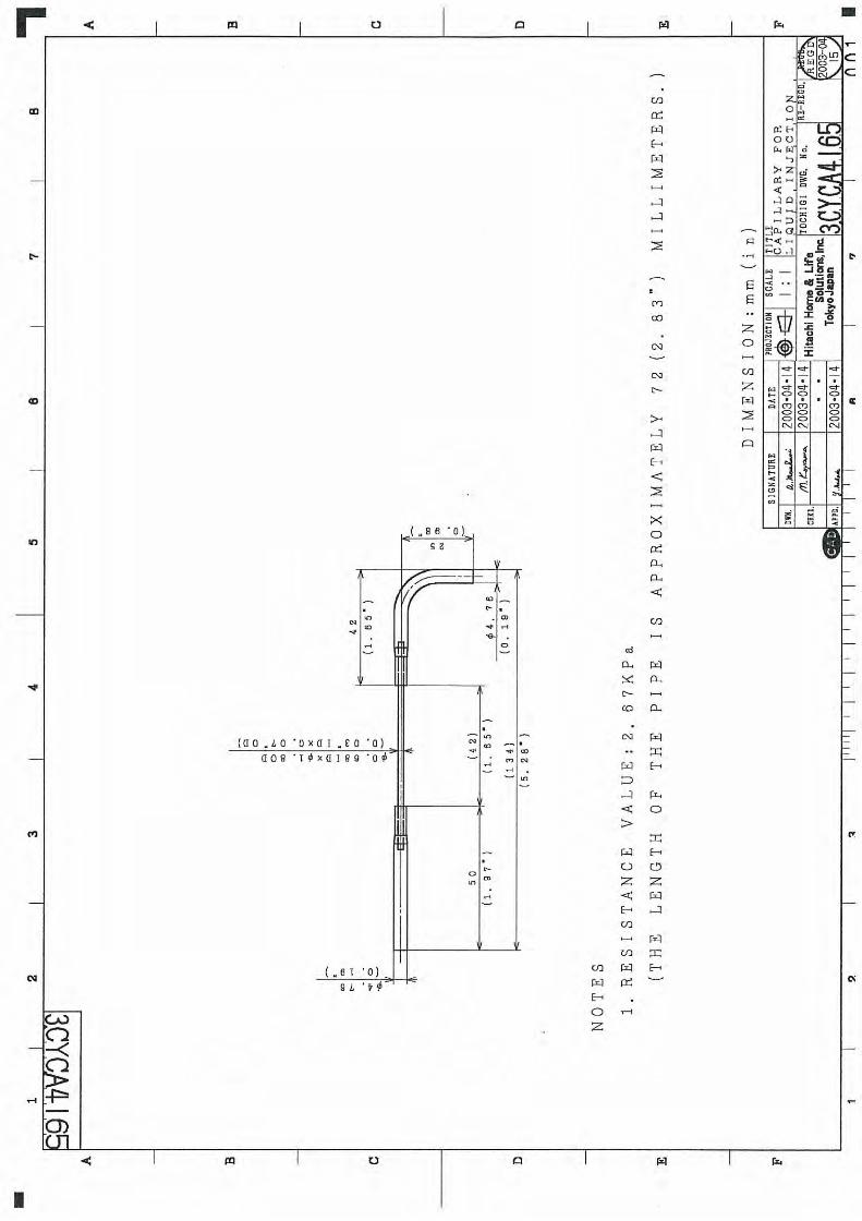
Cycle parts CAPILLARY FOR REQUID INJECTION 1 3CYCA4165 Required for operation YES
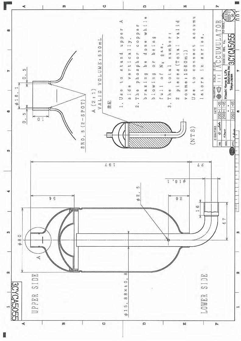
ACCUMULATOR 2 3CYCA50552PDP62110Avalid volume1060mL (530mLX2)
YES
SUPPLYNo. Drawing No. RemarksItem
[note 8] The recommended resistance value for the injection capillary is the result of the matching trial using our calorimeter. Since proper capillary specification will depend on refrigeration cycle, please conduct a matching test installed in your product subject to the following conditions.
(1) To satisfy the over load coil temperature: 115°C or lower. (preferably about 100°C max) (2) To apply the Injection capillary resistance value considering the appropriate amount of injection resulting in the
best performance in the cooling capacity and input value.

SCROLL COMPRESSOR SPECIFICATIONS PAGE: 6
3. APPLICATION RANGE 1. Scope
This specification is applied to HITACHI scroll compressor.
2. Common specification of compressor
2.1 Appearance
The surface of compressor shall be painted black and has no cracks, dents, peeling, or significant rust.
2.2 Marking
Model name and production date should be shown on the surface of compressor. The compressor
containing refrigeration oil and dried N2 gas has one white circle mark and one yellow circle mark.
2.3 Insulation distances
The Electrical Appliance and Material Safety Law (JAPAN) and JIS C9621 and UL984 are applied.
2.4 Insulation resistance
Measurement should be above 10 MΩ between charged parts and non-charged parts by 500 V insulation
resistance meter at normal temperature and normal humidity.
2.5 Dielectric Withstand Voltage Test
After 2.4 test, 1500 V A/C 50 Hz or 60 Hz is applied between live parts and dead metal parts continuously
for one minute by gradual rise of voltage. In case of 1800 V, duration is one second instead of one minute.
2.6 Pressure Test
Pressure test should be done by JIS B8620 and UL984.
2.7 Dryness
Residual water content is below 0.20mL by the cold trap method described below:
Table 2. Cold trap method Item Condition
Furnace 146 ± 3 °C Pre-heat hour No pre-heat Hour of taking water (Preheating time excluded) 6 hours Degree of vacuum (Continuous vacuum) Below 133 Pa Solvent for cold bath Methanol Coolant for cold bath Dry ice
2.8 Cleanliness
Drain the refrigerant oil. Pour washing liquid into the compressor. Lay down and roll the compressor and
drain washing liquid. Filtrate by filter paper. The trapped particles should be under 70 mg.
2.9 Airtight test pressure
3.24 MPa
3. System design limitations
3.1 Observance of the specification
The compressor should always be operated under the condition set forth in this specification and it should
not be operated under any other specifications. Accessories should also be used as specified. In addition,

SCROLL COMPRESSOR SPECIFICATIONS PAGE: 7
the specified parts should be used during servicing. Fuse or circuit breaker should be connected to main
electric circuit.
3.2 Power source voltage
Voltage applied to the hermetic terminal should be within the range mentioned in this specification.
In the case of 3 phases electric power source, the unequilibrium of the voltage between each phase must
be used within 3%.
Furthermore, in the case of 3 phases electric
power source, the wiring for reverse rotating
caused by two phases replacement must not be used. The damage of the compressor caused by the
reverse rotating is out of warranty. If wiring may cause reverse rotating, the direction relay listed on the list
of equipment and materials must be connected.
3.3 Operating temperatures and pressures
Suction pressure and discharge pressure should be within the range of FIG.4. (page 14)
The difference between discharge pressure and suction pressure must be more than the pressure of
table 3.
TABLE 3
Model DS1836S1
Discharge pressure-Suction pressure (MPa) 0.61
The operating temperatures and pressures of a compressor should be within the range shown in the
following section 3.4 - 3.7.
3.4 Compressor case bottom temp
99℃ or below and 6 degrees higher then condensing temperature.
3.5 Motor winding temp. (Measured by the resistance method)
(1) Standard load condition
Rated voltage ; 105°C MAX
Rated voltage ±10% ; 115°C MAX
(2) Over condition
Rated voltage ±7.5% ; 115°C MAX
3.6 Suction pipe temp.
Higher than outlet pipe of evaporator
3.7 Discharge pipe temp.
Lower than 110°C at 300mm away from compressor surface.
[note 9]
Overload condition should not be continuous.
[note 10]
The end of thermocouple should be soldered on the discharge pipe surface, and the soldered place is
covered by urethane foam insulation preventing the influence of airflow, when you measure the discharge
pipe temperature.
Unequilibrium= Max.deviation voltage – Ave.voltage Average voltage
X100(%)
SCROLL COMPRESSOR SPECIFICATIONS PAGE: 8
3.8 Temperature and pressure at blocked fan condition
Don’t operate compressor at blocked fan condition. To avoid problem of fire, discharge pressure should be
under 4.22MPa[abs]. Under stable condition, Confirm the motor winding temperature should be not more
then 165°C (average) or 190°C MAX (highest).
3.9 Compressor ambient temperature
The compressor should be operated within the ambient temperature range that satisfies the motor winding
temperature requirements shown previously Section 3.3. This compressor should be used in the place that
the ambient temperature is above -10 °C. Please confirm the starting of compressor, when the temperature
of compressor surface is -10 °C.
Under -10°C ambient temperature, in the case that the temperature of compressor surface is above -10°C
by the crankcase beating etc, you can use the compressor if the starting is possible.
3.10 Operating and Shut-off interval
The compressor should not be started/stopped more than 6 times per hour. The compressor should be
operated continuously at least for 5 minutes after being turned on. Allow a minimum of 3 minutes shut-off
time before restarting.
Compressor should be started on the condition that pressure status of high/low pressure sides is balanced.
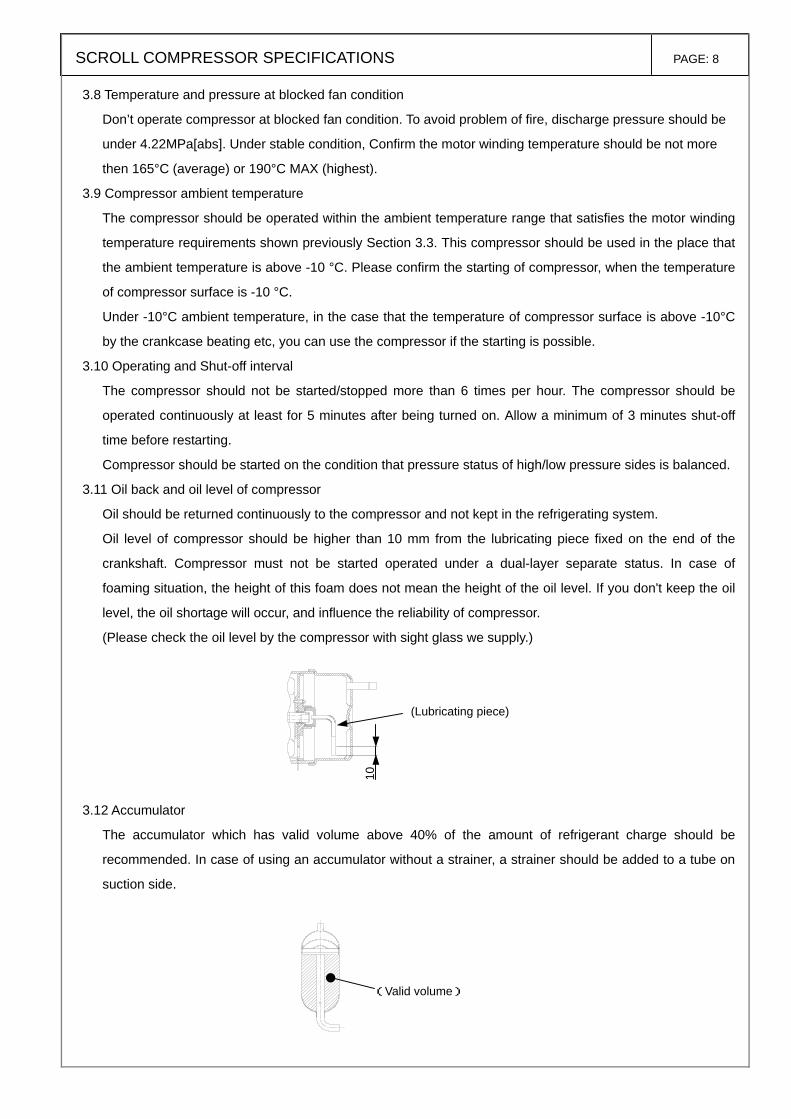
3.11 Oil back and oil level of compressor
Oil should be returned continuously to the compressor and not kept in the refrigerating system.
Oil level of compressor should be higher than 10 mm from the lubricating piece fixed on the end of the
crankshaft. Compressor must not be started operated under a dual-layer separate status. In case of
foaming situation, the height of this foam does not mean the height of the oil level. If you don't keep the oil
level, the oil shortage will occur, and influence the reliability of compressor.
(Please check the oil level by the compressor with sight glass we supply.)
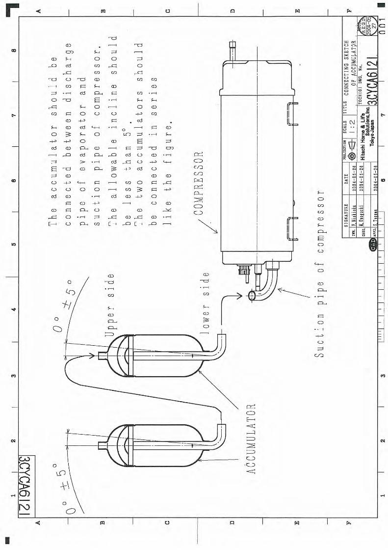
3.12 Accumulator
The accumulator which has valid volume above 40% of the amount of refrigerant charge should be
recommended. In case of using an accumulator without a strainer, a strainer should be added to a tube on
suction side.
(Valid volume)
10
(Lubricating piece)
SCROLL COMPRESSOR SPECIFICATIONS PAGE: 9
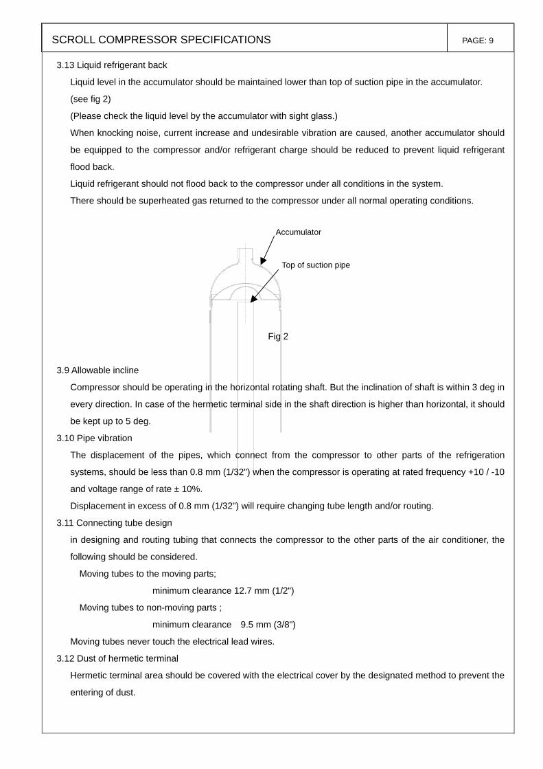
3.13 Liquid refrigerant back
Liquid level in the accumulator should be maintained lower than top of suction pipe in the accumulator.
(see fig 2)
(Please check the liquid level by the accumulator with sight glass.)
When knocking noise, current increase and undesirable vibration are caused, another accumulator should
be equipped to the compressor and/or refrigerant charge should be reduced to prevent liquid refrigerant
flood back.
Liquid refrigerant should not flood back to the compressor under all conditions in the system.
There should be superheated gas returned to the compressor under all normal operating conditions.
Fig 2
3.9 Allowable incline
Compressor should be operating in the horizontal rotating shaft. But the inclination of shaft is within 3 deg in
every direction. In case of the hermetic terminal side in the shaft direction is higher than horizontal, it should
be kept up to 5 deg.
3.10 Pipe vibration
The displacement of the pipes, which connect from the compressor to other parts of the refrigeration
systems, should be less than 0.8 mm (1/32") when the compressor is operating at rated frequency +10 / -10
and voltage range of rate ± 10%.
Displacement in excess of 0.8 mm (1/32") will require changing tube length and/or routing.
3.11 Connecting tube design
in designing and routing tubing that connects the compressor to the other parts of the air conditioner, the
following should be considered.
Moving tubes to the moving parts;
minimum clearance 12.7 mm (1/2")
Moving tubes to non-moving parts ;
minimum clearance 9.5 mm (3/8")
Moving tubes never touch the electrical lead wires.
3.12 Dust of hermetic terminal
Hermetic terminal area should be covered with the electrical cover by the designated method to prevent the
entering of dust.
Accumulator
Top of suction pipe

SCROLL COMPRESSOR SPECIFICATIONS PAGE: 10
3.13 Rotation direction of compressor
Connect compressor terminals as specified in circuit diagram. Reverse operation will result pump
breakdown.
3.14 Internal over load protector (OLP).
Although an OLP that Hitachi selected is installed in this compressor, the current and temperature may not
be appropriated for the structure or design of the unit in which the compressor will be mounted.
Unit-mounting matching tests should therefore be conducted and checks should be performed to ensure
that the requirements listed as item (1) and (2) below are satisfied.
If the OLP could not satisfy the requirements in the unit test, this should be notified to Hitachi and then
after reselection through mutual discussions on the optimum OLP for the unit, unit-mounting test should be
performed again.
(1) OLP non-operating test:
The provisions of section 3.3 should be satisfied.
(2) OLP operating test (trouble-assuming test):
When the compressor ambient temperature is 23 ± 2 °C, the winding temperature should not exceed
190 °C at rated voltage ± 6%, and when the compressor ambient temperature is 0 ± 2 °C, the winding
temperature should not exceed 240 °C at rated voltage -15%, and when the compressor ambient
temperature is 40 ± 2 °C.
Supplementary description;
[1] Exception for the value in transitional states.
[2] The motor winding temperature should be
measured using the resistance method.
[3] The tests should be terminated when the total
number of OLP operations or the total OLP
operating time reaches 10,000 (time) or 15
days, which ever comes first. Fig 3
4. Process limitations
4.1 The degree of vacuum in the refrigerating system should be less than 133 Pa(abs) at room temperature
just before charging refrigerant. The reference quantity of water in the refrigerating system is less than 0.2g.
The quantity of water the cycle in operation is to make to the 40 ppm following in the refrigerating cycle by
using the suitable dryer that does not contain ACTIVATED ALUMINA.
4.2 The structure of cycle constitution or drier should be done so that the powder of the drying material does
not come out throughout the cycle.
4.3 The weight of foreign particles on the inside surface of the heat exchange tubes should be less than
0.05 g/m2. This value means the weight of foreign particles filtered after washing inside surface of the heat
exchange tubes with alkali.
Metallic dust should not be permitted to enter the refrigerating system.
OLP rest temp.
Max temp. of winding
OLP operating temp.
Win
ding
tem
p.
time

SCROLL COMPRESSOR SPECIFICATIONS PAGE: 11
4.4 Eliminate all system contaminates such as trichloroethane, alkalis, soaps, acids, oil and washing fluid used
in machining the heat exchanger.
4.5 Always purge the compressor with dry nitrogen during assembly of the system.
4.6 The quantity and kind of contamination (the process materials) in the cycle should be grasped and
managed. Carry on reliability test that Input contamination a lot than anticipated contamination quantity.
4.7 The motor winding temperatures should be less than 149 °C in process of manufacturing the refrigerating
system. The temperature of the hermetic terminal body should be less than 177 °C.
4.8 The compressor should be operated for more than 20 seconds within 15 minutes after refrigerant is put into
the system so that proper lubrication of the pump can occur.
5. Miscellaneous
5.1 The pipe and hermetic pins, which are attached to the compressor, should not be bent.
5.2 The compressor should never be operated while under vacuum; otherwise, internal arcing can damage
parts.
5.3 The compressor should not be operated in a method that forms a vacuum and absorbs air.
5.4 The compressor should not be left open to the atmosphere for more than 15 minutes.
5.5 The electric pulse should not be applied to the hermetic terminals when the compressor is under vacuum.
5.6 The compressor should be kept in a clean place with low-moisture.
5.7 The compressor must not be applied for transportation equipment such as automobiles, trains, ships, and
the others.
5.8 The compressor should not be splashed intentionally with water.
5.9 Refrigerant should be charged from the condenser end of the refrigeration system. Never charge
refrigerant to the compressor directly.
5.10 Temperatures within systems during stable compressor operation should not be less than -45 °C to
prevent wax precipitation from the oil.
5.11 The compressor, if dropped, should not be used.
5.12 Compressor mounting
Rubber grommets are designed soft to provide noise isolation and to lessen vibration energy transmission.
Stud bolt should be designed to provide sufficient clearance for noise and vibration isolation and to prevent
compressor from coming off its mount.
5.13 The first starting voltage supplied to the refrigerating system should be more than the starting voltage
mentioned TABLE 1. (page 2)
Because the viscosity of the oil may be high at first starting until the refrigerant dissolves in the oil.
5.14 The compressor should be kept out of a corrosive atmosphere, such as a chemicals storage area.
5.15 The lead wires should be connected to the hermetic terminals without touching the surface of the
compressor.
5.16 The compressor should be used within one year of receipt.
5.17 The failure of refrigeration system components such as the reversing valve, solenoid valve, defrost
mechanism, refrigerant control parts, fan motor, etc. may cause failure of the compressor. Reliability of

SCROLL COMPRESSOR SPECIFICATIONS PAGE: 12
those components should be checked.
A design that insures no leakage during manufacturing and usage should be applied.
5.18 The refrigerating cycle should be grounded.
5.19 The failure of accessory parts (ex. Capacitor) utilized by the customer is not related to Hitachi Appliances,
Inc.
5.20 The person who is directly in charge of setting up the product or repair of the product should be well
instructed to prevent contamination of this product by water or other foreign matters.
When recharging refrigerator, dryer must be changed. And water value should be less than 40 ppm.
5.21 When connecting terminals of the unit to the hermetically sealed terminals of the compressor, the parts
must not be obliquely connected or twisted after connection, fastening force of the terminals would be
reduced.
5.22 Modifications and additions
If modifications or additions are to be made to the items provided for in this specification, both companies
shall immediately report the details of those modifications or additions, together with the reasons for them,
in writing before performing the modifications or additions.
5.23 Occurrence of problems
If problems occur after delivery, both companies shall immediately list those problems. After reporting, a
solution to these problems will be sought and reported.
Hitachi Appliances, Inc. has no obligation duty for the problem in the case that the user didn't obey this
compressor using specification & criteria.
5.24 Term of Validity
This specification shall go into effect from the date that the user signs the specification.
5.25 Submission of this Specification
Hitachi Appliances, Inc. will submit two copies of this specification and the user shall return one copy only
after acknowledging receipt of the specification.
This specification will be kept in the Air Conditioning Systems Design Department of Hitachi Appliances,
Inc.
Hitachi Appliances, Inc.
No. date page revised reason for revision
APPD. CHKD. DWN.CUSTOMER
1
2
3
4
SCROLL COMPRESSOR SPECIFICATIONS PAGE: 13
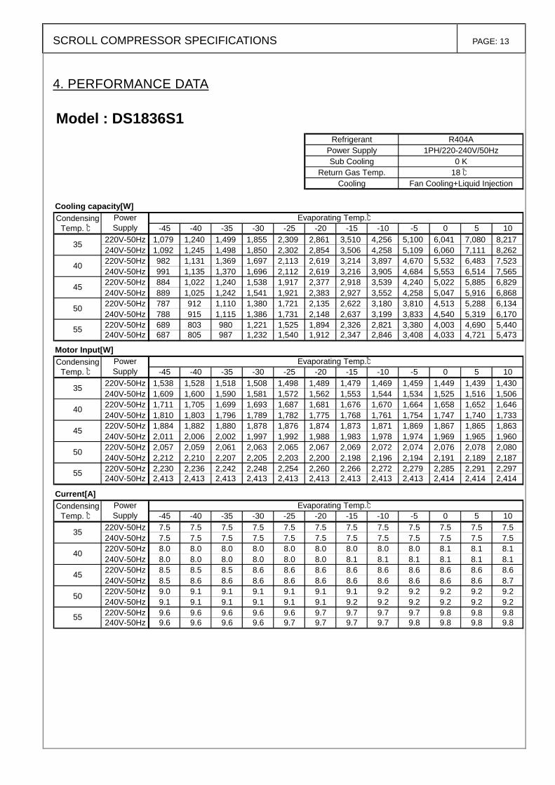
4. PERFORMANCE DATA
Model : DS1836S1Refrigerant R404A
Power Supply 1PH/220-240V/50HzSub Cooling 0 K
Return Gas Temp. 18 ℃Cooling Fan Cooling+Liquid Injection
Cooling capacity[W]Condensing
Temp. ℃ -45 -40 -35 -30 -25 -20 -15 -10 -5 0 5 10220V-50Hz 1,079 1,240 1,499 1,855 2,309 2,861 3,510 4,256 5,100 6,041 7,080 8,217240V-50Hz 1,092 1,245 1,498 1,850 2,302 2,854 3,506 4,258 5,109 6,060 7,111 8,262220V-50Hz 982 1,131 1,369 1,697 2,113 2,619 3,214 3,897 4,670 5,532 6,483 7,523240V-50Hz 991 1,135 1,370 1,696 2,112 2,619 3,216 3,905 4,684 5,553 6,514 7,565220V-50Hz 884 1,022 1,240 1,538 1,917 2,377 2,918 3,539 4,240 5,022 5,885 6,829240V-50Hz 889 1,025 1,242 1,541 1,921 2,383 2,927 3,552 4,258 5,047 5,916 6,868220V-50Hz 787 912 1,110 1,380 1,721 2,135 2,622 3,180 3,810 4,513 5,288 6,134240V-50Hz 788 915 1,115 1,386 1,731 2,148 2,637 3,199 3,833 4,540 5,319 6,170220V-50Hz 689 803 980 1,221 1,525 1,894 2,326 2,821 3,380 4,003 4,690 5,440240V-50Hz 687 805 987 1,232 1,540 1,912 2,347 2,846 3,408 4,033 4,721 5,473
Motor Input[W]Condensing
Temp. ℃ -45 -40 -35 -30 -25 -20 -15 -10 -5 0 5 10220V-50Hz 1,538 1,528 1,518 1,508 1,498 1,489 1,479 1,469 1,459 1,449 1,439 1,430240V-50Hz 1,609 1,600 1,590 1,581 1,572 1,562 1,553 1,544 1,534 1,525 1,516 1,506220V-50Hz 1,711 1,705 1,699 1,693 1,687 1,681 1,676 1,670 1,664 1,658 1,652 1,646240V-50Hz 1,810 1,803 1,796 1,789 1,782 1,775 1,768 1,761 1,754 1,747 1,740 1,733220V-50Hz 1,884 1,882 1,880 1,878 1,876 1,874 1,873 1,871 1,869 1,867 1,865 1,863240V-50Hz 2,011 2,006 2,002 1,997 1,992 1,988 1,983 1,978 1,974 1,969 1,965 1,960220V-50Hz 2,057 2,059 2,061 2,063 2,065 2,067 2,069 2,072 2,074 2,076 2,078 2,080240V-50Hz 2,212 2,210 2,207 2,205 2,203 2,200 2,198 2,196 2,194 2,191 2,189 2,187220V-50Hz 2,230 2,236 2,242 2,248 2,254 2,260 2,266 2,272 2,279 2,285 2,291 2,297240V-50Hz 2,413 2,413 2,413 2,413 2,413 2,413 2,413 2,413 2,413 2,414 2,414 2,414
Current[A]Condensing
Temp. ℃ -45 -40 -35 -30 -25 -20 -15 -10 -5 0 5 10220V-50Hz 7.5 7.5 7.5 7.5 7.5 7.5 7.5 7.5 7.5 7.5 7.5 7.5240V-50Hz 7.5 7.5 7.5 7.5 7.5 7.5 7.5 7.5 7.5 7.5 7.5 7.5220V-50Hz 8.0 8.0 8.0 8.0 8.0 8.0 8.0 8.0 8.0 8.1 8.1 8.1240V-50Hz 8.0 8.0 8.0 8.0 8.0 8.0 8.1 8.1 8.1 8.1 8.1 8.1220V-50Hz 8.5 8.5 8.5 8.6 8.6 8.6 8.6 8.6 8.6 8.6 8.6 8.6240V-50Hz 8.5 8.6 8.6 8.6 8.6 8.6 8.6 8.6 8.6 8.6 8.6 8.7220V-50Hz 9.0 9.1 9.1 9.1 9.1 9.1 9.1 9.2 9.2 9.2 9.2 9.2240V-50Hz 9.1 9.1 9.1 9.1 9.1 9.1 9.2 9.2 9.2 9.2 9.2 9.2220V-50Hz 9.6 9.6 9.6 9.6 9.6 9.7 9.7 9.7 9.7 9.8 9.8 9.8240V-50Hz 9.6 9.6 9.6 9.6 9.7 9.7 9.7 9.7 9.8 9.8 9.8 9.8
55
35
40
45
50
50
55
PowerSupply
Evaporating Temp.℃
Evaporating Temp.℃
35
40
45
45
50
55
PowerSupply
PowerSupply
Evaporating Temp.℃
35
40

SCROLL COMPRESSOR SPECIFICATIONS PAGE: 14
5. RANGE OF USABLE PRESSURE
DS series SCROLL COMPRESSOR
( Suction pressure / Discharge pressure [MPa] )
< Evaporation Temp / Condensing Temp [℃] )
Fig.4
(0.818/2.870)<10/60>
(0.515/2.870)<-5/60>
(0.106/0.716)<-45/5>
(0.106/2.566)<-45/55>
(0.818/1.428)<10/30>
(0.818/3.190)<10/65>
(0.515/3.190)<-5/65>
0
0.5
1
1.5
2
2.5
3
3.5
0 0.1 0.2 0.3 0.4 0.5 0.6 0.7 0.8 0.9
Suction Pressure [MPa「abs」]
Dis
char
ge P
ress
ure
[MP
a「ab
s」]
RANGE OF USABLE PRESSURE
TRANSITION


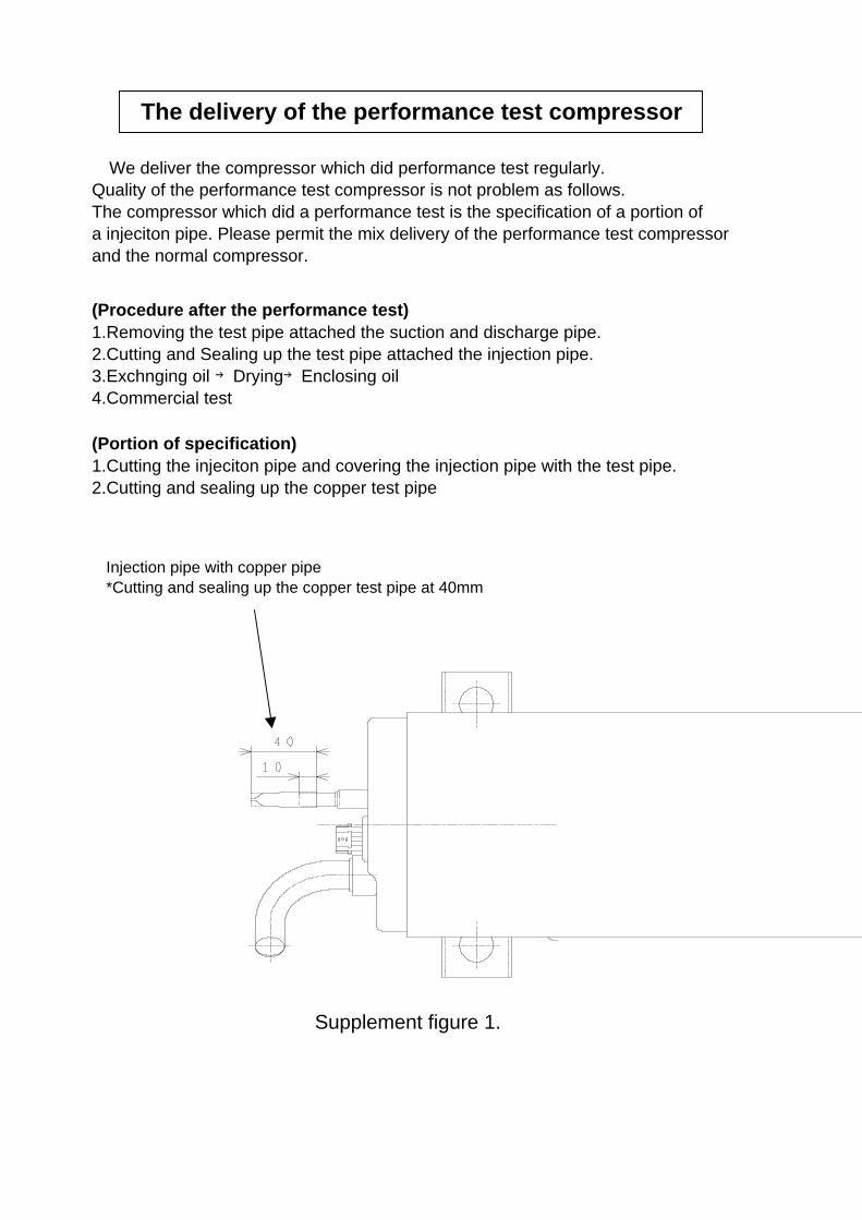
The delivery of the performance test compressor
We deliver the compressor which did performance test regularly.Quality of the performance test compressor is not problem as follows.The compressor which did a performance test is the specification of a portion ofa injeciton pipe. Please permit the mix delivery of the performance test compressorand the normal compressor.
(Procedure after the performance test)1.Removing the test pipe attached the suction and discharge pipe.2.Cutting and Sealing up the test pipe attached the injection pipe.3.Exchnging oil →Drying→Enclosing oil4.Commercial test
Injection pipe with copper pipe*Cutting and sealing up the copper test pipe at 40mm
(Portion of specification)1.Cutting the injeciton pipe and covering the injection pipe with the test pipe.2.Cutting and sealing up the copper test pipe
Supplement figure 1.