Technical Specifications for Single Phase Electronic Energy Meter of Class 1
42
TECHNICAL SPECIFICATION FOR A.C. Single Phase, 2 Wire Solid State (Static) Fully Electronic Energy Meter, Accuracy Class 1.0 & Current Rating 5-30 Amp. with Backlit LCD Display for 240 Volt System fitted with Pilfer Proof Meter Box.
Transcript of Technical Specifications for Single Phase Electronic Energy Meter of Class 1

TECHNICAL SPECIFICATION FOR
A.C. Single Phase, 2 Wire Solid State (Static) Fully Electronic Energy Meter, Accuracy Class 1.0 &
Current Rating 5-30 Amp. with Backlit LCD Display for 240 Volt System fitted with Pilfer Proof Meter Box.
WEST BENGAL STATE ELECTRICITY DISTRIBUTION COMPANY LIMITED
Technical Specifications for Single Phase Electronic Energy Meter of Class 1.0 Accuracy
1.0 SCOPE
a) This specification covers design, engineering, manufacture, testing, inspection & supply of A.C. Single phase, two wire solid state (static) fully electronic energy meters of accuracy class 1.0 & current rating 5-30 A, with backlit LCD display for 240 Volt systems as per requirement in this specification and pilfer proof meter box (PPMB) made of engineering plastic, FR grade with self extinguishing property suitable for single phase meter. The meter should be capable of recording & displaying energy in KWH & demand in KW for single phase two wire A.C. loads respectively for power factor range of Zero lag – unity – Zero lead. Meters should have facility/ capability of recording tamper information.
b) It is not the intent to specify completely herein all the details of the design and construction of meter. However the meter shall conform in all respects to high standards of engineering, design and workmanship shall be capable of performing commercial operation continuously in a manner acceptable to WBSEDCL, who will interpret the meanings of drawings & specification and shall have the right to reject any work or material which in its judgment is not in accordance therewith. The offered meter shall be complete with all components, accessories necessary for their effective and trouble free operation of the system for the purpose mentioned above. Such components shall be deemed to be within the scope of bidders supply irrespective of whether those are specifically brought out in this specification and / or the commercial order or not.
c) The original manufacturers of LT A.C. static energy meters shall only quote against this tender. In case of foreign manufacturers their authorized agent may also bid provided that they should be registered vendor and shall have all the testing facilities in India. They should also produce the documents authorizing them as agents, in India. It is mandatory that in case of all manufacturers, the offered meter shall be ISI marked and bidder shall have to furnish valid BIS certification along with the offer.
2.0 STANDARDS APPLICABLE
Unless specified elsewhere in this specification, the performance & testing of the meters should conform to the following Indian/International standards, to be read with up to date and latest amendments/revisions thereof as on 90 days prior to floating of tender.
Sl. No. Standard No. Title
1 IS 13779, 1999 read with its latest amendments
Specification of AC Static Watt hour meters class 1.0 & 2.0
2 CBIP Report No.304 read with latest amendments
Specification for AC Static Electrical Energy Meters
3 IS 12346 (1988) Specification for testing equipment for A.C. Static Electrical Energy Meter (latest amendment).
4 C.E.A. Regulation No. 502 / 70 / CEA / DP&D dt 17/03/2006
Central Electricity Authority (Installation & Operation of Meters) Regulation, 2006.
5 IS 14434 (1998) Polycarbonate Moulding & Extrusion Materials.
3.0 CLIMATIC CONDITION
The meters to be supplied against this specification should be suitable for satisfactory continuous operation under the following tropical conditions. Meters should be capable of maintaining required accuracy under hot, tropical and dusty climatic conditions.
i) Maximum Ambient Air Temperature in shade : 550 C
ii) Minimum Ambient Air Temperature : (-)100 C.
iii Maximum Relative Humidity : 95%(non-condensing) iv) Minimum Relative Humidity : 10% v) Height above mean sea level : Up to 3000 meters
vi) Average number of tropical monsoon per annum : 5 months
vii) Annual Rainfall : 100 mm to 1500 mm
4.0 SUPPLY SYSTEM
System 1 Phase 2 Wire
Rated voltage (Vref) 240 V – Phase to Neutral
Rated Current Basic current 5 Amps (lb), Maximum current 30 Amps (l max)
Rated Frequency 50 Hz
5.0 POWER FACTOR RANGE
The meter should be suitable for full power factor range from zero (lagging) through to Unity to zero (leading).
6.0 POWER SUPPLY VARIATION
The meter should be suitable for working with following supply system variations.
System 1 Phase 2 Wire
Specified range of operation 70% to 120% of reference Voltage i.e. 240 Volt.
Frequency 50Hz +5%
7.0 ACCURACY
7.1 Class of accuracy of the meter should be 1.0. The accuracy should not drift with time.
7.2 Maximum error limit at 1% Ib, UPF should preferably be within +/- 2%.
7.3 For voltage variation use of “between 70% to 50%” of Vref.allowable error limit is +/- 4%.
8.0 POWER CONSUMPTION
8.1 Voltage Circuit: The active and apparent power consumption in the voltage circuit including the power supply of meter at reference voltage, reference temperature and reference frequency should not exceed 1.0 Watt and 4 VA respectively.
8.2 Current Circuit: The apparent power taken by each current circuit at basic current, reference frequency and reference temperature should not exceed 1 VA.

9.0 STARTING CURRENT & RUNNING AT NO LOAD
The meter should start registering energy at 0.2 % of basic current at unity power factor and first pulse must be appeared within 10 minutes (i.e. time between two consecutive pulses). Running at no load: When 70% & 120% voltage is applied and no current flows in the current circuit, the test output of the meter should not produce more than one pulse.
10.0 MAXIMUM CONTINUOUS CURRENT
The maximum continuous current in meters should be the current at which the meter purports to meet the accuracy requirement of the specification. The same is indicated in table in clause 4 above.
11.0 GENERAL & CONSTRUCTIONAL REQUIREMENTS
11.1 Meters should be designed and constructed in such a way so as to avoid causing any danger during use and under normal conditions. However, the following should be ensured. a) Personal safety against electric shock b) Personal safety against effects of excessive temperature. c) Protection against spread of fire d) Protection against penetration of solid objects, dust & water
11.2 The meter should be designed with ASIC (application specific integrated circuit) and should be manufactured using SMT (Surface Mount Technology) components. Power supply and voltage divider circuits may be of PTH (Pin Through Hole) technology.
11.3 The meter should be housed in a safe, high grade, unbreakable, fire resistant, UV stabilized, virgin Polycarbonate casing of projection mounting type. The meter cover should be transparent, for easy reading of displayed parameters, and observation of operation indicators. The meter base may not be transparent, but it should not be black in colour. The meter casing should not change in shape, colour, size, and dimensions when subjected to 200 hrs on UV test as per ASTMD 53. It should withstand 650 deg. C. glow wire test and heat deflection test as per ISO 75. The meter cover should be sealable to the meter base with at least 2 nos. seals.
11.4 The meter should be supplied with a transparent extended terminal block cover (ETBC). The ETBC should not be easily detachable from the base and be secured to the base using a hinge/ without hinge arrangement. ETBC should be closed at the bottom to prevent access for wires to terminal holes, but should have a slot of size 20mm X 20 mm on extreme right hand side of the bottom of the terminal cover as per enclosed Drawing No.-(1). The terminal block should be made of high grade non-hygroscopic, fire retardant, fire resistant, glass reinforced poly-carbonate with terminal holes of minimum dia 5.5 mm and should be suitable to accommodate the insulation of the conductors, meeting the requirement of IS 13779 / CBIP technical report-304. The minimum center-to-center distance clearance between adjacent terminals should be 13 mm. Terminal cover should have provision for sealing with at least one seal.
The bidder shall submit relevant documents regarding the procurement of polycarbonate material. The polycarbonate material of only the following manufacturers shall be used : a) G.E. Plastics/SABIC LEXAN 943A or equivalent for cover & Terminal cover /
LEXAN 503R or equivalent for base.
b) BAYER Grade corresponding to above
c) DOW Chemicals - DO -
d) MITSUBISHI - DO -
e) TEJIN - DO -
f) DUPONT - DO -

11.5 All insulating material used in the construction of meters should be non-hygroscopic, non-ageing and of tested quality. All parts that are likely to develop corrosion should be effectively protected against corrosion during operating life by providing suitable protective coating.
11.6 The meter should conform to the degree of protection IP 51 for protection against ingress of dust, moisture and vermin.
11.7 The meter should be capable of providing phase to neutral protection up to 433 V for 4 hours.
11.8 The manner of fixing the cables to the terminal block should ensure adequate and durable contact such that there is no risk of loosening or undue heating. Meter should have 2 screws in each terminal for effective clamping of cables. The screws shall not have pointed ends at the end of the thread. Screw connections transmitting contact force and screw fixing which may be loosened and tightened several times during the life of the meter should be such that the risk of corrosion resulting from contact with any other metal part is minimized. Electrical connections should be so designed that contact pressure is not transmitted through insulating material. All terminals and connecting screws and washers should preferably be of tinned / nickel plated brass material. The terminals and all connecting screws will be of suitable material capable of withstanding a current of 150% of Imax for two hours, continuously.
11.9 The meter should be compact in design. The entire construction should be capable of withstanding stresses likely to occur in actual service and rough handling during transportation. The meter should be convenient to transport and immune to shock and vibration during transportation and handling.
11.10 The meter should have fixing holes, at least one at top and two at bottom. The top hole should be such that the holding screw is not accessible after fixing the meters. The lower fixing screws should be provided under the sealable terminal cover.
11.11 The meter should be fitted with SHUNT for measuring current in the phase element. The Neutral element may have either C.T. or SHUNT or HALL EFFECT SENSOR with proper isolation. The shunts, used in current circuit must be of high quality having high thermal stability and temperature co-efficient. The shunts should be E-Beam / Spot welded. In case of Hall Effect Sensor, meter should record as per requirement of technical specification in normal & tamper conditions and life of battery used for recording & recording & display during single wire operation as per clause 12 (IX) should be guaranteed for 10 years.
11.12 The meter cover should be permanently fixed to the meter base by using ultra sonic welding or any other technology which is either equally or more efficacious in such a way that the meter cover can‟t be opened without breaking the same, i.e. the meter should be break-to-open type. In case any attempt is made to separate the meter cover from the base by using any tools / implements / device, there should be visible evidence of tampering or attempt to open. The bidder will have to specify the type of technology used by him and will also indicate the tests / standard required for testing the same along with test certificates. However, sealing with commonly available adhesives will not be accepted.
11.13 Meter should have an indication in its display if top cover is removed even in power off condition and it should not disappear even if cover is fitted.
11.14 Sealing Arrangement: The sealing screws used for the meter cover shall be fixed upside down so that these are tightened from the rear or screw less design for fixing the base and cover but provision for sealing arrangement must be there. A run through screw (stud) has to be provided from bottom side & sealing is to be done on the top side of the meter. Two independent sealing screws are to be provided at each sides of the meter casing. The sealing screws shall be Tinned Brass or Nickel Plated Steel/Brass. In addition to the sealing screws provided to the meter cover, the sealing screws of the terminal cover should be Tinned Brass or Nickel platted steel. Meters must be supplied with 2 nos manufacture’s seal between meter base & cover at both sides.
12.0 ANTI-TAMPER FEATURES
The meter should have the following anti-tamper features and should record & register forward energy accurately under the following conditions :
i) Input phase and neutral connections are interchanged. Reverse power indication LED
should be provided or indication should be in display circuit.
ii) Incoming mains is connected to outgoing terminals and load is connected to incoming
terminals.
iii) A combination of conditions (i) and (ii) occurs.
iv) Load return is connected to a local earth and not returned to the meter as well as the
phase and neutral at supply side are reversed.
v) A combination of `(ii) and (iv)‟ or (iii)‟ and (iv)‟ occurs.
vi) A part of the load is returned to a local earth and the other part is returned to the meter.
“Earth load indication “should appear if difference of current between phase and neutral
lies between 6% to10% .
vii) Meter should record energy with maximum error of (+) 6% to (-) 4% on Injection of DC
(+) ve & DC (-) ve in neutral having magnitude up to 400 V & injection of chopped AC in
neutral. Tests in this respect will be conducted by using a device available with us for
chopped AC injection (60V to 300V) & steady DC injection. DC voltage will be rectified
from a three phase power supply. Single phase Circuit diagram of the device enclosed
with the tender documents.
viii) Meter should record energy with maximum error of +/- 4% even in absence of neutral
wire not connected at incoming & outgoing, i.e. single wire operation. In such condition
Meter should start recording energy at 1.0 Amps. However, meters, which are immune
or maintain better accuracy, will be preferred. Both elements should record energy
under single wire mode if same phase is given in both elements and load is driven
through earth.
ix) The meter should be immune to Electro Static Discharge or sparks of 35 KVp. Approx
generated from automobile ignition coil. Tests in this respect will be conducted by using
commonly available devices and during spark discharge test, spark will be applied
directly at all vulnerable points of the meter for a period of 10 to 20 minutes and meter
should record under this condition. After application of spark discharge meter should
record correctly within the specified limits of errors. Beyond 35 KVp meter should record
as tamper if not immune.
Meters should offer compliance to requirements of CBIP-304 and its amendments for tampering using external magnets. The meter should be immune to tamper using external magnets. The meters should be immune to 0.2T of A.C. magnetic fields and 0.27 T of D.C. magnetic fields, beyond which it should record as tamper if not immune. Meter should record Imax with the application of 0.5T permanent magnet with logging in BCS, if not immune The meter should offer a link less design i.e. there is no isolation link provided between the current and voltage circuits and hence there would not be any possibility of tampering with the same. The meter should be capable of recording the following tamper events in memory (minimum 25 events) with date

and time stamp preferably along with snapshots of V, I, PF and Kwh. The logging will be on FIFO basis. - Current reversal - Neutral Disturbance - Magnetic Tamper
13.0 DISPLAY
13.1 The measured value(s) should be displayed on a Liquid Crystal display (LCD) register. The height X width of the digit should be minimum 8.0 X 5 mm. The KWh energy registration should take place with 6 complete digits. The display should have backlit capability for easy reading. When the LCD is placed at a constant temperature of 65 deg C for a period of 30 minutes in operating condition and 80 deg C for 30 mins. Under de-energized / storage condition, it should not get deformed. The LCD should be of TN (Twisted Pneumatic) type with display size area of at least 40 X 15 mm. The display should have wide viewing angle of at least 70 deg. Dot Matrix type LCD will not be acceptable. Display should have viewing angle 35 degree up & down from eye level.
13.2 The data should be stored in non-volatile memory (NVM). The non-volatile memory should retain data for a period of not less than 10 years under un-powered condition. Battery back-up memory will not be considered as NVM.
13.3 The register should be able to record and display starting from zero, for a minimum of 2500 hours, the energy corresponding to rated maximum current at reference voltage and unity power factor. The register should not roll over in between this duration.
13.4 In addition to provide serial number of the meter on the display plate, the meter serial number should also be programmed into meter memory for identification through communication port for CMRI / Laptop / meter reading print out.
13.5 It should be possible to read the meter during power –off condition. It should also be possible to read the meter with CMRI / Laptop in this condition. If battery is used for the same, it should be a separate battery and not the one used for RTC. The battery should be of high quality Lithium / Lithium – ion battery, with life of at least 10 years. In case of Lithium battery no of operations per day are to be restricted to maximum 5(five) operations so that battery life is not hampered during ten years.
14.0 DISPLAY SEQUENCE
The meter should display the required parameters in two different modes as per the sequence given below.
A) Auto Display Mode :
The following parameters hereinafter referred to as “Billing Parameters” (B.P) should be displayed in an auto-cycle mode, in the following sequence :
B) 1. LCD Test 2. Real Time 3. Date 4. Cumulative Active energy (forwarded) reading (kWh) 5. Last Bill Maximum demand (kW) 6. Billing period counts Each parameter should be on meter display for 10 seconds and the time gap between two auto-cycles should be 120 seconds
Push Button Mode :
In addition to the auto display mode parameters, the following parameters should be displayed on pressing the push button (All displays of auto mode and the following)
1. Last Bill Active Forward energy
2. Instantaneous Load (KW)
3. Instantaneous voltage, current(whichever is higher between Ip &In)

4. Maximum demand kW for Current month
5. Supply Frequency
6. TOD Energy
7. Instantaneous Power Factor
8. Tamper Count
9. Meter serial no The meter should also be capable of offering a high resolution display which should enable conducting
of dial testing by the user in the shortest possible time and as a minimum, the meter should be capable of offering a resolution of 4 digits after decimal & 2 digits before decimal for the high resolution KWh display or 2 digits after decimal & 4 digits before decimal for the high resolution Wh display. Any other useful display will be acceptable. Accuracy test for low load will be measured by short dial test as well as pulse count test.
15.0 MAXIMUM DEMAND REGISTRATION & RESET
Meter should continuously monitor & calculate the average maximum demand for each demand interval time of 30 minutes and maximum of these in a calendar month should be stored along with date and time when it occurred. The maximum demand should automatically reset at 24:00 hrs. of the last date of each calendar month and the corresponding value along with date/time stamp shall be transferred to Billing(History) registers.
The integration period should be set as 30 minutes, on real-time basis.
The billing purpose parameters (active forwarded energy, maximum demand in kW) should be recorded and should be available in Bill (History) for a minimum period of last 12 months.
16.0 TIME OF USE / Time of Day MONITORING
The meter should offer the capability of time of use monitoring for energy. Minimum 2 registers should be capable of being configured for TOD monitoring for Peak / off peak hours. Time slots T1-23-00 Hrs. to 17-00 Hrs. of next day and T2-17-00 Hrs. to 23-00 Hrs. In case of any change of Time slots in future as per directive of SERC, the same is to be incorporated by the supplier even after completion of the order as per instruction from the appropriate authority.
17.0 SELF- DIAGNOSTIC FEATURE
The meter should be capable of performing complete self diagnostic check to monitor integrity of data memory location at all time. The meter should have indication for unsatisfactory / nonfunctioning / malfunctioning of the following :
a) Time and date on meter display b) All display segments on meter display c) Real Time Clock (RTC) status in meter reading prints out at BCS end d) Non-volatile Memory (NVM) status in meter reading prints out at BCS end
18.0 COMMUNICATION PORTS AND PROTOCOL:
The meter should have a galvanically isolated optical communication port for data communication with CMRI / Laptop. The port should be compatible with IEC 1107/PACT/ANSI. Adequate sealing provision should be provided.
19.0 CMRI / Laptop / BCS REQUIREMENTS The Common Meter Reading Instrument (CMRI / Laptop) should be capable of being loaded with user-friendly software (MS-DOS 5.0 or higher version compatible) for reading / downloading meter data. Windows based Base Computer Software (BCS) should be provided for receiving data from CMRI / Laptop and downloading instructions from base computer software to CMRI / Laptop.. The BCS should be WIN Xp, WIN vista, WIN 7 pro based and copy righted. The data stored in the meters memory should be available on the BCS.

This BCS should have, amongst other requirements, features and facilities described later in this specification, the facility to convert meter reading data into user definable ASCII file format so that it may be possible for the user to integrate the same with the user‟s billing data and process the selected data in desired manner. All the data available in the meter including energy, MD, and history data should be convertible to user defined ASCII file format for integration with third party software. The vendor should supply necessary base computer software for reading / viewing of meter data and converting to user defined ASCII files formats. The user should have the flexibility to select the parameters to be converted into ASCII file. The vendor should also supply the necessary CMRI / Laptop software. The bidder has to supply the Meter Reading protocol (API) free of cost. The protocol should not be complicated & should be easily understandable to introduce compatibility between meters, BCS and CMRI of other makes. The bidder shall indicate the relevant standard to which the protocol complies.
The compatibility of transferring data from the meter to CMRI & then to the BCS should be easily
established. Any change or up gradation of CMRI software or BCS in future, required for any reason, has to be done by the supplier at his own cost. It should not be possible to alter date in the meter by-passing commands from the CMRI or Laptop. For alteration of RTC time, change of TOD timing, Billing parameters(KWH,KVAH, MD in KW& KVA, TOD wise KWH,Average P.F, Average L.F) .It should be possible to perform these functions through CMRI but only through authenticated commands sets by BCS after scheduling for particular meter Sl.nos. No alternation, change should be possible through authenticated commands sets by BCS without scheduling of meters. Moreover, no alternation, change should be possible using CMRI only, i.e. the control has to be with the BCS. 100 nos. Meter to CMRI communication cord should be supplied to the office of the C.E. (DTD) for distributions at sites.
20.0 DISPLAY POWER UP IN ABSENCE OF MAINS SUPPLY The meter should have the provision of providing the display of billing parameters in absence of main supply. Press of push button should activate the display to facilitate hands free meter reading with auto-off provision. It should be possible to read the meter using CMRI during power-off condition using this facility.
21.0 MARKING OF THE METER
The marking on the meter should be in accordance with relevant clauses of IS 13779. The basic marking on the meter nameplate should be as follows (all other markings as per IS should also be there) :
a) Manufacturer‟s name & trade mark b) Type Designation c) No. of phases & wires d) Serial number (Size not less than 5mm) e) Month & Year of manufacture f) Reference Voltage g) Rated Current h) Operating Frequency i) Principal unit(s) of measurement j) Meter Constant (imp/kwh) k) Class index of meter l) “Property of WBSEDCL” m) Purchase Order No. & Date n) Guarantee (Guaranteed for a period of 5
1/2 Yrs. from the date of delivery)
o) BIS marking p) Place of manufacture
q) Bar coded Sl no. of the meter along with manufacturing date.
22.0 CONNECTION DIAGRAM & TERMINAL MARKINGS:
The connection diagram of the meter should be clearly shown on terminal cover.
23.0 OUTPUT DEVICE
The meter should have a test output accessible from the front and capable of being monitored with suitable testing equipment while in operation at site. The test output device should be provided in the form of LED output. There should be adequate clearance of the test output from other outputs so that there is no interference of other outputs while performing accuracy test with standard scanners. The relation between test output and the indication on display should comply with the marking on the name plate (imp per KWh)
24.0 ELECTRO-MAGNETIC-COMPATIBILITY & INTERFERENCE REQUIREMENT
The meter should meet EMI / EMC requirements as specified in the relevant standards described in Clause 2.0 of this specification.
25.0 PROCUREMENT OF SEALS :
The manufacturer of meter will be responsible for sealing of the meters at his works with his own two (2) nos. Polycarbonate seals with manufacturers logo & sequential numbers.
A Tracking & recording software (25 nos. or more as per our requirement) for all new seals shall be provided by the manufacturer of the meter so as to track total movements of the seals starting from manufacturing, procurement, storage, record keeping, installation, series of inspections, removal & disposal. Seal tracking software should be submitted and installed at PC/Laptop of the purchaser before commencement of supply of meters.

General Requirements
1. GUARANTEED TECHNICAL PARTICULARS :
The bidder shall furnish all the necessary information as desired in the Schedule of Guaranteed
Technical Particulars and data, appended with this Specification. If the bidder desire to furnish any other information(s) in addition to the details as asked for, the same may be furnished against the last item of this Annexure–I
2. TECHNICAL DEVIATIONS :
Any deviation in Technical Specification as specified in the Specification shall be specifically and clearly indicated in the Schedule of deviation format.
3. TESTS :
i) Type Testing of Meter :
The offered meters should be type tested at any NABL accredited laboratory in accordance with IS 13779 with latest amendments, CBIP Report 304 with latest amendments. The type test report should not be more than 3 (three) years old. A copy of the Type Test results should be enclosed with the offer. If there is any modification in the design/parameters of the specifications or use of constituent materials in the offered meters submitted with the offer, from the meter which was submitted type tested, which may affect the characteristics as well as parameters of the meter, revised type test certificates as per the design, parameters and constituent material used in the offered meter, shall have to be submitted failing which the offer may be liable to be rejected.
Type Test Certificate from any NABL accredited Lab. shall only be considered.
Type test certificate should contain the following information clearly :
1) Class of accuracy. 2) Meter constant
ii) Acceptance tests :
The acceptance tests as stipulated in CBIP / IS (with latest amendments) and shall be carried out by the
supplier in presence of purchaser‟s representative. Lot size, sampling and procedure to be followed for acceptance test will be as stated below
The lot size of Meters is 10,000 nos. & no. of Sample Meters to be selected at random from the lot is 32 nos.
The following tests shall be carried out on all the 32 nos. meters thus selected at random.
The WBSEDCL‟s Engineers shall witness the various quality control measures adopted for verification of different components of meters and satisfy themselves about the same. They shall also inspect the protocol for maintaining the accuracy of the meter testing equipment with reference to the standard at manufacturer‟s meters testing station.
Physical examination of the meters.
Non-registration with Voltage along at 70% V ref and at 120% V ref.
Starting current at 0.2% I basic Upf
High voltage test.
Insulation resistance test.
Test of protection for withstanding 433 volt between phase & neutral for a period of at least 4 hours without any load.
Test of endurance up to 150% I max
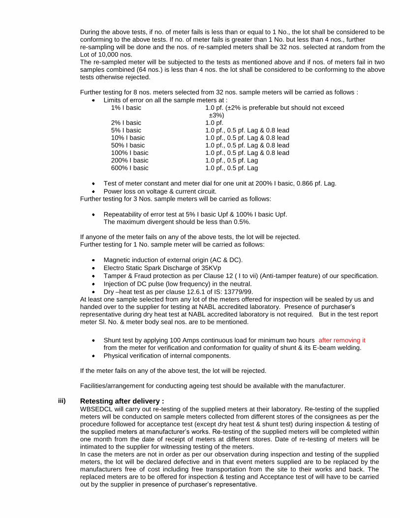
During the above tests, if no. of meter fails is less than or equal to 1 No., the lot shall be considered to be conforming to the above tests. If no. of meter fails is greater than 1 No. but less than 4 nos., further re-sampling will be done and the nos. of re-sampled meters shall be 32 nos. selected at random from the Lot of 10,000 nos. The re-sampled meter will be subjected to the tests as mentioned above and if nos. of meters fail in two samples combined (64 nos.) is less than 4 nos. the lot shall be considered to be conforming to the above tests otherwise rejected.
Further testing for 8 nos. meters selected from 32 nos. sample meters will be carried as follows :
Limits of error on all the sample meters at :
1% I basic 1.0 pf. (±2% is preferable but should not exceed ±3%)
2% I basic 1.0 pf. 5% I basic 1.0 pf., 0.5 pf. Lag & 0.8 lead 10% I basic 1.0 pf., 0.5 pf. Lag & 0.8 lead 50% I basic 1.0 pf., 0.5 pf. Lag & 0.8 lead 100% I basic 1.0 pf., 0.5 pf. Lag & 0.8 lead 200% I basic 1.0 pf., 0.5 pf. Lag 600% I basic 1.0 pf., 0.5 pf. Lag
Test of meter constant and meter dial for one unit at 200% I basic, 0.866 pf. Lag.
Power loss on voltage & current circuit. Further testing for 3 Nos. sample meters will be carried as follows:
Repeatability of error test at 5% I basic Upf & 100% I basic Upf. The maximum divergent should be less than 0.5%. If anyone of the meter fails on any of the above tests, the lot will be rejected.
Further testing for 1 No. sample meter will be carried as follows:
Magnetic induction of external origin (AC & DC).
Electro Static Spark Discharge of 35KVp
Tamper & Fraud protection as per Clause 12 ( I to vii) (Anti-tamper feature) of our specification.
Injection of DC pulse (low frequency) in the neutral.
Dry –heat test as per clause 12.6.1 of IS: 13779/99. At least one sample selected from any lot of the meters offered for inspection will be sealed by us and handed over to the supplier for testing at NABL accredited laboratory. Presence of purchaser‟s representative during dry heat test at NABL accredited laboratory is not required. But in the test report meter Sl. No. & meter body seal nos. are to be mentioned.
Shunt test by applying 100 Amps continuous load for minimum two hours after removing it
from the meter for verification and conformation for quality of shunt & its E-beam welding.
Physical verification of internal components. If the meter fails on any of the above test, the lot will be rejected. Facilities/arrangement for conducting ageing test should be available with the manufacturer.
iii) Retesting after delivery : WBSEDCL will carry out re-testing of the supplied meters at their laboratory. Re-testing of the supplied meters will be conducted on sample meters collected from different stores of the consignees as per the procedure followed for acceptance test (except dry heat test & shunt test) during inspection & testing of the supplied meters at manufacturer‟s works. Re-testing of the supplied meters will be completed within one month from the date of receipt of meters at different stores. Date of re-testing of meters will be intimated to the supplier for witnessing testing of the meters. In case the meters are not in order as per our observation during inspection and testing of the supplied meters, the lot will be declared defective and in that event meters supplied are to be replaced by the manufacturers free of cost including free transportation from the site to their works and back. The replaced meters are to be offered for inspection & testing and Acceptance test of will have to be carried out by the supplier in presence of purchaser‟s representative.
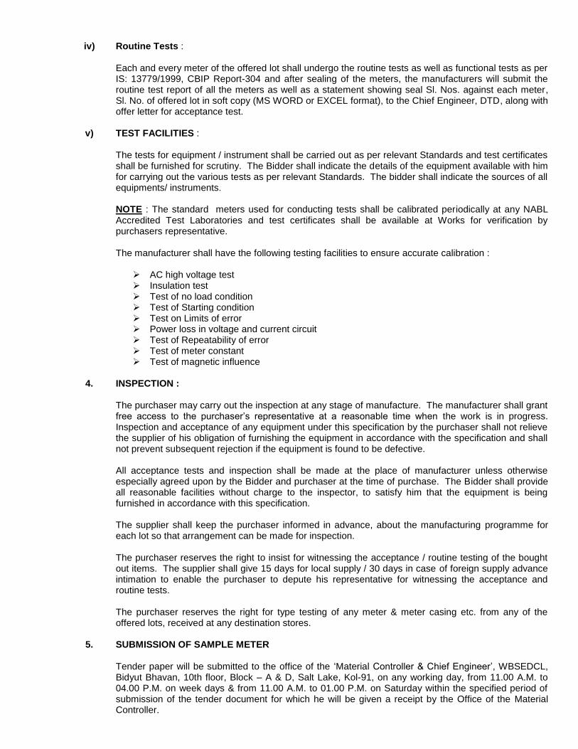
iv) Routine Tests :
Each and every meter of the offered lot shall undergo the routine tests as well as functional tests as per IS: 13779/1999, CBIP Report-304 and after sealing of the meters, the manufacturers will submit the routine test report of all the meters as well as a statement showing seal Sl. Nos. against each meter, Sl. No. of offered lot in soft copy (MS WORD or EXCEL format), to the Chief Engineer, DTD, along with offer letter for acceptance test.
v) TEST FACILITIES :
The tests for equipment / instrument shall be carried out as per relevant Standards and test certificates shall be furnished for scrutiny. The Bidder shall indicate the details of the equipment available with him for carrying out the various tests as per relevant Standards. The bidder shall indicate the sources of all equipments/ instruments.
NOTE : The standard meters used for conducting tests shall be calibrated periodically at any NABL Accredited Test Laboratories and test certificates shall be available at Works for verification by purchasers representative.
The manufacturer shall have the following testing facilities to ensure accurate calibration :
AC high voltage test Insulation test Test of no load condition Test of Starting condition Test on Limits of error
Power loss in voltage and current circuit Test of Repeatability of error Test of meter constant Test of magnetic influence
4. INSPECTION :
The purchaser may carry out the inspection at any stage of manufacture. The manufacturer shall grant
free access to the purchaser‟s representative at a reasonable time when the work is in progress. Inspection and acceptance of any equipment under this specification by the purchaser shall not relieve the supplier of his obligation of furnishing the equipment in accordance with the specification and shall not prevent subsequent rejection if the equipment is found to be defective.
All acceptance tests and inspection shall be made at the place of manufacturer unless otherwise
especially agreed upon by the Bidder and purchaser at the time of purchase. The Bidder shall provide all reasonable facilities without charge to the inspector, to satisfy him that the equipment is being furnished in accordance with this specification. The supplier shall keep the purchaser informed in advance, about the manufacturing programme for each lot so that arrangement can be made for inspection. The purchaser reserves the right to insist for witnessing the acceptance / routine testing of the bought out items. The supplier shall give 15 days for local supply / 30 days in case of foreign supply advance intimation to enable the purchaser to depute his representative for witnessing the acceptance and routine tests. The purchaser reserves the right for type testing of any meter & meter casing etc. from any of the offered lots, received at any destination stores.
5. SUBMISSION OF SAMPLE METER
Tender paper will be submitted to the office of the „Material Controller & Chief Engineer‟, WBSEDCL, Bidyut Bhavan, 10th floor, Block – A & D, Salt Lake, Kol-91, on any working day, from 11.00 A.M. to 04.00 P.M. on week days & from 11.00 A.M. to 01.00 P.M. on Saturday within the specified period of submission of the tender document for which he will be given a receipt by the Office of the Material Controller.
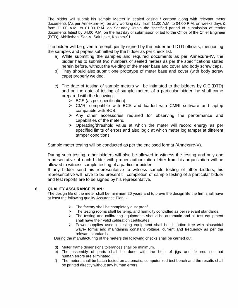
The bidder will submit his sample Meters in sealed casing / cartoon along with relevant meter documents (As per Annexure-IV), on any working day, from 11.00 A.M. to 04.00 P.M. on weeks days & from 11.00 A.M. to 01.00 P.M. on Saturday within the specified period of submission of tender documents latest by 04.00 P.M. on the last day of submission of bid to the Office of the Chief Engineer (DTD), Abhikshan, Sec-V, Salt Lake, Kolkata-91.
The bidder will be given a receipt, jointly signed by the bidder and DTD officials, mentioning the samples and papers submitted by the bidder as per check list.
a) While submitting the samples and required documents as per Annexure-IV, the bidder has to submit two numbers of sealed meters as per the specifications stated herein before, without the welding of the meter base and cover and body screw caps.
b) They should also submit one prototype of meter base and cover (with body screw caps) properly welded.
c) The date of testing of sample meters will be intimated to the bidders by C.E.(DTD)
and on the date of testing of sample meters of a particular bidder, he shall come prepared with the following : BCS (as per specification) CMRI compatible with BCS and loaded with CMRI software and laptop
compatible with BCS.
Any other accessories required for observing the performance and capabilities of the meters.
Operating/threshold value at which the meter will record energy as per specified limits of errors and also logic at which meter log tamper at different tamper conditions.
Sample meter testing will be conducted as per the enclosed format (Annexure-V). During such testing, other bidders will also be allowed to witness the testing and only one representative of each bidder with proper authorization letter from his organization will be allowed to witness sample testing of a particular bidder. If any bidder send his representative to witness sample testing of other bidders, his representative will have to be present till completion of sample testing of a particular bidder and test reports are to be signed by his representative.
6. QUALITY ASSURANCE PLAN : The design life of the meter shall be minimum 20 years and to prove the design life the firm shall have at least the following quality Assurance Plan: -
The factory shall be completely dust proof. The testing rooms shall be temp. and humidity controlled as per relevant standards. The testing and calibrating equipments should be automatic and all test equipment
shall have their valid calibration certificates. Power supplies used in testing equipment shall be distortion free with sinusoidal
wave- forms and maintaining constant voltage, current and frequency as per the relevant standards.
During the manufacturing of the meters the following checks shall be carried out.
d) Meter frame dimensions tolerances shall be minimum. e) The assembly of parts shall be done with the help of jigs and fixtures so that
human errors are eliminated. f) The meters shall be batch tested on automatic, computerized test bench and the results shall
be printed directly without any human errors.
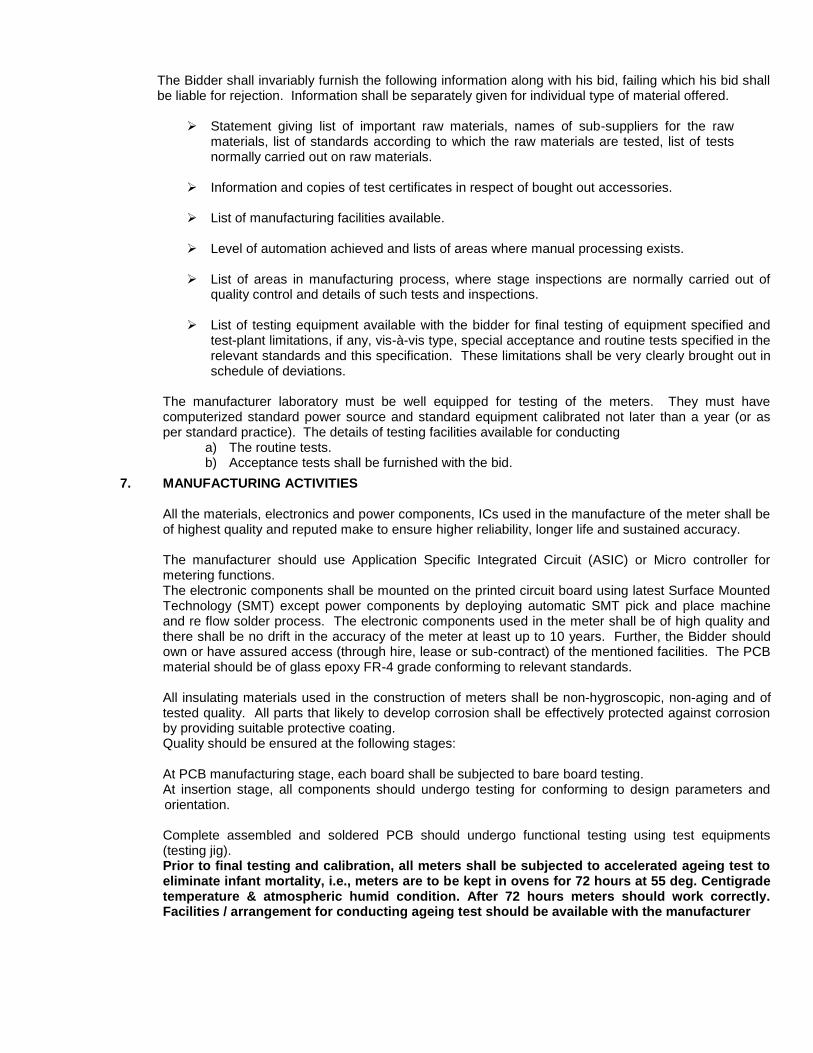
The Bidder shall invariably furnish the following information along with his bid, failing which his bid shall be liable for rejection. Information shall be separately given for individual type of material offered. Statement giving list of important raw materials, names of sub-suppliers for the raw
materials, list of standards according to which the raw materials are tested, list of tests normally carried out on raw materials.
Information and copies of test certificates in respect of bought out accessories.
List of manufacturing facilities available.
Level of automation achieved and lists of areas where manual processing exists.
List of areas in manufacturing process, where stage inspections are normally carried out of
quality control and details of such tests and inspections. List of testing equipment available with the bidder for final testing of equipment specified and
test-plant limitations, if any, vis-à-vis type, special acceptance and routine tests specified in the relevant standards and this specification. These limitations shall be very clearly brought out in schedule of deviations.
The manufacturer laboratory must be well equipped for testing of the meters. They must have computerized standard power source and standard equipment calibrated not later than a year (or as per standard practice). The details of testing facilities available for conducting
a) The routine tests. b) Acceptance tests shall be furnished with the bid.
7. MANUFACTURING ACTIVITIES
All the materials, electronics and power components, ICs used in the manufacture of the meter shall be of highest quality and reputed make to ensure higher reliability, longer life and sustained accuracy. The manufacturer should use Application Specific Integrated Circuit (ASIC) or Micro controller for metering functions. The electronic components shall be mounted on the printed circuit board using latest Surface Mounted Technology (SMT) except power components by deploying automatic SMT pick and place machine and re flow solder process. The electronic components used in the meter shall be of high quality and there shall be no drift in the accuracy of the meter at least up to 10 years. Further, the Bidder should own or have assured access (through hire, lease or sub-contract) of the mentioned facilities. The PCB material should be of glass epoxy FR-4 grade conforming to relevant standards.
All insulating materials used in the construction of meters shall be non-hygroscopic, non-aging and of tested quality. All parts that likely to develop corrosion shall be effectively protected against corrosion by providing suitable protective coating. Quality should be ensured at the following stages:
At PCB manufacturing stage, each board shall be subjected to bare board testing. At insertion stage, all components should undergo testing for conforming to design parameters and orientation. Complete assembled and soldered PCB should undergo functional testing using test equipments (testing jig). Prior to final testing and calibration, all meters shall be subjected to accelerated ageing test to eliminate infant mortality, i.e., meters are to be kept in ovens for 72 hours at 55 deg. Centigrade temperature & atmospheric humid condition. After 72 hours meters should work correctly. Facilities / arrangement for conducting ageing test should be available with the manufacturer

The calibration of meters shall be done in-house. The bidder should submit the list of components used in the meter along with the offer. A detailed list of bought-out items, which are used in the manufacture of the meter, should be furnished indicating the name of firms from whom these items are procured. The bidder shall also give the details of quality assurance procedures followed by him in respect of the bought-out items. The details of testing facilities available for conducting the routine and acceptance tests and other special tests on the meter shall be furnished with the bid. The facility available if any for conducting type test may also be furnished.
8. DOCUMENTATION :
Each meter should have operating manuals inside each of the P.P.BOXES and 100 nos of additional quantity at DTD store. One set of routine test certificates shall accompany each dispatch consignment. The acceptance test certificates in case pre-dispatch inspection or a routine test certificate in cases where inspection is waived has to be approved by the purchaser.
9. GUARANTEE:
The meters should be guaranteed against any manufacturing defects arising out of faulty design or bad workmanship or component failure for a period of 5 ½ years from the date of supply.
Life of battery used for the meter should be guaranteed for 10 years.
The meter/battery found defective within the above guarantee period shall be replaced by the supplier free of cost within 60 days of the receipt of intimation of failure / defect.
REPLACEMENT OF DEFECTIVE METERS : The meters declared defective by the WBSEDCL shall be replaced by the supplier up to the full satisfaction of the WBSEDCL at the cost of supplier. Failure to do so within the time limit prescribe shall lead to imposition of penalty of twice the cost of meter. The same may lead to black listing even, as decided by WBSEDCL. In this connection the decision of WBSEDCL shall be final.
10. PACKING & FORWARDING : The equipment shall be packed in cartons / crates suitable for vertical / horizontal transport as the case may be, and suitable to withstand handling during transport and outdoor storage during transit. The supplier shall be responsible for any damage to the equipment during transit, due to improper and inadequate packing.
The easily damageable material shall be carefully packed and marked with the appropriate caution symbol. Wherever necessary, proper arrangement for lifting, such as lifting hooks etc., shall be provided. Supplier without any extra cost shall supply any material found short inside the packing cases immediately. The packing shall be done as per the standard practice as mentioned in IS 15707 : 2006. Each package shall clearly indicate the marking details (for e.g., manufacturer‟s name, Sl. Nos. of meters in the package, quantity of meter, and other details as per supply order). However, he should ensure the packing is such that, the material should not get damaged during transit by Rail / Road.
11. GENERAL :
a) Principle of operation of the meter, outlining the methods and stages of computation of various parameters starting from input voltage and current signals including the sampling rate, if applicable shall be furnished by the bidder. b) The Components used for manufacture of meter should be of high quality and the bidders should confirm component specification as specified below in Annexure-III. c) Bidders should compulsorily fill Annexure-I, Annexure-II & Annexure-III for technical qualification.
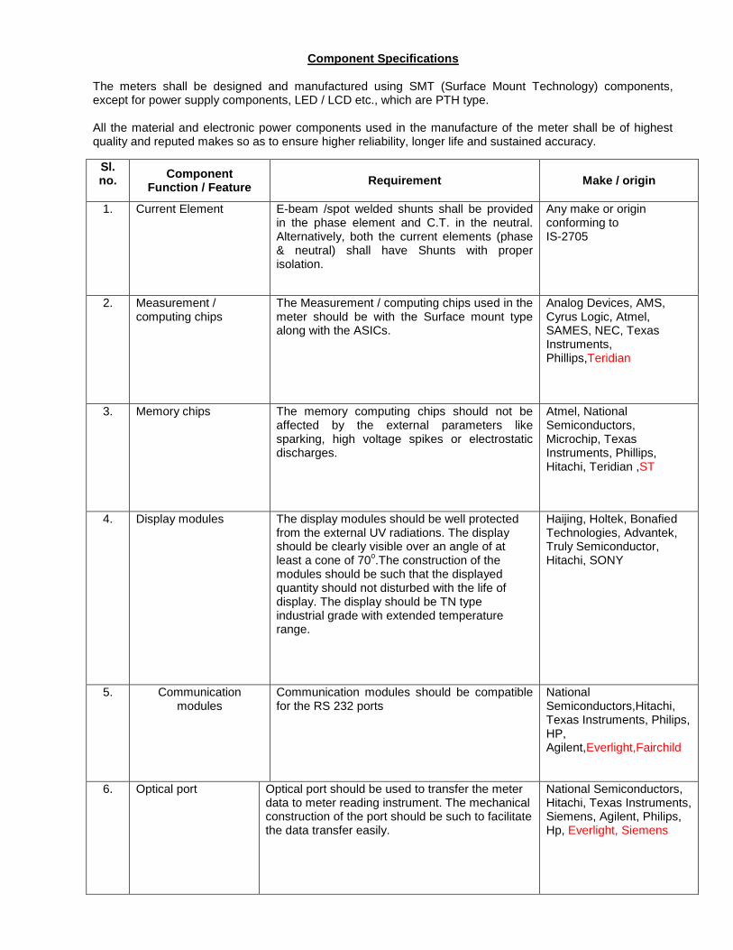
Component Specifications
The meters shall be designed and manufactured using SMT (Surface Mount Technology) components, except for power supply components, LED / LCD etc., which are PTH type. All the material and electronic power components used in the manufacture of the meter shall be of highest quality and reputed makes so as to ensure higher reliability, longer life and sustained accuracy.
Sl. no.
Component Function / Feature
Requirement Make / origin
1. Current Element E-beam /spot welded shunts shall be provided in the phase element and C.T. in the neutral. Alternatively, both the current elements (phase & neutral) shall have Shunts with proper isolation.
Any make or origin conforming to IS-2705
2. Measurement / computing chips
The Measurement / computing chips used in the meter should be with the Surface mount type along with the ASICs.
Analog Devices, AMS, Cyrus Logic, Atmel, SAMES, NEC, Texas Instruments, Phillips,Teridian
3. Memory chips
The memory computing chips should not be affected by the external parameters like sparking, high voltage spikes or electrostatic discharges.
Atmel, National Semiconductors, Microchip, Texas Instruments, Phillips, Hitachi, Teridian ,ST
4. Display modules The display modules should be well protected from the external UV radiations. The display should be clearly visible over an angle of at least a cone of 70
o.The construction of the
modules should be such that the displayed quantity should not disturbed with the life of display. The display should be TN type industrial grade with extended temperature range.
Haijing, Holtek, Bonafied Technologies, Advantek, Truly Semiconductor, Hitachi, SONY
5. Communication modules
Communication modules should be compatible for the RS 232 ports
National Semiconductors,Hitachi, Texas Instruments, Philips, HP, Agilent,Everlight,Fairchild
6. Optical port
Optical port should be used to transfer the meter data to meter reading instrument. The mechanical construction of the port should be such to facilitate the data transfer easily.
National Semiconductors, Hitachi, Texas Instruments, Siemens, Agilent, Philips, Hp, Everlight, Siemens

7. Power Supply
The power supply should be with the capabilities as per the relevant standards. The power supply unit of the meter should not be affected in case the maximum voltage of the system appears to the terminals due to faults or due to wrong connections.
As specified.
8. Electronic components
The active & passive components should be of the surface mount type & are to be handled & soldered by the state of art assembly processes.
Philips, Toshiba, Fairchild, Murata, Rohm, Siemens. National Semiconductors, ATMEL, Texas Instruments, Hitachi. Ligitec, OKI, EPCOS
9. Mechanical parts
The internal electrical components should be of electrolytic copper & should be protected from corrosion, rust etc. The other mechanical components should be protected from rust, corrosion etc. by suitable plating / painting methods.
10. Battery
Lithium / Lithium-ion /NiMh with guaranteed life of 10 years
Renata,Panasonic, Varta,Tedrium,Sanyo,National,Teridian Duracell,Maxell,Elegance
11. RTC / Micro controller
The accuracy of RTC shall be as per relevant IEC / IS standards
Philips, Dallas, Atmel, Motorola, NEC, Renesas, Hitachi, Xicor, Texas Instruments, NEC or OKI, ST,Mitsubishi
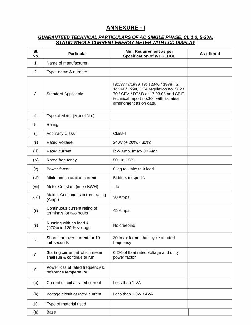
ANNEXURE - I
GUARANTEED TECHNICAL PARTICULARS OF AC SINGLE PHASE, CL 1.0, 5-30A, STATIC WHOLE CURRENT ENERGY METER WITH LCD DISPLAY
Sl. No.
Particular Min. Requirement as per
Specification of WBSEDCL As offered
1. Name of manufacturer
2. Type, name & number
3. Standard Applicable
IS:13779/1999, IS: 12346 / 1988, IS: 14434 / 1998, CEA regulation no. 502 / 70 / CEA / DT&D dt.17.03.06 and CBIP technical report no.304 with its latest amendment as on date..
4. Type of Meter (Model No.)
5. Rating
(i) Accuracy Class Class-I
(ii) Rated Voltage 240V (+ 20%, - 30%)
(iii) Rated current Ib-5 Amp. Imax- 30 Amp
(iv) Rated frequency 50 Hz ± 5%
(v) Power factor 0 lag to Unity to 0 lead
(vi) Minimum saturation current Bidders to specify
(vii) Meter Constant (imp / KWH) -do-
6. (i) Maxm. Continuous current rating (Amp.)
30 Amps.
(ii) Continuous current rating of terminals for two hours
45 Amps
(ii) Running with no load & (-)70% to 120 % voltage
No creeping
7. Short time over current for 10 milliseconds
30 Imax for one half cycle at rated frequency
8. Starting current at which meter shall run & continue to run
0.2% of Ib at rated voltage and unity power factor
9. Power loss at rated frequency & reference temperature
(a) Current circuit at rated current Less than 1 VA
(b) Voltage circuit at rated current Less than 1.0W / 4VA
10. Type of material used
(a) Base
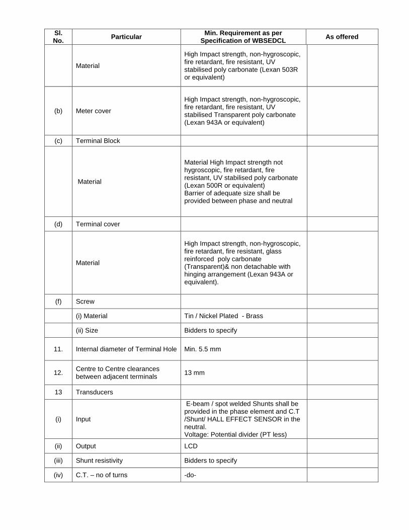
Sl. No.
Particular Min. Requirement as per
Specification of WBSEDCL As offered
Material
High Impact strength, non-hygroscopic, fire retardant, fire resistant, UV stabilised poly carbonate (Lexan 503R or equivalent)
(b) Meter cover
High Impact strength, non-hygroscopic, fire retardant, fire resistant, UV stabilised Transparent poly carbonate (Lexan 943A or equivalent)
(c) Terminal Block
Material
Material High Impact strength not hygroscopic, fire retardant, fire resistant, UV stabilised poly carbonate (Lexan 500R or equivalent) Barrier of adequate size shall be provided between phase and neutral
(d) Terminal cover
Material
High Impact strength, non-hygroscopic, fire retardant, fire resistant, glass reinforced poly carbonate (Transparent)& non detachable with hinging arrangement (Lexan 943A or equivalent).
(f) Screw
(i) Material Tin / Nickel Plated - Brass
(ii) Size Bidders to specify
11. Internal diameter of Terminal Hole Min. 5.5 mm
12. Centre to Centre clearances between adjacent terminals
13 mm
13 Transducers
(i) Input
E-beam / spot welded Shunts shall be provided in the phase element and C.T /Shunt/ HALL EFFECT SENSOR in the neutral. Voltage: Potential divider (PT less)
(ii) Output LCD
(iii) Shunt resistivity Bidders to specify
(iv) C.T. – no of turns -do-
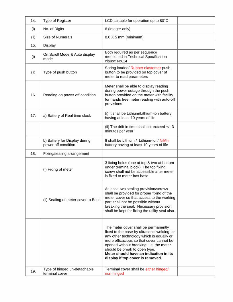
14. Type of Register LCD suitable for operation up to 80oC
(i) No. of Digits 6 (integer only)
(ii) Size of Numerals 8.0 X 5 mm (minimum)
15. Display
(i) On Scroll Mode & Auto display mode
Both required as per sequence mentioned in Technical Specification clause No.14
(ii) Type of push button Spring loaded/ Rubber elastomer push button to be provided on top cover of meter to read parameters
16. Reading on power off condition
Meter shall be able to display reading during power outage through the push button provided on the meter with facility for hands free meter reading with auto-off provisions.
17. a) Battery of Real time clock (i) It shall be Lithium/Lithium-ion battery having at least 10 years of life
(ii) The drift in time shall not exceed +/- 3 minutes per year
b) Battery for Display during power off condition
It shall be Lithium / Lithium-ion/ NiMh battery having at least 10 years of life
18. Fixing/sealing arrangement
(i) Fixing of meter
3 fixing holes (one at top & two at bottom under terminal block). The top fixing screw shall not be accessible after meter is fixed to meter box base.
(ii) Sealing of meter cover to Base
At least, two sealing provision/screws shall be provided for proper fixing of the meter cover so that access to the working part shall not be possible without breaking the seal. Necessary provision shall be kept for fixing the utility seal also.
The meter cover shall be permanently fixed to the base by ultrasonic welding or any other technology which is equally or more efficacious so that cover cannot be opened without breaking, i.e. the meter should be break to open type. Meter should have an indication in its display if top cover is removed.
19. Type of hinged un-detachable terminal cover
Terminal cover shall be either hinged/ non hinged

20. Performance of meter in tamper conditions
(i) Phase-neutral interchanged Should work within specified accuracy
(ii) Main & load wire are interchanged
----do----
(iii) Load is not terminated back to meter & current is drawn through local earth fully or partially
---do----
(iv) Neutral disconnected from both incoming & outgoing and load drawn through local earth
-do- provided threshold current is 1 Amp. & above
(v) Indication of above tamper condition
LCD / LED indication.
21.
Suitability of meter to sustain over voltage i.e. phase to phase voltage injected between phased & neutral
Should sustain
22 Electromagnetic compatibility (EMI / EMC severity level)
As per IS 13779: 1999
23.
(i) Effect on accuracy of external electromagnetic interference of electrical discharge, external magnetic field & DC current in AC supply or in neutral
Should work within accuracy as per latest IS & CBIP report -304 with latest amendment.
(ii) Immune to Electrostatic discharge upto 35kVp
Exceeding 35kVp it should log as tamper
(iii) Current reversal, Neutral disturbance & Magnetic tamper logging in memory
Meter shall log last 25 events with date and time
24. Effect on accuracy under tamper conditions / influence conditions
Should work within accuracy specified in IS: 13779 / 1999, and CBIP tech. Report 304 . Error beyond +/- 4 % will not be acceptable for conditions not specified in IS: 13779 / 1999 & CBIP tech. Report 304
25. Drift in accuracy of measurement with time
No Drift in accuracy in measurement with time
26. Name plate details It should cover all the details as prescribed in Clause-21
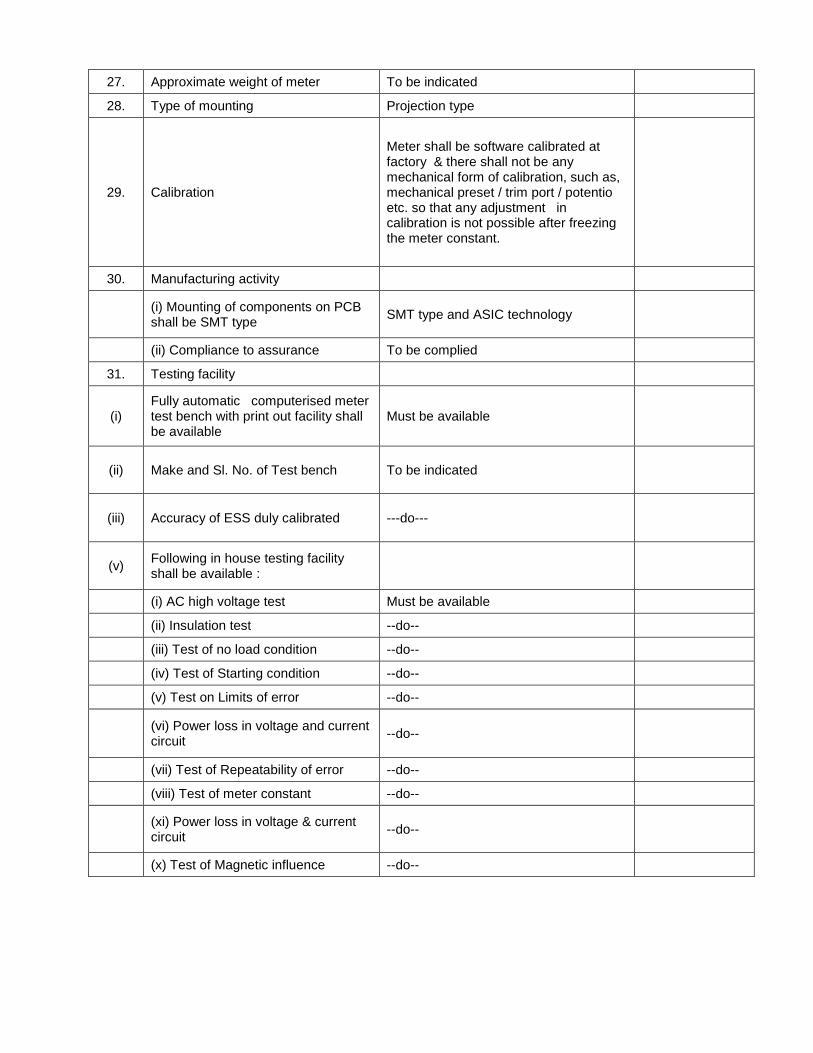
27. Approximate weight of meter To be indicated
28. Type of mounting Projection type
29. Calibration
Meter shall be software calibrated at factory & there shall not be any mechanical form of calibration, such as, mechanical preset / trim port / potentio etc. so that any adjustment in calibration is not possible after freezing the meter constant.
30. Manufacturing activity
(i) Mounting of components on PCB shall be SMT type
SMT type and ASIC technology
(ii) Compliance to assurance To be complied
31. Testing facility
(i) Fully automatic computerised meter test bench with print out facility shall be available
Must be available
(ii) Make and Sl. No. of Test bench To be indicated
(iii) Accuracy of ESS duly calibrated ---do---
(v) Following in house testing facility shall be available :
(i) AC high voltage test Must be available
(ii) Insulation test --do--
(iii) Test of no load condition --do--
(iv) Test of Starting condition --do--
(v) Test on Limits of error --do--
(vi) Power loss in voltage and current circuit
--do--
(vii) Test of Repeatability of error --do--
(viii) Test of meter constant --do--
(xi) Power loss in voltage & current circuit
--do--
(x) Test of Magnetic influence --do--
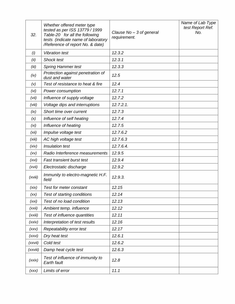
32.
Whether offered meter type tested as per ISS 13779 / 1999 Table-20 for all the following tests (indicate name of laboratory /Reference of report No. & date)
Clause No – 3 of general requirement.
Name of Lab Type test Report Ref.
No.
(i) Vibration test 12.3.2
(ii) Shock test 12.3.1
(iii) Spring Hammer test 12.3.3
(iv) Protection against penetration of dust and water
12.5
(v) Test of resistance to heat & fire 12.4
(vi) Power consumption 12.7.1
(vii) Influence of supply voltage 12.7.2
(viii) Voltage dips and interruptions 12.7.2.1.
(ix) Short time over current 12.7.3
(x) Influence of self heating 12.7.4
(xi) Influence of heating 12.7.5
(xii) Impulse voltage test 12.7.6.2
(xiii) AC high voltage test 12.7.6.3
(xiv) Insulation test 12.7.6.4.
(xv) Radio Interference measurements 12.9.5
(xvi) Fast transient burst test 12.9.4
(xvii) Electrostatic discharge 12.9.2
(xviii) Immunity to electro-magnetic H.F. field
12.9.3.
(xix) Test for meter constant 12.15
(xx) Test of starting conditions 12.14
(xxi) Test of no load condition 12.13
(xxii) Ambient temp. influence 12.12
(xxiii) Test of influence quantities 12.11
(xxiv) Interpretation of test results 12.16
(xxv) Repeatability error test 12.17
(xxvi) Dry heat test 12.6.1
(xxvii) Cold test 12.6.2
(xxviii) Damp heat cycle test 12.6.3
(xxix) Test of influence of immunity to Earth fault
12.8
(xxx) Limits of error 11.1
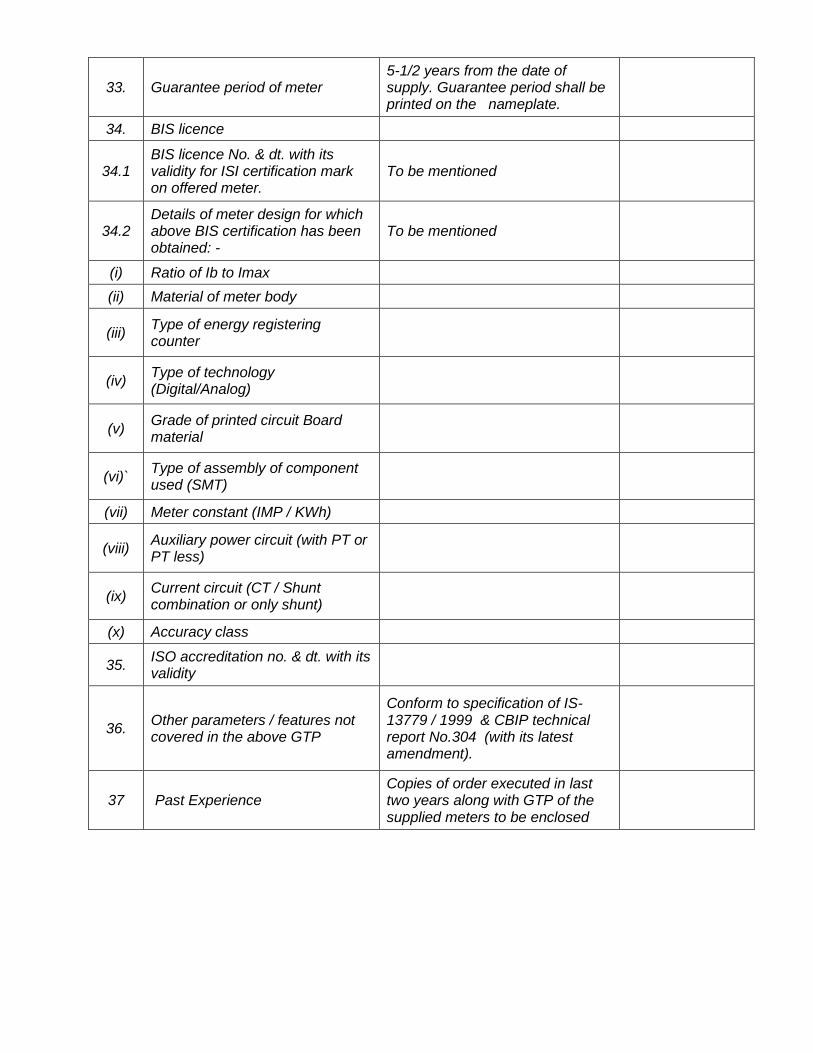
33. Guarantee period of meter 5-1/2 years from the date of supply. Guarantee period shall be printed on the nameplate.
34. BIS licence
34.1 BIS licence No. & dt. with its validity for ISI certification mark on offered meter.
To be mentioned
34.2 Details of meter design for which above BIS certification has been obtained: -
To be mentioned
(i) Ratio of Ib to Imax
(ii) Material of meter body
(iii) Type of energy registering counter
(iv) Type of technology (Digital/Analog)
(v) Grade of printed circuit Board material
(vi)` Type of assembly of component used (SMT)
(vii) Meter constant (IMP / KWh)
(viii) Auxiliary power circuit (with PT or PT less)
(ix) Current circuit (CT / Shunt combination or only shunt)
(x) Accuracy class
35. ISO accreditation no. & dt. with its validity
36. Other parameters / features not covered in the above GTP
Conform to specification of IS-13779 / 1999 & CBIP technical report No.304 (with its latest amendment).
37 Past Experience Copies of order executed in last two years along with GTP of the supplied meters to be enclosed

Annexure - II
Pre-Qualification Conditions for Single Phase Static Meters
Sl. No. Particulars Remarks
1 Bidders must have valid BIS certification for the offered meter.
Yes / No
2 Bidder preferably posses ISO 9001 certification Yes / No
3
Bidder should be manufacturers of static meters having supplied Static 1-ph or 3-phase meters with memory and LCD display to Electricity Boards / Utilities in the past 3 years
Yes / No
4 Bidder has Type Test certificate for the Type of offered meter not more than 3 (three) years old
Yes / No
5 Bidders should have dust free, static protected environment for manufacture, assembly and Testing.
Yes / No
6 Bidder should have automatic computerized test bench for lot testing of meters.
Yes / No
7 Bidder has facilities of Oven for ageing test. Yes / No
8
Bidder shall submit certificate for immunity against magnetic influence of 0.2 T AC. & 0.5 T DC. from a NABL accredited Laboratory, for the same type of meter as offered.
Yes / No

Annexure - III
Sl. No.
Component Function /
Feature As per Requirement Make / origin
1 Current Element
2 Measurement /
Computing chips
3 Memory chips
4 Display modules
5 Communication
modules
6 Optical port
7 Power Supply
8 Electronic
components
9 Mechanical parts
10
Battery
11 RTC / Micro
controller
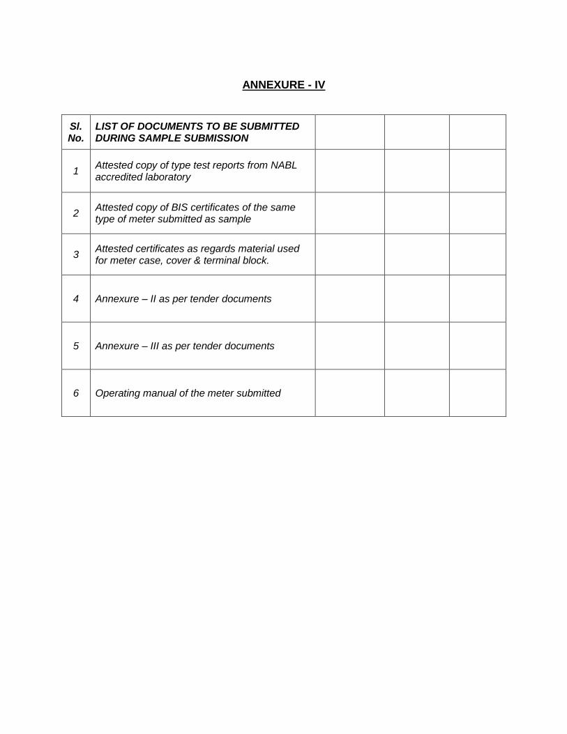
ANNEXURE - IV
Sl. No.
LIST OF DOCUMENTS TO BE SUBMITTED DURING SAMPLE SUBMISSION
1 Attested copy of type test reports from NABL accredited laboratory
2 Attested copy of BIS certificates of the same type of meter submitted as sample
3 Attested certificates as regards material used for meter case, cover & terminal block.
4 Annexure – II as per tender documents
5 Annexure – III as per tender documents
6 Operating manual of the meter submitted

ANNEXURE - IVA
Reference:
Date of Test :- Name of bidder / Manufacturer:
Address:-
Description of Meter :- Serial No Impulse/Kwh
Type Class
Voltage Mfg. Dt.
Current
Test Performed:-
Sl. No. Description of Test
1.) Meter subjected to 450V between Phase and Neutral for 4 hours:
Result:-
Meter terminals subjected to 150% Imax for 2 hours.
Result:-
2.) Insulation Resistance Result:- Measured Points Limit ( Min. )
Obs. Values
Between Frame & Phase Circuit
Between Frame & Neutral Circuit
3.) Power Loss: Measured
Points Limit
Obs. Values
Voltage Circuit
Watt 1.0
VA 4.0
Current Circuit VA 1.0
4.) No Load Limit Obs. Values
120% of Rated Voltage Result:- Max. 1 pulse
70% of Rated voltage Result:- Max. 1 pulse
5.) Starting Current
0.2% of Ib Result:- Limit Observation
< 10 minutes.

6.) Description of Test:
Limits of Error Load P.F. Errors as per
IS13779 / CBIP304
%Error for Active Phase
% Error For Active Neutral
Imax 1.0 (±) 1%
0.5 lag (±) 1%
0.8 ld (±) 1%
200% Ib 1.0 (±) 1%
0.5 lag (±) 1%
Ib 1.0 (±) 1%
0.5 lag (±) 1%
0.8 ld (±) 1%
50% Ib 1.0 (±) 1%
0.5 lag (±) 1%
0.8 ld (±) 1%
10%Ib 1.0 (±) 1%
0.5 lag (±) 1.2%
0.8 ld (±) 1.2%
5%Ib 1.0 (±) 1%
0.5 lag (±) 2%
0.8 ld (±) 2%
2%Ib 1.0 (±) 2%
1%Ib 1.0 (±) 2%
7.) Repeatability of Error 1 2 3 4 5 6 Diff
Load 5% Ib UPF
1 2 3 4 5 6 Diff
Load 100% Ib UPF
Reproducibility of Error 1 2 3 4 5 6 Diff
Load 5% Ib UPF
1 2 3 4 5 6 Diff
Load 100% Ib UPF
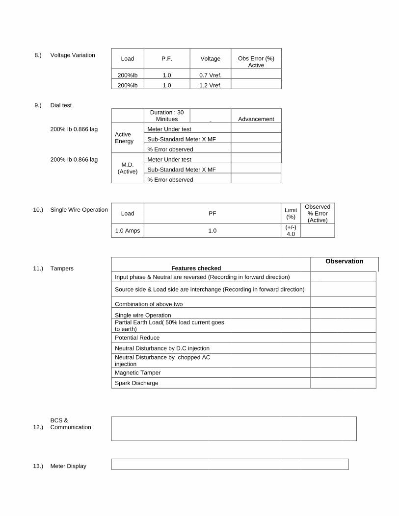
8.) Voltage Variation Load P.F. Voltage Obs Error (%)
Active
200%Ib 1.0 0.7 Vref.
200%Ib 1.0 1.2 Vref.
9.) Dial test
Duration : 30
Minitues Advancement
200% Ib 0.866 lag Active Energy
Meter Under test
Sub-Standard Meter X MF
% Error observed
200% Ib 0.866 lag M.D.
(Active)
Meter Under test
Sub-Standard Meter X MF
% Error observed
10.) Single Wire Operation Load PF
Limit (%)
Observed % Error (Active)
1.0 Amps 1.0
(+/-) 4.0
11.) Tampers Features checked
Observation
Input phase & Neutral are reversed (Recording in forward direction)
Source side & Load side are interchange (Recording in forward direction)
Combination of above two
Single wire Operation Partial Earth Load( 50% load current goes to earth)
Potential Reduce
Neutral Disturbance by D.C injection
Neutral Disturbance by chopped AC injection
Magnetic Tamper
Spark Discharge
12.) BCS & Communication
13.) Meter Display

14.) Physical Examination
15.) General Remarks
Signature of
Manufacturer’s Witness Representative of WBSEDCL
Representative.


TECHNICAL SPECIFICATION FOR PILFER PROOF METER BOX SUITABLE FOR SINGLE PHASE STATIC ENERGY METER
1.0 SCOPE:
1.1 This specification covers manufacture and supply of Pilfer Proof Meter Box (PPMB) suitable to house Single Phase Static Energy Meter. The Meter Box shall be wall mounted type. ability so as to offer protection of electrical equipment against harsh weather. The box shall be anti-corrosive, dust proof, shock, vermin & waterproof, pilfer proof, fire proof and UV stabilized. The enclosures shall not deform or melt when exposed to fire.
2.0 TECHNICAL REQUIREMENT :
2.1 The Meter Box i.e base and cover shall be made of hot press/injection moulded, unbreakable, high grade fire retardant Engineering Plastic (Acrylonitrile Butadiene Styrene)/Polycarbonate, with minimum thickness 2.0 mm having good di-electric and mechanical strength. The material must be such that the Meter Box should not change in colour, shape. size, dimensions when subjected to Ageing Test. The Meter Box should have top tapered surface and round corners to prevent any water logging on the top of meter cover. The overall dimensions of the enclosure shall be suitable for housing single phase meter as offered by the bidder and there should be a clearance of 30 + 2 mm from top & both sides of the meter. Bottom side clearance should be 75 + 5 mm from the lower edge of terminal block of the meter. Clearance from front side and back side of the meter should be 15 + 2 mm and 10 + 2 mm respectively. Meter Box with higher dimensions may be considered if found suitable.
2.2 The Meter Box should be capable of withstanding the mechanical, electrical and thermal stresses well as the effects of humidity which are likely to be encountered in service. At the same time the box should ensure desired degree of safety. The material used should be adequately stabilized against detrimental effect of light and weather. The surface appearance of the moulded parts must be smooth, non-porous and homogeneous, free of ripples, defects and marks. No fillers of fibers should be visible at any place.
2.3 The box should comply in all respect with the requirement of latest amendments of IS /ASTM. Applicable degree of protection shall be IP 42 or better.
2.4 All accessories like nuts, bolts, washers etc. shall be galvanized.
3.0 CONSTRUCTION :
3.1 The enclosure shall be single piece moulded with hot process compression moulding or injection moulding.
3.2 Dimension : To be specified by the bidder.
3.2 Hinges :
A minimum of 2 nos. brass/stainless steel hinges in left side of the door and 1 no. brass/stainless steel hinge/stainless steel U type latch with locking arrangement in right side of the door shall be provided inside the enclosure. The hinges of the door shall be concealed and they shall be fixed to the flanges provided on the body and cover of the enclosure in such a manner that the door opens by a minimum of 120 degrees.
3.3 Suitable grove with locking arrangement shall be provided for opening of the enclosure door.
3.4 Earthing Bolt :
8mm dia. G.I. bolt with 2 nos. washers for earthing all metal parts shall be provided.
3.5 Fixing arrangement :
The meter box shall have 4 nos. of mounting brackets made out of same material as meter box with provision for 6 mm dia hole for mounting the box on the wall or wooden board with suitable screws. The meter box shall have provision to fix it on the wall or wooden board with the meter in assembled condition. Four (4) nos. self threaded screws of minimum size of 4 mm dia and 25 mm long shall be provided with each meter box. Any other suitable arrangement for fixing the box may be accepted after verification.

3.6 Sealing arrangement :
The Box should have provision for padlocking and also for sealing arrangement of the base with cover providing holes for 1 no. seal to make it fully tamper proof.
3.7 Incoming and outgoing cable arrangement :
Suitable 2 (two) Nos. of holes at bottom (12 mm. dia) shall be provided in the box for cable/wire entry. 2 (two) holes must be totally covered with neoprene rubber gasket (NRG). NRG will be punched for entry of incoming and outgoing cable/wire.
3.8 Base and Cover details :
Thickness of the meter box shall not be less than 2.0 mm on all sides including door. The meter box shall have 4 mm thickness of the tongue and groove area. The meter box cover shall be made overlapping type having collars on all four (4) sides and shall be provided with Neoprene rubber gasket of minimum 2.5 mm dia to completely fit in the grooves of the base. The base of the meter box must have a groove to hold the gasket and the overlap of the top cover with base should be sufficient. The tongue of the base shall ensure proper sealing arrangement against ingress of rainwater and dust inside the box.
3.9 The Enclosures shall generally comply with the provision of IS 14772 or IEC 695. The enclosures shall be suitable for outdoor application. The enclosure shall be with good workmanship.
3.10 Soft neoprene/nitride rubber gaskets shall be provided all round wherever required for protection against entry of dust and water. The gasket shall confirm to Type-III as per IS-11149. The enclosure shall comply with IP-42 or better degree of protection.
3.11 The Enclosures shall be off white/admiral gray / ivory/ transparent polycarbonate.
3.12 Marking/Embossing:
The following information shall be clearly & indelibly embossed/laser printed on the cover and base of the Meter Box. The top & bottom corner of Meter Box Sl. No. shall be same for the particular Meter Box.
i) Property of WBSEDCL ii) Name/Brand name of Manufacturer iii) Meter Box Sl. No. (Embossed / laser printing on both the base and covers of Meter Box) iv) Sign of Danger
4.0 Submission of Sample :
4.1 The bidder shall submit a sample Meter Box as per our specification along with the sample meter to the office of the Chief Engineer, (DTD), Abhikshan Bhavan, Sector-V, Salt Lake, Kolkata-91 before the last day of submission of bid.
4.2 Submission of sample meter box as per size available with the bidder but conforming to our specification towards its quality is acceptable . Type testing including material identification (IR Spectrometry test) of one meter box manufactured as per specification is to be conducted at any NABL accredited laboratory/CIPET by the supplier at their own cost after placement of order. For type testing the meter box will be selected from the first offered lot of meter with meter box. If the type test results are not found satisfactory, the offered lot of meter along with meter box will be rejected.
5.0 Quality Control:
5.1 Type test reports from CIPET/NABL accredited laboratory as per Standard IS/ASTM shall be submitted. The type test reports shall not be more than 5 (five) years old. Acceptance tests as per IS/ASTM are to be carried out by the supplier in presence of WBSEDCL‟s representative. Material of meter enclosure shall be tested for Heat Deflection Temperature, Exposure to Flame (Self-extinguishing) and Resistance to Heat & Fire (Glow wire) as per specification and Ref. Standard IS/ASTM.
6.0 General Construction Requirement: 6.1 Viewing Window:
A viewing window as per drawing made up of scratch and break resistant, UV resistant, transparent Polycarbonate material shall be provided on the door for reading the meter without inconvenience. The
minimum thickness of the viewing window shall be 2.0 mm.(flashing with top). The viewing window shall be provided with fixed rain hood. The window shall be securely fixed with meter enclosure from inside. Suitable neoprene gasket shall be provided so that there shall not be any ingress of moisture through this window into the enclosure. No viewing window is required for transparent polycarbonate meter box.
6.2 Construction of louver: Louver must be provided in one side of the pilfer proof box inside of which must be covered with the mesh
(plastic) in such a way that from outside that mesh can not be approached. No louver is required for transparent polycarbonate meter box.
6.3 6.3 One push button is to be provided on the front side of the top cover of meter box for taking meter reading
during power off condition without opening of meter box cover.
7.0 Guarantee: The Pilfer Proof Meter Box should be guaranteed against any manufacturing defects arising out of faulty design or bad workmanship or component failure for a period of 5 ½ years from the date of supply.
The meter box found defective within the above guarantee period shall be replaced by the supplier free of cost within one month of the receipt of intimation of failure/defect. Defective meter box are to be replaced by new one with new sl. nos. as allotted by C.E (DTD).
8.0 Replacement of defective Meter Box : The Meter Box declared defective by the WBSEDCL shall be replaced by the supplier up to the full
satisfaction of the WBSEDCL at the cost of supplier. Failure to do so within the time limit prescribed shall lead to imposition of penalty of twice the cost of meter box. The same may lead to black listing even, as decided by WBSEDCL. In this connection the decision of WBSEDCL shall be final.
9.0 Testing: a) Type Test:
The bidder must furnish type test report including material verification of the offered/sample meter box
from any NABL/Govt. approved laboratory as available with them along with technical bid without which the offer will not be considered. Type test report should not be more than 5 (five) years old. Type testing at any recognized NABL accredited laboratory/CIPET in respect of one meter box as per the specified size, selected from any one of the offered lot during supply is to be conducted by the supplier at their own cost after placement of order for verification of material and quality of the box. If the type test results are not found satisfactory, the offered lot of meter along with the meter box will be rejected.
b) Acceptance Test:
The acceptance test as stipulated in Annexure-VI shall be carried out at the time of inspection of the offered material.
c) Routine Test: The routine tests as stipulated in the Annexure-VI shall be carried out and routine test certificate
/reports shall be submitted to Chief Engineer (DTD), WBSEDCL,Abhikshan,Sector-V, Salt Lake City, Kolkata-700091 while offering inspection & testing of the meter with meter box.
Notes: 1) Where facilities do not exist at supplier‟s works for carrying out one or more of the Acceptance Tests as per Annexure-VI, such tests may be carried out at any of the approved laboratories such as CIPET/IIT/National Test House/Govt. approved laboratory etc. in presence of WBSEDCL‟s representative.
2) The sampling plan for carrying out the acceptance tests shall be as per IS.
10.0 Submission of Drawing:
Three (3) copies of drawing complete in all respect should be submitted to the C.E (DTD) under intimation to the Material Controller for accordance of approval immediately after placement of order. 25 copies of approved drawing are to be submitted for distribution to sites.
11.0 Inspection: The inspection will be carried out as per inspection & testing clause of General Conditions of Contract (GCC).
12.0 Guaranteed Technical Particulars:
The bidder shall furnish all the necessary information as per Annexure-VII - Guaranteed Technical Particulars. If the bidder desire to furnish any other information in addition to the details as asked for, the same may be furnished.

ANNEXURE-V
LIST OF TESTS TO BE CARRIED OUT ON SINGLE PHASE METER BOX
Sl. No.
Name of Indian standard/equivalent international standard
Test requirement Test particulars
Type test Routine Test
Acceptance Test
1. IS : 14772 Marking T A
2. As per Drawing Dimensions T R A
3. IS / ASTM Protection against electric shock
T R A
4. IS / ASTM Construction T R A
5. IS / ASTM Resistance to ageing, to humid conditions, to ingress of solid object and to harmful ingress of water
T
6. IS / ASTM Mechanical strength T
7. IS / ASTM Resistance to heat T
8. IS / ASTM Resistance to rusting T
9. IS / ASTM Resistance to tracking T
10. IS / ASTM Test for resistance to heat & fire (Glow wire test at 6500 C)
T
11. IS / ASTM Heat deflection temp. @ 1.8 MPa-1000 C (Minm. for Engg. Plastic)/1400 C (Minim. for Polycarbonate
T R
12. IS / ASTM Self Extinguishing property of spirit burner test.
T R A
13. IS / ASTM Melting point-1800 C (Minimum for Engg. Plastic)/2100 C (Minimum for Polycarbonate)
T
14. IS / ASTM Verification of di-electric properties, insulation test with 500V DC magger
T
15. CIPET/IR Spectrometry
Material identification T
16. IS / ASTM Physical water absorption (Max. 0.35%)
T
Note : Applicable degree of protection shall be IP42 or better. Legend : T- Type Test, R- Routine Test, A- Acceptance Test
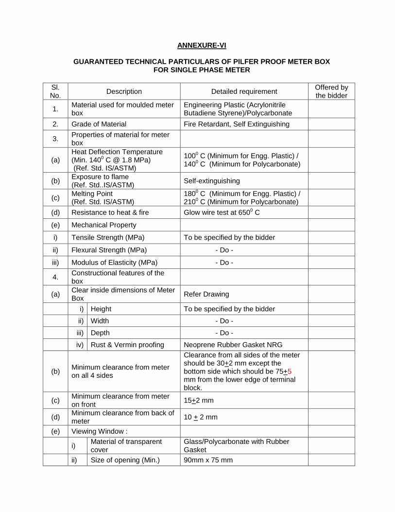
ANNEXURE-VI
GUARANTEED TECHNICAL PARTICULARS OF PILFER PROOF METER BOX FOR SINGLE PHASE METER
Sl. No.
Description Detailed requirement Offered by the bidder
1. Material used for moulded meter box
Engineering Plastic (Acrylonitrile Butadiene Styrene)/Polycarbonate
2. Grade of Material Fire Retardant, Self Extinguishing
3. Properties of material for meter box
(a) Heat Deflection Temperature (Min. 1400 C @ 1.8 MPa) (Ref. Std. IS/ASTM)
1000 C (Minimum for Engg. Plastic) / 1400 C (Minimum for Polycarbonate)
(b) Exposure to flame (Ref. Std..IS/ASTM)
Self-extinguishing
(c) Melting Point (Ref. Std. IS/ASTM)
1800 C (Minimum for Engg. Plastic) / 2100 C (Minimum for Polycarbonate)
(d) Resistance to heat & fire Glow wire test at 6500 C
(e) Mechanical Property
i) Tensile Strength (MPa) To be specified by the bidder
ii) Flexural Strength (MPa) - Do -
iii) Modulus of Elasticity (MPa) - Do -
4. Constructional features of the box
(a) Clear inside dimensions of Meter Box
Refer Drawing
i) Height To be specified by the bidder
ii) Width - Do -
iii) Depth - Do -
iv) Rust & Vermin proofing Neoprene Rubber Gasket NRG
(b) Minimum clearance from meter on all 4 sides
Clearance from all sides of the meter should be 30+2 mm except the bottom side which should be 75+5 mm from the lower edge of terminal block.
(c) Minimum clearance from meter on front
15+2 mm
(d) Minimum clearance from back of meter
10 + 2 mm
(e) Viewing Window :
i) Material of transparent cover
Glass/Polycarbonate with Rubber Gasket
ii) Size of opening (Min.) 90mm x 75 mm
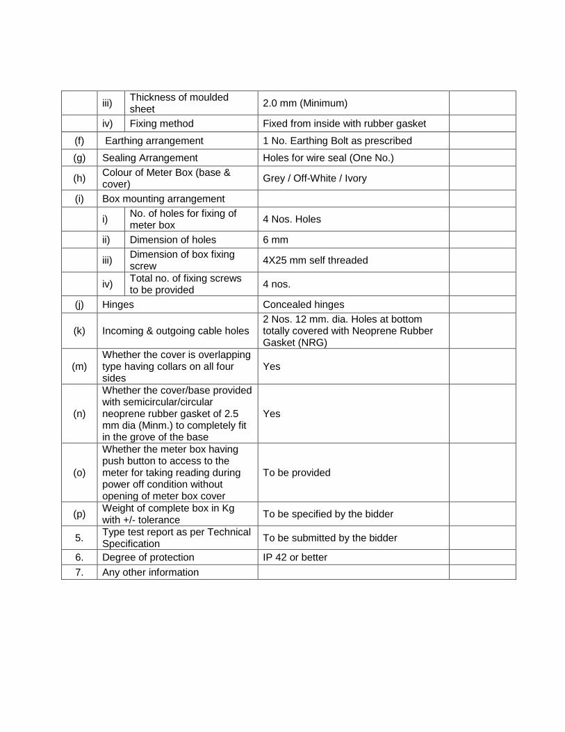
iii) Thickness of moulded sheet
2.0 mm (Minimum)
iv) Fixing method Fixed from inside with rubber gasket
(f) Earthing arrangement 1 No. Earthing Bolt as prescribed
(g) Sealing Arrangement Holes for wire seal (One No.)
(h) Colour of Meter Box (base & cover)
Grey / Off-White / Ivory
(i) Box mounting arrangement
i) No. of holes for fixing of meter box
4 Nos. Holes
ii) Dimension of holes 6 mm
iii) Dimension of box fixing screw
4X25 mm self threaded
iv) Total no. of fixing screws to be provided
4 nos.
(j) Hinges Concealed hinges
(k) Incoming & outgoing cable holes 2 Nos. 12 mm. dia. Holes at bottom totally covered with Neoprene Rubber Gasket (NRG)
(m) Whether the cover is overlapping type having collars on all four sides
Yes
(n)
Whether the cover/base provided with semicircular/circular neoprene rubber gasket of 2.5 mm dia (Minm.) to completely fit in the grove of the base
Yes
(o)
Whether the meter box having push button to access to the meter for taking reading during power off condition without opening of meter box cover
To be provided
(p) Weight of complete box in Kg with +/- tolerance
To be specified by the bidder
5. Type test report as per Technical Specification
To be submitted by the bidder
6. Degree of protection IP 42 or better
7. Any other information

ANNEXURE - VII
TESTING
1. Sample selected from first lot should be type tested at any NABL accredited laboratory for compliance of performance parameters as given in GTP including material identification to be carried out by CIPET (IR Spectrometry test).
2. The test report should be submitted to WBSEDCL before delivery of
3. Inspection of each lot & sampling plans for acceptance test : 1 no. selected randomly from lot for testing at works.
Sl. No.
Test Requirement for moulded meter box Reference Standards
a) Marking IS /ASTM
b) Dimensions & construction IS /ASTM
c) Heat Deflection Temperature - 1450 C at no pressure (Minimum)
IS /ASTM
d) Spirit Burner Test (Self Extinguishing) IS /ASTM
e) Melting point - 1300 C at no pressure (Minimum) IS /ASTM