TECHNICAL SPECIFICATIONS FOR EARTH WORK ...nscdelhi.org/content_image/AddendumforPalampur.pdfA. Item...
39
Kothari & Associates Kolkata. 1 of 26 TECHNICAL SPECIFICATIONS FOR EARTH WORK, CONCRETE WORK, BRICK WORK, PLASTER AND ALLIED WORKS IN SUB‐STRUCTURE & SUPER‐STRUCTURE. I. GENERAL Specifications, Scope of Work, Schedule of Rates and drawings for a particular Tender shall be read in conjunction with each other. In case of conflicts / contradictions amongst them, the clarification shall be obtained from the Engineer – in – Charge / Architect whose decision shall be final & binding. Following procedure shall be followed for the necessary clarification. A. Item description shall prevail over specifications for item rate tenders when provisions therein are different from those in specifications. Whenever any requirement is not covered in Item description but are covered in specifications, the specifications shall be followed in addition to the requirements of item description. No extra payment shall be made to the Contractor for executing such item as per specification. B. Whenever drawings call for requirements different from or additional to those in item description and specification, the decision of the Engineer – in – Charge shall be obtained. However no extra payment shall be made to the Contractor for executing any work incorporating requirements additional to those in item description and specification but covered in applicable drawings or standards. Where ever references has been made to Indian Standard or any other specifications the same shall mean to refer to the latest specifications irrespective of any particular edition of such specifications being mentioned in the specifications below of Schedule of Quantities. C. The cost of Cement, Reinforcement steel, structural Steel, Bricks, Coarse and Fine Aggregates, and other requisite materials and labour Charges and other incidental expenses to be needed for the Construction of Store, Site Office etc to be borne by the Contractor. II. WORKMANSHIP Workmanship shall be to the satisfaction of the Engineer – in – Charge / Architect. The contractor shall follow the specifications, relevant Codes & Manufacturer’s guidelines for achieving desired level of workmanship as per specification & good engineering practice. Any executed work not conforming to the specification or not to the satisfaction of the Engineer – in – Charge / Architect shall be rectified by the Contractor as directed by the Engineer – in – Charge / Architect. No extra payment shall be made to the Contractor for such rectification. III. MEASUREMENT Mode of measurement is generally specified in each specification. Whenever mode of measurement is not specified, IS: 1200 shall be applicable. IV. MATERIALS General (a) All materials shall be best of their kind and shall conform to the latest Indian Standard. (b) All materials shall be of approved quality as per samples and from origins approved by the Engineer–in‐Charge / Architect. The Contractor shall get the materials approved by the Engineer – in – Charge / Architect before ordering & procurement. The Contractor shall furnish necessary certificates etc. as asked by the Engineer – in – Charge. Further to that he shall get the materials tested from approved test house if asked by the Engineer‐in‐Charge & submit the test certificate at his own cost for which no extra payment shall be made to him. The Engineer – in – Charge shall have the right to reject all or any of the materials intended to be used and such materials shall be immediately removed from the site by the Contractor at his own cost without any claim for compensation etc. due to such rejection. (c) A set of specimen samples of all approved materials shall be kept in bottle or wise at site, cost of which to be borne by the Contractor. (d) Test reports on each manufactured materials shall include a statement certifying that this material is of the same quality as that proposed for this project. Manufacturer's literature on proprietary materials shall indicate compliance with standards listed here in. 1. Cement: Unless otherwise specifically called for, Cement for RCC and PCC / lean concrete works shall be one of the following: The type of cement selected shall be appropriate for the intended use. 33 grade ordinary or low heat Portland Cement IS:269 43 grade ordinary Portland Cement IS:8112 Portland slag Cement IS:455 Portland Pozzolana Cement (fly ash based) IS:1489 (Part – I) Portland Pozzolana Cement (calcined clay based) IS:1489 (Part – 2) Sulphate resisting Portland Cement IS:12330 High aluminia Cement IS:6452 These different cements shall not be used interchangeable in the same element or portion of the work.
-
Upload
nguyenhanh -
Category
Documents
-
view
224 -
download
3
Transcript of TECHNICAL SPECIFICATIONS FOR EARTH WORK ...nscdelhi.org/content_image/AddendumforPalampur.pdfA. Item...

Kothari & Associates Kolkata.
1 of 26
TECHNICAL SPECIFICATIONS FOR EARTH WORK, CONCRETE WORK, BRICK WORK, PLASTER AND ALLIED WORKS IN SUB‐STRUCTURE & SUPER‐STRUCTURE.
I. GENERAL
Specifications, Scope of Work, Schedule of Rates and drawings for a particular Tender shall be read in conjunction with each other. In case of conflicts / contradictions amongst them, the clarification shall be obtained from the Engineer – in – Charge / Architect whose decision shall be final & binding. Following procedure shall be followed for the necessary clarification. A. Item description shall prevail over specifications for item rate tenders when provisions therein are different from those in
specifications. Whenever any requirement is not covered in Item description but are covered in specifications, the specifications shall be followed in addition to the requirements of item description. No extra payment shall be made to the Contractor for executing such item as per specification.
B. Whenever drawings call for requirements different from or additional to those in item description and specification, the decision of the Engineer – in – Charge shall be obtained. However no extra payment shall be made to the Contractor for executing any work incorporating requirements additional to those in item description and specification but covered in applicable drawings or standards. Where ever references has been made to Indian Standard or any other specifications the same shall mean to refer to the latest specifications irrespective of any particular edition of such specifications being mentioned in the specifications below of Schedule of Quantities.
C. The cost of Cement, Reinforcement steel, structural Steel, Bricks, Coarse and Fine Aggregates, and other requisite materials and
labour Charges and other incidental expenses to be needed for the Construction of Store, Site Office etc to be borne by the Contractor.
II. WORKMANSHIP
Workmanship shall be to the satisfaction of the Engineer – in – Charge / Architect. The contractor shall follow the specifications, relevant Codes & Manufacturer’s guidelines for achieving desired level of workmanship as per specification & good engineering practice. Any executed work not conforming to the specification or not to the satisfaction of the Engineer – in – Charge / Architect shall be rectified by the Contractor as directed by the Engineer – in – Charge / Architect. No extra payment shall be made to the Contractor for such rectification.
III. MEASUREMENT
Mode of measurement is generally specified in each specification. Whenever mode of measurement is not specified, IS: 1200 shall be applicable.
IV. MATERIALS
General (a) All materials shall be best of their kind and shall conform to the latest Indian Standard.
(b) All materials shall be of approved quality as per samples and from origins approved by the Engineer–in‐Charge / Architect. The
Contractor shall get the materials approved by the Engineer – in – Charge / Architect before ordering & procurement. The Contractor shall furnish necessary certificates etc. as asked by the Engineer – in – Charge. Further to that he shall get the materials tested from approved test house if asked by the Engineer‐in‐Charge & submit the test certificate at his own cost for which no extra payment shall be made to him. The Engineer – in – Charge shall have the right to reject all or any of the materials intended to be used and such materials shall be immediately removed from the site by the Contractor at his own cost without any claim for compensation etc. due to such rejection.
(c) A set of specimen samples of all approved materials shall be kept in bottle or wise at site, cost of which to be borne by the Contractor.
(d) Test reports on each manufactured materials shall include a statement certifying that this material is of the same quality as that
proposed for this project. Manufacturer's literature on proprietary materials shall indicate compliance with standards listed here in. 1. Cement:
Unless otherwise specifically called for, Cement for RCC and PCC / lean concrete works shall be one of the following: The type of cement selected shall be appropriate for the intended use.
33 grade ordinary or low heat Portland Cement IS:269
43 grade ordinary Portland Cement IS:8112
Portland slag Cement IS:455
Portland Pozzolana Cement (fly ash based) IS:1489 (Part – I)
Portland Pozzolana Cement (calcined clay based) IS:1489 (Part – 2)
Sulphate resisting Portland Cement IS:12330
High aluminia Cement IS:6452
These different cements shall not be used interchangeable in the same element or portion of the work.

Kothari & Associates Kolkata.
2 of 26
Cement shall be further classified according to the compressive strength of cement at the age of 7 days as given in table 4.1.
Table 4.1 Cement type Compressive strength of cement at the age of 198+2Hrs A Not less than 22N/mm2 B Not less than 26N/mm2 C Not less than 30N/mm2 D Not less than 33N/mm2 Cement bags must be stored in a water‐tight shed having wooden floor or raised platform as approved by the Engineer‐in‐charge. Cement which is partially set or which is lumpy or caked is to be treated as damaged and shall be removed from the site immediately. Cement shall be stored in weather‐tight buildings, bins or silos, which will exclude moisture and contaminants. Storage of cement at site shall be at contractors expense and risk, in the event of any damage occurring to cement due to faulty storage in Contractor's shed or on account of negligence on his part, such damages shall be the liability of the Contractor. In case cement is stored and stacked in bags, storing shall be done in weather‐tight and properly ventilated structures to prevent absorption of moisture. The bags shall be stacked at least 10 to 20 cm. clear above the floor. A space of 60 cms. all‐round should be kept between the exterior walls and the stacks. Cement bags should be placed close together in the stacked to reduce circulation of air as much as possible. Cement bags shall not be stacked more than 10 bags high to avoid lumping under pressure . If the stack is more than 7 bags high, arrange the bags in header and stretcher fashion that is alternatively length‐wise and cross‐wise so as to tie them together and lessen the danger of toppling over. For extra safety during the monsoon or when it is expected to store the cement for an unusually long period, enclose the stack completely in 700 gauge polythene sheet or any other suitable waterproof material. The flap will close on the top of the stack. Care should be taken that the polythene sheet is not damaged any time during use. Where removing bags from storage should be removed from two or three tiers back rather than all from one tier. If the rows are thus stepped back, there is less chance of over turning them. When removing cement bags for use apply the first in, first out, rule, that is, take the oldest cement out first. Each consignment of cement shall be stacked separately therein to permit easy access for inspection and facilitate removal.
2. M.S Reinforcement: All steel bars, sections, plates and other miscellaneous steel materials, etc. shall be free from loose mill scales, dust, loose rust as well as oil, mud, paint or other coatings. The materials, construction, specifications such as dimensions, shape, weight, tolerances, testing etc, for all materials covered under this section, shall conform to respective BIS code. Steel reinforcement shall be stored in a way as to prevent distortion and corrosion. Bars of different classifications, sizes and lengths shall be stored separately to facilitate issues in such sizes and lengths as to minimize wastage in cutting from standard lengths. High strength deformed (HSD) steel bars of minimum grade Fe 415, conforming to IS:1786 shall be used.
3. Structural Steel: Structural steel sections shall conform to following BIS Codes :
Steel tubes for structural purposes IS:1161
Mild Steel Tubes, tubular and other wrought steel fittings IS:1239
Steel for general structural purposes (Grade A). IS:2062
Hollow steel sections for structural use. IS:4923
4. Miscellaneous Steel Materials: Miscellaneous Steel Materials shall conform to the following BIS Codes:
Expanded Metal Steel Sheets for General purposes IS:412
Specification for mild steel and medium tensile steel bars and hard drawn steel wire for concrete reinforcement (Grade I) (For mild steel bars of anchor bolts, rungs, metal inserts, grating etc.)
IS:432
Hexagonal head bolts, screws & nuts of product Grade C IS:1363
Cold formed light gauge structural steel sections IS:811
Technical supply conditions for threaded steel fasteners IS:1367
Plain washers IS:2016
Steel wire ropes for general engineering purposes IS:2266
Thimbles for wire ropes IS:2315
Bulldog grips IS:2361
Mild Steel Tubes, tabular and other wrought steel fillings. (For Hand rail tubular sections).
IS:1239
Drop forged sockets for wire ropes for general engineering purposes.
IS:2485
Steel chequered plates IS:3502
Hexagonal bolts and nuts (M42 to M150) IS:3138

Kothari & Associates Kolkata.
3 of 26
Anchor Bolts: Materials for Anchor Bolts such as MS bars, washers, nuts, pipe sleeves and plates etc. shall be as per relevant BIS Codes mentioned above under Clause – 4.
5. Stone:
All stones used for masonry works shall conform to the requirements of following BIS Codes.
Method of identification of natural building stones IS:1123
Recommendations for dimensions and workmanship of natural building stones for masonry work
IS:1127
Recommendations for dressing of natural building stones IS:1129
Stones chips or stone ballast for cement concrete shall be hard, dense, strong, sound, durable, clean and uniform in colour. They shall also be free from veins, adherent coatings, injurious amounts of alkalis, vegetable matters and other deleterious substances such as iron pyrites, coal, lignite, mice, sea shells etc. as far as possible stones from one single quarry shall be used for anyone work. The strength of stones should be adequate to carry the imposed load and shall meet all the requirements of IS:1905, taking into account the appropriate crushing strength of stone and type of the mortar used. The percentage of water absorption, when tested in accordance with IS:1124, shall not exceed 5 percent. The length of the stone shall not exceed 3 times the height. Width of stone on base shall not be less than
150mm and in no case exceed ¾ thickness of the wall. Height of the stone shall not be more than 300 mm. Gravel, for use as coarse aggregates in cement concrete work must be hard, absolutely free from surface coating and on being broken, the fractured surface must indicate a uniform and fine texture free from laminations or planes or weakness. It shall be thoroughly washed and free from any foreign elements.
Jhama chips for cement concrete for cement concrete work shall be obtained by breaking good quality jhama bats, must be spongy or with any coating of foreign materials and should be homogenous in texture. The chips shall be more or less cubicle in shape. All coarse aggregates for concrete works must be well graded. These shall be screened for removal of dust and if so in the opinion of the
Engineer‐in‐charge, shall be washed at the cost and expenses of the Contractor. Aggregates stockpiles shall be arranged and used in manner to avoid excessive segregation and to prevent contamination with other sizes
of like aggregates. It shall be stacked separately according to nominal sizes of coarse aggregates in stacks of height not exceeding 1.5 metres. Frozen or partially frozen aggregates shall not be used.
6. Coarse aggregates for Lime concrete works:
i) Brick aggregates for lime concrete in foundation or flooring shall consist of approved, clean, hard and well‐ burnt jhama khoa. The khoa be well graded and unless otherwise specified shall pass through 32mm ring.
ii) Brick aggregates for lime terracing work on roof shall consist of khoa broken from first class brick bats and unless otherwise specified shall pass through 25mm ring and be suitably graded.
No jhama khoa should be used in lime terracing work. 7. Surki: Surki shall be made from well burnt 1
st class brick bats, ground to pass through a mesh 2mm, each way, and shall be perfectly clean and free from any foreign matter.
8. Lime:
All lime shall be freshly burnt and slaked and screened before use, the slaking should be done at site of work. Lime for work including roof terracing shall be Brisa, Satna or other approved stone lime. The specifications of lime as used in construction of building and other structures
a) Quick lime shall mean a Calcined material, the major part of which is calcium oxide in natural association with a relatively small amount of magnesium oxide and capable of slaking with water.
b) Fat lime shall mean the lime which has high calcium oxide content (between 95 to 100 percent) and this is dependent for setting and hardening on absorption of carbon dioxide from the atmosphere. This is defined as class‐C in IS: 712‐1973 which is used for finishing coat in plastering, white washing etc and with addition of pozzolanic materials (surki) for masonry mortar. c) Hydraulic lime shall mean the lime which contains small quantities of silica and alumina and iron oxide which are in chemical
combination with some of the calcium oxide content, giving a putty of mortar that has a property of setting and hardening under water.
d) Hydrated lime shall mean a dry powder resulting from treatment of quick lime with water enough to satisfy its chemical affinity for water under conditions of hydration.
Classifications of Lime: CLASS‐A: Eminently hydraulic lime (containing 25% to 30% of clay) used for foundations and other hydraulic structures, shall be supplied as hydrated lime only and should be used particularly in any masonry work below GL. It should be noted that no masonry
work below GL should be taken up with the use of any lime, other than specified hydraulic lime. In case of any doubt if any in respect of hydraulic lime being used in work below GL, it is preferable not to use lime mortar at all below GL.
CLASS‐C: Fat lime is used mainly for lime punning, white washing and with suitable admixture, such as surki or any other pozzolanic material to produce artificial hydraulic mortar.

Kothari & Associates Kolkata.
4 of 26
9. Sand: All sand shall be clean sharp and free from clay, loam, organic or any other foreign matter, shall be obtained from approved source. The Contractor shall get sample of sand to be used in different kinds of works approved by the Engineer‐in‐charge before using in the same work. Sand which in the opinion of the Engineer‐in‐charge dirty, must be washed to his satisfaction at the cost and expenses of the Contractor. Fine aggregates shall preferably be stacked in regular stacks on a hard surface or platform so as to prevent contamination with clay, dust, vegetation and other foreign matter. Fine aggregates stacks should be allowed to drain until it has reached a relatively uniform moisture content before it is used.
Coarse Sand: Shall be either river sand or pit – sand, clan, sharp, strong, angular and composed of hard Silicious materials. It shall be obtained from the quarries approved by the Engineer – in – Charge / Architects. The sand shall conform to relevant IS Code (IS:383). Fineness modules shall not be less than 2.5. The maximum quantity of silt shall not exceed 8%. Fine Sand: This shall be natural river sand. Fineness modules shall not be less than 1.0. The maximum quantity of silt shall not exceed 8%. The sand shall conform to relevant IS Specification (IS:383).
10. Stone Dust: It shall be obtained from crushing hard stones and from quarries approved by the Engineer – in – Charge / Architects. The fineness modulus
shall not be less than 1.8. The maximum quantity of silt shall not exceed 8%. 11. Bricks: Bricks for masonry works shall conform to IS:1077. Physical requirements, quality, dimension, tolerances etc. of common burnt clay
building bricks shall conform to the requirements of IS:1077. Bricks shall be hand – moulded or machine – moulded and shall be made from suitable soils. The bricks shall have smooth rectangular faces with sharp corners and shall be well burnt, sound, hard, tough and uniform in colour. These shall be free from cracks, chips, flaws, stone or humps of any kind. Testing of the bricks shall be done as per IS:5454 and IS:3495. Water absorption shall not be more than 20% by its dry weight when soaked in cold water for 24 hours.
12. Hollow (open & closed cavity) Concrete Block
The Hollow (open and closed cavity) Concrete Blocks shall conform to the following three grades; ( IS 2185 ‐ Part I ).
Grade A – These are used as load bearing units and shall have a minimum block density of 1500 kg/M3. These shall be manufactured for
minimum average compressive strengths of 3.5, 4.5, 5.5 and 7.0 N/mm2 respectively at 28 days .
Grade B – These are also used as load bearing units and shall have a block density less than 1500 kg/M3, but not less than 1000 kg/m3.
These shall be manufactured for minimum average compressive strengths of 2.0, 3.0 and 5.0 N/mm2 respectively at 28 days.
Grade C – These are used as non – load bearing units and shall have a block density less than 1500 kg/M3, but not less than 1000 kg/M3.
These shall be manufactured for minimum average compressive strength of 1.5 N/mm2 at 28 days.
Solid Concrete Blocks
Grade D – The solid concrete blocks are used as load bearing units and shall have a block density not less than 1800 kg/ M3. These shall be
manufactured for minimum average compressive strengths of 4.0 and 5.0 N/ mm2 respectively.
13. Admixtures: General Requirements For Admixtures: All concrete admixtures shall comply with the following Indian standards :
Specification for integral cement water proofing compounds IS:2645
Specification for other admixtures for concrete IS:9103
In case of non‐availability of any IS code for testing and acceptability Criteria, relevant American, British or German Code shall be applicable. No admixture shall impair the durability of the concrete nor combine with the ingredients to form harmful compounds nor increase the risk of corrosion of reinforcement. Use of admixture shall not reduce the dry density of concrete. Once the proportion of admixtures have been established, strict check shall be maintained not to alter the proportion of ingredients and water‐cement ratio of the Design Mix during execution. The chloride contains in admixtures shall not exceed 2% by mass of the admixture or 0.03% by mass of the cement. Admixtures to be used in concrete when required or permitted shall conform to the appropriate specification given in the reference publication. Admixtures used in work shall be of same composition as used in establishing the required concrete proportions. 14. Water Proofing Compounds: The permeability of the specimen with the admixture shall be less than half of the permeability with a similar specimen without the use of these compounds. These compounds shall be used in such proportion as recommended by manufacturer but in no case it shall exceed 3% by weight of cement. The initial setting time of the cement with the use of these compounds shall not be less than 30 minutes and final setting time shall not be more than 10 hours. Tests shall be carried out in accordance with IS:4031. Compressive strength of the specimen at 3 days shall not be less than 160 Kg/cm2 nor 80% of the 3 days compressive strength of mortar cubes prepared with same cement and sand only, whichever is higher. Similarly compressive strength at 7 days shall not be less than 220 Kg/Cm2 nor

Kothari & Associates Kolkata.
5 of 26
less than 80 % of the 7 days compressive strength prepared with the same cement and sand only, whichever is higher. The test to determine the compressive strength shall conform to IS:4031. 15. Wood / Timber: All timbers shall be of best quality well seasoned and / or well treated for preservation and protection against decay etc. it shall be uniform in substance, straight in fibre, free from large or dead knots, sap, flaws, sun‐cracks, shakes or blemishes of any kind. Any insect damage or splits across the grain shall not be permissible. The colour of the timber shall be uniform throughout, firm and shining with silky luster when planed and shall not emit dull sound when stuck. Timber required to be used for form work shall be fairly dry before use. It should maintain its shape during the use and even when it comes into contact with moisture from the concrete. Storage of wood/Timber shall be as per the requirements of IS:4082. 16. Water Water used for mixing and curing shall conform to requirements as specified in IS‐456. 17. PVC Pipes
PVC Pipes shall conform to the requirements of IS:4985. 18. Poly‐Sulphide Sealants: All Poly‐sulphide Sealants shall conform to IS:12118. Test conditions and requirements shall be as given in the above referred BIS code. V. SCOPE OF WORK All works shall be carried out in proper manner according to the directions of the Engineer‐in‐charge and to his satisfaction. Unless and otherwise specified in this section or in the description of the item, the cost of all, stages of works mentioned hereunder shall be deemed to have been included in the rates of items provided in the schedule. 1. ANTI‐TERMITE TREATMENT: Prevention of the termite from reaching the super‐structure of the building and its contents can be achieved by creating a chemical barrier between the ground, from where the termites come and other contents of the building which may from food for the termites. This is achieved by treating the soil beneath the building and around the foundation with a suitable insecticide. Materials – Chloropyrofos emulsifiable concentrates (1%) conforming to IS:8944 shall be used for treatment of soil for protection of buildings against attack by subterranean termites. Chemicals are available in concentrated form in the market and concentration is indicated on the sealed containers. Graduated containers shall be used for dilution of chemicals with water in the required proportion to achieve the desired percentage of concentration. Chemicals shall be brought to site of work in sealed original containers. The material shall be bought in a time in adequate quantity to suffice for the whole or at least a fort‐night’s work. Pre‐Construction Chemical Treatment‐ his is process in which chemical treatment is applied to a building in the early stages of its construction. Hand operated pressure pump shall be used for uniform spraying of the chemical. To have proper check for uniform spraying of chemical, graduated containers shall be used. Time Of Application – Soil treatment should start when foundation trenches and pits are ready to take mass concrete in foundations, laying of mass concrete should start when the chemicals emulsion has been absorbed by the soil and the surface is quite dry. Treatment should not be carried out when it is raining or soil is wet with rain or sub‐soil water. The foregoing applies also in the case of treatment to the filled earth surface within the plinth before laying the sub‐grade for the floor. Disturbance – The treated soil barriers shall be disturbed after they are formed. If by chance, treated soil barriers are disturbed, immediate steps shall be taken to restore by continuity and completeness of the barrier system.
Treatment of Column Pits, Wall Trenches:
(A) The bottom surface and the sides (up to a height of about 300mm) of the excavation made for column pits, wall trenches and basements shall be treated with the chemical at the rate of 5 liters per sq m. of the surface area.
(B) After the column foundations come up the back fill in immediate contact, with the foundation structure shall be treated at the rate of 15 liters per sq m. of the vertical surface of the sub‐structure for each side. If water is used for ramming the earth fill, the chemical treatment shall be carried out after the ramming operation is done by rod ding the earth at 150mm centers close to the wall surface and spraying the chemical with the above does. The earth is usually returned in layers and the treatment shall be carried out in similar stages. The chemical emulsion shall be directed towards the concrete or masonry surface of the columns and walls so that the earth contact with these surface is well treated with the chemical.
(C) In the case of R.C.C. framed structures with columns, plinth beams, concrete mix is rich and dense (being 1:2:4 of richer), it is unnecessary to start the treatment from the bottom of column and plinth beams. The treatment shall start at the depth of 500mm below ground level. From this depth the back fill around the columns, beams, shall be treated @ 15 liters/sq m. of the vertical surface. The other details of treatment shall be as laid down in clause (B) above.
Treatment of Top surface of Plinth Filling: The top surface of the filled earth within plinth walls shall be treated with chemical emulsion at the rate of 4 liters/sq m. of the surface before the sand/sub grade is laid. Holes up to 50 to 75mm deep at 150mm centers both ways shall be made with crow bars on the surface to facilitate saturation of the soil with chemical emulsion.

Kothari & Associates Kolkata.
6 of 26
Treatment of Junction of Wall and Floor: To achieve continuity of the vertical chemical barriers on inner wall surfaces from the ground level, small channel 30X30mm shall be made at all the junctions of wall and column with floor (before laying the sub‐grade) and rod holes made in the channel upon ground level 150mm apart one chemical emulsion poured along the channel @15 liters/sq m. of the vertical wall or column surface so as to soak the soil right to bottom. The soil shall be tamped back into place after this operation.
Treatment of Soil along External Perimeter of Building: After the building is complete provide holes in the soil with iron rods along the external perimeter of the building at intervals of about 150mm and depth 300mm and filling these holes with chemical emulsion at the rate of 5 liters/m. of perimeter of the external wall. Treatment of Expansion Joints: Anti‐termite treatment shall be supplemented by treating through the expansion joint after the sub‐grade has been laid @ 2 liters per linear meter or expansion joint.
Safety Precautions: All chemical used for anti‐termite treatment are poisonous and hazardous to health. These chemicals can have an adverse effect upon health when absorbed through the skin, in‐haled as vapors or spray mists or swallowed. Person using or handling these chemicals should be warned of these dangers and advised that absorption through skin is the most likely source of accidental poisoning. They should be cautioned to observe carefully the safety precautions given below. These chemicals are usually brought to site in the form of emulsifiable concentrator. The containers should be clearly labeled and should be stored carefully so that children and persons cannot get at them. They should be kept securely closed. Particular care should be taken to prevent skin contact with concentrates. Prolonged exposure to dilute emulsions should also be avoided. Workers should wear clean clothing and should wash thoroughly with soap and water, especially before eating and smoking. In the event of severe contamination, clothing should be removed at once and the skin washed with soap and water. If chemical splash into the eyes they shall be flashed with plenty of soap and water and immediate medical attention should be sought. The concentrates are oil solution and present a fire hazard owing to the use of petroleum solvents. Flames should not be allowed during mixing. Care should be taken in the application of chemical to see that they are not allowed to contaminate wells or spring which serve as source of drinking water.
Measurements: The measurements shall be made in sq m. on the basis of plinth area of the building at floor (GF) only for all operations described above. Nothing extra shall be measured. 2. EARTH WORK: 2.1 Site Clearance: The site shall be cleared of rubbish of all kinds, rocks, trees dirt and superfluous earth all buds, brush, wood, stumps of trees and saplings, grass and other rank vegetation etc. The serviceable material to be stacked at site in a manner as directed by the Architect/ Engineer‐in‐charge. All cavities or holes formed shall be filled with good earth well rammed and leveled neatly. Site clearance shall be done for an area measuring seven (7) metres all round the proposed construction. The Contractor shall provide all labour and materials for site clearance at his own cost. 2.2 Profiles: Shall be with pegs, bamboos, strings or burgees to show the correct formation before the start of the Work and maintained till the completion of the work. 2.3 Bench mark and levels: The contractor shall lay out one or more permanent bench marks in some central places before start of the Work, from which all important levels, exact bed levels for the excavation will be set. The Contractor shall provide all labour and material for setting levels and profiles at his own cost. 2.4 Leveling site: The ground levels after site clearance shall be taken before the start of the Work and to be recorded in a level book duly signed by the Contractor and the Engineer – in – Charge /Architect. Similarly final levels shall be taken and recorded in the level book signed by the Contractor and the Engineer – in – Charge /Architect. The quantities shall be computed by averages method. The cross‐sections shall be taken at every 15M. apart in both directions in a fairly level ground and in and undulating ground cross‐sections shall be taken at closer distances to be decided by the Architect. In case the earth work is to be paid for filling computed from the cross‐sections, the quantity computed from such cross‐sections shall be reduced by 1/13 for payment as excavation. All useful materials such as gravel, stone, relics of antiquity, coins, fossils, etc. met with during excavation shall remain the property of the Employer and shall be handed over to the engineer on behalf of the Employer. All cutting shall be done from top to bottom, No under‐mining shall be permitted. Cutting shall be done to precise levels and any cutting taken deeper shall be made good to the required levels without any extra cost. The final surface shall be neatly dressed. 2.5 Excavation in trenches: The foundation trenches shall be excavated to the exact width of the lowest step of the foundation or footing as shown on drawing. The sides of the trenches shall be kept vertical and bottom horizontal both transversely and longitudinally as shown on the drawings. Steps shall be squarely benched out as shown on the drawings or as directed by the Engineer – in – Charge / Architect. The excavated earth shall be deposited at least

Kothari & Associates Kolkata.
7 of 26
three meter or 1/3rd depth away from the edge of excavation whichever is more. Working space on the outer periphery, if required shall be provided by the Contractor as per IS Code and shall be paid as per actual or as per IS. Code, whichever is less. 2.6 Classification of soils: If soils of any classification other than specified in the schedule of quantities is met with during excavation, no work shall be done until the decision of the Engineer – in – Charge / Architect as to the classification of soil, level or the strata of different classification and their location is obtained in writing. The materials to be excavated shall be classified as follows :
a) Soft, Loose soil: Such as vegetative or organic soil, turf, gravel, sand, silt, loam, clay peat etc. which yields to the ordinary application of pick and shovel, or other ordinary digging implements.
b) Hard dense soil: Such as stiff clay, gravel and cobble stone rock fragment usually rounded or semi rounded having maximum diameter between 80 to 300 mm which require the close application of picks or jumpers or scarifiers to loosen.
c) Soft Disintegrated rock: Rock or boulders, which do not require blasting but can be queried or split with crow bars such as laterite and hard Conglomerate.
d) Hard rock: Any rock or boulder which require blasting or chiseling. Where levels for different soil strata cannot be clearly marked and defined the Contractor
shall stack different soil of various classification separately for measurement purposes and then disposing off as directed. The measurement from stacks in case where excavation is of soil, mixed with moorum soft rock and where levels of various strata cannot be fixed, the total quantity shall be computed from the trench measurement and the hard rock measurements of stacks after reducing 50% soft rocks stack measurement reducing 1/7 and that of moorum stack measurement after reducing by 1/13 shall be paid as excavation and deducted from the total quantity computed from trench measurement and the balance shall be paid as ordinary earth or soil excavation. 2.7 Earth filling: Filling can be in the sides of foundation trenches, under floors and for site formation. The earth to be used for filling shall be granular fill, free from salt peter, organic or other foreign matter. The space around the foundations in trenches and under floors shall be cleared of all debris, brick pieces or any other rubbish, surplus mortar falls etc. Filling shall be done in layers not exceeding 150 mm thickness. Each layer shall be well watered and rammed to the satisfaction of the Engineer – in – Charge / Architect. Final surface shall be neatly dressed. The earth filling shall be computed from levels recorded before start of filling and after completion of fillings. The quantity so computed shall be paid with deduction of 1/13 as mentioned in para 2.4 above for open site formation and without any deduction of 1/13 filling under floors i.e. in confined situation. 2.8 Compaction of Embankments and other areas of Fill: All materials used in embankments and as filling elsewhere shall be compacted as soon as practicable after deposition. Site trials have to be carried out to determine the state of compaction attained. The dry density / moisture content, field density and CBR tests shall be carried out using the appropriate methods described in latest IS Code, except that in the case of the CBR tests the test specimen shall be undisturbed samples obtained from the field. The method of obtaining the undistributed samples shall be approved by the Architect / Employer. The Architect / Employer may at his discretion also permit the CBR tests to be carried out in situ provided that the Contractor shall first submit his proposal in writing for the approval of the Architect / Employer. In the event that the material used fails to attain the required CBR, the Contractor shall either increase his compactive effort or alternatively he may vary his source of material, so that he can demonstrate at the site trials that the required CBR can be obtained. The Architect / Owner may at any time carry out comparative field density tests on material which he considers has been inadequately compacted. If the test results, when compared with the results of similar tests made on approved work in similar materials show the state of compaction to be inadequate and this is held to be due to failure of the Contractor to comply with the requirements of the Contract the Contractor shall carry out such further work as the Architects / Owner may decide is required to comply with the terms of Contract. If however the Contractor has fully complied with the requirement of the Contract the Architect / Employer will issue a Variation order to cover any necessary remedial works. 2.9 Compaction (Minimum Target Specification): The moisture content of the in situ material during compaction shall be within +3% of the optimum moisture content determined. Adjust this to enable the required in‐ situ field densities of the fill material to be obtained consistently. Tests for each layer shall be done and approval shall be obtained by the S.O. prior to placing of the next layer. Unless otherwise stated the in situ field densities of compacted materials shall not be less than 90% of the maximum dry density. 2.10 Shoring:
(i) For loose earth and when the depth of excavation exceeds 3.0M or as per the Architect / Engineer‐in‐charge, poling board (vertical members) of 50 to 75mm in thickness and 175 to 225mm in width preferably sal‐wood to be placed close together and to be driven about 300mm in ground below the bottom of the trench with intermediate sal‐ballah piling of dia not less than 100mm at the rate 900 to 1000mm centre to centre to be placed in between the vertical surface of the trench and the poling boards and the double struts of sal‐ballah of not less than 100mm in dia between two walling (horizontal members) of 250mm in width and 75mm in thickness held horizontally between them.

Kothari & Associates Kolkata.
8 of 26
(ii) For medium clay and when the depth of excavation exceeds 2.oM but exceeds 3.0M single struts will be provided and sal‐ballah piling may not be placed. Other requirements are to be satisfied as above (i) or as per the direction of the Architect / Engineer‐in‐charge.
(iii) For stiff clay of dry clay and when excavation is within 2.0M, vertical poling boards will be placed at the rate 600 to 1000mm apart with or without walling pieces; but single or double strutting will be provided. Other requirements are to be satisfied as per (i) or as per the direction of the Engineer‐in‐charge.
3. CEMENT CONCRETE WORK: 3.1 Cement Concrete : For foundation shall be mixed in proportions and with ingredients as specified in the schedule of quantities. The
concrete shall be mixed in a mechanical mixer. No more concrete shall be mixed than can be consumed within half an hour. It shall be deposited gently in horizontal layers not more than 30 cm thick & rammed and consolidated with steel rammers of weight 5 to 6 Kgs. . After laying and consolidation is completed watering twice a day for a week from the next day shall be done. Measurements shall be exact length, breadth and depth ordered by the Engineer – in – Charge / Architects or as shown or figured on the drawing and after the concrete is consolidated.
3.2 Damp Proof Course:
This shall be laid to specified thickness over walls for the full thickness of the super‐structure walls. The surface shall be leveled and prepared before laying the cement concrete. Edges of damp proof course shall be straight, even and vertical. Side shuttering shall consist of wooden form and shall be strong and properly fixed so that it does not get disturbed during compaction and the mortar does not leak through. The concrete mix shall be of workable consistency and shall be tamped thoroughly to make a dense mass. When the sides are removed, the surface should come out smooth without any honey‐combing. The damp proof course shall be laid continuous and the surface shall be double chequered. Damp proof course shall be cured for at least seven days, after which it shall be allowed to dry. Waterproofing materials of approved quality shall be added to concrete mixture in proportions as per manufacturer’s specifications. Polymer based paint may be used under damp proof course as per direction of the Engineer‐in‐charge / Architect.
4. REINFORCED CEMENT CONCRETE WORK: 4.1 General: Reinforced cement concrete work may be cast‐in‐situ or precast as directed. Reinforced cement concrete work shall comprise of the following which may be paid separately or collectively as per description of the item of work (a) Form work (b) Reinforcement (c) Concrete (d) Plastering or other finishing on concrete surface. All concrete works shall be carried out as per the provisions of IS:456, IS:3370, IS:2974 and other relevant BIS Codes. Concrete mix proportioning and design mix; sampling and strength test of concrete, production and control of concrete, tolerances and placing of reinforcement and for cover; transporting, placing, compacting and curing etc, inspection and testing of structure (including requirement of non – destructive testing) shall be as specified in IS:456. Continuous concreting shall be done for structures supporting dynamic equipment as per the provisions of IS:2974. The damp proof course shall be laid in two layers of equal thickness. Form work and stripping of form work shall be as per the provisions of IS:456. Assembly of reinforcement in RCC structures shall conform to IS:456. All masonry works shall be carried out as per the provisions of IS:1597/2212/4326 and other relevant BIS Codes. Fabrication of structural steel works shall be carried out as per the provisions of IS:800/801/802/806 and other relevant BIS Codes. Fabrication shall include cleaning, straightening, cutting, bending, holding, bolting, welding, machining, painting, marking, assembling, erecting, inspecting and testing etc. Welding procedure and welder qualification shall be as per IS:800 and / or referenced BIS codes only. Erection of all structural steel works including supply of plant & equipment, storing and handling, setting out, field connection, field welding and security during erection shall conform to IS:800/801/802/806. 4.1.1 Scope: This specification covers reinforced cement concrete work both cast‐in‐situ or precast and related work in sections, from work and reinforcement. Special requirements for folded plate construction, architecturally exposed concrete are also included. 4.1.2 Reference Publication: The following specifications standards and codes are made a part of these specifications. Publication referred to herein shall be the latest editions including all applicable official amendments and revisions. In case or discrepancy between this specification and those referred to herein, this specification shall govern. 4.1.2.1 Materials:
Cement
1 IS:269 33 grade ordinary and low heat Portland cement.
2 IS:455 Portland slag cement.
3 IS:1489(Part – I) Portland Pozzolana cement (fly ash based)
4 IS:8112 43 grade ordinary Portland cement.
5 IS:1489(Part – II) Portland Pozzolana Cement (calcinated clay based
6 IS:12330 Sulpahate Resisting Portland cement.
7 IS:6452 High Alumina cement

Kothari & Associates Kolkata.
9 of 26
Testing of cement
1 IS:4031 Physical Tests of Hydraulic cement.
2 IS:650 Standard sand for testing of cement.
Aggregates
1 IS:383 Coarse and fine aggregates from natural sources for concrete.
2 IS:2386 Methods of Test. (Part I to VIII) for aggregates for concrete.
Concrete
1 IS:1199 Methods of sampling and analysis of concrete.
2 IS:516 Methods of test for strength of concrete
3 IS:1881(Part VI) Analysis of hardened concrete.
Water
1 IS:3025 Method of sampling and test for water used in Industry.
Steel
1 IS:432 Mild steel and medium tensile steel bars and hard drawn steel wire for concrete reinforcement.
2 IS:1139 Hot rolled mild steel, medium tensile steel and yield strength steel deformed bars for concrete reinforcement.
3 IS:1786 Cold twisted steel bars for concrete reinforcement
4 IS:1566 Hard drawn steel wire fabric for concrete Reinforcement Admixtures.
Codes of Practice
1 IS:456/IS:;2911 (Part I – IV)
Code of practice for plain reinforced concrete piles
2 IS:1200 Method of measurement of building and civil Engineering works.
4.1.3 Definitions: a. Nominal Mix Concrete: Concrete in which the determination of proportion of Cement, Aggregates and water to attain the required strength is made without any prior Concrete mix design, by adopting nominal mix proportion shall be called ‘’ Nominal Mix Concrete”. b. Design Mix Concrete: Concrete in which the determination of cement, aggregates and water to attain the required is made by designing the concrete mix shall be called Design Mix Concrete c. Embedded Items: All bolts, inserts, sleeves, conduit, fixture and other materials placed so as to become anchored in cast‐in‐place or precast concrete, as indicated and specified elsewhere in the contract documents. d. Testing Laboratory: At Testing laboratory by the contractor or any specified testing agency to perform testing services required in this section not otherwise assigned, and to perform any other such services requested by the Engineer – in – Charge. All records and work shall be available for the Owner. e. Concrete Admixtures: For special purpose Admixtures are added to the Concrete Mix by specific dispensing equivalent furnished to the Concrete producers by the Admixture manufacturers. f. Free Water Cement Ratio: The total water in a concrete mix consist of water absorbed by aggregates to bring into a saturated surface dry condition, and the free water available for the hydration of cement and for the workability of fresh concrete. The free water cement ratio is the ratio by weight of free water to cement in the mix. 4.2 Concrete Grade and Quality: 4.2.1 Grades: The concrete shall be in grades designated as per Table 4.2. The characteristic strength is defined as the strength of material below which not more than 5 percent of the test results are expected to fall.
Table 4.2 ‐ Grades of Concrete
Grade Designation Specification Characteristic (Compressive strength at 28 days in N/mm2)
M‐10 10
M‐15 15
M‐20 20
M‐25 25
M‐30 30

Kothari & Associates Kolkata.
10 of 26
4.2.2 Workability of Concrete : The concrete mix proportions chosen shall be such that the concrete is having adequate workability for placing of the concrete and can be properly compacted. The definition of the ranges of workability of concrete as measured by either the slump or V‐B Test (IS‐1199), and the ranges to be generally adopted for different kinds of work unless specified otherwise are given in Table 4.3 below :
Table – 4.3
Placing Condition Degree of Workability Values of Workability
Concreting of Shallow Sections with vibration
Very Low Slump : 0‐10 mm V.B.:12 Sec.
Concreting of lightly reinforced sections with vibration
Low Slump : 10 – 30 mm V.B.: 6‐12 Sec.
Concrete of lightly Reinforced sections without vibration or heavily Reinforced Sections with Vibration.
Medium Slump : 30‐ 60 mm VB : 3 – 6 Sec
Concreting of heavily reinforced sections without vibration
High Slump : 60 – 180 mm V.B.: 0‐3 Sec.
4.2.3 Durability: Unless otherwise specified to ensure durability the concrete shall be proportioned with limitations of minimum cement contents and maximum water cement ratios as given in Table 4.4 below for different conditions of exposure as specified below :
Table – 4.4
Exposure Minimum cement content in Kg/CuM of
fresh Concrete
Maximum free water cement ratio
Mild 250 0.65
Moderate 290 0.55
Severe 360 0.45
Potentially destructive freezing and thawing severe weathering or subject to chemicals (Use air entrainment as per requirement of latest ACI 307 ).
290 0.53
4.2.3.1 Requirement of concrete exposed to Sulphate attack. The requirements shall be as given in Appendix A , Table 20 of latest IS : 466. 4.2.4 Proportioning The mix proportions shall be selected to ensure that the workability of the fresh concrete is suitable for the conditions of handling and placing, so that after compaction it surrounds all reinforcements and completely fills the form work. When concrete is hardened, it shall have the required strength durability and surface finish. 4.2.4.1 The determination of the proportions of cement aggregates and water to attain the required strength shall be made as follows : (a) By designing the concrete mix, such shall be called Design Mix Concrete. (b) By adopting normal concrete mix, such concrete shall be called Nominal Mix Concrete. 4.2.4.2 Design Mix Concrete This mix shall be designed to produce the grade of concrete having the required workability characteristic strength not less than the appropriate values given in Table 4.2 . The requirements of minimum cement contents, maximum water cement ratios, entrainment etc. specified from the point of view of achieving durability are also to be adequately considered. 4.2.4.3 Target mean strength of concrete : The mix design for different grades of concrete shall be done for the following mean strength :
Grade of Concrete Target mean cubes strength at 28 days N/mm2
M‐10 14.0
M‐15 20.8
M‐20 27.5
M‐25 33.7
M‐30 39.0

Kothari & Associates Kolkata.
11 of 26
4.2.4.4 Nominal Mix Concrete Nominal mix concrete may be used for concretes of Grades M – 10 , M‐ 15 and M‐20. the proportions of materials for nominal mix concrete shall be in accordance with Table 4.5.
Table – 4.5
Grade of Concrete Total quantity of dry aggregates by mass per 50 Kg of cement to be taken as the sum of the individual masses of
fine & course aggregates.
Proportion of fine aggregates to course
aggregates (by mass)
Maximum water cement ration by
weight
(1) (2) (3) (4)
M‐10 480 Generally 1:2 but subject to an upper
limit of 1:1.5 & a Lower limit of 1:2 .5
0.68
M‐15 350 ‐do‐ 0.64
M‐20 250 ‐do‐ 0.60
Notes :
i) The proportions of the fine to coarse aggregates should be adjusted from upper limit to lower limit progressively as the grading of the fine aggregate become finer and the maximum size of coarse aggregate becomes larger. Graded coarse aggregates shall be used for example, for an average grading of fine aggregates (i.e. Zone II of Table 4 of IS‐383), the proportions shall be 1:1.5 and 1:2.5 for maximum size of aggregate 10mm, 20 mm and 40 mm respectively.
ii) Normal mix concrete is also to meet the requirements of durability. Hence the maximum water cement ratios as given in Table 4.5
are to be adequately modified as per Table‐ 4.4 as per the exposure situation.
iii) The mix proportions as given in Table‐4.5 are given in component weights. When expressly permitted, the following volumetric mixes may also be used for the respective grades of concrete.
Grades of Concrete Volumetric Proportion Cement :Coarse Sand : Stone Aggregates
Maximum Water Cement Ratio
M‐10 1:3:6 0.56
M‐15 1:2:4 0.54
M‐20 1:1.5:3 0.46
4.2.5 Sampling and Strength test of concrete: 4.2.5.1 General :
Samples from fresh concrete shall be taken as per IS : 1199 and cubes shall be made, cured and tested at 28 days in accordance with IS : 516.
4.2.5.2 In order to get relatively quicker idea of the quality of concrete, optional tests on beams for modulus of rupture at 72 + 2 hours or at 7
days, or compressive strength tests days may be carried out in addition to 28 days compressive strength tests. For this purpose, the values given in Table 4.6 may be taken for general guidance in the case of concrete mix with ordinary Portland cement. In all cases, the 28 days compressive strength specified in Table 4.2 shall alone be the criteria for acceptance or rejection of the concrete.
Table – 4.6
OPTIONAL TEST REQUIREMENTS OF CONCRETE
Grade of Concrete Compressive strength on 15 cm Cubes Minimum at 7 days
Modulus of Rupture by Beam Test, Minimum
at 72 + 2 hours
Modulus of Rupture by Beam Test, Minimum
at 7 days
(1) (2) in N/mm2 (3) in N/mm2 (4) in N/mm2
M‐10 7.0 1.2 1.7
M‐15 10.0 1.5 2.1
M‐20 13.5 1.7 2.4
M‐25 17.0 1.9 2.7
M‐30 20.0 2.1 3.0
M‐35 23.5 2.3 3.2
M‐40 27.0 2.5 3.4

Kothari & Associates Kolkata.
12 of 26
4.2.6 Frequency of Sampling: 4.2.6.1 Sampling Procedure : A random sampling procedure shall be adopted to ensure that each concrete batch shall have a reasonable
chance of being tested, that is the sampling should be spread over the entire period of concreting and cover all mixing units. 4.2.6.2 Frequency : As per IS specifications. 4.2.7 Test Specimen : There Test specimens shall be made from each sample for testing at 28 days. Additional cubes may be required for
various purposes such as to determine the strength of concrete at 7 days or at the time of striking the form work, or to determine the duration of curing or to check the testing error. Additional cubes may also be required for testing cubes cured by accelerated methods as described in IS‐516.
4.2.8 Test Strength of Sample : The test strength of the sample shall be the average of the strength of three specimens. The individual
variation should not be more than +15 percent of the average. 4.2.9 Standard Deviation : 4.2.9.1 Standard Deviation based on Test Results.
(a) Number of test results ‐ The total number of test results required to constitute an acceptable record for calculation of standard deviation shall be not less than 30. Attempts should be made to obtain the 30 test results, as early as possible, when a mix is used for the first time.
(b) Standard deviation to be brought up to date ‐ The calculation of the standard deviation shall be brought up to date after every change of mix design and at least once a month.
4.2.9.2 Determination of Standard Deviation :
a. Concrete of each Grade shall be analysed separately to determine its standard deviation. b. The standard deviation of concrete of a given Grade shall be calculated using the following formula from the results of
individual tests of concrete of that Grade obtained as specified in 4.2.8. Estimated Standard Deviation = ∑∆
2 n ‐ 1 Where, ∆ = deviation of the individual test strength from the average strength of a samples, and n=number of sample test results. n = the number of sample test results.
c. When significant changes are made in the production of concrete batches (for example changes in the materials used, mix
design, equipment or technical control), the standard deviation value shall be separately calculated for such batches of concrete.
4.3.9.3 Assumed Standard Deviation‐ Where sufficient test result for a particular grade of concrete are not available, the value of standard
deviation given in Table 4.7 may be assumed
Table – 4.7 ASSUMED STANDARD DEVIATION
Grade of Concrete Assumed Standard Deviation N/mm2
M‐10 2.3
M‐15 3.5
M‐20 4.6
M‐25 5.3
M‐30 6.0
M‐35 6.3
M‐40 6.6
However, when adequate past records for a similar grade exist and justify to the designer a value of standard deviation different from that shown in Table 4.7, it shall be permissible to use that value.

Kothari & Associates Kolkata.
13 of 26
4.3.10 Acceptance Criteria 4.3.10.1 The concrete shall be deemed to comply with the strength requirements if :
(a) Every sample has a test strength not less than the characteristic value : or
(b) The strength of one or more sample though less than the characteristic value, is in each case not less than greater of : (i) The characteristic strength minus 1.35 times the standard deviation; and (ii) 0.80 time the characteristic strength; and the average strength of all the sample is not less than characteristic strength Plus 1.65 ‐ 1.65 √ No of Samples times standard deviation.
If the average Compressive Strength of the cubes is less than the specified but not less than 85% of the specified of the strength the concrete may be accepted at reduced rates at the discretion of the Engineer – in – charge. If the average Compressive strength is less than 50% of the specified strength the Engineer – in – charge shall reject & get dismantled the defective portion of the work, represented by the sample along with structurally connected work as considered necessary at the risk & cost of the Contractor. In both the above case, the Engineer – in – charge if he so decides may order for additional tests like core tests, ultrasonic tests, rebound Hammer test etc. to be carried out. All the changes in the connection with these additional tests shall be borne by the Contractor. If the results of these tests are satisfactory, the Owner may accept the work at reduced rate. 4.3.10.2 The concrete shall be deemed not to comply with strength requirements if;
(a) The strength of any sample is less than the greater of :
(i) The characteristic strength minus 1.35 times the standard deviation; and
(ii) 0.80 times the characteristic strength : or (b) The average strength of all the samples is less than the characteristic strength plus
1.65 ‐ 3 √ No of Samples times standard deviation. 4.3.10.3 Concrete which does not meet the strength requirements as specified in 4.3.10.1 but has a strength greater than required by 4.3.10.2
may at the discretion of the designer, be accepted as being structurally adequate without testing. 4.3.10.4 Concrete of each grade shall be assessed separately. 4.3.10.5 Concrete shall be assessed daily for compliance. The contractor shall keep a record at site of all such tests identifying them with the
portion of the work to which they relate. This record will be checked by the Architects, from time to time. The said record shall give the following details and shall be initialed by the Architects.
(a) Reference to specific structural member receiving the batch of concrete from which the cubes were cast. (b) Mark on cubes. (c.) Mix of concrete.

Kothari & Associates Kolkata.
14 of 26
(d) Date and time of casting. (e) Water cement ratio by weight and slump. (f) Crushing strength as obtained at the end of 7 days for 3 cubes out of a set of 6 cubes and at the end of 28 days for the remaining 3 cubes. (g) Laboratory in which tested and reference to test certificates. (h) The quantity of concrete incorporated in work that is represented by the quantity of concrete of the set of the cubes. (i) Any other information required by the Architect / Engineer – in – charge. 4.4 Form work : 4.4.1 General : 4.4.1.1 Forms shall be used, wherever necessary to confine the concrete and shape it to the required dimension Forms shall have sufficient strength to withstand the pressure resulting from placement and vibration of the concrete, and shall have sufficient rigidity to maintain specified tolerances. 4.4.1.2 Earth cuts shall not be used as forms for vertical surfaces unless required or permitted. 4.4.1.3 Shop drawings for form work including the location of shoring and reshoring shall be submitted for approval by the Architect. 4.4.2 Materials : The selection of materials suitable for form work shall be based on economy. Consistent with safety and quality required in the finished work. Form work shall be of timber, plywood, steel, fibre glass, reinforced plastics or any other material as approved by the Architect whose decision in this respect shall be final. Props and shores shall be of steel, timber posts, ballies or any other material as approved by Architect. 4.4.3 Design and installation of formwork : The design and engineering of the formwork, as well as its construction, shall be the responsibility of the Contractor. 4.4.3.1 The formwork shall be designed for the loads, lateral pressure, and allowable stresses. Design of Recommended Practice for concrete formwork (ACI‐347) and for design considerations, wind loads, allowable stresses and other applicable requirements of the controlling local building code. The design shall be submitted to the Owner / Architect for necessary approval & the Contractor shall erect the form work only after getting the approval from the Owner / Architect. 4.4.3.2 Forms shall be sufficiently tight to prevent loss of mortar from the concrete, Chamfer strips shall be placed in corners of forms to produce beveled edges on permanently exposed. Surface interior corners on such surfaces and the edges of formed joints will not required beveling unless required by the contract documents. 4.4.3.3 Where necessary to maintain the specified tolerances, the formwork shall be chambered to compensate for anticipated deflections in the formwork prior to hardening of the concrete. 4.4.3.4 Position means of adjustment (wedges or jacks) of shores and struts shall be provided and all settlement shall be taken up during concrete placing operation. Forms shall be securely braced against lateral deflections. 4.4.3.5 Temporary openings shall be provided at the base of column forms and wall forms and at other points where necessary to facilitate cleaning and observation immediately before concrete is placed. 4.4.3.6 Form ties shall be constructed so that the ends, or end fasteners can be removed without causing appreciable spalling at the faces of the concrete. After the ends or and fasteners of forms ties have been removed, the embedded portion of the ties shall terminate not less than 2 diameters or twice the minimum dimension of the tie from the formed faces of concrete to be permanently exposed to view except that in no case shall this distance be less than 18/20 mm. When the formed face of the concrete is not to be permanently exposed to view, form ties may be cut off flush with the formed surfaces. 4.4.3.7 At construction joints, contact surface of the form sheathing for flush surfaces exposed to view shall overlap the hardened concrete in the previous placement by not more than 25 mm. The forms shall be held against the hardened concrete to prevent offsets or loss or mortar at the construction joint and to maintain a true surface. 4.4.3.8 Wood forms for wall openings shall be constructed to facilitate loosening, if necessary, to counteract swelling of the forms. Wedges used for final adjustment of forms prior to concrete placement shall be fastened in position after the final check.

Kothari & Associates Kolkata.
15 of 26
4.4.3.9 At construction joints, contact surface of the form sheathing for flush surfaces exposed to view shall overlap the hardened concrete in the previous placement by not more than 25 mm. The forms shall be held against the hardened concrete to prevent offsets or loss or mortar at the construction joint and to maintain a true surface. 4.4.3.10 Wood forms for wall openings shall be constructed to facilitate loosening, if necessary, to counteract swelling of the forms. 4.4.3.11 Wedges used for final adjustment of forms prior to concrete placement shall be fastened in position after the final check. 4.4.3.12 Form work shall be so anchored to shores or other supporting surfaces or members that upward or lateral movement of any part of the formwork system during concrete placement will be prevented. 4.4.3.13 Runways for moving equipments shall be provided with struts or legs and shall be supported directly on the formwork or structural member without resting on the reinforcement steel. 4.4.4 Tolerances 4.4.4.1 Unless otherwise specified by the Architect/Engineer‐in‐charge, formwork shall be constructed so that the concrete surfaces will conform to the tolerance limits in Table 4.8. 4.4.4.2 The Contractor shall establish to maintain the undisturbed condition until final completion and acceptances of the project Sufficient bench marks to be used for reference purposes to check tolerances.
4.4.4.3 Regardless of the tolerances listed in Table 4.8 no portion of the building shall extend beyond the legal boundary of the project.
Table ‐ 4.8 Tolerance for formed surfaces (applicable only for concrete dimensions not applicable for positioning of vertical reinforcing steel, dowels or embedded items). (i) Variation from plumb : (a) In the lines and surfaces of columns, piers, walls and in sharp edges formed at meeting of two surfaces 6 mm per 3.0 M, but not more than 25mm. (b) For exposed corner columns and other conspicuous lines ‐
In any 6M height 6 mm
Maximum for entire height 12 mm
(ii) Variation from the level or from the grades indicated on the drawings (after allowing for specified camber).
(a) In slab soffits, ceilings beam soffits, and in horizontal sharp edges formed at meeting of two surfaces, (measured before removal of supporting shores)
In 3 M 6 mm
In any bay or in any 6 M length 10 mm
Maximum for entire length 20 mm
(b) For exposed lintels, sills parapets, horizontal grooves and other conspicuous lines.
In any bay or in 6 M length 6 mm
Maximum for entire length 12 mm
(iii) Variation of the linear building lines from established position in plan and related position of columns, wall and partitions.
In any 6 M of length 12 mm
Maximum for entire length 25 mm
(iv) Variation of the sizes and locations of sleeves, openings in walls and floors. ‐ 6 mm (v) Variation in cross‐sectional dimensions of columns and beams and in the thickness of slabs and walls.
Minus 6 mm
Plus 12 mm

Kothari & Associates Kolkata.
16 of 26
(vi) Footings :
(a) Variation in dimension in plan
Minus 12 mm
Plus 50 mm
(b) Misplacement or eccentricity 2% of footing width in the direction of misplacement but not more than 50 mm. (c.) Reduction in thickness Minus ‐50% of specified thickness subject to a maximum of 50 mm. (vii) Variation in steps (a) In a flight of Stair
Rise 3 mm
Tread 5 mm
(b) In consecutive Steps
Rise 1.5 mm
Tread 3 mm
4.4.5 Preparation of form surfaces 4.4.5.1 All surfaces of forms and embedded materials shall be cleaned of any accumulated mortar of grout from previous concreting and of other foreign material before concrete is placed in them. 4.4.5.2 Unless otherwise specified or approved, surfaces of form shall be treated as follows :
(a) Before placing of either the reinforcing steel / or the concrete, the surfaces of the forms shall be covered with an approved coating material that will effectively prevent absorption of moisture and prevent bond with the concrete, and will not stain the concrete surfaces. A field applied from release agent or sealer of approved type or a factory applied non absorptive liner may be used.
(b) Excess form coating material shall not be allowed to stand in puddles in the forms nor shall such coating be allowed to come in contact with hardened concrete against which fresh concrete is to be placed.
4.4.6 Removal of formwork
4.4.6.1 When repair of surface defects or finishing is required at an early age, forms shall be removed as the concrete has hardened sufficient by to resist damages from removal operation.
4.4.6.2 Top forms on sloping surfaces of concrete shall be removed as soon as the concrete has attained sufficient stiffness to prevent sagging.
Any needed repairs or treatment required on such sloping surfaces shall be performed at once and be followed by the specified curing. 4.4.6.3 Wood forms for wall openings shall be loosened as soon as this can be accomplished without damage to the concrete. 4.4.6.4 In normal circumstances and where ordinary Portland cement is used, forms may generally be removed after expiry of the following period :
A Walls, columns and vertical faces of all structural members
24 to 48 hours as may be decided by the Engineer – in Charge
B Slabs (Props left under) 3 days
C Beam soffits (props left under) 7 days
D Removal of Props under slabs:
…spanning upto 4.5 M 7 days
…spanning over 4.5 M 14 days
4.4.6.5 The number of props left under, their sizes and disposition shall be such as to be able to safely carry the full dead load of the slab, beams or arch as the case may be together with any live load likely to occur during curing or further construction. 4.4.7 Re‐shoring: 4.4.7.1 When re‐shoring is permitted or required, the operations shall be planned in advance and shall be subject to approval. While re‐shoring is under way, no live load shall be permitted on the new construction.

Kothari & Associates Kolkata.
17 of 26
4.4.7.2 In no case during re‐shoring shall concrete in beam slab, column or any other structural member be subjected to combined dead and construction loads in excess of the loads permitted by the Architect / Engineer – in ‐ charge for the developed concrete strength at the time of re‐shoring. Re‐shores shall be brightened to carry their required loads without overstressing the construction. 4.4.7.3 Floors supporting shores under newly placed concrete shall have their original supporting shores left in place or shall be re‐shored. The re‐shoring system shall have capacity sufficient to resist the anticipated loads and in all cases shall have a capacity equal to at least one half of the capacity of the shoring system above. The re‐shores shall be located directly under a shore position above unless other locations are permitted. Before the lifting operation is started the top of concrete in the shuttering shall be leveled and cleared by removing extra deposit of concrete by pointed metal brushes. From the lower platform any honey combs and bad spots shall be repaired as soon as the concrete comes out of the forms. All the block outs and embedded materials shall be exposed before concrete hardens. 4.4.8 Scaffolding: The scaffolding must be strong and right stiffened with necessary cross braces and always decked and boarded on the sills with close boarded veiling and swings to prevent any injury to persons or materials. The Contractor shall have to allow other traders to make reasonable use of his scaffolding as and when directed by the Engineer‐in‐charge. If for the interest of the work Contractors have to erect scaffolding in other’s properties including the local bodies or municipalities or corporations, the arrangement for the same including the cost of licensing fees etc shall have to borne by the Contractor and the Employer / Architect should be kept free from any liability on this account. 4.5 Reinforcement : 4.5.1 Steel reinforcement shall be either mild steel of tested quality conforming to IS:432 or cold worked steel high strength deformed bars as per IS:1786 in strength grade Fe 415 or hot rolled high yield strength steel deformed bars with minimum yield strength of 425 N/mm
2 as per IS:1139 as specified in the drawings. Fabric reinforcement in topping slab or precast concrete units shall be of hard drawn mild steel wire mesh I.R.C weld mesh or other equivalent as approved. Bars shall be free from mill scale, excessive rust, oil or paint. 4.5.2 The Contractor shall submit manufacturer’s Test Certificate with every lot of supply of reinforcement steel. In a period of every 3 (three) months the Contractor shall collect samples of reinforcement steel in presence of the representative of the Employer and send to any Government recognized laboratory for testing as per relevant IS Code. 4.5.3 The weight per metre of bars shall be calculated on the basis of the steel weighs ‐ 7.85 gm/cc. 4.5.4 The Contractor shall submit bar bending schedule for the approval of the Architect prior to commencement of fabrication. These will indicate the accurate dimensions and bending of bars as required in the structural drawings. Fabrication shall be accurately done to the dimensions, spacing and minimum cover as shown on structural drawings.
4.5.5 All steel shall be rigidly held in place with 18 gauge annealed steel wire. Cement mortar (1 : 2) cubes, M.S. chairs and spacer bars shall be used in order to ensure accurate positioning of reinforcement.
4.5.6 All joints in mild steel reinforcement up to and including 16 mm dia shall be overlapped. The length of overlap for tension and compression joints shall be in accordance with the IS Code. Joints in mild steel reinforcement above 16 mm diameter may be welded if permitted by the Architects in writing. All joints in deformed bars shall be overlapped strictly in accordance with the IS Code. 4.5.7 Welding of Reinforcement Reinforcement in structures shall not be welded except where permitted in the Contract. All welding procedures shall be subject to the prior approval of the Architect / Employer in writing. 4.5.8 Cover to Reinforcement :
Care shall be taken to maintain the correct cover to reinforcement. The minimum covers to be provided shall be in accordance with the provisions specified in the structural drawings. 4.6 Joints and Embedded items. 4.6.1 Construction joints : Construction joints shall be made only where shown on the drawings or approved by the Architects. Such joints shall be kept to the minimum and shall not be located in valleys. The joints shall be at places where the shear force is the minimum and shall be at right angles to the direction of main reinforcement. In case of columns and walls the joint shall be horizontal and 8 to 15 cms below the bottom of the beam or slab coming in to the column or wall head or below the anchor reinforcement of beam and slab coming into the column and wall and the portion of the column or wall between the stopping of level and the top of the slab shall be concreted with the beam or slab. i) Vertical Joints : At the end of any day’s work or run of concrete the concrete should be finished off against temporary shutter stop which should be vertical and securely fixed this stop should removed as early as weather permits. ii) Horizontal Joints : Horizontal joints should be washed down two hours after casting in the manner described above for vertical joints.

Kothari & Associates Kolkata.
18 of 26
If the concrete has been allowed to harden excessively, surface shall be chipped over its whole surface to depth of at least 10mm and thereafter thoroughly washed. Before fresh concrete is added on the other side of a construction joint, the surface of the old concrete will be thoroughly wetted then covered with a thin layer of cement mortar 1 : 2 by volume. All construction joint in all concrete floors and wall of basement, water tanks or any other structure in contact with water or earth, shall be provided with approved PVC water stops coated on both sides with hot asphalt or approved metallic strips. The longitudinal joints in water stops shall be preferably hot welded or overlapped at least 200mm. 4.6.2 Expansion Joint : Expansion joint shall be provided where required as shown in the drawing or as directed by the Architect. The filler to be used shall be of approved material. 4.6.3 Inserts : Inserts of any kind like fan hooks, sleeves pipes, bolts and nuts, anchor bolts etc. are to be accurately placed in the concrete (and/or brick work) and concreted over, as and where required and directed. The word insert will mean article like anchors, anchor beams, sleeves, pipes, bolts, nuts etc. and the weight of which does not exceed 100 Kgs/piece. The contractor shall provide necessary wooden plugs sleeves, etc. for his own works, for which no extra payment shall be made. He will provide if so directed any inserts, wooden plugs, sleeves etc. for other contractors for which he shall be paid but in case where the other contractors provide the inserts, he will take proper measures at his own expense not to disturb their work while concreting. The required detail for the fan hooks is given in the Architect’s drawing. Conduit and Plumbing pipes: All Electric Conduits and Sanitary Pipes, Water supply pipes and Down pipes that lie within Concrete Slabs, Beams and Columns shall be laid correctly in place as per drawings and Architect’s approval shall be obtained before the Casting of Concrete. No cutting of the Structural Concrete will be permitted. All care shall be taken to ensure that conduit pipes are not damaged. 4.7 Production of concrete 4.7.1 General : To avoid confusion and error in batching, consideration should be given to use the smallest practical number of different concrete mixes on any site or in any one plant. 4.7.1.1 A competent person shall supervise all stages of production of concrete. Preparation of test specimens and site test shall be properly supervised. Above persons placement for particular operation shall be approved by the Owner. 4.7.1.2 The Engineer‐in‐Charge shall be afforded all reasonable opportunity and facility to inspect the materials and manufacture of concrete and to take any samples or to make any tests. All such inspection, sampling and testing shall be carried out with the minimum of interference with the process of manufacture and delivery. 4.7.2 Ready Mixed Concrete Except as otherwise provided, ready mixed concrete shall be batched, mixed and transported in accordance with “Specifications for Ready – Mixed Concrete” . 4.7.3 Site Mixed Concrete 4.7.3.1 Batching (a) In proportioning concrete, the quantity of both cement and aggregate should be determined by mass. Where the mass is determined on the basis of mass of cement per bag, a reasonable number of bags should be weighed periodically to check the net mass. Where the cement is weighed on the site and not in bags it should be weighed separately from the aggregates. Water should be either measured by volume in calibrated tanks or weighed. Any solid admixture that may be added, may be measured by mass, liquid and paste admixture by volume or mass. Batching plant where used should conform to IS:4925. All measuring equipments should be maintained in a clean serviceable condition, and their accuracy periodically checked. (b) Except where it can be shown to the satisfaction of the Engineer – in – Charge that supply of properly graded aggregate of uniform quality can be maintained over the period of work, the grading of aggregate should be controlled by obtaining the coarse aggregate in different sizes and blending them in the right proportions when required. The different sizes being stacked in separate stock piles. The materials should be stock – piled for several hours preferably a day before use. The grading of coarse and fine aggregate should be checked as frequently as possible, the frequency for a given job being determined by the Engineer – in – Charge to ensure that the specified grading is maintained. (c) Volume batching with weight control : Where batching by volume with weight control specified by the Architect all measurements of sand, coarse aggregate and water shall be by the volume and of cement by the bag controlled by regular periodical weighing. In order to ensure correct proportioning following precautions shall be taken : i) The Contractor shall maintain at site a number of platforms, balances similar to the balances used for weighing luggage at railways platforms, capable of weighing upto 200 Kg. to the nearest 500 grams. The balance shall be used for weighing cement bags and occasional boxes of sand and coarse aggregate as specified below:

Kothari & Associates Kolkata.
19 of 26
ii) The contractor shall provide the mixer operator with two standard measures one of 5 litre and one of 1 litre capacity for measuring the water to be added to the mix. iii) The quantity of water to be added to the mix shall be approved by the Architect / Engineer – in – Charge and may be adjusted by them as frequently as necessary in order to allow for the moisture content of fine and coarse aggregate and workability desired. On no account shall the Contractor allow more water to be added to the mix than that specified, a mix containing such excess water may be rejected by the Architect / Engineer – in ‐ Charge and not allowed for use in the works. iv) Sand and coarse aggregate shall be measured by volume. The sizes of measuring boxes or the depth to which they are filled or both shall be adjusted to obtain the correct weight of each material specified by the Architect for that mix. v) Every fifth or tenth measuring box of sand or of coarse aggregate shall be weighed on the balance to ensure that filling of boxes is being uniformly done. Adjustments shall be made from time to time in the amount of each box filled to take into account variation in moisture content and bulking of sand in accordance with IS‐2386 (Part III). vi) More frequent weighing of boxes, particularly of sand if found to very considerably in moisture content and bulking, may be required by the Architect and shall be done by the Contractor without additional cost. (d) It is important to maintain the water‐cement ratio constant at its correct value. To this end, determination of moisture contents in both fine and coarse aggregates shall be made as frequently as possible, the frequency for a given job being determined by the Engineer‐in‐Charge according to the weather conditions. The amount of the added water shall be adjusted to compensate for any observed variations in the moisture contents. For the determination of moisture content in the aggregates IS : 2386 (Part III) may be referred to. To allow for the variation in mass of aggregate due to variation in their moisture content, suitable adjustments in the masses of aggregates shall be made. In the absence of exact data, only in the case of nominal mixes, the amount of surface water may be estimated from the values given in Table 4.9.
Table 4.9 : Surface water carried by aggregate.
Aggregate Approximate Quantity of Surface Water
Percent by Mass 1/m2
Very wet sand 7.5 120
Moderately wet sand 5.0 80
Moist sand 2.5 49
*Moist Gravel or Crushed Rock 1.25 – 2.5 20 ‐ 40
*Coarse the aggregate, less the water it will carry.
(e) No substitutions in materials used on the work or alterations in the established proportions, except as permitted for accounting bulkage of fine aggregate and moisture contents in the fine and coarse aggregates shall be made without additional tests to show that the quality and strength of concrete are satisfactory. 4.7.4 Mixing :
Concrete shall be mixed in a mechanical mixer. The mixer should comply with IS : 1791. The mixing shall be continued until there is a uniform distribution of the materials and the mass is uniform in colour and consistency. If there is segregation after unloading from the mixer, the concrete should be remixed. Note : 1. For guidance, the mixing time may be 1.5 to 2 minutes, for hydrophobic cement may be taken as 2.5 to 3 minutes. Note : 2. In exceptional circumstances such as mechanical breakdown of mixer, work in remote areas or when the quantity of concrete
work is very small, hand mixing may be permitted subject to adding 10 percent extra cement. When hand mixing is permitted, it shall be carried out on a water‐tight platform and care shall be taken to ensure that mixing is continued until the concrete is uniform in colour and consistency.
4.7.4.1 Workability of the concrete should be controlled by direct measurement of water content. Workability should be checked at frequent intervals (IS:1199). 4.7.4.2 Work in extreme weather conditions : During hot or cold weather, the concreting should be done as per the procedure set out
in IS:7861 (Part – I) or IS: 7861 (Part – II). 4.8 Transport and Lacing of Concrete 4.8.1 General The method of transporting and placing concrete shall be to the approval of the Architect / Employer. The temperature of concrete at the time of placing shall not exceed 32 degrees Celsius and the Contractor shall submit for the Architect / Employer’s approval details of the measures he proposes to take to ensure that this temperature will not be exceeded.

Kothari & Associates Kolkata.
20 of 26
All areas in which concrete is to be placed shall be clean and free from standing water immediately before placing of the concrete, except for concrete placed under water. Concrete shall not be placed in any part of the structure until the Architect / Employer’s approval has been given. If concreting is not started within 24 hours of approval being given, approval shall again be obtained from the Architect / Employer. Concrete shall be compacted in its final position within 30 minutes of discharge from the mixer, in case of ready mix concrete, unless carried in continuously operating purpose made agitators when the time shall be within 2.5 hours of the introduction of cement of the mix and within 30 minutes of discharge from the agitator. The placing and compaction of concrete shall be done in such a way as not to cause disturbance to the framework or reinforcement. Where sections of the works are carried out in lifts, the reinforcement projecting above the lift being cast shall be adequately supported so as to prevent movement of the bars during the casting and setting of the concrete. No concrete shall be placed in flowing water. 4.8.2 Placing of concrete: Preparation before placing. Hardened concrete and foreign materials should be removed from the inner surfaces of the conveying equipment. From work shall have been completed, water shall have been removed, reinforcement shall have been secured in place, expansion joint material, anchors and other embedded items shall have been positioned, and the entire preparation shall have been approved. Semi‐porous sub‐grades shall be sprinkled sufficiently to eliminate suction and porous sub grades shall be sealed in an approved manner. 4.8.3 Conveying :
Concrete shall be handled from the mixer to the place of final deposit as rapidly as practicable by methods which will prevent segregation or loss of ingredients and in a manner which will assure that the required quality of the concrete is maintained. Conveying equipment shall be approved and shall be of size and design such that detectable setting of concrete shall not occur before adjacent concrete is placed. Conveying equipment shall be cleaned at the end of each operation or work day. Conveying equipment and operation shall conform to the following additional requirements : (a) Truck mixers, agitators and agitating units and their manner of operation shall conform to the applicable requirements of “Specifications for Ready Mixed Concrete” (b) Belt conveyors shall be horizontal or at a slope which will not cause excessive segregation or loss of ingredients. Concrete shall be protected against undue drying or rise in temperature. An approved arrangements shall be used at the discharge end to prevent apparent segregation. Mortar shall not be allowed to adhere to the return length of the belt. Long runs shall be discharged into a hopper or through a baffle. (c) Chutes shall be metal or metal‐lined and shall have a slope not exceeding 1 vertical to 2 horizontal and not less than 1 vertical to 3 horizontal. Chutes more than 6 meters long and chutes not meeting the slope requirements may be used provided they discharge into a hopper before distribution.
(d) Pumping or pneumatic conveying equipment shall be of a suitable kind with adequate pumping capacity. Pneumatic placement shall be controlled so that segregation is not apparent in the discharged concrete. The loss of slump in pumping or pneumatic conveying equipment shall no exceed 50 mm. (e) Concrete shall not be conveyed through pile made of aluminum or aluminum alloy. 4.8.4 Depositing General : Concrete shall be deposited continuously, or in layers of such thickness that no concrete will be deposited on concrete which has hardened sufficiently to cause the formation of seams or planes of weakness within the section. If a section cannot be placed continuously, Construction Joints shall be located as shown in the structural drawings or as approved. Placing shall be carried on at such a rate that concrete which is being integrated with fresh concrete is still plastic. Concrete which has partially hardened or has been contaminated by foreign materials shall not be deposited. Temporary spreaders in forms shall be removed when the concrete placing has reached an elevation tendering their service unnecessary. They may remain embedded in the concrete only if made of metal or concrete and if prior approval has been obtained. Placing : Placing of concrete in supported elements shall not be started until the concrete previously placed in columns and walls is no longer plastic and has been in place at least two hours. Segregation :
Concrete shall be deposited as nearly as practicable in its final position to avoid segregation due to re‐handling or following. Concrete shall not be subjected to any procedure which will cause segregation. Consolidation : All concrete shall be consolidated by vibration, spading rodding or forking so that the concrete is thoroughly worked around the reinforcement, around embedded items, and into corners of forms, eliminating all air or stone pockets which may cause honey combing, pitting or planes of weakness. Internal vibrators shall have a minimum frequency of 8000 vibrations per minute and sufficient amplitude to consolidate the concrete effectively. They shall be operated by competent workers. Use of vibrator to transport concrete within forms shall not be allowed. vibrators shall be inserted and withdrawn in at points approximately 450 mm apart. At each insertion, the duration shall be sufficient to consolidate the concrete but not sufficient to cause segregation, generally from 5 to 15 seconds. A spare vibrator shall be kept on the job site during all concrete

Kothari & Associates Kolkata.
21 of 26
placing operations. Where the concrete is to have an as cast, finish, a full surface of mortar shall be brought against the form by the vibration process, supplemented if necessary by spading to work the coarse aggregate back from the formed surface. Compaction of Concrete All concrete shall be compacted to produce a dense homogeneous mass. Unless otherwise agreed by the Architect / Employer, it shall be compacted with the vibrators. Vibration shall not be applied by way of the reinforcement. Where vibrators of the immersion type are used, contact with reinforcement, formwork and all inserts shall be avoided as far as its practicable. Concrete shall not be subjected to vibrations between 4 and 24 hours after compaction. Vibration shall not be used as a means of distributing concrete into position. 4.8.5 Protection.
Unless adequate protection is provided and approval is obtained, concrete shall not be place during rain. Rainwater shall not be allowed to increase the mixing water nor to damage the surface finish. Special precautions are to be taken during rainy reason so that freshly placed concrete can be adequately covered and protected by keeping sufficient number of tarpaulins. 4.8.6 Bonding : When specified, the surface of joints shall be prepared in accordance with one of the methods specified in the section on Joints and embedded items. The hardened concrete of construction joints and of joints between footings and walls or columns, between walls or columns and beams or floor they support, joints in unexposed walls and all others not mentioned below shall be dampened (but not saturated) immediately prior to placing of fresh concrete. The hardened concrete of joints in exposed work, joints in the middle of beams, girders, joints, and slabs, and joints in work designed to contain liquids shall be dampened (but not saturated) and then thoroughly covered with a coat of cement grout of similar proportions to the mortar in the concrete. The grout shall be as thick as possible on vertical surfaces and at least 12mm thick on horizontal surfaces. The fresh concrete shall be placed before the grout has attained its initial set. Joint receiving an adhesive shall have been prepared and adhesive applied in accordance with the manufacturer’s recommendations prior to placing of fresh concrete. Surfaces of joints which have been treated with a chemical retarder shall have been prepared in accordance with the manufacturer’s recommendations prior to placing of fresh concrete. 4.8.7 Concreting under water : When required or permitted, concrete shall be deposited under water by an approved method in such a way that the fresh concrete enters them as of previously placed concrete from within causing water to be displaced with minimum disturbance at the surface of the concrete.
4.9 Curing and Protection 4.9.1 General : Immediately after placement, concrete shall be protected from premature drying, excessively hot or cold temperatures, and mechanical, injury, and shall be maintained with minimum moisture loss at a relatively constant temperature for the period necessary for hydration of cement and hardening of the concrete. The materials and methods of curing shall be subject to approval. About 24 hours after laying of concrete, the surface shall be cured by flooding with water of minimum 25mm depth or by conveying with wet absorbent materials. The curing shall be done for a minimum period of 7 days. Over the foundation concrete the masonry work may be started after 48 hours of its laying, but the curing of cement concrete shall be continued along with masonry work for a minimum period of 7 days. In case of cement concrete used as sub‐grade for flooring, the flooring work may be commenced within 48 hours of the laying of the sub‐grade. In case it is not possible to do so due to exigencies of work the sub‐grade shall be roughened with steel wire brush without disturbing the concrete, wetted with neat cement slurry at the rate of 1.75 kgs of cement per SqM applied to the base before laying floor. The curing to be continued along with the top layer of flooring for a minimum period of 7 days. 4.9.2 Preservation of moisture : 4.9.2.1 For concrete surfaces not in contact with forms, one of the following procedures shall be applied immediately after completion of placement and finishing.
a) Ponding or continuous sprinkling.
b) Applications of absorptive mats or fabric kept continuously wet.
c) Application of sand kept continuously wet. d) Continuous application of steam (not exceeding 650 C) or mist spray. e) Application of waterproof sheet materials, conforming to specifications for waterproof sheet materials for curing concrete (ASTMC 171)

Kothari & Associates Kolkata.
22 of 26
f) Application of other moisture retaining covering as approved. g) Application of a curing compound conforming to specifications for liquid member‐forming compounds for curing concrete (ASTM C
309). The compound shall be applied in accordance with the recommendations of the manufacturer immediately after any water seen which may develop after finishing has disappeared from the concrete surface. It shall not be used on any surface against which additional concrete or other material is to be bonded unless it is proven that the curing compound will not prevent bond, or unless positive measures are taken to remove it completely from areas to receive bonded application. 4.9.3 Moisture loss from surfaces placed against wooden forms or metal forms exposed to heating by the sun shall be minimized by keeping the forms we until they can be safely removed. After form removal the concrete shall be cured until the end of the time prescribed in section 4.9.4 any of the section by one of the methods of section 4.9.2.1.
4.9.4 Curing in accordance with 4.9.2.1 or 4.9.3 shall be continued for at least 7 days in case of all concrete except high early strength concrete for which the period shall be at least 3 days. Alternatively, if tests are made of cylinders kept adjacent to the structure and cured by the same methods, moisture retention measures may be terminated when the average compressive strength has reached 70 percent of the specified strength. If one of the curing procedures of sections 4.9.2.1 (a) through (d) is used initially, it may be replaced by one of the other procedure of section 4.9.2.1 any time after the concrete is 1 day old provided the concrete is not permitted to become surface dry during transition. 4.9.5 Temperature wind and humidity . Cold weather : When the mean daily outdoor temperature is less than 5
0 C, the temperature of the concrete shall be maintained between 100 C and 210 C for the required curing period of Section 4.9.4. When necessary arrangements for heating, covering insulating or housing the concrete work shall be made in advance of placement and shall be adequate to maintain the required temperature without injury due to concentration of heat. Combustion heaters shall not be used during the first 24 hours unless precautions are taken to prevent exposure of the concrete to exhaust gases which contain carbon dioxide.
Hot weather : When necessary, provision of wind breaks, shading for spring, sprinkling, ponding or wet covering with a light coloured material shall be made in advance of placement and such protective measures shall be taken as quickly as concrete hardening and finishing operations will allow. Rate of temperature change – Changes in temperature of the air immediately adjacent to the concrete during and immediately following the curing period shall be kept as uniform as possible and shall not exceed 3
0 C in any 1 hour or 280 C in any 24 hours period. 4.9.6 Protection from mechanical injury – During the curing period the concrete shall be protected from damaging mechanical disturbances, such as load stresses, heavy shock and excessive vibration. All finished construction equipments, materials, or methods, by application of curing procedures, and by rain or running water. Self‐Supporting structures shall not be loaded in such a way as to overstress the concrete. 4.10 Finishing of formed surfaces ‐ Unless otherwise specified after removal of forms the surfaces of concrete shall be given one or more of the finishes specified below in locations designated by the contract. 4.10.1 Cement plaster finish ‐ The concrete surface shall be properly roughened immediately after the shuttering is removed taking care to remove any laitance completely without disturbing the concrete. The roughening shall be done by hacking. Before the surface is plastered, it shall be cleaned and wetted so as to give good bond between concrete and plaster. After preparation the exposed formed surface or RCC work shall be plastered with cement mortar 1:3 / 1:4 (1 cement : 3 fine sand / 4 fine sand ) or as directed by the Engineer – in ‐ Charge of thickness not less than 6 mm to give a smooth and even surface true to time and form. 4.11 Pre – Cast Concrete 4.11.1 Pre cast Nominal mix concrete. A General All pre‐cast concrete shall be cast over vibrating tables or by using form vibrators. The concrete mix shall conform in all respect to the IS specifications. Exposed pre‐cast surfaces shall be finished as called for on the drawings or as directed by the Architects. All surfaces coming in contact with in situ concrete shall be wire brushed and hosed down until the aggregate is free from cement slurry. Castellation shall be provided wherever called for. Leaving grouting holes, grooves, inserts projections reinforcement, lifting hooks etc to conform to the erection procedure. All edges and delicate projection likely to be damaged during erection shall be provided by means of wooden cover fillets, until placed in position. B Pre – cast jail blocks louvers, shelves etc – All Pre‐cast jail blocks shall be exactly of the size and pattern shown on the drawings and shall be made face up in the following manner. All units shall be integrally cast, steel formwork shall be used for making jails. Provided in the formwork as shown in the drawings. Stiff plastic concrete 1: 1.5:3 shall be used with coarse aggregate 12 mm and down Grade.

Kothari & Associates Kolkata.
23 of 26
The pre – cast units shall not be removed from the forms for three days. Pre – cast work shall be cured under cover and shall be kept under water for fifteen days before placing in position. Samples of each part shall be approved by the Architects before proceeding with the work. Units may require wetted before bedding. The concrete base shall be wetted and coated with slurry and minimum of mixing water shall be used in the bedding mortar which shall be Portland cement and sand 1: 3. 4.12 Measurements 4.12.1 Reinforce cement concrete work (Cast – in – Situ). The consolidated cubical contents of concrete shall be measured in cubic meters nearer to two places of decimal. Concrete laid in excess of sections shown in the drawings or as determined by the Engineer – in – Charge shall not be measured. The work shall be measured separately under the different categories provided in Schedule of Quantities. 4.12.2 Pre – Cast Work Same as per R.C.C. in situ work. RCC pre‐ cast work shall be measured separately under the different categories specified in the Schedule of Quantities and shall include all modules, finished faces, reinforcement (where provided hoisting and setting in position.) Pre‐cast Jali bocks louvers, shelves etc. These shall be measured in square meters for their gross dimensional area. The length and breadth shall be measured correct to a cm. The thickness shall not be less than specified. 5. BRICK WORK ( Ordinary Brick Work by using Conventional / Modular Bricks ). 5.1 The bricks shall conform to the IS specifications. (a) Mortar : The mortar for brick work shall be as specified. (b) Construction Details 5.2 Soaking – All bricks shall be immersed in water for two hours before being put into work so that they will be saturated and will not absorb water from the mortar. 5.3 Bats – No bats or cup bricks shall be used in the work unless absolutely necessary around irregular openings or for adjusting the dimensions of different courses and for closer in which case, full bricks shall be laid at corners, the bats being placed in the middle of courses. 5.4 Laying – The bricks shall be laid in mortar to line, level and shapes shown on the plans slightly pressed and thoroughly bedded in mortar and all joints shall be properly flushed and packed with mortar so that they will be completely filled with mortar and no hollows left anywhere. Bricks shall be handled carefully so as not to damage their edge. They should not also be thrown from any heights to the ground and should be put down gently. All courses shall be laid truly horizontal and all vertical joints made truly vertical. Vertical joints in one course and the next below shall not come over one another and shall not normally be nearer than quarter of a brick length. For battered faces bedding shall be at right angles to the face, plugs, frames etc. if any, shall be built in places shown in the plants while laying the courses only and not latter by removal of bricks already laid. 5.5 Bond – Unless otherwise specified, brick work shall be done in English Bond.
5.6 Joints – Joints shall not exceed 10 mm in thickness and this thickness shall be uniform through out. The Joints shall be raked out not less than 15 mm deep when the mortar is green so as to provide proper key for the plaster or pointing to be done, where plastering and pointing is not required to be done , the joints shall be struck flush and finished at the time of laying. The face of brickwork shall be cleaned on the same day on which brickwork is laid and all mortar dropping removed promptly. 5.7 Uniform Raising : Brick work shall be carried up regularly in all cases where the nature of work will admit, not leaving any part 60 cm. Lower than another. But where building at different levels is necessary, the breaks shall be stepped so as to give later uniform level and effectual bond. Horizontal courses should be to line and level and even and face plumb or to batter as shown on the plan. The rate of laying masonry may be up to a height of 80 cm.if lime mortar is used. 5.8 Scaffolding: Single Scaffolding shall be used. Holes shall be made good by bricks to match the face work when scaffolding is removed. 5.9 Curing : All brick work shall be kept well watered for 14 days after lying. 5.10 Architectural exposed brick work: Where exposed brick work is specified , the usual specifications for ‘Brick Work’ as mentioned above will be applicable for ‘Exposed brick’ , but in addition specially selected brick shall be used for facing, ensuring regular and clean faces of uniform colour. No bricks which are broken, chipped, wrinkled or which have irregular edges or corners, shall be used. Depending on the quality of bricks and if instructed by the Architects, the exposed face of every brick shall be rubbed before laying without any extra charge. Wooden fillets 10 mm thick and 10 mm wide shall be placed at the edge of joints so that no mortar comes on the surface of the bricks and a regular thickness of joints is maintained. The surface shall be rubbed down with brushes or bricks if necessary, and thoroughly washed. No mortar shall be allowed to stick to the surface, which shall be left clean with all joints even and true to straight line. Double scaffolding shall be used in exposed brick work.

Kothari & Associates Kolkata.
24 of 26
5.11 Reinforcement in Half Brick Thick Walls Half brick thick and brick on edge walls shall be provided with reinforcement consisting of 2 Nos. of 6mm M.S. bars or Hoop iron 25 x 1.6 mm or Chicken Wire Mesh embedded in mortar 15 mm thick at every fourth course and shall be anchored at ends. The cost of M.S. bars or Hoop iron or Chicken Wire Mesh shall be included in the rate for partition walls unless otherwise stated in the Schedule of Quantities. 5.12 Measurements: (a) Half brick, cavity walls and brick on edge walls shall be measured in SqM. unless otherwise stated in the schedule of quantities. (b) One or more brick thick wall shall be measured in CuM. The thickness of brick walls in and or more brick thickness shall be measured in
multiples of half bricks. 5.13 Brick Drip Course: It shall be laid above the junction of roof with the wall to shield the cracks at their junction. The upper course of the projecting brick shall be chamfered or rounded off with 7.6 cms. Radius. A transverse drip or throating about 1.3 cm deep shall be cut on the under side of the projecting bricks. The drip course shall project 11.4 cms. From the face of the wall thereby completely covering the gola and projection beyond it. Measurement: The drip course shall be measured in running meters correct to a cm and no deduction shall be made from the wall masonry for the bearing portion of drip course.
6. PLASTER WORK
6.1 Workmanship.
6.1.1 Preparation of Background Surface.
The surface shall be cleaned of all dust, loose mortar, droppings, traces of algae, efflorescence and other foreign matter by water or by brushing. Smooth surfaces shall be roughened by wire brushing or hacking for non‐hard and hard surfaces respectively. Projections on the surfaces shall be trimmed whenever necessary to get even surfaces. In case of brick / stone masonry work, raking of joints shall be carried out whenever necessary. The masonry shall be allowed to dry out for sufficient period before carrying out the plasterwork. The masonry shall not be soaked but only damped evenly thereafter before applying plaster.
In case of concrete work, projecting blurs of mortars formed due to the gaps of joints in shuttering shall be removed. Such surface shall be scrubbed clean with wire brushes. The surface shall be pock marked with a pointed tool at spacing of not more than 50mm centers, the pocks being made not less than 3mm deep to ensure a proper key for the plaster. The surface shall be washed off and cleaned of all oil, and well wetted before the plaster is applied.
6.1.2 Sequence of Operations.
For External Plaster, the plastering operations shall be started from the top floor and carried downwards. For Internal Plaster, the plastering may be started whenever the building frame, roofing, and brick work are ready.
The surfaces to be plastered shall first be prepared as described in above ‘Preparation of background surface’ in clause 6.1.1.
The first under layer shall then be applied to ceilings. After the ceiling plaster is complete and scaffolding for the same removed, plastering on wall shall be started.
After a suitable time interval as detailed in various types of plaster, depending upon the type of mortar, the secondary layer if required shall be applied. After a further suitable time interval as detailed under various types of plaster, the finishing coat shall be applied first to ceiling and then to walls.
Plaster of cornices, decorative features, etc shall be completed before the finishing coat is applied. Unless otherwise specified corners and edges shall be rounded off to a radius of 25mm, such rounding off shall be completed along with the finishing coat to prevent any joint marks showing out later.
6.1.3 Scaffolding and Staging.
Double Scaffolding shall be provided for Plaster work having two sets of vertical supports. Before applying plaster to wall faces the joints shall be hacked by hooks. Use of ‘Basuli’ being prohibited.
6.1.4 Damage Rectification.
Any cracks, damages, any part of work which sounds hollow when tapped or found damaged or defective otherwise shall be cut out in rectangular shape and redone as directed by the Engineer in Charge.

Kothari & Associates Kolkata.
25 of 26
6.1.5 Measurements : As per IS code of practice.
6.2 Plain Cement Plaster. 6.2.1 Preparation if Mortar. The Mortar of specified mix shall be used as per Schedule of Quantities. 6.2.2 Application of Plaster. (a) One Layer Plaster.
To ensure even thickness and a true surface, plaster about 150mm x 150mm.shall be first applied horizontally and vertically at not more than 2.0 M intervals over the entire surface to serve as gauges. The surface of these gauged areas shall truly in the plane of the finished plaster surface. The mortar shall brought to true surface by working with a wooden straight edge reaching across the gauges with small upward and sideways movements at a time. Finally the surface shall be finished off true with a trowel or wooden float to obtain a smooth texture. Excessive toweling or overworking the float shall be avoided. All corners, arises, edges, angles and junctions shall be truly vertical / horizontal and shall be carefully finished. Rounding or chamfering of corners, arises, junctions shall be carried out with proper templates to the size required.
In suspending the work, the plaster shall be left cut clean to line, both horizontally and vertically. When recommencing the plastering the edge of the old work shall be scrapped, clean and wetted before the adjoining area. Plastering work shall be closed on the border of the wall and nearer than 150mm to any corners or arises and shall not be closed on the body of the features such as plaster bands, cornices nor at the corners or arises.
(b) Two Layer Plaster Work.
First or Under Layer
The first or under layer of the specified thickness shall be applied as described in Clause No.6.2.2. Before the first coat hardens, surface of it shall be beaten up by edges of wooden tapers and close dents shall be made on the surface. The subsequent coat shall be applied after this coat has been allowed to set for 3 to 5 days depending upon weather conditions. The surface shall not be allowed to dry during this period.
Second of finishing layer
The second layer shall be complete to the specified thickness in the same manner as for first layer.
6.2.3 Curing
Curing shall be started 24 hours after finishing the plaster. The plaster shall be kept wet for a period of 7 days. During this period the plaster shall be suitably protected from all damages at the contractor’s expense by such means as approved by the Engineer – in – Charge. The date of execution of plastering shall be marked on the plastering to ensure the proper duration of curing.
6.3 Sand Face Plaster
Preparation of Mortar
The mortar of specified mix shall be used as per the specifications of schedule of quantities.
Application of Plaster
Sand face plaster shall consist of 13 mm thick (1 cement : 4 coarse sand by volume) under layer and 7 mm thick (1 cement : 2 coarse sand by volume) top layer. Application of plaster shall be as described in ‘Two Coat Plaster Work’ in Clause No.6.2.2(b)
The surface of the sand face plaster shall be finished rough with sponge or as directed by the Engineer – in – Charge.
Curing
Curing shall be described in Clause 6.2.3.
Top Coat : The top coat shall be applied after the under coat has sufficiently set but not dried, and in any case within 48 hours and finished smooth.
The finished surface of the second coat shall be roughened with cork sheet trowels and finished finally with a soft cloth pad to get uniform granular surface.
Measurements : Shall be the same as per IS:1200. 7. ROOF WATERPROOFING The chemical impregnation process to be applied on the horizontal as well as the vertical surface along the parapet wall up to a height of 300 mm (minimum). The surface must be clean and free from water, dust, dirt to the maximum possible extent. Since the product functions impregnating through the pores of the substance, it is important to allow it to make a free flow favorable condition.
Testing : After 24 hours of completion the job stand pool water 2” depth to be retained on the roof to check any leakage point is found. Measurement : Shall be taken from the finished work. The length and the breadth shall be measured to a cm.

Kothari & Associates Kolkata.
26 of 26
Guarantee : The Contractor through the specialized agency of sub‐contractor shall give a guarantee against any leakage for a period of ten years. Any leakage or defects during this period shall be made good by the Contractor at his own cost in a manner to be decided by the Architect.
8. RAIN WATER PIPES: The rain water pipes shall be of the materials and of the sizes as specified. All rain water pipes shall have suitable grating as directed at the inlet opening at roof and shall be fitted and fixed in proper position with necessary offsets, clamps, shoe, Y‐junctions and other accessories as required and as directed by the Engineer‐in‐charge / Architect. The pipes are to be fixed to walls in cement mortar (1:4) with necessary clamps, nails, suitable teak wood blocks being fixed on walls to receive the nails. Y‐junction shall be used at the top of the pipe and the vertical leg thereof shall be provided with a cowl. All joints are to be properly packed. In case the hole is made much larger than the size of the pipe, cement concrete (1:2:4) shall be used to fill the annular space. The pipes with fittings etc are to be painted with 2 coats of paints as approved by the Engineer‐in‐charge / Architect. 9. REHABILITATION OF CONCRETE: For rehabilitation of concrete structures the following essential steps are to be followed:
a) To remove the loose concrete / plaster until hard and sound surface is exposed. b) To remove all rusts by wire brush or sand blasting. c) To apply two coats of cement based polymer modified anti‐corrosive protecting coating (approved quality, brand)to exposed
reinforcement (manufacturer’s specifications to be strictly followed). d) If diameter of the reinforcement bars are reduced by more than 25%, additional bar equivalent to 50% area of the existing bar to be
added by lapping / welding as per direction. e) Either (i) The exposed hard concrete surface is to be saturated with clean water and the bond coat of cement slurry duly admixed
with water resistant bonding agent. Or (ii) For concrete beam / column if found necessary by the Engineer‐in‐charge / Architect the surface may be treated by epoxy
based reactive agent for jointing fresh concrete with old surface. Note: In both the cases manufacturer’s specification is to be strictly followed.
f) For slab / chhaja / weatherboard: To fill up the removed part of concrete / plaster with fresh concrete / plaster admixed with the water resistant bonding agent as per manufacturer’s specifications within the time the bond coat remains fresh and tacky. The admixed material shall have to be applied within 30 minutes of preparation or as per direction. For beams / columns: To fill up the removed part of concrete with fresh concrete with water proofing plasticizing admixture as per manufacturer’s specifications.
To cure the concrete surface for at least 3 days.

Kothari & Associates Kolkata.
1 of 13
TECHNICAL SPECIFICATIONS FOR FINISHING ITEMS (CIVIL) I. GENERAL
Specifications, Scope of Work, Schedule of Rates and drawings for a particular Tender shall be read in conjunction with each other. In case of conflicts / contradictions amongst them, the clarification shall be obtained from the Engineer – in – Charge / Architect whose decision shall be final & binding. Following procedure shall be followed for the necessary clarification. A. Item description shall prevail over specifications for item rate tenders when provisions therein are different from those in
specifications. Whenever any requirement is not covered in Item description but are covered in specifications, the specifications shall be followed in addition to the requirements of item description. No extra payment shall be made to the Contractor for executing such item as per specification.
B. Whenever drawings call for requirements different from or additional to those in item description and specification, the decision of the Engineer – in – Charge shall be obtained. However no extra payment shall be made to the Contractor for executing any work incorporating requirements additional to those in item description and specification but covered in applicable drawings or standards. Where ever references has been made to Indian Standard or any other specifications the same shall mean to refer to the latest specifications irrespective of any particular edition of such specifications being mentioned in the specifications below of Schedule of Quantities.
C. The cost of Cement, Reinforcement steel, structural Steel, Bricks, Coarse and Fine Aggregates, and other requisite materials and
labour Charges and other incidental expenses to be needed for the Construction of Store, Site Office etc to be borne by the Contractor.
II. WORKMANSHIP
Workmanship shall be to the satisfaction of the Engineer – in – Charge / Architect. The contractor shall follow the specifications, relevant Codes & Manufacturer’s guidelines for achieving desired level of workmanship as per specification & good engineering practice. Any executed work not conforming to the specification or not to the satisfaction of the Engineer – in – Charge / Architect shall be rectified by the Contractor as directed by the Engineer – in – Charge / Architect. No extra payment shall be made to the Contractor for such rectification.
III. MEASUREMENT
Mode of measurement is generally specified in each specification. Whenever mode of measurement is not specified, IS: 1200 shall be applicable.
IV. MATERIALS
General (a) All materials shall be best of their kind and shall conform to the latest Indian Standard.
(b) All materials shall be of approved quality as per samples and from origins approved by the Engineer–in‐Charge / Architect. The
Contractor shall get the materials approved by the Engineer – in – Charge / Architect before ordering & procurement. The Contractor shall furnish necessary certificates etc. as asked by the Engineer – in – Charge. Further to that he shall get the materials tested from approved test house if asked by the Engineer‐in‐Charge & submit the test certificate at his own cost for which no extra payment shall be made to him. The Engineer – in – Charge shall have the right to reject all or any of the materials intended to be used and such materials shall be immediately removed from the site by the Contractor at his own cost without any claim for compensation etc. due to such rejection.
(c) A set of specimen samples of all approved materials shall be kept in bottle or wise at site, cost of which to be borne by the Contractor.
(d) Test reports on each manufactured materials shall include a statement certifying that this material is of the same quality as that
proposed for this project. Manufacturer's literature on proprietary materials shall indicate compliance with standards listed here in. 1. Wood / Timber: All timbers shall be of best quality well seasoned and / or well treated for preservation and protection against decay etc. it shall be uniform in substance, straight in fibre, free from large or dead knots, sap, flaws, sun‐cracks, shakes or blemishes of any kind. Any insect damage or splits across the grain shall not be permissible. The colour of the timber shall be uniform throughout, firm and shining with silky luster when planed and shall not emit dull sound when stuck. Storage of wood/Timber shall be as per the requirements of IS:4082.
Timber required to be used for form work shall be fairly dry before use. It should maintain its shape during the use and even when it comes into contact with moisture from the concrete. Storage of wood/Timber shall be as per the requirements of IS:4082.

Kothari & Associates Kolkata.
2 of 13
2. Glass: Glass used for glazing shall be of the specified type, colour, visibility and sound and shall be free from cracks, flaws, spic bubbles and blemishes and shall not weigh less than 7.4Kg per SqM unless otherwise specified. If glass of required thickness is not available in the market the Contractor shall have to use next higher thickness available without any extra payment. 3. Aluminium sections: Specifications of different components will be of INDAL / BECO or any approved ISI marked Aluminium extruded sections. V. SCOPE OF WORK All works shall be carried out in proper manner according to the directions of the Engineer‐in‐charge and to his satisfaction. Unless and otherwise specified in this section or in the description of the item, the cost of all, stages of works mentioned hereunder shall be deemed to have been included in the rates of items provided in the schedule. 1 WOODEN DOORS AND WINDOWS: All door / window frames must have plaster rabbit of 12mm x 12mm and the rabit for receiving shutter at least 15mm deep. Wood work shall not be painted, oiled or otherwise treated before it has been approved by the Engineer‐in‐charge / Architect. All portions of timber abutting against or embedded in masonry or concrete shall be painted with boiling coal tar / solignum oil or as specified in the schedule of quantities before placing in position. In case of door frames without sills, the vertical members shall be buried in floor to 40mm deep. Unless otherwise specified the clamps shall be fixed to outer side of the frame with screws. For the purpose of receiving clamps a recess of at least 12mm deep of suitable size shall be cut in to the frame. After fixing the frame true to plumb with the clamps, the exposed face of the clamps shall be covered by a thin wooden covering fixed with screws. The side of the door / window frames which remain in contact with masonry / concrete shall invariably be painted with a protective coat of paint. 2 BLOCK BOARD SHUTTERS:
Block board flush shutter shall conform to IS:2202. The shutter shall be 35mm thick and shall be made of solid core block board. ‘T’ type Teak wood beading of minimum 12mm thickness fixed to the perimeter of the shutter. The shutter shall be faced on both sides with following finished as specified and shall be factory made.
A. 3mm thick commercial type plywood conforming to IS:303, BS:476 part‐7. B. Approved quality 1mm thick teakwood veneering conforming to IS:303, BS:476, part‐7 . C. 1 mm thick approved quality lamination of approved shade.
3 PANEL DOOR SHUTTERS: Panel door shutter shall be 35mm/38 mm thick and shall consist of wooden styles, rails,12mm thick Particle board/Marine grade ply in fill panels. The in fill panels shall be fixed with adhesive and moulded wood beadings (minimum 12.5mm X 12.5mm size) as per drawings and schedule of quantities. Glazed wooden door shutter shall be 35mm/38 mm thick and shall consist of wooden styles and rails ; 4 mm to 6mm thick plain / float glass panes shall be fixed in the styles and rails wooden beading having mitred joints. A thin layer of putty shall be applied between glass panes and the beading. 4. PRESSED STEEL DOOR / WINDOW / VENTILATOR FRAME: Pressed steel door/window/ventilator frame shall conform to IS:4351. The frame shall be of specified sectional size, dimension and profile. The frames shall be made of 16 SWG pressed steel bent to shape using. Bending machine, and mitered with square edges. The frames shall be provided with spacers by welding 50mm x 5mm flats to the portion of the frame in contact with jambs @ 600mm vertical spacing. The frame shall be fixed to the masonry by means of 300mm x 25mm x 6mm hold fast welded to the spacers and grouted with M‐15 grade Concrete in minimum 350mm x 100mm x 100mm sized hole in the masonry. In case of concrete, the frame shall be fixed by 96mm long, 12mm dia metallic counter sunk type dash fasteners through the frame and spacers. Provisions for hinges, locking arrangement and other hardware shall be provided in the frames by machine cutting required size cutout on the frame body and welding/screwing to 3mm thick MS pad plates already welded over the cutout from behind. The frame surface shall be thoroughly cleaned of rust, mill scale, dirt, oil etc. and then finished with painting (by priming with red oxide zinc chromate primer conforming to IS:2074 and painting conforming to IS:1477 part (II) or by approved shade electrostatic powder coating (25 micron). 5. ALUMINIUM DOORS / WIMDOWS / VENTILATORS: Aluminium glazed doors/window/ventilators shall be of specified sectional size, dimension and profile as per drawing. All Aluminium sections shall be extruded sections of “INDAL” Aluminium alloy as per IS:733 and IS:1285. Aluminium sections shall be anodized as per IS:7088 or electrostatic alloy powder coated to min.25 microns as specified. Accessories for Sliding Windows: EPDM Gasket, Adhesive, Screw, Cleat Angle & Glass. Accessories for Casement Windows: EPDM Gasket – T & U type,, Adhesive, Screw, Stainless steel / Aluminium Functional Hinges & Glass. Accessories for Fixed Glazing: EPDM Gasket & Glass. Accessories for Doors: EPDM Gasket, Wool Pile, Handle, Lock, Heavy Duty Floor Spring or Butt Hinges & Glass/ Board.

Kothari & Associates Kolkata.
3 of 13
6. FITTINGS: Fittings shall be of iron, aluminium or as specified in the schedule of quantities. These shall be well made, reasonably smooth and free from edges, corners, flaws and other defects. Screw holes shall be counter sunk to suit the head of specified wood screws. All hinge pins shall be of steel and other riveted heads shall be well formed. Iron fittings shall be finished bright or black or copper oxidized. Brass fittings shall be finished bright (brass) oxidized or chromium plated and the aluminium fittings shall be bright or anodized or as specified. All fittings shall be got approved by the Engineer‐in‐charge / Architect. 7. FIBRE REINFORCED POLYMER (FRP) DOOR SHUTTER / FRAME: The Polymer shall be either thermoplastic or thermo set resin, such as Polyester, ISO polyester, Vinyl ester, Epoxy or Phenolic base. The fibre moulded skins may be of glass or other synthetic (Carbon or Aramid) or natural (jute or coir) or other reinforced materials. The sandwich core to import monolithic composite structures approved by the competent authority. Testing: As per IS:4020 door testing criteria. Frame without Core: Frames shall have intermittent stiffness for rigidity and will have provision of hinge fixing, including anchor. Frame with Core: Such Composite frames will be filled with inner Core in addition to all the features mentioned for frame without Core. 8. METAL DOORS , WINDOWS & VENTILATORS: Steel windows, ventilators shall in general conform to IS:1081 / IS:1038 and IS:7452. Rolled steel sections for the fabrication of steel windows, ventilators shall conform to IS: 7452. Glass panels for glazing purpose shall be 5.5 mm thick transparent sheet glass conforming to IS:2835 as per schedule of quantities. The profile and type of windows, ventilators (glazed, partly glazed / louvered, side hung / top hung / fixed shutter, composite) shall be as per approved drawings. The frames shall be constructed of sections cut to size and mitred. Corners shall be welded to form a fused welded joint. Process of welding shall be flash butt welding. The welded joints shall be grinded to square and flat edges. Where larger units are to be formed by coupling individual units, the mullions, transoms shall be bedded in mastic to ensure weather tightness. Mastic shall be applied liberally to the channels of the outside frame sections before assembly, and the two units being coupled shall be drawn together tight with clamps, the mastic being squeezed out and cut off nearly when the units shall be screwed together tight. Where fixed glazing units are placed over open able units a push fit weather bar shall be provided. Before glazing, all opening parts shall be checked for their operational smoothness. The frame shall be completely cleaned and bedding putty shall be placed in the rebate before glazing. Glass then shall be cushioned into the bedding and shall be fronted with front putty in a manner so as to enable the painting to be done up to the sight line. The back putty oozing out over the glazing rebate shall be cut off square and smoothed down. For panels exceeding 600 x 300 mm in size, glass shall be secured by special glazing clips inserted in holes already provided in the steel sections, before applying the front putty. For glazing of very large areas, rust proof steel beading with mitred corners shall be provided with screws @ 100 mm from each corner and @ 200 mm apart from each other. Putty shall be provided to the face of the bead in contact with glass, in addition to back putty. Side hung shutters shall be connected to the frame by means of friction hinges. In case of fixing with masonry, holes for fixing the lugs/hold fasts shall be cut at required locations. In case of concrete or stone, the frame shall be fixed by means of dash fasteners. In case of masonry, the lugs shall be grouted in the holes with cement concrete, M‐15 Grade when fixing to steel work, mastic shall be applied to the sill of the opening and the unit shall be placed on it with the jambs and head buttered with mastic and the unit shall be fixed with special fixing dips or with nuts and bolts. All the steel surface shall be thoroughly cleaned free of rust, mill scale, oil etc. by sand and shot blasting and then painted with approved quality red oxide zinc chromate primer. 12mm MS square safety bar (welded to fixed frame horizontally @ 100mm c/c) shall be provided wherever specified as per drawing Handles and peg stays: Each side hung shutter be provided with suitable protruding hinges and peg stay arms 300 mm long and shall have holes to keep the shutter open in three different positions up to 90
0 (The peg and the arm for the peg stay will be riveted). The handles shall be mounted on a handle plate and the plate shall be welded to the opening frame. The handle shall have a two point nose which will engage with suitable tapered striking plate provided on the fixed frame to keep the shutter open in a slightly open position as well as in a fixed position. Top & bottom hung ventilators: Top & bottom hung ventilators shall be provided with two plain hinges with 300 mm peg stay arm, which will keep the shutter open in three different positions and will act as a stopper too. Beading: The contractor shall provide windows with threaded holes nor fixing steel aluminium beading with screws, required for fixing glass of thickness specified. Sample Unit: A typical approved sample of the glazing unit shall be kept in the site office of the Architect till the satisfactory completion of the work. The decision of the Architect weather a unit compares well with the approved samples shall be binding and final on the contractor.
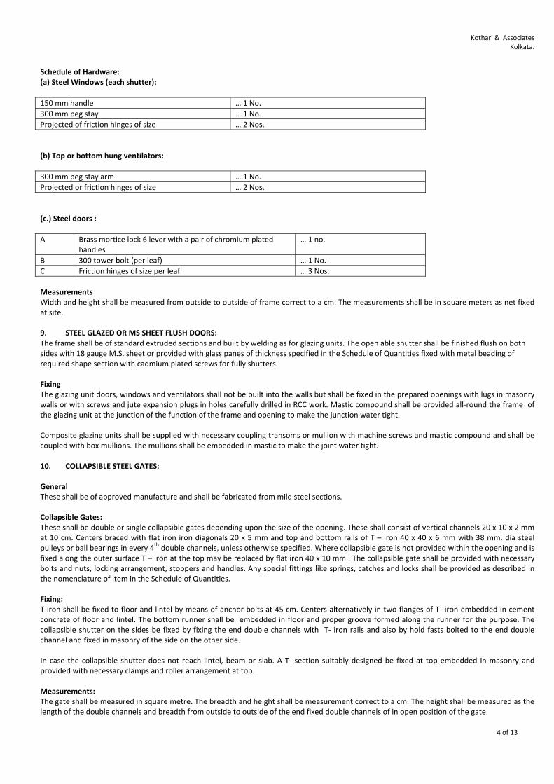
Kothari & Associates Kolkata.
4 of 13
Schedule of Hardware: (a) Steel Windows (each shutter):
150 mm handle … 1 No.
300 mm peg stay … 1 No.
Projected of friction hinges of size … 2 Nos.
(b) Top or bottom hung ventilators:
300 mm peg stay arm … 1 No.
Projected or friction hinges of size … 2 Nos.
(c.) Steel doors :
A Brass mortice lock 6 lever with a pair of chromium plated handles
… 1 no.
B 300 tower bolt (per leaf) … 1 No.
C Friction hinges of size per leaf … 3 Nos.
Measurements Width and height shall be measured from outside to outside of frame correct to a cm. The measurements shall be in square meters as net fixed at site. 9. STEEL GLAZED OR MS SHEET FLUSH DOORS: The frame shall be of standard extruded sections and built by welding as for glazing units. The open able shutter shall be finished flush on both sides with 18 gauge M.S. sheet or provided with glass panes of thickness specified in the Schedule of Quantities fixed with metal beading of required shape section with cadmium plated screws for fully shutters. Fixing The glazing unit doors, windows and ventilators shall not be built into the walls but shall be fixed in the prepared openings with lugs in masonry walls or with screws and jute expansion plugs in holes carefully drilled in RCC work. Mastic compound shall be provided all‐round the frame of the glazing unit at the junction of the function of the frame and opening to make the junction water tight. Composite glazing units shall be supplied with necessary coupling transoms or mullion with machine screws and mastic compound and shall be coupled with box mullions. The mullions shall be embedded in mastic to make the joint water tight. 10. COLLAPSIBLE STEEL GATES: General These shall be of approved manufacture and shall be fabricated from mild steel sections. Collapsible Gates: These shall be double or single collapsible gates depending upon the size of the opening. These shall consist of vertical channels 20 x 10 x 2 mm at 10 cm. Centers braced with flat iron iron diagonals 20 x 5 mm and top and bottom rails of T – iron 40 x 40 x 6 mm with 38 mm. dia steel pulleys or ball bearings in every 4
th double channels, unless otherwise specified. Where collapsible gate is not provided within the opening and is fixed along the outer surface T – iron at the top may be replaced by flat iron 40 x 10 mm . The collapsible gate shall be provided with necessary bolts and nuts, locking arrangement, stoppers and handles. Any special fittings like springs, catches and locks shall be provided as described in the nomenclature of item in the Schedule of Quantities. Fixing: T‐iron shall be fixed to floor and lintel by means of anchor bolts at 45 cm. Centers alternatively in two flanges of T‐ iron embedded in cement concrete of floor and lintel. The bottom runner shall be embedded in floor and proper groove formed along the runner for the purpose. The collapsible shutter on the sides be fixed by fixing the end double channels with T‐ iron rails and also by hold fasts bolted to the end double channel and fixed in masonry of the side on the other side. In case the collapsible shutter does not reach lintel, beam or slab. A T‐ section suitably designed be fixed at top embedded in masonry and provided with necessary clamps and roller arrangement at top. Measurements: The gate shall be measured in square metre. The breadth and height shall be measurement correct to a cm. The height shall be measured as the length of the double channels and breadth from outside to outside of the end fixed double channels of in open position of the gate.

Kothari & Associates Kolkata.
5 of 13
11. ROLLING SHUTTERS: Rolling shutters Shall be of approved manufacture suitable for fixing in the position ordered i.e. outside, inside on or below lintel or between jambs. Shutter up to 12 SqM in area shall be manually operated of Push‐ Up type while bigger size shall be of Reduction Gear type Mechanical Operated by Handles. Laths shall be of 18 gauge best quality mild steel interlocking at 75 mm rolling centre, machine rolled and straightened with an effective bridge depth of 16 mm. Side guides and bottom rail shall be built up mild rolled section. The spring assembly shall be supported on strong mild steel or malleable cast iron brackets shaped to fit the lintel. The rolling springs shall be from tested unbreakable high tensile steel wire or strip of adequate strength to balance the shutter in all position. The shutter shall be complete with door suspension shafts, locking the shutter in all position. The shutter shall complete with door suspension shafts, locking arrangements pulling hooks, handles and other accessories. Measurements: The rolling shutter shall be measured net as fixed at site including portions going in the guides and in the hood up to shafts in square meter width and height shall be measured correct to a cm. 12. FLOOR FINISHING: General: Cement concrete flooring shall in general conform to IS:2571. Cement concrete flooring shall consist of a sub base (laid on the compacted earth or sand fill in case of ground floor only) a base course laid on the sub – base and then finishing layer of floor finishing. In case of ground floor, the filled and compacted bed on which the sub – base is to be laid, shall be as per structural drawings and specifications. The bed for flooring shall be prepared either level or sloped as per drawings and as instructed by Engineer – in – Charge / Architect. Sub – Base: The sub‐base which shall be laid on the prepared bed shall be of specified thickness and as per structural drawings and specifications. The sub – base shall be of gravel/broken bricks/stone aggregate/sand/cement concrete as per drawings and Schedule of Quantities. In case of upper floors, the structural RCC slab shall be treated as sub – base. Base Course: Base course shall be 25 mm thick M‐15 Grade concrete and shall generally conform to civil structural specification. The floor space on which base course is to be laid shall be divided into square / rectangular or as per designed panels to prevent cracks in the floor finish. No dimension of the panels shall exceed 2M and length of the panel shall not exceed 1.5 times its breadth. Base course shall be laid on alternate panels. The borders of the panels shall have mitred joints at the corners of the room and intermediate joints shall be in straight line with panel joints. The panels shall be bound by glass / PVC / stainless steel strips etc. as specified in Schedule of Quantities. These shall be fixed in position with their top at proper level, giving slope wherever required. The flooring shall butt against masonry of wall which shall not be plastered. When the base course is to be laid on hardened base, the sub – base shall be roughened by steel wire brushing and cleaned. Before laying the base course, neat cement slurry @ 2.75 kg of cement per SqM of area shall be brushed into the prepared sub base surface. Cement concrete shall be placed in position and beaten with trowel and finished smooth. Beating shall cease as soon as surface is found covered with cream of mortar. Necessary slope shall be provided. Floor Finishing: Finishing of the surface shall follow immediately after the completion of base course. The base course shall be free of excessive moisture before starting the floor finishing. Use of dry cement, cement sand mixture sprinkled on the surface to stiffen the concrete or absorb excessive moisture shall not permitted. While the concrete is still green, cement @ 2.75 kg per SqM of floor area shall be mixed with water to form a thick slurry and spread over the surface. It shall be pressed twice by means of iron floats, once when the slurry is applied and second time when the cement starts setting. The junction of floor with wall plaster, cladding, skirting shall be rounded off uniformly up to a radius of 25 mm unless otherwise mentioned. Curing: Each finished portion of floor, on completion shall be kept wet with ponding for a minimum period of 7 days. 13. CEMENT CONCRETE GRANOLITHIC FLOORING General: Cement concrete granolithic shall consist of a sub – base, a base course and finishing layer of floor finish. Workmanship shall in general be same as for cement flooring, unless otherwise mentioned.

Kothari & Associates Kolkata.
6 of 13
Workmanship: Workmanship shall in general conform to IS:5491. Sub – Base: The sub – base which shall be laid on the prepared bed shall be of specified thickness and as per structural drawings and specifications. The sub – base shall be of boulders/gravel/broken bricks/sand/cement concrete as per drawings. In case of upper floors, the structural RCC slab shall be treated as sub – base. Base Course (Under Layer): Base course shall be M‐15 grade Concrete and shall generally conform to Civil Structural specification. The floor space on which base course is to be laid shall be divided into square/rectangular or as per designed panels to prevent cracks in the floor finish. No dimension of the panels shall exceed 2M and length of the panel shall not exceed 1.5 times its breadth. Base course shall be laid on alternate panels. The borders of the panels shall have mitred joints at the corners of the room and intermediate joints shall be in straight line with panel joints. The panels shall be bound by glass / PVC / Stainless steel strips etc. as specified in Schedule of Quantities. These shall be fixed in position with their top at proper level, giving slope wherever required. The flooring shall butt against masonry of wall which shall not be plastered. When the base course is to be laid on hardened base, the sub – base shall be roughened by steel wire brushing and cleaned. Before laying the base course, neat cement slurry @ 2.75 kg of cement per SqM of area shall be brushed into the prepared sub – base surface. Cement concrete shall be placed in position and beaten with trowel and finished smooth. Beating shall cease as soon as surface is found covered with cream of mortar. Necessary slope shall be provided. Thickness of base course shall be as follows doe different thickness of floorings:
A 40 mm thick flooring 25 mm thick
B 50 mm thick flooring 35 mm thick
Wearing Top Layer: The top layer shall be laid over first layer within 15 minutes of laying the first layer. The cement and aggregates for the top layer shall be mixed dry. After mixing, sufficient quantity of washed sand and water shall be added to make the mix plastic but not flowing. The top and bottom layer shall firmly grip together. Floor Finishing: Finishing of the surface shall follow immediately after the completion of base course. The base course shall be free of excessive moisture before starting the floor finishing. Use of dry cement, cement sand mixture sprinkled on the surface to stiffen the concrete or absorb excessive moisture shall not be permitted. While the concrete is still green, cement @ 2.75 kg per Sq.M. of floor area shall be mixed with water to form a thick slurry and spread over the surface. It shall be pressed twice by means of iron floats, once when the slurry is applied and second time when the cement starts setting. The junction of floor with wall plaster, cladding, skirting shall be rounded off uniformly up to a radius of 25 mm unless otherwise mentioned. Curing: Each finished portion of floor, on completion shall be kept wet with ponding for a minimum period of 7 days. 14. HEAVY DUTY FLOORING: General: Heavy duty flooring shall consist of a sub – base, a base course and a finishing layer of floor finish. Sub – Base: The sub – base which shall be laid on the prepared bed shall be of specified thickness and as per structural drawings and specifications. The sub – base shall be of boulders / Gravel / Broken bricks / sand cement concrete as per drawings. In case of upper floors, the structural RCC slab shall be treated as sub – base. Base Course: Base course shall consist of one layer of 35 mm thick cement concrete (1 cement : 1.5 Coarse sand : 3.5 stone aggregates of 10 mm to 6 mm size by volume) laid on sub – base in panels.

Kothari & Associates Kolkata.
7 of 13
Floor Finish: Finishing layer shall be of cement, hardener and stone aggregate mix of 15 mm thickness laid over the base course. Unless otherwise mentioned, one part of approved quality hardener and four parts of cement by weight shall be mixed dry. This dry mixture shall be mixed with stone grit of 6 mm and down size in the ratio of 1 hardener and cement mixture : 2 stone grit by volume. Just enough water shall then be added to the mix. The mixture so obtained shall then be laid on the base course within 2 to 4 hours of latter’s laying. It shall be firmly pressed into bottom concrete so as to have a good bond with it. After the starting of initial setting, the surface shall be finished smooth and true with steel floats. 15. PRECAST HYDRAULICALLY PRESSED CEMENT TILES: Cement mortar shall be in accordance with civil structural specification and following Schedule:
A For Flooring 20 mm thick, cement mortar (1 cement : 6 coarse sand by volume)
B For Skirting / Dado / Riser 12 mm thick, cement mortar (1 cement : 3 coarse sand by volume)
Workmanship: Workmanship shall in general conform to IS: 1443. The base on which tiles are to be laid shall be cleaned of all dust, dirt and properly wetted by applying neat cement slurry @ 2.75 kg. of cement per SqM of area without allowing water pools. Cement mortar of specified thickness shall then be spread over the base for two rows of tiles and 3‐5 metres in length. The mortar shall be laid in slope as per requirements and thickness of mortar shall not be less than 10 mm at any place. The top of the mortar shall be kept rough so that cement slurry can be absorbed. Laying shall be from centre and proceed outwards in two directions at 90
o. Cut tiles of uniform sizes shall be laid along periphery, if necessary. Neat cement slurry @ 4.4 kg. Of cement per SqM shall be spread over the mortar bed for laying 20 tiles at a time. The tiles shall then be fixed in this grout one after the other, each tile being gently tapped and properly bedded in line and level. The joints shall not exceed 1.5 mm in width. After the day’s work, the excess cement slurry on top and the joints shall be cleaned with broom stick and washed before the slurry sets hard. Next day, the joints shall be filled with the cement grout to match the shade of the tile. Tiles along the periphery shall be continued by average 12 mm under the wall plaster. Skirting or dado. For skirting / dado / risers on the brick masonry wall, the joints shall be raked out to a depth of at least 15 mm while the masonry is being laid. In case of concrete work, the surface shall be hauled and roughened with wire brushes. The wall surface shall be uniformly and evenly covered with backing of cement mortar 1:3 (1 cement : 3 coarse sand by volume) of specified thickness. Before hardening of the cushioning mortar, back of each tile shall be covered with a neat layer of cement slurry @ 4.4 kg of cement per SqM and edges with white cement with or without pigment to match the shade of tiles and the tiles then shall be pressed on the backing and tapped. The tiles shall be corrected to proper planes with joints truly vertical in required pattern and butt jointed. The fixing shall be done from bottom upward. The top of skirting and dado shall be truly horizontal. Curing: The flooring shall be cured for 7 days by keeping it wet with ponding. Heavy traffic on the flooring shall be permitted only after 14 days. Grinding and Polishing: Grinding shall be commenced after 14 days when the tiles and the joints are properly set. Grinding shall be done by machines except for skirting and small areas. First grinding shall be done with carborundum stones of 48 to 60 grade grit fitted in the machine. Water shall be properly used during grinding. When the chips show up and the floor has been uniformly rubbed, it shall be cleaned with water baring all pin – holes. It shall then be covered with a thin coat of grey / white cement mixed with pigments to match with colour of the flooring. This grout shall be kept moist for a week. Thereafter the second grinding shall be started with carborundum stone of 120 grit. Grinding and curing shall follow again. Final grinding shall be with carborundum of Grade 220 to 350 grit using water in abundance. The floor shall be washed clean with water, oxalic acid powder shall then be dusted at 35 gms/SqM. On the surface rubbed with machine fitted hessian bobs or rubbed hard with woolen rags. The floor shall then be washed clean and dried with a soft cloth or linen. If any tile is disturbed or damaged, it shall be refitted or replaced and properly jointed and polished. 16. CEMENT PLASTER SKIRTING: Materials: Cement plaster skirting shall be laid with cement mortar (1 cement : 3 coarse sand by volume) and shall be of specified thickness (6 mm / 12 m / 18 mm) as per Item description. Workmanship: The surface on which the skirting is to be applied shall be prepared and skirting of specified thickness shall be laid. The junction between flooring and wall shall be rounded off to a radius of 25 mm if not otherwise mentioned. While the mortar is still green, cement @ 2.75 kg per square metre shall be mixed with water to form a thick slurry and applied over the mortar. It shall be pressed twice by means of iron floats, once when the slurry is applied and second time when the cement starts setting.

Kothari & Associates Kolkata.
8 of 13
17. CAST ‐ IN ‐ SITU TERRAZZO FINISH: Base Course (Under layer) Base course for cast – in – situ terrazzo flooring shall be 25 mm thick cement concrete (1 cement : 2 coarse sand : 4 stone aggregate, 10 mm nominal size by volume). In case of vertical surfaces, the base course shall be 13 mm thick cement mortar (1 cement : 3 coarse sand by volume) Aggregates for Terrazzo Topping: The aggregate to be used in topping shall be marble chips pf plain White / Pink Makrana / Baroda green etc. all Grade – 1 As specified which shall be of 10 mm nominal size. Marble powder to be used in terrazzo topping shall pass through IS Sieve Terrazzo. Marble chips shall be hard, sound, dense and homogenous in texture with crystalline and coarse grains. It shall be uniform in colour and free from stains, cracks, decay and weathering. All proportions of materials used should be as directed by the Engineer – in – Charge / as specified. Pigments: Pigments to be used in terrazzo shall be of permanent colour and shall conform to IS:2114 , Table – 1. Workmanship: Workmanship shall in general conform to IS: 2114. Terrazzo flooring shall be of specified thickness and shall be laid in two layers and in panels. Under layer or base course shall be of cement concrete laid over sub base and top layer shall be of terrazzo floor finish. Details of panels shall as per drawings. The thickness of terrazzo finish shall be 15 mm. Top layer shall consist of mix of white cement, marble powder, marble chips, water and pigments. Cement and marble powder mix powder mix proportion shall be 3:1 by weight. Cement, marble powder mix shall be mixed with marble chips in the proportion of 4:7 by volume. Quality and shade of chips and powder shall be as specified with a view to avoid variation in colour. Sufficient quantity of white cement shall be added in the cement mix to obtain the desired shade. Mixing shall be done in a trough or tub and complete quantities of white cement and pigment for a particular unit of job shall be dry mixed with aggregates. Water shall be added in small quantities to this dry mix to get a proper consistency. The mix shall be plastic but not so wet as to flow. The mix shall be used within 30 minutes of its preparation. The base course / under layer shall be divided in panels with dividing strips (glass / PVC / Stainless steel strips) up to the finished surface levels. The sub‐base shall be cleaned of all dust, dirt or any loose material. It shall then be wetted with water, mopped and smeared with neat cement slurry. Terrazzo topping shall be laid while the under layer is still plastic but has hardened enough which is normally achieved between 18 – 24 hours after laying the under layer. A cement slurry @ 2.75 kg of cement per SqM of area pigmented with the same colour as the topping be brushed on the surface immediately before laying the topping. The terrazzo mix shall be laid to a uniform thickness and be compacted thoroughly by tamping or rolling and trowelled and brought true to required lavel by a straight edge and steel floats so that the maximum amount of marble chips come up and spreaded uniformly over the surface and no part of the surface is left without the chips. Curing: The surface shall be left dry for air curing for a period of 12 – 18 hours. Thereafter water shall be allowed to stand overnight in pools for a period of minimum four days. Grinding and Finishing: Grinding and polishing shall be done with machines and shall start after 7 days of laying. First grinding shall be done with carborundum stone of 60 grit size. The surface shall than be washed clean and grout of cement and / or colouring matter in same mix and proportion as the topping in order to fill any pin holes that appear. It shall then be allowed to dry for 24 hours and wet cured. The second grinding shall be done with carborundum stone of grit size. The surface shall then be prepared as after first grinding. The third grinding shall be done with carborundum stone of 120 to 150 grit size. The surface shall then be prepared again as after first grinding. The fourth grinding shall be done with carborundum stone of 320 to 400 grit size. The surface shall then be washed clean and rubbed hard with felt and slightly moistened oxalic acid powder @ 35 gms per square metre of less surface. After the finishing works are over, the surface shall be washed with dilute oxalic add solution and dried. Floor polishing machine fitted with felt on hessian bobs shall then be run over it until the floor shines. In case of polishing, wax polish shall be applied on the surface with the help of soft linen over a clean and dry surface. Then the polishing machine fitted with bobs shall be run over it. Clean saw dust shall be spread over the floor surface and polishing machine again operated to remove excess wax. Cast – in – situ Terrazzo in skirting, dado and risers shall be of specified thickness and of same shade as that of the flooring. Under layer for terrazzo on vertical surfaces shall be of stiff cement mortar 1:3 ( 1 cement : 3 coarse sand by volume) finished rough so as to give a good bond to the topping. Terrazzo topping shall be average 12 mm thick and under layer shall be 13 mm thick. Terrazzo topping shall be laid on the under layer. Other details shall be same as for flooring excepting grinding which shall be manual and panels dividers are required.

Kothari & Associates Kolkata.
9 of 13
18. PRECAST HYDRAULICALLY PRESSED TERRAZZO TILES: Cement Mortar: Cement mortar shall be in accordance with civil structural specification and following schedule.
A For Flooring 20 mm thick, cement mortar (1 cement : 4 coarse sand by volume)
B For Skirting / Dado / Riser 12 mm thick, cement mortar (1 cement : 3 coarse sand by volume)
Workmanship: Workmanship shall in general conform to IS: 1443. the base on which tiles are to be laid shall be cleaned of all dust, dirt and properly wetted by applying neat cement slurry @ 2.75 kg of cement per Sq.M. of area without allowing water pools. Cement mortar of specified thickness shall then be spread over the base for two rows of tiles and 3‐5 metres in length. The mortar shall be laid in slope as per requirements and thickness of mortar shall not be less than 10 mm at any place. The top of the mortar shall be kept rough so that cement slurry can be absorbed. laying shall be from centre and proceed outwards in two directions at 90o. Cut tiles of uniform sizes shall be laid along periphery, if necessary. Neat cement slurry @ 4.4 kg of cement per Sq.M. shall be spread over the mortar bed for laying 20 tiles at a time. The tiles then be fixed in this grout one after the other, each tile being gently tapped and properly bedded in line and level. The joints shall not exceed 1.5mm in width. After ths day’s work, the excess cement slurry on top and the joints shall be cleaned with broom stick and washed before the slurry sets hard. Next day, the joints shall be filled with the cement grout to match the shade of the tile. Tiles along the periphery shall be continued by average 12 mm under the wall plaster, skirting or dado. For skirting / dado / risers on the bricks masonry wall, the joints shall be raked out to a depth of at least 15 mm while the masonry is being laid. In case of concrete work, the surface shall be hauled and roughened with wire brushes. The wall surface shall be uniformly and evenly covered with backing of cement mortar 1:3 (1 cement : 3 coarse sand by volume) of specified thickness. Before hardening of the cushioning mortar, back of each tile shall be covered with a neat layer slurry @ 4.4 kg of cement per SqM and edges with white cement with or without pigment to match the shade of tiles and the tiles then shall be pressed on the backing and tapped. The tiles shall be corrected to proper planes with joints truly vertical in required pattern and butt jointed. The fixing shall be done from bottom upward. The top of skirting and dado shall be truly horizontal. Curing: The flooring shall be cured for 7 days by keeping it wet with ponding. Heavy traffic on the flooring shall be permitted only after 14 days. Grinding and Polishing: Grinding shall be commenced after 14 days when the tiles and the joints are properly set. Grinding shall be done by machines except for skirting and small areas. First grinding shall be done with carborundum stones of 48 to 60 grade grit fitted in the machine. Water shall be properly used during grinding. When the chips show up and the floor has been uniformly rubbed, it shall be cleaned with water baring all pin – holes. It shall then be covered with a thin coat of grey / white cement mixed with pigments to match with colour of the flooring. This grout shall be kept moist for a week. Thereafter the second grinding shall be started with carborundum stone of 120 grit. Grinding and curing shall follow again. Final grinding shall be with carborundum of Grade 220 to 350 grit using water in abundance. The floor shall be washed clean with water, oxalic acid powder shall then be dusted at 35 gms/SqM on the surface rubbed with machine fitted hessian bobs or rubbed hard with woolen rags. The floor shall then be washed clean and dried with a soft cloth or linen. If any tile is disturbed or damaged, it shall be refitted or replaced and properly jointed and polished. 19. TILE WORK: Tiles: Glazed (vitreous and ceramic tiles shall conform to IS:777 and shall be of specified shade, size and of approved manufacturer. Ceramic tiles shall be matt finished and non slip type. The size shall be as per follows:
a. White / Coloured glazed vitreous tiles 200 mm x 100 mm x 6 mm 200 mm x 150 mm x 6 mm 200 mm x 300 mm x 6 mm 300 mm x 300 mm x 8 mm (+ 5%)
b. Ceramic Tiles 300 mm x 300 mm x 8 mm (+ 5%) 200 mm x 100 mm x 6 mm
Pigments: Pigments to be admixed with mortar or for grouting the joints shall conform to IS:2114. Cement mortar shall be in accordance with civil structural specification and following Schedule.
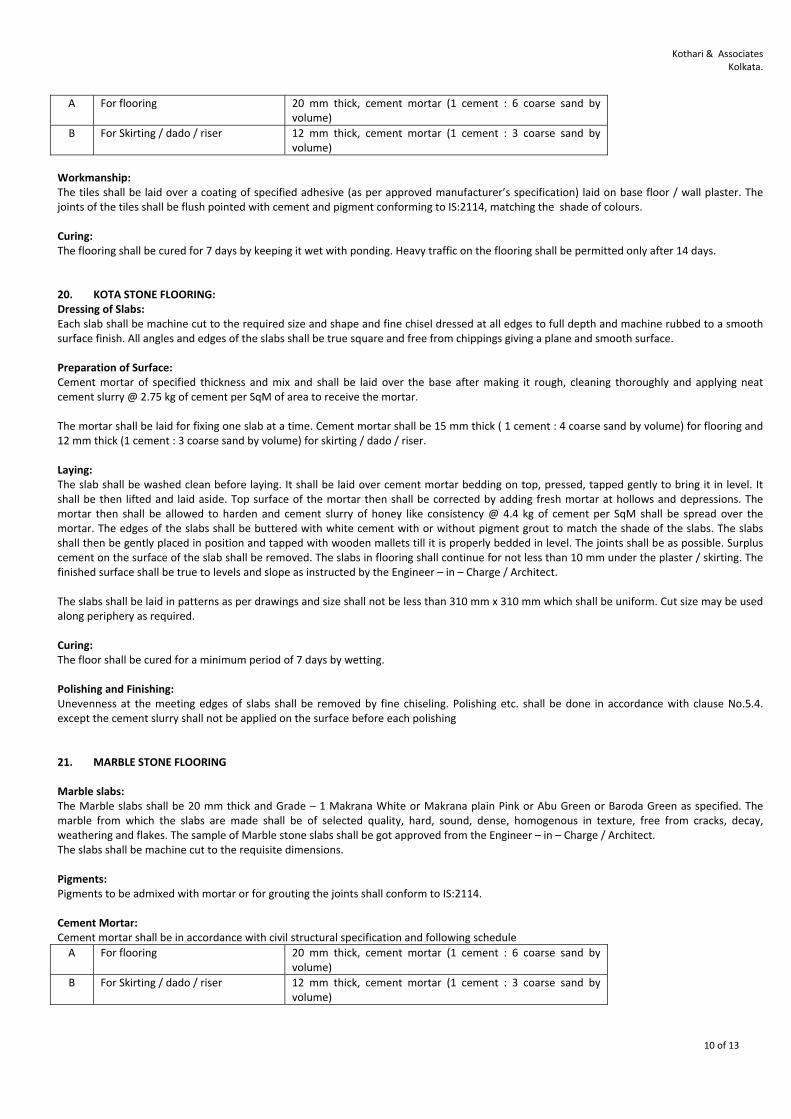
Kothari & Associates Kolkata.
10 of 13
A For flooring 20 mm thick, cement mortar (1 cement : 6 coarse sand by volume)
B For Skirting / dado / riser 12 mm thick, cement mortar (1 cement : 3 coarse sand by volume)
Workmanship: The tiles shall be laid over a coating of specified adhesive (as per approved manufacturer’s specification) laid on base floor / wall plaster. The joints of the tiles shall be flush pointed with cement and pigment conforming to IS:2114, matching the shade of colours. Curing: The flooring shall be cured for 7 days by keeping it wet with ponding. Heavy traffic on the flooring shall be permitted only after 14 days. 20. KOTA STONE FLOORING: Dressing of Slabs: Each slab shall be machine cut to the required size and shape and fine chisel dressed at all edges to full depth and machine rubbed to a smooth surface finish. All angles and edges of the slabs shall be true square and free from chippings giving a plane and smooth surface. Preparation of Surface: Cement mortar of specified thickness and mix and shall be laid over the base after making it rough, cleaning thoroughly and applying neat cement slurry @ 2.75 kg of cement per SqM of area to receive the mortar. The mortar shall be laid for fixing one slab at a time. Cement mortar shall be 15 mm thick ( 1 cement : 4 coarse sand by volume) for flooring and 12 mm thick (1 cement : 3 coarse sand by volume) for skirting / dado / riser. Laying: The slab shall be washed clean before laying. It shall be laid over cement mortar bedding on top, pressed, tapped gently to bring it in level. It shall be then lifted and laid aside. Top surface of the mortar then shall be corrected by adding fresh mortar at hollows and depressions. The mortar then shall be allowed to harden and cement slurry of honey like consistency @ 4.4 kg of cement per SqM shall be spread over the mortar. The edges of the slabs shall be buttered with white cement with or without pigment grout to match the shade of the slabs. The slabs shall then be gently placed in position and tapped with wooden mallets till it is properly bedded in level. The joints shall be as possible. Surplus cement on the surface of the slab shall be removed. The slabs in flooring shall continue for not less than 10 mm under the plaster / skirting. The finished surface shall be true to levels and slope as instructed by the Engineer – in – Charge / Architect. The slabs shall be laid in patterns as per drawings and size shall not be less than 310 mm x 310 mm which shall be uniform. Cut size may be used along periphery as required. Curing: The floor shall be cured for a minimum period of 7 days by wetting. Polishing and Finishing: Unevenness at the meeting edges of slabs shall be removed by fine chiseling. Polishing etc. shall be done in accordance with clause No.5.4. except the cement slurry shall not be applied on the surface before each polishing 21. MARBLE STONE FLOORING Marble slabs: The Marble slabs shall be 20 mm thick and Grade – 1 Makrana White or Makrana plain Pink or Abu Green or Baroda Green as specified. The marble from which the slabs are made shall be of selected quality, hard, sound, dense, homogenous in texture, free from cracks, decay, weathering and flakes. The sample of Marble stone slabs shall be got approved from the Engineer – in – Charge / Architect. The slabs shall be machine cut to the requisite dimensions. Pigments: Pigments to be admixed with mortar or for grouting the joints shall conform to IS:2114. Cement Mortar: Cement mortar shall be in accordance with civil structural specification and following schedule
A For flooring 20 mm thick, cement mortar (1 cement : 6 coarse sand by volume)
B For Skirting / dado / riser 12 mm thick, cement mortar (1 cement : 3 coarse sand by volume)

Kothari & Associates Kolkata.
11 of 13
Workmanship: Same as Kota stone except that cement mortar shall be 20 mm thick (1 cement : 6 coarse sand by volume) for flooring. Curing: The floor shall be cured for a minimum period of 7 days by wetting. Polishing and Finishing: Unevenness at the meeting edges of slabs shall be removed by fine chiseling. Polishing etc. shall be done in accordance with Clause No.5.4. except that cement slurry shall not be applied on the surface before each polishing. 22. WHITE WASHING, COLOUR WASHING: Materials: Lime of CLASS‐C (Fat lime) shall be used for White Washing / Colour Washing. Preparation of surface: All surfaces for white washing, colour washing, painting shall be thoroughly brushed free from mortar droppings and foreign matter and prepared to satisfaction of the Engineer‐in‐charge / Architect before application of treatment. Before white washing all the nails etc have to be removed from the walls and all nail or other holes, small depressions or damages in plaster of wall surface shall be filled or repaired to the original condition with lime paste. Old surfaces spoiled by smoke and greasy shoots shall be sprinkled with surki and water and to be rubbed with brick bats or steel wire brushes or steel scrappers. The surface shall then be broomed to remove all dust and shall be washed with clean water. Preparation of White Wash: The White Washing is to be done with 5 parts of stone lime and one part of shell lime with necessary gum (2 Kgs per CuM of lime) using indigo as necessary and to be mixed as per standard practice. Procedure and preparation of the surface shall be same as in white washing. Application of White Wash & Colour Wash: The operation for each coat shall consist of four consecutive strokes of the brush, one horizontally from right to left and the next from left to right and the third from bottom to upward and the from top to downward before the previous stroke dries. Each coat shall be allowed to dry before the next coat applied. No portion of the surface shall be left out initially to be patched up later on. The brush shall be dipped in white wash or colour wash, pressed lightly against the wall of the container and then applied by lightly pressing against the surface with full swing of hand. The white wash on ceiling should be done prior to that on walls. Protective Measures: Surfaces of doors, windows, floors, articles of furniture, beams etc and such other parts of the building not to be white or colour washed shall be protected from being splashed upon. Such surfaces shall be cleaned of white or colour wash splashes, if any. 23. DRY DISTEMPERING: Dry distempering of approved brand and manufacturer shall be used. The shade shall be got approved from the Engineer‐in‐charge / Architect before application. The Dry distemper shall be stirred slowly in clean water using 6 deciliters of water per kg of distemper or as specified by the manufacturer. Warm water shall preferably used. It shall be allowed to stand for 30 minutes. The mixture shall be well stirred before and during use to maintain an even consistency. Distemper shall not be mixed in larger quantity than is actually required for one day’s work. All surfaces for distempering shall be thoroughly brushed free from mortar droppings and foreign matter and prepared to satisfaction of the Engineer‐in‐charge / Architect before application of treatment. Pitting in plaster shall be made good with plaster of paris mixed with dry distemper of the colour to be used. The surface shall be rubbed down again with a fine grade sand paper and made smooth. A coat of distemper shall be applied over the patches. The surface shall be allowed to dry thoroughly before the regular coat is applied. A priming coat of whiting (ground white chalk) shall be applied and no white washing coat shall be used as a priming coat of distemper. 24. PAINTING: All surfaces for painting shall be properly sand papered and cleaned and where necessary good quality putty shall be used to hide all holes, cracks, open joints etc. The rate for painting includes such work. Paint shall be applied with approved brushes and surfaces shall be sand papered after every coat. All work when completed shall present a smooth, clean solid and uniform surface, to the satisfaction of the Engineer‐in‐charge. (a ) Primer : All surfaces for painting, if they are new, should have a coat of priming before application of the paint. Old surfaces where existing paints have been completely worn out owing to long use should owing to long use should also receive a coat of priming before application of fresh painting. ( i ) Wood Primer : Wood primer of approved brand and manufacture is to be applied on the wooden surface which would be free from moisture and loose particles.

Kothari & Associates Kolkata.
12 of 13
(ii) Steel Primer: For steel surface red oxide primer, zinc chromate primer of approved brand and manufacture and as per direction of the Engineer‐ in‐Charge is to be applied on the surface. The surface should be made free of grease, rust, moisture and loose particles. (iii) Acrylic Primer Coat (solvent based Primer) : Acrylic primer coat is to be used as base coat on wall finish of cement, lime or lime
cement plaster surface before application of any wall coating e.g. distemper, oil based paints, synthetic enamel, acrylic emulsion etc .on them. Priming coat shall be preferably applied by brushing and not by spraying. Hurried priming shall be avoided particularly on absorbent surface New plaster patches in old work before applying distemper Paris etc. should also be treated with acrylic primer. The surface shall then be allowed to dry for at least 48 hours. It shall then be sand papered to give a smooth and even surface. Any unevenness shall be made good by applying putty, made of plaster of Paris mixed with water on the entire surface including filling up the undulation and the sand papering the same after it is dry. The cement primer shall be applied with a brush on the clean dry and smooth surface Horizontal strokes shall be given first, vertical strokes shall be applied immediately afterwards. The entire operation will constitute one coat. The surface shall be finished as uniformly as possible leaving no brush marks. It shall be allowed to dry for at least 48 hours before oil bound distemper or paint is applied.
(b) Synthetic Enamel Paint : Synthetic enamel paint of approved brand and manufacture and of the require shade shall be used for the top
coat and an undercoat of shade to match the coat as recommended by the manufacturer shall be used. Undercoat of the specified paints of shade suited to the shade of the top coat shall be applied and allowed to dry overnight. It shall be rubbed next day with the fine grade of wet abrasive paper to ensure a smooth and eve surface free from brush marks and all loose particles dusted off. Top coats of specified paint of the desired shade shall be applied after the undercoat is thoroughly dry. Additional finishing coats shall be applied if found necessary to ensure properly uniform glossy surface.
( c ) Aluminium Paint : Aluminium paint of approved brand and manufacture shall be used. The paint comes compact dual containers with the
paste and the medium separately. The two shall be mixed together to proper consistency before use. Each coat shall be allowed to dry for 24 hours and lightly rubbed down with fine grade sand paper and dusted before the next coat is applied. The finished surface shall present an even and uniform appearance. As aluminium paint is likely to settle in the container, care shall be taken to frequently stir paint during use. Also the paint shall be applied and laid off quickly, as surface is otherwise not easily finished.
(d) Interior Acrylic Emulsion Paint : Acrylic emulsion paint are not suitable for application on external surface and surface which are liable to heavy condensation and are be used generally on internal surface. For plastered surfaces a cement priming coat is required before application of acrylic emulsion. Acrylic emulsion paint of approved brand and manufacture and of the required shade shall be used. The paint will be applied in the usual manner with brush or roller .The paint dries by evaporation of the water content and as soon as the water has evaporated the film gets hard and the next coat can be applied. The time for drying various from one hour on absorbent surfaces to 2 to 3 hours on non‐absorbent surfaces. The thinning of emulsion Is t o be done with water and not with turpentine. Thinning with water will be particularly required for the undercoat t which is applied on the absorbent surface. The quantity of thinner to be added shall be as per manufacturer’s instructions. The surface on finishing shall present a flat, velvety, smooth finish. If necessary more coats will be applied till the surface present a uniform appearance. Precautions : ( i ) Old brushes if they are to be used with emulsion paints should be completely dried of turpentine or oil paints by washing in warm soap water. Brushes should be quickly washed in water, immediately after use and kept immersed in water during break periods to prevent the paint from hardening on the brush.
(ii) In the preparation of walls f or Acrylic emulsion painting, an oil base putty shall used in filling cracks, holes etc. (iii) Splashes in floor etc. shall be cleaned out without delay as they will be difficult remove after hardening. (iv) Washing of surface treated emulsion paints shall not be done within 3 to 4 weeks of application.
(e) Vernishing : Varnish for the undercoat shall be a flatting varnish of the same manufacture as the top coats. New wood work to be varnished shall be finished smooth with a carpenter’s plane. Knots shall be cut to a slight depth. Cracks and holes shall be cleaned of dust. The knots, cracks etc shall then be filled in with woodputty. The varnish shall be applied liberally with a full brush and spread evenly with short light strokes to avoid frothing. If the work is vertical the varnish shall be crossed and recrossed and then laid off, the later being finished on the upstroke so that varnish, as it sets, flows down and eliminates brush marks. The above process will constitute one coat. If the surface is horizontal, varnish shall be worked in every direction with light quick strokes and finished in one definite direction so that it will set without showing brush marks. Rubbing down and fatting the surface shall be done after each coat except the final coat with fine sand paper. The work shall be allowed to dry away from draughts and damp air .The finished surface shall then present a uniform appearance and fine glossy surface free from streaks, blister etc. Any varnish left over in the small container shall not be poured back into the stock tin, as it will render the latter unfit for use Special fine haired varnishing brush shall be used and not ordinary paint brushes. Brushes shall be well worm and perfectly clean. (f) Oiling with Raw linseed Oil : Raw linseed oil shall be lightly viscous but clear and of a yellowish colour with light brown tinge. Its specific gravity at a temperature of 30
oC shall be between 0.293 and 0.298.The oil shall be mellow and sweet to the taste with very little smell. The oil shall be of sufficiently matured quality. Oil turbid or thick, with acid and bitter taste and rancid odour and which remains sticky fora considerable time shall be rejected. The oil shall be of approved brand and manufacture. The wood work shall be cleaned of al l smoke and water and completely dried. The oil shall be applied freely with brushes (not rags) and spread evenly and smooth until no more oil is absorbed. Each subsequent coat shall be applied after the previous coat is thoroughly dried and in any case not before 24 hours of application of the first coat. Work after completion shall not be patchy and sticky to the touch and shall present a uniform appearance.

Kothari & Associates Kolkata.
13 of 13
(g) Wax polishing : Wax polishing shall be done with material of approved brand and manufacture. Preparation of surface will be same as for varnishing. The polish shall be applied evenly with a clean oft pad of cotton cloth is such a way that the surface is completely and fully covered. The surface is then rubbed continuously for half an hour. When the surface is quite dry, a second coat shall be applied in the same manner and rubbed continuously for one hour or until the surface is dry.The final coat shall then be applied and rubbed for two hours ( more if necessary ) until the surface has assumed a uniform gloss and is dry, showing no sign of stickiness..The final polish depends largely on the amount of rubbing which should be continuous and with uniform pressure with frequently changes in the direction.
(h) French polishing : Pure shellac varying from pale orange to lemon yellow colour, free from resin or dirt shall be dissolved in
methylated spirit at the rate of 150 gm. Of shellac to a litre of spirit. Suitable pigment shall be added to get required shade The surface shall be cleaned. All unevenness shall be rubbed down smooth with sand paper and well dusted. Knots if visible shall be covered with a preparation of red lead and glue size laid on while hot .Holes and indentations on the surface shall be stopped with glaziers putty. The surface shall then be given a coat of wood filler made by mixing whiting (ground chalk) in methylated spirit at the rate of 1.4 kg. of whiting per litre of spirit. The surface shall again be rubbed down perfectly smooth with glass paper and wiped clean. A pad of woolen cloth covered by a fine cloth shall be used to apply the polish. The pad shall be moistened with the polish and rubbed hard on the wood in a series of overlapping circles applying the mixture sparingly but uniformly over the entire area of an even evil surface. A trace of linseed oil on the face of the pad facilities this operation. The surface shall be allowed to dry and the remaining coats applied in the same way. To finish off, the pad shall be covered with a fresh piece of clean fine cotton cloth, slightly damped with methylated spirit and rubbed lightly and quickly with circular motions. The finished surface shall have a uniform texture and high gloss.
‐‐‐‐‐‐‐‐‐‐‐‐‐‐‐‐‐‐‐‐‐‐‐‐‐‐‐‐‐‐‐‐‐