TECHNICAL SPECIFICATIONS - Barnstable
131
COPY NO. REHABILITATION OF MARSTONS MILLS FISHWAY BARNSTABLE, MA TECHNICAL SPECIFICATIONS 13097A June 2016
Transcript of TECHNICAL SPECIFICATIONS - Barnstable

COPY NO.
REHABILITATION OF MARSTONS MILLS FISHWAY
BARNSTABLE, MA
TECHNICAL SPECIFICATIONS
13097A
June 2016

(BARNSTABLE, MA)
BIDDING AND CONTRACT REQUIREMENTS
AND SPECIFICATIONS
FOR
REHABILITATION OF MARSTONS MILLS FISHWAY
Prepared By:
Wright-Pierce
175 Ammon Drive, Suite 208
Manchester NH 03103
Phone: 603-606-4420
June 2016

TC-1 13097A
TABLE OF CONTENTS
SECTION TITLE
DIVISION 0 - BIDDING AND CONTRACT REQUIREMENTS
These specifications are being provided by the Town of Barnstable, Massachusetts.
DIVISION 1 - GENERAL REQUIREMENTS
01010 Summary of Work
01050 Coordination
01150 Measurement and Payment
01310 Construction Schedules
01340 Submittals
01400 Quality Control
01562 Dust Control
01720 Project Record Documents
DIVISION 2 - SITE WORK
02050a Demolition
02110 Clearing and Grubbing
02200 Earthwork
02260 Filter Fabric
02270 Temporary Erosion Control
02401 Cofferdams and Dewatering
02485 Loaming and Seeding
DIVISION 3 - CONCRETE
03300 Cast-in-Place Concrete
03346 Concrete Finishing, Curing and Repairs
03420 Precast Concrete Structures
03421 Precast Concrete Retaining Wall
DIVISION 5 - METALS
05500 Metal Fabrications
DIVISION 6 - WOOD AND PLASTICS
06100 Rough Carpentry
APPENDICES
A WOODEN PEDESTRIAN BRIDGE MANUFACTURER’S DRAWINGS
B SOIL SAMPLES
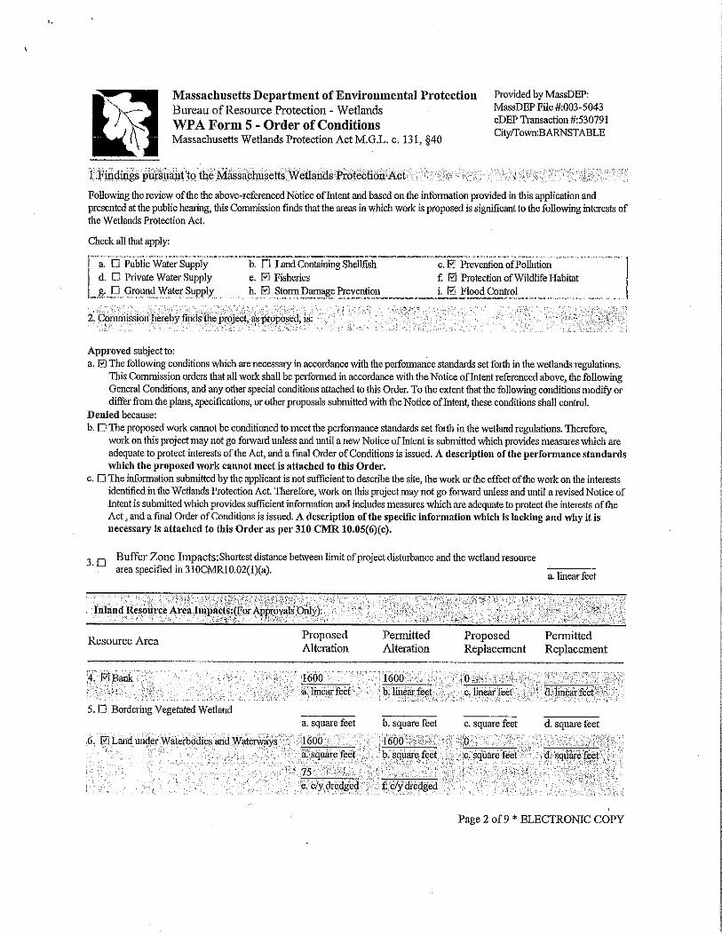
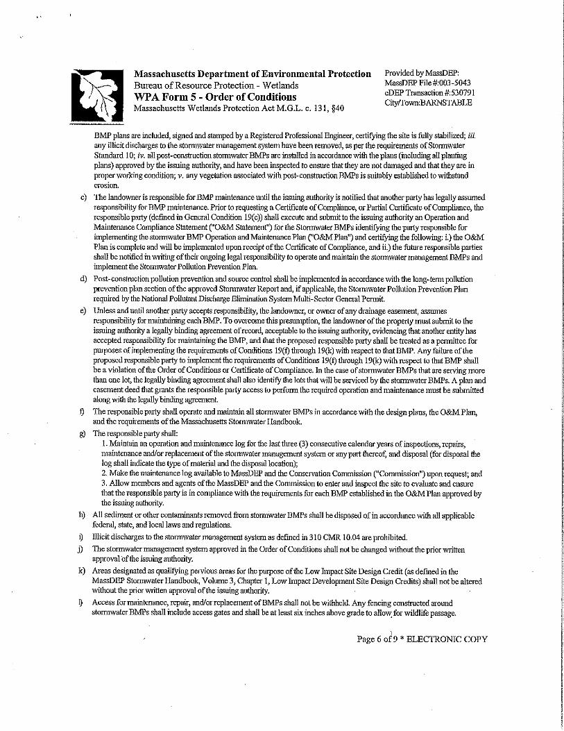
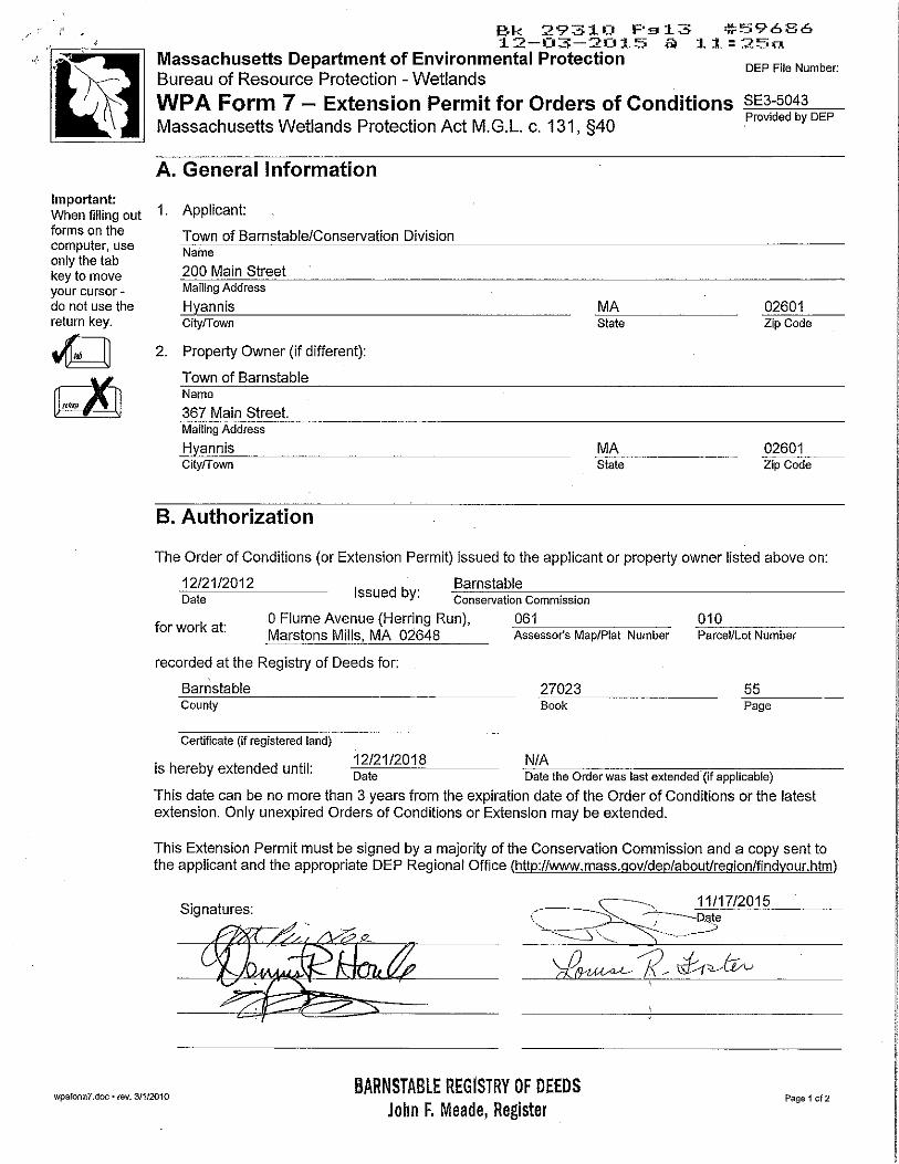
C ORDER OF CONDITIONS
END OF SECTION
13097
01010-1
SECTION 01010A
SUMMARY OF WORK
PART 1 - GENERAL
1.1 DESCRIPTION
A. Work Included
1. The project involves the rehabilitation of the existing Middle Pond Fishway
including partial concrete demolition of the existing fishway exit structure to
accommodate construction of a new concrete fishway and denil ladder,
removal of existing culvert within the fishway, installation of precast
segmental block retaining wall, precast concrete weir cutoff walls, fishway,
denil baffles, connection to existing structures, installation of wooden
pedestrian bridge, and cast-in-place denil extension as noted in the plans and
specifications.. The project will be required to meet specific schedule,
permit requirements and other ecological considerations as defined in permit
conditions.
B. The Related Work Specified Elsewhere:
1. Coordination: Section 01050
2. Construction Schedules: Section 01310.
C. Removals, Relocations and Rearrangements
1. Examine the existing site for the work of all trades which will influence the
cost of the work under the bid. This work shall include removals, relocations
and rearrangements which may interfere with, disturb or complicate the
performance of the work under the bid involving systems, equipment and
related service lines, which shall continue to be utilized as part of the finished
project. The Contractor is responsible for all coordination in this regard.
2. Provide in the bid a sufficient amount to include all removals, relocations,
rearrangements and reconnections herein specified, necessary or required to
provide approved operation and coordination of the combined new and
existing systems and equipment.
D. Restoration of Disturbed Areas
1. The Contractor is responsible for the restoration of all areas
disturbed by the work to an equal or better condition than that
encountered prior to construction.
E. Maintenance of Flows
1. No work shall be conducted during the spring spawning season of
March 1 – June 30, or during any other times where the fish species
are observed attempting to ascend or descend through the fishway.
2. The Contractor will be required to provide and maintain base flow at
all times throughout construction.
2. The contractor will be required to provide and maintain suitable
facilities to allow for downstream passage of juvenile alewife/river
herring at all times. Said facilities shall be subject to the approval of
the Massachusetts Division of Marine Fisheries and engineer.

01010-2
SUMMARY OF WORK
13097
PART 2 - PRODUCTS
Not Applicable.
PART 3 - EXECUTION
3.1 DESCRIPTION
A. As specified on the drawings and as described in the applicable sections of these
specifications.
B. Contractor shall coordinate the schedule for his activities with the Owner until the
project is completed.
PART 4 - SCHEDULE
4.1 LIMITATIONS
A. Working Hours: Construction activities may be conducted from dawn to dusk,
Monday through Friday from 7:00 AM to 5:00 PM (excluding Commonwealth and
federal holidays) except during emergencies as defined in the General Conditions and
unless Owner has specifically granted permission in writing. Contractor shall notify
the Owner in writing the anticipated construction schedule for the project ahead of
project start to ensure staff is available at appropriate intervals during removal and
replacement activities.
B. Demolition of the channel and any disturbance to the fish way structure may not
commence before July 1, 2016.
C. The Fishway channel shall be completed and operational (in the opinion of the
Engineer) prior to October 1, 2016.
END OF SECTION

01150-1
13097
SECTION 01150
MEASUREMENT AND PAYMENT
PART 1 - GENERAL
1.1 DESCRIPTION
A. For lump sum items, payment shall be made to the Contractor in accordance with
an accepted Progress Schedule and Schedule of Values on the basis of actual work
completed.
B. For unit-price items, payment shall be based on the actual amount of work accepted
and for the actual amount of materials in place, as shown by the final
measurements.
1. All units of measurement shall be standard United States convention as
applied to the specific items of work by tradition and as interpreted by the
Engineer.
2. At the end of each day's work, the Contractor's Superintendent or other
authorized representative of the Contractor shall meet with the Resident
Project Representative and determine the quantities of unit price work.
1.2 SCOPE OF PAYMENT
A. Payments to the Contractor will be made for the actual quantities of the Contract
items performed and accepted in accordance with the Contract Documents. Upon
completion of the construction, if these actual quantities show either an increase or
decrease from the quantities given in the Bid Form, the Contract unit prices will
still prevail.
B. The Contractor shall accept compensation, as herein provided, in full payment for
furnishing all materials, labor, tools, equipment, and incidentals necessary to the
completed work and for performing all work contemplated and embraced by the
Contract; also for all loss or damage arising from the nature of the Work, or from
the action of the elements, or from any unforeseen difficulties which may be
encountered during the prosecution of the Work and until its final acceptance by the
Engineer, and for all risks of every description connected with the prosecution of
the work, except as provided herein, also for all expenses incurred in consequence
of the suspension of the work as herein authorized.
C. The payment of any partial estimate or of any retained percentage except by and
under the approved final invoice, in no way shall affect the obligation of the
Contractor to repair or renew any defective parts of the construction or to be
responsible for all damage due to such defects.
1.3 PAYMENT FOR INCREASED OR DECREASED QUANTITIES
A. When alterations in the quantities of work not requiring supplemental agreements,
as hereinbefore provided for, are ordered and performed, the Contractor shall accept
payment in full at the Contract price for the actual quantities of work done. No
allowance will be made for anticipated profits. Increased or decreased work
involving supplemental agreements will be paid for as stipulated in such
agreements.
1.4 OMITTED ITEMS

01150-2
MEASUREMENT AND PAYMENT
13097
A. Should any items contained in the bid form be found unnecessary for the proper
completion of the work contracted, the Engineer may eliminate such items from the
Contract, and such action shall in no way invalidate the Contract, and no allowance
will be made for items so eliminated in making final payment to the Contractor.
1.5 PARTIAL PAYMENTS
A. Partial payments shall be made monthly as the work progresses. Partial payment
shall be made subject to the provisions of the Supplemental and General
Conditions.
1.6 PAYMENT FOR MATERIAL DELIVERED
A. When requested by the Contractor and at the discretion of the Owner, payment may
be made for all or part of the value of acceptable, non-perishable materials and
equipment which are to be incorporated into bid items, have not been used, and
have been delivered to the construction site or placed in storage places acceptable to
the Owner. Payment shall be subject to the provisions of the General and
Supplementary Conditions.
B. No payment shall be made upon fuels, supplies, lumber, false work, or other
materials, or on temporary structures or other work of any kind which are not a
permanent part of the Contract.
1.7 FINAL PAYMENT
A. The Engineer will make, as soon as practicable after the entire completion of the
project, a final quantity invoice of the amount of the Work performed and the value
of such Work. Owner shall make final payments of the sum found due less
retainages subject to the provisions of the General and Supplementary Conditions.
1.8 INCIDENTAL WORK
A. Incidental work items for which separate payment is not made include (but are not
limited to) the following items:
1. Clearing, grubbing and stripping
2. Dust control
3. Dewatering
4. Clean-up and restoration of property and replacement of any times disturbed
by the construction activities which are not indicated in the specifications and
drawings.
5. Erosion control
6. Loam, seeding, grading, mulching.
7. Coordination with the Owner, Utilities and others, including related inspection
cost (refer to Section 01050)
8. Utility crossings and relocations, unless payment is otherwise made
9. Traffic control plan and regulation
10. Project Signs
11. Trench boxes, steel and/or wood sheeting as required, including that left in
place
12. Project record documents
13. Materials testing

01150-3
MEASUREMENT AND PAYMENT
13097
14. Construction schedules, bonds, insurance, shop drawings, warranties,
guarantees, certifications, and other submittals required by the Contract
Documents
15. Repair and replacement of facilities damaged by construction activities and
corresponding proper disposal of removed materials.
16. Temporary construction and other facilities not to be permanently
incorporated into the Work necessary for construction sequencing.
17. Weather protection
18. Project cleanup
19. Project record Documents
20. Mobilization/demobilization
21. Visits to the project site or elsewhere by personnel or agents of the contractor,
including manufacturer’s representatives, as may be required.
22. On-site and other facilities acceptable to Engineer for the storage of materials,
supplies, and equipment to be incorporated into the Work.
23. Construction administration and insurance
1.9 DESCRIPTION OF PAY ITEMS
A. The following sections describe the measurement of and payment for the work to be
done under the respective items listed in the Bid Form.
B. Each unit or lump sum price stated in the Bid Form shall constitute full
compensation, as herein specified, for each item of the work completed.
Item No 1: Fishway Rehabilitation Complete
A. Method of Measurement: Fishway Rehabilitation shall be paid for on a lump sum
basis.
B. Basis of Payment: The contract price per lump sum shall be full compensation for
all labor, materials, tools and equipment necessary to complete the Fishway
rehabilitation. The work includes but is not limited to: mobilization and
demobilization, erosion and sedimentation control, excavation and grading, ledge
removal, blending of aggregates, backfill and compaction; dewatering, providing
and maintaining bypass flow; demolition and removal of excess and materials;
preparing and modifying the existing site for the new works, cast in place concrete;
denil ladders; geotextiles, precast weir cut off walls, channel bedding, precast
segmental modular retaining walls, slope reconstruction and stabilization, site
amenities, riprap boulders at fishway entrance, wooden pedestrian bridge, loam and
seed, record drawings and all else incidental thereto for which payment is not
provided under other items.
END OF SECTION

13097
01310-1
SECTION 01310
CONSTRUCTION SCHEDULES
PART 1 - GENERAL
1.1 DESCRIPTION
A. Work Included: Within ten (10) days after the effective date of the Agreement
between Owner and Contractor submit to the Engineer an estimated progress
schedule as specified herein.
B. Form of Schedules:
1. Narrative: Completely describe the construction methods to be employed.
C. Content of Schedules:
1. Provide complete sequence of construction by activity:
a. Shop Drawings, Project Data and Samples:
1) Submittal dates.
2) Dates reviewed copies will be required.
b. Decision dates for:
1) Products specified by allowances.
2) Selection of finishes.
c. Estimated product procurement and delivery dates.
d. Dates for beginning and completion of each element of construction.
2. Identify work of separate phases and logically grouped activities.
3. Show the projected percentage of completion for each item of work as of the
first day of each month.
4. Provide separate sub-schedules, if requested by the Engineer, showing
submittals, review times, procurement schedules, and delivery dates.
C. Updating:
1. Show all changes occurring since previous submission.
2. Indicate progress of each activity, show completion dates.
3. Include:
a. Major changes in scope.
b. Activities modified since previous updating.
c. Revised projections due to changes.
d. Other identifiable changes.
4. Provide narrative report, including:
a. Discussion of problem areas, including current and anticipated delay
factors.
b. Corrective action taken, or proposed.
c. Description of revisions that may affect schedules.
1.2 SUBMITTALS
A. Submit updated schedules with each progress payment request.
B. Submit 4 copies of initial and updated schedules to the Engineer.

01310-2
CONSTRUCTION SCHEDULES
13097
END OF SECTION

13097
01340-1
SECTION 01340
SUBMITTALS
PART 1 - GENERAL
1.1 DESCRIPTION
A. Work Included:
1. Submit to the Engineer, Shop Drawings, Manufacturers' Certificates, Project
Data, and Samples required by the Specification Sections.
B. Related Work Specified Elsewhere:
1. Construction Schedules: Section 01310
2. Project Record Documents: Section 01720
3. General Conditions: Section 00700.
1.2 SHOP DRAWINGS
A. Shop Drawings are required for each and every element of the work. Each shop
drawing shall be assigned a number consisting of the Specification Section number
followed by a dash and then a sequential number beginning with 01 (e.g., 16000-
01) for purposes of easy identification. Resubmittals shall include an alphabetic
suffix after the corresponding sequential number (e.g., 16000-01A).
B. Shop Drawings are generally defined as all fabrication and erection drawings,
diagrams, brochures, schedules, bills of material, manufacturers data, spare parts
lists, and other data prepared by the Contractor, his subcontractors, suppliers, or
manufacturers which illustrate the manufacturer, fabrication, construction, and
installation of the work, or a portion thereof.
C. The Contractor shall submit to the Engineer a pre-determined number of hardcopies
of Shop Drawings and approved data (for Owner's, Engineer's and Field
Representative's files), and one electronic Portable Document Format (PDF)
transmitted using e-mail, File Transfer Protocol (FTP), or approved submittal
sharing software. The Engineer shall return one hardcopy and electronic PDF to the
Contractor for duplication and distribution to subcontractors, suppliers and
manufacturers. All shop drawing comments will be summarized on the Submittal
Review Form and must be retained with each submittal hardcopy and electronic
PDF. Number of copies, mandatory hardcopy submissions for specific submittals,
format, and transmission method will be finalized at Pre-Construction Meeting.
D. The Contractor shall provide a completed Contractor Submittal Certification Form
(copy provided for Contractor's use at the end of this Specification Section) which
shall be attached to every hardcopy and electronic PDF of each shop drawing.
Shop Drawings shall show the principal dimensions, weight, structural and
operating features, space required, clearances, type and/or brand of finish or shop
coat, grease fittings, etc., depending on the subject of the drawing. When it is
customary to do so, when the dimensions are of particular importance, or when so
specified, the drawings shall be certified by the manufacturer or fabricator as
correct for the work.
E. Shop Drawings shall be submitted as a complete package by specification section,
unless otherwise reviewed and approved by the Engineer. It is the intent that all

01340-2
SUBMITTALS
13097
information, materials and samples associated with each specification section be
included as a single submittal for the Engineer's review. Any deviation from this
requirement, such as submitting miscellaneous metals grouped by structure, shall be
requested in writing with an anticipated shop drawing breakdown/schedule prior to
any associated submittal.
F. The Contractor shall be responsible for the prompt and timely submittal of all shop
and working drawings so that there shall be no delay to the work due to the absence
of such drawings.
G. No material or equipment shall be purchased or fabricated especially for the
Contract until the required shop and working drawings have been submitted as
hereinabove provided and reviewed for conformance to the Contract
requirements. All such materials and equipment and the work involved in their
installation or incorporation into the Work shall then be as shown in and
represented by said drawings.
H. Until the necessary review has been made, the Contractor shall not proceed with
any portion of the work (such as the construction of foundations), the design or
details of which are dependent upon the design or details of work, materials,
equipment or other features for which review is required.
I. All shop and working drawings shall be submitted to the Engineer by and/or
through the Contractor, who shall be responsible for obtaining shop and working
drawings from his subcontractors and returning reviewed drawings to them. Hard
copies of shop drawings shall be of standardized sizes to enable the Owner to
maintain a permanent record of the submissions. Approved standard sizes shall be:
(a) 24 inches by 36 inches; (b) 11 inches by 17 inches, and (c) 11 inches by 8-1/2
inches. Provision shall be made in preparing the shop drawings to provide a
binding margin on the left hand side of the sheet. Shop drawings submitted other
than as specified herein may be returned for resubmittal without being reviewed.
J. Only drawings which have been checked and corrected by the fabricator should be
submitted to the Contractor by his subcontractors and vendors. Prior to submitting
drawings to the Engineer, the Contractor shall check thoroughly all such drawings
to satisfy himself that the subject matter thereof conforms to the Drawings and
Specifications in all respects. All drawings which are correct shall be marked with
the date, checker's name, and indication of the Contractor's approval, and then shall
be submitted to the Engineer.
K. If a shop drawing shows any deviation from the Contract requirements, the
Contractor shall make specific mention of the deviations in his letter of transmittal.
Shop Drawings that contain significant deviations that are not brought to the
attention of the Engineer may be subject to rejection.
L. Should the Contractor submit equipment that requires modifications to the
structures and appurtenances, layout, etc., detailed on the Drawings, he shall also
submit details of the proposed modifications. If such equipment and modifications
are accepted, the Contractor, at no additional cost to the Owner, shall do all work
necessary to make such modifications.
M. A maximum of two submissions of each Shop Drawing will be reviewed, checked,
and commented upon without charge to the Contractor. Any additional submissions
which are ordered by the Engineer to fulfill the stipulations of the Drawings and

01340-3
SUBMITTALS
13097
Specifications, and which are required by virtue of the Contractor's neglect or
failure to comply with the requirements of the Drawings and Specifications, or to
make those modifications and/or corrections ordered by the Engineer in the review
of the first two submissions of each Shop Drawing, will be reviewed and checked
as deemed necessary by the Engineer, and the cost of such review and checking, as
determined by the Owner, and based upon Engineer's documentation of time and
rates established for additional services in the Owner-Engineer Agreement for this
Project, may be deducted from the Contractor to make all modifications and/or
corrections as may be required by the Engineer in an accurate, complete, and timely
fashion. Resubmittals for the sole purpose of providing written responses to review
comments will not be considered a resubmittal counting towards the two
submission limit.
1.3 SAMPLES
A. The Contractor shall submit samples when requested by the Engineer to establish
conformance with the specifications, and as necessary to define color selections
available.
1.5 MANUFACTURER'S CERTIFICATES
A. Prior to accepting the installation, the Contractor shall submit manufacturer's
certificates for each item specified.
B. Such manufacturer's certificates shall state that the equipment has been installed
under either the continuous or periodic supervision of the manufacturer's authorized
representative, that it has been adjusted and initially operated in the presence of the
manufacturer's authorized representative, and that it is operating in accordance with
the specified requirements, to the manufacturer's satisfaction. All costs for meeting
this requirement shall be included in the Contractor's bid price.
1.6 SUBMISSION REQUIREMENTS
A. Accompany submittals with transmittal letter, containing:
1. Date.
2. Project title and number.
3. Contractor's name and address.
4. The sequential shop drawing number for each shop drawing, project data and
sample submitted shall be:
i. Specification Section number followed by a dash and then a
sequential number beginning with 01 (e.g., 16000-01).
ii. Under limited situations when additional different pieces of
equipment are submitted under the same specification section, those
submittals shall be numbered sequentially (e.g. 05500-01, 05500-02,
05500-03, etc.).
iii. Resubmittals shall include decimal point and an alphabetic suffix
after the corresponding sequential number (e.g., 16000-01A).
5. Notification of deviations from Contract Documents.
6. Other pertinent data.
B. A completed Contractor Submittal Certification Form shall be attached to each
01340-4
SUBMITTALS
13097
hardcopy and electronic PDF of each shop drawing and must include:
1. Project name
2. Specification Section and sequential number with alphabet suffix for
resubmittal
3. Description
4. Identification of deviations from Contract Documents.
5. Contractor's stamp, initialed or signed, certifying review of the submittal,
verification of field measurements and compliance with Contract Documents.
6. Where specified or when requested by the Engineer, manufacturer's
certification that equipment, accessories and shop painting meet or exceed the
Specification requirements.
7. Where specified, manufacturer's guarantee.
C. Requirements for Electronic Submittals:
1. Each individual shop drawing or O&M submittal shall be contained in one
PDF.
2. The first page of the PDF shall be the Contractor Submittal Certification Form
as described above.
3. Subject lines for e-mails transmitting PDF submissions and subsequent
correspondence referring to specific submittals shall identify the submittal’s
Specification Section, sequential number, appropriate alphabet suffix for
resubmittals, and a brief description (e.g. 02260-01-Filter Fabric).
3. The electronic PDF shall be exactly as submitted in the hardcopy and shall be
transmitted using e-mail, File Transfer Protocol (FTP), or approved submittal
sharing software.
4. PDF versions of 24x36 drawings shall be converted to 24 x 36 PDFs so as not
to lose the clarity of the original drawing.
5. Electronic PDF submittals that are not submitted in accordance with the
requirements stated above will not be reviewed by the Engineer.
1.7 RESUBMISSION REQUIREMENTS
A. Revise initial drawings as required and resubmit as specified for initial submittal.
B. Indicate on drawings any changes which have been made other than those required
by Engineer. All renumbering of shop drawings, relabeling of individual pieces or
assemblies or relocating of pieces or assemblies to other Drawings within the
submittal shall be clearly brought to the attention of the Engineer.
1.8 ENGINEER'S REVIEW
A. The review of shop and working drawings hereunder will be general only, and
nothing contained in this specification shall relieve, diminish or alter in any respect
the responsibilities of the Contractor under the Contract Documents and in
particular, the specific responsibility of the Contractor for details of design and
dimensions necessary for proper fitting and construction of the work as required by
the Contract and for achieving the result and performance specified thereunder.
B. The Engineer's review comments will be summarized on a Submittal Review Form,
which includes an action code. A description of each action code is provided
below.
01340-5
SUBMITTALS
13097
1. No Exceptions Taken (Status 0 on shop drawing log). The shop drawing
complies with the Contract Document requirements. No changes or further
information are required. Where appropriate, the submittal review form will be
used to alert the Contractor, Owner and Field personnel of remaining items
within that specification section that still needs to be submitted.
2. Make Corrections Indicated (Status 1 on shop drawing log). The shop
drawing complies with the Contract Document requirements except for minor
changes, as indicated. Resubmittal is not required unless it is specifically called
for; however, Engineer requires that all comments will be addressed by the
Contractor, unless otherwise notified in writing prior to execution of the
relevant work.
3. Conditional to Remarks (Status 2 on shop drawing log). The shop drawing
potentially complies with the Contract Document requirements, contingent
upon satisfactory resolution of review comments. Remarks will explicitly list
what information needs to be resubmitted. Resubmittal from the Contractor
should include a cover letter or summary which indicates how each review
comment has been addressed.
4. Revise and Resubmit (Status 3 on shop drawing log). The shop drawing
does not comply with the Contract Document requirement as submitted, but
may with changes indicated and/or submission of additional information. The
entire package must be resubmitted with the necessary information and a cover
letter which indicates how each review comment has been addressed and where
to find the information in the resubmittal.
5. Rejected (Status 4 on shop drawing log). The shop drawing does not comply
with the Contract Document requirements, for the reasons indicated in the
remarks, and is unacceptable.
6. In Review (Status 5 on shop drawing log). The shop drawing is currently
under review.
7. For Information Only (Status 6 on shop drawing log). The shop drawing
review was informational only. No comments are provided.

13097
CONTRACTOR SUBMITTAL CERTIFICATION FORM
PROJECT: ______________________ CONTRACTOR'S PROJ. NO:
CONTRACTOR: ___________________ ENGINEER'S PROJ. NO:
ENGINEER:
DESCRIPTION:
MANUFACTURER:
The above referenced submittal has been reviewed by the undersigned and I/we certify that the
material and/or equipment meets or exceeds the project specification requirements with
NO DEVIATIONS
or
A COMPLETE LIST OF DEVIATIONS AS FOLLOWSa:
________________________________________________________________________
________________________________________________________________________
________________________________________________________________________
________________________________________________________________________
________________________________________________________________________
By:_____________________________ By:________________________________
Contractorb
Manufacturerc
Date: _________________________ Date: _____________________________
a Any deviations not brought to the attention of the Engineer for review and concurrence shall be the
responsibility of the Contractor to correct, if so directed.
b Required on all submittals
c When required by specifications Page ___ of ___
General Contractor's Stamp
SHOP
DRAWING
NUMBER:
-
SPECIFICATION SECTION
OR DRAWING NO:
SEQUENTIAL NUMBER
(& ALPHA SUFFIX FOR
RESUBMITTAL)

01340-7
SUBMITTALS
13097

01340-8
SUBMITTALS
13097
END OF SECTION

13097A
01400-1
SECTION 01400
QUALITY CONTROL
PART 1 - GENERAL
1.1 REQUIREMENTS INCLUDED
A. General Quality Control.
B. Workmanship.
C. Manufacturer's Instructions.
D. Manufacturer's Certificates.
E. Manufacturer's Field Services.
F. Testing Laboratory Services.
1.2 RELATED REQUIREMENTS
A. Section 00700 - General Conditions: Inspection and testing required by governing
authorities.
B. Section 01340 - Submittals: Submittal of Manufacturer's Instructions.
C. Section 02200 - Earthwork.
D. Section 02201 - Excavation and Embankment.
E. Section 02250 - Trench Backfilling, Compaction Control and Testing.
F. Section 03300 - Cast-in-Place Concrete.
G. Section 03305 - Concrete Testing.
1.3 QUALITY CONTROL
A. Maintain quality control over suppliers, manufacturers, products, services, site
conditions, and workmanship, to produce work of specified quality.
1.4 WORKMANSHIP
A. Comply with industry standards except when more restrictive tolerances or
specified requirements indicate more rigid standards or more precise workmanship.
B. Perform work by persons qualified to produce workmanship of specified quality.
C. Secure products in place with positive anchorage devices designed and sized to
withstand stresses, vibration, and racking.

01400-2
QUALITY CONTROL
13097A
1.5 MANUFACTURERS' INSTRUCTIONS
A. Comply with instructions in full detail, including each step in sequence. Should
instructions conflict with Contract Documents, request clarification from Engineer
before proceeding.
1.6 MANUFACTURERS' CERTIFICATES
A. When required by individual Specifications Section, submit manufacturer's
certificate that products meet or exceed specified requirements.
1.7 MANUFACTURERS' FIELD SERVICES
A. When specified in respective Specification Sections, require supplier and/or
manufacturer to provide qualified personnel to observe field conditions, conditions
of surfaces and installation, quality of workmanship, start-up of equipment, test,
adjust and balance of equipment as applicable, and to make appropriate
recommendations.
B. Representative shall submit written report to Engineer listing observations and
recommendations.
1.8 TESTING LABORATORY SERVICES
A. Owner will employ and pay for services of an Independent Testing Laboratory to
perform inspections, tests, and other services wherever an Independent Testing
Laboratory is required by individual specification sections listed in paragraph 1.2
above, unless otherwise indicated.
B. Services will be performed in accordance with requirements of governing
authorities and with specified standards.
C. Reports will present observations and test results and indicate compliance or non-
compliance with specified standards and with Contract Documents. Independent
Testing Laboratory will submit one copy of each report directly to each of the
following: Engineer, Resident Project Representative, Contractor. Reports will be
mailed within 5 days of obtaining test results. If test results indicate deficiencies,
Independent Testing Laboratory shall telephone or FAX results to Engineer,
Resident Project Representative and Contractor within 24 hours.
D. Contractor shall cooperate with Independent Testing Laboratory personnel; furnish
tools, samples of materials, design mix, equipment, storage and assistance as
requested.
E. Contractor shall coordinate all testing work and shall notify Engineer and
Independent Testing Laboratory at least 24 hours prior to performing work
requiring testing services. If scheduled tests or sampling cannot be performed
because the work is not ready as scheduled, testing costs associated with the delay
will be determined by Engineer and invoiced by Owner to Contractor. If unpaid
after 60 days, the invoice amount will be deducted from the Contract Price. If
adequate notice is not provided, Contractor shall suspend work on that portion of
the Project until testing can be performed. Such suspension will not be grounds for
a claim against the Owner for delay, nor will it be an acceptable basis for an
extension of time.

01400-3
QUALITY CONTROL
13097A
F. Payment for Independent Testing Laboratory services shall be as follows:
1. General: Where testing is the Owner's responsibility, payment will be made
as stated below unless other requirements are given in Specification Sections.
Testing which is the responsibility of the Contractor will be considered an
incidental item unless otherwise indicated in Section 01150, Measurement and
Payment.
2. Initial Testing: Owner will pay for initial tests.
3. Retesting: Costs of retesting due to non-compliance will be paid by Owner.
The cost of retesting will be determined by Engineer and Owner will invoice
Contractor for this cost. If unpaid after 60 days, the invoice amount will be
deducted from the Contract Price.
4. Contractor's Convenience Testing: Inspections and tests performed for
Contractor's convenience will be paid for by Contractor.
PART 2 - PRODUCTS
Not Used
PART 3 - EXECUTION
Not Used
END OF SECTION

13097
01562-1
SECTION 01562
DUST CONTROL
PART 1 - GENERAL
1.1 DESCRIPTIONS
A. Work Included:
1. Furnish and apply water or calcium chloride on the road surfaces within the
construction site, when required to control dust and when directed by the
Engineer.
2. When dust control is not included as a separate item in the Contract, the work
shall be considered incidental to the appropriate items of the Contract.
PART 2 - PRODUCTS
2.1 MATERIALS
A. Water for Sprinkling:
B. Clean, free of salt, oil, and other injurious matter.
PART 3 - EXECUTION
3.1 APPLICATION
A. Water:
1. Apply water by methods approved by the Engineer.
2. Use approved equipment including a tank with gauge equipped pump and
spray bar.
END OF SECTION

13097A
01720-1
SECTION 01720
PROJECT RECORD DOCUMENTS
PART l - GENERAL
1.1 DESCRIPTION
A. Work Included:
1. Keep accurate record documents for all additions, demolition, changes of
material or equipment (from that shown on the Drawings), variations in work,
and any other additions or revisions to the Contract (via Change Order, Work
Change Directive, Field Order or Clarification).
2. Records shall be kept current as the work progresses. Failure to maintain
current records, as specified herein, shall be grounds for withholding
additional retainage from monthly partial payment requests. Failure to provide
records shall also be grounds for withholding of final payment and, if beyond
contract time, shall be grounds for imposing liquidated damages.
B. Related Work Specified Elsewhere:
1. Shop Drawings, Project Data, and Samples are specified in "General
Conditions" and Section 01340, Submittals.
1.2 MAINTENANCE OF DOCUMENTS
A. Maintain at job site, one copy of:
1. Contract Drawings
2. Specifications
3. Addenda
4. Reviewed Shop Drawings
5. Change Orders
6. Any other modifications to the Contract
7. Field Test Reports
B. Store documents in files and racks specifically identified for this use, that are apart
from documents used for construction.
C. File documents in a logical manner indexed for easy reference.
D. Maintain documents in clean, dry, legible condition.
E. Do not use record documents for construction purposes.
F. Make documents available at all times for inspection by the Engineer and Owner,
and by the end of the project, transmit these documents to the Engineer.
1.3 RECORDING
A. Label each document "PROJECT RECORD" in large high printed letters.
B. Keep record documents current and do not permanently conceal any work until
required information has been recorded.
C. General Field Recording Issues:
1. All ties should be taken from existing, permanent features such as utility
poles, corners of buildings and hydrants. Porches, sheds or other house
additions should be avoided as they could be torn down. A minimum of two
01720-2
PROJECT RECORD DOCUMENTS
13097A
ties should be taken.
2. Stations should be recorded to the nearest foot.
3. Inverts should be recorded to the nearest hundredth of a foot.
4. Elevations should be recorded to the nearest hundredth of a foot.
5. Building dimensions should be recorded to the nearest 1/4".
6. Equipment and Piping should be recorded to the nearest tenth of a foot, and
the overall dimensions and layout of the equipment shall be adjusted to reflect
the equipment provided.
D. Project Record Drawings - Legibly mark Contract Drawings to record existing
utilities and actual construction of all work, including but not limited to the
following (where applicable):
1. Existing Utilities
b. Show any existing utilities encountered in plan and profile and properly
labeled showing size, material and type of utility. Ties should be shown
on plan. Utility should be drawn to scale in section (horizontally and
vertically) and an elevation should be called out to the nearest hundredth
of a foot.
c. When existing utility lines are broken and repaired, ties should be taken
to these locations.
d. If existing water lines are replaced or relocated, document the area
involved and pipe materials, size, etc. in a note, and with ties.
2. Ledge
a. Ledge profiles should be shown. Note whether the plotted ledge profile
reflects undisturbed or expanded conditions.
3. Structures
a. Show finished concrete elevations (top of slab, top of wall, top of
footing, etc.). Redraw any foundation, frost wall, etc. that was modified,
deepened, or altered during construction.
b. Adjust finished concrete horizontal dimensions that are shown on the
Drawings.
c. Show location of anchors, construction and control joints, and
waterstops, when they are different from those shown on Drawings.
d. Any additions or major changes should be shown in both plan and
elevation.
1.4 SUBMITTALS
A. At the completion of the project, and prior to the release of retainage, deliver record
documents to the Engineer.
1. Record drawings shall be provided as a bound paper set of computer
generated drawings, an electronic file (pdf format) of the bound paper set, and
electronic files in AutoCAD format. Ownership of the drawings and files shall
pass to the Owner at the time of submittal.
B. Accompany submittal with transmittal letter, in duplicate, containing:
1. Date, project title and number.
2. Contractor's name and address.
3. Title and number of each record document with certification that each
document is completed and accurate.

01720-3
PROJECT RECORD DOCUMENTS
13097A
4. Signature of Contractor, or his authorized representative.
C. Failure to supply all information on the Project Record Drawings as specified in
Part 1.3 may result in additional retainage from monthly partial payment requests,
and in non-approval of final payments of the Contract and/or if contract time (as
specified in accordance with the Standard General Conditions of the Construction
Contract) has elapsed, this shall be grounds for the enactment of the liquidated
damages as specified.
PART 2 - PRODUCTS – NOT APPLICABLE
PART 3 - EXECUTION
3.1 MAINTAINING AND PROVIDING RECORDS
A. Records shall be kept current as the work progresses.
B. Records shall be made available for review by the Owner, Engineer, Resident Project
Representative and/or Funding Agency(s) upon request.
C. Failure to maintain current records, as specified herein, shall be grounds for
withholding additional retainage from monthly partial payment requests.
D. Failure to provide records shall be grounds for withholding of final payment and, if
beyond contract time, shall be grounds for imposing liquidated damages.
END OF SECTION

13097
02050-1
SECTION 02050
DEMOLITION
PART 1 - GENERAL
1.1 DESCRIPTION
A. Work Included:
1. The Contractor shall furnish all labor, materials, tools, equipment and
apparatus necessary and shall do all work required to complete the demolition,
removal, and alterations of existing facilities as indicated on the Drawings, as
herein specified, and/or as directed by the Engineer.
2. Demolition and alteration work within occupied areas shall be accomplished
with minimum interference to the occupants and to the plant which shall be in
continuous operation during construction.
3. All equipment, piping, and other materials that are not to be relocated or to be
returned to the Owner shall become the property of the Contractor and shall
be disposed of by him, away from the site of the work and at his own
expense.
4. All demolition or removal of existing structures and appurtenances shall be
accomplished without damaging the integrity of existing structures,
equipment, and appurtenances to remain, to be salvaged for relocation or
stored for future use.
5. Such items that are damaged shall be either repaired or replaced at the
Contractor's expense to a condition at least equal to that which existed prior to
the start of his work.
6. Unless otherwise indicated, all items labeled to be "removed", "demolished"
or "remove/demolish" shall be removed and disposed of off site in accordance
with all Local, State and Federal Regulations.
B. Related Work Specified Elsewhere: (When Applicable)
1. Earthwork is specified in Section 02200.
2. See Summary of Work, Section 01010.
1.2 JOB CONDITIONS
A. Condition of Structures:
1. The Owner assumes no responsibility for the actual condition of structures to
be demolished.
2. Conditions existing at the time of inspection for bidding purposes will be
maintained by the Owner as far as practicable. However, variations within the
structures may occur due to Owner's removal and salvage operations prior to
the start of demolition work (where applicable).

02050A-2
DEMOLITION
13097
1.3 UTILITIES
A. Utility Locations:
1. Utility locations shown on the plans are approximate only, based on
information supplied by the utility companies.
B. Coordination with Utilities:
1. The Contractor shall make all necessary arrangements and perform any
necessary work to the satisfaction of affected utility companies and
governmental divisions involved with the discontinuance or interruption of
affected public utilities and services.
1.4 SUBMITTALS
A. Schedule - Demolition:
1. Submit two (2) copies of proposed methods and operations of demolition to
the Engineer for review prior to the start of work. Include in the schedule the
coordination for shut-off, capping and continuation of utility services as
required.
2. Provide a detailed sequence of demolition and removal work to ensure the
uninterrupted progress of the Owner's operations.
1.5 PROTECTIONS
A. Ensure the safe passage of persons around the area of demolition. Conduct
operations to prevent injury to adjacent buildings, structures, other facilities and
persons. Erect temporary, covered passageways as required by authorities having
jurisdiction.
B. Provide interior and exterior shoring, bracing, or support to prevent movement,
settlement or collapse of structures to be demolished and adjacent facilities to
remain.
1.6 DAMAGES
A. The Contractor shall promptly repair damages caused by demolition operations to
adjacent facilities at no cost to the Owner.
PART 2 - PRODUCTS
Not Applicable.
PART 3 - EXECUTION
3.1 PERFORMANCE
A. Remove and dispose of non-salvageable material in accordance with all applicable
local and state laws, ordinances and code requirements.
B. Dispose of material daily as it accumulates.
C. Carefully remove, store and protect from damage all materials to be salvaged.
D. Adjacent Property:
1. Protect property adjacent to structures to be removed from damage.
E. Maintaining Traffic:

02050A-3
DEMOLITION
13097
1. Ensure minimum interference with roads, streets, driveways, sidewalks and
adjacent facilities.
END OF SECTION

13097
02110-1
SECTION 02110
CLEARING AND GRUBBING
PART 1 - GENERAL
1.1 DESCRIPTION
A. Work Included:
1. Clearing includes, but is not limited to, removal of trees, brush, stumps,
wooded growth, grass, shrubs, poles, posts, signs, fences, culverts and other
vegetation and minor structures; the protection of designated wooded growth;
the storage and protection of minor structures and materials which are to be
replaced; and the disposal of nonsalvageable structures and materials, and
necessary preliminary grading.
B. Limits of Work:
1. Perform clearing and grubbing work within the areas required for construc-
tion, or as shown on the Drawings, to a depth of l2 inches below the existing
grade.
2. Perform additional clearing and grubbing work within areas and to depths
which, in the opinion of the Engineer, interfere with excavation and/or
construction, or are otherwise objectionable.
C. Work Not Included:
1. Clearing and grubbing work performed for the convenience of the Contractor
will not be considered for payment.
1.2 QUALITY ASSURANCE
A. Requirements of Regulatory Agencies:
1. Dispose of combustible material by burning only when permitted by and in
accordance with all applicable local and state laws, ordinances and code
requirements.
B. Remove and dispose of nonsalvageable structures and material in accordance with
all applicable local and state laws, ordinances and code requirements.
PART 2 - PRODUCTS
2.1 MATERIALS
A. Provide all materials required to complete the work.
B. All timber and wood shall become the property of the Contractor unless other
agreements are made between the Owner and the Contractor.
C. Repair any damage to structures to the complete satisfaction of the Owner and
Engineer.

02110-2
CLEARING AND GRUBBING
13097
PART 3 - EXECUTION
3.1 PREPARATION
A. Carefully preserve and protect from injury all trees and/or shrubs not to be
removed.
B. Right-of-way:
1. Where excavation is required on public or private rights-of-way containing
trees, shrubs, other growth, or any structure or construction, obtain the
Engineer's direction concerning the extent to which such obstacles can be
cleared or stripped prior to performing the Work.
2. In all rights-of-way, remove only those particular growths or structures which
are, in the opinion of the Engineer, essential for construction operations.
3. All other removals or damage shall be replaced or restored at the Contractor's
expense.
3.2 PERFORMANCE
A. Clearing:
1. Remove and dispose of all trees, brush, slash, stubs, bushes, shrubs, plants,
debris and obstructions within the area to be cleared, except any areas that
may be designated as "Selective Clearing", and except as otherwise shown on
the Drawings or as directed by the Engineer.
2. Remove all stumps unless otherwise directed by the Engineer.
3. Dispose of material to be removed daily as it accumulates.
4. Take special care to completely dispose of all elm trees and branches
immediately after cutting either by burial in approved locations or, when
permitted, by burning in areas well removed from standing elm growth.
B. Protection of Wooded Growth:
1. Fell trees toward the center of the area being cleared to protect trees and
shrubs to be left standing.
2. Cut up, remove and dispose of trees unavoidably falling outside the area to be
cleared.
3. Employ skilled workmen or tree surgeons to trim and repair all trees that are
damaged but are to be left standing.
C. Selective Clearing:
1. When shown on the Drawings and when directed by the Engineer, perform
selective clearing work to preserve natural tree cover.
2. Perform selective clearing work only under the direction and supervision of
the Engineer.
3. Remove all dead and uprooted trees, brush, roots and other material which, in
the opinion of the Engineer, are objectionable.
4. Cut flush with the ground and remove only those trees indicated by the
Engineer.
5. Employ skilled workmen or tree surgeons to carefully trim all branches
requiring cutting on trees to be left standing. Wood exposed as the result of
removal of branches is to be left exposed to air and sunlight.
6. Bituminous paint shall not be used on wood exposed as a result of branch
removal, excavation around roots, or damage to tree bark.
D. Grubbing:

02110-3
CLEARING AND GRUBBING
13097
1. Perform grubbing work beneath new roads, driveways, walks, seeded areas
and other areas and as directed by the Engineer.
2. Grub out all sod, vegetation and other objectionable material to a minimum
depth of l2 inches below the existing grade.
3. Completely remove all stumps, including major root systems.
E. Disposal:
1. Remove from the site and dispose of material not being burned.
2. Provide an approved disposal area unless otherwise specified.
F. Burning:
1. Dispose of combustible materials by burning, only if approved by local and
state officials.
2. Employ competent workmen to perform burning work in such a manner and at
such locations that adjacent properties, trees and growth to remain, overhead
cables, wires and utilities will not be jeopardized.
3. Do not leave fires unguarded.
4. Do not burn poison oak, poison ivy or other plants of similar nature.
5. Do not use tires or other combustible waste material to augment burning.
6. Burn combustible materials daily as the work progresses.
7. The Contractor shall be responsible for all damage caused by burning and
shall be responsible for obtaining all necessary permits for burning.
3.3 REPLACEMENT OF MATERIALS
A. Paving, Curbing and Miscellaneous Material:
1. Remove all paving, subpaving, curbing, gutters, brick, paving block, granite
curbing, flagging and minor structures that are over the area to be filled or
excavated.
2. Remove and replace bituminous asphaltic and portland cement concrete in
accordance with the appropriate sections of these Specifications.
3. Properly store and preserve all material to be replaced in a location approved
by the Engineer.
B. Shrubs and Bushes:
1. Remove, store, and replace ornamental shrubs and bushes to be preserved in
accordance with accepted horticultural practices.
C. Topsoil:
1. When applicable, carefully remove, store, and protect topsoil in accordance
with the appropriate section of this division.
D. Responsibility:
1. Replace, at no additional cost to the Owner, materials lost or damaged because
of careless removal or neglectful or wasteful storage, disposal or use of these
materials.
END OF SECTION
13097
02200-1
SECTION 02200
EARTHWORK
PART 1 - GENERAL
1.1 DESCRIPTION
A. The Work described by this Section consists of all earthwork encountered and
necessary for construction of the project as indicated in the Contract Documents,
and includes but is not limited to the following:
1. Excavation
2. Backfilling and Filling
3. Compaction
4. Embankment Construction
5. Grading
6. Providing soil material as necessary
7. Disposal of excess suitable material and unsuitable materials
B. Related Work Specified Elsewhere: (When Applicable)
1. Clearing and Grubbing, Dewatering, Filter Fabric, Temporary Erosion
Control, Stripping and Stockpiling of Topsoil, Sheeting, Landscaping, and
Paving are specified in the appropriate sections of this Division.
2. Section 01400 - Quality Control.
1.2 QUALITY ASSURANCE
A. Requirements of Regulatory Agencies:
1. All work shall be performed and completed in accordance with all local, state
and federal regulations.
2. The General Contractor shall secure all other necessary permits unless
otherwise indicated from, and furnish proof of acceptance by, the municipal
and state departments having jurisdiction and shall pay for all such permits,
except as specifically stated elsewhere in the Contract Documents.
B. Line and Grade:
1. The Contractor shall establish the lines and grades in conformity with the
Drawings and maintain same to properly perform the work.
C. Testing Methods:
1. Gradation Analysis: Where a gradation is specified the testing shall be in
accordance with ASTM C-117-90 and ASTM C-136-93 (or latest revision).
2. Compaction Control:
a) Unless otherwise indicated, wherever a percentage of compaction for
backfill is indicated or specified, it shall be the in-place density divided
by the maximum density and multiplied by 100. The maximum density
shall be the density at optimum moisture as determined by ASTM
Standard Methods of Test for Moisture-Density Relations of Soil Using
10-lb. Hammer and 18-in. Drop, Designation D-1557-91 (Modified
Proctor), or latest revision, unless otherwise indicated.

02200-2
EARTHWORK
13097
b) The in-place density shall be determined in accordance with ASTM
Standard Method of Test for Density of Soil in Place by the Sand Cone
method, Designation D 1556-90, (or latest revision) or Nuclear method
Designation D2922.
c) Wherever specifically indicated, maximum density at optimum moisture
may be determined by ASTM Standard Methods of Test for Moisture
Density Relations of Soils, ASTM D-698-91 (Standard Proctor).
d) An Independent Testing Laboratory will be retained by the Owner to
conduct all laboratory and field soil sampling and testing, and to observe
earth work and foundation construction activities. Laboratory testing
will consist of sieve analyses, natural water content determinations, and
compaction tests. Field testing will consist of in-place field density tests
and determination of water contents.
1.3 SUBMITTALS
A. Collection of samples and testing of all materials for submittals shall be performed
by the Independent Testing Laboratory and paid for by the Contractor until the
materials are approved by the Owner or Engineer.
B. Submit test results in accordance with the procedure specified in the General and
Supplementary Conditions.
C. Submit test results (including gradation analysis) and source location for all borrow
material to be used at least 10 working days prior to its use on the site. Contractor
shall identify and provide access to borrow sites.
D. Submit moisture density curve for each type of soil (on site or borrow material) to
be used for embankment construction or fill beneath structures or pavement.
1.4 TESTS
The Independent Testing Laboratory shall conform to the following procedures and
standards:
A. Submit test results in accordance with the procedure specified in the General and
Supplementary Conditions.
B. All testing shall be performed by a qualified Independent Testing Laboratory
acceptable to the Engineer and Contractor at the Owner's expense unless otherwise
indicated (see Section 01400 - Quality Control).
C. Field density tests on embankment materials shall be as follows:
1. Tests shall be taken on every 200 cubic yards of embankment material.
D. Fishway Exit Concrete Extension Structure Backfill: Take at least one (1) field
density tests per lift per wall at locations and elevations as designated by the
Engineer.
E. In addition to the above tests the Independent Testing Laboratory will perform
additional density tests at locations and times requested by the Engineer.
F. Additional density testing will be required by the Engineer if the Engineer is not
satisfied with the apparent results of the Contractor's compaction operation.
1. If the test results fail to meet the requirements of these specifications, the
Contractor shall undertake whatever action is necessary, at no additional cost
to the Owner, to obtain the required compaction. The cost of retesting will be
paid by Owner. The cost of retesting will be determined by Engineer and

02200-3
EARTHWORK
13097
Owner will invoice Contractor for this cost. If unpaid after 60 days, the
invoice amount for retesting will be deducted from the Contract Price. No
allowance will be considered for delays in the performance of the work.
2. If the test results pass and meet the requirements of these Specifications, the
cost of the testing service will be borne by the Owner, but no allowance will
be considered for delays in the performance of the work.
1.5 JOB CONDITIONS
A. Site Information:
1. Data on indicated subsurface conditions are not intended as representations or
warranties of accuracy or continuity between soil borings. It is expressly
understood that Owner and Engineer will not be responsible for interpretations
or conclusions drawn therefrom by the Contractor. Data are made available
for the convenience of Contractor.
2. Additional test borings and other exploratory operations may be made by
Contractor at no additional cost to Owner.
B. Existing Utilities and Structures:
1. The locations of utilities and structures shown on the Drawings are
approximate as determined from physical evidence on or above the surface of
the ground and from information supplied by the utilities. The Engineer in no
way warranties that these locations are correct. It shall be the responsibility of
the Contractor to determine the actual locations of any utilities or structures
within the project area.
PART 2 - PRODUCTS
2.1 SOIL MATERIAL
A. Fishway Bed Material: The fishway bed shall be a well-graded mix of stone, filler
sand and silt. The finished bed material will be a dense, low-permeability material
with a rough and irregular surface. The material will be a blend of well graded
stone (as specified in Part 2.1.A.1) and filler sand (as specified in Part 2.1.A.2) at a
ratio of approximately two parts stone per one part sand by weight (dry). However,
the precise amount of filler sand to be mixed into the well graded stone shall require
adjustment in the field during placement (as specified in Part 3.6) to achieve the
desired grades and density.
1. Well Graded Stone: Stones shall consist of sound durable rock that will not
disintegrate by exposure to water or weather. Either field stone or rough,
unhewn quarry stone may be used. Thin and/or flat stones will not be permitted.
The stone shall be composed of a well graded mix of stone sizes. The largest
stone size shall be approximately four (4) inches in diameter and no stones in the
mix shall be smaller than one (1) inch in diameter..
2. Filler Sand: Filler Sand shall consist of a well graded blend of silt and sand of
hard durable particles free from vegetative matter, lumps or balls of clay and
other deleterious substances. The material shall meet the following gradation
requirements:

02200-4
EARTHWORK
13097
Sieve
Designation
Percentage by Weight
Passing Square Mesh Sieves
1/2"
No. 4
No. 16
100
60 - 100
35 - 80
No. 50
No. 200
15 - 55
Greater than 10
B. Crushed Stone: Shall be a uniform material consisting of clean, hard, and durable
particles or fragments, free from vegetable or other objectionable matter, containing
angular pieces, as are those which come from a mechanical crusher. Gradation
requirements shall be as follows:
Sieve
Designation
Percent by Weight
Passing Square Mesh Sieve
1-1/2 inch 100
1 inch 95-100
1/2 inch 25-60
No. 4 0-10
C. Large Boulders (for use at fishway entrance): Shall consist of sound durable rock
which will not disintegrate by exposure to water or weather. The Contractor is
required to submit test results demonstrating that the stone to be utilized meets the
following basic standards:
1. Minimum unit weight of 155 pounds per cubic foot (ASTM C 127)
2. Maximum absorption of two (2) percent (ASTM C 127)
The Engineer may require additional tests to assure the acceptability of the stone.
The tests to which the stone may be subjected will include petrographic analysis,
specific gravity, abrasion, absorption, wetting and drying, freezing and thawing, and
such other tests as may be considered necessary by the Engineer. The Contractor is
required to supply and deliver additional samples (quantity and size to be
determined by the testing laboratory) of stone material to a materials testing
laboratory designated by the Engineer for any additional elective testing.
Additional elective testing costs will be paid for by the Owner.
2.2 CONCRETE
A. If concrete is required for excess excavation, provide 3,000 psi concrete complying
with requirements of Section 03300.
2.3 GEOTEXTILE FABRIC
A. Refer to Section 02260.

02200-5
EARTHWORK
13097
PART 3 - EXECUTION
3.1 INSPECTION
A. Examine the areas and conditions under which excavating, backfilling, filling,
compaction and grading are to be performed and notify the Engineer in writing of
conditions detrimental to the proper and timely completion of the work. Do not
proceed with the work until unsatisfactory conditions have been corrected.
3.2 EXCAVATION
A. General:
1. Excavation consists of removal and disposal of all material encountered when
establishing line and grade elevations required for execution of the work.
2. The Contractor shall make excavations in such manner and to such widths as
will give suitable room for building the structures or laying and jointing the
piping; shall furnish and place all sheeting, bracing, and supports; shall do all
cofferdamming, pumping, and draining; and shall render the bottom of the
excavations firm, dry and acceptable in all respects.
3. All excavation shall be classified as either earth or ledge.
a) Earth Excavation shall consist of the removal, hauling and disposal of all
earth materials encountered during excavation including but not limited
to native soil or fill, pavement (bituminous or concrete), existing sewers
and manholes, ashes, loam, clay, swamp muck, debris, soft or
disintegrated rock or hard pan which can be removed with a backhoe, or
a combination of such materials, and boulders that do not meet the
definition of "Ledge" below.
b) Ledge Excavation: Shall consist of the removal, hauling, and disposal
of all ledge or rock encountered during excavation. "Ledge" and "rock"
shall be defined as any natural compound, natural mixture that in the
opinion of the Engineer can be removed from its existing position and
state only by drilling and blasting, wedging, sledging, boring or breaking
up with power operated tools. No boulder, ledge, slab, or other single
piece of excavated material less than two cubic yards in total volume
shall be considered to be rock unless, in the opinion of the Engineer it
must be removed from its existing position by one of the methods
mentioned above.
4. The Contractor shall not have any right of property in any materials taken
from any excavation. Do not remove any such materials from the
construction site without the approval of the Engineer. This provision shall in
no way relieve the Contractor of his obligations to remove and dispose of any
material determined by the Engineer to be unsuitable for backfilling. The
Contractor shall dispose of unsuitable and excess material in accordance with
the applicable sections of the Contract Documents.
B. Additional Excavation: When excavation has reached required subgrade elevations,
notify the Engineer and Resident Project Representative who will observe the con-
ditions.

02200-6
EARTHWORK
13097
1. If material unsuitable for the structure or paved area or pipeline (in the
opinion of the Engineer) is found at or below the grade to which excavation
would normally be carried in accordance with the Drawings and/or
Specifications, the Contractor shall remove such material to the required
width and depth and replace it with thoroughly compacted select fill, screened
stone, crushed stone, or concrete as directed by the Engineer.
2. All excavated materials designated by the Engineer as unsuitable shall become
the property of the Contractor and disposed of at locations in accordance with
all State and local laws and the provisions of the Contract Documents.
C. Structural Excavation:
1. Shall consist of the removal, hauling, disposal, of all material encountered in
the excavation to permit proper installation of structures.
2. Excavations for structures shall be carried to the lines and subgrades shown on
the Drawings.
3. Excavate areas large enough to provide suitable room for building the
structures.
4. The extent of open excavation shall be controlled by prevailing conditions
subject to any limits designated by the Engineer.
5. Provide, install, and maintain sheeting and bracing as necessary to support the
sides of the excavation and to prevent any movement of earth which could
diminish the width of the excavation or otherwise injure the work, adjacent
structures, or persons and property in accordance with all state and OSHA
safety standards.
6. Erect suitable fences around structure excavation and other dangerous
locations created by the work, at no additional cost to the Owner.
7. Exposed subgrade surfaces shall remain undisturbed, protected, and
maintained as uniform, plane areas and shape to receive the foundation
components of the structure.
a. Conform to elevations and dimensions shown within a tolerance of plus
or minus 0.10', and extending a sufficient distance from footings and
foundations to permit placing and removal of concrete formwork,
installation of services, other construction, and for inspection.
b. In excavating for footings and foundations, take care not to disturb
bottom of excavation. Excavate by hand to final grade and trim bottoms
to required lines and grades to leave solid base to receive the structure.
c. If a structure is to be constructed within the embankment, the fill shall
first be brought to a minimum of 3 feet above the base of the footing. A
suitable excavation shall then be made as though the fill were
undisturbed earth.
D. Protection of Persons, Property and Utilities:
1. Barricade open excavations occurring as part of this work in compliance with
local and State regulations.
2. Protect structures from damage caused by settlement, lateral movement,
undermining, washout and other hazards created by earthwork opera-
tions. Exercise extreme caution and utilize sheeting, bracing, and whatever
other precautionary measures that may be required.

02200-7
EARTHWORK
13097
3. Rules and regulations governing the respective utilities shall be observed in
execution of all work. Active utilities and structures shall be adequately
protected from damage, and removed or relocated only as indicated or
specified. Inactive and abandoned utilities encountered in excavation and
grading operations shall be removed, plugged or capped only with written
authorization of the utility owner. Report in writing to the Engineer, the
locations of such abandoned utilities. Extreme care shall be taken when
performing work in the vicinity of existing utility lines, utilizing hand
excavation in such areas, as far as practicable.
4. Repair, or have repaired, all damage to existing utilities, structures, lawns,
other public and private property which results from construction operations,
at no additional expense to the Owner, to the complete satisfaction of the
Engineer, the utility, the property owner, and the Owner.
E. Use of Explosives:
1. Do not bring explosives onto site or use in work without prior written
permission from authorities having jurisdiction. Contractor is solely
responsible for handling, storage, and use of explosive materials when their
use is permitted.
2. All blasting shall be performed in accordance with all pertinent provisions of
the "Manual of Accident Prevention in Construction" of the Associated
General Contractors of America, Inc.
F. Stability of Excavations:
1. Slope sides of excavations to comply with all codes and ordinances having
jurisdiction. Shore and brace where sloping is not possible because of space
restrictions or stability of material excavated.
2. Maintain sides and slopes of excavations in a safe condition until completion
of backfilling.
G. Shoring and Bracing:
1. Provide materials for shoring and bracing, such as sheet piling, uprights,
stringers and cross-braces, in good serviceable condition.
2. Provide trench shoring and bracing to comply with local codes and authorities
having jurisdiction. Refer to Specification Section 02156.
3. Maintain shoring and bracing in excavations regardless of time period
excavations will be open. Install shoring and bracing as excavation
progresses.
H. Material Storage:
1. Stockpile excavated materials which are satisfactory for use on the work until
required for backfill or fill. Place, grade and shape stockpiles for proper
drainage and protect with temporary seeding or other acceptable methods to
control erosion.
2. Locate and retain soil materials away from edge of excavations.
3. Dispose of excess soil material and waste materials as herein specified.
I. Dewatering:
1. To ensure proper conditions at all times during construction, the Contractor
shall provide and maintain ample means and devices (including spare units
kept ready for immediate use in case of breakdowns) with which to intercept

02200-8
EARTHWORK
13097
and/or remove promptly and dispose properly of all water entering trenches
and other excavations (including surface and subsurface waters).
2. Excavations shall be kept dry until the structures, pipes, and appurtenances to
be built therein have been completed to such extent that they will not be
floated or otherwise damaged. Refer to Specification Section 02401.
J. Cold Weather Protection:
1. Protect excavation bottoms against freezing when atmospheric temperature is
less than 35F.
2. No frozen material shall be used as backfill or fill and no backfill shall be
placed on frozen material.
K. Separation of Surface Material:
1. From areas within which excavations are to be made, loam and topsoil shall
be carefully removed and separately stored to be used again as directed; or, if
the Contractor prefers not to separate surface materials, he shall furnish, as
directed, loam and topsoil at least equal in quantity and quality to that
excavated.
L. Dust Control:
1. During the progress of the work, the Contractor shall conduct his operations
and maintain the area of his activities, including sweeping and sprinkling of
streets as necessary, so as to minimize the creation and dispersion of
dust. Refer to Specification Section 01562.
2. If the Engineer decides that it is necessary to use calcium chloride for more
effective dust control, the contractor shall furnish and spread the material, as
directed.
3.3 BACKFILL AND FILL
A. General:
1. Backfilling shall consist of replacing material removed to permit installation
of structures or utilities, as indicated in the Contract Documents.
2. Filling shall consist of placing material in areas to bring them up to grades
indicated on the Drawings.
3. The Contractor shall provide and place all necessary backfill and fill material,
in layers to the required grade elevations.
4. Backfill excavations as promptly as work permits, but not until completion of
the following:
a. Acceptance by Engineer of construction below finish grade.
b. Removal of concrete formwork.
c. Removal of shoring and bracing, and backfilling of voids with
satisfactory materials. Temporary sheet piling driven below bottom of
structures shall be removed in manner to prevent settlement of the
structure or utilities, or cut off and left in place if required.
d. Removal of trash and debris.
e. Permanent or temporary horizontal bracing is in place on horizontally
supported walls.
f. Density testing having results meeting requirements specified herein.

02200-9
EARTHWORK
13097
5. In general, and unless otherwise indicated, material used for backfill of
trenches and excavations around structures shall be suitable excavated
material which was removed in the course of making the construction
excavation. Unless otherwise specified or allowed by the Engineer the
backfill and fill shall be placed in layers not to exceed 8 inches in thickness.
6. All fill and backfill under structures and adjacent to structures shall be
compacted crushed stone or select fill as specified or as indicated on the
Drawings. The fill and backfill materials shall be placed in layers not
exceeding 8 inches in thickness.
7. Suitable excavated material shall meet the following requirements:
a. Free from large clods, silt lumps or balls of clay.
b. Free from stones and rock fragments with larger than 12 inch
max. dimension.
c. Free from organics, peat, etc.
d. Free from frozen material.
8. If sufficient suitable excavated material is not available from the excavations,
and where indicated on the Drawings, the backfill material shall be select fill
or common borrow, unless otherwise indicated, as required and as directed by
the Engineer.
9. Do not backfill with, or on, frozen materials.
10. Remove, or otherwise treat as necessary, previously placed material that has
frozen prior to placing backfill.
11. Do not mechanically or hand compact material that is, in the opinion of the
Engineer, too wet.
12. Do not continue backfilling until the previously placed and new materials
have dried sufficiently to permit proper compaction.
13. The nature of the backfill materials will govern the methods best suited for
their placement and compaction. Compaction methods and required percent
compaction is covered in Compaction section.
14. Before compaction, moisten or aerate each layer as necessary to provide a
water content necessary to meet the required percentage of maximum dry
density for each area classification specified.
15. Do not allow large masses of backfill material to be dropped into the
excavation in such a manner that may damage pipes and structures.
16. Place material in a manner that will prevent stones and lumps from becoming
nested.
17. Completely fill all voids between stones with fine material.
18. Do not place backfill on or against new concrete until it has attained sufficient
strength to support loads without distortion, cracking, and other damage.
19. Deposit backfill and fill material evenly on all sides of structures to avoid
unequal soil pressures.
20. Keep stones or rock fragments with a dimension greater than two inches at
least one foot away from the pipe or structure during backfilling.
21. Leave sheeting in place when damage is likely to result from its withdrawal.
22. Completely fill voids left by the removal of sheeting with screened stone
which is compacted thoroughly.

02200-10
EARTHWORK
13097
B. Pipe Bedding, Initial Backfill and Trench Backfill
1. Place bedding and backfill in layers of uniform thickness specified herein, and
as shown on the Drawings.
2. Thoroughly compact each layer by means of a suitable vibrator or mechanical
tamper.
3. Install pipe bedding and initial backfill in layers of uniform thickness not
greater than eight (8) inches.
4. Deposit the remainder of the backfill in uniform layers not greater than eight
inches.
5. Where soft silt and clay soils are encountered the trench shall be excavated six
inches below the normal bedding and backfilled with 6-inches of compacted
sand.
6. Backfill trenches with concrete where trench excavations pass within 18
inches of column or wall footings and which are carried below the bottom of
such footings, or which pass under wall footings. Place concrete to the level
of the bottom of adjacent footings.
C. Improper Backfill:
1. When excavation and trenches have been improperly backfilled, and when
settlement occurs, reopen the excavation to the depth required, as directed by
the Engineer.
2. Refill and compact the excavation or trench with suitable material and restore
the surface to the required grade and condition.
3. Excavation, backfilling, and compacting work performed to correct improper
backfilling shall be performed at no additional cost to the Owner.
D. Ground Surface Preparation:
1. Remove vegetation, debris, unsatisfactory soil materials, obstructions, and
deleterious materials from ground surface prior to placement of fills. Plow,
strip, scarify or break-up sloped surface steeper than 1 vertical to 4 horizontal.
2. When existing ground surface has a density less than that specified under
"compaction" for the particular area classification, break up the ground
surface, pulverize, moisture-condition to the optimum moisture content, and
compact to required depth and percentage of maximum density.
3.4 COMPACTION
A. General:
1. Control soil compaction during construction to provide not less than the
minimum percentage of density specified for each area classification.
B. Percentage of Maximum Density Requirements:
1. Compact soil to not less than the following percentages of maximum dry
density determined in accordance with ASTM D1557 as indicated.
a. Structures: Compact each layer of backfill or fill material below or
adjacent to structures to at least 95% of maximum dry density (ASTM
D1557).
b. Embankments: Compact each layer of embankment material to at least
95% of maximum dry density (ASTM D1557).

02200-11
EARTHWORK
13097
C. Moisture Control:
1. Where subgrade or a layer of soil material must be moisture conditioned
before compaction, uniformly apply water to surface of subgrade, or layer of
soil material, in quantities controlled to prevent free water appearing on
surface during or subsequent to compaction operations.
2. Remove and replace, or scarify and air dry, soil material that is too wet to
permit compaction to specified density.
3. Soil material that has been removed because it is too wet to permit
compaction may be stockpiled or spread and allowed to dry. Assist drying by
discing, harrowing or pulverizing until moisture content is reduced to a
satisfactory level.
D. Embankment Compaction:
1. After each embankment layer has been spread to the required maximum 8-
inch thickness and its moisture content has been adjusted as necessary, it shall
be rolled with a sufficient number of passes to obtain the required
compaction. One pass is defined as the required number of successive trips
which by means of sufficient overlap will insure complete coverage and
uniform compaction of an entire lift. Additional passes shall not be made
until the previous pass has been completed.
2. When any section of an embankment sinks or weaves excessively under the
roller or under hauling units and other equipment, it will be evident that the
required degree of compaction is not being obtained and that a reduction in
the moisture content is required. If at any place or time such sinking and
weaving produces surface cracks which, in the judgment of the Engineer are
of such character, amount, or extent to indicate an unfavorable condition, he
will recommend operations on that part of the embankment to be suspended
until such time as it shall have become sufficiently stabilized. The ideal
condition of the embankment is that attained when the entire embankment
below the surface being rolled is so firm and hard as to show only the slightest
weaving and deflection as the roller passes.
3. If the moisture content is insufficient to obtain the required compaction, the
rolling shall not proceed except with the written approval of the Engineer, and
in that event, additional rolling shall be done to obtain the required
compaction. If the moisture content is greater than the limit specified, the
material of such water content may be removed and stockpiled for later use or
the rolling shall be delayed until such time as the material has dried
sufficiently so that the moisture content is within the specified limits. No
adjustment in price will be made on account of any operation of the
Contractor in removing and stockpiling, or in drying the materials or on
account of delays occasioned thereby.
4. If because of insufficient overlap, too much or too little water, or other cause
attributable to defective work, the compaction obtained over any area is less
than that required, the condition shall be remedied, and if additional rollings
are ordered, they will be done at no cost to the Owner. If the material itself is
unsatisfactory or if additional rolling or other means fails to produce satis-
factory results, the area in question shall be removed down to material of

02200-12
EARTHWORK
13097
satisfactory density and the removal, replacement, and re-rolling shall be done
by the Contractor, without additional compensation.
5. Material compaction by hand-operated equipment or power-driven tampers
shall be spread in layers not more than 6 inches thick. The degree of
compaction obtained by these tamping operations shall be equal in every
respect to that secured by the rolling operation.
E. Compaction Methods: The Contractor may select any method of compaction that is
suitable to compact the material to the required density.
1. General: Whatever method of compacting backfill is used, care shall be taken
that stones and lumps shall not become nested and that all voids between
stones shall be completely filled with fine material. All voids left by the
removal of sheeting shall be completely backfilled with suitable materials and
thoroughly compacted.
2. Tamping or Rolling: If the material is to be compacted by tamping or rolling,
the material shall be deposited and spread in uniform, parallel layers not
exceeding the uncompacted thicknesses specified. Before the next layer is
placed, each layer shall be tamped as required so as to obtain a thoroughly
compacted mass. Care shall be taken that the material close to the excavation
side slopes, as well as in all other portions of the fill area, is thoroughly
compacted. When the excavation width and the depth to which backfill has
been placed are sufficient to make it feasible, and it can be done effectively
and without damage to the pipe or structure, backfill may, on approval, be
compacted by the use of suitable rollers, tractors, or similar powered
equipment instead of by tamping. For compaction by tamping or rolling, the
rate at which backfilling material is deposited shall not exceed that permitted
by the facilities for its spreading, leveling, and compacting as furnished by the
Contractor.
F. Reconditioning Compacted Areas: Where completed compacted areas are
disturbed by subsequent construction operations or adverse weather, scarify surface,
re-shape, and compact to required density prior to further construction.
3.5 GRADING:
A. General:
1. Grading shall consist of that work necessary to bring all areas to the final
grades.
2. Uniformly grade areas within limits of work requiring grading, including
adjacent transition areas.
3. Smooth finished surface within specified tolerances, compact with uniform
levels or slopes between points where elevations are shown, or between such
points and existing grades.
B. Compaction:
1. After grading, compact subgrade surfaces to the depth and percentage of
maximum density for each area classification.
C. Protection of Graded Areas:
1. Protect newly graded areas from traffic and erosion. Keep free of trash and
debris.

02200-13
EARTHWORK
13097
2. Repair and re-establish grades in settled, eroded, and rutted areas to specified
tolerances.
3.6 CHANNEL BED CONSTRUCTION
A. General:
1. Fishway channel bed material is to be placed on the prepared crushed stone
wrapped in geotextile, to form a well-graded, low-permeability mass. The
finished surface of the mass is to be irregular with random and variable
projections of rock from the low-permeability stone and sand surface.
B. Grade Control:
1. During construction, maintain lines and grades including prepared subgrade
surfaces, crushed stone, and general finished grade slopes.
C. Initial Material Composition and Blending:
1. The fishway channel bed material is a blend of two separate material
components (well-graded stone and filler sand) as described in Part 2.1.A.
2. Prior to placement, the filler sand shall be blended with the well graded stone
at a ratio of at least 1 part sand to 5 parts stone (by volume) but no more than
1 part sand to 3 parts stone.
3. Additional filler sand shall be added to the fishway channel bed material after
initial lift placement as described in Part 3.6.E.
D. Initial Placement: An initial lift of fishway channel bed material (as described in
Part 3.6.C) shall be placed over the crushed stone wrapped in geotextile.
1. The initial lift shall be placed above the geotextile to the lines and grades
shown on the plans and shall be a minimum of six (6) inches thick. It is
anticipated that larger stones will project higher at random locations
throughout the surface of the initial lift.
2. Do not place the material by methods that cause segregation or damage to the
prepared surface. Place or rearrange individual rocks by mechanical methods
to obtain a random and well graded mass of rock.
E. Fill and Compaction: Fill all voids within the initial lift placement (Part 3.6.D) with
compacted filler sand via the following method:
1. Spread a loose and thin layer of filler sand over the surface of the initial lift
placement.
2. Use water pressure, metal tamping rods, and/or similar hand-operated
equipment to force material into all surface and subsurface voids between the
individual rocks.
3. Repeat steps 1 and 2 until a dense fill of stone and filler sand has been placed
to the lines and grades shown on the plans.
F. Achieving Low-Permeability: The desired low-permeability materials shall be
verified by spreading water over the finished surface. Obvious and lasting puddles
shall be evident. If it becomes apparent during sand fill and compaction operations
(Part 3.6.E) that obvious and lasting puddling is not being achieved over the
compacted surface, additional silty material shall be blended with the filler sand as
directed by the Engineer.

02200-14
EARTHWORK
13097
END OF SECTION
13097
02260-1
SECTION 02260
FILTER FABRIC
PART 1 - GENERAL
1.1 DESCRIPTION
A. Work Included:
1. Furnish all materials and install filter fabric of the types, dimensions and in
the location(s) shown on the Drawings and specified herein.
B. Related Work Specified Elsewhere:
2. Temporary Erosion Control, Riprap and Stone Ditch Protection, and Gabions
and Revet Mattresses are specified in the appropriate sections of this Division.
1.2 QUALITY ASSURANCE
A. A competent laboratory must be maintained by the manufacturer of the fabric at the
point of manufacture to ensure quality control.
B. During all periods of shipment and storage, the fabric shall be wrapped in a heavy
duty protective covering to protect the fabric from direct sunlight, ultraviolet rays,
temperatures greater than 140oF, mud, dirt, dust and debris.
1.3 SUBMITTALS
A. Manufacturer shall furnish certified test reports with each shipment of material
attesting that the fabric meets the requirements of this Specification.
PART 2 - PRODUCTS
2.1 MATERIALS
A. Filter fabric for use in stabilization, drainage, underdrains, landscaping and beneath
structures shall be formed in widths of not less than six (6) feet and shall meet the
requirements of Table 1. Both woven and non-woven geotextiles are acceptable;
however no "slit-tape" woven fabrics will be permitted for drainage, underdrain,
and erosion control applications.
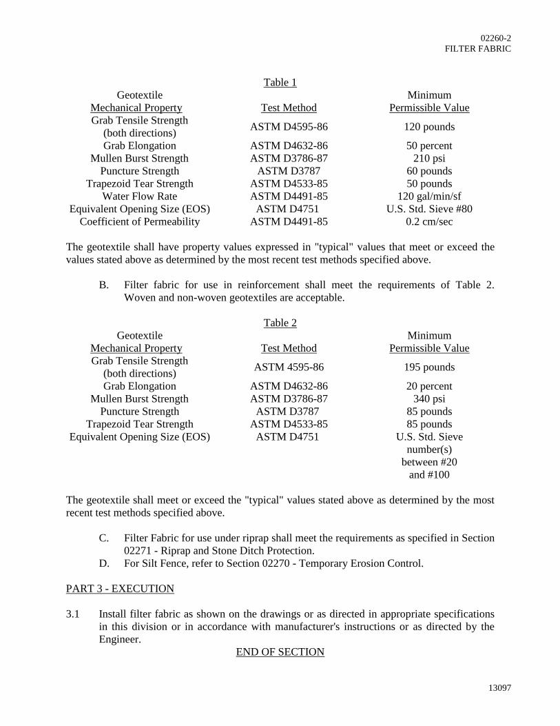
02260-2
FILTER FABRIC
13097
Table 1
Geotextile
Mechanical Property Test Method
Minimum
Permissible Value
Grab Tensile Strength
(both directions) ASTM D4595-86 120 pounds
Grab Elongation ASTM D4632-86 50 percent
Mullen Burst Strength ASTM D3786-87 210 psi
Puncture Strength ASTM D3787 60 pounds
Trapezoid Tear Strength ASTM D4533-85 50 pounds
Water Flow Rate ASTM D4491-85 120 gal/min/sf
Equivalent Opening Size (EOS) ASTM D4751 U.S. Std. Sieve #80
Coefficient of Permeability ASTM D4491-85 0.2 cm/sec
The geotextile shall have property values expressed in "typical" values that meet or exceed the
values stated above as determined by the most recent test methods specified above.
B. Filter fabric for use in reinforcement shall meet the requirements of Table 2.
Woven and non-woven geotextiles are acceptable.
Table 2
Geotextile
Mechanical Property Test Method
Minimum
Permissible Value
Grab Tensile Strength
(both directions) ASTM 4595-86 195 pounds
Grab Elongation ASTM D4632-86 20 percent
Mullen Burst Strength ASTM D3786-87 340 psi
Puncture Strength ASTM D3787 85 pounds
Trapezoid Tear Strength ASTM D4533-85 85 pounds
Equivalent Opening Size (EOS) ASTM D4751 U.S. Std. Sieve
number(s)
between #20
and #100
The geotextile shall meet or exceed the "typical" values stated above as determined by the most
recent test methods specified above.
C. Filter Fabric for use under riprap shall meet the requirements as specified in Section
02271 - Riprap and Stone Ditch Protection.
D. For Silt Fence, refer to Section 02270 - Temporary Erosion Control.
PART 3 - EXECUTION
3.1 Install filter fabric as shown on the drawings or as directed in appropriate specifications
in this division or in accordance with manufacturer's instructions or as directed by the
Engineer.
END OF SECTION

13097
02270-1
SECTION 02270
TEMPORARY EROSION CONTROL
PART 1 - GENERAL
1.1 DESCRIPTION
A. Work Included:
1. The work under this section shall include provision of all labor, equipment,
materials and maintenance of temporary erosion control devices as specified
herein, and as directed by the Engineer.
2. Erosion control measures shall be provided as necessary to correct conditions
that develop prior to the completion of permanent erosion control devices or
as required to control erosion that occurs during normal construction
operations.
3. Construction operations shall comply with all federal, state and local
regulations pertaining to erosion control.
4. Erosion control measures shall be in accordance with the Massachusetts
Department of Environmental Protection's - Stormwater Management
Standards - (referred to hereafter as MassDEP SMS) and "Massachusetts
Erosion and Sediment Control Guidelines for Urban and Suburban Areas,"
Franklin, Hampden, Hampshire Conservation Districts, 2003), and Town of
Barnstable Conservation Commission Standards.
5. After awarded the Contract, prior to commencement of construction activities,
meet with the Engineer to discuss erosion control requirements and develop a
mutual understanding relative to details of erosion control.
B. Design Criteria:
1. Conduct all construction in a manner and sequence that causes the least
practical disturbance of the physical environment.
2. Stabilize disturbed earth surfaces in the shortest time and employ such
temporary erosion control devices as may be necessary until such time as
adequate soil stabilization has been achieved.
1.2 SUBMITTALS
A. The Contractor shall furnish the Engineer, in writing, his work plan giving proposed
locations for storage of topsoil and excavated material before beginning
construction. A schedule of work shall accompany the work plan. Acceptance of
this plan will not relieve the Contractor of the responsibility of completion of the
work as specified.
1.3 QUALITY ASSURANCE
A. All materials and methods of erosion control shall meet the guidelines established
by the "Massachusetts Stormwater Handbook” published by the Massachusetts
Department of Environmental Protection and "Massachusetts Erosion and Sediment
Control Guidelines for Urban and Suburban Areas," Franklin, Hampden,
Hampshire Conservation Districts, 2003

02270-2
TEMPORARY EROSION CONTROL
13097
PART 2 - PRODUCTS
2.1 MATERIALS
A. Fiber Rolls:
1. The owner has a preference for fiber rolls (a.k.a. straw wattles) over hay bales
for erosion control. Fiber rolls shall be minimum 9-inch diameter cylinders of
agricultural straw or rice straw wrapped in photodegradable black synthetic
netting.
B. Silt Fencing
1. Polyethylene, polypropylene, nylon, or polyester fabric supported by stakes
spaced no greater than 6-feet apart.
C. Silt Sacks:
1. Silt Sacks (or equivalent) shall be placed in downgradient catch basins to
prevent sediment from entering the drainage system. Silt sacks shall be
periodically cleaned while in use and must be cleaned prior to and after
precipitation events. Applicants are advised they may be required to respond
immediately for repair and maintenance at the request of the Town within two
hours of notification.
D. Mulches:
1. Straw or Salt Marsh Hay. Loose hay mulching is prohibited.
E. Mats and Nettings:
1. Twisted Craft paper, yarn, jute, excelsior wood fiber mats, glass fiber and
plastic film.
2. Type and use shall be as specified in the SMS.
F. Baled Straw:
1. At least 14" by 18" by 30" securely tied to form a firm bale, staked as
necessary to hold the bale in place.
G. Sand Bags:
1. Heavy cloth bags of approximately one cubic foot capacity filled with sand or
gravel.
H. Permanent Seed:
1. Conservation mix appropriate to the predominant soil conditions as specified
in the SMS and subject to approval by the Engineer.
I. Temporary Seeding:
1. Use species appropriate for soil conditions and season as specified in the SMS
and subject to approval by the Engineer.
J. Water:
1. The Contractor shall provide water and equipment to control dust, as directed
by the Engineer.
K. Filter Fabrics:
1. Filter fabric shall be of one of the commercially available brands such as
Mirafi, Typar or equivalent. Fabric types for particular applications shall be
approved by the Engineer prior to installation.
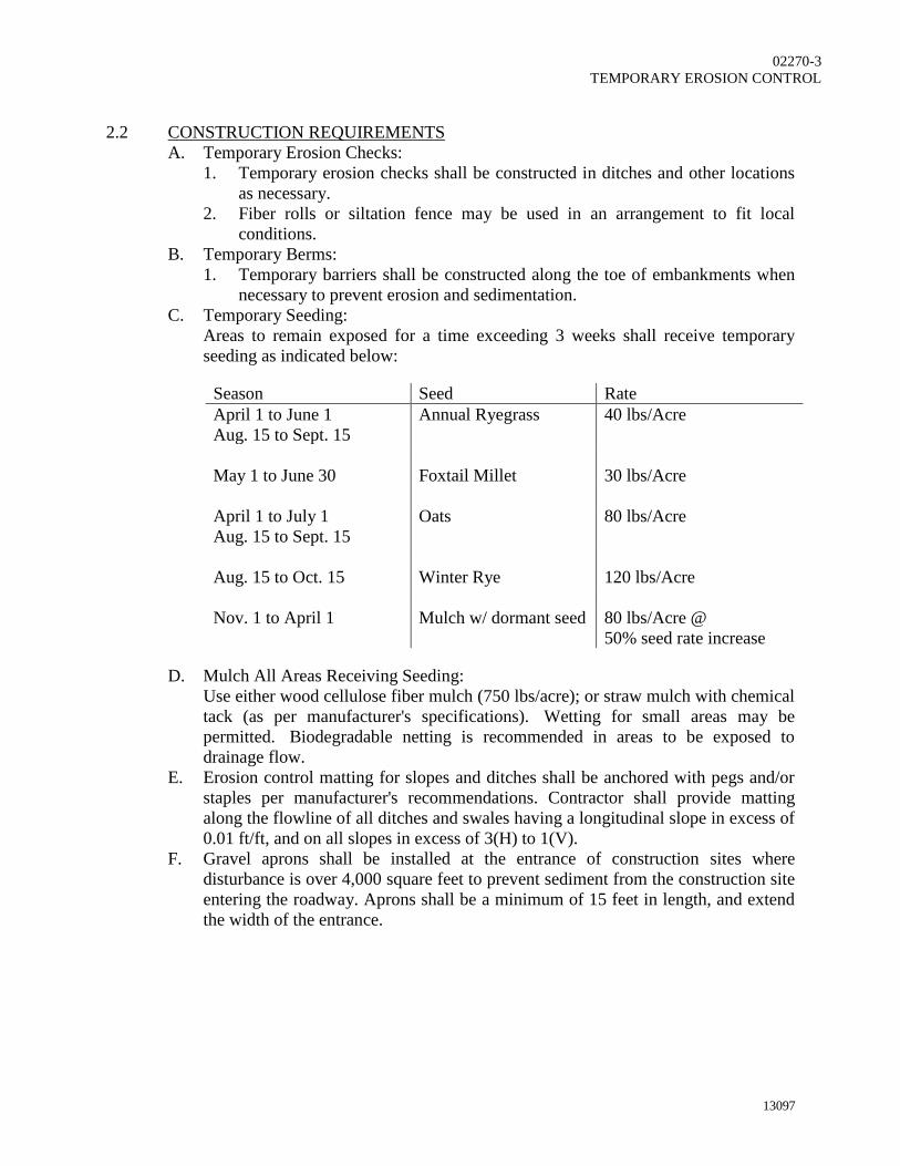
02270-3
TEMPORARY EROSION CONTROL
13097
2.2 CONSTRUCTION REQUIREMENTS
A. Temporary Erosion Checks:
1. Temporary erosion checks shall be constructed in ditches and other locations
as necessary.
2. Fiber rolls or siltation fence may be used in an arrangement to fit local
conditions.
B. Temporary Berms:
1. Temporary barriers shall be constructed along the toe of embankments when
necessary to prevent erosion and sedimentation.
C. Temporary Seeding:
Areas to remain exposed for a time exceeding 3 weeks shall receive temporary
seeding as indicated below:
Season Seed Rate
April 1 to June 1
Aug. 15 to Sept. 15
Annual Ryegrass 40 lbs/Acre
May 1 to June 30 Foxtail Millet 30 lbs/Acre
April 1 to July 1
Aug. 15 to Sept. 15
Oats 80 lbs/Acre
Aug. 15 to Oct. 15 Winter Rye 120 lbs/Acre
Nov. 1 to April 1 Mulch w/ dormant seed 80 lbs/Acre @
50% seed rate increase
D. Mulch All Areas Receiving Seeding:
Use either wood cellulose fiber mulch (750 lbs/acre); or straw mulch with chemical
tack (as per manufacturer's specifications). Wetting for small areas may be
permitted. Biodegradable netting is recommended in areas to be exposed to
drainage flow.
E. Erosion control matting for slopes and ditches shall be anchored with pegs and/or
staples per manufacturer's recommendations. Contractor shall provide matting
along the flowline of all ditches and swales having a longitudinal slope in excess of
0.01 ft/ft, and on all slopes in excess of 3(H) to 1(V).
F. Gravel aprons shall be installed at the entrance of construction sites where
disturbance is over 4,000 square feet to prevent sediment from the construction site
entering the roadway. Aprons shall be a minimum of 15 feet in length, and extend
the width of the entrance.

02270-4
TEMPORARY EROSION CONTROL
13097
PART 3 - EXECUTION
3.1 INSTALLATION
A. Fiber Rolls (Straw Wattles):
Fiber rolls shall be staked securely into the ground and oriented perpendicular to
the slope using wood takes. A minimum of 3 inches of the stake should stick out
above the roll. Stakes shall be spaced 3 to 4 feet apart.
B. Silt Fencing:
Silt fence shall be erected in a continuous fashion from a single roll of fabric. The
bottom of the fabric fence shall be buried sufficiently below the ground surface to
prevent gaps from forming, usually 4 to 6 inches below ground surface. The fabric
shall be installed on the upstream side of the stakes. Stakes shall be strong enough
and tall enough to securely anchor the fabric to the ground. Stake spacing shall be
no more than 10 feet apart for extra-strength fabric and 6 feet apart for standard
strength fabric. Maintenance of the fence is required during construction. Material
shall be based on the synthetic fabric requirements as follows:
1. Filtering efficiency: 75% (minimum)
2. Tensile strength: Standard strength: 30lb/linear inch (minimum), Extra
strength: 50 lb/linear inch (minimum)
3. Elongation: 20% (maximum)
4. Ultraviolet radiation: 90% (minimum)
5. Slurry flow rate: 0.3 gal/ft2/min (minimum)
C. Temporary Erosion Checks:
1. Temporary erosion checks shall be constructed in ditches and at other
locations designated by the Engineer. The Engineer may modify the
Contractor's arrangement of silt fences, bales and bags to fit local conditions.
2. Fiber rolls, baled straw, silt fences, or some combination, may be used in
other areas, as necessary, to inhibit soil erosion.
3. Siltation fence shall be located and installed as shown on plans or as required
to comply with all Federal, State and Local Regulations.
4. Sedimentation ponds shall be sited and constructed to the grades and
dimensions as shown on the Drawings and will include drainage pipe and an
emergency spillway.
D. Erosion control matting for slopes and ditches shall be installed where indicated on
the Drawings and as required to stabilize the soil until permanent vegetative
stabilization is established.
E. Maintenance:
Erosion control features shall be installed prior to excavation wherever
appropriate. Temporary erosion control features shall remain in place and shall be
maintained until a satisfactory growth of grass is established. The Contractor shall
be responsible for maintaining erosion control features throughout the life of the
construction contract. Maintenance will include periodic inspections by the Owner
or Engineer for effectiveness of location, installation and condition with corrective
action taken by the Contractor, as appropriate.
F. Removing and Disposing of Materials:
1. When no longer needed, material and devices for temporary erosion control
shall be removed and disposed of upon approval by Engineer.

02270-5
TEMPORARY EROSION CONTROL
13097
2. When removed, such devices may be reused in other locations, provided they
are in good condition and suitable to perform the erosion control for which
they are intended.
3. When dispersed over adjacent areas, the material shall be scattered to the
extent that it causes no unsightly conditions nor creates future maintenance
problems.
4. Sedimentation basins, if no longer required, will be filled in, the pipe
removed, the surface loamed and grass cover shall be established.
END OF SECTION

12933A
02401-1
SECTION 02401
COFFERDAMS AND DEWATERING
PART 1 - GENERAL
1.1 DESCRIPTION
A. Work Included:
1. Furnish, operate and maintain, as incidental to the project, dewatering
equipment to lower and control surface waters, ground waters, and hydrostatic
pressures to permit excavation, backfill, and/or construction to be performed
effectively; collect and dispose of ground and surface water where necessary
to complete the work. .
1.2 SUBMITTALS
A. Provide submittals in accordance with Specification Section 01340. Submit design
calculations (if applicable), description, details, and complete layout drawings of
the proposed cofferdam and dewatering system. Such review shall not relieve the
Contractor of sole responsibility for the cofferdam and dewatering system as
necessary to prevent damage and settlement to adjacent structures, utilities, streets
adjacent to excavations and for the safety of persons working within the excavated
areas.
B. Submittal shall include: location, depth and size of headers, sumps, ditches; size
and location of discharge lines; capacities of pumps and standby units, and detailed
description of cofferdam and dewatering methods to be employed to convey the
water from site to adequate disposal.
1.3 DESIGN
A. Dewatering system shall be of sufficient size and capacity necessary to facilitate
construction. Materials to be removed shall be sufficiently dewatered to permit
visual and survey confirmation of grades shown. Operate dewatering system
continuously until associated construction work has been completed.
B. Control of surface and subsurface water is part of dewatering system requirements.
Maintain adequate control so that:
1. The stability of excavated and constructed slopes are not adversely affected by
saturated soil, including water entering prepared subbase and subgrades where
underlying materials are not free draining or are subject to swelling or freeze-
thaw action.
2. Erosion is controlled.
3. Flooding of excavations or damage to structures does not occur.
4. Surface water drains away from excavations.
5. Excavations are protected from becoming wet from surface water, or insure
excavations are dry before additional work is undertaken
6. Prevent loss of fines, seepage, boils, quick conditions or softening of
foundation strata.

02401-2
COFFERDAMS AND DEWATERING
12933A
7. Maintain stability of sides and bottom of excavation. Construction operations
are performed in the dry.
8. Any existing dewatering wells that can affect dewatering and excavation shall
be sealed below the excavation subgrade.
PART 2 - PRODUCTS
2.1 COFFERDAM MATERIALS
A. The term cofferdam designates any temporary or removable structure which is
constructed to hold the surrounding water out of the excavation, whether such
structure is formed of aggregates, timber, steel, concrete, plastic, or a combination
of these. It thus includes sand bags, water filled bladders, timber cribs, any type of
sheet piling, removable steel sheets and the like and all necessary bracing; and it
shall also be understood to include the use of applicable pumping systems or well
points (as outlined above).
B. The type and clearance of the cofferdam will be subject to the approval of the
Engineer. The Contractor is responsible for the successful completion of the work
and to provide a coffer dam system as needed that shall have interior dimensions
such as to provide sufficient clearance for the construction and removal of any
required materials and the inspection of their exteriors and to permit pumping
outside of the area of work.
C. The design, implementation, operation, and maintenance of the cofferdam system
shall be in accordance with all applicable OSHA specifications.
PART 3 - EXECUTION
3.1 PERFORMANCE
A. General:
1. Keep work areas dewatered until the structures, and appurtenances to be built
there have been completed to such an extent that they will not be damaged by
water.
2. Maintain standby backup equipment and power supply throughout the
duration of the dewatering operation.
3. Prevent soil particles from entering the discharge points.
B. Disposal of Water:
1. Dispose of water pumped or drained from the construction site in a suitable
manner to avoid siltation of adjacent drainage structures and piping, wetlands
or water bodies, injury to public health, damage to public and private
property, and damage to the work completed or in progress.
2. Provide suitable temporary channels for water that may flow along or across
the construction site.
3. Provide treatment as necessary to prevent discharge of contaminated ground
water caused by Contractor's operations, or any contaminated ground water
that may pass through the excavation support system selected by the
Contractor.

02401-3
COFFERDAMS AND DEWATERING
12933A
4. Contractor must obtain all necessary regulatory approvals for the disposal of
dewatering flows. These may include, among others, approval by the USEPA
under the National Pollutant Discharge Elimination System (NPDES) program
for construction activities.
C. Excavation Sump Pumping:
1. When necessary and where appropriate, the work area may be over excavated
6 to 12 inches and filled with screened stone to allow sump pumping of
groundwater.
2. The system shall be installed with suitable screens and filters so that pumping
of fines does not occur.
D. Well and Wellpoint System:
1. If necessary, dewater the excavations and trenches with an efficient well or
wellpoint system to drain the soil and prevent saturated soil from flowing into
the excavated wells and area.
2. Wellpoint and well system shall be of the type designed for dewatering work
and shall be installed with suitable screens and filters so that pumping of fines
does not occur.
3. Pumping units shall be capable of maintaining sufficient suction to handle
large volumes of air and water at the same time.
E. Corrective Action:
1. If dewatering requirements are not satisfied due to inadequacy or failure of the
dewatering system (loosening of the foundation strata, or instability of slopes,
or damage to foundations or structures), perform work necessary for
reinstatement of foundation soil and damaged structure resulting from such
inadequacy or failure by Contractor, at no additional cost to Owner.
END OF SECTION
13097
02485-1
SECTION 02485
LOAMING & SEEDING
PART 1 - GENERAL
1.1 DESCRIPTION
A. Work Included: Furnish, place, and test topsoil, seed, lime, and fertilizer where
shown on the drawings and protect and maintain seeded areas disturbed by
construction work, as directed by the Engineer.
B. Related Work Specified Elsewhere (When Applicable): Earthwork, excavation,
backfill, compaction, site grading and temporary erosion control are specified in the
appropriate Sections of this Division.
1.2 SUBMITTALS AND TESTING
A. Seed:
1. Furnish the Engineer with duplicate signed copies of a statement from the
vendor, certifying that each container of seed delivered to the project site is
fully labeled in accordance with the Federal Seed Act and is at least equal to
the specification requirements.
2. This certification shall appear in, or with, all copies of invoices for the seed.
3. The certification shall include the guaranteed percentages of purity, weed
content and germination of the seed, and also the net weight and date of
shipment. No seed may be sown until the Contractor has submitted the
certificates and certificates have been approved.
4. Each lot of seed shall be subject to sampling and testing, at the discretion of
the Engineer, in accordance with the latest rules and regulations under the
Federal Seed Act.
B. Topsoil:
1. Inform the Engineer, within 30 days after the award of the Contract, of the
sources from which the topsoil is to be furnished.
2. Obtain representative soil samples, taken from several locations in the area
under consideration for topsoil removal, to the full stripping depth.
3. Have soil samples tested by an independent soils testing laboratory, approved
by the Engineer, at the Contractor's expense.
4. Have soil samples tested for physical properties and pH (or lime requirement),
for organic matter, available phosphoric acid, and available potash, in
accordance with standard practices of soil testing.
5. Approval, by the Engineer, to use topsoil for the work will be dependent upon
the results of the soils tests.
C. Lime & Fertilizer:
1. Furnish the Engineer with duplicate copies of invoices for all lime and
fertilizer used on the project showing the total minimum carbonates and
minimum percentages of the material furnished that pass the 90 and 20 mesh
sieves and the grade furnished.

02485-2
LOAMING & SEEDING
13097
2. Each lot of lime and fertilizer shall be subject to sampling and testing at the
discretion of the Engineer.
3. Sampling and testing shall be in accordance with the official methods of the
Association of Official Agricultural Chemists.
4. Upon completion of the project, a final check may be made comparing the
total quantities of fertilizer and lime used to the total area seeded. If the
minimum rates of application have not been met, the Engineer may require the
Contractor to distribute additional quantities of these materials to meet the
minimum rates.
1.3 DELIVERY, STORAGE & HANDLING
A. Seed:
1. Furnish all seed in sealed standard containers, unless exception is granted in
writing by the Engineer.
2. Containers shall be labeled in accordance with the United States Department
of Agriculture's rules and regulations under the Federal Seed Act in effect at
the time of purchase.
B. Fertilizer:
1. Furnish all fertilizer in unopened original containers.
2. Containers shall be labeled with the manufacturer's statement of analysis.
1.4 JOB CONDITIONS
A. Topsoil: Do not place or spread topsoil when the subgrade is frozen, excessively
wet or dry, or in any condition otherwise detrimental, in the opinion of the
Engineer, to the proposed planting or to proper grading.
B. Seeding:
1. Planting Seasons: The recommended seeding time is from April 1 to
September 15. The Contractor may seed at other times. Regardless of the
time of seeding, the Contractor shall be responsible for each seeded area until
it is accepted.
2. Weather Conditions:
a. Do not perform seeding work when weather conditions are such that
beneficial results are not likely to be obtained, such as drought,
excessive moisture, or high winds.
b. Stop the seeding work when, in the opinion of the Engineer, weather
conditions are not favorable.
c. Resume the work only when, in the opinion of the Engineer, conditions
become favorable, or when approved alternate or corrective measures
and procedures are placed into effect.
PART 2 - PRODUCTS
2.1 MATERIALS
A. Seed:
1. Provide an erosion seed mixture approved by the Engineer, having the
following composition:

02485-3
LOAMING & SEEDING
13097
Seed %Weight %Germination Minimum
Winter Rye 80 Minimum 85
Red Fescue 4 Minimum 80
Perennial Rye 3 Minimum 90
Red Clover 3 Minimum 90
Other Crop Grass 0.5 Maximum
Noxious Weed 0.5 Maximum
Inert Matter 1.0 Maximum
2. Do not use seed which has become wet, moldy, or otherwise damaged in
transit or during storage.
B. Topsoil:
1. Fertile, friable, natural topsoil typical of the locality, without admixture of
subsoil, refuse or other foreign materials and obtained from a well-drained
site. Mixture of sand, silt, and clay particles in equal proportions.
2. Free of stumps, roots, heavy of stiff clay, stones larger than 1-inch in
diameter, lumps, coarse sand, weeds, sticks, brush or other deleterious matter.
3. Not less than 4 percent nor more than 20 percent organic matter.
4. Topsoil depth shall be 4-inches, unless otherwise indicated.
C. Lime:
1. Provide lime which is ground limestone containing not less than 85% of total
carbonate and of such fineness that 90% will pass a No. 20 sieve and 50% will
pass a No. l00 sieve.
2. Coarser materials will be acceptable provided the specified rates of
application are increased proportionately on the basis of quantities passing a
No. l00 sieve. No additional payment will be made to the Contractor for the
increased quantity.
D. Fertilizer:
1. Provide a commercial fertilizer approved by the Engineer.
2. Provide fertilizer containing the following minimum percentage of nutrients
by weight:
l0% Available phosphoric acid
l0% Available potash
l0% Available nitrogen (75% of the nitrogen shall be organic)
PART 3 - EXECUTION
3.1 PREPARATION
A. Equipment:
1. Provide all equipment necessary for the proper preparation of the ground
surface and for the handling and placing of all required materials.
2. Demonstrate to the Engineer that the equipment will apply materials at the
specified rates.
B. Soil: Perform the following work prior to the application of lime, fertilizer or seed.

02485-4
LOAMING & SEEDING
13097
1. Scarify the subgrade to a depth of 2 inches to allow the bonding of the topsoil
with the subsoil.
2. Apply topsoil to a depth of 4 inches or as directed on areas to be seeded.
3. Trim and rake the topsoil to true grades free from unsightly variations, humps,
ridges or depressions.
4. Remove all objectionable material and form a finely pulverized seed bed.
3.2 PERFORMANCE
A. Grading:
1. Grade the areas to be seeded as shown on the Drawings or as directed by the
Engineer.
2. Leave all surfaces in even and properly compacted condition.
3. Maintain grades on the areas to be seeded in true and even conditions,
including any necessary repairs to previously graded areas.
B. Placing Topsoil:
1. Uniformly distribute and evenly spread topsoil on the designated areas.
2. Spread the topsoil in such a manner that planting work can be performed with
little additional soil preparation or tillage.
3. Correct any irregularities in the surface resulting from top soiling or other
operations to prevent the formation of depressions where water may stand.
4. Thoroughly till the topsoil to a depth of at least 3 inches by plowing,
harrowing, or other approved method until the condition of the soil is
acceptable to the Engineer. The surface shall be cleared of all debris and or
stones one inch or more in diameter.
C. Placing Fertilizer:
1. Distribute fertilizer uniformly at a rate determined by the soils test over the
areas to be seeded.
2. Incorporate fertilizer into the soil to a depth of at least 3 inches by discing,
harrowing, or other methods acceptable to the Engineer.
3. The incorporation of fertilizer may be a part of the tillage operation specified
above.
4. Distribution by means of an approved seed drill equipped to sow seed and
distribute fertilizer at the same time will be acceptable.
D. Placing Lime:
1. Uniformly distribute lime immediately following or simultaneously with the
incorporation of fertilizer.
2. Distribute lime at a rate determined from the pH test, to a depth of at least 3
inches by discing, harrowing, or other methods acceptable to the Engineer.
E. Seeding:
1. Fine rake and level out any undulations or irregularities in the surface
resulting from tillage, fertilizing, liming or other operations before starting
seeding operations.
2. Hydroseeding:
a. Hydroseeding may be performed where approved and with equipment
approved by the Engineer.
02485-5
LOAMING & SEEDING
13097
b. Sow the seed over designated areas at a minimum rate of 5 pounds per
1000 square feet.
c. Seed and fertilizing materials shall be kept thoroughly agitated in order
to maintain a uniform suspension within the tank of the hydroseeder.
d. The spraying equipment must be designed and operated to distribute
seed and fertilizing materials evenly and uniformly on the designated
areas at the required rates.
3. Drill Seeding:
a. Drill seeding may be performed with approved equipment having drills
not more than 2 inches apart.
b. Sow the seed uniformly over the designated areas to a depth of l/2 inch
and at a rate of 5 pounds per l,000 square feet.
4. Broadcast Seeding:
a. Broadcast seeding may be performed by equipment approved by the
Engineer.
b. Sow the seed uniformly over the designated areas at a rate of 5 pounds
per l,000 square feet.
c. Sow half the seed with the equipment moving in one direction and the
remainder of the seed with the equipment moving at right angles to the
first sowing.
d. Cover the seed to an average depth of l/2 inch by means of a brush
harrow, spike-tooth harrow, chain harrow, cultipacker, or other approved
devices.
e. Do not perform broadcast seeding work during windy weather.
F. Compacting:
1. Seeded areas must be raked lightly after sowing unless seeding is to be
directly followed by application of an approved mulch.
2. Compact the entire area immediately after the seeding operations have been
completed.
3. Compact by means of a cultipacker, roller, or other equipment approved by
the Engineer weighing 60 to 90 pounds per linear foot of roller.
4. If the soil is of such type that a smooth or corrugated roller cannot be operated
satisfactorily, use a pneumatic roller (not wobbly wheel) that has tires of
sufficient size to obtain complete coverage of the soil.
5. When using a cultipacker or similar equipment, perform the final rolling at
right angles to the prevailing slopes to prevent water erosion, or at right angles
to the prevailing wind to prevent dust.
3.3 PROTECTION & MAINTENANCE
A. Protection:
1. Protect the seeded area during initial growth period
2. Erect barricades and place warning signs as needed.
B. Maintenance:
1. Maintenance shall also include all temporary protection fences, barriers and
signs and all other work incidental to proper maintenance.

02485-6
LOAMING & SEEDING
13097
2. Maintain grass areas until a full stand of grass is indicated, which will be a
minimum of 45 days after all seeding work is completed, and shall not
necessarily related to Substantial Completion of the General Contract.
3. Protection and maintenance of grass areas shall consist repair of any erosion
and reseeding as necessary to establish a uniform stand for the specified
grasses, and shall continue until Acceptance by the Engineer of the work of
this section.
3.4 ACCEPTANCE
A. At final acceptance of the project all areas shall have a close stand of grass with no
weeds present and no bare spots greater than three inches (3") in diameter over
greater than five percent (5%) of the overall seeded area.
END OF SECTION

13097
03300-1
SECTION 03300
CAST-IN-PLACE CONCRETE
PART 1 - GENERAL
1.1 SECTION INCLUDES
A. Cast-In-Place Concrete
B. Formwork
C. Concrete reinforcement and accessories
D. Modifications and/or Repairs to concrete
E. Concrete curing
F. Concrete finishing
G. Concrete repairs
H. Concrete testing
I. Non-Shrink Grout
1.2 RELATED SECTIONS
A. Section 01340 - Submittals
B. Section 01400 - Quality Control
1.3 REFERENCES
A. ACI 211.1-91 (2009) - Standard Practice for Selecting Proportions for Normal,
Heavyweight, and Mass Concrete
B. ACI 301-10 - Standard Specifications for Structural Concrete
C. ACI 302.1R-04 - Guide for Concrete Floor and Slab Construction
D. ACI 304.2R-96 (2008) - Placing Concrete by Pumping Methods
E. ACI 305R-10 - Hot Weather Concreting
F. ACI 306.1-90 (2002) - Standard Specification for Cold Weather Concreting
G. ACI 308R-01 (2008) - Guide to Curing Concrete
H. ACI 308.1-98 - Standard Specification for Curing Concrete
I. ACI 309R-05 - Guide for Consolidation of Concrete
J. ACI 318-08 - Building Code Requirements for Structural Concrete and
Commentary
K. ACI 347R-04 - Guide to Formwork for Concrete
L. ACI 350-06 - Code Requirements for Environmental Engineering Concrete
Structures and Commentary
M. ASTM A82-M-07 - Specification for Steel Wire, Plain, for Concrete Reinforcement
N. ASTM A185-M-07 - Specification for Steel Welded Wire Fabric, Plain for
Concrete Reinforcement
O. ASTM A615/ A615M-09b for Concrete Reinforcement - Specification for
Deformed and Plain Billet - Steel Bars
P. ASTM C31/C31M-10 - Standard Practice for Making and Curing Concrete Test
Specimens in the Field
Q. ASTM C33-11 - Specification for Concrete Aggregates
R. ASTM C39/C39M-10 - Standard Test Method for Compressive Strength of

03300-2
CAST-IN-PLACE CONCRETE
13097
Cylindrical Concrete Specimens
S. ASTM C42/C42M-10a Standard Test Method of Obtaining and Testing Drilled
Cores and Sawed Beams of Concrete
T. ASTM C94/C94M-11 - Specification for Ready Mixed Concrete
U. ASTM C150-09 - Specification for Portland Cement
V. ASTM C172-10 - Practice for Sampling Freshly Mixed Concrete
W. ASTM C231-10 - Test Method for Air Content of Freshly Mixed Concrete by the
Pressure Method
X. ASTM C260-10a - Specification for Air Entraining Admixtures for Concrete
Y. ASTM C309R-07 - Guide for Consolidation of Concrete
Z. ASTM C494/C494M-10a - Specification for Chemical Admixtures for Concrete
AA. ASTM C595-10 - Specification for Blended Hydraulic Cements
BB. ASTM C618-08a - Specification for Coal Fly Ash and Raw or Calcined Natural
Pozzolan for Use in Concrete
CC. ASTM C881/C881M-10 - Specification for Epoxy-Resin-Base Bonding Systems
for Concrete
DD. ASTM C989-10 - Specification for Ground Granulated Blast-Furnace Slag for Use
in Concrete and Mortars
EE. ASTM C1107/C1107M-11 - Specification for Packaged Dry, Hydraulic-Cement
Grout (Nonshrink)
FF. ASTM C1240-10a - Specification for Silica Fume Used in Cementitious Mixtures
GG. ASTM C1602-06 - Specification for Mixing Water Used in the Production of
Hydraulic Cement Concrete
HH. ASTM E 329-11 - Specification for Agencies Engaged in the Testing and/or
Inspection of Materials Used in Construction
II. Concrete Reinforcing Steel Institute - Manual of Standard Practice
JJ. Concrete Reinforcing Steel Institute - Placing Reinforcing Bars
1.4 QUALITY ASSURANCE
A. Perform work in accordance with ACI 301, ACI 318 and ACI 350 as modified
here-in.
B. Maintain copies of ACI 301, ACI 318, and ACI 350 on site.
1.5 QUALIFICATIONS OF INDEPENDENT TESTING LABORATORY
A. Independent Testing Laboratory shall conform to concrete testing requirements of
ASTM E329.
B. Key personnel must be qualified and experienced in concrete quality assurance.
C. Perform concrete field quality control testing with personnel certified as an ACI
Concrete Field Testing Technician, Grade 1 according to the American Concrete
Institute (ACI).
1.6 SUBMITTALS
A. Submit layout drawings showing the location and extent of all joint waterstops, the
type and size of all waterstops to be used and splice locations for each
joint. Submit these layout drawings for review prior to the submittal of the
reinforcing shop drawings and the start of concrete work.
B. Submit shop drawings for concrete reinforcement prior to fabrication, showing bar

03300-3
CAST-IN-PLACE CONCRETE
13097
bends, details and placement. Submit reinforcement for cast in place concrete and
concrete masonry.
C. Submit Concrete Mix designs including past field performance test results which
meet the criteria specified in Chapter 5 of ACI 318.
D. Submit sieve analysis and soundness tests for fine and coarse aggregates taken
within the last three (3) months.
E. Submit Cement Manufacturer's Certificates of conformance with ASTM C150
taken during the last 3 months.
F. For all pozzolans proposed, submit certificates of conformance with respective
ASTM standards indicated in Part 2.3.A of this specification.
G. Submit sample concrete mix delivery slip.
H. Submit product data for concrete curing, sealing and hardening compounds.
Indicate the intended use and location for all products.
I. Independent Testing Laboratory will submit one copy each of all test reports to
each of the following: Engineer, Resident Project Representative, Contractor and
Concrete Supplier.
J. Independent Testing Laboratory will submit reports within 5 days of testing or
inspection.
K. Independent Testing Laboratory will telephone the Engineer within 24 hours if tests
indicate deficiencies.
L. Submit a conduit layout plan under the appropriate sections of Division 16.
M. Submit a written outline of cold weather protection measures, hot weather
protection measures, and curing methods.
N. Contractor shall submit all requested information prior to the pre-concrete meeting.
PART 2 - PRODUCTS
2.1 FORM MATERIALS
A. Plywood: APA, B-B Plyform Class I exterior.
B. Lumber: Southern pine, No. 2 grade or equal.
C. Steel: Minimum 16 ga. sheet, well matched, tight fitting, stiffened to resist loads
without excess deflection.
D. Form Ties: snap-off type, galvanized metal, adjustable lengths designed to break
back at least 1 inch from finished surface or ties as indicated above.
E. Form release agent: non-staining colorless, compatible with finishes. Super-X
Emulsive by A.H. Harris & Sons, Inc., StarSeal EF Bio-Release by Vexcon, Q-2
Form Release by Unitex or equivalent.
F. Conform to ACI 301 and ACI 347
2.2 REINFORCING STEEL
A. Bars: ASTM A615 Grade 60; deformed new materials.
B. Welded wire fabric: ASTM A185
C. Tie wire: ASTM A82, annealed.
D. Bolsters, chairs and supports: plastic coated, stainless steel, or epoxy coated.
E. Conform to CRSI Code of Standard Practice-Fabrication.
2.3 CAST-IN-PLACE CONCRETE

03300-4
CAST-IN-PLACE CONCRETE
13097
A. Concrete Materials
1. Portland cement: ASTM C150; Type II. Tricalcium Aluminate (C3A)
content in cement less than 8%. Cement shall be furnished from one source
during the project.
2. Pozzolans:
a. Ground Granulated Blast Furnace Slag: ASTM C989 - Grade 120.
b. Fly Ash: ASTM C618 - Type F
3. Aggregates:
a. Fine aggregate shall consist of washed inert natural sand conforming to
the requirements of ASTM Specification C-33.
b. Coarse aggregate shall consist of a well graded crushed stone or a
washed gravel conforming to the requirements of ASTM Specification
C-33.
4. Water: Potable from municipal water supply or shall meet the requirements of
ASTM C1602.
5. Admixtures: All from one common manufacturer.
B. Admixtures
1. Low Range Water Reducer: Pozzolith 210 by Master Builders; WRDA with
HYCOL by Grace Construction Products Division; or equivalent meeting
ASTM C494 Type A.
2. High Range Water Reducer (superplasticiser): Rheobuild 1000 or Glenium
3000 NS by Master Builders; Daracem 100 or ADVA 140M by W.R. Grace;
or equivalent meeting ASTM C494 Type F.
3. Air entraining agent: Micro-Air by Master Builders, DAREX II AEA by
Grace Construction Products; or equivalent meeting ASTM C260.
4. Non-corrosive non-chloride accelerator: Pozzutec 20+ by Master Builders;
Polarset by W. R. Grace or equivalent meeting ASTM C494 type C or E.
5. Not permitted: Calcium chloride, thiocyanates or admixtures containing more
than 0.05% chloride ions.
C. Concrete
1. Concrete Class
a. Reinforced concrete sections: Class A
b. Concrete fill, conduit and pipe encasements: Class B
2. Concrete proportioning shall conform to ACI 318, Chapter 5 except as
modified below:
Min.-Max. Slump
Class
Strength (f'c)
Coarse
Aggregate
% Air
± (1.5%)
Cem.Fac
(LB/CY)
Max W/C
Ratio
w/o
HRWR
w/ HRWR
A 4000 PSI No. 67 (3/4") 6 564-620 0.42 1-3 4-8
B 3000 PSI No. 8 (3/8") 6 517-564 0.50 2-5 N/A
3. An alternate concrete mix design using blended hydraulic cements and
pozzolans may be proposed. Any alternate mix design proposed shall include
a minimum of 30 compressive strength test results from the past 12 months
exhibiting a consistent strength and standard deviation. The proposed mix

03300-5
CAST-IN-PLACE CONCRETE
13097
shall contain cementitious materials in the following proportions
a. Portland Cement - No less than 75% of the total by weight.
b. Ground Granulated Blast Furnace Slag - No greater than 25% of the
total by weight.
c. Fly Ash - No greater than 15% of the total by weight.
4. The maximum slump as indicated in the above table will be as measured at the
batch plant.
5. Concrete pumping shall conform to ACI 304 unless otherwise indicated herein
6. High range water reducer shall be added either at the concrete batch plant or
on site for Class A mixes to obtain the slumps as indicated above.
7. No additional mix water shall be added to the concrete on site which will
increase the water-cement ratio of the mix. If additional water is to be added
on site, it shall be held back from the specified quantity in the mix design
during batching and shall be added on-site for the sole purpose of providing
the initial sump as specified prior to adding the high range water reducer. The
amount of water held back from the mix shall be clearly indicated on the
concrete mix delivery slip. The Resident Project Representative shall be
notified prior to adding the water on site. The addition of a greater quantity of
water than that indicated shall be cause for non-compliance and potential
rejection of the concrete truck.
8. Concrete shall be furnished from one source during the project.
9. Selection of Concrete Proportions - The Concrete producer shall select the
concrete mix proportions on the basis of past field performance or the use of
trial mixes in accordance with ACI 318 Chapter 5.
2.4 ACCESSORIES
A. Expansion Joint Fillers:
1. For joints less than ½” thick: J-Joint polyethylene foam with tear off strip for
sealant or approved equal; joint filler to be slab thickness in depth less 0.5
inch for sealant.
2. For joints ½” thick or greater: Self expanding cork by W.R. Meadows or
W.R. Grace or equal, size as indicated on the Drawings.
B. PVC water-stops shall be extruded polyvinylchloride with virgin resin and shall be
the flat ribbed type:
1. Construction and Control Joints: 0.375 inch thick by 9 inches wide. Type
R938 by Vinylex Corporation, Style 786 by Greenstreak Plastic Products or
equivalent.
2. Expansion Joints: 0.375 inch thick by 9 inches wide with a center bulb. Type
RLB9-38 RLB938 by Vinylex Corporation, Type 696 by Greenstreak Plastics
Products or equivalent.
Use prefabricated vinyl corners, tees and crosses.
D. Surface applied waterstops (expanding bentonite type): :
1. Volclay Waterstop-RX by Cetco Buildings Material Group
a. RX 102 - 3/8" x ¾" for concrete less than 8" thick
b. RX 101 - ¾" x 1" for concrete 8 inches thick and greater
2. Swellseal by de neef Construction Chemicals Inc. America
a. Swellseal 2010 - 3/8" x ¾" for concrete less than 8" thick

03300-6
CAST-IN-PLACE CONCRETE
13097
b. Swellseal Joint – 5/16”" x 1" for concrete 8 inches thick and greater
3. Swellstop by Greenstreak Plastics Products or equivalent.
a. Style 596 - 3/8" x 1" for concrete less than 8" thick
b. Style 594 - ¾" x 1" for concrete 8 inches thick and greater
E. Surface applied waterstops (elastomeric adhered type):
1. Sikadur Combiflex SG Type M – two component adhesive, 200mm x 2 mm
polyolefin tape, approved for drinking water contact, or equivalent
E. Sand Cement Slurry: specified concrete mix Class A without coarse aggregate.
F. Bond Breaker: Thompson's Water Seal or equivalent, or form oil.
F. Dovetail anchor slots: 1 inch by 0.625 inch by 1 inch, 24 gage, galvanized stainless
steel, 10 foot lengths, foam filled by Heckman Building Products, Hohmann &
Barnard or equivalent.
G. Epoxy bonding adhesive: Epoxy resin/portland cement moisture resistant bonding
agent: Armatec 110 EpoCem by Sika Corporation, Corr-Bond by Euclid Chemical
Company, Epobond by L&M Construction Chemicals, Inc. or equivalent.
H. Epoxy dowel anchors: High strength epoxy based, two component, 100% solids
resin meeting the requirements of ASTM C881, Type IV or V, Grade 2 or 3 and
Class A, B or C (as recommended by the manufacturer). HIT RE 500 SD Epoxy
Adhesive by Hilti, Epoxy-Tie Set by Simpson Strong-Tie, Euco #620 Epoxy
System by Euclid Chemical Company or equivalent.
2.5 NON-SHRINK GROUT
A. Conform to ASTM C1107.
B. Install in accordance with manufacturer's recommendations, using appropriate grout
for intended use.
2.6 CURING MATERIALS
A. Curing and Sealing Compound; ASTM C309 Type 1 Class B. Emulsion Kurseal
309 by A.H. Harris & Sons, Inc., Aqua-Cure VOX by Euclid, Starseal EF Cure 500
by Vexcon, or equivalent.
B. Dissipating Resin Curing Compound: ASTM C1315 type 1; Film must break down
in two to four weeks. Kurez-DR by Euclid Chemical Company, KonKure Clear
Emulsion by A.H. Harris & Sons, Inc., or equivalent.
C. Curing/Hardening Compound: Sodium Silicate Type. Eucosil by Euclid Chemical
Company, Super KurHard by A.H. Harris & Sons, Inc., or equivalent.
D. Curing, Sealing and Hardening Compound: Ashford Formula by Curecrete, 12-34
by Unitex, Starseal EF Medium Gloss by Vexcon, Kurseal 800 by A.H. Harris, or
equal.
E. Curing Water: Water shall be potable from a municipal water supply or shall meet
the requirements of ASTM C1602, and shall be free of materials that have the
potential to stain concrete. The temperature of the curing water shall not be lower
than 20°F cooler than the surface temperature of the concrete at the time the water
and concrete come in contact.
2.7 FINISHING MATERIALS
A. Slab Sealer: Silane or Siloxane based 96% chloride ion screen, Baracade Silane
100 by Euclid Chemical, SikaGard 701W by Sika Corporation, Starseal EF

03300-7
CAST-IN-PLACE CONCRETE
13097
Weatherseal Plus by Vexcon, or equal.
B. Bonding Admixture: Latex, non-rewetable type SBR Latex or Flex-con by Euclid
Chemical, Daraweld C by W.R. Grace or equivalent.
C. Patching Mortar: 1 part of a mixture of white and grey portland cement to 2.5 parts
of damp loose sand. Cement type to match substrate.
2.8 REPAIR MATERIALS
A. Epoxy Adhesive: Armatec 110 Epocem by Sika Corporation, Corr-Bond by Euclid
Chemical Company, Epobond by L&M Chemical, or equivalent.
B. Repair Materials: Repair materials shall be as indicated in the table below:
REPAIR MATERIALS
Company Random Cracks
(dry)
Random
Cracks
(wet)
Excessive
Cracking
Spalls,
Honeycomb
Areas and
Holes
Sika Sidadur 35 Hi-Mod
LV
SikaFix
HH
SikaTop
122 or 123
Plus
SikaTop
122 or 123
Plus
L&M
- - Durathin Patch Duracrete
Euclid
Simpson
Strong-tie
Eucopoxy Injection
Resin
Crack-Pac
-
Crack-Pac
Flex H2O
Euco
Qwickstitch
Eucocrete
NOTES:
1. All repair materials shall be installed in accordance with the manufacturer’s
recommendations.
2. All cracks that are wet (either damp or leaking) at the time of repair shall be
repaired with a material that is specifically intended for wet repair as
recommended by the manufacturer.
3. All spall repair material shall be bonded to the concrete with an epoxy
adhesive material.
PART 3 - EXECUTION
3.1 FORMWORK
A. Conform to ACI 301 and ACI 347.
B. Erect plumb and straight. Maintain rigid. Brace sufficiently.
C. Allow no concrete leakage. Provide continuous, straight, smooth exposed surfaces.
D. Treat forms with form release agent. Protect reinforcing from contact with form
release agent.
E. Earth forms shall not be permitted.

03300-8
CAST-IN-PLACE CONCRETE
13097
F. Chamfer all exposed outside corners and edges 0.75 inch unless otherwise noted.
G. Clean out inside of forms of all foreign materials prior to concrete placement.
H. Maintain forms and shores supporting the cast concrete for a minimum of 36 hours.
These periods represent cumulative number of days or hours during which the
temperature of the air surrounding the concrete is above 50F and the concrete has
been damp and no loss of moisture has occurred.
I. Form pressures increase with the use of concrete with High Range Water
Reducers. Design forms accordingly.
J. All concrete formwork, including reinforcing steel and embedment items, shall
have a temperature greater than or equal to 35°F at the time of concrete placement.
3.2 REINFORCEMENT
A. Conform to the CRSI Code of Standard Practice - Field Erection for surface
condition, bending, spacing and placement tolerance.
B. Splicing reinforcement: conform to ACI 318; welded wire fabric to be lapped 1½
courses or 12 inches; tie fabric at 24 inches on center maximum spacing.
C. Provide bar supports: on grade use concrete brick; elsewhere use manufactured
wire supports.
D. Do not bend reinforcing partially embedded in the concrete.
3.3 EMBEDDED ITEMS
A. Coordinate installation of embedded items. Contractor shall coordinate the
installation and securing of all embedded items.
B. Contractor shall coordinate number and layout of masonry dowels with the Mason
prior to installation.
C. Pipes or Conduits for embedment within a slab, wall or beam, other than those
merely passing through, shall satisfy the following:
1. Shall not be larger in outside diameter than one-third (1/3) the thickness of the
slab, wall or beam.
2. Shall not be spaced closer than 3 diameters on center.
3. Shall not impair significantly the strength of the concrete.
3.4 WATERSTOPS
A. Surfaces to receive surface-applied waterstop shall be cleaned of all debris. Apply
primer in accordance with manufacturer's recommendations and install surface-
applied waterstop. Protect from contact with water.
B. Splice vinyl waterstops as recommended by manufacturer; form continuous seal at
joint intersections; terminate with 2" concrete cover where designed to discontinue.
C. Secure waterstops on both sides at 12" on center maximum spacing.
D. Thoroughly vibrate concrete around waterstop to avoid honeycombing and voids in
concrete and to insure complete contact between waterstop and concrete.
E. Use prefabricated vinyl corners, tees and crosses.
F. Install surface applied waterstops in all joints at containment curbs.
3.5 PLACING CONCRETE
A. Notify Engineer and Independent Testing Laboratory 24 hour’s minimum prior to
each placement.

03300-9
CAST-IN-PLACE CONCRETE
13097
B. All concrete delivery trucks at each placement shall be tested.
C. Place no concrete on frozen ground.
D. Place all concrete from the delivery truck within 90 minutes of batching of the
truck.
E. Freefall from concrete truck discharge chute, pump hose and hopper hose: 4 feet
maximum
F. Do not place partially hardened concrete.
G. Consolidate concrete by vibrating. Conform to ACI 309.
H. Conform to ACI 306R for placing, curing and maintaining concrete in cold weather.
Conform to ACI 306R for placing, curing and maintaining concrete in cold weather
I. Conform to ACI 305R for placing, curing and maintaining concrete in hot weather.
J. Temperature of concrete placed shall not exceed 90F.
K. Provide concrete Delivery Slip prepared at batch plant with each truck load of
concrete showing ticket number, date, truck number, mix strength, maximum stone
size, weight of coarse aggregate, weight of fine aggregate, cement weight, volume
of concrete, gallons of water added at plant, time water added at plant, quantities of
all admixtures used and gallons of water withheld at the plant.
L. Thoroughly moisten subgrade materials prior to placing slabs on grade.
M. Horizontal wall construction joints deeper than 8' from top of placement, place one
inch of sand cement slurry prior to placing concrete.
N. Thoroughly clean the surface of the concrete at construction and control joints and
remove laitance prior to placing adjoining concrete. Do not place concrete against
the hardened side of a joint for at least 48 hours.
O. When placing new concrete directly against existing concrete apply epoxy bonding
agent to the existing concrete to bond to new concrete.
3.6 TESTING CAST-IN-PLACE CONCRETE
A. An Independent Testing Laboratory, selected and paid for by the Owner, shall test
and sample concrete for strength, slump and air content as follows:
B. Obtain 5 standard test cylinder samples measuring 6"Ø x 12" or 8 test cylinders
measuring 4"Ø x 8" for each class of concrete placed in any one day at the
following frequency:
1. For each 100 cubic yards of placed concrete, or
2. For each placement less than 100 cubic yards
C. For 6"Ø x 12" cylinders: Test 2 cylinders at 7 days; 2 cylinders at 28 days. Hold
one cylinder for later testing (if required). For 4"Ø x 8" cylinders: Test 3 cylinders
at 7 days; 3 cylinders at 28 days. Hold two cylinders for later testing (if required).
D. Perform slump tests and air entrainment tests at the project site on each truck and at
each sampling. Perform slump and air entrainment tests before addition of High
Range Water Reducer (when the high range water reducer is added on site) and
slump and air entrainment tests after addition of High Range Water Reducer (all
concrete).
E. Sample concrete for testing of air and slump at the discharge end of the truck.
When concrete is pumped, concrete taken for test cylinders shall be at the discharge
end of the pump hose. All concrete sampled for testing shall be taken from the
beginning of the concrete truck discharge. No concrete shall be placed until the
testing is complete. All concrete sampled for casting of cylinders shall be taken

03300-10
CAST-IN-PLACE CONCRETE
13097
from the middle third of the concrete truck discharge.
F. Perform strength, slump and air entrainment tests at other times when directed by
the Engineer.
G. Additional testing and sampling required as a result of deficient results or improper
curing shall be paid for by Owner. The cost of resampling and retesting will be
determined by Engineer, and Owner will invoice Contractor for this cost. If unpaid
after 60 days, this invoice amount will be deducted from the Contract Price.
H. Contractor shall provide and maintain an insulated, heated concrete cylinder curing
box, 4 foot square minimum, with a min.-max thermometer and maintain the
temperature between 60ºF and 80ºF. Contractor to coordinate location with
Engineer and Independent Testing Laboratory.
3.7 ADDITIONAL CONCRETE TESTS
A. Independent Testing Laboratory shall provide additional testing of in-place concrete
as directed by Engineer due to non-compliance or considered substandard.
Additional tests may consist of non-destructive testing, cores drilled from the area
in question or load tests. Costs of additional testing will be paid by Owner. The
cost of the additional testing will be determined by Engineer and Owner will
invoice Contractor for that cost. If unpaid after 60 days, the invoice amount will be
deducted from the Contract Price.
B. When the concrete strength is substandard as defined in Part 3.15, concrete core
specimens shall be obtained and tested from the affected area.
1. Three (3) cores shall be taken for each sample in which the strength
requirements were not met. The drilled cores shall be obtained and tested in
conformance with ASTM C 42 "Method of Obtaining and Testing Drilled
Cores and Sawed Beams of Concrete."
C. Field cured cylinders may be cast and tested by the Independent Testing Laboratory
at the request of the Contractor. The costs of these tests shall be borne by the
Contractor. If the field cured cylinders are cast and tested prior to 28-days to
determine the in-place concrete strength in order to facilitate an accelerated
schedule for subsequent concrete placements, backfilling or leakage testing, the
following criteria must be met:
1. The Contractor shall notify the Engineer and Independent Testing Laboratory
48 hours in advance of the concrete placement. The Engineer will determine
at that point if the results of the field cured cylinders may be used to
determine the in-place concrete strength. The Contractor shall notify the
Engineer as to when the field cured cylinders will be tested and for what
purpose.
2. A minimum of 2 cylinders shall be cast for each separate test the Contractor
requests. A test consisting of at least two cylinders will be required to be
considered valid.
3. The field cured cylinders shall be left in the field and located such that they
are exposed to the identical environmental conditions as the concrete
structure. The cylinders shall remain at this location a minimum of 14 days
prior to testing.
4. The Engineer shall determine if the strengths indicated by the field cured
cylinder tests are adequate for their intended purpose.

03300-11
CAST-IN-PLACE CONCRETE
13097
3.8 FINISHING SLABS AND FLATWORK
A. Screed to bring concrete surface to proper contour and elevation.
B. Highway straightedge, bull float or darby float the concrete surface immediately
after screeding.
C. Allow bleed water to evaporate or remove.
D. After completion of the above listed procedures, provide one of the concrete
finishes listed below as indicated in the Schedule of Finishes:
1. (STF) Steel Troweled Finish: Float the surface with magnesium or cast
aluminum float or with a power finishing machine. Steel trowel surface
immediately after floating to produce smooth surface. Steel trowel again after
concrete has hardened enough so that mortar does not adhere to trowel
edge. Ringing sound should be apparent when performing second troweling
due to tilted, compacting motion.
2. (WFF) Wood Float Finish: allow concrete to stiffen; float surface twice or
more to a uniform sandy texture.
3. (LBF) Light Broom Finish: wood float finish as in E above; while plastic
draw a soft-bristled broom, over the concrete in long even strokes with
downward pressure. Broom transverse to traffic or at right angles to the slope
of the slab.
E. Finish to receive concrete fill: do not bull float; remove water scum, laitance and
loose aggregate from surface after concrete has started to harden with stiff bristle
brush to partially expose coarse aggregate. Clean surface with brooms, water jets
or air jets. Maintain wet for 12 hours immediately before placing fill concrete. As
fill concrete is placed and just ahead of placement, broom in grout paint to the damp
concrete surface. Do not allow grout paint to set prior to placement of concrete fill.
F. Flatness and Levelness: All concrete slabs with a steel trowel finish shall be
finished to achieve the following "Face Floor Profile Numbers" for composite
flatness (FF) and composite levelness (FL) in accordance with Section 8.15 of ACI
302.1:
1. Specified Overall Value: FF 20/FL 15.
2. Minimum Local Value: FF 15/FL 10.
3.9 FINISHING VERTICAL SURFACES
A. (RFF) Rough Form Finish: Repair structural defects only and patch tie holes. Fins
exceeding 1/4 in. in height to be removed by grinding and/or rubbing.
B. (SFF) Smooth Form Finish: The concrete surface shall be of uniform color, texture
and free of all irregularities. The arrangement of the facing material shall be
orderly and symmetrical, with the number of seams kept to the minimum. Material
with raised grain, torn surfaces, worn edges, patches, dents, or other defects which
will impair the texture of the concrete surface shall not be used. Remove fins and
other surface projections flush by grinding and/or rubbing. Repair surface and
structural defects as specified in this section.
C. Curbs: Provide monolithic finish to curbs by stripping forms while concrete is still
green and steel-toweling surfaces to a hard, dense finish with corners, intersections,
and terminations chamfered.

03300-12
CAST-IN-PLACE CONCRETE
13097
3.10 FINISHING OTHER MISCELLANEOUS CONCRETE SURFACES
A. Curbs: Provide monolithic finish to curbs by stripping forms while concrete is still
green and steel-troweling surfaces to a hard, dense finish with corners,
intersections, and terminations chamfered.
B. Top of walls:
a. Exposed to view - Provide a steel trowel finish as defined above
b. Not exposed to view – Provide a rough form finish as defined above.
3.11 CURING
A. Curing: Curing shall begin immediately following the initial set of concrete or after
slab surface finishing has been completed and shall continue after form removal.
All concrete shall be cured to attain strength and durability by one of the following
methods for a minimum of seven days after placement regardless of the ambient air
temperature:
1. Ponding or continuous sprinkling. Intermittent wetting and drying is not an
acceptable curing method.
2. Application of absorptive mats of fabric kept continuously wet.
3. Application of concrete curing compounds. When using dissipating resin
curing compounds, use dissipating resin curing compound. Allow dissipating
resin curing compound to chemically break-down, and remove residuals and
other foreign material, prior to applying slab sealing compound.
B. Moisture loss from surfaces placed against wooden or metal forms exposed to
heating by the sun shall be minimized by keeping the forms wet until they can be
safely removed. All exposed concrete (tops of walls) within vertical forms shall
begin moist curing within 24 hours of placement, regardless of the duration that the
forms will remain in place. After form removal, the concrete shall be cured by one
of the methods described above, for the balance of time remaining as specified
above.
C. Schedule of Finishes and Curing Requirements:
1. Provide finishes on concrete surfaces according to the following schedule:
Location Finish Curing Requirements
Exterior Exposed Walls SFF Moist cure or apply two
to 6" below grade coats curing and sealing compound
Exterior unexposed walls RFF Moist cure or apply two coats
curing and sealing compound
Slabs STF Apply two coats of curing/
hardening compound.
Stairs, Exterior platforms LBF Moist cure and apply
sidewalks and drives two coats of slab sealer
03300-13
CAST-IN-PLACE CONCRETE
13097
NOTE:
1. Coordinate compatibility of curing compounds with dampproofing and
waterproofing compounds.
2. When two (2) coats of materials are required as indicated above, second
coat shall be applied perpendicular to the first coat.
D. Cold Weather:
1. Unless otherwise superseded by the requirements of this Specification,
conform to ACI 306 for placement of concrete in cold weather.
2. Maintain concrete temperature between 50oF and 70oF for a minimum of
seven days after placement. Enclose, heat and insulate the concrete as
required.
3. Reapply curing compounds every two days during heating period.
4. The maximum allowable temperature drop of the concrete surfaces during the
first 24 hours after the end of the curing period shall not exceed 5F in any 1
hour and shall not exceed a total of a 40°F drop in the first 24 hours.
E. Hot Weather: Unless otherwise superseded by the requirements of this
Specification, conform to ACI 305 for placement of concrete in hot weather.
Concrete temperature shall not be greater than 90°F. Protect from loss of slump,
flash set, plastic cracking and rapid evaporation of water. Place concrete quickly,
shade from direct sun and protect from wind.
3.12 JOINTS
A. Saw cut control joints for slabs-on-grade as indicated on the Drawings within 12
hours of placement.
B. Provide joints only where shown on the drawings or as otherwise approved after
written request.
C. Install waterstops in all construction, control and expansion joints and in all liquid
containing structures and below grade walls adjacent to habitable spaces, unless
otherwise shown on the Drawings. The waterstop shall extend the entire length of
the joint and shall be positioned across the center of the joint.
3.13 MODIFICATIONS OR REPAIRS TO EXISTING CONCRETE
A. Field measurements shall be taken at the required structures to determine the
quantity of concrete to be removed and/or repair and the amount of patching to be
done.
B. When removing materials or portions of existing structures and when making
openings in existing structures, all precautions shall be taken and all necessary
barriers and other protective devices shall be erected to prevent damage to the
structures beyond the limits necessary for the new work, and to prevent damage to
the structures or contents by falling or flying debris.
C. Remove concrete to the depths shown or required. Roughen concrete surfaces by
chipping, sandblasting or scarifying.
D. Surfaces must be clean and sound. Surfaces may be dry, damp, or wet, but free of
standing water. Remove dust, laitance, grease, curing compounds, impregnations,
03300-14
CAST-IN-PLACE CONCRETE
13097
waxes, foreign particles, and disintegrated materials by mechanical abrasion
methods such as sandblasting.
E. Exposed reinforcement shall be cleaned by wire brushing and where shown the
reinforcement shall be cut or bent. Additional reinforcement shall be provided as
shown on the Drawings.
3.14 CORING OF HOLES
A. Core drill holes where shown.
B. Coring shall be performed with a non-impact rotary tool with diamond core drills,
size shall be suitable for pipe conduit, sleeves or mechanical seals to be installed.
All equipment shall conform to OSHA standards. Protect all existing equipment,
utilities and critical areas against water or other damage caused by the drilling
operation.
C. No structural members shall be cut without any exceptions taken by the Engineer.
3.15 TOLERANCES
A. Maximum allowable deviations from dimensions, elevations, slopes and position
shall conform to ACI 117. Tolerances apply to concrete dimensions only, not to
positioning of vertical reinforcing steel, dowels, or embedded items.
3.16 FAILURE TO MEET STRENGTH REQUIREMENTS
A. The strength of the concrete in place will be considered substandard if any one of
the following results occur:
1. The arithmetic average of 28-day cylinder tests for any three (3) consecutive
test results are less than the specified strength (f’c).
2. More than 10 percent of the 28-day cylinder tests have strengths less than the
specified strength (f’c).
3. An individual compressive strength test result falls below the specified
strength (f’c) by more than 500 psi.
B. Concrete which fails to meet the strength requirements as outlined above will be
reviewed by the Engineer. The Engineer will determine whether the substandard
concrete will be accepted, rejected or additional tests performed.
C. When Substandard concrete as defined in Parts A.1 and A.2 occurs, the Engineer
will require corrective measures to be taken immediately in order to increase the
average of subsequent strength tests. When substandard concrete as defined in part
A.3 occurs, non-destructive testing shall be performed on the substandard concrete.
The testing shall be performed by an independent firm elected by the Engineer and
paid for by the contractor at no additional cost to the Owner.
3.7 DEFECTIVE CONCRETE
A. Defective concrete is defined as concrete in place which does not conform to
strength, shapes, alignments, appearances and/or elevation as shown on the
drawings and/or presents faulty surface areas.
B. Reinforcing steel size, quantity, strength, position, or arrangement at variance with
the Drawings will be considered defective.
C. Concrete which differs from the required dimensions or locations in such a manner
as to reduce the strength will be considered defective.

03300-15
CAST-IN-PLACE CONCRETE
13097
D. Concrete surfaces not finished or cured in accordance with this Section shall be
classified as defective concrete. Surface defects include all form tie holes,
honeycombed areas and surface blemishes including air voids and bug holes (areas
on the surface of the concrete with an accumulation of entrapped air voids) with a
nominal diameter or depth greater than ¼ inch and less than 1 inch, visible
construction joints, fins, burs, non-uniform concrete color and appearance and other
defects.
E. Formed surfaces larger or smaller than dimensional tolerances specified in this
Division may be rejected. If the Engineer permits the Contractor to correct the
error, such correction shall be as directed and in such a manner as to maintain the
strength, function and appearance of the structure.
F. Concrete members cast in the wrong location may be rejected and shall be removed
at no additional cost to the Owner if the strength, appearance or function of the
structure is adversely affected.
A. Inaccurately formed surfaces exposed to view may be rejected and shall be repaired
or removed and replaced at no additional cost to the Owner. Concrete with an
overall non-uniform color or appearance as determined by the Engineer shall be
repaired with a complete cementious overlay.
G. Concrete exposed to view with defects which adversely affect the appearance of the
specified finish shall be repaired. If, in the opinion of the Engineer, the defects
cannot be repaired, the concrete may be accepted or rejected in accordance with the
decision of the Engineer.
3.18 PROTECTION
A. Protect concrete from high and low temperatures for seven days.
B. Protect against vibration until concrete has attained 33% of its 28-day strength.
C. Protect against premature loads until the 28-day strength has been attained.
D. Concrete structures shall be covered, insulated and heated as required to prevent
frost penetration beneath the structures until the Date of Substantial Completion.
END OF SECTION

13097
03346-1
SECTION 03346
CONCRETE FINISHING, CURING AND REPAIRS
PART 1 - GENERAL
1.1 SECTION INCLUDES
A. Concrete Curing
B. Concrete Finishing
C. Concrete Repairs
1.2 RELATED SECTIONS
A. Section 01340 - Submittals
B. Section 03300 - Cast-in-Place Concrete
C. Section 09900 - Painting
1.3 REFERENCES
A. ACI 301-10 - Standard Specifications for Structural Concrete
B. ACI 302.1R-04 - Guide for Concrete Floor and Slab Construction
C. ACI 305R-10 - Hot Weather Concreting
D. ACI 306.1-02 - Standard Specification for Cold Weather Concreting
E. ACI 308R-08 - Guide to Curing Concrete
F. ACI 350-06 - Code Requirements Environmental Engineering Concrete Structures
G. ASTM C309-07 - Specification for Liquid Membrane - Forming Compounds for
Curing Concrete
H. ASTM C1602/C1602M-06 - Specification for Mixing Water Used in the Production
of Hydraulic Cement Production
1.4 SUBMITTALS
A. Submit product data and material safety data sheets for curing compounds, floor
sealers and hardeners, and repair materials. Indicate the intended use and location
for all products.
B. Submit a written outline of cold weather protection measures, hot weather
protection measures, and curing methods.
C. Submit qualifications of flatwork finisher.
D. Contractor shall submit all requested information prior to the pre-Concrete meeting.
1.5 SAMPLES
A. For each type of wall finish used on the project, the first 100 square feet of finished
area shall be observed by the Engineer for acceptance. Sample areas shall be
provided until no exceptions are taken with the wall finish. The accepted sample
area shall serve as a guide for the remainder of the project.
1.6 ENVIRONMENTAL CONDITIONS
A. Environmental Conditions are defined as follows:

03346-2
CONCRETE FINISHING, CURING AND REPAIRS
13097
1. Cold Weather - When temperature conditions during the concrete placement or
during the 7 day curing period following the placement will fall below 40°F.
2. Hot Weather - When temperature conditions during the concrete placement or
during the 7 day curing period following the placement will rise above 90°F.
1.7 QUALITY ASSURANCE
A. All curing, finishing and repair materials shall meet all Federal and State
regulations pertaining to Volatile Organic Compounds (VOC) Compliance.
B. Contractor performing flatwork finishing of concrete slabs shall provide at least one
(1) flatwork finisher certified as an ACI Concrete Flatwork finisher.
PART 2 - PRODUCTS
2.1 CURING MATERIALS
A. Curing and Sealing Compound; ASTM C309 Type 1 Class B. Emulsion Kurseal
309 by A.H. Harris & Sons, Inc., Aqua-Cure VOX by Euclid, Starseal EF Cure 500
by Vexcon, or equivalent.
B. Dissipating Resin Curing Compound: ASTM C1315 type 1; Film must break down
in two to four weeks. Kurez-DR by Euclid Chemical Company, KonKure Clear
Emulsion by A.H. Harris & Sons, Inc., or equivalent.
C. Curing/Hardening Compound: Sodium Silicate Type. Eucosil by Euclid Chemical
Company, Super KurHard by A.H. Harris & Sons, Inc., or equivalent.
D. Curing, Sealing and Hardening Compound: Ashford Formula by Curecrete,
Starseal EF Medium Gloss by Vexcon, Kurseal 800 by A.H. Harris, or equivalent.
E. Curing Water: Water shall be potable from a municipal water supply or shall meet
the requirements of ASTM C1602, and shall be free of materials that have the
potential to stain concrete. The temperature of the curing water shall not be lower
than 20°F cooler than the surface temperature of the concrete at the time the water
and concrete come in contact.
2.2 FINISHING MATERIALS
A. Slab Sealer: Silane or Siloxane based 96% chloride ion screen, Euco-Guard-100 by
Euclid Chemical, SikaGard 701W by Sika Corporation, Starseal EF Weather Seal
Plus by Vexcon, or equivalent. Do not apply to surfaces cured with curing
compounds, except for that specified in paragraph 2.1.B.
B. Bonding Admixture: Latex, non-rewetable type SBR Latex or Flex-con by Euclid
Chemical, Daraweld C by W.R. Grace or equivalent.
C. Grout Paint: mix 1 part Portland Cement, 1.5 part fine sand, 50:50 mixture of
bonding admixture to consistency of thick paint.
D. Patching Mortar: 1 part of a mixture of white and grey portland cement to 2.5 parts
of damp loose sand. Cement type to match substrate.
2.3 REPAIR MATERIALS
A. Epoxy Adhesive: Armatec 110 Epocem by Sika Corporation, Corr-Bond by Euclid
Chemical Company, Epobond by L&M Chemical, or equivalent.
B. Repair materials shall be as indicated in the table below:

03346-3
CONCRETE FINISHING, CURING AND REPAIRS
13097
REPAIR MATERIALS
Company Random Cracks
(dry)
Random
Cracks
(wet)
Excessive
Cracking
Spalls,
Honeycomb
Areas and
Holes
Sika Sidadur 35 Hi-Mod
LV
SikaFix
HH
Sikadur 55
SLV
SikaTop 122
or 123 Plus
Euclid
Simpson
Strong-Tie
BASF
Emecole
Eucopoxy Injection
Resin
Crack-Pac
Epoxeal GS
Structural
Emecole 121
-
Crack-Pac
Flex H2O
Concresive
1210 IUG
Emecole
105
Euco
Qwickstitch
HBA Repair
Mortar
Eucocrete
NOTES:
1. All repair materials shall be installed in accordance with the manufacturer’s
recommendations.
2. All cracks that are wet (either damp or leaking) at the time of repair shall be
repaired with a material that is specifically intended for wet repair as
recommended by the manufacturer.
3. All spall repair material shall be bonded to the concrete with an epoxy adhesive
material.
4. All repair materials in contact with potable water shall be NSF Standard 61
approved.
PART 3 - EXECUTION
3.1 FINISHES
A. Repair all holes and defects and allow to set prior to finishing concrete.
B. Clean all exposed concrete surfaces and adjoining work stained by leakage of
concrete.
C. Finish concrete surfaces as scheduled.
3.2 FINISHING SLABS AND FLATWORK
A. Screed to bring concrete surface to proper contour and elevation.
B. Highway straightedge, bull float or darby float the concrete surface immediately
after screeding.
C. Allow bleed water to evaporate or remove.
D. After completion of the above listed procedures, provide one of the concrete
finishes listed below as indicated in the Schedule of Finishes:

03346-4
CONCRETE FINISHING, CURING AND REPAIRS
13097
1. (STF) Steel Troweled Finish: Float the surface with magnesium or cast
aluminum float or with a power finishing machine. Steel trowel surface
immediately after floating to produce smooth surface. Steel trowel again after
concrete has hardened enough so that mortar does not adhere to trowel
edge. Ringing sound should be apparent when performing second troweling
due to tilted, compacting motion.
2. (WFF) Wood Float Finish: allow concrete to stiffen; float surface twice or
more to a uniform sandy texture.
3. (LBF) Light Broom Finish: wood float finish as in E above; while plastic
draw a soft-bristled broom, over the concrete in long even strokes with
downward pressure. Broom transverse to traffic or at right angles to the slope
of the slab.
E. Finish to receive concrete fill: do not bull float; remove water scum, laitance and
loose aggregate from surface after concrete has started to harden with stiff bristle
brush to partially expose coarse aggregate. Clean surface with brooms, water jets
or air jets. Maintain wet for 12 hours immediately before placing fill concrete. As
fill concrete is placed and just ahead of placement, broom in grout paint to the damp
concrete surface. Do not allow grout paint to set prior to placement of concrete fill.
F. Flatness and Levelness: All concrete slabs with a steel trowel finish shall be
finished to achieve the following "Face Floor Profile Numbers" for composite
flatness (FF) and composite levelness (FL) in accordance with Section 8.15 of ACI
302.1:
1. Specified Overall Value: FF 20/FL 15.
2. Minimum Local Value: FF 15/FL 10.
3.4 FINISHING VERTICAL SURFACES
A. (RFF) Rough Form Finish: Repair structural defects only and patch tie holes as
specified in the paragraph titled “STRUCTURAL DEFECTS” in this Section. Fins
exceeding 1/4 in. in height to be removed by grinding and/or rubbing.
B. (SFF) Smooth Form Finish: The concrete surface shall be of uniform color, texture
and free of all irregularities. The arrangement of the facing material shall be
orderly and symmetrical, with the number of seams kept to the minimum. Material
with raised grain, torn surfaces, worn edges, patches, dents, or other defects which
will impair the texture of the concrete surface shall not be used. Remove fins and
other surface projections flush by grinding and/or rubbing. Repair surface and
structural defects as specified in the paragraphs titled “SURFACE DEFECTS” and
“STRUCTURAL DEFECTS” in this Section.
3.5 MISCELLANEOUS CONCRETE SURFACE
A. Top of walls:
a. Exposed to view - Provide a steel trowel finish as defined above
b. Not exposed to view – Provide a rough form finish as defined above.
3.7 CURING
A. Curing: Curing shall begin immediately following the initial set of concrete or after
slab surface finishing has been completed and shall continue after form removal.
All concrete shall be cured to attain strength and durability by one of the following

03346-5
CONCRETE FINISHING, CURING AND REPAIRS
13097
methods for a minimum of seven consecutive days immediately after placement
regardless of the ambient air temperature: See Schedule of Finishes and Curing
Requirements in this Section:
1. Moist Cure
a. Ponding or continuous sprinkling. Intermittent wetting and drying is not
an acceptable curing method.
b. Application of absorptive mats of fabric kept continuously wet.
2. Application of concrete curing compounds. When using dissipating resin
curing compounds, allow dissipating resin curing compound to chemically
break-down, and remove residuals and other foreign material, prior to
applying slab sealing compound.
B. Moisture loss from surfaces placed against wooden or metal forms exposed to
heating by the sun shall be minimized by keeping the forms wet until they can be
safely removed. After form removal, the concrete shall be cured by one of the
methods described above, for the balance of time remaining as specified above. All
exposed concrete (tops of walls) within vertical forms shall begin moist curing
within 24 hours of placement, regardless of the duration that the forms will remain
in place.
C. Cold Weather:
1. Unless otherwise superseded by the requirements within this Specification,
conform to ACI 306 for placement of concrete in cold weather as defined in
Part 1.6.
2. Maintain concrete temperature between 50°F and 70°F for a minimum of
seven days after placement. Enclose and heat, or insulate concrete as
required.
3. Protect concrete from damage due to concentrated heat sources to minimize
local carbonation of the concrete surfaces. Combustion heaters shall be
located so they do not apply heat directly to the concrete surfaces.
4. For those surfaces requiring curing compounds, reapply curing compounds
every two days during heating period or at greater frequencies as required by
the manufacturer.
5. The maximum allowable temperature drop of the concrete surfaces during the
first 24 hours after the end of the curing period shall not exceed 5°F in any 1
hour and shall not exceed the following total gradual temperature drop in the
first 24 hours:
Concrete Thickness
Less than 12 in.
12 to 36 in.
36 to 72 in.
Greater than
72 in.
50 F 40 F 30 F 20 F
D. Hot Weather:
1. Unless otherwise superseded by the requirements within this Specification,
conform to ACI 305 for placement of concrete in hot weather as defined in
Part 1.6.

03346-6
CONCRETE FINISHING, CURING AND REPAIRS
13097
2. Concrete temperature as delivered to the project site shall not be greater than
90°F. Protect from loss of slump, flash set, plastic cracking and rapid
evaporation of water.
3. Place concrete quickly, shade from direct sun and protect from wind.
3.8 SCHEDULE OF FINISHES AND CURING REQUIREMENTS
Provide finishes on concrete surfaces according to the following schedule:
SCHEDULE OF FINISHES AND CURING REQUIREMENTS
Location Finish Curing Requirements
Exposed Wall surfaces that are not
covered by backfill, including
fishway notches
SFF Moist cure or apply two coats of
curing and sealing compound
Exterior unexposed below grade
wall surfaces (non-liquid retaining)
RFF Moist cure or apply two coats of
curing and sealing compound
Fishway Floor LBF Moist Cure
Top of Wall, and Horizontal Surfaces
on Weir Notch
SFF Moist cure or apply two coats of
curing and sealing compound
NOTES:
1. Coordinate compatibility of curing compounds with damp proofing and
waterproofing compounds.
2. Liquid retaining walls shall be defined as those walls which contain liquid.
3.9 SURFACE DEFECTS
A. As soon as the forms have been stripped and the concrete surfaces exposed, repair
all surface defects. Surface defects include all form tie holes and surface blemishes
including air voids and bug holes (areas on the surface of the concrete with an
accumulation of entrapped air voids) with a nominal diameter or depth greater than
¼ inch and less than 1 inch, visible construction joints, fins, burs, non-uniform
concrete color and appearance and other defects. All concrete repair work shall
result in a concrete surface of uniform color and texture, and shall be free of all
irregularities.
B. Cut out and remove honeycombed areas and rock pockets down to solid concrete,
but in no case to a depth less than 1 inch, by means of hand chisels or pneumatic
chipping hammers. Saw cut the edges perpendicular to the surface. No feather-
edges shall be allowed.
C. Remove all loose aggregate paste and debris and scrub clean; thoroughly wet area
to be repaired; brush and scrub grout paint into the substrate of the area to be
repaired.
D. Apply a stiff consistency of patching mortar to the area with a trowel; apply prior to
the set of grout paint (but after it has cast its water sheen): leave patched surface
slightly higher than surrounding surface; do not finish for 1 hour minimum. Cure in
same manner as adjacent concrete.
E. Mix patching mortar using as little water as possible; allow to stand with frequent
manipulation of trowel to achieve stiffest consistency; blend white and gray
Portland cement to achieve color match with surrounding concrete.

03346-7
CONCRETE FINISHING, CURING AND REPAIRS
13097
F. Form Tie Holes: After cleaned and thoroughly dampened, apply grout paint and fill
tie holes solid with patching mortar.
G. Concrete with an overall non-uniform color or appearance as determined by the
Engineer shall be repaired with a complete cementious overlay.
H. Finished Flatwork exceeding specified tolerances:
1. High areas shall be repaired by grinding after the concrete has cured 14 days.
2. Low areas shall be repaired by cutting out low areas and replaced with
concrete. Finish repair area to match adjacent concrete.
3.10 STRUCTURAL DEFECTS
A. Remove and replace or repair all structural defects in newly placed concrete.
Structural defects include:
1. Random Cracks
2. Excessive cracking
3. Spalls, which are defined as concrete that has chipped, flaked, scaled or
broken off from the surface of the concrete.
4. Honeycombed areas, which are defined as areas where voids are left in the
concrete due to inadequate vibration and consolidation resulting in a failure of
the mortar to effectively fill the spaces among coarse aggregate particles.
5. Holes in the concrete surface with a nominal diameter or depth greater than 1
inch that develop during the initial curing of newly placed concrete or
thereafter until accepted by the Owner
6. The Contractor shall propose a specific repair method, suitable for the
situation, and the Engineer will review the method prior to the repair.
B. Repair all structural defects in existing concrete that are identified by the Engineer
during construction. These repairs are identified either on the Structural Drawings
or in the Bid Form.
C. Unless otherwise indicated, all concrete defects shall be repaired in accordance with
the manufacturer’s recommendations.
D. Random Cracks:
1. Random shrinkage or structural cracks shall be repaired utilizing a low
viscosity, 100% solids, two (2) component epoxy resin system.
2. Crack or void must be dry at time of application. Remove all dust, debris or
disintegrated material from cracks or voids by the use of oil-free compressed
air or vacuuming. Cracks saturated with oil or grease must be chipped out to
unsaturated concrete. "Vee" out cracks in horizontal surfaces slightly.
3. Where cracks extend through members and are accessible, seal bottom of
crack which is to receive the epoxy. Apply epoxy in strict accordance with
manufacturer's recommendations.
4. Patching of vertical wall or overhead cracks shall be accomplished in the same
manner using a similar epoxy material of higher viscosity as recommended by
the manufacturer.
5. Materials shall be as indicated in Part 2.3 (Specifier to edit)
D. Excessive Cracking:
1. Floor slabs containing an excessive amount of cracks as defined herein, and
which will remain exposed, shall receive an epoxy mortar topping after
sealing of cracks in accordance with the above paragraph.

03346-8
CONCRETE FINISHING, CURING AND REPAIRS
13097
2. Excessive cracking shall be defined as areas containing cracks averaging
1/64th-inch wide or greater, and in excess of 15 linear feet of cracks per 100
square feet of slab. In the event that excessive cracking occurs in isolated
areas of a given floor, topping shall only be applied in the area of the cracks
bounded by construction, expansion, or control joints.
3. Materials shall be as indicated in Part 2.3
E. Spalls, Honeycomb Areas and Holes:
1. All weakened, damaged or disintegrated concrete shall be removed to sound
concrete by means of hand chisels or pneumatic chipping hammers. Saw cut a
1 inch minimum square groove around the edges of the defective area
perpendicular to the surfaces. If defective areas extend around reinforcing
steel, chip to provide a clear space at least 1 inch wide all around the steel.
2. Repair material shall include peastone for spalls of greater depth as required
by the manufacturer. For spalled areas involving depths generally in excess of
three (3) inches, utilize a repair material suitable for the depth of repair.
3. Materials shall be as indicated in Part 2.3
3.11 PROTECTION
A. Protect concrete from high and low temperatures for seven days. Maintain
temperatures between 50°F and 70°F during this time period.
B. Protect against vibration until concrete has attained 33% of its 28-day strength.
C. Protect against premature loads until the concrete has been in place for 28 days and
the design strength has been attained (unless otherwise indicated). Premature loads
include but are not limited to:
1. Backfilling
END OF SECTION

13097
03420-1
SECTION 03420
PRECAST CONCRETE STRUCTURES
PART 1 - GENERAL
1.1 SECTION INCLUDES
A. Precast concrete structures
B. Joint sealants
C. Waterproofing
1.2 RELATED SECTIONS
A. Section 01340 - Submittals
B. Section 02200 - Earthwork
C. Section 05500 - Metal Fabrications
1.3 REFERENCES
A. ACI 308.1-98 - Standard Practice for Curing Concrete
B. ACI 318-08 - Building Code Requirements for Structural Concrete and
Commentary
C. ACI 350-06 - Code Requirements for Environmental Engineering Concrete
Structures and Commentary
D. ASTM A82-M-07 - Specification for Deformed and Plain Billet - Steel Bars for
Concrete Reinforcement
E. ASTM A185-M-07 - Specification for Concrete Aggregates
F. ASTM A615/ A615M-09b - Specification for Ready Mixed Concrete
G. ASTM C33-11 - Specification for Portland Cement
H. ASTM C94/C94M-11 - Specification for Air Entraining Admixtures for Concrete
I. ASTM C150-09 - Specification for Liquid Membrane-Forming Compounds for
Curing Concrete
J. ASTM C260-10a - Specification for Chemical Admixtures for Concrete
K. ASTM C309-R07 - Specification for Blended Hydraulic Cements
L. ASTM C494/C494M-10a - Specification for Coal Fly Ash and Raw or Calcined
Natural Pozzolan for Use in Concrete
M. ASTM C595-10 - Specification for Resilient Connectors Between Reinforced
Concrete Manhole Structures, Pipes, and Laterals
N. ASTM C618-08a - Specification for Ground Granulated Blast-Furnace Slag for Use
in Concrete and Mortars
O. ASTM C923-08 - Specification for Joints for Concrete Pipe, Manholes, and Precast
Box Sections Using Preformed Flexible Joint Sealants
P. ASTM C989-10 - Specification for Mixing Water Used in the Production of
Hydraulic Cement Concrete
Q. ASTM C990-09 - Manual of Standard Practice
R. ASTM C1602-06 - Placing Reinforcing Bars
S. Concrete Reinforcing Steel Institute
T. AASHTO Standard Specifications for Highway Bridges (17th Edition)
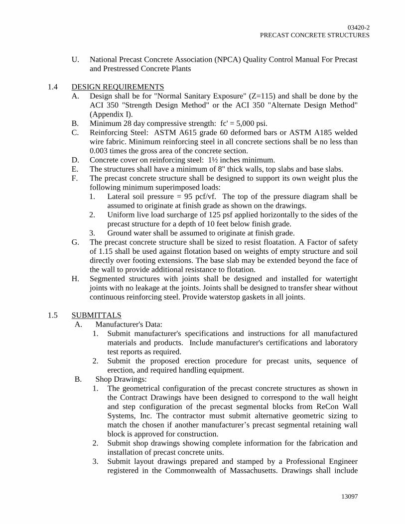
03420-2
PRECAST CONCRETE STRUCTURES
13097
U. National Precast Concrete Association (NPCA) Quality Control Manual For Precast
and Prestressed Concrete Plants
1.4 DESIGN REQUIREMENTS
A. Design shall be for "Normal Sanitary Exposure" (Z=115) and shall be done by the
ACI 350 "Strength Design Method" or the ACI 350 "Alternate Design Method"
(Appendix I).
B. Minimum 28 day compressive strength: fc' = 5,000 psi.
C. Reinforcing Steel: ASTM A615 grade 60 deformed bars or ASTM A185 welded
wire fabric. Minimum reinforcing steel in all concrete sections shall be no less than
0.003 times the gross area of the concrete section.
D. Concrete cover on reinforcing steel: 1½ inches minimum.
E. The structures shall have a minimum of 8" thick walls, top slabs and base slabs.
F. The precast concrete structure shall be designed to support its own weight plus the
following minimum superimposed loads:
1. Lateral soil pressure = 95 pcf/vf. The top of the pressure diagram shall be
assumed to originate at finish grade as shown on the drawings.
2. Uniform live load surcharge of 125 psf applied horizontally to the sides of the
precast structure for a depth of 10 feet below finish grade.
3. Ground water shall be assumed to originate at finish grade.
G. The precast concrete structure shall be sized to resist floatation. A Factor of safety
of 1.15 shall be used against flotation based on weights of empty structure and soil
directly over footing extensions. The base slab may be extended beyond the face of
the wall to provide additional resistance to flotation.
H. Segmented structures with joints shall be designed and installed for watertight
joints with no leakage at the joints. Joints shall be designed to transfer shear without
continuous reinforcing steel. Provide waterstop gaskets in all joints.
1.5 SUBMITTALS
A. Manufacturer's Data:
1. Submit manufacturer's specifications and instructions for all manufactured
materials and products. Include manufacturer's certifications and laboratory
test reports as required.
2. Submit the proposed erection procedure for precast units, sequence of
erection, and required handling equipment.
B. Shop Drawings:
1. The geometrical configuration of the precast concrete structures as shown in
the Contract Drawings have been designed to correspond to the wall height
and step configuration of the precast segmental blocks from ReCon Wall
Systems, Inc. The contractor must submit alternative geometric sizing to
match the chosen if another manufacturer’s precast segmental retaining wall
block is approved for construction.
2. Submit shop drawings showing complete information for the fabrication and
installation of precast concrete units.
3. Submit layout drawings prepared and stamped by a Professional Engineer
registered in the Commonwealth of Massachusetts. Drawings shall include

03420-3
PRECAST CONCRETE STRUCTURES
13097
member dimensions and cross sections, locations, sizes, types and details of
reinforcement, including special reinforcement and lifting devices necessary
for handling and erection.
4. Submit layout, dimensions, and identification of each precast unit
corresponding to the sequence and procedure of installation. Indicate welded
connections by AWS standard symbols. Provide details for all inserts,
connections, and joints.
5. Submit location and details of anchorage devices that are to be embedded in
the precast concrete sections or other concrete construction. Furnish
templates if required for accurate placement.
6. Submit concrete mix design including product data for concrete accessories
and waterproofing materials.
1.6 QUALITY ASSURANCE
A. The manufacture shall exhibit satisfactory performance on projects of similar
magnitude under similar or equal service conditions for a period not less than five
(5) years.
1.7 WARRANTY
A. The Precast Concrete manufacturer shall guarantee all precast concrete members
against excessive movement after erection, causing separation of joints, cracking or
misalignment of adjacent units. The manufacturer shall also guarantee all joints
between concrete sections against leakage and all members against infiltration of
water through the concrete. The manufacturer shall repair or replace all defective
work for a period of one year after the Date of Substantial Completion at no
additional cost to the Owner.
1.8 DELIVERY, STORAGE AND HANDLING
A. All materials shall be inspected by the General Contractor for shipping damage at
the time of delivery. All damaged materials shall be replaced by the Contractor at
no additional cost to the Owner.
B. Store precast concrete units at the project site to ensure against cracking, distortion,
staining, or other physical damage, and so that markings are visible. Lift and
support units at the designated lift points only.
C. All precast concrete units shall be placed on supports such that they are stored off
the ground.
1.9 JOB CONDITIONS
A. General Contractor shall examine all parts of the supporting structure and the
conditions under which the precast concrete work is to be erected. All conditions
that are not satisfactory for the successful installation of the precast structure shall
be repaired. Do not proceed with the installation until unsatisfactory conditions
have been corrected.
B. Contractor shall ensure that all embedded items in the supporting structure have
been properly installed and in the correct locations.
PART 2 - PRODUCTS

03420-4
PRECAST CONCRETE STRUCTURES
13097
2.1 MANUFACTURERS.]
A. Superior Concrete Company, Inc. (Oldcastle Precast), Auburn, ME
B. American Concrete Industries, Auburn, ME
C. American Concrete Industries, Bangor, ME
D. Concrete Systems, Inc, Hudson, NH
E. Scituate Ray Precast Concrete Products, Marshfield, MA
F. Oldcastle Precast-Rotondo, Rehobath, MA
G. Oldcastle Precast, Inc, Avon, CT
H. Or equivalent.
2.2 MATERIALS
A. All precast units shall be constructed with tongue and grooved joints and of shapes
and sizes as shown on the Drawings.
B. Concrete mix design shall conform to the following:
a. Minimum compressive strength of concrete at 28 days (f'c) = 5000 psi.
b. Maximum water/cement ratio = 0.45
c. Cement for all units shall be Type II Portland cement conforming to ASTM
C150.
d. Entrained air content of concrete: 6% ± 1.5%. Air entrainment admixture
shall conform to ASTM C260.
e. Coarse and fine aggregates shall conform to ASTM C33
f. Potable water shall conform to ASTM C1602.
C. Reinforcing steel shall be grade 60 deformed bars and conform to ASTM A615.
F. Precast section joints: Install solid, continuous butyl rubber gaskets in all joints to
achieve watertight joints. Gaskets shall conform to ASTM C990. Kent Seal No. 2
by Hamilton Kent or equal.
G. Inserts: Install stainless steel inserts as required for lifting, connections, etc
PART 3 - EXECUTION
3.1 FABRICATION AND PLACING REINFORCEMENT
A. Detailing and fabrication of reinforcement shall conform to the CRSI Code of
Standard Practice unless otherwise indicated on the Drawings.
B. Reinforcing steel bars shall be clean and free from loose mill scale and rust and
from coatings that reduce bond.
C. Place reinforcement of structural members on accessory bolsters and chairs
Accessories shall be stainless steel or have plastic tips.
D. All reinforcing shall have adequate concrete cover as indicated herein.
3.2 PRODUCTION, CURING, AND STORAGE
A. Production, curing and storage of the precast units shall conform to the provisions
of the NPCA "Quality Control Manual For Precast and Prestressed Concrete
Plants".
B. Each precast concrete unit shall be an integral placement without any construction
or cold joints. Floor slabs shall be an integral placement with the bottom wall
section.

03420-5
PRECAST CONCRETE STRUCTURES
13097
C. Structures shall be fabricated from the minimum number of precast sections in
order to minimize the number of joints.
D. All surfaces shall be cast with a smooth form finish (SFF): The concrete surface
shall be of uniform color, texture and free of all irregularities. The arrangement of
the facing material shall be orderly and symmetrical, with the number of seams kept
to the minimum. Material with raised grain, torn surfaces, worn edges, patches,
dents, or other defects which will impair the texture of the concrete surface shall not
be used. Remove fins and other surface projections flush by grinding and/or
rubbing.
3.3 HANDLING, AND TRANSPORTATION
A. All precast concrete units shall be lifted using designated pick points and lifting
inserts. Extreme caution shall be exercised so as not to damage the units during
handling.
B. Precast concrete units shall be properly supported during transportation to minimize
damage. Do not transport units until they have been cured for a minimum of 5 days
or have reached 75% of their 28 day design strength.
3.4 REPAIR OF UNITS AT PROJECT SITE
A. Contractor shall repair all damaged, cracked, or chipped units in accordance with
Specification Section 03346 "Concrete, Finishing, Curing and Repairs". All units
that are damaged beyond repair as determined by the Engineer shall be removed
from the project site and replaced at no additional cost to the Owner.
3.5 ERECTION
A. Install all precast structures level and plumb to the elevations and in the locations
shown on the Drawings. All units shall be lifted using designated lift point and
inserts in accordance with the written instructions from the Precast Concrete
Structure supplier.
B. Installation Tolerances: Install precast units without exceeding the following
tolerance limits:
1. Variations from Plumb: 1/4" in any 20' run or story height ; 1/2" total in any
40' or longer run.
2. Variations from Level or Elevation: 1/4" in any 20' run; 1/2" in any 40' run;
total plus or minus 1/2" at any location.
3. Variation from Theoretical Position in Plan: Plus or minus 1/4" maximum at
any location.
4. Offsets in Alignment of Adjacent Members at Any Joint: 1/16" in any 10'
run: 1/4" maximum.
C. After erection is complete, all surface damages to the precast concrete units shall be
properly repaired by the Contractor in accordance with Specification Section 03346
"Concrete, Finishing, Curing and Repairs". All lifting inserts and holes shall be
patched after final installation.
END OF SECTION

13097
03421-1
SECTION 03421
PRECAST CONCRETE RETAINING WALL
PART 1 - GENERAL
1.1 SECTION INCLUDES
A. Precast Segmental Modular Block Retaining Wall Units
1.2 RELATED SECTIONS
A. Section 01340 - Submittals
B. Section 02200 - Earthwork
1.3 REFERENCES
A. ASTM C-1372 Specifications for Segmental Retaining Wall Units
B. ASTM C-94 Standard Specification for Ready Mix Concrete
C. ASTM C-172 Standard Specification for Sampling Freshly Mixed Concrete
D. ACI 308-92 - Revised 1992 - Standard Practice for Curing Concrete
E. ACI 318-99 - Building Code Requirements for Reinforced Concrete
F. ASTM A82-97a - Specification for Steel Wire, Plain, for Concrete Reinforcement
G. A185-97 - Specification for Steel Welded Wire Fabric, Plain for Concrete
Reinforcement
H. ASTM A615/A615M-00 - Specification for Deformed and Plain Billet - Steel Bars
for Concrete Reinforcement
I. ASTM C33-999 - Specification for Concrete Aggregates
J. ASTM C150-999 - Specification Portland Cement
K. ASTM C260-00 - Specification for Air Entraining Admixtures for Concrete
L. ASTM C309-98a - Specification for Liquid Membrane-Forming Compounds for
Curing Concrete
M. ASTM C494/C494M-99a - Specification for Chemical Admixtures for Concrete
1.4 DESIGN REQUIREMENTS
A. Minimum 28 day compressive strength: fc' = 4,000 psi.
B. Reinforcing Steel: ASTM A615 grade 60 deformed bars.
C. Concrete shall have air entrainment by volume (as measured in the plastic state in
accordance with ASTM C172) of 5.5 – 8.5 percent, or in conformity with ASTM
C94 (Table 1 and Section 7), latest revision.
1.5 SUBMITTALS
A. Manufacturer's Data:
1. Submit manufacturer's specifications and installation instructions for all
manufactured materials and products.
2. Contractor shall submit the proposed erection procedure for precast units,
sequence of erection, and required handling equipment.
B. Shop Drawings:

03421-2
PRECAST CONCRETE RETAINING WALL
13097
1. Submit shop drawings showing complete information for the fabrication and
installation of precast concrete units.
2. Submit member dimensions and cross section, location, size, type and details
of reinforcement, including special reinforcement and lifting devices
necessary for handling and erection, joints.
3. The contract drawings have been designed to utilize precast concrete retaining
wall from ReCon Wall Systems, Inc. If alternative blocks are chosen and
approved by the Engineer, submit layout, dimensions, and identification of
each precast unit corresponding to the sequence and procedure of installation.
1.6 QUALITY ASSURANCE
A. The manufacturer shall exhibit satisfactory performance on projects of similar
magnitude under similar or equal service conditions for a period of not less than
five (5) year. Submit past job list with Owner contact information.
1.7 DELIVERY, STORAGE AND HANDLING
A. Deliver precast concrete units to the project site in such quantities and at such times
as will assure the continuity of the installation.
B. Store units at the project site to ensure against cracking, distortion, staining, or other
physical damage, and so that markings are visible. Lift and support units at the
designated lift points only.
PART 2 - PRODUCTS
2.1 MANUFACTURERS
1. The contract drawings have been designed to utilize precast concrete retaining wall from
ReCon Wall Systems, Inc. Alternative blocks are acceptable, however the contractor is
responsible for adjusting geometric parameters of the design plans to accommodate that
of the proposed block wall manufacturer and provide updated details for the approval of
the Engineer and owner.
2. The following Manufacturers are acceptable:
A. ReCon Wall Systems, Inc.
7600 West 27th St., #229
St Louis Park, MN 55426
(952) 922-0027 Phone
(952) 922-0028 Fax
www.reconwalls.com

03421-3
PRECAST CONCRETE RETAINING WALL
13097
B. MagnumStone
803 – 1625 Manitoba Street
Vancouver, BC, Canada V5Y 0B8
Phone: 604-939-7999
www.magnumstone.com
C. Redi-Rock International
5481 US-31
Charlevoix, MI 49720
Phone: (866) 222-8400
www.redi-rock.com
D. Or Approved Equivalent
2.2 MATERIALS
A. The retaining wall block unit shall be wet-cast, consist of concrete with the average 28-
day compressive strength of no less than 4000 PSI.
B. Concrete shall have air entrainment by volume (as measured in the plastic state in
accordance with ASTM C172) of:
a. 5.5 – 8.5 percent, or In conformity with ASTM C94 (Table 1 and Section 7),
latest revision.
C. Depth of unit should be 24”.
D. Units shall me the following Tolerances:
a. Height: +/- 3/16”
b. Width: +/- 1/2" unless field cut for fitting purposes.
c. Depth: No less than the unit design depth of 24” with the textured face portion of
the block is considered as 4”
E. Unit Face Texture Shall be approved by the Engineer.
PART 3 - EXECUTION
3.1 INSTALLATION
A. First course of units shall be placed in full contact with the crushed stone layer wrapped
in fabric as shown on the Construction Drawings.
B. Check units for level from side-to-side, front to back, and check to maintain unit batter
front-to-back.
C. Place unit faces in contact side to side and avoid any gaps greater than ½”.
D. Fill and compact fill to grade in front of embedded units prior to compaction behind the
wall units.
E. Fill voids between block units with crushed stone.
F. Sweep and clean the top of each course before setting additional courses.
G. Lay each successive course making sure that the bottom recess is in full contact with the
unit locators of the course below. Pull unit forward as far as possible. Backfill and
compact soil behind the units.
H. Check and maintain level and wall batter by use of shims when necessary.

03421-4
PRECAST CONCRETE RETAINING WALL
13097
I. Handle units with proper lifting devices that have been certified for the loads associated
with the weights of the units. Avoid applying forces to the lifting loops in excess of the
normal force associated with the weight of the unit (i.e., avoid applying “shear forces” or
“dynamic loads” from bouncing or swinging of a unit). If the unit is to be transported
over a significant distance in the field, it is recommended that a cable be used, not a
chain.
3.2 CLEANING, REPAIRING AND PROTECTION
A. After erection is complete, any chipped or damaged units and any depressions left
by removal of lifting devices shall be properly repaired by the erector. Also, all
erection dirt incurred during the erection process shall be removed.
END OF SECTION

13097
05500-1
SECTION 05500
METAL FABRICATIONS
PART 1 - GENERAL
1.1 SECTION INCLUDES
A. Aluminum Angles
B. Surface preparation
1.2 PRODUCTS FURNISHED BUT NOT INSTALLED UNDER THIS SECTION
A. Concrete anchors
1.3 RELATED SECTIONS
A. Section 01340 - Submittals
B. Section 03300 - Cast-in-Place Concrete
1.4 REFERENCES
A. This section contains references that are applicable to this Specification Section.
The applicable edition of the indicated references shall be the version that was the
most current at the time of the Advertisement of Bids. If referenced documents have
been discontinued by the issuing organization, references to those documents shall
mean the replacement documents issued or otherwise identified by that organization
or, if there are no replacement documents, the last version of the document before it
was discontinued. Where document dates are given in the following listing,
references to those documents shall mean the specific document version associated
with that date, whether or not the document has been superseded by a version with a
later date, discontinued, or replaced.
B. ASTM B221 - Specification for Aluminum and Aluminum-Alloy Extruded Bars,
Rods, Wire, Profiles and Tubes
C. ASTM B308/B308M - Specification for Aluminum-Alloy 6061-T6 Standard
Structural Profiles
D. Aluminum Association Aluminum Design Manual (2010)
E. Aluminum Association Aluminum Standards And Data (2009)
1.5 SUBMITTALS
A. Submit complete shop drawings showing fabrication, welding, connections,
erection, finishes, materials and dimensions including plans, elevations, sections
and details of all metal fabrications and connections and location of item in
structure. Photocopies of Contract Drawings, in whole or part, will not be accepted
as shop drawings.
B. Submit product data in accordance with the provisions of Section 01340.
C. Submit design computations when required.
1.7 QUALITY ASSURANCE

05500-2
METAL FABRICATIONS
13097
A. Conform to the Aluminum Design Manual for the design, fabrication and erection
of structural aluminum.
1.8 COORDINATION
A. The Contractor shall coordinate with the work of other Sections. Verify at the site
both the dimensions and the work of other trades adjoining items before fabrication
and installation of items herein specified.
B. Furnish to the pertinent trades all items included under this Section that are to be
built into the work of other Sections.
1.9 FIELD MEASUREMENTS
A. Field measurements shall be taken at the site to verify or supplement indicated
dimensions and to insure proper fitting of all items.
B. Templates of channel and tank configuration shall be made for the installation of
grating or checkered plate for the areas to be covered.
1.10 DELIVERY, STORAGE, HANDLING
A. Coordinate delivery of products.
B. Protect products from damage prior to and after installation.
C. Remove damaged material from the site.
PART 2 - PRODUCTS
2.1 ALUMINUM ANGLE
A. Material: Aluminum alloy 6061-T6 (ASTM B209)
B. Finish: Mill
2.3 FASTENERS
A. Concrete anchorage:
1. Epoxy Anchors. ASTM C881. Non-expanding two component epoxy resin
with AISC Type 316 Stainless Steel threaded rod with washer and nut.
a. HIT RE500SD by Hilti Fastening Systems
b. Chemset Capsule Series by Ramset Fastening Systems
c. AC100 Plus by Powers Fasteners
d. Or equivalent.
2. Expansion Anchors - Stainless steel AISI Type 316 for galvanized and
aluminum fabrications; cadmium plated for painted steel fabrications.
a. Kwik-Bolt III by Hilti Fastening Systems or
b. Tru Bolt Stud Anchor by Ramset Fastening System
c. Power Stud by Powers Fasteners
d. Or equivalent.
3. Anchor Rods
a. Material: ASTM F1554 Grade 55
b. Finish: Hot-Dipped Galvanized ASTM A153
B. Bolted Joints:
1. Aluminum Fabrications: Stainless Steel ASTM F593 & F594 Alloy Group 2
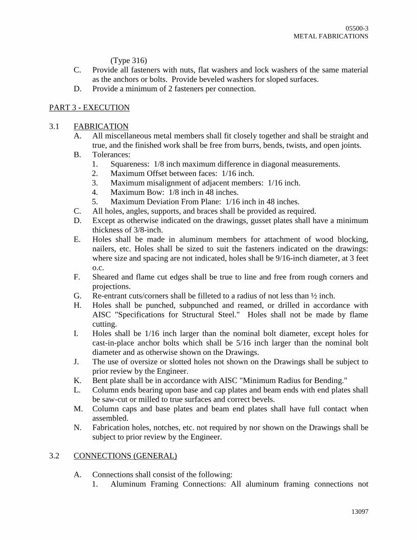
05500-3
METAL FABRICATIONS
13097
(Type 316)
C. Provide all fasteners with nuts, flat washers and lock washers of the same material
as the anchors or bolts. Provide beveled washers for sloped surfaces.
D. Provide a minimum of 2 fasteners per connection.
PART 3 - EXECUTION
3.1 FABRICATION
A. All miscellaneous metal members shall fit closely together and shall be straight and
true, and the finished work shall be free from burrs, bends, twists, and open joints.
B. Tolerances:
1. Squareness: 1/8 inch maximum difference in diagonal measurements.
2. Maximum Offset between faces: 1/16 inch.
3. Maximum misalignment of adjacent members: 1/16 inch.
4. Maximum Bow: 1/8 inch in 48 inches.
5. Maximum Deviation From Plane: 1/16 inch in 48 inches.
C. All holes, angles, supports, and braces shall be provided as required.
D. Except as otherwise indicated on the drawings, gusset plates shall have a minimum
thickness of 3/8-inch.
E. Holes shall be made in aluminum members for attachment of wood blocking,
nailers, etc. Holes shall be sized to suit the fasteners indicated on the drawings:
where size and spacing are not indicated, holes shall be 9/16-inch diameter, at 3 feet
o.c.
F. Sheared and flame cut edges shall be true to line and free from rough corners and
projections.
G. Re-entrant cuts/corners shall be filleted to a radius of not less than ½ inch.
H. Holes shall be punched, subpunched and reamed, or drilled in accordance with
AISC "Specifications for Structural Steel." Holes shall not be made by flame
cutting.
I. Holes shall be 1/16 inch larger than the nominal bolt diameter, except holes for
cast-in-place anchor bolts which shall be 5/16 inch larger than the nominal bolt
diameter and as otherwise shown on the Drawings.
J. The use of oversize or slotted holes not shown on the Drawings shall be subject to
prior review by the Engineer.
K. Bent plate shall be in accordance with AISC "Minimum Radius for Bending."
L. Column ends bearing upon base and cap plates and beam ends with end plates shall
be saw-cut or milled to true surfaces and correct bevels.
M. Column caps and base plates and beam end plates shall have full contact when
assembled.
N. Fabrication holes, notches, etc. not required by nor shown on the Drawings shall be
subject to prior review by the Engineer.
3.2 CONNECTIONS (GENERAL)
A. Connections shall consist of the following:
1. Aluminum Framing Connections: All aluminum framing connections not

05500-4
METAL FABRICATIONS
13097
detailed on the Drawings shall be bolted connections designed by the
fabricator subject to the provisions of the design drawings, specifications and
the referenced Aluminum Design Manual. All connections shall consist of a
minimum of 2 – L3x3x1/4 angles with 2 – ¾ inch diameter AISI Type 316
bolts between each angle and framing member.
B. At the time of connecting, all bearing surfaces shall be free from loose or
nonadherent rust, loose mill scale, oil, grease, dirt, mud, and any foreign matter,
coating, or defect that adversely affects the connection.
C. At the time of connecting, all faying surfaces at bolted connections shall be free
from loose or nonadherent rust, loose mill scale, oil, grease, dirt, mud, and any
foreign matter, coating, or defect that adversely affects the connection.
3.3 CLEANING
A. Clean surfaces of all work of this section as well as the areas in the vicinity.
3.4 PROTECTION
A. Protect installed work from:
1. Splatter or debris from adjacent construction.
2. Excess construction loading and use.
END OF SECTION

13097
06100-1
SECTION 06100
ROUGH CARPENTRY
PART 1 - GENERAL
1.1 SECTION INCLUDES
A. Temporary enclosures.
B. All rough lumber, including wood nailers, posts, plates, blocking, strapping, and
lumber bases.
C. Rough hardware, such as nails, bolts, screws, clips, as required to install rough
carpentry work.
D. Lumber Preservatives.
1.2 RELATED SECTIONS
A. Section 01340 – Submittals
B. Section 03300 – Cast-in-Place Concrete
C. Section 05500 – Metal Fabrications
1.3 REFERENCE
A. Standard pressure process shall conform to Federal Specification TT-W-573.
1.4 QUALITY ASSURANCE
A. All lumber except as otherwise specified herein shall:
1. Be new, dressed 4 sides (S4S), clean, and free from warping and other
defects.
2. Conform to U. S. Department of Commerce Simplified Practice
Recommendations R-l6 for sizes and use Classifications.
3. Have a moisture content not exceeding l9 percent when delivered to the
project.
4. National Forest Products Association - "National Design Specification for
Wood Construction - 2005 including Design Values for Wood Construction".
B. Plywood shall conform to American Plywood Association APA Grade Trademark
and Product Standard PS-1.
1.5 SUBMITTALS
A. Submit product data under provision of Section 01340.
B. The treating plant shall furnish a notarized certificate that all pertinent details of
these specifications have been met.
C. Submit lumber species and grade.
D. Submit hardware indicated on the Drawings.
1.6 DELIVERY, STORAGE AND HANDLING
A. Store all materials in an elevated dry location, protected by waterproof
coverings. Do not store within the building until masonry, concrete, and other such
wet work has been completed and allowed to dry.

06100-2
ROUGH CARPENTRY
13097
PART 2 - PRODUCTS
2.1 MANUFACTURERS
A. Wolmanized Pressure-Treated Lumber
1. Hickson Corp.
2. Hoover Treated Wood Products
3. Koppers
2. Or equal
2.2 LUMBER TREATMENTS
A. Pressure Preservative Treatments: All dimension lumber, wood blocking and nailers
which will be embedded or in contact with concrete and masonry, and all nailers
which will be concealed by roofing and flashing, shall be treated with ACQ (Type
D). The minimum retention shall be 0.25 pounds of preservative per cubic foot of
wood.
B. Brush Preservative Treatment: Brush coat all end cuts after cutting with ACQ or
equal. Apply in two heavy coats on all surfaces prior to installation of lumber.
2.3 MATERIALS
A. All dimensional lumber to be used in exterior and bearing walls shall be Spruce-
Pine-Fir No. 2 or better unless indicated otherwise on the Structural Drawings.
B. Nailers, blocking, equipment bases, and all other lumber of actual l-l/2 inches or
greater thickness - Douglas fir, spruce, pine, number two (2) or better, unless
indicated otherwise on the Structural Drawings.
C. Furring and other lumber less than l-l/2 inches in thickness - No. 2 spruce or
Douglas fir.
2.4 ROUGH HARDWARE
A. Framing anchors, nail plates and other fasteners as indicated on Drawings.
B. Expansion anchor and anchor bolts shall be as shown on the Drawings and as
specified in Section 05500. For other non-specified conditions the following
minimums shall apply:
1. Other nailers and blocking in excess of 7/8 inch thick - 3/4 inch diameter
galvanized steel anchor bolts or expansion bolts, as applicable.
2. Furring, strapping and blocking 7/8 inch thick or less attached to concrete or
masonry- 5/16 inch diameter galvanized steel anchor bolts or expansion bolts.
3. Secure other non-specified lumber with galvanized steel fasteners, of a type
most suitable for the application.
C. Hardware and fasteners in contact with pressure treated lumber shall be stainless
steel.
PART 3 - EXECUTION
3.1 TEMPORARY BRACING
A. Provide and maintain, until such time as permanently built into the structure, all
temporary bracing for walls, door frames, sills, and other work requiring bracing

06100-3
ROUGH CARPENTRY
13097
and which is not specified as being provided under other SECTIONS of the
specifications.
3.2 PROTECTION
A. Do such work as is necessary to cover and protect all finishes and other work from
damage during construction.
3.3 NAILERS AND BLOCKING
A. Fasten nailers and blocking to concrete and masonry with specified bolts, as shown
on Drawings. Space bolts not over 32 inches on centers. Stagger lines of bolts on
nailers wider than nominal 3-1/2 inch width. Use not less than two (2) bolts per
piece of nailer length. Counterbore nailers so that nut and ends of bolts are recessed
below top surface. Install wood shims behind nailers and blocking against
masonry, as required, to ensure completely true surface.
END OF SECTION

APPENDIX A
Wooden Pedestrian Bridge Manufacturer’s Drawings

HAWTHORNE BRIDGE INSTRUCTIONS - 16’-24’ LONG MODELS
COMPONENTS – Wood parts (see chart on page 2)

Parts list
16' - 24’ LONG BRIDGES Length of Bridge
16’ 18’ 20’ 22’ 24’ # 2 SQUARE HEAD BIT * 1 1 1 1 1 5/16" X 4" LAG BOLTS W/ WASHERS * 8 8 8 8 8 3" SCREWS * VARIES BY SIZE - SEE BELOW OUTSIDE BEAMS / TRUSS ASSEMBLY A 2 2 2 2 2 INTERIOR BEAM /TRUSS ASSEMBLY(S) A1 VARIES BY WIDTH – SEE BELOW END BOARDS B 2 2 2 2 2 2X4 POSTS - Ends of Bridge C 4 4 4 4 4 2X4 POSTS - Top of Bridge D 4 4 4 4 4 RAILING UPRIGHTS (TOP) E 2 2 2 2 2 RAILING UPRIGHTS (SIDE) F 4 4 4 4 4 UPPER RAILINGS (TOP) G 2 2 2 2 2 UPPER RAILINGS (SIDE) H 4 4 4 4 4 Notched Floorboards (Marked A) I 2 2 2 2 2 Notched Floorboards (Marked B) J 2 2 2 2 2 Notched Floorboards (Marked C) K 2 2 2 2 2 FLOOR BOARDS - not notched L 34 39 44 49 52
CROSS TIES TRUSS SUPPORTS M 2 2 2 2 2
INTERIOR BEAMS
2 - 1/2" DECK SCREWS PER BRIDGE
3" SCREWS PER BRIDGE
WIDTH #
WIDTH 16' 18' 20' 22' 24'
WIDTH 16' 18' 20' 22' 24'
27" 0
27" 136 156 176 196 208
27" 92 96 96 96 96
36" (3') 1
36" (3') 204 234 264 294 312
36" (3') 100 106 106 106 106
48" (4') 1
48" (4') 204 234 264 294 312
48" (4') 100 106 106 106 106
60" (5') 2
60" (5') 272 312 352 392 416
60" (5') 108 116 116 116 116
72" (6') 3
72" (6') 340 390 440 490 520
72" (6') 116 126 126 126 126
NOTE: Image in instructions may not show quantity of components use chart for inventory.
Step 1 – Post and Beams Assembly
Lay out and identify all the wooden components for the Railings using the chart and drawings.
NOTE: You want to attach the railings to the beams on a level flat surface, with the beams
laying down. Do not attach posts while the beams are standing up.
If your bridge is 27” wide, you will not have an interior beam. Wider bridges have from 1 to 3
interior beams. The two outside beams can be identified because they have marking on them
to identify where the posts will be attached. Interior beams have no such markings. The two

outside beams are interchangeable (no left or right
side beam). All the interior beams are marked on one
end. Face the beams so the markings face the same
way as exterior beams.
All the 2x4 posts are not identical. (See the drawing at
right.) You will position so that the tops of the posts will follow the contour of the bridge.
Attaching the end posts (C) – Use the markings to
insure that the posts will be plumb. Using the
markings will also insure that the posts overhang
the ends of the beam by 1 ½”. Attach with 2
screws at this time. The bottom of the post will
be aligned with the bottom point of the beams.
DO NOT attach Lag Bolt at this time.
Attaching the middle posts (D) – Note that the
side of the posts will be a t a right angle with the
top part of the beam. Use the markings on the
beam to insure that the Posts are positioned.
(You can also use a quick square to insure the 90
degree angle.) Attach to beams with 4 screws,
and lag bolt using the predrilled holes in the post.
Finishing attaching all 8 posts (4 per beam).

Step 2 – Railing Assembly
Building the railings can be done either with the beams lying down or standing up, whichever is
easier for you. Layout the center railing components - top handrail (G) and the upright 2x4 (E)
support. Set the top hand rail on top of the posts, and position one side at the point where the
cut slopes off at the top of the post.
Attach to one post using one screw.
Be sure that the handrail is centered
on the post. Then take the upright
support and attach with one screw on
the same side as shown at the right.
Be sure that the upright is snug against
the posts and up tight against the
bottom of the top hand rail.
Then go to the other end of the hand rail and attach the hand rail and uprights to the other
post in the same way. The connection should be snug, but if not, pull the posts together. The
hand rail must meet at the point on the posts.
Nest, attach the hand rails for the side railings in the same way, attaching the handrail first on
the upper post. Then attach the upright to the top post, and then to the end posts. Finally
attach the with two screws through the hand rail into the top of the end posts. The hand rail
will extend beyond the end posts.
Once the railings are attached to the posts, finishing by attaching the top rails to the uprights
with screws. There will be a total of 15 screws used to attach the top handrail to the posts and
uprights as shown below. Repeart this for the other beam.
Completed Beam / Truss and
Railing Assembly.
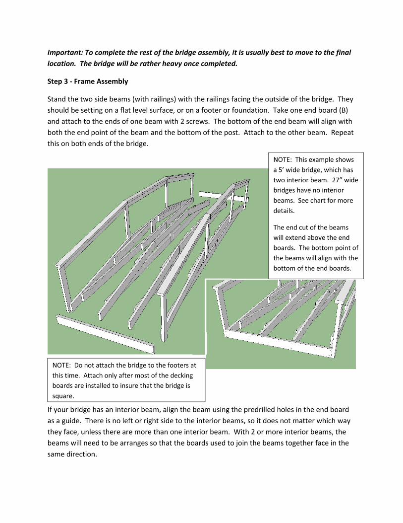
Important: To complete the rest of the bridge assembly, it is usually best to move to the final
location. The bridge will be rather heavy once completed.
Step 3 - Frame Assembly
Stand the two side beams (with railings) with the railings facing the outside of the bridge. They
should be setting on a flat level surface, or on a footer or foundation. Take one end board (B)
and attach to the ends of one beam with 2 screws. The bottom of the end beam will align with
both the end point of the beam and the bottom of the post. Attach to the other beam. Repeat
this on both ends of the bridge.
If your bridge has an interior beam, align the beam using the predrilled holes in the end board
as a guide. There is no left or right side to the interior beams, so it does not matter which way
they face, unless there are more than one interior beam. With 2 or more interior beams, the
beams will need to be arranges so that the boards used to join the beams together face in the
same direction.
NOTE: This example shows
a 5’ wide bridge, which has
two interior beam. 27” wide
bridges have no interior
beams. See chart for more
details.
The end cut of the beams
will extend above the end
boards. The bottom point of
the beams will align with the
bottom of the end boards.
NOTE: Do not attach the bridge to the footers at
this time. Attach only after most of the decking
boards are installed to insure that the bridge is
square.

After the two end boards are installed, attach the end
posts to the end boards with the lag bolt and two screws in
the predrilled holes.
Locate the Cross ties – Depending on the length of the
bridge these will be either 2x6’s or 2x8’s.
Install the Cross ties on either side of the board
that runs vertically from the truss to the beam.
The ends of the boards have predrilled holes.
The ends of the cross ties will be flush with the
upright truss board. If interior beams are used,
there are no predrilled holes, but you should
attach them to the interior trusses with 2
screws per connection.
Completed Bridge Frame with Railings

Step 4 – Bridge Decking Installation
Be careful when finishing assembly if the bridge will be positioned over an area that is
inaccessible from below. Instructions show installing the top part of the bridge decking first.
If it is safer to assemble the sides first reverse the next two steps and work from the
completed bridge decking to finish the top decking.
(Note: images below do not show truss assembly for clarity)
Top Decking – Locate the two
notched decking boards that are
marked “A”. Position them as shown
at right. Make sure that one side is
tight against the post, and attach
one side with two screws. Then go
to the other side and attach with
two screws. If the board is not tight
against the post, pull in (or push out)
on the post before attaching. Attach
the other A board in the same way.
If your bridge has interior beams, attach with 2 screws using the predrilled holes as a guide to
center the beam.
Next attach decking boards between
these two boards. The number of
boards will vary by the length of the
bridge. Be sure that the ends of the
boards are aligned with the first
boards (they will also be aligned
with the outside of the posts
(Overhanging the beams by about 1
1/2”. Position the boards without
attaching them and arrange so that the gap between the boards is equal (about 1/8”). Once
properly spaced, attach with 2 screws over each beam.
NOTE: If you are attaching the bridge to a footer or other
support, do so before completing the decking boards at the
ends of the bridge. Attachments are best made using metal L
brackets (Not included). Using 3” screws (not included) to
attach the L bracket to the outside beams as shown at right ,
and screws (wood foundation supports) or wedge bolts (or
other anchoring means to attach to concrete footers). Image
at left shows a generic L bracket.

Side Decking – Locate Notched boards marked B and C. Installation is similar to the steps for
the top deck boards. Boards marked B are
positioned against the top posts, and those
marked C attach to the end of the bridge (Slide the
board in from the inside of the bridge and be sure
it is tight against the posts.
Attach using 2 screws per beam, using the pre
drilled holes.
Position remaining decking boards (without
notches) by laying them out first, and spacing
them so the gap between each board is about the
same. Be sure also that they aligh with the other
boards (overhanging the beam by about 1 ½”.
Your new bridge is now complete.

APPENDIX B
Soil Samples


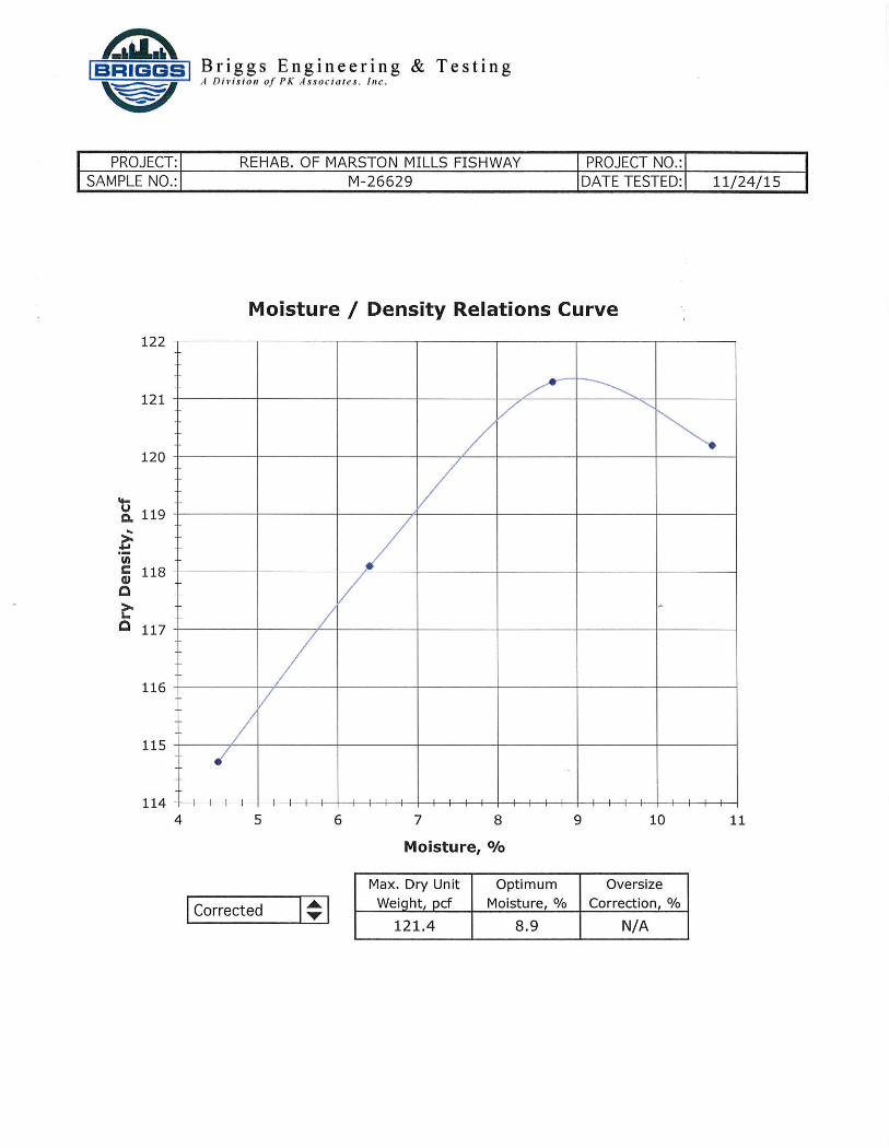
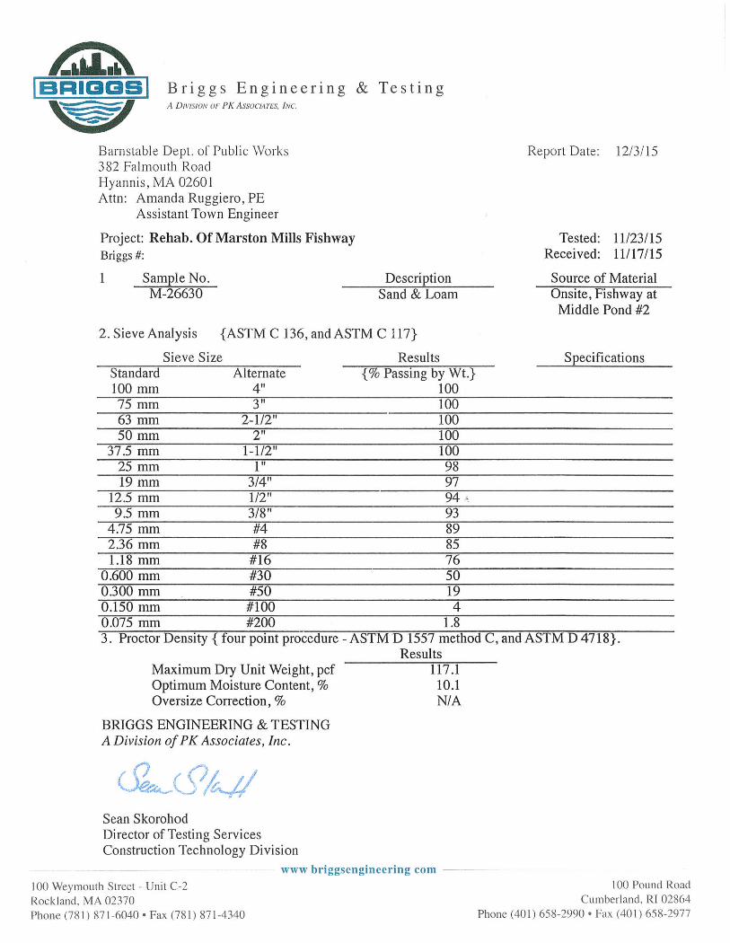


APPENDIX C
Order of Conditions