Technical Specification MEF 10.2 Ethernet Services ... · 13/06/2002 · without notice and he...
65
MEF 10.2 © The Metro Ethernet Forum 2009. Any reproduction of this document, or any portion thereof, shall contain the following statement: "Reproduced with permission of the Metro Ethernet Forum." No user of this document is authorized to modify any of the information contained herein. Technical Specification MEF 10.2 Ethernet Services Attributes Phase 2 27 October 2009
Transcript of Technical Specification MEF 10.2 Ethernet Services ... · 13/06/2002 · without notice and he...
MEF 10.2 © The Metro Ethernet Forum 2009. Any reproduction of this document, or any portion thereof, shall contain the following statement: "Reproduced with permission of the Metro Ethernet Forum." No user of this document is authorized to modify any of the information contained herein.
Technical Specification
MEF 10.2
Ethernet Services Attributes Phase 2
27 October 2009

MEF 10.2 © The Metro Ethernet Forum 2009. Any reproduction of this document, or any portion thereof, shall contain the following statement: "Reproduced with permission of the Metro Ethernet Forum." No user of this document is authorized to modify any of the information contained herein.
Disclaimer
The information in this publication is freely available for reproduction and use by any recipient and is believed to be accurate as of its publication date. Such information is subject to change without notice and the Metro Ethernet Forum (MEF) is not responsible for any errors. The MEF does not assume responsibility to update or correct any information in this publication. No representation or warranty, expressed or implied, is made by the MEF concerning the completeness, accuracy, or applicability of any information contained herein and no liability of any kind shall be assumed by the MEF as a result of reliance upon such information.
The information contained herein is intended to be used without modification by the recipient or user of this document. The MEF is not responsible or liable for any modifications to this document made by any other party.
The receipt or any use of this document or its contents does not in any way create, by implication or otherwise:
a) any express or implied license or right to or under any patent, copyright, trademark or trade secret rights held or claimed by any MEF member company which are or may be associated with the ideas, techniques, concepts or expressions contained herein; nor
b) any warranty or representation that any MEF member companies will announce any product(s) and/or service(s) related thereto, or if such announcements are made, that such announced product(s) and/or service(s) embody any or all of the ideas, technologies, or concepts contained herein; nor
c) any form of relationship between any MEF member companies and the recipient or user of this document.
Implementation or use of specific Metro Ethernet standards or recommendations and MEF specifications will be voluntary, and no company shall be obliged to implement them by virtue of participation in the Metro Ethernet Forum. The MEF is a non-profit international organization accelerating industry cooperation on Metro Ethernet technology. The MEF does not, expressly or otherwise, endorse or promote any specific products or services.
© The Metro Ethernet Forum 2009. All Rights Reserved.
Ethernet Services Attributes Phase 2
MEF 10.2 © The Metro Ethernet Forum 2009. Any reproduction of this document, or any portion thereof, shall contain the following statement: "Reproduced with permission of the Metro Ethernet Forum." No user of this document is authorized to modify any of the information contained herein.
Page i
Table of Contents
1. Abstract ................................................................................................................................ 1
2. Terminology......................................................................................................................... 1
3. Scope..................................................................................................................................... 5
4. Compliance Levels .............................................................................................................. 6
5. Introduction ......................................................................................................................... 6
6. Ethernet Virtual Connection Service Attributes ............................................................. 7 6.1 Ethernet Virtual Connection Type Service Attribute ........................................................ 8
6.1.1 Point-to-Point EVC ................................................................................................................. 8 6.1.2 Multipoint EVCs ..................................................................................................................... 8
6.1.2.1 Multipoint-to-Multipoint EVC ............................................................................................. 8 6.1.2.2 Rooted-Multipoint EVC ....................................................................................................... 9
6.2 EVC ID Service Attribute.................................................................................................. 9 6.3 UNI List Service Attribute .............................................................................................. 10 6.4 Maximum Number of UNIs Service Attribute ................................................................ 10 6.5 Service Frame Delivery Service Attributes ..................................................................... 10
6.5.1 Types of Service Frame ........................................................................................................ 10 6.5.1.1 Unicast Service Frame ...................................................................................................... 10 6.5.1.2 Multicast Service Frame .................................................................................................... 10 6.5.1.3 Broadcast Service Frame .................................................................................................. 10 6.5.1.4 Layer 2 Control Protocol Service Frame .......................................................................... 10 6.5.1.5 Data Service Frame ........................................................................................................... 11
6.5.2 Service Frame Disposition .................................................................................................... 11 6.5.3 Service Frame Transparency ................................................................................................. 12
6.6 CE-VLAN Tag Preservation Service Attributes ............................................................. 12 6.6.1 CE-VLAN ID Preservation Service Attribute ....................................................................... 12 6.6.2 CE-VLAN CoS Preservation Service Attribute .................................................................... 13
6.7 EVC Layer 2 Control Protocol Processing Service Attribute ......................................... 13 6.8 Class of Service Identifier Service Attribute ................................................................... 14
6.8.1 Class of Service Identifier Based on EVC ............................................................................ 14 6.8.2 Class of Service Identifier Based on Priority Code Point Field ............................................ 15 6.8.3 Class of Service Identifier Based on DSCP .......................................................................... 15 6.8.4 Class of Service Identifier Based on Layer 2 Control Protocol ............................................ 15
6.9 EVC Related Performance Service Attributes ................................................................. 15 6.9.1 Frame Delay Performance for a Point-to-Point EVC ............................................................ 16 6.9.2 One-way Frame Delay Performance for an EVC .................................................................. 17 6.9.3 Inter-Frame Delay Variation Performance for a Point-to-Point EVC ................................... 20 6.9.4 Inter-Frame Delay Variation Performance for an EVC ........................................................ 21 6.9.5 One-way Frame Loss Ratio Performance for a Point-to-Point EVC .................................... 24 6.9.6 One-way Frame Loss Ratio Performance for an EVC .......................................................... 24 6.9.7 Availability Performance for a Point-to-Point EVC ............................................................. 25 6.9.8 Availability Performance for a Multipoint EVC ................................................................... 28
6.10 EVC Maximum Transmission Unit Size Service Attribute ............................................. 29
Ethernet Services Attributes Phase 2
MEF 10.2 © The Metro Ethernet Forum 2009. Any reproduction of this document, or any portion thereof, shall contain the following statement: "Reproduced with permission of the Metro Ethernet Forum." No user of this document is authorized to modify any of the information contained herein.
Page ii
7. UNI and EVC per UNI Service Attributes ..................................................................... 29 7.1 UNI Identifier Service Attribute ...................................................................................... 30 7.2 Physical Layer Service Attribute ..................................................................................... 30 7.3 MAC Layer Service Attribute ......................................................................................... 30 7.4 UNI Maximum Transmission Unit Size Service Attribute ............................................. 31 7.5 Service Multiplexing Service Attribute ........................................................................... 31 7.6 Identifying an EVC at the UNI ........................................................................................ 31
7.6.1 Customer Edge VLAN ID ..................................................................................................... 31 7.6.2 UNI EVC ID Service Attribute ............................................................................................. 32
7.7 CE-VLAN ID/EVC Map Service Attribute..................................................................... 32 7.7.1 Basic Concept ........................................................................................................................ 32 7.7.2 CE-VLAN ID Significance ................................................................................................... 33 7.7.3 Describing the Contents of the CE-VLAN ID/EVC Map ..................................................... 34
7.8 Maximum Number of EVCs Service Attribute ............................................................... 34 7.9 Bundling Service Attribute .............................................................................................. 34 7.10 All to One Bundling Service Attribute ............................................................................ 35 7.11 Bandwidth Profiles Service Attributes ............................................................................ 36
7.11.1 Standard Bandwidth Profile Parameters and Algorithm ....................................................... 36 7.11.2 Ingress Bandwidth Profiles Service Attributes ..................................................................... 39
7.11.2.1 Ingress Bandwidth Profile per Ingress UNI Service Attribute .......................................... 39 7.11.2.2 Ingress Bandwidth Profile per EVC Service Attribute ...................................................... 39 7.11.2.3 Ingress Bandwidth Profile per Class of Service Identifier Service Attribute .................... 40 7.11.2.4 Simultaneous Application of the Ingress Bandwidth Profile Application Models ............. 40 7.11.2.5 Service Frame Disposition ................................................................................................ 41
7.11.3 Egress Bandwidth Profiles Service Attributes ...................................................................... 41 7.11.3.1 Egress Bandwidth Profile per Egress UNI Service Attribute ............................................ 42 7.11.3.2 Egress Bandwidth Profile per EVC Service Attribute ....................................................... 43 7.11.3.3 Egress Bandwidth Profile per Class of Service Identifier Service Attribute ..................... 44 7.11.3.4 Simultaneous Application of the Egress Bandwidth Profile Application Models .............. 44
7.12 Security ............................................................................................................................ 44 7.13 UNI Layer 2 Control Protocol Processing Service Attribute .......................................... 44
7.13.1 Discard .................................................................................................................................. 44 7.13.2 Peer ........................................................................................................................................ 45 7.13.3 Pass to EVC ........................................................................................................................... 45 7.13.4 Peer and Pass to EVC ............................................................................................................ 45
8. Ethernet Service Framework ........................................................................................... 45 8.1 Ethernet Service Types .................................................................................................... 46 8.2 Service Attributes ............................................................................................................ 46 8.3 Service Attribute Parameters ........................................................................................... 46 8.4 Ethernet Service Framework Summary ........................................................................... 47
9. References .......................................................................................................................... 49
10. Appendix (Informative) .................................................................................................... 50 10.1 CE-VLAN ID Preservation Service Attribute ................................................................. 51
10.1.1 CE-VLAN ID Preservation = Yes ......................................................................................... 51 10.1.2 CE-VLAN ID Preservation = No .......................................................................................... 52
10.2 Examples of the Use of the CE-VLAN ID/EVC Map and EVCs ................................... 53
Ethernet Services Attributes Phase 2
MEF 10.2 © The Metro Ethernet Forum 2009. Any reproduction of this document, or any portion thereof, shall contain the following statement: "Reproduced with permission of the Metro Ethernet Forum." No user of this document is authorized to modify any of the information contained herein.
Page iii
10.2.1 Untagged UNIs ...................................................................................................................... 53 10.2.2 Use of Rooted-Multipoint EVC ............................................................................................ 54 10.2.3 Redundant Higher Layer Service Access .............................................................................. 55
10.3 Traffic Shaping ................................................................................................................ 55 10.4 Examples of Availability Metrics for Multipoint EVCs ................................................. 57
10.4.1 UNI-oriented Availability Example ...................................................................................... 58 10.4.2 EVC-oriented Availability Example ..................................................................................... 59
List of Figures
Figure 1 – Ethernet Services Model ................................................................................................ 7 Figure 2 – Point-to-Point EVCs ...................................................................................................... 8 Figure 3 – Multipoint-to-Multipoint EVC ...................................................................................... 9 Figure 4 – Rooted-Multipoint EVC ................................................................................................ 9 Figure 5 - Frame Delay for Service Frame ................................................................................... 17 Figure 6 – Inter-Frame Delay Variation Definition ...................................................................... 22 Figure 7 – Examples of the Calculation of ( )kSI ........................................................................ 27 Figure 8 – Example of Service Multiplexing on UNI A ............................................................... 31 Figure 9 – Example of a CE-VLAN ID/EVC Map ....................................................................... 33 Figure 10 – Example of CE-VLAN ID/EVC Maps at Two UNIs ................................................ 34 Figure 11 – Example of Bundling ................................................................................................. 35 Figure 12 – Example of a Simple Description of Bundling .......................................................... 35 Figure 13 – The Bandwidth Profile Algorithm ............................................................................. 38 Figure 14 – Ingress Bandwidth Profile per Ingress UNI .............................................................. 39 Figure 15 – Ingress Bandwidth Profile per EVC .......................................................................... 40 Figure 16 – Ingress Bandwidth Profile per Class of Service Identifier ........................................ 40 Figure 17 – Egress Bandwidth Profile per Egress UNI ................................................................ 43 Figure 18 – Egress Bandwidth Profile per EVC ........................................................................... 43 Figure 19 – Ethernet Service Framework ..................................................................................... 46 Figure 20 – CE-VLAN ID/EVC Map Notation ............................................................................ 51 Figure 21 – Example 1: CE-VLAN ID Preservation = Yes with All to One Bundling ................ 51 Figure 22 – Example 2: CE-VLAN ID Preservation = Yes with Bundling on EVC2.................. 51 Figure 23 – CE-VLAN ID/EVC Map Notation ............................................................................ 52 Figure 24 – Example 3: CE-VLAN ID Preservation = No ........................................................... 53 Figure 25 – Untagged UNIs .......................................................................................................... 54 Figure 26 – Use of a Rooted-Multipoint EVC .............................................................................. 55 Figure 27 – Redundant Higher Layer Service Access .................................................................. 55 Figure 28 – Periodic Algorithm .................................................................................................... 56 Figure 29 – New Frame Algorithm ............................................................................................... 57 Figure 30 – Multipoint EVC Example .......................................................................................... 58
List of Tables Table 1 – List of Standardized Layer 2 Control Protocols ........................................................... 11 Table 2 – CE-VLAN ID Preservation for a Service Frame .......................................................... 13 Table 3 – CE-VLAN ID Preservation Service Attribute for an EVC ........................................... 13 Table 4 – One-way Frame Delay Performance Parameters .......................................................... 20 Table 5 – Inter-Frame Delay Variation Parameters ...................................................................... 23

Ethernet Services Attributes Phase 2
MEF 10.2 © The Metro Ethernet Forum 2009. Any reproduction of this document, or any portion thereof, shall contain the following statement: "Reproduced with permission of the Metro Ethernet Forum." No user of this document is authorized to modify any of the information contained herein.
Page iv
Table 6 – One-way Frame Loss Ratio Performance Parameters .................................................. 25 Table 7 – Availability Performance Parameters for a Point-to-Pointe EVC ................................ 28 Table 8 – Availability Performance Parameters for a Multipoint EVC ........................................ 29 Table 9 – Possible Physical Layer Characteristics ....................................................................... 30 Table 10 – Valid Combinations of Service Multiplexing, Bundling, and All to One Bundling .. 36 Table 11 –Service Frame Disposition for Each Egress UNI ........................................................ 41 Table 12 – UNI and EVC per UNI Service Attributes ................................................................. 48 Table 13 – EVC Service Attributes .............................................................................................. 49

Ethernet Services Attributes Phase 2
MEF 10.2 © The Metro Ethernet Forum 2009. Any reproduction of this document, or any portion thereof, shall contain the following statement: "Reproduced with permission of the Metro Ethernet Forum." No user of this document is authorized to modify any of the information contained herein.
Page 1
1. Abstract
The attributes of Ethernet Services observable at a User Network Interface (UNI) and from User Network Interface to User Network Interface (UNI to UNI) are defined. In addition, a framework for defining specific instances of Ethernet Services is described. This document supersedes and replaces MEF 10 [7].
2. Terminology All to One Bundling A UNI attribute in which all CE-VLAN IDs are associated with
a single EVC.
Availability Performance A measure of the percentage of time that a service is useable.
Broadcast Service Frame A Service Frame that has the broadcast destination MAC address.
Bundling A UNI attribute in which more than one CE-VLAN ID can be associated with an EVC.
CBS Committed Burst Size
CE Customer Edge
CE-VLAN CoS Customer Edge VLAN CoS
CE-VLAN ID Customer Edge VLAN ID
CE-VLAN ID Preservation An EVC attribute in which the CE-VLAN ID of an egress Service Frame is identical in value to the CE-VLAN ID of the corresponding ingress Service Frame.
CE-VLAN ID/EVC Map An association of CE-VLAN IDs with EVCs at a UNI.
CE-VLAN Tag Customer Edge VLAN Tag
CF Coupling Flag
CIR Committed Information Rate
Class of Service A set of Service Frames that have a commitment from the Service Provider to receive a particular level of performance.
Class of Service Identifier Information derivable from a) the EVC to which the Service Frame is mapped, b) the combination of the EVC to which the Service Frame is mapped and a set of one or more CE-VLAN CoS values, c) the combination of the EVC to which the Service Frame is mapped and a set of one or more DSCP values, or d) the combination of the EVC to which the Service Frame is mapped and a set of one or more tunneled Layer 2 Control Protocols.
Ethernet Services Attributes Phase 2
MEF 10.2 © The Metro Ethernet Forum 2009. Any reproduction of this document, or any portion thereof, shall contain the following statement: "Reproduced with permission of the Metro Ethernet Forum." No user of this document is authorized to modify any of the information contained herein.
Page 2
CM Color Mode
Color Mode CM is a Bandwidth Profile parameter. The Color Mode parameter indicates whether the color-aware or color-blind property is employed by the Bandwidth Profile. It takes a value of “color-blind” or “color-aware” only.
Color-aware A Bandwidth Profile property where a pre-determined level of Bandwidth Profile compliance for each Service Frame is taken into account when determining the level of compliance for each Service Frame.
Color-blind A Bandwidth Profile property where a pre-determined level of Bandwidth Profile compliance for each Service Frame, if present, is ignored when determining the level of compliance for each Service Frame.
Committed Burst Size CBS is a Bandwidth Profile parameter. It limits the maximum number of bytes available for a burst of Service Frames sent at the UNI speed to remain CIR-conformant.
Committed Information Rate
CIR is a Bandwidth Profile parameter. It defines the average rate in bits/s of Service Frames up to which the network delivers Service Frames and meets the performance objectives defined by the CoS Service Attribute.
CoS Class of Service
Coupling Flag CF is a Bandwidth Profile parameter. The Coupling Flag allows the choice between two modes of operation of the rate enforcement algorithm. It takes a value of 0 or 1 only.
Customer Edge Equipment on the Subscriber side of the UNI.
Customer Edge VLAN CoS The Priority Code Point bits in the IEEE 802.1Q Customer VLAN Tag [10] in a Service Frame that is either tagged or priority tagged.
Customer Edge VLAN ID The identifier derivable from the content of a Service Frame that allows the Service Frame to be associated with an EVC at the UNI.
Customer Edge VLAN Tag The IEEE 802.1Q Customer VLAN Tag [10] in a tagged Service Frame.
Data Service Frame A Service Frame that is Unicast, Multicast, or Broadcast.
EBS Excess Burst Size
Egress Bandwidth Profile A service attribute that specifies the length and arrival time characteristics of egress Service Frames at the egress UNI.
Ethernet Services Attributes Phase 2
MEF 10.2 © The Metro Ethernet Forum 2009. Any reproduction of this document, or any portion thereof, shall contain the following statement: "Reproduced with permission of the Metro Ethernet Forum." No user of this document is authorized to modify any of the information contained herein.
Page 3
Egress Service Frame A Service Frame sent from the Service Provider network to the CE.
EIR Excess Information Rate
E-LAN Service Ethernet LAN Service
E-Line Service Ethernet Line Service
Ethernet LAN Service An Ethernet Service Type distinguished by its use of a Multipoint-to-Multipoint EVC.
Ethernet Line Service An Ethernet Service Type distinguished by its use of a Point-to-Point EVC.
Ethernet Virtual Connection
An association of two or more UNIs that limits the exchange of Service Frames to UNIs in the Ethernet Virtual Connection.
EVC Ethernet Virtual Connection
EVC Maximum Transmission Unit Size
The maximum sized Service Frame allowed for an EVC.
Excess Burst Size EBS is a Bandwidth Profile parameter. It limits the maximum number of bytes available for a burst of Service Frames sent at the UNI speed to remain EIR-conformant.
Excess Information Rate EIR is a Bandwidth Profile parameter. It defines the average rate in bits/s of Service Frames up to which the network may deliver Service Frames but without any performance objectives.
FD Frame Delay
FLR Frame Loss Ratio
Frame Short for Ethernet frame.
Frame Delay The time required to transmit a Service Frame from ingress UNI to egress UNI.
Frame Delay Performance A measure of the delays experienced by different Service Frames belonging to the same CoS instance.
Frame Delay Range The difference between the Frame Delay Performance values corresponding to two different percentiles.
Frame Delay Range Performance
A measure of the extent of delay variability experienced by different Service Frames belonging to the same CoS instance.
Frame Loss Ratio Performance
Frame Loss Ratio is a measure of the number of lost frames between the ingress UNI and the egress UNI. Frame Loss Ratio is expressed as a percentage.

Ethernet Services Attributes Phase 2
MEF 10.2 © The Metro Ethernet Forum 2009. Any reproduction of this document, or any portion thereof, shall contain the following statement: "Reproduced with permission of the Metro Ethernet Forum." No user of this document is authorized to modify any of the information contained herein.
Page 4
Ingress Bandwidth Profile A characterization of ingress Service Frame arrival times and lengths at the ingress UNI and a specification of disposition of each Service Frame based on its level of compliance with the characterization.
Ingress Service Frame A Service Frame sent from the CE into the Service Provider network.
IFDV Inter-Frame Delay Variation
Inter-Frame Delay Variation
The difference in delay of two Service Frames belonging to the same CoS instance.
Inter-Frame Delay Variation Performance
A measure of the variation in the delays experienced by different Service Frames belonging to the same CoS instance.
Layer 2 Control Protocol Service Frame
A Service Frame that is used for Layer 2 control, e.g., Spanning Tree Protocol.
Layer 2 Control Protocol Tunneling
The process by which a Layer 2 Control Protocol Service Frame is passed through the Service Provider network without being processed and is delivered unchanged to the proper UNI(s).
Maximum Number of UNIs The maximum number of UNIs that may be in an EVC.
Mean Frame Delay Performance
The arithmetic mean, or average of delays experienced by different Service Frames belonging to the same CoS instance.
MNU Maximum Number of UNIs
Multicast Service Frame A Service Frame that has a multicast destination MAC address.
Multipoint-to-Multipoint EVC
An EVC with two or more UNIs. A Multipoint-to-Multipoint EVC with two UNIs is different from a Point-to-Point EVC because one or more additional UNIs can be added to it.
Ordered Pair of UNIs A directional UNI pair of the form <Ingress UNI, Egress UNI>, selected from the UNI list for the EVC of interest.
Point-to-Point EVC An EVC with exactly 2 UNIs.
Qualified Set of Service Frames
The set of frames that comply with specific criteria, such as the arrival time at the Ingress UNI and Bandwidth Profile compliance, on which a performance attribute is based.
Rooted-Multipoint EVC A multipoint EVC in which each UNI is designated as either a Root or a Leaf. Ingress Service Frames at a Root UNI can be delivered to one or more of any of the other UNIs in the EVC. Ingress Service Frames at a Leaf UNI can only be delivered to one or more Root UNIs in the EVC.
Ethernet Services Attributes Phase 2
MEF 10.2 © The Metro Ethernet Forum 2009. Any reproduction of this document, or any portion thereof, shall contain the following statement: "Reproduced with permission of the Metro Ethernet Forum." No user of this document is authorized to modify any of the information contained herein.
Page 5
Scheduled Downtime A time interval agreed upon by both the Subscriber and Service Provider during which a service may be disabled by the Service Provider.
Service Frame An Ethernet frame transmitted across the UNI toward the Service Provider or an Ethernet frame transmitted across the UNI toward the Subscriber.
Service Level Agreement The contract between the Subscriber and Service Provider specifying the agreed to service level commitments and related business agreements.
Service Level Specification The technical specification of the service level being offered by the Service Provider to the Subscriber.
Service Multiplexing A UNI service attribute in which the UNI can be in more than one EVC instance.
Service Provider The organization providing Ethernet Service(s).
SLA Service Level Agreement
SLS Service Level Specification
Subscriber The organization purchasing and/or using Ethernet Services.
UNI User Network Interface
Unicast Service Frame A Service Frame that has a unicast destination MAC address.
UNI Maximum Transmission Unit Size
The maximum sized Service Frame allowed at the UNI.
Unscheduled Downtime A time interval not agreed upon by both the Subscriber and Service Provider during which the Service Provider determines that the service is not usable.
User Network Interface The physical demarcation point between the responsibility of the Service Provider and the responsibility of the Subscriber.
3. Scope
This document describes Ethernet Service attributes. The Ethernet Services are modeled from the point of view of the Subscriber’s equipment referred to as the Customer Edge (CE) that is used to access the service. The basic elements of Ethernet Services are defined. In addition, a number of Service Attributes are defined that may be offered as part of an Ethernet Service including the definition of Service Level Specification. This document supersedes and replaces MEF 10, Ethernet Services Attributes Phase 1 [7].
The goals of this Technical Specification are two-fold. The first goal is to provide sufficient technical specificity to allow a Subscriber to successfully plan and integrate Ethernet Services into his or her overall networking infrastructure. The second goal is to provide enough detail so
Ethernet Services Attributes Phase 2
MEF 10.2 © The Metro Ethernet Forum 2009. Any reproduction of this document, or any portion thereof, shall contain the following statement: "Reproduced with permission of the Metro Ethernet Forum." No user of this document is authorized to modify any of the information contained herein.
Page 6
that Customer Edge equipment vendors can implement capabilities into their products so that they can be used to successfully access Ethernet Services. It follows as a corollary that vendors of Service Provider network equipment will make use of this information for implementing functions that complement the functions in the CE.
This specification includes the following topics that are in addition or changes to the material of [7]:
• A new type of EVC, the Rooted-Multipoint EVC is defined (Section 6.1.2.2).
• Performance metrics for Multipoint EVCs are defined (Sections 6.9.2, 6.9.4, 6.9.6, and 6.9.8).
• An Availability Performance metric is defined for EVCs (Sections 6.9.7 and 6.9.8).
• A new Class of Service Identifier based on DSCP is defined (Section 6.8.3).
• The Egress Bandwidth Profile is defined (Section 7.11.3).
• The definition of CE-VLAN ID Preservation has been slightly modified in the interest of aligning with the emerging Provider Bridges Standard of IEEE 802.1ad – 2005 [10] (Section 6.6.1).
• The maximum transmission unit size at the UNI is defined (Section 7.4).
• The maximum transmission unit size for an EVC is defined (Section 6.10).
• Maximum number of UNIs in a multipoint EVC is defined (Section 6.4).
4. Compliance Levels
The key words "MUST", "MUST NOT", "REQUIRED", "SHALL", "SHALL NOT", "SHOULD", "SHOULD NOT", "RECOMMENDED", "MAY", and "OPTIONAL" in this document are to be interpreted as described in RFC 2119[1]. All key words must be in upper case, bold text.
5. Introduction
This document provides the model and framework for Ethernet Services. The model is built on the reference model as shown in Figure 1.

Ethernet Services Attributes Phase 2
MEF 10.2 © The Metro Ethernet Forum 2009. Any reproduction of this document, or any portion thereof, shall contain the following statement: "Reproduced with permission of the Metro Ethernet Forum." No user of this document is authorized to modify any of the information contained herein.
Page 7
Service Provider Metro Service Provider Metro Ethernet NetworkEthernet Network
CustomerCustomerEdgeEdge(CE)(CE)
User NetworkUser NetworkInterfaceInterface
(UNI)(UNI)
User NetworkUser NetworkInterfaceInterface
(UNI)(UNI)
CustomerCustomerEdgeEdge(CE)(CE)
Figure 1 – Ethernet Services Model
The technical definition of a service is in terms of what is seen by each Customer Edge (CE). This includes the User Network Interface (UNI), which is the physical demarcation point between the responsibility of the Service Provider and the responsibility of the Subscriber. A UNI MUST be dedicated to a single Subscriber.1
The CE and MEN exchange Service Frames across the UNI. A Service Frame is an Ethernet [2] frame transmitted across the UNI toward the Service Provider (called an ingress Service Frame) or an Ethernet [2] frame transmitted across the UNI toward the Subscriber (called an egress Service Frame). The Service Frame consists of the first bit of the Destination MAC Address through the last bit of the Frame Check Sequence. The protocol as seen by the CE operating at the UNI MUST be standard Ethernet [2] with the exception that may have a length greater than that specified in [2]. (See Section 6.10 and Section 7.4.) There are no assumptions about the details of the Metro Ethernet Network. It could consist of a single switch or an agglomeration of networks based on many different technologies. Management of the services is not addressed in this document. See MEF 7, EMS-NMS Information Model [12], for the management perspective of the Ethernet Phase 1 service attributes.
Connectivity between UNIs is specified by the Ethernet Virtual Connection (EVC). There are a number of types of EVC and a number of service attributes that an EVC can have. These are described in Section 6.
There are a number of different service attributes for a UNI. These are described in Section 7.
Section 8 contains a framework for defining a service. Attributes used in this framework include Ethernet Virtual Connection type, traffic parameters, Service Frame delivery, and performance.
6. Ethernet Virtual Connection Service Attributes
A fundamental aspect of Ethernet Services is the Ethernet Virtual Connection (EVC). An EVC is an association of two or more UNIs. These UNIs are said to be “in the EVC.” A given UNI can support more than one EVC via the Service Multiplexing attribute as described in Section 7.4.
1 Multiplexing traffic from multiple Subscribers onto a single link can be a valuable function but is an internal MEN function and is not visible at the UNI.
Ethernet Services Attributes Phase 2
MEF 10.2 © The Metro Ethernet Forum 2009. Any reproduction of this document, or any portion thereof, shall contain the following statement: "Reproduced with permission of the Metro Ethernet Forum." No user of this document is authorized to modify any of the information contained herein.
Page 8
An ingress Service Frame that is mapped to the EVC (see Section 7.6) can be delivered to one or more of the UNIs in the EVC other than the ingress UNI. It MUST NOT be delivered back to the ingress UNI.2 It MUST NOT be delivered to a UNI not in the EVC. An EVC is always bi-directional in the sense that ingress Service Frames can originate at any UNI in an EVC.
6.1 Ethernet Virtual Connection Type Service Attribute
There are three types of EVC. They are as described in Sections 6.1.1, 6.1.2.1, and 6.1.2.2.
6.1.1 Point-to-Point EVC
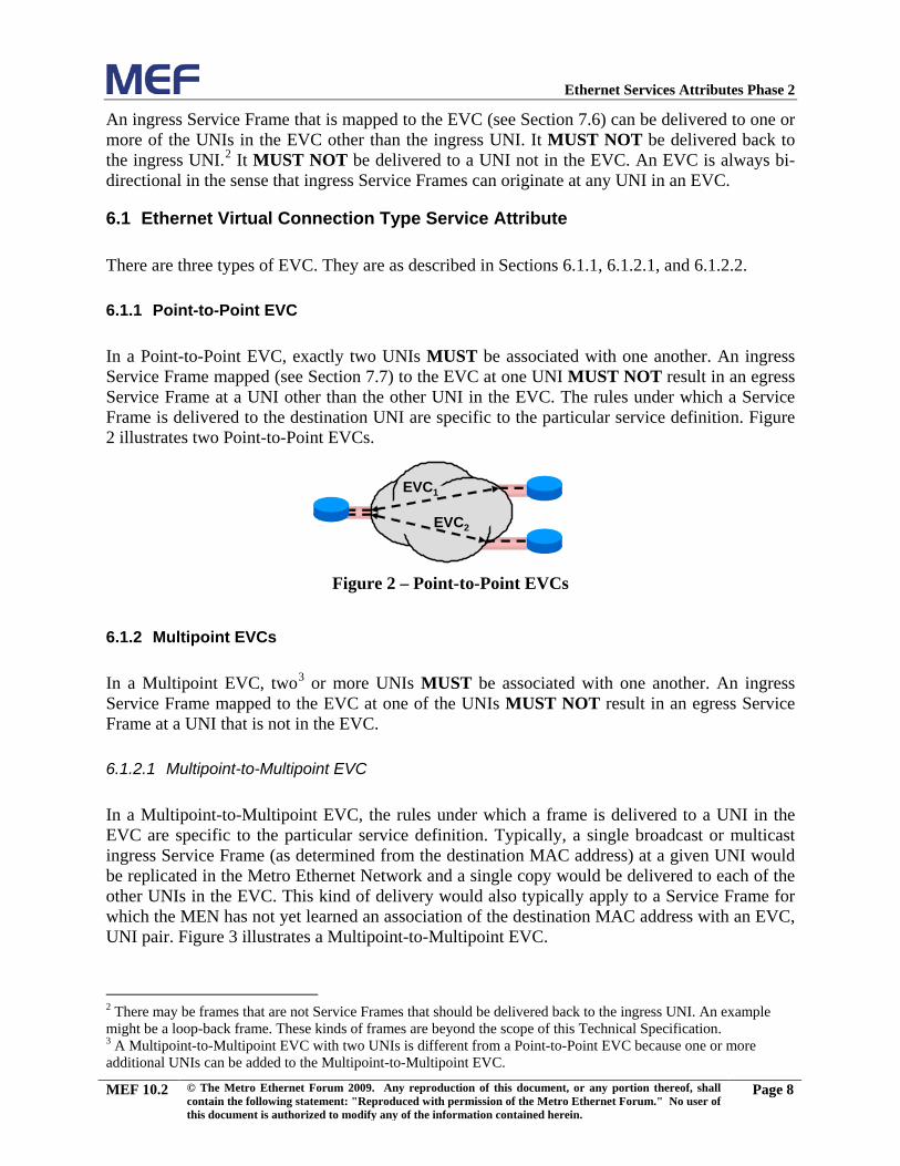
In a Point-to-Point EVC, exactly two UNIs MUST be associated with one another. An ingress Service Frame mapped (see Section 7.7) to the EVC at one UNI MUST NOT result in an egress Service Frame at a UNI other than the other UNI in the EVC. The rules under which a Service Frame is delivered to the destination UNI are specific to the particular service definition. Figure 2 illustrates two Point-to-Point EVCs.
EVC1
EVC2
Figure 2 – Point-to-Point EVCs
6.1.2 Multipoint EVCs
In a Multipoint EVC, two3 or more UNIs MUST be associated with one another. An ingress Service Frame mapped to the EVC at one of the UNIs MUST NOT result in an egress Service Frame at a UNI that is not in the EVC.
6.1.2.1 Multipoint-to-Multipoint EVC
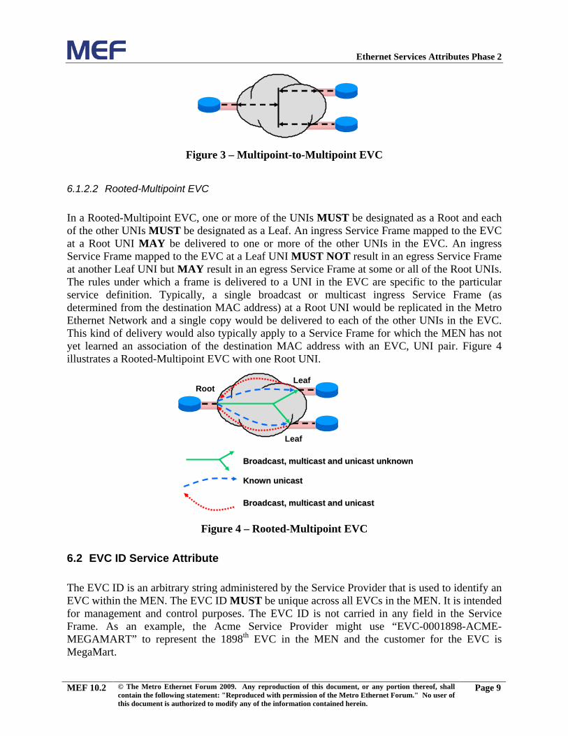
In a Multipoint-to-Multipoint EVC, the rules under which a frame is delivered to a UNI in the EVC are specific to the particular service definition. Typically, a single broadcast or multicast ingress Service Frame (as determined from the destination MAC address) at a given UNI would be replicated in the Metro Ethernet Network and a single copy would be delivered to each of the other UNIs in the EVC. This kind of delivery would also typically apply to a Service Frame for which the MEN has not yet learned an association of the destination MAC address with an EVC, UNI pair. Figure 3 illustrates a Multipoint-to-Multipoint EVC.
2 There may be frames that are not Service Frames that should be delivered back to the ingress UNI. An example might be a loop-back frame. These kinds of frames are beyond the scope of this Technical Specification. 3 A Multipoint-to-Multipoint EVC with two UNIs is different from a Point-to-Point EVC because one or more additional UNIs can be added to the Multipoint-to-Multipoint EVC.
Ethernet Services Attributes Phase 2
MEF 10.2 © The Metro Ethernet Forum 2009. Any reproduction of this document, or any portion thereof, shall contain the following statement: "Reproduced with permission of the Metro Ethernet Forum." No user of this document is authorized to modify any of the information contained herein.
Page 9
Figure 3 – Multipoint-to-Multipoint EVC
6.1.2.2 Rooted-Multipoint EVC
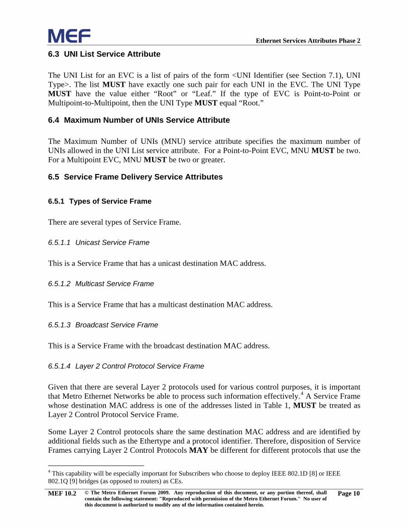
In a Rooted-Multipoint EVC, one or more of the UNIs MUST be designated as a Root and each of the other UNIs MUST be designated as a Leaf. An ingress Service Frame mapped to the EVC at a Root UNI MAY be delivered to one or more of the other UNIs in the EVC. An ingress Service Frame mapped to the EVC at a Leaf UNI MUST NOT result in an egress Service Frame at another Leaf UNI but MAY result in an egress Service Frame at some or all of the Root UNIs. The rules under which a frame is delivered to a UNI in the EVC are specific to the particular service definition. Typically, a single broadcast or multicast ingress Service Frame (as determined from the destination MAC address) at a Root UNI would be replicated in the Metro Ethernet Network and a single copy would be delivered to each of the other UNIs in the EVC. This kind of delivery would also typically apply to a Service Frame for which the MEN has not yet learned an association of the destination MAC address with an EVC, UNI pair. Figure 4 illustrates a Rooted-Multipoint EVC with one Root UNI.
RootLeaf
Leaf
Broadcast, multicast and Broadcast, multicast and unicastunicast unknownunknown
Known Known unicastunicast
Broadcast, multicast and Broadcast, multicast and unicastunicast
Figure 4 – Rooted-Multipoint EVC
6.2 EVC ID Service Attribute
The EVC ID is an arbitrary string administered by the Service Provider that is used to identify an EVC within the MEN. The EVC ID MUST be unique across all EVCs in the MEN. It is intended for management and control purposes. The EVC ID is not carried in any field in the Service Frame. As an example, the Acme Service Provider might use “EVC-0001898-ACME-MEGAMART” to represent the 1898th EVC in the MEN and the customer for the EVC is MegaMart.
Ethernet Services Attributes Phase 2
MEF 10.2 © The Metro Ethernet Forum 2009. Any reproduction of this document, or any portion thereof, shall contain the following statement: "Reproduced with permission of the Metro Ethernet Forum." No user of this document is authorized to modify any of the information contained herein.
Page 10
6.3 UNI List Service Attribute
The UNI List for an EVC is a list of pairs of the form <UNI Identifier (see Section 7.1), UNI Type>. The list MUST have exactly one such pair for each UNI in the EVC. The UNI Type MUST have the value either “Root” or “Leaf.” If the type of EVC is Point-to-Point or Multipoint-to-Multipoint, then the UNI Type MUST equal “Root.”
6.4 Maximum Number of UNIs Service Attribute
The Maximum Number of UNIs (MNU) service attribute specifies the maximum number of UNIs allowed in the UNI List service attribute. For a Point-to-Point EVC, MNU MUST be two. For a Multipoint EVC, MNU MUST be two or greater.
6.5 Service Frame Delivery Service Attributes
6.5.1 Types of Service Frame
There are several types of Service Frame.
6.5.1.1 Unicast Service Frame
This is a Service Frame that has a unicast destination MAC address.
6.5.1.2 Multicast Service Frame
This is a Service Frame that has a multicast destination MAC address.
6.5.1.3 Broadcast Service Frame
This is a Service Frame with the broadcast destination MAC address.
6.5.1.4 Layer 2 Control Protocol Service Frame
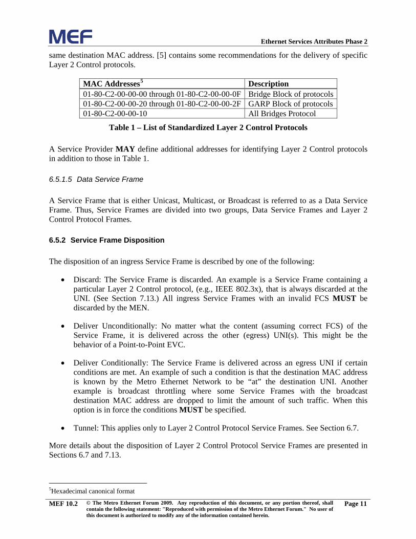
Given that there are several Layer 2 protocols used for various control purposes, it is important that Metro Ethernet Networks be able to process such information effectively.4 A Service Frame whose destination MAC address is one of the addresses listed in Table 1, MUST be treated as Layer 2 Control Protocol Service Frame.
Some Layer 2 Control protocols share the same destination MAC address and are identified by additional fields such as the Ethertype and a protocol identifier. Therefore, disposition of Service Frames carrying Layer 2 Control Protocols MAY be different for different protocols that use the
4 This capability will be especially important for Subscribers who choose to deploy IEEE 802.1D [8] or IEEE 802.1Q [9] bridges (as opposed to routers) as CEs.
Ethernet Services Attributes Phase 2
MEF 10.2 © The Metro Ethernet Forum 2009. Any reproduction of this document, or any portion thereof, shall contain the following statement: "Reproduced with permission of the Metro Ethernet Forum." No user of this document is authorized to modify any of the information contained herein.
Page 11
same destination MAC address. [5] contains some recommendations for the delivery of specific Layer 2 Control protocols.
MAC Addresses5 Description 01-80-C2-00-00-00 through 01-80-C2-00-00-0F Bridge Block of protocols 01-80-C2-00-00-20 through 01-80-C2-00-00-2F GARP Block of protocols 01-80-C2-00-00-10 All Bridges Protocol
Table 1 – List of Standardized Layer 2 Control Protocols
A Service Provider MAY define additional addresses for identifying Layer 2 Control protocols in addition to those in Table 1.
6.5.1.5 Data Service Frame
A Service Frame that is either Unicast, Multicast, or Broadcast is referred to as a Data Service Frame. Thus, Service Frames are divided into two groups, Data Service Frames and Layer 2 Control Protocol Frames.
6.5.2 Service Frame Disposition
The disposition of an ingress Service Frame is described by one of the following:
• Discard: The Service Frame is discarded. An example is a Service Frame containing a particular Layer 2 Control protocol, (e.g., IEEE 802.3x), that is always discarded at the UNI. (See Section 7.13.) All ingress Service Frames with an invalid FCS MUST be discarded by the MEN.
• Deliver Unconditionally: No matter what the content (assuming correct FCS) of the Service Frame, it is delivered across the other (egress) UNI(s). This might be the behavior of a Point-to-Point EVC.
• Deliver Conditionally: The Service Frame is delivered across an egress UNI if certain conditions are met. An example of such a condition is that the destination MAC address is known by the Metro Ethernet Network to be “at” the destination UNI. Another example is broadcast throttling where some Service Frames with the broadcast destination MAC address are dropped to limit the amount of such traffic. When this option is in force the conditions MUST be specified.
• Tunnel: This applies only to Layer 2 Control Protocol Service Frames. See Section 6.7.
More details about the disposition of Layer 2 Control Protocol Service Frames are presented in Sections 6.7 and 7.13.
5Hexadecimal canonical format
Ethernet Services Attributes Phase 2
MEF 10.2 © The Metro Ethernet Forum 2009. Any reproduction of this document, or any portion thereof, shall contain the following statement: "Reproduced with permission of the Metro Ethernet Forum." No user of this document is authorized to modify any of the information contained herein.
Page 12
Note that this is a description of the ideal service. Service Frames that should be delivered might be discarded due to network failure or congestion conditions. See the EVC Related Performance Service Attributes in Section 6.8.
6.5.3 Service Frame Transparency
All fields of each egress Service Frame MUST be identical to the same fields of the corresponding ingress Service Frame except as follows:
• The egress Service Frame MAY have an IEEE 802.1Q Customer VLAN Tag [10] while the corresponding ingress Service Frame does not. In this case the egress Service Frame MUST have a recalculated FCS.
• The egress Service Frame MAY not have an IEEE 802.1Q Customer VLAN Tag [10] while the corresponding ingress Service Frame does have a Tag. In this case the egress Service Frame MUST have a recalculated FCS.
• If both the egress Service frame and corresponding ingress Service Frame have an IEEE 802.1Q Customer VLAN Tag [10], the contents of the Tag in the egress Service Frame MAY be different from the contents of the Tag in the corresponding ingress Service Frame. If the contents of the ingress and egress tags are different, the egress Service Frame MUST have a recalculated FCS.
However, specific attributes of an EVC MAY enforce the condition that additional fields must be identical at ingress and egress. See Section 6.6.
6.6 CE-VLAN Tag Preservation Service Attributes
Service Frames at the UNI may contain an IEEE 802.1Q Customer VLAN Tag [10]. Such a Tag is referred to as a Customer Edge VLAN Tag (CE-VLAN Tag). The portion of the CE-VLAN Tag that identifies a VLAN indicates the Customer Edge VLAN ID (CE-VLAN ID). (See Section 7.6.) The portion of the CE-VLAN Tag that contains the Priority Code Point bits is called the Customer Edge VLAN CoS (CE-VLAN CoS). An EVC MAY have two attributes related to CE-VLAN Tag Preservation as described in the following two subsections.
6.6.1 CE-VLAN ID Preservation Service Attribute
A Service Frame is defined to have its CE-VLAN ID Preserved when the relationship between the ingress Service Frame and its corresponding egress Service Frame(s) is as described in Table 2.
Ethernet Services Attributes Phase 2
MEF 10.2 © The Metro Ethernet Forum 2009. Any reproduction of this document, or any portion thereof, shall contain the following statement: "Reproduced with permission of the Metro Ethernet Forum." No user of this document is authorized to modify any of the information contained herein.
Page 13
Ingress Service Frame Egress Service Frame(s)6 No IEEE 802.1Q Customer VLAN Tag [10]
No IEEE 802.1Q Customer VLAN Tag [10]
Contains IEEE 802.1Q Customer VLAN Tag [10]
Contains IEEE 802.1Q Customer VLAN Tag [10] with VLAN ID equal to the VLAN ID of the Tag on the ingress Service Frame
Table 2 – CE-VLAN ID Preservation for a Service Frame
An EVC with the CE-VLAN ID Preservation Service Attribute MUST preserve the CE-VLAN ID for Service Frames as described in Table 3. CE-VLAN ID/EVC Map Characteristic
Service Frames with CE-VLAN ID Preserved
All to One Bundling at all UNIs All Data Service Frames All other cases All tagged Data Service Frames with VLAN ID in the
range 1 – 4094
Table 3 – CE-VLAN ID Preservation Service Attribute for an EVC
When an EVC includes a UNI at which more than one CE-VLAN ID is mapped to the EVC by the CE-VLAN ID/EVC Map (see Sections 7.9 and 7.10), the EVC MUST have the CE-VLAN ID Preservation Service Attribute.
Note that when the CE-VLAN ID configured for untagged and priority tagged Service Frames (see Section 7.6.1) is mapped to an EVC with the CE-VLAN ID Preservation Service Attribute, ingress untagged and priority tagged Service Frames at this UNI are not mandated to have their CE-VLAN ID preserved except in the case of All to One Bundling.
An obvious benefit of the CE-VLAN ID Preservation feature is enhanced operational simplicity. For example, for a Subscriber connecting multiple campuses using IEEE 802.1Q bridges, the feature obviates the task of renumbering VLANs in different corporate campuses.
6.6.2 CE-VLAN CoS Preservation Service Attribute
In an EVC with CE-VLAN CoS Preservation, an egress Service Frame resulting from an ingress Service Frame that contains a CE-VLAN CoS MUST have the identical CE-VLAN CoS.
6.7 EVC Layer 2 Control Protocol Processing Service Attribute
In some cases, it is desirable to carry Layer 2 Control Protocols across the Service Provider network. This is called Layer 2 Control Protocol tunneling because the frame MUST be passed through the Service Provider network without being processed7 and delivered to the proper UNI
6 Note that in the case of a Multipoint EVC, a single ingress Service Frame can result in more than one egress Service Frame. 7 For example, the Subscriber’s Ethernet information can be encapsulated in another frame separate from the control protocol frame.
Ethernet Services Attributes Phase 2
MEF 10.2 © The Metro Ethernet Forum 2009. Any reproduction of this document, or any portion thereof, shall contain the following statement: "Reproduced with permission of the Metro Ethernet Forum." No user of this document is authorized to modify any of the information contained herein.
Page 14
or UNIs. The tunneling capability can be extremely useful, for example, when the Subscriber chooses to attach bridges to all UNIs and thus BPDUs need to be carried across the Network. When a Layer 2 Control Protocol is tunneled, the Service Frame at each egress UNI MUST be identical to the corresponding ingress Service Frame.
For a given EVC at a given UNI, the Service Provider defines which Layer 2 Control Protocols will be tunneled via the EVC and which will be discarded. If a Service Frame carrying a Layer 2 Control Protocol is tunneled, it MUST be tunneled on the EVC that is identified by the CE-VLAN/EVC Map for the CE-VLAN ID indicated by the Service Frame carrying the Layer 2 Control Protocol.8 See Section 7.7.
Note that if a Layer 2 Control Protocol is to be tunneled, then all UNIs in the EVC MUST be configured to pass the Layer 2 Control Protocol to the EVC. See Section 7.13.3.
6.8 Class of Service Identifier Service Attribute
Service Frame delivery performance is specified for all Service Frames transported within an EVC with a particular Class of Service instance. The Class of Service instance for a given Service Frame is identified by a Class of Service Identifier that is indicated by content in one or more fields in the Service Frame. For example, suppose that three Classes of Service are offered called silver, gold, and platinum and, at a given UNI, there are three instances of silver service, two instances of gold service and one instance of platinum service. Then there would be six Class of Service Identifiers, one for each Class of Service instance.
A Service Frame delivery performance MAY be to discard the Service Frame. Thus a Class of Service Identifier may be specified for Service Frame discard.
Service Frames mapped to different EVCs MUST have different Class of Service Identifiers. There SHALL be three mutually exclusive ways to determine the Class of Service Identifier from the content of a given Service Frame as described in Sections 6.8.1, 6.8.2, and 6.8.3.
6.8.1 Class of Service Identifier Based on EVC
In this case, all ingress Data Service Frames mapped to the EVC SHALL have the same Class of Service Identifier.
As an example, consider EVC 1 and EVC 2 at a UNI. Data Service Frames on EVC 1 have a first Class of Service Identifier that indicates gold service. Data Service Frames on EVC 2 have a second Class of Service Identifier that indicates silver service. All tunneled Layer 2 Control Protocols on EVC 1 also have the first Class of Service Identifier thus indicating gold service. All tunneled Layer 2 Control Protocols on EVC 2 have a third Class of Service Identifier that indicates platinum service.
8 Tunneling of BPDUs when Service Multiplexing is in effect at a UNI can lead to undesirable behavior. For example, if bridges are attached to all UNIs, then tunneled BPDUs will not reach all of the bridges and the Spanning Tree Protocol will not operate properly.
Ethernet Services Attributes Phase 2
MEF 10.2 © The Metro Ethernet Forum 2009. Any reproduction of this document, or any portion thereof, shall contain the following statement: "Reproduced with permission of the Metro Ethernet Forum." No user of this document is authorized to modify any of the information contained herein.
Page 15
6.8.2 Class of Service Identifier Based on Priority Code Point Field
In this case, the Class of Service Identifier for an ingress Data Service Frame SHALL be determined by the EVC and non-overlapping sets of values of the CE-VLAN CoS. If the ingress Data Service Frame is untagged, it SHALL have the same Class of Service Identifier as an ingress Data Service Frame with Priority Code Point field = 0. The union of the sets of CE-VLAN CoS values MUST contain all of the possible CE-VLAN CoS values.
As an example, consider EVC 1 and EVC 2 at a UNI. Tagged and priority tagged Data Service Frames on EVC 1 with Priority Code Point values 4, 5, 6, and 7 have a first Class of Service Identifier that indicates gold service. Tagged and priority tagged Data Service Frames on EVC 1 with Priority Code Point values 0 and 3 have a second Class of Service Identifier that indicates silver service. Tagged and priority tagged Data Service Frames on EVC 1 with Priority Code Point values 1 and 2 have a third Class of Service Identifier that indicates Service Frame discard. Untagged Data Service Frames on EVC 1 also have the second Class of Service Identifier that indicates silver service. Tagged Data Service Frames on EVC 2 with Priority Code Point value 7 have a third Class of Service Identifier that indicates platinum service. All other Data Service Frames on EVC 2 have a fourth Class of Service Identifier that indicates gold service.
6.8.3 Class of Service Identifier Based on DSCP
In this case, the Class of Service Identifier for an ingress Data Service Frame containing an IP packet SHALL be determined by the EVC and non-overlapping sets of values of the DSCP.9 The union of the sets of DSCP values MUST contain all of the possible DSCP values. All ingress Data Service Frames not containing an IP packet and mapped to a given EVC SHALL have the same Class of Service Identifier with a value agreed upon by the Subscriber and the Service Provider.
6.8.4 Class of Service Identifier Based on Layer 2 Control Protocol
In each method for determining the Class of Service Identifier described in Sections 6.8.1, 6.8.2, and 6.8.3, in addition Layer 2 Control Protocols that are tunneled on the EVC MAY be divided up into subsets and each subset MAY have a Class of Service Identifier.10
6.9 EVC Related Performance Service Attributes
The EVC Related Performance Service Attributes specify the Service Frame delivery performance. Four performance attributes are considered in this specification. These are Frame Delay Performance, Inter-Frame Delay Variation Performance, Frame Loss Ratio Performance, and Availability Performance.
9 In IP version 4, the DSCP is contained in the TOS field. In IP version 6, the DSCP is contained in the Traffic Class Octet. 10 For example, Service Frames carrying a BPDU could be assigned one Class of Service Identifier while Service Frames carrying a GARP protocol message could be assigned a different Class of Service Identifier.

Ethernet Services Attributes Phase 2
MEF 10.2 © The Metro Ethernet Forum 2009. Any reproduction of this document, or any portion thereof, shall contain the following statement: "Reproduced with permission of the Metro Ethernet Forum." No user of this document is authorized to modify any of the information contained herein.
Page 16
Performance Attributes apply to “Qualified” Service Frames, which are frames that meet the following criteria for a given ordered pair of UNIs and a given Class of Service:
• Each Service Frame MUST be the first egress Service Frame at the same UNI j resulting from an ingress Service Frame at the other UNI i of the ordered pair. The Service Frame MAY be a Unicast (see Section 6.5.1.1), Multicast (see Section 6.5.1.2), Broadcast (see Section 6.5.1.3), or Layer 2 Control Protocol (see Section 6.5.1.4) Service Frame. Note that a single ingress Service Frame can result in multiple egress Service Frames, e.g., a Multicast Service Frame.
• The first bit of each Service Frame MUST arrive at the ingress UNI within the time interval T,
• Each Service Frame MUST have the Class of Service Identifier for the Class of Service instance in question, and
• Each ingress Service Frame MUST have an Ingress Bandwidth Profile compliance of Green.
Such Service Frames are elements of the set of Qualified Service Frames for an Ordered Pair of UNIs and a given Class of Service on an EVC.
Performance Attributes MUST NOT apply to Service Frames with the level of conformance determined to be Yellow or Red. Typically, the Frame Loss Ratio Performance will be degraded for Service Frames determined to be Yellow. Service Frames determined to be Red will be discarded. (See Section 7.11.2.5.)
For a given EVC and Class of Service instance, Performance Objectives MAY be specified over any given subset of the Ordered Pairs of UNIs (describing transmission direction) on the EVC. Once a subset of UNI pairs is defined, then all attributes in this section SHALL have performance objectives applying to that subset. Section 10.4 provides examples on how to structure these metrics to be UNI-oriented and EVC-oriented.
Values of the Service Frame delay, delay variation, and loss performance during periods of unavailable time MUST NOT be used to determine Service Frame delivery compliance. A process MUST be established to exclude all performance during unavailable periods from comparison with Service Frame performance objectives.
The assessment of all performance attributes SHOULD account for unexpected arrival phenomena, such as frame duplication, or frames arriving in a different order from that observed on ingress, and the presence of these phenomena alone do not necessarily exclude a Service Frame from the set of Qualified Service Frames.
6.9.1 Frame Delay Performance for a Point-to-Point EVC
NOTE – The contents of this section in [13] have been deleted, and the scope of Section 6.9.2 has been broadened to cover the Point-to-Point EVC case.
Ethernet Services Attributes Phase 2
MEF 10.2 © The Metro Ethernet Forum 2009. Any reproduction of this document, or any portion thereof, shall contain the following statement: "Reproduced with permission of the Metro Ethernet Forum." No user of this document is authorized to modify any of the information contained herein.
Page 17
6.9.2 One-way Frame Delay Performance for an EVC
This section defines three performance attributes: the One-way Frame Delay Performance corresponding to a percentile of the distribution, the One-way Mean Frame Delay, and the One-way Frame Delay Range.
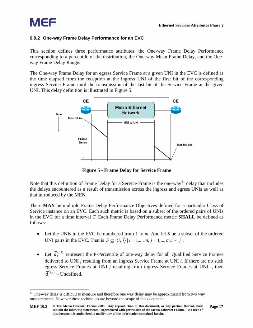
The One-way Frame Delay for an egress Service Frame at a given UNI in the EVC is defined as the time elapsed from the reception at the ingress UNI of the first bit of the corresponding ingress Service Frame until the transmission of the last bit of the Service Frame at the given UNI. This delay definition is illustrated in Figure 5.
Metro Ethernet Metro Ethernet NetworkNetwork
UNI to UNIUNI to UNIfirst bit infirst bit in
last bit outlast bit out
timetime
CECE CECE
FrameFrameDelayDelay
Figure 5 - Frame Delay for Service Frame
Note that this definition of Frame Delay for a Service Frame is the one-way11 delay that includes the delays encountered as a result of transmission across the ingress and egress UNIs as well as that introduced by the MEN.
There MAY be multiple Frame Delay Performance Objectives defined for a particular Class of Service instance on an EVC. Each such metric is based on a subset of the ordered pairs of UNIs in the EVC for a time interval T. Each Frame Delay Performance metric SHALL be defined as follows:
• Let the UNIs in the EVC be numbered from 1 to m. And let S be a subset of the ordered UNI pairs in the EVC. That is { }jimjmijiS ≠==⊆ ,,...,1,,...,1|, .
• Let jiTd , represent the P-Percentile of one-way delay for all Qualified Service Frames
delivered to UNI j resulting from an ingress Service Frame at UNI i. If there are no such egress Service Frames at UNI j resulting from ingress Service Frames at UNI i, then
=jiTd , Undefined.
11 One-way delay is difficult to measure and therefore one way delay may be approximated from two way measurements. However these techniques are beyond the scope of this document.

Ethernet Services Attributes Phase 2
MEF 10.2 © The Metro Ethernet Forum 2009. Any reproduction of this document, or any portion thereof, shall contain the following statement: "Reproduced with permission of the Metro Ethernet Forum." No user of this document is authorized to modify any of the information contained herein.
Page 18
• Then the One-way Frame Delay Performance metric SHALL be defined as the maximum value of all of the values ji
Td , for Sji ∈, , unless all jiTd , are Undefined in which case
the performance is Undefined.
• Let jiTx
jiTy
jiTyx ddd ,,, −= represent the difference between Percentiles Py and Px (where
Py > Px and i and j are the same pair in each term) of one-way delay for all Qualified Service Frames delivered to UNI j resulting from an ingress Service Frame at UNI i. If there are no such egress Service Frames at UNI j resulting from ingress Service Frames at UNI i, then =ji
Txyd , Undefined.
• Then the One-way Frame Delay Range Performance metric SHALL be defined as the maximum value of all of the values of the difference ji
Txji
Tyji
Tyx ddd ,,, −= for Sji ∈, ,
unless all jiTxyd , are Undefined in which case the performance is Undefined.
• Let jiT
,µ represent the arithmetic mean of one-way delay for all Qualified Service Frames delivered to UNI j resulting from an ingress Service Frame at UNI i. If there are no such egress Service Frames at UNI j resulting from ingress Service Frames at UNI i, then =ji
T,µ Undefined.
• Then the One-way Mean Frame Delay Performance metric SHALL be defined as the maximum value of all of the values ji
T,µ for Sji ∈, , unless all ji
T,µ are Undefined in
which case the performance is Undefined.
To restate the Frame Delay definition mathematically, let the UNIs in the EVC be numbered from 1 to m and let ji
TD , be the set of one-way Frame Delay values for all Qualified Service
Frames at UNI j resulting from an ingress Service Frame at UNI i. jiTD , can be expressed as
{ }jiN
jijijiT ji
dddD ,,2
,1
,,
,...,,= , where jikd , is the one-way Frame Delay of the kth Service Frame.
Define jiTd , for P > 0 as
( )
≥
≤= ∑=
otherwise
1 if ,100|min ,1
,
,
,
,
Undefined
NddIN
Pdd ji
N
k
jik
ji
jiT
ji
where,
( ) ≥
=otherwise 0
if 1, k
k
ddddI .

Ethernet Services Attributes Phase 2
MEF 10.2 © The Metro Ethernet Forum 2009. Any reproduction of this document, or any portion thereof, shall contain the following statement: "Reproduced with permission of the Metro Ethernet Forum." No user of this document is authorized to modify any of the information contained herein.
Page 19
jiTd , is the minimal delay during the time internal T that P percent of the frames do not exceed.
Note that when P>0, only values of d within jiTD , will satisfy P≤(100/N<i,k>)ΣI(d,dk).
Then a one-way Frame Delay Performance metric for an EVC can be expressed as
{ }
∈=>∈
=SjiNUndefined
NSjidd
ji
jiji
TST ,|0 all when
0 whereand ,|max
,
,,
, .
The One-way Frame Delay attribute permits specification of multiple values for P, (P0, P1, P2, …) and corresponding objectives ( jid ,
0ˆ , jid ,
1 , jid ,2
ˆ , …). Another parameter is the objective for the difference between the delay performance of two selected percentiles, Px and Py , expressed as
=>−
=0 if
0 if )(
,
,,,
,
ji
jiji
Txji
TyjiTyx NUndefined
Nddd
Then a one-way Frame Delay Range Performance metric for an EVC can be expressed as
{ }
,|0 all when 0 whereand ,|max
,
,,
∈=>∈
=SjiNUndefined
NSjidd
ji
jiji
TyxTyxS .
The minimum one-way delay is an element of jiTD , , where jid ,
min ≤ jikd , (for all
jiNk ,,...,2,1= ), and is a possible selection as one of the percentiles. The minimum delay represents the N<i,j>
-1th percentile and all lower values of P as 0→P .
Another One-way Frame Delay attribute is the arithmetic mean of jiTD , , which can be expressed
as
( )
=
>= ∑
=
0 if
0 if 1
,
,1
,
,,
,
ji
ji
N
k
jik
jiji
T
NUndefined
NdN
ji
µ
Then a One-way Mean Frame Delay Performance metric for an EVC can be expressed as
{ }
∈=>∈
=SjiNUndefined
NSji
ji
jiji
Tji
TTS ,|0 all when
0 where and ,|max
,
,,, µµ
µ .
The parameters of a One-way Frame Delay Performance metric are given in Table 4.

Ethernet Services Attributes Phase 2
MEF 10.2 © The Metro Ethernet Forum 2009. Any reproduction of this document, or any portion thereof, shall contain the following statement: "Reproduced with permission of the Metro Ethernet Forum." No user of this document is authorized to modify any of the information contained herein.
Page 20
Parameter Description T The time interval S Subset of the ordered UNI pairs of the EVC
xP A specific percentile of the Frame Delay Performance, 0>xP
yP Another specific percentile of the Frame Delay Performance, where xy PP >
xd One-way Frame Delay Performance Objective corresponding to xP
yd One-way Frame Delay Performance Objective corresponding to yP
yxd One-way Frame Delay Range Objective corresponding to the Frame Delay Performance at Px and Py )( ,,, ji
Txji
Tyji
Tyx ddd −= where xy PP > µ One-way Mean Frame Delay Performance Objective
Table 4 – One-way Frame Delay Performance Parameters
Given T, S, xP , and a one-way Frame Delay Performance objective xd , expressed in time units, the one-way Frame Delay Performance SHALL be defined as met over the time interval T for the subset S if and only if xST dd ˆ
, ≤ . Further, given yP and a One-way Frame Delay Performance
objective yd , expressed in time units, the objective for one-way Frame Delay Range between xP and yP SHALL be defined as met over the time interval T for the subset S if and only if
yxTyxS dd ˆ≤ . Finally, given a One-way Mean Frame Delay Performance objective µ , expressed in time units, the Frame Delay Performance SHALL be defined as met over the time interval T if and only if µµ ˆ≤TS .
Recall that if any of the above Service Frame Performance attributes are Undefined for time interval T and ordered pair ji, , then the performance for that ordered pair SHALL be excluded from calculations on the performance of pairs in S. For a given set S, if the Service Performance is Undefined for all ordered pairs, then the performance for S SHALL be defined as compliant.
For a Point-to-Point EVC, S MAY include one or both of the ordered pairs of UNIs in the EVC.
For a Multipoint-to-Multipoint EVC, S MAY be any subset of the ordered pairs of UNIs in the EVC.
For a Rooted-Multipoint EVC, S MUST be such that all ordered pairs in S contain at least one UNI that is designated as a Root.
6.9.3 Inter-Frame Delay Variation Performance for a Point-to-Point EVC
NOTE – The contents of this section in [13] have been deleted, and the scope of Section 6.9.4 has been broadened to cover the Point-to-Point EVC case.

Ethernet Services Attributes Phase 2
MEF 10.2 © The Metro Ethernet Forum 2009. Any reproduction of this document, or any portion thereof, shall contain the following statement: "Reproduced with permission of the Metro Ethernet Forum." No user of this document is authorized to modify any of the information contained herein.
Page 21
6.9.4 Inter-Frame Delay Variation Performance for an EVC
Inter-Frame Delay Variation (IFDV) is the difference between the one-way delays of a pair of selected Service Frames. This definition is borrowed from RFC3393 [6] where IP packet delay variation is defined. For a particular Class of Service Identifier and an ordered pair of UNIs in the EVC, IFDV Performance is applicable to Qualified Service Frames.
NOTE – Earlier documents refer to Inter-Frame Delay Variation as “Frame Delay Variation”.
The Inter-Frame Delay Variation Performance SHALL be defined as the P-percentile of the absolute values of the difference between the Frame delays of all Qualified Service Frame pairs that satisfy the following conditions:
• The difference in the arrival times of the first bit of each Service Frame at the ingress UNI was exactly ∆t.
This definition is in agreement with the IP packet delay variation definition given in [6] where the delay variation is defined as the difference between the one-way delay of two packets selected according to some selection function and are within a given interval [T1, T2].
Inter-Frame Delay Variation Performance depends on the choice of the value for ∆t. Values for both ∆t and T typically should be chosen to achieve a reasonable level of statistical accuracy.
The choice of the value for ∆t can be related to the application timing information. As an example for voice applications where voice frames are generated at regular intervals, ∆t may be chosen to be few multiples of the inter-frame time.
Let ia be the time of the arrival of the first bit of the ith Service Frame at the ingress UNI, then the two frames i and j are selected according to the selection criterion:
{ }ijandtaa ij >∆=−
Let ir be the time frame i is successfully received (last bit of the frame) at the egress UNI, then the difference in the delays encountered by frame i and frame j is given by ji dd − . Define
( ) ( ) ( ) ( )ijijjjiijiij rraaararddd −−−=−−−=−=∆
With jd being the delay of the jth frame, a positive value for ji dd − implies that the two frames are closer together at the egress UNI while a negative value implies that the two frames are further apart at the egress UNI. If either or both frames are lost or not delivered due to, for example, FCS violation, then the value ijd∆ is not defined and does not contribute to the evaluation of the Inter-Frame Delay Variation.

Ethernet Services Attributes Phase 2
MEF 10.2 © The Metro Ethernet Forum 2009. Any reproduction of this document, or any portion thereof, shall contain the following statement: "Reproduced with permission of the Metro Ethernet Forum." No user of this document is authorized to modify any of the information contained herein.
Page 22
Figure 6 shows a depiction of the different times that are related to Inter-Frame Delay Variation Performance.
Ingress
Egress
i i+1 j+1j
ai aj
∆t
ri rj
Time
di dj Figure 6 – Inter-Frame Delay Variation Definition
For a particular Class of Service instance, Inter-Frame Delay Variation Performance metrics MAY be specified over any given subset of two or more UNIs on an EVC. Each such metric is based on a subset of the ordered pairs of UNIs in the EVC for a time interval T. Each Inter-Frame Delay Variation Performance metric SHALL be defined as follows:
• Let the UNIs in the EVC be numbered from 1 to m. And let S be a subset of the ordered UNI pairs in the EVC. That is { }jimjmijiS ≠==⊆ ,,...,1,,...,1|, .
• Let jiTd ,~
∆ be the P-percentile of the absolute value of the difference between the Frame Delays of all Qualified Service Frame pairs whose difference in the arrival times of the first bit of each Service Frame in the pair at UNI i was exactly t∆ .
• If there are no such pairs of Service Frames for UNI i and UNI j, then Undefinedd ji
T =∆ ,~ .
• Then the Inter-Frame Delay Variation Performance metric SHALL be the maximum of the values ji
Td ,~∆ for Sji ∈, , unless all ji
Td ,~∆ are Undefined in which case the
performance is Undefined.
To restate the definition mathematically, let the UNIs in the EVC be numbered from 1 to m. And let S be a subset of the ordered UNI pairs in the EVC. That is
{ }jimjmijiS ≠==⊆ ,,...,1,,...,1|, .
Let
},...,,{ ,,2
,1
,,
jiN
jijijiT ji
dddV ∆∆∆=

Ethernet Services Attributes Phase 2
MEF 10.2 © The Metro Ethernet Forum 2009. Any reproduction of this document, or any portion thereof, shall contain the following statement: "Reproduced with permission of the Metro Ethernet Forum." No user of this document is authorized to modify any of the information contained herein.
Page 23
be the set of all absolute value of delay variations for all eligible pairs of Qualified Service Frames from UNI i to UNI j where the difference in the arrival times of the first bit of each Service Frame at the ingress UNI was exactly ∆t. Define
≥
∆≤=∆ ∑=
otherwise
1 if ),(100|min~ ,1
,
,
,
,
Undefined
NddIN
Pdd ji
N
k
jik
ji
jiT
ji
where;
( )otherwise
if01
,dd
ddI∆≥
=∆ .
Then an Inter-Frame Delay Variation Performance metric for an EVC can be expressed as
{ }
∈=≥∈∆
=∆SjiNUndefined
NSjidd
ji
jiji
TST ,|0 all when
1 whereand ,|~max~
,
,,
, .
For the SLS, an Inter-Frame Delay Variation metric MUST specify a set of parameters and an objective. The parameters and objective for an Inter-Frame Delay Variation Performance metric are given in Table 5.
Parameter Description T The interval S Subset of the ordered UNI pairs of the EVC P Inter-Frame Delay Variation Performance percentile
∆t The separation between frame pairs for which Inter-Frame Delay Variation Performance is defined
d
Inter-Frame Delay Variation Performance Objective
Table 5 – Inter-Frame Delay Variation Parameters
Given T, S, P, ∆t, and d
, the Inter-Frame Delay Variation Performance SHALL be defined as met over the time interval T for the subset S if and only if dd ST
≤∆ ,
~ .
Recall that if the Inter-Frame Delay Variation is Undefined for time interval T and ordered pair ji, , then the performance for that ordered pair SHALL be excluded from calculations on the
performance of pairs in S. For a given set S, if the Service Performance is Undefined for all ordered pairs, then the performance for S SHALL be defined as compliant.
For a Point-to-Point EVC, S MAY be include one or both of the ordered pairs of UNIs in the EVC.

Ethernet Services Attributes Phase 2
MEF 10.2 © The Metro Ethernet Forum 2009. Any reproduction of this document, or any portion thereof, shall contain the following statement: "Reproduced with permission of the Metro Ethernet Forum." No user of this document is authorized to modify any of the information contained herein.
Page 24
For a Multipoint-to-Multipoint EVC, S MAY be any subset of the ordered pairs of UNIs in the EVC.
For a Rooted-Multipoint EVC, S MUST be such that all ordered pairs in S contain at least one UNI that is designated as a Root.
6.9.5 One-way Frame Loss Ratio Performance for a Point-to-Point EVC
NOTE – Section 6.9.7 refers to this section for the definition of the frame loss ratio ( )itflr ∆ of a Point-to-Point EVC. For the purposes of the Availability Performance, the Frame Loss Ratio Performance (defined in detail in Section 6.9.6) SHALL be defined as follows:
( ) { }
∈=
≥∈==∆
∆
∆∆∆ SjiI
ISjiFLRFLRtflr ji
t
jit
jit
Sti
i
ii
i ,|0 all when 01 whereand ,|max
,
,,
,
where the set of ordered pairs, S, contains both ordered pairs of UNIs in the Point-to-Point EVC.
NOTE – The contents of this section in [13] have been deleted, and the scope of Section 6.9.6 has been broadened to cover the Point-to-Point EVC case.
6.9.6 One-way Frame Loss Ratio Performance for an EVC
There MAY be multiple One-way Frame Loss Ratio Performance metrics defined for a particular Class of Service instance on an EVC. Each such metric is based on a subset of the ordered pairs of UNIs in the EVC for a time interval T. Each One-way Frame Loss Ratio Performance metric SHALL be defined as follows:
• Let the UNIs in the EVC be numbered from 1 to m. And let S be a subset of the ordered UNI pairs in the EVC. That is { }jimjmijiS ≠==⊆ ,,...,1,,...,1|, .
• Let jiTI , denote the number of ingress Service Frames at UNI i whose first bit arrived at
UNI i during the time interval T, whose Ingress Bandwidth Profile compliance was Green, and that should have been delivered to UNI j according to the Service Frame Delivery service attributes (see Sections 6.5.2, 6.7, and 7.13). Each Service Frame can be a Unicast (see Section 6.5.1.1), Multicast (see Section 6.5.1.2), Broadcast (see Section 6.5.1.3), or Layer 2 Control Protocol (see Section 6.5.1.4) Service Frame.
• Let jiTE , denote the number of such Service Frames delivered to UNI j.
• Define
≥×
−=
otherwise
1 if 100 ,,
,,
,
Undefined
II
EIFLR
jiTji
T
jiT
jiT
jiT .
Ethernet Services Attributes Phase 2
MEF 10.2 © The Metro Ethernet Forum 2009. Any reproduction of this document, or any portion thereof, shall contain the following statement: "Reproduced with permission of the Metro Ethernet Forum." No user of this document is authorized to modify any of the information contained herein.
Page 25
• Then the One-way Frame Loss Ratio Performance metric SHALL be defined as { }
∈=≥∈
=SjiIUndefined
ISjiFLRFLR ji
T
jiT
jiT
ST ,|0 all when 1 whereand ,|max
,
,,
, .
For the SLS, a One-way Frame Loss Ratio Performance metric entry MUST specify a set of parameters and an objective. The parameters and objective of a One-way Frame Loss Ratio Performance metric are given in Table 6.
Parameter Description T The time interval S Subset of the ordered UNI pairs L One-way Frame Loss Ratio Performance
objective
Table 6 – One-way Frame Loss Ratio Performance Parameters
Given T, S, and a One-way Frame Loss Ratio Performance objective, the One-way Frame Loss Performance SHALL be defined as met over the time interval T for the subset S if and only if
LFLR STˆ
, ≤ .
Recall that if the One-way Frame Loss Ratio Performance is Undefined for time interval T and ordered pair ji, , then the performance for that ordered pair SHALL be excluded from calculations on the performance of pairs in S. For a given set S, if the Service Performance is Undefined for all ordered pairs, then the performance for S SHALL be defined as compliant.
For a Point-to-Point EVC, S MAY include one or both of the ordered pairs of UNIs in the EVC.
For a Multipoint-to-Multipoint EVC, S MAY be any subset of the ordered pairs of UNIs in the EVC.
For a Rooted-Multipoint EVC, S MUST be such that all ordered pairs in S contain at least one UNI that is designated as a Root.
6.9.7 Availability Performance for a Point-to-Point EVC
Availability Performance is the percentage of time within a specified time interval during which the Frame Loss Ratio Performance (Section 6.9.5) is small. (The precise definition is presented in the following paragraphs.) As an example, a service provider can define the availability performance to be measured over a month and the value for the Availability Performance objective to be 99.9%. In a month with 30 days and no scheduled downtime this parameter will allow the service to be unavailable for approximately 43 minutes out of the whole month.
Informally, Availability Performance is based on Service Frame loss during a sequence of consecutive small time intervals. If the previous sequence was defined as available, and if the frame loss is high for each small time interval in the current sequence, then the current sequence

Ethernet Services Attributes Phase 2
MEF 10.2 © The Metro Ethernet Forum 2009. Any reproduction of this document, or any portion thereof, shall contain the following statement: "Reproduced with permission of the Metro Ethernet Forum." No user of this document is authorized to modify any of the information contained herein.
Page 26
is defined as unavailable. Otherwise the current sequence is defined as available. On the other hand, if the previous sequence was defined as unavailable, and if frame loss is low for each small time interval in the current sequence, then the current sequence is defined as available. Otherwise, the current sequence is defined as unavailable. The formal definition follows.
The Availability for a particular Class of Service instance on a Point-to-Point EVC for a time interval T is based on the following four parameters:
• t∆ , a time interval much smaller than T,
• uC , a loss ratio threshold which if equaled or exceeded suggests unavailability,
• aC , a loss ratio threshold which if not exceeded suggests availability with ua CC ≤ , and
• n , the number of consecutive small time intervals, t∆ , over which to assess availability.
Suppose the time interval [ ]10 ,ttT = and define ( )[ ] nitittitti ,...,2,1for ,,1 00 =∆+∆−+=∆ . Define sets of n consecutive small time intervals as ( ) ( ){ }knnknkk tttS ∆∆∆= +−+− ,...,, 2111 . Also define
( )itflr ∆ to be the Frame Loss Ratio defined in Section 6.9.5 with it∆ replacing T. Let
{ }TttT ii ⊂∆∆= |~ . Let K be the largest integer such that Kii StTt ∈∆∀∈∆ ,~ . In other words, KS is the last sequence of small time intervals completely contained in T.
Define the function ( )kDs to indicate if a sequence of small time intervals includes Scheduled Downtime:
( )
= otherwise 0
during Downtime Scheduledany is thereif 1 ks
SkD .
Scheduled Downtime is a time interval agreed upon by both the Subscriber and Service Provider during which a service may be disabled by the Service Provider.
Define the function ( )kDu to indicate if a sequence of small time intervals includes Unscheduled Downtime:
( )
= otherwise 0
during Downtime duledany Unsche is thereif 1 ku
SkD .
Unscheduled Downtime is a time interval not agreed upon by both the Subscriber and Service Provider during which the Service Provider determines that the service is not usable. The method by which the Service Provider determines that Unscheduled Downtime is occurring is beyond the scope of this document. When Unscheduled Downtime is occurring, the Service Provider may notify the Subscriber via the Ethernet Local Management Interface.[11]

Ethernet Services Attributes Phase 2
MEF 10.2 © The Metro Ethernet Forum 2009. Any reproduction of this document, or any portion thereof, shall contain the following statement: "Reproduced with permission of the Metro Ethernet Forum." No user of this document is authorized to modify any of the information contained herein.
Page 27
Let M be the number of sequences that contain Scheduled Downtime and no Unscheduled Downtime. These sequences are excluded when considering availability.
For notation simplicity define
( ) ( ) ∈∆∀≥∆
=otherwise 1
, if 0 kiui StCtflrkU and ( ) ( )
∈∆∀≤∆
=otherwise 0
, if 1 kiai StCtflrkA .
Finally define an indicator function ( )kSI as follows whose value is 1 if the service is available during kS and 0 otherwise:
( ) ( ) =
=otherwise 1
11 if 01
uDSI
( )
( )( )( ) ( )( )
( ) ( )( ) ( )( ) ( )( )( )
=====
=
=−
otherwise 1 and 0 and 0 if
1 and 0 if 11 if 0
1
kASIkDkDkU
kDkDkD
SIksu
su
u
k for Kk ,...,2= .
Note that any kS that has Unscheduled Downtime is defined as unavailable and thus Unscheduled Downtime overrides Scheduled Downtime during an interval kS .
Figure 7 illustrates four examples of calculating ( )kSI when there is no Scheduled Downtime and no Unscheduled Downtime. In this example, 4=n .
I(Sk-1) = 1 (available)
flr≥Cu flr≥Cu flr≥Cu flr≥Cu
Sk-1 Sk
I(Sk-1) = 1 (available) I(Sk) = 0 (unavailable)
flr≥Cu flr<Cu flr≥Cu flr≥Cu
I(Sk) = 1 (available)
flr≤Ca flr≤Ca flr≤Ca flr≤Ca
I(Sk-1) = 0 (unavailable) I(Sk) = 1 (available)
flr≤Ca flr>Ca flr≤Ca flr≤Ca
I(Sk) = 0 (unavailable)I(Sk-1) = 0 (unavailable)
t∆ t∆ t∆ t∆ t∆ t∆ t∆ t∆
t∆ t∆ t∆ t∆ t∆ t∆ t∆ t∆
t∆ t∆ t∆ t∆ t∆ t∆ t∆ t∆
t∆ t∆ t∆ t∆ t∆ t∆ t∆ t∆ Figure 7 – Examples of the Calculation of ( )kSI

Ethernet Services Attributes Phase 2
MEF 10.2 © The Metro Ethernet Forum 2009. Any reproduction of this document, or any portion thereof, shall contain the following statement: "Reproduced with permission of the Metro Ethernet Forum." No user of this document is authorized to modify any of the information contained herein.
Page 28
Then the Availability Performance metric SHALL be defined as
<
−
−= ∑
=
otherwise 100
if )(1001
KMMSIMKA
K
kk
T .
For the SLS, an Availability Performance metric MUST specify a set of parameters and an objective as shown in Table 7.
Parameter Description T The time interval t∆ A time interval much smaller than T uC Unavailability frame loss ratio threshold
aC Availability frame loss ratio threshold with ua CC ≤ n Number of consecutive small time intervals for assessing availability A Availability Performance objective
Table 7 – Availability Performance Parameters for a Point-to-Pointe EVC
Given T, t∆ , uC , aC , n, and an Availability Performance objective, A , the Availability
Performance SHALL be defined as met over the time interval T if and only if AATˆ≥ .
6.9.8 Availability Performance for a Multipoint EVC
There MAY be multiple Availability Performance metrics specified for a particular Class of Service instance on a Multipoint EVC. Each such metric is based on a subset of the pairs of UNIs in the Multipoint EVC and for a time interval T. Each Availability Performance metric SHALL be defined as follows: Let the UNIs in the EVC be numbered from 1 to m. And let S be a subset of the UNI pairs in the EVC. That is { }ijmjmijiS >==⊆ ,,...1,,...,1|, .
• Let t∆ be a time interval much smaller than T.
• Let uC be a loss ratio threshold which if equaled or exceeded suggests unavailability.
• Let aC be a loss ratio threshold which if not exceeded suggests availability with ua CC ≤ .
• Let n be the number of small time intervals, t∆ , over which to assess availability.
• Let jiTA , be denote the availability between UNI i and UNI j defined in Section 6.9.7 as
if there was a Point-to-Point EVC between UNI i and UNI j.

Ethernet Services Attributes Phase 2
MEF 10.2 © The Metro Ethernet Forum 2009. Any reproduction of this document, or any portion thereof, shall contain the following statement: "Reproduced with permission of the Metro Ethernet Forum." No user of this document is authorized to modify any of the information contained herein.
Page 29
• Then the Availability Performance metric SHALL be defined as { }SjiAA ji
TST ∈= ,|min ,, .
For the SLS, an Availability Performance metric MUST specify a set of parameters and an objective as shown in Table 8.
Parameter Description T The time interval S Subset of the UNI pairs t∆ A time interval much smaller than T uC Unavailability frame loss ratio threshold
aC Availability frame loss ratio threshold with ua CC ≤ n Number of consecutive small time intervals for assessing availability A Availability Performance objective
Table 8 – Availability Performance Parameters for a Multipoint EVC
Given T, S, t∆ , uC , aC , n, and an Availability Performance objective, A , the Availability
Performance SHALL be defined as met over the time interval T if and only if AA STˆ
, ≥ .
For a Multipoint-to-Multipoint EVC, S MAY be any subset of the pairs of UNIs in the EVC.
For a Rooted-Multipoint EVC, S MUST be such that all pairs in S contain at least one UNI that is designated as a Root.
6.10 EVC Maximum Transmission Unit Size Service Attribute
The EVC Maximum Transmission Unit Size service attribute specifies the maximum Service Frame size (in Bytes) allowed on the EVC. Every UNI in the EVC MUST be capable of supporting this Service Frame size.12 (See Section 7.4.) The MTU MUST be specified to have a value greater than or equal to 1522.
When an ingress Service Frame has length greater than the EVC Maximum Transmission Unit Size, the SLS, if any, for this frame SHALL not apply to its delivery performance and the result of a Bandwidth Profile that applies to this Service Frame is not defined.
7. UNI and EVC per UNI Service Attributes
This section describes attributes at each UNI. These attributes fall into two types:
• Attributes independent of the EVCs at the UNI and 12 The MTU Size for an EVC will be constrained by the MTU size of the network equipment used to carry the frame including the network equipment supporting each UNI. The method of calculating the MTU Size is beyond the scope of this specification.
Ethernet Services Attributes Phase 2
MEF 10.2 © The Metro Ethernet Forum 2009. Any reproduction of this document, or any portion thereof, shall contain the following statement: "Reproduced with permission of the Metro Ethernet Forum." No user of this document is authorized to modify any of the information contained herein.
Page 30
• Attributes associated with an EVC at the UNI.
When each attribute is described, its type is noted.
A UNI can have a number of characteristics that will be important to the way that the CE sees a service. One of the key aspects of a service description will be the allowable mix of UNIs with different characteristics in an EVC. For example, a specific (simple) service might require all UNIs to have the same speed at the physical layer. A more sophisticated service may allow a wide variety of speeds.
7.1 UNI Identifier Service Attribute
The UNI Identifier attribute is independent of the EVCs at the UNI. It is assigned to the UNI by the Service Provider. It MUST be a string and the string MAY have any value. The UNI Identifier MUST be unique among all UNIs for the MEN. As an example, the Service Provider might use “SCPOP1-Node3-Slot2-Port1" as a UNI Identifier and this could signify Port 1 in Slot 2 of Node 3 in Santa Clara POP1.
7.2 Physical Layer Service Attribute
For a UNI, the Speed (in bits per second), Mode, and Physical Medium MUST be one of the combinations shown in Table 9. Typically there are no constraints in mixing UNIs with different physical media in the same EVC.13 Constraints on the mix of speeds and modes MAY be imposed for some services.
Speed Mode Physical Medium 10 Mbps Full duplex
All Ethernet physical media compatible with Speed and Mode specified in [2] or [3].
100 Mbps Full duplex 10/100 Mbps Auto-Negotiation
Full duplex
1 Gbps Full duplex 10 Gbps Full duplex
Table 9 – Possible Physical Layer Characteristics
This attribute is independent of the EVCs at the UNI.
7.3 MAC Layer Service Attribute
The protocols running at the UNI MUST support the IEEE 802.3 – 2005 [2] frame formats with the possible exception that the information field MAY be larger than 1500 bytes. (See Sections 6.10 and 7.4.) This attribute is independent of the EVCs at the UNI.
13 An exception might be wireless when the service requires stringent requirements on packet loss.
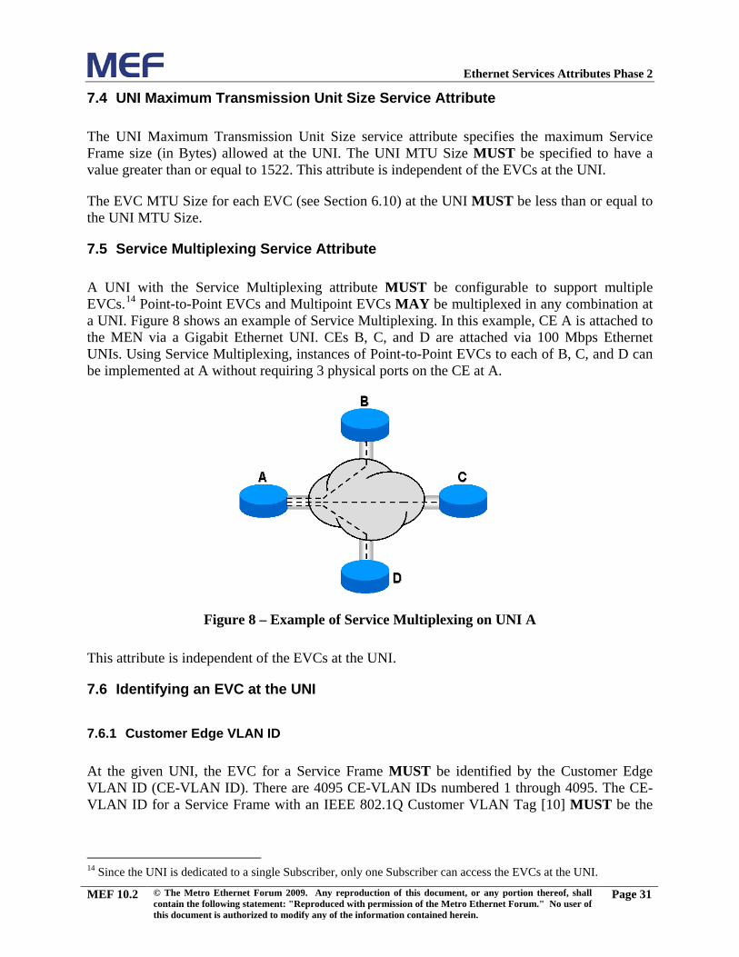
Ethernet Services Attributes Phase 2
MEF 10.2 © The Metro Ethernet Forum 2009. Any reproduction of this document, or any portion thereof, shall contain the following statement: "Reproduced with permission of the Metro Ethernet Forum." No user of this document is authorized to modify any of the information contained herein.
Page 31
7.4 UNI Maximum Transmission Unit Size Service Attribute
The UNI Maximum Transmission Unit Size service attribute specifies the maximum Service Frame size (in Bytes) allowed at the UNI. The UNI MTU Size MUST be specified to have a value greater than or equal to 1522. This attribute is independent of the EVCs at the UNI.
The EVC MTU Size for each EVC (see Section 6.10) at the UNI MUST be less than or equal to the UNI MTU Size.
7.5 Service Multiplexing Service Attribute
A UNI with the Service Multiplexing attribute MUST be configurable to support multiple EVCs.14 Point-to-Point EVCs and Multipoint EVCs MAY be multiplexed in any combination at a UNI. Figure 8 shows an example of Service Multiplexing. In this example, CE A is attached to the MEN via a Gigabit Ethernet UNI. CEs B, C, and D are attached via 100 Mbps Ethernet UNIs. Using Service Multiplexing, instances of Point-to-Point EVCs to each of B, C, and D can be implemented at A without requiring 3 physical ports on the CE at A.
Figure 8 – Example of Service Multiplexing on UNI A
This attribute is independent of the EVCs at the UNI.
7.6 Identifying an EVC at the UNI
7.6.1 Customer Edge VLAN ID
At the given UNI, the EVC for a Service Frame MUST be identified by the Customer Edge VLAN ID (CE-VLAN ID). There are 4095 CE-VLAN IDs numbered 1 through 4095. The CE-VLAN ID for a Service Frame with an IEEE 802.1Q Customer VLAN Tag [10] MUST be the
14 Since the UNI is dedicated to a single Subscriber, only one Subscriber can access the EVCs at the UNI.
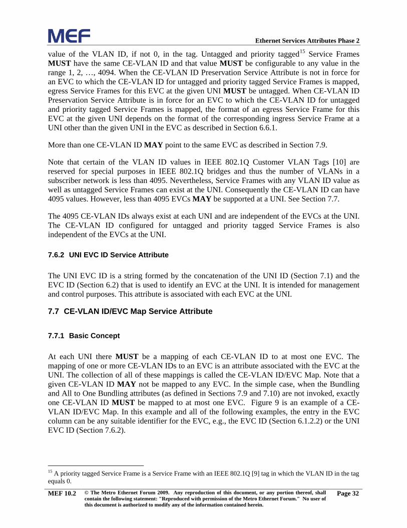
Ethernet Services Attributes Phase 2
MEF 10.2 © The Metro Ethernet Forum 2009. Any reproduction of this document, or any portion thereof, shall contain the following statement: "Reproduced with permission of the Metro Ethernet Forum." No user of this document is authorized to modify any of the information contained herein.
Page 32
value of the VLAN ID, if not 0, in the tag. Untagged and priority tagged15 Service Frames MUST have the same CE-VLAN ID and that value MUST be configurable to any value in the range 1, 2, …, 4094. When the CE-VLAN ID Preservation Service Attribute is not in force for an EVC to which the CE-VLAN ID for untagged and priority tagged Service Frames is mapped, egress Service Frames for this EVC at the given UNI MUST be untagged. When CE-VLAN ID Preservation Service Attribute is in force for an EVC to which the CE-VLAN ID for untagged and priority tagged Service Frames is mapped, the format of an egress Service Frame for this EVC at the given UNI depends on the format of the corresponding ingress Service Frame at a UNI other than the given UNI in the EVC as described in Section 6.6.1.
More than one CE-VLAN ID MAY point to the same EVC as described in Section 7.9.
Note that certain of the VLAN ID values in IEEE 802.1Q Customer VLAN Tags [10] are reserved for special purposes in IEEE 802.1Q bridges and thus the number of VLANs in a subscriber network is less than 4095. Nevertheless, Service Frames with any VLAN ID value as well as untagged Service Frames can exist at the UNI. Consequently the CE-VLAN ID can have 4095 values. However, less than 4095 EVCs MAY be supported at a UNI. See Section 7.7.
The 4095 CE-VLAN IDs always exist at each UNI and are independent of the EVCs at the UNI. The CE-VLAN ID configured for untagged and priority tagged Service Frames is also independent of the EVCs at the UNI.
7.6.2 UNI EVC ID Service Attribute
The UNI EVC ID is a string formed by the concatenation of the UNI ID (Section 7.1) and the EVC ID (Section 6.2) that is used to identify an EVC at the UNI. It is intended for management and control purposes. This attribute is associated with each EVC at the UNI.
7.7 CE-VLAN ID/EVC Map Service Attribute
7.7.1 Basic Concept
At each UNI there MUST be a mapping of each CE-VLAN ID to at most one EVC. The mapping of one or more CE-VLAN IDs to an EVC is an attribute associated with the EVC at the UNI. The collection of all of these mappings is called the CE-VLAN ID/EVC Map. Note that a given CE-VLAN ID MAY not be mapped to any EVC. In the simple case, when the Bundling and All to One Bundling attributes (as defined in Sections 7.9 and 7.10) are not invoked, exactly one CE-VLAN ID MUST be mapped to at most one EVC. Figure 9 is an example of a CE-VLAN ID/EVC Map. In this example and all of the following examples, the entry in the EVC column can be any suitable identifier for the EVC, e.g., the EVC ID (Section 6.1.2.2) or the UNI EVC ID (Section 7.6.2).
15 A priority tagged Service Frame is a Service Frame with an IEEE 802.1Q [9] tag in which the VLAN ID in the tag equals 0.

Ethernet Services Attributes Phase 2
MEF 10.2 © The Metro Ethernet Forum 2009. Any reproduction of this document, or any portion thereof, shall contain the following statement: "Reproduced with permission of the Metro Ethernet Forum." No user of this document is authorized to modify any of the information contained herein.
Page 33
CE-VLAN ID EVC 47 EVC1 1343 EVC2 1716 EVC3
EVC1 EVC2
EVC3
471343
untagged andpriority tagged, 17 UNI
Figure 9 – Example of a CE-VLAN ID/EVC Map
In this example, an ingress Service Frame with CE-VLAN ID 47 is transported according to the properties and attributes of EVC1. An untagged or priority tagged ingress Service Frame is transported according to the properties and attributes of EVC3. An egress frame coming from EVC2 is given CE-VLAN ID 1343.
When an instance of the CE-VLAN ID/EVC Map does not contain an entry for a given CE-VLAN ID, any ingress Service Frame at the UNI with this CE-VLAN ID MUST be discarded by the MEN. Also, an egress Service Frame MUST NOT have a CE-VLAN ID with this value at the UNI while using this instance of the CE-VLAN ID/EVC Map.
In some scenarios, it may be necessary for the Subscriber and the Service Provider to agree upon the CE-VLAN ID/EVC Map at the UNI. One way to implement this is to have the Service Provider dictate the mapping. This is what is frequently done with the mapping between DLCIs and permanent virtual connections for Frame Relay. Also note that for a given UNI, the CE-VLAN ID/EVC Map may be constrained by the range of CE-VLAN ID values that can be supported by the CE and the range of CE-VLAN ID values that can be supported by the Service Provider.17
7.7.2 CE-VLAN ID Significance
CE-VLAN ID values MAY only be significant at a given UNI. Restated, the CE-VLAN ID/EVC mapping for a given EVC at a UNI MAY be different from the mapping at another UNI in the EVC. Figure 10 shows valid CE-VLAN ID/EVC Maps for three EVCs between two UNIs. Note that when the CE-VLAN ID Preservation attribute (Section 6.6.1) applies to an EVC, the
16 In this example, the CE-VLAN ID for untagged and priority tagged Service Frames is configured to 17. 17 In a future Technical Specification, dynamic EVC setup via a signaling protocol across the UNI may be specified. In that case, it may be desirable to specify the range of CE-VLAN ID values supported by the Service Provider as a UNI attribute. In this phase of this Technical Specification, resolving the CE-VLAN ID/EVC Map is assumed to be done administratively and thus this specifying of a CE-VLAN ID range is not needed.
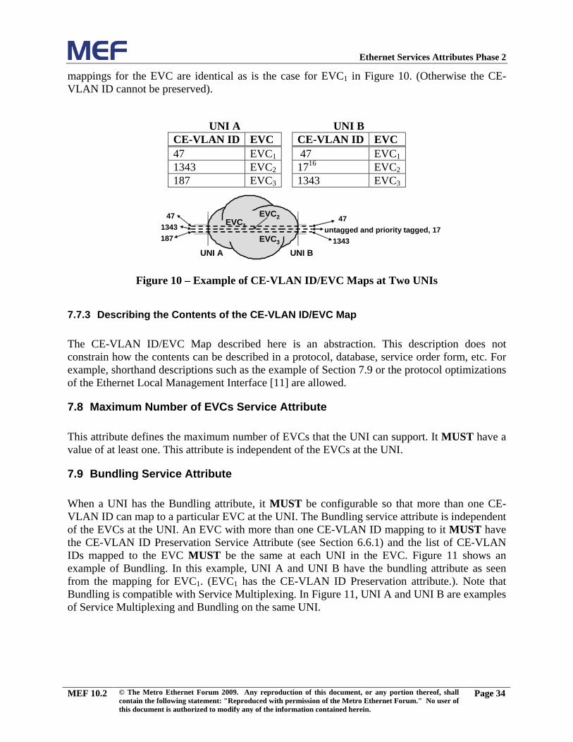
Ethernet Services Attributes Phase 2
MEF 10.2 © The Metro Ethernet Forum 2009. Any reproduction of this document, or any portion thereof, shall contain the following statement: "Reproduced with permission of the Metro Ethernet Forum." No user of this document is authorized to modify any of the information contained herein.
Page 34
mappings for the EVC are identical as is the case for EVC1 in Figure 10. (Otherwise the CE-VLAN ID cannot be preserved).
UNI A UNI B
CE-VLAN ID EVC CE-VLAN ID EVC 47 EVC1 47 EVC1 1343 EVC2 1716 EVC2 187 EVC3 1343 EVC3
EVC1
EVC2
EVC3
471343187
UNI A UNI B
47
1343untagged and priority tagged, 17
Figure 10 – Example of CE-VLAN ID/EVC Maps at Two UNIs
7.7.3 Describing the Contents of the CE-VLAN ID/EVC Map
The CE-VLAN ID/EVC Map described here is an abstraction. This description does not constrain how the contents can be described in a protocol, database, service order form, etc. For example, shorthand descriptions such as the example of Section 7.9 or the protocol optimizations of the Ethernet Local Management Interface [11] are allowed.
7.8 Maximum Number of EVCs Service Attribute
This attribute defines the maximum number of EVCs that the UNI can support. It MUST have a value of at least one. This attribute is independent of the EVCs at the UNI.
7.9 Bundling Service Attribute
When a UNI has the Bundling attribute, it MUST be configurable so that more than one CE-VLAN ID can map to a particular EVC at the UNI. The Bundling service attribute is independent of the EVCs at the UNI. An EVC with more than one CE-VLAN ID mapping to it MUST have the CE-VLAN ID Preservation Service Attribute (see Section 6.6.1) and the list of CE-VLAN IDs mapped to the EVC MUST be the same at each UNI in the EVC. Figure 11 shows an example of Bundling. In this example, UNI A and UNI B have the bundling attribute as seen from the mapping for EVC1. (EVC1 has the CE-VLAN ID Preservation attribute.). Note that Bundling is compatible with Service Multiplexing. In Figure 11, UNI A and UNI B are examples of Service Multiplexing and Bundling on the same UNI.
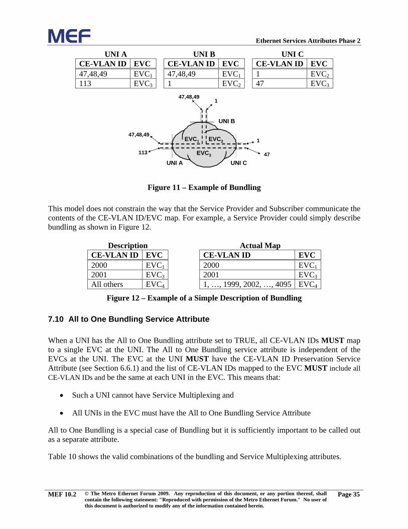
Ethernet Services Attributes Phase 2
MEF 10.2 © The Metro Ethernet Forum 2009. Any reproduction of this document, or any portion thereof, shall contain the following statement: "Reproduced with permission of the Metro Ethernet Forum." No user of this document is authorized to modify any of the information contained herein.
Page 35
UNI A UNI B UNI C CE-VLAN ID EVC CE-VLAN ID EVC CE-VLAN ID EVC 47,48,49 EVC1 47,48,49 EVC1 1 EVC2 113 EVC3 1 EVC2 47 EVC3
EVC1 EVC2
EVC3
47,48,49
113
UNI A UNI C47
UNI B
47,48,49
1
1
Figure 11 – Example of Bundling
This model does not constrain the way that the Service Provider and Subscriber communicate the contents of the CE-VLAN ID/EVC map. For example, a Service Provider could simply describe bundling as shown in Figure 12.
Description Actual Map CE-VLAN ID EVC CE-VLAN ID EVC 2000 EVC1 2000 EVC1 2001 EVC3 2001 EVC3 All others EVC4 1, …, 1999, 2002, …, 4095 EVC4
Figure 12 – Example of a Simple Description of Bundling
7.10 All to One Bundling Service Attribute
When a UNI has the All to One Bundling attribute set to TRUE, all CE-VLAN IDs MUST map to a single EVC at the UNI. The All to One Bundling service attribute is independent of the EVCs at the UNI. The EVC at the UNI MUST have the CE-VLAN ID Preservation Service Attribute (see Section 6.6.1) and the list of CE-VLAN IDs mapped to the EVC MUST include all CE-VLAN IDs and be the same at each UNI in the EVC. This means that:
• Such a UNI cannot have Service Multiplexing and
• All UNIs in the EVC must have the All to One Bundling Service Attribute
All to One Bundling is a special case of Bundling but it is sufficiently important to be called out as a separate attribute.
Table 10 shows the valid combinations of the bundling and Service Multiplexing attributes.
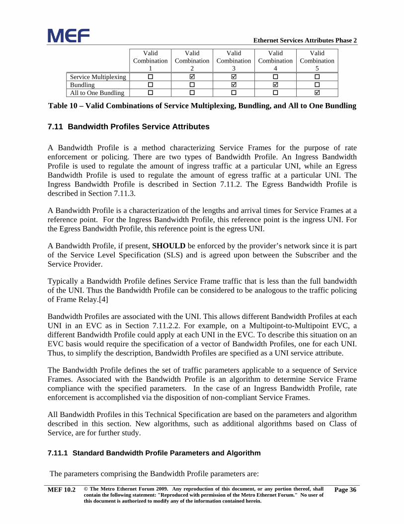
Ethernet Services Attributes Phase 2
MEF 10.2 © The Metro Ethernet Forum 2009. Any reproduction of this document, or any portion thereof, shall contain the following statement: "Reproduced with permission of the Metro Ethernet Forum." No user of this document is authorized to modify any of the information contained herein.
Page 36
Valid
Combination 1
Valid Combination
2
Valid Combination
3
Valid Combination
4
Valid Combination
5 Service Multiplexing Bundling All to One Bundling
Table 10 – Valid Combinations of Service Multiplexing, Bundling, and All to One Bundling
7.11 Bandwidth Profiles Service Attributes
A Bandwidth Profile is a method characterizing Service Frames for the purpose of rate enforcement or policing. There are two types of Bandwidth Profile. An Ingress Bandwidth Profile is used to regulate the amount of ingress traffic at a particular UNI, while an Egress Bandwidth Profile is used to regulate the amount of egress traffic at a particular UNI. The Ingress Bandwidth Profile is described in Section 7.11.2. The Egress Bandwidth Profile is described in Section 7.11.3.
A Bandwidth Profile is a characterization of the lengths and arrival times for Service Frames at a reference point. For the Ingress Bandwidth Profile, this reference point is the ingress UNI. For the Egress Bandwidth Profile, this reference point is the egress UNI.
A Bandwidth Profile, if present, SHOULD be enforced by the provider’s network since it is part of the Service Level Specification (SLS) and is agreed upon between the Subscriber and the Service Provider.
Typically a Bandwidth Profile defines Service Frame traffic that is less than the full bandwidth of the UNI. Thus the Bandwidth Profile can be considered to be analogous to the traffic policing of Frame Relay.[4]
Bandwidth Profiles are associated with the UNI. This allows different Bandwidth Profiles at each UNI in an EVC as in Section 7.11.2.2. For example, on a Multipoint-to-Multipoint EVC, a different Bandwidth Profile could apply at each UNI in the EVC. To describe this situation on an EVC basis would require the specification of a vector of Bandwidth Profiles, one for each UNI. Thus, to simplify the description, Bandwidth Profiles are specified as a UNI service attribute.
The Bandwidth Profile defines the set of traffic parameters applicable to a sequence of Service Frames. Associated with the Bandwidth Profile is an algorithm to determine Service Frame compliance with the specified parameters. In the case of an Ingress Bandwidth Profile, rate enforcement is accomplished via the disposition of non-compliant Service Frames.
All Bandwidth Profiles in this Technical Specification are based on the parameters and algorithm described in this section. New algorithms, such as additional algorithms based on Class of Service, are for further study.
7.11.1 Standard Bandwidth Profile Parameters and Algorithm
The parameters comprising the Bandwidth Profile parameters are:
Ethernet Services Attributes Phase 2
MEF 10.2 © The Metro Ethernet Forum 2009. Any reproduction of this document, or any portion thereof, shall contain the following statement: "Reproduced with permission of the Metro Ethernet Forum." No user of this document is authorized to modify any of the information contained herein.
Page 37
• Committed Information Rate (CIR) expressed as bits per second. CIR MUST be ≥ 0.
• Committed Burst Size (CBS) expressed as bytes. When CIR > 0, CBS MUST be greater than or equal to the largest Maximum Transmission Unit size among all of the EVCs that the Bandwidth Profile applies to. See Section 6.10.
• Excess Information Rate (EIR) expressed as bits per second. EIR MUST be ≥ 0.
• Excess Burst Size (EBS) expressed as bytes. When EIR > 0, EBS MUST be greater than or equal to the largest Maximum Transmission Unit size among all of the EVCs that the Bandwidth Profile applies to. See Section 6.10.
• Coupling Flag (CF) MUST have only one of two possible values, 0 or 1.
• Color Mode (CM) MUST have only one of two possible values, “color-blind” and “color-aware.”
Each Service Frame is classified to determine which, if any, Bandwidth Profile is applicable to the Service Frame.18 Operation of the Bandwidth Profile algorithm is governed by the six parameters, <CIR, CBS, EIR, EBS, CF, CM>. The algorithm declares each Service Frame to be compliant or non-compliant relative to the Bandwidth Profile. The level of compliance is expressed as one of three colors, Green, Yellow, or Red.19
The Bandwidth Profile algorithm is said to be in color aware mode when each Service Frame already has a level of compliance (i.e., a color) associated with it and that color is taken into account in determining the level of compliance by the Bandwidth Profile algorithm. The Bandwidth Profile algorithm is said to be in color blind mode when the color (if any) already associated with each Service Frame is ignored by the Bandwidth Profile Algorithm. Color blind mode support is REQUIRED for Bandwidth Profiles. Color aware mode is OPTIONAL for Bandwidth Profiles. The color mode of operation MUST be determined using the parameter CM.
Since the coupling Flag has negligible effect in color blind mode (CM = “color-blind”), a service definition that uses color blind operation MAY be defined without specifying the value of the coupling flag.
The Bandwidth Profile algorithm is shown in Figure 13. For a sequence of Service Frames, { } ,1,0,, jjjj ttjlt ≥≥ + with arrival times at the reference point jt and lengths jl , the level of compliance color assigned to each Service Frame MUST be defined according to the algorithm in Figure 13. For this algorithm, ( ) CBStBc =0 and ( ) EBStBe =0 . ( )tBc and ( )tBe can be viewed as the number of bytes in the Committed and Excess token buckets respectively at a given time t.
18 Recall that a Service Frame is defined as any Ethernet Frame transmitted across the UNI and thus a Layer 2 Control Protocol Ethernet frame is a Service Frame and thus can be subject to a Bandwidth Profile. 19 The categorization of a Service Frame does not imply any change to the content of the frame. Certain approaches to network implementation may “mark” frames internal to the MEN but such procedures are beyond the scope of this Technical Specification.

Ethernet Services Attributes Phase 2
MEF 10.2 © The Metro Ethernet Forum 2009. Any reproduction of this document, or any portion thereof, shall contain the following statement: "Reproduced with permission of the Metro Ethernet Forum." No user of this document is authorized to modify any of the information contained herein.
Page 38
Declare Service Frame RedDeclare Service Frame Red
( ) ( ) ( )
( ) ( ) ( )
( ) ( ) ( ) ( )
×+−×+=
−−×+=
−×+=
−−
−−
−−
jjjjeje
jjjcj
jjjcjc
tOCFttEIRtBEBStB
CBSttCIRtBtO
ttCIRtBCBStB
11
11
11
8,min
8,0max
8,min
( )1 at time arrives length of Frame Service ≥jtl jj
( )[( )]
( )( )jcj tBl
CM
≤==
==
ANDGreenFrameServiceOR
blind-color
( )[( )]
( )( )jej tBl
CM
≤=
==
ANDRed!FrameServiceOR
blind-color
( ) ( ) jjcjc ltBtB −=Green Frame Service Declare
( ) ( ) jjeje ltBtB −=Yellow Frame Service DeclareYes
Yes
No
No
Figure 13 – The Bandwidth Profile Algorithm
Note that the algorithm in Figure 13 does not define an implementation of any network equipment. In fact, since the behavior is described with real numbers for representing time, exactly implementing the behavior is theoretically impossible. However, an implementation should be such that over any time interval ],[ kj tt the amount of traffic declared green, WG and the amount of traffic declared yellow, WY are lower bounded below by the values:
( ) ( )jkjcG ttCIRtBW −×+≥8
( ) ( )jkjeY ttEIRtBW −×+≥8
provided that the traffic is greater than these values.
The Coupling Flag CF is set to either 0 or 1. The choice of the value for CF has the effect of controlling the volume of the Service Frames that are declared Yellow. When CF is set to 0, the long term average bit rate of Service Frames that are declared Yellow is bounded by EIR. When CF is set to 1, the long term average bit rate of Service Frames that are declared Yellow is bounded by CIR + EIR depending on volume of the offered Service Frames that are declared Green. In both cases the burst size of the Service Frames that are declared Yellow is bounded by EBS.
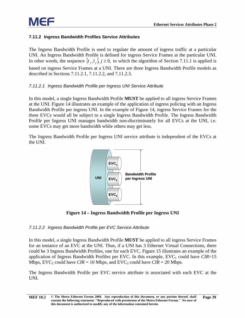
Ethernet Services Attributes Phase 2
MEF 10.2 © The Metro Ethernet Forum 2009. Any reproduction of this document, or any portion thereof, shall contain the following statement: "Reproduced with permission of the Metro Ethernet Forum." No user of this document is authorized to modify any of the information contained herein.
Page 39
7.11.2 Ingress Bandwidth Profiles Service Attributes
The Ingress Bandwidth Profile is used to regulate the amount of ingress traffic at a particular UNI. An Ingress Bandwidth Profile is defined for ingress Service Frames at the particular UNI. In other words, the sequence { } ,0,, ≥jlt jj to which the algorithm of Section 7.11.1 is applied is based on ingress Service Frames at a UNI. There are three Ingress Bandwidth Profile models as described in Sections 7.11.2.1, 7.11.2.2, and 7.11.2.3.
7.11.2.1 Ingress Bandwidth Profile per Ingress UNI Service Attribute
In this model, a single Ingress Bandwidth Profile MUST be applied to all ingress Service Frames at the UNI. Figure 14 illustrates an example of the application of ingress policing with an Ingress Bandwidth Profile per ingress UNI. In the example of Figure 14, ingress Service Frames for the three EVCs would all be subject to a single Ingress Bandwidth Profile. The Ingress Bandwidth Profile per Ingress UNI manages bandwidth non-discriminately for all EVCs at the UNI, i.e. some EVCs may get more bandwidth while others may get less.
The Ingress Bandwidth Profile per Ingress UNI service attribute is independent of the EVCs at the UNI.
UNIUNI
EVCEVC11
EVCEVC22
EVCEVC33
Bandwidth ProfileBandwidth Profileper Ingress UNIper Ingress UNI
Figure 14 – Ingress Bandwidth Profile per Ingress UNI
7.11.2.2 Ingress Bandwidth Profile per EVC Service Attribute
In this model, a single Ingress Bandwidth Profile MUST be applied to all ingress Service Frames for an instance of an EVC at the UNI. Thus, if a UNI has 3 Ethernet Virtual Connections, there could be 3 Ingress Bandwidth Profiles, one for each EVC. Figure 15 illustrates an example of the application of Ingress Bandwidth Profiles per EVC. In this example, EVC1 could have CIR=15 Mbps, EVC2 could have CIR = 10 Mbps, and EVC3 could have CIR = 20 Mbps.
The Ingress Bandwidth Profile per EVC service attribute is associated with each EVC at the UNI.

Ethernet Services Attributes Phase 2
MEF 10.2 © The Metro Ethernet Forum 2009. Any reproduction of this document, or any portion thereof, shall contain the following statement: "Reproduced with permission of the Metro Ethernet Forum." No user of this document is authorized to modify any of the information contained herein.
Page 40
UNIUNI
EVCEVC11
EVCEVC22
EVCEVC33
Bandwidth Bandwidth ProfileperProfileper EVCEVC11
Bandwidth Profile per EVCBandwidth Profile per EVC22
Bandwidth Profile per EVCBandwidth Profile per EVC33
Figure 15 – Ingress Bandwidth Profile per EVC
7.11.2.3 Ingress Bandwidth Profile per Class of Service Identifier Service Attribute
In this model, a single Ingress Bandwidth Profile MUST be applied to all ingress Service Frames with a specific Class of Service Identifier. Class of Service Identifiers are specified in Section 6.8. Refer to the example in Figure 16. In this example, there are three Class of Service Identifiers within EVC1, each with a separate Ingress Bandwidth Profile.
The Ingress Bandwidth Profile per Class of Service Identifier service attribute is associated with each EVC at the UNI.
UNIUNI
EVCEVC11
EVCEVC22
CECE--VLAN CoS 0,1,2,3VLAN CoS 0,1,2,3
CECE--VLAN CoS 4,5VLAN CoS 4,5
CECE--VLAN CoS 6,7VLAN CoS 6,7
Ingress Bandwidth Profile per CoS IDIngress Bandwidth Profile per CoS ID
Ingress Bandwidth Profile per CoS IDIngress Bandwidth Profile per CoS ID
Ingress Bandwidth Profile per CoS IDIngress Bandwidth Profile per CoS ID
Figure 16 – Ingress Bandwidth Profile per Class of Service Identifier
7.11.2.4 Simultaneous Application of the Ingress Bandwidth Profile Application Models
Multiple models of Ingress Bandwidth Profile application MAY exist simultaneously at a UNI. However, a UNI MUST be configured such that only a single Ingress Bandwidth Profile applies to any given ingress Service Frame. This means that:

Ethernet Services Attributes Phase 2
MEF 10.2 © The Metro Ethernet Forum 2009. Any reproduction of this document, or any portion thereof, shall contain the following statement: "Reproduced with permission of the Metro Ethernet Forum." No user of this document is authorized to modify any of the information contained herein.
Page 41
• If there is a per UNI Ingress Bandwidth Profile, then there cannot be any other Ingress Bandwidth Profiles at that UNI.
• If there is a per EVC Ingress Bandwidth Profile on an EVC, then there cannot be any per Class of Service Ingress Bandwidth Profiles for instances of CoS on that EVC.
For example, in the configuration of Figure 16, there cannot be an Ingress Bandwidth Profile for EVC1. Note also for the configuration in Figure 16, that it is possible to configure a per-EVC Ingress Bandwidth Profile for EVC2 but there happens to not be an Ingress Bandwidth Profile for EVC2 in this example.
7.11.2.5 Service Frame Disposition
The disposition of a given Service Frame with respect to delivery to an egress UNI is dependent on the Service Frame’s level of compliance to the Ingress Bandwidth Profile that is applied to it. This is called the Ingress Bandwidth Profile compliance level and it has three possible values: Green, Yellow, or Red. Table 11 defines how the Ingress Bandwidth Profile compliance is related to the disposition of the Service Frame. In this table, “Not Applied” identifies the case where no Ingress Bandwidth Profile was applied to the Service Frame in question.
The disposition of each Service Frame for delivery to each egress UNI MUST be as described in Table 11.
Ingress Bandwidth Profile Compliance Service Frame Disposition
Red Discard
Yellow Deliver to the egress UNI according to the Service Attributes of the service instance but SLS performance objectives do not apply.
Green Deliver to the egress UNI according to the Service Attributes of the service instance and SLS performance objectives apply. Not Applied
Table 11 –Service Frame Disposition for Each Egress UNI
The behavior described in Table 11 is based on the arrival of the Service Frame at its ingress UNI. It does not mandate or constrain in any way the implementation within the Service Provider network.
From Table 11 it is clear that the better the level of Ingress Bandwidth Profile compliance the better the performance of the service. In order to increase the level of Ingress Bandwidth Profile compliance a Subscriber may choose to shape traffic in the CE (see Section 10.3).
7.11.3 Egress Bandwidth Profiles Service Attributes
An Egress Bandwidth Profile is used to regulate the amount of egress traffic at a particular UNI. An Egress Bandwidth Profile is defined for a particular UNI and applies to all or a subset of all egress Service Frames at the UNI in question.
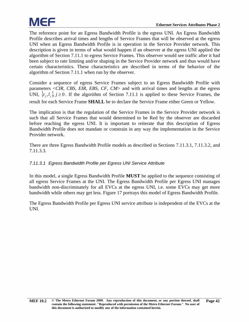
Ethernet Services Attributes Phase 2
MEF 10.2 © The Metro Ethernet Forum 2009. Any reproduction of this document, or any portion thereof, shall contain the following statement: "Reproduced with permission of the Metro Ethernet Forum." No user of this document is authorized to modify any of the information contained herein.
Page 42
The reference point for an Egress Bandwidth Profile is the egress UNI. An Egress Bandwidth Profile describes arrival times and lengths of Service Frames that will be observed at the egress UNI when an Egress Bandwidth Profile is in operation in the Service Provider network. This description is given in terms of what would happen if an observer at the egress UNI applied the algorithm of Section 7.11.1 to egress Service Frames. This observer would see traffic after it had been subject to rate limiting and/or shaping in the Service Provider network and thus would have certain characteristics. These characteristics are described in terms of the behavior of the algorithm of Section 7.11.1 when run by the observer.
Consider a sequence of egress Service Frames subject to an Egress Bandwidth Profile with parameters <CIR, CBS, EIR, EBS, CF, CM> and with arrival times and lengths at the egress UNI, { } 0,, ≥jlt jj . If the algorithm of Section 7.11.1 is applied to these Service Frames, the result for each Service Frame SHALL be to declare the Service Frame either Green or Yellow.
The implication is that the regulation of the Service Frames in the Service Provider network is such that all Service Frames that would determined to be Red by the observer are discarded before reaching the egress UNI. It is important to reiterate that this description of Egress Bandwidth Profile does not mandate or constrain in any way the implementation in the Service Provider network.
There are three Egress Bandwidth Profile models as described in Sections 7.11.3.1, 7.11.3.2, and 7.11.3.3.
7.11.3.1 Egress Bandwidth Profile per Egress UNI Service Attribute
In this model, a single Egress Bandwidth Profile MUST be applied to the sequence consisting of all egress Service Frames at the UNI. The Egress Bandwidth Profile per Egress UNI manages bandwidth non-discriminately for all EVCs at the egress UNI, i.e. some EVCs may get more bandwidth while others may get less. Figure 17 portrays this model of Egress Bandwidth Profile.
The Egress Bandwidth Profile per Egress UNI service attribute is independent of the EVCs at the UNI.
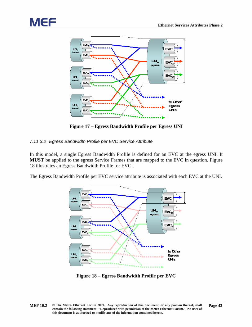
Ethernet Services Attributes Phase 2
MEF 10.2 © The Metro Ethernet Forum 2009. Any reproduction of this document, or any portion thereof, shall contain the following statement: "Reproduced with permission of the Metro Ethernet Forum." No user of this document is authorized to modify any of the information contained herein.
Page 43
Figure 17 – Egress Bandwidth Profile per Egress UNI
7.11.3.2 Egress Bandwidth Profile per EVC Service Attribute
In this model, a single Egress Bandwidth Profile is defined for an EVC at the egress UNI. It MUST be applied to the egress Service Frames that are mapped to the EVC in question. Figure 18 illustrates an Egress Bandwidth Profile for EVC1.
The Egress Bandwidth Profile per EVC service attribute is associated with each EVC at the UNI.
Figure 18 – Egress Bandwidth Profile per EVC
Ethernet Services Attributes Phase 2
MEF 10.2 © The Metro Ethernet Forum 2009. Any reproduction of this document, or any portion thereof, shall contain the following statement: "Reproduced with permission of the Metro Ethernet Forum." No user of this document is authorized to modify any of the information contained herein.
Page 44
7.11.3.3 Egress Bandwidth Profile per Class of Service Identifier Service Attribute
In this model, a single Egress Bandwidth Profile is defined for a specific Class of Service Identifier that is defined at the egress UNI. It MUST be applied to the egress Service Frames with the Class of Service Identifier in question. As an example, consider an Egress UNI with two EVCs with each EVC having 3 Class of Service Identifiers. With this model, there can be up to six Egress Bandwidth Profiles.
The Egress Bandwidth Profile per Class of Service Identifier service attribute is associated with each EVC at the UNI.
7.11.3.4 Simultaneous Application of the Egress Bandwidth Profile Application Models
Multiple models of Egress Bandwidth Profile application MAY exist simultaneously for an egress UNI. However, an egress Service Frame MUST be subject to at most one Egress Bandwidth Profile. This means that:
• If there is a per UNI Egress Bandwidth Profile, then there cannot be any other Egress Bandwidth Profiles at that UNI.
• If there is a per EVC Egress Bandwidth Profile on an EVC, then there cannot be any per Class of Service Egress Bandwidth Profiles for instances of CoS on that EVC.
7.12 Security
The Ethernet Virtual Connection is the fundamental service construct that defines how the separation between Subscribers’ traffic is maintained. Additional security constructs and service attributes may be addressed in subsequent phases of this Technical Specification.
7.13 UNI Layer 2 Control Protocol Processing Service Attribute
There are four alternatives for processing a given Layer 2 Control Protocol (see Table 1) at a UNI as described in the following subsections. The UNI Layer 2 Control Protocol Processing service attribute is independent of the EVCs at the UNI.
7.13.1 Discard
When this alternative is in force, the MEN MUST discard all ingress Service Frames carrying the Layer 2 Control Protocol and the MEN MUST NOT generate any egress Service Frames carrying the Layer 2 Control Protocol. Note that when this alternative is in force for the Layer 2 Control Protocol, the Layer 2 Control Protocol cannot be processed by an EVC. See Section 6.7.
Ethernet Services Attributes Phase 2
MEF 10.2 © The Metro Ethernet Forum 2009. Any reproduction of this document, or any portion thereof, shall contain the following statement: "Reproduced with permission of the Metro Ethernet Forum." No user of this document is authorized to modify any of the information contained herein.
Page 45
7.13.2 Peer
When this alternative is in force, the MEN MUST act as a peer of the CE in the operation of the Layer 2 Control Protocol. From the CE point of view, the MEN is a single device that is running the Layer 2 Control Protocol.
7.13.3 Pass to EVC
When this alternative is in force, the disposition of the Layer 2 Control Protocol MUST be determined by the Layer 2 Control Protocol Processing attribute of the EVC (tunneled or discarded). The EVC associated with Layer 2 Control Protocol is determined by the CE-VLAN ID of the Service Frame and CE-VLAN ID/EVC Map. See Section 6.7.
7.13.4 Peer and Pass to EVC
When this alternative is in force, some Service Frames carrying the Layer 2 Control Protocol are processed by the MEN as a peer while other Service Frames carrying the Layer 2 Control Protocol are passed to the EVC. The method for identifying that a Service Frame is to be peered or passed to the EVC MUST be specified for each service. As an example, different destination MAC addresses might be used to indicate the handling of a Service Frame carrying the Layer 2 Control Protocol.
8. Ethernet Service Framework
The Ethernet service framework provides the definition and relationship between attributes and their associated parameters used to create an Ethernet Service. An Ethernet Service consists of (Refer to Figure 19):
• One Ethernet Service Type,
• One or more Ethernet Service Attributes and
• One or more parameter values associated with each Ethernet Service Attribute.
The Service Framework associates a service with the UNI characteristics at which the Service is offered to the Subscriber and with the EVC supporting the service. The Ethernet Service Attributes are what define the UNI and EVC characteristics.
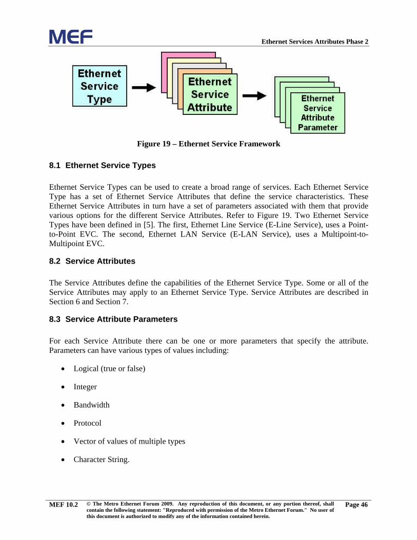
Ethernet Services Attributes Phase 2
MEF 10.2 © The Metro Ethernet Forum 2009. Any reproduction of this document, or any portion thereof, shall contain the following statement: "Reproduced with permission of the Metro Ethernet Forum." No user of this document is authorized to modify any of the information contained herein.
Page 46
Figure 19 – Ethernet Service Framework
8.1 Ethernet Service Types
Ethernet Service Types can be used to create a broad range of services. Each Ethernet Service Type has a set of Ethernet Service Attributes that define the service characteristics. These Ethernet Service Attributes in turn have a set of parameters associated with them that provide various options for the different Service Attributes. Refer to Figure 19. Two Ethernet Service Types have been defined in [5]. The first, Ethernet Line Service (E-Line Service), uses a Point-to-Point EVC. The second, Ethernet LAN Service (E-LAN Service), uses a Multipoint-to-Multipoint EVC.
8.2 Service Attributes
The Service Attributes define the capabilities of the Ethernet Service Type. Some or all of the Service Attributes may apply to an Ethernet Service Type. Service Attributes are described in Section 6 and Section 7.
8.3 Service Attribute Parameters
For each Service Attribute there can be one or more parameters that specify the attribute. Parameters can have various types of values including:
• Logical (true or false)
• Integer
• Bandwidth
• Protocol
• Vector of values of multiple types
• Character String.
Ethernet Services Attributes Phase 2
MEF 10.2 © The Metro Ethernet Forum 2009. Any reproduction of this document, or any portion thereof, shall contain the following statement: "Reproduced with permission of the Metro Ethernet Forum." No user of this document is authorized to modify any of the information contained herein.
Page 47
8.4 Ethernet Service Framework Summary
For a particular Ethernet Service Type, there are two types of Service Attributes, those that apply to a UNI as described in Section 7 and those that apply to an EVC as described in Section 6. The UNI and EVC per UNI Service Attributes are listed in Table 12 along with the type of parameter value for the attribute. For a given instance of a service, a table like that of Table 12 MUST be specified for each UNI in the EVC associated with the service.
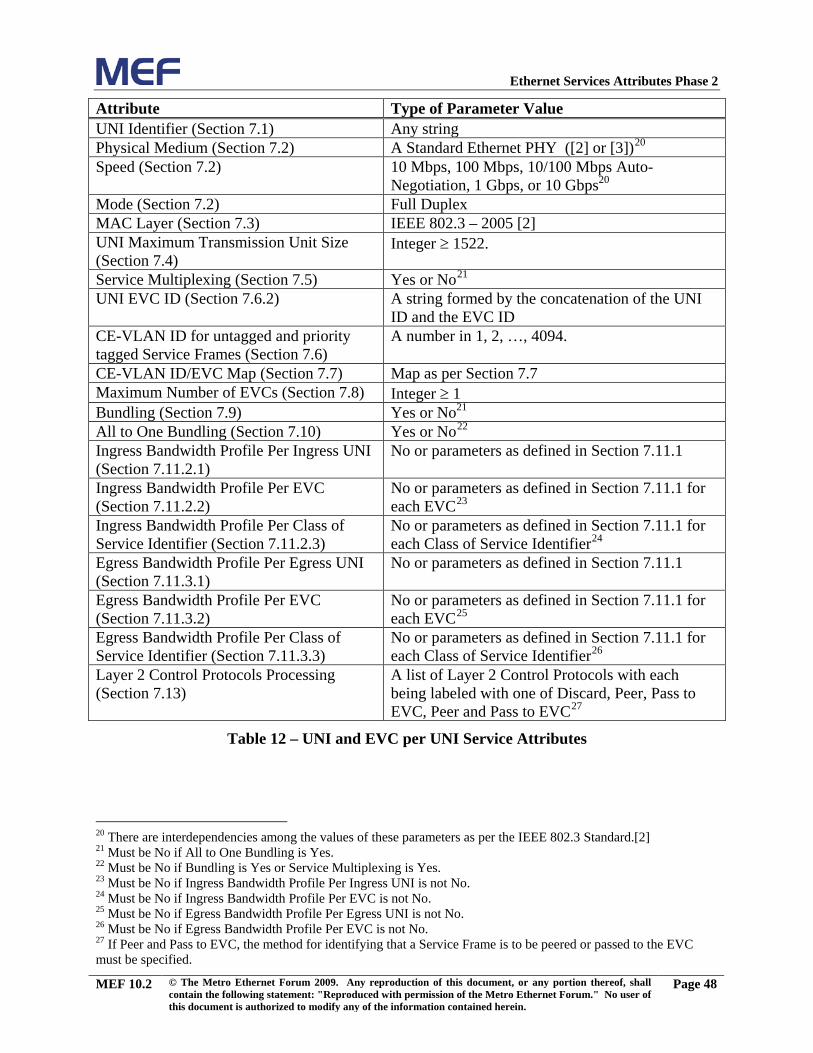
Ethernet Services Attributes Phase 2
MEF 10.2 © The Metro Ethernet Forum 2009. Any reproduction of this document, or any portion thereof, shall contain the following statement: "Reproduced with permission of the Metro Ethernet Forum." No user of this document is authorized to modify any of the information contained herein.
Page 48
Attribute Type of Parameter Value UNI Identifier (Section 7.1) Any string Physical Medium (Section 7.2) A Standard Ethernet PHY ([2] or [3])20 Speed (Section 7.2) 10 Mbps, 100 Mbps, 10/100 Mbps Auto-
Negotiation, 1 Gbps, or 10 Gbps20 Mode (Section 7.2) Full Duplex MAC Layer (Section 7.3) IEEE 802.3 – 2005 [2] UNI Maximum Transmission Unit Size (Section 7.4)
Integer ≥ 1522.
Service Multiplexing (Section 7.5) Yes or No21 UNI EVC ID (Section 7.6.2) A string formed by the concatenation of the UNI
ID and the EVC ID CE-VLAN ID for untagged and priority tagged Service Frames (Section 7.6)
A number in 1, 2, …, 4094.
CE-VLAN ID/EVC Map (Section 7.7) Map as per Section 7.7 Maximum Number of EVCs (Section 7.8) Integer ≥ 1 Bundling (Section 7.9) Yes or No21 All to One Bundling (Section 7.10) Yes or No22 Ingress Bandwidth Profile Per Ingress UNI (Section 7.11.2.1)
No or parameters as defined in Section 7.11.1
Ingress Bandwidth Profile Per EVC (Section 7.11.2.2)
No or parameters as defined in Section 7.11.1 for each EVC23
Ingress Bandwidth Profile Per Class of Service Identifier (Section 7.11.2.3)
No or parameters as defined in Section 7.11.1 for each Class of Service Identifier24
Egress Bandwidth Profile Per Egress UNI (Section 7.11.3.1)
No or parameters as defined in Section 7.11.1
Egress Bandwidth Profile Per EVC (Section 7.11.3.2)
No or parameters as defined in Section 7.11.1 for each EVC25
Egress Bandwidth Profile Per Class of Service Identifier (Section 7.11.3.3)
No or parameters as defined in Section 7.11.1 for each Class of Service Identifier26
Layer 2 Control Protocols Processing (Section 7.13)
A list of Layer 2 Control Protocols with each being labeled with one of Discard, Peer, Pass to EVC, Peer and Pass to EVC27
Table 12 – UNI and EVC per UNI Service Attributes
20 There are interdependencies among the values of these parameters as per the IEEE 802.3 Standard.[2] 21 Must be No if All to One Bundling is Yes. 22 Must be No if Bundling is Yes or Service Multiplexing is Yes. 23 Must be No if Ingress Bandwidth Profile Per Ingress UNI is not No. 24 Must be No if Ingress Bandwidth Profile Per EVC is not No. 25 Must be No if Egress Bandwidth Profile Per Egress UNI is not No. 26 Must be No if Egress Bandwidth Profile Per EVC is not No. 27 If Peer and Pass to EVC, the method for identifying that a Service Frame is to be peered or passed to the EVC must be specified.
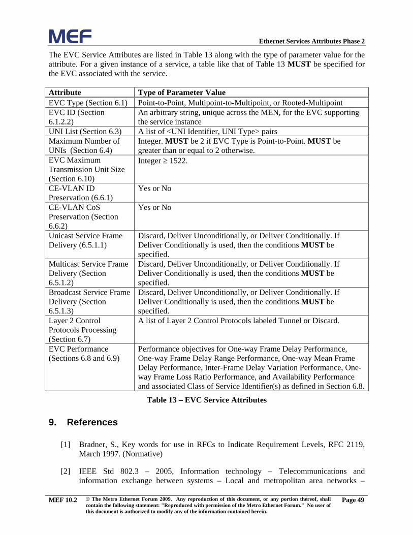
Ethernet Services Attributes Phase 2
MEF 10.2 © The Metro Ethernet Forum 2009. Any reproduction of this document, or any portion thereof, shall contain the following statement: "Reproduced with permission of the Metro Ethernet Forum." No user of this document is authorized to modify any of the information contained herein.
Page 49
The EVC Service Attributes are listed in Table 13 along with the type of parameter value for the attribute. For a given instance of a service, a table like that of Table 13 MUST be specified for the EVC associated with the service. Attribute Type of Parameter Value EVC Type (Section 6.1) Point-to-Point, Multipoint-to-Multipoint, or Rooted-Multipoint EVC ID (Section 6.1.2.2)
An arbitrary string, unique across the MEN, for the EVC supporting the service instance
UNI List (Section 6.3) A list of <UNI Identifier, UNI Type> pairs Maximum Number of UNIs (Section 6.4)
Integer. MUST be 2 if EVC Type is Point-to-Point. MUST be greater than or equal to 2 otherwise.
EVC Maximum Transmission Unit Size (Section 6.10)
Integer ≥ 1522.
CE-VLAN ID Preservation (6.6.1)
Yes or No
CE-VLAN CoS Preservation (Section 6.6.2)
Yes or No
Unicast Service Frame Delivery (6.5.1.1)
Discard, Deliver Unconditionally, or Deliver Conditionally. If Deliver Conditionally is used, then the conditions MUST be specified.
Multicast Service Frame Delivery (Section 6.5.1.2)
Discard, Deliver Unconditionally, or Deliver Conditionally. If Deliver Conditionally is used, then the conditions MUST be specified.
Broadcast Service Frame Delivery (Section 6.5.1.3)
Discard, Deliver Unconditionally, or Deliver Conditionally. If Deliver Conditionally is used, then the conditions MUST be specified.
Layer 2 Control Protocols Processing (Section 6.7)
A list of Layer 2 Control Protocols labeled Tunnel or Discard.
EVC Performance (Sections 6.8 and 6.9)
Performance objectives for One-way Frame Delay Performance, One-way Frame Delay Range Performance, One-way Mean Frame Delay Performance, Inter-Frame Delay Variation Performance, One-way Frame Loss Ratio Performance, and Availability Performance and associated Class of Service Identifier(s) as defined in Section 6.8.
Table 13 – EVC Service Attributes
9. References
[1] Bradner, S., Key words for use in RFCs to Indicate Requirement Levels, RFC 2119, March 1997. (Normative)
[2] IEEE Std 802.3 – 2005, Information technology – Telecommunications and information exchange between systems – Local and metropolitan area networks –
Ethernet Services Attributes Phase 2
MEF 10.2 © The Metro Ethernet Forum 2009. Any reproduction of this document, or any portion thereof, shall contain the following statement: "Reproduced with permission of the Metro Ethernet Forum." No user of this document is authorized to modify any of the information contained herein.
Page 50
Specific requirements – Part 3: Carrier sense multiple access with collision detection (CSMA/CD) access method and physical layer specifications, 9 December 2005. (Normative)
[3] IEEE Std 802.3ae – 2002, IEEE Standard for Information technology – Telecommunications and information exchange between systems – Local and metropolitan area networks – Specific requirements – Part 3: Carrier Sense Multiple Access with Collision Detection (CSMA/CD) Access Method and Physical Layer Specifications Amendment: Media Access Control (MAC) Parameters, Physical Layers, and Management Parameters for 10 Gb/s Operation, 13 June 2002. (Normative)
[4] International Telecommunication Union, Recommendation I.370, Integrated Services Digital Network (ISDN), Overall Network Aspects And Functions, ISDN User-Network Interfaces, Congestion Management For The ISDN Frame Relaying Bearer Service, 1991.
[5] Metro Ethernet Forum, MEF 6, Ethernet Services Definitions - Phase 1, June 2004.
[6] C. Demichelis and P. Chimento, IP Packet Delay Variation Metric for IP Performance Metric (IPPM), RFC 3393, November 2002.
[7] Metro Ethernet Forum MEF 10, Ethernet Services Attributes Phase 1, November 2004.
[8] IEEE Std 802.1D – 2004, IEEE Standard for Local and Metropolitan Area Networks: Media Access Control (MAC) Bridges, June 2004.
[9] IEEE Std 802.1Q – 2003, IEEE Standards for Local and metropolitan area networks—Virtual Bridged Local Area Networks, 7 May 2003.
[10] IEEE Std 802.1ad – 2005, IEEE Standard for Local and Metropolitan Area Networks— Virtual Bridged Local Area Networks — Amendment 4: Provider Bridges, May 2006.
[11] Metro Ethernet Forum MEF 16, Ethernet Local Management Interface (E-LMI), January 2006.
[12] Metro Ethernet Forum MEF 7, EMS-NMS Information Model, October 2004.
[13] Metro Ethernet Forum MEF 10.1, Ethernet Services Attributes Phase 2, November 2006.
10. Appendix (Informative)
This appendix contains examples of some of the attributes specified in this Technical Specification. They are for illustrative purposes only. In the event of a conflict between the material in this appendix and the main body of this text, the material in the main body is controlling.
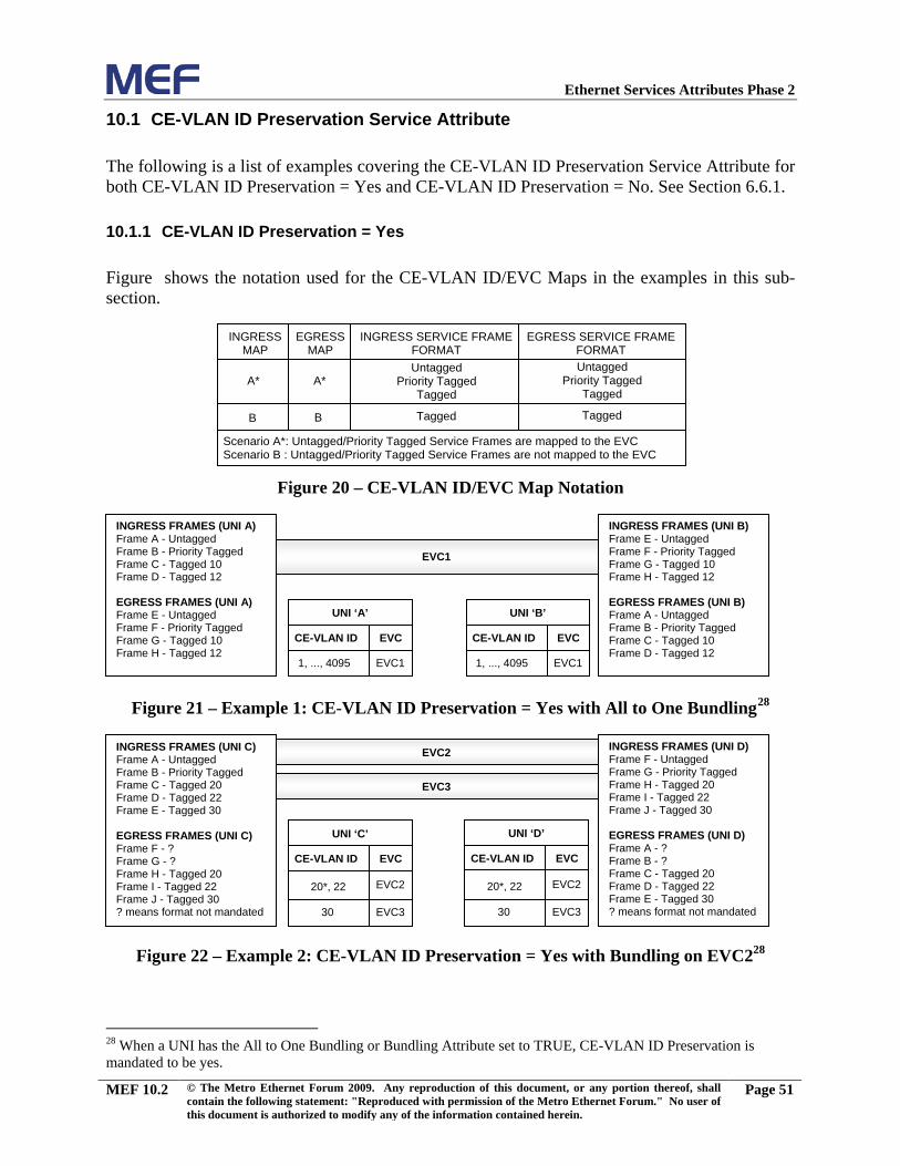
Ethernet Services Attributes Phase 2
MEF 10.2 © The Metro Ethernet Forum 2009. Any reproduction of this document, or any portion thereof, shall contain the following statement: "Reproduced with permission of the Metro Ethernet Forum." No user of this document is authorized to modify any of the information contained herein.
Page 51
10.1 CE-VLAN ID Preservation Service Attribute
The following is a list of examples covering the CE-VLAN ID Preservation Service Attribute for both CE-VLAN ID Preservation = Yes and CE-VLAN ID Preservation = No. See Section 6.6.1.
10.1.1 CE-VLAN ID Preservation = Yes
Figure shows the notation used for the CE-VLAN ID/EVC Maps in the examples in this sub-section.
Figure 20 – CE-VLAN ID/EVC Map Notation
Figure 21 – Example 1: CE-VLAN ID Preservation = Yes with All to One Bundling28
Figure 22 – Example 2: CE-VLAN ID Preservation = Yes with Bundling on EVC228
28 When a UNI has the All to One Bundling or Bundling Attribute set to TRUE, CE-VLAN ID Preservation is mandated to be yes.
INGRESS MAP
EGRESS MAP
INGRESS SERVICE FRAME FORMAT
EGRESS SERVICE FRAME FORMAT
Untagged Priority Tagged
Tagged
Untagged Priority Tagged
Tagged
Tagged Tagged
A* A*
B B
Scenario A*: Untagged/Priority Tagged Service Frames are mapped to the EVC Scenario B : Untagged/Priority Tagged Service Frames are not mapped to the EVC
INGRESS FRAMES (UNI A) Frame A - Untagged Frame B - Priority Tagged Frame C - Tagged 10 Frame D - Tagged 12 EGRESS FRAMES (UNI A) Frame E - Untagged Frame F - Priority Tagged Frame G - Tagged 10 Frame H - Tagged 12
UNI ‘A’
CE-VLAN ID EVC
1, ..., 4095 EVC1
INGRESS FRAMES (UNI B) Frame E - Untagged Frame F - Priority Tagged Frame G - Tagged 10 Frame H - Tagged 12 EGRESS FRAMES (UNI B) Frame A - Untagged Frame B - Priority Tagged Frame C - Tagged 10 Frame D - Tagged 12
UNI ‘B’
CE-VLAN ID EVC
1, ..., 4095 EVC1
EVC1
INGRESS FRAMES (UNI C) Frame A - Untagged Frame B - Priority Tagged Frame C - Tagged 20 Frame D - Tagged 22 Frame E - Tagged 30 EGRESS FRAMES (UNI C) Frame F - ? Frame G - ? Frame H - Tagged 20 Frame I - Tagged 22 Frame J - Tagged 30 ? means format not mandated
UNI ‘C’
CE-VLAN ID EVC
EVC2
EVC3
INGRESS FRAMES (UNI D) Frame F - Untagged Frame G - Priority Tagged Frame H - Tagged 20 Frame I - Tagged 22 Frame J - Tagged 30 EGRESS FRAMES (UNI D) Frame A - ? Frame B - ? Frame C - Tagged 20 Frame D - Tagged 22 Frame E - Tagged 30 ? means format not mandated
EVC2
EVC3
20*, 22
30
UNI ‘D’
CE-VLAN ID EVC
EVC2
EVC3
20*, 22
30
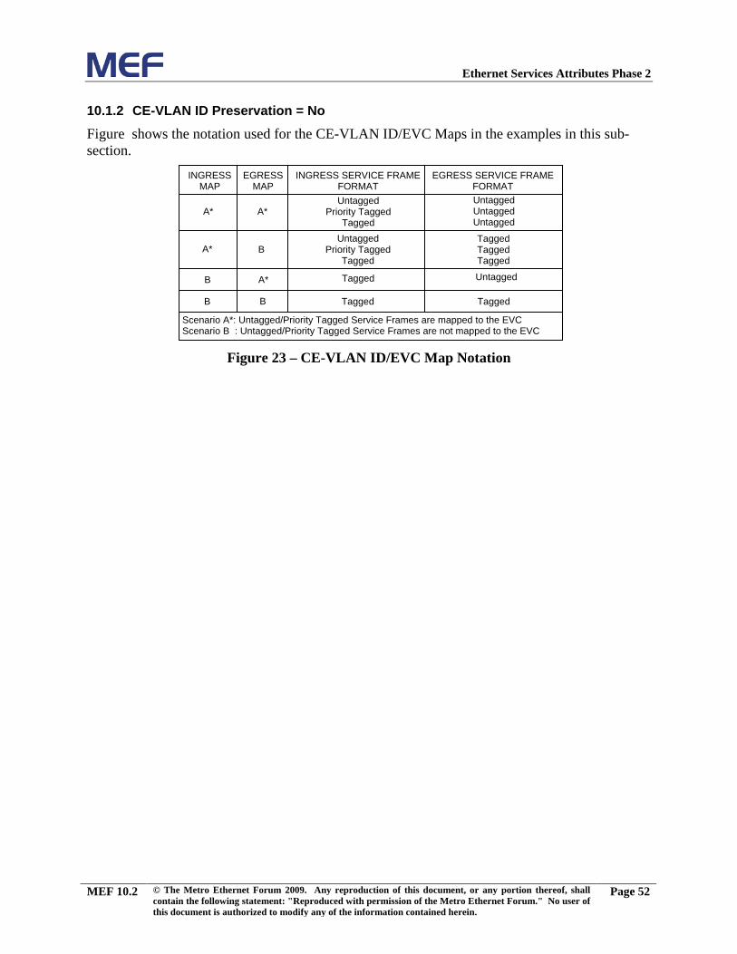
Ethernet Services Attributes Phase 2
MEF 10.2 © The Metro Ethernet Forum 2009. Any reproduction of this document, or any portion thereof, shall contain the following statement: "Reproduced with permission of the Metro Ethernet Forum." No user of this document is authorized to modify any of the information contained herein.
Page 52
10.1.2 CE-VLAN ID Preservation = No
Figure shows the notation used for the CE-VLAN ID/EVC Maps in the examples in this sub-section.
Figure 23 – CE-VLAN ID/EVC Map Notation
INGRESS MAP
EGRESS MAP
INGRESS SERVICE FRAME FORMAT
EGRESS SERVICE FRAME FORMAT
Untagged Priority Tagged
Tagged
Untagged Untagged Untagged
Tagged Untagged
A* A*
B
B
Scenario A*: Untagged/Priority Tagged Service Frames are mapped to the EVC Scenario B : Untagged/Priority Tagged Service Frames are not mapped to the EVC
Untagged Priority Tagged
Tagged
Tagged Tagged Tagged
A*
A*
B B Tagged Tagged
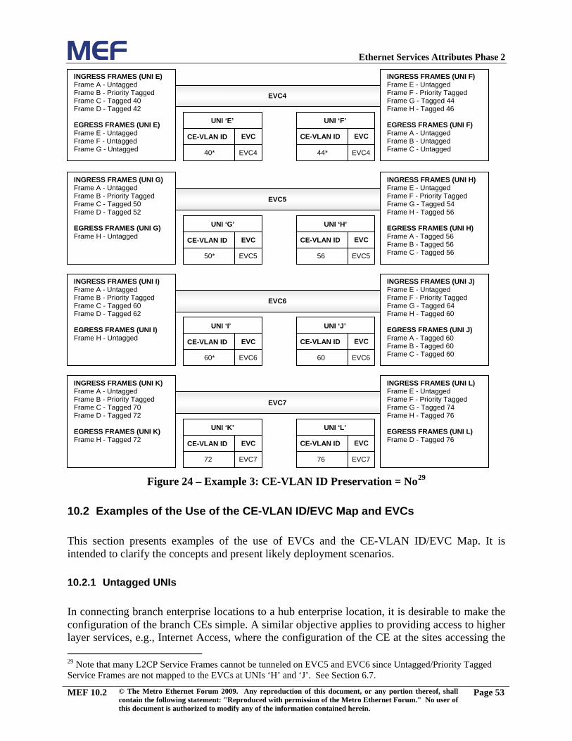
Ethernet Services Attributes Phase 2
MEF 10.2 © The Metro Ethernet Forum 2009. Any reproduction of this document, or any portion thereof, shall contain the following statement: "Reproduced with permission of the Metro Ethernet Forum." No user of this document is authorized to modify any of the information contained herein.
Page 53
Figure 24 – Example 3: CE-VLAN ID Preservation = No29
10.2 Examples of the Use of the CE-VLAN ID/EVC Map and EVCs
This section presents examples of the use of EVCs and the CE-VLAN ID/EVC Map. It is intended to clarify the concepts and present likely deployment scenarios.
10.2.1 Untagged UNIs
In connecting branch enterprise locations to a hub enterprise location, it is desirable to make the configuration of the branch CEs simple. A similar objective applies to providing access to higher layer services, e.g., Internet Access, where the configuration of the CE at the sites accessing the 29 Note that many L2CP Service Frames cannot be tunneled on EVC5 and EVC6 since Untagged/Priority Tagged Service Frames are not mapped to the EVCs at UNIs ‘H’ and ‘J’. See Section 6.7.
INGRESS FRAMES (UNI E) Frame A - Untagged Frame B - Priority Tagged Frame C - Tagged 40 Frame D - Tagged 42 EGRESS FRAMES (UNI E) Frame E - Untagged Frame F - Untagged Frame G - Untagged
UNI ‘E’
CE-VLAN ID EVC
40* EVC4
INGRESS FRAMES (UNI F) Frame E - Untagged Frame F - Priority Tagged Frame G - Tagged 44 Frame H - Tagged 46 EGRESS FRAMES (UNI F) Frame A - Untagged Frame B - Untagged Frame C - Untagged
UNI ‘F’
CE-VLAN ID EVC
44* EVC4
EVC4
INGRESS FRAMES (UNI G) Frame A - Untagged Frame B - Priority Tagged Frame C - Tagged 50 Frame D - Tagged 52 EGRESS FRAMES (UNI G) Frame H - Untagged
UNI ‘G’
CE-VLAN ID EVC
50* EVC5
INGRESS FRAMES (UNI H) Frame E - Untagged Frame F - Priority Tagged Frame G - Tagged 54 Frame H - Tagged 56 EGRESS FRAMES (UNI H) Frame A - Tagged 56 Frame B - Tagged 56 Frame C - Tagged 56
UNI ‘H’
CE-VLAN ID EVC
56 EVC5
EVC5
INGRESS FRAMES (UNI I) Frame A - Untagged Frame B - Priority Tagged Frame C - Tagged 60 Frame D - Tagged 62 EGRESS FRAMES (UNI I) Frame H - Untagged
UNI ‘I’
CE-VLAN ID EVC
60* EVC6
INGRESS FRAMES (UNI J) Frame E - Untagged Frame F - Priority Tagged Frame G - Tagged 64 Frame H - Tagged 60 EGRESS FRAMES (UNI J) Frame A - Tagged 60 Frame B - Tagged 60 Frame C - Tagged 60
UNI ‘J’
CE-VLAN ID EVC
60 EVC6
EVC6
INGRESS FRAMES (UNI K) Frame A - Untagged Frame B - Priority Tagged Frame C - Tagged 70 Frame D - Tagged 72 EGRESS FRAMES (UNI K) Frame H - Tagged 72
UNI ‘K’
CE-VLAN ID EVC
72 EVC7
INGRESS FRAMES (UNI L) Frame E - Untagged Frame F - Priority Tagged Frame G - Tagged 74 Frame H - Tagged 76 EGRESS FRAMES (UNI L) Frame D - Tagged 76
UNI ‘L’
CE-VLAN ID EVC
76 EVC7
EVC7
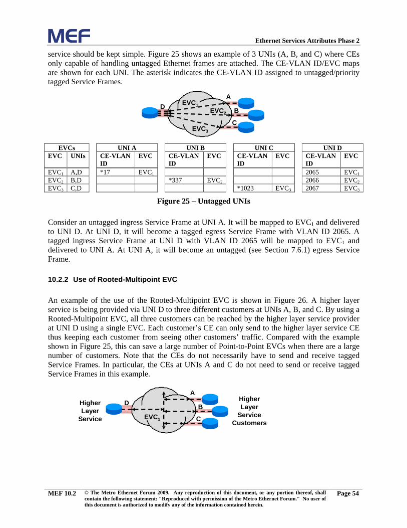
Ethernet Services Attributes Phase 2
MEF 10.2 © The Metro Ethernet Forum 2009. Any reproduction of this document, or any portion thereof, shall contain the following statement: "Reproduced with permission of the Metro Ethernet Forum." No user of this document is authorized to modify any of the information contained herein.
Page 54
service should be kept simple. Figure 25 shows an example of 3 UNIs (A, B, and C) where CEs only capable of handling untagged Ethernet frames are attached. The CE-VLAN ID/EVC maps are shown for each UNI. The asterisk indicates the CE-VLAN ID assigned to untagged/priority tagged Service Frames.
EVC1
EVC3
EVC2
A
B
C
D
EVCs UNI A UNI B UNI C UNI D
EVC UNIs CE-VLAN ID
EVC CE-VLAN ID
EVC CE-VLAN ID
EVC CE-VLAN ID
EVC
EVC1 A,D *17 EVC1 2065 EVC1 EVC2 B,D *337 EVC2 2066 EVC2 EVC3 C,D *1023 EVC3 2067 EVC3
Figure 25 – Untagged UNIs
Consider an untagged ingress Service Frame at UNI A. It will be mapped to EVC1 and delivered to UNI D. At UNI D, it will become a tagged egress Service Frame with VLAN ID 2065. A tagged ingress Service Frame at UNI D with VLAN ID 2065 will be mapped to EVC1 and delivered to UNI A. At UNI A, it will become an untagged (see Section 7.6.1) egress Service Frame.
10.2.2 Use of Rooted-Multipoint EVC
An example of the use of the Rooted-Multipoint EVC is shown in Figure 26. A higher layer service is being provided via UNI D to three different customers at UNIs A, B, and C. By using a Rooted-Multipoint EVC, all three customers can be reached by the higher layer service provider at UNI D using a single EVC. Each customer’s CE can only send to the higher layer service CE thus keeping each customer from seeing other customers’ traffic. Compared with the example shown in Figure 25, this can save a large number of Point-to-Point EVCs when there are a large number of customers. Note that the CEs do not necessarily have to send and receive tagged Service Frames. In particular, the CEs at UNIs A and C do not need to send or receive tagged Service Frames in this example.
A
B
C
D
EVC1
HigherLayer
Service
HigherLayer
ServiceCustomers

Ethernet Services Attributes Phase 2
MEF 10.2 © The Metro Ethernet Forum 2009. Any reproduction of this document, or any portion thereof, shall contain the following statement: "Reproduced with permission of the Metro Ethernet Forum." No user of this document is authorized to modify any of the information contained herein.
Page 55
EVCs UNI A UNI B UNI C UNI D EVC UNIs CE-VLAN ID EVC CE-VLAN ID EVC CE-VLAN ID EVC CE-VLAN ID EVC EVC1 A (Leaf)
B (Leaf) C (Leaf) D (Root)
*17 EVC1 3379 EVC1 *1023 EVC1 2065 EVC1
Figure 26 – Use of a Rooted-Multipoint EVC
10.2.3 Redundant Higher Layer Service Access
The example shown in Figure 27 illustrates the use of service multiplexing and Multipoint-to-Multipoint EVCs to provide redundant access to higher layer services. A Multipoint-to-Multipoint EVC is used for each customer of the higher layer service. Higher layer service routers are attached to two UNIs (C and D in the example) in each such EVC. Routing protocols running among the two higher layer service routers and the customer router allow the customer to access the higher layer service in a redundant fashion.
A
BD
EVC1HigherLayer
Service
HigherLayer
ServiceCustomers
C
EVC2
EVCs UNI A UNI B UNI C UNI D
EVC UNIs CE-VLAN ID EVC CE-VLAN ID EVC CE-VLAN ID EVC CE-VLAN ID EVC EVC1 A,C,D 2881 EVC1 124 EVC1 2065 EVC1 EVC2 B,C,D 3379 EVC2 125 EVC2 2066 EVC2
Figure 27 – Redundant Higher Layer Service Access
10.3 Traffic Shaping
Shaping is a procedure to reduce the burstiness of traffic. When done in the CE it is meant to increase the level of Ingress Bandwidth Profile compliance (see Section 7.11.2.5). A shaper is defined by a set of parameters. Those parameters should be chosen to ensure that the delay introduced by shaping function is bounded within the acceptable limits and that the traffic dropped at the shaper is kept to a minimum.
A shaper could be a single rate or a double rate shaper. A single rate shaper could consist of three parameters CIR, CBS*, and CBS, in which:
• CIR = the shaping rate of Green packets (average output rate of the shaper),
• CBS = the shaping burst of Green packets (maximum output burst of the shaper)
• CBS* = the accepted burst of Green packets (maximum buffer size for Green packets)

Ethernet Services Attributes Phase 2
MEF 10.2 © The Metro Ethernet Forum 2009. Any reproduction of this document, or any portion thereof, shall contain the following statement: "Reproduced with permission of the Metro Ethernet Forum." No user of this document is authorized to modify any of the information contained herein.
Page 56
• CBS* ≥ CBS, which means the shaper accepts larger burst at its input and generates smaller bursts at its output.
A double rate shaper could consist of parameters CIR, CBS*, CBS, EIR, EBS*, and EBS, in which, CIR, CBS*, and CBS are as defined above, and EIR, EBS*, and EBS are:
• EIR = the shaping rate of Yellow packets (average output rate of the shaper),
• EBS = the shaping burst of Yellow packets (maximum output burst of the shaper)
• EBS* = the accepted burst of Yellow packets (maximum buffer size for Yellow packets)
• EBS* ≥ EBS, which means the shaper accepts larger burst at its input and generates smaller bursts at its output.
It is recommended that the CE shape the traffic it sends into the MEN, so that the output of the shaper matches the CIR, CBS, EIR, and EBS parameters of the appropriate Bandwidth Profile.
For example, the CE could shape with a dual rate token bucket shaper using parameters CIR, CBS*, CBS, EIR, EBS*, and EBS where EBS* = 0 and CBS* is the shaper’s buffer size. Define the following notation:
• B(t) = the instantaneous buffer occupancy in bytes,
• C(t) = the instantaneous value of the tokens in the Committed token bucket,
• E(t) = the instantaneous value of the tokens in the Excess token bucket,
• L = the length of the frame at the head of the buffer, and
• THS = a configured buffer threshold such that the difference between THS and the shaper’s buffer size, CBS*, is large enough to hold a maximum sized frame.
Example shaping algorithms are presented below. The algorithm in Figure 28 is run every ∆t seconds where ∆t is the period between updating the token bucket values C(t) and E(t), i.e., C(t) = C(t) + CIR∆t and E(t) = E(t) + EIR∆t. Service Frames sent by the CE using this algorithm should always have an Ingress Bandwidth Profile compliance of Green. while((L <= C(t)) && (B(t) > 0)) { C(t) = C(t) – L; transmit the frame at the head of the buffer; //Should be declared green }
Figure 28 – Periodic Algorithm
The algorithm of Figure 29 is run every time a new frame is given to the shaper to process. This algorithm will send Service Frames with an Ingress Bandwidth Profile compliance of Yellow if necessary to try to make room in the buffer for the new frame.
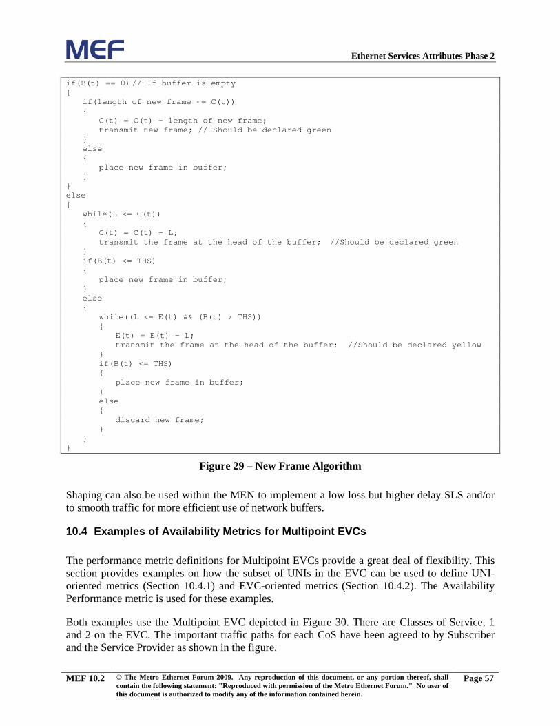
Ethernet Services Attributes Phase 2
MEF 10.2 © The Metro Ethernet Forum 2009. Any reproduction of this document, or any portion thereof, shall contain the following statement: "Reproduced with permission of the Metro Ethernet Forum." No user of this document is authorized to modify any of the information contained herein.
Page 57
if(B(t) == 0) // If buffer is empty { if(length of new frame <= C(t)) { C(t) = C(t) – length of new frame; transmit new frame; // Should be declared green } else { place new frame in buffer; } } else { while(L <= C(t)) { C(t) = C(t) – L; transmit the frame at the head of the buffer; //Should be declared green } if(B(t) <= THS) { place new frame in buffer; } else { while((L <= E(t) && (B(t) > THS)) { E(t) = E(t) – L; transmit the frame at the head of the buffer; //Should be declared yellow } if(B(t) <= THS) { place new frame in buffer; } else { discard new frame; } } }
Figure 29 – New Frame Algorithm
Shaping can also be used within the MEN to implement a low loss but higher delay SLS and/or to smooth traffic for more efficient use of network buffers.
10.4 Examples of Availability Metrics for Multipoint EVCs
The performance metric definitions for Multipoint EVCs provide a great deal of flexibility. This section provides examples on how the subset of UNIs in the EVC can be used to define UNI-oriented metrics (Section 10.4.1) and EVC-oriented metrics (Section 10.4.2). The Availability Performance metric is used for these examples.
Both examples use the Multipoint EVC depicted in Figure 30. There are Classes of Service, 1 and 2 on the EVC. The important traffic paths for each CoS have been agreed to by Subscriber and the Service Provider as shown in the figure.
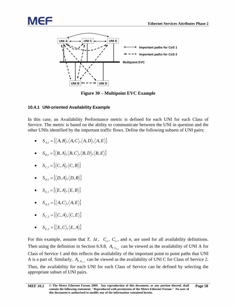
Ethernet Services Attributes Phase 2
MEF 10.2 © The Metro Ethernet Forum 2009. Any reproduction of this document, or any portion thereof, shall contain the following statement: "Reproduced with permission of the Metro Ethernet Forum." No user of this document is authorized to modify any of the information contained herein.
Page 58
UNI A UNI C UNI E
UNI B UNI D
Important paths for CoS 1
Important paths for CoS 2
Multipoint EVC
Figure 30 – Multipoint EVC Example
10.4.1 UNI-oriented Availability Example
In this case, an Availability Performance metric is defined for each UNI for each Class of Service. The metric is based on the ability to communicate between the UNI in question and the other UNIs identified by the important traffic flows. Define the following subsets of UNI pairs:
• { }EADACABAS A ,,,,,,,1, =
• { }EBDBCBABSB ,,,,,,,1, =
• { }BCACSC ,,,1, =
• { }BDADSD ,,,1, =
• { }BEAESE ,,,1, =
• { }EACASA ,,,2, =
• { }ECACSC ,,,2, =
• { }AECESE ,,,2, =
For this example, assume that T, t∆ , uC , aC , and n, are used for all availability definitions. Then using the definition in Section 6.9.8,
1,, ASTA can be viewed as the availability of UNI A for Class of Service 1 and this reflects the availability of the important point to point paths that UNI A is a part of. Similarly,
2,, CSTA can be viewed as the availability of UNI C for Class of Service 2. Thus, the availability for each UNI for each Class of Service can be defined by selecting the appropriate subset of UNI pairs.

Ethernet Services Attributes Phase 2
MEF 10.2 © The Metro Ethernet Forum 2009. Any reproduction of this document, or any portion thereof, shall contain the following statement: "Reproduced with permission of the Metro Ethernet Forum." No user of this document is authorized to modify any of the information contained herein.
Page 59
10.4.2 EVC-oriented Availability Example
In this case an Availability Performance metric is defined for each Class of Service supported by the EVC. Define the following subsets of UNI pairs:
• { }EBDBCBEADACABAS ,,,,,,,,,,,,,1 =
• { }ECEACAS ,,,,,2 =
For this example, assume that T, t∆ , uC , aC , and n, are used for both availability definitions. Then using the definition in Section 6.9.8,
1,STA can be viewed as the availability of Class of Service 1 on the EVC and
2,STA can be viewed as the availability of Class of Service 2 on the EVC.