TECHNICAL SPECIFICATION FOR AUTOMATIC … · L1-CHE-SPE-150 Approving Manager: ... 10.2 Earthing...
20
PRINTOUT MAY NOT BE UP-TO-DATE; REFER TO METRO INTRANET FOR THE LATEST VERSION Electrical Networks Specification Engineering MESP 041000-01 TECHNICAL SPECIFICATION FOR AUTOMATIC CONTROL AND INDICATED FIXED MOUNTED TRACKSIDE SWITCHGEAR FOR ESSENTIAL SERVICES PURPOSES Version: 1 Issued: July 2016 Approved By: Andrew Russack Head Of Engineering - Electrical
-
Upload
hoangduong -
Category
Documents
-
view
222 -
download
6
Transcript of TECHNICAL SPECIFICATION FOR AUTOMATIC … · L1-CHE-SPE-150 Approving Manager: ... 10.2 Earthing...
PRINTOUT MAY NOT BE UP-TO-DATE; REFER TO METRO INTRANET FOR THE LATEST VERSION
Electrical Networks Specification
Engineering
MESP 041000-01
TECHNICAL SPECIFICATION FOR AUTOMATIC CONTROL AND INDICATED
FIXED MOUNTED TRACKSIDE SWITCHGEAR FOR ESSENTIAL SERVICES PURPOSES
Version: 1
Issued: July 2016
Approved By:
Andrew Russack
Head Of Engineering - Electrical
TECHNICAL SPECIFICATION FOR AUTOMATIC CONTROL AND INDICATED FIXED MOUNTED TRACKSIDE SWITCHGEAR FOR
ESSENTIAL SERVICES PURPOSES
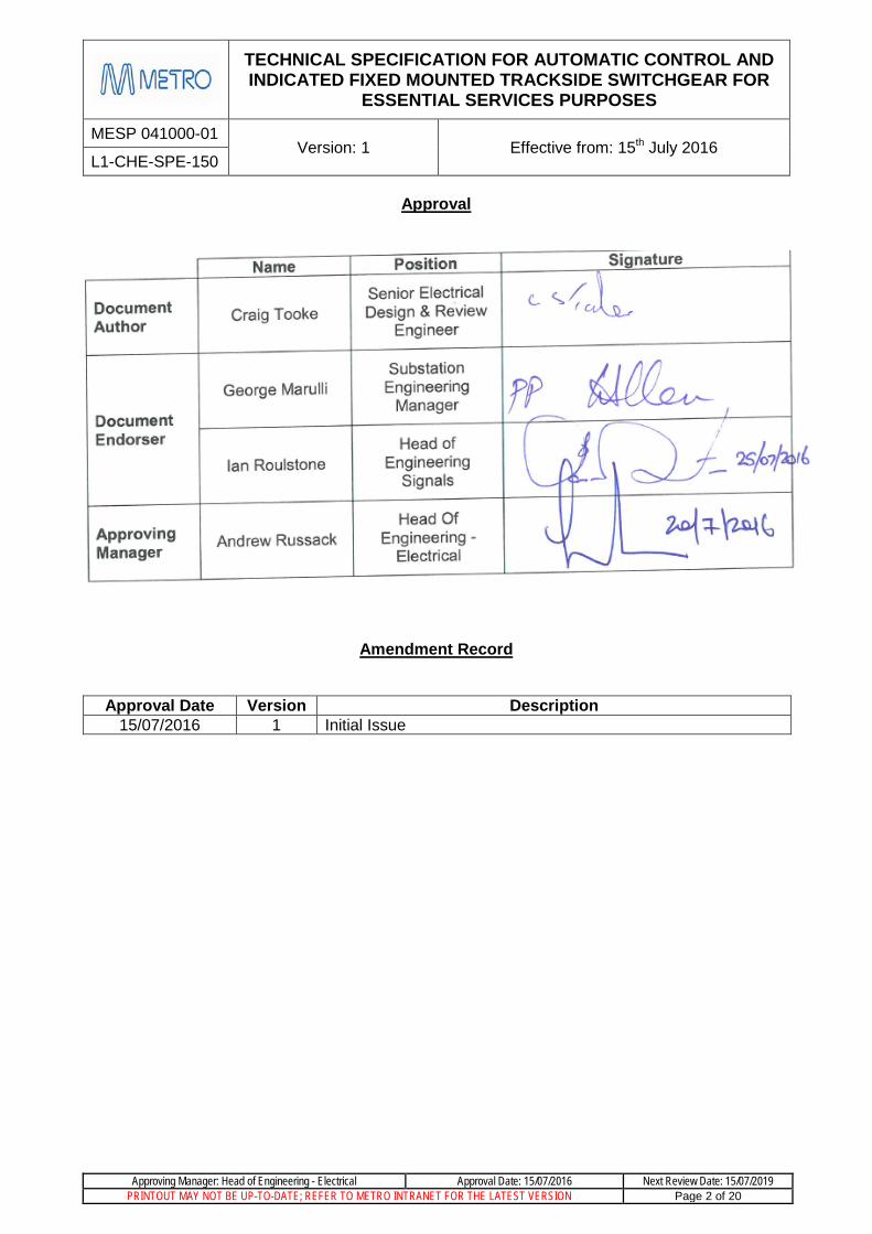
MESP 041000-01 Version: 1 Effective from: 15th July 2016
L1-CHE-SPE-150
Approving Manager: Head of Engineering - Electrical Approval Date: 15/07/2016 Next Review Date: 15/07/2019 PRINTOUT MAY NOT BE UP-TO-DATE; REFER TO METRO INTRANET FOR THE LATEST VERSION Page 2 of 20
Approval
Amendment Record
Approval Date Version Description
15/07/2016 1 Initial Issue

TECHNICAL SPECIFICATION FOR AUTOMATIC CONTROL AND INDICATED FIXED MOUNTED TRACKSIDE SWITCHGEAR FOR
ESSENTIAL SERVICES PURPOSES
MESP 041000-01 Version: 1 Effective from: 15th July 2016
L1-CHE-SPE-150
Approving Manager: Head of Engineering - Electrical Approval Date: 15/07/2016 Next Review Date: 15/07/2019 PRINTOUT MAY NOT BE UP-TO-DATE; REFER TO METRO INTRANET FOR THE LATEST VERSION Page 3 of 20
Table of Contents Purpose .............................................................................................................................. 5 1. Scope ................................................................................................................................. 5 2. Abbreviation ...................................................................................................................... 5 3. Definitions .......................................................................................................................... 5 4. References & Legislations ................................................................................................ 5 5. Application ......................................................................................................................... 7 6. Configuration ..................................................................................................................... 7 7. Service and Climatic Conditions ...................................................................................... 7 8. HV Switchgear Requirements ........................................................................................... 7 9.
Equipment Requirements .............................................................................................. 10 10. Circuit Breaker ................................................................................................................... 10 10.1
Earthing Switch .................................................................................................................. 10 10.2
Busbar................................................................................................................................ 11 10.3
Power Cable Termination .................................................................................................. 11 10.4
Phase Test and Line Alive Functional Block ..................................................................... 11 10.5
Control and Protection Functional Block ........................................................................... 11 10.6
Interlocking Requirements.............................................................................................. 13 11. Wiring ............................................................................................................................... 13 12. Accessories ..................................................................................................................... 13 13.
Labelling ............................................................................................................................ 13 13.1
Prohibited Materials ........................................................................................................... 14 13.2
Arc Venting ...................................................................................................................... 14 14. Testing ............................................................................................................................. 14 15.
Type Test ........................................................................................................................... 14 15.1
Routine Tests ..................................................................................................................... 14 15.2
Spares .............................................................................................................................. 14 16. Documentation and Support ........................................................................................... 15 17.
Documentation Requirements ........................................................................................... 15 17.1
Drawing Format ................................................................................................................. 15 17.2
Technical Maintenance Plan ............................................................................................. 15 17.3
Maintenance Manual ......................................................................................................... 15 17.4
Installation Instructions Manual ......................................................................................... 16 17.5
Operating Instructions Manual ........................................................................................... 16 17.6
Training .............................................................................................................................. 16 17.7
Tools & Equipment ............................................................................................................ 16 17.8
Design Management Requirements ............................................................................... 17 18.
TECHNICAL SPECIFICATION FOR AUTOMATIC CONTROL AND INDICATED FIXED MOUNTED TRACKSIDE SWITCHGEAR FOR
ESSENTIAL SERVICES PURPOSES
MESP 041000-01 Version: 1 Effective from: 15th July 2016
L1-CHE-SPE-150
Approving Manager: Head of Engineering - Electrical Approval Date: 15/07/2016 Next Review Date: 15/07/2019 PRINTOUT MAY NOT BE UP-TO-DATE; REFER TO METRO INTRANET FOR THE LATEST VERSION Page 4 of 20
Tender Submission ............................................................................................................ 17 18.1
Contract Documentation .................................................................................................... 17 18.2
Pre-Delivery Documentation .............................................................................................. 17 18.3
Information to be Supplied by Tenderers ...................................................................... 18 19.

TECHNICAL SPECIFICATION FOR AUTOMATIC CONTROL AND INDICATED FIXED MOUNTED TRACKSIDE SWITCHGEAR FOR
ESSENTIAL SERVICES PURPOSES
MESP 041000-01 Version: 1 Effective from: 15th July 2016
L1-CHE-SPE-150
Approving Manager: Head of Engineering - Electrical Approval Date: 15/07/2016 Next Review Date: 15/07/2019 PRINTOUT MAY NOT BE UP-TO-DATE; REFER TO METRO INTRANET FOR THE LATEST VERSION Page 5 of 20
1. Purpose This document is the MTM technical specification for automatic and fixed mounted switchgear, remotely controlled and indicated for use at trackside and other locations for switching and protection of the Railway Essential Service Power Reticulation System.
2. Scope The 3.3 kV reticulation load points including signal equipment rooms, trackside signal supply locations and stations.
The scope of supply shall include design, manufacture, assembly and testing of the equipment.
This specification is to be read in conjunction with the supplied Scope of Works document, which details exact quantities and any other special requirements.
This specification does not apply to the switchgear inside the substation which will is specified in L1-CHE-SPE-015.
3. Abbreviation ACCB - Alternating Current Circuit Breaker
ESS - Essential Services System
MTM - Metro Trains Melbourne
RTU - Remote Terminal Unit
SCADA - Supervisory, Control and Data Acquisition
4. Definitions For the purpose of this specification, the terms, definitions and abbreviated terms in AS 1852.441 apply.
Reference to all standards shall be read as a reference to the latest edition of that standard and amendments available at the time of tendering.
All materials and components shall comply with the requirements of the relevant Australian Standards, or where these do not exist, with the International Electro technical Commission (IEC) Standards.
5. References & Legislations
MTM Standards / Documents
L1-CHE-STD-015 Electrical Networks Principles & Performance
L1-CHE-STD-154 3.3kV Essential Services System
L4-CHE-INF-002 Standard Product List
IPGOR-01 PTC Train Electrical Rules (High Voltage Rules)
TECHNICAL SPECIFICATION FOR AUTOMATIC CONTROL AND INDICATED FIXED MOUNTED TRACKSIDE SWITCHGEAR FOR
ESSENTIAL SERVICES PURPOSES
MESP 041000-01 Version: 1 Effective from: 15th July 2016
L1-CHE-SPE-150
Approving Manager: Head of Engineering - Electrical Approval Date: 15/07/2016 Next Review Date: 15/07/2019 PRINTOUT MAY NOT BE UP-TO-DATE; REFER TO METRO INTRANET FOR THE LATEST VERSION Page 6 of 20
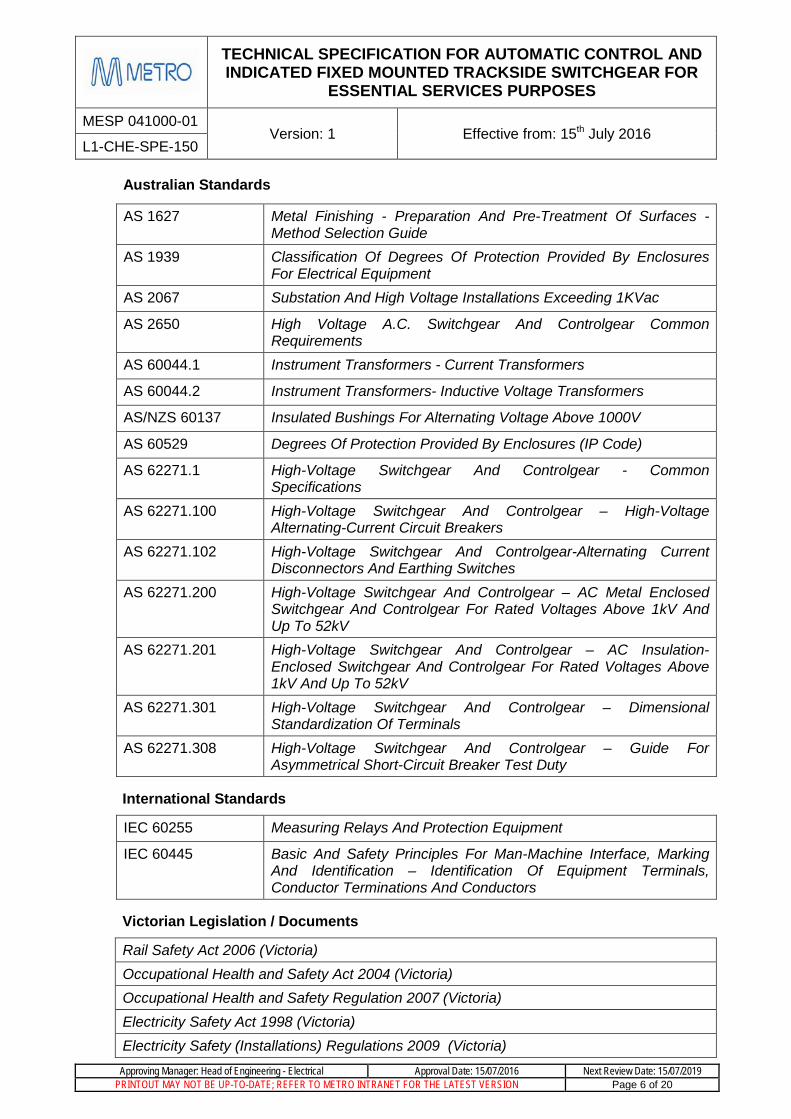
Australian Standards
AS 1627 Metal Finishing - Preparation And Pre-Treatment Of Surfaces - Method Selection Guide
AS 1939 Classification Of Degrees Of Protection Provided By Enclosures For Electrical Equipment
AS 2067 Substation And High Voltage Installations Exceeding 1KVac
AS 2650 High Voltage A.C. Switchgear And Controlgear Common Requirements
AS 60044.1 Instrument Transformers - Current Transformers
AS 60044.2 Instrument Transformers- Inductive Voltage Transformers
AS/NZS 60137 Insulated Bushings For Alternating Voltage Above 1000V
AS 60529 Degrees Of Protection Provided By Enclosures (IP Code)
AS 62271.1 High-Voltage Switchgear And Controlgear - Common Specifications
AS 62271.100 High-Voltage Switchgear And Controlgear – High-Voltage Alternating-Current Circuit Breakers
AS 62271.102 High-Voltage Switchgear And Controlgear-Alternating Current Disconnectors And Earthing Switches
AS 62271.200 High-Voltage Switchgear And Controlgear – AC Metal Enclosed Switchgear And Controlgear For Rated Voltages Above 1kV And Up To 52kV
AS 62271.201 High-Voltage Switchgear And Controlgear – AC Insulation-Enclosed Switchgear And Controlgear For Rated Voltages Above 1kV And Up To 52kV
AS 62271.301 High-Voltage Switchgear And Controlgear – Dimensional Standardization Of Terminals
AS 62271.308 High-Voltage Switchgear And Controlgear – Guide For Asymmetrical Short-Circuit Breaker Test Duty
International Standards
IEC 60255 Measuring Relays And Protection Equipment
IEC 60445 Basic And Safety Principles For Man-Machine Interface, Marking And Identification – Identification Of Equipment Terminals, Conductor Terminations And Conductors
Victorian Legislation / Documents
Rail Safety Act 2006 (Victoria) Occupational Health and Safety Act 2004 (Victoria) Occupational Health and Safety Regulation 2007 (Victoria) Electricity Safety Act 1998 (Victoria) Electricity Safety (Installations) Regulations 2009 (Victoria)

TECHNICAL SPECIFICATION FOR AUTOMATIC CONTROL AND INDICATED FIXED MOUNTED TRACKSIDE SWITCHGEAR FOR
ESSENTIAL SERVICES PURPOSES
MESP 041000-01 Version: 1 Effective from: 15th July 2016
L1-CHE-SPE-150
Approving Manager: Head of Engineering - Electrical Approval Date: 15/07/2016 Next Review Date: 15/07/2019 PRINTOUT MAY NOT BE UP-TO-DATE; REFER TO METRO INTRANET FOR THE LATEST VERSION Page 7 of 20
6. Application The MTM Substations provide a 3.3 kV three phase Essential Services Supply which is reticulated to trackside signal supply locations, communication equipment rooms, signal equipment rooms and railway stations as outlined in L1-CHE-SPE-154. The fixed switchgear will be used at these supply locations.
7. Configuration The configuration of an ESS supply point consists of:
1. A ring main ACCB switchboard typically comprising of an incoming and outgoing feeder ACCB and a local supply ACCB.
2. A step down 3.3kV/110V single phase or 3.3kV/400V three phase transformer and associated LV switchboard.
3. A dual conversion 110V or 230V UPS and RTU assembly.
This specification covers item 1 only.
The switchboard panels will be housed as follows;
• For trackside signalling supply locations the switchgear will be placed into a standard stainless steel double door cubicle, drawing STD_G0100.
• For indoor installations such as communication equipment rooms and signal equipment rooms the switchgear will be installed in a standard power equipment room.
Cables shall enter the enclosure from below.
The switchboard panels may be required to be installed on a raised metallic plinth for easy cable entry into the Power Cable Termination Compartment. The height of the plinth will be dependent on site conditions and will be specified in the scope of works document.
8. Service and Climatic Conditions Each panel shall have an earthing bar and provision shall be made to connect each panel on the switchboard to this bar. The linked earthing bar of the switchboard shall be directly connected to the location box earthing system.
The service conditions as stated in AS2067, AS2650 and AS62271.1 shall apply, except that the ambient temperature shall be taken as 50°C.
Inside the stainless steel enclosure box is a compartment separated by means by means of a metal barrier for the low voltage step down transformer and low voltage switchboard.
9. HV Switchgear Requirements The switchboard configurations shall normally consist of:
• A minimum of one incoming and one outgoing feeder ACCB
• A minimum of one load ACCB
All three phases of this 3.3 kV ESS shall be fed through the incoming and outgoing feeder ACCB’s, with only two phases connected to 3.3kV/110V single transformers and three phases to the 3.3kV/400V transformers. No loads shall be connected phase to neutral.

TECHNICAL SPECIFICATION FOR AUTOMATIC CONTROL AND INDICATED FIXED MOUNTED TRACKSIDE SWITCHGEAR FOR
ESSENTIAL SERVICES PURPOSES
MESP 041000-01 Version: 1 Effective from: 15th July 2016
L1-CHE-SPE-150
Approving Manager: Head of Engineering - Electrical Approval Date: 15/07/2016 Next Review Date: 15/07/2019 PRINTOUT MAY NOT BE UP-TO-DATE; REFER TO METRO INTRANET FOR THE LATEST VERSION Page 8 of 20
The connections to each location will be nominated to ensure near equal loading across the three phases.
The feeder ACCB shall include a cable fault detector to sense a phase to earth fault, and indicate this back to Electrol.
The switchgear shall meet the requirements detailed in Table 1.
Table 1 – Switchgear Parameters Description Requirement Value Unit
General
Number of Phases Equal to 3
Rated Nominal Voltage (Ur) Greater than or equal to 12 kV
Rated Frequency (Fr) Equal to 50 Hz
Lightning Impulse Withstand Voltage Greater than or equal to 95 kV peak
1-minute Power Frequency Withstand Voltage
Greater than or equal to 28 kV rms
Rated Normal Current of Busbar (Ir) Greater than or equal to 400 A rms
Rated Short-time Withstand Current of Circuit Breaker and Bus Riser (𝐼𝐼k)
Greater than or equal to 20 kA rms
for 3s
Rated Normal Current of Circuit Breaker , Switch Disconnector and Bus Riser (Ir)
Greater than or equal to 400 A rms
Loss of Service Continuity Classification
Switchgear and Control gear of a functional unit are accessible while the busbar compartment is energised.
LSC2B
Partition Class Metallic partitions between live parts of the main circuit.
PM
Internal Arc Classification Restricted to authorised personnel only.
Shall be accessible from the front, lateral and rear of the functional unit.
AFLR
Control Voltage Equal to 24, 48, 110 or 125
(specified at time of ordering)
V DC

TECHNICAL SPECIFICATION FOR AUTOMATIC CONTROL AND INDICATED FIXED MOUNTED TRACKSIDE SWITCHGEAR FOR
ESSENTIAL SERVICES PURPOSES
MESP 041000-01 Version: 1 Effective from: 15th July 2016
L1-CHE-SPE-150
Approving Manager: Head of Engineering - Electrical Approval Date: 15/07/2016 Next Review Date: 15/07/2019 PRINTOUT MAY NOT BE UP-TO-DATE; REFER TO METRO INTRANET FOR THE LATEST VERSION Page 9 of 20
Description Requirement Value Unit Circuit Breaker Rated Short-Circuit Breaking Current of Circuit Breaker (I𝑠𝑠𝑠𝑠)
Greater than or equal 20 kA rms
Rated Short-Circuit Making Current of Circuit Breaker, Switch Disconnector and of Earthing Switch
Greater than or equal to 50 kA peak
Rated Operating Sequence of Circuit Breaker (refer AS 62271-100-2008)
O – 0.3S –CO -15 s – CO
Maximum Opening Time of Circuit Breaker (Fault detection to arc extinguishing)
Less than or equal to 100 ms
No load Mechanical Endurance of Circuit Breakers
Greater than or equal to
(M2 Class IEC 62271-100-Clause 3.4.117)
10,000 Operations
Electrical Endurance of Circuit Breakers
Does not require maintenance of the interrupting parts of the main circuit during its expected operating life and only minimal maintenance on its other parts
Class E2 with
reclosing duty in
accordance with IEC
62271-100
Number of switching operations at rated short-circuit breaking current for circuit breaker
Greater than or equal to
50 Operations
Earthing Switch
No load Mechanical Endurance of Earthing Switch
Greater than or equal to 1,000 Operations
(M2 Class IEC 62271-102)
Electrical Endurance of Earthing Switches
Minimal maintenance required on all moving part of the main and auxiliary circuits
Class E2 in accordance
with IEC 62271-102
Making Capacity endurance of Earthing Switch
Greater than or equal to 5 Operations
(E2 Class IEC 62271-102)
Electrical Endurance of Switch Greater than or equal to 100 Operations
(E3 Class IEC 62271-103)

TECHNICAL SPECIFICATION FOR AUTOMATIC CONTROL AND INDICATED FIXED MOUNTED TRACKSIDE SWITCHGEAR FOR
ESSENTIAL SERVICES PURPOSES
MESP 041000-01 Version: 1 Effective from: 15th July 2016
L1-CHE-SPE-150
Approving Manager: Head of Engineering - Electrical Approval Date: 15/07/2016 Next Review Date: 15/07/2019 PRINTOUT MAY NOT BE UP-TO-DATE; REFER TO METRO INTRANET FOR THE LATEST VERSION Page 10 of 20
10. Equipment Requirements
Circuit Breaker 10.1The circuit breaker shall be a fixed mounted three pole vacuum interrupter which shall meet the requirements of Table 1.
The circuit breaker shall be able to be operated electrically and manually.
The electrical closing and opening of the circuit breaker shall be able to be performed locally from the front of the functional unit, and remotely from the SCADA system.
The manual closing and opening of the circuit breaker shall be able to be performed with the operating lever provided with the switchgear assembly.
A built-in padlocking facility with a minimum 6mm shank shall be provided for the manual operation of the circuit breaker to prevent insertion of the circuit breaker operating lever when the earthing switch is closed.
A mechanical indication of the status of the circuit breaker shall be provided on the front of the unit.
The circuit breaker shall be fitted with a non-resettable mechanical operations counter.
There shall be a minimum of 3 normally open and 3 normally closed voltage free auxiliary contacts provided for control and indication purposes in addition to those required for operation and local indication of the circuit breaker.
A mushroom style pushbutton shall be provided on front of the circuit breaker to open the circuit breaker locally as may be required under emergency conditions. It shall be situated so as to discourage accidental operation.
Earthing Switch 10.2The earthing switch shall be a manually operated, two position fault making switch. An anti reflex lever operated mechanism which is independent of the operator action shall be provided to manually open or close the earth switch.
The earthing switch shall be interlocked as described in section 11 such that it shall not be possible to close an earthing switch onto a live cable.
The two position switch shall connect from the circuit breaker to the outgoing or incoming feeder in one position, and in the second position shall connect the outgoing or incoming feeder to earth.
The earthing switch shall be provided with a descriptive indication on the front panel.
A built-in padlocking facility with a minimum 6mm shank shall be provided for the earthing switch to prevent insertion of the earth switch operating lever.
The contacts of the earthing switch shall be clearly visible from the front of the circuit breaker.
If internal illumination is required for the contacts to be visible, it shall be provided by a double insulated non-metallic light fitted to the circuit breaker, powered by the control supply.
The light shall be able to be replaced from outside the cubicle without requiring de-energisation.

TECHNICAL SPECIFICATION FOR AUTOMATIC CONTROL AND INDICATED FIXED MOUNTED TRACKSIDE SWITCHGEAR FOR
ESSENTIAL SERVICES PURPOSES
MESP 041000-01 Version: 1 Effective from: 15th July 2016
L1-CHE-SPE-150
Approving Manager: Head of Engineering - Electrical Approval Date: 15/07/2016 Next Review Date: 15/07/2019 PRINTOUT MAY NOT BE UP-TO-DATE; REFER TO METRO INTRANET FOR THE LATEST VERSION Page 11 of 20
The light shall be switched by means of a spring-return, push-button switch, ensuring the earthing switch is only illuminated whilst the push-button switch is being depressed.
Busbar 10.3A single Busbar system shall be provided. It shall be modular in design to connect all ACCB’s.
The Busbar shall be encased with shielded solid insulation, be designed to be essentially maintenance free, not be able to be accessed and not be exposed to free air.
Power Cable Termination 10.4The power cable terminals shall be in a separate metal enclosed compartment.
The compartment shall be suitable for the power cables to enter from either above or below the functional unit.
The power cable terminals shall be suitable for the connection of an appropriately terminated insulated cable. The cross-section area of the cable cores shall be between 16 and 35mm².
Appropriate brackets and clamps shall be provided to adequately support the cables in the compartment so that the weight of the conductor is not taken by the terminals.
Appropriate brackets shall be provided to securely position and fix a current transformer if required, within the cable termination compartment.
The middle termination shall be provided with a shielded insulated cover.
A ‘DANGER HIGH VOLTAGE’ sign shall be placed on the Power Cable Termination door / panel.
Phase Test and Line Alive Functional Block 10.5Provision shall be provided for testing the power cable for phase identification without dismantling the power cable connections.
Provision shall be provided for a testing device to be connected at the front of the functional unit.
The block shall also include an LED indication to indicate if each of the phases is alive.
The line alive LED indication shall be appropriately labelled and positioned in line with a single line mimic to assist the operator to view the device being monitored.
A SCADA indication shall be provided to indicate a line alive status.
The functional block shall meet the requirements of standard IEC 62271-206.
Control and Protection Functional Block 10.6
Control Requirements 10.6.1Each switchboard shall be provided with a metallically segregated Low Voltage Control Compartment. It shall be located at the front of each switchboard panel.
The compartment shall contain all of the measurement, control, protection and auxiliary equipment necessary for the operation of the ACCB and earth switch.

TECHNICAL SPECIFICATION FOR AUTOMATIC CONTROL AND INDICATED FIXED MOUNTED TRACKSIDE SWITCHGEAR FOR
ESSENTIAL SERVICES PURPOSES
MESP 041000-01 Version: 1 Effective from: 15th July 2016
L1-CHE-SPE-150
Approving Manager: Head of Engineering - Electrical Approval Date: 15/07/2016 Next Review Date: 15/07/2019 PRINTOUT MAY NOT BE UP-TO-DATE; REFER TO METRO INTRANET FOR THE LATEST VERSION Page 12 of 20
Access to the compartment shall be by a hinged, dustproof door with a non-locking handle.
The ACCB shall be locally controlled by a control switch on the front panel of the circuit breaker fitted with a pistol grip handle. The control switch shall be positioned at an accessible height no greater than 1.6 metres from ground level. It shall have a neutral centre position, with closure of the circuit breaker when the control switch is turned to the left of centre and opening of the circuit breaker when the switch is turned to the right of centre. The control switch shall have a spring return to the centre position. The switch shall be labelled “Trip”, “Normal” and “Close” for the relative position.
Indicating Lights shall be provided on the front panel of the circuit breaker for the Open (GREEN) and Closed (RED) indications of the Circuit Breaker. These shall be energized by dedicated and electrically isolated auxiliary contacts of the Circuit Breaker.
All Indicating Lights shall be long life, high reliability type LED lights.
A single switch shall be provided to switch on and off the Indicating Lights. A push button type ‘Lamp Test Switch’ for the testing of all indicating lights on the switchgear assembly shall be provided.
The control circuit shall contain interposing relays for remote SCADA control operations. The Interposing “Open” Relay coil and “Close” Relay coil shall have a current consumption of 1-2W at the Control Voltage. The operate pulse time of the SCADA system is 1 second. Device labels ‘#216’ for Open and “#217’ for Close shall be provided.
A two position C & I Isolating Switch, with pistol grip handle and a yellow escutcheon shall be provided to isolate the control and indication function of the circuit breaker from the SCADA System. When in the isolated position, both control and indication shall be isolated from remote operation by disconnection of the commons. The switch positions shall be labelled “Isolated” and “Normal”.
The opening of the circuit breaker under a fault condition, remotely, or via a pushbutton on the panel shall not require another open command to be issued before electrically reclosing the circuit breaker.
The control of the circuit breaker shall be achieved as simply as possible via relay logic, and preferably without the use of programmable logic controllers.
The layout of switches, lights and buttons on the control panel shall be approved by MTM prior to commencement of manufacture.
Protection System Requirements 10.6.2The Functional Unit shall be provided with an overcurrent protection system.
A protection relay and associated current transformers shall be provided. The relay type shall be specified by MTM Engineering and advised in procurement documents.
All relays shall be programmed for Distributed Network Protocol (DNP3).
The Protection Relay shall be securely mounted on the low voltage control compartment door and positioned no greater than 1.6 meters from ground level.

TECHNICAL SPECIFICATION FOR AUTOMATIC CONTROL AND INDICATED FIXED MOUNTED TRACKSIDE SWITCHGEAR FOR
ESSENTIAL SERVICES PURPOSES
MESP 041000-01 Version: 1 Effective from: 15th July 2016
L1-CHE-SPE-150
Approving Manager: Head of Engineering - Electrical Approval Date: 15/07/2016 Next Review Date: 15/07/2019 PRINTOUT MAY NOT BE UP-TO-DATE; REFER TO METRO INTRANET FOR THE LATEST VERSION Page 13 of 20
The Protection Relay shall be provided with isolating Test Links mounted on the door. The preferred Test Terminals are Weidmuller type WTL6/1/STB – part no. 1016900000 or equivalent. The Test Links shall be connected to each of the Current Transformer connections to the Relay, and to the main Tripping Contacts of the Relay.
11. Interlocking Requirements The ACCB shall have identical interlocking requirements between the main switch and earthing switch.
The earthing switch shall be mechanically interlocked such that the earth switch cannot be closed unless the line side is de-energised.
Mechanical interlocking shall allow a padlock to be attached to lock the earth switch in the earth position.
The compartment housing the power cable terminals shall have interlock-controlled access. It shall only be accessible when the line earthing switch is closed.
The ACCB shall be prevented from closing if the cable termination door is open.
12. Wiring The control and auxiliary wiring terminals for connection to external circuits shall be located in a suitable position inside the control compartment.
The terminals for the external SCADA cables shall be disconnect test terminals with test sockets. This is to facilitate the isolation of the SCADA cables for testing and fault finding purposes of the input and output Essential Services. All terminals shall be screw type terminals, such that set screws shall be used to secure wiring in terminals.
All conductors used for control voltage wiring shall be stranded copper and have a cross sectional area of not less than 1.5 mm² and shall be insulated to 1 kV.
A system of permanent labelling for identification of all cables shall be used. The label shall appear on each end of each wire. The label shall be securely attached to the cables and be easily readable.
All wiring shall be arranged as simple as possible so that the course of each conductor may be readily traced.
All SCADA related terminals shall be positioned together.
A terminal layout drawing shall be provided by the manufacturer.
13. Accessories
Labelling 13.1All switching devices, control switches, components and indicators shall be labelled and have appropriate warning signs.
The external labels on each functional unit shall be of the Traffolyte type and shall be fastened by screws or equivalent.
TECHNICAL SPECIFICATION FOR AUTOMATIC CONTROL AND INDICATED FIXED MOUNTED TRACKSIDE SWITCHGEAR FOR
ESSENTIAL SERVICES PURPOSES
MESP 041000-01 Version: 1 Effective from: 15th July 2016
L1-CHE-SPE-150
Approving Manager: Head of Engineering - Electrical Approval Date: 15/07/2016 Next Review Date: 15/07/2019 PRINTOUT MAY NOT BE UP-TO-DATE; REFER TO METRO INTRANET FOR THE LATEST VERSION Page 14 of 20
All control wiring shall have sleeved cable markers.
The switchboard shall have a mimic line diagram illustrating the switchboard connectivity. It shall be made of Traffolyte.
Prohibited Materials 13.2There shall be no asbestos or materials containing asbestos in the Switchgear and Control gear. A statement certifying that the product is free of asbestos containing materials must be completed and signed, and delivered to MTM prior to dispatch.
14. Arc Venting The tenderer shall indicate if arc venting is required with the equipment offered, to meet the conditions of the equipment type tests, under the voltage and current fault levels specified.
15. Testing
Type Test 15.1The Switchgear shall have Type Test Certificates complying with AS 62271. The Certificates shall include oscillograms and drawings of the test circuit. Copies of these Certificates shall be supplied with the tender documentation.
Routine Tests 15.2The Switchgear and Control gear shall be subjected to Routine Tests at the Manufacturer’s Workshop complying with AS 62271.
MTM reserves the right to appoint a representative to witness these Tests. Seven working days’ notification shall be given to MTM of intention to carry out factory testing. The results of all Routine Tests shall be recorded on test certificates. The test certificates shall clearly show the performance of the equipment and shall be accompanied by tables showing the actually measured values and all calculations.
The test certificates shall be forwarded to MTM and the results approved by MTM prior to delivery.
The specific requirements of an inspection and test plan for each site will be specified in the scope of works.
16. Spares The Supplier shall provide a list of spares which it considers necessary to ensure prompt repair of the equipment, including relays, switches and other items.

TECHNICAL SPECIFICATION FOR AUTOMATIC CONTROL AND INDICATED FIXED MOUNTED TRACKSIDE SWITCHGEAR FOR
ESSENTIAL SERVICES PURPOSES
MESP 041000-01 Version: 1 Effective from: 15th July 2016
L1-CHE-SPE-150
Approving Manager: Head of Engineering - Electrical Approval Date: 15/07/2016 Next Review Date: 15/07/2019 PRINTOUT MAY NOT BE UP-TO-DATE; REFER TO METRO INTRANET FOR THE LATEST VERSION Page 15 of 20
17. Documentation and Support The Supplier must supply all materials, special tools and documents for the Switchgear and Control gear. The documents shall contain all necessary information and instructions required for operation and maintenance of all items.
Documentation Requirements 17.1All documentation shall be provided in English.
One electronic and eight paper copies of the each final document shall be provided and the content shall be identical in each copy.
Every page of the documentation shall be clearly identified in relation to the document to which it belongs and the version of that document. All pages of multi-page documents shall be uniquely numbered. It shall be possible to readily determine if all pages of a document are present.
Manuals shall be A4 size and shall be bound in durable covers or in 4-D ring binders.
Drawing Format 17.2All drawings must comply with the PTV Infrastructure Drafting Standard
Files shall be provided in Microstation format on a compact disk (CD).
Technical Maintenance Plan 17.3A Technical Maintenance Plan which establishes the maintenance policy for the Switchgear as recommended by the Supplier shall be provided. This shall detail the preventative servicing schedules and maintenance intervals for all components. The servicing schedules shall reference appropriate detailed instructions in the maintenance manual.
A condition based maintenance interval shall be provided to optimise the balance between maintenance work and risk of failure.
The Technical Maintenance Plan shall contain a list of any recommended spare parts, detailing price, supplier and procurement lead-times.
The Technical Maintenance Plan shall detail safe disposal procedures applicable for when the Assembly is no longer serviceable (recycling, hazardous waste etc.).
Maintenance Manual 17.4The Maintenance Manual shall detail:
a) The theory of operation of the equipment.
b) All servicing activities.
c) Overhaul instructions.
d) Adjustment procedures.
e) The changing of components for repairs.
f) Fault-finding procedures.
g) The spares support schedule.

TECHNICAL SPECIFICATION FOR AUTOMATIC CONTROL AND INDICATED FIXED MOUNTED TRACKSIDE SWITCHGEAR FOR
ESSENTIAL SERVICES PURPOSES
MESP 041000-01 Version: 1 Effective from: 15th July 2016
L1-CHE-SPE-150
Approving Manager: Head of Engineering - Electrical Approval Date: 15/07/2016 Next Review Date: 15/07/2019 PRINTOUT MAY NOT BE UP-TO-DATE; REFER TO METRO INTRANET FOR THE LATEST VERSION Page 16 of 20
The Maintenance Manual shall also include a complete set of as-built drawings and a comprehensive parts list for the Assembly.
Installation Instructions Manual 17.5The installation Instructions Manual shall enable the Switchgear to be properly installed, tested and commissioned. This shall include all necessary drawings, and information regarding the storage, handling, loading and off-loading instructions.
Operating Instructions Manual 17.6The Operating Instructions Manual shall clearly describe the required procedures for physically operating all of the components of the Switchgear.
The operating procedures shall be consistent with the PTC Train Infrastructure Electrical Safety Rules (High Voltage Rules) (IPGOR-01).
Training 17.7The manufacturer shall provide full training for a person nominated by MTM. The training shall include instruction on the operation and maintenance of the switchgear, to a sufficient level to in turn instruct MTM staff and its agents.
The manufacturer shall prepare a suitable operating instruction for the switchgear, in the required MTM format, for the objective of training of MTM staff and its agents.
Tools & Equipment 17.8A complete set of operating tools and any other equipment necessary to operate and maintain the Switchgear and Control gear shall be provided. This shall include any special devices required to test the Switchgear and Control gear. Storage facilities for the tools and equipment shall also be provided.
The software and a portable computer interface for loading and downloading of Protection Relay settings and the latest fault current data to a laptop portable computer shall be provided. This shall include all peripheral interfacing equipment and connection cables necessary to connect and communicate with the system.
Any special lifting and installation equipment shall be supplied with the Switchgear.
TECHNICAL SPECIFICATION FOR AUTOMATIC CONTROL AND INDICATED FIXED MOUNTED TRACKSIDE SWITCHGEAR FOR
ESSENTIAL SERVICES PURPOSES
MESP 041000-01 Version: 1 Effective from: 15th July 2016
L1-CHE-SPE-150
Approving Manager: Head of Engineering - Electrical Approval Date: 15/07/2016 Next Review Date: 15/07/2019 PRINTOUT MAY NOT BE UP-TO-DATE; REFER TO METRO INTRANET FOR THE LATEST VERSION Page 17 of 20
18. Design Management Requirements This section describes the documentation which should be provided as a minimum at each stage of the procurement process. The documentation shall comply with the specifications above.
Tender Submission 18.1
The following documents shall be provided as part of the tender submission:
• Pamphlets detailing the operating and interlocking principles of the Switchgear and Control gear.
• A General Arrangement drawing of the Switchgear which clearly shows:
o The overall dimensions of the Switchgear and each Module.
o Details of the proposed cable terminals and cable entry requirements
o Typical Control Schematics
• Type Test Certificates
• The Technical Data Schedule in Section 21 filled in.
• A list of recommended spare parts.
Contract Documentation 18.2One set of PDF copies of the drawings and documentation detailed in Section 19, including any other information considered necessary for completeness shall be provided for review and approval by MTM four weeks after the Contact Award Date. No manufacture shall commence until the drawings have been approved. An allowance of seven working days should be made by the Supplier for the review and approval of submitted documents.
A draft Installation Instructions Manual shall also be included.
Pre-Delivery Documentation 18.3Prior to delivery, the Supplier shall provide the paper and electronic copies of the Manuals, Drawings and Routine Test Certificates.

TECHNICAL SPECIFICATION FOR AUTOMATIC CONTROL AND INDICATED FIXED MOUNTED TRACKSIDE SWITCHGEAR FOR
ESSENTIAL SERVICES PURPOSES
MESP 041000-01 Version: 1 Effective from: 15th July 2016
L1-CHE-SPE-150
Approving Manager: Head of Engineering - Electrical Approval Date: 15/07/2016 Next Review Date: 15/07/2019 PRINTOUT MAY NOT BE UP-TO-DATE; REFER TO METRO INTRANET FOR THE LATEST VERSION Page 18 of 20
19. Information to be Supplied by Tenderers The Tenderers shall supply all of the information requested, and fill in the Information and Guaranteed Performance Schedule below for the Switchgear and Control gear offered. Where the equipment offered complies with other national or international standards it is the responsibility of the Tenderer to prove the equivalence of these standards.
Manufacturer
1 Manufacturer’s Name
2 Manufacturer’s Address
General
3 Manufacturer’s Switchgear Type
4 Model Type
5 Busbar Insulation System
6 Enclosure Type and Material
7 Partitioning between Switching Elements Type
8 IP rating
9 Overall dimensions (l x h x d mm)
10 Weight, Circuit Breaker Functional Unit kg
11 Weight, Bus-Tie Switch Disconnector Functional Unit kg
12 Lifting Facilities
General Electrical Specifications
14 Nominal Voltage kV
15 Rated Frequency Hz
16 Rated Busbar, circuit breaker and disconnect switch Normal Current A
17 Rated Short-circuit Level MVA

TECHNICAL SPECIFICATION FOR AUTOMATIC CONTROL AND INDICATED FIXED MOUNTED TRACKSIDE SWITCHGEAR FOR
ESSENTIAL SERVICES PURPOSES
MESP 041000-01 Version: 1 Effective from: 15th July 2016
L1-CHE-SPE-150
Approving Manager: Head of Engineering - Electrical Approval Date: 15/07/2016 Next Review Date: 15/07/2019 PRINTOUT MAY NOT BE UP-TO-DATE; REFER TO METRO INTRANET FOR THE LATEST VERSION Page 19 of 20
18 Number of Phases
19 Rated Lightning Impulse Withstand Voltage kV
20 Rated short-duration Power-frequency Withstand Voltage at what time duration
kV
Sec
21 Loss of Service Continuity Classification
22 Partition Class
23 Internal Arc Classification
Circuit Breaker
21 Manufacturer
22 Model Type
22 Interrupter Type
23 Rated Normal current A
24 Rated short circuit Breaking Current kA
25 Rated short circuit Making Current kA
26 Operating Sequence
27 Rated supply voltage of closing and opening devices V
28 Maximum Opening Time of Circuit Breaker ms
29 No Load Mechanical Endurance Of Circuit Breakers Operations
30 Electrical Endurance
31 Number of Switching Operations at Rated Short Circuit Breaking Current Operations
TECHNICAL SPECIFICATION FOR AUTOMATIC CONTROL AND INDICATED FIXED MOUNTED TRACKSIDE SWITCHGEAR FOR
ESSENTIAL SERVICES PURPOSES
MESP 041000-01 Version: 1 Effective from: 15th July 2016
L1-CHE-SPE-150
Approving Manager: Head of Engineering - Electrical Approval Date: 15/07/2016 Next Review Date: 15/07/2019 PRINTOUT MAY NOT BE UP-TO-DATE; REFER TO METRO INTRANET FOR THE LATEST VERSION Page 20 of 20
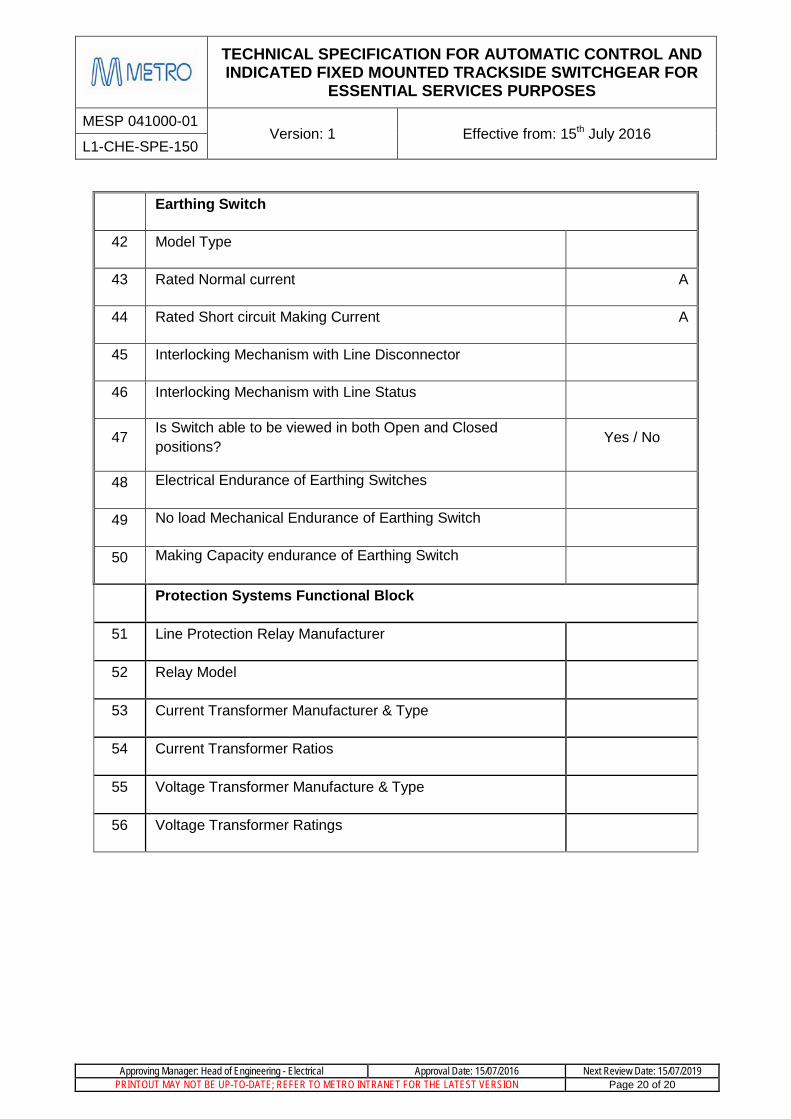
Earthing Switch
42 Model Type
43 Rated Normal current A
44 Rated Short circuit Making Current A
45 Interlocking Mechanism with Line Disconnector
46 Interlocking Mechanism with Line Status
47 Is Switch able to be viewed in both Open and Closed positions? Yes / No
48 Electrical Endurance of Earthing Switches
49 No load Mechanical Endurance of Earthing Switch
50 Making Capacity endurance of Earthing Switch
Protection Systems Functional Block
51 Line Protection Relay Manufacturer
52 Relay Model
53 Current Transformer Manufacturer & Type
54 Current Transformer Ratios
55 Voltage Transformer Manufacture & Type
56 Voltage Transformer Ratings