Technical Specification FLUXUS® G601Technical Specification FLUXUS® G601 Example for the Equipment...
28
Technical Specification FLUXUS® G601 TSFLUXUS_G601V1-5-1US_Lus, 2014-02-25 1 FLUXUS supported by handle Measurement with transducers mounted by the portable Variofix VP Measurement equipment in transport case G601 Portable Ultrasonic Flow Measurement of Gas Portable instrument for non-intrusive, quick ultrasonic flow measurement with clamp-on technology for all types of piping Features • Precise bi-directional and highly dynamic flow measure- ment with the non-intrusive clamp-on technology • High precision at fast and slow flow rates, high tem- perature and zero point stability • Portable, easy-to-use flow transmitter with 2 flow chan- nels, multiple inputs/outputs, an integrated data logger with a serial interface • Water and dust-tight (NEMA 4); resistant against oil, many liquids and dirt • Li-Ion battery provides up to 14 hours of measurement operation • Automatic loading of calibration data and transducer detection for a fast and easy set-up (less than 5 min), providing precise and long-term stable results • User-friendly design • Transducers available for a wide range of inner pipe diameters ( ) and fluid temperatures ( ) • Probe for wall thickness measurement available • Robust, water-tight (NEMA 4) transport case with com- prehensive accessories • QuickFix for fast mounting of the flow transmitter in diffi- cult conditions Applications Designed for industrial use in harsh environments, in gas processing and natural gas extraction, chemical industry and in the petroleum industry. Practical applications: • Measurement on natural gas pipelines and in natural gas storage installations • Measurement of synthesized gas and injection gas • Measurement for the gas supply industry • Supervision of permanently installed meters, service and maintenance 0.3 to 63 in -40 to +392 °F
Transcript of Technical Specification FLUXUS® G601Technical Specification FLUXUS® G601 Example for the Equipment...

Technical Specification
FLUXUS® G601
TSFLUXUS_G601V1-5-1US_Lus, 2014-02-25 1
FLUXUS supported by handle
Measurement with transducers mounted by the portable Variofix VP
Measurement equipment in transport case
G601
Portable Ultrasonic Flow Measurement of Gas
Portable instrument for non-intrusive, quick ultrasonic flow measurement with clamp-on technology for all types of piping
Features
• Precise bi-directional and highly dynamic flow measure-ment with the non-intrusive clamp-on technology
• High precision at fast and slow flow rates, high tem-perature and zero point stability
• Portable, easy-to-use flow transmitter with 2 flow chan-nels, multiple inputs/outputs, an integrated data logger with a serial interface
• Water and dust-tight (NEMA 4); resistant against oil, many liquids and dirt
• Li-Ion battery provides up to 14 hours of measurement operation
• Automatic loading of calibration data and transducer detection for a fast and easy set-up (less than 5 min), providing precise and long-term stable results
• User-friendly design
• Transducers available for a wide range of inner pipe diameters ( ) and fluid temperatures ( )
• Probe for wall thickness measurement available
• Robust, water-tight (NEMA 4) transport case with com-prehensive accessories
• QuickFix for fast mounting of the flow transmitter in diffi-cult conditions
Applications
Designed for industrial use in harsh environments, in gas processing and natural gas extraction, chemical industry and in the petroleum industry. Practical applications:
• Measurement on natural gas pipelines and in natural gas storage installations
• Measurement of synthesized gas and injection gas
• Measurement for the gas supply industry
• Supervision of permanently installed meters, service and maintenance
0.3 to 63 in-40 to +392 °F

FLUXUS® G601 Technical Specification
Table of Contents
TSFLUXUS_G601V1-5-1US_Lus, 2014-02-252
Function ........................................................................................................................................................... 3Measurement Principle ..................................................................................................................................... 3Calculation of Volumetric Flow Rate ................................................................................................................. 3Number of Sound Paths.................................................................................................................................... 4Typical Measurement Setup ............................................................................................................................. 5Standard Volumetric Flow Rate ........................................................................................................................ 5
Flow Transmitter ............................................................................................................................................. 6Technical Data .................................................................................................................................................. 6Dimensions ....................................................................................................................................................... 8Standard Scope of Supply ................................................................................................................................ 9Connection of Adapters................................................................................................................................... 10Example for the Equipment of a Transport Case ............................................................................................ 11
Transducers................................................................................................................................................... 12Transducer Selection ...................................................................................................................................... 12Transducer Order Code .................................................................................................................................. 15Technical Data ................................................................................................................................................ 16
Transducer Mounting Fixture ...................................................................................................................... 21
Coupling Materials for Transducers............................................................................................................ 23
Damping Mats (optional) .............................................................................................................................. 24
Connection Systems..................................................................................................................................... 25Transducer Cable............................................................................................................................................ 25
Clamp-on Temperature Probe (optional) .................................................................................................... 26
Wall Thickness Measurement (optional)..................................................................................................... 27
TSFLUXUS_G601V1-5-1US_Lus, 2014-02-25 3
Technical Specification FLUXUS® G601
Function
Measurement Principle
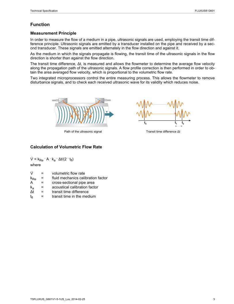
In order to measure the flow of a medium in a pipe, ultrasonic signals are used, employing the transit time dif-ference principle. Ultrasonic signals are emitted by a transducer installed on the pipe and received by a sec-ond transducer. These signals are emitted alternately in the flow direction and against it.
As the medium in which the signals propagate is flowing, the transit time of the ultrasonic signals in the flowdirection is shorter than against the flow direction.
The transit time difference, ∆t, is measured and allows the flowmeter to determine the average flow velocityalong the propagation path of the ultrasonic signals. A flow profile correction is then performed in order to ob-tain the area averaged flow velocity, which is proportional to the volumetric flow rate.
Two integrated microprocessors control the entire measuring process. This allows the flowmeter to removedisturbance signals, and to check each received ultrasonic wave for its validity which reduces noise.
Calculation of Volumetric Flow Rate
= kRe . A . ka . ∆t/(2 . tfl)
where
Path of the ultrasonic signal Transit time difference ∆t
= volumetric flow ratekRe = fluid mechanics calibration factorA = cross-sectional pipe areaka = acoustical calibration factor∆t = transit time differencetfl = transit time in the medium
V·
V·
4 TSFLUXUS_G601V1-5-1US_Lus, 2014-02-25
FLUXUS® G601 Technical Specification
Number of Sound Paths
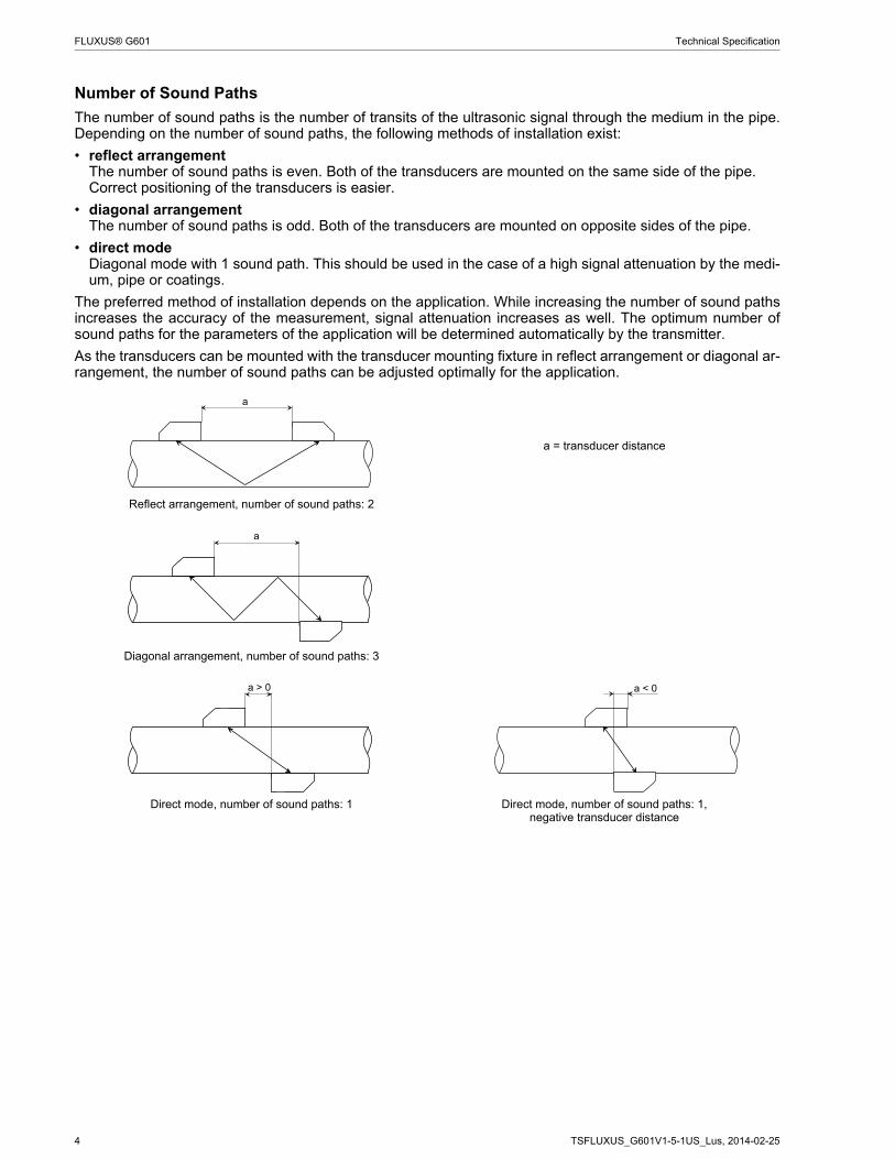
The number of sound paths is the number of transits of the ultrasonic signal through the medium in the pipe.Depending on the number of sound paths, the following methods of installation exist:
• reflect arrangementThe number of sound paths is even. Both of the transducers are mounted on the same side of the pipe. Correct positioning of the transducers is easier.
• diagonal arrangementThe number of sound paths is odd. Both of the transducers are mounted on opposite sides of the pipe.
• direct modeDiagonal mode with 1 sound path. This should be used in the case of a high signal attenuation by the medi-um, pipe or coatings.
The preferred method of installation depends on the application. While increasing the number of sound pathsincreases the accuracy of the measurement, signal attenuation increases as well. The optimum number ofsound paths for the parameters of the application will be determined automatically by the transmitter.
As the transducers can be mounted with the transducer mounting fixture in reflect arrangement or diagonal ar-rangement, the number of sound paths can be adjusted optimally for the application..
a = transducer distance
Reflect arrangement, number of sound paths: 2
Diagonal arrangement, number of sound paths: 3
Direct mode, number of sound paths: 1 Direct mode, number of sound paths: 1,negative transducer distance
a
a
a > 0 a < 0

TSFLUXUS_G601V1-5-1US_Lus, 2014-02-25 5
Technical Specification FLUXUS® G601
Typical Measurement Setup
Standard Volumetric Flow Rate
The standard volumetric flow rate can be selected as physical quantity to be measured. It will be calculated in-ternally by:
N = . p/pN . TN/T . 1/K
where
The operational pressure p and the operational temperature T of the medium will be entered directly as fixedvalues into the transmitter.
or:
If inputs are installed (optional), pressure and temperature can be measured by the customer and fed in thetransmitter.
The gas compressibility coefficient K of the gas is entered in the transmitter:
• as fixed value or
• as approximation according to e.g. AGA8 or GERG
Example of a measurement setup in reflect arrangement with connection of the inputsto an external process pressure and process temperature measurement for standard volumetric flow rate calculation
N = standard volumetric flow rate= operating volumetric flow rate
pN = standard pressure (absolute value)p = operating pressure (absolute value)TN = standard temperature in KT = operating temperature in KK = compressibility coefficient of the gas: ratio of the compressibility factors of the gas at operating
conditions and at standard conditions Z/ZN
!
" # " $ %
P T
transducers
damping mat
transmitter
RS232
outputs inputs
power supply unit/battery charging unit
temperature probee.g. external pressure sensor
V· V·
V·
V·

6 TSFLUXUS_G601V1-5-1US_Lus, 2014-02-25
FLUXUS® G601 Technical Specification
Flow Transmitter
Technical Data
FLUXUS G601design portable
measurementmeasurement principle transit time difference correlation principleflow velocity 0.03 to 115 ft/s, depending on pipe diameterrepeatability 0.15 % of reading ±0.03 ft/smedium all acoustically conductive gases,
e.g. nitrogen, air, oxygen, hydrogen, argon, helium, ethylene, propanetemperature compensation corresponding to the recommendations in ANSI/ASME MFC-5.1-2011
accuracyvolumetric flow rate ± 1 to 3 % of reading ±0.03 ft/s depending on application
± 0.5 % of reading ±0.03 ft/s with field calibrationflow transmitterpower supply 100 to 240 V/50 to 60 Hz (power supply unit),
10.5 to 15 V DC (socket at transmitter),integrated battery
battery Li-Ion, 7.2 V/4.5 Ahoperating time (without outputs, inputs and backlight): > 14 h
power consumption < 6 Wnumber of flow measuring channels
2
signal attenuation 0 to 100 s, adjustablemeasuring cycle (1 channel) 100 to 1000 Hzresponse time 1 s (1 channel), option: 70 mshousing material PA, TPE, AutoTex, stainless steeldegree of protection NEMA 4dimensions see dimensional drawingweight 4.2 lbfixation QuickFix pipe mounting fixtureambient temperature 14 to 140 °Fdisplay 2 x 16 characters, dot matrix, backlightmenu language English, German, French, Dutch, Spanishmeasuring functionsphysical quantities operating volumetric flow rate, standard volumetric flow rate, mass flow rate, flow velocitytotalizer volume, masscalculation functions average, difference, sumdiagnostic functions sound speed, signal amplitude, SNR, SCNR, standard deviation of amplitudes and transit timesdata loggerloggable values all physical quantities, totalized values and diagnostic valuescapacity > 100 000 measured values

TSFLUXUS_G601V1-5-1US_Lus, 2014-02-25 7
Technical Specification FLUXUS® G601
communicationinterface RS232/USBserial data kitsoftware (all Windows™ versions)
- FluxData: download of measurement data, graphical presentation,conversion to other formats (e.g. for Excel™)
- FluxKoef: creating medium data sets
- FluxSubstanceLoader: upload of medium data setsсable RS232adapter RS232 - USBtransport casedimensions 19.7 x 15.7 x 7.5 inoutputs
The outputs are galvanically isolated from the transmitter.number see standard scope of supply on page 9, max. on requestaccessories output adapter (if number of outputs > 4)
current outputrange 0/4 to 20 mAaccuracy 0.1 % of reading ±15 μAactive output Rext < 200 Ωpassive output Uext = 4 to 16 V, depending on Rext
Rext < 500 Ωfrequency output
range 0 to 5 kHzopen collector 24 V/4 mA
binary outputoptorelay 26 V/100 mAbinary output as alarm output- functions limit, change of flow direction or errorbinary output as pulse output- pulse value 0.01 to 1000 units- pulse width 1 to 1000 msinputs
The inputs are galvanically isolated from the transmitter.number see standard scope of supply on page 9, max. 4accessories input adapter (if number of inputs > 2)
temperature inputtype Pt100/Pt1000connection 4-wirerange -238 to +1040 °Fresolution 0.01 Kaccuracy ±0.01 % of reading ±0.03 K
current inputaccuracy 0.1 % of reading ±10 μApassive input Ri = 50 Ω, Pi < 0.3 W- range -20 to +20 mA
voltage inputrange 0 to 1 Vaccuracy 0.1 % of reading ±1 mVinternal resistance Ri = 1 MΩ
FLUXUS G601
8 TSFLUXUS_G601V1-5-1US_Lus, 2014-02-25
FLUXUS® G601 Technical Specification
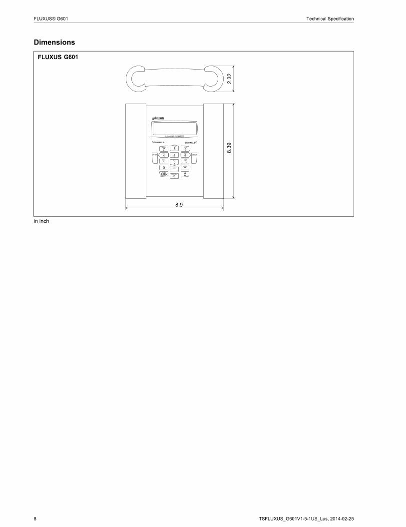
Dimensions
FLUXUS
in inch
G601
!
" # " $ %
8.9
2.3
28
.39

TSFLUXUS_G601V1-5-1US_Lus, 2014-02-25 9
Technical Specification FLUXUS® G601
Standard Scope of Supply
G601 Standard G601 Extended Standard
G601 Multifunctional
G601 CA-Energy
application flow measurement on gas flow measurement on compressed air, industrial gases and liquids
2 independent measuring channelscalculation of standard volumetric flow rate
calculation of standard volumetric flow rate, with optional use of current measured pressure and temperature valuesincluding energy calculator for BTU and heat measurements
simultaneous monitoring of 2 energy flows
liquids: integrated heat flow computer for monitoring of energy flows
outputspassive current output 2 2 2 2binary output 2 1 2 2frequency output - 1 1 -inputstemperature input - - 1 2passive current input - 2 2 2voltage input - - 1 -accessoriestransport case x x x xpower supply unit, mains cable
x x x x
battery x x x xoutput adapter - - x -input adapter - 2 2 2adapter for voltage and current inputs
- - 3 2
QuickFix pipe mounting fixture for transmitter
x x x x
serial data kit x x x xmeasuring tape x x x xwall thickness probe - - x xuser manual,Quick Start Guide
x x x x
connector board at the upper side of the transmitter
! $ ! "
& ' ( & '
! !
! $ ! "
& ' ( & '
) ( & '
* *
! !
! $ ! "
& ' ( & '
) ( & '
* *
! !
+ + +
! $ ! "
& ' ( & '
) ( & '
* *
! !
10 TSFLUXUS_G601V1-5-1US_Lus, 2014-02-25
FLUXUS® G601 Technical Specification
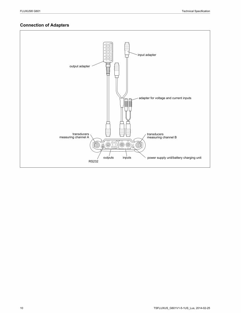
Connection of Adapters
! $ ! "
& ' ( & '
) ( & '
* *
! !
+ + +
&'(&'
output adapter
input adapter
adapter for voltage and current inputs
transducersmeasuring channel A
RS232outputs inputs
transducersmeasuring channel B
power supply unit/battery charging unit

TSFLUXUS_G601V1-5-1US_Lus, 2014-02-25 11
Technical Specification FLUXUS® G601
Example for the Equipment of a Transport Case
serial data kit
power supply unit, mains cable
transducer mounting fixture
measuring tape
transmittertransducers
user manual,Quick Start Guide
coupling compoundwall thickness probe (optional)
QuickFix pipe mounting fixture
temperature probes (optional)
12 TSFLUXUS_G601V1-5-1US_Lus, 2014-02-25
FLUXUS® G601 Technical Specification
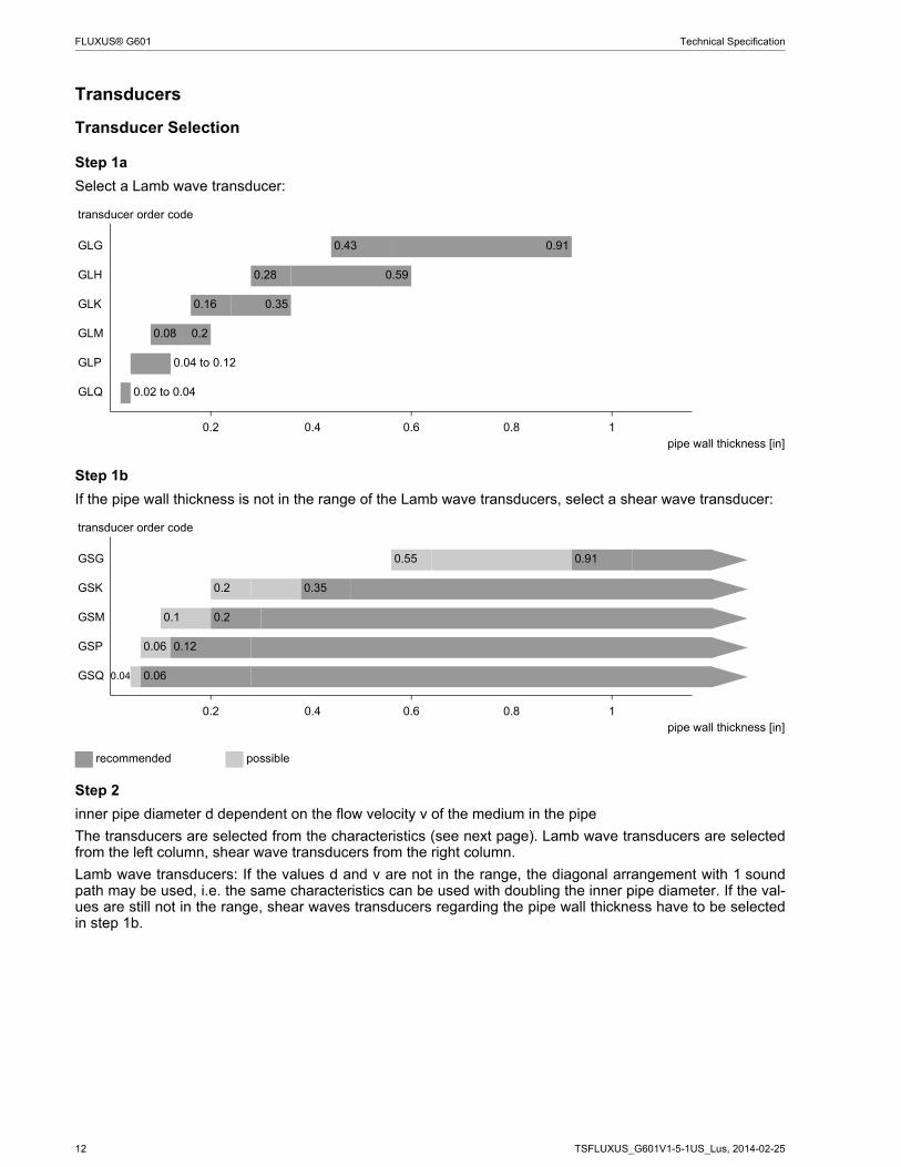
Transducers
Transducer Selection
Step 1a
Select a Lamb wave transducer:
Step 1b
If the pipe wall thickness is not in the range of the Lamb wave transducers, select a shear wave transducer:
Step 2
inner pipe diameter d dependent on the flow velocity v of the medium in the pipe
The transducers are selected from the characteristics (see next page). Lamb wave transducers are selectedfrom the left column, shear wave transducers from the right column.
Lamb wave transducers: If the values d and v are not in the range, the diagonal arrangement with 1 soundpath may be used, i.e. the same characteristics can be used with doubling the inner pipe diameter. If the val-ues are still not in the range, shear waves transducers regarding the pipe wall thickness have to be selectedin step 1b.
transducer order code
GLG 0.43 0.91
GLH 0.28 0.59
GLK 0.16 0.35
GLM 0.08 0.2
GLP 0.04 to 0.12
GLQ 0.02 to 0.04
0.2 0.4 0.6 0.8 1pipe wall thickness [in]
transducer order code
GSG 0.55 0.91
GSK 0.2 0.35
GSM 0.1 0.2
GSP 0.06 0.12
GSQ 0.04 0.06
0.2 0.4 0.6 0.8 1pipe wall thickness [in]
recommended possible

TSFLUXUS_G601V1-5-1US_Lus, 2014-02-25 13
Technical Specification FLUXUS® G601
Lamb wave transducer1 shear wave transducer1
GLG GSG
GLH
GLK GSK
GLM GSM
GLP GSP
GLQ GSQ
1 inner pipe diameter and max. flow velocity for a typical application with natural gas, nitrogen, oxygen in reflect arrangement with2 sound paths (Lamb wave transducers)/1 sound path (shear wave transducers)
0 20 40 60 80 100 120vfts
10
20
30
40
DinGRG
0 20 40 60 80 100 120vfts
10
20
30
40
Din
0 20 40 60 80 100 120vfts
10
20
30
40
DinGRH
0 20 40 60 80 100 120vfts
5
10
15
20Din
0 20 40 60 80 100 120vfts
5
10
15
20Din
0 20 40 60 80 100 120vfts
1
2
3
4
DinGRM
0 20 40 60 80 100 120vfts
1
2
3
4
DinGDM
0 20 40 60 80 100 120vfts
0.5
1.0
1.5
2.0
2.5Din
GRP
0 20 40 60 80 100 120vfts
0.5
1.0
1.5
2.0
2.5Din
GDP
0 20 40 60 80 100 120vfts
0.5
1.0
1.5
2.0
2.5Din
GRQ
0 20 40 60 80 100 120vfts
0.5
1.0
1.5
2.0
2.5Din
GDQ

14 TSFLUXUS_G601V1-5-1US_Lus, 2014-02-25
FLUXUS® G601 Technical Specification
Step 3
min. medium pressure
Example
Step 4
for the characters 4 to 11 of the transducer order code (ambient temperature, explosion protection, connectionsystem, extension cable) see page 15
Step 5
for the technical data of the selected transducer see page 16 et seqq.
Lamb wave transducer shear wave transducertransducer order code
medium pressure1 [psi] transducer order code
medium pressure1 [psi]metal pipe plastic pipe metal pipe plastic pipe
min. min. extended min. min. min. extended min.GLG 218 145 15 GSG 435 290 15
GLH 218 145 15 GSK 435 290 15
GLK 218 (d > 4.7 in)145 (d < 4.7 in)
145 (d > 4.7 in)73 (d < 4.7 in)
15 GSM 435 290 15
GLM 145 (d > 2.4 in)73 (d < 2.4 in)
- 15 GSP 435 290 15
GLP 145 (d > 1.4 in)73 (d < 1.4 in)
- 15 GSQ 435 290 15
GLQ 145 (d > 0.59 in)73 (d < 0.59 in)
- 15
1 depending on application, typical absolute value for natural gas, nitrogen, compressed air
d = inner pipe diameter
step1 pipe wall thickness in 0.47 0.47 0.47 1.2
selected transducer GLG or GLH GLG or GLH GLG or GLH GS2 inner pipe diameter in 31.5 23.6 31.5 11.8
max. flow velocity ft/s 49 49 98 49selected transducer GLG GLG or GLH values not in the range
of the characteristics, but by using direct mode, the inner pipe diameter in the cha-racteristics is doubled:GLG
GSK
3 min. medium pressure psi 247 247 247 508selected transducer GLG GLG or GLH
influence of acoustic noise is reduced with increased transducer frequency, thus recommended:GLH
GLG GSK
TSFLUXUS_G601V1-5-1US_Lus, 2014-02-25 15
Technical Specification FLUXUS® G601
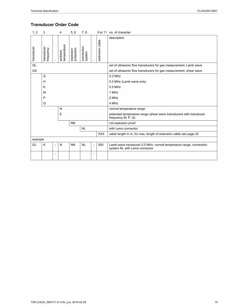
Transducer Order Code
1, 2 3 4 5, 6 7, 8 9 to 11 no. of charactertr
ansd
ucer
tran
sduc
er
freq
uenc
y
- am
bien
t te
mpe
ratu
re
exp
losi
on
pro
tect
ion
conn
ect
ion
syst
em
- ext
ensi
on c
able
description
GL set of ultrasonic flow transducers for gas measurement, Lamb wave
GS set of ultrasonic flow transducers for gas measurement, shear wave
G 0.2 MHz
H 0.3 MHz (Lamb wave only)
K 0.5 MHz
M 1 MHz
P 2 MHz
Q 4 MHz
N normal temperature range
E extended temperature range (shear wave transducers with transducer frequency M, P, Q)
NN not explosion proof
NL with Lemo connector
XXX cable length in m, for max. length of extension cable see page 25
example
GL K - N NN NL - 000 Lamb wave transducer 0.5 MHz, normal temperature range, connection system NL with Lemo connector
- -

16 TSFLUXUS_G601V1-5-1US_Lus, 2014-02-25
FLUXUS® G601 Technical Specification
Technical Data
Shear Wave Transducers
technical type GDG1NZ7 GDK1NZ7order code GSG-NNNNL GSK-NNNNLtransducer frequency MHz 0.2 0.5
medium pressure1
min. extended psi metal pipe: 290 metal pipe: 290min. psi metal pipe: 435
plastic pipe: 15metal pipe: 435plastic pipe: 15
inner pipe diameter d2
min. extended in 9.8 2.8min. recommended in 15 3.1max. recommended in 31.9 19.7max. extended in 43.3 28.3pipe wall thicknessmin. in 0.55 0.2max. in - -materialhousing PEEK with stainless steel
cap 304PEEK with stainless steel cap 304
contact surface PEEK PEEKdegree of protection NEMA 6 NEMA 6transducer cabletype 1699 1699length ft 16 16dimensionslength l in 5.1 4.98width b in 2.01 2.01height h in 2.64 2.66dimensional drawing
ambient temperaturemin. °F -40 -40max. °F +266 +266temperature compensation
x x
1 depending on application, typical absolute value for natural gas, nitrogen, compressed air2 shear wave transducer:
typical values for natural gas, nitrogen, oxygen, pipe diameters for other gases on requestpipe diameter min. recommended/max. recommended/max. extended: in diagonal arrangement and for a flow velocity of 49 ft/s
l
hb
l
hb
TSFLUXUS_G601V1-5-1US_Lus, 2014-02-25 17
Technical Specification FLUXUS® G601
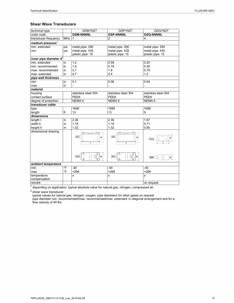
Shear Wave Transducers
technical type GDM1NZ7 GDP1NZ7 GDQ1NZ7order code GSM-NNNNL GSP-NNNNL GSQ-NNNNLtransducer frequency MHz 1 2 4
medium pressure1
min. extended psi metal pipe: 290 metal pipe: 290 metal pipe: 290min. psi metal pipe: 435
plastic pipe: 15metal pipe: 435plastic pipe: 15
metal pipe: 435plastic pipe: 15
inner pipe diameter d2
min. extended in 1.2 0.59 0.24min. recommended in 1.6 0.79 0.39max. recommended in 3.1 1.6 0.79max. extended in 4.7 2.4 1.2pipe wall thicknessmin. in 0.1 0.06 0.04max. in - - -materialhousing stainless steel 304 stainless steel 304 stainless steel 304contact surface PEEK PEEK PEEKdegree of protection NEMA 6 NEMA 6 NEMA 6transducer cabletype 1699 1699 1699length ft 13 13 9dimensionslength l in 2.36 2.36 1.67width b in 1.18 1.18 0.71height h in 1.32 1.32 0.85dimensional drawing
ambient temperaturemin. °F -40 -40 -40max. °F +266 +266 +266temperature compensation
x x x
remark on request1 depending on application, typical absolute value for natural gas, nitrogen, compressed air2 shear wave transducer:
typical values for natural gas, nitrogen, oxygen, pipe diameters for other gases on requestpipe diameter min. recommended/max. recommended/max. extended: in diagonal arrangement and for a flow velocity of 49 ft/s
hb
l
hb
l
hb
l

18 TSFLUXUS_G601V1-5-1US_Lus, 2014-02-25
FLUXUS® G601 Technical Specification
Shear Wave Transducers (extended temperature range)
technical type GDM1EZ7 GDP1EZ7 GDQ1EZ7order code GSM-ENNNL GSP-ENNNL GSQ-ENNNLtransducer frequency MHz 1 2 4
medium pressure1
min. extended psi metal pipe: 290 metal pipe: 290 metal pipe: 290min. psi metal pipe: 435
plastic pipe: 15metal pipe: 435plastic pipe: 15
metal pipe: 435plastic pipe: 15
inner pipe diameter d2
min. extended in 1.2 0.59 0.24min. recommended in 1.6 0.79 0.39max. recommended in 3.1 1.6 0.79max. extended in 4.7 2.4 1.2pipe wall thicknessmin. in 0.1 0.06 0.04max. in - - -materialhousing stainless steel 304 stainless steel 304 stainless steel 304contact surface Sintimid Sintimid Sintimiddegree of protection NEMA 4 NEMA 4 NEMA 4transducer cabletype 1699 1699 1699length ft 13 13 9dimensionslength l in 2.36 2.36 1.67width b in 1.18 1.18 0.71height h in 1.32 1.32 0.85dimensional drawing
ambient temperaturemin. °F -22 -22 -22max. °F +392 +392 +392temperature compensation
x x x
remark on request1 depending on application, typical absolute value for natural gas, nitrogen, compressed air2 shear wave transducer:
typical values for natural gas, nitrogen, oxygen, pipe diameters for other gases on requestpipe diameter min. recommended/max. recommended/max. extended: in diagonal arrangement and for a flow velocity of 49 ft/s
hb
l
hb
l
hb
l

TSFLUXUS_G601V1-5-1US_Lus, 2014-02-25 19
Technical Specification FLUXUS® G601
Lamb Wave Transducers
technical type GRG1NC3 GRH1NC3 GRK1NC3order code GLG-NNNNL GLH-NNNNL GLK-NNNNLtransducer frequency MHz 0.2 0.3 0.5
medium pressure1
min. extended psi metal pipe: 145 metal pipe: 145 metal pipe:145 (d > 4.7 in)73 (d < 4.7 in)
min. psi metal pipe: 218plastic pipe: 15
metal pipe: 218plastic pipe: 15
metal pipe:218 (d > 4.7 in)145 (d < 4.7 in)plastic pipe: 15
inner pipe diameter d2
min. extended in 7.5 4.7 2.4min. recommended in 8.7 5.5 3.1max. recommended in 35.4 23.6 11.8max. extended in 63 39.4 19.7pipe wall thicknessmin. in 0.43 0.28 0.16max. in 0.91 0.59 0.35materialhousing PPSU with stainless steel
cap 304PPSU with stainless steel cap 304
PPSU with stainless steel cap 304
contact surface PPSU PPSU PPSUdegree of protection NEMA 4 NEMA 4 NEMA 4transducer cabletype 1699 1699 1699length ft 16 16 16dimensionslength l in 5.06 5.06 5.06width b in 2.01 2.01 2.01height h in 2.66 2.66 2.66dimensional drawing
ambient temperaturemin. °F -40 -40 -40max. °F +338 +338 +338temperature compensation
x x x
1 depending on application, typical absolute value for natural gas, nitrogen, compressed air2 Lamb wave transducer:
typical values for natural gas, nitrogen, oxygen, pipe diameters for other gases on requestpipe diameter min. recommended/max. recommended: in reflect arrangement and for a flow velocity of 49 ft/spipe diameter max. extended: in diagonal arrangement and for a flow velocity of 82 ft/s
l
hb
l
hb
l
hb

20 TSFLUXUS_G601V1-5-1US_Lus, 2014-02-25
FLUXUS® G601 Technical Specification
Lamb Wave Transducers
technical type GRM1NC3 GRP1NC3 GRQ1NC3order code GLM-NNNNL GLP-NNNNL GLQ-NNNNLtransducer frequency MHz 1 2 4
medium pressure1
min. extended psi - - -min. psi metal pipe:
145 (d > 2.4 in)73 (d < 2.4 in)plastic pipe: 15
metal pipe:145 (d > 1.4 in)73 (d < 1.4 in)plastic pipe: 15
metal pipe:145 (d > 0.59 in)73 (d < 0.59 in)plastic pipe: 15
inner pipe diameter d2
min. extended in 1.2 0.59 0.28min. recommended in 1.6 0.79 0.39max. recommended in 3.5 2 0.87max. extended in 5.9 2.8 1.4pipe wall thicknessmin. in 0.08 0.04 0.02max. in 0.2 0.12 0.04materialhousing PPSU with stainless steel
cap 304PPSU with stainless steel cap 304
PPSU with stainless steel cap 304
contact surface PPSU PPSU PPSUdegree of protection NEMA 4 NEMA 4 NEMA 4transducer cabletype 1699 1699 1699length ft 13 13 9dimensionslength l in 2.91 2.91 1.65width b in 1.26 1.26 0.87height h in 1.59 1.59 1dimensional drawing
ambient temperaturemin. °F -40 -40 -40max. °F +338 +338 +338temperature compensation
x x x
remark on request1 depending on application, typical absolute value for natural gas, nitrogen, compressed air2 Lamb wave transducer:
typical values for natural gas, nitrogen, oxygen, pipe diameters for other gases on requestpipe diameter min. recommended/max. recommended: in reflect arrangement and for a flow velocity of 49 ft/spipe diameter max. extended: in diagonal arrangement and for a flow velocity of 82 ft/s
l
hb
l
hb
lh
b
TSFLUXUS_G601V1-5-1US_Lus, 2014-02-25 21
Technical Specification FLUXUS® G601
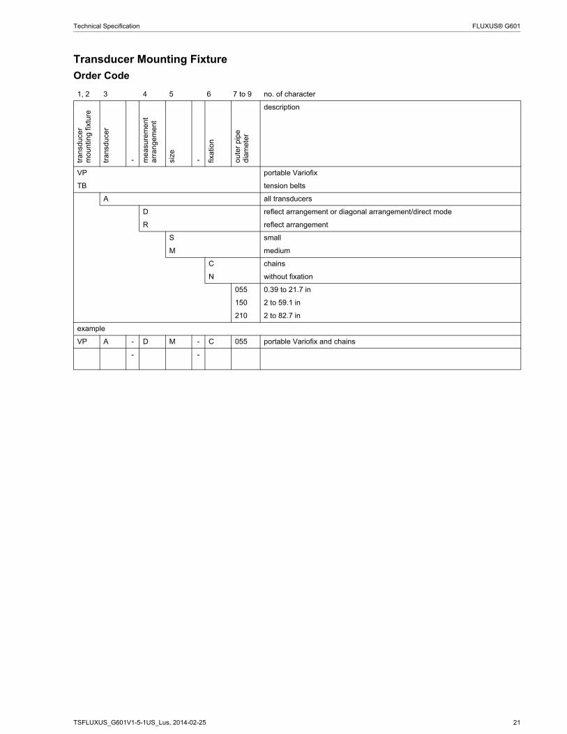
Transducer Mounting Fixture
Order Code
1, 2 3 4 5 6 7 to 9 no. of character
tran
sduc
er
mo
untin
g fi
xtur
e
tran
sduc
er
- me
asur
emen
t a
rran
gem
ent
size
- fixat
ion
out
er p
ipe
dia
met
er
description
VP portable Variofix
TB tension belts
A all transducers
D reflect arrangement or diagonal arrangement/direct mode
R reflect arrangement
S small
M medium
C chains
N without fixation
055 0.39 to 21.7 in
150 2 to 59.1 in
210 2 to 82.7 in
example
VP A - D M - C 055 portable Variofix and chains
- -

22 TSFLUXUS_G601V1-5-1US_Lus, 2014-02-25
FLUXUS® G601 Technical Specification
portable Variofix VP and chains
material: stainless steel 304, 301, 303
dimensions:16.3 x 3.7 x 2.99 in
chain length: 6 ft
portable Variofix VP and magnet (optional)
material: stainless steel 304, 301, 303
dimensions:16.3 x 3.7 x 1.57 in
tension belts TB
material: steel, powder coated and textile tension belt
length: 16/22 ft
ambient temperature:max. 140 °F
outer pipe diameter:max. 59.1/82.7 in
(optional)
(optional)

TSFLUXUS_G601V1-5-1US_Lus, 2014-02-25 23
Technical Specification FLUXUS® G601
Coupling Materials for Transducers
Technical Data
normal temperature range(4th character of transducer order code = N)
extended temperature range(4th character of transducer order code = E)
< 212 °F < 338 °F < 302 °F < 392 °Fcoupling compound type N coupling compound type E coupling compound type E coupling compound
type E or H
type order code ambient temperature material°F
coupling compound type N
990739-1 -22 to +266 mineral grease paste
coupling compound type E
990739-2 -22 to +392 silicone paste
coupling compound type H
990739-3 -22 to +482 fluoropolymer paste

24 TSFLUXUS_G601V1-5-1US_Lus, 2014-02-25
FLUXUS® G601 Technical Specification
Damping Mats (optional)Damping mats will be used for the gas measurement to reduce acoustic noise influences on the measure-ment.
Transducer damping mats will be installed below the transducers.
Pipe damping mats will be installed at reflection points, e.g. flange, weld.
Selection of Damping Mats
type description outer pipe diameter
dimensionsl x b x h
transducer frequency
techni-cal type
ambient temperature
remark
in in G H K M P °Ftransducer damping matD for temporary installation
(multiple use), fixed with coupling compound
< 3.1 17.72 x 4.53 x 0.02 - - - x x D20S3 -13 to +140≥ 3.1 35.43 x 9.06 x 0.02 - - x x - D20S2
35.43 x 9.06 x 0.05 x x - - - D50S2pipe damping matA for temporary installation
(multiple use), fixed with coupling compound
< 11.8 11.81 x 4.53 x 0.02 x x x x x A20S4 -13 to +140 for quantity see table below
B self-adhesive ≥ 11.8 l x 3.94 x 0.04 x x x x x B35R2 -31 to +122 l - see table below
Quantity for Pipe Damping Mat - type A(depending on the outer pipe diameter)
outer pipe diameter D transducer frequencyin G, H K, M, P
3.9 12 67.9 24 1211.8 32 16
Length of Pipe Damping Mat - type B(length l depending on transducer frequency and outer pipe diameter)
outer pipe diameter D transducer frequencyG, H K, M, P
in ft ft11.8 39 1919.7 104 5239.4 413 206
b
lD
transducer damping mat pipe damping mat
reflect arrangementdiagonal arrangement/direct mode
D = outer pipe diameter
reflection point

TSFLUXUS_G601V1-5-1US_Lus, 2014-02-25 25
Technical Specification FLUXUS® G601
Connection Systems
Transducer Cable
Technical Data
connection system NL
transducer frequency(3d character of transducer
order code)
G, H, K M, P Q S
NL
x y l1 x y l1 x y l1 x y lcable length ft 6 9 ≤ 82 6 6 ≤ 82 6 3 ≤ 82 3 3 ≤ 65
1 > 82 to 328 ft on request
x, y = transducer cable lengthl = max. length of extension cable
transducer cable extension cabletype 1699 2551 1750standard length ft see table above 16
32max. length ft - see table above 32ambient temperature °F -67 to +392 -13 to +176 < 144sheathmaterial stainless steel 304 - -outer diameter in 0.31 - -cable jacketmaterial PTFE TPE-O PEouter diameter in 0.11 0.31 0.24thickness in 0.01 0.02color brown black blackshield x x x
tran
smitt
er
l x y
-

26 TSFLUXUS_G601V1-5-1US_Lus, 2014-02-25
FLUXUS® G601 Technical Specification
Clamp-on Temperature Probe (optional)
Technical Data
Connection
Temperature Probe
Connector
Cable
technical type PT13N PT13N PT13F PT13Forder code 670413-1 670412-1 670413-2 670412-2design short response timetype Pt1000 2x Pt1000 matched
according to EN 1434-1Pt1000 2x Pt1000 matched
according to EN 1434-1connection 4-wire 4-wiremeasuring range °F -22 to +482 -58 to +482
accuracy T ±(0.27 °F + 2 . 10-3 . (|T [°F]| - 32 °F)), class A ±(0.27 °F + 2 . 10-3 . (|T [°F]| - 32 °F)), class Aaccuracy ∆T - ≤ 0.1 K, (3 K < ∆T < 6 K),
more corresponding to EN 1434-1
- ≤ 0.1 K, (3 K < ∆T < 6 K), more corresponding to EN 1434-1
response time s 50 8housing aluminum PEEK, stainless steel 304, copperdegree of protection NEMA 4 NEMA 4weight (without con-nector)
lb 0.6 1.1 0.7 1.4
fixation clamp-on clamp-onaccessoriesthermal conductivity paste 392 °F
x x
thermal conductivity foil 482 °F
x x
plastic protection plate, insulation foam
- x
dimensionslength l in 0.59 0.55width b in 0.59 1.18height h in 0.79 1.06dimensional drawing A B
pin cable of temperature probe extension cable1 white/blue blue2 red/blue gray3, 4, 5 not connected6 red red7 white white8 not connected
cable of temperature probe extension cabletype 4 x 0.25 mm² black or white LIYCY 8 x 0.14 mm² graystandard length ft 9 16/32/82
max. length ft - 656
cable jacket PTFE PVC
h
l
extension cable
h
l
A
B
red/blue red white/blue white

TSFLUXUS_G601V1-5-1US_Lus, 2014-02-25 27
Technical Specification FLUXUS® G601
Wall Thickness Measurement (optional)The pipe wall thickness is an important pipe parameter which has to be determined exactly for a good mea-surement. However, the pipe wall thickness often is unknown.
The wall thickness probe can be connected to the transmitter instead of the flow transducers and the wallthickness measurement mode is activated automatically.
Acoustic coupling compound is applied to the wall thickness probe which then is placed firmly on the pipe.The wall thickness is displayed and can be stored directly in the transmitter.
Technical Data
Cable
technical type DWR1NZ7
measuring range1 in 0.04 to 9.8resolution in 0.0004accuracy 1 % ± 0.004 inmedium temperature °F -4 to +392,
short-time peak max. 932сabletype 2616length ft 4
1 The measuring range depends on the attenuation of the ultrasonic signal in thepipe. For strongly attenuating plastics (e.g. PFA, PTFE, PP) the measuring range is smaller.
type 2616ambient temperature °F <392cable jacketmaterial FEPouter diameter in 0.2color blackshield x
DWR1NZ7

28 TSFLUXUS_G601V1-5-1US_Lus, 2014-02-25
FLUXUS® G601 Technical Specification
FLEXIM AMERICAS Corporation
Edgewood, NY 11717
USA
Tel.: (631) 492-2300
Fax: (631) 492-2117
internet: www.flexim.com
e-mail: [email protected]
1-888-852-7473
Subject to change without notification. Errors excepted.
FLUXUS® is a registered trademark of FLEXIM GmbH.