
technical spec
298
TECHNICAL SPECIFICATION CONTENT ITEM NO SUB DESCRIPTION PAGE NO E1 SCOPE OF WORK 1-4 E2 GENERAL TECHNICAL CLAUSES & DESIGN 1-42 E3 SYSTEM AND CLIMATIC CONDITION 1-4 E4 INDOOR SWITCHGEAR GIS/AIS/CONTAINERISED 1-58 (CONTROL PANEL, VCB, CT,DISCONNECTOR, PROTECTION RELAY, MULTI FUNCTIONAL METER) E5 OUT DOOR EQUIPMENT I POWER TRANSFORMER 1-61 II STATION TRANSFORMER 1-31 III 33KV VCB 1-10 IV 11KV & 33KV CT 1-15 V 11KV & 33KV IVT 1-15 VI 11KV & 33KV SURGE ARRESTOR 1-17 VII 33KV ISOLATOR 1-14 VIII 11KV & 33KV AB SWITCH 1-16 IX SUB STATION STRUCTURE 1-6 E6 BATTERY AND BATTERY CHARGER 1-22 E7 AC DISTRIBUTION BOARD & DC DISTRIBUTION BOARD 1-20 E8 CONTROL AND PROTECTION PANEL 1-23 E9 CONTOL CABLE & XLPE CABLES 1-26 E10 LINE MATERIALS I JOIST POLE & PSC POLE 1-14 II V CROSS ARM, BACK CLAMP AND F CLAMP 1-7 III HT STAY SET & STAY INSULATOR 1-9 E11 RTU FOR SCADA COMPATIBILITY 1-18 E12 COMMON MATERIALS FOR SUBSTATION AND LINE I AAA CONDUCTOR 1-13 II INSULATOR (DISC TYPE) 1-22 III INSULATOR (PIN AND STATION TYPE) 1-6 IV INSULATOR (POLYMER TYPE) 1-23 V HARD WARE FITTINGS 1-11 VI CLAMP AND CONNECTOR 1-8 VII HG FUSE 1-12 VIII CABLE TERMINATIN AND JOINTING KIT 1-14 IX LT DISTRIBUTION BOX 1-9 E13 EARTHING AND EARTHING COIL 1-11 E14 33KV & 11KV LINE AND ERECTION 1-78 E15 CIVIL WORKS AND FIRE FIGHTING WALL 1-52 E16 FIRE FIGHTING AND FIRE DETECTION SYSTEM 1-10 E17 SUBSTATION AND CONTROL ROOM LIGHTING 1-23 E18 AIR CONDITIONING SYSTEM 1-4 E19 TESTING EQUIPMENTS , MAINTENANCE TOOLS, T&P, OFFICE EQUIPMENT AND FURNITURES 1-10
description
good doc
Transcript of technical spec

TECHNICAL SPECIFICATION CONTENT
ITEM NO SUB DESCRIPTION PAGE NO
E1 SCOPE OF WORK 1-4 E2 GENERAL TECHNICAL CLAUSES & DESIGN 1-42 E3 SYSTEM AND CLIMATIC CONDITION 1-4 E4 INDOOR SWITCHGEAR GIS/AIS/CONTAINERISED 1-58
(CONTROL PANEL, VCB, CT,DISCONNECTOR, PROTECTION RELAY, MULTI FUNCTIONAL METER)
E5 OUT DOOR EQUIPMENT I POWER TRANSFORMER 1-61 II STATION TRANSFORMER 1-31 III 33KV VCB 1-10 IV 11KV & 33KV CT 1-15 V 11KV & 33KV IVT 1-15 VI 11KV & 33KV SURGE ARRESTOR 1-17 VII 33KV ISOLATOR 1-14 VIII 11KV & 33KV AB SWITCH 1-16 IX SUB STATION STRUCTURE 1-6
E6 BATTERY AND BATTERY CHARGER 1-22 E7 AC DISTRIBUTION BOARD & DC DISTRIBUTION BOARD 1-20 E8 CONTROL AND PROTECTION PANEL 1-23 E9 CONTOL CABLE & XLPE CABLES 1-26
E10 LINE MATERIALS I JOIST POLE & PSC POLE 1-14 II V CROSS ARM, BACK CLAMP AND F CLAMP 1-7 III HT STAY SET & STAY INSULATOR 1-9
E11 RTU FOR SCADA COMPATIBILITY 1-18 E12 COMMON MATERIALS FOR SUBSTATION AND LINE
I AAA CONDUCTOR 1-13 II INSULATOR (DISC TYPE) 1-22 III INSULATOR (PIN AND STATION TYPE) 1-6 IV INSULATOR (POLYMER TYPE) 1-23 V HARD WARE FITTINGS 1-11 VI CLAMP AND CONNECTOR 1-8 VII HG FUSE 1-12 VIII CABLE TERMINATIN AND JOINTING KIT 1-14 IX LT DISTRIBUTION BOX 1-9
E13 EARTHING AND EARTHING COIL 1-11 E14 33KV & 11KV LINE AND ERECTION 1-78 E15 CIVIL WORKS AND FIRE FIGHTING WALL 1-52 E16 FIRE FIGHTING AND FIRE DETECTION SYSTEM 1-10 E17 SUBSTATION AND CONTROL ROOM LIGHTING 1-23 E18 AIR CONDITIONING SYSTEM 1-4
E19 TESTING EQUIPMENTS , MAINTENANCE TOOLS, T&P, OFFICE EQUIPMENT AND FURNITURES 1-10

E20 MANDATORY SPARES(PROVIDED IN THE PRICE SCHEDULE) AS PER PRICE SCHEDULE
E21 I GTP AS ENCLOSED
II SINGLE LINE DIAGRAM, SCHEMATIC LAYOUT OF SUBSTATION AND OTHER DRAWINGS AS ENCLOSED
E22 TOPO GRAPH E23 VENDOR LIST AS ENCLOSED
ODISHA POWER TRANSMISSION CORPORATION LTD
(A Govt. of Odisha Undertaking) Regd. Office, Jan path , Bhubaneswar - 751022
ODISHA DISTRIBUTION SYSTEM STRENGTHING PROJECT
(ODSSP)
PROJECT MANAGEMENT UNIT
VOL – II Technical Specification
For Engineering, Supply, Erection & Commissioning of
33/11kV Sub-stations With associated lines

VOL-II(TS) E1-SCOPE OF WORK Page 1 of 4
SCOPE OF WORK

VOL-II(TS) E1-SCOPE OF WORK Page 2 of 4
1.0 SCOPE OF WORK:
1.1 Scope of Work for Sub-station & Line Bidders are requested to visit the site before participating in the tender.
Scope of work of the Contractor includes Engineering, Supply, Erection, Testing and Commissioning of all materials & equipment such as – Sub-station:
a) 33/11kV Power Transformer b) 33/0.4kV, 100 kVA Station Transformer c) 33kV GIS Indoor Switchgear containing Busbar, VCB, Disconnector, CT,
CVT/PT d) 33kV AIS Indoor Switchgear containing Busbar, VCB, CT, CVT/PT e) 11kV AIS Switchgear containing Busbar, VCB, CT, CVT/PT f) Control & Relay Panel with multi-functional Meter g) RTU for SCADA h) Distribution Box for both AC & DC i) Conductors, Insulators, Hardware fitting and Clamps & Connector j) Battery & Battery charger k) Out door 33 KV VCB l) Isolators m) Surge Arresters n) AB Switches (for 33 and 11 kV), HG fuses (for 33 and 11 kV), o) XLPE HT cable, Power Cables & its jointing kits, Control Cables & its
termination p) Substation Structures q) Earthing r) Control Room Cum office Building (Reinforcement bars, cements,
different type of aggregates, bricks,plastering,Flooring,Water supply arrangement,Sanitation,Colouring,Fixing of doors & windows,Illumination,Fire & smoke detection facility etc)
s) Air Conditioner for the building. t) Fire Fighting equipment u) Fencing v) Boundary wall w) Road x) Fire fighting wall y) Site surfacing including antiweed treatment. z) Switchyard illumination.

VOL-II(TS) E1-SCOPE OF WORK Page 3 of 4
aa) Concrete Cable trench. bb) Fixing of danger plate,Bay marking & colour coding cc) Excavation of soil for foundation works for the structure & transformer dd) Leveling of sub-station area including borrowed earth.
Line:-
a) Survey of 33 & 11 KV line. b) Preparation of pole schedule c) Erection of Joist & PSC poles including civil works. d) Stringing of conductors e) Erection of insulators & other hardware fittings. f) Erection of stay wires with insulator g) Earthing of poles. h) Fixing of number plates etc.
Important Note: Wherever the source is from an existing 33 KV or Grid sub-station to the proposed 33/11 KV s/s, care is to be taken for construction of bays at the existing s/s end for matching with the existing system. The dismantling works if any involved are also to be taken care as per the direction of the Engineer in Charge.
1.2 The specification covers design, engineering, manufacture, assembly, type
tests, inspection and testing at manufacturer’s works, packing, forwarding and delivery F.O.R destination stores of single phase, single unit Potential Transformers for instrumentation, protection and metering services in solidly grounded 33/11KV S/s under OPTCL.
1.3 The scope is on the basis of a single/JV Bidder’s responsibility, completely covering supply and erection of all the equipment specified under the accompanying Technical Specifications including other services. It will include the following:
a) A tentative BOQ has been made on Preliminary investigation / survey. However, the Contractor will make detail survey and will supply the materials as per detailed survey / investigation.
b) Providing Engineering drawings related to foundation details, structural details of both line & Sub-station work.
c) Providing Equipment data, Operational manual.

VOL-II(TS) E1-SCOPE OF WORK Page 4 of 4
d) Preparation of Cable Schedule (in shape of a booklet) etc for the Owner’s approval.
e) Packing and transportation from the manufacturer’s works to the site. f) Loading, unloading and transportation as required. g) Receipt, storage, preservation and conservation of equipment at the site
including insurance. h) Erection, testing and commissioning of all the equipment. i) Performance and guarantee tests on completion of commissioning.
1.4 Specific Exclusions-
The following items of work are specifically excluded from the Contractors scope of work unless otherwise specifically brought out.
a) Sub-station site selection b) Land acquisition for sub-station
c) For line the route survey is in the scope of the Contractor as per the direction of the Engineer in charge.
1.5 Limit of Contract
The scope of work shall also include all work incidentals for successful operation and commissioning and handing over of works whether specifically mentioned or not. In general, works are to be carried out by the Contractor in accordance with the stipulations in Conditions of Contract.
VOL-II(TS) E2- GENERAL TECHNICAL CLAUSES & DESIGN Page 1 of 42
PART - A
GENERAL TECHNICAL CLAUSES
VOL-II(TS) E2- GENERAL TECHNICAL CLAUSES & DESIGN Page 2 of 42
TABLE OF CONTENTS OF
GENERAL TECHNICAL CLAUSES
NO DESCRIPTION PAGENO. PART-A (GENERAL TECHNICAL CLAUSES)
1.0 General particulars of system 3
2.0 Layout arrangement: 3
3.0 Soil data 4
4.0 Completeness and accuracy of information 4
5.0 Drawings attached with tender document 4
6.0 Compliance with specification 4
7.0 Test and maintenance equipment 5
8.0 Spares 5
9.0 Training 6
10.0 Erection at site and accommodation 7
11.0 Compliance with regulations 7
12.0 Insurance 8
PART –B (GENERAL TECHNICAL CLAUSES FOR DESIGN)
1.0 Design & standardisation 11
2.0 Quality assurance 12
3.0 Health, safety & environment (HSE) 14
4.0 Progress reporting 14
5.0 Standards 16
6.0 Language & system of units 16
7.0 Correspondence, drawing, approval procedure and sample 16
8.0 General requirements 20
9.0 Production progress requirements 30
10.0 Wiring, cabling & cable installation 30
11.0 Construction management 39
12.0 Code requirements 40
13.0 Owner’s supervision 40
14.0 Testing & inspection 40
15.0 Fire precaution 41
16.0 Packing, shipping & transport 42
17.0 Erection marks 43
18.0 Spanners & special tools 43
19.0 Runway beams, eyebolts & lifting tackle
44

VOL-II(TS) E2- GENERAL TECHNICAL CLAUSES & DESIGN Page 3 of 42
1. 0 GENERAL PARTICULARS OF SYSTEM
1.1 Substation Philosophy:
There will be three types of substations.
i. GIS Indoor substation – 33 kV side will be with GIS Indoor switch gear panel and 11 kV side will be with AIS Indoor switch gear panel in urban and town areas
ii. AIS Indoor substation – 33 kV side will be with AIS Indoor switch gear panel and 11 kV side will be with AIS Indoor switch gear panel in rural areas
iii. Containiser GIS Substation (E-House) in five selected places
1.2 Line Philosophy: i. 33 kV incoming lines and 11 kV out going lines. to/from GIS sub
stations and containiser sub stations will be with 11 mtr Galvanised RS Joist
ii. 33 kV incoming lines to AIS sub stations will be with 11 mtr Galvanised RS Joist. and 11 kV out going lines will be with 10 mtr (300 kg capacity) PSC pole pin points and (400 kg capacity) for cut points
iii. All 33 kV lines will be with 148 sq mm All Aluminium Alloy Conductor (AAAC) and 11 kV lines with 100 sq mm AAAC
1.3 Transformer Capacity: In GIS and Containiser GIS sub stations, the transformers will be of
2X5 MVA or 2X8MVA capacity. In AIS substations, the transformers will have 2X3.15 or 2X5 MVA capacity.
1.4 RTU for SCADA compatibility: There is a plan to have SCADA system in future. However RTUs will
be installed now, and will be connected to a local PC for Data Acquisition and monitor.
1.5 Qualifying requirement of vendors;
The material offered shall be procured from short listed vendor at E-23 and shall have been successfully Type Tested during last five years on the date of bid opening. The Type Test reports shall be submitted along with the bid.
For other items which are not in the vendor list, the material offered shall be in accordance with the REC specifications and procured from a vendor who
VOL-II(TS) E2- GENERAL TECHNICAL CLAUSES & DESIGN Page 4 of 42
must have at least three years experience in manufacturing of the same. The materials shall have been successfully type tested during last five years on the date of bid opening. The Type Test reports shall be submitted along with the bid.
For all items covered under the scope, the manufacturer should have production facility in India for atleast three years from the date of bid opening
2.0 Layout arrangement: Single line diagram and lay out drawings have been furnished in the bid in E21 chapter. The work shall be done as per the single line diagram and layout arrangements. The bay lay out in the source sub-stations shall be prepared by the contractor in line with the existing arrangement and approved by the Engineer-in-Charge.
3.0 Soil data Soil investigations in sub-stations and lines have not been made. The Contractor
shall investigate the soil properties and soil bearing capacity as part of the scope of work. Bidder can do the soil investigation at its cost for bidding purpose.
4.0 Completeness and accuracy of information The Contractor shall note that the information provided in the bidding document
and relevant schedules/Annexures may not be complete or fully accurate. For his own interest the Contractor is advised to make site visits and fully satisfy himself regarding site conditions in all respects, and shall be fully responsible for the complete design and engineering of the sub-stations.
5.0 DRAWINGS ATTACHED WITH TENDER DOCUMENT Some drawings and Technical Particulars provided in Chapter E21 are a part of the specification. Bids shall be prepared by the Bidder based on information provided in the drawings and Technical Particulars/schedules. The bidder shall fill up the his offered value in the column provided. However this value shall not be inferior to the value which the OWNER has specified in the specification in different chapters. The bidder shall furnish the drawings and Guaranteed Technical Particulars (GTP) along with the bid, of those items for which drawings are not provided. However the contractor will get the drawings and the GTP approved before supply/reaction of materials. The list of drawings and Technical Particulars are furnished at Chapter E21 of the T.S.

VOL-II(TS) E2- GENERAL TECHNICAL CLAUSES & DESIGN Page 5 of 42
6.0 COMPLIANCE WITH SPECIFICATION In the event of there being any inconsistency between the provisions of the
conditions of contract and the provisions of this Specification in respect of commercial requirements, the provisions of the conditions of contract shall take precedence for commercial matters and the provisions of this Specification shall take precedence in respect of technical matters.
In case of inconsistency between Technical specification & Bid Proposal sheet,
quantities of various items as specified in the bid proposal sheet shall be considered for quoting however the work shall be executed as specified in the Technical specification. Only brief description is given in the BPS & the work shall be executed in line with the requirement given in the TS and payment will be made accordingly.
7.0 TEST AND MAINTENANCE EQUIPMENT The Contractor shall supply the test and maintenance equipment specified in the
Chapter E19 of the TS as part of the contract works.
8.0 SPARES
a) General The Contractor shall provide the mandatory spares detailed in the chapter E20 with their price. Mandatory spares shall be supplied as part of the Works under this specification. The spares shall include consumable items sufficient for an operational period of 5 (five) years after commissioning, as well as essential replacement parts to cover the event of a break-down which would affect the availability or safety of the equipment. Spares shall be available during the life of the equipment and the Contractor shall give 12 months notice of his, or any sub-contractor’s, intention to cease manufacture of any component used in the equipment. The Contractor shall ensure that sufficient spare parts and consumable items are available for his own use during commissioning of the plant. Spares ordered by the Owner shall not be used by the Contractor without the written consent of the Engg Incharge and any spares so used by the Contractor during the commissioning of the plant shall be replaced by the Contractor at the Contractor’s expense.
VOL-II(TS) E2- GENERAL TECHNICAL CLAUSES & DESIGN Page 6 of 42
Any spare Equipment, parts and tools shall be subject to the same specification, tests and conditions as similar material supplied under the Scope of Works of the Contract. They shall be interchangeable and suitable for use in place of the corresponding parts supplied with the plant and must be suitably marked and numbered for identification and prepared for storage by greasing or painting to prevent deterioration. All spare Equipment or materials containing electrical insulation shall be packed and delivered in cases suitable for storing such parts or material over a period of years without deterioration. Such cases shall have affixed to both the underside and topside of the lid a list detailing its contents. The case will remain the property of the Owner.
9.0 TRAINING 9.1 In accordance with GCC , three categories of training shall be imparted as follows
:
a) Indoor /out door major equipment maintenance b) Operator familiarization c) Installation and commissioning techniques
9.1.1 Indoor/out door equipment maintenance: Training to be imparted on
operation and maintenance of transformers, VCB, CT, PT, isolators, battery charger, relays, meters, cable jointing etc.
9.1.2 Operator familiarization
This course is intended to familiarise the Engineers/operators with the system and its use in operating and controlling . The course shall ensure that the control room staff are completely familiar with all operational aspects of the equipment including software management. The means of obtaining special data, report logs and all other facilities which would enable the operators to be fully conversant with the system, shall also be incorporated. It is envisaged that it will be necessary for the Contractor to run operator familiarisation courses, each of approximately one week duration at site for the training of the Owner's staff.
VOL-II(TS) E2- GENERAL TECHNICAL CLAUSES & DESIGN Page 7 of 42
9.1.3 Installation and commissioning techniques
The Owner's staff or its authorised representative will be present during the installation and commissioning period and it is essential that they be fully involved in any on-site corrections or modifications to hardware and software equipment. It is envisaged that it will be necessary for the Contractor to run installation and commissioning techniques courses each of approximately one week in duration at site for the training of the Owner's staff.
9.2 Proposals for training and manning
For each course recommended the following information shall be provided: a) Course name and identification b) Short description of the curriculum c) Level of competency required for each course, this can be mutually
decided between the contractor and the owner. d) Date and duration e) Maximum number of staff that can attend f) Location g) Other important information
The times at which the various training courses will take place shall be stated, and fully documented notes shall be available to the Owner not later than two months before the commencement of the course. All training course notes and documentation shall be in the English language.
10.0 ERECTION AT SITE AND ACCOMMODATION The Contractor shall provide, at his own cost and expense, all labour, plant and
material necessary for unloading and erection at the Site and shall be entirely responsible for its efficient and correct operation.
The Contractor shall be responsible for arranging and providing all living
accommodation services and amenities required by his employees. 10.1 SUPERVISION AND CHECKING OF WORK ON SITE

VOL-II(TS) E2- GENERAL TECHNICAL CLAUSES & DESIGN Page 8 of 42
All work on site included in the Contract scope of works shall be supervised by a sufficient number of qualified representatives of the Contractor.
Before putting any plant or Equipment into operation the Contractor shall satisfy
himself as to the correctness of all connections between the plant and Equipment supplied under this and other contracts. The Contractor shall advise the Engg Incharge in writing, giving seven days, when the plant or Equipment is ready for inspection or energisation.
11.0 COMPLIANCE WITH REGULATIONS All Equipment and material supplied, and all work carried out shall comply in all
respects with such of the requirements of all Regulations and Acts in force in India as are applicable to the Contract Works and with any other applicable regulations to which the Owner is subject.
The Contractor shall fully inform himself of the requirements of the local Laws,
Regulations and rules in-force in the State of Orissa, especially with respect to local employment laws, licensing requirements, electrical safety rules and regulations, building regulations and planning procedures.
The Contractor shall be responsible for applying for all necessary licenses;
including Electrical Contractors License, Workman’s Permits and Certificates of Competency for Supervisors, and local Government approvals required for the contract works and for the payment of all necessary fees associated with such licenses and approvals.
Correspondence with the Electrical Inspector shall be conducted through the
Engg Incharge, but the Contractor shall provide all necessary information, regarding the contract works, as may be required by the Electrical Inspector.
Additionally the Contractor shall also follow the minimum regulations on safety,
employees’ welfare, industrial relation etc. as stipulated under the relevant Acts and Rules.
12.0 INSURANCE General In accordance to the clause 69 of the General Conditions of Contract
(Erection, the following provisions will apply towards insurance. Workmen's Compensation Insurance

VOL-II(TS) E2- GENERAL TECHNICAL CLAUSES & DESIGN Page 9 of 42
This insurance shall protect the Contractor against all claims applicable under the Workmen’s Compensation Act, 1948 (Government of India). This policy shall also cover the Contractor against the claims for injury, disability, disease or death of his or his sub-contractor's employees, which for any reason are not covered under the Workman’s Compensation Act, 1948.
. Comprehensive auto mobile insurance This insurance shall be in a such a form to protect the Contractor against all claims
for injuries, disability, disease and death to members of public including the OWNER's men and damage to the property of others arising from the use of motor vehicles during on or off the Site operations, irrespective of the ownership of such vehicles. The minimum liability covered shall be as herein indicated:
1) Fatal Injury : Rs. 100,000/- each person 2) Property : Rs. 200,000/- each occurrence 3) Damage : Rs. 100,000/- each occurrence * As per latest prevailing Govt. rules.
Comprehensive General Liability Insurance This insurance shall protect the Contractor against all claims arising from injuries, disabilities, disease or death of members or public or damage to property of others, due to any act or omission on the part of the Contractor, its agents, its employees, its representatives and sub-contractors or from riots, strikes and civil commotion. The hazards to be covered will pertain to all works and areas where the Contractor, its sub-contractors, agents and employees have to perform work pursuant to the Contracts. The above are only an illustrative list of insurance covers normally required and it will be the responsibility of the Contractor to maintain all necessary insurance coverage to the extent both in time and amount to take care of all its liabilities either direct or indirect, in pursuance of the Contract.

VOL-II(TS) E2- GENERAL TECHNICAL CLAUSES & DESIGN Page 10 of 42
PART – B
GENERAL TECHNICAL CLAUSES FOR DESIGN
VOL-II(TS) E2- GENERAL TECHNICAL CLAUSES & DESIGN Page 11 of 42
1.0 DESIGN AND STANDARDISATION All Equipment shall be designed to ensure satisfactory operation in all atmospheric conditions prevailing at the Site(s) and during such sudden variation of load and voltage as may be met with under working conditions on the system, including those due to faulty synchronising and short circuit. The design shall incorporate all reasonable precautions and provisions for the safety of those concerned in the operation and maintenance of the Contract Works and of associated works supplied under other contracts. Where the Specification does not contain characteristics with reference to workmanship, equipment, materials and components of the covered equipment, it is understood that the same must be new, of highest grade of the best quality of their kind, conforming to best engineering practice and suitable for the purpose for which they are intended. In case where the equipment, materials or components are indicated in the specification as 'similar' to any special standard, the Engg. In charge shall decide upon the question of similarity. When required by the Specification; or when required by Engg. Incharge the Contractor shall submit, for approval, all the information concerning materials or components to be used in manufacture. Machinery, equipment, materials and components supplied, installed or used without such
VOL-II(TS) E2- GENERAL TECHNICAL CLAUSES & DESIGN Page 12 of 42
approval shall run the risk of subsequent rejection, it being understood that the cost as well as the time delay associated with the rejection shall be borne by the Contractor. The design of the Works shall be such that installation, future expansions, replacements and general maintenance may be undertaken with a minimum of time and expense. Each component shall be designed to be consistent with its duty and suitable factors of safety, subject to mutual agreements and shall be used throughout the design. All joints and fastenings shall be so devised, constructed and documented that the component parts shall be accurately positioned and restrained to fulfill their required function. All outdoor Equipment and fittings shall be designed so that water cannot collect at any point. Grease lubricators shall be fitted with nipples and where necessary for accessibility, the nipples shall be placed at the end of extension piping. All water and oil pipe flanges shall be to IS 6392/BS 4504 or other equivalent standard, as regards both dimensions and drilling, unless otherwise approved. Cast iron shall not be used for chambers of oil filled Equipment or for any part of the equipment which is in tension or subject to impact stresses. Kiosks, cubicles and similar enclosed compartments shall be adequately ventilated to restrict condensation. All contactor or relay coils and other parts shall be suitably protected against corrosion. All Equipment shall be designed to obviate the risk of accidental short circuit due to animals, birds, insects, mites, rodents or micro-organisms. Corresponding parts shall be interchangeable. Where required by the Engg. Incharge the Contractor shall demonstrate this quality.
2.0 QUALITY ASSURANCE The quality assurance arrangements shall conform to the relevant requirements of ISO 9001 or ISO 9002 as appropriate. The systems and procedures which the Contractor will use to ensure that the Works comply with the Contract requirements shall be defined in the Contractor’s Quality Plan for the Works. The Contractor shall operate systems which implement the following:

VOL-II(TS) E2- GENERAL TECHNICAL CLAUSES & DESIGN Page 13 of 42
Hold Point “A stage in the material procurement or workmanship process beyond which work shall not proceed without the documented approval of designated individuals or organisations.”
The Engg. Incharge written approval is required to authorise work to progress beyond the Hold Points indicated in approved Quality Plans. Notification Point “A stage in material procurement or workmanship process for which advance notice of the activity is required to facilitate witness.” If the Engg. Incharge / his authorised person does not attend after receiving documented notification in accordance with the agreed procedures and with the correct period of notice then work may proceed. The following will be the hold points in the contract i) Sub-structure (Foundation concreting in substation and line) ii) Roof casting iii) Stringing of conductor iv) Acceptance Tests of materials to be supplied in Manufactures premises v) Stage inspection of transformers vi) Testing and Commissioning
2.1 Quality plans The Contractor shall draw up for each section of the work Manufacturing Quality Plans (MQP) and Field Quality Plan (FQP), which shall be submitted to the Engg. Incharge for approval at least two weeks prior to commencement of the particular section. Each Quality Plan shall set out the activities in a logical sequence and, unless advised otherwise, shall include the following:
a) An outline of the proposed work and program sequence b) The duties and responsibilities assigned to staff ensuring quality of work for
Contract c) Hold and Notification points d) The inspection of materials and components on receipt e) Reference to the Contractor’s work procedures appropriate to each activity f) Inspection during fabrication/construction g) Final inspection and test
Non-conforming product The Contractor shall retain responsibility for the disposition of non-conforming items.
2.2 Monitoring of quality arrangements During the course of the Contract the Engg. Incharge will monitor the implementation of the Quality Assurance arrangements. Monitoring will be by surveillance of the activities at work locations and/or by formal audits of the adherence of the Contractor
VOL-II(TS) E2- GENERAL TECHNICAL CLAUSES & DESIGN Page 14 of 42
to the systems and procedures which constitute his Quality Assurance arrangements. Corrective actions shall be agreed and implemented in respect of any deficiencies The Contractor shall provide any facilities, including access, which may be required by the Engg. Incharge for monitoring activities.
3.0 HEALTH, SAFETY AND ENVIRONMENT (HSE) PLAN
3.1 General Within one month of award of contract the Contractor shall produce an HSE Plan for the contract and submit for the approval of the Engg. Incharge. The HSE Plan is described in the following sections. The primary objective of the HSE Plan is for the contractor to demonstrate that he has the capability to carry out the contract work in a cost effective manner, giving due consideration to the Health, Safety and Environmental management of both his own employees, those of the Owner and anyone who may be affected by his activities.
3.2 General structure of HSE Plan The HSE Plan shall conform to the following general structure:
a) Contractors Policy Statement b) Health c) First Aid d) Occupational health e) Safety f) Motivation and communication g) Emergency response h) Safety function i) Accident investigating and reporting j) Personal protective equipment k) Environment l) Waste management
4.0 PROGRESS REPORTING The Contractor shall submit for approval , within two weeks of the issue of letter of award, an outline of the engineering, material procurement, site mobilisation, man and machine deployment, delivery, erection, testing, commissioning, and handing over programme. Within a further period of 4 two weeks the Contractor shall provide a detailed programme of all these activities in a form to be agreed Engg. Incharge. The Contractor shall submit monthly progress reports not later than the fifth day of

VOL-II(TS) E2- GENERAL TECHNICAL CLAUSES & DESIGN Page 15 of 42
the following month. The reports shall show clearly and accurately the position of all activities associated with engineering, material procurement, works tests, shipping, site erection, testing and commissioning with regard to the agreed contract programme. In addition to the routine monthly progress report the Contractor shall also submit to the Engg. Incharge by the 25th day of every month, a man hour schedule for the following month, detailing the man hours scheduled for that month, skill-wise and area-wise. The preferred format for presentation of programmes is the latest version of MS Project.. The programmes and monthly updates shall be submitted on CD. The position on material procurement shall give the date and details of orders placed and indicate the delivery date quoted by the manufacturer. If any delivery date has an adverse affect on the contract programme the Contractor shall state the remedial action taken to ensure that delays do not occur. The position on manufacture shall indicate the arrival of material, the progress of manufacture and date at which the equipment will be ready for transport. Any events that may adversely affect completion in the manufacturer’s works shall also be reported. All works tests executed shall be listed and the test-results shall be remarked upon. Any test failures shall be highlighted and the Contractor shall detail the necessary steps taken in order to avoid any adverse affect on the contract completion dates. The despatch of each order shall be monitored on the progress report giving the date by which the equipment will be available for transport, the estimated time of arrival on site and the dates actually achieved. The site works shall be segregated into civil, mechanical and electrical works for reporting purposes and each section of the site works shall be monitored giving the percentage completion and the estimated completion date in accordance with the contract programme. The number of men working on site, both labour and supervisory staff, shall be reported together with any incidents or events that may affect the progress of site works. Any delays which may affect any milestone or final completion dates shall be detailed by the Contractor who shall state the action taken to effect contract completion in accordance with the contract programme. The contractor shall provide two copies of the progress report to the Engg. Incharge .
VOL-II(TS) E2- GENERAL TECHNICAL CLAUSES & DESIGN Page 16 of 42
5.0 STANDARDS
Except where otherwise specified or implied, the Contract Works shall comply with the latest edition of the relevant Indian Standards, International Electro technical Commission (IEC) standards and any other standards mentioned in this Specification. The Contractor may submit for approval, equipment or materials conforming to these specifications.. In case of conflict the order of precedence shall be (1) IS, (2) IEC Reference to a particular standard or recommendation in this Specification does not relieve the Contractor of the necessity of providing the Contract Works complying with other relevant standards or recommendations. The contractor shall furnish a copy of all standards (IEC/IS) within 15 days of LOA
6.0 LANGUAGE AND SYSTEM OF UNITS The English language shall be used in all written communications between the Owner and the Contractor with respect to the services to be rendered and with respect to all documents and drawings procured or prepared by the Contractor pertaining to the work, unless otherwise agreed by the Owner. It is required that danger plates, equipment designation labels or plates, instruction notices on plant and general substation notices be written in English, Hindi and Oriya. Control switch and lamp labels, indicator lamp and annunciator inscriptions shall be in English only. The Contractor must furnish a schedule giving the English, Hindi and Oriya version of all labels, notices, etc., for approval. The design features of all equipment shall be based on the SI system of units. 7.0 CORRESPONDENCE, DRAWINGS, APPROVAL PROCEDURE AND
SAMPLES
7.1 Correspondence All correspondence shall be addressed to the Project Manager, Project Management Unit-33/11kV, OPTCL.
7.2 Drawings and samples Within 15 days of contract commencement the Contractor shall submit, for approval by the Engg. Incharge a schedule of the drawings to be produced detailing which are to be submitted for “Approval” and which are to be submitted “For Information Only”.

VOL-II(TS) E2- GENERAL TECHNICAL CLAUSES & DESIGN Page 17 of 42
The schedule shall also provide a programme of drawing submission, for approval by the Engg. Incharge that ensures that all drawings and calculations are submitted within two months All drawings submitted by the Contractor shall be in sufficient detail to indicate the type, size, arrangement, material description, Bill of Materials, weight of each component, break-up for packing and shipment, the external connections, fixing arrangement, and the dimensions, required for installation and interconnections with other equipment and materials, clearances and spaces required for installation and interconnections between various portions of equipment and any other information specifically requested in the specification. All dimensions marked on drawings shall be considered correct although measurement by scale may differ from general arrangement drawings. Detailed drawings shall be worked to where they differ from general arrangement drawings. All detail drawings submitted for approval shall be to scale not less than 1 : 20. All important dimensions shall be given and the material of which each part is to be constructed shall be indicated on the drawings. All documents, drawings and samples shall be submitted in accordance with the provisions of this Specification and shall become the property of the Owner. All drawings and calculations, submitted to the Engg. Incharge shall be on international standard size paper, A0, A1, A2, A3 or A4. All such drawings and calculations shall be provided with a contract title block and shall be assigned a unique project drawing number; the contact title block and project numbering system shall be agreed with the Engg. Incharge . All drawings for approval shall have the OPTCL-LOGO and the name of the Owner. Technical drawings must be shown, in such a form that the information necessary to construct an installation or part of an installation must be understandable by the technicians/skilled workmen responsible for construction and supervision. The drawings must therefore conform to following standards. For presentation of design drawings and circuit documents IEC Publication 617 or equivalent standards for graphical symbols are to be followed.

VOL-II(TS) E2- GENERAL TECHNICAL CLAUSES & DESIGN Page 18 of 42
Script sizes and thickness of scripts and lines be selected so that if reduced by two stages the alphanumeric characters and lines are still perfectly legible so as to microfilm them .
7.3 Approval procedure The Contractor shall submit all drawings and samples for approval in sufficient time to permit modifications to be made if such are deemed necessary, and the drawings and samples to be re-submitted without delaying the initial deliveries or completion of the Contract Works. The following schedule shall be adhered for submission, approval, re-submission and final distribution drawings/ documents.
Initial submission: All drawings, designs and documents requiring approval of Engg. Incharge - not later than 60 days from award of contract.
Approval /comments of 1st submission:
Within 30 15 days of receipt.
Re-submission where required: Within 21 7 days of receipt including postal time both ways.
Approval/comments of re-submission:
Within 15 7 days of receipt.
Submission of distribution copies: Within 15 days of approval. Three copies of all drawings shall be submitted for approval and three copies for any subsequent revision. The Engg. Incharge reserves the right to request any additional information that may be considered necessary in order to fully review the drawings. Drawings for approval shall be submitted as paper prints and shall bear the approved contract references. Submittal should where possible be staggered to facilitate maintenance of the above schedule. If the Engg. Incharge is satisfied with the drawing, one copy will be returned to the Contractor marked with “Approved” stamp. If the Engg. Incharge is not totally satisfied with the drawing, then “Approved subject to comment” status will be given to it and a comment sheet will be sent to the Contractor. If the drawing does not comply with the requirements of the specification then it will be given “Not Approved” status and a comment sheet will be sent to the Contractor. In both the latter cases the Contractor will have to modify the drawing, update the revision column and resubmit for final approval. Following approval copies of final drawings will be required as given below.
a) Hard Copies on paper (Blue print or Xerox) : 20 copies b) Computer CD ROM : 1 copy
VOL-II(TS) E2- GENERAL TECHNICAL CLAUSES & DESIGN Page 19 of 42
Any drawing or document submitted for information only should be indicated as such by the Contractor. Drawings submitted for information only will not be returned to the Contractor unless the Engg. Incharge considers that such drawings do need to be approved, in which case they will be returned suitably stamped with comments. Drawings, samples and models submitted by the Contractor and approved by the Engg. Incharge shall not be departed from without the instruction in writing of the Engg. Incharge. The Contractor shall be responsible for any discrepancies or errors in or omissions from the drawings, whether such drawings have been approved or not by the Engg. Incharge . Approval given by the Engg. Incharge to any drawing or sample shall neither relieve the Contractor from his liability to complete the Contract Works in accordance with this Specification and the conditions of contract nor exonerate him from any of his guarantees.
7.4 Final as-built drawings After completion of work on site all drawings shall be revised where necessary to show the equipment as installed and three copies submitted duly signed by site-in-charge. Following approval, two reproducible transparencies and twenty prints shall then be provided as required by the Engg. Incharge and shall be of sufficient detail to enable all parts to be identified. The contractor shall also submit, where possible, digitally stored copies of all as-built drawings on disc or CD-ROM in a format compatible with the Owner’s drawing system.
7.5 Operation and Maintenance Manuals Six months prior to the contractual completion date for each substation site the Contractor shall forward to the Engg. Incharge through PMC, two copies of the Operation and Maintenance Manual unique to the substation site being handed over. After approval by the Engg. Incharge the Contractor shall deliver ten (10) copies of the complete manual. The Taking Over Certificate will not be issued until the required number of approved copies of the manuals have been provided by the Contractor. The manuals shall be as complete and as specific as possible and shall incorporate documentation that is specific to the materials and equipment used on the contract. Because the nature of the work varies from site to site the manuals will have to be tailored to the specific needs of each site.
VOL-II(TS) E2- GENERAL TECHNICAL CLAUSES & DESIGN Page 20 of 42
All precautions and warnings relative to the safety of life and equipment shall be included in the manuals. The manuals should also show exploded views wherever required. Mass and size of parts and quantities of oil Each item shall be labeled to indicate its mass, quantity of oil (if any) and any special handling instructions.
8.0 GENERAL REQUIREMENTS
8.1 Bolts and nuts All bolts, studs, screw threads, threads, bolt heads and nuts shall comply with the Indian Standard. Except for small wiring, current carrying terminal bolts or studs, for mechanical reasons, shall not be less than 6 mm in diameter. All nuts and pins shall be adequately locked. Wherever possible bolts shall be fitted in such a manner that in the event of failure of locking resulting in the nuts working loose and falling off, the bolt will remain in position. All bolts, nuts and washers placed in outdoor positions shall be treated to prevent corrosion, by hot dip galvanising or electro galvanising to service condition. Appropriate precautions shall be taken to prevent electrolytic action between dissimilar metals. Where bolts are used on external horizontal surfaces where water can collect, methods of preventing the ingress of moisture to the threads shall be provided. Each bolt or stud shall project at least one thread but not more than three threads through its nut, except when otherwise approved for terminal board studs or relay stems. If bolts and nuts are placed so that they are inaccessible by means of ordinary spanners, special spanners shall be provided. The length of the screwed portion of the bolts shall be such that no screw thread may form part of a shear plane between members. Taper washers shall be provided where necessary.

VOL-II(TS) E2- GENERAL TECHNICAL CLAUSES & DESIGN Page 21 of 42
Protective washers of suitable material shall be provided front and back on the securing screws. 8.2 Galvanising.
8.2.1 General All machining, drilling, welding, engraving, scribing or other manufacturing activities which would damage the final surface treatment shall be completed before the specified surface treatment is carried out.
8.2.2 Galvanising All metal surfaces shall be subjected to treatment for anti-corrosion protection. All ferrous surfaces for external use shall be hot dip galvanised. High tensile steel nuts, bolts and spring washers shall be electro galvanised to service condition. All steel conductors including those used for earthing and grounding (above ground level) shall also be galvanised according to IS 2629. All galvanising shall be applied by the hot dip process and shall comply with IS 2629, IS 2633, IS 4759, IS 1367 or IS 6745. All welds shall be de-scaled, all machining carried out and all parts shall be adequately cleaned prior to galvanising. The preparation for galvanising and the galvanising itself shall not adversely affect the mechanical properties of the coated material. The threads of all galvanised bolts and screwed rods shall be cleared of spelter by spinning or brushing.. All nuts shall be galvanised with the exception of the threads which shall be oiled. Surfaces which are in contact with oil shall not be galvanised or cadmium plated. Partial immersion of the work will not be permitted and the galvanising tank must therefore be sufficiently large to permit galvanising to be carried out by one immersion.
Galvanising of wires shall be applied by the hot dip process and shall meet the requirements of IS 2141.
The minimum weight of the zinc coating shall be 610 gm/sq.m and minimum thickness of coating shall be 86 microns for all items thicker than 5 mm. For items of less than 5 mm thickness requirement of coating thickness shall be as per BS 729. For surface which shall be embedded in concrete, the zinc coating shall be a minimum of 800 gm/sq.m.
VOL-II(TS) E2- GENERAL TECHNICAL CLAUSES & DESIGN Page 22 of 42
The galvanised surfaces shall consist of a continuous and uniform thick coating of zinc, firmly adhering to the surface of steel. The finished surface shall be clean and smooth and shall be free from defects such as discoloured patches, bare spots, unevenness of coating, spelter which is loosely attached to the steel globules, spiky deposits, blistered surface, flaking or peeling off, etc. The presence of any of these defects noticed on visual or microscopic inspection shall render the material liable to rejection.
After galvanising no drilling or welding shall be performed on the galvanised parts of the equipment excepting that nuts may be threaded after galvanising. Sodium dichromate treatment shall be provided to avoid formation of white rust after hot dip galvanisation.
The galvanised steel shall be subjected to six one minute dips in copper sulphate solution as per IS 2633. Sharp edges with radii less than 2.5 mm shall be able to withstand four immersions of the Standard Preece test. All other coatings shall withstand six immersions. The following galvanising tests should essentially be performed as per relevant Indian Standards
a) Coating thickness b) Uniformity of zinc c) Adhesion test d) Mass of zinc coating
Galvanised material must be transported properly to ensure that galvanised surfaces are not damaged during transit. Application of zinc rich paint at site shall not be allowed.
8.3 Cleaning, painting and tropicalisation 8.3.1 General
All paints shall be applied in strict accordance with the paint manufacturer’s instructions.
All painting shall be carried out on dry and clean surfaces and under suitable atmospheric and other conditions in accordance with the paint manufacturer’s recommendations.
An alternative method of coating equipment such as with epoxy resin-based coating powders will be permitted, subject to the approval of the Engg. Incharge and such powders shall comply with the requirements of IEC 455. The Contractor shall provide full details of the coating process to the Engg. Incharge for approval.
It is the responsibility of the Contractor to ensure that the quality of paints used shall withstand the tropical heat and extremes of weather conditions specified in the

VOL-II(TS) E2- GENERAL TECHNICAL CLAUSES & DESIGN Page 23 of 42
schedules. The paint shall not peel off, wrinkle, be removed by wind, storm and handling on site and the surface finish shall neither rust nor fade during the service life of the equipment.
The colours of paints for external and internal surfaces shall be in accordance with the approved colour schemes.
8.3.2 Works painting processes All steelworks, plant supporting steelworks and metalwork, except galvanised surfaces or where otherwise specified, ISO standard. All sheet steel work shall be degreased, pickled, phosphated in accordance with the IS 6005 “Code of Practice for phosphating iron and sheet steel”. All surfaces shall then be painted with one coat of epoxy zinc rich primer, two pack type, to a film thickness of 50 microns. This primer shall be applied preferably by airless spray and within twenty minutes but not exceeding one hour of shot blasting. All rough surfaces of coatings shall be filled with an approved two pack filler and rubbed down to a smooth surface. The interior surfaces of all steel tanks and oil filled chambers shall be shot blasted in accordance ISO, and painted within a period of preferably twenty minutes, but not exceeding one hour with an oil resisting coating of a type and make to the approval of the Engg. Incharge. The interior surfaces of mechanism chambers, boxes and kiosks, after preparation, cleaning and priming as required above, shall be painted with one coat zinc chromate primer, one coat phenolic based undercoating, followed by one coat phenolic based finishing paint to a light or white colour. For equipment for outdoor use this shall be followed by a final coat of anti-condensation paint of a type and make to the approval of the Engg. Incharge to a light or white colour. A minimum overall paint film thickness of 150 microns shall be maintained throughout. All steelworks and metalwork, except where otherwise specified, after preparation and priming as required above shall be painted with one coat metallic zinc primer and two coats of micaceous iron oxide paint followed by two coats of either phenolic based or enamel hard gloss finished coloured paint to the approval to an overall minimum paint film thickness of 150 microns. Galvanised surfaces shall not be painted in the works. All nuts, bolts, washers etc., which may be fitted after fabrication of the plant shall be painted as described above after fabrication.

VOL-II(TS) E2- GENERAL TECHNICAL CLAUSES & DESIGN Page 24 of 42
The painted metal works shall be subjected to paint qualification test as per IEEE-Std 37.21 -1985 clause 5.2.5.
8.3.3 Site Painting After erection at site, the interior surfaces of mechanism chambers and kiosks shall be thoroughly examined, and any deteriorated or mechanically damaged surfaces of such shall be made good to the full Specification described above.
After installation/erection at site all surfaces of steelworks and metalwork shall be thoroughly washed down. Any deteriorated or otherwise faulty paint-work removed down to bare metal and made good to the full Specification described above, then painted one further coat of phenolic based undercoating and one coat phenolic based hard gloss finishing paint to provide an overall minimum paint film thickness of 200 microns.
Any nuts, bolts, washers, etc., which have been removed during site erection, or which may be required to be removed for maintenance purposes shall be restored to their original condition.
All paint work shall be left clean and perfect on completion of the works.
8.3.4 Colour Schemes The Contractor shall propose a colour scheme for the sub-station for the approval of Engg. Incharge. The decision of Engg. Incharge shall be final. The scheme shall include:
a) Finishing colour of indoor equipment b) Finishing colour of outdoor equipment c) Finish colour of all cubicles d) Finishing colour of various auxiliary system equipment including piping. e) Finishing colour of various building items.
All steel structures, plates etc. shall be painted with non-corrosive paint on a suitable primer. It may be noted that normally all electrical equipment of the Owners switchyard are painted with shade 631 of IS:5 and Owner will prefer to follow the same for this project also. All indoor cubicles shall be of same colour scheme. For other miscellaneous items colour scheme will be subject to the approval of the Engg. Incharge.
Sl. No.
Equipment Application Environment
Indoor Outdoor Colour Code
IS:5 Colour Code
IS:5 33/11 kV Class Equipment

VOL-II(TS) E2- GENERAL TECHNICAL CLAUSES & DESIGN Page 25 of 42
1 Transformers - - Light grey 631
2 Marshalling boxes, CTs, PT’s, CVT’s, Surge counter casings, junction boxes etc.
Light Admiralty grey
697 Light Admiralty grey
697
3 Control and Relay Panels, PLCC cabinets, RTU panel etc.
Smoke grey 692 - -
4 Porcelain parts i.e. insulators
Dark brown 412 Dark brown 412
5 All structures/ metallic parts exposed to atmosphere
Hot dip galvanised
33kV Class equipment 6 Switchgear cubicles Smoke grey 692 Light grey 631
7 Control and relay panels Smoke grey 692 - -
LT switchgear
8 LT switchgear exterior Smoke grey 692 Light grey 631 9 ACDB/ MCC Smoke grey 692 Light grey 631
10 DCDB Smoke grey 692 — —
11 LT bus duct in side enclosure
Matt Paint — —
12 LT bus duct outside enclosure
Smoke grey 692 — —
13 Motors Smoke grey 692 Light grey 631
14 Diesel generator engine Smoke grey 692 — —
15 Diesel generator Smoke grey 692 — —
16 LT transformers Smoke grey 692 Light grey 631 17 Battery charger Smoke grey 692 — — 18 Mimic diagram
33kV 11kV 415V
Sky blue Signal red Canary yellow
101 537 309
- -
- -
VOL-II(TS) E2- GENERAL TECHNICAL CLAUSES & DESIGN Page 26 of 42
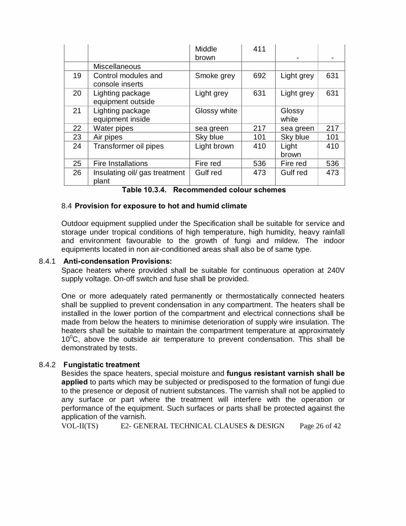
Middle brown
411 -
-
Miscellaneous 19 Control modules and
console inserts Smoke grey 692 Light grey 631
20 Lighting package equipment outside
Light grey 631 Light grey 631
21 Lighting package equipment inside
Glossy white Glossy white
22 Water pipes sea green 217 sea green 217 23 Air pipes Sky blue 101 Sky blue 101 24 Transformer oil pipes Light brown 410 Light
brown 410
25 Fire Installations Fire red 536 Fire red 536 26 Insulating oil/ gas treatment
plant Gulf red 473 Gulf red 473
Table 10.3.4. Recommended colour schemes
8.4 Provision for exposure to hot and humid climate Outdoor equipment supplied under the Specification shall be suitable for service and storage under tropical conditions of high temperature, high humidity, heavy rainfall and environment favourable to the growth of fungi and mildew. The indoor equipments located in non air-conditioned areas shall also be of same type.
8.4.1 Anti-condensation Provisions: Space heaters where provided shall be suitable for continuous operation at 240V supply voltage. On-off switch and fuse shall be provided. One or more adequately rated permanently or thermostatically connected heaters shall be supplied to prevent condensation in any compartment. The heaters shall be installed in the lower portion of the compartment and electrical connections shall be made from below the heaters to minimise deterioration of supply wire insulation. The heaters shall be suitable to maintain the compartment temperature at approximately 100C, above the outside air temperature to prevent condensation. This shall be demonstrated by tests.
8.4.2 Fungistatic treatment Besides the space heaters, special moisture and fungus resistant varnish shall be applied to parts which may be subjected or predisposed to the formation of fungi due to the presence or deposit of nutrient substances. The varnish shall not be applied to any surface or part where the treatment will interfere with the operation or performance of the equipment. Such surfaces or parts shall be protected against the application of the varnish.

VOL-II(TS) E2- GENERAL TECHNICAL CLAUSES & DESIGN Page 27 of 42
8.4.3 Ventilating specifications
In order to ensure adequate ventilation, compartments shall have ventilation openings provided with fine wire mesh of brass or galvanised steel to prevent the entry of insects and to reduce to a minimum the entry of dirt and dust. Outdoor compartment openings shall be provided with shutter type blinds.
8.4.4 Labels and plates All Equipment shall be clearly labeled indicating, where necessary, its purpose and service positions. Each phase of alternating current and each pole of direct current equipment and connections shall be coloured in an approved manner to distinguish phase or polarity. The material of all labels and the dimensions, legend, and method of printing shall be to approval. The surface of indoor labels shall have a matt or satin finish to avoid dazzle from reflected light. Colours shall be permanent and free from fading. Labels mounted on black surfaces shall have white lettering. ‘Danger’ plates shall have red lettering on a white background. All labels and plates for outdoor use shall be of non corroding material. Where the use of enameled iron plates is approved, the whole surface including the back and edges, shall be properly covered and resistant to corrosion. Protective washers of suitable material shall be provided front and back on the securing screws. Labels shall be engraved in Hindi, English and Oriya. Name plates shall be white with black engraved lettering and shall carry all the applicable information specified in the applicable items of the Standards. Any other relevant information which may be required for groups of smaller items for which this is not possible e.g. switch bays etc. a common name plate in Oriya with the title and special instructions on it shall be provided. No scratching, corrections or changes will be allowed on name plates. All equipment mounted on front and rear sides as well as equipment mounted inside the panels shall be provided with individual name plates with equipment designation engraved. On the top of each panel on front as well as rear sides large name plates with bold size lettering shall be provided for circuit/ feeder/ cubicle box designation.

VOL-II(TS) E2- GENERAL TECHNICAL CLAUSES & DESIGN Page 28 of 42
All front mounted equipment shall be also provided, at the rear, with individual name plates engraved with tag numbers corresponding to the one shown in the panel internal wiring to facilitate tracing of the wiring. The name plates shall be mounted directly by the side of the respective equipment wiring. Name plates of cubicles and panels may be made of non rusting metal or 3 ply lamicoid. These name plates may be black with white engraved lettering. The name plate inscription and size of name plates and letters shall be submitted to the Engg. Incharge for approval. The name plates of the Equipment shall include, at least, the information listed below, together with any other relevant information specified in the applicable standards:
a) Concise descriptive title of the equipment b) Rating and circuit diagrams c) Manufacturer's name, trade-mark, model type, serial number d) Instruction book number e) Year of manufacture f) Special instructions, if any, about storage, transportation, handling etc.
Each measuring instrument and meter shall be prominently marked with the quantity measured e.g. kV, A, MW etc. All relays and other devices shall be clearly marked with manufacturers name, type, serial number and electrical rating data. Danger plates and plates for phase colours shall be provided as per requirement. The Contractor shall devise a system to designate equipment and sub-systems. The nameplates/labels displaying these designations shall be installed at appropriate locations. Whenever motion or flow of fluids is involved, plates showing direction of motion or flow shall also be provided.
8.5 Padlocks For each item of plant the Contractor shall provide a padlockable handle and a non-ferrous padlock with different key changes in order to prevent access to control cabinets, cubicles and relay panels. The Contractor shall provide two keys for each lock and a master key for each substation. Cabinets for the accommodation of padlocks and keys, whilst not in use, shall be provided and shall be suitably labeled so that keys will be readily identifiable.
8.6 Earthing Metal parts of all equipment other than those forming part of an electrical circuit shall be connected directly to the main earth system via two separate conductors of adequate capacity at two different points.
VOL-II(TS) E2- GENERAL TECHNICAL CLAUSES & DESIGN Page 29 of 42
All main members of structural steelworks shall be earthed by galvanised iron flat connections bonded by welding or bolting to the steelworks. Connections to Equipment and structures shall be made clear of ground level, preferably to a vertical face and protected as appropriate against electrolytic corrosion. They shall be made between clean surfaces and of sufficient size and pressure to carry the rated short circuit current without damage. Earth bars installed directly into the ground should normally be laid bare and the trench back-filled with a fine top soil. Where the soil is of a hostile nature, special precautions must be taken to protect the earth bar, the method used being subject to the agreement of the Engg. Incharge. Joints in earth bars shall be welded and then coated with a suitable anti-corrosion protection treatment. Facilities shall be provided on the earth bar run between equipment and the base of structures, comprising a looped strip, so as to permit the attachment of portable earth connections for maintenance purposes. The cross sectional area of the earth bar and connections shall be such that the current density is not greater than 100 A/mm2 for a 3 second fault duration.
8.7 Lubrication Bearings which require lubrication either with oil or grease shall be fitted with nipples.
9.0 PRODUCTION PROCESS REQUIREMENTS
9.1 Castings 9.1.1 General
All castings shall be true to pattern, free from defects and of uniform quality and condition. The surfaces of castings which do not undergo machining, shall be free from foundry irregularities. The castings shall be subject to NDT, chemical, mechanical and metallographic tests. Details of the same shall be furnished to Engg. Incharge for review/approval. Magnetic particle inspection (MPI) test, wherever applicable, shall be carried out in longitudinal and transverse direction to detect radial and axial cracks.
9.2 Welding All welding shall be in accordance with the corresponding Indian standards.

VOL-II(TS) E2- GENERAL TECHNICAL CLAUSES & DESIGN Page 30 of 42
10.0 WIRING, CABLING AND CABLE INSTALLATION
10.1 Cubicle wiring Panels shall be complete with interconnecting wiring between all electrical devices in the panels. External connections shall be achieved through terminal blocks. Where panels are required to be located adjacent to each other all inter panel wiring and connections between the panels shall be carried out internally. The Contractor shall furnish a detailed drawing of such inter panel wiring. The Contractor shall ensure the completeness and correctness of the internal wiring and the proper functioning of the connected equipment. All wiring shall be carried out with 1.1 kV grade, PVC insulated, single core, stranded copper wires. The PVC shall have oxygen index not less than ‘29’ and Temperature index not less than 250C. The wires shall have annealed copper conductors of adequate size comprise not less than three strands The minimum cross sectional area of the stranded copper conductor used for internal wiring shall be as follows:
a) All circuits excepting CT circuits and energy metering circuit of VT 2.5 sq.mm b) All CT circuits and metering circuit of VT 2.5 sq. mm
All internal wiring shall be supported, neatly arranged, readily accessible and connected to equipment terminals and terminal blocks. Wiring gutters and troughs shall be used for this purpose. Cubicle connections shall be insulated with PVC to IEC 227. Wires shall not be jointed or teed between terminal points. Bus wires shall be fully insulated and run separately from one another. Auxiliary bus wiring for AC and DC supplies, voltage transformer circuits, annunciation circuits and other common services shall be provided near the top of the panels running throughout the entire length of the panel suite. Longitudinal troughs extending throughout the full length of panel shall be preferred for inter panel wiring. All inter connecting wires between adjacent panels shall be brought to a separate set of terminal blocks located near the slots of holes meant for the passage of the inter connecting wires. Interconnection of adjacent panels on site shall be straightforward and simple. The bus wires for this purpose shall be bunched properly inside each panel. Wire termination shall be made with solder less crimping type and tinned copper lugs which firmly grip the conductor. Insulated sleeves shall be provided at all the wire terminations. Engraved core identification plastic ferrules marked to correspond with panel wiring diagram shall be fitted at both ends of each wire. Ferrules shall fit tightly on the wire and shall not fall off when the wire is disconnected from terminal blocks.
VOL-II(TS) E2- GENERAL TECHNICAL CLAUSES & DESIGN Page 31 of 42
Numbers 6 and 9 shall not be included for ferrules purposes unless the ferrules have numbers underscored to enable differentiation. (i.e. 6 and 9). Fuses and links shall be provided to enable all circuits in a cubicle, except a lighting circuit, to be isolated from the bus wires. The DC trip and AC voltage supplies and wiring to main protective gear shall be segregated from those for back-up protection and also from protective Equipment for special purposes. Each such group shall be fed through separate fuses from the bus wires. There shall not be more than one set of supplies to the Equipment comprising each group. All wires associated with the tripping circuits shall be provided with red ferrules marked “Trip”. It shall be possible to work on small wiring for maintenance or test purposes without making a switchboard dead. The insulation material shall be suitably coloured in order to distinguish between the relevant phases of the circuit. When connections rated at 380 volt and above are taken through junction boxes they shall be adequately screened and “DANGER” notices shall be affixed to the outsides of junction boxes or marshalling kiosk. Where connections to other equipment and supervisory equipment are required the connections shall be grouped together.
10.2 LV power cabling LVAC cable terminals shall be provided with adequately sized, hot pressed, cast or crimp type lugs. Where sweating sockets are provided they shall be without additional clamping or pinch bolts. Where crimp type lugs are provided they shall be applied with the correct tool and the crimping tool shall be checked regularly for correct calibration. Bi-metallic joints between the terminals and lugs shall be provided where necessary. Terminals shall be marked with the phase colour in a clear and permanent manner. A removable gland plate shall be provided by the Contractor. The Contractor shall be responsible for drilling the cable gland plate. Armoured cables shall be provided with suitable glands for terminating the cable armour and shall be provided with an earthing ring and lug to facilitate connection of the gland to the earth bar.
10.3 Multi-core cables and conduit wiring External multi-core cabling between items of main and ancillary equipment shall form part of the Contract Works and shall consist of un-armoured multi-core cable with stranded copper conductors PVC insulated and PVC over sheathed complying with the requirements of IEC 227 and 228 as applicable. Multi-core cable for instrumentation and control purposes shall be supplied with 2.5 mm2 stranded copper cores. Multi-core cables for CT and VT circuits shall be supplied with two by 2.5 mm2 stranded copper cores and the cores shall be identified by the phase colour.

VOL-II(TS) E2- GENERAL TECHNICAL CLAUSES & DESIGN Page 32 of 42
Where conduit is used the runs shall be laid with suitable falls and the lowest parts of the run shall be external to the equipment. All conduit runs shall be adequately drained and ventilated. Conduits shall not be run at or below ground level. Multi-core cable tails shall be so bound that each wire may be traced to its cable without difficulty. All multi-core cables shall be provided with 20 % spare cores and the spare cores shall be numbered and terminated at a terminal block in the cubicle. Where cables are terminated in a junction box and the connections to a relay or control cubicle are continued in conduit, the spare cores shall be taken through the conduit and terminated in the cubicle. The dc trip and ac voltage circuits shall be segregated from each other as shall the circuits to main protective gear be segregated from those for back-up protection. The screens of screened pairs of multi-core cables shall be earthed at one end of the cable only. The position of the earthing connections shall be shown clearly on the diagram. All wires on panels and all multi-core cable cores shall be crimped with the correct size of crimp and crimping tool and will have ferrules which bear the same number at both ends. At those points of interconnection between the wiring carried out by separate contractors where a change of number cannot be avoided double ferrules shall be provided on each wire. The change of numbering shall be shown on the appropriate diagram of the equipment. The same ferrule number shall not be used on wires in different circuits on the same panels. The Contractor shall provide a two (2) metre loop of spare cable at both ends of all multi-core cable runs and shall leave sufficient lengths of tails at each end of the multi-core cables to connect up to the terminal boards. The Contractor shall also strip, insulate, ring through and tag the tails and shall also seal the cable boxes. The Contractor shall be responsible for re-checking the individual cores and for the final connecting up and fitting of numbered ferrules within all equipment provided on this contract. The drilling of gland plates, supply and fitting of compression glands and connecting up of power cables included in the Contract scope of work shall be carried out under this contract.
10.4 Laying and installing of cables 10.4.1 General
For cable laying the following shall apply: c) Switchyard area - In concrete cable troughs (cable trench having cable racks with
cable ` trays) d) Control Room - On cable racks consisting of slotted type and ladder type cable trays e) Buildings - Conduits Directly buried cables shall be used wherever necessary with
the approval of Engg. Incharge.

VOL-II(TS) E2- GENERAL TECHNICAL CLAUSES & DESIGN Page 33 of 42
10.4.2 Laying of cable Cables shall be laid in concrete troughs provided under this contract or drawn into pipes or ducts or on cable racks or directly buried as may be required by the Engg. Incharge. Concrete troughs shall be designed so that the cables are supported on cable support systems and the supports shall be arranged so as to allow the segregation of power, control (including CT and VT circuits) and communications cables onto different layers of cable supports. All cable supports shall be earthed in accordance with IS 3043. The minimum vertical separation between layers of cable tray shall be not less than 300 mm. The cable support system shall be designed and constructed to carry the required cables without undue crowding of the supports and without overloading the supports. The maximum number of layers of cable that shall be permitted on a single cable support shall be three. The width of the cable supports shall be selected to ensure that the supports are not crowded, the cable supports are not overloaded and that sufficient space is provided in the cable trough to allow for personnel access during and after cable installation. The width of cable supports should not exceed 750 mm. Cables shall be laid direct in the ground only at the discretion of the Engg. Incharge. All cables laid direct in the ground outside buildings shall be laid in a trench and protected by reinforced concrete slabs or cable tiles. For auxiliary cables the top of the slab or tile shall be at a depth not less than 300 mm below the surface of the ground and there shall be a layer of fine well packed riddled earth 75 mm thick in between the cable and the bottom of the trench and between the top of the cable and the underside of the slab. The Contractor shall be responsible for the proper laying of all cables in the ground. Where cables in the same trench are laid over each other, they shall be separated by not less than 75 mm of riddled earth. The riddled earth used for this purpose shall have been passed through a screen having a 12 mm square mesh. Where cables pass under roadways they shall be laid in pipes at a depth not less than 800 mm below the surface. The Contractor shall be responsible for the excavation of trenches which shall include all pumping and baling required and the provision of all necessary labour, plant, tools, water, additional soil, fuel or motor power for such purposes. Cables in trenches will be inspected by the Engg. Incharge before the trenches are backfilled. The running of communications and power cables along the same route shall be avoided as far as possible. Where this is not possible they shall be segregated, the one group from the other. Power and communication cables shall be laid in separate tiers. For other than directly buried cables the order of laying of various cables shall be as follows:
f) Power cables on top tiers. g) Control/ instrumentation and other service cables in bottom tiers.
VOL-II(TS) E2- GENERAL TECHNICAL CLAUSES & DESIGN Page 34 of 42
10.4.3 Cable tags and markers Each cable and conduit run shall be tagged with numbers that appear in the cable and conduit schedule. The tag shall be of aluminium with the number punched on it and securely attached to the cable conduit by not less than two turns of 20 SWG GI wire conforming to IS 280. Cable tags shall be of rectangular shape for power cables and of circular shape for control cables. Location of cables laid directly in the ground shall be clearly indicated with cable marker made of galvanised iron plate. Location of buried cable joints shall be indicated with a cable marker having an additional inscription "Cable joint". Cable markers shall project 150 mm above ground and shall be spaced at an interval of 30 meters and at every change in direction. They shall be located on both sides of road and drain crossings. Cable tags shall be provided on all cables at each end (just before entering the equipment enclosure), on both sides of a wall or floor crossing, on each duct, conduit entry and at every twenty meters (20 m) in cable tray/trench runs. Cable tags shall be provided inside switchgear, motor control centres, control and relay panels etc.. and wherever required for cable identification when a number of cables enter together through a gland plate. The price of cable tags and markers shall be included in the installation rates for cables/conduits quoted by the Bidder.
10.4.4 Cable supports and cable tray mounting arrangements in control room The control room will normally be provided with embedded steel inserts on concrete floors/walls for the purpose of cabling in the control room. The supports shall be secured by welding to these inserts or available building steel structures. However, in cases where no such embedded steel inserts are available, the same shall have to secured to the supports on walls or floors by suitable anchoring .
10.4.5 Cable support structure in switchyard cable trenches The contractor shall fabricate and install cable support structures in cable trenches. These supports shall be provided at 750 mm spacing along the run of cable trenches. Cable supports and cable racks shall be fabricated from standard structural steel members, channels, angles and flats of required size. The fabrication, welding and erection of these structures shall conform to the relevant clauses of this Specification, in addition to the specification given herein.
10.5 Termination of cables and wires Where cables leave the Equipment in an upward direction the cable boxes shall be provided with a barrier joint to prevent leakage of cable oil or compound into the Equipment. Where cable cores are liable to contact with oil or oil vapour the insulation shall be unaffected by oil.

VOL-II(TS) E2- GENERAL TECHNICAL CLAUSES & DESIGN Page 35 of 42
PVC sheathed cables shall be terminated by compression glands complying with BS 6121 (or equivalent). Auxiliary PVC insulated cables shall be terminated with compression type glands, clamps or armour clamps complete with all the necessary fittings. Colours shall be marked on the cable box, cable tail ends and single core cables at all connecting points and/or any positions the Engg. Incharge may determine. Cable boxes shall be provided with suitable labels indicating the purpose of the supply where such supply is not obvious or where the Engg. Incharge may determine. All cables shall be identified and shall have phase colours marked at their termination. All incoming and outgoing connections shall be terminated at a terminal block. Direct termination into auxiliary switches will not be accepted.
10.6 DEGREES OF PROTECTION Degrees of protection shall be provided in accordance with IEC 144 and IEC 529 and be as follows:
h) For outdoor applications, IP 55. i) For indoor applications where purpose built accommodation is provided, e.g. switch
and control and relay rooms in auxiliary plant buildings, IP 41. j) Where dust can adversely affect equipment within the enclosure, this equipment
should be separately housed with a degree of protection of IP 51. k) For indoor applications where the equipment is housed in the same building as that
enclosing water and steam operated equipment, the degrees of protection stated in the previous paragraph shall be up-rated to IP 44 and IP 54 respectively. Where more severe environments exist, e.g. steam and oil vapour or other deleterious chemical environments, special measures will be necessary and the degree of protection required will be specified separately. The Contractor shall submit a schedule for providing the degree protection to various control boxes, junction boxes etc. for the Engg. In charge’s approval.
10.6 SUPPLY VOLTAGE All incoming supplies of greater than 125 V to earth shall have their termination shrouded by a suitable insulating material. The auxiliary supply voltages on site shall be as follows:
Nominal Voltage V
Variation Frequency Hz or DC
Phase Wires Neutral Connection
430 10% 505% 3 4 Solidly earthed
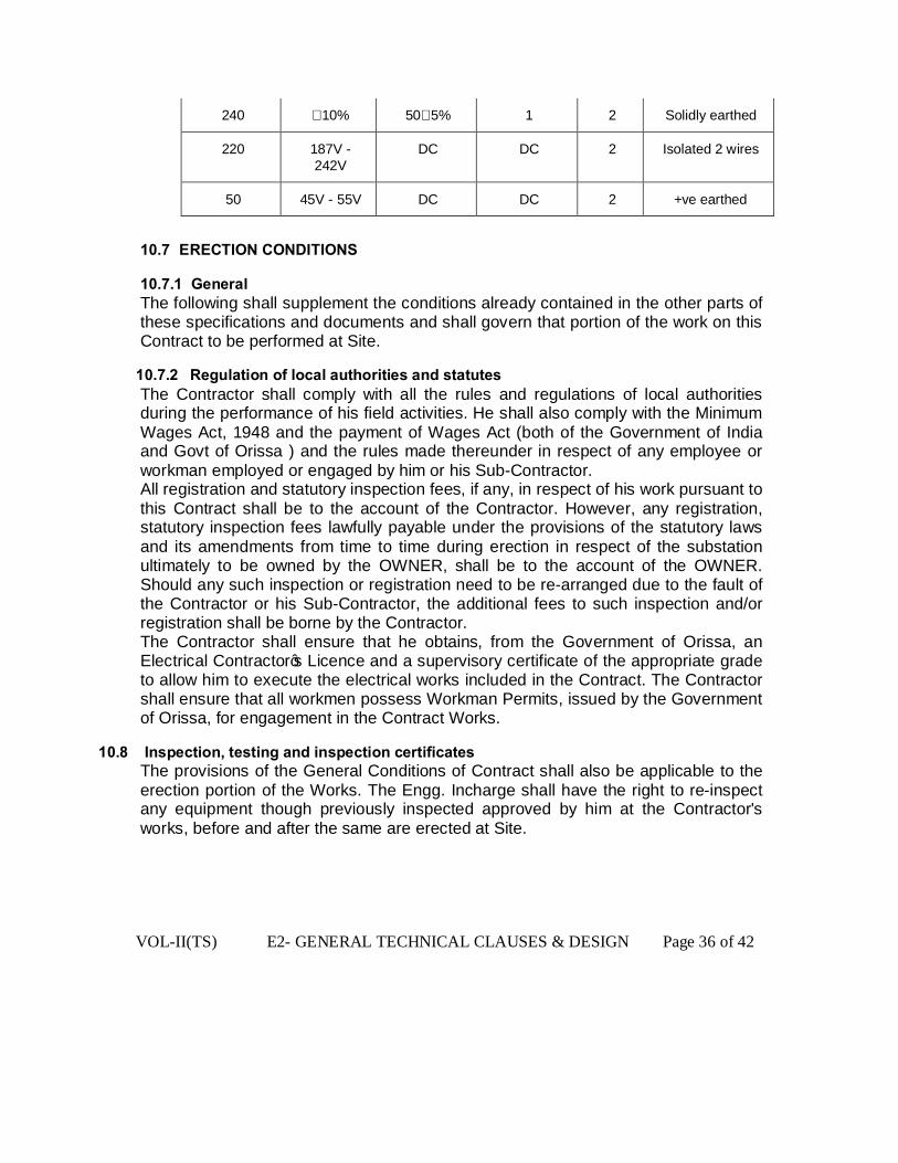
VOL-II(TS) E2- GENERAL TECHNICAL CLAUSES & DESIGN Page 36 of 42
240 10% 505% 1 2 Solidly earthed
220 187V - 242V
DC DC 2 Isolated 2 wires
50 45V - 55V DC DC 2 +ve earthed
10.7 ERECTION CONDITIONS
10.7.1 General The following shall supplement the conditions already contained in the other parts of these specifications and documents and shall govern that portion of the work on this Contract to be performed at Site.
10.7.2 Regulation of local authorities and statutes The Contractor shall comply with all the rules and regulations of local authorities during the performance of his field activities. He shall also comply with the Minimum Wages Act, 1948 and the payment of Wages Act (both of the Government of India and Govt of Orissa ) and the rules made thereunder in respect of any employee or workman employed or engaged by him or his Sub-Contractor. All registration and statutory inspection fees, if any, in respect of his work pursuant to this Contract shall be to the account of the Contractor. However, any registration, statutory inspection fees lawfully payable under the provisions of the statutory laws and its amendments from time to time during erection in respect of the substation ultimately to be owned by the OWNER, shall be to the account of the OWNER. Should any such inspection or registration need to be re-arranged due to the fault of the Contractor or his Sub-Contractor, the additional fees to such inspection and/or registration shall be borne by the Contractor. The Contractor shall ensure that he obtains, from the Government of Orissa, an Electrical Contractor’s Licence and a supervisory certificate of the appropriate grade to allow him to execute the electrical works included in the Contract. The Contractor shall ensure that all workmen possess Workman Permits, issued by the Government of Orissa, for engagement in the Contract Works.
10.8 Inspection, testing and inspection certificates The provisions of the General Conditions of Contract shall also be applicable to the erection portion of the Works. The Engg. Incharge shall have the right to re-inspect any equipment though previously inspected approved by him at the Contractor's works, before and after the same are erected at Site.
VOL-II(TS) E2- GENERAL TECHNICAL CLAUSES & DESIGN Page 37 of 42
10.9 Contractor's field operation 10.9.1 General The Contractor shall inform the Engg. Incharge in advance of field activity plans and schedules for carrying-out each part of the works. Any review of such plans or schedules or methods of work by the Engg. Incharge shall not relieve the Contractor of any of his responsibilities towards the field activities. Such reviews shall not be considered as an assumption of any risk or liability by the OWNER or any of his representatives, and no claim of the Contractor will be entertained because of the failure or inefficiency of any such plan or schedule or method of work reviewed. The Contractor shall be solely responsible for the safety, adequacy and efficiency of plant and equipment and his erection methods.
10.9.2 Progress Report Progress reports shall be provided by the Contractor to the Engg. Incharge in accordance with the relevant parts of this specification. Appropriate photographs shall accompany the monthly progress reports.
10.10 Facilities to be provided by the contractor 10.10.1 Unloading
Contractor shall make his own arrangement for unloading the equipment at site. 10.10.2 Tools, tackle and scaffoldings
The Contractor shall provide all the construction equipment tools, tackle and scaffoldings required for offloading, storage, pre-assembly, erection, testing and commissioning of the equipment covered under the Contract. He shall submit a list of all such materials to the Engg. Incharge before the commencement of pre-assembly at Site. These tools and tackles shall not be removed from the Site without the written permission of the Engg. Incharge.
10.11 First-Aid and general hygiene The Contractor shall provide necessary first-aid facilities for all his employees, representatives and workmen working at the site. At all times at least ten percent of all Contractors personnel assigned to the worksite shall be shall be trained in administering first-aid. The labour colony, offices and residential areas of the Contractor’s employees and workmen shall be kept clean and neat to the entire satisfaction of the Engg. Incharge. Proper sanitary arrangements shall be provided by the Contractor in work-areas, offices and residential areas of the Contractor. Waste oil shall be disposed of in a manner acceptable to the Engg. Incharge . Under no circumstances shall waste oil be dumped into uncontrolled drains.
10.12 Security The Contractor shall have total responsibility for all equipment and material in his custody, stored, loose, semi-assembled and/or erected by him at Site. The Contractor shall make suitable security arrangements including employment of
VOL-II(TS) E2- GENERAL TECHNICAL CLAUSES & DESIGN Page 38 of 42
security personnel to ensure the protection of all materials, equipment and works from theft, fire, pilferage and any other damages and loss.
10.13 Materials handling and storage All the equipment furnished under the Contract and arriving at Site shall be promptly received, unloaded and transported and stored in the stores by the Contractor. Contractor shall be responsible for examining the complete shipment and notifying the Engg. Incharge immediately of any damage, shortage, discrepancy etc. for the purpose of Engg. In charge’s information only. The Contractor shall submit to the Engg. Incharge every week a report detailing all the receipts during the weeks. However, the Contractor shall be solely responsible for any shortages or damages during transit, handling, storage and erection of the equipment at Site. Any demurrage, wharfage and other such charges claimed by the transporters, railways etc. shall be to the account of the Contractor. The Contractor shall maintain an accurate and exhaustive record detailing all equipment received by him for the purpose of erection and keep such record open for the inspection of the Engg. Incharge. All equipment shall be handled carefully to prevent any damage or loss. All equipment stored shall be properly protected to prevent damage. Equipment from the store shall be moved to the actual location at an appropriate time so as to avoid damage of such equipment at Site. All the materials stored in the open or dusty location shall be covered with suitable weather-proof and flameproof covering material. The Contractor shall be responsible for making suitable indoor facilities for the storage of all equipment which requires to be kept indoors.
11.0 CONSTRUCTION MANAGEMENT
11.1 General Time is the essence of the Contract and the Contractor shall be responsible for performance of his Works in accordance with the specified construction schedule. If at any time the Contractor is falling behind the schedule, he shall take necessary action to make good for such delays by increasing his work force or by working overtime to accelerate the progress of the work and to comply with schedule and shall communicate such actions in writing to the Engg. Incharge, providing evidence that his action will compensate for the delay. The Contractor shall not be allowed any extra compensation for such action.
11.2 Field office records The Contractor shall maintain at his Site office up-to-date copies of all drawings, specifications and other supplementary data complete with all the latest revisions thereto. The Contractor shall also maintain in addition the continuous record of all changes to the above contract documents, drawings, specifications, supplementary data, etc. effected at the field. On completion of his total assignment under the
VOL-II(TS) E2- GENERAL TECHNICAL CLAUSES & DESIGN Page 39 of 42
Contract, such drawings and engineering data shall be submitted to the Engg. Incharge in the required number of copies.
11.2 Protection of property and Contractor's liability The Contractor will ensure provision of necessary safety equipment such as barriers, sign-boards, warning light and alarms, personal protective equipment etc. to provide adequate protection to persons and property. The Contractor shall be responsible for giving reasonable notice to the Engg. Incharge and the owners of public or private property and utilities when such property and utilities are likely to be damaged or injured during the performance of his works, and shall make all necessary arrangements with such owners, related to removal and/or replacement or protection of such property and utilities.
12.0 CODE REQUIREMENTS The erection requirements and procedures to be followed during the installation of the equipment shall be in accordance with the relevant Indian/International Standards/Regulations, ASME codes, accepted good engineering practice, drawings and other applicable Indian codes and laws and regulations.
13.0 OWNER'S SUPERVISION To eliminate delays and avoid disputes and litigation, it is agreed between the Parties to the Contracts that all matters and questions shall be referred to the OWNER and without prejudice the Contractor shall proceed to comply with the OWNER's decision. The work shall be performed under the direction and supervision of the Engg. Incharge. The scope of the duties of the Engg. Incharge, pursuant to the contract, will include but not be limited to the following:
l) Interpretation of all the terms and conditions of these documents and specifications. m) Review and interpretation of all the Contractors drawing, engineering data etc. n) Witness or authorise his representative to witness tests and trials either at the
manufacturer's works or at site, or at any place where work is performed under the Contract.
o) Inspect, accept or reject any equipment, material and work under Contract. p) Issue certificate of acceptance and/or progressive payment and final payment
certificates. q) Review and suggest modification and improvements in completion schedules from
time to time. r) Supervise the Quality Assurance program implementation at all stages of the Works.

VOL-II(TS) E2- GENERAL TECHNICAL CLAUSES & DESIGN Page 40 of 42
14.0 TESTING AND INSPECTION The Contractor shall carry out the tests stated in accordance with the conditions of this Specification, without extra charge for such additional tests as in the opinion of the Engg. Incharge are necessary to determine that the Contract Works comply with this Specification. The tests shall be carried out generally in accordance with the relevant IEC’s or IS or equivalent standards. The specific details of testing and inspection are given in the appropriate section of this Specification. The Contractor shall submit Type Test Reports for all equipment being supplied by him for the Engg. Incharge’s approval. The Engg. Incharge may also give instruction to carry out Type Tests, routine tests or acceptance tests. Type Test Charges shall be paid as per the rates indicated in the Price Schedules. All materials used shall be subjected to such routine tests as are customary in the manufacture of the types of plant included in the Contract Works. These materials shall withstand satisfactorily all such tests. All tests shall be carried out to the satisfaction of the Engg. Incharge, in his presence, at such reasonable times as he may require, unless agreed otherwise. Not less than three weeks notice of all tests shall be given to the Engg. Incharge in order that he may be represented if he so desires. As many tests as possible shall be arranged together. Six copies of the Contractor’s test reports and test sheets shall be supplied to the Engg. Incharge for approval. Measuring Equipment shall be approved by the Engg. Incharge and if required shall be calibrated at the expense of the Contractor at an approved laboratory. The Contractor shall be responsible for the proper testing of the work completed or plant or materials supplied by a sub-contractor to the same extent as if the work, plant or materials were completed or supplied by the Contractor himself. All Equipment, instruments and connections required for the above tests shall be provided by the Contractor, but the Engg. Incharge may permit the use for the tests on site, any instruments and Equipment which may be provided permanently on site as part of the contract works conditional upon the Contractor accepting liability for any damage which may be sustained by such equipment during the test. The contractor shall supply suitable test pieces of all materials as required by the Engg. Incharge. If required by the Engg. Incharge, test specimens shall be prepared for check testing and forwarded at the expense of the Contractor to an independent testing authority selected by the Engg. Incharge. Any costs incurred by the OWNER in connection with inspection and re-testing as a result of a failure of the subject under test, or damage during transport, or erection on site before take-over by the OWNER, shall be to the account of the Contractor. No inspection or lack of inspection or passing by the Engg. Incharge of work, plant or materials, whether carried out or supplied by the Contractor or sub-contractor, shall relieve the Contractor from his liability to complete the Contract Works in accordance with the Contract or exonerate him from any of his guarantees.

VOL-II(TS) E2- GENERAL TECHNICAL CLAUSES & DESIGN Page 41 of 42
15.0 0 FIRE PRECAUTIONS All Equipment, connections and cabling shall be designed and arranged to minimise the risk of fire and any damage which might be caused in the event of fire. When cabling is carried out as part of this Contract the Contractor shall be responsible for sealing all holes in floors, walls, roofs etc. through which the cabling may pass. The work procedures that are to be used during the erection shall be those which minimise fire hazards to the maximum extent practicable. Combustible materials, combustible waste and rubbish shall be collected and removed from the site at least once each day. Fuels, oils and volatile or flammable materials shall be stored away from the construction site and equipment and material stores in appropriate safe containers. All Contractor’s supervisory personnel and at least ten percent all of workers shall be trained for fire-fighting and shall be assigned specific fire protection duties. At least ten percent of all personnel assigned to site at any one time shall be trained for fire fighting. The contractor shall provide sufficient fire protection equipment of the types and sizes for the ware-houses, office temporary structures, labour colony area etc. Access to such fire protection equipment shall be easy and kept open at all time.
16.0 SPANNERS AND SPECIAL TOOLS A complete set of spanners shall be supplied for each station to fit every nut and bolt head on the Equipment supplied under this Contract, together with all special tools required for the adjustment and maintenance of the equipment. These tools shall be mounted in a lockable cabinet at each substation, also to be provided under this Contract. Eye bolts which have to be removed after use shall be accommodated in the cabinets. Spanners and other maintenance equipment provided under the Contract shall not be used for the purpose of erection of the contract Works. Any special devices, slings or tackle necessary for the complete overhaul of the plant shall be handed over to the Engg. Incharge in working order on completion of the Contract. On delivering any or all of these tools to the Engg. Incharge, a signature shall be obtained from the Engg. Incharge’s representative. Any tools not signed for shall be deemed not to have been delivered.
17.0 RUNWAY BEAMS, EYE BOLTS AND LIFTING TACKLE Runway beams shall comply with the requirements of BS 2853, or its equivalent, and shall be tested after erection in accordance with this standard and this Specification. The Contractor shall be responsible for the provision of the appropriate test certificates which must be in accordance with Appendix C of BS 2853. All slings, eye bolts and other lifting tackle provided shall be proof tested to twice the safe working load and suitably marked with embossed labels to show clearly the safe working loads.

VOL-II(TS) E2- GENERAL TECHNICAL CLAUSES & DESIGN Page 42 of 42
VOL-II(TS) E3-SYSTEM & CLIMATIC CONDITIONS Page 1 of 4
TECHNICAL SPECIFICATION FOR
SYSTEM & CLIMATIC CONDITIONS
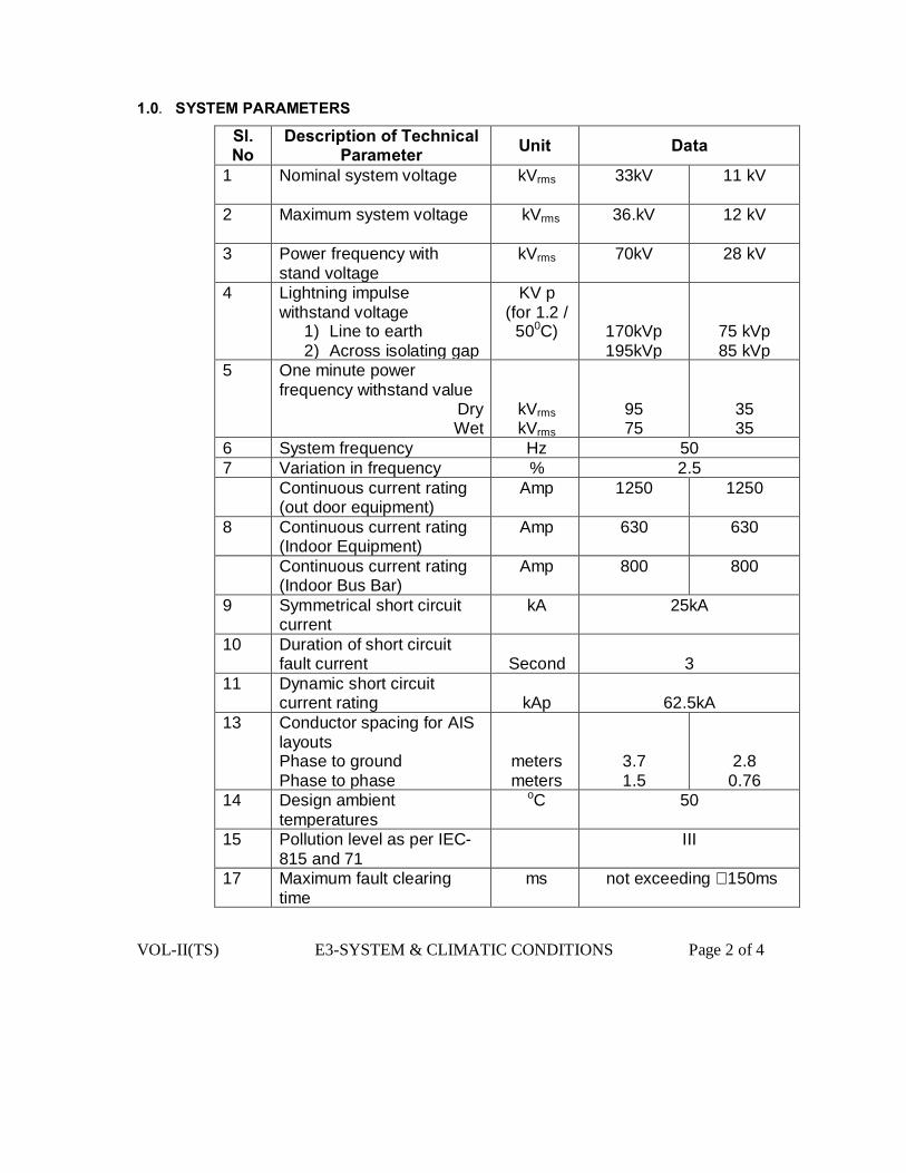
VOL-II(TS) E3-SYSTEM & CLIMATIC CONDITIONS Page 2 of 4
1.0. SYSTEM PARAMETERS
Sl. No
Description of Technical Parameter Unit Data
1 Nominal system voltage kVrms
33kV 11 kV
2 Maximum system voltage kVrms
36.kV 12 kV
3 Power frequency with stand voltage
kVrms
70kV 28 kV
4 Lightning impulse withstand voltage
1) Line to earth 2) Across isolating gap
KV p (for 1.2 /
500C)
170kVp 195kVp
75 kVp 85 kVp
5 One minute power frequency withstand value
Dry Wet
kVrms kVrms
95 75
35 35
6 System frequency Hz 50 7 Variation in frequency % 2.5 Continuous current rating
(out door equipment) Amp 1250 1250
8 Continuous current rating (Indoor Equipment)
Amp 630 630
Continuous current rating (Indoor Bus Bar)
Amp 800 800
9 Symmetrical short circuit current
kA 25kA
10 Duration of short circuit fault current
Second
3
11 Dynamic short circuit current rating
kAp
62.5kA
13 Conductor spacing for AIS layouts Phase to ground Phase to phase
meters meters
3.7 1.5
2.8 0.76
14 Design ambient temperatures
oC 50
15 Pollution level as per IEC-815 and 71
III
17 Maximum fault clearing time
ms not exceeding 150ms

VOL-II(TS) E3-SYSTEM & CLIMATIC CONDITIONS Page 3 of 4
18 Safety clearances 1. Section clearance a) Ground clearances(
between ground and bottom most part of energised object)
b) Horizontal clearance between the fence and energised object
c) Horizontal clearance between the road centre line and energised part of the nearby equipment
metres
metres
metres
metres
4 4
As per I.E. Rules
As per I.E.
Rules
3 3
As per I.E. Rules
As per I.E.
Rules
19 Bay width metres 5.5 4.0 20 Height of bus equipment
interconnection from ground
metres 4 3.5
21 Height of strung busbar metres 5.5 4.0
2.0 CLIMATIC CONDITIONS
The service conditions shall be as follows:
1.Maximum altitude above sea level 1,000m
2.Maximum ambient air temperature 50°C
3. Maximum daily average ambient air temperature 35°C
4.minimum ambient air temperature 0°C
5.maximum temperature attainable by an object exposed to the sun 60°C
6.maximum yearly weighted average ambient temperature 32°C
7.maximum relative humidity 100%
8.average number of thunderstorm days per annum (isokeraunic level) 70
9.average number of rainy days per annum 120
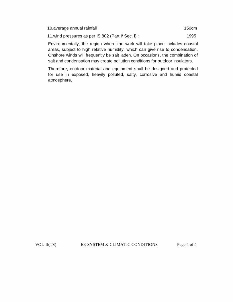
VOL-II(TS) E3-SYSTEM & CLIMATIC CONDITIONS Page 4 of 4
10.average annual rainfall 150cm
11.wind pressures as per IS 802 (Part I/ Sec. l) : 1995
Environmentally, the region where the work will take place includes coastal areas, subject to high relative humidity, which can give rise to condensation. Onshore winds will frequently be salt laden. On occasions, the combination of salt and condensation may create pollution conditions for outdoor insulators.
Therefore, outdoor material and equipment shall be designed and protected for use in exposed, heavily polluted, salty, corrosive and humid coastal atmosphere.

VOL-II(TS) E4- SWITCHGEAR AIS/GIS/CONTAINISER Page 1 of 58
SWITCHGEAR FOR GIS/AIS TECHNICAL SPECIFICATION
For
PART – A 33 KV Indoor Switcgear panel for GIS and AIS .
PART – B 11 KV Indoor Switcgear panel for AIS
PART – C CONTAINSER SUB STATION
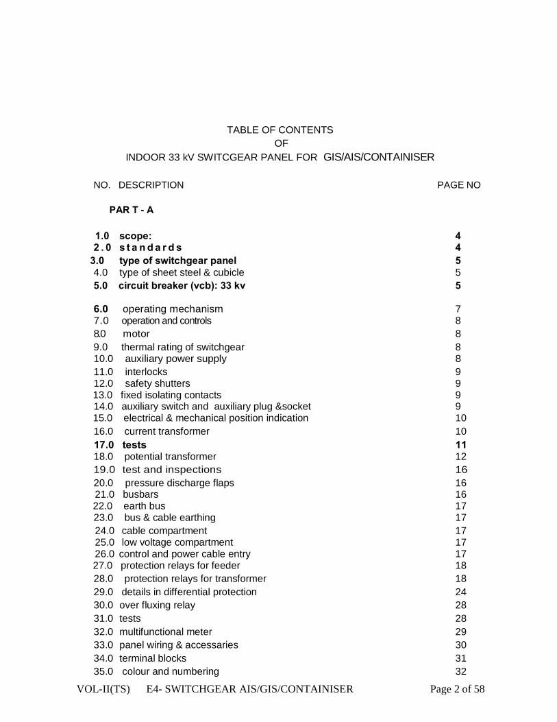
VOL-II(TS) E4- SWITCHGEAR AIS/GIS/CONTAINISER Page 2 of 58
TABLE OF CONTENTS OF
INDOOR 33 kV SWITCGEAR PANEL FOR GIS/AIS/CONTAINISER
NO. DESCRIPTION PAGE NO PAR T - A
1.0 scope: 4 2 . 0 s t a n d a r d s 4
3.0 type of switchgear panel 5 4.0 type of sheet steel & cubicle 5 5.0 circuit breaker (vcb): 33 kv 5
6.0 operating mechanism 7 7.0 operation and controls 8 8.0 motor 8 9.0 thermal rating of switchgear 8 10.0 auxiliary power supply 8 11.0 interlocks 9 12.0 safety shutters 9
13.0 fixed isolating contacts 9 14.0 auxiliary switch and auxiliary plug &socket 9
15.0 electrical & mechanical position indication 10 16.0 current transformer 10
17.0 tests 11 18.0 potential transformer 12 19.0 test and inspections 16 20.0 pressure discharge flaps 16 21.0 busbars 16
22.0 earth bus 17 23.0 bus & cable earthing 17 24.0 cable compartment 17 25.0 low voltage compartment 17 26.0 control and power cable entry 17
27.0 protection relays for feeder 18 28.0 protection relays for transformer 18 29.0 details in differential protection 24 30.0 over fluxing relay 28 31.0 tests 28 32.0 multifunctional meter 29 33.0 panel wiring & accessaries 30 34.0 terminal blocks 31 35.0 colour and numbering 32

VOL-II(TS) E4- SWITCHGEAR AIS/GIS/CONTAINISER Page 3 of 58
36.0 circuit diagram 32 37.0 disconnectors 32 38.0 auxiliary supply 32 39.0 overall dimention 32 40.0 type test of the 33 kv switch gear (vcb) panel 32 41.0 qualifying requirement 33
INDOOR SWITCGEAR PANEL FOR GIS/AIS
NO. DESCRIPTION PAGE NO PAR T - B 1.0 Requirements 35 2.0 Standards 35 3.0 Basic Technical Requirements 36 4.0 System Conditions 37 5.0 11kV VCB 37 6.0 Interrupting Media(Vaccum) 38 7.0 Auxilliary Contacts 38 8.0 Indications 38 9.0 Operation & Control 38 10.0 Current Transformer 39 11.0 Fitting & Accessories of CT 41 12.0 Test 42 13.0 Potential Transformer 42 14.0 Fitting & Accessories of PT 45 15.0 Fuse Protection 45 16.0 Circuit Diagram 45 17.0 Termination 45 18.0 Earthing Terminal 46 19.0 Test & Inspection 46 20.0 Protective Relay & Control Pannel 47 21.0 Multifunctional Meter 47 22.0 Panel Wiring & Accessories 48 23.0 Terminal Blocks 49 24.0 Colour & Numbering 49 25.0 Circuit Diagram 50 26.0 Operating Mechanism 50 27.0 Tests 52 28.0 Performance Requirement 54 29.0 Earthing 54 30.0 Mandatory Spare Parts 55

VOL-II(TS) E4- SWITCHGEAR AIS/GIS/CONTAINISER Page 4 of 58
PART -A
1.0 SCOPE:
This specification covers design, engineering, manufacture, testing, and inspection of 33 KV indoor Switchgear panel (provided with Vacuum circuit Breaker, CT, IVT, Disconnector etc) for use in the 33/11KV primary substations under the distribution networks. 33 KV Switchgear (Vacuum breakers,CT,IVT & Disconnector) must be type tested & the Dimension of Type Tested equipment are only be accepted. 1.1 Description of the switchgear panels for GIS & AIS.
Indoor switchgears for GIS/AIS should be provided in a cubicle, which shall be erected inside a building. Separate switchgear panels for 33 KV GIS & AIS and 11 KV AIS system to be considered. Care should be taken during manufacturing of the same as the equipment like VCB, Disconnector switches, CT & IVT are to be installed in the panel individually. Vibration is inevitable as mechanical operation for closing the VCB & disconnectors may cause problem and its performance will be affected. In 33 KV GIS panel SF6 gas will be filled as insulation at 0.3 bar relative pressure to ensure insulation and breaking operation. Sealed for life,the enclosure shall meet the “sealed pressure system” criterion in accordance with the IEC 62271-1. The manufacturer shall confirm that the maximum leakage rate is lower than 0.1% per year. 2 . 0 S T A N D A R D S : Expect where modified by this specification, the circuit breakers and the accessories shall be designed, manufactured and tested in accordance with latest editions of the following standards.
IEC/ISO/BS IS Subject IEC:56 IEC:62271-100 & 200
High voltage alternating current circuit breakersgeneral Requirement.
IEC:694 IS : 12729 Common clauses of high voltage switch-gear and control gear standards (for voltage exceeding 1000 V).
IEC:60 IS : 9135 High Voltage testing techniques. I EC:427 IS:13516 Method of synthetic testing of HV .A.0 circuit breakers. IEC: 1233 HV. AC. Circuit breakers- inductive load switching. IEC: 17A/CD:474 HV. AC. Circuit breakers- capacitive switching. IEC:529 IS: 13947 Degree of protection provided by enclosure. IEC:137 IS: 2099 Insulating bushing for A.C. voltages above 1000V IEC:233 IS : 5621 Hollow insulators for use in electrical equipment & IEC:273 IS: 5350 Characteristics of indoor and outdoor post insulators
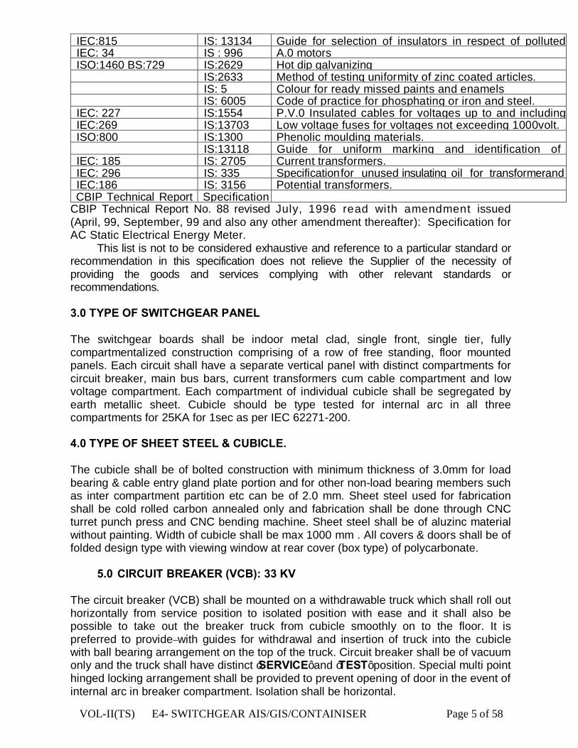
VOL-II(TS) E4- SWITCHGEAR AIS/GIS/CONTAINISER Page 5 of 58
IEC:815 IS: 13134 Guide for selection of insulators in respect of polluted IEC: 34 IS : 996 A.0 motors ISO:1460 BS:729 IS:2629 Hot dip galvanizing
IS:2633 Method of testing uniformity of zinc coated articles. IS: 5 Colour for ready missed paints and enamels IS: 6005 Code of practice for phosphating or iron and steel. IEC: 227 IS:1554 P.V.0 Insulated cables for voltages up to and including IEC:269 IS:13703 Low voltage fuses for voltages not exceeding 1000volt. ISO:800 IS:1300 Phenolic moulding materials.
IS:13118 Guide for uniform marking and identification of IEC: 185 IS: 2705 Current transformers. IEC: 296 IS: 335 Specification for unused insulating oil for transformerand IEC:186 IS: 3156 Potential transformers. CBIP Technical Report Specification
CBIP Technical Report No. 88 revised July, 1996 read with amendment issued (April, 99, September, 99 and also any other amendment thereafter): Specification for AC Static Electrical Energy Meter. This list is not to be considered exhaustive and reference to a particular standard or recommendation in this specification does not relieve the Supplier of the necessity of providing the goods and services complying with other relevant standards or recommendations. 3.0 TYPE OF SWITCHGEAR PANEL The switchgear boards shall be indoor metal clad, single front, single tier, fully compartmentalized construction comprising of a row of free standing, floor mounted panels. Each circuit shall have a separate vertical panel with distinct compartments for circuit breaker, main bus bars, current transformers cum cable compartment and low voltage compartment. Each compartment of individual cubicle shall be segregated by earth metallic sheet. Cubicle should be type tested for internal arc in all three compartments for 25KA for 1sec as per IEC 62271-200.
4.0 TYPE OF SHEET STEEL & CUBICLE. The cubicle shall be of bolted construction with minimum thickness of 3.0mm for load bearing & cable entry gland plate portion and for other non-load bearing members such as inter compartment partition etc can be of 2.0 mm. Sheet steel used for fabrication shall be cold rolled carbon annealed only and fabrication shall be done through CNC turret punch press and CNC bending machine. Sheet steel shall be of aluzinc material without painting. Width of cubicle shall be max 1000 mm . All covers & doors shall be of folded design type with viewing window at rear cover (box type) of polycarbonate.
5.0 CIRCUIT BREAKER (VCB): 33 KV
The circuit breaker (VCB) shall be mounted on a withdrawable truck which shall roll out horizontally from service position to isolated position with ease and it shall also be possible to take out the breaker truck from cubicle smoothly on to the floor. It is preferred to provide with guides for withdrawal and insertion of truck into the cubicle with ball bearing arrangement on the top of the truck. Circuit breaker shall be of vacuum only and the truck shall have distinct ‘SERVICE’ and ‘TEST’ position. Special multi point hinged locking arrangement shall be provided to prevent opening of door in the event of internal arc in breaker compartment. Isolation shall be horizontal.
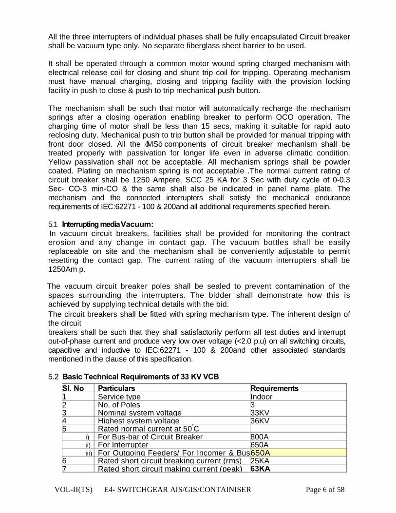
VOL-II(TS) E4- SWITCHGEAR AIS/GIS/CONTAINISER Page 6 of 58
All the three interrupters of individual phases shall be fully encapsulated Circuit breaker shall be vacuum type only. No separate fiberglass sheet barrier to be used.
It shall be operated through a common motor wound spring charged mechanism with electrical release coil for closing and shunt trip coil for tripping. Operating mechanism must have manual charging, closing and tripping facility with the provision locking facility in push to close & push to trip mechanical push button.
The mechanism shall be such that motor will automatically recharge the mechanism springs after a closing operation enabling breaker to perform OCO operation. The charging time of motor shall be less than 15 secs, making it suitable for rapid auto reclosing duty. Mechanical push to trip button shall be provided for manual tripping with front door closed. All the ‘MS’ components of circuit breaker mechanism shall be treated properly with passivation for longer life even in adverse climatic condition. Yellow passivation shall not be acceptable. All mechanism springs shall be powder coated. Plating on mechanism spring is not acceptable .The normal current rating of circuit breaker shall be 1250 Ampere, SCC 25 KA for 3 Sec with duty cycle of 0-0.3 Sec- CO-3 min-CO & the same shall also be indicated in panel name plate. The mechanism and the connected interrupters shall satisfy the mechanical endurance requirements of IEC:62271 - 100 & 200and all additional requirements specified herein. 5.1 Interrupting media Vacuum:
In vacuum circuit breakers, facilities shall be provided for monitoring the contract erosion and any change in contact gap. The vacuum bottles shall be easily replaceable on site and the mechanism shall be conveniently adjustable to permit resetting the contact gap. The current rating of the vacuum interrupters shall be 1250Am p.
The vacuum circuit breaker poles shall be sealed to prevent contamination of the spaces surrounding the interrupters. The bidder shall demonstrate how this is achieved by supplying technical details with the bid. The circuit breakers shall be fitted with spring mechanism type. The inherent design of the circuit breakers shall be such that they shall satisfactorily perform all test duties and interrupt out-of-phase current and produce very low over voltage (<2.0 p.u) on all switching circuits, capacitive and inductive to IEC:62271 - 100 & 200and other associated standards mentioned in the clause of this specification. 5.2 Basic Technical Requirements of 33 KV VCB
SI. No Particulars Requirements 1 Service type Indoor 2 No. of Poles 3 3 Nominal system voltage 33KV 4 Highest system voltage 36KV 5 Rated normal current at 50°C
i) For Bus-bar of Circuit Breaker 800A ii) For Interrupter 650A iii) For Outgoing Feeders/ For Incomer & Bus 650A
6 Rated short circuit breaking current (rms) 25KA 7 Rated short circuit making current (peak) 63KA

VOL-II(TS) E4- SWITCHGEAR AIS/GIS/CONTAINISER Page 7 of 58
8 Rated short time current withstand capability for 3 sec.
25KA(Panel)/25KA (Interrupter) 9. Rated insulation level:
i) One minute power frequency withstand 70KV ii) Impulse withstand voltage to earth with 170KV
10 First — pole — to clear factor 1.5 11 Rated operating sequence (for auto reclosing) 0-0.3 Sec- CO-3 min-CO 12 Maximum break time 3 cycles 13 Rated out of phase breaking current 25% of the symmetrical short14 Maximum pole scatter 10 mili seconds 15 Rated Auxiliary supply for spring charge motor, 230V A.C 16 Rated supply voltage for trip/close coil 48V D.C 17 No load line/cable breaking current capacity 25A 18 No load transformer breaking current capacity 25A 19 Minimum creepage distance (mm) 900 mm 20 Minimum protected creepage distance (mm) As Per IS
6.0 OPERATING MECHANISM
General 6.1 The operating mechanism of the circuit breaker shall be motor wound spring
charged type. It shall be electrically and mechanically trip free with anti-pumping device (as per IEC:694 definition). All working parts in the mechanism shall be of corrosion resistant material. Self-lubricating, wearing resistant bearings shall be provided in the mechanism.
6.2 The mechanism shall fully close the circuit breaker and sustain it in the closed
position against the forces of the rated making current and shall fully open the circuit breaker without undue contact bounce at a speed commensurate with that shown by tests to be necessary to achieve the rated breaking capacity in accordance with IEC:56 or IS:13118. The mechanism shall be capable of being locked in either the open or closed position. The mechanism shall be capable of fully closing and opening again after the auto-reclose time interval specified as 0.3 second in this specification.
6.3 Spring mechanism (In case of Spring Charged VCB) 6.3.1 The spring operating mechanism shall be with spring charging motor,
openingand closing springs with limit switches and all accessories necessary for automatic charging. In normal operation, recharging of the operating springs shall commence immediately and automatically upon completion of the closing operation so that a complete sequence of closing and opening operation should be possible.
6.3.2 It shall be possible to hand charge the operating spring with the circuit breaker
in either the open or closed position conveniently from the ground level. Closure whilst a spring charging operation is in progress shall be prevented and release of the springs shall not be possible until they are fully charged.
6.3.3 The state of charge of the operating springs shall be indicated by a mechanical
device showing 'SPRING CHARGED' when closing spring is fully charged and
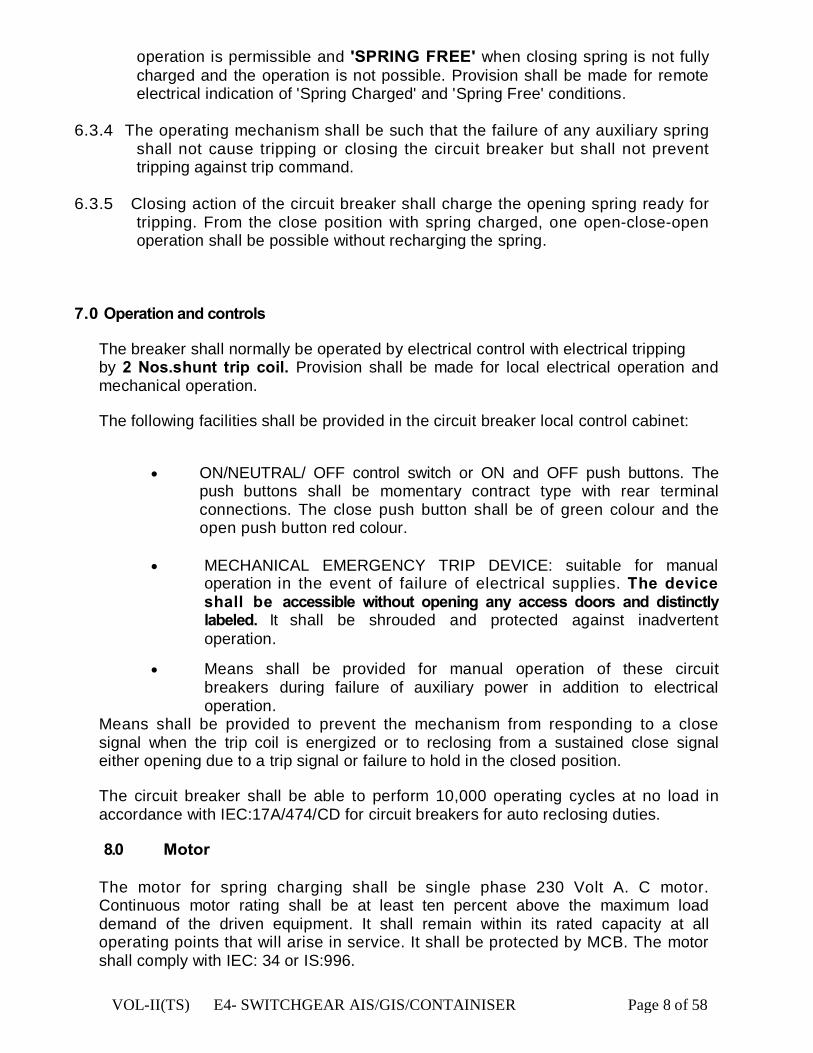
VOL-II(TS) E4- SWITCHGEAR AIS/GIS/CONTAINISER Page 8 of 58
operation is permissible and 'SPRING FREE' when closing spring is not fully charged and the operation is not possible. Provision shall be made for remote electrical indication of 'Spring Charged' and 'Spring Free' conditions.
6.3.4 The operating mechanism shall be such that the failure of any auxiliary spring
shall not cause tripping or closing the circuit breaker but shall not prevent tripping against trip command.
6.3.5 Closing action of the circuit breaker shall charge the opening spring ready for
tripping. From the close position with spring charged, one open-close-open operation shall be possible without recharging the spring.
7.0 Operation and controls
The breaker shall normally be operated by electrical control with electrical tripping by 2 Nos.shunt trip coil. Provision shall be made for local electrical operation and mechanical operation.
The following facilities shall be provided in the circuit breaker local control cabinet:
• ON/NEUTRAL/ OFF control switch or ON and OFF push buttons. The push buttons shall be momentary contract type with rear terminal connections. The close push button shall be of green colour and the open push button red colour.
• MECHANICAL EMERGENCY TRIP DEVICE: suitable for manual operation in the event of failure of electrical supplies. The device shall be accessible without opening any access doors and distinctly labeled. It shall be shrouded and protected against inadvertent operation.
• Means shall be provided for manual operation of these circuit breakers during failure of auxiliary power in addition to electrical operation.
Means shall be provided to prevent the mechanism from responding to a close signal when the trip coil is energized or to reclosing from a sustained close signal either opening due to a trip signal or failure to hold in the closed position.
The circuit breaker shall be able to perform 10,000 operating cycles at no load in accordance with IEC:17A/474/CD for circuit breakers for auto reclosing duties.
8.0 Motor
The motor for spring charging shall be single phase 230 Volt A. C motor. Continuous motor rating shall be at least ten percent above the maximum load demand of the driven equipment. It shall remain within its rated capacity at all operating points that will arise in service. It shall be protected by MCB. The motor shall comply with IEC: 34 or IS:996.

VOL-II(TS) E4- SWITCHGEAR AIS/GIS/CONTAINISER Page 9 of 58
9.0 THERMAL RATING OF SWITCHGEAR
All current carrying parts including breaker Relay shall be governed by IEC 62271-1. All isolating contacts shall be silver plated.
10.0 AUXILIARY POWER SUPPLY:
The operating mechanism shall be suitable to operate with the following auxiliary Power supplies.
a) 230V,50Hz Single phase A.C- For spring charging motor b)DC supply 48 Volts- For close and open coils.
The DC supply shall be from Battery Bank.
The mechanism shall be designed to operate satisfactorily despite fluctuations of Auxiliary power supplies as under:
AC supply: Voltage From 115% to 85% of normal voltage Frequency: ±3% of normal frequency DC supply: Voltage From 120% to 70% of normal voltage
11.0 INTERLOCKS Circuit breaker can be inserted only in open position. Likewise circuit breaker in closed position cannot be withdrawn. Attempt to draw out closed breaker shall not trip the breaker.
The circuit breaker shall operate only in one of the three defined positions i.e. service, test and isolated. The breaker shall not close in any of the intermediate positions.
The circuit breaker cannot be inserted into service position till auxiliary contacts are made. Similarly interlock shall prevent auxiliary contacts from being disconnected, if circuit breaker is in service position.
12.0 SAFETY SHUTTERS
Safety shutters shall be metallic and shall be provided to cover up the fixed High voltage contacts on bus bar and cable sides when the truck is moved to Test / isolated position. The shutters shall move automatically, through a Linkage with the movement of the truck and shall be of gravity fall type only. It shall be possible to padlock shutters individually. 13.0 FIXED ISOLATING CONTACTS
Switch gear cubicle shall have seal off bushing arrangement between the circuit

VOL-II(TS) E4- SWITCHGEAR AIS/GIS/CONTAINISER Page 10 of
breaker compartment and bus bar / C.T. cum cable compartment, i.e. the fixed isolating contacts shall be embedded in epoxy cast bushing so the these act as seal off bushing to prevent transfer of arc from one compartment to the other in the event of internal arc within the cubicle & must be tested for internal arc 25 kA for 1 sec in all three HV compartments as per new IEC 62271-200.
14.0 AUXILIARY SWITCH AND AUXILIARY PLUG &SOCKET
There shall be minimum 6NO and 6NC contacts in breaker auxiliary switch (10 amps DC rating) shall be provided in each circuit breaker.
. 15.0 ELECTRICAL & MECHANICAL POSITION INDICATION.
In addition to mechanical position indication in breaker for test and service position, electrical indication shall also be provided through limit switch. There shall be minimum 2NO +2 NC contacts available in each position for electrical indication and for any other interlocking purpose.
16.0 CURRENT TRANSFORMER
Current transformers, three per circuit breaker, shall be of indoor, single phase, resin cast and shall comply with IEC:185 and IS:2705, suitable for operation in hot and humid atmospheric conditions described in service condition. They shall be mounted inside the panel.
16.1 Core
16.1.1 High grad non- ageing cold rolled grain oriented (CRGO M4 or better grade) silicon steel of low hysteresis loss and permeability shall be used for the core so as to ensure specified accuracy at both normal and over currents. The flux density shall be limited to ensure that there is no saturation during normal service.
16.1.2 The instrument security factor of the core shall be low enough so as not to cause damage to the instruments in the event of maximum short circuit current.
16 . 2 Windings
16.2.1 The secondary windings shall be made of electrolytic copper with suitable insulation. The conductor shall be of adequate cross- section so as to limit the temperature rise even during short circuit conditions. The insulation of windings and connections shall be free from composition liable to soften, coze, shrink or collapse during service.
16.2.2 Polarity shall be indelibly marked on each current transformer and at the lead and termination at associated terminal blocks. CTs with multi ratio winding shall be clearly tabulated to show the connections required for different

VOL-II(TS) E4- SWITCHGEAR AIS/GIS/CONTAINISER Page 11 of
ratios. Similar numbers shall be marked on terminal block arrangement and wiring diagram. Apart from the above marking and those to be provided as per IEC 185 or IS 2705, other markings shall be provided in consultation with owner.
16.2.3 The continuous current rating of the primary winding shall be one hundred and twenty percent of the normal rated current.
16.2.4 Secondary windings of current transformers shall be used for metering,instrumentation and protection and shall be rated for continuous current of one hundred and twenty percent of normal rated current of primary winding. Current transformers shall be three core window/bar primary for higher rating or wound primary for lower rating. Maximum VA burden shall be of 15 VA and shall be rated for full short circuit current 25 KA for 1 second. Out of three cores one Core having 0.2 class (Metering) & other two cores having 5P20 (Protection) class accuracy. Current Ratio: 400-200/1-1-1 Amp No. of Cores: 03 Burden: 15 VA for each core
Technical Requirements SI. No
Particulars Requirements
1 Function To control 33 KV Feeder & HV side of 33/11KV power transformers of ratings between 3.15MVA to 12.5MVA
2 Requirement The CTs in the 33 KV Indoor VCB switchgear panel should have three cores as follows.
3 Transformation Ratio Category- A (For TFR) 400-200/1-1-1-A
Category- B (For Feeder)
4 Rated Burden (VA) Core:1: 15 VA , Core:2: 15 VA, Core:3:15 VA
Core:1: 15 VA , Core:2: 15 VA, Core:3:15 VA
5 Class of Accuracy Core:1: 0.2 , Core:2: 5P20, Core:3: 5P20
Core:1: 0.2 , Core:2: 5P20,
Core:3: 5P20
6 Instrument Security Factor
Core- 1:- <5
Core- 1:- <5
7 Purpose Core:1: Metering , Core:2: Differential, Core:3:O/C& E/F & REF
Core:1: Metering , Core:2: Spare Core:3:O/C& E/F & REF
8 Rated/Highest syatem 33/36 KV 9 Short Time Rating 25KA rms for 3 seconds 10 Power frequency 1 min
voltage withstand level/Insulation Level: -Impulse Voltage1.2/50ps wave
70 KV/170KV
VOL-II(TS) E4- SWITCHGEAR AIS/GIS/CONTAINISER Page 12 of
17.0 Tests
The CTs shall be tested in accordance with the requirements of the type tests and routine tests as per the latest issues IEC:185 or IS:2705.The tests to be conducted shall include:
17.1 Type Tests:
• L ightning impulse vol tage:
• Power frequency wet withstand voltage;
• Temperature rise;
• Short time current;
• Composite error;
• Accuracy test (for measuring core);
• Instrument security current (for measuring core);
17.2 Routine tests
• Verification of terminal marking and polarity;
• Power frequency dry withstand test on primary windings;
• Power frequency dry withstand test on secondary windings;
• Power frequency dry withstand test between sections;
• Over voltage inter-turn test;
• Composite error;
• Tu rn ra t i o ;
• Accuracy test (for measuring core);
• Current error and phase displacement (for protection core);
• Knee point voltage and magnetizing current test (for PS class);Secondary winding resistance (for PS class).
18.0 IVT:
The 33 KV Indoor voltage transformers are required to meet the following basic technical requirements (Reference standards: IEC:186, IS:3156 and associated standards listed in the specification):
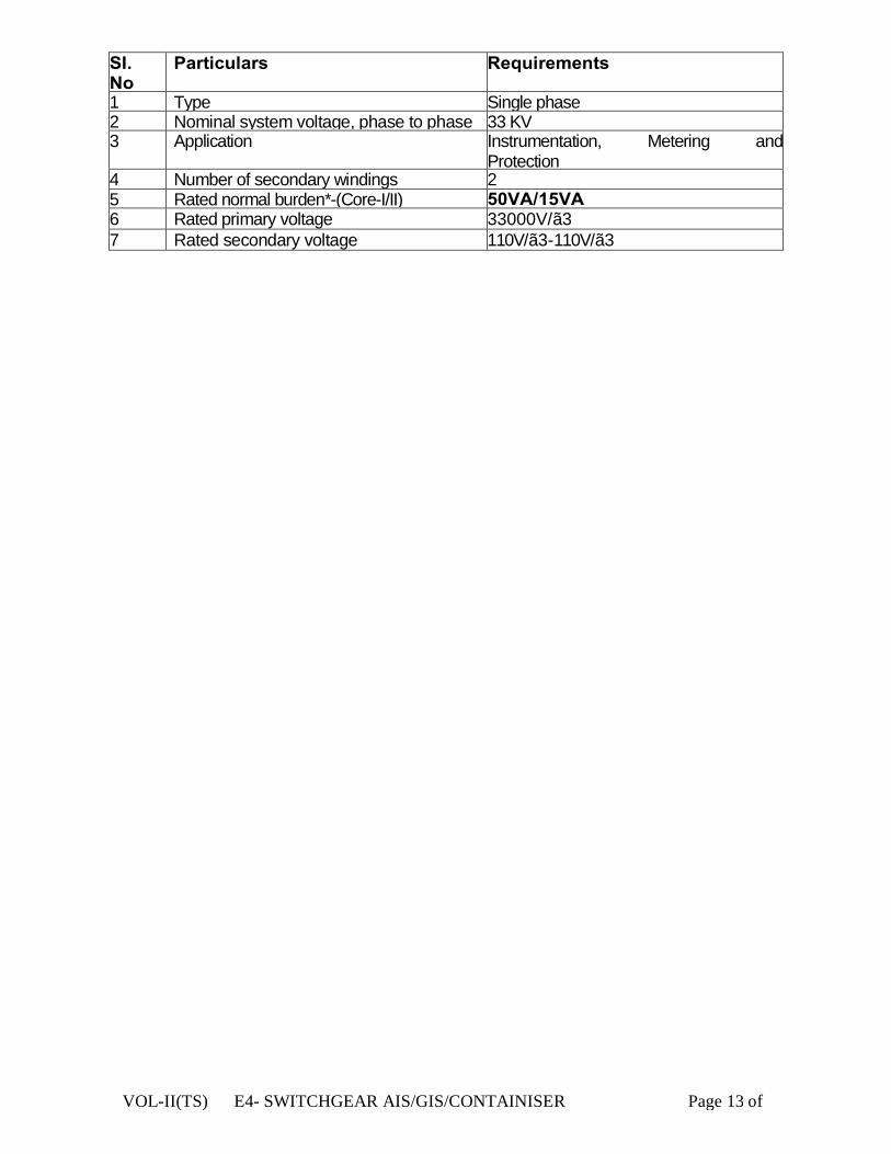
VOL-II(TS) E4- SWITCHGEAR AIS/GIS/CONTAINISER Page 13 of
SI. No
Particulars Requirements
1 Type Single phase 2 Nominal system voltage, phase to phase 33 KV 3 Application Instrumentation, Metering and
Protection 4 Number of secondary windings 2 5 Rated normal burden*-(Core-I/II) 50VA/15VA 6 Rated primary voltage 33000V/√3 7 Rated secondary voltage 110V/√3-110V/√3

VOL-II(TS) E4- SWITCHGEAR AIS & GIS Page 14 of 58
8 Class of accuracy-(Core-I/II) 0.2/3P 9 Rated insulation level: (Primary
winding) (Phase to earth)
i) One minute power frequency withstand voltage to earth (wet and
70KV
ii) Impulse withstand voltage to earth with 1.2/50 ilsec wave of +ve and —ve polarity (peak)
170KV
10 One minute power frequency withstand voltage of secondary
Between phase to earth 3KV Between sections 3KV
11 Rated voltage factor Continuous 1.2 For 30 seconds 1.5
* The burden indicated is the minimum acceptable to the Employer. The Contractor shall ensure that the rated outputs of the voltage transformers are adequate to meet at least 120 percent of the connected load (burden).
18.1 GENERAL
The voltage transformers to be supplied under this specification shall be of Indoor, single phase Polycrate complying with IEC:185 and IS:3156 suitable for operation in hot and humid atmospheric conditions described in this document.
18.2 Duty requirement
33 KV Voltage transformer for all the indicating instruments and measuring meters in the primary substation on 33 KV side. It shall be of indoor, 1-Phase or 3- phase Poly- crate type.
18.3 Core
High grade non-ageing cold rolled grain oriented (CRGO-M4 or better) silicone steel of low hysteresis loss and permeability shall be used for core so as to ensure accuracy at both normal and or over Voltages. The flux density shall be limited to 1.6 Tesla at normal voltage and frequency. There shall be no saturation at any stage during operation.

VOL-II(TS) E4- SWITCHGEAR AIS & GIS Page 15 of 58
The instrument security factor of the core shall be low enough so as not to cause damage to the instruments in the event of maximum short circuit current or over voltages.
18.4 Windings
The primary and secondary windings shall be electrolytic copper of high purity and conductivity and covered with double paper insulation. The conductor shall be of adequate cross-section so as to limit the temperature rise even during maximum over voltages.
The insulation of windings and connections shall be free from composition liable to soften, ooze, shrink or collapse during service.
18.5 The secondary windings of the voltage transformers shall also be suitable for continuous over voltage corresponding to the maximum system voltage at the primary winding. The winding supports shall be suitably reinforced to withstand normal handling and the thermal and dynamic stresses during operation without damage.
18.6 The voltage transformer secondary circuits will be taken out to form the star point and earthed at one point outside the voltage transformers.
18.7 Both primary and secondary winding terminals shall be clearly and indelibly marked to show polarity in accordance with IEC:186. The connections required for different secondary windings in case of multi-winding voltage transformers shall be clearly indicated in terminal blocks and the wiring diagrams.
18.8 Fuse protection The Primary winding shall be protected by HRC Fuses in suitable holder designed by the manufacturers. The secondary windings shall be protected by HRC cartridge fuses in fuse holder consisting of carriers and bases. The carriers and bases shall be of high grade flame retarding and non-hygroscopic moulded insulating materials with hard glass surface. Each fuse shall be identified with engraved plastic label. Potential transformer shall be 3nos single phase & there shall be two cores. One core having 0.2 Class (Metering) & other having 3P Class (Protection). Bus P.T. shall be mounted in a separate draw out carriage.
VOL-II(TS) E4- SWITCHGEAR AIS & GIS Page 16 of 58
19.0 TEST AND INSPECTIONS
19.1 The voltage transformers shall be tested in accordance with the requirements of the type tests and routine tests as provided in the latest issues of IEC:186 or IS:3516.
The tests to be conducted shall include; 19.2 Type tests:
• Lightning impulse vol tage test ; • High voltage power frequency wet withstand voltage; • Tempera tu re r i se tes t ; • Short circuit withstand capability test; • Determination of limits of voltage error and
phase displacement 19.3 Routine tests:
• Verification of terminal marking and polarity; • Power frequency withstand tests on primary
winding; • Power frequency dry withstand tests on secondary
winding; • Power frequency withstand tests between sections; • Determination of limits of voltage errors and phase
displacement; • Insulating Resistance measurement. • Partial discharge measurement.
Voltage Ratio: 33000/√3 / 110/√3-110/√3. No. of Cores: 02 Burden: 50 VA for Metering & 15 VA for protection
20.0 PRESSURE DISCHARGE FLAPS
Pressure discharge flaps shall be provided at the top in all high voltage compartments for the exit of hot gases in the event of internal arc in any of the compartments.
21.0 BUSBARS
Bus bar material shall be of high conductivity electrolytic copper only and accessibility of the same shall be from top only. All bus bars shall be tubular /rectangular design insulated with heat shrinkable BPTM compound sleeves and joints shall have sufficient clearances in order to meet the BIL (70kV RMS and 170 kVp) withstand. Phase identification shall be made at the end by coloured tape.

VOL-II(TS) E4- SWITCHGEAR AIS & GIS Page 17 of 58
22.0 EARTH BUS
There shall be a continuous copper bus at the bottom of the panel. Earth bus shall be robust and shall be capable of carrying full short circuit current 25 KA for 1 second. Doors, covers and all non-current carrying metallic parts shall be earthed through flexible copper breading of adequate size. This also includes instrument casing and cable armour which are also connected to the earth bus. Earth bus must be tested for 25 KA for 1 sec.
23.0 BUS & CABLE EARTHING
Each feeder shall be provided with fault make type Earth switch duly interlocked with circuit breaker. Unless the breaker is tripped & brought to test position, the earthing switch cannot be operated. Earth Switch should be fully type tested for STC withstand of 25kA for 1 seconds.
24.0 CABLE COMPARTMENT
It shall be at the rear side with rear bolted box type back covers. There shall be an inspection window at the rear back cover enabling operator to have visual inspection without opening back cover in live condition .Viewing window at the rear side shall be of poly carbonate only and shall be tested for internal arc. The gland plate of cable chamber shall be of minimum 3mm thickness MS sheet in two halves section. Sufficient headroom of 750 mm shall be provided for cable termination.
25.0 LOW VOLTAGE COMPARTMENT
Low voltage compartment shall be mounted at the front on the top of breaker compartment and shall also have hinged type of door. All wiring shall be routed through PVC ducts and shall be terminated on to stud type terminal with plastic cover. For current transformer terminal shall be disconnecting link type only. The wire shall be of 1.1KV grade and suitable for 2KVrms for 1 minute power frequency high voltage.
26.0 CONTROL AND POWER CABLE ENTRY Control cable entry shall be from front and there should be a possibility of terminating to LV chamber from both right hand and left hand side. Power cable entry shall be from rear bottom. Provision shall be available for entry of power cable from rear bottom.
The CR Panel (Instrument Chamber) should be mounted on top of the VCBPanel.
VOL-II(TS) E4- SWITCHGEAR AIS & GIS Page 18 of 58
Control panel (inbuilt) with protective relay and meter shall be provided by the supplier suitable for above breakers. The equipment shall have protection scheme with the following relays:
27.0 PROTECTION RELAYS FOR FEEDER:
The offered relays shall be multifunction numerical type only. The aux relays for lockout, transfer fault indication etc can be electro-mechanical type. All Numerical relays shall have minimum following features
§ Relay shall be IEC 61850 compliant Numerical & suitable for 1A
secondary CT current & 110 V IVT secondary supply.
27.1 Over current & Earth fault relay: § Relay shall have 3 phase directional and non-direction (site
selectable feature) over current and earth fault protection. It shall have three stages with first stage programmable as IDMT or DT. The second and third stages shall be programmable as DT or instantaneous.
§ Relay shall have thermal overload protection. § Relay shall have negative sequence over current protection. § Relay shall have adoptive & creative logics for meeting the
requirement § Relay shall have 4 shots auto reclose function built-in § Relay shall be with under and over voltage protection elements
provided § Relay shall have under frequency protection facility at least two
stages.
Details are given below separately:
28.0 PROTECTION RELAYS FOR TRANSFORMER:
The offered relays shall be multifunction numerical type only. The aux relays for lockout, transfer fault indication etc can be electro-mechanical type. All Numerical relays shall have minimum following features
§ Relay shall be IEC 61850 compliant Numerical & suitable for 1A
secondary CT current & 110 V IVT secondary supply.
28.1 Over current & Earth fault relay: § Relay shall have 3 phase directional and non-direction (site
selectable feature) over current and earth fault protection. It shall

VOL-II(TS) E4- SWITCHGEAR AIS & GIS Page 19 of 58
have three stages with first stage programmable as IDMT or DT. The second and third stages shall be programmable as DT or instantaneous.
§ Relay shall have thermal overload protection. § Relay shall have negative sequence over current protection. § Relay shall have adoptive & creative logics for meeting the
requirement § Relay shall have 4 shots auto reclose function built-in § Relay shall be with under and over voltage protection elements
provided § Relay shall have under frequency protection facility atleast two
stages.
Details are given below separately:
28.2 Transformer Differential Relay: The Transformer Differential protection relay shall consist of two
winding protection, two REF protections, V/f protection etc. Details are given below separately:
28.3 Specification for Numerical Directional & Non-Directional Over Current and Earth Fault Protection. 28.3.1. General A comprehensive communicable numerical protection should be offered by the relay. High level of security should be built-in the relay to avoid any mal operation causing over protection of the system or any non-operation of the relay causing under protection. Should have flexibility to customize the relay for intended applications as may be desired at site, in other words the relay should not have very limited features rendering it equipment specific. The relay should have high immunity to electrical and electromagnetic interference and also continuous supervision of hardware and software should be done to ensure enhanced system reliability and availability, the relay should have auto diagnostic fault indication to facilitate fault location and repair after detection of internal relay fault. The compulsory features required by the relay to be fulfilled are listed as below 28.3.2. Application The relay will be required for applications where time graded Directional & Non-Directional (site selectable feature) o/c and e/f protection is required. The Directional & Non-Directional (site selectable feature) earth fault protection should provide suitable sensitivity for most systems where the earth fault current is limited. Typically the relay should be
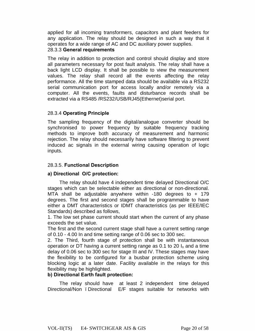
VOL-II(TS) E4- SWITCHGEAR AIS & GIS Page 20 of 58
applied for all incoming transformers, capacitors and plant feeders for any application. The relay should be designed in such a way that it operates for a wide range of AC and DC auxiliary power supplies. 28.3.3 General requirements The relay in addition to protection and control should display and store all parameters necessary for post fault analysis. The relay shall have a back light LCD display. It shall be possible to view the measurement values. The relay shall record all the events affecting the relay performance. All the time stamped data should be available via a RS232 serial communication port for access locally and/or remotely via a computer. All the events, faults and disturbance records shall be extracted via a RS485 /RS232/USB/RJ45(Ethernet)serial port.
28.3.4 Operating Principle
The sampling frequency of the digital/analogue converter should be synchronised to power frequency by suitable frequency tracking methods to improve both accuracy of measurement and harmonic rejection. The relay should necessarily have software filtering to prevent induced ac signals in the external wiring causing operation of logic inputs. 28.3.5. Functional Description a) Directional O/C protection: The relay should have 4 independent time delayed Directional O/C stages which can be selectable either as directional or non-directional. MTA shall be adjustable anywhere within -180 degrees to + 179 degrees. The first and second stages shall be programmable to have either a DMT characteristics or IDMT characteristics (as per IEEE/IEC Standards) described as follows, 1. The low set phase current should start when the current of any phase exceeds the set value. The first and the second current stage shall have a current setting range of 0.10 - 4.00 In and time setting range of 0.06 sec to 300 sec. 2. The Third, fourth stage of protection shall be with instantaneous operation or DT having a current setting range as 0.1 to 20 In and a time delay of 0.06 sec to 300 sec for stage III and IV. These stages may have the flexibility to be configured for a busbar protection scheme using blocking logic at a later date. Facility available in the relays for this flexibility may be highlighted. b) Directional Earth fault protection: The relay should have at least 2 independent time delayed Directional/Non –Directional E/F stages suitable for networks with
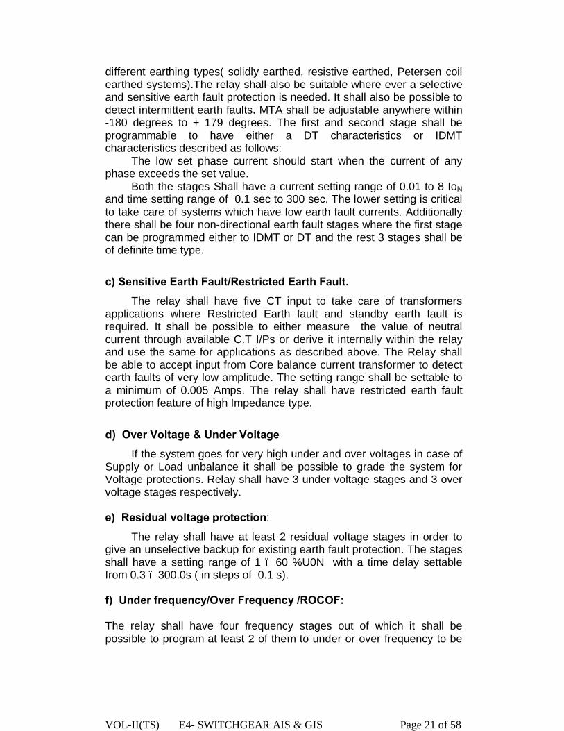
VOL-II(TS) E4- SWITCHGEAR AIS & GIS Page 21 of 58
different earthing types( solidly earthed, resistive earthed, Petersen coil earthed systems).The relay shall also be suitable where ever a selective and sensitive earth fault protection is needed. It shall also be possible to detect intermittent earth faults. MTA shall be adjustable anywhere within -180 degrees to + 179 degrees. The first and second stage shall be programmable to have either a DT characteristics or IDMT characteristics described as follows: The low set phase current should start when the current of any phase exceeds the set value. Both the stages Shall have a current setting range of 0.01 to 8 IoN and time setting range of 0.1 sec to 300 sec. The lower setting is critical to take care of systems which have low earth fault currents. Additionally there shall be four non-directional earth fault stages where the first stage can be programmed either to IDMT or DT and the rest 3 stages shall be of definite time type.
c) Sensitive Earth Fault/Restricted Earth Fault. The relay shall have five CT input to take care of transformers applications where Restricted Earth fault and standby earth fault is required. It shall be possible to either measure the value of neutral current through available C.T I/Ps or derive it internally within the relay and use the same for applications as described above. The Relay shall be able to accept input from Core balance current transformer to detect earth faults of very low amplitude. The setting range shall be settable to a minimum of 0.005 Amps. The relay shall have restricted earth fault protection feature of high Impedance type.
d) Over Voltage & Under Voltage If the system goes for very high under and over voltages in case of Supply or Load unbalance it shall be possible to grade the system for Voltage protections. Relay shall have 3 under voltage stages and 3 over voltage stages respectively. e) Residual voltage protection:
The relay shall have at least 2 residual voltage stages in order to give an unselective backup for existing earth fault protection. The stages shall have a setting range of 1 – 60 %U0N with a time delay settable from 0.3 – 300.0s ( in steps of 0.1 s). f) Under frequency/Over Frequency /ROCOF: The relay shall have four frequency stages out of which it shall be possible to program at least 2 of them to under or over frequency to be

VOL-II(TS) E4- SWITCHGEAR AIS & GIS Page 22 of 58
suitable for various load sharing applications. The under frequency stages shall be settable any where within a frequency range of 40.0 - 60.0 Hz. With the flexibility to block any mal operation on event on under voltage. All stages shall be of definite time type with a setting range of 0.10) – 300.0 s ( in steps of 0.02 s). The relay shall also have the facility to detect a rate of change of frequency for load shedding applications , to speed up operation time in over- and under-frequency situations and to detect loss of grid. Pick up setting shall be settable from 0.2 – 10.0 Hz/s (step 0.1 Hz/s). g) The relay in addition to the above basic function should also provide the following functions,
1. The relay should have the protection feature which allows the relay to trip the upstream circuit breaker when a local breaker failure condition is detected and should be energised both from operation of the relay or by an external trip. 2. The relay shall also have the feature of auto reclosure with independently programmable dead time and reclaim time for each shot. The function shall be programmable for at least 4 shots of auto reclosure. 3. The relay should measure the following standard quantities,
i.) It shall be possible to view the current voltage phasors as well in the graphical mimic display.
ii.) Phase current(Positive, negative and zero sequence currents) iii.) Phase Voltage(Positive, negative and zero sequence
voltages) iv.) Neutral current v.) Frequency vi.) Active and Reactive Power vii.) Power factor viii.) Harmonics of current and voltages which shall be possible to
view as a diagram on the display. ix.) Relay should be able to measure the true RMS value up to
15th harmonics 4. The relay shall have atleast two independent setting groups. The relay shall automatically switch from one setting group to another depending on system conditions (such as failure of incomer supply, which causes fault level to decrease etc.) 5. The relay shall have a facility to have communication on IEC61850 protocol through redundant rear port for SAS connectivity without use of any external converter. Further, the test levels of EMI as indicated in IEC 61850 shall be applicable to these. The relay shall support peer to peer communication.

VOL-II(TS) E4- SWITCHGEAR AIS & GIS Page 23 of 58
The relays shall generate GOOSE messages as per IEC 61850 standards for interlocking/tripping and also to ensure interoperability with third party relays.
a) Necessary user friendly configuration tool shall be provided to configure the relays. It should be compatible with SCL/SCD files generated by a third party system.
b) Goose signals shall be freely configurable for any kind of signals using graphic tool/user friendly software.
Bidder shall also ensure adequate hardware.
7. The Relay shall have facility for Time synchronization on IRIG B port.
h. Relay hardware: The relay should be modular type. It will be installed on the top of the switchgear panel. Standard terminal blocks should be located at the rear of the relay providing connections for all input and output circuits. i. Output relays: The relay should have up to 2-CT inputs. They should provide atleast 6 optically isolated inputs and atleast 7 programmable outputs. They should be arranged in response to any or all of the available functions by suitably setting the output relays. The protection and control function to which these relays respond should be selectable via the menu system of the relay. One output relay shall be permanently assigned for self-supervision. H. The Relay shall also have the following functionality/Features..
* Thermal overload protection.
Negative sequence over current.
Permanent Self-Test.
x.) Circuit breaker maintenance information.
xi.) Broken conductor detection by measuring I2/I1 .
xii.) Cold load pickup function to change the settings when the
protected object is connected to a network i.e., at starting allowing the
set value being lower than the connected inrush current.
xiii.) The relay shall also have the feature of Inrush blocking through 2nd
harmonic detection.
xiv.) Disturbance recorder & Event recorder facilities.8 fault records
shall be possible in each protection stage.
xv.) Front RS232/USB port for communication to LAPTOP .

VOL-II(TS) E4- SWITCHGEAR AIS & GIS Page 24 of 58
xvi.) The relay shall have a facility for C.T. Supervision, P.T. Supervision
and Trip Circuit Supervision.
Relay shall support customer-defined programmable logic for Boolean signals. It shall be possible to form equations using AND, OR, NOT gates.
29.0 Detail on Differential Protection: a) Transformer differential protection scheme shall be of numerical relay (low impedance type) suitable for two winding Transformer. b) Shall be triple pole type with faulty phase identification/indication. c) Shall have an operating time not greater than 30ms at 5 times the rated current. d) Shall have three instantaneous high set over current units. e) Shall have an adjustable bias setting range of 10 – 50%. f) Suitable for rated 1 amp current. g) Shall have 2nd harmonics or other inrush restraint features and also should be stable under normal over fluxing conditions. Magnetizing inrush inrush features shall not be achieved any intentional time delay. h) Shall have an operating current setting of 15% or less. I) Shall have an internal feature of the relays to take care of the angle and ratio correction. j) Shall have provision of self monitoring and diagnostic feature. k) Shall have provision of recording features to record graphic from of instantaneous values during faults and disturbances for the pre and post fault period and during running conditions. l) Current in all the windings in separate analog channels and voltage in one channel. The disturbance recorder shall have the facility to record the following external digital channel signals apart from the digital signals pertaining to differential relay. * REF protection operated. * HV breaker status *LV breaker status. * Buchholz /OLTC Buchholz /PRV alarm/trip. * WTI/OTI alarm/trip * MOG alarm Necessary hardware and software for automatic up-loading the data captured by disturbance recorder to the personal computer. The relay shall have three stages of definite time overcurrent protection as backup operating with separate measuring systems for the evaluation of the three phase currents, the negative sequence current and the residual current.
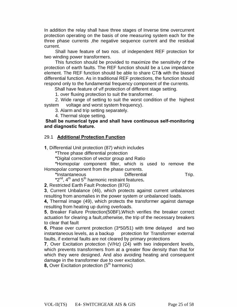
VOL-II(TS) E4- SWITCHGEAR AIS & GIS Page 25 of 58
In addition the relay shall have three stages of Inverse time overcurrent protection operating on the basis of one measuring system each for the three phase currents ,the negative sequence current and the residual current. Shall have feature of two nos. of independent REF protection for two winding power transformers. This function should be provided to maximize the sensitivity of the protection of earth faults. The REF function should be a Low impedance element. The REF function should be able to share CT’s with the biased differential function. As in traditional REF protections, the function should respond only to the fundamental frequency component of the currents. Shall have feature of v/f protection of different stage setting. 1. over fluxing protection to suit the transformer. 2. Wide range of setting to suit the worst condition of the highest system voltage and worst system frequency). 3. Alarm and trip setting separately. 4. Thermal slope setting. Shall be numerical type and shall have continuous self-monitoring and diagnostic feature. 29.1 Additional Protection Function 1, Differential Unit protection (87) which includes *Three phase differential protection *Digital correction of vector group and Ratio *Homopolar component filter, which is used to remove the Homopolar component from the phase currents. *Instantaneous Differential Trip. *2nd, 4th and 5th harmonic restraint features. 2, Restricted Earth Fault Protection (87G) 3, Current Unbalance (46), which protects against current unbalances resulting from anomalies in the power system or unbalanced loads. 4, Thermal image (49), which protects the transformer against damage resulting from heating up during overloads. 5, Breaker Failure Protection(50BF),Which verifies the breaker correct actuation for clearing a fault,otherwise, the trip of the necessary breakers to clear that fault 6, Phase over current protection (3*50/51) with time delayed and two instantaneous levels, as a backup protection for Transformer external faults, if external faults are not cleared by primary protections 7, Over Excitation protection (V/Hz) (24) with two independent levels, which prevents transformers from at a greater flow density than that for which they were designed. And also avoiding heating and consequent damage in the transformer due to over excitation. 8, Over Excitation protection (5th harmonic)
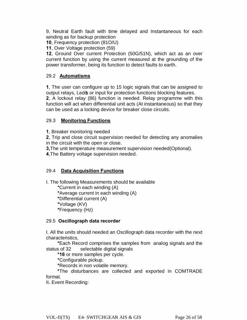
VOL-II(TS) E4- SWITCHGEAR AIS & GIS Page 26 of 58
9, Neutral Earth fault with time delayed and Instantaneous for each winding as for backup protection 10, Frequency protection (81O/U) 11, Over Voltage protection (59) 12, Ground Over current Protection (50G/51N), which act as an over current function by using the current measured at the grounding of the power transformer, being its function to detect faults to earth. 29.2 Automatisms 1, The user can configure up to 15 logic signals that can be assigned to output relays, Led’s or input for protection functions blocking features. 2, A lockout relay (86) function is needed. Relay programme with this function will act when differential unit acts (At instantaneous) so that they can be used as a locking device for breaker close circuits. 29.3 Monitoring Functions 1, Breaker monitoring needed 2, Trip and close circuit supervision needed for detecting any anomalies in the circuit with the open or close. 3,The unit temperature measurement supervision needed(Optional). 4,The Battery voltage supervision needed. 29.4 Data Acquisition Functions I. The following Measurements should be available *Current in each winding (A) *Average current in each winding (A) *Differential current (A) *Voltage (KV) *Frequency (Hz) 29.5 Oscillograph data recorder I. All the units should needed an Oscillograph data recorder with the next characteristics, *Each Record comprises the samples from analog signals and the status of 32 selectable digital signals *16 or more samples per cycle. *Configurable pickup. *Records in non volatile memory. *The disturbances are collected and exported in COMTRADE format. II. Event Recording:
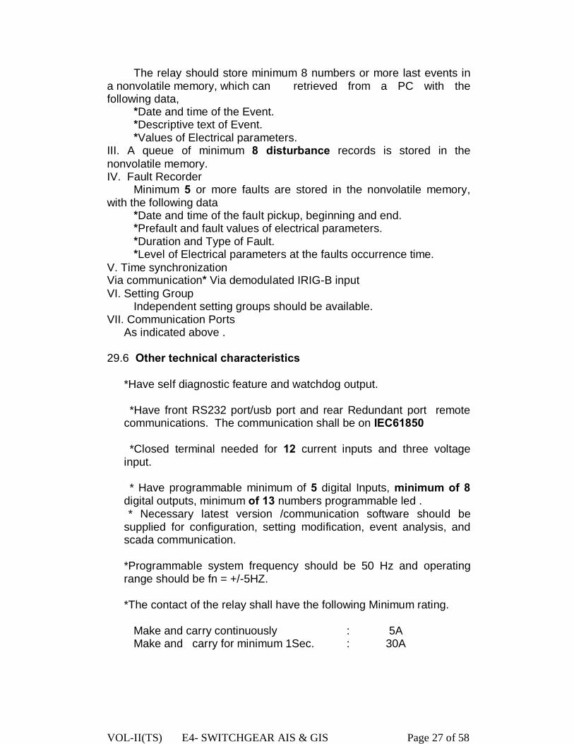
VOL-II(TS) E4- SWITCHGEAR AIS & GIS Page 27 of 58
The relay should store minimum 8 numbers or more last events in a nonvolatile memory, which can retrieved from a PC with the following data, *Date and time of the Event. *Descriptive text of Event. *Values of Electrical parameters. III. A queue of minimum 8 disturbance records is stored in the nonvolatile memory. IV. Fault Recorder Minimum 5 or more faults are stored in the nonvolatile memory, with the following data *Date and time of the fault pickup, beginning and end. *Prefault and fault values of electrical parameters. *Duration and Type of Fault. *Level of Electrical parameters at the faults occurrence time. V. Time synchronization Via communication* Via demodulated IRIG-B input VI. Setting Group Independent setting groups should be available. VII. Communication Ports
As indicated above .
29.6 Other technical characteristics
*Have self diagnostic feature and watchdog output.
*Have front RS232 port/usb port and rear Redundant port remote communications. The communication shall be on IEC61850 *Closed terminal needed for 12 current inputs and three voltage
input. * Have programmable minimum of 5 digital Inputs, minimum of 8
digital outputs, minimum of 13 numbers programmable led . * Necessary latest version /communication software should be
supplied for configuration, setting modification, event analysis, and scada communication.
*Programmable system frequency should be 50 Hz and operating range should be fn = +/-5HZ.
*The contact of the relay shall have the following Minimum rating.
Make and carry continuously : 5A Make and carry for minimum 1Sec. : 30A

VOL-II(TS) E4- SWITCHGEAR AIS & GIS Page 28 of 58
* Current balancing transformers, shall form a part of the relay. The successful Bidder shall furnish sufficient data to prove stability of the equipment up to 10 times full load through fault current. Interposing C.Ts if necessary for current balancing shall be within the scope of supply. I.C.Ts shall be of universal type of setting different ratios. 30.0 OVER FLUXING RELAY:(V/f) (a)Suitable relay with v/f characteristics shall be provided to defeat the over fluxing condition of the transformer. (b)The relay shall be a separate electromechanical relay to be connected in parallel to the over fluxing relay, if, available in any of the numerical relay i.e. if the same software is available in the numerical differential protection relay. (c) Shall have inverse time characteristics, matching with transformer over fluxing withstand capability curve. (d)shall provide an independent ‘alarm’ with the time delay continuously adjustable between 0.1 to 6.0 seconds at values of v/f between 100% to 130 % of rated values. (e)Tripping time shall be governed by v/f Vs time characteristic of the relay. (f) have a set of characteristics for various time multiplier settings. The maximum operating time of the relay shall not exceed 3 seconds and 1.5 seconds at v/f values of 1.4 and 4.5 times, the rated values, respectively. (g)Have an accuracy of operating time , better than +/-10 %.
31.0 TESTS Following tests as indicated should have been conducted for the above relays: 31.1 Soak test: All solid state equipment/system shall be subject to the Hot Soak
Test as a routine test in accordance with the procedure detailed in the following paragraph.
All solid state equipment shall be burn-in tested for minimum of 120
hours continuously under operational conditions. During the last 48 hours of testing, the ambient temperature of the test chamber shall be 50C. The temperature of the interior shall not exceed 65C.

VOL-II(TS) E4- SWITCHGEAR AIS & GIS Page 29 of 58
31.2 Type tests: 1. Impulse voltage withstand test as per Clause 6.1 of IS 8686 (for a test voltage appropriate to Class III as per Clause 3.2 of IS-8686) 2. High Frequency Disturbance test as per Clause 5.2 of IS 8686 (for a test voltage appropriate to Class III as per Clause 3.2 of IS 8686).Type tests listed under IEC-Technical Committees recommendation `TEC-57' and functional type tests listed under CIGRE Study Committee 34 (Protection) Report on simulator, Network analyser or PTL as applicable. 31.3 Routine tests: Contact insulation resistance test as per Clause
10.5 of IS-3231. Insulation withstand capability as per Clause 10.5 of IS-3231 on
all AC/DC relays.
32.0 MULTIFUNCTION METER GENERAL: Multifunction Meter will be installed on the top of the switchgear panel.
1. Each bay should be provided with a multifunction meter having following features:- 2. Features: By level monitoring of all electrical parameters of V,I,⏀,cos⏀,Hz,KVA,KVAR,KW & KWH.True RMS measurement 3. Accuracy: 0.2. 4. User selectable display ranges. (CT/PT). 5. Auto scrolling/Manual display 6. RS 485 communication port with MODBUS RTU protocol. Compatible for data logging & SCADA application. 7. Inbuilt Real time clock with calendar. 8. 3phase,4 wire,3 element or as per requirement.(to be decided during detail Engineering). 9. Quadrant of operation: 04 Quadrant. 10. Display: Bright red 7-segment LED display. 11. HMI: Through Front panel tactile keys. 12. Indication: Phase voltage, Phase current ,Line voltage, Frequency, Power factor, KVA,KVAR,KW,KVAH,KVARH,KWH. 13. Voltage input: 63.5/110V 14. Current Input: 1 A 15. Auxiliary supply: 85-250 V AC or 48 V DC 16. VA burden: 15VA 17. Frequency Range: 45 to 55 Hz 18. Power factor range: 0.1 lag -1 -0.1 lead 19. Over voltage: 130% continuously & 200% for 30 sec 20. Over current: 2 times continuous, 20 times for 1 sec. 21. Response time: 200 ms 22. Class of accuracy: 0.2s as per IEC 60687, IS 14697 23. Complies to EMI: IEC 61000-4-5,3,4
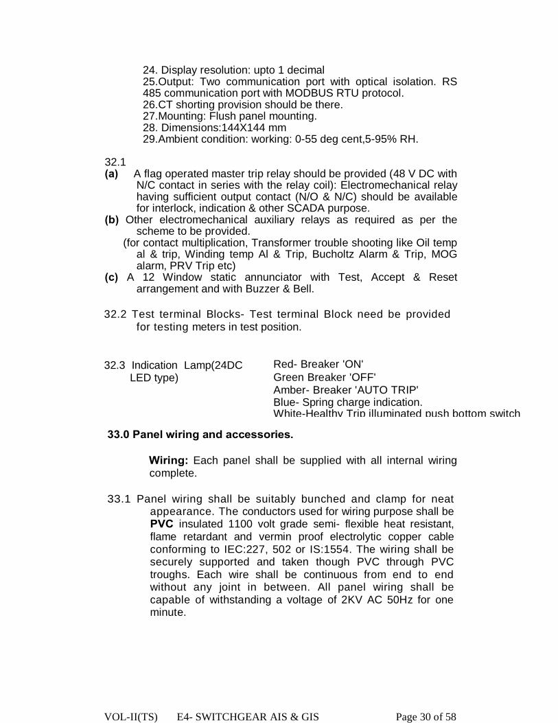
VOL-II(TS) E4- SWITCHGEAR AIS & GIS Page 30 of 58
24. Display resolution: upto 1 decimal 25.Output: Two communication port with optical isolation. RS 485 communication port with MODBUS RTU protocol. 26.CT shorting provision should be there. 27.Mounting: Flush panel mounting. 28. Dimensions:144X144 mm 29.Ambient condition: working: 0-55 deg cent,5-95% RH.
32.1 (a) A flag operated master trip relay should be provided (48 V DC with
N/C contact in series with the relay coil): Electromechanical relay having sufficient output contact (N/O & N/C) should be available for interlock, indication & other SCADA purpose.
(b) Other electromechanical auxiliary relays as required as per the scheme to be provided.
(for contact multiplication, Transformer trouble shooting like Oil temp al & trip, Winding temp Al & Trip, Bucholtz Alarm & Trip, MOG alarm, PRV Trip etc)
(c) A 12 Window static annunciator with Test, Accept & Reset arrangement and with Buzzer & Bell.
32.2 Test terminal Blocks- Test terminal Block need be provided for testing meters in test position.
32.3 Indication Lamp(24DC
LED type) Red- Breaker 'ON' Green Breaker 'OFF' Amber- Breaker 'AUTO TRIP' Blue- Spring charge indication. White-Healthy Trip illuminated push bottom switch
33.0 Panel wiring and accessories.
Wiring: Each panel shall be supplied with all internal wiring complete.
33.1 Panel wiring shall be suitably bunched and clamp for neat appearance. The conductors used for wiring purpose shall be PVC insulated 1100 volt grade semi- flexible heat resistant, flame retardant and vermin proof electrolytic copper cable conforming to IEC:227, 502 or IS:1554. The wiring shall be securely supported and taken though PVC through PVC troughs. Each wire shall be continuous from end to end without any joint in between. All panel wiring shall be capable of withstanding a voltage of 2KV AC 50Hz for one minute.
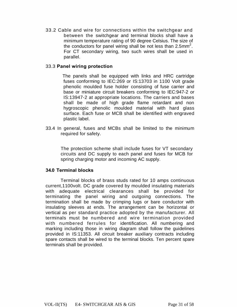
VOL-II(TS) E4- SWITCHGEAR AIS & GIS Page 31 of 58
33.2 Cable and wire for connections within the switchgear and between the switchgear and terminal blocks shall have a minimum temperature rating of 90 degree Celsius. The size of the conductors for panel wiring shall be not less than 2.5mm2. For CT secondary wiring, two such wires shall be used in parallel.
33.3 Panel wiring protection
The panels shall be equipped with links and HRC cartridge fuses conforming to IEC:269 or IS:13703 in 1100 Volt grade phenolic moulded fuse holder consisting of fuse carrier and base or miniature circuit breakers conforming to IEC:947-2 or IS:13947-2 at appropriate locations. The carriers and bases shall be made of high grade flame retardant and non hygroscopic phenolic moulded material with hard glass surface. Each fuse or MCB shall be identified with engraved plastic label.
33.4 In general, fuses and MCBs shall be limited to the minimum required for safety.
The protection scheme shall include fuses for VT secondary circuits and DC supply to each panel and fuses for MCB for spring charging motor and incoming AC supply.
34.0 Terminal blocks
Terminal blocks of brass studs rated for 10 amps continuous current,1100volt. DC grade covered by moulded insulating materials with adequate electrical clearances shall be provided for terminating the panel wiring and outgoing connections. The termination shall be made by crimping lugs or bare conductor with insulating sleeves at ends. The arrangement can be horizontal or vertical as per standard practice adopted by the manufacturer. All terminals must be numbered and wire termination provided with numbered ferrules for identification. All numbering and marking including those in wiring diagram shall follow the guidelines provided in IS:11353. All circuit breaker auxiliary contracts including spare contacts shall be wired to the terminal blocks. Ten percent spare terminals shall be provided.
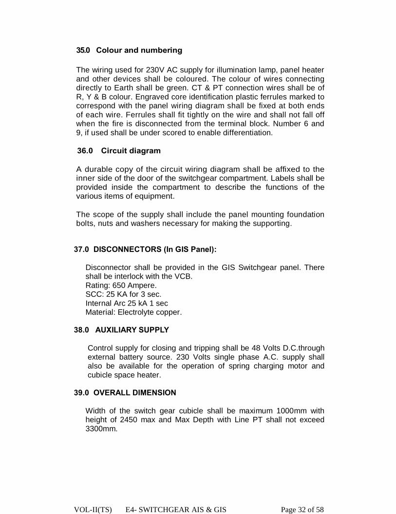
VOL-II(TS) E4- SWITCHGEAR AIS & GIS Page 32 of 58
35.0 Colour and numbering
The wiring used for 230V AC supply for illumination lamp, panel heater and other devices shall be coloured. The colour of wires connecting directly to Earth shall be green. CT & PT connection wires shall be of R, Y & B colour. Engraved core identification plastic ferrules marked to correspond with the panel wiring diagram shall be fixed at both ends of each wire. Ferrules shall fit tightly on the wire and shall not fall off when the fire is disconnected from the terminal block. Number 6 and 9, if used shall be under scored to enable differentiation.
36.0 Circuit diagram
A durable copy of the circuit wiring diagram shall be affixed to the inner side of the door of the switchgear compartment. Labels shall be provided inside the compartment to describe the functions of the various items of equipment.
The scope of the supply shall include the panel mounting foundation bolts, nuts and washers necessary for making the supporting. 37.0 DISCONNECTORS (In GIS Panel):
Disconnector shall be provided in the GIS Switchgear panel. There shall be interlock with the VCB. Rating: 650 Ampere. SCC: 25 KA for 3 sec. Internal Arc 25 kA 1 sec Material: Electrolyte copper.
38.0 AUXILIARY SUPPLY
Control supply for closing and tripping shall be 48 Volts D.C.through external battery source. 230 Volts single phase A.C. supply shall also be available for the operation of spring charging motor and cubicle space heater.
39.0 OVERALL DIMENSION
Width of the switch gear cubicle shall be maximum 1000mm with height of 2450 max and Max Depth with Line PT shall not exceed 3300mm.
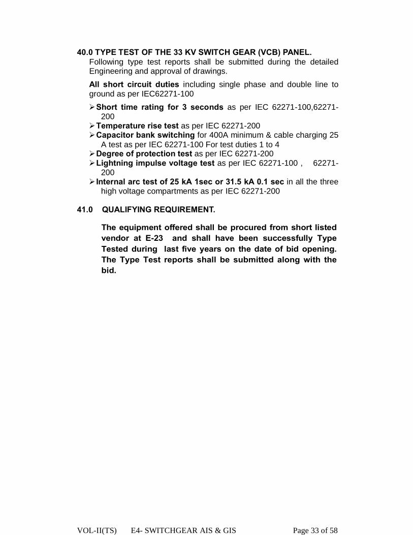
VOL-II(TS) E4- SWITCHGEAR AIS & GIS Page 33 of 58
40.0 TYPE TEST OF THE 33 KV SWITCH GEAR (VCB) PANEL. Following type test reports shall be submitted during the detailed Engineering and approval of drawings. All short circuit duties including single phase and double line to ground as per IEC62271-100 Ø Short time rating for 3 seconds as per IEC 62271-100,62271-
200 Ø Temperature rise test as per IEC 62271-200 Ø Capacitor bank switching for 400A minimum & cable charging 25
A test as per IEC 62271-100 For test duties 1 to 4 Ø Degree of protection test as per IEC 62271-200 Ø Lightning impulse voltage test as per IEC 62271-100 , 62271-
200 Ø Internal arc test of 25 kA 1sec or 31.5 kA 0.1 sec in all the three
high voltage compartments as per IEC 62271-200
41.0 QUALIFYING REQUIREMENT.
The equipment offered shall be procured from short listed vendor at E-23 and shall have been successfully Type Tested during last five years on the date of bid opening. The Type Test reports shall be submitted along with the bid.

VOL-II(TS) E4- SWITCHGEAR AIS & GIS Page 34 of 58
PART - B
TECHNICAL SPECIFICATION FOR
11KV INDOOR VACCUM CIRCUIT BREAKER

-48-
1.0 REQUIREMENTS This specification covers design, engineering, manufacture, testing, and inspection of 11 KV indoor Air Insulated Switchgear panel (provided with Vacuum circuit Breaker, CT, IVT, Disconnector etc) for use in the 33/11KV primary substations under the distribution networks. 11 KV Switchgear (Vacuum breakers, CT, IVT & Disconnector) must be type tested & the Dimension of Type Tested equipment are only be accepted. 1.1 Description of the switchgear panels for 11 KV AIS. Indoor switchgears for AIS should be provided in a cubicle, which shall be erected inside a building. Separate switchgear panels for feeder & transformer of 11 KV AIS system are to be considered. Care should be taken during manufacturing of the same as the equipment like VCB, Disconnector switches, CT & IVT are to be installed in the panel individually. Vibration is inevitable as mechanical operation for closing the VCB & disconnectors may cause problem and its performance will be affected
The circuit breakers switchgear panels to be supplied against this specification shall be required to control the LV side of 33/11 KV power transformers in the primary sub-stations and also the incoming 11KV feeders or the outgoing feeders in these sub-stations. The switchgear panels shall be suitable for 3 phase 50Hz solidly grounded neutral system and shall have normal current carrying capacity of 1250 Amp and symmetrical short circuit breaking capability as mentioned hereunder.
2 . 0 S T A N D A R D S :
Expect where modified by this specification, the circuit breakers and the accessories shall be designed, manufactured and tested in accordance with latest editions of the following standards. IEC/ISO/BS IS Subject IEC:56 IEC: 62271-100 & 200
High voltage alternating current circuit breakersgeneral Requirement.
IEC:694 IS : 12729 Common clauses of high voltage switch-gear and control gear standards (for voltage exceeding 1000 V).
IEC:60 IS : 9135 High Voltage testing techniques. I EC:427 IS:13516 Method of synthetic testing of HV .A.0 circuit breakers. IEC: 1233 HV. AC. Circuit breakers- inductive load switching. IEC: 17A/CD:474 HV. AC. Circuit breakers- capacitive switching. IEC:529 IS: 13947 Degree of protection provided by enclosure. IEC:137 IS: 2099 Insulating bushing for A.C. voltages above 1000V IEC:233 IS : 5621 Hollow insulators for use in electrical equipment & testing. IEC:273 IS: 5350 Characteristics of indoor and outdoor post insulators for IEC:815 IS: 13134 Guide for selection of insulators in respect of polluted IEC: 34 IS : 996 A.0 motors ISO:1460 IS:2629 Hot dip galvanizing
IS:2633 Method of testing uniformity of zinc coated articles. IS: 5 Colour for ready missed paints and enamels IS: 6005 Code of practice for phosphating or iron and steel. IEC: 227 IS:1554 P.V.0 Insulated cables for voltages up to and including IEC:269 IS:13703 Low voltage fuses for voltages not exceeding 1000volt. ISO:800 IS:1300 Phenolic moulding materials.
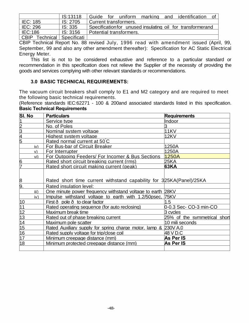
-48-
IS:13118 Guide for uniform marking and identification of IEC: 185 IS: 2705 Current transformers. IEC: 296 IS: 335 Specification for unused insulating oil for transformerand IEC:186 IS: 3156 Potential transformers. CBIP Technical Specificati
CBIP Technical Report No. 88 revised July, 1996 read with amendment issued (April, 99, September, 99 and also any other amendment thereafter): Specification for AC Static Electrical Energy Meter. This list is not to be considered exhaustive and reference to a particular standard or recommendation in this specification does not relieve the Supplier of the necessity of providing the goods and services complying with other relevant standards or recommendations.
3.0 BASIC TECHNICAL REQUIREMENTS:
The vacuum circuit breakers shall comply to E1 and M2 category and are required to meet the following basic technical requirements. (Reference standards IEC:62271 - 100 & 200and associated standards listed in this specification. Basic Technical Requirements SI. No Particulars Requirements 1 Service type Indoor 2 No. of Poles 3 3 Nominal system voltage 11KV 4 Highest system voltage 12KV 5 Rated normal current at 50°C
iv) For Bus-bar of Circuit Breaker 1250A v) For Interrupter 1250A vi) For Outgoing Feeders/ For Incomer & Bus Sections 1250A
6 Rated short circuit breaking current (rms) 25KA 7 Rated short circuit making current (peak) 63KA
8 Rated short time current withstand capability for 3 sec.
25KA(Panel)/25KA (Interrupter) 9. Rated insulation level:
iii) One minute power frequency withstand voltage to earth 28KV iv) Impulse withstand voltage to earth with 1.2/50psec, 75KV
10 First — pole — to clear factor 1.5 11 Rated operating sequence (for auto reclosing) 0-0.3 Sec- CO-3 min-CO 12 Maximum break time 3 cycles 13 Rated out of phase breaking current 25% of the symmetrical short14 Maximum pole scatter 10 mili seconds 15 Rated Auxiliary supply for spring charge motor, lamp & 230V A.0 16 Rated supply voltage for trip/close coil 48 V D.C 17 Minimum creepage distance (mm) As Per IS 18 Minimum protected creepage distance (mm) As Per IS
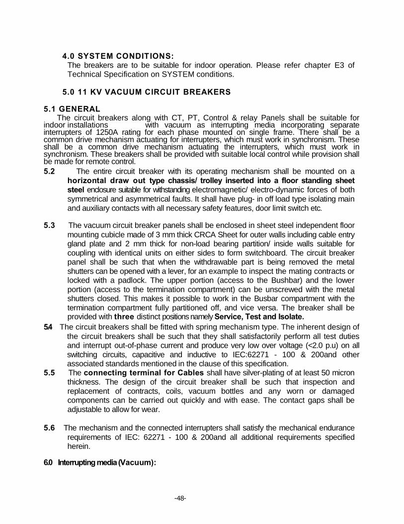
-48-
4.0 SYSTEM CONDITIONS: The breakers are to be suitable for indoor operation. Please refer chapter E3 of Technical Specification on SYSTEM conditions.
5.0 11 KV VACUUM CIRCUIT BREAKERS 5.1 GENERAL The circuit breakers along with CT, PT, Control & relay Panels shall be suitable for indoor installations with vacuum as interrupting media incorporating separate interrupters of 1250A rating for each phase mounted on single frame. There shall be a common drive mechanism actuating for interrupters, which must work in synchronism. These shall be a common drive mechanism actuating the interrupters, which must work in synchronism. These breakers shall be provided with suitable local control while provision shall be made for remote control. 5.2 The entire circuit breaker with its operating mechanism shall be mounted on a
horizontal draw out type chassis/ trolley inserted into a floor standing sheet steel enclosure suitable for withstanding electromagnetic/ electro-dynamic forces of both symmetrical and asymmetrical faults. It shall have plug- in off load type isolating main and auxiliary contacts with all necessary safety features, door limit switch etc.
5.3 The vacuum circuit breaker panels shall be enclosed in sheet steel independent floor mounting cubicle made of 3 mm thick CRCA Sheet for outer walls including cable entry gland plate and 2 mm thick for non-load bearing partition/ inside walls suitable for coupling with identical units on either sides to form switchboard. The circuit breaker panel shall be such that when the withdrawable part is being removed the metal shutters can be opened with a lever, for an example to inspect the mating contracts or locked with a padlock. The upper portion (access to the Bushbar) and the lower portion (access to the termination compartment) can be unscrewed with the metal shutters closed. This makes it possible to work in the Busbar compartment with the termination compartment fully partitioned off, and vice versa. The breaker shall be provided with three distinct positions namely Service, Test and Isolate.
5.4 The circuit breakers shall be fitted with spring mechanism type. The inherent design of the circuit breakers shall be such that they shall satisfactorily perform all test duties and interrupt out-of-phase current and produce very low over voltage (<2.0 p.u) on all switching circuits, capacitive and inductive to IEC:62271 - 100 & 200and other associated standards mentioned in the clause of this specification.
5.5 The connecting terminal for Cables shall have silver-plating of at least 50 micron thickness. The design of the circuit breaker shall be such that inspection and replacement of contracts, coils, vacuum bottles and any worn or damaged components can be carried out quickly and with ease. The contact gaps shall be adjustable to allow for wear.
5.6 The mechanism and the connected interrupters shall satisfy the mechanical endurance requirements of IEC: 62271 - 100 & 200and all additional requirements specified herein.
6.0 Interrupting media (Vacuum):

-48-
6.1 In vacuum circuit breakers, facilities shall be provided for monitoring the contract erosion and any change in contact gap. The vacuum bottles shall be easily replaceable on site and the mechanism shall be conveniently adjustable to permit resetting the contact gap. The current rating of the vacuum interrupters shall be 1250Am p.
6.2 The vacuum circuit breaker poles shall be sealed to prevent contamination of the spaces surrounding the interrupters. The bidder shall demonstrate how this is achieved by supplying technical details with the bid.
7. 0 Auxiliary contacts
7.1 Auxiliary contacts (6 N.O. +6 N.C.) of 48 Volt D.C grade and 10 amps DC rating shall be provided in each circuit breaker.
8.0 Indication
8.1 A mechanically operated circuit breaker position indicator of non-corroding
material shall be provided in a location visible from the operating side of the breaker without the necessity to open the mechanism door. The word 'OFF' in white letter on green background shall be used to indicate that the breaker is in the opening position and the word 'ON' in white letters on a red background to indicate that the breaker is in the closed position. The drive for the device shall be positive in both directions and provision shall be made for local and remote electrical indication.
8.2 Indication of spring charging condition shall be provided as mentioned in this Specification. Mechanical counters to record the number of closing operations shall be provided for each circuit breaker mechanism.
9.0 Operation and controls
9.1 The breaker shall normally be operated by electrical control with electrical tripping by 2 Nos.shunt trip coil. Provision shall be made for local electrical operation and mechanical operation.
9.2 The following facilities shall be provided in the circuit breaker local control cabinet:
• ON/NEUTRAL/ OFF control switch or ON and OFF push buttons. The push buttons shall be momentary contract type with rear terminal connections. The close push button shall be of green colour and the open push button red colour.
• MECHANICAL EMERGENCY TRIP DEVICE: suitable for manual operation in the event of failure of electrical supplies. The device shall be accessible without opening any access doors and distinctly

-48-
labeled. It shall be shrouded and protected against inadvertent operation.
• Means shall be provided for manual operation of these circuit breakers during failure of auxiliary power in addition to electrical operation.
9.2 Means shall be provided to prevent the mechanism from responding to a close signal when the trip coil is energized or to reclosing from a sustained close signal either opening due to a trip signal or failure to hold in the closed position.
9.3 The circuit breaker shall be able to perform 10,000 operating cycles at no load in accordance with IEC:17A/474/CD for circuit breakers for auto reclosing duties.
10.0 CURRENT TRANSFORMERS
10.1 Current transformers, three per circuit breaker, shall be of indoor, single phase,resin cast and shall comply with IEC:185 and IS:2705, suitable for operation in hot and humid atmospheric conditions described in service condition. They shall be mounted inside the panel.
10.2 Core
10.2.1 High grad non- ageing cold rolled grain oriented (CRGO M4 or better grade) silicon steel of low hysteresis loss and permeability shall be used for the core so as to ensure specified accuracy at both normal and over currents. The flux density shall be limited to ensure that there is no saturation during normal service.
10.2.2 The instrument security factor of the core shall be low enough so as not to cause damage to the instruments in the event of maximum short circuit current.
10.3 Windings
10.3.1 The secondary windings shall be made of electrolytic copper with suitable insulation. The conductor shall be of adequate cross- section so as to limit the temperature rise even during short circuit conditions. The insulation of windings and connections shall be free from composition liable to soften, coze, shrink or collapse during service.
10.3.2 Polarity shall be indelibly marked on each current transformer and at the lead and termination at associated terminal blocks. CTs with multi ratio winding shall be clearly tabulated to show the connections required for different ratios. Similar numbers shall be marked on terminal block arrangement and wiring diagram. Apart from the above marking and those to be provided as per IEC 185 or IS 2705, other markings shall be provided in consultation with owner.
10.3.3 The continuous current rating of the primary winding shall be one hundred and twenty percent of the normal rated current.
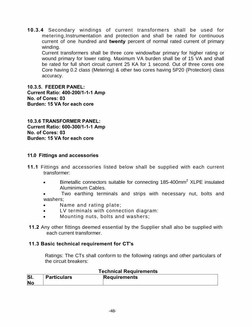
-48-
10.3.4 Secondary windings of current transformers shall be used for metering,Instrumentation and protection and shall be rated for continuous current of one hundred and twenty percent of normal rated current of primary winding. Current transformers shall be three core window/bar primary for higher rating or wound primary for lower rating. Maximum VA burden shall be of 15 VA and shall be rated for full short circuit current 25 KA for 1 second. Out of three cores one Core having 0.2 class (Metering) & other two cores having 5P20 (Protection) class accuracy.
10.3.5. FEEDER PANEL: Current Ratio: 400-200/1-1-1 Amp No. of Cores: 03 Burden: 15 VA for each core 10.3.6 TRANSFORMER PANEL: Current Ratio: 600-300/1-1-1 Amp No. of Cores: 03 Burden: 15 VA for each core 11.0 Fittings and accessories
11.1 Fittings and accessories listed below shall be supplied with each current transformer:
• Bimetallic connectors suitable for connecting 185-400mm2 XLPE insulated Aluminimum Cables.
• Two earthing terminals and strips with necessary nut, bolts and washers; • Name and rat ing p late; • LV terminals with connection diagram: • Mounting nuts, bol ts and washers;
11.2 Any other fittings deemed essential by the Supplier shall also be supplied with each current transformer.
11.3 Basic technical requirement for CT's
Ratings: The CTs shall conform to the following ratings and other particulars of the circuit breakers:
Technical Requirements SI. No
Particulars Requirements

-48-
1 Function To control 11 KV Feeder & LV side of 33/11KV power transformers of ratings between 3.15MVA to 12.5MVA
2 Requirement The CTs in the 11 KV Indoor VCB switchgear panel should have three cores as follows.
3 Transformation Ratio Category- A (For TFR) 600-300/1-1-1-A
Category- B (For Feeder)
4 Rated Burden (VA) Core:1: 15 VA , Core:2: 15 VA, Core:3:15 VA
Core:1: 15 VA , Core:2: 15 VA, Core:3:15 VA
5 Class of Accuracy Core:1: 0.2 , Core:2: 5P20, Core:3: 5P20
Core:1: 0.2 , Core:2: 5P20,
Core:3: 5P20
6 Instrument Security Factor
Core- 1:- <5
Core- 1:- <5
7 Purpose Core:1: Metering , Core:2: Differential, Core:3:O/C& E/F & REF
Core:1: Metering , Core:2: Spare Core:3:O/C& E/F & REF
8 Rated/Highest syatem Voltage 11/12 KV
9 Short Time Rating 25 KA rms for 3 seconds
10 Power frequency 1 min voltage withstand level/Insulation Level: -Impulse Voltage1.2/50ps wave
28 KV/75KV
12.0 Tests
12.1 The CTs shall be tested in accordance with the requirements of the type tests and routine tests as per the latest issues IEC:185 or IS:2705.
The tests to be conducted shall include: 12.2 Type Tests:
• L ightning impulse vol tage: • Power frequency wet withstand voltage; • Temperature rise; • Short time current; • Composite error; • Accuracy test (for measuring core); • Instrument security current (for measuring core);
12.3 Routine tests
• Verification of terminal marking and polarity; • Power frequency dry withstand test on primary windings

-48-
• Power frequency dry withstand test on secondary windings • Power frequency dry withstand test between sections; • Over voltage inter-turn test; • Composite error; • Tu rn ra t i o ; • Accuracy test (for measuring core); • Current error and phase displacement (for protection core); • Knee point voltage and magnetizing current test (for PS class); • Secondary winding resistance (for PS class).
13.0 POTENTIAL TRANSFORMER
13.1 BASIC TECHNICAL REQIREMENTS
The 11 KV Indoor voltage transformers are required to meet the following basic technical requirements (Reference standards: IEC:186, IS:3156 and associated standards listed in the specification):
SI. No
Particulars Requirements
1 Type Single phase 2 Nominal system voltage, phase to phase 11 KV 3 Application Instrumentation, Metering and
Protection 4 Number of secondary windings 1 5 Rated normal burden* 50VA/15VA 6 Rated primary voltage 11000/√3 7 Rated secondary voltage 110V/√3-110V/√3 8 Class of accuracy 0.2/3P 9 Rated insulation level: (Primary winding)
(Phase to earth)
iii) One minute power frequency withstand voltage to earth (wet and dry) rms
28KV iv) Impulse withstand voltage to earth with
1.2/50 ilsec wave of +ve and —ve polarity 75KV
10 One minute power frequency withstand voltage of secondary winding (rms)
Between phase to earth 3KV Between sections 3KV
11 Rated voltage factor Continuous 1.2 For 30 seconds 1.5
* The burden indicated is the minimum acceptable to the Employer. The Contractor shall ensure that the rated outputs of the voltage transformers are adequate to meet at least 120 percent of the connected load (burden).
13.2 GENERAL

-48-
The voltage transformers to be supplied under this specification shall be of Indoor, single phase Polycrate complying with IEC:185 and IS:3156 suitable for operation in hot and humid atmospheric conditions described in this document.
13.3 Duty requirement
13.3.1 11 KV Voltage transformer for all the indicating instruments and measuring meters in the primary substation on 11KV side. It shall be of indoor, 1-Phase or 3- phase Polycrate type.
13.4 Core
13.4.1 High grade non-ageing cold rolled grain oriented (CRGO-M4 or better) silicone steel of low hysteresis loss and permeability shall be used for core so as to ensure accuracy at both normal and or over Voltages. The flux density shall be limited to 1.6 Tesla at normal voltage and frequency. There shall be no saturation at any stage during operation.
13.4.2 The instrument security factor of the core shall be low enough so as not to cause damage to the instruments in the event of maximum short circuit current or over voltages.
13.5 Windings
13.5.1 The primary and secondary windings shall be electrolytic copper of high purity and conductivity and covered with double paper insulation. The conductor shall be of adequate cross-section so as to limit the temperature rise even during maximum over voltages.
13.5.2 The insulation of windings and connections shall be free from composition liable to soften, ooze, shrink or collapse during service.
13.5.3 The secondary windings of the voltage transformers shall also be suitable for continuous over voltage corresponding to the maximum system voltage at the primary winding. The winding supports shall be suitably reinforced to withstand normal handling and the thermal and dynamic stresses during operation without damage.
13.5.4 The voltage transformer secondary circuits will be taken out to form the star point and earthed at one point outside the voltage transformers.
13.5.5 Both primary and secondary winding terminals shall be clearly and indelibly marked to show polarity in accordance with IEC:186. The connections required for different secondary windings in case of multi-winding voltage transformers shall be clearly indicated in terminal blocks and the wiring diagrams.
14.0 Fitting and Accessories

-48-
14.1 Fittings and accessories listed below shall be supplied with each voltage transformer:
• H V t e r mi n a l s ; • Two earthing terminals with necessary nuts, bolts and washers; • Name and ra t ing p l a te ; • Secondary terminal box with LV terminal connections; • Mounting nuts, bol ts and washers; • L.V HRC cartridge fuses for the protection of secondary winding; • HV HRC cartridge fuses for the protection of Primary winding
14.2 Any other fitting deemed essential by the contractor shall also be supplied along with each voltage transformer:
14.3 The name and rating plate shall contain all the particulars as provided in IEC:186 and also the name of the employer and year of manufacture. They shall comply with the clause termed label in this specification.
15.0 Fuse protection The Primary winding shall be protected by HRC Fuses in suitable holder designed by the manufacturers.
15.1 The secondary windings shall be protected by HRC cartridge fuses in fuse holder consisting of carriers and bases. The carriers and bases shall be of high grade flame retarding and non-hygroscopic moulded insulating materials with hard glass surface. Each fuse shall be identified with engraved plastic label.
16.0 Circuit diagram
16.1 A durable copy of the circuit wiring diagram shall be affixed to the inner side of the terminal box cover. Labels shall be provided inside the cover to describe the functions of various items of equipment.
17.0 TERMINATION
17.1 The equipment shall be supplied with HV electrical connection terminals of a size and rating appropriate for all the duties, including overload duty specified for the equipment. The terminals shall be of the bi-metallic type.
18.0 EARTHING TERMINAL
18.1 Two earthling terminals complete with necessary hardware shall be provided on each voltage transformer for connection to earth continuity conductors of the Employer. They shall be of electroplated brass and of adequate size to carry the earth fault current.
-48-
18.2 The earthing terminals shall be identified by means of appropriate symbol marked in a legible and indelible manner adjacent to the terminals.
19.0 TEST AND INSPECTIONS
19.1 The voltage transformers shall be tested in accordance with the requirements of the type tests and routine tests as provided in the latest issues of IEC:186 or IS:3516.
The tests to be conducted shall include; 19.2 Type tests:
• Lightning impulse vol tage test ; • High voltage power frequency wet withstand voltage; • Tempera tu re r i se tes t ; • Short circuit withstand capability test;
• Determination of limits of voltage error and phase displacement.
19.3 Routine tests: • Verification of terminal marking and polarity; • Power frequency withstand tests on primary winding; • Power frequency dry withstand tests on secondary winding; • Power frequency withstand tests between sections; • Determination of limits of voltage errors and phase displacement; • Insulating Resistance measurement. • Partial discharge measurement.
19.4 TEMPERATURE RISE
The temperature rise of any part of the voltage transformer under continuous operating and exposed in the direct rays of the sun shall not exceed the permissible limits as provided in IEC publication 186 or IS:3156. These shall not be exceeded when corrected for the difference between the ambinent temperature at site and the ambient temperature specified in the standard. The correction proposed shall be stated in the bid.
20.0 PROTECTIVE RELAY & CONTROL PANEL
20.1 The CR Panel (Instrument Chamber) should be mounted on top of the VCB Panel.
Control panel (inbuilt) with protective relay and meter shall be provided by the supplier suitable for above breakers. The equipment shall have protection scheme with the following relays: (i) Triple pole IDMTL type combined over current (3Nos) & Earth fault
(1No) relay (Draw out type) preferably Communicable numerical relay of reputed make with supporting Protocol IEC:61850and that should be type tested with IEC protocol 61850 . The detailed Specification are as indicated in 33 KV indoor switchgear pane
-48-
l(Sl No. 14) 21.0 MULTIFUNCTION METER GENERAL 1. Each bay should be provided with a multifunction meter having following features:- 2. Features: By level monitoring of all electrical parameters of V,I,⏀,cos⏀,Hz,KVA,KVAR,KW & KWH.True RMS measurement 3. Accuracy: 0.2. 4. User selectable display ranges. (CT/PT). 5. Auto scrolling/Manual display 6. RS 485 communication port with MODBUS RTU protocol. Compatible for data logging & SCADA application. 7. Inbuilt Real time clock with calendar. 8. 3phase,4 wire,3 element or as per requirement.(to be decided during detail Engineering). 9. Quadrant of operation: 04 Quadrant. 10. Display: Bright red 7-segment LED display. 11. HMI: Through Front panel tactile keys. 12. Indication: Phase voltage, Phase current ,Line voltage, Frequency, Power factor, KVA,KVAR,KW,KVAH,KVARH,KWH. 13. Voltage input: 63.5/110V 14. Current Input: 1 A 15. Auxiliary supply: 85-250 V AC or 48 V DC 16. VA burden: 15VA 17. Frequency Range: 45 to 55 Hz 18. Power factor range: 0.1 lag -1 -0.1 lead 19. Over voltage: 130% continuously & 200% for 30 sec 20. Over current: 2 times continuous, 20 times for 1 sec. 21. Response time: 200 ms 22. Class of accuracy: 0.2s as per IEC 60687, IS 14697 23. Complies to EMI: IEC 61000-4-5,3,4 24. Display resolution: upto 1 decimal 25. Output: Two communication port with optical isolation. RS 485 communication port with MODBUS RTU protocol. 26. CT shorting provision should be there. 27. Mounting: Flush panel mounting. 28. Dimensions:144X144 mm 29. Ambient condition: working: 0-55 deg cent,5-95% RH. 22.1 (a) A flag operated master trip relay should be provided (48 V DC with N/C contact in series with the relay coil): Electromechanical relay having sufficient output contact (N/O & N/C) should be available for interlock, indication & other SCADA purpose. (b) Other electromechanical auxiliary relays as required as per the scheme to be provided. (for contact multiplication, Transformer trouble shooting like Oil temp al & trip, Winding temp Al & Trip, Bucholtz Alarm & Trip, MOG alarm, PRV Trip etc) (c) A 12 Window static annunciator with Test, Accept & Reset arrangement and with Buzzer & Bell.
(ii) Test terminal Blocks- Test terminal Block need be provided for testing
-48-
meters in test position. ii) Indication
Lamp(24DC LED type)
Red- Breaker 'ON' Green Breaker 'OFF' Amber- Breaker 'AUTO TRIP' Blue- Spring charge indication. White-Healthy Trip illuminated push bottom switch
22.2 In Built Control- Relay Panel in the In Door VCB (Mounted on the Top of VCB Panel)
22.0 Panel wiring and accessories.
22.1 Wiring
Each panel shall be supplied with all internal wiring complete.
22.2 Panel wiring shall be suitably bunched and clamp for neat appearance. The conductors used for wiring purpose shall be PVC insulated 1100 volt grade semi- flexible heat resistant, flame retardant and vermin proof electrolytic copper cable conforming to IEC:227, 502 or IS:1554. The wiring shall be securely supported and taken though PVC through PVC troughs. Each wire shall be continuous from end to end without any joint in between. All panel wiring shall be capable of withstanding a voltage of 2KV AC 50Hz for one minute.
22.3 Cable and wire for connections within the switchgear and between the switchgear and terminal blocks shall have a minimum temperature rating of 90 degree Celsius. The size of the conductors for panel wiring shall be not less than 2.5mm2. For CT secondary wiring, two such wires shall be used in parallel.
22.4 Panel wiring protection The panels shall be equipped with links and HRC cartridge fuses conforming to IEC:269 or IS:13703 in 1100 Volt grade phenolic moulded fuse holder consisting of fuse carrier and base or miniature circuit breakers conforming to IEC:947-2 or IS:13947-2 at appropriate locations. The carriers and bases shall be made of high grade flame retardant and non hygroscopic phenolic moulded material with hard glass surface. Each fuse or MCB shall be identified with engraved plastic label.
22.5 In general, fuses and MCBs shall be limited to the minimum required for safety.
The protection scheme shall include fuses for VT secondary circuits and DC supply to each panel and fuses for MCB for spring charging motor and incoming AC supply.
23.0 Terminal blocks
-48-
23.1Terminal blocks of brass studs rated for 10 amps continuous current, 1100 volt DC grade covered by moulded insulating materials with adequate electrical clearances shall be provided for terminating the panel wiring and outgoing connections. The termination shall be made by crimping lugs or bare conductor with insulating sleeves at ends. The arrangement can be horizontal or vertical as per standard practice adopted by the manufacturer. All terminals must be numbered and wire termination provided with numbered ferrules for identification. All numbering and marking including those in wiring diagram shall follow the guidelines provided in IS:11353. All circuit breaker auxiliary contracts including spare contacts shall be wired to the terminal blocks. Ten percent spare terminals shall be provided.
24.0 Colour and numbering
The wiring used for 230V AC supply for illumination lamp, panel heater and other devices shall be coloured. The colour of wires connecting directly to Earth shall be green. CT & PT connection wires shall be of R, Y & B colour.
24.1 Engraved core identification plastic ferrules marked to correspond with the panel wiring diagram shall be fixed at both ends of each wire. Ferrules shall fit tightly on the wire and shall not fall off when the fire is disconnected from the terminal block. Number 6 and 9, if used shall be under scored to enable differentiation.
25.0 Circuit diagram
26.1 A durable copy of the circuit wiring diagram shall be affixed to the inner side of the door of the switchgear compartment. Labels shall be provided inside the compartment to describe the functions of the various items of equipment.
26.2 The scope of the supply shall include the panel mounting foundation bolts, nuts and washers necessary for making the supporting.
26.0 OPERATING MECHANISM
26.1 General 26.1.1 The operating mechanism of the circuit breaker shall be motor wound
spring charged type. It shall be electrically and mechanically trip free with anti pumping device (as per IEC:694 definition). All working parts in the mechanism shall be of corrosion resistant material. Self lubricating, wearing resistant bearings shall be provided in the mechanism.
26.1.2 The mechanism shall fully close the circuit breaker and sustain it in the closed position against the forces of the rated making current and shall fully open the circuit breaker without undue contact bounce at a speed commensurate with that shown by tests to be necessary to achieve the rated breaking capacity in accordance with IEC:56 or IS:13118. The
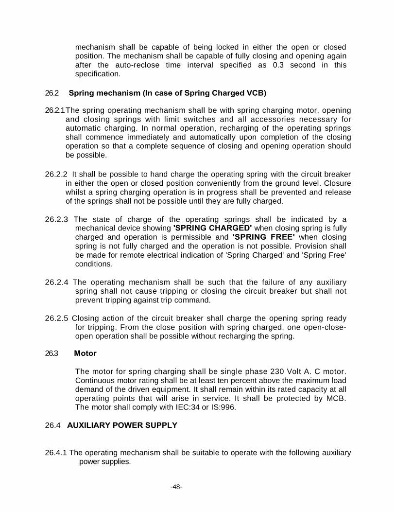
-48-
mechanism shall be capable of being locked in either the open or closed position. The mechanism shall be capable of fully closing and opening again after the auto-reclose time interval specified as 0.3 second in this specification.
26.2 Spring mechanism (In case of Spring Charged VCB)
26.2.1 The spring operating mechanism shall be with spring charging motor, opening and closing springs with limit switches and all accessories necessary for automatic charging. In normal operation, recharging of the operating springs shall commence immediately and automatically upon completion of the closing operation so that a complete sequence of closing and opening operation should be possible.
26.2.2 It shall be possible to hand charge the operating spring with the circuit breaker in either the open or closed position conveniently from the ground level. Closure whilst a spring charging operation is in progress shall be prevented and release of the springs shall not be possible until they are fully charged.
26.2.3 The state of charge of the operating springs shall be indicated by a mechanical device showing 'SPRING CHARGED' when closing spring is fully charged and operation is permissible and 'SPRING FREE' when closing spring is not fully charged and the operation is not possible. Provision shall be made for remote electrical indication of 'Spring Charged' and 'Spring Free' conditions.
26.2.4 The operating mechanism shall be such that the failure of any auxiliary spring shall not cause tripping or closing the circuit breaker but shall not prevent tripping against trip command.
26.2.5 Closing action of the circuit breaker shall charge the opening spring ready for tripping. From the close position with spring charged, one open-close-open operation shall be possible without recharging the spring.
26.3 Motor
The motor for spring charging shall be single phase 230 Volt A. C motor. Continuous motor rating shall be at least ten percent above the maximum load demand of the driven equipment. It shall remain within its rated capacity at all operating points that will arise in service. It shall be protected by MCB. The motor shall comply with IEC:34 or IS:996.
26.4 AUXILIARY POWER SUPPLY
26.4.1 The operating mechanism shall be suitable to operate with the following auxiliary
power supplies.

-48-
a) 230V,50Hz Single phase For spring charging motor AC A
b) DC supply 24 Volts- For close and open coils.
26.5 The DC supply shall be from Battery Bank.
27.6 The mechanism shall be designed to operate satisfactorily despite fluctuations of auxiliary power supplies as under:
AC supply: Voltage From 115% to 85% of normal voltage Frequency variation From 106% to 94% DC supply: Voltage From 115% to 85%
26.7 Temperature Rise test:
The temperature rise and the maximum temperature of any part of the circuit breaker under continuous load condition and exposed in the direct rays of the sun shall not exceed the permissible limits as provided in Table V of IEC publication 694 or table 4 of IS:12729. These limits shall not be exceeded when corrected for the difference between the ambient temperature at site and the ambient temperature specified in the standard. The correction proposed shall be stated in the tender.
27.0 TESTS
27.1 Type and routine tests
The circuit breakers shall be subjected to routine and type tests in accordance with the standards listed in this specification including the following IEC and IS standards with the latest amendments:
• Ci rcui t breakerIEC:62271 - 100 & 200and relevant other standards • Porcelain insulator IEC:233 and IS:5621 and relevant other standards The tests shall include but not limited to the following: The copies of Type Test reports shall be attached with the Offer.
27.2 Short circuit tests The circuit breaker shall satisfactorily perform the out of phase and short circuit duties speci f ied in IEC:62271-100 & 200, IEC:17A(Sect .)438 and IEC:17A/CD/474 and IS:13516.
The circuit breaker shall be capable of performing at least twenty five (25) open operations at the rated short circuit current before maintenance or inspection is required.

-48-
27.3 Dielectric tests
At zero gauge loss of vacuum inside the interrupter chamber, the open contracts shall withstand continuously, the rated phase to ground voltage and it shall be possible to break normal current in these conditions. During the dielectric type tests, no flashover external or internal shall be acceptable.
The circuit breakers shall be subjected to a power frequency AC voltage test for one minute in dry and wet conditions and there shall be no external flash over to earth.
27.4 Mechanical endurance
In addition to the requirements of IEC:56, an extended mechanical endurance test is required to show that the circuit breaker is capable of at least 10,000 operations at no load in accordance with IEC:17A/474/CD. Between the specified test series in IEC:17A/474/CD, some maintenance such as lubrication and mechanical adjustment is allowed and shall be performed in accordance with manufacturer's instructions. Change of contracts is not permitted.
27.5 Duty requirement tests
Apart from auto-reclosing and the other duties mentioned above, the breakers shall be able to perform the following duties for which type tests are to be conducted as per IEC:56 or IS:13118. 1. Breaking the steady and the transient magnetising current of the transformer. 2. Breaking 25% of rated fault current at twice the rated voltage as per IEC/IS. 3. Cable charging breaking current. 4. Single capacitor bank breaking current. 5. Capacitor bank in rush making current.
Test for the resistance of the main circuit shall also be conducted.
27.6 Temperature rise test
Temperature rise test is to be conducted on the circuit breaker and the accessories in accordance with IEC:62271-100 & 200. The temperature rise shall be limited as per this specification.
28.0 PERFORMANCE REQUIREMENTS The supplier shall declare the circuit breaker opening and closing times at 120 percent, 100 percent and 70 per cent of the rated voltage of the opening and closing devices when measured at the terminals of the trip
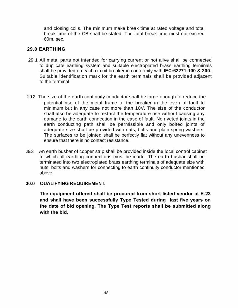
-48-
and closing coils. The minimum make break time at rated voltage and total break time of the CB shall be stated. The total break time must not exceed 60m. sec.
29.0 EARTHING
29.1 All metal parts not intended for carrying current or not alive shall be connected to duplicate earthing system and suitable electroplated brass earthing terminals shall be provided on each circuit breaker in conformity with IEC:62271-100 & 200. Suitable identification mark for the earth terminals shall be provided adjacent to the terminal.
29.2 The size of the earth continuity conductor shall be large enough to reduce the potential rise of the metal frame of the breaker in the even of fault to minimum but in any case not more than 10V. The size of the conductor shall also be adequate to restrict the temperature rise without causing any damage to the earth connection in the case of fault. No riveted joints in the earth conducting path shall be permissible and only bolted joints of adequate size shall be provided with nuts, bolts and plain spring washers. The surfaces to be jointed shall be perfectly flat without any unevenness to ensure that there is no contact resistance.
29.3 An earth busbar of copper strip shall be provided inside the local control cabinet to which all earthing connections must be made. The earth busbar shall be terminated into two electroplated brass earthing terminals of adequate size with nuts, bolts and washers for connecting to earth continuity conductor mentioned above.
30.0 QUALIFYING REQUIREMENT.
The equipment offered shall be procured from short listed vendor at E-23 and shall have been successfully Type Tested during last five years on the date of bid opening. The Type Test reports shall be submitted along with the bid.

-48-
PART – C
SPECIFICATION FOR OUTDOOR containiser sub station (E-HOUSE)
1.0 Scope : The containiser substation (Out Door E-House) will have all equipment of Indoor GIS subastaion in an portable E-House. However the Transformer, Surge Arrester, out door isolators and other take off arrangements will be be as per the technical specifications of AIS/GIS sub stations mentioned elsewhere in this specification. 2.0 Enclosure rating and design The environment which the machine will be operating will be extreme in term of temperature, humidity, corrosion and dust. Ambient temperature for design and manufacturer of enclosure shall be taken as 45 deg. C. Particular attention shall be given to the mounting of the switchboards and control equipment to ensure that they are not subjected to vibration. Physical access to all equipment shall be possible for maintenance purpose. The switchboard and control equipment housings which shall be located within on-board protected enclosures such as switch rooms and operator’s cabins shall be manufactured to IP 55.
2.0 Electrical Room (E-House)
2.1 General description The E-room shall accommodate 33 kV and 11 kV Switchgear panels containing VCB (630A), CT (630A), disconnector (630A), IVT, bus bar 800A inside GIS chamber and Battery and Battery Charger, ACDB, DCDB , RTU etc. The E-room shall be pre-assembled and pre-wired before transporting to site. Remarks to be considered:
• Dynamic or Static condition: Static • Lifting lugs should be designed to carry of the weight of the E house including all the electrical panel boards. • E House should be closed type, weather proof and made of steel construction. • Design: to with stand heavy monsoon, heavy rain and heavy wind condition. • Doors should be equipped with hydraulic door closer. • Each door has to be fitted internally with "panic” bar exit handles and externally with key lockable handles. • Door shall be provided with heavy-duty latches, hinges, door stop and pad

-48-
lock. • Doors should be provided with canopy with necessary rubber gas cutter to prevent the entry of water. • The RTU rooms shall be air-conditioned to maintain an air temperature less than 27°C. Rest E-house shall have normal ventilations. Necessary air conditioners are to be included in the scope of supply. • Safety notices and electric shock treatment codes (in English language and Local language) shall be provided on the inside of the switch room mounted adjacent to each door.
• All cable entries to electrical room shall be from bottom.
The room shall be of adequate size to meet the requirements and to provide good access to all equipment for maintenance or disassembly. Rubber insulating carpet in front of Electrical Panels shall be provided. The electrical room and the transformer room shall have False flooring arrangement.
3.0 Construction Materials
* Steel: load bearing members : IS 10748; Grade IV * Structural Steel: IS 2062. * Side-end walls & roof panels : IS 2062. * Square/Rectangular hollow sections: JIS STKR-41 / IS 1161 * Paint: To suit Hilly & Industrial climate. * Corner Fittings: Dimension as per ISO 1161 - 1984 (E)
3.1 Welding The Shell of the E house shall be of all weld construction. All the external welding shall be continuous, uniform and of full penetration. 3.2 Shell
The outer shell of the E house shall be manufactured with atmospheric corrosion resistant steel. The main load bearing members such as posts, base members, bottom and top side rails, end rails headers are pressed formed profiles of appropriate geometry. Thickness of such profile shal l vary from 3.2mm to 6.0 mm of grade IS 10748, Grade -IV. Corner fittings (dimensions as per ISO 1161) shall be provided at all eight corners. Adequate number of doors with reinforced framework and locking device shall be provided as per requirement. The door h a s to be effectively sealed against water ingress in closed condition. The shell structure is to be rigid enough to withstand rough handling rigorous transportation hazards etc. and able to stand flexing/distortion even when placed on uneven ground.
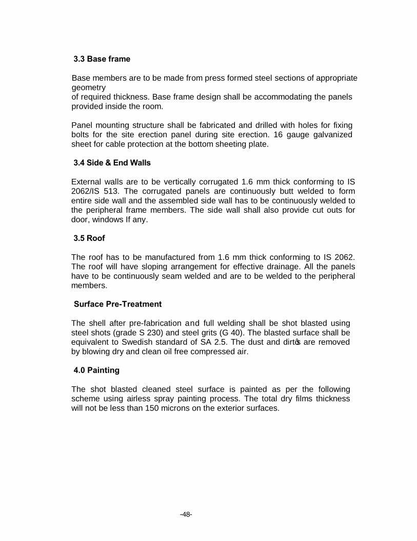
-48-
3.3 Base frame Base members are to be made from press formed steel sections of appropriate geometry of required thickness. Base frame design shall be accommodating the panels provided inside the room. Panel mounting structure shall be fabricated and drilled with holes for fixing bolts for the site erection panel during site erection. 16 gauge galvanized sheet for cable protection at the bottom sheeting plate. 3.4 Side & End Walls
External walls are to be vertically corrugated 1.6 mm thick conforming to IS 2062/IS 513. The corrugated panels are continuously butt welded to form entire side wall and the assembled side wall has to be continuously welded to the peripheral frame members. The side wall shall also provide cut outs for door, windows If any. 3.5 Roof
The roof has to be manufactured from 1.6 mm thick conforming to IS 2062. The roof will have sloping arrangement for effective drainage. All the panels have to be continuously seam welded and are to be welded to the peripheral members. Surface Pre-Treatment
The shell after pre-fabrication and full welding shall be shot blasted using steel shots (grade S 230) and steel grits (G 40). The blasted surface shall be equivalent to Swedish standard of SA 2.5. The dust and dirt’s are removed by blowing dry and clean oil free compressed air. 4.0 Painting
The shot blasted cleaned steel surface is painted as per the following scheme using airless spray painting process. The total dry films thickness will not be less than 150 microns on the exterior surfaces.
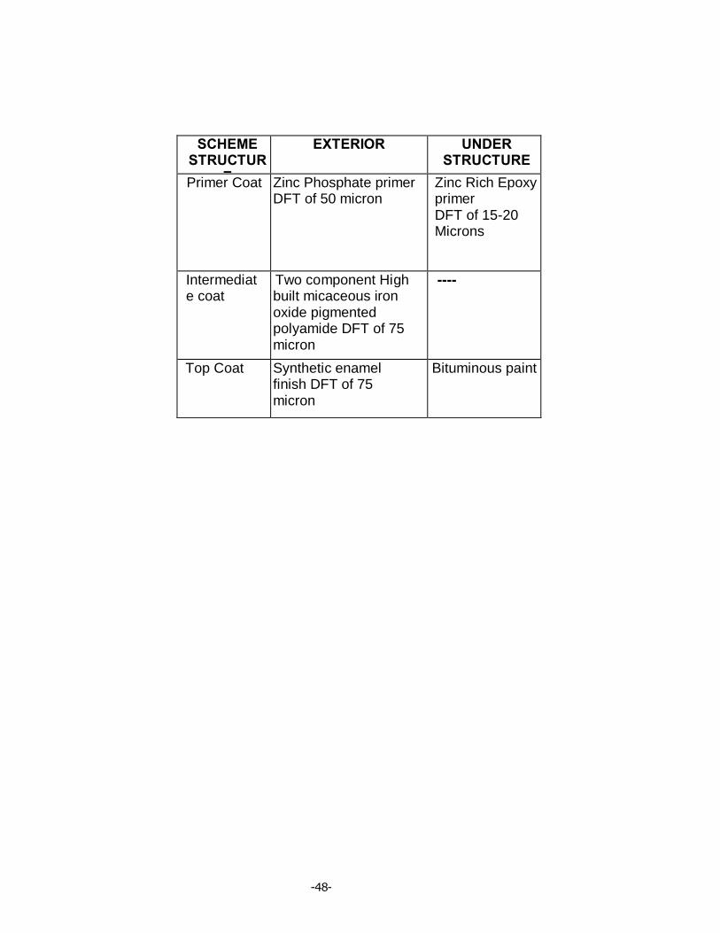
-48-
SCHEME STRUCTUR
E
EXTERIOR UNDER STRUCTURE
Primer Coat Zinc Phosphate primer DFT of 50 micron
Zinc Rich Epoxy primer DFT of 15-20 Microns
Intermediate coat
Two component High built micaceous iron oxide pigmented polyamide DFT of 75 micron
----
Top Coat Synthetic enamel finish DFT of 75 micron
Bituminous paint

[Type text] [Type text] [Type text]
5.0 Flooring System Thickness medium tensile steel sheet will be laid and stitch welded to the cross members and also to the peripheral structure to cater load as per load list chart of PDC.
6.0 Insulation E Houses will be insulated on sides, end walls and doors with 50mm thick Glass Wool. Roof with 80 mm. Densities should be 48 kg/m3
7.0 Inner Paneling Interiors of the E Houses will be aesthetically f i n ished so as to give a pleasing appearance with high quality workmanship. All joints will be neatly finished. For side, roof and end walls paneling will be done with 1.6mm thick Galvanised sheet. 8.0 Electrical The wiring circuit of the E House for lightings will include a suitable 1-phase power input socket, distribution board with MCB for the light connections and other additional points as required. Sufficient quantity 240
V, 1 Ph, 15A socket outlet shall be provided inside the E room Containers shall be provided with proper electrical wiring & sockets. Electrical wiring has to be done as per respective IS standard with proper earthing system. All wiring will be done in concealed type and superior quality PVC insulated copper cables will be used for the
purpose.
9.0 Lighting The lighting system shall maintain minimum levels as given below: Lux level shall be 300 inside the E-house and outside platforms/ stairs shall be 100. All luminaries shall be suitable for industrial duty and provided with IP65 housings for outdoor enclosures and IP54 for indoor enclosures. All fittings shall be weatherproof and able to withstand direct hosing.
[Type text] [Type text] [Type text]
10.0 CIVIL WORKS The scope of civil works for bidder covers design, engineering, supply of labor & materials, transportation, construction and commissioning of entire civil engineering works required for installation & erection of all the equipments, foundations, premises, etc as designed and / or supplied by him on Turnkey Basis. The major item of civil works under the scope of bidder covers the following:
1. RCC foundation, for installation of the containerized substation, which contains 33KV & 11KV Switchgear, LT AC & DC equipment etc.
2. RCC Foundation of the Transformers
Some Salient Feature of Civil foundation
Ø The tentative weight of the Container shall be 50 MT and hence foundation shall be designed accordingly based on SBC
Ø Foundation shall be of column type , the typical layout attached for reference.
Ø Foundation shall rest on Original Soil. Ø The concrete grade shall be M25 Ø Cement used shall be OPC 43 Ø Reinforcement shall be FE – 500
VOL-II(TS) E5-III- 33KV VCB (OUT DOOR) Page 1 of 10
36 KV VACCUM CIRCUIT BREAKERS (OUT DOOR TYPE)

VOL-II(TS) E5-III- 33KV VCB (OUT DOOR) Page 2 of 10
TABLE OF CONTENTS OF
36 KV VACCUM CIRCUIT BREAKERS (OUT DOOR TYPE)
NO DESCRIPTION PAGE NO
1.0. Scope 3
2.0 Standards 4
3.0 Climatic conditions 4
4.0 Technical Details 4
5.0 Constructional Features 4
6.0 Mountings 5
7.0 Temperature Rise 5
8.0 Insulation of the Circuit Breakers 5 9.0 Bushing and Insulations 6
10.0 Operation Mechanism 6 11.0 Terminal Connectors 7
12.0 Auxiliary Switches 7
13.0 Completeness of Equipment 7
14.0 Test 7
15.0 Inspection 8 16.0 Documentation 9
17.0 Packing and Forwarding 9

VOL-II(TS) E5-III- 33KV VCB (OUT DOOR) Page 3 of 10
TECHNICAL SPECIFICATION FOR 36 K.V. VACCUM CIRCUIT BREAKERS (OUTDOOR TYPE)
1.0. SCOPE:
36kV, 1430MVA Circuit Breakers are intended to be purchased for installation at different Sub-stations. Some of the Sub-stations for which equipment are tendered are situated in coastal areas where saline climate prevails. The base structure of the circuit breakers must be galvanized.
1.1. POWER SUPPLY TO AUXILIARIES : A.C. supply to auxiliaries will be 3 phase, 3 wire, 430 volt or single phase 250 volts at 50 C/s. The voltage variation will be within 10% and the frequency variation ± 5%.
1.2. 33 K.V. CIRCUIT BREAKERS TYPE AND RATING : The circuit breakers shall be vacuum type suitable for outdoor operation under
the climatic conditions specified without any protection from sum and rain. The circuit breaker shall have the following ratings :
Sl. No.
Description in details Required value
1. Number of poles : 3 (One unit with three phase making and breaking). 2. Frequency. : 50 C/s. 3. Nominal system voltage : 33 KV rms. 4. Highest system voltage : 36.0 KV rms. 5. Basic insulation level : 170 KVP 6. Power frequency test Voltage (wet). : 75 KV (rms.) 7. Nominal Current. : 1250 Amps rms. 7a. First pole to clear factor : 1.5 8. Breaking capacity. (a) Symmetrical : 25 KA/1430 MVA. (b)A symmetrical : 33 KA Peak 9. Making capacity : 62.5 KA Peak. 10. Continuous current rating : 1250 Amps (RMS) 11. Operating Duty : 0-0.3 Sec-CO-3 Min-CO. 12. (a) Break time : 3 Cycles (b)Make time : 5 Cycles (c )Minimum reclosing time : 15 Cycle. (d)Minimum dead time for reclosing : 15 Cycle 13. Dry one minute power frequency withstand test voltage a) Between line terminal : 75 KV rms. b) Between line and body : 75 KV rms. 14. Impulse withstand test voltage;
VOL-II(TS) E5-III- 33KV VCB (OUT DOOR) Page 4 of 10
a)Between terminal : 170 KV (Peak) with C.B. open. b)Between body & terminal : 170 KV (Peak) 15. Insulator or bushing a)Dry one minute power : 75 KV Frequency voltage, b)Wet one minute power : 75 KV Frequency withstand Voltage. c) Creepage distance : 580 mm (Minimum) 16. Short time current : Not less than 25 KA for rating for 3 seconds : 3 seconds. 17. Control circuit voltage : 48V D.C 2.0 STANDARDS :
The circuit breakers shall comply with the requirements of latest issue of IEC-62271-100, IEC-60694/IS12729:2004, IS-13118:1991.
3.0 CLIMATIC CONDITIONS : Please refer chapter E3 of Technical Specification on climatic conditions
For the purpose of the specification, the limit of ambient temperature shall be 50° C peak and 45° C average over a 24 hours period.
Some of the breakers to be purchased against this specification are intended to be installed on the sea coast having extremely saline climate. Necessary anti corrosive provisions need be incorporated.
4.0 TECHNICAL DETAILS 4.1 GENERAL :
a) The circuit breakers shall be of Vacuum type. The breakers shall be furnished as a complete unit with all accessories and equipment in place and all internal wiring installed and terminated in the mechanism.
b) The circuit breakers shall provide rapid and smooth interruption of current under all conditions, completely suppressing all undesirable phenomena even under the most severe and persistent short circuit conditions or when interrupting small currents of leading or lagging reactive current. The details of any device incorporated to limit or control the rate of rise of restricting voltages across the circuit breaker contacts shall be stated. The over voltages caused by the circuit breaker switching on inductive or capacitive load shall not exceed, 2.5 times the normal phase to neutral voltage. The total break time for the circuit breakers throughout the range of their operating duty shall be stated in the tender and guaranteed.
5.0 CONSTRUCTIONAL FEATURES : Each circuit breaker shall comprise 3 identical poles complete with a gang operated mechanism for specified duty. All these poles of the C.B. shall be linked together Electrically, Mechanically for specified duty.
VOL-II(TS) E5-III- 33KV VCB (OUT DOOR) Page 5 of 10
The breaker shall be capable of interruptions of low reactive current (lagging/leading) without undue over voltage and restrike.
a) CONTROL CUBICLE : A common control cubicle shall be furnished to house electrical controls, monitoring devices and all other accessories. The cubicle shall be of gasketed weather proof construction, fabricated from sheet Aluminum alloy sheet having minimum 3 mm thick. The operating mechanism shall be strong,rigid and not subject to rebound. The cubicle shall have front access door with lock and keys and removable gland plate at the bottom for owner’s cable entry. Thermostat controlled space heater, internal illumination lamp, 5A 3Pin socket with individual on off switches shall be provided in the cubicle.
6.0 MOUNTING : The circuit breakers shall be suitable for mounting on steel galvanized structures. The prices of necessary frames for mounting the circuit breaker shall be included with the offer. A ladder should be provided in the circuit breaker structure for easy access to the operating mechanism house. The ladder shall be of M.S with hot dip galvanised. The circuit breakers shall consist of three identical single phase units with a common operating mechanism. All joints shall be welded so as to have adequate mechanical strength. The breaker porcelain shall be capable of withstanding all pressure resulting from any specified performance of the breaker. The circuit breaker shall be supplied complete with the necessary lifting tools, foundation bolts and other accessories.
7.0 TEMPERATURE RISE : The maximum temperature attained by any part of the equipment when in-
service at site under continuous full load conditions and exposed to direct rays of sun shall not exceed the permissible limits fixed by approved specifications. When the standards specifies the limits of temperature rise these shall not exceed when corrected for the difference between ambient temperature at site and the ambient temperature specified in the specification.
8.0 INSULATION OF THE CIRCUIT BREAKERS : The insulation to ground, the insulation between open contacts, the insulation
between phases of the completely assembled circuit breakers, should be capable of withstanding satisfactorily die-electric test voltages corresponding to basic insulation level specified wheresoever in clause.
8.1 The clearance in open air shall be as follows, unless the apparatus is impulse tested after complete assembly.
i) Minimum clearance between phase : 505 mm ii) Phase to Earth : 305 mm
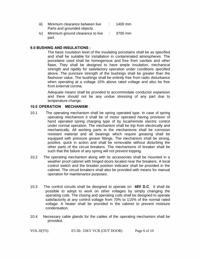
VOL-II(TS) E5-III- 33KV VCB (OUT DOOR) Page 6 of 10
iii) Minimum clearance between live : 1400 mm Parts and grounded objects.
iv) Minimum ground clearance to live : 3700 mm part. 9.0 BUSHING AND INSULATIONS :
The basic insulation level of the insulating porcelains shall be as specified and shall be suitable for installation in contaminated atmospheres. The porcelains used shall be homogenous and free from cavities and other flaws. They shall be designed to have ample insulation, mechanical strength and rigidity for satisfactory operation under conditions specified above. The puncture strength of the bushings shall be greater than the flashover value. The bushings shall be entirely free from radio disturbance when operating at a voltage 10% above rated voltage and also be free from external corona. Adequate means shall be provided to accommodate conductor expansion and there should not be any undue stressing of any part due to temperature change.
10.0 OPERATION MECHANISM :
10.1 The operating mechanism shall be spring operated type. In case of spring operating mechanism it shall be of motor operated having provision of hand operated spring charging type of by local/remote electric control under normal operation. The mechanism shall be trip from electrically and mechanically. All working parts in the mechanisms shall be corrosion resistant material and all bearings which require greasing shall be equipped with pressure grease fittings. The mechanism shall be strong, positive, quick in action and shall be removable without disturbing the other parts of the circuit breakers. The mechanisms of breaker shall be such that the failure of any spring will not prevent tripping.
10.2 The operating mechanism along with its accessories shall be mounted in a weather proof cabinet with hinged doors located near the breakers. A local control switch and the breaker position indicator shall be provided in the cabinet. The circuit breakers shall also be provided with means for manual operation for maintenance purposes.
10.3 The control circuits shall be designed to operate on 48V D.C. It shall be possible to adopt to work on other voltages by simply changing the operating coils. The closing and operating coils shall be designed to operate satisfactorily at any control voltage from 70% to 115% of the normal rated voltage. A heater shall be provided in the cabinet to prevent moisture condensation.
10.4 Necessary cable glands for the cables of the operating mechanism shall be
provided.
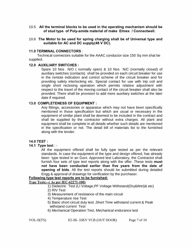
VOL-II(TS) E5-III- 33KV VCB (OUT DOOR) Page 7 of 10
10.5 All the terminal blocks to be used in the operating mechanism should be
of stud type of Poly-amide material of make Elmex / Connectwell. 10.6 The Motor to be used for spring charging shall be of Universal type and
suitable for AC and DC supply(48 V DC). 11.0 TERMINAL CONNECTORS : Technical connectors suitable for the AAAC conductor size 150 Sq mm shal be supplied. 12.0 AUXILIARY SWITCHES : Spare 10 Nos N/O ( normally open) & 10 Nos N/C (normally closed) of
auxiliary switches (contacts) shall be provided on each circuit breaker for use in the remote indication and control scheme of the circuit breaker and for providing safety interlocking etc. Special contact for use with trip coil and single short reclosing operation which permits relative adjustment with respect to the travel of the moving contact of the circuit breaker shall also be provided. There shall be provision to add more auxiliary switches at the later date if required.
13.0 COMPLETENESS OF EQUIPMENT : Any fittings, accessories or apparatus which may not have been specifically
mentioned in those specification but which are usual or necessary in the equipment of similar plant shall be deemed to be included in the contract and shall be supplied by the contractor without extra charges. All plant and equipment shall be complete in all details whether such details are mentioned in the specification or not. The detail bill of materials list to the furnished along with the tender.
14.0 TEST : 14.1 Type test : -
All the equipment offered shall be fully type tested as per the relevant standards. In case the equipment of the type and design offered, has already been type tested in an Govt. Approved test Laboratory, the Contractot shall furnish four sets of type test reports along with the offer. These tests must not have been conducted earlier than five years from the date of opening of bids. All the test reports should be submitted during detailed Engg & approval of drawings for verification by the purchaser.
Following type test reports are to be furnished: Type Tests:--( As per IEC-62271-100) 1) Dielectric Test (LI Voltage,PF Voltage Withstand(Dry&Wet)& etc) 2) RIV Test 3) Measurement of resistance of the main circuit 4) Temperature rise Test 5) Basic short circuit duty test ,Short Time withstand current & Peak
withstand current Test 6) Mechanical Operation Test, Mechanical endurance test

VOL-II(TS) E5-III- 33KV VCB (OUT DOOR) Page 8 of 10
7)Out of phase / Short Circuit making & Breaking Test 8) Capacitive Current, Switching Test , a) cable charging current Test b)Single capacitor Bank current switching test 9)Test to verify degree of protection 14.2 Routine Tests:- 1)Dielectric Tests on the main Circuit ,auxiliary & control circuits 2)Measurement of resistance of the main circuit. 3) Design & Visual Checks(Dimensions,clearances&etc) 4) Mechanical operation Test
5) Operating time of the device, motor Characteristics, measurement of coil current & resistance, SF6 gas pressure monitoring ,electrical scheme,control Circuit, antipumping, vaccum interrupter (type,make&etc), dimensions, name plate details, contact travel & timing checks .
14.3 Acceptance and Routine Tests.
All acceptance and routine tests as stipulated in the relevant standards & above shall be carried out by the supplier in presence of owner’s representative.
Immediately after finalization of the programme of acceptance /routine testing, the supplier shall give twenty days advance intimation to the purchaser, along with the shop routine test certificate and valid calibration certificates of the equipments/instruments calibrated in a govt. approved test house, to be used during testing for scrutiny,to enable him to depute his representative for witnessing the tests.
15.0 INSPECTION :
The inspection may be carried out by the purchaser at any stage of manufacture. The successful tendered shall grant free access to the purchaser’s representative at a reasonable time when the work is in progress. Inspection and acceptance of any equipments under this specification by the purchaser, shall not relieve the supplier in his obligation of furnishing equipment in accordance with the specification and shall not prevent subsequent rejection if the equipment is found to be defective.
The supplier shall keep the purchaser informed in advance, about the
manufacturing programme so that arrangement can be made for inspection. The purchaser reserves the right to insist for witnessing the acceptance/routine testing of the bought out items
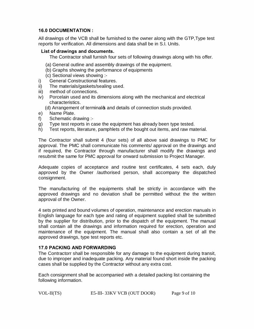
VOL-II(TS) E5-III- 33KV VCB (OUT DOOR) Page 9 of 10
16.0 DOCUMENTATION : All drawings of the VCB shall be furnished to the owner along with the GTP,Type test reports for verification. All dimensions and data shall be in S.I. Units. List of drawings and documents. The Contractor shall furnish four sets of following drawings along with his offer.
(a) General outline and assembly drawings of the equipment. (b) Graphs showing the performance of equipments (c) Sectional views showing :-
i) General Constructional features. ii) The materials/gaskets/sealing used. iii) method of connections. iv) Porcelain used and its dimensions along with the mechanical and electrical characteristics. (d) Arrangement of terminal’s and details of connection studs provided. e) Name Plate. f) Schematic drawing :- g) Type test reports in case the equipment has already been type tested. h) Test reports, literature, pamphlets of the bought out items, and raw material. The Contractor shall submit 4 (four sets) of all above said drawings to PMC for approval. The PMC shall communicate his comments/ approval on the drawings and if required, the Contractor through manufacturer shall modify the drawings and resubmit the same for PMC approval for onward submission to Project Manager. Adequate copies of acceptance and routine test certificates, 4 sets each, duly approved by the Owner /authorised person, shall accompany the dispatched consignment. The manufacturing of the equipments shall be strictly in accordance with the approved drawings and no deviation shall be permitted without the the written approval of the Owner. 4 sets printed and bound volumes of operation, maintenance and erection manuals in English language for each type and rating of equipment supplied shall be submitted by the supplier for distribution, prior to the dispatch of the equipment. The manual shall contain all the drawings and information required for erection, operation and maintenance of the equipment. The manual shall also contain a set of all the approved drawings, type test reports etc. 17.0 PACKING AND FORWARDING The Contractorr shall be responsible for any damage to the equipment during transit, due to improper and inadequate packing. Any material found short inside the packing cases shall be supplied by the Contractor without any extra cost. Each consignment shall be accompanied with a detailed packing list containing the following information.

VOL-II(TS) E5-III- 33KV VCB (OUT DOOR) Page 10 of 10
a)Name of the consignee. (i) Details of consignment. (ii) Destination (iii) Total weight of consignment. (iv) Sign showing upper/lower side of the crate. (v) Handling and unpacking instructions. (vi) Bill of material indicating contents of each package.
The supplier shall ensure that the packing list and bill of material are approved by the purchaser before dispatch.
TOPOGRAPHICAL AND METEOROLOGICAL SITE CONDITIONS Location of installations State of Orissa Altitude 1000 m Maximum Temperature 60°C Minimum Temperature 0°C Maximum daily average temperature 35°C Maximum humidity 100% Pollution level Heavy Airborne contamination, if any Highly Polluted Seismic withstand factor 0.3 g Maximum wind pressure 260 kg/m² Wind velocity 50m/sec Maximum rainfall per annum 2000 mm Average rainfall per annum 1500 mm Average no. of thunder-storm days/annum 70 Average no. of dust storm days per annum 20
VOL-II(TS) E5-II-STATION TRANSFORMER Page 1 of 31
TECHNICAL SPECIFICATION FOR
100KVA, 33/0.433kV STATION TRANSFORMER

VOL-II(TS) E5-II-STATION TRANSFORMER Page 2 of 31
TABLE OF CONTENTS OF
100KVA, 33/0.433kV STATION TRANSFORMER
NO DESCRIPTION PAGE NO 1.0 Scope 3 2.0 Standard ratings 3 3.0 Standards 3 4.0 Climatic conditions 4 5.0 Principal parameters 5 6.0 Technical requirements 5 7.0 Windings 6 8.0 Taps 7 9.0 Oil 7 10.0 Insulation levels 7 11.0 Losses 7 12.0 Tolerances 8 13.0 Percentage impedance 8 14.0 Temperature rise 8 15.0 Penalty for non performance 8 16.0 Insulation material 8 17.0 Tank 9 18.0 Conservator 10 19.0 Surface preparation and painting 11 20.0 Bushings 13 21.0 Terminal connectors 14 22.0 Terminal markings 15 23.0 Fittings 15 24.0 Fasteners 16 25.0 Overload capacity 16 26.0 Tests 17 27.0 Pressure relief device test 19 28.0 Short circuit test and impulse voltage withstand tests 19 29.0 Acceptance test 19 30.0 Inspection 20 31.0 Inspection and testing of transformer oil 20 32.0 Documentation 21 33.0 Packing and forwarding 22
VOL-II(TS) E5-II-STATION TRANSFORMER Page 3 of 31
34.0 Deviation 22
TECHNICAL SPECIFICATION FOR OUTDOOR TYPE 100 KVA,
33/.433KV STATION TRANSFORMER
1.0 SCOPE: 1.1 This specification covers design, engineering, manufacture, assembly, stage testing, inspection and testing before supply and delivery at site of oil immersed, naturally cooled 3 phase 100 KVA, 33kV/ 0.433KV station transformer for outdoor use. 1.2 It is not the intent to specify completely herein all the details of the design and construction of equipment. However, the equipment shall conform in all respects to high standards of engineering, design and workmanship and shall be capable of performing in continuous commercial operation, in a manner acceptable to the purchaser, who will interpret the meanings of drawings and specification and shall have the power to reject any work or material which, in his judgment is not in accordance therewith. The offered equipment shall be complete with all components necessary for their effective and trouble free operation. Such components shall be deemed to be within the scope of bidder’s supply irrespective of whether those are specifically brought out in this specification and / or the commercial order or not. 1.3 The transformer and accessories shall be designed to facilitate operation, inspection, maintenance and repairs. The design shall incorporate every precaution and provision for the safety of equipment as well as staff engaged in operation and maintenance of equipment. 1.4 All outdoor apparatus, including bushing insulators with their mountings, shall be designed so as to avoid any accumulation of water. 2.0 STANDARD RATINGS: 2.1 100 KVA,33/0.433 kV Station Transformers. 3.0 STANDARDS:
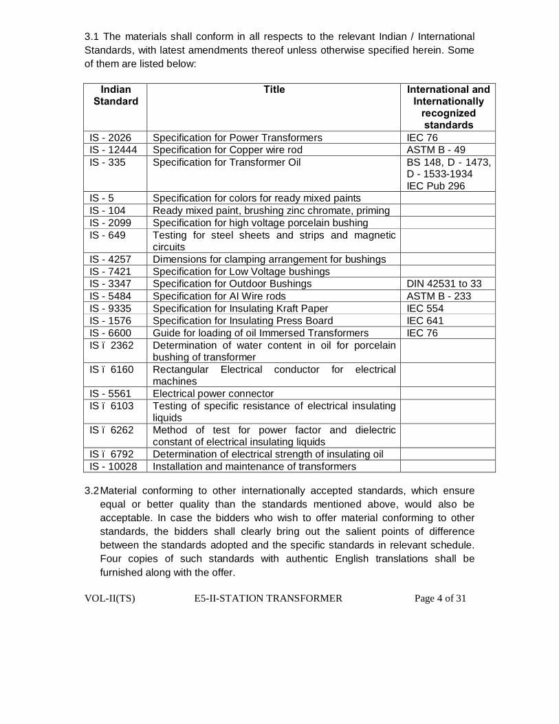
VOL-II(TS) E5-II-STATION TRANSFORMER Page 4 of 31
3.1 The materials shall conform in all respects to the relevant Indian / International Standards, with latest amendments thereof unless otherwise specified herein. Some of them are listed below:
Indian Standard
Title International and Internationally
recognized standards
IS - 2026 Specification for Power Transformers IEC 76 IS - 12444 Specification for Copper wire rod ASTM B - 49 IS - 335 Specification for Transformer Oil
BS 148, D - 1473, D - 1533-1934 IEC Pub 296
IS - 5 Specification for colors for ready mixed paints IS - 104 Ready mixed paint, brushing zinc chromate, priming IS - 2099 Specification for high voltage porcelain bushing IS - 649 Testing for steel sheets and strips and magnetic
circuits
IS - 4257 Dimensions for clamping arrangement for bushings IS - 7421 Specification for Low Voltage bushings IS - 3347 Specification for Outdoor Bushings DIN 42531 to 33 IS - 5484 Specification for AI Wire rods ASTM B - 233 IS - 9335 Specification for Insulating Kraft Paper IEC 554 IS - 1576 Specification for Insulating Press Board IEC 641 IS - 6600 Guide for loading of oil Immersed Transformers IEC 76 IS – 2362
Determination of water content in oil for porcelain bushing of transformer
IS – 6160
Rectangular Electrical conductor for electrical machines
IS - 5561 Electrical power connector IS – 6103
Testing of specific resistance of electrical insulating liquids
IS – 6262
Method of test for power factor and dielectric constant of electrical insulating liquids
IS – 6792 Determination of electrical strength of insulating oil IS - 10028 Installation and maintenance of transformers
3.2 Material conforming to other internationally accepted standards, which ensure
equal or better quality than the standards mentioned above, would also be acceptable. In case the bidders who wish to offer material conforming to other standards, the bidders shall clearly bring out the salient points of difference between the standards adopted and the specific standards in relevant schedule. Four copies of such standards with authentic English translations shall be furnished along with the offer.
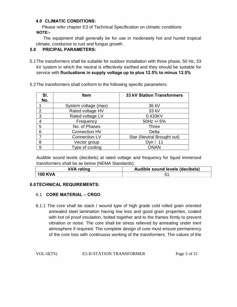
VOL-II(TS) E5-II-STATION TRANSFORMER Page 5 of 31
4.0 CLIMATIC CONDITIONS: Please refer chapter E3 of Technical Specification on climatic conditions NOTE:- The equipment shall generally be for use in moderately hot and humid tropical climate, conducive to rust and fungus growth .
5.0 PRICIPAL PARAMETERS:
5.1 The transformers shall be suitable for outdoor installation with three phase, 50 Hz, 33 kV system in which the neutral is effectively earthed and they should be suitable for service with fluctuations in supply voltage up to plus 12.5% to minus 12.5%
5.2 The transformers shall conform to the following specific parameters:
Sl. No.
Item 33 kV Station Transformers
1 System voltage (max) 36 kV 2 Rated voltage HV 33 kV 3 Rated voltage LV 0.433KV 4 Frequency 50Hz +/-5% 5 No. of Phases Three 6 Connection HV Delta 7 Connection LV Star (Neutral Brought out) 8 Vector group Dyn – 11 9 Type of cooling ONAN
Audible sound levels (decibels) at rated voltage and frequency for liquid immersed transformers shall be as below (NEMA Standards):
kVA rating Audible sound levels (decibels) 100 KVA 51
6.0 TECHNICAL REQUIREMENTS: 6.1 CORE MATERIAL – CRGO 6.1.1 The core shall be stack / wound type of high grade cold rolled grain oriented
annealed steel lamination having low loss and good grain properties, coated with hot oil proof insulation, bolted together and to the frames firmly to prevent vibration or noise. The core shall be stress relieved by annealing under inert atmosphere if required. The complete design of core must ensure permanency of the core loss with continuous working of the transformers. The values of the

VOL-II(TS) E5-II-STATION TRANSFORMER Page 6 of 31
maximum flux density allowed in the design and grade of lamination used shall be clearly stated in the offer
6.1.2 The bidder should offer the core for inspection and approval by the purchaser during manufacturing stage.
6.1.3 The transformers core shall be suitable for over fluxing (due to combined effect of voltage and frequency) up to 12.5% without injurious heating at full load conditions and shall not get saturated. The bidder shall furnish necessary design data in support of this situation.
6.1.4 No-load current shall not exceed 3% of full load current and will be measured by energizing the transformer at 433 volts, 50 Hz on the secondary. In crease of voltage of 433 volts by 12.5% shall not increase the no-load current by 6% (maximum) of full load current.
6.1.5 Flux density within the core should not exceed 1.6 web/sq meter at rated voltage & rated frequency.
7.0 WINDINGS:
7.1 Material:
7.1.1 HV and LV windings shall be wound from Supper Enamel covered / Double Paper covered copper conductor .
7.1.2 LV winding shall be such that neutral formation will be at top.
7.1.3 The winding construction of single HV coil wound over LV coil is preferable.
7.1.4 Inter layer insulation shall be Nomex / Epoxy dotted Kraft Paper.
7.1.5 Proper bounding of inter layer insulation with the conductor shall be ensured. Test for bounding strength shall be conducted.
7.1.6 Dimensions of winding coils are very critical. Dimensional tolerances for winding coils shall be within limits as specified in Guaranteed technical .
7.1.7 Current density for HV and LV winding should not be more that 2.8 Ampere per sq mm at rated current & normal tap.
7.1.8 The core / coil assembly shall be securely held in position to avoid any movement under short circuit conditions.
7.1.9 Joints in the winding shall be avoided. However, if jointing is necessary the joints shall be properly brazed and the resistance of the joints shall be less than that of
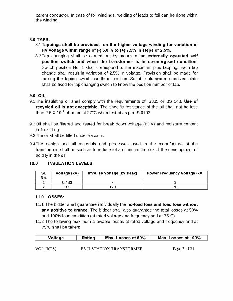
VOL-II(TS) E5-II-STATION TRANSFORMER Page 7 of 31
parent conductor. In case of foil windings, welding of leads to foil can be done within the winding.
8.0 TAPS: 8.1 Tappings shall be provided, on the higher voltage winding for variation of
HV voltage within range of (-) 5.0 % to (+) 7.5% in steps of 2.5%. 8.2 Tap changing shall be carried out by means of an externally operated self
position switch and when the transformer is in de-energised condition. Switch position No. 1 shall correspond to the maximum plus tapping. Each tap change shall result in variation of 2.5% in voltage. Provision shall be made for locking the taping switch handle in position. Suitable aluminium anodized plate shall be fixed for tap changing switch to know the position number of tap.
9.0 OIL: 9.1 The insulating oil shall comply with the requirements of IS335 or BS 148. Use of
recycled oil is not acceptable. The specific resistance of the oil shall not be less than 2.5 X 10¹² ohm-cm at 27oC when tested as per IS 6103.
9.2 Oil shall be filtered and tested for break down voltage (BDV) and moisture content before filling.
9.3 The oil shall be filled under vacuum.
9.4 The design and all materials and processes used in the manufacture of the transformer, shall be such as to reduce tot a minimum the risk of the development of acidity in the oil.
10.0 INSULATION LEVELS:
Sl. No.
Voltage (kV) Impulse Voltage (kV Peak) Power Frequency Voltage (kV)
1 0.433 - 3 2 33 170 70
11.0 LOSSES:
11.1 The bidder shall guarantee individually the no-load loss and load loss without any positive tolerance. The bidder shall also guarantee the total losses at 50% and 100% load condition (at rated voltage and frequency and at 75oC).
11.2 The following maximum allowable losses at rated voltage and frequency and at 75oC shall be taken:
Voltage Rating Max. Losses at 50% Max. Losses at 100%
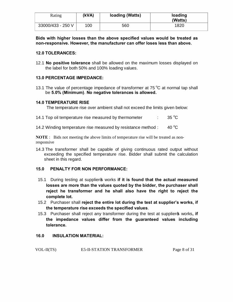
VOL-II(TS) E5-II-STATION TRANSFORMER Page 8 of 31
Rating
(kVA)
loading (Watts) loading (Watts)
33000/433 - 250 V 100 560 1820
Bids with higher losses than the above specified values would be treated as non-responsive. However, the manufacturer can offer loses less than above. 12.0 TOLERANCES: 12.1 No positive tolerance shall be allowed on the maximum losses displayed on
the label for both 50% and 100% loading values. 13.0 PERCENTAGE IMPEDANCE: 13.1 The value of percentage impedance of transformer at 75 oC at normal tap shall
be 5.0% (Minimum). No negative tolerances is allowed. 14.0 TEMPERATURE RISE The temperature rise over ambient shall not exceed the limits given below: 14.1 Top oil temperature rise measured by thermometer : 35 oC 14.2 Winding temperature rise measured by resistance method : 40 oC NOTE : Bids not meeting the above limits of temperature rise will be treated as non-responsive
14.3 The transformer shall be capable of giving continuous rated output without exceeding the specified temperature rise. Bidder shall submit the calculation sheet in this regard.
15.0 PENALTY FOR NON PERFORMANCE: 15.1 During testing at supplier’s works if it is found that the actual measured
losses are more than the values quoted by the bidder, the purchaser shall reject he transformer and he shall also have the right to reject the complete lot.
15.2 Purchaser shall reject the entire lot during the test at supplier’s works, if the temperature rise exceeds the specified values.
15.3 Purchaser shall reject any transformer during the test at supplier’s works, if the impedance values differ from the guaranteed values including tolerance.
16.0 INSULATION MATERIAL:
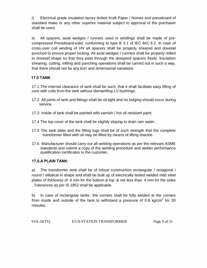
VOL-II(TS) E5-II-STATION TRANSFORMER Page 9 of 31
i) Electrical grade insulation epoxy dotted Kraft Paper / Nomex and pressboard of standard make or any other superior material subject to approval of the purchaser shall be used. ii) All spacers, axial wedges / runners used in windings shall be made of pre-compressed Pressboard-solid, conforming to type B 3.1 of IEC 641-3-2. In case of cross-over coil winding of HV all spacers shall be properly sheared and dovetail punched to ensure proper locking. All axial wedges / runners shall be properly milled to dovetail shape so that they pass through the designed spacers freely. Insulation shearing, cutting, milling and punching operations shall be carried out in such a way, that there should not be any burr and dimensional variations 17.0 TANK 17.1 The internal clearance of tank shall be such, that it shall facilitate easy lifting of core with coils from the tank without dismantling LV bushings. 17.2 All joints of tank and fittings shall be oil tight and no bulging should occur during
service. 17.3 Inside of tank shall be painted with varnish / hot oil resistant paint. 17.4 The top cover of the tank shall be slightly sloping to drain rain water. 17.5 The tank plate and the lifting lugs shall be of such strength that the complete
transformer filled with oil may be lifted by means of lifting shackle. 17.6 Manufacturer should carry out all welding operations as per the relevant ASME
standards and submit a copy of the welding procedure and welder performance qualification certificates to the customer.
17.0.A PLAIN TANK: a) The transformer tank shall be of robust construction rectangular / octagonal / round / elliptical in shape and shall be built up of electrically tested welded mild steel plates of thickness of 6 mm for the bottom & top ;& not less than 4 mm for the sides . Tolerances as per IS 1852 shall be applicable. b) In case of rectangular tanks the corners shall be fully welded at the corners from inside and outside of the tank to withstand a pressure of 0.8 kg/cm2 for 30 minutes.

VOL-II(TS) E5-II-STATION TRANSFORMER Page 10 of 31
c) Under operating conditions the pressure generated inside the tank should not exceed 0.4 kg/sq.cm positive or negative. d) The tank shall be reinforced by welded flats on all the outside walls on the edge of the tank. e) Permanent deflection: The permanent deflection, when the tank without oil is subjected to a vacuum of 525 mm of mercury for rectangular tank and 760 mm of mercury for round tank, shall not be more than the values as given below:
Horizontal length of flat plate in mm Permanent deflection in mm Upto and including 750 5.0
751 to 1250 6.5 1251 to 1750 8.0 1751 to 2000 9.5 2001 to 2250 11.0 2251 to 2500 12.0 2501 to 3000 16.0 Above 3000 19.0
f) The tank shall further be capable of withstanding a pressure of 0.8 kg/sq.cm (g) and a vacuum of 0.7 kg/sq.cm (g) without any deformation. g) The radiators can be tube or fin type or pressed steel type to achieve the desired cooling to limit specified temperature rise. 18.0 CONSERVATOR: 18.1 The conservator shall be provided on transformers for plain tank .
18.2 When a conservator is provided, oil gauge and the plain or dehydrating breathing device shall be fitted to the conservator which shall also be provided with a drain plug and a filling hole [32 mm (1¼”)] normal size thread with cover.
18.3 The dehydrating agent shall be silica gel. The moisture absorption shall be indicated by a change in the colour of the silica gel crystals which should be easily visible from a distance. Volume of breather shall be suitable for 1Kg of silica gel conforming to IS 3410 .
18.4 The capacity of a conservator tank shall be designed keeping in view the total quantity of oil and its contraction and expansion due to temperature variation.

VOL-II(TS) E5-II-STATION TRANSFORMER Page 11 of 31
The total volume of conservator shall be such as to contain 10% quantity of the oil. Normally 3% quantity the oil shall be contained in the conservator.
18.5 The cover of main tank shall be provided with an air release plug to enable air trapped within to be released, unless the conservator is so located as to eliminate the possibility of air being trapped within the main tank.
18.6 The inside diameter of the pipe connecting the conservator to the main tank should be within 20 to 50 mm and it should be projected into the conservator so that its end is approximately 20 mm above the bottom of the conservator so as to create a sump for collection of impurities. The minimum oil level (corresponding to 0oC) should be above the sump level.
19.0 SURFACE PREPARATION AND PAINTING: 19.1 GENERAL 19.1.1 All paints, when applied in a normal full coat, shall be free from runs, sags,
wrinkles, patchiness, brush marks or other defects.
19.1.2 All primers shall be well marked into the surface, particularly in areas where painting is evident and the first priming coat shall be applied as soon as possible after cleaning. The paint shall be applied by airless spray according to manufacturer’s recommendations. However, where ever airless spray is no possible, conventional spray be used with prior approval of purchaser.
19.2 CLEANING AND SURFACE PREPARATION: 19.2.1 After all machining, forming and welding has been completed, all steel
work surfaces shall be thoroughly cleaned of rust, scale, welding slag or spatter and other contamination prior to any painting.
19.2.2 Steel surfaces shall be prepared by shot blast cleaning (IS9954) to grade
Sq. 2.5 of ISO 8501-1 or chemical cleaning including phosphating of the appropriate quality (IS 3618).
19.2.3 Chipping scraping and steel wire brushing using manual or power driven
tools cannot remove firmly adherent mill-scale. These methods shall only be used where blast cleaning is impractical. Manufacturer to clearly explain such areas in his technical offer.
19.3 PROTECTIVE COATING:
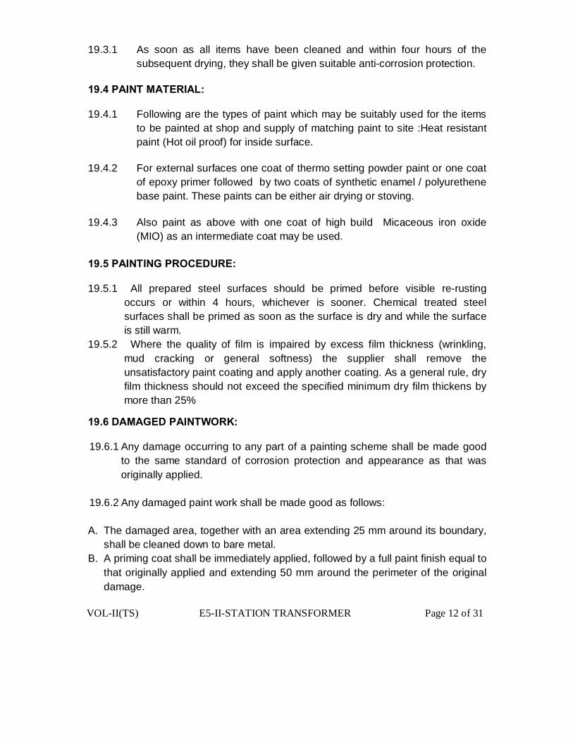
VOL-II(TS) E5-II-STATION TRANSFORMER Page 12 of 31
19.3.1 As soon as all items have been cleaned and within four hours of the
subsequent drying, they shall be given suitable anti-corrosion protection. 19.4 PAINT MATERIAL: 19.4.1 Following are the types of paint which may be suitably used for the items
to be painted at shop and supply of matching paint to site :Heat resistant paint (Hot oil proof) for inside surface.
19.4.2 For external surfaces one coat of thermo setting powder paint or one coat
of epoxy primer followed by two coats of synthetic enamel / polyurethene base paint. These paints can be either air drying or stoving.
19.4.3 Also paint as above with one coat of high build Micaceous iron oxide
(MIO) as an intermediate coat may be used. 19.5 PAINTING PROCEDURE: 19.5.1 All prepared steel surfaces should be primed before visible re-rusting
occurs or within 4 hours, whichever is sooner. Chemical treated steel surfaces shall be primed as soon as the surface is dry and while the surface is still warm.
19.5.2 Where the quality of film is impaired by excess film thickness (wrinkling, mud cracking or general softness) the supplier shall remove the unsatisfactory paint coating and apply another coating. As a general rule, dry film thickness should not exceed the specified minimum dry film thickens by more than 25%
19.6 DAMAGED PAINTWORK: 19.6.1 Any damage occurring to any part of a painting scheme shall be made good
to the same standard of corrosion protection and appearance as that was originally applied.
19.6.2 Any damaged paint work shall be made good as follows: A. The damaged area, together with an area extending 25 mm around its boundary,
shall be cleaned down to bare metal. B. A priming coat shall be immediately applied, followed by a full paint finish equal to
that originally applied and extending 50 mm around the perimeter of the original damage.
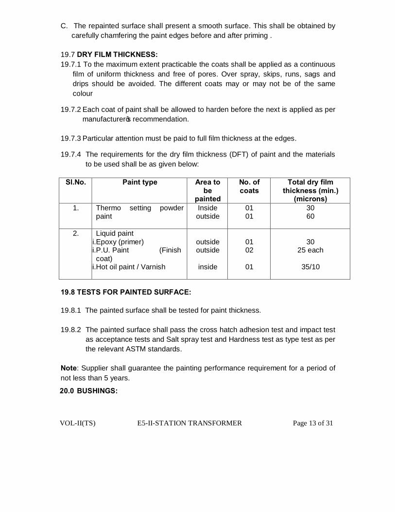
VOL-II(TS) E5-II-STATION TRANSFORMER Page 13 of 31
C. The repainted surface shall present a smooth surface. This shall be obtained by carefully chamfering the paint edges before and after priming .
19.7 DRY FILM THICKNESS: 19.7.1 To the maximum extent practicable the coats shall be applied as a continuous
film of uniform thickness and free of pores. Over spray, skips, runs, sags and drips should be avoided. The different coats may or may not be of the same colour
19.7.2 Each coat of paint shall be allowed to harden before the next is applied as per manufacturer’s recommendation.
19.7.3 Particular attention must be paid to full film thickness at the edges.
19.7.4 The requirements for the dry film thickness (DFT) of paint and the materials to be used shall be as given below:
Sl.No.
Paint type
Area to
be painted
No. of coats
Total dry film thickness (min.)
(microns) 1.
Thermo setting powder paint
Inside outside
01 01
30 60
2. Liquid paint i.Epoxy (primer) ii.P.U. Paint (Finish
coat) iii.Hot oil paint / Varnish
outside outside
inside
01 02
01
30
25 each
35/10
19.8 TESTS FOR PAINTED SURFACE: 19.8.1 The painted surface shall be tested for paint thickness. 19.8.2 The painted surface shall pass the cross hatch adhesion test and impact test
as acceptance tests and Salt spray test and Hardness test as type test as per the relevant ASTM standards.
Note: Supplier shall guarantee the painting performance requirement for a period of not less than 5 years.
20.0 BUSHINGS:
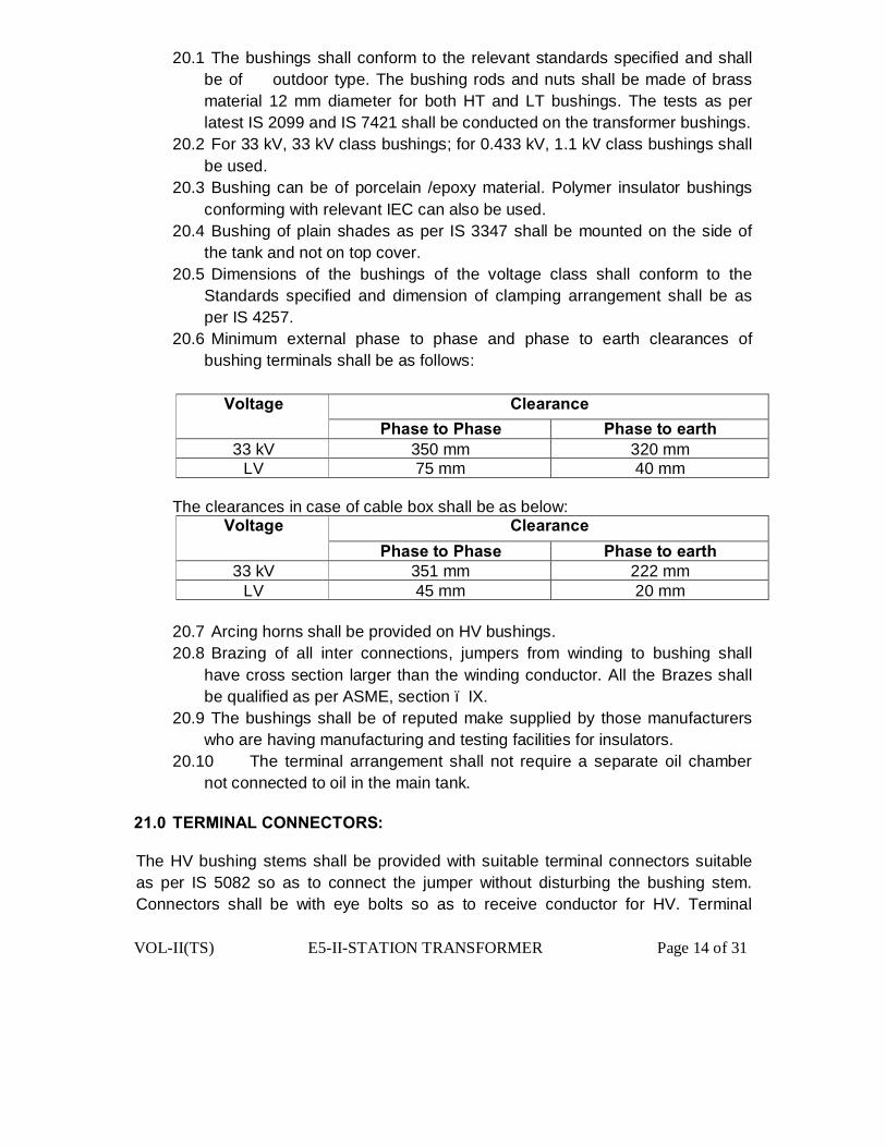
VOL-II(TS) E5-II-STATION TRANSFORMER Page 14 of 31
20.1 The bushings shall conform to the relevant standards specified and shall be of outdoor type. The bushing rods and nuts shall be made of brass material 12 mm diameter for both HT and LT bushings. The tests as per latest IS 2099 and IS 7421 shall be conducted on the transformer bushings.
20.2 For 33 kV, 33 kV class bushings; for 0.433 kV, 1.1 kV class bushings shall be used.
20.3 Bushing can be of porcelain /epoxy material. Polymer insulator bushings conforming with relevant IEC can also be used.
20.4 Bushing of plain shades as per IS 3347 shall be mounted on the side of the tank and not on top cover.
20.5 Dimensions of the bushings of the voltage class shall conform to the Standards specified and dimension of clamping arrangement shall be as per IS 4257.
20.6 Minimum external phase to phase and phase to earth clearances of bushing terminals shall be as follows:
Voltage Clearance Phase to Phase Phase to earth
33 kV 350 mm 320 mm LV 75 mm 40 mm
The clearances in case of cable box shall be as below:
Voltage Clearance Phase to Phase Phase to earth
33 kV 351 mm 222 mm LV 45 mm 20 mm
20.7 Arcing horns shall be provided on HV bushings. 20.8 Brazing of all inter connections, jumpers from winding to bushing shall
have cross section larger than the winding conductor. All the Brazes shall be qualified as per ASME, section – IX.
20.9 The bushings shall be of reputed make supplied by those manufacturers who are having manufacturing and testing facilities for insulators.
20.10 The terminal arrangement shall not require a separate oil chamber not connected to oil in the main tank.
21.0 TERMINAL CONNECTORS: The HV bushing stems shall be provided with suitable terminal connectors suitable as per IS 5082 so as to connect the jumper without disturbing the bushing stem. Connectors shall be with eye bolts so as to receive conductor for HV. Terminal

VOL-II(TS) E5-II-STATION TRANSFORMER Page 15 of 31
connectors shall be type tested as per IS 5561.The terminal arrangement for 433volts side shall be such as to suit 3 ½ X300 mm2 armoured PVC cable . 22.0 TERMINAL MARKINGS: High voltage phase windings shall be marked both in the terminal boards inside the tank and one the outside with capital letter 1U, 1V, 1W and low voltage winding for the same phase marked by corresponding small letter 2u, 2v, 2w. The neutral point terminal shall be indicated by the letter 2n. Neutral is to be brought out and connected to local grounding terminal by an earthing strip. 23.0 FITTINGS: The following standard fittings shall be provided:
i) Rating and terminal marking plates, non-detachable.
b. Earthing terminals with lugs – 2 Nos.
c. Lifting lugs for main tank and top cover.
d. Terminal connectors on the HV / LV bushings (For bare terminations only)
e. Thermometer pocket with cap – 1 No.
f. Air release device
g. HV bushings – 3 Nos.,
h. LV bushings – 4 Nos.
i. Pulling lugs.
j. Stiffener
k. Radiators – No. and length may be mentioned (as per heat dissipation calculations) / corrugations. l. Arcing horns on HT side 3 nos.
m. Prismatic oil level gauge.
n. Drain cum sampling valve.
o. Top filter valve.
p. Oil filling hole having p. 1- ¼” thread with plug and drain plug on the conservator. q. Silica gel breather.
VOL-II(TS) E5-II-STATION TRANSFORMER Page 16 of 31
r. Base channel 100 mm x 50 mm, 460 mm long with holes to make them suitable for fixing on a platform or plinth. s. 4 Nos. rollers
t. Pressure relief device or explosion vent.
24.0 FASTENERS: All bolts, studs screw threads, pipe threads, bolt heads and nuts shall comply with the appropriate Indian Standards for metric threads, or the technical equivalent. Bolts or studs shall not be less than 6 mm in diameter except when used for small wiring terminals. All nuts and pins shall be adequately locked. Wherever possible bolts shall be fitted in such a manner that in the event of failure of locking resulting in the nuts working loose and falling off, the bolt will remain in position. All ferrous bolts, nuts and washers placed in outdoor positions shall be treated to prevent corrosion, by hot dip galvanizing, except high tensile steel bolts and spring washers which shall be electro-galvanized / plated. Appropriate precautions shall be taken to prevent electrolytic action between dissimilar metals. Each bolt or stud shall project at least one thread but not more than three threads through the nut, except when otherwise approved for terminal board studs or relay stems. If bolts and nuts are placed so that they are in accessible by means of ordinary spanners, special spanners shall be provided. The length of the screwed portion of the bolts shall be such that no screw thread may form part of a shear plane between members. Taper washers shall b provided where necessary. Protective washers of suitable material shall be provided front and back of the securing screws. 25.0 OVERLOAD CAPACITY: a. The transformers shall be suitable for loading as per IS 6600.

VOL-II(TS) E5-II-STATION TRANSFORMER Page 17 of 31
26.0 TESTS:
26.1 The type tests as indicated at clause-28 below should have been conducted on
a transformer of same design during the last five years on the date of opening of techno-commercial bids. The bidder shall furnish type test reports during detailed Engineering & drawing approval.
26.2 The test certificates for all routine and type tests for the transformers and also for the bushings and transformer oil shall be submitted reports during detailed Engineering & drawing approval.
26.3 The procedure for testing shall be in accordance with IS 1180/2026 as the case may be except for temperature rise test.
26.4 Before dispatch each of the completely assembled transformers shall be subjected to the routine tests at the manufacturer’s works.
26.0A. ROUTINE TESTS: 26.1A Ratio, polarity, phase sequence , vector group & magnetic balance test. 26.2A No Load current and losses at service voltage and normal frequency. 26.3A Load losses at rated current and normal frequency. 26.4A Impedance voltage test. 26.4A Resistance of windings at each tap, cold (at or near the test bed temperature). 26.5A Insulation resistance at 60second,600 second & Polarisation Index (P.I i.e ratio of Insulation Resistance taken at 600seconds & at 60 seconds shall not be less than 1.5) 26.6A Induced over voltage withstand test. 26.7A Separate source voltage withstand test. 26.8A Neutral current measurement – The value of zero sequence current in the neutral of the star winding shall not be more than 2% of the full load current. 26.9A Oil samples (one sample per lot) to comply with IS 1866.
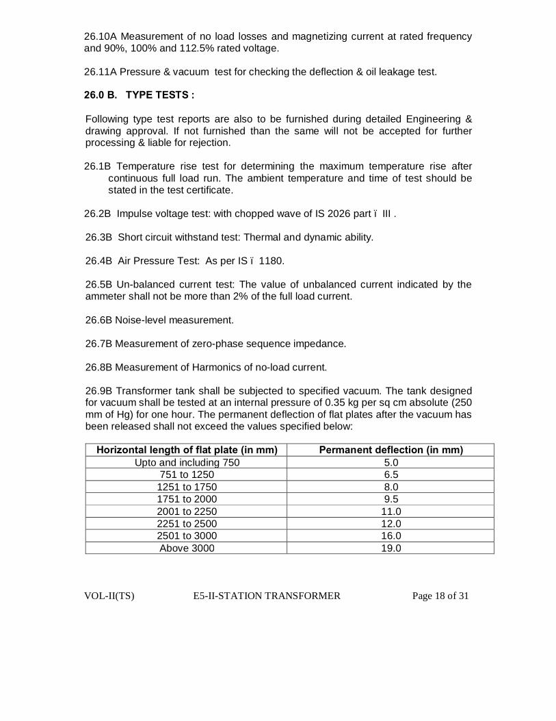
VOL-II(TS) E5-II-STATION TRANSFORMER Page 18 of 31
26.10A Measurement of no load losses and magnetizing current at rated frequency and 90%, 100% and 112.5% rated voltage. 26.11A Pressure & vacuum test for checking the deflection & oil leakage test. 26.0 B. TYPE TESTS : Following type test reports are also to be furnished during detailed Engineering & drawing approval. If not furnished than the same will not be accepted for further processing & liable for rejection. 26.1B Temperature rise test for determining the maximum temperature rise after
continuous full load run. The ambient temperature and time of test should be stated in the test certificate.
26.2B Impulse voltage test: with chopped wave of IS 2026 part – III . 26.3B Short circuit withstand test: Thermal and dynamic ability. 26.4B Air Pressure Test: As per IS – 1180. 26.5B Un-balanced current test: The value of unbalanced current indicated by the ammeter shall not be more than 2% of the full load current. 26.6B Noise-level measurement. 26.7B Measurement of zero-phase sequence impedance. 26.8B Measurement of Harmonics of no-load current. 26.9B Transformer tank shall be subjected to specified vacuum. The tank designed for vacuum shall be tested at an internal pressure of 0.35 kg per sq cm absolute (250 mm of Hg) for one hour. The permanent deflection of flat plates after the vacuum has been released shall not exceed the values specified below:
Horizontal length of flat plate (in mm) Permanent deflection (in mm) Upto and including 750 5.0
751 to 1250 6.5 1251 to 1750 8.0 1751 to 2000 9.5 2001 to 2250 11.0 2251 to 2500 12.0 2501 to 3000 16.0 Above 3000 19.0

VOL-II(TS) E5-II-STATION TRANSFORMER Page 19 of 31
26.10B Transformer tank together with its radiator and other fitting s shall be subjected to pressure corresponding to twice the normal pressure or 0.35 kg / sq.cm which ever is lower, measured at the base of the tank and maintained for an hour. The permanent deflection of the flat plates after the excess pressure has been released, shall not exceed the figures for vacuum test.
27.0 Pressure relief device test:
The pressure relief device shall be subject to increasing fluid pressure. It shall operate before reaching the test pressure as specified in the above class. The operating pressure shall be recorded. The device shall seal-off after the excess pressure has been released.
28.0 Short Circuit Test and Impulse Voltage Withstand Tests:
The purchaser intends to procure transformers designed and successfully tested for short circuit and impulse test. In case the transformers proposed for supply against the order are not exactly as per the tested design, the supplier shall be required to carry out the short circuit test and impulse voltage withstand test at their own cost in the presence of the representative of the purchaser.
28.1 The supply shall be accepted only after such test is done successfully, as it confirms on successful withstand of short circuit and healthiness of the active parts thereafter on un-tanking after a short circuit test.
28.2 Apart form dynamic ability test, the transformers shall also be required to withstand thermal ability test or thermal withstand ability will have to be established by way of calculations.
28.3 It may also be noted that the purchaser reserves the right to conduct short circuit test and impulse voltage withstand test in accordance with the IS, afresh on each ordered rating at purchaser cost, even if the transformers of the same rating and similar design are already tested. This test shall be carried out on a transformer to be selected by the purchaser either at the manufacturer’s works when they are offered in a lot for supply or randomly form the supplies already made to purchaser’s stores. The findings and conclusions of these tests shall be binding on the supplier.
28.4 Type test certificates for the tests carried out on prototype of same specifications shall be submitted along with the bid. The purchaser may select the transformer for type tests randomly.
29.0 ACCEPTANCE TEST:

VOL-II(TS) E5-II-STATION TRANSFORMER Page 20 of 31
29.1 All transformers shall be subjected to the stage inspection, routine & acceptance test as indicated above in presence of purchaser’s representative at the place of manufacture before dispatch without any extra charges. The testing shall be carried out in accordance with IS:1180 and IS:2026.
29.2 Checking of weights, dimensions, fitting and accessories, tank sheet thickness, oil quality, material, finish and workmanship as per GTP and contract drawings.
29.3 Physical verification of core coil assembly and measurement of flux density of
one unit of each rating, in every inspection with reference to short circuit test report.
29.4 Temperature rise test on one unit of the total ordered quantity.- This test
shall be carried out as per IS.
29.5 The pressure & vacuum test on the tank on one unit/lot randomly selected to be carried out as per Sl No. 28.8 & 28.9.
29.0A TESTS AT SITE: The purchaser reserves the right to conduct all tests on transformer after arrival at site and the manufacturer shall guarantee test certificate figures under actual service conditions. 30.0 INSPECTION: 30.1 In respect of raw material such as core stampings, winding conductors,
insulating paper and oil, supplier shall use materials manufactured / supplied by standard manufacturers and furnish the manufacturers’ test certificate as well as the proof of purchase from these manufacturers (excise gate pass) for information of the purchaser. The bidder shall furnish following documents along with their offer in respect of the raw materials:
(a) Invoice of supplier. (b) Mill’s certificate. (c) Packing list. (d) Bill of landing. (e) Bill of entry certificate by custom. 31.0 INSPECTION AND TESTING OF TRANSFORMER OIL: 31.1 To ascertain the quality of the transformer oil, the original manufacturer’s tests
report should be submitted at the time of inspection. Arrangements should also be made for testing of transformer oil, after taking out the sample from the
VOL-II(TS) E5-II-STATION TRANSFORMER Page 21 of 31
manufactured transformers and tested in the presence of purchaser’s representative.
31.2 To ensure about the quality of transformers, the inspection shall be carried out
by the purchaser’s representative at following two stages:- 31.2.1 On line anytime during receipt of raw material and manufacture / assembly
whenever the purchaser desires. 31.2.2 At finished stage i.e. transformers are fully assembled and are ready for dispatch. 31.2.3 All tests and inspection shall be carried out at the place of manufacture
unless otherwise specifically agreed upon by the manufacturer and purchaser at the time of purchase. The manufacturer shall offer the Inspector representing the Purchaser all reasonable facilities, without charges, to satisfy him that the material is being supplied in accordance with this specification. this will include Stage Inspection during manufacturing stage as well as Active Part Inspection during Acceptance Tests.
31.2.4 The manufacturer shall provide all services to establish and maintain quality of
workmanship in his works and that of his sub-contractors to ensure the mechanical / electrical performance of components, compliance with drawings, identification and acceptability of al materials, parts and equipment as per latest quality standards of ISO 9000.
31.2.5 Purchaser shall have every right to appoint a third party inspection to carryout
the inspection process. 31.2.6 The purchaser has the right to have the test carried out at his own cost by an
independent agency wherever there is a dispute regarding the quality supplied. Purchaser has right to test 1% of the supply selected either from the stores or field to check the quality of the product. In case of any deviation purchaser have every right to reject the entire lot or penalize the manufacturer, which may lead to blacklisting, among other things.
32.0 DOCUMENTATION: 33.1 The bidder shall furnish along with the bid the dimensional drawings of the
items offered indicating all the fittings. 33.2 Dimensional tolerances. 33.3 Weight of individual components and total weight.
VOL-II(TS) E5-II-STATION TRANSFORMER Page 22 of 31
33.4 An outline drawing front (both primary and secondary sides) and end-elevation and plan of the tank and terminal gear, wherein the principal dimensions shall be given.
33.5 Typical general arrangement drawings of the windings with the details of the
insulation at each point and core construction of transformer.
33.6 Typical general arrangement drawing showing both primary and secondary sides and end-elevation and plan of the transformer.
33.0 PACKING AND FORWARDING: 34.1 The packing shall be done as per the manufacturer’s standard practice.
However, it should be ensured that the packing is such that, the material would not get damaged during transit by Rail / Road / Sea.
34.2 The marking on each package shall be as per the relevant IS. 34.0 DEVIATION: 35.1 The bidders are not allowed to deviate from the principal requirements of the
Specifications. However, the bidder is required to submit with his bid in the relevant schedule a detailed list of all deviations without any ambiguity. In the absence of a deviation list in the deviation schedules, it is understood that such bid conforms to the bid specification and no post-bid negotiations shall take place in this regard.
35.2 The discrepancies, if any, between the specification and the catalogues and / or
literatures submitted as part of the offer by the bidders, shall not be considered and representations in this regard shall not be entertained.
35.3 If it is observed that there are deviations in the offer in guaranteed technical particulars other than those specified in the deviation schedules then such deviations shall be treated as deviations.
35.4 All the tables shall be prepared by vendor and are to be enclosed with the bid.

VOL-II(TS) E5-II-STATION TRANSFORMER Page 23 of 31
ANNEXURE-I
PROFOREMA FOR PRE-DELIVERY INSPECTION OF STATION TRANSFORMERS
1. Name of the firm. 2. Details of offer made (i) Order No. and Date. (ii) Rating. (iii) Quantity. (iv) Sl. No. of transformer. 3. Date of stage inspection clearance. 4. Reference of stage inspection clearance. 5. Quantity offered and inspected against the order
prior to this lot.
ANNEXURE-II ROUTINE/ ACCEPTANCE TESTS TO BE CARRIED OUT(Clause-27,29 above & ISS) Sl. PARTICULARS OBSERVATIONS.
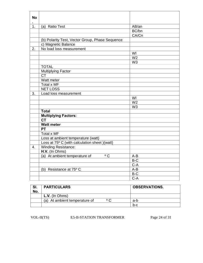
VOL-II(TS) E5-II-STATION TRANSFORMER Page 24 of 31
No. 1. (a) Ratio Test AB/an BC/bn CA/Cn (b) Polarity Test, Vector Group, Phase Sequence c) Magnetic Balance 2. No load loss measurement Wl W2 W3 TOTAL Multiplying Factor CT Watt meter Total x MF NET LOSS 3. Load loss measurement Wl W2 W3 Total Multiplying Factors: CT Watt meter PT Total x MF Loss at ambient temperature (watt) Loss at 75º C (with calculation sheet )(watt) 4. Winding Resistance: H.V. (In Ohms) (a) At ambient temperature of º C A-B B-C C-A (b) Resistance at 75º C A-B B-C C-A Sl. No.
PARTICULARS OBSERVATIONS.
L.V. (In Ohms) (a) At ambient temperature of º C a-b b-c
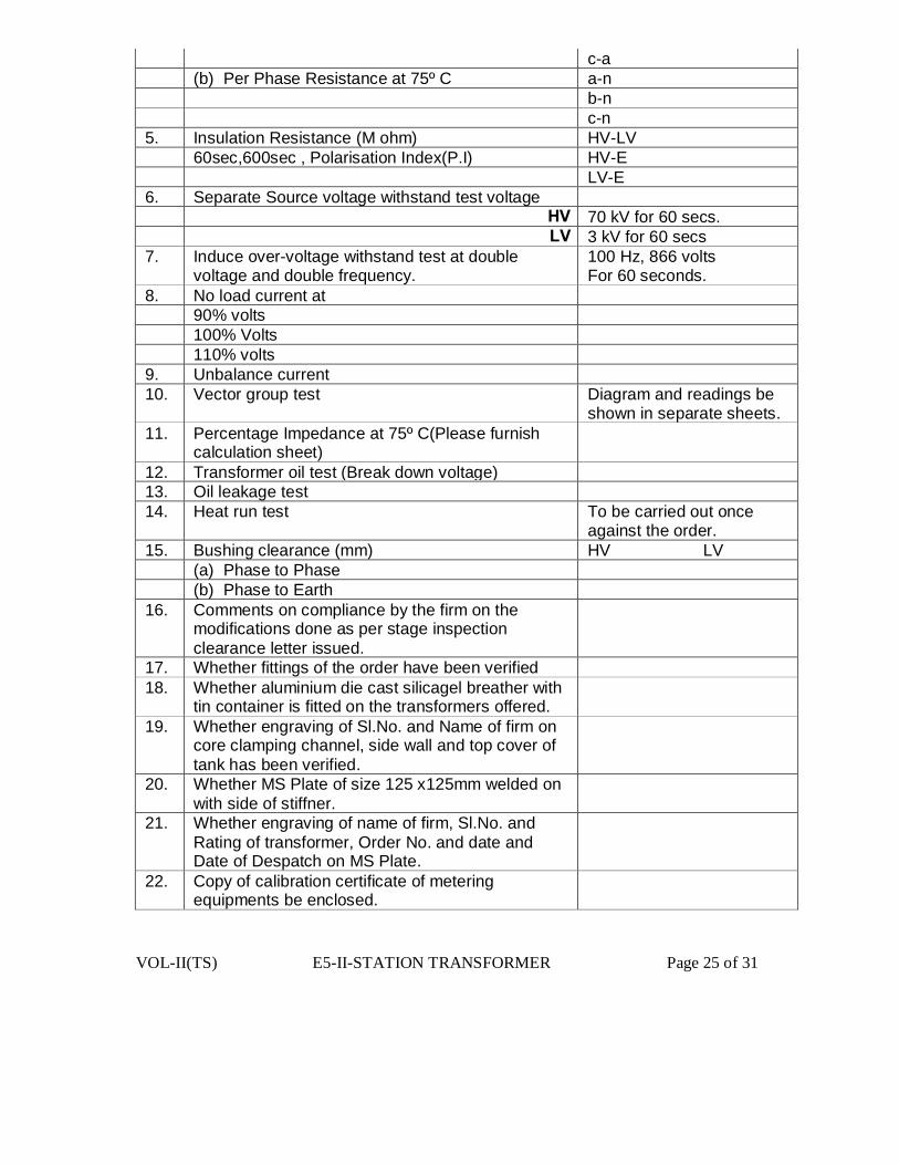
VOL-II(TS) E5-II-STATION TRANSFORMER Page 25 of 31
c-a (b) Per Phase Resistance at 75º C a-n b-n c-n 5. Insulation Resistance (M ohm) HV-LV 60sec,600sec , Polarisation Index(P.I) HV-E LV-E 6. Separate Source voltage withstand test voltage HV 70 kV for 60 secs. LV 3 kV for 60 secs 7. Induce over-voltage withstand test at double
voltage and double frequency. 100 Hz, 866 volts For 60 seconds.
8. No load current at 90% volts 100% Volts 110% volts 9. Unbalance current 10. Vector group test Diagram and readings be
shown in separate sheets. 11. Percentage Impedance at 75º C(Please furnish
calculation sheet)
12. Transformer oil test (Break down voltage) 13. Oil leakage test 14.
Heat run test To be carried out once against the order.
15. Bushing clearance (mm) HV LV (a) Phase to Phase (b) Phase to Earth 16. Comments on compliance by the firm on the
modifications done as per stage inspection clearance letter issued.
17. Whether fittings of the order have been verified 18. Whether aluminium die cast silicagel breather with
tin container is fitted on the transformers offered.
19. Whether engraving of Sl.No. and Name of firm on core clamping channel, side wall and top cover of tank has been verified.
20. Whether MS Plate of size 125 x125mm welded on with side of stiffner.
21. Whether engraving of name of firm, Sl.No. and Rating of transformer, Order No. and date and Date of Despatch on MS Plate.
22.
Copy of calibration certificate of metering equipments be enclosed.

VOL-II(TS) E5-II-STATION TRANSFORMER Page 26 of 31
Note:- If the Purchaser’s Inspecting officer wants to note & incorporate any other readings pertaining to the above tests then the same shall have to be incorporated in the test report by the supplier. Also if the inspecting officer decides to carry out any other low voltage tests to know the soundness of the transformer then the same shall have to be carried out by the supplier. Note : Please ensure that complete details have been filled in the proforma and no column has been left blank.
GUARANTEED AND OTHER PARTICULARS FOR STATION (GTP to be in Another
Annexure) TRANSFORMERS
(To be furnished by the Manufacturer) Sl. No. Description.
1. Make
2. name of Manufacturer
3. Place of Manufacture
4. Voltage Ratio
5. Rating in kVA
6. Core Material used and Grade:
a) Flux density
b) Over fluxing without saturation
(Curve to be furnished by the
Manufacturer in support of his claim)
7. Maximum temperature rise of:
a) windings by resistance method
b) Oil by thermometer
8. Magnetizing (no-load) current at:
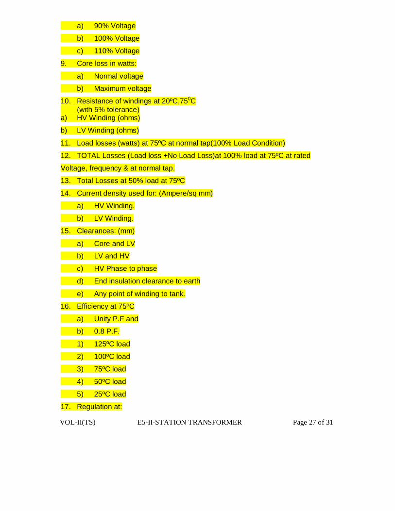
VOL-II(TS) E5-II-STATION TRANSFORMER Page 27 of 31
a) 90% Voltage
b) 100% Voltage
c) 110% Voltage
9. Core loss in watts:
a) Normal voltage
b) Maximum voltage
10. Resistance of windings at 20ºC,750C (with 5% tolerance) a) HV Winding (ohms)
b) LV Winding (ohms)
11. Load losses (watts) at 75ºC at normal tap(100% Load Condition)
12. TOTAL Losses (Load loss +No Load Loss)at 100% load at 75ºC at rated
Voltage, frequency & at normal tap.
13. Total Losses at 50% load at 75ºC
14. Current density used for: (Ampere/sq mm)
a) HV Winding.
b) LV Winding.
15. Clearances: (mm)
a) Core and LV
b) LV and HV
c) HV Phase to phase
d) End insulation clearance to earth
e) Any point of winding to tank.
16. Efficiency at 75ºC
a) Unity P.F and
b) 0.8 P.F.
1) 125ºC load
2) 100ºC load
3) 75ºC load
4) 50ºC load
5) 25ºC load
17. Regulation at:
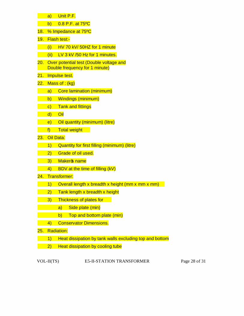
VOL-II(TS) E5-II-STATION TRANSFORMER Page 28 of 31
a) Unit P.F.
b) 0.8 P.F. at 75ºC
18. % Impedance at 75ºC
19. Flash test:-
(i) HV 70 kV/ 50HZ for 1 minute
(ii) LV 3 kV /50 Hz for 1 minutes.
20. Over potential test (Double voltage and Double frequency for 1 minute)
21. Impulse test.
22. Mass of : (kg)
a) Core lamination (minimum)
b) Windings (minimum)
c) Tank and fittings
d) Oil
e) Oil quantity (minimum) (litre)
f) Total weight
23. Oil Data:
1) Quantity for first filling (minimum) (litre)
2) Grade of oil used.
3) Maker’s name
4) BDV at the time of filling (kV)
24. Transformer:
1) Overall length x breadth x height (mm x mm x mm)
2) Tank length x breadth x height
3) Thickness of plates for
a) Side plate (min)
b) Top and bottom plate (min)
4) Conservator Dimensions.
25. Radiation:
1) Heat dissipation by tank walls excluding top and bottom
2) Heat dissipation by cooling tube
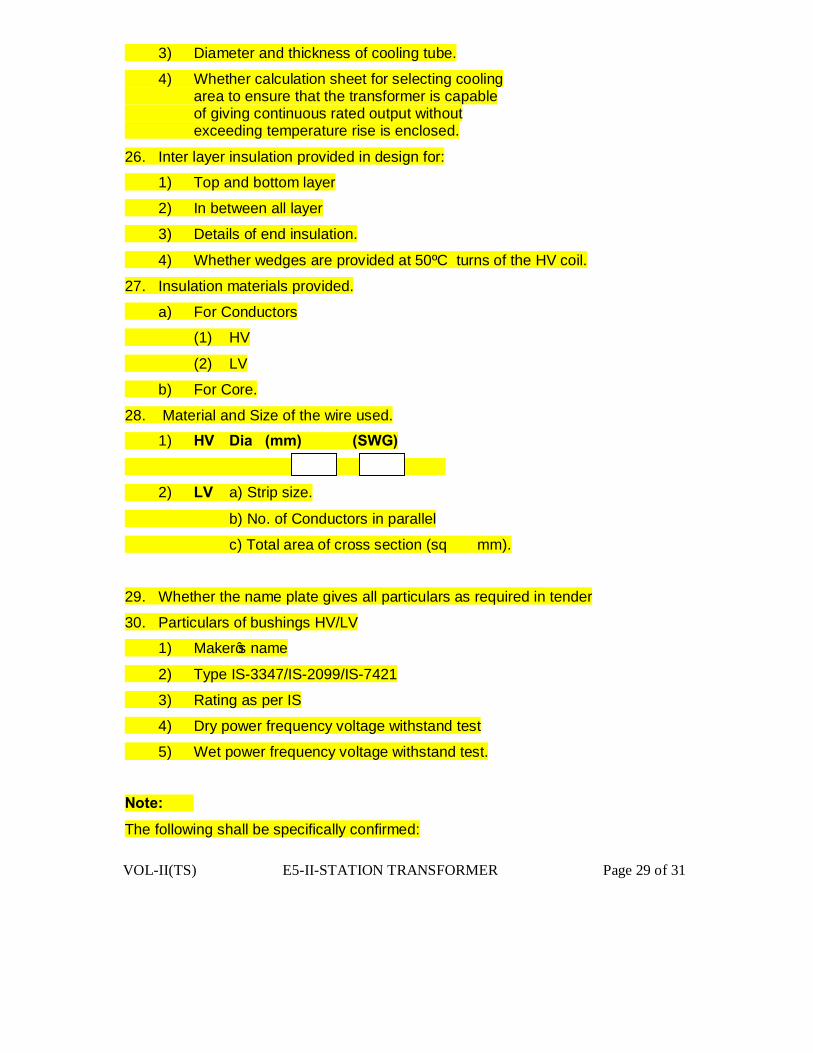
VOL-II(TS) E5-II-STATION TRANSFORMER Page 29 of 31
3) Diameter and thickness of cooling tube.
4) Whether calculation sheet for selecting cooling area to ensure that the transformer is capable of giving continuous rated output without exceeding temperature rise is enclosed.
26. Inter layer insulation provided in design for:
1) Top and bottom layer
2) In between all layer
3) Details of end insulation.
4) Whether wedges are provided at 50ºC turns of the HV coil.
27. Insulation materials provided.
a) For Conductors
(1) HV
(2) LV
b) For Core.
28. Material and Size of the wire used.
1) HV Dia (mm) (SWG)
2) LV a) Strip size.
b) No. of Conductors in parallel
c) Total area of cross section (sq mm).
29. Whether the name plate gives all particulars as required in tender
30. Particulars of bushings HV/LV
1) Maker’s name
2) Type IS-3347/IS-2099/IS-7421
3) Rating as per IS
4) Dry power frequency voltage withstand test
5) Wet power frequency voltage withstand test.
Note:
The following shall be specifically confirmed:

VOL-II(TS) E5-II-STATION TRANSFORMER Page 30 of 31
1) Whether the offer conforms to the limits of impedance mentioned in the specification. 2) Whether the offer conforms to the limits of temperature rise mentioned in the specification. 3) Whether the losses of the transformers offered are within the limits specified. 4) Whether the transformer offered is already type tested for the design and test reports enclosed. Sl. No.
Description
1. Core Grade 2. Core diameter mm 3. Gross core area Sq cm 4. Net core area Sq cm 5. Flux density Tesla 6. Mass of core Kg 7. Loss per kg of core at the specified flux density watt 8. Core window height mm 9. Center to enter distance of the core mm 10. No.of LV Turns 11. No.of HV turns 12. Size of LV conductor bare/covered mm 13. Size o HV conductor bare/covered mm 14. No. of parallels 15. Current density of LV winding. A/sq mm 16. Current density of HV winding. A/sq mm 17. Wt. of the LV winding for Transformer kg 18. Wt. of the HV winding for Transformer Kg 19. No. of LV Coils/phase 20. No. of HV Coils/phase 21. Height of LV Winding. mm 22. Height of HV Winding. mm 23. ID/OD of HV winding mm 24. ID/OD of LV winding mm 25. Size of the duct in LV winding mm 26. Size of the duct in HV winding mm 27. Size of the duct between HV and LV mm 28. HV winding to LV winding clearance mm 29. HV winding to tank clearance mm 30. Calculated impedance % 31. HV to earth creepage distance mm 32. LV to earth creepage distance mm

VOL-II(TS) E5-II-STATION TRANSFORMER Page 31 of 31
VOL-II (TS) E5-I-POWER TRANSFORMER Page-1 of 61
TECHINICAL SPECIFICATIONS FOR 3.15 / 5.00 / 8.00 MVA,
33/11KV ONAN POWER TRANSFORMERS
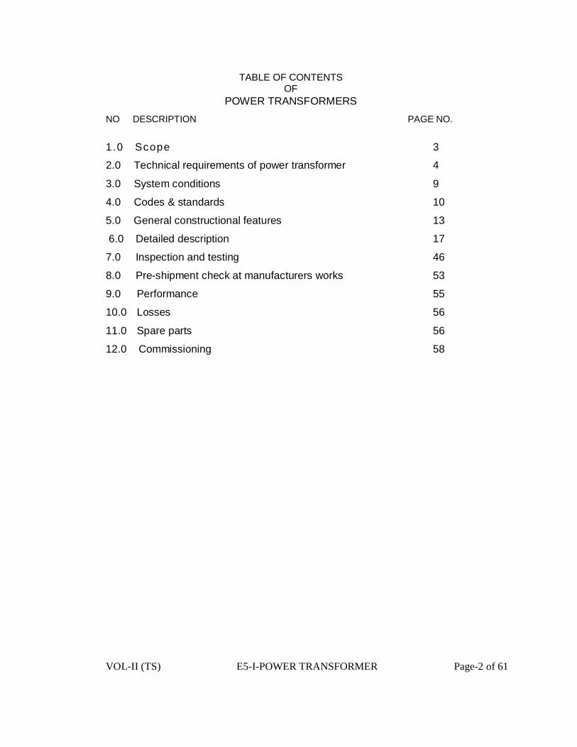
VOL-II (TS) E5-I-POWER TRANSFORMER Page-2 of 61
TABLE OF CONTENTS OF
POWER TRANSFORMERS
NO DESCRIPTION PAGE NO.
1.0 Scope 3
2.0 Technical requirements of power transformer 4
3.0 System conditions 9
4.0 Codes & standards 10
5.0 General constructional features 13
6.0 Detailed description 17
7.0 Inspection and testing 46
8.0 Pre-shipment check at manufacturers works 53
9.0 Performance 55
10.0 Losses 56
11.0 Spare parts 56
12.0 Commissioning 58
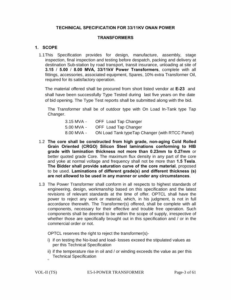
VOL-II (TS) E5-I-POWER TRANSFORMER Page-3 of 61
TECHINICAL SPECIFICATION FOR 33/11KV ONAN POWER
TRANSFORMERS
1. SCOPE
1.1 This Specification provides for design, manufacture, assembly, stage inspection, final inspection and testing before despatch, packing and delivery at destination Sub-station by road transport, transit insurance, unloading at site of 3.15 / 5.00 / 8.00 MVA, 33/11kV Power Transformers, complete with all fittings, accessories, associated equipment, Spares, 10% extra Transformer Oil, required for its satisfactory operation.
The material offered shall be procured from short listed vendor at E-23 and shall have been successfully Type Tested during last five years on the date of bid opening. The Type Test reports shall be submitted along with the bid.
The Transformer shall be of outdoor type with On Load In-Tank type Tap
Changer.
3.15 MVA - OFF Load Tap Changer 5.00 MVA - OFF Load Tap Changer 8.00 MVA - ON Load Tank typeTap Changer (with RTCC Panel) 1.2 The core shall be constructed from high grade, non-aging Cold Rolled
Grain Oriented (CRGO) Silicon Steel laminations conforming to HIB grade with lamination thickness not more than 0.23mm to 0.27mm or better quoted grade Core. The maximum flux density in any part of the core and yoke at normal voltage and frequency shall not be more than 1.5 Tesla. The Bidder shall provide saturation curve of the core material, proposed to be used. Laminations of different grade(s) and different thickness (s) are not allowed to be used in any manner or under any circumstances.
1.3 The Power Transformer shall conform in all respects to highest standards of engineering, design, workmanship based on this specification and the latest revisions of relevant standards at the time of offer. OPTCL shall have the power to reject any work or material, which, in his judgment, is not in full accordance therewith. The Transformer(s) offered, shall be complete with all components, necessary for their effective and trouble free operation. Such components shall be deemed to be within the scope of supply, irrespective of whether those are specifically brought out in this specification and / or in the commercial order or not.
OPTCL reserves the right to reject the transformer(s)-
i) if on testing the No-load and load- losses exceed the stipulated values as per this Technical Specification
ii) if the temperature rise in oil and / or winding exceeds the value as per this Technical Specification
iii)
VOL-II (TS) E5-I-POWER TRANSFORMER Page-4 of 61
iii)if impedance value differs from the guaranteed value including tolerance as per this specification iv) On Inspection and testing, if any of the technical data does not comply to
this specification, bid offer and approved drawings etc.
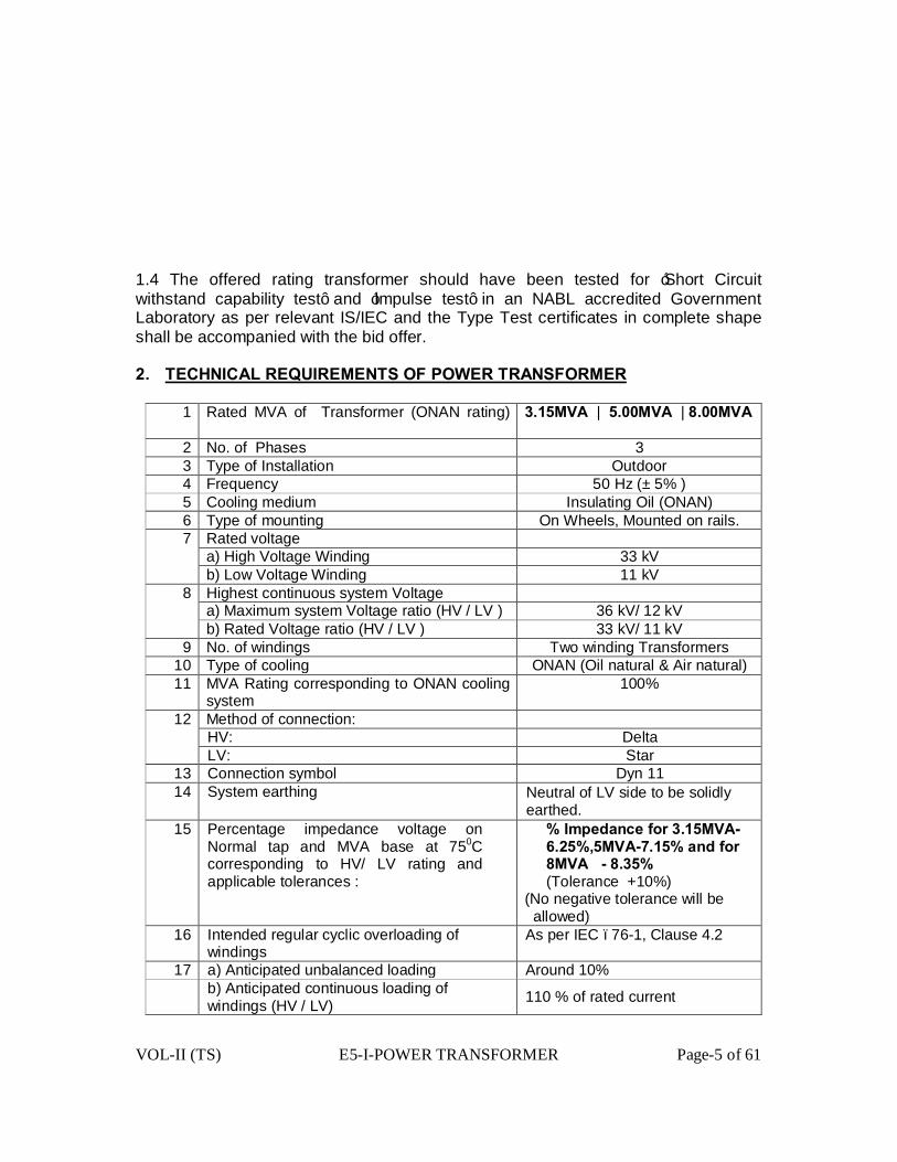
VOL-II (TS) E5-I-POWER TRANSFORMER Page-5 of 61
1.4 The offered rating transformer should have been tested for ‘Short Circuit withstand capability test’ and ‘Impulse test’ in an NABL accredited Government Laboratory as per relevant IS/IEC and the Type Test certificates in complete shape shall be accompanied with the bid offer. 2. TECHNICAL REQUIREMENTS OF POWER TRANSFORMER
1 Rated MVA of Transformer (ONAN rating)
3.15MVA | 5.00MVA | 8.00MVA
2 No. of Phases 3 3 Type of Installation Outdoor 4 Frequency 50 Hz (± 5% ) 5 Cooling medium Insulating Oil (ONAN) 6 Type of mounting On Wheels, Mounted on rails. 7 Rated voltage a) High Voltage Winding 33 kV b) Low Voltage Winding 11 kV
8 Highest continuous system Voltage a) Maximum system Voltage ratio (HV / LV ) 36 kV/ 12 kV b) Rated Voltage ratio (HV / LV ) 33 kV/ 11 kV
9 No. of windings Two winding Transformers 10 Type of cooling ONAN (Oil natural & Air natural) 11 MVA Rating corresponding to ONAN cooling
system 100%
12 Method of connection: HV: Delta LV: Star
13 Connection symbol Dyn 11 14 System earthing Neutral of LV side to be solidly
earthed. 15 Percentage impedance voltage on
Normal tap and MVA base at 750C corresponding to HV/ LV rating and applicable tolerances :
% Impedance for 3.15MVA-6.25%,5MVA-7.15% and for 8MVA - 8.35% (Tolerance +10%)
(No negative tolerance will be allowed)
16 Intended regular cyclic overloading of windings
As per IEC –76-1, Clause 4.2
17 a) Anticipated unbalanced loading Around 10% b) Anticipated continuous loading of
windings (HV / LV) 110 % of rated current
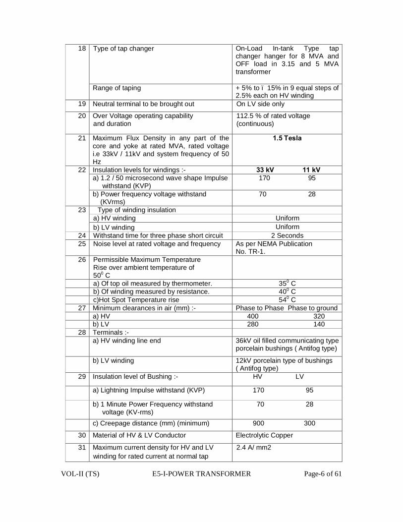
VOL-II (TS) E5-I-POWER TRANSFORMER Page-6 of 61
18 Type of tap changer On-Load In-tank Type tap changer hanger for 8 MVA and OFF load in 3.15 and 5 MVA transformer
Range of taping + 5% to – 15% in 9 equal steps of 2.5% each on HV winding
19 Neutral terminal to be brought out On LV side only
20 Over Voltage operating capability and duration
112.5 % of rated voltage (continuous)
21 Maximum Flux Density in any part of the core and yoke at rated MVA, rated voltage i.e 33kV / 11kV and system frequency of 50 Hz
1.5 Tesla
22 Insulation levels for windings :- 33 kV 11 kV a) 1.2 / 50 microsecond wave shape Impulse
withstand (KVP) 170 95
b) Power frequency voltage withstand (KVrms)
70 28
23 Type of winding insulation a) HV winding Uniform b) LV winding Uniform
24 Withstand time for three phase short circuit 2 Seconds 25 Noise level at rated voltage and frequency As per NEMA Publication
No. TR-1. 26 Permissible Maximum Temperature
Rise over ambient temperature of 500 C
a) Of top oil measured by thermometer. 350 C b) Of winding measured by resistance. 400 C c)Hot Spot Temperature rise 540 C
27 Minimum clearances in air (mm) :- Phase to Phase Phase to ground a) HV 400 320 b) LV 280 140
28 Terminals :- a) HV winding line end 36kV oil filled communicating type
porcelain bushings ( Antifog type)
b) LV winding 12kV porcelain type of bushings ( Antifog type)
29 Insulation level of Bushing :- HV LV
a) Lightning Impulse withstand (KVP) 170 95
b) 1 Minute Power Frequency withstand voltage (KV-rms)
70 28
c) Creepage distance (mm) (minimum) 900 300
30 Material of HV & LV Conductor Electrolytic Copper
31 Maximum current density for HV and LV winding for rated current at normal tap
2.4 A/ mm2

VOL-II (TS) E5-I-POWER TRANSFORMER Page-7 of 61
32 Polarisation Index i.e ratio of Megger values at 600 sec. to 60 sec for HV to earth, L.V to earth and HV to LV
Shall be greater than or equal to 1.5, but less than or equal to ‘5’.
33 Core Assembly Boltless type 34 Temperature Indicator
a) Oil One number b) Winding One number
35 Maximum permissible no load loss at rated voltage and rated frequency.
3.15MVA-3.0 KW (Maximum) 5.0MVA- 3.6. KW (Maximum) 8.0MVA- 4.5KW (Maximum)
36 Maximum permissible load loss at rated current,at normal tap and at 750 C
3.15MVA-17.0 KW (Maximum) 5.0MVA- 21.0. KW (Maximum) 8.0MVA- 38.0KW (Maximum)
37 Paper Covering thickness of HV Winding Conductor 0.6 mm( minimum )
38 Paper Covering thickness of LV Winding Conductor
0.5 mm( minimum )
39 Clearances:- a) Gap between HV Coil to the inside of the
tank on the longer side 65 mm( minimum )
b) Gap between HV Coil to the inside of the tank on the width side (LV Side) 65 mm( minimum )
c) Gap between HV Coil to the inside of the tank on the width side (HV Side to accommodate delta and tapping leads )
115 mm( minimum )
d) Gap between Core yoke to tank bottom 55 mm( minimum ) e) Yoke insulation at top and bottom 130 mm( minimum ) f) Phase to Phase clearance between HV
Limbs 20 mm( minimum )
g) Radial Clearance between LV and HV Coil
20 mm( minimum )
h) Radial Clearance between Core to LV Coil 12.5 mm( minimum ) 40 The difference of Ampere Turns at each location shall not be more than 5 % at all
percentages of tappings 41 Winding to winding clearance should have minimum 20% of sum of pressboard
Cylinder/Barrier. 42 Tap changing gear:- (i) Type- In Tank,High Speed Resistor Type (ii) Provided on HV Side (iii) Tap range -15% to +5%
(iv) Tap Step 2.5% of 33kV (v) Minimum Rated current For 3.15MVA-100A,5MVA-150A &8MVA-200A (vi) Minimum Rated short circuit current 3KA
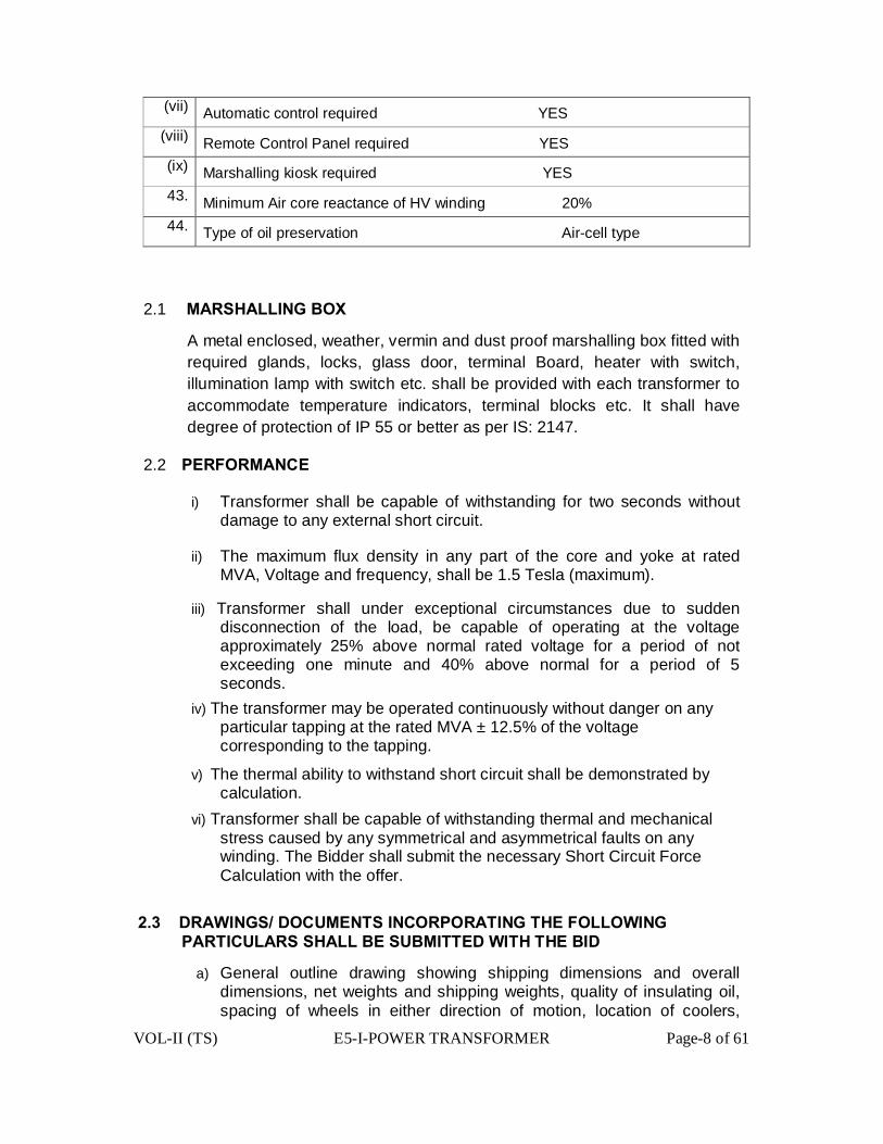
VOL-II (TS) E5-I-POWER TRANSFORMER Page-8 of 61
(vii) Automatic control required YES (viii) Remote Control Panel required YES (ix) Marshalling kiosk required YES 43. Minimum Air core reactance of HV winding 20% 44. Type of oil preservation Air-cell type
2.1 MARSHALLING BOX
A metal enclosed, weather, vermin and dust proof marshalling box fitted with required glands, locks, glass door, terminal Board, heater with switch, illumination lamp with switch etc. shall be provided with each transformer to accommodate temperature indicators, terminal blocks etc. It shall have degree of protection of IP 55 or better as per IS: 2147.
2.2 PERFORMANCE
i) Transformer shall be capable of withstanding for two seconds without damage to any external short circuit.
ii) The maximum flux density in any part of the core and yoke at rated MVA, Voltage and frequency, shall be 1.5 Tesla (maximum).
iii) Transformer shall under exceptional circumstances due to sudden disconnection of the load, be capable of operating at the voltage approximately 25% above normal rated voltage for a period of not exceeding one minute and 40% above normal for a period of 5 seconds.
iv) The transformer may be operated continuously without danger on any particular tapping at the rated MVA ± 12.5% of the voltage corresponding to the tapping.
v) The thermal ability to withstand short circuit shall be demonstrated by calculation.
vi) Transformer shall be capable of withstanding thermal and mechanical stress caused by any symmetrical and asymmetrical faults on any winding. The Bidder shall submit the necessary Short Circuit Force Calculation with the offer.
2.3 DRAWINGS/ DOCUMENTS INCORPORATING THE FOLLOWING PARTICULARS SHALL BE SUBMITTED WITH THE BID
a) General outline drawing showing shipping dimensions and overall dimensions, net weights and shipping weights, quality of insulating oil, spacing of wheels in either direction of motion, location of coolers,
VOL-II (TS) E5-I-POWER TRANSFORMER Page-9 of 61
marshalling box and tap changers etc.
b) Assembly drawings of core, windings etc. and weights of main components / parts.
c) Height of center line on HV and LV connectors of transformers from the rail top level.
d) Dimensions of the largest part to be transported. e) GA drawings / details of various types of bushing f) Tap changing and Name Plate diagram g) Type test certificates of the quoted rating transformer. h) Illustrative & descriptive literature of the Transformer. i) The drawings and Type Test certificates of On-Load Tap Changer j) Maintenance and Operating Instructions. k) The Type Test certificates in complete shape for ‘Lightning Impulse’ and
‘Short Circuit’ Test and Temperature Rise Test
2.4 MISCELLANEOUS
i) Padlocks along with duplicate keys as asked for various valves, marshalling box etc. shall be supplied by the contractor, wherever locking arrangement is provided.
ii) Foundation bolts for wheel locking devices of Transformer shall be supplied by the Contractor.
2.5 DELIVERY The full quantity of the equipments shall be delivered as per the delivery schedule appended to this specification.
2.6 SCHEDULES
Any Schedule, if any, annexed to the specification shall be duly filled by the bidder separately.
2.7 NAME PLATE
Transformer rating plate shall contain the information as given in clause 15 of IS-2026 (part-I). The details on rating plate shall be finalized during the detailed engineering. Further, each transformer shall have inscription of DISTCOM’s name which will be intimated by OPTCL to the firm before hand.
The name plate shall also include
(i) The short circuit rating
(ii) Measured no load current and no load losses at rated voltage and rated frequency
(iii) Measured load losses at 750 C ( Normal Tap only )

VOL-II (TS) E5-I-POWER TRANSFORMER Page-10 of 61
(iv) D.C resistance of each winding at 750 C.
3.0 SYSTEM CONDITIONS
The equipment shall be suitable for installation in supply systems of the following
characteristics.
33 kV 11 kV
1 Frequency 50 Hz ± 5% 50 Hz ± 5%
2 Nominal system voltages 33 kV 11 kV
3 Maximum system voltages 36.3 kV 12 kV
4 Nominal short circuit level AS per IS:2026
5 Insulation levels (1.2/50 µ sec impulse withstand voltage)
170 kV (peak) 95kV (peak)
6 Power frequency with one minute withstand (wet & dry) voltage
70 kV(rms) 28 kV(rms)
7 Neutral earthing arrangements - Solidly earthed
4 CODES & STANDARDS
4.1 The design, material, fabrication, manufacture, inspection, testing before dispatch and performance of power transformers at site shall comply with all currently applicable statutory regulations and safety codes in the locality where the equipment will be installed. The equipment shall also conform to the latest applicable standards and codes of practice. Nothing in this specification shall be construed to relieve the Contractor of this responsibility.
4.2The equipment and materials covered by this specification shall conform to the latest applicable provision of the following standards.
1 IS: 5 Colour for ready mixed paints & Enamels
2 IS: 325 Three Phase Induction Motors 3 IS: 335 New insulating oil for transformers,
switch gears
VOL-II (TS) E5-I-POWER TRANSFORMER Page-11 of 61
4 IS: 1271 Classification of insulating materials for electrical machinery and apparatus in relation to their stability in services
5 IS: 2026(Part I to IV Power Transformer
6 IS: 2071 Method of high voltage testing
7 IS: 2099 High voltage porcelain bushings
8 IS: 2147 Degree of protection
9 IS: 2705 Current Transformers 10 IS: 3202 Code of practice for climate proofing
of electrical equipment 11 IS: 3347 Dimensions for porcelain
Transformer Bushings
12 IS: 3637 Gas operated relays 13 IS: 3639 Fittings and accessories for power
Transformers
14 IS: 5561 Electric Power Connectors 15 IS: 6600/BS:CP’ 10:0 Guide for loading of oil immersed
Transformers 16 IS: 10028 Code of practice for selection,
installation and maintenance of transformers, Part I. II and III
17 IS 1002/1981 (Part – III) Maintance of Transformer
18 C.B.I.P. Publication Manual on Transformers
If the standard is not quoted for any item, it shall be presumed that the latest version of Indian Standard shall be applicable to that item.
The equipment complying other internationally accepted standards, may also be considered if they ensure performance superior to the Indian Standards.
4.3 DRAWINGS
a) The contractor shall furnish, within fifteen days after issuing of Letter of Award. Six copies each of the following drawings/documents incorporating the transformer rating for approval.
i) Detailed overall general arrangement drawing showing front and side elevations and plan of the transformer and all accessories including radiators and external features with details of dimensions, spacing of wheels in either direction of motion, net weights and shipping weights, crane lift for un-tanking, size of lugs and eyes, bushing lifting

VOL-II (TS) E5-I-POWER TRANSFORMER Page-12 of 61
dimensions, clearances between HV and L.V terminals and ground, quantity of insulating oil etc.
ii) Assembly drawings of core and winging and weights of main components / parts. In the Core-Coil assembly drawing , the following dimensions should be clearly mentioned:-
Core:- Window Height, Leg Centre, Core diameter, Grade & thickness of Core material, gross & net Core Cross-Sectional area, Watt loss per kg at the quoted flux density, VA per kg at the quoted flux density.
HV & LV Windings: - Conductor Size (both bare and insulated), Inside and Outside diameters, axial heights, type of windings, No. of spacers with sizes, No. of discs, No. of turns/disc, gap between discs ,clearance from top and bottom yoke, gap between windings, Size of the conductor for delta connection etc.
iii) Foundation plan showing loading on each wheel land jacking points with respect to Centre line of transformer.
iv) GA drawings details of bushing and terminal connectors.
v) Name plate drawing with terminal marking and connection diagrams. vi) Wheel locking arrangement drawing. vii) Transportation dimensions drawings.
viii) Magnetization characteristic curves of PS class neutral and phase
side current transformers, if applicable.
ix) Interconnection diagrams. x) Over fluxing withstand time characteristic of transformer. xi) GA drawing of marshalling box. xii) Control scheme/wiring diagram of marshalling box.
xiii) Technical leaflets of major components and fittings. xiiv) As built drawings of schematics, wiring diagram etc.
xv) Setting of oil temperature indicator, winding temperature indicator. xvi) Completed technical data sheets.
xvii) Detail Drawings,Type Test Certificates including write-up of On-Load tap changing gear and its required accessories/equipments,wiring diagrams etc. as per this specification.
xviii) HV conductor bushing. xix) Bushing Assembly.
xx) Bi-metallic connector suitable for connection to 100 sq. mm
up to 232 Sq.mm AAAC Conductor.
VOL-II (TS) E5-I-POWER TRANSFORMER Page-13 of 61
xxi) GA of LV cable Box. xxii) Radiator type assembly xxiii) Specific loss(watt/Kg. vs.Flux density),VA/Kg.vs.Flux density &B-H Graph for the offered HIB or better core material,to be used for the offered transformer b) All drawings, documents, technical data sheets and test
certificates, results and calculations shall be furnished. c) Ampere –Turns Calculation at various locations and tapping
positions of both LV and HV windings.
4.4 Any approval given to the detailed drawings by the OPTCL shall not relieve the contractor of the responsibility for correctness of the drawing and in the manufacture of the equipment. The approval given by the OPTCL shall be general with overall responsibility with contractor.
5. GENERAL CONSTRUCTIONAL FEATURES
5.1 All material used shall be of best quality and of the class most suitable for working under the conditions specified and shalthe various parts for the work which they have to perform.
5.2 Similar parts particularly removable ones shall be interchangeable.
5.3 Pipes and pipe fittings, screws, studs, nuts and bolts used for external Connections shall be as per the relevant standards. Steel bolts and nuts exposed to atmosphere shall be galvanized.
5.4 Nuts, bolts and pins used inside the transformers and tap changer compartments shall be provided with lock washer or locknuts.
5.5 Exposed parts shall not have pockets where water can collect.
5.6 Internal design of transformer shall ensure that air is not trapped in any location.
5.7 Material in contact with oil shall be such as not to contribute to the formation of acid in oil. Surface in contact with oil shall not be galvanized or cadmium plated.
5.8 Labels, indelibly marked, shall be provided for all identifiable accessories like
Relays, switches current transformers etc. All label plates shall be of in corrodible material.
5.9 All internal connections and fastenings shall be capable of operating under overloads and over-excitation, allowed as per specified stands without injury.
5.10 Transformer and accessories shall be designed to facilitate proper operation, inspection, maintenance and repairs.

VOL-II (TS) E5-I-POWER TRANSFORMER Page-14 of 61
5.11 No patching, plugging, shimming or other such means of overcoming defects, discrepancies or errors will be accepted.
5.12 Schematic Drawing of the wiring, including external cables shall be put under the prospane sheet on the inside door of the transformer marshalling box.
5.13 Painting Particular attention shall be paid to the following:
a) Proper storage to avoid exposure as well as extremes of temperature. b) Surface preparation prior to painting. c) Mixing and thinning d) Application of paints and the recommended limit on time intervals
between coats. e) Shelf life for storage.
5.13.1.1 All paints, when applied in normal full coat, shall be free from runs, sags, wrinkles, patchiness, brush marks or other defects.
5.13.1.2 All primers shall be well marked into the surface, particularly in areas where painting is evident, and the first priming coat shall be applied as soon as possible after cleaning. The paint shall be applied by airless spray according to the manufacturer’s recommendations. However, wherever airless spray is not possible, conventional spray be used with prior approval of OPTCL.
5.13.1.3 The supplier shall, prior to painting protect nameplates, lettering gauges, sight glasses, light fittings and similar such items.
5.13.2 Cleaning and Surface Preparation
5.13.2.1 After all machining, forming and welding has been completed, all steel work surfaces shall be thoroughly cleaned of rust, scale, welding slag or spatter and other contamination prior to any painting.
5.13.2.2 Steel surfaces shall be prepared by Sand/Shot blast cleaning and Chemical cleaning by Seven tank process including Phosphating to the appropriate quality.The surface shall be treated by phosphating and dried in accordance with IS 6005(Code of practices for phosphating of Iron and Steel). Immediately after Phosphating, surface shall be given two coats of high quality Zinc Chromate Primer.
VOL-II (TS) E5-I-POWER TRANSFORMER Page-15 of 61
5.13.2.3 The pressure and Volume of the compressed air supply for the blast cleaning shall meet the work requirements and shall be sufficiently free from all water contamination prior to any painting.
5.13.2.4 Chipping, scraping and steel wire brushing using manual or power driven tools cannot remove firmly adherent mill-scale and shall only be used where blast cleaning is impractical.
5.13.3 Protective Coating
As soon as all items have been cleaned and within four hours of the subsequent drying, they shall be given suitable anticorrosion protection.
5.13.4 Paint Material
Followings are the type of paints that may be suitably used for the items to be painted at shop and supply of matching paint to site:
i) Heat resistant paint (Hot oil proof) for inside surface.
ii) For external surfaces one coat of Thermo Setting Paint or 2 coats of Zinc chromate followed by 2 coats of POLYURETHANE . The color of the finishing coats shall be dark admiral grey conforming to No.632 or IS 5:1961.
5.13.5 Painting Procedure
5.13.5.1 Al painting shall be carried out in conformity with both specifications and with the paint manufacture’s recommendations. All paints in any one particular system. Whether shop or site applied, shall originate from one paint manufacturer.
5.13.5.2 Particular attention shall be paid to the manufacture’s instructions on storage, mixing, thinning and pot life. The paint shall only be applied in the manner detailed by the manufacturer e.g. brush, roller, conventional or airless spray and shall be applied under the manufacturer’s recommended conditions. Minimum and maximum time intervals between coats shall be closely followed.
5.13.5.3 All prepared steel surfaces should be primed before visible re-rusting occurs or within 4 hours whichever is sooner. Chemical treated steel surfaces shall be primed as soon as the surface is dry and while the surface is warm.
5.13.5.4 Where the quality of film is impaired by excess film thickness,(wrinkling, mud cracking or general softness) the supplier shall remove the unsatisfactory paint coatings and apply another. As a general rule, dry film thickness should not exceed the specified minimum dry film thickness
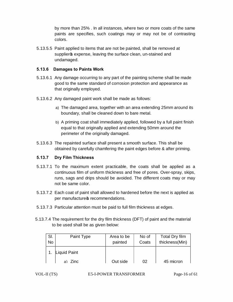
VOL-II (TS) E5-I-POWER TRANSFORMER Page-16 of 61
by more than 25% . In all instances, where two or more coats of the same paints are specifies, such coatings may or may not be of contrasting colors.
5.13.5.5 Paint applied to items that are not be painted, shall be removed at supplier’s expense, leaving the surface clean, un-stained and undamaged.
5.13.6 Damages to Paints Work
5.13.6.1 Any damage occurring to any part of the painting scheme shall be made good to the same standard of corrosion protection and appearance as that originally employed.
5.13.6.2 Any damaged paint work shall be made as follows:
a) The damaged area, together with an area extending 25mm around its boundary, shall be cleaned down to bare metal.
b) A priming coat shall immediately applied, followed by a full paint finish equal to that originally applied and extending 50mm around the perimeter of the originally damaged.
5.13.6.3 The repainted surface shall present a smooth surface. This shall be obtained by carefully chamfering the paint edges before & after priming.
5.13.7 Dry Film Thickness
5.13.7.1 To the maximum extent practicable, the coats shall be applied as a continuous film of uniform thickness and free of pores. Over-spray, skips, runs, sags and drips should be avoided. The different coats may or may not be same color.
5.13.7.2 Each coat of paint shall allowed to hardened before the next is applied as per manufacture’s recommendations.
5.13.7.3 Particular attention must be paid to full film thickness at edges.
5.13.7.4 The requirement for the dry film thickness (DFT) of paint and the material to be used shall be as given below:
Sl. No
Paint Type Area to be painted
No of Coats
Total Dry film thickness(Min)
1. Liquid Paint
a) Zinc Out side 02 45 micron
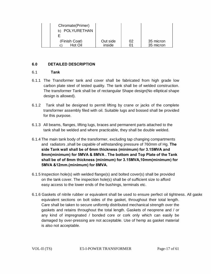
VOL-II (TS) E5-I-POWER TRANSFORMER Page-17 of 61
Chromate(Primer) b) POLYURETHANE
(Finish Coat) Out side 02 35 micron c) Hot Oil inside 01 35 micron
6.0 DETAILED DESCRIPTION
6.1 Tank
6.1.1 The Transformer tank and cover shall be fabricated from high grade low carbon plate steel of tested quality. The tank shall be of welded construction. The transformer Tank shall be of rectangular Shape design(No elliptical shape design is allowed).
6.1.2 Tank shall be designed to permit lifting by crane or jacks of the complete transformer assembly filed with oil. Suitable lugs and bossed shall be provided for this purpose.
6.1.3 All beams, flanges, lifting lugs, braces and permanent parts attached to the tank shall be welded and where practicable, they shall be double welded.
6.1.4 The main tank body of the transformer, excluding tap changing compartments and radiators ,shall be capable of withstanding pressure of 760mm of Hg. The side Tank wall shall be of 6mm thickness (minimum) for 3.15MVA and 8mm(minimum) for 5MVA & 8MVA . The bottom and Top Plate of the Tank shall be of of 8mm thickness (minimum) for 3.15MVA,10mm(minimum) for 5MVA &12mm.(minimum) for 8MVA.
6.1.5 Inspection hole(s) with welded flange(s) and bolted cover(s) shall be provided on the tank cover. The inspection hole(s) shall be of sufficient size to afford easy access to the lower ends of the bushings, terminals etc.
6.1.6 Gaskets of nitrile rubber or equivalent shall be used to ensure perfect oil tightness. All gaskets shall be closed design (wiequivalent sections on bolt sides of the gasket, throughout their total length. Care shall be taken to secure uniformly distributed mechanical strength over the gaskets and retains throughout the total length. Gaskets of neoprene and / or any kind of impregnated / bonded core or cork only which can easily be damaged by over-pressing are not acceptable. Use of hemp as gasket material is also not acceptable.
VOL-II (TS) E5-I-POWER TRANSFORMER Page-18 of 61
6.1.7 Suitable guides shall be provided for positioning the various parts during assemble or dismantling. Adequate space shall be provided between the cores and windings and the bottom of the tank for collection of any sediment.
6.2 Tank Cover
The transformer top shall be provided with a detachable tank cover with bolted flanged gasket joint. Lifting lugs shall be provided for removing the cover. The surface of the cover shall be suitable sloped so that it does not retain rain water.
6.3 UNDER CARRIAGE
6.3.1 The transformer tank shall be supported on steel structure with detachable plain rollers completely filled with oil. Suitablecorrosion and shall be equipped with fittings for lubrication. It shall be possible to swivel the wheels in two directions, at right angle to or parallel to the main axis of the transformers.
6.4 CORE
6.4.1 Stage inspection for core construction shall be carried out by the Purchaser.
6.4.2 Each lamination shall be insulated such that it will not deteriorate due to mechanical pressure and the action of hot transformer oil.
6.4.3 The core shall be constructed from high grade, non-aging Cold Rolled Grain Oriented (CRGO) silicon steel laminations conforming to HIB grade or better grade with lamination thickness not more than 0.23mm to 0.27mm. The maximum flux density in any part of the cores and yoke at normal voltage and frequency shall not be more than 1.5 Tesla. The Bidder shall provide saturation curve of the core material, proposed to be used. Laminations of different grade(s) and different thickness (s) are not allowed to be used in any manner or under any circumstances.
6.4.4 The bidder should offer the core for inspection starting from the destination port to enable OPTCL for deputing inspecting officers for detail verification as given below and approval by the OPTCL during the manufacturing stage. Bidder’s call notice for the purpose should be accompanied with the following documents as applicable as a proof towards use of prime core material: The core coils, if found suitable, are to be sealed with proper seals which shall be opened in presence of the inspecting officers during core- cutting at the manufacturer’s or it’s sub-vendor’s premises as per approved design drawing.
a) Purchase Order No. & Date.
b) Invoice of the supplier
c) Mills test certificate

VOL-II (TS) E5-I-POWER TRANSFORMER Page-19 of 61
d) Packing list
e) Bill of lading
f) Bill of entry certificate to customs
Core material shall be directly procured either from the manufacturer or through their accredited marketing organization of repute, but not through any agent.
6.4.4 (B) For Transformer Manufacturer (TM), who has in-house core-cutting facility, the packed core coils shall be verified at their works as per followings along with witnessing of corea) Purchase Order No. & Date ; b) No. of packed coils with Package Nos. c) Gross Weight. d) Net Weight : e) Port of loading. f) Port of Discharge ; g) Name of the Ocean Vessel : h) Grade & Thickness of Core Material : i) Any other information as mentioned on the body of packed coils.
6.4.4 ( C ) For those bidders, who have no in-house core-cutting facility, they should mention the names of at least three sub-vendors to whom they intend to assign their core-cutting. Such sub-vendors should have been approved by other Electricity Board / Electrical Utilities and accredited by some internationally recognized certification body like ISO- 9000 etc. to ensure that a minimum quality parameters & tolerance are maintained. The experience, the details of core-cutting facilities finishing & testing facilities etc. as available which such sub-vendors should be clearly out-lined in the bid
6.4.4 (D) On award of Contract the TM is to assign the core-cutting to such sub-
vendors for which approval is to be given by the OPTCL. 6.4.5 The laminations shall be free of all burrs and sharp projections. Each sheet
shall have an insulting coating resistant to the action of hot oil.
6.4.6 The insulation structure for the core to bolts and core to clamp plates, shall be such as to withstand 2000 V DC voltage for one minute.
6.4.7 The completed core and coil shall be so assembled that the axis and the plane of the outer surface of the core assemble shall not deviate from the vertical plane by more than 25mm.
6.4.8 All steel sections used for supporting the core shall be thoroughly shot or sand blasted, after cutting, drilling and welding.
VOL-II (TS) E5-I-POWER TRANSFORMER Page-20 of 61
6.4.9 The finally assembled core with all the clamping structures shall be free from deformation and shall not vibrate during operation.
6.4.10 The core clamping structure shall be designed to minimize eddy current loss.
6.4.11 The framework and clamping arrangements shall be securely earthed.
6.4.12 The core shall be carefully assembled and rigidly clamped to ensure adequate mechanical strength.
6.4.13 Oil ducts shall be provided, where necessary, to ensure adequate cooling inside the core. The welding structure and major insulation shall not obstruct the free flow of oil through such ducts.
6.4.14 The design of magnetic circuit shall be such as to avoid static discharges, development of short circuit paths within itself or to the earth clamping structure and production of flux component at right angle to the plane of the lamination, which may cause local heating. The supporting framework of the cores shall be so designed as to avoid the presence of pockets, which would prevent complete emptying of the tank through the drain valve or cause trapping of air during filling.
6.4.15 The construction is to be of boltless core type. The core shall be provided with lugs suitable for lifting the complete core and coil assembly. The core and coil assemble shall be so fixed in the tank that shifting will not occur during transport or short circuits.
6.4.16 The temperature gradient between core & surrounding oil shall be maintained less than 20 deg. Centigrade. The manufacturer shall demonstrate this either through test ( procedure to be mutually agreed) or by calculation.
6.5 INTERNAL EARTHING
6.5.1 All internal metal parts of the transformer, with the exception of individual laminations and their individual clamping plates shall be earthed.
6.5.2 The top clamping structure shall be connected to the tank by a copper strap. The bottom clamping structure shall be earthed by one or more the following methods:
a) By connection through vertical tie-rods to the top structure.
b) By direct metal to metal contact with the tank base.
c) By a connection to the structure on the same side of the core as the main earth connection to the tank.

VOL-II (TS) E5-I-POWER TRANSFORMER Page-21 of 61
6.5.3 The magnetic circuit shall be connected to the clamping structure at one point only and this shall be brought out of the top cover of the transformer tank through a suitably rated insulator. A disconnecting link shall be provided on transformer tank to facilitate disconnections from ground for IR measurement purpose.
6.5.4 Coil clamping rings of metal at earth potential shall be connected to the adjacent core clamping structure on the same side as the main earth connections.
6.6 WINDING:-
6.6.1 Winding shall be subjected to a shrinking and seasoning process, so that no further shrinkage occurs during service. Adjustable devices shall be provided for taking up possible shrinkage in service.
6.6.2 All low voltage windings for use in the circular coil concentric winding shall be wound on a performed insulating cylinder for mechanical protection of the winding in handling and placing around the core.
6.6.3 Winding shall not contain sharp bends which might damage the insulation or produce high dielectric stresses. No strip conductor wound on edge shall have width exceeding six times the thickness.
6.6.4 Materials used in the insulation and assembly of the windings shall be insoluble, non catalytic and chemically inactive in the hot transformer oil and shall not soften or the otherwise affected under the operating conditions.
6.6.5 Varnish application on coil windings may be given only for mechanical protection and not for improvement in dielectric properties. In no case varnish or other adhesive be used which will seal the coil and prevent evacuation of air and moisture and impregnation by oil.
6.6.6 Winding and connections shall be braced to withstand shocks during transport or short circuit.
6.6.7 Permanent current carrying joints in the windings and leads shall be welded or brazed. Clamping bolts for current carrying parts inside oil shall be made of oil resistant material which shall not be affected by acidity in the oil steel bolts, if used, shall be suitably treated.
6.6.8 Terminals of all windings shall be brought out of the tank through bushings for external connections.
6.6.8.1The completed core and coil assemble shall be dried in vacuum at not more than 0.5mm of mercury absolute pressure and shall be immediately impregnated with oil after the drying process to ensure the evacuum over or in the transformer tank.
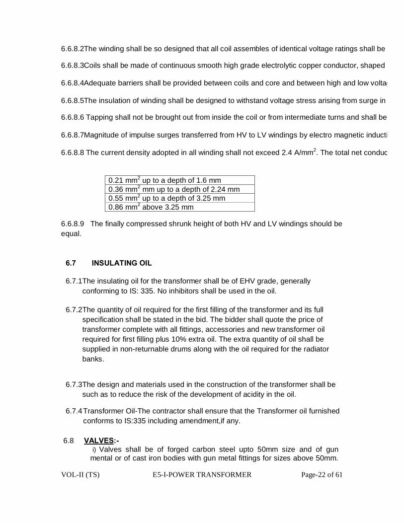
VOL-II (TS) E5-I-POWER TRANSFORMER Page-22 of 61
6.6.8.2The winding shall be so designed that all coil assembles of identical voltage ratings shall be interchangeable and field repa
6.6.8.3Coils shall be made of continuous smooth high grade electrolytic copper conductor, shaped and braced to provide for expansion and co
6.6.8.4Adequate barriers shall be provided between coils and core and between high and low voltage coil. End turn shall have additional protection against abnormal line disturbances.
6.6.8.5The insulation of winding shall be designed to withstand voltage stress arising from surge in transmission lines due to atmos
6.6.8.6 Tapping shall not be brought out from inside the coil or from intermediate turns and shall be so arranged as to preserve as f
6.6.8.7Magnitude of impulse surges transferred from HV to LV windings by electro magnetic induction and capacitance coupling shall be limited to BIL of L
6.6.8.8 The current density adopted in all winding shall not exceed 2.4 A/mm2. The total net conductor area should be
0.21 mm2 up to a depth of 1.6 mm 0.36 mm2 mm up to a depth of 2.24 mm 0.55 mm2 up to a depth of 3.25 mm 0.86 mm2 above 3.25 mm
6.6.8.9 The finally compressed shrunk height of both HV and LV windings should be equal.
6.7 INSULATING OIL
6.7.1 The insulating oil for the transformer shall be of EHV grade, generally conforming to IS: 335. No inhibitors shall be used in the oil.
6.7.2 The quantity of oil required for the first filling of the transformer and its full specification shall be stated in the bid. The bidder shall quote the price of transformer complete with all fittings, accessories and new transformer oil required for first filling plus 10% extra oil. The extra quantity of oil shall be supplied in non-returnable drums along with the oil required for the radiator banks.
6.7.3 The design and materials used in the construction of the transformer shall be such as to reduce the risk of the development of acidity in the oil.
6.7.4 Transformer Oil-The contractor shall ensure that the Transformer oil furnished conforms to IS:335 including amendment,if any.
6.8 VALVES:-
i) Valves shall be of forged carbon steel upto 50mm size and of gun mental or of cast iron bodies with gun metal fittings for sizes above 50mm.
VOL-II (TS) E5-I-POWER TRANSFORMER Page-23 of 61
They shall be of full way type with screwed ends and shall be opened by turning counter clockwise when facing the hand wheel. There shall be no oil leakage when the valves are in closed position.
ii) Each valve shall be provided with an indicator to show the open and closed positions and shall be provided with facility for padlocking in either open or closed position. All screwed valves shall be furnished with pipe plugs for protection. Padlocks with duplicate keys shall be supplied along with the valves.
iii) All valves except screwed valves shall be provided with flanges having machined faced drilled to suit the applicable requirements, Oil tight blanking plates shall be provided for each connection for use when any radiator is detached and for all valves opening to atmosphere. If any special radiator valve tools are required the contractor shall supply the same.
i)Each transformer shall be provided with following valves on the tank:
a) Drain valve so located as to completely drain the tank & to be provided with locking arrangement.
b) Two filter valves on diagonally opposite corners of 50mm size & to be provided with locking arrangement.
c) Oil sampling valves not less than 8mm at top and bottom of main tank & to be provided with locking arrangement.
d) One 15mm air release plug.
e) Valves between radiators and tank.
Drain and filter valves shall be suitable for applying vacuum as specified in this specification.
6.9 ACCESSORIES:-
6.9.1 Bushing
i) All porcelain used in bushings shall be homogeneous, non-porous, uniformly glazed to brown colour and free from blisters, burns and other defects.
ii) Stress due to expansion and contraction in any part of the bushing shall not lead to deterioration.
iii) Bushing shall be designed and tested to comply with the applicable standards.
iv) Bushing rated for 400A and above shall have non-ferrous flanges and hardware.
VOL-II (TS) E5-I-POWER TRANSFORMER Page-24 of 61
v) Fittings made of steel or malleable iron shall be galvanized
vi) Bushing shall be so located on the transformers that full flashover strength will be utilized. Minimum clearances as required for the BIL shall be realized between live parts and live parts to earthed structures.
vii) All applicable routine and type tests certificates of the bushings shall be furnished for approval. viii) Bushing shall be supplied with bi-metallic terminal connector/ clamp/
washers suitable for fixing to bush terminal and the OPTCL’s specified conductors. The connector/clamp shall be rated to carry the bushing rated current without exceeding a temperature rise of 500 C over an ambient of 500C. The connector/clamp shall be designed to be corona free at the maximum rated line to ground voltage.
ix) Bushing of identical voltage rating shall be interchangeable.
x) The insulation class of high voltage neutral bushing shall be properly coordinated with the insulation class of the neutral of the low voltage winding.
xi) Each bushing shall be so coordinated with the transformer insulation that all flashover will occur outside the tank.
6.9.2Protection & Measuring Devices:-
i) Oil Conservator Tank
a) A conservator,complete with drain valve shall be provided in such a position,so as not to obstruct the electrical connections to the Transformer. The capacity of the conservator between highest and lowest visible levels shall be minimum of 7.5% of the total cold oil volume in the Transformer.
b) The conservator tank shall be bolted on its support of mounting to allow for its removal for cleaning/ repairing purposes.
c) The conservator shall be fitted with magnetic oil level gauge with low level electrically insulated alarm contact.
d) The silica gel breather shall have minimum quantity of silica gel as1kg for every 3500Ltrs. of oil in the Tank. The container for the dehydring agent shall be of transparent plastic of best quality,to be approved by OPTCL.
ii) Pressure Relief Device.
The pressure relief device provided shall be of sufficient size for rapid release of any pressure that may be generated in the tank and which may
VOL-II (TS) E5-I-POWER TRANSFORMER Page-25 of 61
result in damage of the equipment. The device shall operate at a static pressure of less than the hydraulic test pressure of transformer tank. It shall be mounted direct on the tank. A pair of electrically insulated contract shall be provided for alarm and tripping.
iii) Buchholz Relay
A double float type Buchholz relay shall be provided., Any gas evolved in the transformer shall collect in this relay. The relay shall be provided with a test cock suitable for a flexible pipe connection for checking its operation. A copper tube shall be connected from the gas collector to a valve located about 1200 mm above ground level to facilitate sampling with the transformer in service. The device shall be provided with two electrically independent potential free contracts, one for alarm on gas accumulation and the other for tripping on sudden rise of pressure.
iv) Temperature Indicator
a) Oil Temperature Indicator (OTI)
The transformers shall be provided with a mercury contact type thermometer with 150 mm dial for top oil temperature indication. The thermometer shall have adjustable, electrically independent potential free alarm and trip contacts. Maximum reading pointer and resetting device shall be mounted in the local control panel. A temperature sensing element suitably located in a pocket on top oil shall be furnished. This shall be connected to the OTI by means of capillary tubing. Accuracy class of OTI shall be ± 1% or better. One No electrical contact capable of operating at 5 A ac at 230 volt supply. b) Winding Temperature indicator(WTI)
A device for measuring the hot spot temperature of the winding shall be provided. It shall comprise the following.
i) Temperature sensing element.
ii) Image Coil.
iii) Mercury contacts.
iv) Auxiliary CTS, If required to match the image coil, shall be furnished and mounted in the local control panel.
v) 150mm dial local indicating instrument with maximum reading pointer mounted in local panel and with adjustable electrically independent ungrounded contacts, besides that required for control of cooling
VOL-II (TS) E5-I-POWER TRANSFORMER Page-26 of 61
equipment, one for high winding temperature alarm and on for trip.
vi) Calibration device.
vii) Two number electrical contact each capable of operating at 5 A ac at 230 Volt supply. 7.9.3 Oil Preservation Equipment
6.9.3.1 :-
The oil preservation shall be diaphragm type oil sealing in conservator to prevent oxidation and contamination of oil due to contact with atmospheric moisture.
The conservator shall be fitted with a dehydrating filter breather. It shall be so designed that.
i) Passage of air is through a dust filter & Silica gel.
ii) Silica gel is isolated from atmosphere by an oil seal.
iii) Moisture absorption indicated by a change in colour of the crystals of the silica gel can be easily observed from a distance.
iv) Breather is mounted not more than 1400 mm above rail top level.
6.10 MARSHALLING BOX:-
i) Sheet steel, weather, vermin and dust proof marshalling box fitted with required glands, locks, glass door, terminal Board, heater with switch, illumination lamp with switch, watertight hinged and padlocked door of a suitable construction shall be provided with each transformer to accommodate temperature indicators, terminal blocks etc. The box shall have slopping roof and the interior and exterior painting shall be in accordance with the specification. Padlock along with duplicate keys shall be supplied for marshalling box. The degree of protection shall be IP-55 or better.
ii) The schematic diagram of the circuitry inside the marshalling box be prepared and fixed inside the door under a suitable sheet.
iii) The marshalling box shall accommodate the following equipment:
a) Temperature indicators.
b) Space for accommodating Control & Protection equipment in future for the cooling fan (for ONAF type cooling, may be provided in future).

VOL-II (TS) E5-I-POWER TRANSFORMER Page-27 of 61
c) Terminal blocks and gland plates for incoming and outgoing cables.
All the above equipments except c) shall be mounted on panels and back of panel wiring shall be used for inter-connection. The temperature indicators shall be so mounted that the dials are not more than 1600 mm from the ground level and the door (s) of the compartment(s) shall be provided with glazed window of adequate size. The transformer shall be erected on a plinth which shall be 2.5 feet above ground level.
iii) To prevent internal condensation, a metal clad heater with thermostat shall be provided. The heater shall be controlled by a MCB of suitable rating mounted in the box. The ventilation louvers, suitably padded with felt, shall also be provided. The louvers shall be provided with suitable felt pads to prevent ingress of dust.
iv) All incoming cables shall enter the kiosk from the bottom and the gland plate shall not be less than 450 mm from the base of the box. The gland plate and associated compartment shall be sealed in suitable manner to prevent the ingress of moisture from the cable trench.
v) The control connection, wiring etc. shall be as per Clause 3.15 of this
6.11 TAPCHANGER 6.11.1 ON-LOAD TAP-CHANGERS WITH REMOTE TAP CHANGE CONTROL
Each transformer shall be provided with an “In-Tank” Type on-load tap-changer
connected to the high voltage winding. The on-load tap-changer shall be
capable of withstanding the voltages described earlier and shall comply with
the requirements of IEC-60214, latest revision. Its tapping range, number of
steps and tap positions shall be as specified.
On Load Tap Changer shall be sourced from reputed manufacturer(s) and it
should be type tested as per relevant IEC60214 as given below and test
methods shall be in full conformance to the procedures indicated in IEC60214
Sl.No. IEC Reference Test Description
1. Cl.5.2.1 Temperature rise of contacts.
VOL-II (TS) E5-I-POWER TRANSFORMER Page-28 of 61
2. Cl.5.2.2 Switching Tests
3. Cl.5.2.3 Short-circuit current Test.
4. Cl.5.2.4 Short-circuit current Test. .
5. Cl.5.2.5 Mechanical tests.
6. Cl.5.2.6 Dielectric Tests
OLTC manufacturer shall conduct the following routine tests fully in compliance
with IEC 60214 on every unit, as given below, before dispatch to assure the
quality of the OLTC.OPTCL at its sole discretion may test-witness and inspect
the Tap-Changers at the works of the OLTC manufacturer.
The following are the routine tests,to be carried out on each OLTC:-
Sl.No. IEC Reference Test Description
1. Cl.5.3.1 Mechanicaql Test.
2. Cl.5.3.2 Sequence test
3. Cl.5.3.3 Auxiliary circuits Insulation tests
4. Cl.5.3.4 Pressure test
5. Cl.5.3.4 Vacuum test
All the test reports shall be submitted to OPTCL for approval.
Adequate access for personnel shall be provided for inspection and
maintenance. The guaranteed interval between maintenance periods for the
diverter switch shall be 10 years or 50,000 operations. It shall not be possible
for oil in the diverter switch compartment to come in contact with the oil in the

VOL-II (TS) E5-I-POWER TRANSFORMER Page-29 of 61
main transformer tank.
The tap-changer shall be driven by a motor operated mechanism incorporating
a stored energy device which shall ensure that once a change of tap begins it is
completed and so shall ensure that the mechanism does not fail in an
intermediate position on loss of the supply voltage to the motor. The motor shall
be rated for 400/230V, 50 Hz and shall operate satisfactorily at any voltage
between 85% and 110% of rated voltage.
A tap-changer mechanism box with hinged door and mounted on the
transformer tank at a convenient height shall contain all electrical and
mechanical parts associated locally with control of the tap-changer. Remote
tap-changer controls shall also be provided at a transformer control panel (one
per transformer, to be supplied under this contract) in the control room.
Facilities for electrical raise and lower operation (Control switch or push button)
as well as mechanical operation shall be provided as the tap-change
mechanism box. An interlock shall be provided which shall interrupt the electric
supply to the drive motor when the manual mechanical operating device is
engaged. The motor drive control shall be such that on initiation of a tap-
change operation by means of a control switch or push-button the tap-changer
shall complete its movement form one service position to an adjacent one
irrespective of whether or not the control switch or push button has been
operated continuously during the running time or motor drive. Another
operation shall only be possible when the previous operation has been

VOL-II (TS) E5-I-POWER TRANSFORMER Page-30 of 61
completed, the control switch or push button has been released and the control
system is again in the rest position.
The tap-changer arrangement shall be such that a command to raise tap-
numbers shall result in an increase in the secondary voltage with constant
voltage applied to the high voltage winding.
An under and over voltage monitoring relay fed with line voltage from the
owner’s voltage transformers on the low voltage side of the transformer and
capable of being set in a continuously variable range from 90% to 115% normal
voltage (110V) shall be used to give visual and audible signals at the remote
tap change control panel if the LV voltage lies above or below preset values.
Limit switches shall be provided to prevent over-running of the tap-change
mechanism. These shall be directly connected in the motor circuit. In addition
mechanical end stops shall be fitted to prevent over-running of the mechanism
under any conditions. A counter shall be provided to indicate the number of tap-
change operations that have been taken place.
A mechanical tap-position indicator shall be provided and it shall be visible from
ground level through a window in the door of the mechanism box. Position
transmitter e.g. dial switches shall be provided to:
a. Signal tap position to the control cabinet in the control room. b. Signal “out of step” under parallel operating conditions. A Remote/Local switch shall be provided at the mechanism box to select either
remote or local operation. When this switch is turned to the Remote position

VOL-II (TS) E5-I-POWER TRANSFORMER Page-31 of 61
control shall be passed to the control cabinet in the control room. It should be
possible to use only one control, i.e. Local or Remote.
It shall be possible to operate a transformer tap-changer independently or in
parallel with the tap-changers of other similar transformers in the same
substation in either a “master” or “follower” mode. In addition, when operating
independently or in parallel in the master mode, it shall be possible to have
manual operation by means of control switch, push button or, (in future)
automatic operation by means of an automatic voltage regulating relay.
Contacts shall be provided for future SCADA control of the tap-changer and for
reporting of the tap position and mode of control to the SCADA system. The
paralleling scheme shall use the in- step principle and shall have provision for
operating singly or in parallel in any combination. It shall be possible for any
transformer in a group to be selected as either the master or follower for that
group when operating in parallel. Each transformer control panel shall therefore
have a manual/automatic control switch or push buttons,
independent/master/follower control switch or push buttons as well as “raise”
and lower” control switches or push buttons. Interlock shall be provided to avoid
independent operation when the transformers are running in parallel. There
should not be any out-of-step during such operation.
The control scheme shall be capable of extension to cater for the total number
of transformers to be installed in any future development of the substation. The
control mode selected shall be indicated on the front of the control cabinet.
Each transformer shall have a miniature circuit breaker (MCB) on the AC
distribution cabinet through which the 400/230V, 50 Hz supply to its tap-
changer and temperature controls is passed. Separate MCB’s shall be provided
at the mechanism box for protection of the motor and control circuits. The
control circuits shall operate at 110V single phase, to be supplied from a
transformer having a ratio of 230/55-0-55 V, with the center point earthed
through a removable link mounted in the marshalling box or tap-changer
VOL-II (TS) E5-I-POWER TRANSFORMER Page-32 of 61
mechanism box.
Each tap-changer mechanism box shall be fitted with an anti-condensation
space heater (230V AC) controlled by a humidistat with variable range. A lamp
for illumination purposes controlled by a door switch shall be provided. Solar
gain can give rise to high temperature within a mechanism box. Adequate
ventilation shall be provided to ensure that all equipment contained therein
shall operate satisfactorily under these conditions.
A terminal block with terminals rated for 10 A continuous current, 650V grade of
moulded insulating materials shall be provided for panel wiring and external
connection.
Ten percent spare terminals shall be provided in each mechanism box.
The tap changer mechanism box shall be outdoor, weatherproof type, dust,
vermin and damp proof with a degree of protection of IP54 of IEC 529 or IS
13947 equivalent.
6.11.2 Transformer Tap Change Control Panel:-
The indoor panel suitable for installation in the owner’s control room mentioned above shall contain. § Raise and Lower push buttons or switch.
§ Independent / master / follower selector switch.
§ Remote tap position indicator.
§ Necessary audible & visual alarms.
§ Out of step relay with two spare contacts ( 2 NO + 2 NC )
In addition to the above the Transformer tap change control panel shall have an audible and visual annunciation system for the following trips and alarms. Oil temperature alarm
Oil temperature trip
Winding temperature alarm
Winding temperature trip
Buchholz alarm
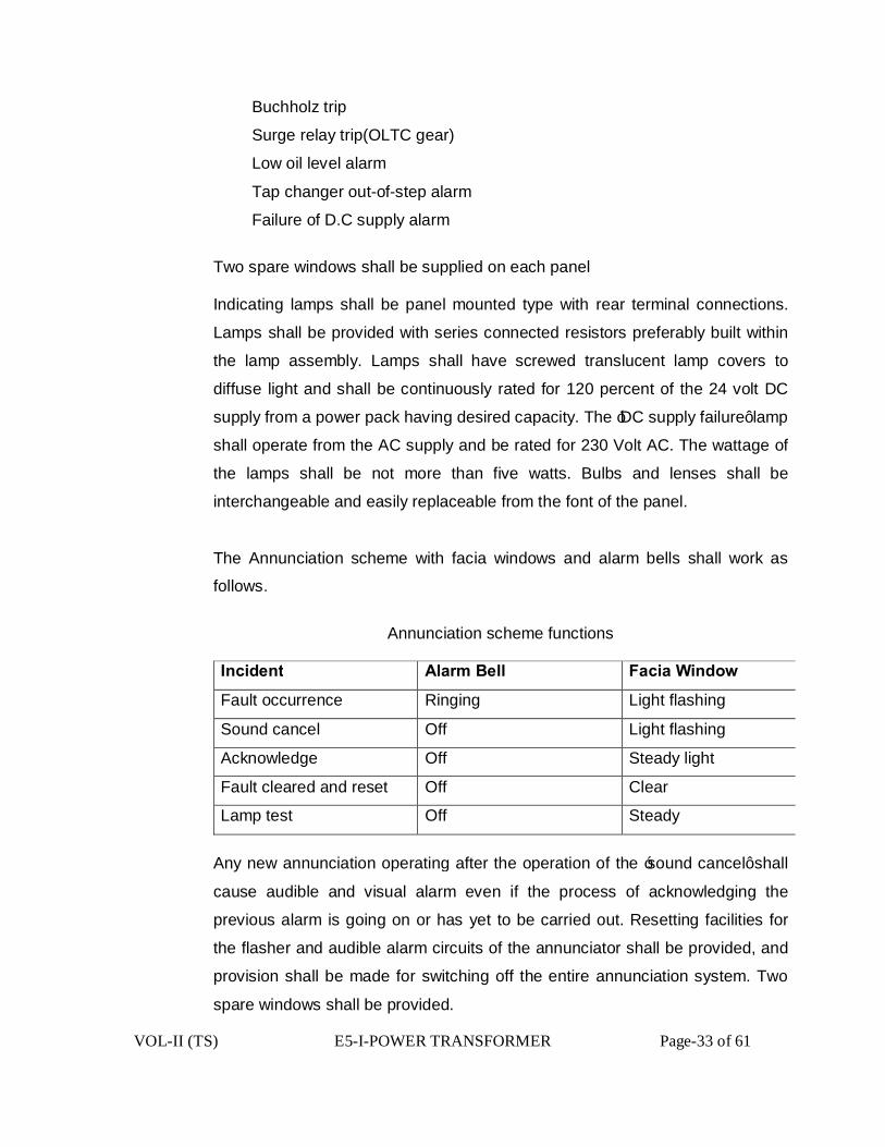
VOL-II (TS) E5-I-POWER TRANSFORMER Page-33 of 61
Buchholz trip
Surge relay trip(OLTC gear)
Low oil level alarm
Tap changer out-of-step alarm
Failure of D.C supply alarm
Two spare windows shall be supplied on each panel Indicating lamps shall be panel mounted type with rear terminal connections.
Lamps shall be provided with series connected resistors preferably built within
the lamp assembly. Lamps shall have screwed translucent lamp covers to
diffuse light and shall be continuously rated for 120 percent of the 24 volt DC
supply from a power pack having desired capacity. The ‘DC supply failure’ lamp
shall operate from the AC supply and be rated for 230 Volt AC. The wattage of
the lamps shall be not more than five watts. Bulbs and lenses shall be
interchangeable and easily replaceable from the font of the panel.
The Annunciation scheme with facia windows and alarm bells shall work as
follows.
Annunciation scheme functions
Incident Alarm Bell Facia Window
Fault occurrence Ringing Light flashing
Sound cancel Off Light flashing
Acknowledge Off Steady light
Fault cleared and reset Off Clear
Lamp test Off Steady
Any new annunciation operating after the operation of the ‘sound cancel’ shall
cause audible and visual alarm even if the process of acknowledging the
previous alarm is going on or has yet to be carried out. Resetting facilities for
the flasher and audible alarm circuits of the annunciator shall be provided, and
provision shall be made for switching off the entire annunciation system. Two
spare windows shall be provided.

VOL-II (TS) E5-I-POWER TRANSFORMER Page-34 of 61
The control and relay panel shall be metal clad, dust, moisture, rodent and
vermin proof with degree of protection not less than IP 41 specified in IEC :529/
IS : 13947. Panels shall have folded construction and be of unit type. Each
panel shall be a free standing structure, independent floor mounting type and
shall be manufactured from cold rolled sheet steel of thickness not less than
2.5 mm. There shall be sufficient reinforcement to provide level surfaces,
resistance to vibration and rigidity during transportation, installation and
service. The panel shall be painted as specified in the clause on “painting” in
the specification.
Design, material selection and workmanship shall be such as to result in neat
appearance inside and outside with no welds, rivets or bolt ends apparent from
outside, with all exterior surfaces even and smooth. The equipment on the front
of the panel shall be matched to give neat uniform appearance.
All doors and removable covers shall be gasketted all round with neoprene
bonded gaskets, Ventilating louvers shall be provided with screens and filters.
The screen shall be made of non corroding metal like brass or galvanized iron
wire mesh.
The transformer tap change control panel shall be supplied with all necessary
internal wiring, terminal blocks, relays and alarms to provide the above listed
alarm and trip functions.
Panel wiring shall be suitably bunched and clamped for neat appearance. The
conductors used for wiring purpose shall be PVC insulated 650 Volt grade
semi-flexible heat resistant, flame retardant and vermin proof electrolytic
copper cable conforming to IEC : 227 or IS : 1554. The wiring shall be securely
supported and taken through PVC troughs. All panel wiring shall be capable of

VOL-II (TS) E5-I-POWER TRANSFORMER Page-35 of 61
withstanding a voltage of 2 KV AC 50 Hz for one minute.
Terminal blocks of brass studs rated for 10 amps continuous current, 650 volt
DC grade covered by moulded insulating materials with adequate electrical
clearance shall be provided for terminating the panel wiring and outgoing
connections. The termination shall be made by crimping lugs or bare conductor
with insulating sleeves at the ends. The arrangement can be horizontal or
vertical as per standard practice adopted by the manufacturer. All terminals
must be numbered and wire terminations provided with numbered ferrules for
identification. All numbering and marking including those in wiring diagrams
shall follow the guidelines provided in IS : 11353. Ten percent spare terminals
shall be provided.
A separate removable gland plate shall be provided at the bottom of each panel
for entry of PVC insulated control and auxiliary power cables in the cabinet. At
least five electroplated brass cable glands of approved sizes with shrouds shall
be provided in the gland plate for these cables. Provision shall be made for
earthing of the cable armours in the glands.
6.11.3 OFF LOAD TAP CHANGER (For 3.15 and 5 MVA transformers)
i The transformers shall be provided with Off-load Taps ii The Transformer with off-load tap changing gear shall have taps
ranging from +5% to -10% in 7 equal steps of 2.5% each on HV winding for voltage variation
iii The tap changing switch shall be located in a convenient position so that it can be operated from ground level. The switch handle shall be provided with locking arrangement along with tap position indication, thus enabling the switch to be locked in position
6.12 FITTINGS AND ACCESSORIES:-
The following fittings and accessories shall be provided on the transformers:
i) Conservator with isolating valves, oil filling hole with cap and drain valve. The
VOL-II (TS) E5-I-POWER TRANSFORMER Page-36 of 61
conservator vessel shall be filled with constant oil pressure diaphragm oil sealing system.
ii) Magnetic type oil level gauge (150 mm dia) with low oil level alarm contacts.
iii) Prismatic/ toughened glass oil level gauge.
iv) Silica gel breather with oil seal and connecting pipe complete with first fill of activated silica gel or Alumina mounted at a level of 1300 mm above ground level.
v) A double float type Buchholz relay with isolating valve. Bleeding pipe and a testing cock, the test cock shall be suitable for a flexible (pipe connection for checking its operation). A 5mm dia. Copper pipe shall be connected from the relay test cock to a valve located at a suitable height above ground level to facilitate sampling of gas with the transformer in service. Interconnection between gas collection box and relay shall also be provided. The device shall be provided with two electrically independent ungrounded contacts, one for alarm on gas accumulation and the other for tripping on sudden oil surge. These contacts shall be wired upto transformer marshalling box. The relay shall be provided with shut off valve on the conservator side as well as on the tank side.
vi) Pressure relief devices (including pressure relief valve) and necessary air equalizer connection between this and the conservator with necessary alarm and trip contacts.
vii) Air release plugs in the top cover.
viii) Inspection cover, access holes with bolted covers for access to inner ends of bushing etc.
ix) Winding temperature (hot spot) indicating device for local mounting complete in all respects. Winding temperature indicator shall have three set of contacts to operate at different settings :
a) To provide winding temperature high alarm b) To provide temperature too high trip
x) Dial thermometer with pocket for oil temperature indicator with one set of alarm and one set of trip contacts and maximum reading pointer.
xi) Lifting eyes or lugs for the top cover, core and coils and for the complete transformer.
xii) Jacking pads
xiii) Haulage lugs.
VOL-II (TS) E5-I-POWER TRANSFORMER Page-37 of 61
xiv) Protected type mercury / alcohol in glass thermometer and a pocket to house
the same.
xv) Top and bottom filter valves on diagonally opposite ends with pad locking arrangement on both valves.
xvi) Top and bottom sampling valves.
xvii) Drain valve with pad locking arrangement
xviii) Rating and connection diagram plate.
xix ) Two numbers tank earthing terminals with associated nuts and bolts for connections to purchaser’s grounding strip.
xx) Bi-directional flagged rollers with locking and bolting device.
xxi) Marshalling Box (MB)
xxii) Shut off valve on both sides of flexible pipe connections between radiator bank and transformer tank.
xxiii) Cooling Accessories :
a) Requisite number of radiators provided with :-
- One shut off valve on top
- One shut off valve at bottom
- Air release device on top
- Drain and sampling device at bottom
- Lifting lugs.
b) Air release device and oil drain plug on oil pipe connectors : xxiv) Terminal marking plates for Current Transformer and Main Transformer
xxv) On- Load Tap Changer
xxvi) Oil Preservation Equipment
xxvii) Oil Temperature indicator Note : (i) The fittings listed above are indicative and any other fittings which are
generally required for satisfactory operation of the transformer are deemed to be included in the quoted price of the transformer.
(ii) The contacts of various devices required for alarm and trip shall be potential free and shall be adequately rated for continuous, making and

VOL-II (TS) E5-I-POWER TRANSFORMER Page-38 of 61
breaking current duties as specified.
vi) The following fittings and accessories shall be provided on the transformers:
i) Conservator with isolating valves, oil filling hole with cap and drain valve. The conservator vessel shall be filled with constant oil pressure diaphragm oil sealing system.
ii) Magnetic type oil level gauge (150 mm dia) with low oil level alarm contacts.
iii) Prismatic/ toughened glass oil level gauge.
iv) Silica gel breather with oil seal and connecting pipe complete with first fill of activated silica gel or Alumina mounted at a level of 1300 mm above ground level.
v) A double float type Buchholz relay with isolating valve. Bleeding pipe and a testing cock, the test cock shall be suitable for a flexible (pipe connection for checking its operation). A 5mm dia. Copper pipe shall be connected from the relay test cock to a valve located at a suitable height above ground level to facilitate sampling of gas with the transformer in service. Interconnection between gas collection box and relay shall also be provided. The device shall be provided with two electrically independent ungrounded contacts, one for alarm on gas accumulation and the other for tripping on sudden oil surge. These contacts shall be wired upto transformer marshalling box. The relay shall be provided with shut off valve on the conservator side as well as on the tank side.
vi) Pressure relief devices (including pressure relief valve) and necessary air equalizer connection between this and the conservator with necessary alarm and trip contacts.
vii) Air release plugs in the top cover.
viii) Inspection cover, access holes with bolted covers for access to inner ends of bushing etc.
ix) Winding temperature (hot spot) indicating device for local mounting complete in all respects. Winding temperature indicator shall have two set of contacts to operate at different settings :
a) To provide winding temperature high alarm
b) To provide temperature too high trip
x) Dial thermometer with pocket for oil temperature indicator with one set of alarm and one set of trip contacts and maximum reading pointer.

VOL-II (TS) E5-I-POWER TRANSFORMER Page-39 of 61
xi) Lifting eyes or lugs for the top cover, core and coils and for the complete transformer.
xii) Jacking pads
xiii) Haulage lugs.
xiv) Protected type mercury / alcohol in glass thermometer and a pocket to house the same.
xv) Top and bottom filter valves on diagonally opposite ends with pad locking arrangement on both valves.
xvi) Top and bottom sampling valves.
xvii) Drain valve with pad locking arrangement
xviii) Rating and connection diagram plate.
xix ) Two numbers tank earthing terminals with associated nuts and bolts for connections to grounding strip of the S/s.
xx) Bi-directional flagged rollers with locking and bolting device.
xxi) Marshalling Box (MB)
xxii) Shut off valve on both sides of flexible pipe connections between radiator bank and transformer tank.
xxiii) Cooling Accessories:
a) Requisite number of radiators provided with :-
- One shut off valve on top
- One shut off valve at bottom
- Air release device on top
- Drain and sampling device at bottom
- Lifting lugs.
b) Air release device and oil drain plug on oil pipe connectors :
xxiv) Terminal marking plates for Current Transformer and Main Transformer
xxv) On-Load Tap Changing Gear with all necessary equipments and control mechanism for both local and remote operation
xxvi) Oil Preservation Equipment
xxvii) Oil Temperature indicator
VOL-II (TS) E5-I-POWER TRANSFORMER Page-40 of 61
Note : (i) The fittings listed above are indicative and any other fittings which are generally required for satisfactory operation of the transformer including tap-changing by On-Load Tap changing Gear are deemed to be included in the quoted price of the transformer.
(ii) The contacts of various devices required for alarm and trip shall be potential free and shall be adequately rated for continuous, making and breaking current duties as specified.
6.13 CONTROL CONNECTIONS AND INSTRUMENT AND WIRING TERMINAL BOARD AND FUSES:-
i) Normally no fuses shall be used anywhere instead of fuses MCB’s (both in AC & DC circuits) shall be used. Only in cases where a MCB cannot replace a fuse due to system requirements, a HRC fuse can be accepted.
ii) All wiring connections, terminal boards, fuses MCB’s and links shall be suitable for tropical atmosphere. Any wiring liable to be in contact with oil shall have oil resisting insulation and the bare ends of stranded wire shall be sweated together to prevent seepage of oil along the wire.
iii) Panel connections shall be neatly and squarely fixed to the panel. All instruments and panel wiring shall be run in PVC or non-rusting metal cleats of the compression type. All wiring to a panel shall be taken from suitable terminal boards.
iv) Where conduits are used, the runs shall be laid with suitable falls, and the lowest parts of the run shall be external to the boxes. All conduit runs shall be adequately drained and ventilated. Conduits shall not be run at or below ground level.
v) When 400 volt connections are taken through junction boxes or marshalling boxes, they shall be adequately screened and 400 volts Danger Notice must be affixed to the outside of the junction boxes or marshalling box. Proper colour code for Red, Yellow, Blue wires shall be followed.
vi) All box wiring shall be in accordance with relevant ISS. All wiring shall be of stranded copper (48 strands ) of 1100 Volt grade and size not less than 2.5 sq.mm
vii) All wires on panels and all multi-core cables shall have ferrules, for easy identifications, which bear the same number at both ends, as indicated in the relevant drawing.
viii) At those points of interconnection between the wiring carried out by
VOL-II (TS) E5-I-POWER TRANSFORMER Page-41 of 61
separate contractors, where a change of number cannot be avoided double ferrules shall be provided on each wire. The change of numbering shall be shown on the appropriate diagram of the equipment.
ix) The same ferrule number shall not be used on wires in different circuits on the same panels.
x) Ferrules shall be of white insulating material and shall be provided with glossy finish to prevent the adhesion of dirt. They shall be clearly and durably marked in black and shall not be affected by dampness or oil.
xi) Stranded wires shall be terminated with tinned Ross Courtney terminals, claw washers or crimped tubular lugs. Separate washers shall be suited to the size of the wire terminated. Wiring shall, in general, be accommodated on the sides of the box and the wires for each circuit shall be separately grouped. Back of panel wiring shall be arranged so that access to the connecting items of relays and other apparatus is not impeded.
xii) All circuits, in which the voltage exceeds 125 volts, shall be kept physically separated from the remaining wiring. The function of each circuit shall be marked on the associated terminal
boards.
xiii) Where apparatus is mounted on panels, all metal cases shall be separately earthed by means of stranded (48 No.) copper wire of strip having a cross section of not less than 2 sq. mm where strip is used, the joints shall be sweated. The copper wire shall have green colour insulation for earth connections.
xiv) All wiring diagram for control and relay panel shall preferably be drawn as viewed from the back and shall show the terminal boards arranged as in services.
xv) Terminal block rows should be spaced adequately not less than 100 mm apart to permit convenient access to external cables and terminations.
xvi) Terminal blocks shall be placed with respect to the cable gland ( at a minimum distance of 200 mm) as to permit satisfactory arrangement of multicore cable tails .
xvii) Terminal blocks shall have pairs of terminals for incoming and outgoing wires. Insulating barriers shall be provided between adjacent connections. The height of the barriers and the spacing between terminals shall be such as to give adequate protection while allowing easy access to terminals. The terminals shall be adequately protected with insulating dust proof covers. No live metal shall be exposed at the back of the terminal
VOL-II (TS) E5-I-POWER TRANSFORMER Page-42 of 61
boards. CT terminals shall have shorting facilities. The terminals for CTs should have provision to insert banana plugs and with isolating links.
xviii) All interconnecting wiring, as per the final approved scheme between accessories of transformer and marshalling box is included in the scope of this specification and shall be done by the Transformer supplier.
xix) The schematic diagram shall be drawn and fixed under a transparent prospane sheet on the inner side of the marshalling box cover.
xx) To avoid condensation in the Marshalling Box, a space heater shall be provided with an MCB and thermostat.
xxi) Suitable MV, CFL light shall be provided in the Marshalling Box for lightning purpose.
6.14 RADIO INTERFERENCE AND NOISE LEVEL:-
Transformers shall be designed with particular care to suppress at least the third and fifth harmonic voltages so as to minimise interference with communication circuits. Transformer noise level when energised at normal voltage and frequency shall be as per NEMA stipulations.
7.0 INSPECTION AND TESTING
(i) The Contractor shall carry out a comprehensive inspection and testing programme during manufacture of the transformer. An indicative in inspection is given under Clause No. 4.1. This is, however, not intended to form a comprehensive programme as it is contractor’s responsibility to draw up and carry out such a programme duly approved by the OPTCL.
(ii) The contractor shall carry out type tests and routine tests on the transformers.
(iii) Only one no of transformer of each rating will be subjected to type tests as per relevant IEC/IS in CPRI presence of authorized engineer(s) of OPTCL. The charges for conducting each of type tests shall be included in the bid price and no separate type test charges shall be paid.
(iv) The pre-shipment checks shall also be carried out by the contractor.
(v) The requirements on site tests are as listed in the specifications.
(vi) Certified test report and oscillograms shall be furnished to the OPTCL for evaluation as per the schedule of distribution of documents. The Contractor shall also evaluate the test results and rectify the defects in the equipment based on his and the OPTCL’s evaluations of the tests without any extra charges to OPTCL. Manufacturer’s Test Certificates in respect of all
VOL-II (TS) E5-I-POWER TRANSFORMER Page-43 of 61
associated auxiliary and ancillary equipment shall be furnished.
(vii) The bidder shall state in his proposal the testing facilities available at his works. In case full testing facilities are not available, the bidder shall state the method proposed to be adopted so as to ascertain the transformer characteristics corresponding to full capacity.
(viii) OPTCL at its discretion may use its power analyser or the power analyser of authorized testing agency for determination of no load loss, no load current, load loss and % Impedance at the works of the manufacturer and the concerned stores/Testing Laboratory of OPTCL/Any other Government approved laboratory.
8.1 INSPECTION
i) Tank and Conservator
a) Inspection of major weld. b) Crack detection of major strength weld seams by dye penetration test. c) Check correct dimensions between wheels, demonstrate turning of
wheels, through 900 and further dimensional check. d) Leakage test of the conservator.
ii) Core a) Sample testing of core materials for checking specific loss, properties,
magnetization characteristics and thickness. b) Check on the quality of varnish if used on the stampings. c) Check on the amount of burrs. d) Visual and dimensional check during assembly stage. e) Check on completed core for measurement of iron loss, determination
of maximum flux density. (Determination of gross and net cross sectional area of the core & no. of turns/Phase.)
f) Visual and dimensional checks for straightness and roundness of core, thickness of limbs and suitability of clamps.
g) High voltage DC test (2 KV for one minute) between core and clamps.
iii) Insulating Material
a) Sample check for physical properties of materials. b) Check for dielectric strength c) Check for the reaction of hot oil on insulating materials.
iv) Winding
a) Sample check on winding conductor for mechanical and electrical

VOL-II (TS) E5-I-POWER TRANSFORMER Page-44 of 61
conductivity. b) Visual and dimensional checks on conductor for scratches, dent mark etc. c) Sample check on insulating paper for PH value, electric strength. d) Check for the bonding of the insulating paper with conductor. e) Check and ensure that physical condition of all materials taken for
windings is satisfactory and free of dust. f) Check for absence of short circuit between parallel strands.
v) Checks Before Drying Process
a) Check condition of insulation on the conductor and between the windings.
b) Check insulation distance between high voltage connections, between high voltage connection cables and earth and other live parts.
c) Check insulating distances between low voltage connections and earth and other parts.
d) Insulating test for core earthing.
vi) Check During Drying Process
a) Measurement and recording of temperature and drying time during vacuum treatment. b) Check for completeness of drying
vii) Assembled Transformer
a) Check completed transformer against approved outline drawing, provision for all fittings, finish level etc.
b) Jacking test on the assembled Transformer.
viii) Oil
All standard tests in accordance with IS: 335 shall be carried out on Transformer oil sample before filling in the transformer.
ix) Test Report for bought out items
The contractor shall submit the test reports for all bought out / sub contracted items for approval.
a) Buchholz relay b) Sudden pressure rise relay on Main Tank
VOL-II (TS) E5-I-POWER TRANSFORMER Page-45 of 61
c) Winding temperature indicators (for TX capacity 5 MVA ) d) Oil temperature indicators e) Bushings f) Bushing current transformers in neutral (If Provided) g) Marshalling box h) Off Load Tap changer for MVA Transformer i) Any other item required to complete the works.
j) Porcelain, bushings, bushing current transformers, wherever provided, winding coolers, control devices, insulating oil and other associated equipment shall be tested by the contractor in accordance with relevant IS . If such requirement is purchased by the contractor on a sub-contract, he shall have them tested to comply with these requirements.
8.2 FACTORY TESTS
i) All standards routine tests in accordance IS: 2026 with dielectric tests corresponding as per latest amendments to IS: 2026 shall be carried out.
ii) All auxiliary equipment shall be tested as per the relevant IS. Test certificates shall be submitted for bought out items.
iii) High voltage withstand test shall be performed on auxiliary equipment and wiring after complete assembly.
iv) Following additional routine tests shall also be carried out on each transformer:
a) Magnetic Circuit Test Each core shall be tested for 1 minute at 2000 Volt DC
b) Oil leakage test on transformer
8.2.1Type Tests:-
The transformer shall be subjected to the following type tests particularly Short circuit and Impulse withstand tests at CPRI. Before conducting the short circuit test and Impulse test, the firm will offer for both stage inspection and final inspection of the transformer by OPTCL at the manufacturer’s works. If the transformer complies to the specification and offered technical parameters, the transformer will be sealed by authorized engineer(s) of OPTCL and therafter the transformer can be transported to CPRI for required type tests in presence of OPTCL’s authorized
VOL-II (TS) E5-I-POWER TRANSFORMER Page-46 of 61
representative(s) who will verify the seal & allow for conducting the type tests. The Type Tests shall include:-
(1) Tan delta measurement and capacitance of each winding to earth (with all other windings earthed) & between all windings connected together to earth.
(2) Measurement of Zero sequence impedance.
(3) Temperature Rise Test
(4) Short Circuit Test
(5) Tank Vacuum test
(6) Tank Pressure Test
(7) Lightning impulse withstand test for line and neutral terminal.
(8) Measurement of acoustic noise level.
8.2.2 STAGE INSPECTION:-
The supplier shall offer the core, windings and tank of each transformer for inspection by the OPTCL’s representative(s). During stage Inspection, all the measurements like diameter, window height, leg centre, stack width, stack thickness, thickness of laminations etc. for core assembly, conductor size, Insulation thickness, I.D., O.D, winding height, major and minor insulations for both H.V and L.V windings, length, breadth, height and thickness of plates of Transformer tank, the quality of fittings and accessories will be taken / determined. The supplier can offer for final inspection of the transformers subject to clearance of the stage Inspection report by the OPTCL. No. of turns is to be determined by wrapping known No. of turns across LV winding and determining the turns ratio by ratio meter.
8.2.3Routine Tests:-
Transformer routine tests shall include tests stated in latest issue of IS: 2026 (Part –1). These tests shall also include but shall not be limited to the following :
( i) Measurement of winding DC resistance.
( i i ) Voltage ratio on each tapping and check of voltage vector relationship.
( i i i) Impedance voltage at all tappings.
VOL-II (TS) E5-I-POWER TRANSFORMER Page-47 of 61
( i v) Magnetic circuit test as per relevant ISS or CBIP manual or latest standard being followed.
( v) Measurement of Load losses at normal tap and extreme taps.
( vi ) No load losses and no load current at rated voltage and rated frequency, also at 25% to 121 % of rated voltage in steps.
( vi i ) Absorption index i.e insulation resistance for 15 seconds and 60 seconds ( R 60/ R 15 ) and polarization index i.e Insulation Resistance for 10 minutes and one minute (R 10 mt / R 1 mt).
( vi i i ) Induced over voltage withstand test.
( i x) Separate source voltage withstand test.
( x) Tan delta measurement and capacitance of each winding to earth (with all other windings earthed) & between all windings connected together to earth.
( xi ) Measurement of zero sequence impedance
( xi i ) Tests on On- Load tap changer ( fully assembled on transformer ) as per IEC : 214/ 1976 and BS: 4571/ 1970.
(xii) Auxiliary circuit tests
( x i v ) Oil BDV tests
( x v ) Measurement of neutral unbalance current which shall not exceed 2% of the full rated current of the transformer.
( x v i ) Magnetic balance test
( x v i i ) Leakage test.
Six (6) set of certified test reports and oscillographs shall be submitted for evaluation prior to dispatch of the equipment. The contractor shall also evaluate the test results and shall correct any defect indicated by his and OPTCL’s evaluation of the tests without charge to the OPTCL.
8.2.4 TANK TESTS
a) Oil leakage Test :
The tank and oil filled compartments shall be tested for oil tightness completely filled with air or oil of viscosity not greater than that of insulating oil conforming to IS : 335 at the ambient temperature and applying a pressure equal to the normal pressure plus 35 KN/ m2 measured at the base of the tank. The pressure shall be maintained for a period of not less
VOL-II (TS) E5-I-POWER TRANSFORMER Page-48 of 61
than 12 hours of oil and one hour for air and during that time no leak shall occur.
b) Pressure Test
Where required by the OPTCL, one transformer tank of each size together with its radiator, conservator vessel and other fittings shall be subjected to a pressure corresponding to twice the normal head of oil or to the normal pressure plus 35 KN / m2 whichever is lower, measured at the base of the tank and maintained for one hour.
c) Vacuum Test
One transformer tank of each size shall be subjected to the vacuum pressure of 60 mm of mercury. The tanks designed for full vacuum shall be tested at an internal pressure of 3.33 KN/m2 (25 mm of mercury) for one hour. The permanent deflection of flat plates after the vacuum has been released shall not exceed the value specified in C.B.I.P. Manual on Transformers (Revised 1999) without affecting the performance of the transformer.
8.2.5PRE-SHIPMENT CHECK AT MANUFACTURERS WORKS
i) Check for proper packing and preservation of accessories like radiators, bushings, explosions vent, dehydrating breather, rollers, buchholz relay, control cubicle connecting pipes and conservator etc.
ii) Check for proper provision of bracing to arrest the movement of core and winding assembly inside the tank.
iii) Gas tightness test to conform tightness.
8.2.6INSPECTION AND TESTING AT SITE
The Engineer authorized from OPTCL along with the contractor’s site engineer shall carry out detailed inspection covering areas right from the receipt of material up to commissioning stage. An indicative program of inspection as envisaged by the Engineer is given below.
8.2.7Receipt and Storage Checks
i) Check and record conditions of each package visible parts of the transformers etc for any damage.
ii) Visual check of core and coils before filling up with oil and also check condition of core and winding in general.
8.2.8 Installation Checks
VOL-II (TS) E5-I-POWER TRANSFORMER Page-49 of 61
i) Inspection and performance testing of accessories like tap changers etc.
ii) Check choking of the tubes of radiators
iii) Test on oil samples taken from main tank top and bottom and cooling system. Samples should be taken only after the oil has been allowed to settle for 24 hours.
iv) Check the whole assembly for tightness, general appearance etc.
v) Oil leakage tests.
8.2.9Pre-Commissioning Tests
After the transformer is installed, the following pre-commissioning tests and checks shall be done before putting the transformer in service.
i ) Dry out test
i i ) Megger Test
i i i ) DC Resistance measurement of windings
i v ) Ratio test on all taps
v ) Phase relationship test ( Vector grouping test )
v i ) Buchholz relay alarm & surge operation test
v i i ) Low oil level ( in conservator ) alarm
v i i i ) Temperature Indicators
i x ) Marshalling kiosk
x ) Protective relays
x i ) Magnetising current
x i i ) Tests on OLTC
8.2.10The following additional checks shall be made :
i) All oil valves are incorrect position closed or opened as required
ii) All air pocket are cleared.
iii) Thermometer pockets are filled with oil.
iv) Oil is at correct level in the bushing, conservator, diverter switch & tank etc.
v) Earthing connections are made.
vi) Colour of Silica gel is blue.
VOL-II (TS) E5-I-POWER TRANSFORMER Page-50 of 61
vii) Bushing arcing horn is set correctly and gap distance is recorded. Viii) C T polarity and ratio is correct.
9.0 PERFORMANCE
The performance of the transformer shall be measured on the following aspects.
i) The transformer shall be capable of being operated without danger on any tapping at the rated KVA with voltage variations and ± 10% corresponding to the voltage of the tapping
ii) Radio interference and Noise Level
iii) The transformer shall be designed with particular attention to the suppression of third and fifth harmonics so as to minimize interference with communication circuits.
9.1 FAULT CONDITIONS
a) The transformer shall be capable of withstanding for two(2) seconds without damages any external short circuit to earth
b) Transformer shall be capable of withstanding thermal and mechanical stresses conveyed by symmetrical or asymmetrical faults on any winding. This shall be demonstrated through calculation as per IS : 2026.
c) Transformer shall accept, without injurious heating, combined voltage and frequency fluctuation which produce the 125% over fluxing condition for one minute and 140% for 5 seconds.
Certified test report and oscillograms shall be furnished to the OPTCL for evaluation as per the schedule of distribution of documents. The Contractor shall also evaluate the test results and rectify the defects in the equipment based on his and the OPTCL’s evaluations of the tests without any extra charges to the OPTCL. Manufacturer’s Test Certificates in respect of all associated auxiliary and ancillary equipment shall be furnished.
The bidder shall state in his proposal the testing facilities available at his works. In case full testing facilities are not available, the bidder shall sate the method proposed to be adopted so as to ascertain the transformer characteristics corresponding to full capacity testing.
10.0 LOSSES:-
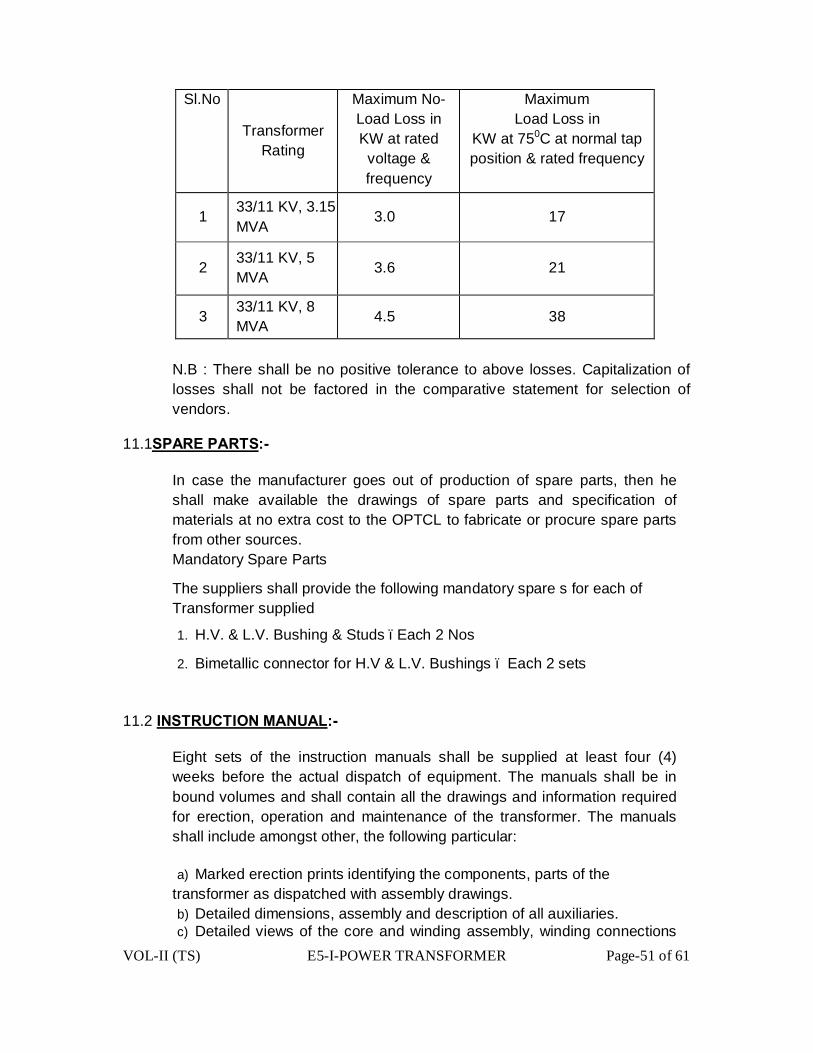
VOL-II (TS) E5-I-POWER TRANSFORMER Page-51 of 61
Sl.No
Transformer Rating
Maximum No- Load Loss in KW at rated voltage & frequency
Maximum Load Loss in
KW at 750C at normal tap position & rated frequency
1 33/11 KV, 3.15 MVA
3.0 17
2 33/11 KV, 5 MVA 3.6 21
3 33/11 KV, 8 MVA 4.5 38
N.B : There shall be no positive tolerance to above losses. Capitalization of losses shall not be factored in the comparative statement for selection of vendors.
11.1SPARE PARTS:-
In case the manufacturer goes out of production of spare parts, then he shall make available the drawings of spare parts and specification of materials at no extra cost to the OPTCL to fabricate or procure spare parts from other sources. Mandatory Spare Parts
The suppliers shall provide the following mandatory spare s for each of Transformer supplied
1. H.V. & L.V. Bushing & Studs –Each 2 Nos
2. Bimetallic connector for H.V & L.V. Bushings – Each 2 sets
11.2 INSTRUCTION MANUAL:-
Eight sets of the instruction manuals shall be supplied at least four (4) weeks before the actual dispatch of equipment. The manuals shall be in bound volumes and shall contain all the drawings and information required for erection, operation and maintenance of the transformer. The manuals shall include amongst other, the following particular:
a) Marked erection prints identifying the components, parts of the transformer as dispatched with assembly drawings. b) Detailed dimensions, assembly and description of all auxiliaries. c) Detailed views of the core and winding assembly, winding connections

VOL-II (TS) E5-I-POWER TRANSFORMER Page-52 of 61
and tapings tap changer construction etc. These drawings are required for carrying out overhauling operation at site.
d) Salient technical particulars of the transformer.
e) Copies of all final approved drawings.
f) Detailed O&M instructions with periodical check lists and Performa etc.
11.3 COMPLETENESS OF EQUIPMENT:-
All fittings and accessories, which may not be specifically mentioned in the specification but which are necessary for the satisfactory operation of the transformer, shall be deemed to be included in the specification and shall be furnished by the supplier without any extra charge. The equipment shall be complete in all details whether such details are mentioned in the specification or not, without any financial liability to the OPTCL under any circumstances.
11.4 TOOLS AND TACKLES:-
All the necessary tools and tackles required for normal operation & maintenance of the transformers shall be supplied by the Contractor.
12.0-COMMISSIONING:-
The equipments shall be commissioned as per CBIP manual, IS: 10028 and manufacturer’s recommendations. All the related drawings and manuals shall be pre-requisite for release of final payment.

VOL-II (TS) E5-I-POWER TRANSFORMER Page-53 of 61
ANNEXURE – I
(Technical Data Schedule for 3.15MVA, 5MVA & 8 MVA,33/11kV Power Transformers)
Sl. No. Description Bidder's offer
1. Name and address of the Manufacturer a) Transformer b) HV & LV Bushings c) Bimetallic connectors d) Transformer Oil e) On load tap changer f) Instruments g) Neutral Bushing CTs
2. Service ( Indoor / Outdoor ) 3. Normal continuous rating in KVA under site conditions at all taps :
a) HV winding (KVA) b) LV winding (KVA)
4. Rated Voltage a) HV winding (KV ) b) LV winding (KV)
5. Rated frequency (Hz) 6. No. of phases 7. Type of transformer 8. Connections
a) HV winding b) LV winding
9. Connections symbols HV – LV 10. Tappings
a) Range b) Number of steps c) Position of tapping on HT winding for high voltage variation
11. Reference ambient temperatures a) Maximum ambient air temperature (0C) b) Maximum daily average ambient temperature (0C) c) Minimum ambient air temperature (0C) d) Maximum yearly weighted average ambient temperature (0C)
12. Maximum temperature rise over ambient temperature a) Top oil by thermometer (0C) b) HV & LV windings by resistance measurement (0C)
Sl. Description Bidder's offer

VOL-II (TS) E5-I-POWER TRANSFORMER Page-54 of 61
No. c) Hot Spot Temperature rise of windings(º C) d) Limit for hot spot temperature for which the transformer is designed (º C)
e) Temperature gradient between windings and oil (0C)
f) Type of maximum winding temperature indicator (0C)
13. Voltage to earth for which the star point will be insulated
14. Cooling type 15. Losses
a) No-Load loss at rated voltage & rated frequency (KW)
b) Load loss at rated current at Normal Tap at 750 C (KW ) 16. Max. Current density in winding at rated current for normal tap position
a) HV winding (Amps/ sq.mm.) b) LV winding (Amps / sq.mm.)
17. Impedance voltage at rated current ,rated frequency and at 750 C expressed as percentage of rated voltage at :-
a) Principal (normal) tap (%) b) Highest tap (%) c) Lowest tap (%)
18. Reactance at rated current & frequency as percentage of rated voltage at: a) Principal (normal) tap b) Highest Tap c) Lowest Tap
19. Resistance at 75º C a) H.V. winding at normal tap position b) L.V. winding c) Resistance voltage drop at 75º C winding temperature expressed as percent
of rated voltage (%)
i) Principal/ normal tap ii) Highest tap iii) Lowest tap
20. Insulation level a) Separate source power frequency voltage withstand
i) HV winding (KV rms) ii) LV winding (KV rms)
b) Induced over voltage withstand i) HV winding (KV rms) ii) LV winding (KV rms)
c) Full wave lightning impulse withstand voltage Sl. No. Description Bidder's offer
i) HV winding (KV peak)
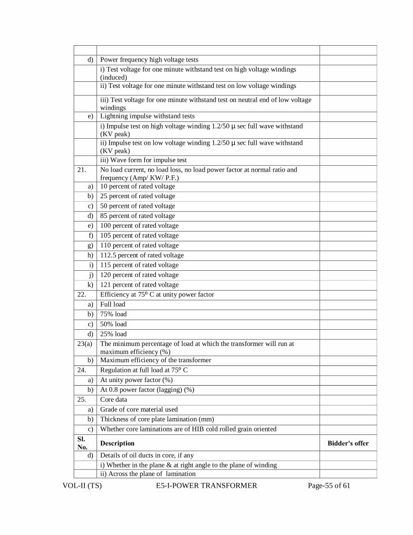
VOL-II (TS) E5-I-POWER TRANSFORMER Page-55 of 61
d) Power frequency high voltage tests
i) Test voltage for one minute withstand test on high voltage windings (induced)
ii) Test voltage for one minute withstand test on low voltage windings
iii) Test voltage for one minute withstand test on neutral end of low voltage windings
e) Lightning impulse withstand tests i) Impulse test on high voltage winding 1.2/50 µ sec full wave withstand
(KV peak)
ii) Impulse test on low voltage winding 1.2/50 µ sec full wave withstand (KV peak)
iii) Wave form for impulse test 21. No load current, no load loss, no load power factor at normal ratio and
frequency (Amp/ KW/ P.F.) a) 10 percent of rated voltage b) 25 percent of rated voltage c) 50 percent of rated voltage d) 85 percent of rated voltage e) 100 percent of rated voltage f) 105 percent of rated voltage g) 110 percent of rated voltage h) 112.5 percent of rated voltage i) 115 percent of rated voltage j) 120 percent of rated voltage k) 121 percent of rated voltage
22. Efficiency at 75º C at unity power factor a) Full load b) 75% load c) 50% load d) 25% load
23(a) The minimum percentage of load at which the transformer will run at maximum efficiency (%)
b) Maximum efficiency of the transformer 24. Regulation at full load at 75º C
a) At unity power factor (%) b) At 0.8 power factor (lagging) (%)
25. Core data a) Grade of core material used b) Thickness of core plate lamination (mm) c) Whether core laminations are of HIB cold rolled grain oriented
Sl. No. Description Bidder's offer
d) Details of oil ducts in core, if any i) Whether in the plane & at right angle to the plane of winding ii) Across the plane of lamination

VOL-II (TS) E5-I-POWER TRANSFORMER Page-56 of 61
e) i) Insulation of core lamination ii) Insulation of core plates iii) Type of core joints(Mitred or Mitred Step-lap) 26. Flux density
a) Designed maximum flux density at rated voltage and rated frequency (Tesla) b) Designed maximum operating flux density which the transformer can
withstand for one minute at normal tap (Tesla)
c) Designed maximum operating flux density which the transformer can withstand for five seconds at normal tap (Tesla)
27. Inter-Tap insulation a) Extent of extreme end turns reinforcement b) Extent of end turns reinforcement c) Extent of turn adjacent to tapping reinforced d) Test voltage for 10 seconds 50Hz inter-turn insulation test on (a) e) Test voltage for 10 seconds 50Hz inter-turn insulation test on (b)
f) Test voltage for 10 seconds 50Hz inter-turn insulation test on (c) 28. Windings:
a) Material b) Type of windings:
i) HV windings ii) LV windings
c) Insulation of HV windings d) Insulation of LV windings e) Insulation between HV & LV windings
29. Continuous rating under following conditions: a) At 40ºC ambient air temp. at site b) At 30ºC ambient air temp. at site c) At 20ºC ambient air temp. at site
30. Transformer Tank a) Material b) Thickness
- Top - Sides - Bottom
c) Details of painting - Inner surface
- Outer surface 31. Dimensions of 3 phase transformers: Sl. No. Description Bidder's offer
a) Max. Height to top of bushings (mm) b) Over-all length (mm) c) Over-all breadth (mm)
32. Weight data of transformer components : (Tolerance + 5% ) (approximate values not allowed )

VOL-II (TS) E5-I-POWER TRANSFORMER Page-57 of 61
a) Core excluding clamping (Kg) b) Core with clamping (Kg) c) HV winding insulated conductor (Kg) d) LV winding Insulated conductor (Kg) e) Coils with insulation (Kg.) f) Core and windings (Kg) g) Weight of steel (Kg) h) Fittings and accessories (Kg) i) Oil required for first filling including 10% extra (ltrs / Kg )
1. Oil in main tank ( Ltrs) 2. Oil in the conservator (Ltrs)
3. Oil in the radiators ( Ltrs ) 4. Oil in the OLTC (Ltrs.)
5. Overall total quantity of oil with 10% extra oil for first filling (ltrs / Kg) j) 1. Transportation weight excluding accessories (Kg)
2. Shipping details i) Weight of heaviest package (Kg.) ii) Dimension of largest package (Kg)
k) Untanking weight (Kg) l) Total weight of transformer with oil and fittings (Kg)
33. Bushing data : a) Type of bushing insulator
i) HV ii) LV iii) Neutral
b) Material of bushing (inner part / outer part) c) Weight of bushing insulator (Kg.) d) Quantity of oil in one bushing (lt.) e) Minimum dry withstand & flash over power frequency voltage of bushing
(KV)
f) Minimum wet withstand & flash over power frequency voltage of bushing (KV)
g) Minimum withstand & flashover impulse level (KV) h) Voltage rating (KV) i) Current rating (Amps.) j) Thermal Short Time current & Duration
Sl. No. Description Bidder's offer
k) Rated Dynamic current & its duration l) Cantilever with stand loading
m) Clearance in oil - phase to phase (mm) - phase to earth (mm)
n) Creepage distance in oil & air (mm) o) Minimum level of immersing / medium (oil ) (mm)
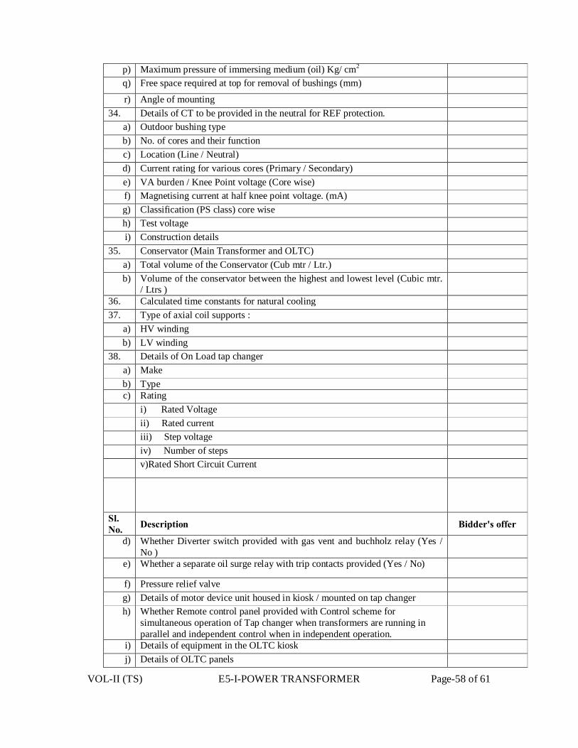
VOL-II (TS) E5-I-POWER TRANSFORMER Page-58 of 61
p) Maximum pressure of immersing medium (oil) Kg/ cm2 q) Free space required at top for removal of bushings (mm)
r) Angle of mounting 34. Details of CT to be provided in the neutral for REF protection.
a) Outdoor bushing type b) No. of cores and their function c) Location (Line / Neutral) d) Current rating for various cores (Primary / Secondary) e) VA burden / Knee Point voltage (Core wise) f) Magnetising current at half knee point voltage. (mA) g) Classification (PS class) core wise h) Test voltage i) Construction details
35. Conservator (Main Transformer and OLTC) a) Total volume of the Conservator (Cub mtr / Ltr.) b) Volume of the conservator between the highest and lowest level (Cubic mtr.
/ Ltrs )
36. Calculated time constants for natural cooling 37. Type of axial coil supports :
a) HV winding b) LV winding
38. Details of On Load tap changer a) Make b) Type c) Rating
i) Rated Voltage ii) Rated current iii) Step voltage iv) Number of steps v)Rated Short Circuit Current
Sl. No. Description Bidder's offer
d) Whether Diverter switch provided with gas vent and buchholz relay (Yes / No )
e) Whether a separate oil surge relay with trip contacts provided (Yes / No)
f) Pressure relief valve g) Details of motor device unit housed in kiosk / mounted on tap changer h) Whether Remote control panel provided with Control scheme for
simultaneous operation of Tap changer when transformers are running in parallel and independent control when in independent operation.
i) Details of equipment in the OLTC kiosk j) Details of OLTC panels

VOL-II (TS) E5-I-POWER TRANSFORMER Page-59 of 61
i) automatic tap changer relay ii) literature of all the relays iii) dimensions of OLTC, Panel L x B x H iv) thickness of sheet v) degree of protection vi) details of equipment supplied
39. Dispatch details : a) Approx. mass of heaviest Package (Kg) b) Approx. dimensions of largest Package
i) Length (mm) ii) Breadth (mm) iii) Height (mm)
40. Un-tanking height (mm) 41. Bimetallic connectors HV / LV
a) Normal current rating (A) b) Short time current rating (A) c) Tensile strength (Kg) d) Maximum temperature limit e) Dimensional sketch enclosed indicating tolerances (Yes/No) f) Minimum clearance (mm)
- Phase to phase - Phase to Earth
42. CORE ASSEMBLY :- a) Core diameter (mm ) b) Core window height (mm ) c) Core leg centre (mm ) d) Gross core cross – sectional area (m2)
e) Total height of core (mm ) f) Details of top end frame g) Details of Bottom end frame
Sl. No. Description Bidder's offer
h) Details of clamp plate (material, thickness, insulation) i) Total core weight (Kg ) j) Core loss, basing on core loss graph at operating flux density (rated voltage
and rated frequency ) ( KW )
k) Core stacking factor l) Net core area (Sq.m)
m) Margin towards corner joints, cross-fluxing, dielectric loss (KW) n) Total core loss at rated voltage and rated frequency (KW )
o) Describe location / method of core grounding p) Details of core- belting
i) Material , grade and type ii) Width
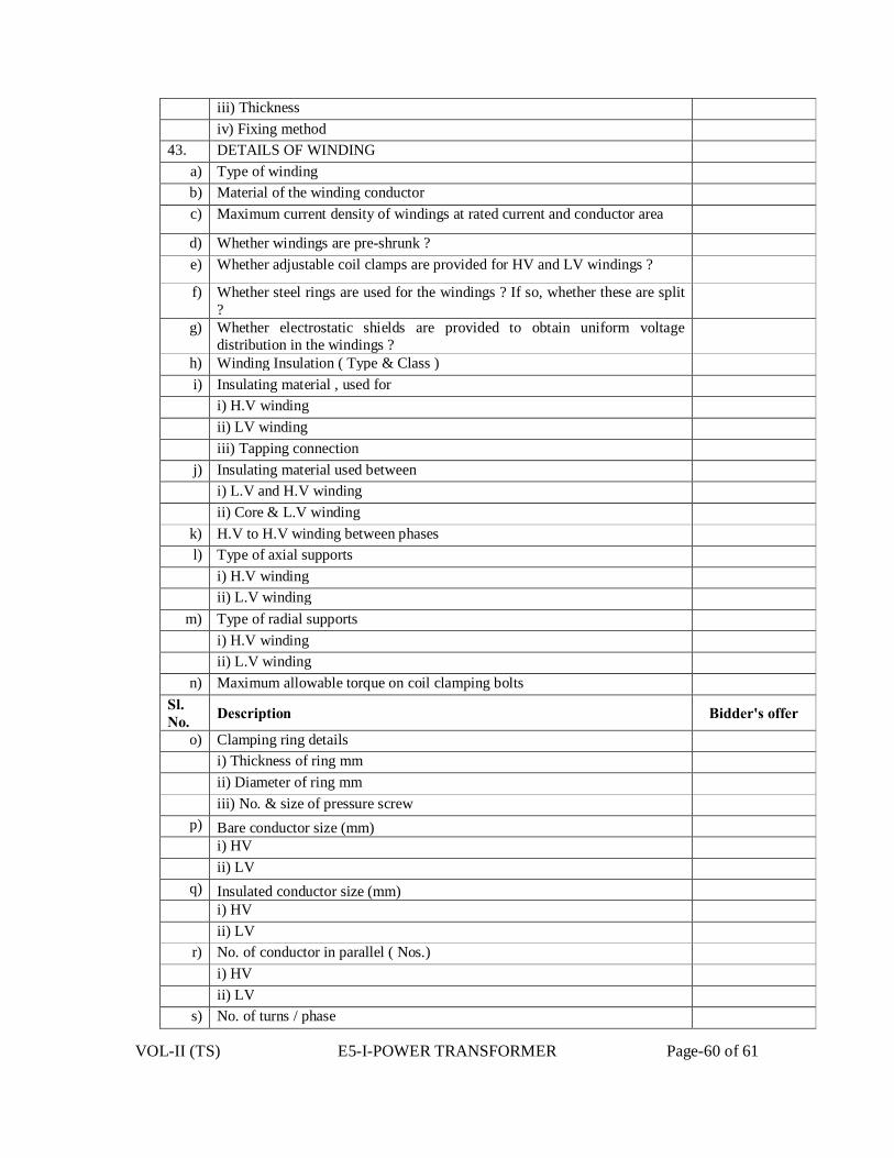
VOL-II (TS) E5-I-POWER TRANSFORMER Page-60 of 61
iii) Thickness iv) Fixing method
43. DETAILS OF WINDING a) Type of winding b) Material of the winding conductor c) Maximum current density of windings at rated current and conductor area
d) Whether windings are pre-shrunk ? e) Whether adjustable coil clamps are provided for HV and LV windings ?
f) Whether steel rings are used for the windings ? If so, whether these are split ?
g) Whether electrostatic shields are provided to obtain uniform voltage distribution in the windings ?
h) Winding Insulation ( Type & Class ) i) Insulating material , used for
i) H.V winding ii) LV winding iii) Tapping connection
j) Insulating material used between i) L.V and H.V winding ii) Core & L.V winding
k) H.V to H.V winding between phases l) Type of axial supports
i) H.V winding ii) L.V winding
m) Type of radial supports i) H.V winding ii) L.V winding
n) Maximum allowable torque on coil clamping bolts Sl. No. Description Bidder's offer
o) Clamping ring details i) Thickness of ring mm ii) Diameter of ring mm iii) No. & size of pressure screw
p) Bare conductor size (mm) i) HV ii) LV
q) Insulated conductor size (mm) i) HV ii) LV
r) No. of conductor in parallel ( Nos.) i) HV ii) LV
s) No. of turns / phase
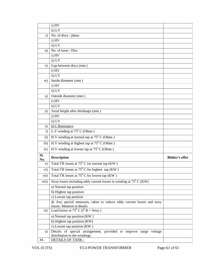
VOL-II (TS) E5-I-POWER TRANSFORMER Page-61 of 61
i) HV ii) LV
t) No. of discs / phase i) HV ii) LV
u) No. of turns / Disc i) HV ii) LV
v) Gap between discs (mm ) i) HV ii) LV
w) Inside diameter (mm ) i) HV
ii) LV x) Outside diameter (mm )
i) HV ii) LV
y) Axial height after shrinkage (mm ) i) HV ii) LV
z) D.C Resistance i) L.V winding at 750 C (Ohms )
ii) H.V winding at normal tap at 750 C (Ohms )
iii) H.V winding at highest tap at 750 C (Ohms )
iv) H.V winding at lowest tap at 750 C (Ohms )
Sl. No. Description Bidder's offer
v) Total I2R losses at 750 C for normal tap (KW )
vi) Total I2R losses at 750 C for highest tap (KW )
vii) Total I2R losses at 750 C for lowest tap (KW )
viii) Stray losses including eddy current losses in winding at 750 C (KW) a) Normal tap position b) Highest tap position c) Lowest tap position d) Any special measures, taken to reduce eddy current losses and stray
losses. Mention in details
ix) Load losses at 750 C (I2 R + Stray )
a) Normal tap position (KW ) b) Highest tap position (KW) c) Lowest tap position (KW )
x) Details of special arrangement, provided to improve surge voltage distribution in the windings.
44. DETAILS OF TANK :

VOL-II (TS) E5-I-POWER TRANSFORMER Page-62 of 61
a) Material of Transformer tank b) Type of tank c) Thickness of sheet (No approximate value to be mentioned)
i) Sides (mm) ii) Bottom (mm ) iii) Cover (mm ) iv ) Radiators (mm)
d) Inside dimensions of main tank (No approximation in dimensions to be used )
i) Length (mm) ii) Breadth (mm) iii) Height (mm )
e) Outside dimensions of main tank (No approximation in dimensions to be used )
i) Length (mm) ii) Breadth (mm) iii) Height (mm)
f) Vacuum recommended for hot oil circulation (torr / mm of Hg) g) Vacuum to be maintained during oil filling in transformer tank (torr / mm of
Hg)
h) Vacuum to which the tank can be subjected without distortion (torr / mm of Hg)
i) No. of bi-directional wheels provided j) Track gauge required for the wheels
i) Transverse axis Sl. No. Description Bidder's offer
ii) Longitudinal axis k) Type and make of pressure relief device and minimum pressure at which it
operates (Kpa )
45. CONSERVATOR :- a) Thickness of sheet (mm) b) Size (Dia x length ) (mm) c) Total volume (Litres) d) Volume between the highest and lowest visible oil levels (Litres)

VOL-II (TS) E5-I-POWER TRANSFORMER Page-63 of 61
VOL-II(TS) E5-IV- CURRENT TRANSFORMER (OUT DOOR) Page 1 of 15
TECHNICAL SPECIFICATION FOR
CURRENT TRANSFORMERS
33KV CT (OUT DOOR)
a) RATIO-400-200 /1-1-1A
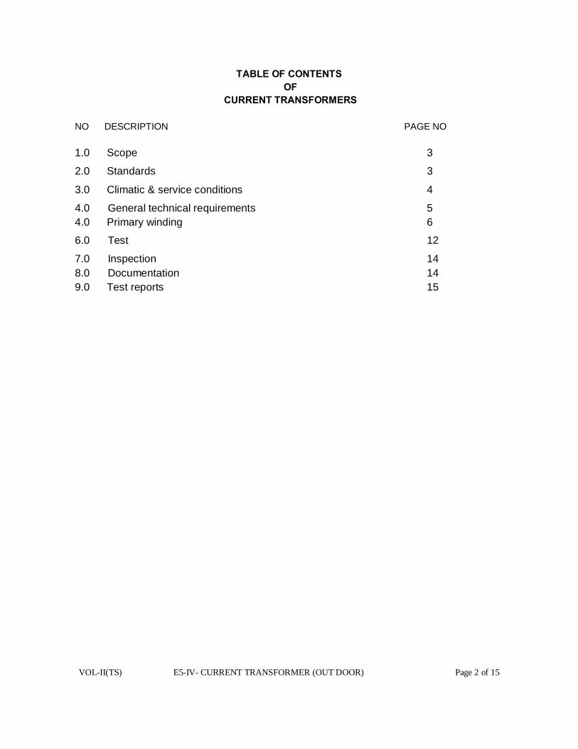
VOL-II(TS) E5-IV- CURRENT TRANSFORMER (OUT DOOR) Page 2 of 15
TABLE OF CONTENTS
OF CURRENT TRANSFORMERS
NO DESCRIPTION PAGE NO 1.0 Scope 3
2.0 Standards 3
3.0 Climatic & service conditions 4
4.0 General technical requirements 5 4.0 Primary winding 6
6.0 Test 12
7.0 Inspection 14 8.0 Documentation 14 9.0 Test reports 15

VOL-II(TS) E5-IV- CURRENT TRANSFORMER (OUT DOOR) Page 3 of 15
TECHNICAL SPECIFICATION FOR 33KV CURRENT TRANSFORMERS WITH METERING CORES OF ACCURACY CLASS 0.2
1.0 SCOPE :
1.1. The specification covers the design, manufacture, assembly, inspection and testing
at the manufacture’s work, packing and delivery F.O.R. (destination) of the outdoor
mounted dead tank type, single phase, single unit type current Transformers for protection
and metering services in 33KV solidly grounded system.
1.2. The current transformers shall be of the outdoor type, single phase, 50 C/S, oil
immersed, self cooled, hermetically sealed and suitable for operating in the tropical
conditions with maximum ambient temperature up to 500C. The C.TS should be suitable
for use in the areas subject to heavy lightning storms and highly polluted conditions.
1.3. Followings are the list of documents constituting this specification. [i] Technical specification(TS) [ii] Technical Requirements & General Requirement E21
[iii] Calibration Status of testing equipments and
meters / Instruments
E21
[iv] Check-List towards Type Test Reports E21
Note : E21 to be filled up by the Bidder
1.4 The current transformer shall conform in all respects to high standards of
engineering, design, workmanship and latest revisions of relevant standards at the time of
offer and purchaser shall have the power to reject any work or material which in his
judgment is not in full accordance therewith.
1.5 Bidders are required to quote for 0.2 accuracy class of metering cores with the
following data / information etc.
[a] Guaranteed Technical particulars.
[b] Technical literatures, brochures and drawings as per this specification. [c] Type Test Reports.
[d] List of orders, executed and User’s certificates, failing submission of the
above particulars with the offer, the tender may not be considered for evaluation. 2.0 STANDARDS
2.1 Except to the extent modified in the specification, the C.TS shall conform to the
latest editions and amendments of the standards listed hereunder.
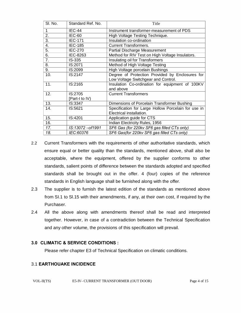
VOL-II(TS) E5-IV- CURRENT TRANSFORMER (OUT DOOR) Page 4 of 15
Sl. No. Standard Ref. No. Title
1 IEC-44 Instrument transformer-measurement of PDS 2. IEC-60 High Voltage Testing Technique. 3. IEC-171 Insulation co-ordination 4. IEC-185 Current Transformers. 5. IEC-270 Partial Discharge Measurement 6. IEC-8263 Method for RIV Test on High Voltage Insulators. 7. IS-335 Insulating oil for Transformers 8. IS:2071 Method of High Voltage Testing 9. IS:2099 High Voltage porcelain Bushings 10. IS:2147 Degree of Protection Provided by Enclosures for
Low Voltage Switchgear and Control. 11. IS:2165 Insulation Co-ordination for equipment of 100KV
and above 12. IS:2705
[Part-I to IV) Current Transformers
13. IS:3347 Dimensions of Porcelain Transformer Bushing 14. IS:5621 Specification for Large Hollow Porcelain for use in
Electrical installation. 15. IS:4201 Application guide for CTS 16. Indian Electricity Rules, 1956 17. IS:13072 –of1991 SF6 Gas (for 220kv SF6 gas filled CTs only) 18. IEC:60376 SF6 Gas(for 220kv SF6 gas filled CTs only)
2.2 Current Transformers with the requirements of other authoritative standards, which
ensure equal or better quality than the standards, mentioned above, shall also be
acceptable, where the equipment, offered by the supplier conforms to other
standards, salient points of difference between the standards adopted and specified
standards shall be brought out in the offer. 4 (four) copies of the reference
standards in English language shall be furnished along with the offer.
2.3 The supplier is to furnish the latest edition of the standards as mentioned above
from SI.1 to Sl.15 with their amendments, if any, at their own cost, if required by the
Purchaser.
2.4 All the above along with amendments thereof shall be read and interpreted
together. However, in case of a contradiction between the Technical Specification
and any other volume, the provisions of this specification will prevail.
3.0 CLIMATIC & SERVICE CONDITIONS :
Please refer chapter E3 of Technical Specification on climatic conditions.
3.1 EARTHOUAKE INCIDENCE

VOL-II(TS) E5-IV- CURRENT TRANSFORMER (OUT DOOR) Page 5 of 15
The current Transformers are to be designed to withstand earthquakes of an
intensity equivalent to seismic acceleration of 0.3g in the horizontal direction and
0.15g in the vertical direction, where ‘g’ stands for acceleration due to gravity.
3.2 The current Transformers covered under this specification shall be suitable for
outdoor installation.
4.0 GENERAL TECHNICAL REQUIREMENTS :
4.1 The C.T. shall be of dead tank design and shall be so constructed that it can be
easily transported to site within the allowable limitation and in horizontal position if the
transport limitations so demand. For compensation of variation in the oil volume due to
ambient variation, nitrogen cushion / metal bellows shall be used. Rubber diaphragms
shall not be permitted for this purpose.
4.2 The C.T. secondary terminals shall be brought out in a weather proof terminal box.
The terminal box shall be provided with removable gland plate and gland (s) suitable
for 1100 volts grade PVC insulated, PVC sheathed, multicore 4 Sq. mm stranded
copper conductor cable. The terminal blocks shall be stud-type and provided with
ferrules indelibly marked or numbered. The terminals shall be rated for not less than 10
Amps. The terminal box shall be dust and vermin proof. Suitable arrangements shall be
made for drying of air inside the secondary terminal box. The dimensions of the
terminal box and its openings shall be adequate to enable easy access and working
space with the use of normal tools.
4.3 Polarity shall be indelibly marked on each primary and secondary terminal. Facility
shall be provided for short-circuiting and grounding of the C.T. secondary terminals
inside the terminal box.
4.4 The C.T. shall be provided with non-corrosive, legible name plate with the
information, specified in the relevant standards, duly engraved/punched on it.
4.5 The current Transformer shall be vacuum filled with oil after processing and thereafter
hermetically sealed to eliminate breathing and to prevent air and moisture from entering
the tanks. Oil filling and / or sampling cocks, if provided to facilitate factory processing
should be properly sealed before despatching the C.T., The method adopted for
hermetic sealing shall be described in the offer.
4.6 The castings of base, collar etc. shall be die cast and tested before assembly to detect
cracks and voids, if any.
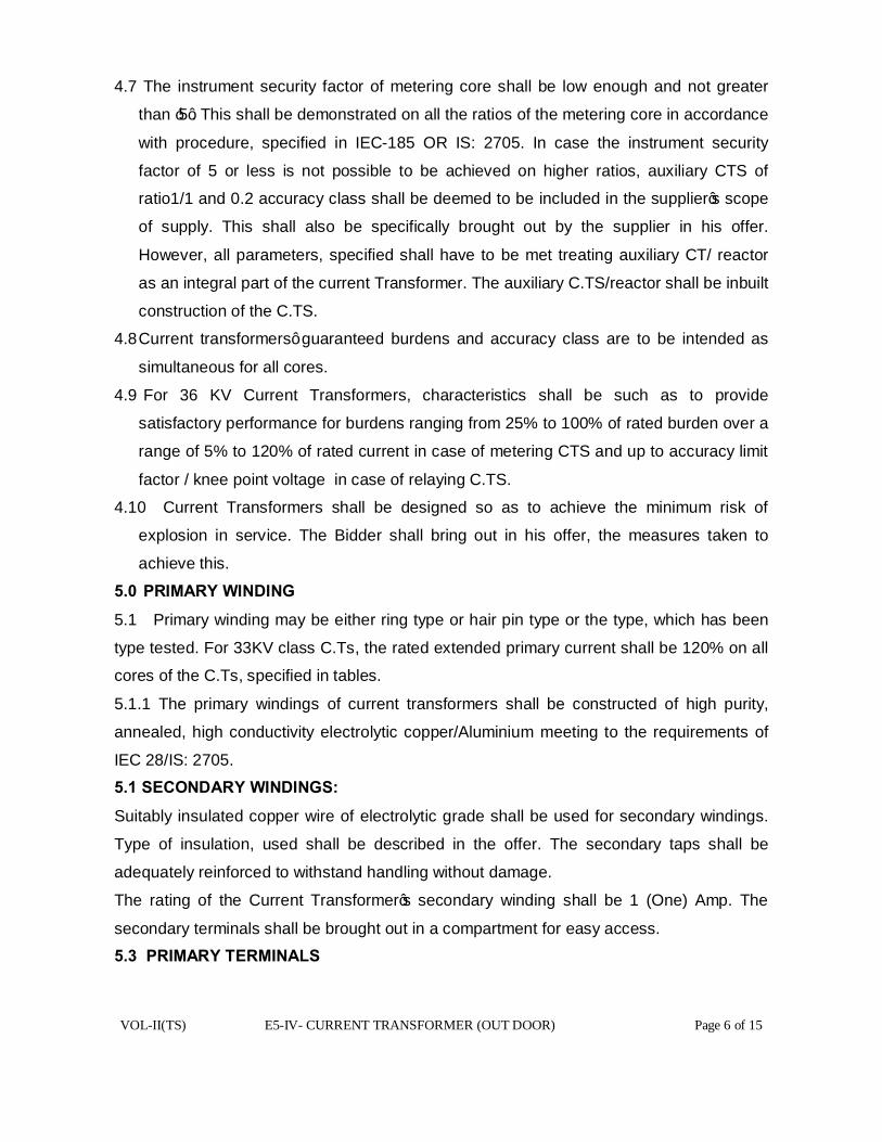
VOL-II(TS) E5-IV- CURRENT TRANSFORMER (OUT DOOR) Page 6 of 15
4.7 The instrument security factor of metering core shall be low enough and not greater
than ‘5’. This shall be demonstrated on all the ratios of the metering core in accordance
with procedure, specified in IEC-185 OR IS: 2705. In case the instrument security
factor of 5 or less is not possible to be achieved on higher ratios, auxiliary CTS of
ratio1/1 and 0.2 accuracy class shall be deemed to be included in the supplier’s scope
of supply. This shall also be specifically brought out by the supplier in his offer.
However, all parameters, specified shall have to be met treating auxiliary CT/ reactor
as an integral part of the current Transformer. The auxiliary C.TS/reactor shall be inbuilt
construction of the C.TS.
4.8 Current transformers’ guaranteed burdens and accuracy class are to be intended as
simultaneous for all cores.
4.9 For 36 KV Current Transformers, characteristics shall be such as to provide
satisfactory performance for burdens ranging from 25% to 100% of rated burden over a
range of 5% to 120% of rated current in case of metering CTS and up to accuracy limit
factor / knee point voltage in case of relaying C.TS.
4.10 Current Transformers shall be designed so as to achieve the minimum risk of
explosion in service. The Bidder shall bring out in his offer, the measures taken to
achieve this.
5.0 PRIMARY WINDING
5.1 Primary winding may be either ring type or hair pin type or the type, which has been
type tested. For 33KV class C.Ts, the rated extended primary current shall be 120% on all
cores of the C.Ts, specified in tables.
5.1.1 The primary windings of current transformers shall be constructed of high purity,
annealed, high conductivity electrolytic copper/Aluminium meeting to the requirements of
IEC 28/IS: 2705.
5.1 SECONDARY WINDINGS:
Suitably insulated copper wire of electrolytic grade shall be used for secondary windings.
Type of insulation, used shall be described in the offer. The secondary taps shall be
adequately reinforced to withstand handling without damage.
The rating of the Current Transformer’s secondary winding shall be 1 (One) Amp. The
secondary terminals shall be brought out in a compartment for easy access.
5.3 PRIMARY TERMINALS
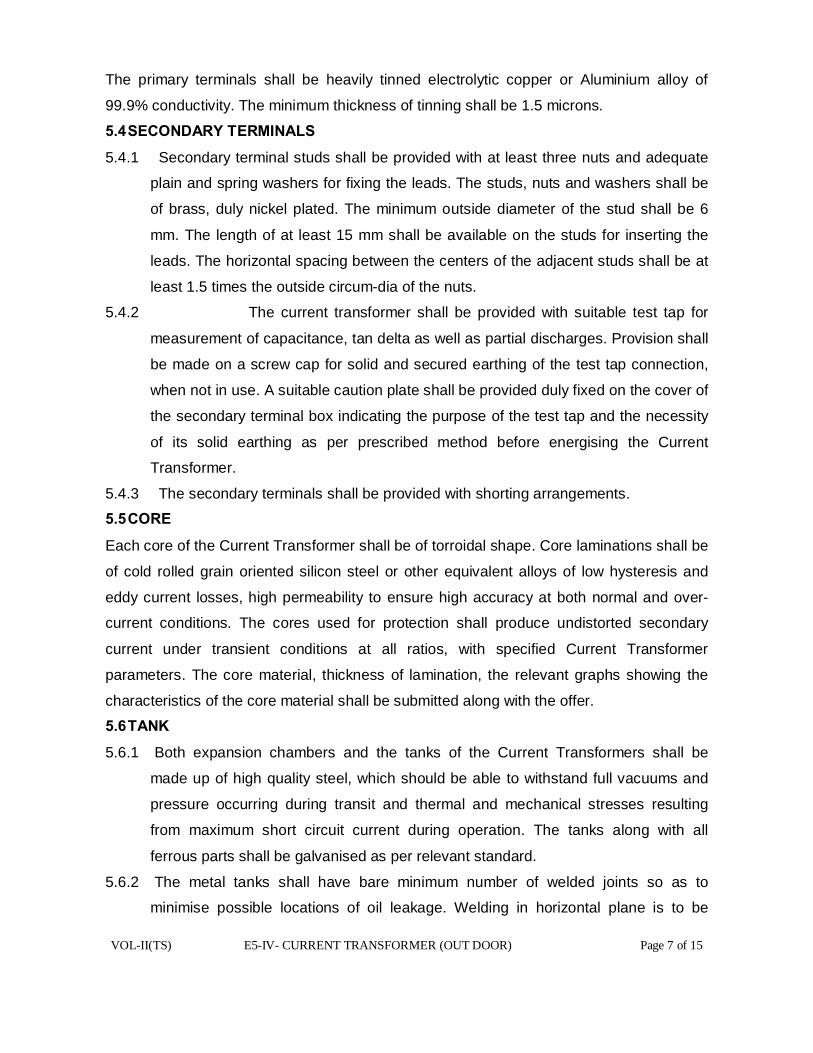
VOL-II(TS) E5-IV- CURRENT TRANSFORMER (OUT DOOR) Page 7 of 15
The primary terminals shall be heavily tinned electrolytic copper or Aluminium alloy of
99.9% conductivity. The minimum thickness of tinning shall be 1.5 microns.
5.4 SECONDARY TERMINALS
5.4.1 Secondary terminal studs shall be provided with at least three nuts and adequate
plain and spring washers for fixing the leads. The studs, nuts and washers shall be
of brass, duly nickel plated. The minimum outside diameter of the stud shall be 6
mm. The length of at least 15 mm shall be available on the studs for inserting the
leads. The horizontal spacing between the centers of the adjacent studs shall be at
least 1.5 times the outside circum-dia of the nuts.
5.4.2 The current transformer shall be provided with suitable test tap for
measurement of capacitance, tan delta as well as partial discharges. Provision shall
be made on a screw cap for solid and secured earthing of the test tap connection,
when not in use. A suitable caution plate shall be provided duly fixed on the cover of
the secondary terminal box indicating the purpose of the test tap and the necessity
of its solid earthing as per prescribed method before energising the Current
Transformer.
5.4.3 The secondary terminals shall be provided with shorting arrangements.
5.5 CORE
Each core of the Current Transformer shall be of torroidal shape. Core laminations shall be
of cold rolled grain oriented silicon steel or other equivalent alloys of low hysteresis and
eddy current losses, high permeability to ensure high accuracy at both normal and over-
current conditions. The cores used for protection shall produce undistorted secondary
current under transient conditions at all ratios, with specified Current Transformer
parameters. The core material, thickness of lamination, the relevant graphs showing the
characteristics of the core material shall be submitted along with the offer.
5.6 TANK
5.6.1 Both expansion chambers and the tanks of the Current Transformers shall be
made up of high quality steel, which should be able to withstand full vacuums and
pressure occurring during transit and thermal and mechanical stresses resulting
from maximum short circuit current during operation. The tanks along with all
ferrous parts shall be galvanised as per relevant standard.
5.6.2 The metal tanks shall have bare minimum number of welded joints so as to
minimise possible locations of oil leakage. Welding in horizontal plane is to be
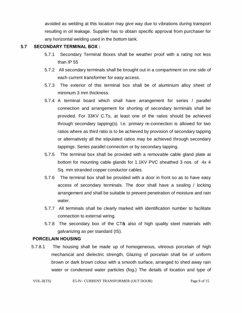
VOL-II(TS) E5-IV- CURRENT TRANSFORMER (OUT DOOR) Page 8 of 15
avoided as welding at this location may give way due to vibrations during transport
resulting in oil leakage. Supplier has to obtain specific approval from purchaser for
any horizontal welding used in the bottom tank.
5.7 SECONDARY TERMINAL BOX :
5.7.1 Secondary Terminal Boxes shall be weather proof with a rating not less
than IP 55
5.7.2 All secondary terminals shall be brought out in a compartment on one side of
each current transformer for easy access.
5.7.3 The exterior of this terminal box shall be of aluminium alloy sheet of
minimum 3 mm thickness.
5.7.4 A terminal board which shall have arrangement for series / parallel
connection and arrangement for shorting of secondary terminals shall be
provided. For 33KV C.Ts, at least one of the ratios should be achieved
through secondary tapping(s). I.e. primary re-connection is allowed for two
ratios where as third ratio is to be achieved by provision of secondary tapping
or alternatively all the stipulated ratios may be achieved through secondary
tappings. Series parallel connection or by secondary tapping.
5.7.5 The terminal box shall be provided with a removable cable gland plate at
bottom for mounting cable glands for 1.1KV PVC sheathed 3 nos. of 4x 4
Sq. mm stranded copper conductor cables.
5.7.6 The terminal box shall be provided with a door in front so as to have easy
access of secondary terminals. The door shall have a sealing / locking
arrangement and shall be suitable to prevent penetration of moisture and rain
water.
5.7.7 All terminals shall be clearly marked with identification number to facilitate
connection to external wiring.
5.7.8 The secondary box of the CT’s also of high quality steel materials with
galvanizing as per standard (IS).
PORCELAIN HOUSING
5.7.8.1 The housing shall be made up of homogeneous, vitreous porcelain of high
mechanical and dielectric strength, Glazing of porcelain shall be of uniform
brown or dark brown colour with a smooth surface, arranged to shed away rain
water or condensed water particles (fog.) The details of location and type of
VOL-II(TS) E5-IV- CURRENT TRANSFORMER (OUT DOOR) Page 9 of 15
joint, if provided on the porcelain, shall be furnished by the Bidder along with the
offer.
5.7.8.2 The bushings of the Current Transformers shall conform to the latest edition of
IS: 2099. The hollow porcelain insulator shall conform to the latest edition of IS:
5621.
5.7.8.3 The insulators shall be cemented with Portland cement to the flanges resulting
in high mechanical, tensile and breaking strength.
5.7.8.4 The bushings shall have ample insulation, mechanical strength and rigidity for
the condition under which they shall be used and shall be designed to prevent
accumulation of explosive gases and provide adequate oil circulation to remove
the internal heat.
5.7.8.5 Cast metal end caps for the bushings shall be of high strength, hot dip
glavanised malleable iron. They shall have smooth surface to prevent discharge
taking place between the metal parts and porcelain as a result of ionisation.
5.7.8.6 The insulation of bushings shall be coordinated with that of the current
transformer such that the flashover, if any, will occur only external to the Current
Transformer.
5.7.8.7 Oil level gauge and convenient means of filling, sampling and draining of oil
should be provided.
5.7.9 End shields should be provided for distribution of stresses.
5.7.10 Corona shields for bushings, if required should be provided.
5.8 INSULATING MEDIUM ( OIL TYPE)
The quantity of insulating oil for the filling and the complete specification of the insulating
oil shall be stated. The oil shall comply in all respects with the provisions of latest edition
of IS: 335. The current Transformers shall be supplied, filled with purified oil completely.
5.8.1 PREVENTION OF OILLEAKAGE AND ENTRY OF MOISTURE:
The supplier shall ensure that the sealing of the Current Transformer is properly achieved.
In this connection, the arrangement provided by the supplier at various locations including
the following ones shall be described, supported by sectional drawings.
(a) locations of emergence of primary and secondary terminals.
(b) Interface between porcelain housing and metal tank/s
(c) Cover of the secondary terminal box.
VOL-II(TS) E5-IV- CURRENT TRANSFORMER (OUT DOOR) Page 10 of 15
5.8.2 Nuts and bolts or screws, used for fixation of the interfacing porcelain bushings for taking
out terminals shall be provided on flanges, cemented to the bushings and not on the
porcelain.
5.8.3 For gasketed joints, wherever used, nitrite butyl rubber gaskets shall be used. The
gasket shall be fitted in properly machined groove with adequate space for
accommodating the gasket under compression.
5.9 FITTINGS AND ACCESSORIES :
Fittings and accessories, listed below shall be supplied with each Current Transformer.
Any fitting, required essential other than those listed below shall also be supplied along
with each Current Transformer without any extra cost to the purchaser:
(a) Oil level gauge.
(b) Oil filling hole and cap.
(c) Pressure relieving device.
(d) Phase terminal connectors.
(e) Lifting lugs for core and windings, bushings and complete Current Transformers.
(f) Tank earthing pads/terminals with necessary nuts, bolts and washers for connecting
to purchaser’s earth strip.
(g) Name / Rating plate.
5.9.1 (A) OIL LEVEL GAUGE :
An oil level gauge shall be provided to indicate the oil level in the Current
Transformer. This gauge shall be mounted in such a way that the oil level can be
seen from ground level. If metal bellow is used, a ground glass window shall be
provided to monitor the position of the metal bellow. The metal below shall be tested
in accordance with relevant standards. The details shall be to the approval of the
purchaser.
5.9.2 PRESSURE RELIEVING DEVICE :
Each Current Transformer shall be provided with a pressure relieving device so as
to protect bushing of the Current Transformer even under unfavorable
conditions. In case of non provision of the PRD, the same should be brought out
clearly in the offer with detailed explanation and proof.
5.9.3 (A) OIL DRAIN COCK :

VOL-II(TS) E5-IV- CURRENT TRANSFORMER (OUT DOOR) Page 11 of 15
An oil drain cock along with a stop cock shall be provided in the bottom flange so as
to permit taking of oil samples for testing, if required.
5.9.4 EARTHING :
Metal tank of each Current Transformer shall be provided with two separate
earthing terminals for bolted connection to 50mm X 6 mm flat, to be provided by the
purchaser for connection to station earth-mat.
5.9.5 LIFTING ARRANGMENT :
The Current Transformer shall be provided with suitable lifting arrangement to lift
the entire unit. The lifting arrangement shall be clearly shown in the general
arrangement drawing. Lifting arrangement (lifting eye) shall be positioned in such a
way so as to avoid any damage to the porcelain housing or the tanks during lifting
for installation / transport. Necessary string guides shall be offered which shall be of
removable type.
5.9.6 NAME PLATE & MARKING :
5.9.6.1 The Current Transformer shall be provided with non-corrosive, legible name
plate with the information specified in relevant standards, duly
engraved/punched on it.
5.9.6.2 A schematic drawing indicating the connections shall be provided in the interior
of the Terminal box.
5.9.7 TERMINAL CONNECTORS :
All the Current Transformers shall be provided with bimetallic solder less clamp
type, rigid type terminal connectors, suitable for
(i) 33KV C.T. – AAAC 150 Sq mm conductor.
Each terminal connector shall be of universal type, suitable for both horizontal and vertical
connections to the transmission line conductors / station bus bars.
5.9.7.1 Terminal connectors shall be manufactured and tested as per IS: 5561.
5.9.7.2 All castings shall be free from blow holes, surface blisters, cracks and cavities.
All sharp edges and corners shall be blurred and rounded off. 5.9.7.3 No part of a clamp shall be less than 10mm thick.
5.9.7.4 All ferrous parts shall be hot-dip galvanised conforming to relevant standard.
5.9.7.5 For bimetallic connectors, copper alloy linear of minimum thickness of 2 mm
shall be cast integral with aluminium body.
VOL-II(TS) E5-IV- CURRENT TRANSFORMER (OUT DOOR) Page 12 of 15
5.9.7.6 All current carrying parts shall be designed and manufactured to have minimum
contact resistance.
5.9.7.7 Connectors shall be designed to be corona free in accordance with the
requirements, stipulated in IS: 5561. 6.0 TEST:
6.1 TYPE TESTS & SPECIAL TESTS:-
The current transformers, offered should have been subjected to the following type
tests and Special Tests in Government approved test laboratory. The bidder shall
furnish four sets of type test and Special Tests reports along with the offer for 0.2
accuracy class CTs. These tests should not have been conducted earlier than five
years from the date of opening of the bid. For any change in the design/type already
type tested and the design/type offered against this specification, the purchaser
reserves the right to demand repetition of some or all type & special tests without
any extra cost to OPTCL in the presence of OPTCL’s representative(s) at the cost
of the supplier.
(a) Lightning Impulse Voltage Test.
(b) High Voltage power frequency wet withstands voltage Test.
(c) Short time current test.
(d) Temperature rise test.
(e) Determination of errors or other characteristics according to the requirements of the
appropriate designation and accuracy class as per individual parts of IS: 2705.
(f) Instrument Security Factor Test.
(g) IP-55 Test on Secondary Terminal Box.
N.B:
• Lightning Impulse Test, switching Impulse Voltage test and High Voltage power
frequency wet withstand voltage Tests should have been carried out on the same current
transformer.
• After the current transformers have been subjected to lightning Impulse Test, and
High Voltage power frequency wet withstand voltage tests, these must have been
subjected to all the routine tests as per IS:2705 (Part-I to IV).
6.2 ROUTINE TESTS :
VOL-II(TS) E5-IV- CURRENT TRANSFORMER (OUT DOOR) Page 13 of 15
The following routine tests shall be conducted on each Current Transformer in the
presence of OPTCL’s representative(s) for which no charges will be payable by OPTCL.
No sampling will be allowed.
(i) Appearance and Dimensional Check.
(ii) Verification of Terminal Marking and polarity.
(iii) Verification of all individual parts / components of the Current Transformer so as to
ensure to have complied the above specification.
(iv) Measurement of Insulation Resistance.
(v) Power Frequency Dry withstanding Test on Primary and Secondary winding
including primary intersections.
(vi) Over – Voltage Interturn test.
(vii) Partial discharge Test
(viii) Knee point voltage and Excitation current measurement for ‘PS’ class cores.
(ix) Secondary winding resistance measurement.
(x) Determination of errors.
(xi) ISF Test.
(xii) Leakage Test.
(xiii) Magnetization Characteristics of the Current Transformers.
(xiv) Turn ratio error on ‘PS’ class cores.
(xv) Measurement of capacitance
(xvi) Measurement of tan delta at 0.3, 0.7, 1.0 and 1.lUм/√3 for 33KV C.Ts.
• The Method For Conducting Partial Discharge Test.
The test circuit for the measurement of partial discharge (PD) should have been in
accordance with sub-clause 4.2 of IEC-270. The applied voltage should be raised to
the rated voltage of the Current Transformers and should have been maintained for a
period greater than or equal to 10 seconds. The voltage should have been reduced to
measuring voltage as specified in the IS and maintained for a period greater than or
equal to 1 minute. The PD should not exceed 10 Pico-coulombs.
7.0 INSPECTION :
7.1 The purchaser shall have access at all times to the works and all other places of
manufacture, where the Current Transformers are being manufactured and the supplier
shall provide all facilities for unrestricted inspection of the supplier’s works, raw materials,
manufacture of all the accessories and for conducting the necessary tests.

VOL-II(TS) E5-IV- CURRENT TRANSFORMER (OUT DOOR) Page 14 of 15
7.2 The supplier shall keep the purchaser informed in advance of the time of starting
and of the progress of manufacture of equipment in its various stages so that arrangement
could be made for inspection.
7.3 No material shall be despatched from its point of manufacture unless the material
has been satisfactorily inspected, tested and despatch clearance
issued. However, the purchaser reserves the right to alter the despatch schedule, attached
to this specification without any extra financial liability to OPTCL.
7.3.1 The acceptance of any quantity of equipment shall in no way relieve the supplier of
his responsibility for meeting all the requirements of this specification and shall not prevent
subsequent rejection, if such equipments are found to be defective.
8.0 DOCUMENTATION :
8.1 All drawings shall conform to relevant Indian Standard as per relevant IS. All drawings
shall be in ink and suitable for microfilming. All dimensions and data shall be in S.I. units.
8.2 The supplier shall furnish four sets of following drawings/documents along with his
offer for 0.2 accuracy class metering core CTs.
(a) General outline and assembly drawings of the Current Transformers.
(b) Sectional views showing.
(i) General constructional features.
(ii) Materials / gaskets / sealing used.
(iii) The insulation of the winding arrangement, method of connection of the primary /
secondary winding to the primary / secondary terminals etc.
(c) Schematic drawing
(d) Rating and Diagram plate.
(e) Secondary Terminal Box.
(f) Assembly Sectional view of Primary Terminal
(g) Assembly drawing for secondary terminal.
(h) The detailed dimensional drawing of Porcelain Housing such as ID, OD, thickness
and Insulator details such as height, profile of petticoats, angle of inclination and gap
between successive petticoats, total creepage distance etc.
(i) Sectional view of Pressure Release device.
(j) Drawing showing details of Oil level Indicator.
VOL-II(TS) E5-IV- CURRENT TRANSFORMER (OUT DOOR) Page 15 of 15
(k) All type and special test reports relating to tests, as mentioned at CI. No. 6.1 of this
Technical Specification.
(l) Ratio and phase angle error curves for CTS.
(m) Magnetization characteristic curves such as B-H curves and sp.loss vs. flux density
curves.
(n) Drawings for Terminal Connector. (o)
9.0 TEST REPORTS :
(i) A set of type test and special test reports if any shall be furnished to the purchaser
during detailed Engineering & drawing approval.
(ii) Copies of acceptance test reports and routine test reports shall be furnished to the
purchaser. One copy will be returned, duly certified by the purchaser and only thereafter
shall the materials be despatched.
(iii) All records of routine test reports shall be maintained by the supplier at his works for
periodic inspection by the purchaser.
(iv) All test reports of tests, conducted during manufacture shall be maintained
by the supplier. These shall be produced for verification as and when required by
the purchaser.
VOL-II(TS) E5-IX- SUB-STATION STRUCTURE Page-1 of 6
TECHNICAL SPECIFICATION FOR
SUB STATION STRUCTURE

VOL-II(TS) E5-IX- SUB-STATION STRUCTURE Page-2 of 6
TABLE OF CONTENTS OF
SUB STATION STRUCTURES
NO DESCRIPTION PAGE NO.
1.0 Scope 3
2.0 Standards 3
3.0 Column Structure 3
4.0 Beams/Gliders 3
5.0 Dimensions and Properties 3
6.0 Tests 4
7.0 Bolts & Nuts 5
8.0 Galvanising 6
9.0 Levels & Plates 6
Sub station Structures

VOL-II(TS) E5-IX- SUB-STATION STRUCTURE Page-3 of 6
1.0 Scope : All the galvanized Substation Structures shall be provided by the Contractor. 2.0 Standards : The steel materials shall comply with the requirements of latest issue of I.S
:808 & I.S: 2062 for Gr – A except where specified otherwise. 3.0 Column Structure
The T1, T2, type H Pole structures are to be constructed with two parallel run 7.5 Meter meter long 150 x 76 x 6.5 mm G.I. Channels. Both the channels are separated by 150 mm distance (run through the entire length). The channels are further connected with 22 No. stiffeners (11 on each side) of size 100 x 270 x 5.7mm G.I. Flats welded to both the channels along 75 mm side (separated by 150 mm).
At the bottom the column is fixed with a BASE Plate (i) 620 x 620 x 12 mm galvanized & 6 Nos. of 33.5 mm dia holes for taking foundation bolts of size 32 mm dia 1400 mm long. On both sides of the channels (300 mm side) two nos. of stiffeners (ii) are welded with base plate and on 150 mm side two stiffeners (iii) are welded with base plate.
4.0 Beams / Girders:
The girders / beams shall be fabricated from galvanized 125 x 65 x 5.3mm channels as per the drawings / field requirements.
5.0 Dimensions and Properties
MC DESIGNATION 150 x 76 mm MC 125 x 65 mm MC Weight kg/m “M” 17.7 13.1 Sectional Area (cm2) “a” 22.6 16.7 Depth of Section (mm) “D” 150 125 Width of Flange (mm) “B” 76 65 Thickness of Flange (mm) “t” 6.5 5.3 Thickness of Web (mm) ”T” 9.00 8.2
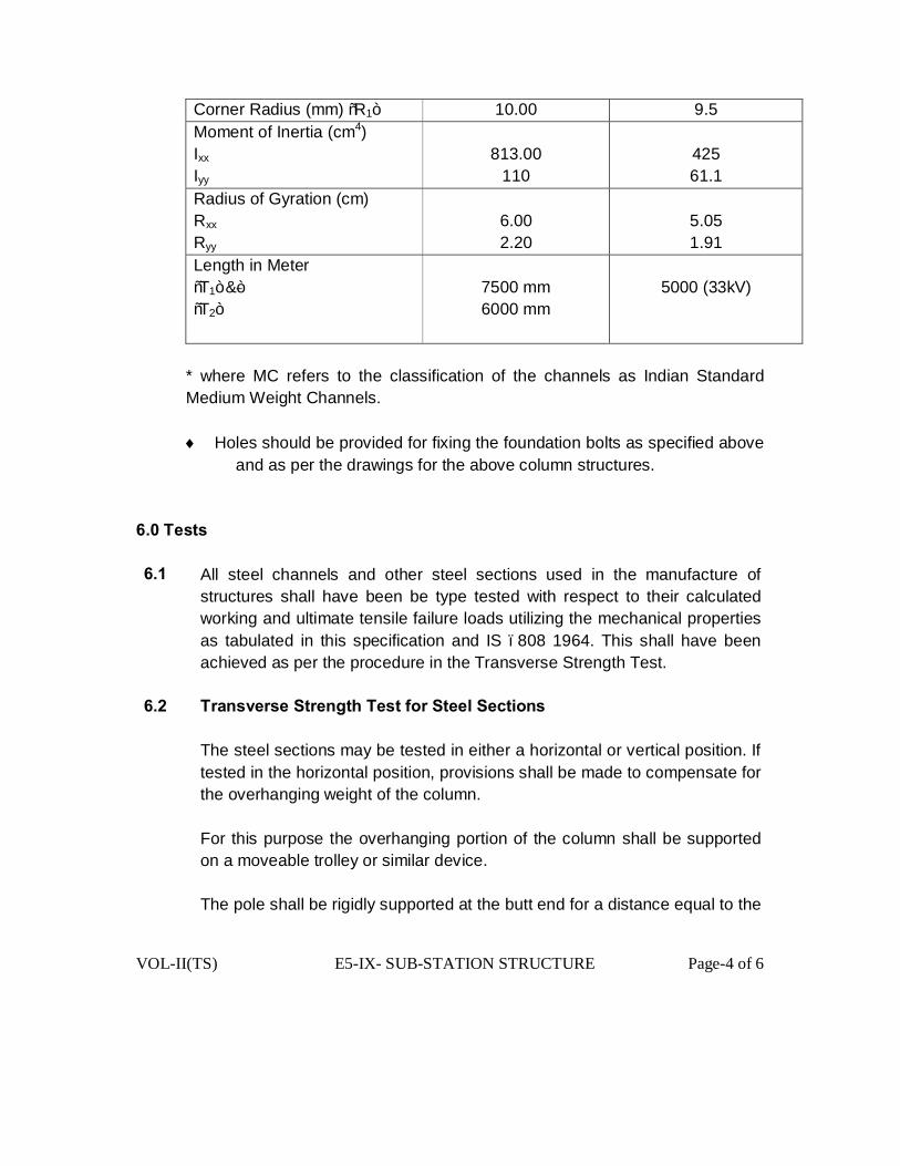
VOL-II(TS) E5-IX- SUB-STATION STRUCTURE Page-4 of 6
Corner Radius (mm) “R1” 10.00 9.5 Moment of Inertia (cm4) Ixx Iyy
813.00
110
425 61.1
Radius of Gyration (cm) Rxx Ryy
6.00 2.20
5.05 1.91
Length in Meter “T1” &” “T2”
7500 mm 6000 mm
5000 (33kV)
* where MC refers to the classification of the channels as Indian Standard Medium Weight Channels. ♦ Holes should be provided for fixing the foundation bolts as specified above
and as per the drawings for the above column structures. 6.0 Tests 6.1 All steel channels and other steel sections used in the manufacture of
structures shall have been be type tested with respect to their calculated working and ultimate tensile failure loads utilizing the mechanical properties as tabulated in this specification and IS –808 1964. This shall have been achieved as per the procedure in the Transverse Strength Test.
6.2 Transverse Strength Test for Steel Sections
The steel sections may be tested in either a horizontal or vertical position. If tested in the horizontal position, provisions shall be made to compensate for the overhanging weight of the column.
For this purpose the overhanging portion of the column shall be supported on a moveable trolley or similar device.
The pole shall be rigidly supported at the butt end for a distance equal to the
VOL-II(TS) E5-IX- SUB-STATION STRUCTURE Page-5 of 6
designed depth of planting.
The working load on the column should correspond to those that are likely to come onto the column during it’s working life. The offered designs shall meet system requirements with the point of application of the working loads as per the Bidder’s design but not more than 600 mm from the top of the column.
The steel column shall be deemed to have passed the test if no permanent deformation is visible at the rigidly supported end and the permanent set at the point of load application does not exceed 13 mm.
The load shall then be reduced to zero and increased gradually to a load equal to the design working load plus 10% of the minimum ultimate transverse load, and held for 2 minutes. The procedure shall be repeated until the load reaches a value of 80% of the minimum ultimate transverse load and thereafter increased in increments of 5% until failure occurs.
Each time the load is applied, it shall be held from two minutes. The column shall be deemed not to have passed the test if the observed
ultimate transverse load is less than the design ultimate transverse load.
The factor of safety (FOS) for steel section is 2.
7.0 Bolts and nuts
All bolts, studs, screw threads, bolt heads and nuts shall comply with the appropriate national standards for metric threads, or the technical equivalent.
All nuts and pins shall be adequately locked.
Head of the bolt in bolt and nut assembly in the horizontal plane must remain in the top. All bolts, nuts shall be treated to prevent corrosion, by hot dip galvanising and washers are to be electro galvanized.
Each bolt or stud shall project minimum three threads through its nut, except when otherwise approved for terminal board studs or relay stems.
VOL-II(TS) E5-IX- SUB-STATION STRUCTURE Page-6 of 6
8.0 Galvanising
8.1 General
All machining, drilling, welding, engraving, scribing or other manufacturing activities which would damage the final surface treatment shall be completed before the specified surface treatment is carried out.
8.2 Galvanising
All steel sections including nuts, bolts & washers shall be . hot dip galvanised.
9.0 Labels and plates
All columns shall be clearly labelled indicating, where necessary, its purpose and service positions. The material of all labels and the dimensions, legend, and method of printing / embossing shall be as per approval.
All labels and plates for outdoor use shall be of non corroding material. Where the use of enamelled iron plates is approved, the whole surface including the back and edges, shall be properly covered and resistant to corrosion. Protective washers of suitable material shall be provided front and back on the securing screws. Labels shall be engraved in English and Oriya. Name plates shall be white with black engraved lettering and shall carry all the applicable information specified in the applicable items of the Standards.
Any other relevant information which may be required for groups of smaller items for which this is not possible e.g. switch bays etc. a common name plate in Oriya or English with the title and special instructions on it shall be provided.
No scratching, corrections or changes will be allowed on name plates.

VOL-II(TS) E5- V- INDUCTIVE VOLTAGE TRANSFORMER Page 1 of 15
TECHNICAL SPECIFICATION
FOR
33kV & 11 kV IVT

VOL-II(TS) E5- V- INDUCTIVE VOLTAGE TRANSFORMER Page 2 of 15
TABLE OF CONTENTS OF
INDUCTIVE VOLTAGE TRANSFORMER NO DESCRIPTION PAGE NO 1.0 Scope 3
2.0 Standards 3
3.0 Climatic and service conditions 4 4.0 Purchaser’s auxiliary power supply 4 5.0 Installation 5
6.0. General technical requirements for ivt 5 7.0 Secondary terminal box 5
8.0 Primary winding 6
9.0 Secondary winding 6
10.0 Core 6
11.0 Tank 7
12.0 Porcelain housing 7
13.0 Insulating oil 8
14.0 Prevention of oil leakage and entry of moisture 8
15.0 Fittings and accessories 8
16.0 Tests 9
17.0 Inspection 11
18.0 Document 11
19.0 Test reports 12
20.0 Packing and forwarding 12

VOL-II(TS) E5- V- INDUCTIVE VOLTAGE TRANSFORMER Page 3 of 15
TECHNICAL SPECIFICATION FOR 33 & 11KV INDUCTIVE VOLTAGE TRANSFORMER
1.0 SCOPE :
The design of Inductive voltage transformers shall be such that its accuracy shall not be affected by the presence of pollution on the external surface of its insulators.
The voltage transformer shall operate satisfactorily in system with high X/R ratio.(Tp=100ms) Voltage transformer tanks along with top metallics shall be galvanised and painted to
required shade stipulated under relevant sections of the specification.
1.1 This specification provides for the design, manufacture, assembly inspection and testing at the manufacturer’s works, packing and delivery FOR [Destination] of outdoor mounted type, single phase, single unit type Inductive voltage transformers for 33kV & 11 kV systems to be used for voltage indication, supply of potential to tariff meters, relays for feeder protection in 33/11 KV Sub-station.
1.2 The IVTs shall be complete in all respects with insulators, bimetallic connectors, fixing
details etc. as described herein and Technical Requirement Table I
2.0 STANDARDS:-
2.1 The IVTs shall conform in all respects to high standards of Engineering, design, workmanship and latest revisions of relevant standards at the time of offer and the Purchaser shall have the power to reject any work or material which in his judgement is not in full accordance therewith.
2.2 Except to the extent modified in the specifications, the IVTS shall conform to the latest editions and the amendments of the standards listed hereunder:
Sl. No. Standard Ref. No. Title.
01 IEC-44(4) Instrument Transformer – measurement of PDS.
02 IEC-60 High voltage testing techniques.
03 IEC-171 Insulation co-ordination.
04 IEC-186 Voltage Transformers.
05 IEC-186(A) Voltage Transformers (first supp. to IEC-186)
06 IEC-270 Partial discharge measurement.
07 IS-335 Insulating oil for transformers and switch gears.
08 IEC-8263 Method for RIV Test on high voltage insulators.
09 IS-2071 Method of high voltage testing.
10 IS-2099 High Voltage porcelain bushings.
11 IS-2147 Degree of protection provided by enclosures for low voltage switch-gear and control.
12 IS-2165 Insulation co-ordination for equipments of 100KV and above.
13 IS-3156 (Part-I to IV). Voltage transformers.
14 IS-3347 Dimensions of porcelain transformer bushings.
15 IS-4146 Application guide for voltage transformers.
16. IS-5547 Application guide for Capacitor Voltage Transformers.

VOL-II(TS) E5- V- INDUCTIVE VOLTAGE TRANSFORMER Page 4 of 15
17. IS-9348 Coupling Capacitor & Capacitor Devices.
2.3 All the above alongwith the amendments thereof shall be read and interpreted together.
However, in case of a contradiction between the Technical Specification and any other volume,
the provisions of this Technical Specification will prevail.
2.4 The voltage transformers with the requirements of other authoritative standards, which ensure
equal or better quality than the standards, mentioned above shall also be acceptable. Where
the equipments, offered by the supplier conform to other standards, salient points of
difference between the standards shall be brought out in the offer.
3.0 CLIMATIC AND SERVICE CONDITIONS:
Please refer chapter E3 of Technical Specification on climatic conditions.
3.1 EARTHQUAKE INCIDENCE:-
The VTS are to be designed to withstand earthquake of intensity, equivalent to 0.3g in the
horizontal and 0.15g in the vertical direction where, ‘g’ stands for acceleration due to gravity.
4.0 PURCHASER’S AUXILIARY POWER SUPPLY:-
4.1 Following power supplies shall be made available at site:
(a) AC-3 phase, 415V, 50HZ earthed.
(b) AC single phase, 240V, 50HZ earthed.±
(c) 220V DC, Ungrounded.
4.2 All equipment and devices shall be capable of continuous satisfactory operation on AC and
DC supplies of nominal voltage, mentioned above with variations as given below.
(a) AC voltage variation. ± 10%
(b) Frequency variation. ± 5%.
(c) Combined voltage & frequency variation ±10%
(d) DC voltage variation. 190V to 240V DC.
4.3 The supplier shall make his own arrangements for the power supplies other than those
specified under Clause-5.1 above.
5.0 INSTALLATION:- The VTS covered under this specification shall be suitable for outdoor installation without
any protection from rain, dust, mist and direct rays of the sun.
6.0. GENERAL TECHNICAL REQUIREMENTS FOR IVT:-
6.1 Each IVT shall be supplied, filled with insulating oil and shall be hermetically sealed to
prevent atmosphere coming in contact with oil, avoiding filtration and change of oil. In case
VOL-II(TS) E5- V- INDUCTIVE VOLTAGE TRANSFORMER Page 5 of 15
the tenderer intends to use Nitrogen or any other inert gas above the oil level, the gas must
not leak out and the same shall be stated in the tender.
6.2 However, the IVT shall have a provision for draining and filling insulating oil after drying or
preferably must have arrangement for drying the oil by continuous process with oil filters.
6.3 The IVT shall be suitable for transport in horizontal position if the transport limitations so demand.
7.0 SECONDARY TERMINAL BOX:-
7.0.1 The secondary terminals shall be brought out in a weather proof terminal box with a rating
not less than IP-55.
7.0.2 All secondary terminals shall be brought out in a compartment on one side of each IVT for
easy access. The exterior of this terminal box shall be Aluminum extruded sheets.
7.0.3 The terminal box shall be provided with removable gland plate and glands suitable for 1100
volts grade. PVC insulated, PVC sheathed multi core 4 sq.mm to 6 sq.mm stranded copper
conductor cable.
7.0.4 The terminal box shall be provided with a door in front so as to have easy access of
secondary terminals. The door shall have a sealing/locking arrangement and shall be
suitable to prevent penetration of moisture and rain water.
7.0.5 The dimensions of the terminal box and its openings shall be adequate to enable easy
access and sufficient working space for use of normal tools.
7.0.6 The terminal blocks shall be standard type and provided with ferrules indelibly marked or
numbered and their identifications shall correspond to the designation on the relevant wiring
diagram.
7.0.7 Secondary wiring terminal studs shall be provided with at least three nuts, plain and spring
washers. The studs, nuts and washers shall be of brass, duly nickel plated. The minimum
diameter of the studs shall be 6 mm. The length of at least 15 mm shall be available on the
studs for inserting the leads.
Polarity shall be indelibly marked on each primary and secondary terminal.
7.1 The IVT shall be filled with oil under vacuum after processing and thereafter hermetically
sealed to eliminate breathing and to prevent air and moisture from entering the tanks. Oil filling
and/or oil sampling cocks, if provided to facilitate factory processing should be properly sealed
before despatching the IVT. The method, adopted for hermetic sealing shall be described in
the offer.
7.2 The castings of base, collar etc. shall be diecast and tested before assembly to detect cracks
and voids, if any.
7.3 The characteristics of the IVTS shall be such as to provide satisfactory performance such as
voltage error and phase displacement at rated frequency shall not exceed the values as per
VOL-II(TS) E5- V- INDUCTIVE VOLTAGE TRANSFORMER Page 6 of 15
relevant standards at any voltage between 80% and 120% of rated voltage and with burdens of
between 25% and 100% of rated burden at a power factor of 0.8 lagging. The error shall be
determined at the terminals of the IVT and shall include the effects of any fuses or resistors as
an integral part of the IVT.
7.4 Inductive voltage transformers shall be designed so as to achieve the minimum risk of
explosion in service. The bidder shall bring out in his offer, measures taken to achieve this.
8.0 PRIMARY WINDING:-
Primary winding of the IVT will be connected phase to neutral with the neutral point solidly
earthed. The arrangement for this shall be included in the scope of supply. The primary
conductor shall be of adequate cross-section so that the maximum permissible current
density shall not be exceeded even during short-circuit conditions.
9.0 SECONDARY WINDING.
Suitably insulated copper wire of electrolytic grade shall be used for secondary windings.
The secondary conductor shall be of adequate cross section so that the maximum
permissible current density shall not be exceeded even during short- circuit conditions. Each
33 & 11 KV IVT will have two secondary windings, protection-15 VA; –Metering-15 VA –
burden at 0.8 lagging power factor and rated voltage of 110V/1.732V for protection and
110/1.732V for metering winding. Secondary windings shall be used for metering, relaying
and synchronizing. Each winding shall comply requirements of both Part-II and III of up-to-
date editions of IS-3156/IEC-186.
10.0 CORE:- Core laminations shall be of cold rolled grain oriented silicon steel or other equivalent
alloys of low hysteresis and eddy current losses, high permeability to ensure accuracy i.e. 0.2
accuracy class at both normal and high over voltage. The core material , thickness of
lamination, the relevant graphs showing the characteristics of the core materials shall be
submitted along with the offer.
11.0 TANK. 11.1 Both expansion chambers and tanks of the IVT shall be made of high quality steel and shall
be able to withstand full vacuum and pressure, occurring during transit and thermal and
mechanical stresses resulting from maximum short circuit current during operation. The
tanks along with all ferrous parts shall be hot- dip galvanized as per relevant standard.
11.2 The metal tanks shall have bare minimum number of welded joints so as to minimize possible
locations of oil leakage. Welding in horizontal plane is to be avoided as welding at this
location may give way due to vibrations during transport resulting in oil leakage. Supplier has
VOL-II(TS) E5- V- INDUCTIVE VOLTAGE TRANSFORMER Page 7 of 15
to obtain specific approval from the purchaser for any horizontal welding, used in the bottom
tank
11.3 Paint inside the metallic housing shall be of anti-condensation type.
12.0 PORCELAIN HOUSING. 12.1. The housing shall be made up of homogeneous, vitreous porcelain of high mechanical and
dielectric strength, Glazing of porcelain shall be of uniform brown or dark brown colour with
a smooth surface, arranged to shed away rain water or condensed water particles( fog).The
details of location and type of joint, if provided on the porcelain, shall be furnished by the
Bidder along with the offer.
12.2.The bushings of the IVTS shall conform to latest edition of IS-2099.The hollow porcelain
insulators shall conform to the latest edition of lS-5621
12.3 The insulators shall be cemented with Portland cement to the flanges resulting in high
mechanical, tensile and breaking strength
12.4. The bushings shall have ample insulation, mechanical strength and rigidity for the condition
under which they shall be used and shall be used and shall be designed to prevent
accumulation of explosive gases and provide adequate oil circulation to remove the internal
heat.
12.5 Cast metal and caps for the bushings shall be of high strength hot dip galvanized malleable
iron. They shall have smooth surface to prevent discharge taking place between the metal
parts and porcelain as a result of ionisation.
12.6 The insulation of bushings shall be co-ordinated with that of the IVT such that the flashover, if
any, shall occur only external to the IVT.
12.7 Oil level gauge and convenient means of filling, sampling and draining of oil shall be provided.
12.8 End shields should be provided for distribution of stresses.
12.9 Corona shields for bushings, if required, should be provided.
13.0 INSULATING OIL.
The quantity of insulating oil for the filling and the complete specification of the insulating oil
shall comply in all respects with the provisions of the latest edition of IS-335. The IVTS shall
be supplied completely filled with purified oil.
14.0 PREVENTION OF OIL LEAKAGE AND ENTRY OF MOISTURE:-
The supplier shall ensure that the sealing of the IVT is properly achieved. In this
connection, the arrangement provided by the supplier at various locations including the
following ones shall be described, supported by sectional drawings
VOL-II(TS) E5- V- INDUCTIVE VOLTAGE TRANSFORMER Page 8 of 15
(a) Locations of emergence of primary & secondary terminals..
(b) Interface between porcelain housing and metal tank(s).
(d) Cover of the secondary terminal box.
14.1 Nuts and bolts or screws used for fixation of the interfacing porcelain bushings for taking out
terminals shall be provided on flanges, cemented to the bushings and not on the porcelain.
14.2 For gasketed joints, wherever used, nitrite butyl rubber gaskets shall be used. The gasket
shall be fitted in properly machined groove with adequate space for accommodating the
gasket under compression.
15.0 FITTINGS AND ACCESSORIES
15.1 Fittings and accessories, listed below shall be supplied with each IVT. Any fitting, required
essential other than those listed below shall also be supplied along with each IVT.
(a) Oil level gauge.
(b) Oil filling hole and cap.
(c) Pressure relieving device.
(d) Lifting lugs for core and windings, bushings & complete transformers.
(e) Phase terminal connectors.
(f) Tank earthing pads/terminals with necessary nuts and bolts and washers for connecting to Purchaser’s strip. (g) Name/Rating plate.
(h) MCB & H.R.C. fuse
15.2 OIL LEVEL GAUGE:- An oil level gauge shall be provided to indicate the oil level in the IVT.
This gauge shall be mounted in such a way that the oil level can be seen from the ground
level.
15.3 PRESSURE RELIEVING DEVICE: - Each IVT shall be provided with a pressure relieving
device so as to protect bushing of the IVT even under unfavourable conditions.
15.4 OIL DRAIN COCK: - An oil drain cock alongwith a stop cock shall be provided in the bottom
flange so as to permit taking of oil samples for testing, if required.
15.5 EARTHING:- Metal tank of each IVT shall be provided with two separate earthing terminals for
bolted connection to 50mm x 6mm flat to be provided by the Purchaser for connection to
station earth-mat.
15.6 LIFTING ARRANGEMENT: - The IVT shall be provided with suitable lifting arrangement to lift
the entire unit. The lifting arrangement shall be clearly shown in the general arrangement
drawing. Lifting arrangement [Lifting eye] shall be positioned in such a way so as to avoid
any damage to the porcelain housing or the tanks during lifting for installation/transport.
Necessary string guides shall be offered which shall be of removable type.
VOL-II(TS) E5- V- INDUCTIVE VOLTAGE TRANSFORMER Page 9 of 15
15.7 NAME PLATE: - The IVT shall be provided with non-corrosive legible name plate with the
information specified in relevant standards, duly engraved/punched on it.
15.8 GASKET JOINT: - The manufacturer shall furnish the type of gasket used or setting methods.
15.9 TERMINAL CONNECTORS: - All the IVTS shall be provided with bimetallic solderless clamp
type, rigid type terminal connectors, suitable for AAAC 150 sq mm for 33 KV & 100 sq mm
for 11 KV. Each terminal connector shall be of universal type, suitable for both horizontal
and vertical connections to the transmission line conductors/station bus bar.
15.10 TERMINAL CONNECTORS shall be manufactured and tested as per IS:5561.
15.11 All castings shall be free from blow holes, surface blisters,cracks and cavities.
All sharp edges and corners shall be blurred and rounded off.
15.12 No part of a clamp shall be less than 10mm thick.
15.13 All ferrous parts shall be hot dip galvanized conforming to IS-2633.
For bimetallic connectors, copper alloy linear of minimum thickness of 2 mm shall be
cast integral with aluminium body.
15.14 All current carrying parts shall be designed and manufactured to have minimum contact
resistance.
15.15 Connectors shall be designed to be corona free in accordance with the requirements,
stipulated in IS-5561.
15.16 SECONDARY WIRING:-
The Secondary wiring shall be enclosed in conduits and shall be brought to a terminal block
ready for external connections. The wiring shall be of adequate cross-section and not less
than 4.00 sq.mm copper wire.
15.17 The supplier shall supply necessary hardwares, required for connection of
phase side conductor to the line terminal and the grounding strip to the grounding terminal.
15.18 Necessary nuts and bolts for fixing the IVTS on the supporting structures shall
be in tenderer’s scope of supply.
16.0 TESTS:-
16.1 Type Tests: - The offered 33 & 11 KV Inductive voltage transformer should have been
subjected to the following type tests in a Government approved Test Laboratory. The bidder
shall furnish the type test reports during detailed Engineering & approval of Drawing. These
tests must not have been conducted earlier than five years from the date of opening of the
bid. For any change in the design/type already type tested and to the design/type offered
against this specification, the purchaser reserves the right to demand repetition of some or
VOL-II(TS) E5- V- INDUCTIVE VOLTAGE TRANSFORMER Page 10 of 15
all type tests/special tests without any extra cost to OPTCL in the presence of purchaser’s
representative at the cost of the supplier.
For 33 & 11 KV IVT:
(a) Temperature rise test.
(b) Short circuit withstand capability test.
(c) Lightning Impulse Test.
(d) High Voltage power frequency wet withstand voltage tests.
(e) Determination of errors.
(f) IP-55 Test on secondary Terminal Box.
N.B.:- [I] The dielectric type tests should have been carried out on the same transformer.
(ii) After the IVT was subjected to the dielectric tests, it should have been subjected to all routine
tests as per relevant standards.
(iii) For Temperature Rise Test, the test must have been made with the appropriate rated burden,
connected to each secondary winding.
16.2 ROUTINE TESTS:- The following routine tests shall be conducted on each VT in the presence
of Purchaser’s representative for which no charges will be payable by OPTCL. No sampling
is allowed.
(a) Verification of terminal markings.
(b) Power frequency withstand tests on primary windings/capacitor voltage divider for IVT
(c) Partial discharge measurement.
(d) Power frequency withstand tests on secondary windings/Low voltage terminal.
(e) Power frequency withstand tests between sections.
(f) Determination of errors on complete.
(g) Measurement of Insulation resistance.
(h) Oil leakage test.
(i) Measurement of capacitance and dielectric dissipation factor before and after dielectric tests
(as per IEC-358)
(j) Any other test as per relevant national & international standards.
N.B.:- Determination of errors shall be performed after the other tests. The standard reference VT to
be used during testing for determination of ratio error and phase angle error should of 0.05 accuracy
class or better as per standard practice, presently adopted by OPTCL.
17.0 INSPECTION: 17.1 The Purchaser shall have access at all times to the works and all other places of manufacture,
where the IVTs are being manufactured and the supplier shall provide all facilities for
unrestricted inspection of the supplier’s works, raw materials, manufacturer of all the
accessories and for conducting the necessary tests.
VOL-II(TS) E5- V- INDUCTIVE VOLTAGE TRANSFORMER Page 11 of 15
17.2 The Supplier shall keep the Purchaser informed in advance of the time of starting and of the
progress of manufacture of equipment in its various stages so that arrangement could be made
for inspection at the discretion of the Purchaser.
17.3 No material shall be despatched from its manufacture unless the material has been
satisfactorily inspected, tested and despatch clearance issued. However, the Purchaser
reserves the right to alter the despatch schedule attached to this Specification.
17.4 The acceptance of any quantity of equipment shall in no way relieve the supplier of his
responsibility for meeting all the requirements of this Specification and shall not prevent
subsequent rejection, if such equipments are found to be defective.
17.5 Clear 15 (Fifteen) days notice shall be given to this office for deputing officer(s) for
inspection. The Voltage Transformers shall be despatched only after the inspection is
conducted by a representative of OPTCL and release order, issued from this office after
approval of Routine Test Certificates. The shop routine test certificates in triplicate for all the
Voltage Transformers along with the calibration certificates of all the meters and equipments to
be used during testing (as per Annexure-B of the Specification) should be furnished along with
the Inspection Offer. The Inspecting Officer will be authorised for inspection of the Voltage
Transformers subject to the condition that the routine test certificates and calibration certificates
of the testing equipments/meters will be found to be in order.
18.0 DOCUMENT: The supplier shall furnish four sets of following drawings/documents along
with his offer.
[a] General outline and assembly drawings of the Inductive Voltage Transformers
[b] Sectional views showing:-
[i] General constructional features.
(ii) Materials/gaskets/sealing used.
iii] The insulation of the winding arrangements, method of connection of
primary/secondary winding to the primary/secondary terminals etc.
[c] Schematic drawing.
[d] Rating & diagram plate as per relevant IEC/ISS
[e] Secondary Terminal Box.
[f] Assembly Sectional view of Primary terminal
[g] Assembly drawing for secondary terminal
[h] The detailed dimensional drawing of Porcelain Housing such as ID,OD, thickness
and insulator details such as height, profile of petticoats, angle of inclination and gap
between successive petticoats, total creepage distance etc.
[i] Sectional view of pressure release device.
[j] Drawing showing details of Oil level.

VOL-II(TS) E5- V- INDUCTIVE VOLTAGE TRANSFORMER Page 12 of 15
[k] All type test reports relating to the tests as specified in Clause-8.1 of the above.
[l] Ratio and phase angle error curves for IVTS.
[m] Magnetization characteristic curves such as B-H curves and Sp. Loss vs. Flux
density curves for core material, used for IVT.
19.0 TEST REPORTS:-
[i] type test/special test reports shall be furnished to the Purchaser during detailed Engg &
approval of drawing.
[ii] Copies of acceptance test reports and routine test reports shall be furnished to the
Purchaser. One copy will be returned, duly certified by the Purchaser and only thereafter
shall the materials be despatched.
[iii] All records of routine test reports shall be maintained by the supplier at his works for periodic
inspection by the Purchaser.
[iv] All test reports of tests, conducted during manufacture shall be maintained by the supplier.
These shall be produced for verification as and when required for by the purchaser.
21.1 The necessary galvanized flanges, bolts etc. for the base of the Inductive Voltage
Transformers shall be supplied without any extra cost to the purchaser.
20.0 PACKING AND FORWARDING:-
13.1 The equipment shall be packed in suitable crates so as to withstand handling during
transport and outdoor storage during transit. The supplier shall be responsible for any damage to
the equipment during transit, due to improper and inadequate packing. The easily damageable
material shall be carefully packed and marked with the appropriate caution symbols. Wherever
necessary, proper arrangement for lifting such as lifting hooks etc. shall be provided. Any material
found short inside the packing cases shall be supplied by supplier without any extra cost.
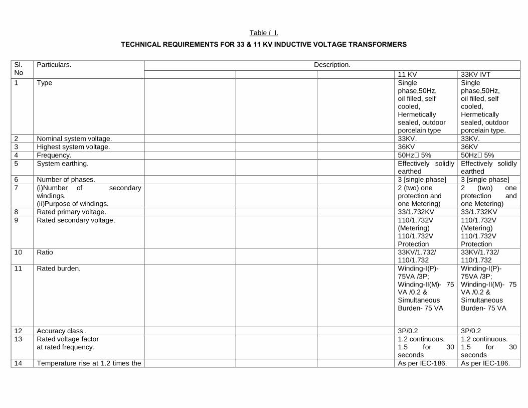
Table – I.
TECHNICAL REQUIREMENTS FOR 33 & 11 KV INDUCTIVE VOLTAGE TRANSFORMERS
Sl. No
Particulars. Description. 11 KV 33KV IVT
1 Type Single phase,50Hz, oil filled, self cooled, Hermetically sealed, outdoor porcelain type
Single phase,50Hz, oil filled, self cooled, Hermetically sealed, outdoor porcelain type.
2 Nominal system voltage. 33KV. 33KV. 3 Highest system voltage. 36KV 36KV 4 Frequency. 50Hz 5% 50Hz 5% 5 System earthing. Effectively solidly
earthed Effectively solidly earthed
6 Number of phases. 3 [single phase] 3 [single phase] 7 (i)Number of secondary
windings. (ii)Purpose of windings.
2 (two) one protection and one Metering)
2 (two) one protection and one Metering)
8 Rated primary voltage. 33/1.732KV 33/1.732KV 9 Rated secondary voltage. 110/1.732V
(Metering) 110/1.732V Protection
110/1.732V (Metering) 110/1.732V Protection
10 Ratio 33KV/1.732/ 110/1.732
33KV/1.732/ 110/1.732
11 Rated burden. Winding-I(P)- 75VA /3P; Winding-II(M)- 75 VA /0.2 & Simultaneous Burden- 75 VA
Winding-I(P)- 75VA /3P; Winding-II(M)- 75 VA /0.2 & Simultaneous Burden- 75 VA
12 Accuracy class . 3P/0.2 3P/0.2 13 Rated voltage factor
at rated frequency. 1.2 continuous.
1.5 for 30 seconds
1.2 continuous. 1.5 for 30 seconds
14 Temperature rise at 1.2 times the As per IEC-186. As per IEC-186.
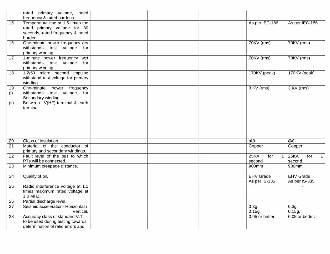
rated primary voltage, rated frequency & rated burdens.
15 Temperature rise at 1.5 times the rated primary voltage for 30 seconds, rated frequency & rated burden.
As per IEC-186 As per IEC-186
16 One-minute power frequency dry withstands test voltage for primary winding.
70KV (rms) 70KV (rms)
17 1-minute power frequency wet withstands test voltage for primary winding.
70KV (rms) 70KV (rms)
18
1.2/50 micro second impulse withstand test voltage for primary winding
170KV (peak) 170KV (peak)
19 (i) (ii)
One-minute power frequency withstands test voltage for Secondary winding Between LV(HF) terminal & earth terminal
3 KV (rms) 3 KV (rms)
20 Class of insulation. ‘A’ ‘A’ 21 Material of the conductor of
primary and secondary windings. Copper Copper
22 Fault level of the bus to which PTs will be connected.
25KA for 1 second
25KA for 1 second.
23 Minimum creepage distance. 900mm
900mm
24 Quality of oil. EHV Grade As per IS-335
EHV Grade As per IS-335
25 Radio interference voltage at 1.1 times maximum rated voltage at 1.0 MHZ.
-
26 Partial discharge level. 27 Seismic acceleration- Horizontal –
Vertical. 0.3g.
0.15g. 0.3g. 0.15g.
28 Accuracy class of standard V.T. to be used during testing towards determination of ratio errors and
0.05 or better.
0.05 or better.

phase angle errors for metering windings.
29. Capacitance (Pf) -
Signature of the tenderer with seal and date.

VOL-II(TS) E5-VII-ISOLATOR Page 1 of 14
TECHNICAL SPECIFICATION FOR
33 KV & 11 KV ISOLATOR
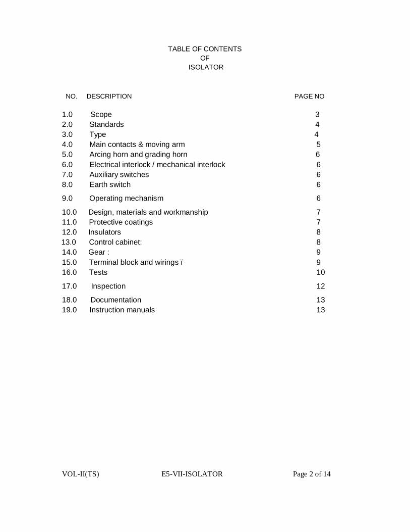
VOL-II(TS) E5-VII-ISOLATOR Page 2 of 14
TABLE OF CONTENTS OF
ISOLATOR NO. DESCRIPTION PAGE NO 1.0 Scope 3 2.0 Standards 4 3.0 Type 4 4.0 Main contacts & moving arm 5 5.0 Arcing horn and grading horn 6 6.0 Electrical interlock / mechanical interlock 6 7.0 Auxiliary switches 6 8.0 Earth switch 6
9.0 Operating mechanism 6
10.0 Design, materials and workmanship 7 11.0 Protective coatings 7 12.0 Insulators 8
13.0 Control cabinet: 8 14.0 Gear : 9 15.0 Terminal block and wirings – 9 16.0 Tests 10
17.0 Inspection 12
18.0 Documentation 13 19.0 Instruction manuals 13

VOL-II(TS) E5-VII-ISOLATOR Page 3 of 14
TECHNICAL SPECIFICATION FOR 33 KV & 11 KV ISOLATOR 1.0 SCOPE
This specification provides for design, manufacturer, testing at manufacturer’s Works and delivery ,supervision of erection, commissioning of outdoor station type 33kV & 11kV, 3 phase triple pole double break gang operated centre rotating type (Single Isolator with / without earth switches, with electrical interlock (castle key), insulators and complete in all respect with bimetallic connectors arcing horns operating mechanism, auxiliary switches, indicating devices, fixing detail etc. as described hereinafter. Double Tandem operating GI pipes (40mm Dia. medium gauge) & down pipe of 50mm dia, medium gauge GI pipe has to be used.
The material offered shall be procured from short listed vendor at E-23 and shall have been successfully Type Tested during last five years on the date of bid opening. The Type Test reports shall be submitted along with the bid.
1.1 Main features Sl.No Type 33kV 11kV 1 Main switch Double end break Centre post rotating,
gang operated 2 Service Outdoor 3 Applicable standard IS : 9921 / IEC-129/IEC-62271-102 4 Pole 3 pole gang operator 5 Rated voltage nominal/
Maximum 33/36 kV 11/12 kV
6 Rated Frequency 50 Hz + 5% 7 System earthing Effectively earthed 8 Temperature rise As per relevant IS/IEC publication 9 Insulation level
impulse with stand voltage
a) Across Isolating distance 195 kVpeak 85 kVpeak b) To earth & between poles 170 kVpeak 75 kVpeak 10 1 minute
power frequency with stand voltage
a) Across Isolating distance 80 kVpeak 32 kVpeak b) To earth & between poles 70 kVpeak 28 kVpeak 11 Rated current in Amp 1250 800
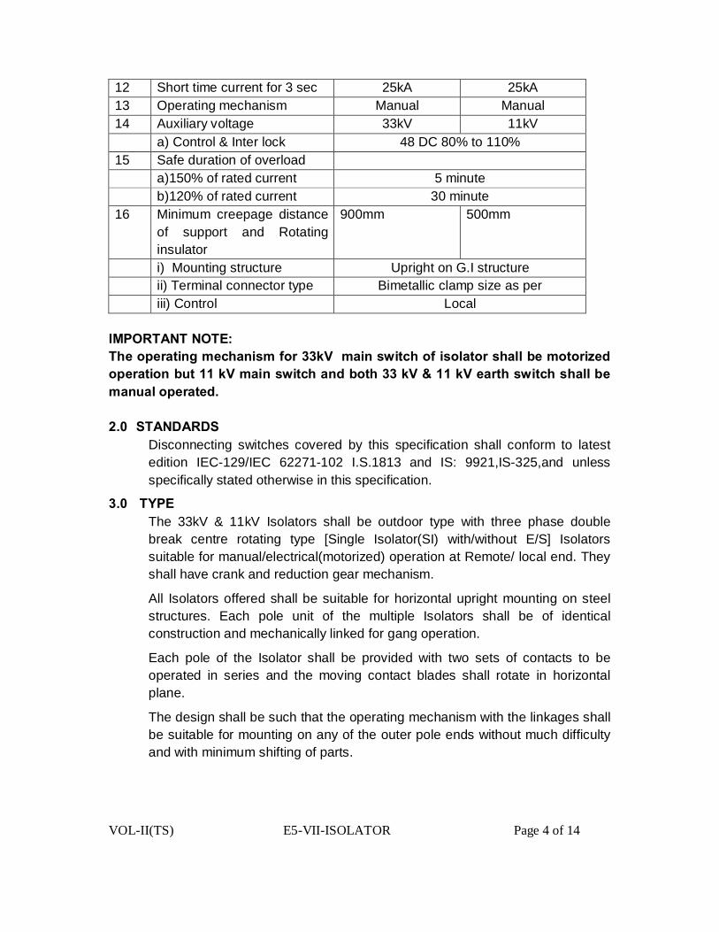
VOL-II(TS) E5-VII-ISOLATOR Page 4 of 14
12 Short time current for 3 sec 25kA 25kA 13 Operating mechanism Manual Manual 14 Auxiliary voltage 33kV 11kV a) Control & Inter lock 48 DC 80% to 110% 15 Safe duration of overload a)150% of rated current 5 minute b)120% of rated current 30 minute 16 Minimum creepage distance
of support and Rotating insulator
900mm 500mm
i) Mounting structure Upright on G.I structure ii) Terminal connector type Bimetallic clamp size as per iii) Control Local
IMPORTANT NOTE: The operating mechanism for 33kV main switch of isolator shall be motorized operation but 11 kV main switch and both 33 kV & 11 kV earth switch shall be manual operated. 2.0 STANDARDS
Disconnecting switches covered by this specification shall conform to latest edition IEC-129/IEC 62271-102 I.S.1813 and IS: 9921,IS-325,and unless specifically stated otherwise in this specification.
3.0 TYPE The 33kV & 11kV Isolators shall be outdoor type with three phase double break centre rotating type [Single Isolator(SI) with/without E/S] Isolators suitable for manual/electrical(motorized) operation at Remote/ local end. They shall have crank and reduction gear mechanism.
All Isolators offered shall be suitable for horizontal upright mounting on steel structures. Each pole unit of the multiple Isolators shall be of identical construction and mechanically linked for gang operation.
Each pole of the Isolator shall be provided with two sets of contacts to be operated in series and the moving contact blades shall rotate in horizontal plane.
The design shall be such that the operating mechanism with the linkages shall be suitable for mounting on any of the outer pole ends without much difficulty and with minimum shifting of parts.
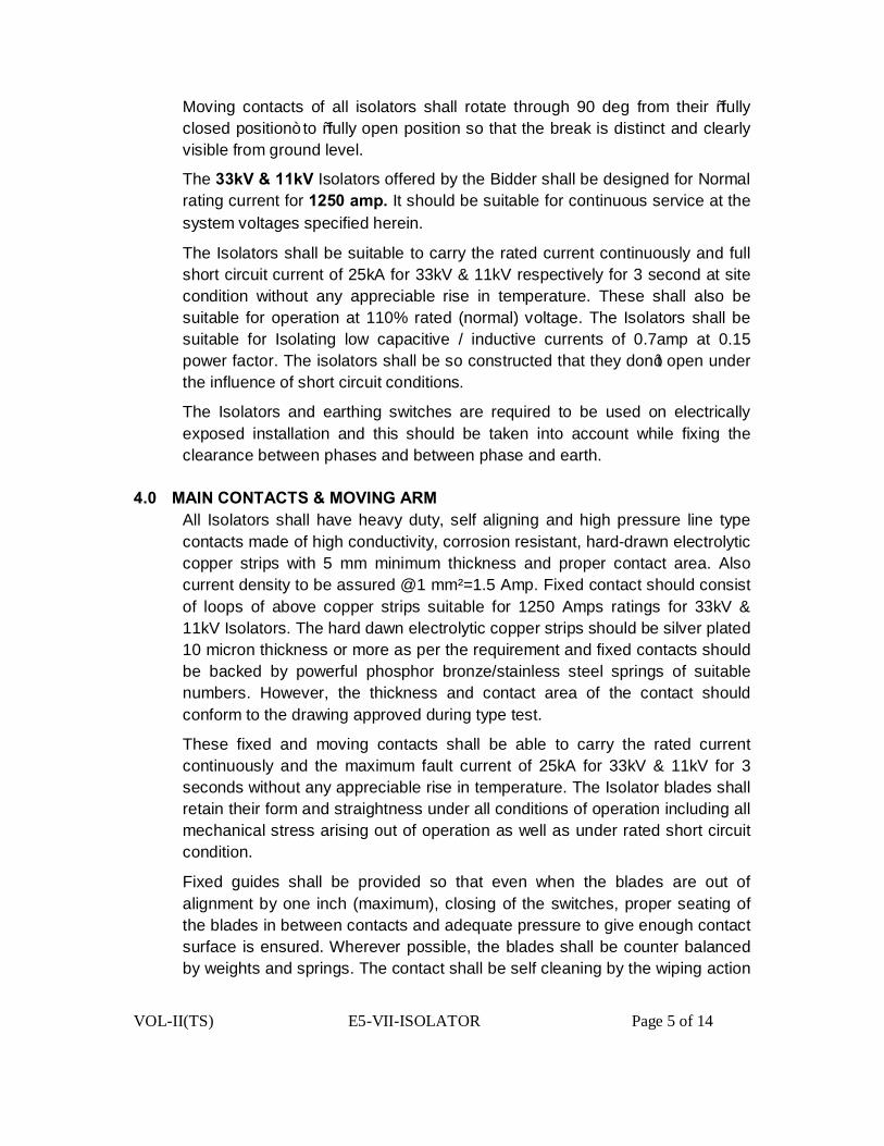
VOL-II(TS) E5-VII-ISOLATOR Page 5 of 14
Moving contacts of all isolators shall rotate through 90 deg from their “fully closed position” to “fully open position so that the break is distinct and clearly visible from ground level.
The 33kV & 11kV Isolators offered by the Bidder shall be designed for Normal rating current for 1250 amp. It should be suitable for continuous service at the system voltages specified herein.
The Isolators shall be suitable to carry the rated current continuously and full short circuit current of 25kA for 33kV & 11kV respectively for 3 second at site condition without any appreciable rise in temperature. These shall also be suitable for operation at 110% rated (normal) voltage. The Isolators shall be suitable for Isolating low capacitive / inductive currents of 0.7amp at 0.15 power factor. The isolators shall be so constructed that they don’t open under the influence of short circuit conditions.
The Isolators and earthing switches are required to be used on electrically exposed installation and this should be taken into account while fixing the clearance between phases and between phase and earth.
4.0 MAIN CONTACTS & MOVING ARM All Isolators shall have heavy duty, self aligning and high pressure line type contacts made of high conductivity, corrosion resistant, hard-drawn electrolytic copper strips with 5 mm minimum thickness and proper contact area. Also current density to be assured @1 mm²=1.5 Amp. Fixed contact should consist of loops of above copper strips suitable for 1250 Amps ratings for 33kV & 11kV Isolators. The hard dawn electrolytic copper strips should be silver plated 10 micron thickness or more as per the requirement and fixed contacts should be backed by powerful phosphor bronze/stainless steel springs of suitable numbers. However, the thickness and contact area of the contact should conform to the drawing approved during type test.
These fixed and moving contacts shall be able to carry the rated current continuously and the maximum fault current of 25kA for 33kV & 11kV for 3 seconds without any appreciable rise in temperature. The Isolator blades shall retain their form and straightness under all conditions of operation including all mechanical stress arising out of operation as well as under rated short circuit condition.
Fixed guides shall be provided so that even when the blades are out of alignment by one inch (maximum), closing of the switches, proper seating of the blades in between contacts and adequate pressure to give enough contact surface is ensured. Wherever possible, the blades shall be counter balanced by weights and springs. The contact shall be self cleaning by the wiping action
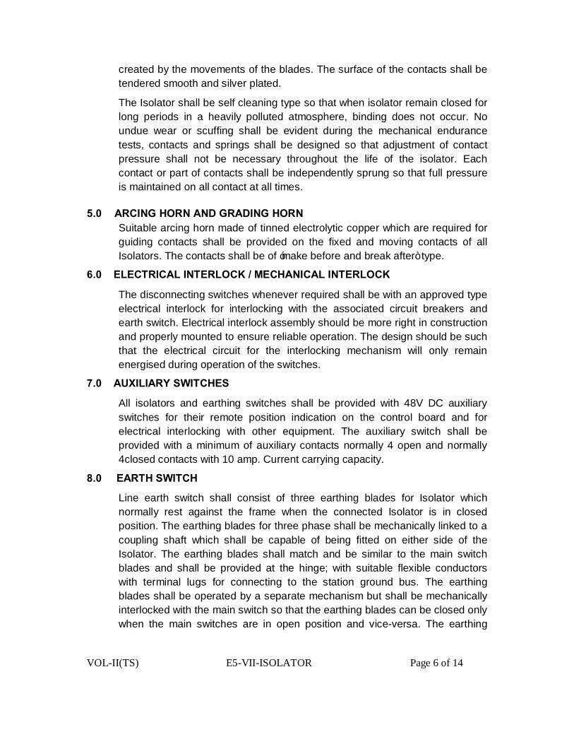
VOL-II(TS) E5-VII-ISOLATOR Page 6 of 14
created by the movements of the blades. The surface of the contacts shall be tendered smooth and silver plated.
The Isolator shall be self cleaning type so that when isolator remain closed for long periods in a heavily polluted atmosphere, binding does not occur. No undue wear or scuffing shall be evident during the mechanical endurance tests, contacts and springs shall be designed so that adjustment of contact pressure shall not be necessary throughout the life of the isolator. Each contact or part of contacts shall be independently sprung so that full pressure is maintained on all contact at all times.
5.0 ARCING HORN AND GRADING HORN Suitable arcing horn made of tinned electrolytic copper which are required for guiding contacts shall be provided on the fixed and moving contacts of all Isolators. The contacts shall be of ‘make before and break after” type.
6.0 ELECTRICAL INTERLOCK / MECHANICAL INTERLOCK
The disconnecting switches whenever required shall be with an approved type electrical interlock for interlocking with the associated circuit breakers and earth switch. Electrical interlock assembly should be more right in construction and properly mounted to ensure reliable operation. The design should be such that the electrical circuit for the interlocking mechanism will only remain energised during operation of the switches.
7.0 AUXILIARY SWITCHES
All isolators and earthing switches shall be provided with 48V DC auxiliary switches for their remote position indication on the control board and for electrical interlocking with other equipment. The auxiliary switch shall be provided with a minimum of auxiliary contacts normally 4 open and normally 4closed contacts with 10 amp. Current carrying capacity.
8.0 EARTH SWITCH
Line earth switch shall consist of three earthing blades for Isolator which normally rest against the frame when the connected Isolator is in closed position. The earthing blades for three phase shall be mechanically linked to a coupling shaft which shall be capable of being fitted on either side of the Isolator. The earthing blades shall match and be similar to the main switch blades and shall be provided at the hinge; with suitable flexible conductors with terminal lugs for connecting to the station ground bus. The earthing blades shall be operated by a separate mechanism but shall be mechanically interlocked with the main switch so that the earthing blades can be closed only when the main switches are in open position and vice-versa. The earthing

VOL-II(TS) E5-VII-ISOLATOR Page 7 of 14
blades shall be gang operated and all the three blades will operate simultaneously.
9.0 OPERATING MACHANISM The operating mechanism shall be simple and shall ensure quick and effective 1000 operation. The design shall be such as to enable one man to operate it with nominal effort. The operating mechanism box shall be made out of Aluminum extruded (Aluminum Alloy) sections of minimum 3mm thickness.
The Isolator blades shall be in positive continuous control throughout the entire cycles of operation. The operating rods and pipes shall be rigid enough to maintain positive control under most adverse conditions and to withstand all torsional and bending stresses arising from operation. Operation of the switches at any speed should not result in improper functioning, in displacement of parts / machines after final adjustment has been made. All holes in cranks, linkages etc. having moving pins shall be drilled and fitted accurately so as to prevent slackness and lost motion.
Provision shall be made for padlocking the operating mechanism of disconnecting and earth switches in both open and closed positions.
Bearings shall be ball and roller type shall be protected from weather and dust by means of cover and grease retainers. Bearings pressures shall be kept low to ensure long life and care of operation.
Each operated isolator shall be driven as well as manually operated and shall be complete with local selector switch and open / close push buttons. The function of all control facilitates operating isolators.
10.0 DESIGN, MATERIALS AND WORKMANSHIP
The live parts shall be designed to eliminate sharp points, edges and similar corona producing surfaces, where this is impracticable, adequate shields to be provided. All ferrous metal parts shall be hot dip galvanized, as per IS 2629.All metal parts shall be of such materials or treated in such a way so as to avoid rust, corrosion and deterioration due to continued exposure to atmosphere and rain. All current carrying parts shall be made from high conductivity electrolytic Copper.
Bolts, screws and pins shall be provided with standard locking device viz. Locknuts, spring washers, keys etc. and when used with current carrying parts, they shall be made of copper silicon or other high conductivity and wear resistant alloys.
The switches should not need lubrication of any parts except at very long interval of five year minimum.
11.0 PROTECTIVE COATINGS

VOL-II(TS) E5-VII-ISOLATOR Page 8 of 14
All ferrous parts including bolts, nuts and washers of the switches assembly shall be galvanized to withstand at least six times one minute dips in Copper Sulphate solution of requisite strength (Pierce tests) except the threaded portions which should withstand four dips.
12.0 INSULATORS
Support insulators for all type of isolators shall be of solid core type. The insulator shall be made of homogeneous and vitreous porcelain of high mechanical and dielectric strength. It shall have sufficient mechanical strength to sustain electrical and mechanical loading on account of wind load, short circuit forces etc. Glazing of the porcelains shall be of uniform dark brown color with a smooth surface arranged to shed away raise water. The porcelain shall be free from laminations and other flaws or imperfections that might affect the mechanical or dielectric quality. It shall be thoroughly vitrified, tough and impervious to moisture. The porcelain and metal ports shall be assembled in such a manner and with such material that any thermal differential expansion between the metal and porcelain parts throughout the range of temperature specified in this specification shall not loosen the parts or create under internal stresses which may affect the mechanical or electrical strength or rigidity. The assembly shall not have excessive concentration of electrical stresses in any section or across leakage surfaces. The cement used shall not give rise to chemical reaction with metal fittings. The insulator shall be suitable for water washing by rain or artificial means in service condition. Profile of the insulator shall also conform to IEC-815. Insulator shall have a minimum cantilever strength of 800 kgs. Caps to be provided on top of the insulator shall be of high grade cast iron or malleable steel casting. It shall be machine faced and hot dip galvanized. The cap shall have four numbers of tapped holes spaced on a pitch circle diameter of 76 mm. The holes shall be suitable for bolts with threads having anti corrosive protection. The effective depth of threads shall not be less than the nominal diameter of the bolt. The cap shall be so designed that it shall be free from visible corona and shall have radio interference level within 500 micro volts. Casing shall be free from blow holes cracks and such other defects.
13.0 CONTROL CABINET:
The control cabinet of the operating mechanism shall be made out of Aluminum sheet of minimum 3mm thickness. Hinged door shall be provided with pad locking arrangement. Sloping rain hood shall be provided to cover all sides. 15 mm thick neoprene or better type of gaskets shall be provided to
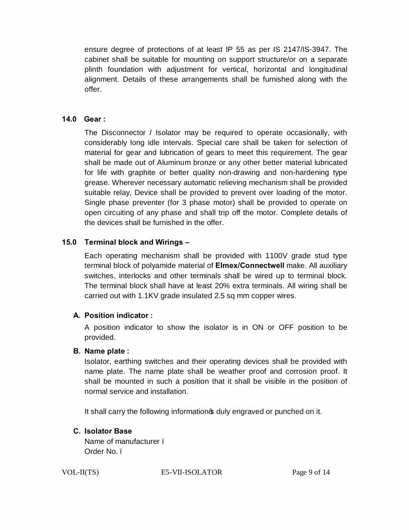
VOL-II(TS) E5-VII-ISOLATOR Page 9 of 14
ensure degree of protections of at least IP 55 as per IS 2147/IS-3947. The cabinet shall be suitable for mounting on support structure/or on a separate plinth foundation with adjustment for vertical, horizontal and longitudinal alignment. Details of these arrangements shall be furnished along with the offer.
14.0 Gear :
The Disconnector / Isolator may be required to operate occasionally, with considerably long idle intervals. Special care shall be taken for selection of material for gear and lubrication of gears to meet this requirement. The gear shall be made out of Aluminum bronze or any other better material lubricated for life with graphite or better quality non-drawing and non-hardening type grease. Wherever necessary automatic relieving mechanism shall be provided suitable relay, Device shall be provided to prevent over loading of the motor. Single phase preventer (for 3 phase motor) shall be provided to operate on open circuiting of any phase and shall trip off the motor. Complete details of the devices shall be furnished in the offer.
15.0 Terminal block and Wirings –
Each operating mechanism shall be provided with 1100V grade stud type terminal block of polyamide material of Elmex/Connectwell make. All auxiliary switches, interlocks and other terminals shall be wired up to terminal block. The terminal block shall have at least 20% extra terminals. All wiring shall be carried out with 1.1KV grade insulated 2.5 sq mm copper wires.
A. Position indicator :
A position indicator to show the isolator is in ON or OFF position to be provided.
B. Name plate : Isolator, earthing switches and their operating devices shall be provided with name plate. The name plate shall be weather proof and corrosion proof. It shall be mounted in such a position that it shall be visible in the position of normal service and installation. It shall carry the following information’s duly engraved or punched on it.
C. Isolator Base
Name of manufacturer – Order No. –

VOL-II(TS) E5-VII-ISOLATOR Page 10 of 14
Type Designation – Manufacturers serial No. – Rated voltage – Rated normal current – Rated short time current (rms) and duration – Rated short time peak current (kApeak) Weight
D. Earthing Switch Name of manufacturer – Order No. – Type Designation – Manufacturers serial No. – Rated voltage – Rated normal current – Rated short time current (rms) and duration Rated short time peak current (kApeak) Weight
E. Operating Device Name of manufacturer – Order No. Type Designation – Reduction gear ratio – AC motor 1) Rated auxiliary voltage
2) Starting current 3) Designation of AC motor as per I.S 4722/325 4) Starting torque at 80% of supply voltage 5) Over travel in degrees after cutting off supply
Total operating time in seconds 6) Close operation – Electrical 7) Open operation – Electrical 8) Open operation – Manual All components shall be given adequate treatment of climate proofing as per IS:3202 so as to withstand corrosive and severe service conditions.
All metal parts not suitable for painting such as structural steel, pipes, rods, levers, linkages, nuts and bolts used in other than current path etc. shall be hot dip galvanized as per IS -2629.
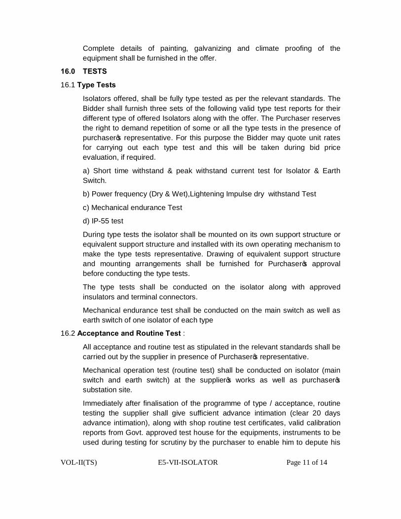
VOL-II(TS) E5-VII-ISOLATOR Page 11 of 14
Complete details of painting, galvanizing and climate proofing of the equipment shall be furnished in the offer.
16.0 TESTS
16.1 Type Tests
Isolators offered, shall be fully type tested as per the relevant standards. The Bidder shall furnish three sets of the following valid type test reports for their different type of offered Isolators along with the offer. The Purchaser reserves the right to demand repetition of some or all the type tests in the presence of purchaser’s representative. For this purpose the Bidder may quote unit rates for carrying out each type test and this will be taken during bid price evaluation, if required.
a) Short time withstand & peak withstand current test for Isolator & Earth Switch.
b) Power frequency (Dry & Wet),Lightening Impulse dry withstand Test
c) Mechanical endurance Test
d) IP-55 test
During type tests the isolator shall be mounted on its own support structure or equivalent support structure and installed with its own operating mechanism to make the type tests representative. Drawing of equivalent support structure and mounting arrangements shall be furnished for Purchaser’s approval before conducting the type tests.
The type tests shall be conducted on the isolator along with approved insulators and terminal connectors.
Mechanical endurance test shall be conducted on the main switch as well as earth switch of one isolator of each type
16.2 Acceptance and Routine Test :
All acceptance and routine test as stipulated in the relevant standards shall be carried out by the supplier in presence of Purchaser’s representative.
Mechanical operation test (routine test) shall be conducted on isolator (main switch and earth switch) at the supplier’s works as well as purchaser’s substation site.
Immediately after finalisation of the programme of type / acceptance, routine testing the supplier shall give sufficient advance intimation (clear 20 days advance intimation), along with shop routine test certificates, valid calibration reports from Govt. approved test house for the equipments, instruments to be used during testing for scrutiny by the purchaser to enable him to depute his

VOL-II(TS) E5-VII-ISOLATOR Page 12 of 14
representative for witnessing the tests. If there will be any discrepancies in the shop routine test certificates and calibration reports furnished by the firm then after settlement of the discrepancies only, purchaser’s representative will be deputed for witnessing the tests.
Special tests proposed to be conducted (if decided to conduct) as type test on isolators, are given at TABLE-1 IN this chapter. These special type test charges shall be quoted along with all other type tests as per relevant IEC standard and these charges shall be included in the total bid price.
Test certificates of various items including but not limited to the following shall be furnished at the time of routine tests.
i. Chemical analysis of copper along with a copy of excise certificate indicating genuine source of procurement of electrolytic grade copper.
ii Bearings iii Fasteners iv Universal / swivel joint coupling v Insulators vi Gears vii Auxiliary switch viii Overload / single phase preventer relay ix Interlocking devices x Terminal block xi Any other item
17.0 INSPECTION
i) The Purchaser shall have access at all times to the works and all other places of manufacture, where the dis-connectors, earth switches and associated equipment are being manufactured and the supplier shall provide all facilities for unrestricted inspection of the works raw materials manufacture of all the accessories and for conducting necessary tests as detailed herein.
ii) The supplier shall keep the purchaser informed in advance of the time of
starting of the progress of manufacture of equipment in its various stages so that arrangements could be made for inspection.
iii) No material shall be dispatched from its point of manufacture unless the
material has been satisfactorily inspected and tested.
iv) The acceptance of any quantity of the equipment shall in no way relieve the supplier of his responsibility for meeting all the requirements of this

VOL-II(TS) E5-VII-ISOLATOR Page 13 of 14
specification and shall not prevent subsequent rejection if such equipment are later found to be defective.
18.0 DOCUMENTATION
All drawings shall conform to relevant international standards organization (ISO). All drawings shall be in ink and suitable for micro filming. All dimensions and data shall be in S.I. Units.
List of Drawings and Documents
The Bidder shall furnish four sets of following drawings / documents along with his offer.
a) General outline and assembly drawings of the dis-connector operating mechanism, structure, insulator and terminal connector.
b) Sectional views and descriptive details of items such as moving blades, contacts, arms contact pressure, contact support bearing housing of bearings, balancing of heights, phase coupling pipes, base plate, operating shaft, guides, swivel joint operating mechanism and its components etc.
c) Loading diagram d) Drawings with structure for the purpose of type tests. e) Name plate. f) Schematic drawing. g) Type test reports. h) Test reports, literature, pamphlets of the bought out items and raw material.
The contractor should submit two sets of final versions of all the above said drawings for Purchaser’s approval. The purchaser shall communicate his comments / approval on the drawings. The supplier shall, if necessary, modify the drawings and resubmit the modified drawings for Purchaser’s approval within two weeks from the date of comments. After receipt of approval the supplier shall within three weeks submit 15 prints and two good qualities re-producible of the approved drawings for purchaser’s use. Six sets of the type test reports, duly signed by the Purchaser shall be submitted by the supplier for distribution, before commencement of supply Adequate copies of acceptance and routine test certificates, duly approved by the Purchaser shall accompany the despatched consignment.
The manufacturing of the equipment shall be strictly in accordance with the approved drawings and no deviation shall be permitted without the written approval of the purchaser. All manufacturing and fabrication work in connection with the equipment prior to the approval of the drawing shall be at the supplier risk.
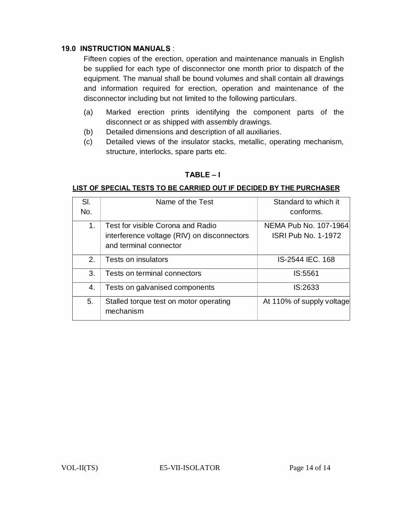
VOL-II(TS) E5-VII-ISOLATOR Page 14 of 14
19.0 INSTRUCTION MANUALS : Fifteen copies of the erection, operation and maintenance manuals in English be supplied for each type of disconnector one month prior to dispatch of the equipment. The manual shall be bound volumes and shall contain all drawings and information required for erection, operation and maintenance of the disconnector including but not limited to the following particulars.
(a) Marked erection prints identifying the component parts of the disconnect or as shipped with assembly drawings.
(b) Detailed dimensions and description of all auxiliaries. (c) Detailed views of the insulator stacks, metallic, operating mechanism,
structure, interlocks, spare parts etc.
TABLE – I
LIST OF SPECIAL TESTS TO BE CARRIED OUT IF DECIDED BY THE PURCHASER
Sl. No.
Name of the Test Standard to which it conforms.
1. Test for visible Corona and Radio interference voltage (RIV) on disconnectors and terminal connector
NEMA Pub No. 107-1964 ISRI Pub No. 1-1972
2. Tests on insulators IS-2544 IEC. 168
3. Tests on terminal connectors IS:5561
4. Tests on galvanised components IS:2633
5. Stalled torque test on motor operating mechanism
At 110% of supply voltage

VOL-II(TS) E5-VIII- AB SWITCH Page-1 of 16
TECHNICAL SPECIFICATION
FOR AB SWITCH

VOL-II(TS) E5-VIII- AB SWITCH Page-2 of 16
TABLE OF CONTENTS
OF AB SWITCH
NO.DESCRIPTION PAGE NO
1.0 Scope 3
2.0 Standards 3
3.0 Technicaldetails 4
4.0 Tests&Testcertificate 6
5.0 Guranteed Technical Particulars 6
6.0 Completenessofequipment 6
7.0 Inspection 7
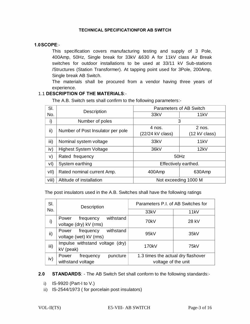
VOL-II(TS) E5-VIII- AB SWITCH Page-3 of 16
TECHNICAL SPECIFICATIONFOR AB SWITCH
1.0 SCOPE:- This specification covers manufacturing testing and supply of 3 Pole, 400Amp, 50Hz, Single break for 33kV &630 A for 11kV class Air Break switches for outdoor installations to be used at 33/11 kV Sub-stations /Structures (Station Transformer). At tapping point used for 3Pole, 200Amp, Single break AB Switch. The materials shall be procured from a vendor having three years of experience.
1.1 DESCRIPTION OF THE MATERIALS:-
The A.B. Switch sets shall confirm to the following parameters:-
Sl. No. Description
Parameters of AB Switch 33kV 11kV
i) Number of poles 3
ii) Number of Post Insulator per pole 4 nos. (22/24 kV class)
2 nos. (12 kV class)
iii) Nominal system voltage 33kV 11kV iv) Highest System Voltage 36kV 12kV v) Rated frequency 50Hz vI) System earthing Effectively earthed.
vII) Rated nominal current Amp. 400Amp 630Amp
viii) Altitude of installation Not exceeding 1000 M
The post insulators used in the A.B. Switches shall have the following ratings
Sl. No. Description
Parameters P.I. of AB Switches for
33kV 11kV
i) Power frequency withstand voltage (dry) kV (rms) 70kV 28 kV
ii) Power frequency withstand voltage (wet) kV (rms) 95kV 35kV
iii) Impulse withstand voltage (dry) kV (peak)
170kV 75kV
iv) Power frequency puncture withstand voltage
1.3 times the actual dry flashover voltage of the unit
2.0 STANDARDS: - The AB Switch Set shall conform to the following standards:-
i) IS-9920 (Part-I to V.) ii) IS-2544/1973 ( for porcelain post insulators)
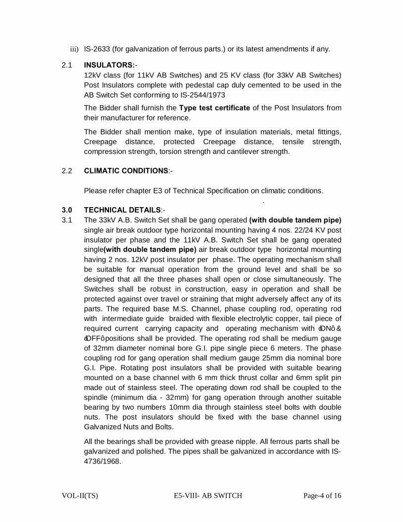
VOL-II(TS) E5-VIII- AB SWITCH Page-4 of 16
iii) IS-2633 (for galvanization of ferrous parts.) or its latest amendments if any.
2.1 INSULATORS:- 12kV class (for 11kV AB Switches) and 25 KV class (for 33kV AB Switches) Post Insulators complete with pedestal cap duly cemented to be used in the AB Switch Set conforming to IS-2544/1973
The Bidder shall furnish the Type test certificate of the Post Insulators from their manufacturer for reference.
The Bidder shall mention make, type of insulation materials, metal fittings, Creepage distance, protected Creepage distance, tensile strength, compression strength, torsion strength and cantilever strength.
2.2 CLIMATIC CONDITIONS:-
Please refer chapter E3 of Technical Specification on climatic conditions.
. 3.0 TECHNICAL DETAILS:- 3.1 The 33kV A.B. Switch Set shall be gang operated (with double tandem pipe)
single air break outdoor type horizontal mounting having 4 nos. 22/24 KV post insulator per phase and the 11kV A.B. Switch Set shall be gang operated single(with double tandem pipe) air break outdoor type horizontal mounting having 2 nos. 12kV post insulator per phase. The operating mechanism shall be suitable for manual operation from the ground level and shall be so designed that all the three phases shall open or close simultaneously. The Switches shall be robust in construction, easy in operation and shall be protected against over travel or straining that might adversely affect any of its parts. The required base M.S. Channel, phase coupling rod, operating rod with intermediate guide braided with flexible electrolytic copper, tail piece of required current carrying capacity and operating mechanism with ‘ON’ & ‘OFF’ positions shall be provided. The operating rod shall be medium gauge of 32mm diameter nominal bore G.I. pipe single piece 6 meters. The phase coupling rod for gang operation shall medium gauge 25mm dia nominal bore G.I. Pipe. Rotating post insulators shall be provided with suitable bearing mounted on a base channel with 6 mm thick thrust collar and 6mm split pin made out of stainless steel. The operating down rod shall be coupled to the spindle (minimum dia - 32mm) for gang operation through another suitable bearing by two numbers 10mm dia through stainless steel bolts with double nuts. The post insulators should be fixed with the base channel using Galvanized Nuts and Bolts.
All the bearings shall be provided with grease nipple. All ferrous parts shall be galvanized and polished. The pipes shall be galvanized in accordance with IS-4736/1968.
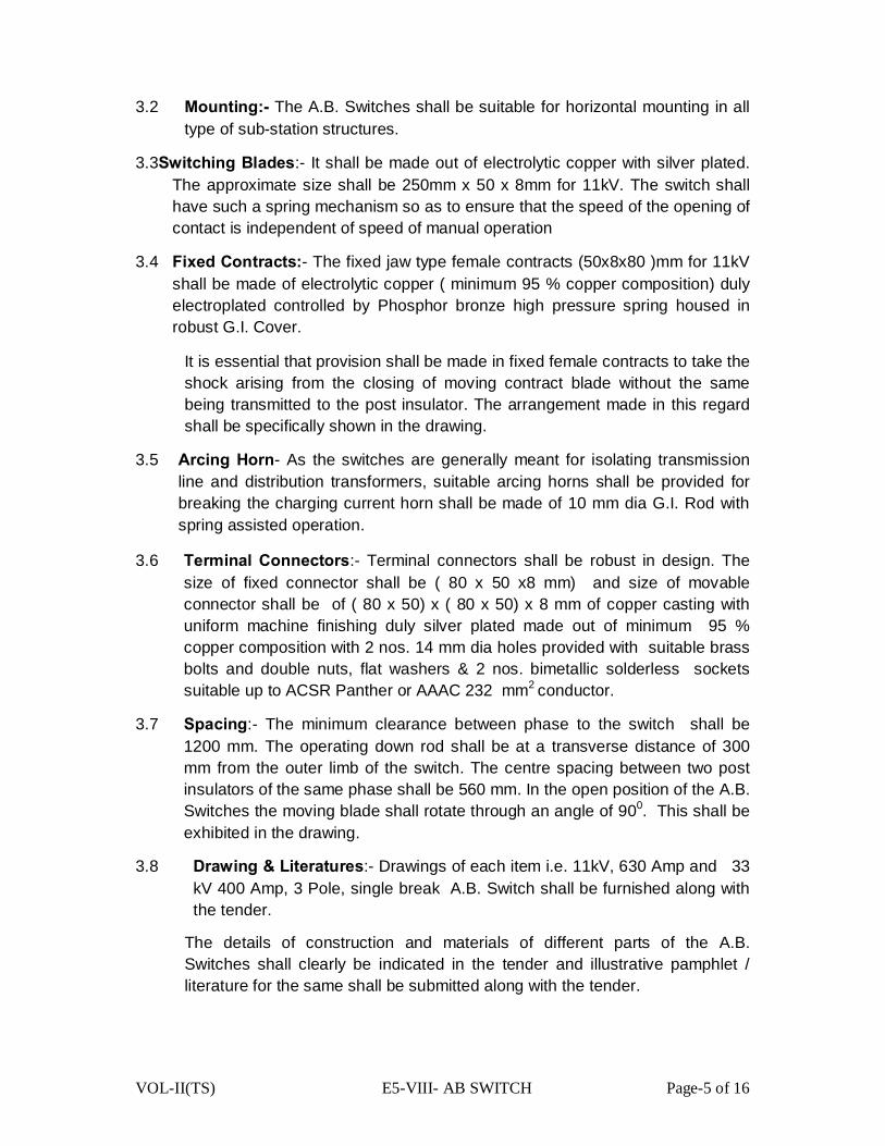
VOL-II(TS) E5-VIII- AB SWITCH Page-5 of 16
3.2 Mounting:- The A.B. Switches shall be suitable for horizontal mounting in all type of sub-station structures.
3.3Switching Blades:- It shall be made out of electrolytic copper with silver plated. The approximate size shall be 250mm x 50 x 8mm for 11kV. The switch shall have such a spring mechanism so as to ensure that the speed of the opening of contact is independent of speed of manual operation
3.4 Fixed Contracts:- The fixed jaw type female contracts (50x8x80 )mm for 11kV shall be made of electrolytic copper ( minimum 95 % copper composition) duly electroplated controlled by Phosphor bronze high pressure spring housed in robust G.I. Cover.
It is essential that provision shall be made in fixed female contracts to take the shock arising from the closing of moving contract blade without the same being transmitted to the post insulator. The arrangement made in this regard shall be specifically shown in the drawing.
3.5 Arcing Horn- As the switches are generally meant for isolating transmission line and distribution transformers, suitable arcing horns shall be provided for breaking the charging current horn shall be made of 10 mm dia G.I. Rod with spring assisted operation.
3.6 Terminal Connectors:- Terminal connectors shall be robust in design. The size of fixed connector shall be ( 80 x 50 x8 mm) and size of movable connector shall be of ( 80 x 50) x ( 80 x 50) x 8 mm of copper casting with uniform machine finishing duly silver plated made out of minimum 95 % copper composition with 2 nos. 14 mm dia holes provided with suitable brass bolts and double nuts, flat washers & 2 nos. bimetallic solderless sockets suitable up to ACSR Panther or AAAC 232 mm2 conductor.
3.7 Spacing:- The minimum clearance between phase to the switch shall be 1200 mm. The operating down rod shall be at a transverse distance of 300 mm from the outer limb of the switch. The centre spacing between two post insulators of the same phase shall be 560 mm. In the open position of the A.B. Switches the moving blade shall rotate through an angle of 900. This shall be exhibited in the drawing.
3.8 Drawing & Literatures:- Drawings of each item i.e. 11kV, 630 Amp and 33 kV 400 Amp, 3 Pole, single break A.B. Switch shall be furnished along with the tender.
The details of construction and materials of different parts of the A.B. Switches shall clearly be indicated in the tender and illustrative pamphlet / literature for the same shall be submitted along with the tender.

VOL-II(TS) E5-VIII- AB SWITCH Page-6 of 16
4.0 TESTS & TEST CERTIFICATE
4.1 Type Test:- Certificates for the following type tests conducted within five years proceeding to the date of opening of tender on prototype set of A.B Switch in a Govt. Approved Testing Laboratory preferably at CPRI, Bhopal/ Bangalore shall have to be submitted for reference and scrutiny.
i. Impulse voltage dry test ii. Power frequency voltage dry test iii. Power frequency voltage wet test iv. Temperature of resistance. v. Measurement of resistance. vi. Test to prove the capability of carrying the rated peak short circuit
current and the rated short time current. vii. Mainly active load breaking capacity test. viii. Transformer off-load breaking test. ix. Line charging breaking capacity test. x. Operation tests. xi. Mechanical endurance test. xii. Mechanical strength test for the post insulator as per IS-2544/1973. xiii. Test for galvanization of metal ( ferrous) parts as perm IS-2633/1973.
Besides, mechanical endurance test will have to be conduct on one set in the presence of our authorized person who shall be deputed to carryout acceptance tests before delivery of the materials.
4.2 Routine Tests:- The following routine tests shall have to be conducted on each
sets and results are to be furnished for consideration of deputing inspecting officer for inspection and conducting testing of the materials.
1. Power frequency voltage dry test 2. Measurement of resistance of main circuit 3. Tests to prove satisfactory operation. 4. Dimension check 5. Galvanization test.
5.0 GUARANTEED TECHNICAL PARTICULARS:- The tenderer shall furnish the guaranteed technical particulars duly filled in the format at E-21along with the tender.
6.0 COMPLETENESS OF EQUIPMENT:- Any fittings, accessories for apparatus which may not have been specifically mentioned in this specification but which are usual or necessary in equipment of similar plant shall be deemed to be included in the specification and shall be supplied by the Tender without extra charge. All plant and equipment shall be completed in all details whether such details are mentioned in the specification or not.

VOL-II(TS) E5-VIII- AB SWITCH Page-7 of 16
7.0INSPECTION:- Routine and acceptance tests shall be conducted at the place of manufacturer. The successful bidder has to furnish Routine test Certificateand guaranteed certificate for approval prior to offer of materials for inspection for each consignment of offer.
GUARANTEED TECHNICAL PARTICULARS FOR 33kV, 400A, 50 Hz,
5 POLE, SINGLE BREAK TYPE Sl. No Particulars Desired values
Bidder’s offer
1 2 3 4
1. Maker’s name and country of origin To be specified by the tenderer
2. Type of Switch Rotating type only
3. Suitable for mounting Horizontal only
4. Number of supporting Post Insulators per phase
4 nos. (22kV / 24kV Post Insulators per phase as per ISS-2544/1973)
5. Post Insulator.
a) Maker’s name and country of origin To be specified by the tenderer
b) Type of cementing To be quoted for original cemented only & as per IS-2544-1973 & relevant IEC.
c) One minute power frequency withstand voltage Dry
95kV rms.
d) One minute power frequency withstand voltage Wet
75kV rms.
e) Visible discharge voltage 27kV rms.
f) Dry Flashover Voltage To be specified by the tenderer
g) Power frequency puncture with stand voltage
1.3 times of actual dry flash over voltage
h) Impulse withstand voltage (switch in position) 170kV(peak)
i) Creepage distance (mm)
380 mm minimum. (actual Creepage distance for which type test have been conducted is to be specified by the tenderer

VOL-II(TS) E5-VIII- AB SWITCH Page-8 of 16
6.
Impulse withstand voltage for positive and negative polarity 1.2 / 50 mircro-second wave
a) Across the isolating distance 195kV(peak)
b) To earth & between poles 170kV(peak)
7. One minute power frequency withstand voltage
a) Across the isolating distance 80kV(rms)
b) To earth & between poles 70kV(rms)
8. Rated normal current and rated frequency 400 Amp 50 Hz
9. Rated short time current. 16kA( rms )
10. Rated short circuit making capacity 25kA(rms)
11. Rated peak withstand current 40kA( Peak )
12. Rated cable charging breaking capacity 40kA( rms )
13. Rated Transformer off load breaking capacity
16 Amp(rms)
14. Rated line charging breaking capacity 5.3 Amp( rms)
15. Minimum clearance between adjacent phases
a) Switch Closed ( centre to centre)
1200 mm
b) Switch Opened ( centre to edge of blade)
640 mm
16. Temperature rise
a)
Temperature rise shall not exceed the maximum limit as specified below at an ambient temperature not exceeding in 40 0 C

VOL-II(TS) E5-VIII- AB SWITCH Page-9 of 16
b) Copper contacts in air 650C
c)
Terminal of switch intended to be connected to external conductor by bolts
500C
17. Vertical Clearance from top of insulator cap to mounting channel
508 mm (minimum)
18. Type of Contact: -
a) Self aligned, high pressure jaw type fixed contacts of electrolytic copper of size 80 mm x 50 mm x 8 mm duly silver plated. Each contact should be revetted with three nos. Copper rivets with a bunch (minimum 3 mm thick) consisting of copper foils, each may vary from 0.15 mm to 0.25 mm. These total thickness of copper foils per jaw should be 6 mm. Jaw assemblies are to be bolted through stainless steel bolts and nuts with stainless steel flat and spring washer.
b) Solid rectangular blade type moving contact of electrolytic copper size 250 mm x 50 mm x 8 mm duly silver plated ensuring a minimum deposit of 10 micron of silver on copper contacts or as may be prescribed under relevant ISS / IEC.
c) Pressure spring to be used in jaw contacts shall be Stainless Steel having 8 nos of turn x 28 mm height x 14.4 mm diameter with 14 SWG wire (minimum six nos springs shall be used)
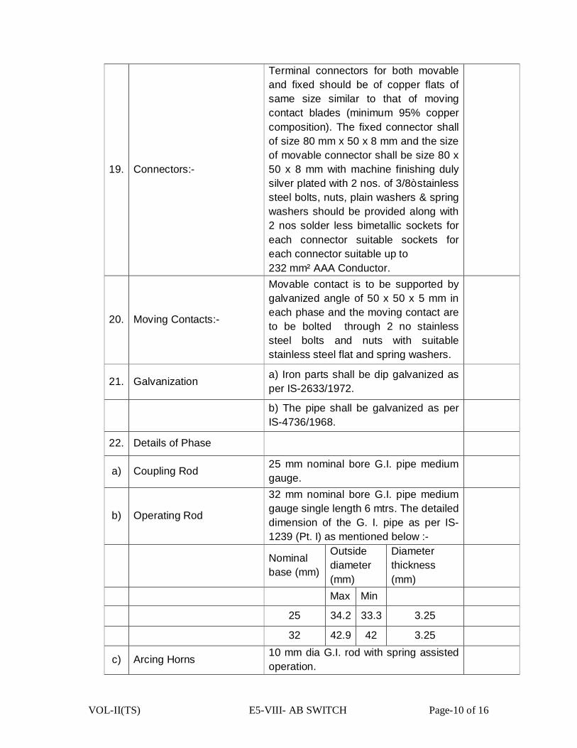
VOL-II(TS) E5-VIII- AB SWITCH Page-10 of 16
19. Connectors:-
Terminal connectors for both movable and fixed should be of copper flats of same size similar to that of moving contact blades (minimum 95% copper composition). The fixed connector shall of size 80 mm x 50 x 8 mm and the size of movable connector shall be size 80 x 50 x 8 mm with machine finishing duly silver plated with 2 nos. of 3/8” stainless steel bolts, nuts, plain washers & spring washers should be provided along with 2 nos solder less bimetallic sockets for each connector suitable sockets for each connector suitable up to 232 mm² AAA Conductor.
20. Moving Contacts:-
Movable contact is to be supported by galvanized angle of 50 x 50 x 5 mm in each phase and the moving contact are to be bolted through 2 no stainless steel bolts and nuts with suitable stainless steel flat and spring washers.
21. Galvanization a) Iron parts shall be dip galvanized as per IS-2633/1972.
b) The pipe shall be galvanized as per IS-4736/1968.
22. Details of Phase
a) Coupling Rod 25 mm nominal bore G.I. pipe medium gauge.
b) Operating Rod
32 mm nominal bore G.I. pipe medium gauge single length 6 mtrs. The detailed dimension of the G. I. pipe as per IS-1239 (Pt. I) as mentioned below :-
Nominal base (mm)
Outside diameter (mm)
Diameter thickness (mm)
Max Min
25 34.2 33.3 3.25
32 42.9 42 3.25
c) Arcing Horns 10 mm dia G.I. rod with spring assisted operation.
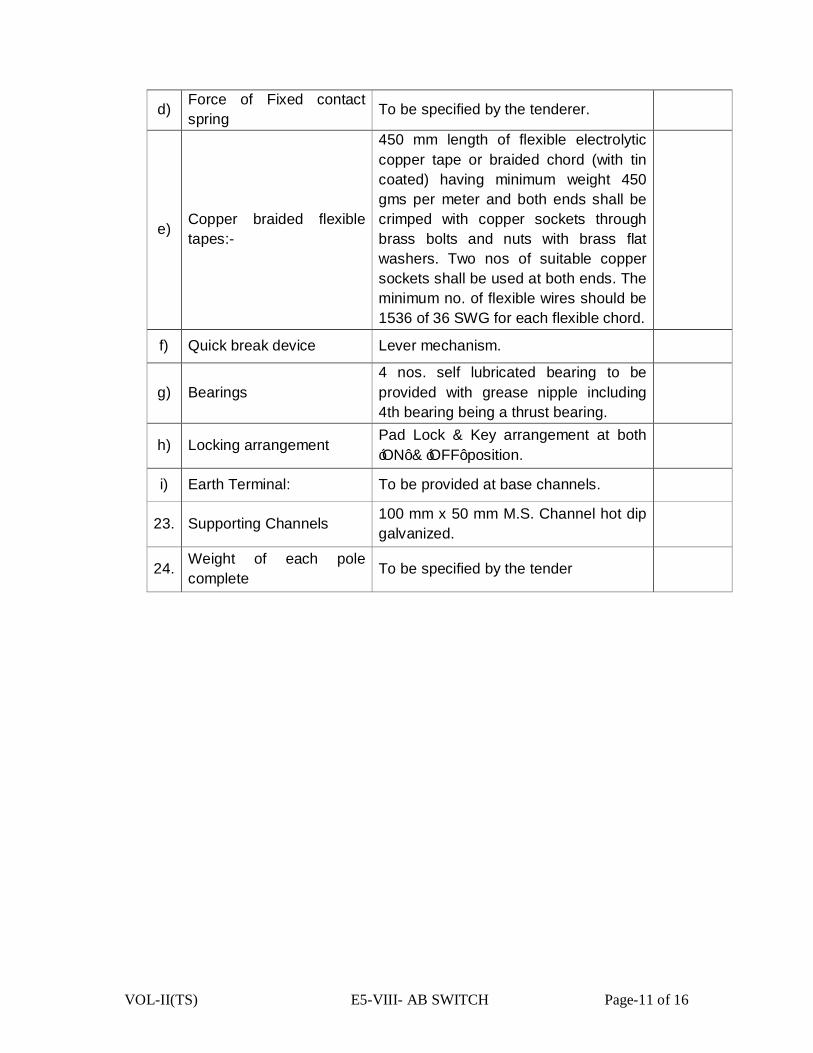
VOL-II(TS) E5-VIII- AB SWITCH Page-11 of 16
d) Force of Fixed contact spring To be specified by the tenderer.
e) Copper braided flexible tapes:-
450 mm length of flexible electrolytic copper tape or braided chord (with tin coated) having minimum weight 450 gms per meter and both ends shall be crimped with copper sockets through brass bolts and nuts with brass flat washers. Two nos of suitable copper sockets shall be used at both ends. The minimum no. of flexible wires should be 1536 of 36 SWG for each flexible chord.
f) Quick break device Lever mechanism.
g) Bearings 4 nos. self lubricated bearing to be provided with grease nipple including 4th bearing being a thrust bearing.
h) Locking arrangement Pad Lock & Key arrangement at both ‘ON’ & ‘OFF’ position.
i) Earth Terminal: To be provided at base channels.
23. Supporting Channels 100 mm x 50 mm M.S. Channel hot dip galvanized.
24. Weight of each pole complete To be specified by the tender
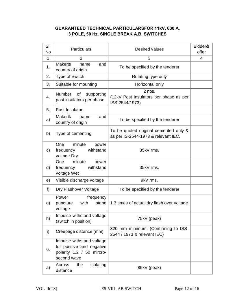
VOL-II(TS) E5-VIII- AB SWITCH Page-12 of 16
GUARANTEED TECHNICAL PARTICULARSFOR 11kV, 630 A, 3 POLE, 50 Hz, SINGLE BREAK A.B. SWITCHES
Sl. No Particulars Desired values Bidder’s
offer 1 2 3 4
1. Maker’s name and country of origin To be specified by the tenderer
2. Type of Switch Rotating type only
3. Suitable for mounting Horizontal only
4. Number of supporting post insulators per phase
2 nos. (12kV Post Insulators per phase as per ISS-2544/1973)
5. Post Insulator.
a) Maker’s name and country of origin To be specified by the tenderer
b) Type of cementing To be quoted original cemented only & as per IS-2544-1973 & relevant IEC.
c) One minute power frequency withstand voltage Dry
35kV rms.
d) One minute power frequency withstand voltage Wet
35kV rms.
e) Visible discharge voltage 9kV rms.
f) Dry Flashover Voltage To be specified by the tenderer
g) Power frequency puncture with stand voltage
1.3 times of actual dry flash over voltage
h) Impulse withstand voltage (switch in position) 75kV (peak)
i) Creepage distance (mm) 320 mm minimum. (Confirming to ISS- 2544 / 1973 & relevant IEC)
6.
Impulse withstand voltage for positive and negative polarity 1.2 / 50 mircro-second wave
a) Across the isolating distance 85kV (peak)
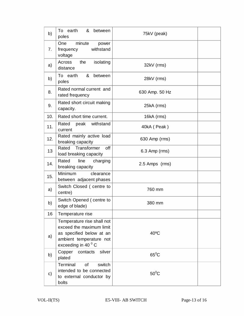
VOL-II(TS) E5-VIII- AB SWITCH Page-13 of 16
b) To earth & between poles 75kV (peak)
7. One minute power frequency withstand voltage
a) Across the isolating distance 32kV (rms)
b) To earth & between poles 28kV (rms)
8. Rated normal current and rated frequency 630 Amp. 50 Hz
9. Rated short circuit making capacity. 25kA (rms)
10. Rated short time current. 16kA (rms)
11. Rated peak withstand current 40kA ( Peak )
12. Rated mainly active load breaking capacity 630 Amp (rms)
13 Rated Transformer off load breaking capacity 6.3 Amp (rms)
14. Rated line charging breaking capacity 2.5 Amps (rms)
15. Minimum clearance between adjacent phases
a) Switch Closed ( centre to centre)
760 mm
b) Switch Opened ( centre to edge of blade)
380 mm
16 Temperature rise
a)
Temperature rise shall not exceed the maximum limit as specified below at an ambient temperature not exceeding in 40 0 C
40ºC
b) Copper contacts silver plated 650C
c)
Terminal of switch intended to be connected to external conductor by bolts
500C
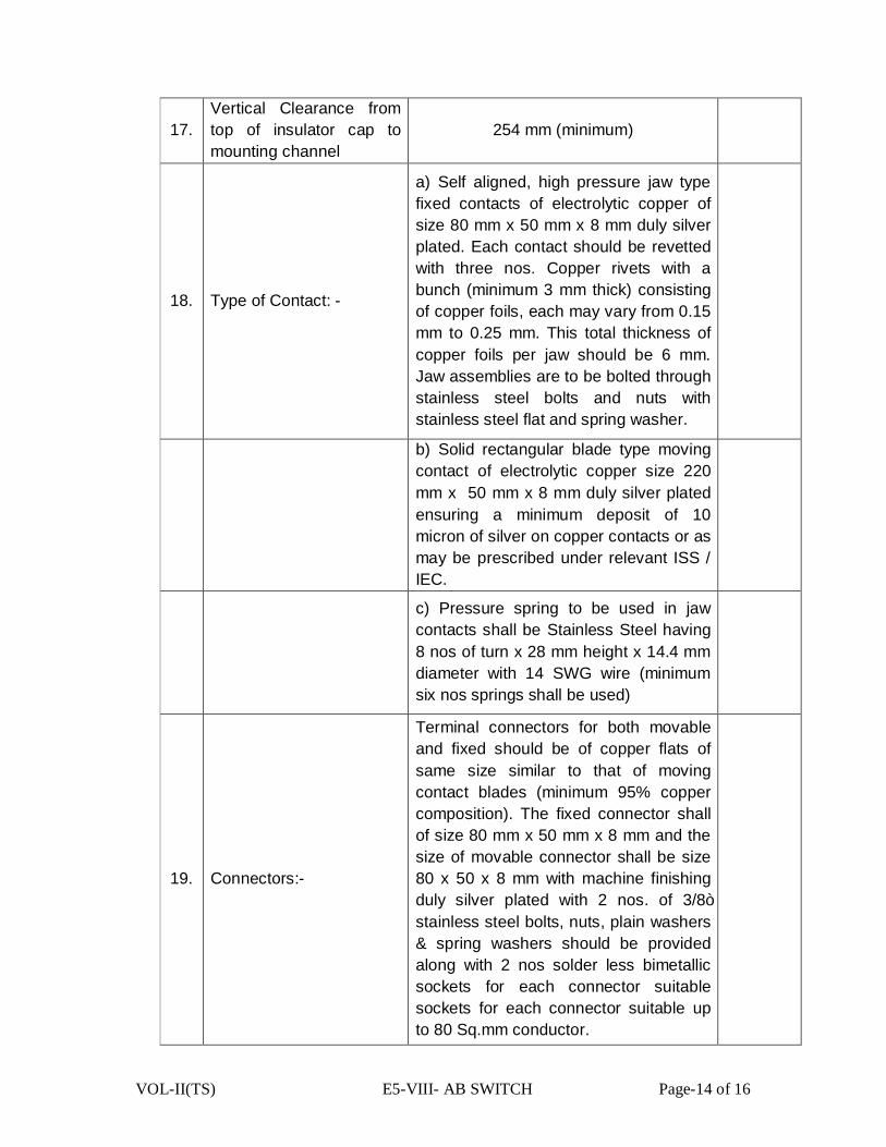
VOL-II(TS) E5-VIII- AB SWITCH Page-14 of 16
17. Vertical Clearance from top of insulator cap to mounting channel
254 mm (minimum)
18. Type of Contact: -
a) Self aligned, high pressure jaw type fixed contacts of electrolytic copper of size 80 mm x 50 mm x 8 mm duly silver plated. Each contact should be revetted with three nos. Copper rivets with a bunch (minimum 3 mm thick) consisting of copper foils, each may vary from 0.15 mm to 0.25 mm. This total thickness of copper foils per jaw should be 6 mm. Jaw assemblies are to be bolted through stainless steel bolts and nuts with stainless steel flat and spring washer.
b) Solid rectangular blade type moving contact of electrolytic copper size 220 mm x 50 mm x 8 mm duly silver plated ensuring a minimum deposit of 10 micron of silver on copper contacts or as may be prescribed under relevant ISS / IEC.
c) Pressure spring to be used in jaw contacts shall be Stainless Steel having 8 nos of turn x 28 mm height x 14.4 mm diameter with 14 SWG wire (minimum six nos springs shall be used)
19. Connectors:-
Terminal connectors for both movable and fixed should be of copper flats of same size similar to that of moving contact blades (minimum 95% copper composition). The fixed connector shall of size 80 mm x 50 mm x 8 mm and the size of movable connector shall be size 80 x 50 x 8 mm with machine finishing duly silver plated with 2 nos. of 3/8” stainless steel bolts, nuts, plain washers & spring washers should be provided along with 2 nos solder less bimetallic sockets for each connector suitable sockets for each connector suitable up to 80 Sq.mm conductor.
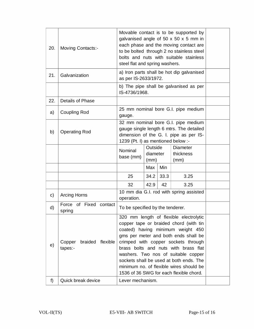
VOL-II(TS) E5-VIII- AB SWITCH Page-15 of 16
20. Moving Contacts:-
Movable contact is to be supported by galvanised angle of 50 x 50 x 5 mm in each phase and the moving contact are to be bolted through 2 no stainless steel bolts and nuts with suitable stainless steel flat and spring washers.
21. Galvanization a) Iron parts shall be hot dip galvanised as per IS-2633/1972.
b) The pipe shall be galvanised as per IS-4736/1968.
22. Details of Phase
a) Coupling Rod 25 mm nominal bore G.I. pipe medium gauge.
b) Operating Rod
32 mm nominal bore G.I. pipe medium gauge single length 6 mtrs. The detailed dimension of the G. I. pipe as per IS-1239 (Pt. I) as mentioned below :-
Nominal base (mm)
Outside diameter (mm)
Diameter thickness (mm)
Max Min
25 34.2 33.3 3.25
32 42.9 42 3.25
c) Arcing Horns 10 mm dia G.I. rod with spring assisted operation.
d) Force of Fixed contact spring To be specified by the tenderer.
e) Copper braided flexible tapes:-
320 mm length of flexible electrolytic copper tape or braided chord (with tin coated) having minimum weight 450 gms per meter and both ends shall be crimped with copper sockets through brass bolts and nuts with brass flat washers. Two nos of suitable copper sockets shall be used at both ends. The minimum no. of flexible wires should be 1536 of 36 SWG for each flexible chord.
f) Quick break device Lever mechanism.
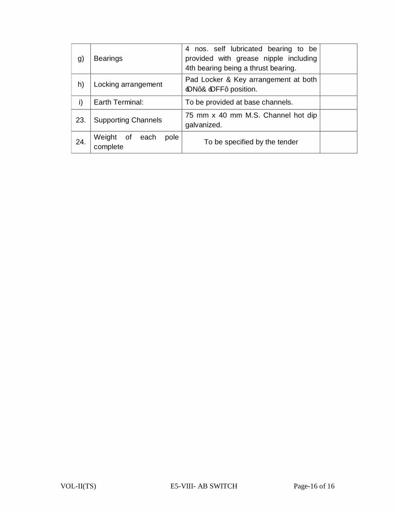
VOL-II(TS) E5-VIII- AB SWITCH Page-16 of 16
g) Bearings 4 nos. self lubricated bearing to be provided with grease nipple including 4th bearing being a thrust bearing.
h) Locking arrangement Pad Locker & Key arrangement at both ‘ON’ & ‘OFF’ position.
i) Earth Terminal: To be provided at base channels.
23. Supporting Channels 75 mm x 40 mm M.S. Channel hot dip galvanized.
24. Weight of each pole complete To be specified by the tender

VOL-II(TS) E7-V-SURGE ARRESTER Page 1 of 17
TECHNICAL SPECIFICATION
FOR
SURGE ARRESTERS
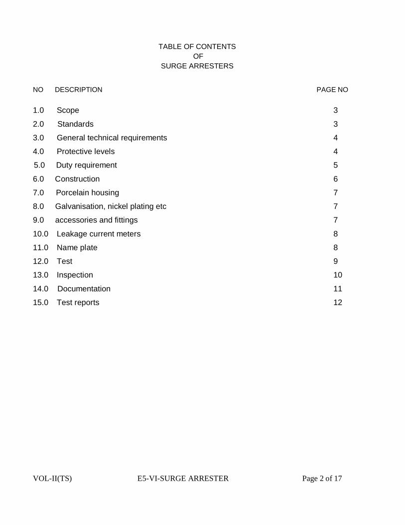
VOL-II(TS) E5-VI-SURGE ARRESTER Page 2 of 17
TABLE OF CONTENTS
OF SURGE ARRESTERS
NO DESCRIPTION PAGE NO 1.0 Scope 3
2.0 Standards 3
3.0 General technical requirements 4
4.0 Protective levels 4
5.0 Duty requirement 5
6.0 Construction 6
7.0 Porcelain housing 7
8.0 Galvanisation, nickel plating etc 7
9.0 accessories and fittings 7
10.0 Leakage current meters 8
11.0 Name plate 8
12.0 Test 9
13.0 Inspection 10
14.0 Documentation 11
15.0 Test reports 12

VOL-II(TS) E5-VI-SURGE ARRESTER Page 3 of 17
SURGE ARRESTERS TECHNICAL SPECIFICATION FOR SURGE ARRESTERS
1.0 SCOPE
This Specification provides for the design, manufacture, inspection and testing before dispatch, packing and delivery F.O.R. (destination) of Metal Oxide (gapless) Surge Arresters with discharge counters, insulating base, terminal connectors and other accessories as specified here in.
Following is the list of documents constituting this Specification. :
(i) Technical Specification (TS)
(ii) Check-List. Annexure-B
(iii) Calibration Status of testing equipments and meters/ Instruments.
Annexure-C
(iv) Check-list towards Type Test Reports. Annexure-D Note : Annexure-B,C,& D are to be filled up by the Bidder.
All the above along with amendments thereof shall be read and interpreted together. However, in case of a contradiction between the Technical Specification and any other volume, the provisions of this volume will prevail.
The Surge Arrester shall conform in all respects to high standards of engineering, design, workmanship and latest revisions of relevant standards at the time of offer and purchaser shall have the power to reject any work or materials, which in his judgement is not in full accordance therewith.
2.0 STANDARDS:-
Except to the extent modified in the Specification, the Surge Arrester shall conform to the latest editions and amendments of the standards listed hereunder.
Sl. No. Standard
Ref. No.
Title.
1 IEC-99-4 Specification for Surge Arresters without gap for AC System.
2 IS:2147 Degree of protection, provided by enclosures for low voltage switchgear and control.
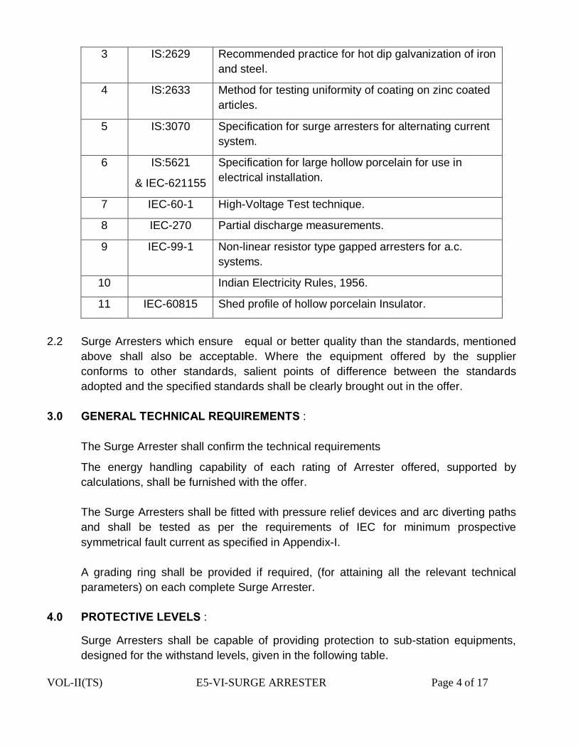
VOL-II(TS) E5-VI-SURGE ARRESTER Page 4 of 17
3 IS:2629 Recommended practice for hot dip galvanization of iron and steel.
4 IS:2633 Method for testing uniformity of coating on zinc coated articles.
5 IS:3070 Specification for surge arresters for alternating current system.
6 IS:5621
& IEC-621155
Specification for large hollow porcelain for use in electrical installation.
7 IEC-60-1 High-Voltage Test technique.
8 IEC-270 Partial discharge measurements.
9 IEC-99-1 Non-linear resistor type gapped arresters for a.c. systems.
10 Indian Electricity Rules, 1956.
11 IEC-60815 Shed profile of hollow porcelain Insulator.
2.2 Surge Arresters which ensure equal or better quality than the standards, mentioned above shall also be acceptable. Where the equipment offered by the supplier conforms to other standards, salient points of difference between the standards adopted and the specified standards shall be clearly brought out in the offer.
3.0 GENERAL TECHNICAL REQUIREMENTS : The Surge Arrester shall confirm the technical requirements
The energy handling capability of each rating of Arrester offered, supported by calculations, shall be furnished with the offer.
The Surge Arresters shall be fitted with pressure relief devices and arc diverting paths
and shall be tested as per the requirements of IEC for minimum prospective symmetrical fault current as specified in Appendix-I.
A grading ring shall be provided if required, (for attaining all the relevant technical
parameters) on each complete Surge Arrester. 4.0 PROTECTIVE LEVELS :
Surge Arresters shall be capable of providing protection to sub-station equipments, designed for the withstand levels, given in the following table.
VOL-II(TS) E5-VI-SURGE ARRESTER Page 5 of 17
Sl. No.
Equipment to be protected Insulation Level of 36KV System
Insulation Level of 12KV System
BIL (kVpeak) BIL (kVpeak) 1 Power Transformers. 170 78 2 Instrument Transformers. 170 78 3 Reactors 170 78 4 Circuit Breakers/Isolators. (i) Phase to ground. 170 78
Surge arrester shall be suitable for the following duty cycles of circuit breaker at the following system voltages:
36 kV Circuit Breaker O-0.3 sec-CO-3 min-CO 12 kV Circuit Breaker O-0.3 sec-CO-3 min-CO
5.0 DUTY REQUIREMENT : Surge Arresters shall be of heavy-duty station class and gapless type without any
series or shunt gaps.
i. Surge Arresters shall be capable of discharging over voltages occurring during switching of un-loaded transformers, lines, capacitors and reactors.
ii. The Surge Arresters shall be capable of discharging lightning and switching surges and temporary power frequency over-voltages.
iii. The Surge Arresters shall be capable of discharging the energy equivalent to class 3 of IEC-99-4.
The reference current of the arrester shall be high enough to eliminate the influence of grading and stray capacitance on the measured reference voltage. The supplier shall submit values and the supporting evidence along with calculations on above. Surge Arresters shall be fully stabilized thermally to give a life expectancy as per standard under site conditions. Surge Arresters shall be able to withstand maximum wind load of 260 Kg./sq.m. Surge Arresters shall be capable of withstanding effects of direct solar radiation.Surge arresters shall be capable of spark over on severe switching Surges and multiple strokes.
The Surge Arrester should be adequately designed to operate satisfactorily under temporary power frequency over-voltage as given in specific technical requirements, after discharging two shots of respective long duration surges.
VOL-II(TS) E5-VI-SURGE ARRESTER Page 6 of 17
Unless otherwise brought out separately by the Bidder in the schedule of deviations, the Surge Arresters, offered shall conform to the specification scrupulously. All deviations from the specification shall be brought out in the schedule of deviations. The discrepancies between the specification and the catalogues or literature, submitted as part of the offer shall not be considered as valid deviations unless specifically brought out in the schedule of deviations.
6.0 CONSTRUCTION :
Non linear blocks shall be sintered metal oxide material. These shall be provided in such a way as to obtain robust construction with excellent electrical and mechanical properties even after repeated operations.All the units of arresters of same rating shall be inter-changeable without adversely affecting the performance.The Surge Arresters shall be suitable for pedestal type mounting.All the necessary flanges, bolts, nuts, clamps etc. required for assembly of complete arrester with accessories and mounting on support structure to be supplied by the Contractor.The drilling details for mounting the Arrester on OPTCL/DISTCOM’s support shall be supplied by the OPTCL/DISTCOM. The minimum permissible separation between the Surge Arrester and any earthed object shall be indicated by the Bidder in his offer.Surge Arresters shall be designed to incorporate pressure relief devices and arc diverting paths to prevent shattering of the blocks or the porcelain housing, following prolonged current flow or internal flash over and providing path for flow of rated fault currents in the event of arrester failure.Surge Arresters shall incorporate anti-contamination feature to prevent arrester failure, caused by uneven voltage gradient across the stack, resulting from contamination of the arrester porcelain.Seals shall be provided in such a way that these are always effectively maintained even when discharging rated lightning current. The heat treatment cycle details along with necessary quality checks used for individual blocks along with insulation layer, formed across each block are to be furnished. Metalised coating thickness for reduced resistance between adjacent discs is to be furnished along with the procedure for checking the same. Details of thermal stability test for current distribution of current on individual disc is to be furnished. Each individual unit of Surge Arresters shall be hermetically sealed and fully protected against ingress of moisture. The hermetic seal shall be effective for the entire lifetime of the arrester and under the service conditions as specified. The supplier shall furnish sectional view of the arrester showing details of sealing employed.The Surge Arresters shall be suitable for hot line washing.
VOL-II(TS) E5-VI-SURGE ARRESTER Page 7 of 17
7.0 PORCELAIN HOUSING : All porcelain Housings shall be free from lamination cavities or other flaws, affecting the maximum level of mechanical and electrical strengths.The porcelain shall be well vitrified and non-porous.The minimum creepage distance of the arrester housing shall be as per Cl 7.21 of the TS. The porcelain petticoat shall be preferably of self-cleaning type (Aerofoil design). The details of the porcelain housing such as height, angle of inclination, shape of petticoats, gap between the petticoats, diameter (ID and OD) etc. shall be indicated by the Bidder in his offer in the form of detailed drawing.Porcelain housings shall be so co-coordinated that external flash over will not occur due to application of impulse or switching Surge voltages up to the maximum design value for arrester.
8.0 GALVANISATION, NICKEL PLATING ETC.
All ferrous parts exposed to atmosphere shall be hot dip galvanized as per IS: 2629, as amended from time to time. Tinned copper/brass lugs shall be used for internal wiring of discharge counter. Screws used for electrical connections shall be either made of brass or shall be nickel-plated.Ground terminal pads and nameplate brackets shall be hot dip galvanized.The material shall be galvanized only after completing all shop operations
9.0 ACCESSORIES AND FITTINGS 9.1 Surge Counters A self- contained Surge counter, suitably enclosed for outdoor use and requiring no
auxiliary of battery supply for operation shall be provided for each unit. The surge counter shall be operated by the discharge current, passed by the surge arrester and shall be suitable for mounting on the support structure of the Arrester.
Surge counters shall be of the Electro-mechanical type and designed for continuous
service. The cyclometer counter shall be visible through an inspection window from ground level. The counter terminals shall be robust and adequate size and shall be so located that the incoming and outgoing connections are made with minimum possible bends. Internal parts shall be unaffected by atmospheric conditions at site. Alternatively, a weather proof housing to IP 55 shall be provided and this shall be designed to allow the recording device to be read from ground level without exposing the internal parts to the atmosphere.
The Surge Counter shall be connected in the main earth lead from the arrester in such
a manner that the direction of the earth lead is not changed or its surge impedance materially altered. A bolted link shall be provided so that the surge counter may be short circuited and removed without taking the arrester out of service. All necessary
VOL-II(TS) E5-VI-SURGE ARRESTER Page 8 of 17
accessories and earthing connection leads between the bottom of the Arrester and discharge counter shall be in the Contractor’s scope of supply.
10.0 LEAKAGE CURRENT METERS : ( In case of 33 kV Surge Arrester only) Leakage current meters (suitable milli-ammeter) shall be connected in the earthing
path of the surge arresters to measure the resistor grading leakage current. Meters shall be designed for continuous service.
The ammeter shall be suitable for mounting on the support structure of the arrester.
The push buttons shall be mounted such that it can be operated from the ground level. The internal parts shall be fully weather - proof to IP 55 or better with a transparent
cover to provide an unobstructed view of the ammeter. Arresters shall be complete with insulating base having provision for bolting to flat surface of the structure.The grounding terminals shall be suitable for accommodating grounding connection to steel earth mat.
Clamp type terminal connector, suitable for AAAC conductor of 150 & 100 Sq mm
shall be provided having both horizontal and vertical take-off. Two clamp type ground terminal connectors, suitable for G. I. Strip (50 x 6) should be provided.All interconnecting hardwares such as nuts, bolts, spring washers etc. with 5% spares shall be supplied for different units.Pollution Shunt (Copper braid) shall be supplied along with each Surge Arrester for by-passing the surface current.Other standard accessories, which are specifically not mentioned, but are usually provided with Surge Arrester of such type and rating for efficient and trouble free operation should be supplied.
11.0 NAME PLATE : Each single pole Arrester shall be provided with non-corrosive legible name plate, at
the base bearing thereon, voltage rating of the complete pole and the number of demountable sections with the following data, indelibly marked
(a) Name of the DISTCOM (b) Purchase order No. & Date. (c) Name of device. (d) Manufacturer’s name and trademark and identification no. of the arrester being
supplied. (e) Year of manufacture (f) Rated voltage (g) Rated Frequency (h) Maximum continuous operating voltage. (i) Type
VOL-II(TS) E5-VI-SURGE ARRESTER Page 9 of 17
(j) Nominal discharge current. (k) Long duration discharge class. (l) Pressure relief current in KA(rms) (m) Energy discharge capability ( KJ / KV rating).
12.0 TEST : 12.1 Type Tests: The surge Arrester offered should have been subjected to the following Type tests in
an independent Government approved test laboratory. The bidder shall furnish four sets of type test reports along with the drawings for approval. These tests must not have been conducted earlier than five years from the date of opening of technical bid. For any change in the design type, already type tested and the design type offered against this specification, the purchaser reserves the right to demand repetition of some or all type tests without any extra cost and in presence of Purchaser’s representative at the cost of the Contractor.
1 Insulation withstands tests : (a) Lightning Impulse Voltage Test. 2 Residual voltage tests. 3 Long duration current impulse withstand tests. 4 Operating duty tests. 5 Pressure relief tests. (a) High current test. (b) Low current test. 6 Power frequency voltage vs. time curve. (Temporary over voltage test) 7 Contamination test. (artificial pollution test). 8 Seismic withstand test. 9 IP-55 test on surge counter. 10 Minimum current operation tests of the surge counter. 11 Maximum current withstand test of the surge counter. 12 Mechanical terminal load test on bushing. 13 Partial discharge test. N.B. :-Even if the condition i.e. the dry arcing distance or the sum of the partial dry arcing
distances is larger than the test voltage divided by 500 KV/m’, the lightning impulse voltage test must have been conducted or is to be conducted without any financial liability to OPTCL.
VOL-II(TS) E5-VI-SURGE ARRESTER Page 10 of 17
12.2 ROUTINE TESTS :
The following Routine tests shall be conducted at the supplier’s cost on each Surge Arrester and shall be submitted along with or before offering for inspection for purchaser’s approval.
(a) Measurement of reference voltage. (b) Residual voltage tests. (c) Measurement for partial discharge and contact noise. (d) Sealing test for units with sealed housings. 12.3 ACCEPTANCE TESTS : The following tests, considered as Acceptance tests, shall be conducted in the
presence of purchasers representative for which no charges will be payable by purchaser. The acceptance tests, whenever possible shall be conducted on the complete arrester unit. The number of samples to be subjected to acceptance test shall be decided by the purchaser at the time of actual testing.
I Temperature Cycle Test on Housing. II Measurement of Power Frequency Voltage at the reference current. III Measurement of leakage current and capacitive current at M.C.O.V. IV Lightning Impulse Residual Voltage Test at N.D.C., 50% of N.D.C. & 200% of N.D.C. V Partial Discharge Tests on complete arresters/units at 1.05 times M.C.O.V. VI Special Thermal stability test. VII Porosity test on porcelain components. VIII Galvanization test on metal parts. IX The functional (operational) test on the Surge Counter by way of checking its
operation at following nominal discharge currents :
a) 100 Amps with 8/20 micro second wave shape. b) 10 KA with 8/20 micro second wave shape.
X Check of calibration of leakage current meters. 13.0 INSPECTION : I The purchaser shall have access at all time to the works and all other places of
manufacture, where the Surge Arresters are being manufactured and the supplier shall provide all facilities for unrestricted inspection of the supplier’s works, raw materials, manufacture of all the accessories and for conducting the necessary tests.
VOL-II(TS) E5-VI-SURGE ARRESTER Page 11 of 17
II The supplier shall keep the purchaser informed in advance of the time of starting and the progress of manufacture of equipment in its various stages so that arrangements could be made for inspection.
III No material shall be despatched from its point of manufacture unless the material has been satisfactorily inspected, tested and despatch schedule attached to this specification.
IV The acceptance of any quantity of equipment shall in no way relieve the supplier of his responsibility for meeting all the requirements of this specification and shall not prevent subsequent rejection, if such equipments are later found to be defective.
14.0 DOCUMENTATION : All drawings shall conform to relevant Indian Standard as per relevant IS. All drawings
shall be in ink and suitable for microfilming. All dimensions and data shall be in S.I. Units. The supplier shall furnish two sets of following drawings / documents along with his offer.
(i) General outline drawings of the complete Arrester with technical parameters. (ii) Drawings showing clearance from grounded and other line objects and between
adjacent poles of Surge Arresters, required at various heights of Surge Arresters. (iii) Drawings showing details of pressure relief devices. (iv) Detailed drawing of discharge counters along with the wiring and schematic drawing of
discharge counter and meter. (v) Outline drawing of insulating base. (vi) Details of grading rings, if used. (vii) Mounting details of Surge Arresters. (viii) Details of line terminal and ground terminals. (ix) Volt-time characteristics of Surge Arresters. (x) Details of galvanization being provided on different ferrous parts. (xi) The detailed dimensional drawing of porcelain Housing such as ID, OD, thickness and
insulator details such as height, profile of petticoats, angle of inclination and gap between successive petticoats, total creepage distance etc.
(xii) Cross-sectional view of the Surge Arrester Units showing all components.
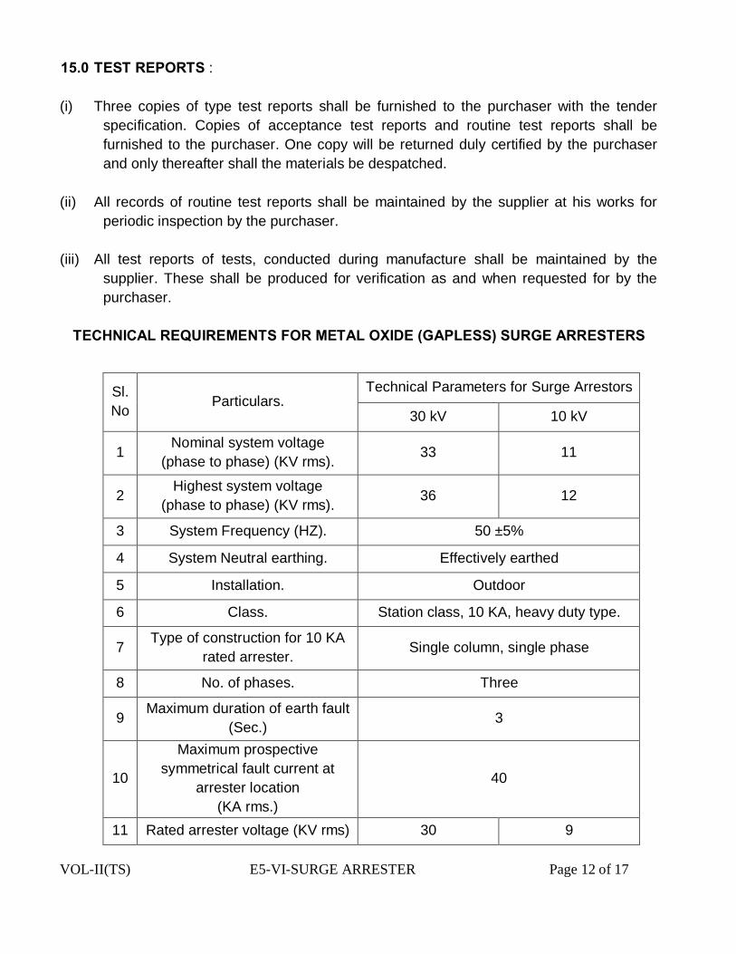
VOL-II(TS) E5-VI-SURGE ARRESTER Page 12 of 17
15.0 TEST REPORTS : (i) Three copies of type test reports shall be furnished to the purchaser with the tender
specification. Copies of acceptance test reports and routine test reports shall be furnished to the purchaser. One copy will be returned duly certified by the purchaser and only thereafter shall the materials be despatched.
(ii) All records of routine test reports shall be maintained by the supplier at his works for
periodic inspection by the purchaser. (iii) All test reports of tests, conducted during manufacture shall be maintained by the
supplier. These shall be produced for verification as and when requested for by the purchaser.
TECHNICAL REQUIREMENTS FOR METAL OXIDE (GAPLESS) SURGE ARRESTERS
Sl. No Particulars.
Technical Parameters for Surge Arrestors
30 kV 10 kV
1 Nominal system voltage (phase to phase) (KV rms). 33 11
2 Highest system voltage (phase to phase) (KV rms). 36 12
3 System Frequency (HZ). 50 ±5%
4 System Neutral earthing. Effectively earthed
5 Installation. Outdoor
6 Class. Station class, 10 KA, heavy duty type.
7 Type of construction for 10 KA rated arrester. Single column, single phase
8 No. of phases. Three
9 Maximum duration of earth fault (Sec.) 3
10
Maximum prospective symmetrical fault current at
arrester location (KA rms.)
40
11 Rated arrester voltage (KV rms) 30 9
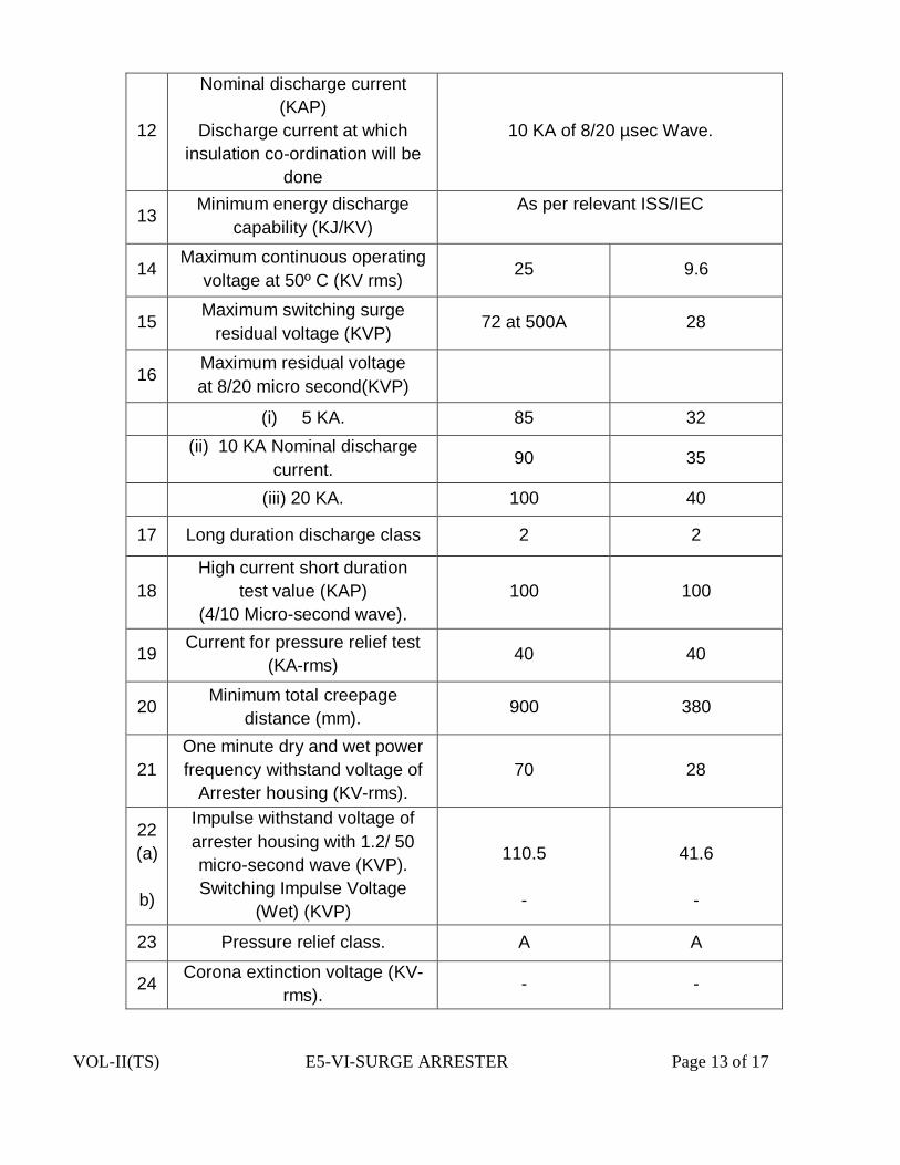
VOL-II(TS) E5-VI-SURGE ARRESTER Page 13 of 17
12
Nominal discharge current (KAP)
Discharge current at which insulation co-ordination will be
done
10 KA of 8/20 µsec Wave.
13 Minimum energy discharge
capability (KJ/KV) As per relevant ISS/IEC
14 Maximum continuous operating
voltage at 50º C (KV rms) 25 9.6
15 Maximum switching surge
residual voltage (KVP) 72 at 500A 28
16 Maximum residual voltage at 8/20 micro second(KVP)
(i) 5 KA. 85 32
(ii) 10 KA Nominal discharge current.
90 35
(iii) 20 KA. 100 40
17 Long duration discharge class 2 2
18 High current short duration
test value (KAP) (4/10 Micro-second wave).
100 100
19 Current for pressure relief test (KA-rms) 40 40
20 Minimum total creepage distance (mm). 900 380
21 One minute dry and wet power frequency withstand voltage of
Arrester housing (KV-rms). 70 28
22 (a)
b)
Impulse withstand voltage of arrester housing with 1.2/ 50 micro-second wave (KVP). Switching Impulse Voltage
(Wet) (KVP)
110.5
-
41.6
-
23 Pressure relief class. A A
24 Corona extinction voltage (KV-rms). - -

VOL-II(TS) E5-VI-SURGE ARRESTER Page 14 of 17
25 RIV at 92 KV rms. Less than 500 micro volts
Less than 500 micro volts
26 Partial discharge at 1.05 times continuous over-voltage.
Nor more than 50 PC
Nor more than 50 PC
27 Seismic acceleration. 0.3g horizontal 0.15g vertical
0.3g horizontal 0.15g vertical
28
Reference ambient temperature. 50ºC 50ºC
29 (a) IR at MCOV. Less than 400 micro amperes
Less than 400 micro amperes
(b) IC at MCOV.
Less than 1200 micro amperes
Less than 1200 micro amperes
30 a) Reference Current (mA) 1 to 5 mA
b) Reference voltage at
reference current. Greater than rated voltage.
31 Maximum steep current Impulse RDV (KVP). at KAP 100
32 Maximum cantilever strength of the arresters (KGM). 325 325
33 TOV(KVP).
(i) 0.1 sec. 53 20
(ii) 1.0 sec. 51 18
(iii) 10.0 sec. 49 16
(iv) 100.0 sec. 47 14

VOL-II(TS) E5-VI-SURGE ARRESTER Page 15 of 17
ANNEXURE – B
CHECK – LIST 1 Whether calculation towards energy handling capability of the Surge Arrester furnished? 2 Whether the heat treatment cycle details along with necessary quality checks used for
individual blocks furnished ? 3 Whether sectional view of arrester furnished showing details of sealing provided? 4 Whether porcelain petticoat is of Aero foil design? Whether drawing of porcelain
Housing as per Clause No.7.9 of TS furnished? 5 Whether drawings and documents as per TS furnished? 6 Whether special measures in the manufacture of Surge Arrester for operating at
ambient temperature of 50ºC (against 40 ºC as per IEC-99-4, Clause No.4.4.1) are to be taken? ………………….. State the special measures in details ………………….
Signature of the Tenderer With Seal & Date
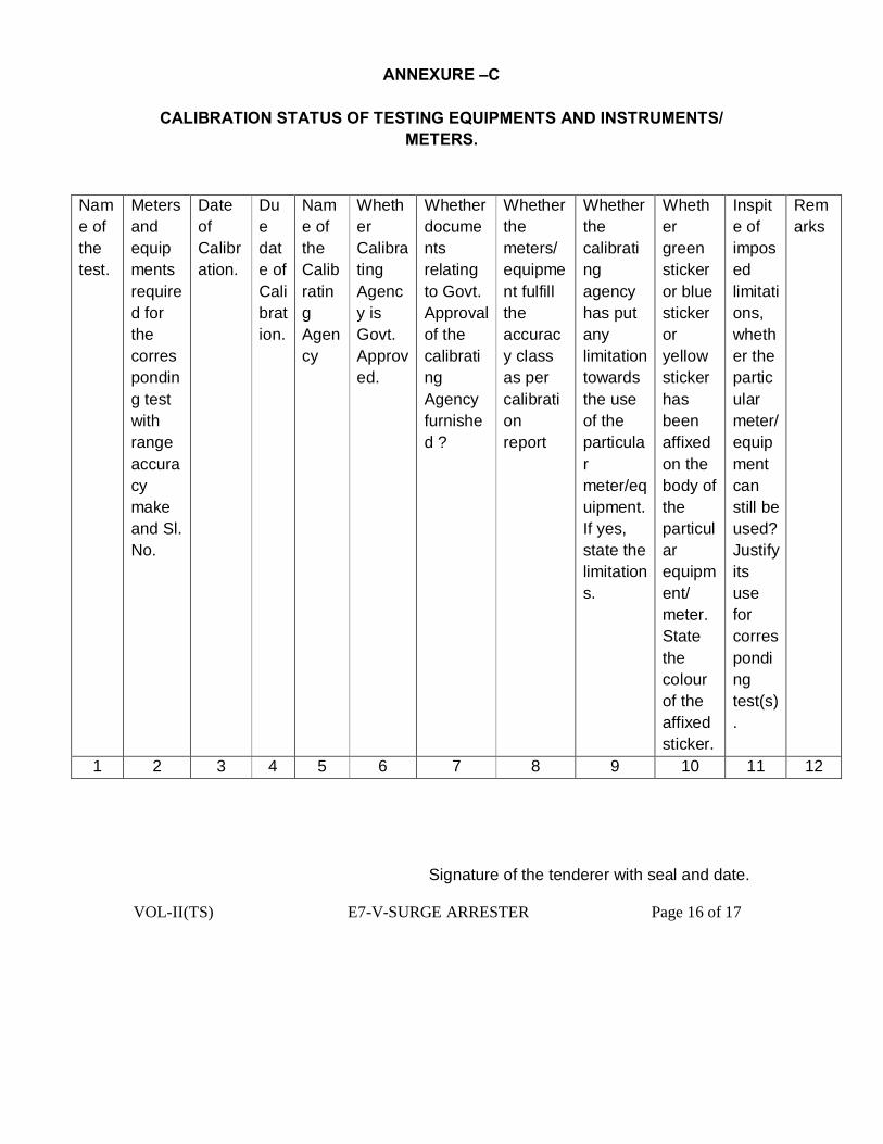
VOL-II(TS) E7-V-SURGE ARRESTER Page 16 of 17
ANNEXURE –C
CALIBRATION STATUS OF TESTING EQUIPMENTS AND INSTRUMENTS/ METERS.
Name of the test.
Meters and equipments required for the corresponding test with range accuracy make and Sl. No.
Date of Calibration.
Due date of Calibration.
Name of the Calibrating Agency
Whether Calibrating Agency is Govt. Approved.
Whether documents relating to Govt. Approval of the calibrating Agency furnished ?
Whether the meters/ equipment fulfill the accuracy class as per calibration report
Whether the calibrating agency has put any limitation towards the use of the particular meter/equipment. If yes, state the limitations.
Whether green sticker or blue sticker or yellow sticker has been affixed on the body of the particular equipment/ meter. State the colour of the affixed sticker.
Inspite of imposed limitations, whether the particular meter/equipment can still be used? Justify its use for corresponding test(s).
Remarks
1 2 3 4 5 6 7 8 9 10 11 12
Signature of the tenderer with seal and date.
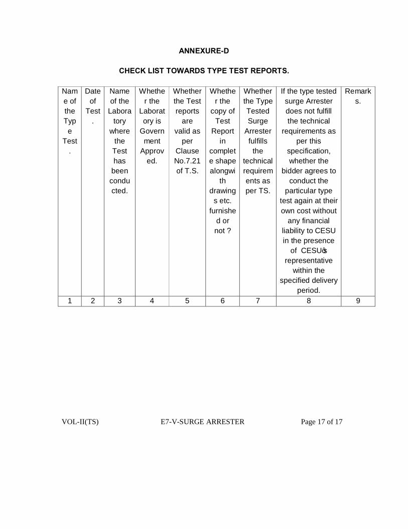
VOL-II(TS) E7-V-SURGE ARRESTER Page 17 of 17
ANNEXURE-D
CHECK LIST TOWARDS TYPE TEST REPORTS. Name of the Type
Test.
Date of
Test.
Name of the
Laboratory
where the Test has
been conducted.
Whether the
Laboratory is
Government
Approved.
Whether the Test reports
are valid as
per Clause No.7.21 of T.S.
Whether the
copy of Test
Report in
complete shape alongwi
th drawing
s etc. furnishe
d or not ?
Whether the Type Tested Surge
Arrester fulfills the
technical requirements as per TS.
If the type tested surge Arrester does not fulfill the technical
requirements as per this
specification, whether the
bidder agrees to conduct the
particular type test again at their own cost without
any financial liability to CESU in the presence
of CESU’s representative
within the specified delivery
period.
Remarks.
1 2 3 4 5 6 7 8 9


![DADOS TÉCNICOS VIRIATO.COM.PT [01.08] TECHNICAL SPEC ... · divisora divider diviseuse divisora teigteilmaschine dados tÉcnicos technical spec. datos tÉcnicos donnÉes techniques](https://static.fdocuments.us/doc/165x107/5e2491ac7c73ba749723b3f8/dados-tcnicos-0108-technical-spec-divisora-divider-diviseuse-divisora-teigteilmaschine.jpg)