Technical Sheet and Installation Guide Autoclaved … Hebel Aerated Concrete 1 Technical Sheet 1.1...
12
Autoclaved Aerated Concrete Technical Sheet and Installation Guide
Transcript of Technical Sheet and Installation Guide Autoclaved … Hebel Aerated Concrete 1 Technical Sheet 1.1...

Autoclaved Aerated Concrete
Technical Sheetand Installation Guide

2 Hebel Aerated Concrete
1 Technical Sheet1.1 Hebel Slab Panel
General FeaturesHebel Autoclaved Aerated Concrete (AAC) Floor and Roof Slab Panels are lightweight, fire resistant, fast and easy to install and provide lifelong superior thermal insulation. Hebel Slab Panels are steel reinforced (Grade 70) Autoclaved Aerated Concrete elements. The interior steel wire reinforcement is covered with an anti-corrosion coating. Hebel Slab Panel is produced in an ASTM C 1452 strength class: AAC-6.
UsesHebel Slab Panels are used as floor and roof simply-supported slabs on Hebel Masonry Components or CMU load-bearing walls, wood, concrete or steel beams. These panels are used in residential, multi-family housing, hotels, offices and industrial buildings. Hebel AAC meets the diverse demands better than any other material due to the numerous advantages of its physical, mechanical, energy efficiency and safety properties.
Class:
Dimensions
Up to 20 ft
24 in.
4, 5, 6, 7, 8, 10 and 12 in.
AAC-6
Length: (2)
Width:
Nominal Thickness: (1)(3)
Thermal Conductivity
Unit: BTU = british thermal unit , in = inches, ft = foot, h = hour, °F = fahrenheit
Thermal ConductivitySteady-State
Class
AAC-6
0.9811 BTU-in/ft2-h-0F
Table 2: Hebel Slab Panel thermal conductivity.
Table 1: Physical and design properties.
Characteristic Unit
0.02
8 x 10⁻⁶
Compressive Strength (f’aac)
Nominal Density
Design Weight
Drying Shrinkage
Thermal Expansion Coefficient
Thermal Conductivity
Water Vapor Permeability
Modulus of Elasticity
Modulus of Rupture (MOR)
Allowable Bearnig Stress
PropertiesStrength Class
AAC-6psi
pcf
pcf
%
K-1
BTU-in/ft2h0F
ng/Pa.s.m
psi
psi
psi
870
37
45
0.9811
0.226
377,000
142
523
Fig. 1: Hebel Slab Panel.
Fire Performance
Reinforced Slab Panel AAC-6
Note: Testing performed at Underwriters Laboratories, Inc., Northbrook, IL under ASTM E119 (UL/ANSI 263) “Fire Tests of Building Construction and Materials”.
Hebel Slab Panel UL DesignNumber
1
4
Table 3: Hebel Slab Panel fire rating.
Fire Ratings(Hours)
K909P932
Thickness(Inch)
4
5>
Table 4: Allowable service loads for AAC Slab Panels.
6.68.29.8
11.513.114.816.418.020.0
149115653619------------
------15112610872473016
---
149127111956541
---
14812811310270
1548845------------------
------1561287949---------
---
155133986542---
---
---1541351067345
For superimposed loads over 150 psf contact Xella Texas.
For superimposed loads over 150 psf
contact Xella Texas.
AAC Roof Panels AAC Floor PanelsPanel Thickness [in] Panel Thickness [in]
4
14.8
6
22.1
7
25.8
8
29.5
4
14.8
6
22.1
7
25.8
8
29.5Selfweight [psf] Selfweight [psf]
Length[ft]
Maximum Allowable Service Load - Hebel Slab Panel AAC-6Uniform Load – [psf]
Note: Panel Class AAC-6 and 24 in width. Superimposed uniform loads were calculated in accordance to ACI-523 design methodology. All roof panels meet or exceed L/240 live load and L/180 total load vertical deflections at the allowable loads indicated. All floor panels meet or exceed L/360 live load and L/240 total load vertical deflations at the allowable loads indicated. Superimposed dead load of 12.2 psf (roof panels) or 30.7 psf (floor panels) and the compression reinforcement contribution for long term deflection were considered.(1) Tolerance + 1/8”, (2) Tolerance + 3/16”,
(3) Nominal. Manufactured according to ASTM C1452._ _

Hebel Aerated Concrete 3
OSHA trainer for “rigging” or other safety considerations. Insure adherence to Leading Edge Support OSHA Guidelines.
- Carefully unload panels using pallet forks (forklift, nylon straps, slings or pallet fork on a crane cable). Place pallets over wood blocks (panels must not be in contact with ground).
- Storage areas should be accessible to delivery trucks and convenient to staging areas. If possible, drop-deliver the material right to the material staging areas.
- Material should always be stored away from other construction activities on a flat-grade area that is not susceptible to standing water, erosion or settling.
2. Check material and installation logistic
- Verify dimensions, positions and quantity of the panels according to Hebel shop drawings.
- Define sequence of panel installation according to Hebel shop drawings. To help speed installation, place the panels with the groove side at the beginning and continue.
- Define type of installation equipment (crane or similar).
- Evaluate quantity of personnel required for installation ( 4 to 5 assistants for panel installation plus crane operator).
- Keep the material covered and banded until ready for installation. Excessive handling may cause damage. Set delivery schedule to match the erection sequence.
- Chips and spalls can be repaired. If any reinforcing is visible, contact an authorized AAC representative. All damaged
surface areas may be repaired using a compatible AAC patching compound.
- All panels that have surface or minor cracks are usable. Contact an authorized AAC representative when a crack is extended completely through the panel.
3. Check existing steel accessories (not supplied by Xella AAC Texas).
- Steel accessories for holes (ducts) -1 or 2 panels width- in floor and roofs.- Steel plate for connecting Slab Panels to steel structure.
4. Check support structure
- All support elements (load-bearing walls, concrete or steel beams, etc) must be already finished before receiving floor and roof panels.
- Check layout and top of supporting structure. AAC top block adjustments must not be less than 2” in height, or elsecement-sand mortar (1:4) must be used (see Fig. 12-A).
Fig. 2: Hebel Slab Panel Pallets.
Fig. 3: Panel identification.
Project Number
Panel positionPanel type / areaE: Floor panelA: Roof panel
91593 P02 A01
2 Design Considerations2.1 General Considerations
• Hebel Autoclaved Aerated Concrete (AAC) Slab Panels can be used as floor or roof systems and shall be designed in order to comply with strength and serviceability requirements as specified by ACI-523.4R-09
• The Slab Panel thickness and the span will determine the allowable service load (see Table 4). The load (dead and live) must comply with the Local and Regional Building Code.
• Floor and roof panels can be supported by AAC Masonry Walls, reinforced concrete, concrete masonry walls (CMU), wood or steel beams.
• AAC Slab Panels are reinforced with two layers of high strength smooth bars (Fy = 70,000 psi) which are protected with an anti-corrosive coat.
• The longitudinal bars develop their tensile stress using mechanical anchorage provided by cross bars .
3 Installation GuideBefore installation of Hebel Slab Panels
3.1 General Installation Guidelines
1. Clear the unloading and provisional storage area
- Consult an appropriate safety professional or knowledgeable

3.2 Installation Requirements
The actual list of tools, equipment and other materials will depend on type of project and workforce.
Tools:- Hammer-Ax.- Rubber Mallet.- Scrub Brush.- Hebel Sanding Float.- Hebel Plastic Bucket.- Chasing Tools.- Spatula.- Chalk-Line.- Tape Measure.- Finishing Trowels.- Ripping Bar (36”).
4 Hebel Aerated Concrete
- Bearing lengths for AAC floor and roof panels should comply with Table 5.
- Mark guidelines on top of the supporting elements according to bearing lengths in Hebel shop drawings.
- For non-load-bearing elements, put a layer of a compressible material (polystyrene or similar) on top.
Fig. 4: Storage area close to job site.
Fig. 5: Slab Panel supported by steel elements.
Precaution: Always wear proper personal protection equipment when using a circular saw, band saw or an angle grinder, including goggles, face-shield, hearing protection and dust mask.
Equipment:- Hebel Slab Panel Lifting Gear or Clamp (optional).- Telescopic Crane or similar.- Circular Saw (8¼” diam min)
with metal cutting blade orGasoline-Powered Circular Saws ( 12” min).
- ½” Power Drill / Stirrer.- Router / Bits.- Hebel Hand Saw- Hebel Turners (2 pc).- Safety Equipment (Hard hat,
face-shield, goggles, dust mask, ear plugs, gloves, safety shoes, etc.).
Other materials:- Hebel Thin Bed Mortar and Rapair Mortar.- Hebel Rebar Spacers.- Anticorrosive Paint.- Fiberglass Mesh- 4x4 in. Wood Block (2 ft long).- Rebar #3, #4- Cement-Sand Mortar.- Concrete (3.000 psi).- Steel Plates.- Hebel Stucco, Base-Coats, Textures, etc.- Anchors & Hebel Nails.
Note: Mayor equipment / tools are listed but not limited to items noted above to complete the installation.
Fig. 6: Panel lifting gear T800.
Fig. 7: Panel lifting gear T1400.
Minimum Bearing Length (in)
Ld/80 or 2¾” (min)
Ld/80 or 2.0” (min)
Ld/80 or 1.5” (min)
Support Elements
Hebel Masonry
Concrete orReinforced Concrete
Wood
Steel Beams
Note: Ld = Effective span length, Le = Clear span, where Ld = Le + 3 inches.
Table 5: Minimum bearing length for Slab Panels.
Ld/80 or 2.0” (min)

Hebel Aerated Concrete 5
3.3 Installation of Hebel Slab Panels
a. Identify Hebel Panels to be installed according to previous logistics (see section 3.1 (2) and Fig. 3).
b. Carefully unpack panels using scissors or a hammer ax. Verify that panels are in a stable position prior to cutting the banding.
c. Over 4x4” wood blocks, rotate Slab Panel 90° or until tongue and groove profiles are facing up. Mark center of panel -Panel length/2- (see Fig. 8).
d. Clean the tongue and groove surface using a sanding float, hammer and a brush.
e. Place lifting gear at center of panel (see Fig. 8).
IMPORTANT:• Handle panels with care to avoid damage.• Make chases needed prior to installation.• It is strictly forbidden at any time for people to be under the load during lifting.• Never put hands, arms, feet or legs between the jaws of the clamp.• The load must always be hoisted; it may not dragged along the ground.• Avoid sudden movement to prevent accidental release of the load.
Fig. 8
Fig. 10
Fig. 9
Fig. 11
f. Using the pulleys, close clamps, clipping the tongue and groove sides of the panel.
g. Fasten safety chains avoiding excessive tightening, lower the locking lever (unlock position) and indicate to crane operator to lift the panel (see Fig. 9).
h. Two people will lead the panel to place it on the support (masonry, steel beams, etc).
i. Remove safety chains (see Fig. 10).
j. Place the panel on the guidelines previously traced. Verify minimum bearing length (see Fig. 11).
k. Once the panel is placed, open the clamps, raise the locking lever (lock position) and remove the lifting gear.
l. This procedure should be followed for each successivepanel.
6 Hebel Aerated Concrete
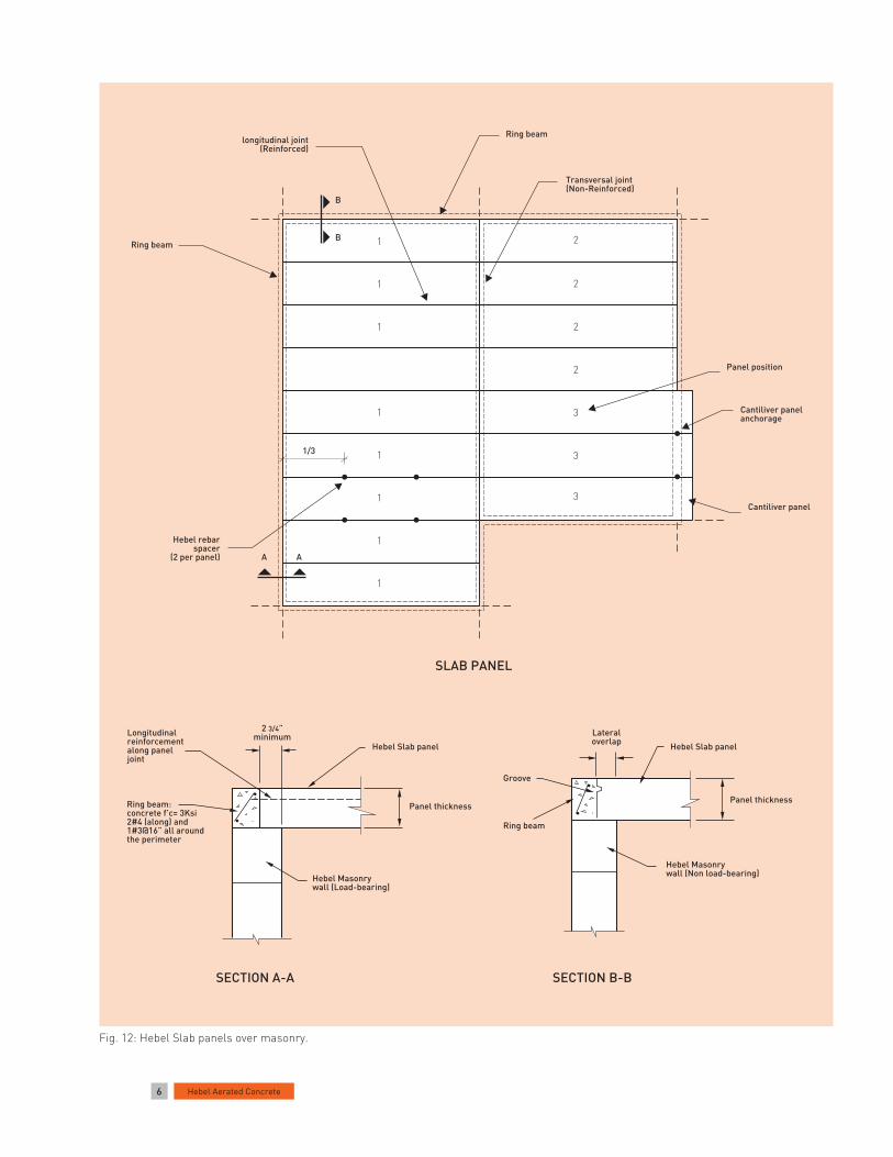
Fig. 12: Hebel Slab panels over masonry.
longitudinal joint(Reinforced)
B
B
Ring beam
Transversal joint(Non-Reinforced)
Ring beam
Panel position
Cantiliver panelanchorage
Cantiliver panel
1/3
Hebel rebarspacer
(2 per panel) A A
SLAB PANEL
2 3/4”minimum
Hebel Slab panel
Panel thickness
Hebel Masonrywall (Load-bearing)
Ring beam:concrete f’c= 3Ksi2#4 (along) and1#3@16” all aroundthe perimeter
Longitudinalreinforcementalong paneljoint
SECTION A-A SECTION B-B
Hebel Masonrywall (Non load-bearing)
Panel thickness
Hebel Slab panel
Lateraloverlap
Ring beam
Groove

7Hebel Aerated Concrete
3.4 Cast and Reinforcement of longitudinal joints and ring beams
After panel installation, place steel reinforcement in longitudinal joints (see Fig. 12 to 15 and 17) and ring beams surrounding panels (see Fig. 14 and 17). Forms must be placed in perimetral ring beams.
One #3 rebar is required in longitudinal joints (shear joints), wedged with rebar spacers (2 per panel), and filled with cement-sand mortar (1:4) - see Fig. 14. Moist Panel joints before application.
Ring beams require 2#4 rebars (along) and a #3 every 16” (diagonal) and filled with regular concrete f’c= 3 ksi. The maximum size of coarse aggregate is 3/8” and 5” to 6” of slump. Ring beam and form surfaces must be moist before concrete casting.
Fig. 15: Five-story hotel built with AAC (floor panels).
Fig. 13: Slab panel cross-section view.
Fig. 14: Longitudinal joint and ring beam.
Fig. 16: Conduit and ceiling fixtures.
Smooth finish
Cement-sand mortar (1:4)
1#3 Rebar Tonguejoint
Fiberglass meshReinforcement
Panelthickness
Groove joint
Hebel Slab panel
Ring beam(2#4 and #3@16”)concrete f’c= 3Ksi
Longitudinaljoint betweenpanels (1#3 andcement-sand mortar)
8”8”
6”
Masonry
Rebar Conduit
Slabpanel
Fiberglass meshCut usinga small anglegrinder
2 3/4” 2 3/4”
2 1/4”min.
RebarGalv. wire
Slabpanel
Ceiling outlet box
8 Hebel Aerated Concrete
Fig. 17
8 Hebel Aerated Concrete
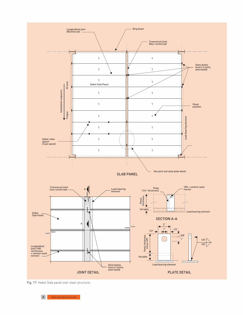
Fig. 17: Hebel Slab panel over steel structure.
SECTION A-A
Load bearing elementVariable
Pan
elth
ickn
ess
1#3 + cement-sandmortarPlate
(1/4” thickness)
PLATE DETAIL
Load bearing element
Variable
Pan
el th
ickn
ess
min
us 3
/8”
1/2”
2”
1”
5/8”
1/8”
1/8”
1”
1/2”
JOINT DETAIL
Transversal joint(non reinforced) A
A
Load-bearingelement
HebelSlab Panel
Longitudinaljoint (1#3continuous+ cement-sandmortar)
Steel plates(every 2 joints,alternated)
Transversal joint(Non reinforced)
Longitudinal joint(Reinforced)
Ring beam
Panelposition
Load
-bea
ring
ele
men
t
See joint and steel plate detail
Hebel rebarspacer(2 per panel)
Hebel Slab Panel
Steel plates(every 2 joints,alternated)
Gro
ove
Tong
ueInst
alla
tion
sequ
ence
SLAB PANEL
1
1
1
1
1
1
1
1
1
1
1
1
1
1
1
1
1
1
9Hebel Aerated Concrete
1/8”
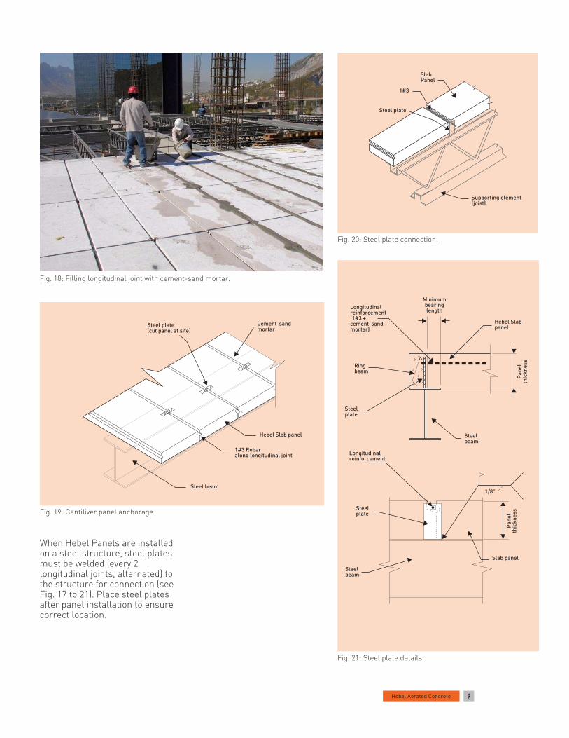
Fig. 18: Filling longitudinal joint with cement-sand mortar.
Fig. 20: Steel plate connection.
Fig. 19: Cantiliver panel anchorage.
Fig. 21: Steel plate details.
When Hebel Panels are installed on a steel structure, steel plates must be welded (every 2 longitudinal joints, alternated) to the structure for connection (see Fig. 17 to 21). Place steel plates after panel installation to ensure correct location.
SlabPanel
1#3
Steel plate
Supporting element(joist)
Cement-sandmortar
Steel plate(cut panel at site)
Hebel Slab panel
1#3 Rebaralong longitudinal joint
Steel beam
Steelbeam
Slab panel
Steelplate
Steelbeam
Steelplate
Ringbeam
Minimumbearinglength
Hebel Slabpanel
Longitudinalreinforcement(1#3 +cement-sandmortar)
Pan
elth
ickn
ess
Pan
elth
ickn
ess
Longitudinalreinforcement

10 Hebel Aerated Concrete
3.5 Utilities Installation
Openings
Openings in floor and roofs for A/C ducts, staircases, roof windows, air exhausters, etc. are built using steel support. For more information, please call Xella Technical Department.
Electrical conduits
Electrical conduits with a diameter < 1” can be lodged through longitudinal joints on top or bottom of the panels. For electrical conduits >1” or several electrical conduits, longitudinal joints can be widened to lodge them. It is not recommended to chase on top and across the panel width -transversal chase- (see Fig. 16).
It is possible to define cut surfaces in Panels regarding installations. For more information, please call Xella Technical Department.
Piping lines
When required, PVC and other piping lines can pass throughholes in the panels. The maximum hole diameter permitted in one panel is 6” or 12” in a joint between panels (6” each panel). If more than one hole is required, they must be aligned along the length of the panel. Only two longitudinalrebar in the bottom reinforcement of the panel can be cut (see Fig. 22and 24).
3.6 Panels Cutting
According to shop drawings, identify Hebel Slab Panels to be cut. Permissible cutting length is indicated on shop drawings, otherwise contact Xella Technical Department. Along its length, Hebel Slab Panel can be cut 1/3” the width.
Cutting equipment options
• Electric Circular Saw (8¼” blade diameter).
• Power Cutter (gasoline-powered) 12” blade or greater (see Fig. 23).
Cutting procedures
a. Prepare a flat surface for cutting site.
b. Check dimensions of cuts to be made.
c. For transversal cuts, wood pieces must be placed along the sides of the cut and at the edges of the panel.
Caution: Wear protective helmet& visor, goggles, hearing and
respiratory protection. Read equipment instruction manual. Inhalation of concrete dust above recommended exposure levels may be harmful. Wet sawing is recommended. Please consult the Xella Material Safety Data Sheet for further details.
d. For longitudinal cuts, wood pieces must be placed at every 6 ft. (max) for 6 to 12 in thick panels and every 4 ft for panels 4 to 5 in thick.
e. Check for full contact between wood pieces and panel. Wedge if necessary.
f. Place a ruler as a guide and trace the cut dimensions.
g. Proceed with panel cutting, verifying that cutting dimensions comply with specifications. Transversal and longitudinal cuts must be made with panel in horizontal position; if full thickness is to be cut, perform cut from both sides.
h. Apply anticorrosive paint atreinforced bar tips.
Fig. 22: Sanitary utilities.
Fig. 23: Power cutter.
6”
Fig. 24: Maximum dimensions of holes through slab panel.
6”
6”6”
6”
6”
6”incorrect
correct
Hebel Slab panel
Aligned

11Hebel Aerated Concrete
4 Renders and Finishes 4.1 Products
Surface patching
Use Hebel Repair Mortar to patch chips, breaks and other imperfections on surfaces of Hebel Slab Panels.
Hebel Repair Mortar is prepared in a plastic bucket, adding water and mortar from the bag (see instructions on the bag) and mixed with a stirrer using a power drill or by manual means (depending on quantity to be used). It is applied using a spatula.
Fiberglass Mesh
Fiberglass mesh, 6” minimum width, should be installed directly over one layer of render (without nails) en every inferior joint between panels (see Fig. 13) and in places according to construction details. Fiberglass mesh is not required in case of suspended or false ceilings.
Render and Finishes
Underneath Hebel Slab Panels can be finish with Hebel Stucco, gypsum plaster, acrylic texture coat, elastomeric finishes, cement based finishes; on floor panels ceramic or clay tiles, laminated stone, concrete pieces, carpet, etc. can be used (see Fig. 27).
Roof panels can be finished using membrane systems (SBS, APP, etc), elastomeric roof coatings, concrete or ceramic roof tiles, asphalt roof shingles.
For more information and technical assistance, please contact AAC Texas.
Fig. 25: Industrial and commercial projects.
Fig. 26: Housing projects.
Fig. 28: Multi-story building.
Fig. 27: Floor finish (marble).

Dec
embe
r 20
09. P
rint
ed a
nd M
ade
in M
exic
o.Xe
lla a
nd H
ebel
are
reg
iste
red
trad
emar
ks o
f Xel
la G
roup
.
Xella Mexicana, S.A. de C.V.Río Amacuzac 1201 Ote.Col. Valle OrienteGarza García, NL 66269México
Tels +52 (81) 8399 2424, 64 y 62Fax +52 (81) 8399 2420 y 30
01 800 00 XELLA (93552)[email protected]
Manufacturing Facility:Carretera a Dulces Nombres Km 9.1Pesquería, NL 66650México
Tel +52 (81) 8369 1515Fax +52 (81) 8369 1520
Xella AAC Texas, Inc.
San Antonio Office:900 Schneider Dr.Cibolo, TX 78108USA
Tel (210) 402 3223Fax (210) 402 6390
1 888 SA XELLA (72 93552)[email protected]
Rio Grande Valley Office:700 East Expressway 83San Juan, TX 78589USA
Tel (956) 782 9065Fax (956) 782 9068
www.hebel.mxwww.xellatexas.com