TECHNICAL SERVICE BULLETIN - Forest River · 2019-07-12 · • Using a wire/cable pulling tool,...
12
TECHNICAL SERVICE BULLETIN Page 1 of 1 July 8, 2019 This Notice applies to your vehicle VIN listed above. Dear Forest River Customer: Forest River is alerting you to an issue involving certain 2019 Galleria models GAB24FLM4X4, GAB24QM4X4 and GAB24TM4X4, 2019 - 2020 - Galleria – GAB24AM, GAB24AM4X4, GAB24FLM, GAB24QM and GAB24TM, 2019 CrossFit models CFB22CF, CFB22CFEB and CFB22DFEB, 2020 Beyond models BYB22CFEB, BYB22DF and BYB22DFEB Class B Motorhome recreational vehicles. Please see the information below which describes the issue and provides you with details on the steps you should take to have your vehicle repaired. WHAT IS THE ISSUE? The thermistor installed in the vehicle is not in an optimal location. The thermistor will need relocated, and software upgrade to the FireFly electronic control system is also required. OWNERS: WHAT SHOULD YOU DO? Please make an appointment with your Forest River Dealership to have this Service Bulletin completed. DEALERS: WHAT SHOULD YOU DO? Please review the included remedy instructions. To obtain the remedy kit contact FireFly at (574) 825-4600 Beyond & CrossFit Remedy Kit: F100127300 Galleria Remedy Kit: F100128465 MAY FOREST RIVER ASSIST YOU FURTHER? CONTACT PHONE COACHMEN CUSTOMER SERVICE (574) 825-8590 FIREFLY CUSTOMER SERVICE (PARTS) (574) 825-4600 Dealer Repair Codes: TECHNICAL SERVICE BULLETIN NUMBER DESCRIPTION REPAIR CODE ALLOWED HOUR(S) USA & CANADA - 225-1025 UPGRADE FIREFLY SOFTWARE & INSTALL NEW THERMISTOR FOR AIR CONDITIONING 10-001025 2.25 HRS WHAT IF YOU HAVE PREVIOUSLY PAID FOR REPAIRS TO YOUR VEHICLE FOR THIS PARTICULAR CONDITION? If you have already paid for a repair that is within the scope of this service bulletin, you may be eligible for a refund of previously paid repairs. Refunds will only be provided within the scope of this Technical Service Bulletin. Please contact the Warranty Department at the phone number above to arrange for reimbursement. If you have already had this condition remedied at no cost under warranty, please disregard this notice. PLEASE NOTE: FEDERAL LAW REQUIRES THAT ANY VEHICLE LESSOR RECEIVING THIS SERVICE BULLETIN NOTICE MUST FORWARD A COPY OF THIS NOTICE TO THE LESSEE WITHIN TEN DAYS. DEPARTMENT OF COMPLIANCE VEHICLE SAFETY AND RECALL MANAGEMENT BUILDING 11 423 N MAIN ST MIDDLEBURY, INDIANA 46540-9218 Technical Service Bulletin: 225-1025 <<VIN>> <<OWNER NAME/DEALERNAME>> <<ADDRESS>> <<CITY>>, <<ST>> <<ZIP-XXX>> O Integrity O Safety O Quality O Customer Service Sincerely, Forest River, Inc. Engineer Office of Corporate Compliance
Transcript of TECHNICAL SERVICE BULLETIN - Forest River · 2019-07-12 · • Using a wire/cable pulling tool,...

TECHNICAL SERVICE BULLETIN
Page 1 of 1
July 8, 2019 This Notice applies to your vehicle VIN listed above.
Dear Forest River Customer:
Forest River is alerting you to an issue involving certain 2019 Galleria models GAB24FLM4X4, GAB24QM4X4 and GAB24TM4X4, 2019 - 2020 - Galleria – GAB24AM, GAB24AM4X4, GAB24FLM, GAB24QM and GAB24TM, 2019 CrossFit models CFB22CF, CFB22CFEB and CFB22DFEB, 2020 Beyond models BYB22CFEB, BYB22DF and BYB22DFEB Class B Motorhome recreational vehicles. Please see the information below which describes the issue and provides you with details on the steps you should take to have your vehicle repaired.
WHAT IS THE ISSUE? The thermistor installed in the vehicle is not in an optimal location. The thermistor will need relocated, and software upgrade to the FireFly electronic control system is also required.
OWNERS: WHAT SHOULD YOU DO? Please make an appointment with your Forest River Dealership to have this Service Bulletin completed.
DEALERS: WHAT SHOULD YOU DO? Please review the included remedy instructions. To obtain the remedy kit contact FireFly at (574) 825-4600
Beyond & CrossFit Remedy Kit: F100127300 Galleria Remedy Kit: F100128465
MAY FOREST RIVER ASSIST YOU FURTHER?
CONTACT PHONE COACHMEN CUSTOMER SERVICE (574) 825-8590
FIREFLY CUSTOMER SERVICE (PARTS) (574) 825-4600 Dealer Repair Codes:
TECHNICAL SERVICE BULLETIN NUMBER DESCRIPTION
REPAIR CODE
ALLOWED HOUR(S)
USA & CANADA - 225-1025 UPGRADE FIREFLY SOFTWARE & INSTALL NEW THERMISTOR FOR AIR CONDITIONING 10-001025 2.25 HRS
WHAT IF YOU HAVE PREVIOUSLY PAID FOR REPAIRS TO YOUR VEHICLE FOR THIS PARTICULAR CONDITION? If you have already paid for a repair that is within the scope of this service bulletin, you may be eligible for a refund of previously paid repairs. Refunds will only be provided within the scope of this Technical Service Bulletin.
Please contact the Warranty Department at the phone number above to arrange for reimbursement.
If you have already had this condition remedied at no cost under warranty, please disregard this notice. PLEASE NOTE: FEDERAL LAW REQUIRES THAT ANY VEHICLE LESSOR RECEIVING THIS SERVICE BULLETIN NOTICE MUST FORWARD A COPY OF THIS NOTICE TO THE LESSEE WITHIN TEN DAYS.
DEPARTMENT OF COMPLIANCE VEHICLE SAFETY AND RECALL MANAGEMENT BUILDING 11 423 N MAIN ST MIDDLEBURY, INDIANA 46540-9218
Technical Service Bulletin: 225-1025
<<VIN>> <<OWNER NAME/DEALERNAME>> <<ADDRESS>> <<CITY>>, <<ST>> <<ZIP-XXX>>
O Integrity
O Safety
O Quality
O Customer Service
Sincerely,
Forest River, Inc.
Engineer Office of Corporate Compliance

2019/2020 – GALLERIA Temperature Sensor Relocation Instructions
Page 1 of 4
Disconnect the vehicles’ battery Positive and Negative, disconnect any House battery(s) Positive and Negative, if equipped with a generator ensure it is off and lastly, ensure the vehicle is disconnected from
shore power. Block any tires/wheels to prevent the vehicle from rolling. Failure to do so may result in electrocution, fire or other personal injury, property damage and/or death.
**Firefly program needs to be updated to version 4.20 per Firefly instruction prior to sensor relocation**
Tools needed: • Wire stripper • Bell cap crimping tool • Wire/cable pulling tool • Electrical tape
Parts required: KIT PART NUMBER F100128465
• Temperature Sensor – black • 20ft 16ga wire – red • 20ft 16ga wire – white • 4 x Bell caps • Wire grommet • Felt overlay material – 41 ¼ x 18 ½
Procedure: • Remove interior air conditioner plenum
o Remove front and rear o Remove intake air filter o Remove (4) bolts
• Remove air condition mounting plate o Remove (4) nuts o Move relays and wire harness away o Remove (4) bolts
• Insert wire grommet into one of the available holes of A/C support frame. • Cut the felt overhead backing material in the section across from the installed wire grommet.

2019/2020 – GALLERIA Temperature Sensor Relocation Instructions
Page 2 of 4
• Remove Galleria switchboard to gain access to Firefly G8 board and temperature sensor wire.
• Using a wire/cable pulling tool, fish the 16ga red and 16ga white wire along the top of the overhead cabinets from the Firefly G8 board to the overhead cutout opening. o On the Galleria 24A Floorplan, it may be necessary to pull the refrigerator to accomplish wire routing.
• Using a wire/cable pulling tool, fish the 16ga red and 16ga white wire from the overhead cutout opening through the wire grommet and into the air conditioning opening.
• Reinstall air conditioner mounting plate, relays and wire harness. • Reinstall air conditioner plenum.

2019/2020 – GALLERIA Temperature Sensor Relocation Instructions
Page 3 of 4
• Mount new temperature sensor to the side of intake air filter opening.
• Connect 16ga red wire to 12V+ temperature sensor lead • Connect 16ga white wire to 12V- temperature sensor lead. • Reinstall air intake filter. • Disconnect the old temperature sensor wires from the Firefly G8 board.
o Leave the old temperature sensor mounted in place, just disconnect from Firefly. • Connect the 16ga red wire to Pin 1 on J3 of Firefly G8 board. See “G8 Form” • Connect the 16ga white wire to Pin 7 on J3 of Firefly G8 board. See “G8 Form” • Power on Firefly system and verify temperature is reading properly. If it is not, reverse red and white wires. • Reinstall Galleria switch board • Overlay felt material in overhead. Felt material length may need to be cut down to size for some floorplans. • Verify A/C operation.

2019/2020 – GALLERIA Temperature Sensor Relocation Instructions
Page 4 of 4

2019/2020 – Beyond and CrossFit – Temperature Sensor Relocation Instructions
Page 1 of 4
Disconnect the vehicles’ battery Positive and Negative, disconnect any House battery(s) Positive and Negative, if equipped with a generator ensure it is off and lastly, ensure the vehicle is disconnected from
shore power. Block any tires/wheels to prevent the vehicle from rolling. Failure to do so may result in electrocution, fire or other personal injury, property damage and/or death.
**Firefly program needs to be updated to version 4.20 per Firefly instructions prior to sensor relocation**
Tools needed: • Wire stripper • Bell cap crimping tool • Wire/cable pulling tool • Electrical tape
Parts required: KIT PART NUMBER F100127300 • Temperature Sensor – black • 20ft 16ga wire – red • 20ft 16ga wire – white • 4 x Bell caps
Procedure: • Remove interior air conditioner plenum
o Remove front and rear screws o Remove intake air filter o Remove (4) bolts
• Remove air condition mounting plate o Remove (4) nuts o Move relays and wire harness away o Remove (4) bolts
• Remove Firefly touch screen from its mounting plate to access temperature sensor and G8 board wiring.

2019/2020 – Beyond and CrossFit – Temperature Sensor Relocation Instructions
Page 2 of 4
• Unscrew top and sides of kitchen overhead cabinet. This should allow the cabinet to tip out and provide access to wiring behind.
• Using a wire/cable pulling tool, fish the 16ga red and 16ga white wire from the air conditioner opening to the ceiling panel opening located behind the overhead cabinet. (shown using blue wire)
2019/2020 – Beyond and CrossFit – Temperature Sensor Relocation Instructions
Page 3 of 4
• Either by hand or using a wire/cable pulling tool, fish the 16ga red and 16ga white wire along the top of the overhead cabinets to the Firefly touch screen opening.
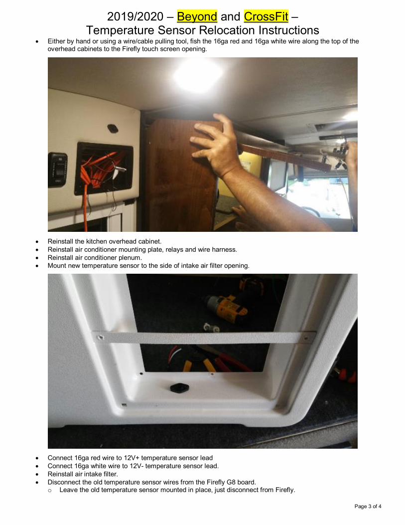
• Reinstall the kitchen overhead cabinet. • Reinstall air conditioner mounting plate, relays and wire harness. • Reinstall air conditioner plenum. • Mount new temperature sensor to the side of intake air filter opening.
• Connect 16ga red wire to 12V+ temperature sensor lead • Connect 16ga white wire to 12V- temperature sensor lead. • Reinstall air intake filter. • Disconnect the old temperature sensor wires from the Firefly G8 board.
o Leave the old temperature sensor mounted in place, just disconnect from Firefly.

2019/2020 – Beyond and CrossFit – Temperature Sensor Relocation Instructions
Page 4 of 4
• Connect the 16ga red wire to Pin 1 on J3 of Firefly G8 board. See “G8 Form” • Connect the 16ga white wire to Pin 7 on J3 of Firefly G8 board. See “G8 Form” • Power on Firefly system and verify temperature is reading properly. If it is not, reverse red and white wires. • Reinstall Firefly touch screen. • Verify A/C operation.

1
These instructions will describe the steps necessary to update your Firefly system to Version 4.20.
Follow the link to watch a short video of the process: https://youtu.be/q_pzQGCDOlE
Before beginning the update, please verify that you have received the following items:
• A USB flash drive labeled Version 4.20
• A programmer switch
• A G4 Terminator Tap
Please note that all lighting controlled by your Firefly system will turn off during the update. You may
find it necessary to use a flashlight for additional lighting.
Remove Your Touchscreen
To remove the touchscreen, simply place your
fingers along the top edge of the screen and apply
downward pressure while pulling out to “pop” the
screen out of the wall mount. Be careful not to
drop the screen once it breaks free.
Coachmen Galleria V4.20 Update
Programmer Switch
Flash Drive G4 Terminator Tap

2
Update the Touchscreen
Verify that your touchscreen is labeled Bootloader 2v0
then plug the USB flash drive into the back of the
screen. If your screen is not labeled Bootloader 2v0,
please contact Firefly Integrations.
Once the USB flash drive has been inserted into the
screen, power cycle your coach’s 12V house power.
The touchscreen will boot back up with the following
screen. Tap Auto Load.
Here you’ll see that 2 screen updates are required.
Tap Start Auto Load to install the required updates.
Once the screen has finished installing the required
updates, the status messages will read Update
Successful. Remove the flash drive and unplug the
network cable to disconnct the screen completely.
Flash Drive
4.20
4.20
4.20
4.20
V19
V19
V19
V19
3
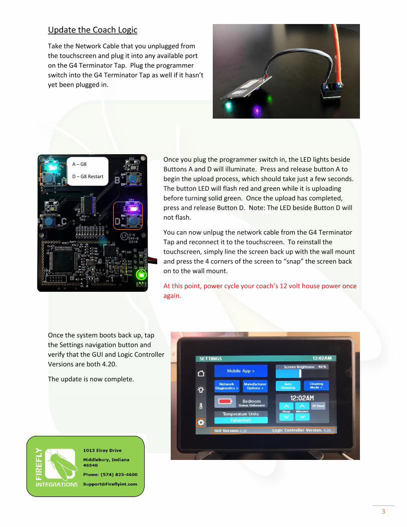
Update the Coach Logic
Take the Network Cable that you unplugged from
the touchscreen and plug it into any available port
on the G4 Terminator Tap. Plug the programmer
switch into the G4 Terminator Tap as well if it hasn’t
yet been plugged in.
Once you plug the programmer switch in, the LED lights beside
Buttons A and D will illuminate. Press and release button A to
begin the upload process, which should take just a few seconds.
The button LED will flash red and green while it is uploading
before turning solid green. Once the upload has completed,
press and release Button D. Note: The LED beside Button D will
not flash.
You can now unlpug the network cable from the G4 Terminator
Tap and reconnect it to the touchscreen. To reinstall the
touchscreen, simply line the screen back up with the wall mount
and press the 4 corners of the screen to “snap” the screen back
on to the wall mount.
At this point, power cycle your coach’s 12 volt house power once
again.
Once the system boots back up, tap
the Settings navigation button and
verify that the GUI and Logic Controller
Versions are both 4.20.
The update is now complete.
A – G8
D – G8 Restart
4.20 4.20