Technical Service Bulletin Audi - static.nhtsa.gov · 01 16 69 2033001 /8 July 27, 2016. Supersedes...
11
Technical Service Bulletin Audi 01 MIL on (P0491 and P0492 stored at same time 01 16 69 2033001 /8 July 27, 2016. Supersedes Technical Service Bulletin Group 01 number 14-97 dated October 2, 2014 for reasons listed below. Model(s) Year VIN Range Vehicle-Specific Equipment S4 2010 - 2012 All 3.2 FSI AVS and 3.0 TFSI A5 2010 All 3.2 FSI AVS and 3.0 TFSI S5 Cabriolet 2010 - 2013 All 3.2 FSI AVS and 3.0 TFSI A6 2009 - 2013 All 3.2 FSI AVS and 3.0 TFSI A7 2013 All 3.2 FSI AVS and 3.0 TFSI Q5 2010 - 2013 All 3.2 FSI AVS and 3.0 TFSI Q7 2011 -2012 All 3.2 FSI AVS and 3.0 TFSI Condition REVISION HISTORY Revision Date Purpose 8 - Revised header data (Added model year 2013) Revised Service (Updated air mass value readings based on software level) 7 10/2/2014 Revised Service (Added A6 (C6) 3.2FSI and Q7 3.0T instructions) Revised Required Parts and Tools (Updated coolant part number) 6 8/19/2014 Revised header data (Added model) Revised Warranty (Added labor operations) • MIL on. • Both of the following DTCs are stored in the engine control module, J623 (address word 01): • DTC P0491 (Secondary Air System Insufficient Flow, Bank 1) • DTC P0492 (Secondary Air System Insufficient Flow, Bank 2) • Mileage is greater than 15,000 miles. Technical Background Under certain driving conditions, the secondary air ports in the cylinder head can accumulate carbon over time, causing a restriction. Page 1 of 11 © 2016 Audi of America, Inc. All rights reserved. Information contained in this document is based on the latest information available at the time of printing and is subject to the copyright and other intellectual property rights of Audi of America, Inc., its affiliated companies and its licensors. All rights arc reserved to make changes at any time without notice. No part of this document may be reproduced, stored in a retrieval system, or transmitted in any form or by any means, electronic, mechanical, photocopying, recording, or otherwise, nor may these materials be modified or reposted to other sites, without the prior expressed written permission of the publisher.
Transcript of Technical Service Bulletin Audi - static.nhtsa.gov · 01 16 69 2033001 /8 July 27, 2016. Supersedes...
Technical Service Bulletin Audi
01 MIL on (P0491 and P0492 stored at same time
01 16 69 2033001 /8 July 27, 2016. Supersedes Technical Service Bulletin Group 01 number 14-97 dated October 2, 2014 for reasons listed below.
Model(s) Year VIN Range Vehicle-Specific Equipment
S4 2010 - 2012 All 3.2 FSI AVS and 3.0 TFSI
A5 2010 All 3.2 FSI AVS and 3.0 TFSI
S5 Cabriolet 2010 - 2013 All 3.2 FSI AVS and 3.0 TFSI
A6 2009 - 2013 All 3.2 FSI AVS and 3.0 TFSI
A7 2013 All 3.2 FSI AVS and 3.0 TFSI
Q5 2010 - 2013 All 3.2 FSI AVS and 3.0 TFSI
Q7 2011 -2012 All 3.2 FSI AVS and 3.0 TFSI
Condition
REVISION HISTORY
Revision Date Purpose
8 - Revised header data (Added model year 2013)
Revised Service (Updated air mass value readings based on software level)
7 10/2/2014 Revised Service (Added A6 (C6) 3.2FSI and Q7 3.0T instructions)
Revised Required Parts and Tools (Updated coolant part number)
6 8/19/2014 Revised header data (Added model)
Revised Warranty (Added labor operations)
• MIL on.
• Both of the following DTCs are stored in the engine control module, J623 (address word 01):
• DTC P0491 (Secondary Air System Insufficient Flow, Bank 1)
• DTC P0492 (Secondary Air System Insufficient Flow, Bank 2)
• Mileage is greater than 15,000 miles.
Technical Background
Under certain driving conditions, the secondary air ports in the cylinder head can accumulate carbon over time, causing a restriction.
Page 1 of 11 © 2016 Audi of America, Inc. All rights reserved. Information contained in this document is based on the latest information available at the time of printing and is subject to the copyright and other intellectual property rights of Audi of America, Inc., its affiliated companies and its licensors. All rights arc reserved to make changes at any time without notice. No part of this document may be reproduced, stored in a retrieval system, or transmitted in any form or by any means, electronic, mechanical, photocopying, recording, or otherwise, nor may these materials be modified or reposted to other sites, without the prior expressed written permission of the publisher.
Technical Service Bulletin Audi
Production Solution
Not applicable.
Service
Please note that before performing this repair for the first time, it is mandatory that the technician complete Audi Academy Course #940134 and assessment #940134B. Otherwise, the warranty claim will be denied. The course and assessment can be found on the Audi Academy CRC site. Specific video sections are reference in the instructions below.
Perform ODIS Testing - For all but AG (CG) 3.2FSI and Q7 3.0T:
1. Delete all DTCs. Bring the engine to operating temperature.
2. Go to Control Modules» 01 Engine Control Module» Control module 080» Basic Settings» Checking Secondary Air System.
3. Select MVB: MASS_SA_REL[0] and MASS_SA_REL[1].
4. Perform test (Press brake and gas pedal at the same time, start test on ODIS tester).
5. While Basic Setting test is running, check if the secondary air pump runs normally (no unusual noises). In addition, check for a leak in the secondary air hose routing between the pump and combi valves.
6. Immediately after the test is complete, read MASS_SA_REL[0] and MASS_SA_REL[1]. Depending on the software level and engine code, the air mass flow will be displayed in one of two ways:
• For old software version: If the value is between 0.1 and 0.7, and there were no issues with the pump and hoses, the system needs to be cleaned. Follow the instructions below.
• For new software version: If the value is between 13 and 16, and there were no issues with the pump and hoses, the system needs to be cleaned. Follow the instructions below.
Perform ODIS Testing - For AG (CG) 3.2FSI and Q7 3.0T only:
1 . Go to Control Modules » 01 Engine Control Module » Control module 080» Basic Settings » test 77.
2. While performing test 77, check if the secondary air pump is running and make sure it does not make any abnormal or unusual noise:
• If test 77 fails but the pump is running and does not make any abnormal/unusual noise, perform the cleaning process below.
• If the pump is not running or if it makes abnormal/unusual noise, replace the secondary air pump.
Page 2 of 11 © 2016 Audi of America, Inc. All rights reserved. Information contained in this document is based on the latest information available at the time of printing and is subject to the copyright and other intellectual property rights of Audi of America, Inc., its affiliated companies and its licensors. All rights arc reserved to make changes at any time without notice. No part of this document may be reproduced, stored in a retrieval system, or transmitted in any form or by any means, electronic, mechanical, photocopying, recording, or otherwise, nor may these materials be modified or reposted to other sites, without the prior expressed written permission of the publisher.
Technical Service Bulletin
[lJ Tip: Always use the latest version of this TSB.
Prepare for Power Washing
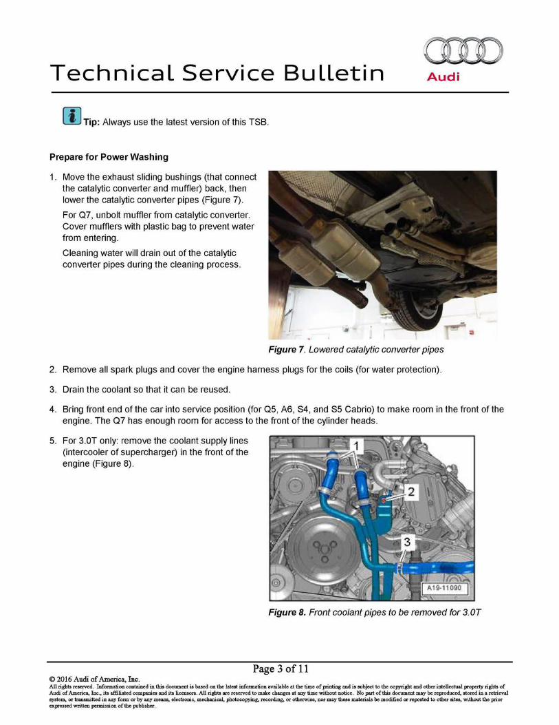
1. Move the exhaust sliding bushings (that connect the catalytic converter and muffler) back, then lower the catalytic converter pipes (Figure 7).
For Q7, unbolt muffler from catalytic converter. Cover mufflers with plastic bag to prevent water from entering.
Cleaning water will drain out of the catalytic converter pipes during the cleaning process.
Audi
Figure 7. Lowered catalytic converter pipes
2. Remove all spark plugs and cover the engine harness plugs for the coils (for water protection).
3. Drain the coolant so that it can be reused.
4. Bring front end of the car into service position (for QS, A6, S4, and S5 Cabrio) to make room in the front of the engine. The Q7 has enough room for access to the front of the cylinder heads.
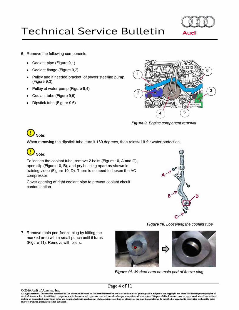
5. For 3.0T only: remove the coolant supply lines (intercooler of supercharger) in the front of the engine (Figure 8).
Figure 8. Front coolant pipes to be removed for 3.0T
Page 3 of 11 © 2016 Audi of America, Inc. All rights reserved. Information contained in this document is based on the latest information available at the time of printing and is subject to the copyright and other intellectual property rights of Audi of America, Inc., its affiliated companies and its licensors. All rights arc reserved to make changes at any time without notice. No part of this document may be reproduced, stored in a retrieval system, or transmitted in any form or by any means, electronic, mechanical, photocopying, recording, or otherwise, nor may these materials be modified or reposted to other sites, without the prior expressed written permission of the publisher.
Technical Service Bulletin Audi
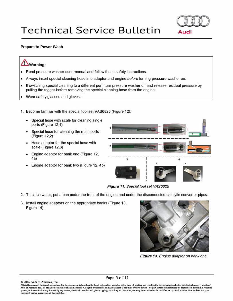
6. Remove the following components:
• Coolant pipe (Figure 9, 1)
• Coolant flange (Figure 9,2)
• Pulley and if needed bracket, of power steering pump (Figure 9,3)
• Pulley of water pump (Figure 9,4)
• Coolant tube (Figure 9,5)
• Dipstick tube (Figure 9,6)
Figure 9. Engine component removal
(I) Note:
When removing the dipstick tube, turn it 180 degrees, then reinstall it for water protection.
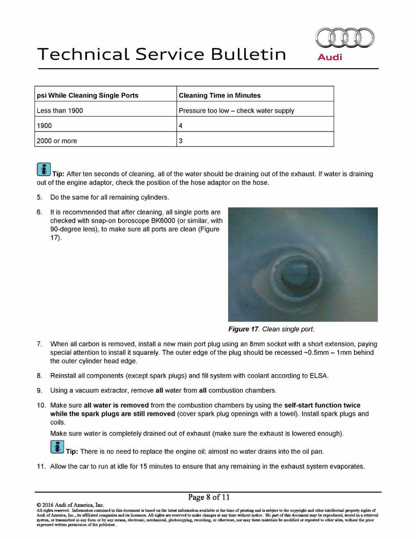
(I) Note:
To loosen the coolant tube, remove 2 bolts (Figure 10, A and C), open clip (Figure 10, B), and pry bushing apart as shown in training video (Figure 10, D). There is no need to loosen the AC compressor.
Cover opening of right coolant pipe to prevent coolant circuit contamination.
7. Remove main port freeze plug by hitting the marked area with a small punch until it turns (Figure 11). Remove with pliers.
D
Figure 10. Loosening the coolant tube
Figure 11. Marked area on main port of freeze plug.
Page 4 of 11 © 2016 Audi of America, Inc. All rights reserved. Information contained in this document is based on the latest information available at the time of printing and is subject to the copyright and other intellectual property rights of Audi of America, Inc., its affiliated companies and its licensors. All rights arc reserved to make changes at any time without notice. No part of this document may be reproduced, stored in a retrieval system, or transmitted in any form or by any means, electronic, mechanical, photocopying, recording, or otherwise, nor may these materials be modified or reposted to other sites, without the prior expressed written permission of the publisher.
Technical Service Bulletin Audi
Prepare to Power Wash
& warning:
• Read pressure washer user manual and follow these safety instructions.
• Always insert special cleaning hose into adaptor and engine before turning pressure washer on.
• If switching special cleaning to a different port, turn pressure washer off and release residual pressure by pulling the trigger before removing the special cleaning hose from the engine.
• Wear safety glasses and gloves.
1. Become familiar with the special tool set VAS6825 (Figure 12):
• Special hose with scale for cleaning single ports (Figure 12,1)
• Special hose for cleaning the main ports (Figure 12,2)
•
•
Hose adaptor for the special hose with scale (Figure 12,3) 2
Engine adaptor for bank one (Figure 12, 4a) 3 7 4
• Engine adaptor for bank two (Figure 12, 4b) I I I I I
Figure 11. Special tool set VAS6825
2. To catch water, put a pan under the front of the engine and under the disconnected catalytic converter pipes.
3. Install engine adaptors on the appropriate banks (Figure 13, Figure 14).
Page 5 of 11 © 2016 Audi of America, Inc.
Figure 13. Engine adaptor on bank one.
All rights reserved. Information contained in this document is based on the latest information available at the time of printing and is subject to the copyright and other intellectual property rights of Audi of America, Inc., its affiliated companies and its licensors. All rights arc reserved to make changes at any time without notice. No part of this document may be reproduced, stored in a retrieval system, or transmitted in any form or by any means, electronic, mechanical, photocopying, recording, or otherwise, nor may these materials be modified or reposted to other sites, without the prior expressed written permission of the publisher.

Technical Service Bulletin Audi
Figure 14. Engine adaptor on bank two.
4. To ensure proper pressure washer function, use a ¾-inch water supply hose (no longer than 60 feet) to supply pressure washer.
The Audi-supplied pressure washer comes with a 22mm male-to-male adapter (to connect special tool to trigger gun), a pressure gauge (to connect between pressure washer and high pressure hose), and a 220V power adapter.
Make sure that pressure is at least 1800 psi when using the special single port cleaning hose (the hose with the scale). Use the table below to compensate for low water pressure:
psi While Cleaning Single Ports
Less than 1900
1900
2000 or higher
Power Wash the Ports
Cleaning Main Secondary Port:
Cleaning Time in Minutes
Pressure too low - check water supply
4
3
1. Insert special main port cleaning hose (the hose without the scale) two inches into the engine adaptor.
2. Turn the pressure washer on.
3. Holding the cleaning hose tightly, pull the pressure washer trigger.
4. Gradually move the cleaning hose into the port, going back and forth until the combi valve is reached. All water comes out at the adaptor #4.
5. Continue going back and forth through the whole port until only clean water drains out of the cylinder head.
6. Do the same with the other cylinder head.
Page 6 of 11 © 2016 Audi of America, Inc. All rights reserved. Information contained in this document is based on the latest information available at the time of printing and is subject to the copyright and other intellectual property rights of Audi of America, Inc., its affiliated companies and its licensors. All rights arc reserved to make changes at any time without notice. No part of this document may be reproduced, stored in a retrieval system, or transmitted in any form or by any means, electronic, mechanical, photocopying, recording, or otherwise, nor may these materials be modified or reposted to other sites, without the prior expressed written permission of the publisher.

Technical Service Bulletin Audi
Cleaning Single Ports:
1. Because every port has a different distance to the cylinder head, use the table below to position the hose adaptor for the special single port cleaning hose (the hose with the scale) correctly into the hose. The back side of the hose adaptor must align with the number on the scale of the cylinder to be cleaned (Figure 14). The longitudinal slot on the hose adaptor must align with the black line on the scale for correct rotational positioning (Figure 15).
Dimensions Port 1 2 3
Bank One 10.5 19.5 28.5
Bank Two 13.7 22.7 31.8
Figure 15: Arrow indicating how the back side of the adaptor must align with the scale. Red dotted line indicating how the longitudinal slot must align with the black line on the scale.
2. After adjusting the position of the hose adaptor, insert the special single port cleaning hose into the hose adaptor, and bring it back into locking position (Figure 16).
Figure 16. Locking position ltransvers longitudinal movement and of the hose adaptor
3. While cleaning, make sure that the pressure washer is supplying pressure greater than 1800 psi.
4. Based on the washer's pressure, clean the port based on the table below. While cleaning, continuously move the hose adaptor within the longitudinal and transvers slots (Figure 16).
Page 7 of 11 © 2016 Audi of America, Inc. All rights reserved. Information contained in this document is based on the latest information available at the time of printing and is subject to the copyright and other intellectual property rights of Audi of America, Inc., its affiliated companies and its licensors. All rights arc reserved to make changes at any time without notice. No part of this document may be reproduced, stored in a retrieval system, or transmitted in any form or by any means, electronic, mechanical, photocopying, recording, or otherwise, nor may these materials be modified or reposted to other sites, without the prior expressed written permission of the publisher.
Technical Service Bulletin Audi
psi While Cleaning Single Ports Cleaning Time in Minutes
Less than 1900 Pressure too low - check water supply
1900 4
2000 or more 3
[I) Tip: After ten seconds of cleaning, all of the water should be draining out of the exhaust. If water is draining out of the engine adaptor, check the position of the hose adaptor on the hose.
5. Do the same for all remaining cylinders.
6. It is recommended that after cleaning, all single ports are checked with snap-on boroscope BK6000 (or similar, with 90-degree lens), to make sure all ports are clean (Figure 17).
Figure 17. Clean single port.
7. When all carbon is removed, install a new main port plug using an 8mm socket with a short extension, paying special attention to install it squarely. The outer edge of the plug should be recessed -0.5mm - 1 mm behind the outer cylinder head edge.
8. Reinstall all components (except spark plugs) and fill system with coolant according to ELSA.
9. Using a vacuum extractor, remove all water from all combustion chambers.
10. Make sure all water is removed from the combustion chambers by using the self-start function twice while the spark plugs are still removed (cover spark plug openings with a towel). Install spark plugs and coils.
Make sure water is completely drained out of exhaust (make sure the exhaust is lowered enough).
[I) Tip: There is no need to replace the engine oil; almost no water drains into the oil pan.
11. Allow the car to run at idle for 15 minutes to ensure that any remaining in the exhaust system evaporates.
Page 8 of 11 © 2016 Audi of America, Inc. All rights reserved. Information contained in this document is based on the latest information available at the time of printing and is subject to the copyright and other intellectual property rights of Audi of America, Inc., its affiliated companies and its licensors. All rights arc reserved to make changes at any time without notice. No part of this document may be reproduced, stored in a retrieval system, or transmitted in any form or by any means, electronic, mechanical, photocopying, recording, or otherwise, nor may these materials be modified or reposted to other sites, without the prior expressed written permission of the publisher.

Technical Service Bulletin Audi
After Power Washing
1. Delete all DTCs. Bring engine to operating temperature.
2. Go to Control Modules» 01 Engine Control Module» Control module 080 » Basic Settings» Checking Secondary Air System.
3. Select MVB: MASS_SA_REL[0] and MASS_SA_REL[1].
4. Perform test (Press brake and gas pedal at the same time, start test on ODIS tester).
5. Immediately after the test is complete, read MASS_SA_REL[0] and MASS_SA_REL[1].
• For old software version: If the value is between 0.9 and 1.0, the cleaning was successful.
• For new software version: If the value is between O and 5, the cleaning was successful.
Warranty
Claim Type: 1EB
Service Number: 2644
Damage Code: 0010
Labor Operations: Q5 CALB engine (525)
Coolant pipe remove + reinstall
Power steering pump remove+ reinstall (overlap reduced includes time for exhaust and spark plugs)
Loosen/fasten lock carrier
Pressure wash
AG CALA engine (555)
Coolant pipe remove + reinstall
Power steering pump remove+ reinstall (overlap reduced includes time for exhaust and spark plugs)
Loosen/fasten lock carrier
Pressure wash
Page 9 of 11 © 2016 Audi of America, Inc.
1961 1906
4898 1999
5038 0900
2644 1999
1961 1906
4898 1999
5038 0900
2644 1999
250 TU
60 TU
160 TU
75 TU
220 TU
60 TU
220 TU
75 TU
All rights reserved. Information contained in this document is based on the latest information available at the time of printing and is subject to the copyright and other intellectual property rights of Audi of America, Inc., its affiliated companies and its licensors. All rights arc reserved to make changes at any time without notice. No part of this document may be reproduced, stored in a retrieval system, or transmitted in any form or by any means, electronic, mechanical, photocopying, recording, or otherwise, nor may these materials be modified or reposted to other sites, without the prior expressed written permission of the publisher.

Technical Service Bulletin
AS CALA engine (525)
Coolant pipe remove + reinstall
Power steering pump remove+ reinstall (overlap reduced includes time for exhaust and spark plugs)
Loosen/fasten lock carrier
Pressure wash
AG CCAA engine (625)
Coolant pipe remove + reinstall
Power steering pump remove+ reinstall (overlap reduced includes time for exhaust and spark plugs)
Loosen/fasten lock carrier
Pressure wash
A6/A7 CGXB engine (575)
Coolant pipe remove + reinstall
Power steering pump remove+ reinstall (overlap reduced includes time for exhaust and spark plugs)
Loosen/fasten lock carrier
Pressure wash
54, 55, 55 cab CCBA engine (565)
Coolant pipe remove + reinstall
Power steering pump remove+ reinstall (overlap reduced includes time for exhaust and spark plugs)
Loosen/fasten lock carrier
Pressure wash
Q7 CJWE, CJWC, CJWB engines (335)
Coolant pipe remove + reinstall
Power steering pump remove+ reinstall (overlap reduced includes time for exhaust and spark plugs)
Pressure wash
Page 10 of 11 © 2016 Audi of America, Inc.
1961 1906
4898 1999
5038 0900
2644 1999
1961 1941
4898 1999
5038 0900
2644 1999
1961 1999
4898 1999
5038 0999
2644 1999
1961 1941
4898 1999
5038 0900
2644 1999
1961 2039
4898 1999
2644 1999
Audi
250 TU
60 TU
160 TU
75 TU
290 TU
60 TU
220 TU
75 TU
220 TU
60 TU
220 TU
75 TU
290 TU
60 TU
160 TU
75 TU
220 TU
60 TU
75 TU
All rights reserved. Information contained in this document is based on the latest information available at the time of printing and is subject to the copyright and other intellectual property rights of Audi of America, Inc., its affiliated companies and its licensors. All rights arc reserved to make changes at any time without notice. No part of this document may be reproduced, stored in a retrieval system, or transmitted in any form or by any means, electronic, mechanical, photocopying, recording, or otherwise, nor may these materials be modified or reposted to other sites, without the prior expressed written permission of the publisher.
Technical Service Bulletin Audi
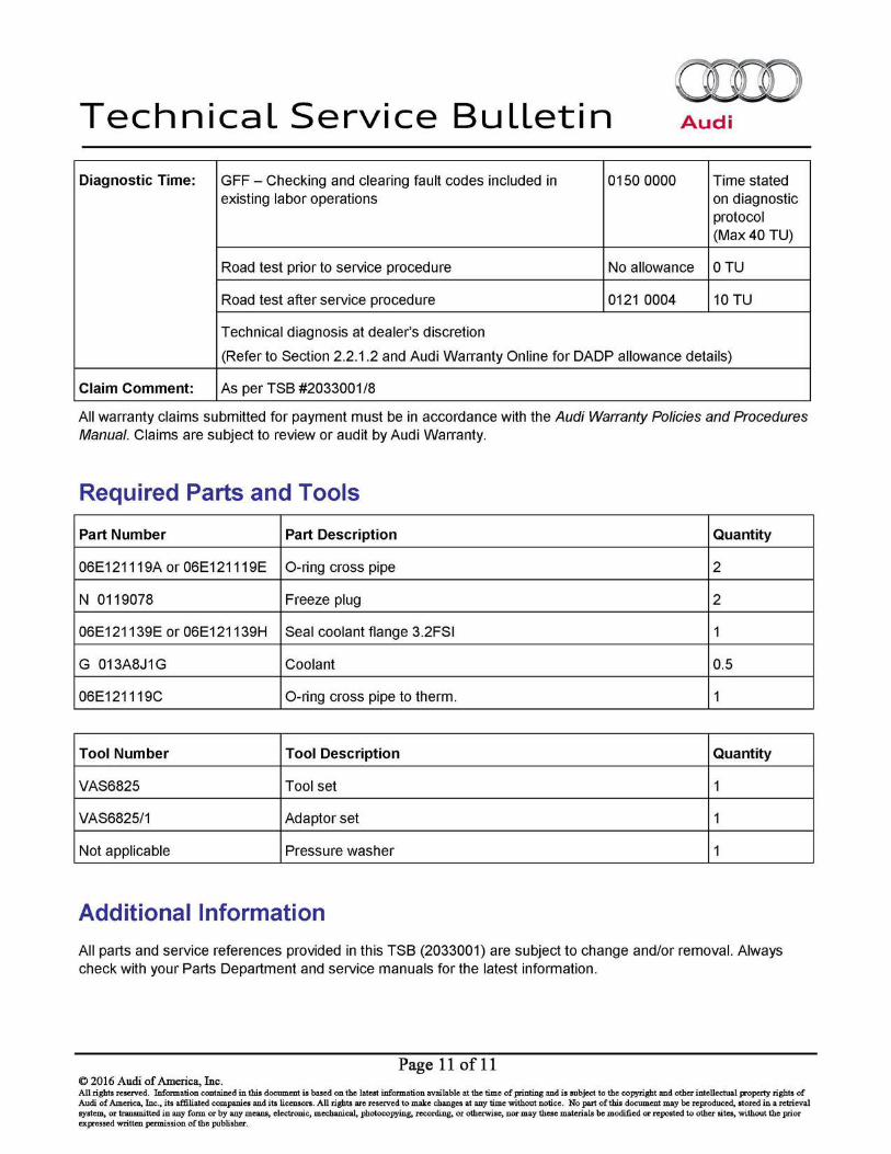
Diagnostic Time: GFF - Checking and clearing fault codes included in 0150 0000 Time stated existing labor operations on diagnostic
protocol (Max40 TU)
Road test prior to service procedure No allowance 0TU
Road test after service procedure 0121 0004 10 TU
Technical diagnosis at dealer's discretion
(Refer to Section 2.2.1.2 and Audi Warranty Online for DADP allowance details)
Claim Comment: As per TSB #2033001/8
All warranty claims submitted for payment must be in accordance with the Audi Warranty Policies and Procedures Manual. Claims are subject to review or audit by Audi Warranty.
Required Parts and Tools
Part Number Part Description Quantity
06E121119A or 06E121119E O-ring cross pipe 2
N 0119078 Freeze plug 2
06E121139E or 06E121139H Seal coolant flange 3.2FSI 1
G 013A8J1G Coolant 0.5
06E121119C O-ring cross pipe to therm. 1
Tool Number Tool Description Quantity
VAS6825 Tool set 1
VAS6825/1 Adaptor set 1
Not applicable Pressure washer 1
Additional Information
All parts and service references provided in this TSB (2033001) are subject to change and/or removal. Always check with your Parts Department and service manuals for the latest information.
Page 11 of 11 © 2016 Audi of America, Inc. All rights reserved. Information contained in this document is based on the latest information available at the time of printing and is subject to the copyright and other intellectual property rights of Audi of America, Inc., its affiliated companies and its licensors. All rights arc reserved to make changes at any time without notice. No part of this document may be reproduced, stored in a retrieval system, or transmitted in any form or by any means, electronic, mechanical, photocopying, recording, or otherwise, nor may these materials be modified or reposted to other sites, without the prior expressed written permission of the publisher.