Technical Review NO.04(E)
11
051 JR EAST Technical Review-No.4 The company is undertaking research and development into themes that have to do with the environment with the following three objectives: reduction of CO2 gas emissions, achievement of zero emission, and harmony with the environment along railway routes. Advances in technology are rapid and this age is one of fierce technical innovation that makes it possible within the next five to ten years to accomplish things used to be thought beyond our capability. We conduct our development efforts firmly believing that things that may seem to be but a dream will become reality in the future. Interpretive Article "Towards the Future Materialization of an Environment Friendly Railway" Yukio Arimori Managing Director, Manager of Technical Planning and Director of the Research and Development Center, JR East Group JR East Railway Company this reason, the train may be operated commercially as soon as the performance of the engine generator or storage batteries have been confirmed. Upon startup of operation, electric power is supplied from the storage battery. When the speed of the vehicle reaches 25 km/h or more, the engine begins to operate and to generate electricity that is then used to provide motive power to the vehicle. The engine generates electricity at a fixed rotation speed which provides optimum performance and the energy generated is stored in the storage battery. I will first speak about how JR East Railway Company is contributing to the environment from the technical perspective. The company is undertaking research and development into themes that have to do with the environment with the following three objectives: reduction of CO2 gas emissions, achievement of zero emission, and harmony with the environment along railway routes. 2.1 Hybrid Vehicle NE Train (New Energy Train) This is a vehicle (Fig.1) that employs a hybrid system under the concept of reducing the burden on the environment exerted by vehicles through innovation in the propulsion system. The vehicle was completed in the spring of 2003 and is currently undergoing operation testing. The use of fuel cells in the future is kept in perspective and the objective of the development effort is energy saving, reduction of exhaust gas and noise, reduction of maintenance needs, and improvement of operational performance. The biggest issues that must be addressed when developing a new vehicle are safety and stability and in the case of this new train, the main truck and transmission system utilizes the mass-produced E231 Series. For Fig.1: Development Concept of the NE Train 1 Introduction 2 Environment Friendly Trains Fig.2: Hybrid System Control Mode
Transcript of Technical Review NO.04(E)

051JR EAST Technical Review-No.4
The company is undertaking research and development into themes that have to do with the environment with the following three objectives:
reduction of CO2 gas emissions, achievement of zero emission, and harmony with the environment along railway routes. Advances in
technology are rapid and this age is one of fierce technical innovation that makes it possible within the next five to ten years to accomplish
things used to be thought beyond our capability. We conduct our development efforts firmly believing that things that may seem to be but a
dream will become reality in the future.
Interpretive Article"Towards the Future Materialization ofan Environment Friendly Railway"
Yukio ArimoriManaging Director, Manager of Technical Planning and Director of the Research and Development Center, JR East Group
JR East Railway Company
this reason, the train may be operated commercially as soon as the
performance of the engine generator or storage batteries have been
confirmed.
Upon startup of operation, electric power is supplied from the storage
battery. When the speed of the vehicle reaches 25 km/h or more, the
engine begins to operate and to generate electricity that is then used
to provide motive power to the vehicle. The engine generates
electricity at a fixed rotation speed which provides optimum
performance and the energy generated is stored in the storage battery.
I will first speak about how JR East Railway Company is contributing
to the environment from the technical perspective. The company is
undertaking research and development into themes that have to do
with the environment with the following three objectives: reduction of
CO2 gas emissions, achievement of zero emission, and harmony with
the environment along railway routes.
2.1 Hybrid Vehicle NE Train (New Energy Train)
This is a vehicle (Fig.1) that employs a hybrid system under the
concept of reducing the burden on the environment exerted by
vehicles through innovation in the propulsion system. The vehicle
was completed in the spring of 2003 and is currently undergoing
operation testing. The use of fuel cells in the future is kept in
perspective and the objective of the development effort is energy
saving, reduction of exhaust gas and noise, reduction of maintenance
needs, and improvement of operational performance. The biggest
issues that must be addressed when developing a new vehicle are
safety and stability and in the case of this new train, the main truck
and transmission system utilizes the mass-produced E231 Series. For
Fig.1: Development Concept of the NE Train
1 Introduction
2 Environment Friendly Trains
Fig.2: Hybrid System Control Mode

052 JR EAST Technical Review-No.4
Interpretive Article
been reduced, the car structure allows larger car space. Moreover,
the AC train uses a conveyance system called LON that reduces wiring
by about 60%. This allows for greater safety in that, for example, if
one device for closing the doors should break down, the doors can
still be operated normally using a different device. ATS-P safety
devices are installed in both driver cabs on each end of the train, so
that control is possible even in the case of a breakdown. Each system
is independent, decentralized, and capable of self-diagnosis.
The AC train employs the articulated structure in order to achieve
lighter vehicle weight (Figure 4). In the case of the normal bogie
structure of a 10 car configuration, four of the cars provide the driving
power. Or in terms of axles, there are 16 drive-axles. There was a
problem in that if this car, which is driven by the so-called 4M6T style
drive-power, were to be made any lighter, the axle weight of the
bogie structure would become too light, and not be able to provide
the required degree of traction. For this reason, the articulated
structure was employed targeting a lighter weight than the E231 Series
Upon braking, electricity that is produced by the regenerative motor
charges the storage battery. Energy that could not be regenerated in
legacy rail cars may be stored in the battery as energy and this targets
a significant reduction of energy use (Figure 2).
The results of the tests thus far show that the target value of reduction
of energy consumption by 20% is close to being met. With respect to
operational performance, the train is able to provide acceleration of
2.3 km/h/s at a speed of 35 km/h and this is about on par with
normal trains. Since the engine stops when the train stops at stations
or is being operated at a low speed, noise at the station platform may
also be reduced.
2.2 AC Train: the Next Generation Commuter Train
The development of the AC train has targeted cost reduction,
improved stability of transportation, improved services to passengers,
barrier free construction, and ecology (Figure 3). Operation testing in
excess of 100,000 kilometers has been conducted since last year. The
train has a new type of motor called DDM (Direct Drive Motor) and
with respect to this, in addition to tests conducted on the prototype
train, accelerated tests are being conducted at the Omiya research and
development center using a truck testing device repeating run and
stop in cycles of 70 seconds. This represents durability test equivalent
to 250,000 kilometers of actual operation.
Targeting system change and cost reduction, the structure of the car
that has been employed is the articulated structure rather than the
bogie structure that is mainly employed in railway vehicles at the
present. The motor is DDM and employs a structure whereby the
energy from the rotating shaft is conveyed directly to the wheels, thus
improving energy efficiency. As there is no gear box, noise is also
reduced. With respect to barrier free construction, both the
wheelchair slope and wheelchair step are operating in a satisfactory
manner. From the perspective of ecology, zero emission has been
achieved by using materials that are all recyclable and reusable.
Improved services involve the positioning of information service
displays in the door pockets to convey various information and
advertising to the passengers. With the articulated structure, there is
no partitioning between cars and since the length of each car has
Fig.3: AC Train: the Next Generation Commuter Train
Fig.4: Articulated structure

053JR EAST Technical Review-No.4
Interpretive Article-1
and reducing the number of drive axles. Since the length of each car
is shorter, the number of cars in a train configuration will increase,
but with the same total length of 200 meters, there is the merit of a
train configuration that is currently being driven by 16 axles being
driven instead by 12 axles. The weight of a car as a whole has been
reduced by 8%.
The DDM system connects the motor directly to the drive axles
(Figure 5). Since the wheels are driven directly, there is no need for a
gear box. In other words, the train is operated at the rotation speed
of the motor without implementing any step down in the rotating
speed. Since the motor rotates at a low speed, the noise from the
motor itself is reduced and since there is no gear box, there is no gear
box noise. Moreover, a system that does away with the need to
intake external cooling air has been devised. As a result, the train is
capable in principle of being operated for 13 years without
maintenance and the use of DDM has resulted in energy saving of
about 10% and reduction of noise of 5 dB compared to the E231
Series.
2.3 Future Image of Environment Friendly Trains
The final target for the NE train is to mount fuel cells in the place of
the engine. It is thought that this will be possible in 10 to 15 years
and one of the dreams we envision is to introduce fuel cell trains on
the Yamanote line. Here I will explain the feasibility of this in terms
of improvement in the fuel cell and the supply of hydrogen as well as
the reduction of cost.
The image of a railway route plied by fuel cell trains is a simple one
that requires no overhead line equipment (Figure 7). The hydrogen
storage tank will, in principle, be mounted on the roof. A direct drive
motor will be used and the fuel cell will be mounted below the floor.
In the case of the Yamanote line, one complete loop is comprised of
29 stations, and acceleration and deceleration are constantly repeated
between these stations so that the energy from deceleration may be
stored in a secondary battery to raise energy efficiency. In a review
undertaken several years ago, the conclusion was that the fuel cell
would need to have considerably large capacity, but by combining it
with the secondary battery, it has now become clear that a small
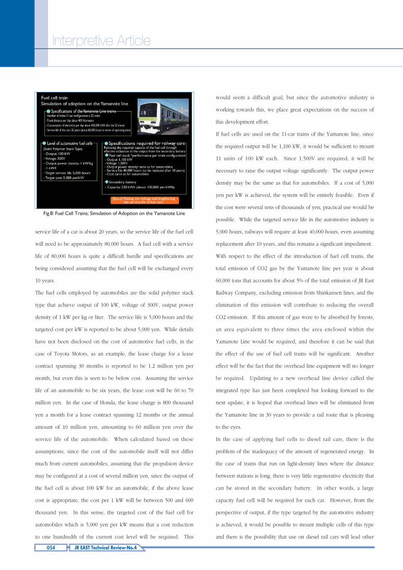
capacity fuel cell will be sufficient. Here I will explain the
specifications of the fuel cell required for adopting this to the 52
trains of the Yamanote line (Figure 8). Trains on the Yamanote line
travel about 400 kilometers per day and the 52 trains as a whole
consume approximately 450,000 kWh of electricity per day. The
Fig.6: Transition in the Volume of Electricity Required by Trains Fig.7: Image of a Fuel Cell Train
Fig.5: DDM (Direct Drive Motor)
054 JR EAST Technical Review-No.4
Interpretive Article
service life of a car is about 20 years, so the service life of the fuel cell
will need to be approximately 80,000 hours. A fuel cell with a service
life of 80,000 hours is quite a difficult hurdle and specifications are
being considered assuming that the fuel cell will be exchanged every
10 years.
The fuel cells employed by automobiles are the solid polymer stack
type that achieve output of 100 kW, voltage of 300V, output power
density of 1 kW per kg or liter. The service life is 5,000 hours and the
targeted cost per kW is reported to be about 5,000 yen. While details
have not been disclosed on the cost of automotive fuel cells, in the
case of Toyota Motors, as an example, the lease charge for a lease
contract spanning 30 months is reported to be 1.2 million yen per
month, but even this is seen to be below cost. Assuming the service
life of an automobile to be six years, the lease cost will be 60 to 70
million yen. In the case of Honda, the lease charge is 800 thousand
yen a month for a lease contract spanning 12 months or the annual
amount of 10 million yen, amounting to 60 million yen over the
service life of the automobile. When calculated based on these
assumptions, since the cost of the automobile itself will not differ
much from current automobiles, assuming that the propulsion device
may be configured at a cost of several million yen, since the output of
the fuel cell is about 100 kW for an automobile, if the above lease
cost is appropriate, the cost per 1 kW will be between 500 and 600
thousand yen. In this sense, the targeted cost of the fuel cell for
automobiles which is 5,000 yen per kW means that a cost reduction
to one hundredth of the current cost level will be required. This
Fig.8: Fuel Cell Trains; Simulation of Adoption on the Yamanote Line
would seem a difficult goal, but since the automotive industry is
working towards this, we place great expectations on the success of
this development effort.
If fuel cells are used on the 11-car trains of the Yamanote line, since
the required output will be 1,100 kW, it would be sufficient to mount
11 units of 100 kW each. Since 1,500V are required, it will be
necessary to raise the output voltage significantly. The output power
density may be the same as that for automobiles. If a cost of 5,000
yen per kW is achieved, the system will be entirely feasible. Even if
the cost were several tens of thousands of yen, practical use would be
possible. While the targeted service life in the automotive industry is
5,000 hours, railways will require at least 40,000 hours, even assuming
replacement after 10 years, and this remains a significant impediment.
With respect to the effect of the introduction of fuel cell trains, the
total emission of CO2 gas by the Yamanote line per year is about
60,000 tons that accounts for about 5% of the total emission of JR East
Railway Company, excluding emission from Shinkansen lines, and the
elimination of this emission will contribute to reducing the overall
CO2 emission. If this amount of gas were to be absorbed by forests,
an area equivalent to three times the area enclosed within the
Yamanote Line would be required, and therefore it can be said that
the effect of the use of fuel cell trains will be significant. Another
effect will be the fact that the overhead line equipment will no longer
be required. Updating to a new overhead line device called the
integrated type has just been completed but looking forward to the
next update, it is hoped that overhead lines will be eliminated from
the Yamanote line in 30 years to provide a rail route that is pleasing
to the eyes.
In the case of applying fuel cells to diesel rail cars, there is the
problem of the inadequacy of the amount of regenerated energy. In
the case of trains that run on light-density lines where the distance
between stations is long, there is very little regenerative electricity that
can be stored in the secondary battery. In other words, a large
capacity fuel cell will be required for each car. However, from the
perspective of output, if the type targeted by the automotive industry
is achieved, it would be possible to mount multiple cells of this type
and there is the possibility that use on diesel rail cars will lead other

055JR EAST Technical Review-No.4
Interpretive Article-1
applications.
The supply of hydrogen is another significant issue (Figure 9).
Practical use of up to 350 atmospheres of high pressure hydrogen has
become possible. With respect to liquid hydrogen, low temperature
management is a problem, as is the fact that hydrogen absorbing alloy
is extremely heavy. Pilot hydrogen stations for automobiles have
been installed in 10 locations. For on-site types (a type of station
whereby the hydrogen is produced at the station itself), the capacity
for producing hydrogen is 700 Nm3 per day while for the off-site type
whereby the hydrogen is transported using trailer cars, the volume
per trailer is 1,000 Nm3. When this is considered from the
perspective of providing hydrogen to trains, in the case of the
Yamanote line, the requirements are 5,200 Nm3 or 450 kg per train
(Figure 10). If high pressure hydrogen or liquid hydrogen were to be
used, the volume that can be loaded is 11,000 liters or less per train
when the configuration of the train is taken into consideration. For
this reason, the volume density of the high pressure hydrogen and
liquid hydrogen will need to be 0.5 Nm3 per liter. If hydrogen is to
be supplied through a hydrogen absorbing substance, the weight that
may be loaded will be 11 tons per 11-car train or 1 ton per car so that
4 wt% will be required as weight density of the hydrogen. Looking at
the current technical level of suppliers, the 350 atmosphere level has
already been achieved as mentioned earlier. The 700 atmosphere
level is currently under development, but since the volume density at
this level will still be 0.3 Nm3 per liter, even at this level, 0.5 Nm3 per
liter will not be achieved. While the volume density is 0.4 Nm3 per
liter in the case of liquid hydrogen, even this will not reach the 0.5
Nm3 per liter level. The system that offers the best hope is hydrogen
absorbing substance into which the hydrogen will be absorbed. Since
the weight density is 3 wt%, raising this by 1% will enable practical
use. Daily transportation of 5,200 Nm^3 or 450 kg of hydrogen is an
enormous task and since as a whole, the daily supply in volume
terms must be 270 thousand Nm3 or more, a replaceable cassette type
of a hydrogen absorbing substance would seem the most practicable
method available. If the cost of the fuel falls to 17 yen or less per 1
Nm3, this would allow changing from the current overhead line
device system (Figure 11).
Fig.11: Hydrogen Supply Facility
There are representatives from manufacturers participating in this
symposium today, and I would request that they provide information
on this, if available, later on during this symposium.
Fig.9: Hydrogen Station
Fig.10: Hydrogen Storing Technology

056 JR EAST Technical Review-No.4
Interpretive Article
3.1 Zero Emission by Railway Trains
The rate of recycling of railway trains of the past was 94% but the AC
Train is being developed with "zero emission" as a target and, for
example materials that may be reused or recycled are used in FRP
parts, floor framing, glass wool, and polyvinyl chloride. No
consideration is given to thermal recycling (Figure 12).
With respect to FRP, after removing the FRP from a discarded vehicle,
the material is separated into fiber, resin, and filler and the retrieved
material is formed and recycled into vehicle material. In the case of
recycling factory waste into resources, for example, brake lining is
recycled as pad material and base material and the base material is
recycled as iron. In the case of the carbon brush for the main motor,
since the alternating current motor is primarily being used in recent
years, the carbon brush itself will eventually go into disuse, but even
so, there are old types of trains and technology for separation of this
material is being developed.
3.2 Lengthening the Service Life of Railway Facilities
Maintenance free TC type energy saving tracks have been in use on
the Yamanote line (Figure 13) since 1998. In the future, the intention
is to introduce this system on tracks used by freight trains and in
places where the tracks are relatively weak as reinforcing structure.
The testing equipment at the research and development center is
currently being used to develop this type of energy saving track.
Railroad ties and ballast generated as byproducts during the
construction are reused as material for road-bed foundation.
With respect to the lengthening of the service life of the rails, the
standard for replacement is 600 million tons or 800 million tons for
normal gauge lines and 600 million tons for Shinkansen in terms of
accumulated service tonnage of the rails and the intention is to
lengthen this by about 200 million tons. Experiments are currently
being conducted at the research and development center with respect
to the fatigue durability of the rail joints through load and stress
measurements (Figure 14). Moreover, research is being conducted on
a method of lightly grinding the surface of a rail prior to the
occurrence of shelling to prevent damage to the rail in order to
ensure that rails may be used until the standard replacement time
based on accumulated service tonnage without the need for earlier
replacement.
Fig.13: TC Type Energy Saving Tracks
Fig.14: Lengthening the Service Life of Rails
Fig.12: Zero Emission from AC Trains
3 Zero Emission

057JR EAST Technical Review-No.4
Interpretive Article-1
With respect to contact lines, carbon contact slips have been
introduced in a significant proportion of the routes and abrasion has
been reduced to about 1/3 the level of the previous system.
However, research is currently being conducted in order to increase
the service life of the contact lines by another 30% through changing
the material of the contact lines themselves (Figure 15). The intention
is to use material that is stronger and with higher electric conductivity
than the current material and fatigue durability experiments are being
conducted at the research and development center on materials to
which tin, chrome, zirconium, aluminum or indium has been added.
4.1 Self Generation of Electricity
JR East Railway supplies about 56% of its electricity needs through
Fig.16: Self Generation of Electricity
Fig.17: Solar Electricity Generating System
self-operated hydro and thermal power generation facilities (Figure
16). There is a target to reduce the emission of CO2 gas per unit of
power generation by 30% from the level in fiscal 1990, and the
amount of 726 grams in fiscal 1990 has been reduced to 519 grams.
With respect to a goal of achieving 508 grams by fiscal 2005,
achievement is now close at hand.
4.2 Generation of Natural Energy
Solar cells constitute a method of natural generation of energy and
experiments are being confirmed in a variety of locations (Figure 17).
A 100 kW class solar generation system that is integrated into
construction material has been installed on the roof of the Takasaki
Station platform since 2001. Moreover, a pyramid shaped solar panel
and a plate shaped panel are installed in the hall of the research and
development center in order to confirm the electricity generating
performance. For those with the panel installed on one side, the
electricity generating capacity is about 130 W per square meter.
There are also four solar panels units that are capable of receiving
light from both directions that have been installed and are being
tested in the research and development center and in this case, the
average amount of electricity generated is 160 W per square meter,
indicating that panels capable of receiving light from both directions
provide just under 40% greater generating capacity. Research on the
optimum installation of such panels will continue in the future.4 Supply of Energy
Fig.15: Lengthening the Service Life of Contact Points
058 JR EAST Technical Review-No.4
Interpretive Article
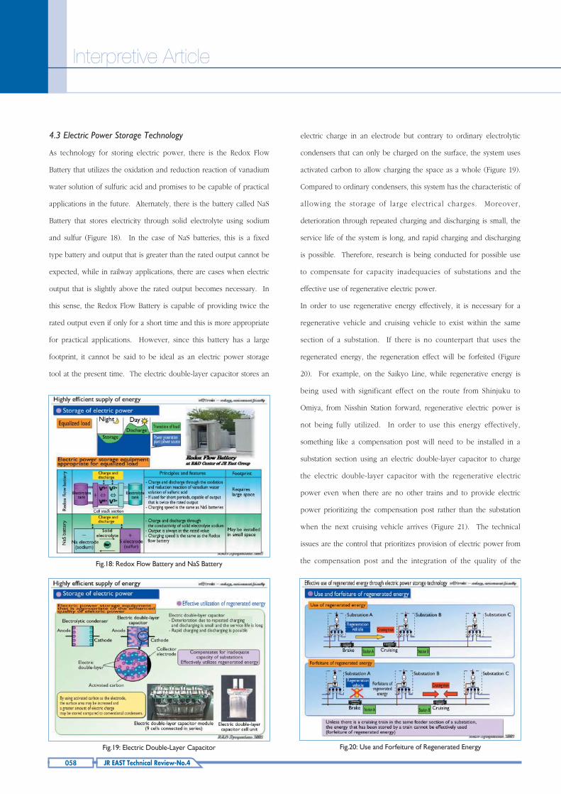
4.3 Electric Power Storage Technology
As technology for storing electric power, there is the Redox Flow
Battery that utilizes the oxidation and reduction reaction of vanadium
water solution of sulfuric acid and promises to be capable of practical
applications in the future. Alternately, there is the battery called NaS
Battery that stores electricity through solid electrolyte using sodium
and sulfur (Figure 18). In the case of NaS batteries, this is a fixed
type battery and output that is greater than the rated output cannot be
expected, while in railway applications, there are cases when electric
output that is slightly above the rated output becomes necessary. In
this sense, the Redox Flow Battery is capable of providing twice the
rated output even if only for a short time and this is more appropriate
for practical applications. However, since this battery has a large
footprint, it cannot be said to be ideal as an electric power storage
tool at the present time. The electric double-layer capacitor stores an
electric charge in an electrode but contrary to ordinary electrolytic
condensers that can only be charged on the surface, the system uses
activated carbon to allow charging the space as a whole (Figure 19).
Compared to ordinary condensers, this system has the characteristic of
allowing the storage of large electrical charges. Moreover,
deterioration through repeated charging and discharging is small, the
service life of the system is long, and rapid charging and discharging
is possible. Therefore, research is being conducted for possible use
to compensate for capacity inadequacies of substations and the
effective use of regenerative electric power.
In order to use regenerative energy effectively, it is necessary for a
regenerative vehicle and cruising vehicle to exist within the same
section of a substation. If there is no counterpart that uses the
regenerated energy, the regeneration effect will be forfeited (Figure
20). For example, on the Saikyo Line, while regenerative energy is
being used with significant effect on the route from Shinjuku to
Omiya, from Nisshin Station forward, regenerative electric power is
not being fully utilized. In order to use this energy effectively,
something like a compensation post will need to be installed in a
substation section using an electric double-layer capacitor to charge
the electric double-layer capacitor with the regenerative electric
power even when there are no other trains and to provide electric
power prioritizing the compensation post rather than the substation
when the next cruising vehicle arrives (Figure 21). The technical
issues are the control that prioritizes provision of electric power from
the compensation post and the integration of the quality of theFig.18: Redox Flow Battery and NaS Battery
Fig.19: Electric Double-Layer Capacitor Fig.20: Use and Forfeiture of Regenerated Energy

059JR EAST Technical Review-No.4
electric double-layer capacitor itself. Today, as demand is small,
production is on a small scale and status of manufacturing is not as an
industrial product but rather as a hand-made product so that the price
is extremely high. However, the cost has come down from the 1.2
million yen per kW in 1998 to 600 thousand yen per kW at the
present time. As a result of trial calculation of the price at which this
system can actually be adopted, the price per kW would need to be
30 thousand yen or 1/20 the current level. If demand increases and
line manufacturing becomes possible, there is the possibility of
significant cost reduction and we believe that the concept is not
entirely without promise.
4.4 New Heat Exchangers
There is a device called a heat exchange element of a semiconductor
(Figure 22). The heat exchange efficiency of this device is extremely
high at 93%. Moreover, electric power consumption may be reduced
by 30% or more and since the material is not self-igniting, the system
ensures safety.
In the winter of 2003, this heater was affixed under the floor of the
Shinkansen vehicle Komachi to test prevention of snow accumulation.
When a voltage is applied to this semiconductor heat exchange
element after snow has adhered, heat is generated. While a high
temperature is reached almost instantaneously, since the calorific
capacity is small, the applications are limited, but with certain types,
the temperature may be raised to 1,000 degrees in several seconds.
The effect of this heater melting the surface with which it is in contact
and causing the lumps of snow to slip away has been confirmed and
this effect has been named "skate effect."
Since this is a significantly effective method for freely dropping off the
accumulated snow, the intention is to conduct a test by attaching this
heat exchanger to a complete Komachi train in the winter of 2004. In
addition, it also has possibilities for application to melting
accumulated snow from switch points, depending on the properties
of the snow, and tests are planned in this regard as well.
The stations of the future will need to take into consideration such
aspects as solar energy, collection of heat, passive control, generation
of natural energy, and use of greenery from the perspective of energy
savings (Figure 23). In terms of material, natural materials, materials
Interpretive Article-1
Fig.22: New Heating element (Semiconductor Heat Exchange Element)
Fig.21: Effective Use of Regenerated Energy
5 Eco-Station
Fig.23: Eco-Station

060 JR EAST Technical Review-No.4
that may be recycled, and materials that are healthy for humans will
need to be used and the design will need to adopt eco-design and
universal design. Stations that are people friendly and environment
friendly have not been achieved as of yet but when building stations
in the future, the intention is to adopt this concept.
6.1 Overview of the Project
This project targets achieving the world's top level high-speed
operation without increasing the burden on the environment (Figure
24). There is a plan for extending the Shinkansen network comprised
of five routes by 2012. Moreover, when competition with airplanes is
taken into consideration, it has become clear that required travel time
of three hours is the crucial dividing line in obtaining market share.
In Europe, whether or not this will eventually become possible, a
maximum speed of 350 km/h is currently being planned and as the
world leader. The Japanese Shinkansen has commenced research
and development targeting maximum commercial speed of 360 km/h.
Already in fiscal 2003, tune-ups of currently held vehicles have been
carried out three times in order to implement high speed tests, and
results of a certain level have been obtained.
6.2 Identification of Noise Sources
In order to identify the source of noise, a parallel array of
microphones comprised of 114 microphone units and line sensor
cameras were installed. Using the current E2 Series vehicle, operating
at 360 km/h, the sources and frequencies of the sounds were
measured (Figure 25, Figure 26). As a result, it was found that the
noise is loudest at the nose, the door to the driver's cab, pantograph,
and the awning between cars. Moreover, it was also found that
reflective sound is emitted where the wheels touch the slab track.
Accordingly, it will be necessary to take comprehensive measures
with respect to these parts.
6.3 Control of Noise
In order to reduce the sound from the lower part of the vehicle, truck
covers with sound absorbers installed on the inside were used. In
order to reduce noise from the collection of electricity, low noise
pantographs are mounted on the E2 Series Model 1000 group of
trains. If the speed is to be further increased, it will be necessary to
attach pantograph sound barriers similar to those used in the Nozomi
vehicles. The form of the snow plow that is a feature of Shinkansen
Figure 24: Shinkansen Project -- the World Leader
Fig.25: Spiral Array of Microphones
6 Shinkansen, the World Leader
Interpretive Article
Fig.26: Identification of the Source of Noise

061JR EAST Technical Review-No.4
vehicles that operate in the north will also be changed. The gap
between cars will be made smoother by using a spherical bearing
type awning. The driver's cab will also be made smoother.
As measures on the ground, sound absorbers will be attached to the
track foundation, sound absorbers will be affixed to the inside of
sound barriers, and rather than merely making the sound barriers
higher, experiments are being conducted based on analysis of the use
of a Y-shaped sound barrier material.
6.4 Control of Statoscopic Pressure Waves
Control of statoscopic pressure waves is also a very important issue
(Figure 27, Figure 28). While mitigation structures are currently being
installed at tunnels, the pressure gradient of the compression wave
that is generated upon a vehicle entering a tunnel will need to be
further decreased. Alternately, since with ballast tracks it has been
confirmed that pressure waves are attenuated causing a reduction in
the statoscopic pressure waves, the use of sound absorbers in the
tunnel and in order to reduce the pressure gradient in the course of
propagation is conceivable.
Optimizing the rate of change of the cross section of the lead car is
an effective measure and for new Shinkansen vehicles that will be
introduced in the future, that type of lead shape will need to be
considered. With respect to measures on the wayside, rather than the
current mitigating structure on the entry side that merely positions
windows on the side, a scheme for temporarily incorporating the
compression waves may be added in an effort to reduce the pressure
gradient of the compression waves.
I have tried to explain the level of technology that is required for
various measures in order to allow their use in a railway system.
Advances in technology are rapid and this age is one of fierce
technical innovation that makes it possible to accomplish within 5 to
10 years things that were thought to be beyond our capability just 5
years ago. We conduct our development efforts with the firm belief
that things that may seem to be but a dream will become reality in
the future. We sincerely hope to be able to exchange information
and to cooperate with all interested parties.
Fig.27: Tunnel Statoscopic Pressure Waves
Fig.28: Control of Tunnel Statoscopic Pressure Waves
7 Conclusion
Interpretive Article-1