
Technical Reports Series No. 440 - IAEA Publications - International
169
Dismantling of Contaminated Stacks at Nuclear Facilities Technical Reports SeriEs No. 440
Transcript of Technical Reports Series No. 440 - IAEA Publications - International

Dismantlingof Contaminated Stacks
at Nuclear Facilities
Technical Reports SeriEs No. 440

DISMANTLINGOF CONTAMINATED STACKS
AT NUCLEAR FACILITIES

The following States are Members of the International Atomic Energy Agency:
The Agency’s Statute was approved on 23 October 1956 by the Conference on the Statute ofthe IAEA held at United Nations Headquarters, New York; it entered into force on 29 July 1957.The Headquarters of the Agency are situated in Vienna. Its principal objective is “to accelerate andenlarge the contribution of atomic energy to peace, health and prosperity throughout the world’’.
AFGHANISTANALBANIAALGERIAANGOLAARGENTINAARMENIAAUSTRALIAAUSTRIAAZERBAIJANBANGLADESHBELARUSBELGIUMBENINBOLIVIABOSNIA AND HERZEGOVINABOTSWANABRAZILBULGARIABURKINA FASOCAMEROONCANADACENTRAL AFRICAN REPUBLICCHILECHINACOLOMBIACOSTA RICACÔTE D’IVOIRECROATIACUBACYPRUSCZECH REPUBLICDEMOCRATIC REPUBLIC OF THE CONGODENMARKDOMINICAN REPUBLICECUADOREGYPTEL SALVADORERITREAESTONIAETHIOPIAFINLANDFRANCEGABONGEORGIAGERMANYGHANA
GREECEGUATEMALAHAITIHOLY SEEHONDURASHUNGARYICELANDINDIAINDONESIAIRAN, ISLAMIC REPUBLIC OF IRAQIRELANDISRAELITALYJAMAICAJAPANJORDANKAZAKHSTANKENYAKOREA, REPUBLIC OFKUWAITKYRGYZSTANLATVIALEBANONLIBERIALIBYAN ARAB JAMAHIRIYALIECHTENSTEINLITHUANIALUXEMBOURGMADAGASCARMALAYSIAMALIMALTAMARSHALL ISLANDSMAURITANIAMAURITIUSMEXICOMONACOMONGOLIAMOROCCOMYANMARNAMIBIANETHERLANDSNEW ZEALANDNICARAGUANIGERNIGERIANORWAY
PAKISTANPANAMAPARAGUAYPERUPHILIPPINESPOLANDPORTUGALQATARREPUBLIC OF MOLDOVAROMANIARUSSIAN FEDERATIONSAUDI ARABIASENEGALSERBIA AND MONTENEGROSEYCHELLESSIERRA LEONESINGAPORESLOVAKIASLOVENIASOUTH AFRICASPAINSRI LANKASUDANSWEDENSWITZERLANDSYRIAN ARAB REPUBLICTAJIKISTANTHAILANDTHE FORMER YUGOSLAV REPUBLIC OF MACEDONIATUNISIATURKEYUGANDAUKRAINEUNITED ARAB EMIRATESUNITED KINGDOM OF GREAT BRITAIN AND NORTHERN IRELANDUNITED REPUBLIC OF TANZANIAUNITED STATES OF AMERICAURUGUAYUZBEKISTANVENEZUELAVIETNAMYEMENZAMBIAZIMBABWE

DISMANTLINGOF CONTAMINATED STACKS
AT NUCLEAR FACILITIES
INTERNATIONAL ATOMIC ENERGY AGENCYVIENNA, 2005
TECHNICAL REPORTS SERIES No. 440

IAEA Library Cataloguing in Publication Data
Dismantling of contaminated stacks at nuclear facilities. — Vienna :International Atomic Energy Agency, 2005.
p. 24 cm. — (Technical reports series, ISSN 0074–1914 ; 440)STI/DOC/010/440ISBN 92–0–104505–0Includes bibliographical references.
1. Nuclear facilities — Decommissioning. I. International AtomicEnergy Agency. II. Technical reports series (International AtomicEnergy Agency) ; 440.
IAEAL 05–00418
COPYRIGHT NOTICE
All IAEA scientific and technical publications are protected by the termsof the Universal Copyright Convention as adopted in 1952 (Berne) and asrevised in 1972 (Paris). The copyright has since been extended by the WorldIntellectual Property Organization (Geneva) to include electronic and virtualintellectual property. Permission to use whole or parts of texts contained inIAEA publications in printed or electronic form must be obtained and isusually subject to royalty agreements. Proposals for non-commercialreproductions and translations are welcomed and will be considered on acase by case basis. Enquiries should be addressed by email to the PublishingSection, IAEA, at [email protected] or by post to:
Sales and Promotion Unit, Publishing SectionInternational Atomic Energy AgencyWagramer Strasse 5P.O. Box 100A-1400 ViennaAustriafax: +43 1 2600 29302tel.: +43 1 2600 22417http://www.iaea.org/books
© IAEA, 2005
Printed by the IAEA in AustriaNovember 2005
STI/DOC/010/440

FOREWORD
Nearly all nuclear installations utilize stacks to discharge ventilation air,as well as gases and fumes, from contaminated areas to the environment. Overa service lifetime that can span decades, stacks may become contaminated as aresult of the deposition of radioactive substances, e.g. aerosols, on stacksurfaces. In the longer term, this is a serious decommissioning issue. Thecontamination may be difficult to remove, depending on the operatingconditions and the chemical and physical environment over time. In addition,the physical logistics of stack dismantling may be complex, for example thedifficulty of severing concrete at height. Relevant aspects of stack dismantlinginclude project planning and management, health and safety, and themanagement and disposal of the resulting waste. It should be noted that suchissues are quite common in IAEA Member States, owing to the ubiquitouspresence of these major components.
Although cases of stack decommissioning have been sporadicallydescribed in the technical literature, no comprehensive treatment ofdecontamination and dismantling strategies and technologies currently existsfor contaminated stacks. Similarly, although more than forty IAEApublications have been issued in the field of decommissioning, none focuses onthis subject. It can be assumed that generic decontamination/dismantlingtechnologies would also apply to these bulky components, but such treatmentdisregards a number of specific physical and radiological characteristics thatmake stack decommissioning a unique project. With the growing experience inthe decommissioning of nuclear installations, including the completion of somelarge scale decommissioning projects over the last few years, it is timely toreview and consolidate the worldwide experience available on the technicaland planning aspects of stack decommissioning in a dedicated report.
Following the preliminary drafting by the Scientific Secretary, M. Laraiaof the Division of Nuclear Fuel Cycle and Waste Technology, a series ofconsultants meetings, which included the participation of a number ofinternational experts, was held to review, amend and finalize this report.

EDITORIAL NOTE
Although great care has been taken to maintain the accuracy of informationcontained in this publication, neither the IAEA nor its Member States assume anyresponsibility for consequences which may arise from its use.
The use of particular designations of countries or territories does not imply anyjudgement by the publisher, the IAEA, as to the legal status of such countries or territories,of their authorities and institutions or of the delimitation of their boundaries.
The mention of names of specific companies or products (whether or not indicatedas registered) does not imply any intention to infringe proprietary rights, nor should it beconstrued as an endorsement or recommendation on the part of the IAEA.

CONTENTS
1. INTRODUCTION . . . . . . . . . . . . . . . . . . . . . . . . . . . . . . . . . . . . . . . . . 1
2. OBJECTIVE AND SCOPE . . . . . . . . . . . . . . . . . . . . . . . . . . . . . . . . . 2
3. STRUCTURE . . . . . . . . . . . . . . . . . . . . . . . . . . . . . . . . . . . . . . . . . . . . . 4
4. CONSTRUCTION ASPECTS OF STACK DISMANTLING . . . . 5
4.1. Types of stack construction . . . . . . . . . . . . . . . . . . . . . . . . . . . . . . 54.1.1. Brick stacks . . . . . . . . . . . . . . . . . . . . . . . . . . . . . . . . . . . . 54.1.2. Steel stacks . . . . . . . . . . . . . . . . . . . . . . . . . . . . . . . . . . . . . 54.1.3. Reinforced concrete stacks . . . . . . . . . . . . . . . . . . . . . . . 64.1.4. Reinforced plastic stacks — guyed and
self-supporting . . . . . . . . . . . . . . . . . . . . . . . . . . . . . . . . . . 64.2. Stack dismantling experience at non-nuclear sites . . . . . . . . . . 7
5. NUCLEAR DECOMMISSIONING STRATEGIES . . . . . . . . . . . . 7
5.1. Hazards of taking no action . . . . . . . . . . . . . . . . . . . . . . . . . . . . . 115.2. Technological challenges in stack dismantling . . . . . . . . . . . . . . 12
6. PRE-DISMANTLING CHARACTERIZATION . . . . . . . . . . . . . . 13
7. PRE-DISMANTLING DECONTAMINATION OPTIONS . . . . . 14
7.1. Decontamination criteria . . . . . . . . . . . . . . . . . . . . . . . . . . . . . . . 167.2. Decontamination techniques . . . . . . . . . . . . . . . . . . . . . . . . . . . . 16
8. DISMANTLING APPROACHES . . . . . . . . . . . . . . . . . . . . . . . . . . . . 21
8.1. Dismantling criteria . . . . . . . . . . . . . . . . . . . . . . . . . . . . . . . . . . . . 218.2. Dismantling techniques . . . . . . . . . . . . . . . . . . . . . . . . . . . . . . . . . 21
8.2.1. Top-down segmenting . . . . . . . . . . . . . . . . . . . . . . . . . . . . 218.2.2. Top-down breaking . . . . . . . . . . . . . . . . . . . . . . . . . . . . . . 268.2.3. Controlled collapse . . . . . . . . . . . . . . . . . . . . . . . . . . . . . . 308.2.4. Intact removal . . . . . . . . . . . . . . . . . . . . . . . . . . . . . . . . . . 33
9. WASTE MANAGEMENT . . . . . . . . . . . . . . . . . . . . . . . . . . . . . . . . . . 37

9.1. Airborne radioactive discharges . . . . . . . . . . . . . . . . . . . . . . . . . 379.2. Liquid radioactive waste . . . . . . . . . . . . . . . . . . . . . . . . . . . . . . . . 389.3. Solid radioactive waste . . . . . . . . . . . . . . . . . . . . . . . . . . . . . . . . . 38
10. SELECTION OF THE OPTIMUM DISMANTLING STRATEGY . . . . . . . . . . . . . . . . . . . . . . . . . . . . . . . . . . . . . . . . . . . . . . 39
11. DISMANTLING OF ANCILLARY SYSTEMS . . . . . . . . . . . . . . . . 44
12. ORGANIZATIONAL AND MANAGERIAL ISSUES . . . . . . . . . 44
13. COSTS . . . . . . . . . . . . . . . . . . . . . . . . . . . . . . . . . . . . . . . . . . . . . . . . . . . 45
14. CONCLUSIONS . . . . . . . . . . . . . . . . . . . . . . . . . . . . . . . . . . . . . . . . . . 46
REFERENCES . . . . . . . . . . . . . . . . . . . . . . . . . . . . . . . . . . . . . . . . . . . . . . . . . 47
ANNEX I: EXAMPLES OF NATIONAL EXPERIENCE . . . . . . . . . 53
ANNEX I.A: CANADIAN EXPERIENCE OF STACK DISMANTLING . . . . . . . . . . . . . . . . . . . . . . . . . . . . . . . . . . . 54
I.A–1. Introduction . . . . . . . . . . . . . . . . . . . . . . . . . . . . . . . . . . . . . . . . . 54I.A–2. NRX ventilation stack removal . . . . . . . . . . . . . . . . . . . . . . . . . 54
I.A–2.1. Selection of removal method . . . . . . . . . . . . . . . . . . . 55I.A–2.2. Removal . . . . . . . . . . . . . . . . . . . . . . . . . . . . . . . . . . . . . 56I.A–2.3. Waste handling . . . . . . . . . . . . . . . . . . . . . . . . . . . . . . . 56
I.A–3. WR-1 stack height reduction . . . . . . . . . . . . . . . . . . . . . . . . . . . 57I.A–3.1. Tank removal plan . . . . . . . . . . . . . . . . . . . . . . . . . . . . 57I.A–3.2. Height reduction . . . . . . . . . . . . . . . . . . . . . . . . . . . . . . 59I.A–3.3. Waste handling . . . . . . . . . . . . . . . . . . . . . . . . . . . . . . . 59
I.A–4. Conclusions . . . . . . . . . . . . . . . . . . . . . . . . . . . . . . . . . . . . . . . . . 59
ANNEX I.B: DECOMMISSIONING THE SGHWR STACK. . . . . . . . . 62
I.B–1. Introduction . . . . . . . . . . . . . . . . . . . . . . . . . . . . . . . . . . . . . . . . . 62I.B–2. Description . . . . . . . . . . . . . . . . . . . . . . . . . . . . . . . . . . . . . . . . . . 62I.B–3. Project strategy . . . . . . . . . . . . . . . . . . . . . . . . . . . . . . . . . . . . . . 67
I.B–3.1. Project definition . . . . . . . . . . . . . . . . . . . . . . . . . . . . . 67I.B–3.2. Contract strategy . . . . . . . . . . . . . . . . . . . . . . . . . . . . . . 68
I.B–4. Project implementation . . . . . . . . . . . . . . . . . . . . . . . . . . . . . . . 69

I.B–4.1. Preparation . . . . . . . . . . . . . . . . . . . . . . . . . . . . . . . . . . 69I.B–4.2. Implementation . . . . . . . . . . . . . . . . . . . . . . . . . . . . . . . 72
I.B–5. Project review . . . . . . . . . . . . . . . . . . . . . . . . . . . . . . . . . . . . . . . 76Bibliography to Annex I.B . . . . . . . . . . . . . . . . . . . . . . . . . . . . . . . . . . . 76
ANNEX I.C: UNITED STATES EXPERIENCE OF STACK DISMANTLING: STACK DISMANTLING AT THE IDAHO NATIONAL ENGINEERING AND ENVIRONMENTAL LABORATORY . . . . . . . . . . . . . . . 77
I.C–1. Introduction . . . . . . . . . . . . . . . . . . . . . . . . . . . . . . . . . . . . . . . . . 77I.C–2. Initial Engine Test facility . . . . . . . . . . . . . . . . . . . . . . . . . . . . . 77I.C–3. Auxiliary Reactor Area III facility . . . . . . . . . . . . . . . . . . . . . . 81References to Annex I.C. . . . . . . . . . . . . . . . . . . . . . . . . . . . . . . . . . . . . 84
ANNEX I.D: UNITED STATES EXPERIENCE OF STACK DISMANTLING: DECOMMISSIONING OF A BRICK STACK AT THE MOUND SITE. . . . . . . . . . . . . . 86
I.D–1. Introduction . . . . . . . . . . . . . . . . . . . . . . . . . . . . . . . . . . . . . . . . . 86I.D–2. Description . . . . . . . . . . . . . . . . . . . . . . . . . . . . . . . . . . . . . . . . . . 87I.D–3. Planning . . . . . . . . . . . . . . . . . . . . . . . . . . . . . . . . . . . . . . . . . . . . 87I.D–4. Characterization . . . . . . . . . . . . . . . . . . . . . . . . . . . . . . . . . . . . . 88I.D–5. Decontamination and debris removal . . . . . . . . . . . . . . . . . . . 91I.D–6. Demolition . . . . . . . . . . . . . . . . . . . . . . . . . . . . . . . . . . . . . . . . . . 93I.D–7. Site restoration/transition . . . . . . . . . . . . . . . . . . . . . . . . . . . . . . 97
ANNEX I.E: WINDSCALE PILE STACK DECOMMISSIONING, UNITED KINGDOM . . . . . . . . . . . . . . . . . . . . . . . . . . . . . . . 98
I.E–1. Introduction . . . . . . . . . . . . . . . . . . . . . . . . . . . . . . . . . . . . . . . . . 98I.E–2. Construction . . . . . . . . . . . . . . . . . . . . . . . . . . . . . . . . . . . . . . . . . 98I.E–3. Operation . . . . . . . . . . . . . . . . . . . . . . . . . . . . . . . . . . . . . . . . . . . 101I.E–4. Decommissioning . . . . . . . . . . . . . . . . . . . . . . . . . . . . . . . . . . . . 101
I.E–4.1. Decommissioning strategy . . . . . . . . . . . . . . . . . . . . . 102I.E–4.2. Implementation of the strategy . . . . . . . . . . . . . . . . . 103
I.E–5. Experience gained . . . . . . . . . . . . . . . . . . . . . . . . . . . . . . . . . . . . 104I.E–5.1. Civil dismantling . . . . . . . . . . . . . . . . . . . . . . . . . . . . . . 104I.E–5.2. BROKK application. . . . . . . . . . . . . . . . . . . . . . . . . . . 105I.E–5.3. Filter dismantling . . . . . . . . . . . . . . . . . . . . . . . . . . . . . 106
I.E–6. Conclusion . . . . . . . . . . . . . . . . . . . . . . . . . . . . . . . . . . . . . . . . . . 106

ANNEX I.F: Z-PLANT URANIUM ENRICHMENT FACILITY OF SOUTH AFRICA: STRATEGY FOR THE DECOMMISSIONING OF THE VENTILATION STACKS . . . . . . . . . . . . . . . . . . . . . . . . . . . . . . . . . . . . . . . . . . 107
I.F–1. Introduction . . . . . . . . . . . . . . . . . . . . . . . . . . . . . . . . . . . . . . . . . 107I.F–2. Stack characterization . . . . . . . . . . . . . . . . . . . . . . . . . . . . . . . . . 108I.F–3. Decontamination evaluation . . . . . . . . . . . . . . . . . . . . . . . . . . . 116I.F–4. Decommissioning related information and considerations . . 117I.F–5. Factors for the selection of a decommissioning strategy . . . . 119
ANNEX I.G: DEMOLITION OF THE G1 STACK AT MARCOULE BY TOPPLING . . . . . . . . . . . . . . . . . . . . . . . . . . . . . . . . . . . . 125
I.G–1. Characteristics of the G1 stack . . . . . . . . . . . . . . . . . . . . . . . . . 125I.G–2. Scenario evolution and project development . . . . . . . . . . . . . 126
I.G–2.1. Scenario evolution . . . . . . . . . . . . . . . . . . . . . . . . . . . . 126I.G–2.2. Project development . . . . . . . . . . . . . . . . . . . . . . . . . . 128
I.G–3. Relations with the nuclear safety authorities . . . . . . . . . . . . . . 128I.G–3.1. Milestones . . . . . . . . . . . . . . . . . . . . . . . . . . . . . . . . . . . 128I.G–3.2. Safety principles . . . . . . . . . . . . . . . . . . . . . . . . . . . . . . 128
I.G–4. Main work phases . . . . . . . . . . . . . . . . . . . . . . . . . . . . . . . . . . . . 130I.G–4.1. Preliminary work . . . . . . . . . . . . . . . . . . . . . . . . . . . . . 130I.G–4.2. Preparatory work . . . . . . . . . . . . . . . . . . . . . . . . . . . . . 130I.G–4.3. Preconditioning work for the demolition . . . . . . . . . 130I.G–4.4. Pre-demolition actions . . . . . . . . . . . . . . . . . . . . . . . . . 133I.G–4.5. Execution of the demolition . . . . . . . . . . . . . . . . . . . . 134I.G–4.6. Post-demolition actions . . . . . . . . . . . . . . . . . . . . . . . . 134
I.G–5. Toppling feedback . . . . . . . . . . . . . . . . . . . . . . . . . . . . . . . . . . . . 136I.G–5.1. Pre-toppling . . . . . . . . . . . . . . . . . . . . . . . . . . . . . . . . . . 136I.G–5.2. Verification of the fall . . . . . . . . . . . . . . . . . . . . . . . . . 137I.G–5.3. Vibrations . . . . . . . . . . . . . . . . . . . . . . . . . . . . . . . . . . . 137I.G–5.4. Detonation effects . . . . . . . . . . . . . . . . . . . . . . . . . . . . 137I.G–5.5. Results of radiological measurements . . . . . . . . . . . . 137I.G–5.6. Meteorology . . . . . . . . . . . . . . . . . . . . . . . . . . . . . . . . . 138
I.G–6. Waste management . . . . . . . . . . . . . . . . . . . . . . . . . . . . . . . . . . . 138I.G–7. Conclusions . . . . . . . . . . . . . . . . . . . . . . . . . . . . . . . . . . . . . . . . . 138References to Annex I.G . . . . . . . . . . . . . . . . . . . . . . . . . . . . . . . . . . . . 139

ANNEX I.H: OPTION FOR THE TEMPORARY REPLACEMENT OF THE GÖSGEN NPP STACK TO ACCOMMODATE CONSTRUCTION OF THE WET STORAGE BUILDING FOR SPENT FUEL. . . . . . . . . . . 140
I.H–1. Introduction . . . . . . . . . . . . . . . . . . . . . . . . . . . . . . . . . . . . . . . . . 140I.H–2. Proposed solution . . . . . . . . . . . . . . . . . . . . . . . . . . . . . . . . . . . . 140
I.H–2.1. Stack dismantling proposal . . . . . . . . . . . . . . . . . . . . . 140I.H–3. Licensing . . . . . . . . . . . . . . . . . . . . . . . . . . . . . . . . . . . . . . . . . . . . 142I.H–4. Progress of stack dismantling technologies . . . . . . . . . . . . . . . 142Reference to Annex I.H . . . . . . . . . . . . . . . . . . . . . . . . . . . . . . . . . . . . . 144
ANNEX II: LESSONS LEARNED . . . . . . . . . . . . . . . . . . . . . . . . . . . . . . 147
II–1. Structural stability . . . . . . . . . . . . . . . . . . . . . . . . . . . . . . . . . . . . 147II–2. Asbestos gaskets in piping . . . . . . . . . . . . . . . . . . . . . . . . . . . . . 148II–3. Stack characterization planning . . . . . . . . . . . . . . . . . . . . . . . . . 149II–4. Personnel considerations . . . . . . . . . . . . . . . . . . . . . . . . . . . . . . 149II–5. Stack characterization analysis . . . . . . . . . . . . . . . . . . . . . . . . . 150II–6. Public issues and concerns . . . . . . . . . . . . . . . . . . . . . . . . . . . . . 151II–7. Dismantling equipment . . . . . . . . . . . . . . . . . . . . . . . . . . . . . . . 151II–8. Stack decontamination . . . . . . . . . . . . . . . . . . . . . . . . . . . . . . . . 152II–9. Protection of adjacent facilities . . . . . . . . . . . . . . . . . . . . . . . . . 152II–10. Scaffold access . . . . . . . . . . . . . . . . . . . . . . . . . . . . . . . . . . . . . . . 153II–11. High alpha surface contamination . . . . . . . . . . . . . . . . . . . . . . 154
CONTRIBUTORS TO DRAFTING AND REVIEW . . . . . . . . . . . . . . . 155

.

1
1. INTRODUCTION
As in the case of industrial sites, a feature of nuclear sites, such as nuclearpower plants, nuclear fuel cycle facilities and research centres, is elevatedventilation stacks (Fig. 1). At nuclear facilities, the main purpose of stacks is todilute and disperse authorized airborne discharges from active plant systems.Systems to monitor these discharges to the environment are typically located inthe stack. As is also true for non-nuclear plants, stacks at nuclear facilities arerequired to be much higher than nearby buildings and the local topography.Therefore stacks are commonly constructed up to heights of 125 m, and in somecases even higher. Stack height depends on the prevailing weather conditions,heights and surfaces of nearby buildings, and radioactive discharge potential.From a structural perspective, stacks can be massive, with weights of up to2000 t.
Stacks become contaminated over the operating lifetime of nuclearfacilities through the accumulated deposition of radioactive particulates andthe absorption of radioactive gases. This contamination may be difficult toremove, depending on the operating conditions and the chemical and physicalcharacteristics of the contaminants over time. In addition, the physical logisticsof stack dismantling may be complex, for example the difficulty of severing
FIG. 1. Nuclear Energy Corporation of South Africa Palindaba site.

2
concrete at heights. Thus alternative techniques, such as the use of explosives orone-piece removal, have been developed and successfully used. Dismantlingradioactively contaminated stacks should therefore take into account both theradiological and the conventional hazards to the workforce and the public ingeneral. Several options have been developed, including preliminary decontami-nation prior to dismantling and direct dismantling of contaminated structures.Relevant aspects include project planning and management, health and safety,and the management and disposal of waste resulting from dismantling.
Although dismantling of stacks is an important component of the decom-missioning programme for nuclear facilities (Fig. 2), technical literature ondismantling of radioactively contaminated stacks is scarce or at best sporadic.Many IAEA publications dealing with decontamination and dismantlingtechniques for concrete or metals are expected to be applicable to thedismantling of stacks [1, 2]. However, none of these publications systematicallyaddresses aspects specific to stack decommissioning. With growing experiencein the decommissioning of nuclear facilities, it is timely to review worldwideexperience available on this topic and provide a practical, consolidated guidefor organizations responsible for decommissioning activities that include stackdismantling.
2. OBJECTIVE AND SCOPE
This Technical Report covers a broad range of ventilation stacks used atnuclear sites, focusing particularly on large contaminated structures. The reportaims to identify the critical factors for developing cost efficient, safe andenvironmentally responsible strategies to dismantle such stacks. Ancillarysystems, such as drains, air ducts and monitoring systems that are integral to thestack, are also addressed. The report highlights important issues in the planningand management of dismantling projects, including:
— Dismantling of stacks as part of broader decommissioning programmes;— Physical, chemical and radiological characterization of the inner surfaces
of stacks;— Health, safety and environment;— Stack dismantling strategy selection;— Predecontamination;— Waste management;

3
(b)
(a)
FIG. 2. Japan Power Demonstration Reactor. (a) View before decommissioning;(b) landscaping after building demolition.
4
— Management and organization;— Public relations.
The information in this report is intended to give a consolidated review ofexperience and practical guidance to those planning, managing and imple-menting the dismantling of stacks located at nuclear facilities. The report mayalso be of use to those involved in the nuclear regulatory field when reviewingplans, carrying out inspection activities and confirming satisfactory completionof decommissioning. It may also be helpful to other stakeholders, such asinterested local communities.
3. STRUCTURE
The technical discussion in this report commences in Section 4, whichdeals with stack construction, the various types of stack and non-nucleardismantling experience. Section 5 introduces the dismantling of stacks withinthe context of broader decommissioning programmes and strategies for nuclearsites, including immediate or deferred dismantling, site reuse and the hazardsof taking no action. Section 6 deals with physical and radiological characteri-zation as a precursor to project planning and selection of dismantling technol-ogies. Section 7 addresses stack decontamination options prior to dismantling.Dismantling options, including methods and technologies, radiological factorsand hazards, and remote operations, are discussed in Section 8. Section 9addresses waste management issues. Section 10 focuses on the selection of anoptimum dismantling strategy. Section 11 describes the dismantling of integralancillary systems associated with stacks. Section 12 addresses organizationaland managerial issues specific to stack dismantling. Section 13 discussesrelevant cost factors. Conclusions are given in Section 14. The report alsoincludes annexes on experience in various Member States and on lessonslearned, documenting actual examples of stack dismantling projects.

5
4. CONSTRUCTION ASPECTS OF STACK DISMANTLING
4.1. TYPES OF STACK CONSTRUCTION
The design of industrial and nuclear stacks focuses on planned ventilationand discharge requirements, taking into account flow rates, corrosiveness,flammability and temperature. The design is influenced by two main factors:discharge characteristics and structural criteria. Discharge characteristics,including the ventilation flow rate and dispersion requirements, determine thestack height and diameter. Structural requirements must comply with buildingregulations and take into consideration wind, snow, seismic loading and thetemperature of the discharge. Design requirements have evolved over the pastcentury, and a broad range of stack types exist. Stacks can be summarized infour main categories.
4.1.1. Brick stacks
Brick stacks represent the oldest type of construction. Over time theyhave evolved to include improvements such as linings of firebrick, acidresistant brick and gunite cements. This type of stack is often equipped withladders, inspection platforms and windows. Some include a historic symbol atthe top of the stack and have been declared national monuments, which survivepast their operational life. The height is typically less than 100 m but brickstacks generally require thicker bases. Construction requires bricklayers towork at high elevation on internal and external working platforms, which mustbe raised as the stack height increases. Modern construction methods makebrick stacks uneconomical, and they are now only built for aesthetic reasons.
4.1.2. Steel stacks
Steel stacks can be classified in three main types depending on thecomplexity of the structure.
(a) Single-wall, unlined — guyed and self-supporting. These are the simpleststacks and are used for low temperature gases without condensationproblems. When manufactured of stainless steel, they provide goodresistance to acids. Guy cables can be used to support the stack, allowingcost effective construction using thinner material. Accordingly, guyedstacks are lighter and can be placed on a building roof, which then acts asthe base for the guy lines. Guyed stacks typically have small diameters
6
and no inspection ladder or access ports, and are quite flexible. Self-supporting stacks are more rigid and therefore can have inspectionladders and access ports, and they may include a walking platform at thetop. Single-wall stacks can be flanged or welded and their height is oftenless than 80 m.
(b) Lined with firebrick, acid resistant brick or gunite. Where high tempera-tures and/or strong corrosion characteristics are prevalent, it is necessaryto protect the steel with materials that are acid and heat resistant.Construction may be complicated by the need to allow for differentcoefficients of thermal expansion. Composite stacks may have an internalflue. Their height can exceed 125 m, and inspection ladders and platformsare often provided.
(c) Dual-wall insulated and with interior steel lining. This type of stack is usedwhen it is essential to keep the discharges hot to avoid condensation inthe stack and/or in the nearby area. The stack is constructed with twoconcentric tubes, with the gap filled with thermal insulation (most likelyasbestos). Insulated steel stacks can have a large diameter andaccommodate more than one flue. Prefabricated stacks, with dual walls orprecast refractory lining, are commonly limited to 40 m in height. Instal-lation and dismantling are easily carried out with a crane.
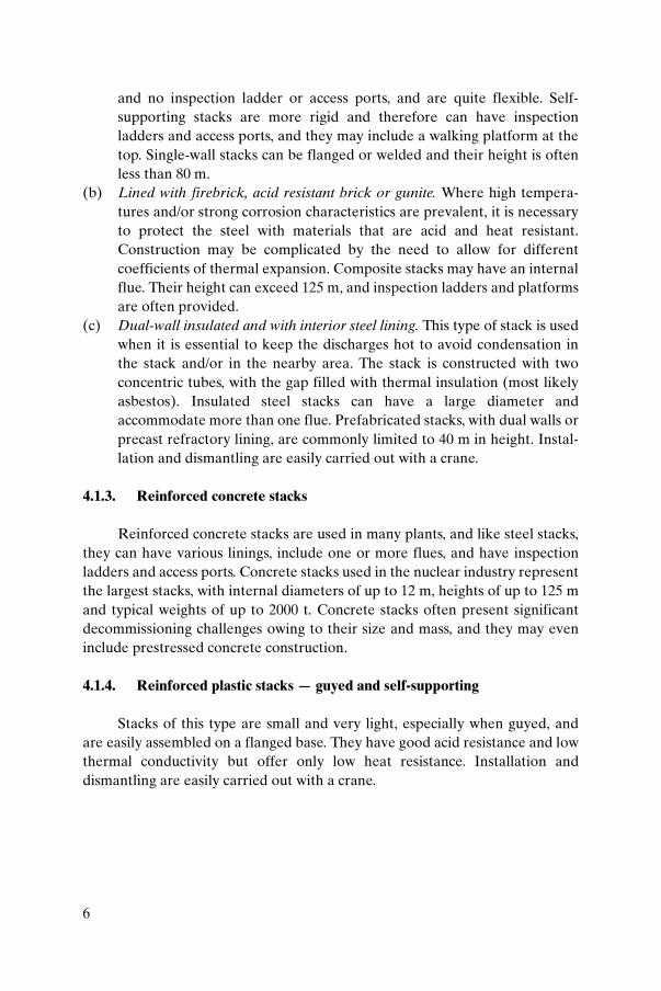
4.1.3. Reinforced concrete stacks
Reinforced concrete stacks are used in many plants, and like steel stacks,they can have various linings, include one or more flues, and have inspectionladders and access ports. Concrete stacks used in the nuclear industry representthe largest stacks, with internal diameters of up to 12 m, heights of up to 125 mand typical weights of up to 2000 t. Concrete stacks often present significantdecommissioning challenges owing to their size and mass, and they may eveninclude prestressed concrete construction.
4.1.4. Reinforced plastic stacks — guyed and self-supporting
Stacks of this type are small and very light, especially when guyed, andare easily assembled on a flanged base. They have good acid resistance and lowthermal conductivity but offer only low heat resistance. Installation anddismantling are easily carried out with a crane.

7
4.2. STACK DISMANTLING EXPERIENCE AT NON-NUCLEAR SITES
Around the world many companies have considerable experience in stackdismantling utilizing a broad range of methods and technologies to meetcustomer needs. A competitive market exists, and access to basic informationand experience is widely available. The demolition of non-nuclear stacksgenerally is less complex, is less expensive and can be accomplished in less timethan is the case for nuclear stacks. The dismantling techniques used at non-nuclear sites include:
— Wrecking ball;— Top-down breaking;— Explosives.
Dismantling with a wrecking ball is one of the oldest demolition systemsand the technique is still used.
Top-down breaking is shown in Fig. 3 for a concrete stack.Explosive techniques are used in both open and urban areas, and skilled
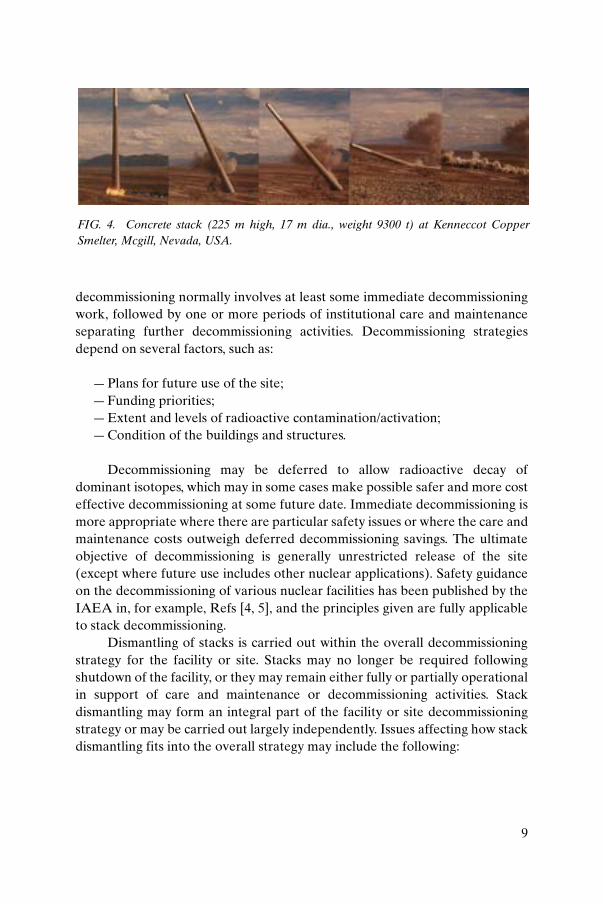
operators can direct a falling stack with an accuracy of 5°. The KennecottCopper Smelter concrete stack was felled (Fig. 4) using this technique. Thisstack was exceptionally large, measuring 225 m in height and weighing 9300 t.Demolition work took less than one week.
The explosive demolition of one of two stacks at the Italsider Bagnoliplant near Naples, Italy, is shown in sequence in Fig. 5. Each stack was 102 mtall and weighed 1250 t. The duration of the project was very short, requiringonly 10 person-days to demolish each stack.
An example of explosive demolition of a water tower structure, at theFernald site in the United States of America, is given in Ref. [3]. It may be ofrelevance since it has several features in common with stack dismantling.
5. NUCLEAR DECOMMISSIONING STRATEGIES
Nuclear facilities require decommissioning at the end of their operatinglife. The end of the operating life is reached for a variety of reasons, such ascompletion of planned work programmes, obsolescence, loss of funding orcompetition. Decommissioning strategies for redundant nuclear facilities varybut generally involve either immediate or deferred decommissioning(entombment being a strategy applicable to special cases). Deferred

8
FIG. 3. Brick lined concrete stack at Corus Steelworks, Port Talbot, United Kingdom.
9
decommissioning normally involves at least some immediate decommissioningwork, followed by one or more periods of institutional care and maintenanceseparating further decommissioning activities. Decommissioning strategiesdepend on several factors, such as:
— Plans for future use of the site;— Funding priorities;— Extent and levels of radioactive contamination/activation;— Condition of the buildings and structures.
Decommissioning may be deferred to allow radioactive decay ofdominant isotopes, which may in some cases make possible safer and more costeffective decommissioning at some future date. Immediate decommissioning ismore appropriate where there are particular safety issues or where the care andmaintenance costs outweigh deferred decommissioning savings. The ultimateobjective of decommissioning is generally unrestricted release of the site(except where future use includes other nuclear applications). Safety guidanceon the decommissioning of various nuclear facilities has been published by theIAEA in, for example, Refs [4, 5], and the principles given are fully applicableto stack decommissioning.
Dismantling of stacks is carried out within the overall decommissioningstrategy for the facility or site. Stacks may no longer be required followingshutdown of the facility, or they may remain either fully or partially operationalin support of care and maintenance or decommissioning activities. Stackdismantling may form an integral part of the facility or site decommissioningstrategy or may be carried out largely independently. Issues affecting how stackdismantling fits into the overall strategy may include the following:
FIG. 4. Concrete stack (225 m high, 17 m dia., weight 9300 t) at Kenneccot CopperSmelter, Mcgill, Nevada, USA.

10
FIG
. 5.
Exp
losi
ve d
ism
antli
ng s
eque
nce
at th
e It
alsi
der
Bag
noli
plan
t, N
aple
s, I
taly
.

11
(a) The need for the ventilation system changes after shutdown of a facilityand may decrease during decommissioning. The stack may be neededinitially but ventilation requirements will cease at some stage. Ventilationneeds during decommissioning are often provided for in situ (e.g. byventilated tents) or by new ventilation systems with discharge points atbuilding level.
(b) Stacks were designed to meet safety criteria at the time of constructionthat may be less stringent than those in use later on, leading to a decisionfor early dismantling. Modern standards are generally more demanding(e.g. seismic qualification) and may require assessment of events such ashigh winds, tornadoes or aircraft impact that may not have beenpreviously considered.
(c) Stacks were usually designed for a defined lifetime appropriate to that ofthe nuclear facilities serviced. Decommissioning strategies may extendthe life of the stack far beyond the original design lifetime.
(d) Deterioration of mechanical properties of the stack may result withageing. Natural forces (high winds, rain, acid fumes, earthquakes andtemperature variations) or mechanical vibration may reduce structuralstrength (through fatigue, erosion or corrosion) over extended lifetimes.Several publications have dealt with the long term deterioration ofnuclear facilities [6–10] and may be usefully consulted, but they do notspecifically address stacks. Ultimately a weakened stack presents anincreasing collapse hazard.
(e) The safety benefit of removing potential stack collapse hazards should becompared with the disadvantage of not having the stack available forfurther care and maintenance or decommissioning activities.
(f) Planned reuse of the site for nuclear or non-nuclear activities may requirea similar stack.
(g) Stakeholder perception can impact the stack decommissioning strategy,e.g. the end state and selection of dismantling methodology.
5.1. HAZARDS OF TAKING NO ACTION
Following the permanent shutdown of a nuclear facility, a hazardoussituation can eventually arise if no action is taken. A comprehensivedescription of various risks associated with a no-action strategy is given insection 3.3 of Ref. [11]. A policy of no action is generally not approved byregulators and is not recommended by the IAEA. Decommissioning impliespositive management action together with adequate resources and initiatives.

12
If stack dismantling is deferred, an appropriate level of refurbishment orupgrading may be required for longer term structural stability. Also, wheredeferred decommissioning of contaminated stacks is considered, some post-operational cleanup may be required. This may involve the removal of contam-ination from internal surfaces.
It should be noted that resistance against earthquakes and high winds is aserious issue even during plant operation. It was recently reported thatfollowing an inspection which revealed degradation in the stack’s tie-rods atCruas nuclear power plant (NPP), France, the French Nuclear Safety Authorityissued an order to the operator to make the necessary backfits by a certain date[12].
5.2. TECHNOLOGICAL CHALLENGES IN STACK DISMANTLING
Stack dismantling strategies need to optimize technical, safety, environ-mental and economic requirements within the overall facility/site decommis-sioning strategy. This challenge has resulted in the application of innovativetechnology and techniques such as:
(a) Remote decontamination systems, e.g. a robotically operated highpressure water jet or scabbling equipment to remove internal surfacelayers.
(b) Contamination management, e.g. by wetting, painting and the use ofstrippable coatings.
(c) Containment systems, including filtered extract and liquid collection.(d) Asbestos removal.(e) Use of mobile hydraulic crushers. For example, crushers weighing less
than 3 t can apply a force of up to 2000 kN to crush concrete up to 1 mthick.
(f) Combined cutting and lifting operations at elevated heights. (g) Use of vibration analysis and impact limiters for stack demolition by
explosive techniques. For example, sand or loose earth has been used asan impact limiter to reduce vibrations and detonation effects to a levelallowing these techniques to be used adjacent to other buildings.
Stack demolition can only truly be optimized by incorporating decommis-sioning requirements at the design stage. The challenge to future stackdesigners is to maximize the ease of dismantling without sacrificingperformance, economy or safety.

13
6. PRE-DISMANTLING CHARACTERIZATION
Accurate physical, chemical and radiological characterization is a keyfactor in the selection of stack dismantling strategies and technologies.However, the cost and risk of obtaining characterization data must be weighedagainst the risks resulting from the absence of this information. Physicalcharacterization determines parameters such as stack size, design andmaterials; concrete thickness; and corrosion or deterioration of components.These are essential elements for estimating the residual mechanical propertiesof the stack and the length of time the stack can safely remain in place. Smallfissures and cracks within the inner layers of a stack may indicate insufficientstructural integrity to withstand decontamination procedures. It should also benoted that many old stacks may lack fully comprehensive design and as-builtconstruction records, and pre-dismantling characterization can be useful inverifying the accuracy of records and filling any information gaps.
A significant consideration for stack decontamination is the finish ofinterior surfaces. For example, a coarse, porous surface will absorb contami-nation more readily and will be more difficult to decontaminate than a smooth,sealed surface.
Accessing a tall stack to obtain samples for physical or radiologicalcharacterization purposes requires careful consideration of industrial safety(for example with respect to scaffolding, cranes and confined spaces). Charac-terization activities in a contaminated environment will require radiologicalprotection provisions. Practical applications of these to stack decommissioningare given in Refs [13, 14]. For example, most stacks are designed with an accessport to provide entry to the interior. In order to minimize any potential releasedue to the opening of this port, a containment may be needed, e.g. a simplealuminium frame which supports a tent made of reinforced plastic sheeting[15]. It should also be noted that opening the access port in operating stacksmight disturb and disperse contamination. In some cases remote operationtechniques, such as videography [15] or even robots [14], have been proposedor deployed to overcome personnel access issues. Although remote or roboticcharacterization of stacks is often proposed, to date most stack characterizationwork has been done manually owing to the complexities of using these newtechnologies. It is expected that gamma cameras, i.e. systems for superimposinggamma radiation readings and spectrographic information onto visual imagesof an object, may be effective in radiological characterization of a stack [1,section 6.1.2]. Likewise, the use of the new In Situ Object Counting Systemisotopic identification device may prove useful in stack characterization, in

14
particular at radioactivity concentrations near clearance levels, a situation thatcommonly occurs in stack decommissioning [16].
For radiological characterization, it should be noted that in most caseslogbooks and reports regarding material released through a stack may beoutdated, incomplete or non-existent. In addition, there is no reliable way totell how much of the released material has been deposited and remains onstack walls. Stack characterization data provide information to determinewhether a stack can be decontaminated in a cost effective manner. The degreeof propagation of contaminants through the interior wall is another importantpiece of information, for example for assessing the amounts of radioactive andnon-radioactive (below clearance levels) waste generated by decontaminationor dismantling. While sampling the entire surface of a stack may be possible, itmay be time consuming and is not necessarily economical. Through applyingseveral assumptions and mathematical derivations, a good approximation ofpotentially contaminated areas can be achieved. By sampling or coring selectedareas, the entire stack can be characterized in a cost effective manner [15](Fig. 6). A number of publications describe radiological characterizationtechniques including statistical approaches, e.g. Refs [17–19]. Results of theradiological characterization of the stack at Garigliano NPP, Italy, are given inRefs [14, 20].
7. PRE-DISMANTLING DECONTAMINATION OPTIONS
Pre-dismantling decontamination is better considered within the contextof the overall dismantling strategy. The cost and risk of in situ decontaminationare typically evaluated relative to benefits of dismantling and decontaminationat ground level. There are three main pre-dismantling decontaminationoptions:
— Decontamination to unrestricted release levels or waste de-categorization in situ;
— Partial decontamination in situ;— No in situ decontamination, i.e. decontamination at ground level after
dismantling or direct disposal with no decontamination.
In situ decontamination may provide significant benefits by:
— Reducing occupational exposures;

15
— Reducing the residual radiation source at the site to minimize anypotential hazard to public health and safety (e.g. in preparation for safeenclosure);
— Achieving unrestricted release for the whole structure, simplifyingsubsequent dismantling and management of waste.
Conversely, one should consider that in situ decontamination mayproduce more secondary waste and may entail additional safety risks. A post-dismantling decontamination strategy may prove more cost effective andreduce overall worker exposure. A methodology for selecting between decon-tamination prior to dismantling or proceeding to direct dismantling ispresented in Section 10.
FIG. 6. Mound facility, USA. Stack core drilling at 20 ft (6 m) level opposite ventilationentry port.

16
7.1. DECONTAMINATION CRITERIA
Decontamination techniques are extensively dealt with in the technicalliterature [1, 18, 19]. For stacks, a typical problem is how to remove the surfacelayer where particulate contamination was deposited during operation. Thethickness of the material to be removed is important, because some activitymay have penetrated into deeper layers through cracks or fissures. Otherselection criteria for stack decontamination technologies include:
— The requirement to preserve structural integrity, e.g. in the case ofreinforcing bars close to the surface;
— Minimization of radiological and industrial safety hazards, e.g. by use ofremote systems;
— Simplicity, including the possibility for equipment retrieval in the event offailure;
— Containment during decontamination;— Containment of waste arisings;— Market availability and costs.
7.2. DECONTAMINATION TECHNIQUES
Typical techniques for removal of contaminated surface layers include:
— Cleaning with abrasives;— Use of high pressure water jets;— Grinding/shaving; — Scarifying/scabbling.
Abrasive cleaning uses a medium such as sand, plastic, glass or steelbeads, or grit, e.g. garnet, soda, aluminium oxide or CO2 ice pellets. Abrasivecleaning can be performed to remove fixed or loose contamination from metaland concrete surfaces. In the case of concrete surfaces, a significant amount ofthe base material is also removed. This process is most effective on flat surfacesbut can also be used for areas that are difficult to reach. This process producescomparatively large amounts of secondary waste. It can be carried out wet ordry, with the abrasive medium being blasted against a surface using water orcompressed air as the propellant [1, section 6.2.2.5]. A common application ofthis technology is sandblasting, which was carried out remotely to decontam-inate a stack at a fuel reprocessing pilot plant in the USA. The rotary sand–airblast head was lowered down the stack with a winch. Reverse stack ventilation

17
was employed to draw the dust created down the stack and into a largefibreglass and high efficiency particulate air (HEPA) filter system [21, 22].
High pressure water processes use a water jet to remove contaminationfrom surfaces. Pressures and flow rates are optimized for individual require-ments. Recirculation and treatment systems may be considered to reduce andhandle secondary waste water production. Since the use of water can result inthe concentration of contaminants, where fissile material is present, criticalityissues may be significant. Typical applications include the cleaning of inacces-sible or remote surfaces, making this technique generally applicable to stacks.In some cases grit is entrained in the water jet to enhance decontamination,making the process similar to the abrasive cleaning described above [1, section6.2.2.11]. One application using this process to decontaminate a stack is givenin Ref. [23]. This process can result in visibility problems in confined spaces.
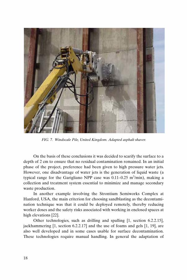
Grinding and shaving processes use coarse grained abrasives in the formof water cooled or dry diamond grinding wheels, or multiple tungsten carbidesurfacing discs. This process is recommended for use where only thin layers ofcontaminated material need to be removed. This type of decontamination hasbeen demonstrated for general application at Hanford C in the USA [1, section6.2.2.12] but is not proven for stack decontamination. An off-the-shelf asphaltroad shaver adapted for use in the decontamination of the Windscale Pile stackin the United Kingdom is shown in Fig. 7.
Scarifying and scabbling are used primarily on concrete surfaces toabrade and remove a contamination layer. Scarifiers and scabblers includepneumatically operated impact tools, needle guns and flap wheel type tools.These processes are relatively effective for removing a contaminated layerfrom the surface of concrete and in some cases metals, and a broad range ofindustrial equipment is now available [1, section 6.2.2.13]. Examples of the useof scabblers on floors and walks at the Japan Power Demonstration Reactor(JPDR) decommissioning project are shown in Fig. 8.
The decontamination project at Garigliano NPP, Italy (Fig. 9), is a casewhere a selection process resulted in preference being given to scarifyinginternal surfaces [20]. The radiological characterization described in Refs [14,20] concluded that:
— The activity concentration decreased with height.— The surface contamination level was less than 1 Bq/cm2 (the clearance level
adopted) above 41 m of stack height and at depths of greater than 1 cm.— The reinforcing bars were not contaminated.
18
On the basis of these conclusions it was decided to scarify the surface to adepth of 2 cm to ensure that no residual contamination remained. In an initialphase of the project, preference had been given to high pressure water jets.However, one disadvantage of water jets is the generation of liquid waste (atypical range for the Garigliano NPP case was 0.11–0.25 m3/min), making acollection and treatment system essential to minimize and manage secondarywaste production.
In another example involving the Strontium Semiworks Complex atHanford, USA, the main criterion for choosing sandblasting as the decontami-nation technique was that it could be deployed remotely, thereby reducingworker doses and the safety risks associated with working in enclosed spaces athigh elevations [22].
Other technologies, such as drilling and spalling [1, section 6.2.2.15],jackhammering [1, section 6.2.2.17] and the use of foams and gels [1, 19], arealso well developed and in some cases usable for surface decontamination.These technologies require manual handling. In general the adaptation of
FIG. 7. Windscale Pile, United Kingdom. Adapted asphalt shaver.

19
FIG. 8. JPDR decommissioning project. (a) Floor decontamination using a scabbler;(b) wall surface decontamination using a scabbler.
(a)
(b)

20
existing, proven, commercially available technology to meet decontaminationneeds is efficient and economical.
Emerging technologies that require additional development before theycould be considered as stack decontamination processes are listed below butare not given further treatment in this report.
— Light ablation (lasers) [1, section 6.2.4.1];— Microwave heating [1, section 6.2.4.2];— Flame attack [1, section 6.2.4.3];— Biodecontamination (of concrete) [1, section 6.2.4.4; 24];— Electrokinetics [1, section 6.2.4.5].
FIG. 9. Stack at Garigliano NPP, Italy.

21
8. DISMANTLING APPROACHES
8.1. DISMANTLING CRITERIA
In stack dismantling, the proximity of adjacent facilities is an importantelement to consider with respect to avoiding undue risk or disturbance.Containing waste materials and preventing the escape of contaminants are alsovital. An important factor relevant to the selection of a dismantling strategy isresidual contamination following any in situ decontamination. Additionalfactors include:
— Simplicity and ease of deployment of dismantling tools, taking intoaccount the availability of working areas around the stack (to deploycranes, scaffolding, lifts, etc.);
— Minimization of radioactive waste;— Ease of handling, treatment, transport, storage and disposal of waste
arisings (recycling of materials being a desirable option);— Desirability of using remotely operated equipment or robots for reasons
of radiological and industrial safety;— Minimization of radiological and industrial hazards, for example through
the use of remote systems;— Demands of scheduling and the duration of the work;— Availability of equipment, experience of the workforce, costs, etc.
8.2. DISMANTLING TECHNIQUES
Many established dismantling techniques are available, including:
— Top-down segmenting of the stack in horizontal slices or pieces;— Top-down breaking;— Controlled collapse;— Intact removal.
8.2.1. Top-down segmenting
Top-down segmenting comprises cutting the stack into large butmanageably sized sections and lifting and lowering these sections to groundlevel. Brick stacks are generally unsuitable for this approach (sections of brickstructure are not stable for lifting), and different techniques are used for steel

22
and concrete reinforced stacks. Top-down segmenting is particularly suitablefor stacks requiring post-dismantling decontamination at ground level. Thisapproach includes three main activities:
— Establishing safe working platforms;— Cutting operations;— Lifting operations.
Working platforms are required for workers to safely cut through thestack and to sling the section being released. Safe working platforms can beprovided by several means, including scaffolding (Fig. 10), mobile platforms(independent or attached to or suspended from the stack) (Fig. 11) and cranesuspended cages. One technique uses a special power shovel which climbs up tothe stack top on cables [25].
Cutting operations are required to separate a section of the stack fromthe main structure. Appropriate techniques depend upon the type of stackconstruction. Cutting techniques generally use established constructionindustry methods, including:
FIG. 10. Scaffolding used during dismantling of the stack of the Steam Generating HeavyWater Reactor, United Kingdom.

23
For steel stacks:
— Mechanical saws, shears, nibblers, etc.;— Flame or plasma cutting.
For concrete stacks:
— Concrete fragmentation, e.g. drilling and spalling, use of rock splitters(hydraulic wedges, expanding grout), use of jackhammers;
— Diamond wire sawing;— Circular diamond wheel sawing;— Thermic lances.
Concrete fragmentation techniques result in an amount of brokenconcrete that needs to be managed. This material can be dropped inside thestack, but measures are often necessary to prevent this material falling outside
FIG. 11. Stack at Windscale Pile 2, United Kingdom. External access platforms.

24
the stack. Steel reinforcing used in concrete generally needs to be cutseparately.
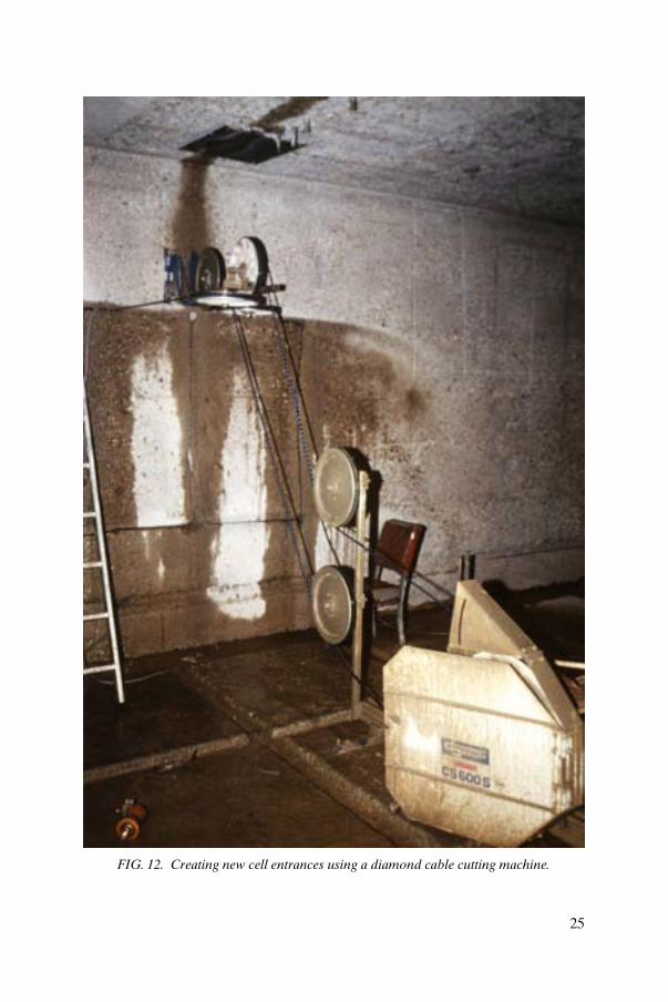
Diamond wire saws consist of diamond abrasives embedded in beads on asteel cable. Diamond wire sawing has been extensively used for cutting throughconcrete (including reinforcing bars) and masonry. Wire sawing was used todismantle the stack at the National Research Experimental Reactor in Canada[26], at Humboldt Bay NPP in the USA [27], and at the stack of the WinfrithSteam Generating Heavy Water Reactor (SGHWR) in the United Kingdom, asdescribed in Annex I.B. The technique has been applied to cut through heavilyreinforced concrete. Figure 12 shows an application of this technique.
The use of circular saws is another established technique employed to cutreinforced concrete. The saw blade is a steel disc with diamond embedded teethand can range in size up to 2 m in diameter. High reaction forces require theuse of robust deployment equipment such as that shown in Fig. 13.
Both diamond wire and circular sawing are generally wet cuttingprocesses resulting in potentially contaminated liquid waste. Diamond wirecutting can also be conducted using a dry approach, which eliminates theproduction of liquid waste [28].
Thermic lances consist of iron pipes packed with a combination of steel,aluminium and magnesium wires through which a flow of oxygen gas ismaintained. Cutting is achieved by a thermite reaction at the tip of the lance,which consumes the lance as cutting progresses. Lances vary in length fromabout 0.5 m to more than 3 m and have a range of diameters. Ignition of thelance is normally performed using a flame or electric arc. This technique maybe unsuitable in high contamination environments as a large amount of dust,aerosols and fumes can be created.
One interesting example of top-down segmenting was the workconducted in 2002 at the shut down Creys–Malville fast breeder reactor (Super-phénix) [29]. This activity involved 48 stacks. Fourteen main stacks were in usefor the cooling of sodium–air heat exchangers and 34 smaller stacks were usedfor building ventilation. These stacks were no longer required following plantshutdown and were dismantled in the early phases of decommissioning becauseof their high maintenance costs.
In total the project removed 950 t of steel, including:
— Fourteen main stacks ranging in weight from 3 to 25 t;— Smaller stacks, each weighing less than 3 t;— Piping located outside of the stack.
25
FIG. 12. Creating new cell entrances using a diamond cable cutting machine.

26
The length of the main stacks ranged between 23.5 and 35 m. They weresegmented into two or three pieces having a maximum weight of 8 t. The lengthof the smaller stacks was between 1.5 and 4.5 m. The work was carried out at anelevation of between 75 and 95 m. The stacks were radiologically clean.
A crane capable of lifting 50 t at a height of 120 m was used for thedismantling of the stacks. The segmenting was carried out by specializedworkers suspended by cables (Figs 14, 15). A maximum of 30 people worked onthe stack removal at any given time. Another project utilizing top-downsegmenting is detailed in Annex I.H. The backup approach for temporaryremoval of the stack at Gösgen NPP, Switzerland, was demonstrated by theremoval of a non-nuclear stack of a local district heating power plant. Theprocess utilized a climbing saw platform lowered into the stack to allowdiamond cutting of the stack into segments (Fig. 16).
8.2.2. Top-down breaking
Whereas top-down segmenting releases large sections for controlledlifting to ground level, top-down breaking involves breaking the stack intosmaller chunks of debris that are generally dropped inside the stack or down
FIG. 13. Concrete cutting using a diamond tipped blade saw.

27
FIG. 14. Creys–Malville, France. Removal of stack segments.

28
FIG. 15. Stack at Creys–Malville, France. Preparation for segmenting.

29
external chutes. This approach is particularly suitable for brick stacks whereexplosive collapse is not appropriate. It is most suitable for stacks that havebeen fully decontaminated (down to or approaching unrestricted releaselevels) and is generally unsuitable for highly contaminated structures, for whichradioactive waste minimization and contamination control pose significantdifficulty.
Breaking can be carried out manually or by mechanical techniques.Manual methods require safe working platforms and use mortar fragmentationtechniques to break up the stack structure, similar to the case of top-downsegmenting.
Mechanical techniques can be deployed by excavator mounted and cablesuspended systems, and include concrete pulverizers, rams, shears and grapples[18].
— Concrete pulverizers crush concrete and masonry, separating rebar andencased steelwork (using a range of interchangeable jaws).
— Rams demolish concrete structures (up to 2 m thick) using a chisel point.
FIG. 16. Gösgen NPP, Switzerland. Climbing saw inserted into the stack.
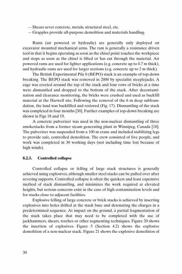
30
— Shears sever concrete, metals, structural steel, etc.— Grapples provide all-purpose demolition and materials handling.
Rams (air powered or hydraulic) are generally only deployed onexcavator mounted mechanical arms. The ram is generally a resistance driventool in that it begins operating as soon as the chisel point touches the workpieceand stops as soon as the chisel is lifted or has cut through the material. Airpowered rams are used for lighter applications (e.g. concrete up to 0.7 m thick),and hydraulic rams are used for larger sections (e.g. concrete up to 2 m thick).
The British Experimental Pile 0 (BEPO) stack is an example of top-downbreaking. The BEPO stack was removed in 2000 by specialist steeplejacks. Acage was erected around the top of the stack and four rows of bricks at a timewere dismantled and dropped to the bottom of the stack. After decontami-nation and clearance monitoring, the bricks were crushed and used as backfillmaterial at the Harwell site. Following the removal of the 6 m deep subfoun-dation, the land was backfilled and restored (Fig. 17). Dismantling of the stackwas completed in four months [30]. Further examples of top-down breaking areshown in Figs 18 and 19.
A concrete pulverizer was used in the non-nuclear dismantling of threesmokestacks from a former steam generating plant in Winnipeg, Canada [18].The pulverizer was suspended from a 100 m crane and included stabilizing legsto provide safe, controlled demolition. The crew consisted of five people, andwork was completed in 30 working days (not including time lost because ofhigh winds).
8.2.3. Controlled collapse
Controlled collapse or felling of large stack structures is generallyachieved using explosives, although smaller steel stacks can be pulled over aftersevering supports. Controlled collapse is often the quickest and least expensivemethod of stack dismantling, and minimizes the work required at elevatedheights, but serious concerns exist in the case of high contamination levels andfor stacks close to adjacent facilities.
Explosive felling of large concrete or brick stacks is achieved by insertingexplosives into holes drilled at the stack base and detonating the charges in apredetermined sequence. At impact on the ground, a partial fragmentation ofthe stack takes place that may need to be completed with the use ofjackhammers, shears, torches or other segmenting techniques. Figure 20 showsthe insertion of explosives. Figure 5 (Section 4.2) shows the explosivedemolition of a non-nuclear stack. Figure 21 shows the explosive demolition of

31
a nuclear stack at Hanford, USA. The stack was felled precisely into apreviously excavated trench. The collapsed structure was then covered overwith soil to natural grade level.
Systems for limiting impact to minimize flying debris hazards duringcollapse include vibration limiting structures (e.g. soil and sand heaps or‘pillows’) and barriers.
(a) (b)
(c)
(d)
FIG. 17. BEPO stack dismantling, United Kingdom. (a) Stack before dismantling;(b) working ‘cage’; (c) dismantling activity; (d) remediated site at the end of the disman-tling project.

32
FIG. 18. Mound facility, USA. Top-down breaking of a brick stack.

33
A large scale stack demolition operation using explosives to fell theMarcoule G1 stack, France, is detailed in Annex I.G. This project was unique inthat it addressed a very large stack constructed of prestressed concrete. For thisproject, directional control of the fall of the stack was critical to avoid damageto adjacent facilities. Figure 22 shows a time sequence of the fall of the G1stack.
8.2.4. Intact removal
Intact removal is often suitable for relatively short and/or light stacks.Such stacks are often constructed in sections, facilitating dismantling byreversing the construction sequence. This method may offer advantages interms of reduced radiation exposures, short duration of the work, andsimplicity, but may cause interference with surrounding buildings, involveextended work at height and require additional waste treatment for disposal.
The bolted sections in these stacks often used asbestos gaskets, and thishazard must be considered when dismantling them. The sections are normallysealed at both ends, cut or unbolted and lowered to the ground. In some casesthey can be removed and lowered in one piece. Where necessary, the inner
FIG. 19. Top-down breaking of a concrete stack, South Africa.

34
FIG. 20. Initial Engine Test (IET) stack at Idaho National Engineering and Environ-mental Laboratory (INEEL), USA. Insertion of explosives.

35
FIG. 21. Felling of the 110-F stack at Hanford, USA, using explosives.
FIG. 22. Time sequence of the stack fall at Marcoule G1, France.

36
surface of the stack in the vicinity of cuts is decontaminated before cutting.Removed sections can sometimes be sealed at each end and transported astheir own shipping container [31]. Intact removal of large components andrelated factors are described extensively in Ref. [32]. The 23 m tall exhauststack of the Janus reactor, USA, was removed by this method using a boom liftand a crane [33]. Figure 23 shows the intact removal of a building exhaust stackat Los Alamos National Laboratory, USA.
FIG. 23. Exhaust stack intact removal at Los Alamos National Laboratory, USA.

37
9. WASTE MANAGEMENT
Waste management is a significant factor in stack dismantling. Waste isgenerated throughout the process and includes the structural material of thestack itself and integral ancillary systems, as well as secondary waste arisingfrom decontamination, cutting and dismantling operations.
Stack structures can be massive and have the potential to generatesignificant amounts of radioactive waste during dismantling. Disposal of largevolumes of radioactive waste can be difficult, and disposal costs can exceeddismantling costs. There are strong economic reasons to minimize radioactivewaste and maximize the clearance of materials for reuse, recycling or conven-tional disposal. Planning for the management of this waste can be the dominantissue in deciding the dismantling strategy.
Stack dismantling can result in the generation of radioactive airbornedischarges and of liquid and solid radioactive waste. Infrastructure andprovisions should be available to collect, treat, condition, transport, dispose ofand discharge this waste as required.
9.1. AIRBORNE RADIOACTIVE DISCHARGES
Airborne discharges typically include particulate contamination andradioactive gases released during dismantling activities. During controlledstack collapse, particulate contamination may be released when the stack hitsthe ground. The key feature of airborne discharges is the open workingenvironment associated with stack dismantling, i.e. outside the controlledenvironment of a building. The potential for airborne discharges to result fromstack dismantling can be minimized by predecontamination. However, wherethis is not practical, appropriate provisions such as water mist sprays [21, 22],fogging, tents or local ventilation systems should be used to control airbornereleases and ensure that they are maintained within acceptable levels. Theseprovisions can be supplemented by contamination fixants such as strippablecoatings. Fogging was successfully used for a 75 m contaminated stack atHumboldt Bay NPP, USA [34]. Particular problems may exist for certainstacks, e.g. stacks contaminated with alpha emitters from nuclear fuel cyclefacilities [21, 22]. Safety guidance on the control of radioactive discharges,including discharge authorizations, is given in Ref. [35]. In this connection, thepotential for airborne releases to arise during stack dismantling that aredifferent from those during normal operation (e.g. particulates as opposed tonoble gases) may require ad hoc consideration.

38
9.2. LIQUID RADIOACTIVE WASTE
Liquid waste results from wet decontamination activities and cuttingoperations. In many cases stacks are not equipped for the collection, storageand treatment of liquid radioactive waste, and systems for these purposesshould be procured and installed prior to stack dismantling work. Liquid wastetreatment systems need to deal with suspended solids/slurries, contaminantsand chemicals, as appropriate to the specific application and in accordance withestablished liquid waste disposal routes.
9.3. SOLID RADIOACTIVE WASTE
Solid radioactive waste resulting from stack dismantling is likely to be thelargest radioactive waste stream. It includes structural materials and secondarydecontamination, cutting and dismantling waste. The key waste managementissue for stack dismantling is the optimization of solid waste disposal, usingdecontamination to minimize the volumes of solid radioactive waste and tomaximize the clearance of materials [2]. An important issue is the treatmentand processing of solid waste to meet transport and disposal requirements,including dimensional and weight constraints. Various options exist to size andpackage solid waste for disposal, for example in drums, boxes or customcontainers.
Consideration of alternative waste management strategies can be adetermining factor in the selection of the decommissioning approach. Forexample, where very low level waste disposal facilities exist (such as those inFrance), or where clearance criteria are in place, additional emphasis on wastesegregation can provide considerable cost savings. The cost for management ofwaste in these cases can be much lower, providing a motivation for additionaleffort and resources to be expended on characterization and decontamination,leading to reduced overall project cost.
Information currently exists regarding the processing of large sections ofmetal and concrete waste from nuclear facilities. Work has included thedevelopment of custom containers [36] and the conditioning of concrete debris[37]. There is considerable experience available on concrete recycling [38], andR&D is still active in this field [39–41]. An example of guidance on this subjectis included in Ref. [42].

39
10. SELECTION OF THE OPTIMUM DISMANTLING STRATEGY
To select the optimum dismantling strategy for a nuclear stack, factorsrelevant to decision making must be identified and evaluated. Key decisionmaking factors are:
— Waste management; — Radiological and industrial safety and environmental requirements;— Regulatory requirements (acceptability of strategy, end state release
requirements);— Stack design, construction and physical condition;— Operating history (e.g. routine contaminant deposition, accidental
deposits);— Access to stack, working environment (e.g. height, location, impacts on
other facilities);— Proximity to adjacent facilities;— Resource and equipment cost and availability;— Funding priorities;— Public concerns.
In selecting a dismantling strategy, each of these factors is crucial in termsof its impact on the conduct of the project in a safe, timely and cost effectivemanner that meets regulatory requirements. The following paragraphs presenta discussion of how individual factors may influence decision making.
Waste management can be a major factor in determining the dismantlingapproach and timing. For example, the availability of treatment and disposalfacilities for contaminated waste may lead to an immediate dismantlingstrategy. Conversely, where waste cannot be readily accommodated, it may bepractical to select a deferred strategy. The unavailability of waste disposalfacilities can also drive a more comprehensive decontamination strategy in anattempt to reduce the amount of waste requiring interim storage where earlydismantling is necessitated by other factors. On-site disposal of low levelradioactive waste or cleared material may be an option on certain sites,depending on local and regulatory acceptance. On many sites this is not an optionand more complex waste management issues may drive the dismantling strategy.
Radiological and industrial safety and environmental requirements canhave a large influence on the selection of stack dismantling strategies. Forexample, dismantling stacks having high radiation fields or large amounts ofloose contamination may require the adoption of special techniques and

40
equipment selected to minimize worker doses. Industrial safety hazards oftenoutweigh radiological risk in stack dismantling projects and require carefulassessment.
Regulatory requirements can significantly affect the selection of thedismantling approach. Some strategies may be unacceptable and difficult toapprove because of area safety and environmental concerns. For example, theselection of felling by explosives may raise concerns about impacts on adjacentbuildings. End state requirements may also influence the strategy. Anunrestricted release end state demands more rigorous decontamination to meetrelease criteria.
Stack design and construction also influence the selection of stackdismantling strategies. Large, massive concrete stacks will require a differentset of technologies and equipment than small diameter metal stacks. Thedismantling strategy should be selected to best match the physical andstructural requirements of the stacks. For example, explosive, crushing andsawing techniques are better suited to concrete or brick stacks, while thermal(torch) cutting techniques work better for metal stacks.
The operating history of a stack can greatly influence the selection ofdismantling strategies. For stacks where the operating history reveals little orno radioactive or chemical contamination, dismantling operations are straight-forward, and strategies can be selected accordingly. However, for stacks withhigh levels of radioactive or chemical contamination, strategies may involveaggressive predecontamination or alternatively require remote operation andtotal containment. In such cases, much more rigid controls are appropriate inpredecontamination and/or dismantling of the stack, in monitoring workerexposure and environmental releases, and in the packaging and disposal ofwaste. Where alpha contamination is present, more rigorous monitoring andcontamination control are required.
Proximity to adjacent facilities can have a large impact on the selection ofdismantling strategies, and stacks located near operational facilities aregenerally not candidates for explosive removal. These stacks must generally beremoved from the top down. Conversely, isolated stacks, particularly those thatare massive and easily decontaminated, are good candidates for explosiveremoval. As a general rule, dismantling activities should not interfere withongoing operations at a facility and should not impact other workers or theenvironment.
Funding priorities, budgets, resource availability and equipment costsmay influence the dismantling strategy and may eliminate some options. Forexample, the availability of certain resources, e.g. explosives experts or largecranes, may strongly influence the strategy selection.

41
Local community public relations may be of enhanced importance. Thestack may have become a site landmark and community symbol, and there maybe significant resistance to its removal. Additionally, the dismantling is a highlyvisible activity possibly involving innovative techniques (explosives) and theuse of extremely large lifting equipment (cranes capable of hoisting large loadsat significant heights). These factors can make necessary a comprehensivecommunications plan to address local sensitivities and safety concerns. Anexample of local use of a stack as a landmark is given in Ref. [43]. In this case an80 m high stack had been used in the past to aid navigation into a local harbouron Lake Michigan in the USA.
To select the most appropriate strategy, the above considerations must bereviewed and a series of key variables defined. These variables can then beranked according to their importance and due weighting can be given to each.One approach is to construct a quantitative scoring system for the factorspertinent to alternatives for a specific stack dismantling project, to identify theadvantages and disadvantages of each alternative and rank the options toarrive at an optimum strategy. More formal quantitative evaluation methods,such as cost–benefit analysis and multiattribute analysis are available. Adetailed presentation of such analysis techniques is given in Refs [32, 44, 45].However, the value of such formal assessment techniques may be limited,considering the number of variable parameters present in any individual stackdismantling project.
Whichever approach is selected, careful analysis of the variousparameters must be performed and documented. It should also be noted thatno matter how carefully the analysis is done, overriding requirements such asregulatory criteria may supersede other considerations and dictate the actualstrategy selected.
The following examples highlight the importance of the decision makingprocess in the selection of a dismantling strategy.
The dismantling strategy initially selected for one case (Garigliano NPP,Italy) was controlled collapse using explosives [46]. The decision for this initialstrategy selection was based on the following main factors:
— Available experience indicated that this strategy was reliable.— The project implementation was of short duration.— Dismantling activities were planned to be conducted at ground level,
minimizing industrial risks compared with those involved in working at aheight of about 100 m.
The strategy based on the use of explosives assumed that a few buildingsadjacent to the stack would be removed prior to stack dismantling. Plans

42
changed, and it appeared that new waste storage buildings would have to beconstructed, thus further reducing the safe space available for stack collapse.Owing to these factors, the strategy was changed to top-down segmenting [14,20].
Explosive collapse was also selected for the dismantling of a stack atHanford, USA, as described in Refs [21, 22]. In this case the strategy withstoodscrutiny and was implemented. Following decontamination, the stack interiorwas painted with a water based latex paint to stabilize any remaining contami-nation. Painting was accomplished remotely using a specially designedmanifold from an airless pump attached to the same carriage used forsandblasting. The demolition work included chipping out sections of the stackto establish hinge joints; drilling holes in the stack for the placement ofexplosives; erecting a blast shield around the base of the stack; and loading,firing and detonating explosives. The stack was dropped into an areasurrounded by 3 m high berms. These berms restricted flying debris caused bythe impact of the stack landing. Prior to demolition, a temporary water spraysystem was designed and installed to minimize and control the dust generatedwhen the stack hit the ground. Eventually the entire stack was covered with fillmaterial and disposed of in situ. Similar projects are described in Refs [47–49].Figure 21 shows the fall of a Hanford stack.
The decision making process followed to dismantle a stack at theSavannah River Site, USA, is described in Ref. [50]. Initially the preferreddemolition method was mechanical disassembly using conventional tools andtechniques. This required that personnel mechanically break the stack startingfrom the top while working from suspended or attached temporary workingplatforms. Initially explosive demolition was rejected in favour of mechanicaldisassembly because the former posed unmanageable safety risks. For example,proximity to a building where irradiated fuel was handled presented a majorproblem because parts of this building were located within the height range ofthe stack. A misdirected fall could have had serious consequences. One of themore significant arguments against explosive demolition was the lack oftechnical experience and familiarity of site personnel with this technique.
Ultimately the discovery of significant levels of tritium in the stack raisedquestions about using mechanical disassembly. Radiological protectioncontrols were needed, including measures to prevent the spread of contami-nation beyond the worksite. This new requirement significantly increased thecomplexity of the work. For example, the use of protective clothing to mitigatecontamination hazards introduced other safety concerns, such as limited vision,heat stress and decreased dexterity. This led to a re-evaluation and eventuallyto selection of the explosive dismantling technique. United States Departmentof Energy personnel and contractors assisted in solving associated issues such

43
as ground vibration, air blast and flying debris. Further details of this projectare given in Refs [50–53].
The criteria and factors in the decision making process for a dismantlingstrategy for the Windscale Pile stacks are described in Refs [54, 55]. Inparticular, Unit 1 was heavily contaminated as the result of a serious accident in1957. Preliminary studies identified three constraints on selecting thedismantling strategy:
(a) The unacceptability of using cranes, owing to space constraints and heightlimitations, and because of the potential for damage to adjacent nuclearstorage ponds and reprocessing plant from a dropped load or a cranetoppling;
(b) The need to use remotely operated equipment to decontaminate someareas of the structure to reduce radiation and contamination levels priorto personnel access, in accordance with the ALARA principle;
(c) The need to use contamination control measures to prevent the spread ofradioactive contamination from the working areas.
In the Windscale case it was necessary to construct primary andsecondary containments at the base of the stack prior to the base accessdoorway being cut into the stack. Ventilation was installed at the stack base andtop. The ventilation was introduced into the stack through diamond core drilledholes. After removal of the concentrator section from the top of the stack, theaperture was enclosed to complete the containment.
In the case of Gösgen NPP, Switzerland, the decision making process wasimpacted by the regulators, who could not accept an auxiliary stack for a longerperiod of continued full reactor operation during stack dismantling. The initialapproach developed for top-down breaking was abandoned in favour of employingthe latest technologies using diamond circular blade cutting to dismantle the stackby top-down segmenting. The project is described in Annex I.H.
Decision making for the Marcoule G1 stack in France also led to a changein the dismantling method. The original plan, to use conventional top-downsegmenting, was not approved by the regulator. An alternative plan usingexplosives was developed and approved, and led to successful felling of thestack. The project is documented in Annex I.G.

44
11. DISMANTLING OF ANCILLARY SYSTEMS
There are a number of ancillary systems associated with stacks, includingdrains, ventilation ducts, monitoring systems, etc. Where these systems form anintegral part of the stack, it is appropriate to dismantle them as part of the stackdismantling project. Ancillary systems that are outside the physical stackboundary are considered to be part of the overall facility or site decommis-sioning project.
The boundary and interfaces of the stack dismantling project need to beclearly identified and managed to ensure that ancillary systems and services areappropriately isolated and terminated prior to and following the dismantlingwork.
Temporary systems required for the dismantling work need to be appro-priately installed and connected to adjacent ancillary systems and services.Temporary systems also need to be removed at the end of the work withappropriate terminations.
Some ancillary systems may need to be maintained during the stackdismantling project, e.g. navigation lights. Temporary arrangements andcontrols may be needed as the height of the stack is reduced.
12. ORGANIZATIONAL AND MANAGERIAL ISSUES
In general the organizational and managerial aspects associated with astack dismantling project are not markedly different from those connected withcarrying out other nuclear decommissioning projects, and the documentationrequirements are essentially the same. Organization, planning andmanagement aspects of nuclear decommissioning projects are welldocumented [56, 57]. However, there are a number of considerations specific toa stack dismantling project that require attention, in particular the following:
(a) Although an organization may have considerable experience in nucleardecommissioning work, stack dismantling may represent a ‘first of itskind’ task. This may require seeking specialized expertise to managework in an exposed environment at great heights.
(b) The safety review system for a nuclear facility or site often focuses heavilyon nuclear safety. For stack dismantling, the conventional hazards oftenoutweigh the nuclear hazards, and the safety assessment processes may
45
have to be adapted to properly evaluate those hazards. An example of thehazards of working at extreme heights is documented in Ref. [58].
(c) The combination of skills needed for working at height with radioactivematerials will have to be addressed and may require specific training.
(d) Public relations may be important where a stack has become part of thelocal landscape, heightening sensitivity about its removal. The public mayalso have safety concerns about the actual removal project.
13. COSTS
Budgetary constraints are a significant factor in developing overallfacility decommissioning strategies. These constraints extend to thedevelopment of stack dismantling strategies. Stack dismantling costs are oftendominated by site specific issues that require evaluation before a clear projectcost can be established. Because of this, cost comparisons between stackdecommissioning projects can be misleading. The elements of cost for stackdismantling projects are broadly similar to those for decommissioning projectsin general (see, for example, Ref. [59]). The key factors influencing stackdismantling project costs include:
Site factors:
— Structure, size, height and type of stack;— Physical condition of stack;— Nature and level of contaminants;— Location of facility;— Proximity to adjacent facilities.
Management interfaces:
— Regulatory framework;— Safety and environmental requirements;— Availability of resources and suitable expertise;— End state criteria;— Stakeholder management issues.
Waste management:

46
— Availability of disposal/recycling routes;— Treatment, packaging and transport requirements;— Interim storage issues.
Site factors influence cost largely on the basis of safety issues. Forexample, where explosive dismantling can be used, it often provides thequickest and least expensive dismantling option. However, if there is a risk toadjacent facilities, this method is not appropriate and an alternative approachmust be selected. For remote locations the access to large equipment (cranes)may significantly increase cost.
Management cost influences are predominantly risk based. For example,failure to obtain the required regulatory approval can result in significantrework.
Waste management factors may dominate project cost where largeamounts of radioactive waste are unavoidable. Good waste managementpractice minimizes waste generation, maximizes reuse and recycling, avoidsmixed waste production, and minimizes the overall cost of radioactive wastetreatment and disposal. In general, where established radioactive wastetreatment and disposal routes exist, project costs can be accurately estimated.Where these routes are not available, waste management costs are moredifficult to predict, may have a greater influence and may dominate projectcost.
14. CONCLUSIONS
For this report an evaluation was made of the factors to be considered inplanning and implementing a dismantling project for nuclear facility stacks. Anumber of conclusions can be drawn from the evaluation, as follows:
(a) Virtually all nuclear facilities have ventilation stacks which must bedismantled as part of broad site and facility decommissioningprogrammes.
(b) Although contamination levels and contaminants vary, stacks subjectedto accidental releases may have high contamination levels.
(c) Dismantling experience with nuclear stacks is not extensive, butequipment and technologies are readily available from experience withindustrial stack projects (e.g. use of explosives, very large cranes) and

47
have been easily adapted and used in a number of countries to completenuclear stack dismantling projects.
(d) Industrial safety considerations usually outweigh the risks associated withradioactive contamination.
(e) Waste management, including release criteria, is an important factor indeveloping a nuclear stack dismantling project and is often a criticalfactor in the timing and cost of a project.
(f) Stack dismantling is a highly visible activity that can create a need for awell developed stakeholder communications programme in order toachieve public confidence, which in turn can also influence regulatoryrequirements.
REFERENCES
[1] INTERNATIONAL ATOMIC ENERGY AGENCY, State of the Art Tech-nology for Decontamination and Dismantling of Nuclear Facilities, TechnicalReports Series No. 395, IAEA, Vienna (1999).
[2] INTERNATIONAL ATOMIC ENERGY AGENCY, Methods for the Minimiza-tion of Radioactive Waste from Decontamination and Decommissioning ofNuclear Facilities, Technical Reports Series No. 401, IAEA, Vienna (2001).
[3] WAGNER, J., Changing the Fernald skyline, Radwaste Solutions 55 (2003) 36–41.[4] INTERNATIONAL ATOMIC ENERGY AGENCY, Decommissioning of
Nuclear Power Plants and Research Reactors, IAEA Safety Standards SeriesNo. WS-G-2.1, IAEA, Vienna (1999).
[5] INTERNATIONAL ATOMIC ENERGY AGENCY, Decommissioning ofMedical, Industrial and Research Facilities, IAEA Safety Standards SeriesNo. WS-G-2.2, IAEA, Vienna (1999).
[6] INTERNATIONAL ATOMIC ENERGY AGENCY, Safe Enclosure of ShutDown Nuclear Installations, Technical Reports Series No. 375, IAEA, Vienna(1995).
[7] INTERNATIONAL ATOMIC ENERGY AGENCY, Safe Enclosure of NuclearFacilities During Deferred Dismantling, Safety Reports Series No. 26, IAEA,Vienna (2002).
[8] EUROPEAN COMMISSION, Intégrité à long terme des bâtiments et dessystèms (Long Term Integrity of Buildings and Systems), EUR 9928, EC, Brussels(1985) (in French).
[9] EUROPEAN COMMISSION, Degradation of Building Materials over a LifeSpan of 30–100 Years, EUR 10020, EC, Brussels (1985).
[10] EUROPEAN COMMISSION, Long Term Performance of StructuresComprising Nuclear Power Plants, EUR 12758, EC, Brussels (1990).

48
[11] INTERNATIONAL ATOMIC ENERGY AGENCY, Decommissioning of SmallMedical, Industrial and Research Facilities, Technical Reports Series No. 414,IAEA, Vienna (2003).
[12] Regulator gives EDF deadline for securing plant stacks, Nucleonics Week (10April 2003).
[13] TYMONS, B.J., COLQUHOUN, A.P., “Health physics problems associated withthe decommissioning of unconventional nuclear structures”, Proc. Int. Conf. onDecommissioning Offshore, Onshore and Nuclear Works, Manchester, UK, 1988,Thomas Telford, London (1988) 264–267.
[14] ENTE NAZIONALE ENERGIA ELETTRICA, Centrale Elettronucleare delGarigliano, Caratterizzazione Radiologica del Camino (Radiological Characteri-zation of the Stack), ENEL internal report, Doc-ENEL-SGN-GAR-FS/MAN-15-98, 1998, available from SOGIN, Rome (in Italian).
[15] PROFFITT, T.H., ROBERTSON, J.P., “The derivation and implementation of acost effective method to characterize an exhaust stack contaminated with radioac-tive constituents”, Waste Management ’92 (Proc. Symp. Tucson, 1992), WasteManagement Symposia, Tucson, AZ (1992) 1543–1544.
[16] UNITED STATES DEPARTMENT OF ENERGY, ISOCS for Free Release,Summary Rep. DOE/EM-0618, USDOE, Washington, DC (2001).
[17] INTERNATIONAL ATOMIC ENERGY AGENCY, Radiological Characteriza-tion of Shut Down Nuclear Reactors for Decommissioning Purposes, TechnicalReports Series No. 389, IAEA, Vienna (1998).
[18] UNITED STATES DEPARTMENT OF ENERGY, DecommissioningHandbook, Rep. DOE/EM-0142P, USDOE, Washington, DC (1994).
[19] EUROPEAN COMMISSION, Handbook on Decommissioning of NuclearInstallations, EUR 16211, EC, Brussels (1995).
[20] SOGIN, Sintesi del RPP Realizzazione di un Nuovo Punto di Scarico degliEffluenti Aeriformi per le Attivitá di Decommissioning e Abbattimento Camino(Project Report Summary on Implementation of a New Airborne EffluentDischarge Facility for Decommissioning Activities and Stack Dismantling), Rep.GR-GA-0013 (2004), available from SOGIN, Rome (in Italian).
[21] SPEER, D.R., “Decontamination and decommissioning of a fuel reprocessingpilot plant: a progress report”, International Decommissioning Symposium (Proc.Int. Symp. Pittsburgh, 1987), CONF-871018, Vol. 2, USDOE, Washington, DC(1987) IV-44–IV-57.
[22] LOUIE, R.L., SPEER, D.R., Decommissioning a 60-m tall exhaust stack, Nucl.Technol. 86 (1989) 120–127.
[23] WAITE, T., “Decontamination of the ICPP main stack”, Proc. Mtg San Diego,CA, 1993, Trans. Am. Nucl. Soc. 68 (1993) 59.
[24] HAMILTON, M.A., et al., “Biodecontamination: Cost/benefit analysis of a novelapproach for decontamination of massive concrete structures”, Nuclear Decom-missioning ’98 (Proc. Int. Conf. London, 1998), Professional Engineering, London(1998) 123–130.

49
[25] MB SPEZIALABBRUCH GmbH, New Method — Demolition of IndustrialChimneys and Other Reinforced Concrete Buildings, brochure, available fromMB Spezialabbruch GmbH, Schachen 29, Ottobeuren, Germany.
[26] BRAZIER, P., “Decommissioning of the NRX stack”, Decontamination andDecommissioning (Proc. Int. Symp. Knoxville, 1994), USDOE, Washington, DC(1994).
[27] BLUEGRASS CONCRETE CUTTING, INC., Humboldt Bay Nuclear PowerPlant Stack Removal by Diamond Wire Saw (2000), available from BluegrassConcrete Cutting, Inc., 107 Mildred St., P.O. Box 367, Greenville, AL 36037, andwww.concreteshaver.com, www.concretecutters.com
[28] PRAXL, H., “Report on dismantling and decontamination activities in the mainprocess building in the WAK plant”, KONTEC 2005 (Proc. 7th Int. Symp. onConditioning of Radioactive Operational and Decommissioning Wastes, Berlin,2005), Kerntechnische Gesellschaft, Berlin (2005).
[29] CENTRALE DE CREYS–MALVILLE, La déconstruction des cheminées (TheDismantling of the Stacks), Dossier de presse, Électricité de France (2002) (inFrench).
[30] UNITED KINGDOM ATOMIC ENERGY AUTHORITY, Harwell ProjectProfiles, BEPO, UKAEA (2003), www.ukaea.org.uk/reports/generalpdf/BEPO.pdf
[31] SCHNEIDER, K.J., et al., Technology, Safety and Costs of Decommissioning aReference Nuclear Fuel Reprocessing Plant, Rep. NUREG-0278, Battelle PacificNorthwest Lab., Richland, WA (1977) 7–45.
[32] INTERNATIONAL ATOMIC ENERGY AGENCY, Design and Constructionof Nuclear Power Plants to Facilitate Decommissioning, Technical Reports SeriesNo. 382, IAEA, Vienna (1997).
[33] FELLHAUER, C.R., “Janus reactor D&D project”, ICONE-6 (Proc. 6th Int.Conf. on Nuclear Engineering, San Diego, 1998), American Soc. of MechanicalEngineers, New York (1998) paper 142.
[34] ENCAPSULATION TECHNOLOGIES, Success Stories (2002),www.fogging.com/humboldt.html
[35] INTERNATIONAL ATOMIC ENERGY AGENCY, Regulatory Control ofRadioactive Discharges to the Environment, IAEA Safety Standards Series No.WS-G-2.3, IAEA, Vienna (2000).
[36] EUROPEAN COMMISSION, Large Packages for Reactor DecommissioningWaste, EUR 13345, EC, Brussels (1991).
[37] EUROPEAN COMMISSION, Immobilization of Active Concrete Debris UsingSoluble Sodium Silicates, EUR 13019, EC, Brussels (1991).
[38] INTERNATIONAL UNION OF TESTING AND RESEARCH LABORATO-RIES FOR MATERIALS AND STRUCTURES (RILEM), Demolition andReuse of Concrete and Masonry (Proc. 3rd Int. Symp. Odense, 1993), E&FNSpon, London (1994).
[39] EUROPEAN COMMISSION, Recycling of Activated/Contaminated Reinforce-ment Metal in Concrete, EUR 15045, EC, Brussels (1994).

50
[40] NUCLEAR REGULATORY COMMISSION, Microbial-Influenced CementDegradation — Literature Review, Rep. NUREG/CR-5987, EGG-2695, NRC,Washington, DC (1993).
[41] EUROPEAN COMMISSION, Radiologische Aspekte bei der Rezyklierung vonBetonschutt aus der Stillegung Kerntechnischer Anlagen (Radiological Aspectsin the Recycling of Concrete Rubble from the Decommissioning of NuclearInstallations), EUR 16703, EC, Brussels (1995) (in German).
[42] AMERICAN SOCIETY FOR TESTING AND MATERIALS, Standard Guidefor Evaluating Disposal Options for Concrete from Nuclear Facility Decommis-sioning, Standard Guide E-2216, ASTM, West Conshohocken, PA (2002).
[43] Big Rock Point is being dismantled, Mlive.com, 14 October 2004, www.mlive.com/business
[44] WATSON, S.R., HAYWARD, G.M., A Review of Some Formal Methods forDecision-Making, Rep. CVED/F CANS/TR 28, Cambridge Univ., UK (1981).
[45] LOUGH, W.T., JOHNON, W.R., WHITE, K.T., “A multi-criteria decision aid forevaluating nuclear power plant decommissioning”, International Decommis-sioning Symposium (Proc. Int. Symp. Pittsburgh, 1987), CONF-871018, Vol. 1,Natl Technical Information Service, Springfield, VA (1987) II-315–II-323.
[46] ENTE NAZIONALE ENERGIA ELETTRICA, Centrale Elettronucleare delGarigliano, Demolizione Controllata del Camino, Progetto di Massima(Garigliano NPP, Controlled Demolition of the Stack, Preliminary Plan), ENELinternal report, Doc-ENEL-GIN/GAR-13-DR, 1992, available from SOGIN,Rome (in Italian).
[47] STOLL, F.E., BOHRER, H.A., VOLDNESS, C.M., “Decontamination anddecommissioning of the Initial Engine Test Facility”, International Decommis-sioning Symposium (Proc. Int. Symp. Pittsburgh, 1987), CONF-871018, Vol. 1,Natl Technical Information Service, Springfield, VA (1987) III-237–III-253.
[48] BERTA, G., PIETRA, W., Microesplosione controllata per la demolizione di unaciminiera (Controlled micro-explosion for the demolition of a chimney), Quarryand Construction (Aug. 1995), PEI, Parma, Italy.
[49] Hanford reactor stacks demolished, D&D Monitor (31 August 1999) 14.[50] RIMANDO, R.V., DOWD, A.S., “Demolishing a tritium-contaminated exhaust
stack amid an operating nuclear area”, X-Change 1997: The Global D&DMarketplace (Proc. Conf. Miami, 1997), Hemispheric Center for EnvironmentalTechnology, Miami, FL (1998).
[51] UNITED STATES DEPARTMENT OF ENERGY, Understanding TritiumDuring Decommissioning, Rep. DOE/SR-5000-513, USDOE, Washington, DC(1997).
[52] UNITED STATES DEPARTMENT OF ENERGY, A Commercial Approach toIntegrated Safety Management: Decommissioning a Savannah River Site TritiumFacility, Rep. DOE/SR-5000-508, USDOE, Washington, DC (1997).
[53] UNITED STATES DEPARTMENT OF ENERGY, Tritium Facility Decommis-sioning: Pioneering Success at the Savannah River Site, Rep. DOE/SR-5000-510,USDOE, Washington, DC (1997).

51
[54] SHIELL, A.E., “Planning and management of Stage 1 dismantling of B16 Pilechimney, Sellafield”, Proc. 2nd Int. Conf. on Decommissioning Offshore, Onshoreand Nuclear Works, Manchester, UK, 1990, Thomas Telford, London (1990) 147–155.
[55] WRIGHT, E.M., “Remote dismantling of the Windscale Pile chimneys”, NuclearDecom ’92 (Proc. Int. Conf. on Decommissioning of Radioactive Facilities, 1992),Inst. of Mechanical Engineers, London (1992) 203–208.
[56] INTERNATIONAL ATOMIC ENERGY AGENCY, Planning and Managementfor the Decommissioning of Research Reactors and Other Small Nuclear Facili-ties, Technical Reports Series No. 351, IAEA, Vienna (1993).
[57] INTERNATIONAL ATOMIC ENERGY AGENCY, Organization and Manage-ment for Decommissioning of Large Nuclear Facilities, Technical Reports SeriesNo. 399, IAEA, Vienna (2000).
[58] TRADES UNION CONGRESS, Man dies in 350 ft plunge at Sellafield nuclearplant, Risks 89 (18 January 2003), www.tuc.org.uk
[59] OECD NUCLEAR ENERGY AGENCY, INTERNATIONAL ATOMICENERGY AGENCY, EUROPEAN COMMISSION, Nuclear Decommissioning— A Proposed Standardised List of Items for Costing Purposes, OECD/NEA,Paris (2000).

.

53
Annex I
EXAMPLES OF NATIONAL EXPERIENCE
The examples provided in this annex address a wide range of technicaland organizational aspects of stack decommissioning. This information isintended to provide practical guidance based on how stack decommissioningprojects are planned and managed in various countries. The examples given arenot necessarily best practices; rather they reflect a wide range of nationallegislation and infrastructure, site conditions and nuclear programmes.Although the information presented is not intended to be exhaustive, thereader is encouraged to evaluate the applicability of these schemes to a specificstack decommissioning project.

54
Annex I.A
CANADIAN EXPERIENCE OF STACK DISMANTLING
I.A–1. INTRODUCTION
Since 1990, Atomic Energy of Canada Ltd (AECL), a Government ofCanada Crown Corporation, has completed two nuclear facility ventilationstack decommissioning projects to meet facility and/or laboratory operatingneeds for reactors in the initial phases of decommissioning. The first projectwas conducted in 1991, addressing the complete removal of the redundantNRX reactor ventilation stack that had been isolated from the reactor in the1950s following an accidental contamination incident.
The second project, also carried out in 1991, involved the heightreduction of the Whiteshell Reactor 1 (WR-1) stack, which consisted of aventilation stack combined with an emergency cooling water supply tanklocated at the top of the structure. The project activities are outlined separatelyfor each project in the following sections.
I.A–2. NRX VENTILATION STACK REMOVAL
The NRX reactor ventilation stack was removed from service in 1952following a contamination release incident which resulted in deposition offission products on the inside surface of the stack. The stack was isolated fromthe reactor and sealed at the top with a steel cap, and it remained in that stateuntil decommissioning was undertaken in 1991.
The stack was 60 m in height and was constructed of reinforced concreteerected on a 1.7 m thick base slab approximately 8.5 m wide. The outsidediameter was 3.4 m at the base, with a wall thickness of 0.4 m, tapering to anoutside diameter of 1.5 m at the top, with a wall thickness of 0.1 m.
A radiation survey conducted prior to dismantling confirmed the resultsof an earlier survey indicating 137Cs to be the primary contaminant (in concrete),in the range of 50 000 Bq/g. The surveys also indicated alpha contamination,mainly from plutonium, at a level of 100 Bq/g, and beta contamination at a levelof 18 000 Bq/g.

55
I.A–2.1. Selection of removal method
Pre-decommissioning planning placed emphasis on the health and safetyof the workers and the public, as well as on protection of the environment,throughout the dismantling project, incorporating the following principles:
— Compliance with the ALARA principle;— Minimization of exposure to radiological and industrial hazards;— Achievement of a safe end state for any remaining structure or systems at
the end of the project.
Three approaches to dismantling were evaluated in the removal methodselection process, namely:
— Rubble the stack in an as-is condition;— Decontaminate in situ and then rubble;— Dismantle in sections and remove from the site for decontamination.
The sectioning followed by removal to a work location for decontami-nation was selected since this approach resulted in the earliest unrestrictedrelease of the site for other uses and provided better control over, and moretime for, the decontamination process.
The key work packages identified were:
— Painting of the bottom 3 m of the stack interior surface;— Assembling access scaffolding;— Removing the stack cover seal; inspecting, monitoring and removing
loose contamination from the interior surface;— Painting the interior surface at the cut locations;— Setting up crane operations;— Cutting stack sections and transporting them to the waste management
area;— Sectioning and removal of the foundation pad;— Clearing the site for turnover to the site owner.
A work plan was prepared for each work package, detailing the individualwork steps and the personnel and qualifications required. Safety requirementswere also detailed in each work plan. The work was carried out by a contractor.
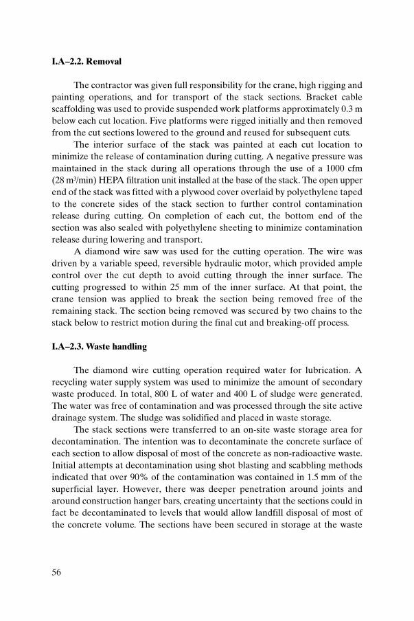
56
I.A–2.2. Removal
The contractor was given full responsibility for the crane, high rigging andpainting operations, and for transport of the stack sections. Bracket cablescaffolding was used to provide suspended work platforms approximately 0.3 mbelow each cut location. Five platforms were rigged initially and then removedfrom the cut sections lowered to the ground and reused for subsequent cuts.
The interior surface of the stack was painted at each cut location tominimize the release of contamination during cutting. A negative pressure wasmaintained in the stack during all operations through the use of a 1000 cfm(28 m³/min) HEPA filtration unit installed at the base of the stack. The open upperend of the stack was fitted with a plywood cover overlaid by polyethylene tapedto the concrete sides of the stack section to further control contaminationrelease during cutting. On completion of each cut, the bottom end of thesection was also sealed with polyethylene sheeting to minimize contaminationrelease during lowering and transport.
A diamond wire saw was used for the cutting operation. The wire wasdriven by a variable speed, reversible hydraulic motor, which provided amplecontrol over the cut depth to avoid cutting through the inner surface. Thecutting progressed to within 25 mm of the inner surface. At that point, thecrane tension was applied to break the section being removed free of theremaining stack. The section being removed was secured by two chains to thestack below to restrict motion during the final cut and breaking-off process.
I.A–2.3. Waste handling
The diamond wire cutting operation required water for lubrication. Arecycling water supply system was used to minimize the amount of secondarywaste produced. In total, 800 L of water and 400 L of sludge were generated.The water was free of contamination and was processed through the site activedrainage system. The sludge was solidified and placed in waste storage.
The stack sections were transferred to an on-site waste storage area fordecontamination. The intention was to decontaminate the concrete surface ofeach section to allow disposal of most of the concrete as non-radioactive waste.Initial attempts at decontamination using shot blasting and scabbling methodsindicated that over 90% of the contamination was contained in 1.5 mm of thesuperficial layer. However, there was deeper penetration around joints andaround construction hanger bars, creating uncertainty that the sections could infact be decontaminated to levels that would allow landfill disposal of most ofthe concrete volume. The sections have been secured in storage at the waste

57
management site pending future evaluation and possible additional decontam-ination before final disposition.
I.A–3. WR-1 STACK HEIGHT REDUCTION
The second project involved the WR-1 stack, which was a combinedventilation stack and emergency cooling water storage tank. It consisted of a45.7 m high by 2 m diameter ventilation column with an 8.4 m spherical waterstorage tank (263 000 L capacity) surrounding the upper section of thestructure. The stack was constructed from carbon steel plate, insulated withrigid non-asbestos insulation and covered with an aluminium outer jacket. Theinside of the stack column contained three water supply lines routed to andfrom the water storage tank.
With the shutdown of WR-1 in 1985, the emergency cooling water tankwas no longer required. Although the ventilation stack component mustremain in operation to meet the decommissioning plans for the reactor,removal of the stored water was carried out following reactor shutdown toreduce operating costs. The stored water required heating during the winter,adding a substantial burden to the decommissioning cost.
Following draining of the tank, it became apparent that the stack becameunstable in high winds owing to vortex shedding under reduced massconditions. Stability was re-established by refilling the tank with water, whichagain entailed a high annual operating cost. Ultimately the decision wasreached to remove the upper tank portion of the stack to eliminate the waterstorage cost. Studies concluded that the height reduction from 45.7 to 30.4 mwas acceptable for meeting the operational ventilation needs for WR-1 duringdecommissioning and planned deferment periods.
I.A–3.1. Tank removal plan
The work steps to remove the upper tank section of the stack consisted of:
— Recalculation of the stack release limits to confirm that environmentalrelease limits were not impacted by the reduced height;
— Guying the tower to maintain stability during removal operations;— Removal of aluminium cladding and insulation at all cutting locations;— Cutting off internal water pipes and electrical cables to the stack aircraft
obstruction lights;— Removal of the tank and stack sections and lowering them to the ground;

58
— Salvaging the top 2 m of the stack (outlet pipe section) for capping thestack at the reduced height;
— Restoring the aluminium cladding to its original condition for theremaining stack;
— Reconnecting the aircraft obstruction lights at the top of the stack;— Decontamination and disposal of the stack and tank components.
A radiation survey of the interior stack surfaces revealed very low levelsof contamination, indicating that lowering the stack sections to an adjacent lay-down area was adequate to control any possibility of contamination dispersion.The removal work was contracted out to Dominion Bridge, a crane company,with work carried out under AECL project management. A schematic of theheight reduction plan is given in Fig. I.A–1.
Water Tank
Ventilation Intakes
Bldg 100(WR-1)
WR-1 VENTILATION STACK and WATER STORAGE TANK
Section of Stack Removed
Reduced Stack Height
Bldg Extension
FIG. I.A–1. Schematic of the WR-1 stack height reduction plan.

59
I.A–3.2. Height reduction
The height reduction operation was a specialized large scale dismantlingactivity accomplished by the contractor through the use of two cranes: a 30 tcrane to raise and lower person-lifts to allow access to the tank for segmenting,and an 80 t crane to lower cut segments to the ground. The tank was removedin four sections as follows:
— The upper ventilation stack section, including an access platform at thetop, was cut off immediately above the water tank.
— The upper half of the water tank was torch cut from the lower portion andremoved (Fig. I.A–2).
— The internal ventilation pipe section was removed.— The lower half of the tank was cut free and removed along with a section
of the lower ventilation stack (Fig. I.A–3).— The upper ventilation stack section, including the access platform,
removed as the first step, was then reattached to the top of the remainingstack column to provide a remaining stack operating height of 30.4 m.
The ventilation stack was returned to normal operation to meet the needsof the WR-1 reactor decommissioning programme; it is to remain in operationduring a planned deferment period which is expected to extend to about 2040.
I.A–3.3. Waste handling
The sections of the water tank and the stack column were collected in alocal lay-down area for survey and decontamination as the project progressed.The water tank material was free of contamination and was shipped off-site forrecycling. The stack sections revealed some low level contamination during theradiation survey. These sections were decontaminated to clearance criteria andwere then disposed of in an on-site non-radioactive landfill.
I.A–4. CONCLUSIONS
These ventilation stack projects were both completed successfully to meetongoing AECL laboratory site requirements. The NRX stack removal met siteneeds by releasing space required for a new development project. The WR-1stack height reduction met the continued need for a facility stack during thereactor decommissioning programme while significantly reducing the cost ofcontinuing operation.

60
FIG. I.A–2. Removal of the upper half of the water tank.

61
FIG. I.A–3. Removal of the lower half of the water tank.

62
Annex I.B
DECOMMISSIONING THE SGHWR STACK
I.B–1. INTRODUCTION
The Steam Generating Heavy Water Reactor (SGHWR) was a 300 MW(th)prototype power reactor operated at Winfrith in the United Kingdom between1967 and 1990. The SGHWR stack was used to discharge filtered air from thereactor secondary containment from the mid-1960s until 1999.
The SGHWR stack was decommissioned to reduce the visual impact ofthe SGHWR facility. The stack was the highest structure on the facility, indeedon the Winfrith site. A schematic of the stack is shown in Fig. I.B–1, and viewsof the SGHWR facility are included as Fig. I.B–2. Views of the stack duringconstruction are included as Fig. I.B–3, and views of the stack prior to decom-missioning are shown in Fig. I.B–4.
I.B–2. DESCRIPTION
The SGHWR stack was constructed from reinforced concrete with acentral stainless steel flue. The stack was 120 ft (36.6 m) high and extended afurther 24 ft (7.3 m) below ground. The internal diameter was 6 ft 6 in (2.0 m),and the wall thickness was 1 ft 2 in (0.35 m) at the base (up to 10 ft (3.0 m)above ground level) and 9 in (0.23 m) for the remainder.
The stainless steel flue was 1 ft 9 in (0.53 m) in diameter and wascentralized by six steel spiders. A steel soot and access chamber for the flue waslocated at ground level and was supported by a profiled reinforced concretesupport beam.
The stack was internally contaminated with radioactive surface contami-nation, and in addition tritium was absorbed into the bulk concrete. Surfacecontamination resulted from any particulate contaminants that were notcaptured by the HEPA filters and carbon beds. Tritium contaminationabsorbed into the concrete resulted from the legal discharge of tritium over thelife of the reactor. The HEPA filters and carbon beds did not capture tritium.
The stack was internally monitored for surface contamination, andreadings of up to 34 Bq/cm2 were recorded. The predominant isotopes of thesurface contamination were 137Cs and 60Co. A sample of concrete chipped offthe inside surface of the concrete at the base of the stack was analysed for

63
16 ft dia.(4.9 m)
6 ft 6 in dia.(2 m)
CUT 1
15 ft
(4.6
m)
CUT 2
CUT 3
CUT 4
CUT 5
CUT 6
120
ft (3
6.6
m)
17 ft
(5.2
m)
SOOT ANDACCESSCHAMBER
HORIZONTAL FLUE
GROUND LEVEL
SGHWR SOUTHANNEX
BOILER HOUSE
SPIDER
INNER FLUE
FIG. I.B–1. Diagram of the SGHWR stack.

64
FIG. I.B–2. Views of SGHWR.

65
FIG. I.B–3. SGHWR stack during construction.

66
FIG. I.B–4. SGHWR stack before decommissioning.

67
tritium. A reading of 5.79 Bq/g was recorded. Tritium analysis of cores taken atground level gave maximum readings of 15.9 Bq/g, with peak readings locatedabout 2 in (0.05 m) from the inside surface.
Asbestos gaskets and joinings were present between connections on theinner steel flue and soot box on the stack.
I.B–3. PROJECT STRATEGY
I.B–3.1. Project definition
The SGHWR stack decommissioning project was defined as:
— Dismantling of the reinforced concrete structure of the stack to groundlevel in large undisturbed sections;
— Surface decontamination of the concrete sections to clearance levels foron-site storage;
— Dismantling of the soot box and flue, and packaging for disposal as lowlevel radioactive waste (LLW) or cleared waste;
— Capping and weatherproofing of the underground parts of the stack.
The project was defined in this way predominantly to address wastemanagement issues. The main issue was how to deal with surface and absorbedtritium contamination without creating a large radioactive waste disposalliability.
It was recognized that surface decontamination of the stack would berequired to minimize radioactive waste disposal volumes and for anysubsequent storage of concrete sections. Decontamination of the surface wasonly considered feasible in situ, i.e. before the stack was dismantled, or by firstdismantling the stack into sections and then decontaminating on the ground.Decontamination in situ would have involved extended working at height, inconfined spaces and wearing respiratory protection, and was thereforedismissed on safety grounds. Thus it was decided to dismantle the stack insections for surface decontamination on the ground.
Decontamination of the absorbed tritium in the concrete was notconsidered feasible. It was therefore concluded that while the stack could bedecontaminated with respect to surface contaminants, the bulk concrete couldnot be completely decontaminated for disposal as cleared waste. The volume ofconcrete in the stack is of the order of 125 m3, and allowing for packingfractions, this volume could double for disposal. The cost and practicalities ofdisposing of a bulk volume in the region as LLW were prohibitive. Tritium

68
contamination of concrete is a wider issue affecting the decommissioning ofSGHWR as a whole, and thus it was decided to store the stack sections locallypending further processing and disposal.
The main objective of the project was to decommission the stack toreduce the visual impact of the SGHWR facility. In addition, there arenumerous underground structures and services in the vicinity, and it was notpractical to excavate and remove the underground parts of the stack. It wastherefore decided to decommission only the above ground structures.
I.B–3.2. Contract strategy
An implementation contractor under United Kingdom Atomic EnergyAuthority (UKAEA) control carried out the decommissioning of the stack.The implementation contract was tendered as a fixed price package of workusing the New Engineering Contract, Engineering and Construction ContractOption A: Fixed Price with Activity Schedule. The contract covered the scopeof work as defined in the project definition above. Following competitivetender, the contract was awarded to Hertel Services (UK) Ltd. Features of thecontract included:
— The contract requirements were written as a performance specification —what, not how.
— UKAEA was responsible for monitoring and controlling safety andproject delivery.
— The contractor was responsible for the methodology and the planning,management and implementation of the work.
— UKAEA was responsible for the safety case (based on the acceptedmethodology).
— Weather risks were shared. The contractor bore the first three days;thereafter UKAEA owned the risk.
— Decontamination risks were shared. The contractor’s risk was limited toremoving an average of 5 mm from each surface to meet decontaminationrequirements.
— UKAEA was responsible for the disposal of radioactive waste.— UKAEA was responsible for providing health physics support to the
work.— This project showed the importance of a cooperative, partnering
relationship between the nuclear operator and the contractor.

69
I.B–4. PROJECT IMPLEMENTATION
I.B–4.1. Preparation
The contractor’s outline methodology was included in its tender and wasaccepted by UKAEA during contract award. The accepted outlinemethodology comprised:
— Erecting scaffolding to the full height of the stack;— From the top, cutting through the stack (by diamond wire sawing) and
lifting the released sections to the ground;— Progressive lowering of the scaffold, and cutting and lifting the released
sections to the ground;— Surface decontamination of the sections on the ground;— Capping and weatherproofing the base of the stack at ground level.
UKAEA prepared the safety case for the work on the basis of theaccepted outline methodology and obtained approval from the Site SafetyCommittee. The safety case included a full hazard assessment supported by aHazard and Operability (HAZOP) study.
Detailed controlling documentation, including method statementssupported by specific risk assessments, crane lifting and berthing plans, manualhandling assessments, etc., was produced by the contractor for each detailedtask or phase of the work. This documentation was assessed and approvedlocally by UKAEA (provided it remained within the bounds of the safetycase). UKAEA used specialist advice to support assessment and approval,including the following:
— The Senior Appointed Person Electrical was consulted for temporarypower supplies to the diamond wire saw cutting equipment.
— The Senior Appointed Person Lifting was consulted for all liftingoperations and approved lifting and berthing plans.
— Radiation Protection Advisors were consulted for any work with ionizingradiation, particularly cutting and decontamination work.
— Civil engineering consultants checked scaffolding calculations, and cranepositioning and ground bearing calculations.
Several technical issues were addressed during the detailed workplanning. These issues were resolved by the contractor and UKAEA workingclosely together, while recognizing contract responsibilities. The technicalissues and solutions are outlined as below.

70
Size of sections
The contractor proposed to cut the stack into as few sections as possible.This was based on the size of crane required to lift the top cowl section. Thecowl was estimated to weigh 55 t and would require a 500 t crane to lift andlower it to the ground. The contractor proposed cutting the remainder of the9 in (0.23 m) thick section of the stack into three sections nominally 9 m longand weighing approximately 35 t, and to lift and lower the sections to theground with the same crane. The 9 m long sections would be tilted to thehorizontal during the lowering operation. The final lower section would be cutin two and lifted by a smaller crane. UKAEA accepted this proposal, noting thefollowing:
— The proposal increased the commercial risk of weather delays. Largecapacity cranes are more expensive, and the inherent weather delay risk(i.e. over three days) is owned by UKAEA.
— The proposal improved safety by minimizing the number of operationsand the amount of work required at height (particularly cutting and liftingoperations).
The cowl was found actually to weigh only 40 t as it was constructed oflightweight concrete, and a 1000 t capacity crane was used because a 500 t cranewas not available.
Strength of concrete
The contractor proposed to sling the sections of the stack for lifting usingchain slings through holes cut in the stack. UKAEA required the contractor todemonstrate the strength of the concrete to bear the slings. The lifting pointswere predrilled at the start of the work by core drilling and the resulting coreswere sent for strength testing. The analysis results confirmed the predictedconcrete strength, thus confirming the acceptability of the slingingarrangement. The analysis of the cowl cores also revealed the lightweightconcrete construction of the cowl.
Sequencing of cutting and lifting operations
The cutting and lifting operations were carefully sequenced to ensure thatan unsupported section could not fall from the stack, that the scaffolding wasnot damaged during lifting, and that a section was not left overnight undersupport by the crane. The detailed sequencing was developed by the contractor
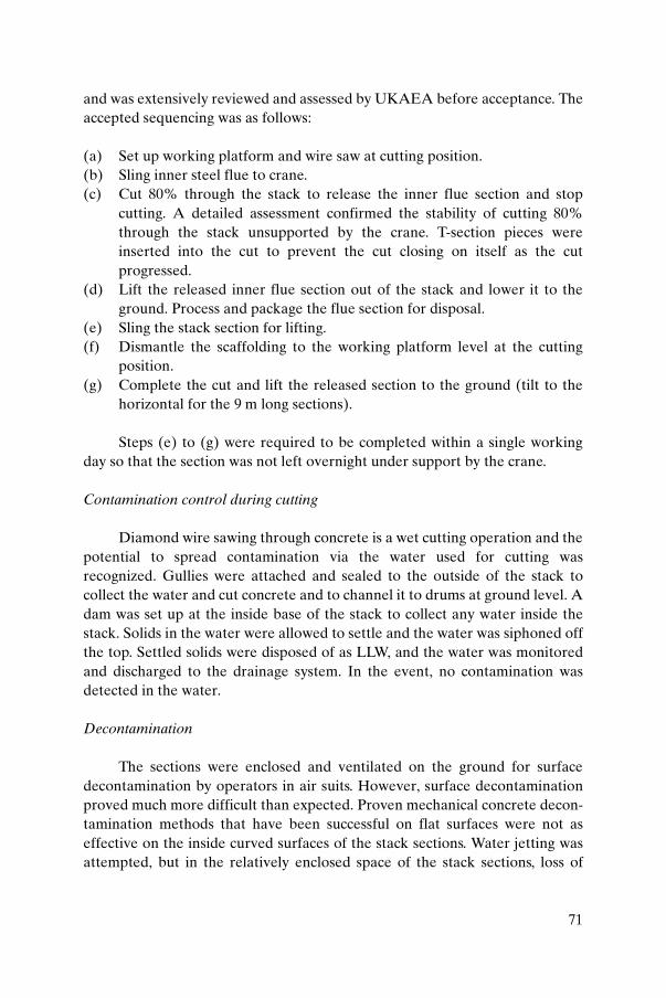
71
and was extensively reviewed and assessed by UKAEA before acceptance. Theaccepted sequencing was as follows:
(a) Set up working platform and wire saw at cutting position.(b) Sling inner steel flue to crane.(c) Cut 80% through the stack to release the inner flue section and stop
cutting. A detailed assessment confirmed the stability of cutting 80%through the stack unsupported by the crane. T-section pieces wereinserted into the cut to prevent the cut closing on itself as the cutprogressed.
(d) Lift the released inner flue section out of the stack and lower it to theground. Process and package the flue section for disposal.
(e) Sling the stack section for lifting.(f) Dismantle the scaffolding to the working platform level at the cutting
position.(g) Complete the cut and lift the released section to the ground (tilt to the
horizontal for the 9 m long sections).
Steps (e) to (g) were required to be completed within a single workingday so that the section was not left overnight under support by the crane.
Contamination control during cutting
Diamond wire sawing through concrete is a wet cutting operation and thepotential to spread contamination via the water used for cutting wasrecognized. Gullies were attached and sealed to the outside of the stack tocollect the water and cut concrete and to channel it to drums at ground level. Adam was set up at the inside base of the stack to collect any water inside thestack. Solids in the water were allowed to settle and the water was siphoned offthe top. Settled solids were disposed of as LLW, and the water was monitoredand discharged to the drainage system. In the event, no contamination wasdetected in the water.
Decontamination
The sections were enclosed and ventilated on the ground for surfacedecontamination by operators in air suits. However, surface decontaminationproved much more difficult than expected. Proven mechanical concrete decon-tamination methods that have been successful on flat surfaces were not aseffective on the inside curved surfaces of the stack sections. Water jetting wasattempted, but in the relatively enclosed space of the stack sections, loss of

72
visibility because of the water spray became a problem. The only successfulmethod was working by hand with needle guns and similar tools. This was aslow process and it was made more so by the low trigger rates necessary withsuch tooling to avoid hand and arm vibration problems. Thus it took consid-erably longer than planned to decontaminate the inside surfaces of the sections.
I.B–4.2. IMPLEMENTATION
The SGHWR stack was dismantled between 15 February and 19 March2002. Dismantling activities went very well, were carried out according to theplan and were successfully completed without incident. Dismantling work wasdelayed for a total of eight days during this period owing to adverse weather(high winds). Stack dismantling operations are shown in Fig. I.B–5 anddiamond wire sawing is shown in Fig. I.B–6.
Decontamination of the stack sections took considerably longer thanplanned. The intended decontamination method, scabbling with rotary flapwheel type tools, was not effective. Scabbling with needle gun type tools wasmore effective but progress was slow and it was made more so by the lowtrigger times. UKAEA allowed the contractor time to explore alternativedecontamination methods, but a more effective method was not identified.Decontamination work continued with needle gun type tools and was finallycompleted in mid-September 2002. The decontaminated stack sections areshown in Fig. I.B–7.
The contractor managed the working areas for the project underUKAEA control. The contractor maintained the working documentation,including method statements, risk assessments, plant records, training records,etc. UKAEA monitored the documentation and checked that it was correctand that work was carried out in accordance with the accepted documentation.UKAEA organized regular (unannounced) safety walkrounds of the workingareas by industrial safety specialists. No significant safety issues were raised.This was a project with significant safety risks and it was completed without anysafety problems or issues.
The contract was completed at 110% of the original contract price, andthe 10% increase was entirely due to UKAEA’s share of weather delay costs.The dismantling work was carried out to the accepted contract programme, butthe decontamination problems resulted in late overall contract completion.

73
FIG. I.B–5. SGHWR stack decommissioning: lifting operations.

74
FIG. I.B–6. SGHWR stack decommissioning: wire sawing.

75
FIG. I.B–7. Views of decontaminated SGHWR stack sections after decommissioning.

76
I.B–5. PROJECT REVIEW
A project review was held on completion of the stack decommissioning.The main points raised were the following:
(a) All parties considered the project a success. The key factors contributingto this were:
(i) Good project planning and definition with clear contract require-ments, responsibilities and interfaces.
(ii) Good work planning with concise and appropriate controllingdocumentation.
(iii) Good teamwork and cooperation between UKAEA and thecontractor.
(iv) Good safety management. There were significant safety risks withthis project and the work was properly managed such that no safetyproblems occurred.
(b) The decommissioning problems and delays were noted but did not signif-icantly detract from the overall success of the project.
The SGHWR stack was successfully decommissioned in 2002 to reducethe visual impact of the SGHWR facility.
BIBLIOGRAPHY TO ANNEX I.B
SGHWR Ventilation Stack Factsheet, UKAEA web site, April 2002,www.ukaea.org.uk/reports/generaldpf/Ventilation_Stack.pdf
77
Annex I.C
UNITED STATES EXPERIENCE OF STACK DISMANTLING: STACK DISMANTLING AT THE IDAHO NATIONAL ENGINEERING
AND ENVIRONMENTAL LABORATORY
I.C–1. INTRODUCTION
Since its establishment in the late 1940s, the Idaho National Engineeringand Environmental Laboratory (INEEL) has built and operated 52 nuclearreactors. Since most of these were built to support reactor safety research forvarious types of electrical power generating nuclear systems, most wereoperated for only relatively short periods of time before being shut down anddecommissioned. Many of these reactor facilities contained their own exhaustsystems including a dedicated exhaust stack. The size and complexity of thesestacks ranged from relatively short and simple to tall and complex. In general,heights ranged from slightly less than 30 m to greater than 60 m. Constructionranged from simple, small diameter metal piping supported on a concrete basewith anchoring cables, to massive brick lined concrete structures of more than10 m diameter. Contamination within these stacks consisted primarily of mixedfission products (137Cs, 60Co and 90Sr). Very low levels of 235U existed in some ofthe stacks. The following sections describe the decontamination and decommis-sioning (D&D) efforts associated with two types of stack located at the INEEL.
I.C–2. INITIAL ENGINE TEST FACILITY
The Initial Engine Test (IET) facility was built in the 1950s to supporttesting of the Aircraft Nuclear Propulsion reactors which were being developedand tested at the INEEL. The reactors themselves were located on double-wide railroad cars and were thus mobile between a large hot shop and the IETfacility where the tests were conducted. An aerial photograph showing the IETstack and test facility, the connecting railroad tracks and the supporting hotcells is given in Fig. I.C–1.
The IET facility was decommissioned as a series of small individual tasksor projects. That is, the duct, stack, underground control centre and supportbuildings were all treated as separate projects and decommissioned individ-ually. Of these portions of the overall facility, the stack contained the mostradioactive contamination and presented the greatest challenge.

78
The stack presented a challenge because it was large (53 m tall, 10 m indiameter at the base and 5 m in diameter at the top), contained loose contami-nation and represented a large waste volume (660 m3) to be disposed of at theRadioactive Waste Management Complex. The risk of industrial type accidentsis also very high when performing conventional dismantling of large stacks suchas this. For these reasons, non-conventional dismantling techniques wereconsidered for the IET stack.
Conventional dismantling techniques for stacks such as this usuallyinvolve large platforms which are placed at the top of the stack and which allowmanual removal of pieces of the stack as the platform is lowered. Pieces areremoved from the top of the work area on the stack either by usingjackhammers or by using concrete saws to cut through the stack wall. Removedpieces are usually dropped or lowered into the interior of the stack and thenpackaged at the stack base before being removed and disposed of. Conductingthese activities at great heights, accompanied by lowering or dropping largepieces of concrete, often puts the workers at risk. The chance of environmentalproblems through release of contaminated dust is also increased. Decommis-sioning a stack in this manner not only presents unnecessary risk to theworkers, but is also time consuming and costly.
Because of the problems associated with conventional stack removaltechniques, a new approach was investigated for D&D of the IET stack. In thiscase it was desired to improve worker safety, decrease the amount of waste
FIG. I.C–1. IET facility with exhaust stack.

79
generated and reduce the cost of decommissioning the stack. On-site disposalof the stack was desired since it would reduce the amount of waste going to theradioactive waste disposal site.
A decision was made to decontaminate the stack in place, and then usehigh explosives to fell it into a prepared trench at the IET site. The plan was todecontaminate the stack to a level such that the contamination left in therubbleized and buried stack would decay to agreed upon release levels(1 mSv/a to a maximally exposed individual) within an institutional controlperiod of 100 years. Following decontamination of the stack interior andconfirmation of the amount and types of contamination remaining, a trenchwould be dug out from the base of the stack, and high explosives would be usedto drop the stack into the trench. The felled stack would then be rubbleized asnecessary and buried in place. A permanent marker would be installed and thearea monitored as necessary to prevent intrusion until the radionuclidesdecayed to release levels. Thus plans were made for the partialdecontamination and explosive demolition of the IET stack.
Decontamination of the stack was accomplished by first shovelling loosedebris and a sludge-like material from the bottom of the stack. This materialconsisted mostly of dirt, which had settled to the concrete base of the stack overthe years. The material was lightly contaminated (about 0.12 mSv/h) with Co,Cs and Sr. The next step in the decontamination process was to vacuum thebase and interior walls of the stack to remove further loose material. Followingthis, a pressurized sandblasting unit was used to clean the interior of the stack.Following sandblasting, the interior of the stack was again vacuumed to removesand and loose contamination. Surface radiation surveys were then conductedto determine if spots or areas of contamination had been missed during thedecontamination operation. Samples of concrete from the interior of the stackwere then removed and analysed in a laboratory to determine residual isotopesand their concentrations. When it was determined that any isotopes remainingin the wall of the stack would decay to release levels within the defined timeperiod (see above), permission was given to proceed with explosive demolitionof the stack. It should be noted that almost all of the original contaminationexisted within the bottom 5 m of the stack. This made decontaminationrelatively easy since only the bottom 5 m needed to be cleaned.
An explosives demolition contractor (Blasting and VibrationConsultants) was then hired to perform the actual stack dismantling. Soil wasexcavated from around approximately half of the stack foundation and a largetrench was dug out radially from this part of the foundation. The stack, exposedfoundation and trench can be seen in Fig. I.C–2.
Holes were then drilled into the stack base and supporting concrete piles,as shown in Fig. 20 in the main text. The explosive charges were placed within

80
FIG. I.C–2. IET stack, exposed foundation and trench.

81
these holes and detonated in such a fashion as to cause the stack to fall directlyinto the trench that extended out from its base. The stack can be seen on its waydown in Figs I.C–3(a) and (b). Somewhat surprising was the complete collapseof the stack when it hit the bottom of the trench. This can be seen in Fig. I.C–4.It was expected that manual or explosive actions might be necessary tocompletely collapse the stack once it was in the trench. However, its massiveweight and the force with which it hit the trench bottom caused it to completelycollapse. The surrounding area was checked for radiation. In particular, a gridpattern for 10 m on each side of the trench was marked out and each gridelement was carefully surveyed with a handheld (pancake probe type)radiation detector. Also, soil samples were collected from randomly selectedgrid elements and were sent to a laboratory for analysis. Since no radiationabove the background was found either from the handheld survey or from thesamples analysed in the laboratory, the trench was filled with soil, thuscompleting burial of the rubbleized stack.
This proved to be a very safe and cost effective solution for decommissioningof the IET stack. The total cost of the entire operation was less than US $50 000,and the generation of over 660 m3 of waste was avoided. Although the industrialrisk to workers avoided by not performing a manual demolition of the stack is notquantifiable, it is certainly significant. Annual environmental monitoring of thearea where the stack is buried has shown no adverse impact on the site. This hasproven to be a very satisfactory way of decommissioning stacks of this type. Moredetails on the IET decommissioning project are given in Ref. [I.C–1].
I.C–3. AUXILIARY REACTOR AREA III FACILITY
Another very common type of stack that exists at the INEEL includesone which was decommissioned at the Auxiliary Reactor Area (ARA) facility.These stacks are simple, thin walled metal pipes or tubes mounted on aconcrete base and supported by cables attached at varying elevations andanchored to metal or concrete objects at some distance from the base. Since airemission standards do not permit the release of large amounts of radioactivity,these stacks are also only very lightly contaminated, usually with mixed fissionproducts as in the IET stack. Where space exists, these stacks are simply pulledover by heavy equipment and are then cut up and disposed of once they are onthe ground.
The 50 m stack at ARA-III can be seen being pulled over in Figs I.C–5and I.C–6. In this case the base bolts which attached the stack to its concretepad or base were removed and its supporting cables cut. A preattached cable

82
FIG. I.C–3. IET stack fall.
(a)
(b)

83
FIG. I.C–4. IET stack collapse after fall into trench.
FIG. I.C–5. ARA-715 stack at start of fall.

84
was connected to a large end loader/excavator and pulled down. Once the stackwas on the ground, its internals were surveyed for radioactive contamination.Since very little was found, the metal stack was torch cut and disposed of asmildly contaminated material.
Again, this method of disposing of stacks is very safe and cost effective, inmost cases entailing a total cost of only a few thousand dollars. If the stacks arecontaminated, waste disposal costs often exceed the demolition costs. Givenproper precautions to avoid pulling the stack onto other buildings orequipment, this option can be performed very safely. More details on the ARAdecommissioning project are given in Ref. [I.C–2].
REFERENCES TO ANNEX I.C
[I.C–1] STOLL, F.E., Final Report of the Decontamination and Decommissioning ofthe Initial Engine Test Facility and the IET Two-Inch Hot-Waste Line,Rep. EGG-2468, INEEL, Idaho Falls, ID (1987).
FIG. I.C–6. ARA-715 stack during fall.
85
[I.C–2] LABUY, S.A., Final Report — Decontamination and Decommissioning ofAuxiliary Reactor Area III, Rep. EGG-ER-114093, INEEL, Idaho Falls, ID(1994).

86
Annex I.D
UNITED STATES EXPERIENCE OF STACK DISMANTLING: DECOMMISSIONING OF A BRICK STACK
AT THE MOUND SITE
I.D–1. INTRODUCTION
The stack was located at the Mound site in Miamisburg, Ohio. The sitehas been involved with radioactive materials since 1948. It is currently beingdecommissioned and remediated by CH2M Hill for the US Department ofEnergy.
The stack was built in the mid-1960s (Fig. I.D–1) and supported theexhaust system of a 238Pu processing building. The building had three separateexhaust systems (single HEPA banks) which were directed to an air plenumand stack fan located on a raised platform adjacent to the brick stack. During afilter change, the duct, the plenum, the fan and the stack became contaminatedwith 238Pu (weak gamma radiation of little radiation concern but also highenergy alpha radiation of considerable radiation concern). A new plutoniumprocessing facility was built in the early 1970s. Its ventilation system wasconnected to the original plenum, fan and stack. The original processing
200 ft (61 m) Stack
Public Road
Public Golf Course
FIG. I.D–1. Mound facility stack and its surroundings.

87
building was decontaminated and decommissioned (D&D) in the late 1980sand early 1990s. It was during this time that plans started to be formulatedconcerning the disposition of the brick stack.
I.D–2. DESCRIPTION
The stack was 200 ft (61 m) tall with an outer diameter of approximately16 ft (4.9 m) at the base tapering to approximately 7 ft (2.1 m) at the top. Thewall thickness was 18 in (0.5 m) at the base and 8 in (0.2 m) at the top. The stackwas constructed of bricks and mortar, and its inside surface was coated withgilsonite (a natural form of asphalt).
There were four openings in the stack: a 2 ft (0.61 m) × 3 ft (0.91 m)‘manway’ at the base, an 8 ft (2.4 m) × 4 ft (1.22 m) air inlet duct opening at the16 ft (4.88 m) to 24 ft (7.3 m) elevation, and two air monitoring probe holes atthe 104 ft (31.7 m) elevation.
Two structural steel platforms were located on the stack, one at the 100 ft(30.5 m) elevation and the other at approximately 192 ft (58.5 m). Both wereaccessible from the ground by means of a ladder with safety cage and safety tie-on. In addition, aircraft lights were located on the platforms, and a lightningarrester system with four lightning rods and a ground wire were attached to thestack.
A reinforced concrete base pad 8 ft (2.4 m) deep in three steps — 4 ft(1.22 m), 2 ft (0.61 m) and 2 ft (0.61 m) — supported the stack.
The remaining portions of the stack system included the 4 ft (1.22 m)diameter exhaust duct and associated support structure from the building tothe plenum, the exhaust plenum with support platform and the stack exhaustfan. The ductwork was generally welded 1/8 in (3.1 mm) thick carbon steel, andthe plenum was fabricated from 18 gauge carbon steel.
I.D–3. PLANNING
The stack had to be characterized to determine the extent of the contam-ination problem and at the same time still support an active nuclear facility. Thecharacterization included: (a) radiological background, (b) loose alphacontamination, (c) fixed alpha contamination, (d) depth of penetration ofcontaminants into the walls and floor, (e) a video recording of the stack interiorfor visual inspection, and (f) nature and extent of the radiological and otherhazardous contamination within the stack.

88
I.D–4. CHARACTERIZATION
The stack was characterized in 1990 after 25 years of operation. The stackwas visually inspected, and data were collected from direct measurements,smear samples, debris and core samples. Subsections of core samples and debriswere analysed for TCLP (toxicity characteristic leachate protocol) analytes andradioisotopes of Th, U, Pu and Am. Core samples were taken at 1.0 ft (0.3 m),20.0 ft (6.1 m) and 60.0 ft (18.3 m) above the stack base (see Fig. 6 in the maintext). A core was taken from the concrete base. The core samples were cut intoprescribed sections. The results for the innermost ¼ in (6.2 mm) and next ¼ in(6.2 mm) depth are presented as first cut and second cut below. Smear sampleswere taken from areas inside the stack at 2.0 ft (0.61 m), 6.0 ft (1.8 m), 20.0 ft(6.1 m) and 200 ft (61 m).
A US Environmental Protection Agency approved lab performed theTCLP sample analyses. The TCLP protocol requires testing for metals(inorganics), herbicides, pesticides, and volatile and semivolatile organics. TheTCLP protocol does not include asbestos.
None of the TCLP results were above maximum permissible contaminantlevels, hence the stack would not require waste categorization as chemicallyhazardous or mixed waste. To determine the levels and constituents within thestack, an isotopic analysis using alpha spectrometry and liquid scintillationspectrometry was completed for the innermost cut of the 20 ft (6.1 m) wall coresample directly across from the inlet (impingement point).
The single sample isotopic results are presented in Table I.D–1. Tominimize cost, this sample was used to normalize data from other samples andcalculate estimated activities based on the comparison of 238Pu results.
Isotopic activity ratios indicate that the combined radioactivity from thetested isotopes of Th, U, Pu and Am totals approximately 2.2 times the 238Puactivity.
An assumption was made that isotopic ratios would be constantthroughout the sampling matrix. The ratio was used to calculate total activityvalues for waste quantification purposes. Table I.D–2 lists the measured 238Puresults along with the estimated total activities.
The first and second cut figures refer to ¼ in (6.35 mm) slices from thecore sample. The first cut is the inner surface; the second cut is the next ¼ in(6.35 mm) slice.
Sample sites were chosen where hazardous materials would be detectedand that would provide a worst case indication of radiological contamination. Itwas originally assumed that the impingement point from the incoming ductwould result in the highest contamination site. However, this assumptionproved to be incorrect. The point of impingement was probably kept dry by the

89
TA
BL
E I
.D–1
. ISO
TO
PIC
AN
ALY
SIS
OF
ST
AC
K C
OR
E S
AM
PL
E
Isot
ope
Act
ivit
y co
ncen
trat
ion
Err
or
Act
ivit
y(%
)
Spec
ific
act
ivit
y M
ass
(g)
Mas
s(%
)(p
Ci/g
)(B
q/g)
(pC
i/g)
(Bq/
g)(C
i/g)
(Bq/
g)
Th-
228
6.8
0.25
22.
80.
104
1.03
8.20
E+
23.
04E
+13
8.29
E–1
51.
26E
–8
Th-
230
4.7
0.17
45.
40.
200
7.11
2.06
E–2
9.65
E+
82.
28E
–93.
47E
–3
Th-
232
2.5
0.09
31.
20.
044
0.38
1.10
E–7
4.08
E+
32.
27E
–534
.5
U-2
3416
.00.
593
4.0
0.14
82.
426.
23E
–32.
31E
+8
2.57
E–9
3.90
E–3
U-2
351.
20.
044
0.9
0.03
30.
181.
92E
–67.
12E
+4
6.25
E–7
0.95
U-2
3814
.00.
519
3.0
0.11
12.
123.
30E
–71.
22E
+4
4.24
E–5
64.5
Pu-
238
300.
011
.11
34.0
1.25
945
.41
1.71
E+
16.
34E
+11
1.75
E–1
12.
67E
–5
Pu-
239/
240
0.51
0.01
90.
50.
019
0.08
6.20
E–2
/2.
27E
–12.
30E
+9/
8.42
E+
93.
53E
–12
5.36
E–6
Pu-
241
270.
010
.013
5.0
5.00
40.8
71.
03E
+2
3.82
E+
122.
62E
–12
3.98
E–6
Pu-
242
<1.
4<
0.05
2N
eglig
ible
0.21
3.93
E–3
1.46
E+
83.
56E
–10
5.42
E–4
Am
-241
1.
30.
048
1.7
0.06
30.
203.
43E
+0
1.27
E+
113.
79E
–13
5.76
E–7
Tota
l61
8.4
22.9
2N
AN
A10
0N
AN
A4.
39E
–510
0
Not
e: N
A: n
ot a
pplic
able
.

90
Tabl
e I.
D–2
. ST
AC
K R
ESU
LTS
FO
R P
LU
TO
NIU
M
Sam
ple
type
Sam
ple
loca
tion
Pu-
238
acti
vity
To
tal c
alcu
late
dac
tivi
tyFi
rst c
utSe
cond
cut
(pC
i/g)
(Bq/
g)(p
Ci/g
)(B
q/g)
(pC
i/g)
(Bq/
g)
Cor
eF
loor
3 30
012
2.22
823.
047
300
270.
37 (
1st)
Cor
e1
ft (
0.3
m)
inne
r w
all
1 70
062
.96
672.
483
700
137.
04 (
1st)
Cor
e20
ft (
6.0
m)
inne
r w
all
300
11.1
14.
70.
1766
024
.44
(1st
)
Cor
e60
ft (
18.0
m)
inne
r w
all
4 20
015
5.56
622.
309
300
344.
44 (
1st)
Deb
ris
Flo
or u
nder
inle
t28
0 00
010
370
Neg
ligib
le61
7 00
022
852
Deb
ris
Flo
or c
entr
e14
0 00
05
185.
2N
eglig
ible
308
000
11 4
07
Deb
ris
Flo
or o
ppos
ite
inle
t62
0 00
022
963
Neg
ligib
le1
370
000
50 7
41
Smea
r2
ft 6
in (
0.75
m)
inte
rior
12
0 00
04
444.
4N
eglig
ible
264
000
9 77
7.8
Smea
r20
ft (
6.0
m)
inte
rior
7 20
026
6.67
Neg
ligib
le16
000
592.
59
Smea
r20
0 ft
(60
m)
inte
rior
120.
44N
eglig
ible
260.
96

91
blast of dry conditioned air from the building, which would account for theresults being significantly lower than expected.
In addition to the lab data above, field data for surface alpha emissionsare listed in Table I.D–3.
A video survey (Fig. I.D–2) of the interior of the stack indicated that thegilsonite coating had failed at the mortar joints but appeared intact on the bricksurfaces. The debris at the base of the stack was primarily the coating material,dirt and mortar.
Of greater concern was the quantity and activity level of contaminatedmaterial at the base of the stack — over 500 lb (227 kg) of debris and onesample with an activity of over 100 nCi/g (3700 Bq/g).
I.D–5. DECONTAMINATION AND DEBRIS REMOVAL
Originally this project was to be carried out with an inflatable plug beinginserted into the stack to seal it while the material was removed. Airlocks withHEPA exhausts were fabricated and installed at the stack manway. Beforestarting the fieldwork, the Environmental Monitoring Group did not want thestack to be plugged, considering that having the natural draft from the stackduring debris cleanup would be preferable to plugging (better to have anyemissions at 200 ft (61 m) above the ground rather than any possibility ofemissions at ground level).
TABLE I.D–3. STACK FIELD DATA
LocationSmear Direct
(dis · min–1 · (100 cm2) –1) (Bq/cm2) (dis · min–1 · (100 cm2) –1) (Bq/cm2)
N 2 ft 500 0.083 16 000 2.67
E 2 ft 1 200 0.20 50 000 8.33
S 2 ft 600 0.10 35 000 5.83
W 2 ft 3 000 0.50 130 000 21.67
N 6 ft 1 000 0.17 24 000 4.0
E 6 ft 1 500 0.25 45 000 7.50
S 6 ft 1 500 0.25 35 000 5.83
W 6 ft 2 000 0.33 110 000 18.33
Inlet 20 ft 1 000 0.17 18 000 3.0
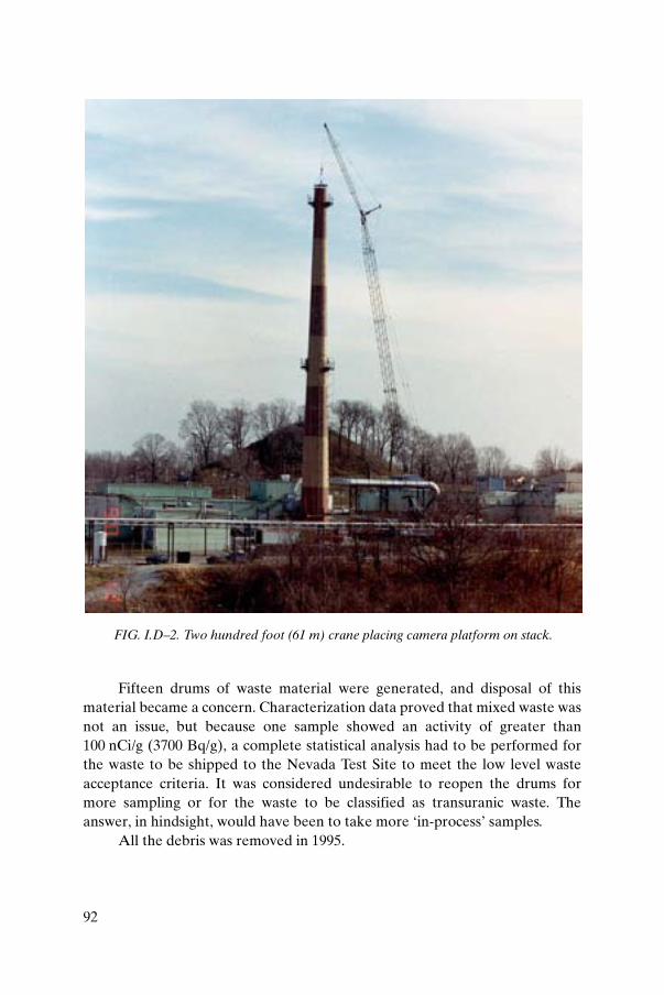
92
Fifteen drums of waste material were generated, and disposal of thismaterial became a concern. Characterization data proved that mixed waste wasnot an issue, but because one sample showed an activity of greater than100 nCi/g (3700 Bq/g), a complete statistical analysis had to be performed forthe waste to be shipped to the Nevada Test Site to meet the low level wasteacceptance criteria. It was considered undesirable to reopen the drums formore sampling or for the waste to be classified as transuranic waste. Theanswer, in hindsight, would have been to take more ‘in-process’ samples.
All the debris was removed in 1995.
FIG. I.D–2. Two hundred foot (61 m) crane placing camera platform on stack.

93
I.D–6. DEMOLITION
Several studies and alternatives concerning stack demolition werereviewed. A value engineering study showed implosion as the most costeffective means of stack demolition; however, the cost of using explosives wasonly US $15 000 less than that of normal crane and clamshell demolitionmethods.
These stack demolition plans required approval by regulatory agencypersonnel from the US and Ohio environmental protection agencies. It wasconsidered that the effort and cost involved in producing the level of documen-tation required to support the implosion method and ensure public safetywould exceed the $15 000 cost difference. This situation was exacerbated by thefact that the stack was within 100 yd (91 m) of a public golf course and a publicroad.
The decision was made to contract the demolition of the stack and theadjacent production building (operations in the building had ceased), and theuse of explosives was prohibited.
The prime contractor selected was URS, Oak Ridge, Tennessee, andsubcontractors included the Cleveland Wrecking Company and InternationalChimney Corporation. The contractor was responsible for developing thespecific demolition plan and a ‘fenceline’ dose calculation, and for respondingto Environmental Protection Agency comments until approval was achieved.The essential elements of the approved plan were:
(a) The masonry stack was removed after engineered controls were applied.The stack was removed by trained workers who specialize in demolishingstacks and are considered experts in this field. The stack was maintainedunder negative pressure while demolition was in progress. Demolitiondebris was dropped inside the stack and collected at the interior base.Waste was removed using a skid steer loader.
(b) An airlock measuring 75 ft (22.9 m) long, 14 ft (4.3 m) wide and 10 ft(3.0 m) high was installed and sealed around the access hatch of the stack(Fig. I.D–3). It was manufactured by installing a scaffold frame andattaching two heavy duty plastic layers. The airlock consisted of threerooms separated by double-layered plastic doors. Four HEPA ventilationunits at 2100 ft3/min (1 m3/s) per unit were attached to provide negativepressure — two units servicing the chamber nearest to the stack and oneunit each in the intermediate and outer chambers. The chamber nearestto the stack (room 1) contained the skid steer loader. The loader periodi-cally removed debris from the base of the stack and placed debris intowaste boxes in room 1. The boxes were staged in room 2. Debris was only

94
removed from the stack base when overhead work/demolition was halted.When the waste boxes were full, they were sampled and closed, grosscontamination was removed and then the boxes were moved into room 3.Radiological surveys were performed on the closed boxes in room 3before removal from the airlock.
(c) A fixative fog was placed on the interior of the 48 in (1.22 m) duct fromthe building to the plenum, the plenum and the stack fan. The ductworkwas cut or unbolted, removed in sections and placed in waste containers.The plenum, stack fan blower and motor were removed and placed inwaste containers (Fig. I.D–4).
(d) A bracket and cable scaffold was installed on the stack to allow stackworkers to break up the brick from the top, pushing the brick into thestack interior (Figs I.D–5 and I.D–6).
(e) The access hatch at the bottom of the stack was enlarged to approxi-mately 8 ft (2.4 m) high × 4.5 ft (1.37 m) wide to allow access for debrisremoval. An engineering study was performed to evaluate enlarging thehatch. A new lintel was bolted into place and saw cuts were made to
FIG. I.D–3. Fabrication of airlock.

95
accommodate new side jambs. The hatch and remaining brick wereremoved to create the larger opening.
(f) The octagon shaped stack platforms at 100 ft (30.5 m) and 192 ft (58.5 m)were disassembled and removed in sections.
(g) The stack monitoring sample lines, the lightning arrester system and theassociated ground wire were removed.
(h) The original aircraft lights were removed. Temporary warning lights wereinstalled in accordance with US Federal Aviation Administration (FAA)regulations, and the FAA was notified on a daily basis until the stackheight was reduced to less than 150 ft (45.7 m).
(i) Two 2100 ft3/min (1 m3/s) HEPA ventilation units were attached to aprefabricated cover where the existing ducting penetration originallyentered the stack.
(j) The four 2100 ft3/min (1 m3/s) HEPA ventilation units attached to theairlock and the two 2100 ft3/min (1 m3/s) HEPA ventilation units attachedto the stack were started up. Negative pressure with respect toatmosphere was verified on a daily basis.
FIG. I.D–4. Lowering ‘fogged’ exhaust duct.

96
The stack workers were trained to collect routine radiological samplesand to verify ventilation flows using smoke tubes. All stack workers worepersonal air samplers to record exposure.
FIG. I.D–5. Bracket and cable scaffold.

97
Various encapsulants and water misting were used throughout theproject, particularly when the stack height was reduced to the 25 ft (7.6 m) levelwhere the two HEPA exhausters became ineffective. Below this level, standardexcavators with hydraulic grapple attachments were used for the remainingdemolition.
Stack debris totalling 7500 ft3 (215 m3) was packaged into intermodalcontainers, which were loaded on railcars for low level radioactive wastedisposal at the burial site at Envirocare in Utah. No on-site burial is allowed atthe Mound site. The stack removal project was successfully completed in thesummer of 2003.
I.D–7. SITE RESTORATION/TRANSITION
Plans are currently being made for the partial removal of the remainingstack foundation.
FIG. I.D–6. Stack platforms gone, less than 100 ft (30.5 m) of stack remaining.

98
Annex I.E
WINDSCALE PILE STACK DECOMMISSIONING, UNITED KINGDOM
I.E–1. INTRODUCTION
The Windscale Pile stacks served to discharge cooling air from thereactors constructed to produce nuclear material for the United Kingdom’sfirst atomic weapons. The stacks have formed a distinctive part of theCumbrian skyline for some 55 years. Initially seen as visible progress towards anuclear future, they were later to become associated with the worst nuclearaccident in the United Kingdom and internationally known as landmarks ofthe Sellafield site.
The Windscale Pile stacks, shown in Fig. I.E–1, form a distinctivelandmark of the Sellafield site. They are curiously shaped, massive reinforcedconcrete structures standing 130 m above ground level and visible for manymiles around west Cumbria.
The outward simplicity of each stack belies a complex engineeringstructure which allowed their connection to a nuclear pile designed to produceplutonium for atomic weapons during the early 1950s. The reactors were cooledby forcing air over the pile and passing the heated air directly to atmospherevia the stacks. The weapons programme was considered a matter of nationalpriority, and speed was of the utmost importance. Many aspects of the workassociated with the project progressed in parallel, and a shortage of materialsand human resources added to the challenges faced during construction.Despite these challenges the stacks were constructed on time, and the wholeproject (including the other process plants) associated with the weaponsprogramme was delivered on schedule.
I.E–2. CONSTRUCTION
The stacks were intended to be conventional circular structures, butproblems were envisaged with potential release of radioactive contaminationfrom the core to atmosphere. As a consequence, the stacks were redesigned toincorporate filtration systems. However, as construction of the first stack hadprogressed to a height of 30 m, the filters were placed at the top of the stackinstead of at the bottom where they conventionally would have been located.The redesign resulted in the distinctive square section at the top of each stack(Fig. I.E–2).

99
Although the stacks appear simple from the outside, they hide a complexcivil structure utilizing novel materials and construction techniques. Thestructure is a composite of reinforced concrete and structural steelwork. A
FIG. I.E–1. Windscale Pile stacks.

100
total of 20 000 t of concrete and bricks and 1000 t of structural steelwork wereused in the construction. The interior contained aluminium, steel and asbestoscement boxes filled with fibreglass to insulate the stack structure from the hot
FIG. I.E–2. Detail of top of Windscale Pile stack.

101
exhaust gases (1 t of air per second at 180°C). The filter gallery housed multiplefilters which had to be taken to the top of the stack and the contaminated filtersreturned to the base in massive steel flasks; these were handled on trolleyswhich ran on rails at the top of the stack.
The haste in the construction of the stacks challenged conventionaldesign. Forced changes during construction, such as the filter galleries at thetop of the stack, had to be accommodated through application of soundengineering, cleverly applied in difficult circumstances.
I.E–3. OPERATION
The Pile reactors performed well in operation and very little contami-nation was released from the core. This meant that the filters did not have toremove large quantities of contamination. The filters were constructed frommineral wool covered in oil, but in the hot air stream from the reactor the oilevaporated rapidly. This meant that a lot of effort was put into the filterchanging process and developing new designs to mitigate the problem. Thisproblem, coupled with the fact that the reactors worked so well, led to anargument that the filters were not necessary. Fortunately the filters wereretained, and the accident of 1957 validated this decision.
In October 1957 a fire in the core of Pile 1 led to significant quantities ofcontamination being released. Some of this contamination travelled in thecooling air stream, up the stacks to the filters. The filters removed approxi-mately 65% of the radioactivity that passed up the stack, and played asignificant role in reducing the impact of the accident to the public. This meantthat the filters and the interior of the stack became contaminated, making thelater job of cleanup more challenging.
I.E–4. DECOMMISSIONING
The Piles were permanently shut down following the fire, and the stackswere placed into a state of care and maintenance. Over time, the structures atthe top of the stacks began to deteriorate, and structural assessments carriedout as part of the care and maintenance work showed that it would be sensibleto remove the filter galleries (the square section) before deteriorationprogressed to a point that they were rendered unsafe.
Once the decision was taken to dismantle the filter galleries, an approachhad to be developed to address the unique aspects which prevented

102
conventional techniques being employed. Dismantling of such large contaminatedcivil structures was not typical of the nuclear industry. The challenges included:
(a) Height. The top of the stacks was 130 m above ground level. Access to thetop was via an installed ladder system. A new access system was neededto allow civil dismantling work and waste handling on a routine basis.
(b) Contamination and radiation. The fire led to significant quantities ofradioactivity being released and deposited in the Pile 1 stack and on thefilters. This contamination gave rise to high radiation levels in thestructure that restricted access. Radiological conditions in Pile 2 were lessrestrictive. The contaminants were largely fission products, with predomi-nantly 137Cs remaining.
(c) Poor records. The haste with which the stacks were built meant thatdrawing records for the structures were sometimes inconsistent. Data hadto be gathered to substantiate designs to ensure that a proposed solutionwas safe before it was implemented.
(d) No examples to follow. The Pile stack design and restrictions because ofthe fire were unique. No other structure in the world provided anexample to follow. The solutions adopted would have to match theproblem at hand and the team would have to learn from their ownexperiences.
(e) Sensitive structures around the base. A number of buildings that containedpersonnel, process equipment and nuclear fuel storage facilities were atthe base of each stack. These structures had to be protected from hazardsposed by dismantling operations. In addition, it had to be demonstratedthat occupancy of the buildings at the base of the stacks could continueduring dismantling work.
I.E–4.1. Decommissioning strategy
The approach adopted by the project team to deal with the challengeswas to assess each element of the work as a unique package and to devisesolutions for each specific problem.
The general strategy was to demonstrate solutions on the Pile 2 stack,which had lower levels of contamination and radiation. The experience gainedfrom operating the equipment on Pile 2 was applied to the Pile 1 stack, whereradiation and contamination levels were much higher.

103
I.E–4.2. Implementation of the strategy
The application of solutions to the stacks identified a number ofimportant issues:
(a) The stacks were inconsistent with drawing records, which led to arequirement for flexible solutions.
(b) Radiological conditions could only be fully assessed as work progressed,owing to the difficulty in gaining access prior to implementing solutions.
(c) Some of the best solutions came from outside the management team. Thisfact was recognized early on with civil contractors extensively employedon the project. Working relationships were developed to integrate bestpractice in the nuclear industry with practices in relevant areas fromoutside the industry.
Experience led to the recognition that standard off-the-shelf equipmentwas preferable to bespoke, custom solutions. The value of this approach wasenhanced by incorporating non-nuclear experience into the solutiondevelopment process, although conventional approaches had to be challengedto deliver cost effective solutions. Figure I.E–3 shows an example of how an
FIG. I.E–3. Asphalt shaver.
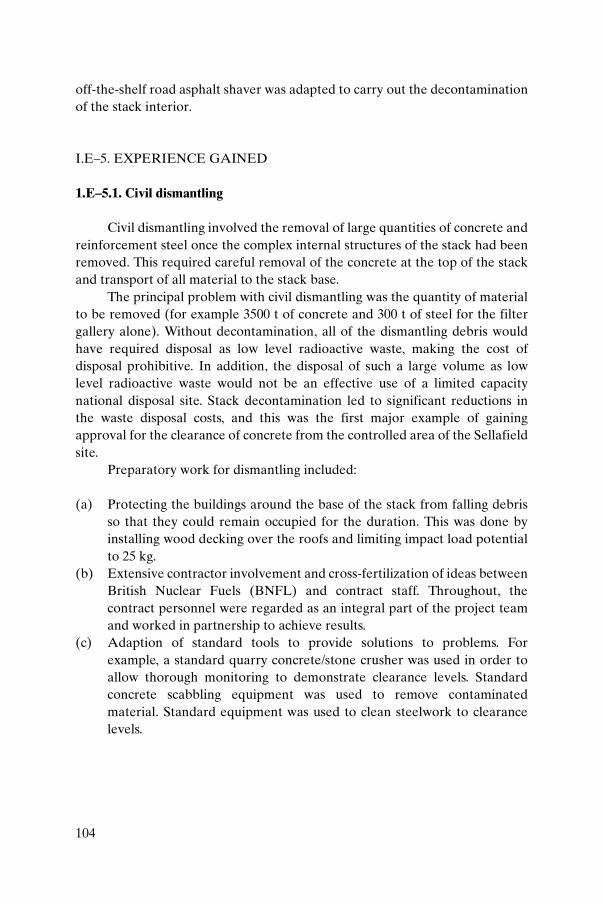
104
off-the-shelf road asphalt shaver was adapted to carry out the decontaminationof the stack interior.
I.E–5. EXPERIENCE GAINED
1.E–5.1. Civil dismantling
Civil dismantling involved the removal of large quantities of concrete andreinforcement steel once the complex internal structures of the stack had beenremoved. This required careful removal of the concrete at the top of the stackand transport of all material to the stack base.
The principal problem with civil dismantling was the quantity of materialto be removed (for example 3500 t of concrete and 300 t of steel for the filtergallery alone). Without decontamination, all of the dismantling debris wouldhave required disposal as low level radioactive waste, making the cost ofdisposal prohibitive. In addition, the disposal of such a large volume as lowlevel radioactive waste would not be an effective use of a limited capacitynational disposal site. Stack decontamination led to significant reductions inthe waste disposal costs, and this was the first major example of gainingapproval for the clearance of concrete from the controlled area of the Sellafieldsite.
Preparatory work for dismantling included:
(a) Protecting the buildings around the base of the stack from falling debrisso that they could remain occupied for the duration. This was done byinstalling wood decking over the roofs and limiting impact load potentialto 25 kg.
(b) Extensive contractor involvement and cross-fertilization of ideas betweenBritish Nuclear Fuels (BNFL) and contract staff. Throughout, thecontract personnel were regarded as an integral part of the project teamand worked in partnership to achieve results.
(c) Adaption of standard tools to provide solutions to problems. Forexample, a standard quarry concrete/stone crusher was used in order toallow thorough monitoring to demonstrate clearance levels. Standardconcrete scabbling equipment was used to remove contaminatedmaterial. Standard equipment was used to clean steelwork to clearancelevels.

105
1.E–5.2. BROKK application
The BROKK is a small scale multipurpose excavator type vehicle used todeploy a wide variety of equipment. It is a standard item of equipment widelyused and proven in the harsh environment of the construction industry(Fig. I.E–4).
The BROKK can be used to deploy a number of standard and modifiedstandard tools to the workface. These include percussive breaking tools, recip-rocating and circular saws, and clamping, lifting and shearing tools. Theequipment provides a high pressure hydraulic supply to ensure that the necessarypower can be obtained for a wide variety of tasks. It was used by the stack projectfor a number of applications, such as lining box removal, remote concretebreaking operations, cutting of rolled steel sections and other operations wherepersonnel access was restricted owing to dose or for safety reasons.
The usefulness of the equipment can be measured by the number ofdecommissioning projects that now employ BROKKs. This proliferation oftheir use could be considered as a direct consequence of the success achievedby their use on the Pile stack decommissioning project.
FIG. I.E–4. BROKK excavator.

106
I.E–5.3. Filter dismantling
Owing to the high levels of contamination and radiation in the Pile 1stack, working times were restricted and innovative solutions for filterdismantling were necessary. The solution demonstrated on Pile 2 for removal ofthe filter gallery section could not be directly applied to Pile 1.
The approach to the problem was to review alternatives that addressedthe specific concerns raised by implementing the solution adopted on Pile 2.The solution developed utilized a simple shearing tool deployed from chainblocks, and involved letting the cut sections of the filter gallery fall to the floorof the stack to be recovered later. The solution was simple and highly effective,significantly reducing cost and dose uptake.
The principal area of concern relating to adopting the proposed solutionwas the issue of aerial release of contamination when sectioned items of gallerydropped to the base of the stack. This issue required the project to challengeconventional thinking to demonstrate that the approach could be implementedsafely. Theoretical calculations backed up by close initial scrutiny of operationsdemonstrated that the approach was safe.
I.E–6. CONCLUSION
Removal of the Pile stacks has proven a tremendous learning experiencefor both BNFL and contractors who have worked in partnership with theproject over many years. It has visibly demonstrated the effect of combiningexpertise across industries to cost effectively realize practical solutions tocomplex problems.
The key aspects of the decommissioning project were to provide flexiblesolutions built upon standard, proven technology to ensure that they copedwell with the unexpected, and furthermore to challenge conventional thinkingto ensure that simple solutions were not allowed to become complex andunworkable.

107
Annex I.F
Z-PLANT URANIUM ENRICHMENT FACILITY OF SOUTH AFRICA: STRATEGY FOR THE DECOMMISSIONING OF THE
VENTILATION STACKS
I.F–1. INTRODUCTION
The purpose of this annex is to present the information and factorsrelevant to decommissioning as well as the derivation of a conceptual strategyfor decommissioning the stacks of the Z-plant in South Africa. In addition,regulatory requirements and criteria, as well as the information obtained frompreliminary characterization, are presented. The information interfaces andoptions are evaluated in terms of key factors (e.g. cost, waste class andquantities) in order to derive a proposed conceptual decommissioning strategy.
Construction of the semicommercial Z-plant started in 1978. The plantwas commissioned in the early 1980s. By 1994 it had become clear that the Z-plant would not be able to compete cost effectively with internationalproducers of enriched uranium for South Africa’s needs. The decision wasconsequently taken to shut down on 31 March 1995 and to immediatelycommence with decommissioning of the plant. Decommissioning up to theremoval of process equipment was completed in 1999.
In its lifetime the plant produced 225 t of enriched uranium at concen-tration levels of between 3.25% and 3.90%. The total quantity of uraniumreleased via the four stacks of the plant was approximately 1900 kg U-natequivalent. The plant has a design ventilation rate of 1000 m3/s.
Except for the removal of the emergency oil feed systems that wereinstalled on the stacks and the removal of the off-gas line, no decommissioningactivities were performed on the stacks.
Since 2000 the plant has been used as a temporary waste store, for whichthe natural ventilation through the stacks is sufficient. In view of the currentapplication of the plant, decommissioning of the stacks is not foreseen for theimmediate future. The development of a stack decommissioning strategy isnonetheless required for the ongoing liability assessment of the site.

108
I.F–2. STACK CHARACTERIZATION
Stack description
A single stack is considered for the characterization (Fig. I.F–1). Thestack includes the concrete structure and the steel plenum connecting the fanhouse with the stack. The fan house is an integral part of the building.
Physical characterization
The stack is 80 m in height and is erected on a foundation 12 m indiameter and 2.5 m thick. The stack outer diameter is nominally 5.6 m, with aninner diameter of 5 m.
The stack is constructed of reinforced concrete. The outer surface of thestack has a smooth finish while the inner surface is rough. The plenum isconstructed of epoxy coated carbon steel (Fig. I.F–2).
The stack has the following design features that are of importance tocharacterization and decommissioning:
(a) The stack is sealed from its base at the plenum connection point.(b) A water drain point is located at the plenum connection point with
draining facilities to the base of the stack (Fig. I.F–3).(c) A sump for water collection is also installed in the fan house.(d) The plenum and internal surface of the stack are accessible through a
bolted panel in the fan house. No other access points to the internalsurface exist, although the top of the stack can be reached by ladder andvia a number of platforms at various heights (Fig. I.F–4).
(e) The stack is equipped with an off-gas discharge point approximately 17 mfrom the base into the plenum of the stack. The discharge point is notaccessible and the off-gas line has been removed as part of the phase 2decommissioning project (Fig. I.F–5).
(f) A stack sampling point is installed at approximately 65 m from the base ofthe stack. The sampler is still functional.
A visual inspection of the stack showed that the stack components arestill in a good condition, without evidence of corrosion or deterioration ofcomponents or any indication of poor structural integrity. This probably resultsfrom the short operational period of the plant.

109
FIG. I.F–1. Stack considered for characterization.

110
FIG. I.F–2. Epoxy coated plenum.
FIG. I.F–3. Water drain point.

111
FIG. I.F–4. Platforms.

112
The stack material quantities are as follows:
— Concrete: foundation: 280 m3; stack: 350 m3. (These quantities are in situvolumes per stack and may increase by up to 60% for concrete in rubbleform.)
— Reinforcing steel: approximately 50 t.— Sheet steel: approximately 200 m2 and 11 t.
Radiological characterization
A radiological survey was performed to obtain information regarding theprevailing radiological condition of the inner surface of the stack. Owing toaccessibility limitations, most of the measurements, as well as the decontami-nation tests, were performed where the plenum enters the stack. Since the off-gas line also enters at this point, it is assumed that the highest contaminationlevels occur in this region. Nonetheless the stack was also surveyed at its topand approximately 15 m below the top.
FIG. I.F–5. Off-gas discharge point.

113
Source material
The plant was designed for operation with fresh uranium in the form ofUF6. Recycled uranium was not used as feed material. The contaminants aretherefore uranium that is slightly enriched in the 235U isotope in secularequilibrium with its short lived daughter products.
Emissions occurred mainly as UO2F2 aerosols due to UF6 releases. Theemission of uranium was also associated with the discharge of HF vapour.
Stack contamination
The level of contamination of the stack was evaluated in terms of surfacecontamination and activity concentration in the top 8 mm of the inner surfaceof the stack. Surface contamination is evaluated in terms of removable andtotal contamination levels. Owing to the rough inner surface of the concretesections of the stack, swipe sampling results provided only a qualitativeindication of the removability of the contamination.
Surface contamination levels were obtained on the various sections andare indicated in Table I.F–1. (The results are background (BG) corrected butare not statistically evaluated, in view of the purpose of the study.)
The following can be derived from the contamination evaluation:
(1) Internal steel sections are contaminated (mainly removablecontamination) to levels that require decontamination for clearanceconsideration.
(2) The two steel platforms at the top of the stack are contaminated (mainlyfixed contamination) to levels that require decontamination.
(3) The inner concrete surface of the stack is contaminated, with propagationof contamination into the top layer of concrete as indicated by the highbeta to alpha ratio.
(4) The highest contamination levels occur at the plenum inlet point, with agradual decrease at higher stack elevations.
(5) The stack base floor has localized contamination due to water that spilledfrom the water collection point (Fig. I.F–6).
(6) The gravel surrounding the water drain point outside the stack base iscontaminated.
Activity concentration levels in concrete were obtained in the zone wherethe highest surface contamination levels were indicated.
The radioactivity concentration levels were analytically determined fortwo inner layer thicknesses, i.e. 2–3 mm and 6–8 mm, as well as for the

114
TABLE I.F–1. RADIOLOGICAL CHARACTERIZATION OF THE Z-PLANT STACK (LOOSE AND TOTAL CONTAMINATION)
Section
Average smear sample results
(Bq/cm2)
Average total contamination results
(Bq/cm2)
Alpha Beta Alpha Beta
Plenum (steel)
Floor 0.74a 0.66 0.44 0.85
Sides 0.80a 0.71a 0.25 0.64
Stack concrete
Water collection point 1.20b 1.30b 1.03 195.00c
Plenum entry point 1 0.19b 0.12b 1.48 80.80c
Plenum entry point 2 0.08b 0.05b 2.78 166.90c
Top of stack
Inside — concrete Negligible Negligible 0.26 6.89c
Top — concrete Negligible Negligible 0.14 1.06
Outside — concrete Negligible Negligible 0.03 0.42
Platform 1 — steel (top) 0.18 Negligible 1.48 5.72
Platform 2 — steel Negligible Negligible 0.58 1.86
Platform 3 — steel Negligible Negligible 0.17 0.39
Platform 4 — steel Negligible Negligible 0.08 0.19
Platform 7 — steel Negligible Negligible 0.16 0.42
15 m from top of stack
Inside — concrete Negligible Negligible 0.35 23.85
Stack base
Floor — concrete Negligible Negligible 6.97 160.45
Sides — concrete Negligible Negligible BG BG
Area surrounding stack
Gravel Negligible Negligible 0.18 12.98
a Higher than the total surface contamination level owing to pick-up greater than theassumed factor of 10%.
b Inefficient smear sampling owing to rough concrete surfaces.c High beta to alpha ratio owing to penetration into concrete (layer thickness) and
absorption of alpha particles.

115
uncontaminated remainder of the outer wall of the stack (core sample). Theactivity concentration of the uncontaminated core is regarded as the‘background’ activity concentration level. The activity concentration levels areindicated in Table I.F–2.
The following can be derived from the activity concentration evaluation:
(i) The concrete layers are contaminated to activity concentration levels thatwould require management as radioactive waste.
(ii) If it is assumed that the total inner surface of the stack is contaminated tothe same extent up to a depth of 8 mm (no contamination was detectablebelow the removed layer), the homogenized activity concentration levelof the concrete of the stack without any decontamination will be approxi-mately 6 Bq/g.
TABLE I.F–2. RADIOLOGICAL CHARACTERIZATION OF Z-PLANTSTACK (AVERAGE CONTAMINATION (Bq/g) AT VARIOUS DEPTHS)
Section Alpha Beta
Plenum grinding — 3 mm 210.13 ± 6.57 577.85 ± 2.85
Plenum solid — 8 mm 118.51 ± 4.87 269.37 ± 1.96
‘Background’ 4.07 ± 0.26 13.59 ± 0.12
FIG. I.F–6. Localized contamination.

116
I.F–3. DECONTAMINATION EVALUATION
The preliminary radiological characterization exercise included decon-tamination tests and measurements to indicate the propagation of contami-nation into the inner surface of the stack. Contamination measurements of theundisturbed surface were followed by a pressure water and decontaminationdetergent cleaning exercise and resurveillance of measurement points. Theundisturbed surface was also skimmed by grinding, and a composite samplewas taken from the upper 3 mm of the inner surface. A sample of the top 8 mmand a core sample of the uncontaminated outer surface were also analysed. Thelocations were resurveyed after the removal of the layers. The results obtainedfor the surface decontamination evaluation are shown in Table I.F–3.
The following can be derived from the decontamination evaluation:
(a) The epoxy coated steel of the plenum is only slightly contaminated on thesurface (as a result of frequent cleaning during operation). A pressurewater wash is sufficient as a decontamination step to reach clearance levels.
(b) Pressure water washing of the concrete reduces contamination onaverage by 38% and 14% in terms of alpha and beta contamination levels,respectively. The higher percentage for alpha and lower percentage forbeta are indicative of the propagation of contamination into the concrete.(Beta particles have a longer range.)
TABLE I.F–3. SURFACE DECONTAMINATION TESTS (AVERAGETOTAL CONTAMINATION RESULTS (Bq/cm2))
Section
Nodecontamination
Pressure waterwash
Pressure waterwash and use of
detergent
Alpha Beta Alpha Beta Alpha Beta
Plenum (steel)
Floor 0.44 0.85 0.03 0.03 Negligible Negligible
Sides 0.25 0.64 0.04 0.06 Negligible Negligible
Stack concrete
Water collection point 1.03 195.00 0.50 203.28 0.63 139.78
Plenum entry point 1 1.48 80.80 1.02 70.75 0.42 55.92
Plenum entry point 2 2.78 166.90 1.87 123.08 0.90 94.76

117
(c) The addition of a decontamination detergent further reduces the contam-ination levels by 55% and 34% in terms of alpha and beta contaminationlevels, respectively.
(d) Pre-dismantling decontamination using the tested techniques will reducesurface contamination levels significantly and will be beneficial toradiation protection and further handling of the concrete.
The results obtained for the surface skimming evaluation are shown inTable I.F–4.
The following can be derived from the surface skimming evaluation:
(1) Most of the contamination is located in the top 3 mm of concrete.(2) Propagation of contamination levels that are still higher than clearance
levels for surface contamination occurs to beyond 3 mm.(3) Residual uranium contamination is not distinguishable from the natural
levels measured on concrete when the top 6–8 mm of concrete is removedfrom the inner surface of the stack.
I.F–4. DECOMMISSIONING RELATED INFORMATION ANDCONSIDERATIONS
Clearance criteria
The clearance levels approved by the National Nuclear Regulator (NNR)for the clearance of uranium contaminated materials are given in Table I.F–5.
TABLE I.F–4. SURFACE SKIMMING DECONTAMINATION TESTS(AVERAGE TOTAL CONTAMINATION RESULTS (Bq/cm2))
SectionBefore skimming Skimming 2–3 mm Skimming 6–8 mm
Alpha Beta Alpha Beta Alpha Beta
Plenum connection point
Zone 1 1.23 70.23 0.44 0.66 0.02 0.27
Zone 2 1.96 154.12 0.36 2.30 0.01 0.33
Zone 3 2.42 103.36 0.48 3.05 0.03 0.16
Zone 4 3.67 225.28 0.83 14.58 0.02 0.34

118
Waste management
The current waste management system does not provide a disposal optionfor long lived waste. Waste with a long lived alpha concentration below anaverage of 400 Bq/g could be managed as short lived waste, for which a disposaloption exists (near surface disposal).
Waste quantities should be minimized but not concentrated to averageactivity concentration levels higher than 400 Bq/g, to allow near surfacedisposal.
Conventional safety
Work that involves personnel activities at elevated heights and specifi-cally on the inner surface of the stack should be minimized. Work at elevatedheights, for example dismantling of the stack from the top, will result in ahazard of falling objects in and around the stack. The construction regulationsof the Occupational Health and Safety Act will apply.
Radiological safety
The critical pathway for the source material involved is inhalation.Actions that result in dust generation and dispersion where operators areinvolved are regarded as the focus area for radiological safety. These actionsshould either be minimized or be well managed to ensure compliance withradiological protection standards and the ALARA principle.
Authorization
In terms of the National Nuclear Regulator Act and the NuclearEnergy Corporation of South Africa (NECSA) site authorization, the
TABLE I.F–5. CLEARANCE LEVELS FOR URANIUM CONTAMINATEDMATERIALS
Surface contamination Activity concentration
Steel 0.4 Bq/cm2 (for alpha and beta) 1 Bq/g
Concrete 0.4 Bq/cm2 (for alpha and beta) 1 Bq/ga
a An activity concentration level of 1 Bq/g for concrete is envisaged. The level is subjectto verification and final approval by the NNR.

119
decommissioning of the stacks would be regarded as a project that requiresspecific authorization. Authorization is based on a submitted decommissioningplan of which the main points include the following:
— Project organization and schedule;— Decommissioning objective and strategy;— Prospective hazard assessment;— Radiation protection programme;— Non-radiological safety and environmental control;— Material and radioactive waste management;— Quality assurance and close-out.
I.F–5. FACTORS FOR THE SELECTION OF A DECOMMISSIONINGSTRATEGY
Clearance of material
Clearance of the bulk of material is essential for the decommissioningproject owing to the following:
— The vast quantity of material and the inability of the current wastemanagement system to handle bulk radioactively contaminated waste;
— The low average activity concentration of the concrete, which does notjustify handling as radioactive waste;
— The cost associated with handling as radioactive waste.
The cost of decommissioning a stack is to a large extent optimized ifclearance of material is achieved.
Factor 1
Pre-dismantling decontamination is necessary, ideally to the extent thatclearance levels for surface contamination are reached prior to demolition.
In general, homogenization of material to achieve compliance withclearance criteria is a questionable practice. In any case, verification ofcompliance with clearance levels after demolition remains problematic and asignificant cost factor.

120
Radioactive waste management
Factor 2
Waste should be minimized by applying decontamination actions andtechniques that focus on areas which will result in the generation of secondarywaste that is on average not concentrated beyond 400 Bq/g.
Factor 3
The stack structure must be dismantled to the stack foundation, which isslightly below ground level. The stack foundation will remain in situ.
Decontamination and decontamination techniques
A significant reduction in surface contamination is obtained by pressurewater and decontamination detergent washing of the contaminated surfaces. Lesssurface contamination would be an advantage for subsequent decontamination, forradiation protection and for achieving clearance. Efforts should at least includereduction in the contamination levels of the inner surfaces to levels that will ensureclearance of the bulk material after demolition and homogenization.
Factor 4
A pressure water wash should be performed as a preliminary decontami-nation step prior to the application of more aggressive decontaminationtechniques.
Factor 5
The steel plenum is cleanable to clearance levels but should remain intactuntil after the pre-dismantling stage for effluent handling purposes.
Decontamination can be achieved by removal of the first 6–8 mm of theinner surface of the zone with the highest contamination. The propagation ofcontamination at higher stack elevations is expected to be significantly less(2–3 mm).

121
Factor 6
After preliminary decontamination, a further radiological survey of theinner surface of the stack should be performed to determine the zones andextent of contamination and contamination propagation.
The inner concrete surface of the stack is rough and can easily beremoved by aggressive decontamination techniques such as diamond discgrinding.
Factor 7
Aggressive decontamination of the inner surface of the stack is necessary,preferably with the aim of achieving and verifying compliance with surfacecontamination clearance levels prior to demolition. Further investigationregarding an aggressive decontamination technique is required for thepreparation of the final decommissioning strategy. Potential advantages relatedto such a technique include the following:
— Limited operator involvement;— Small amount of dust generation;— High level of consistency; — Modest costs.
Decontamination and dismantling techniques
Other facilities, including sensitive and operational facilities such as thehydrogen plant shown in Fig. I.F–7, are located in the vicinity of the stacks.
Factor 8
The selected dismantling techniques should not impact on adjacentfacilities. Dismantling by explosion was considered but was eliminated as anoption because of the adjacent hydrogen plant.
Top-down crushing dismantling techniques have been applied in SouthAfrica for dismantling of chemical industry stacks (Fig. 19 in the main text).Concrete rubble and reinforcing steel will drop in and around the stack and willonly affect the close vicinity of the stack base. Further dismantling to separatethe reinforcing steel and concrete will be necessary. Limited clearance verifi-cation will be required if inner surfaces have been decontaminated to clearance

122
levels for surface contamination. Limited operator involvement is required andthe dismantling work for each stack can be completed in approximately oneweek.
A summary of the envisaged decommissioning strategy for the Z-plantstack is given in Table I.F–6.
FIG. I.F–7. Operational hydrogen plant.

123
TABLE I.F–6. DECOMMISSIONING STRATEGY
Actions and sequence of work Techniques/options Further developments
1 In situ decontamination of inner surface and stack base
Pressure water and detergent washing
Development of suitable equipment and techniques for safe and efficient work inside stacks
2 Radiological surveillance of internal surfaces for zoning purposes; radiological characterization to optimize the aggressive decontamination actions
(i) Surface contamination surveillance(ii) Contamination depth profiling
Development of suitable equipment and techniques for safe and efficient surveillance work inside stacks
3 Aggressive decontamination of zones of inner surfaces; removal of up to 8 mm of the top layer of screed; collection and management of removed material as radioactive waste in accordance with NECSA waste management procedures
Options:(i) Diamond disc grinding(ii) High pressure water(iii) Scabbling(iv) Others
Evaluation of options, including others, in terms of set criteria
4 Radiological surveillance of internal surfaces to verify compliance with clearance levels for surface contamination or to obtain sufficient information to justify compliance with activity concentration clearance levels. Additional decontamination actions and resurveillance if required
(i) Surface contamination surveillance(ii) Activity concentration surveillance
Derivation and NNR approval of activity concentration levels and applicable conditions for clearance
5 Area preparation for dismantling
(i) Determination of extent of affected zone and consideration of options for physical barriers to keep personnel out(ii) Familiarization with the new construction requirements of the OHS Act

124
6 Stack dismantling Existing top-down crushing
Consideration of new developments in the field of dismantling
7 Further crushing/material handling and clearance verificationNote: 6 and 7 can be done in parallel
(i) Evaluation of concrete handling options(ii) Evaluation of additional clearance verification requirements and techniques
8 Unrestricted release of site and close-out
Determination of the requirements for unrestricted release of site and close-out of the projects
TABLE I.F–6. DECOMMISSIONING STRATEGY (cont.)
Actions and sequence of work Techniques/options Further developments

125
Annex I.G
DEMOLITION OF THE G1 STACK AT MARCOULE BY TOPPLING
I.G–1. CHARACTERISTICS OF THE G1 STACK
The G1 stack at Marcoule was constructed during the first half of 1956 asa ventilation outlet for the G1 reactor, which is cooled by air. After the G1reactor was decommissioned, the G1 stack served as a ventilation outlet for twonew nuclear facilities on the site. Being no longer in compliance withregulations and having many inadequacies and uncertainties in terms of theprestressed concrete, the stack posed a potential damage risk in extreme windor in the event of an earthquake. In 1994 it was decided that a new stack wouldbe built to act as an outlet for the existing nuclear facilities, and that the old onewould be demolished.
The G1 stack was 100 m in height, 10 m in diameter and constructed with24 vertically stacked concrete rings consisting of nine prefabricated sections,each 3.6 m in height. It was capped by a metal deflector (about 6 m in heightand weighing 50 t). The inside consisted of nine semicircular tubes constructedof steel sheet metal weighing 120 t (Fig. I.G–1).
The base of the stack consisted of the foundation, a plate and a base platewhich were constructed at the site. The barrel sections were prefabricated.Construction lasted from January 1956 to June 1956.
At the base, the cylindrical portion of the stack widened to form threefeet extending to a depth of 7.5 m. The base plate of the stack was formed on-site to the height of 16.7 m and then prestressed using cables. A repair carriedout in 1964 included adding a concrete lining of the initial rings of the cylinderup to a level of 22.1 m. Additional prestressing with the base plate and repair ofthe horizontal and vertical prestressing of the barrel were also carried out,leaving only 22 rings and 43 visible cables.
The total mass of the stack was 2170 t, including:
— Concrete: cylinder 800 t, base plate 1200 t;— Steel: internal structures 120 t, deflector 50 t.
The main radiological risk was the presence of traces of tritium. Theradioactive inventory for the entire stack was estimated in 2000 to be 0.2 TBq.Samples were taken during the project and calculations confirmed lower valuesof the order of 0.1 TBq as a realistic inventory.
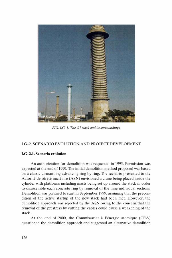
126
I.G–2. SCENARIO EVOLUTION AND PROJECT DEVELOPMENT
I.G–2.1. Scenario evolution
An authorization for demolition was requested in 1995. Permission wasexpected at the end of 1999. The initial demolition method proposed was basedon a classic dismantling advancing ring by ring. The scenario presented to theAutorité de sûreté nucléaire (ASN) envisioned a crane being placed inside thecylinder with platforms including masts being set up around the stack in orderto disassemble each concrete ring by removal of the nine individual sections.Demolition was planned to start in September 1999, assuming that the precon-dition of the active startup of the new stack had been met. However, thedemolition approach was rejected by the ASN owing to the concern that theremoval of the prestress by cutting the cables could cause a weakening of thestack.
At the end of 2000, the Commissariat à l’énergie atomique (CEA)questioned the demolition approach and suggested an alternative demolition
FIG. I.G–1. The G1 stack and its surroundings.

127
solution using explosives to topple the stack, allowing a shorter work period.On 26 April 2001 the document incorporating the safety options for this newdemolition method was sent to the ASN. An additional revision to thedemolition approach proposed, and ultimately chosen, consisted of topplingthe stack by rotation around a hinge placed under the south foot of the tripodbase. The toppling plan consisted of the sawing of the south foot of the stackbase and the destruction of the other two feet by explosives.
The advantages of the classic deconstruction method were:
— Little dust generation;— Immediate removal of waste products;— A known and tested method.
The disadvantages of the classic deconstruction method were:
— Need for working at heights;— Use of tools at heights, with the risk of their being dropped;— Difficulties in releasing the barrel prestress;— Long work period;— Implementation of the work activities in proximity to operational
facilities;— Risk of uncontrolled fall.
The advantages of the toppling method were:
— No need for working at heights;— Absence of tools at heights;— Short work period (except for waste management).
The disadvantages of the toppling method were:
— Risk of stack falling in the wrong direction;— Risk of projectiles from concrete during the toppling;— Generation of 1 t of dust;— Need for waste management at the end of the toppling;— Generation of vibrations;— More media coverage.
128
I.G–2.2. Project development
The demolition of the G1 stack by explosives was initiated with the ANS,on 26 April 2001, on the basis of the presentation of the safety optionsdocument.
The G1 stack project progressed as follows:
— Completion of safety studies made explicit in the safety optionsdocument concerning the environmental impact (dust contamination andvibrations), modelling of the toppling, management of generated wastes,and interfaces with facilities and service networks;
— Completion of a project risk analysis;— Securing work (foot of the stack and flues);— Establishment of an operational command unit;— Preparatory work for the toppling;— Bringing the stack down;— Management of the waste produced.
I.G–3. RELATIONS WITH THE NUCLEAR SAFETY AUTHORITIES
The qualified authority for nuclear safety for the Marcoule site is thedirector for the safety and radioprotection of nuclear facilities concerned withnational defence. The Institut de radioprotection et de sûreté nucléaire (IRSN)provides technical support and advice.
I.G–3.1. Milestones
The main activities leading to securing of the permission for demolitionare listed in Table I.G–1.
I.G–3.2. Safety principles
I.G–3.2.1. Normal design basis
The normal design basis corresponded to the stack falling along a south–north axis passing over the two north feet and impacting along this axis on theground. Indeed, this normal condition corresponded to the stack being broughtdown intact until an inclination angle equal to or greater than 20° comparedwith the vertical was attained. Precision of the order of ±5° for the axis of thefall was planned.

129
Within the framework of defence in depth, a stack in the vicinity (lessthan 10 m away) was protected by a temporary wall. The two nuclear facilitiesoriginally connected to the stack had a provisional ventilation outlet in placeduring the demolition operation. These facilities were also brought to a safestate through removal of nuclear materials.
In order to remain within the normal design basis condition, it wasnecessary to:
(a) Keep the stack intact throughout the entire work period;(b) Limit the effects on the site of dust contamination, general contamination
and vibrations resulting from the impact of the stack fall;(c) Limit the effects on neighbouring facilities and the various services and
utilities located in the vicinity from the concrete projectiles resulting fromthe explosion, the impact of the stack falling to the ground, the blast fromthe explosion, the vibrations and dust contamination due to the impact onthe ground, and potential fires induced by the explosives.
I.G–3.2.2. Outside-of-design situation
The outside-of-design situation corresponded to a deviation from theplan of the intended fall of the stack to the extent that, if it fell to the south-eastor to the south-west, it would impact on other facilities located in its proximity.This situation could have been caused by an unforeseen wind arising after the
TABLE I.G–1. SEQUENCE OF ACTIONS LEADING TO SECURING OF PERMISSION FOR DEMOLITION
26 April 2001 Request for approval of the safety options document for the demolition of the G1 stack by toppling
11 July 2001 Approval in principle of the safety options document for the demolition of the G1 stack by toppling given by the Commission for the Safety of Laboratories and Factories
30 April 2002 Request issued for authorization to carry out preliminary work
29 July 2002 Authorization received from the Commission for the Safety of Laboratories and Factories to carry out preparatory work for the toppling of the G1 stack
9 August 2002 Request issued for authorization to carry out demolition operations by toppling the G1 stack
13 May 2003 Authorization for demolition of the G1 stack by toppling
130
countdown, and the start of sawing of the south foot. Sawing of the south footcould not commence in the event of a wind speed of greater than 10 m/s.
I.G–4. MAIN WORK PHASES
The demolition project of the G1 stack was broken down into severaldistinct phases as follows:
— Preliminary work;— Preparatory work; — Preconditioning work for the demolition;— Pre-demolition actions;— Execution of the demolition; — Post-demolition actions.
I.G–4.1. Preliminary work
Preliminary work consisted of preparing the logistics and securing thefuture worksites as well as carrying out some demolition work. The ventilationpipe connections, which were constructed of a steel core concrete pipe linkingthe two nuclear facilities located near the stack, were dismantled. Thisoperation was particularly important because the connections weighed up to 13and 5 t, respectively (Fig. I.G–2).
I.G–4.2. Preparatory work
The preparatory work authorized by the ASN involved provision ofaccess to the stack prior to the start of preliminary work for the toppling, andprior to the start of work for the implementation of the provisional ventilationoutlets.
The work carried out on the stack during this phase included discon-necting the flues on the base plate of the stack, dismantling the internal metallicstructures and removing the concrete filling between the feet (Fig. I.G–3).
I.G–4.3. Preconditioning work for the demolition
The preconditioning work phase covered all the actions to control the fallof the stack and the consequences of deviation from the plan. These were

131
FIG. I.G–2. Removal of the ventilation piping.
FIG. I.G–3. Demolition of the filling between the stack feet.

132
critically important to the success of the project. All operations linked to thetoppling of the stack had been authorized by the ASN.
The role of the bearing device of the stack was to control the angle of fallof the stack. The selected approach employed a hinge made up of two lowercradles and a steel axis as a pivot. The cradles were placed respectivelyunderneath the south-west and the south-east tympanums (supportingconcrete facades of the stack base). The positioning of this hinge and themechanical properties of the installations and equipment involved in thetoppling formed the essential elements controlling the success of the operation.The work required on the hinge (Fig. I.G–4) involved:
— Consolidation of a solid mass of coarse concrete at the foot of the stack;— Reinforcement of the concrete with 17 micro-piles;— Creation of the two lower solid support masses for the hinge and a longi-
tudinal connecting beam;— Fitting of the pivot;— Creation of the upper masses and reinforcement of the two stack
tympanums;
FIG. I.G–4. Consolidation of the foot of the stack with a solid mass of coarse concrete,support masses and hinges.

133
— Fitting of metallic support beams to reinforce the base plate of the stack;— Drilling of the feet for placement of explosives (Fig. I.G–5);— Creation of a ‘mattress’ (shock absorber) (Fig. I.G–6).
The details of the hinge construction are provided in Ref. [I.G–1].
I.G–4.4. Pre-demolition actions
I.G–4.4.1. Organizing the toppling
It was decided to create an operations and command unit jointly run byCOGEMA and the CEA whose general role was to organize the follow-up ofthe preparatory phase, the demolition phase and the post-demolition actions,including the safe startup of the facilities.
I.G–4.4.2. Actions prior to demolition
The operations and command unit managed the interfaces of all actionspreceding the demolition. The critical steps in the pre-demolition activity wereas follows:
— Receipt of explosives; — Securing the zones;
FIG. I.G–5. Drilling of the stack feet before blasting.

134
— Following weather reports;— Installation of explosives and protecting the charged supports;— Implementation of protection for neighbouring installations and equipment;— Sensor fitting of installations and equipment;— Cutting of the south foot (Fig. I.G–7).
I.G–4.5. Execution of the demolition
Figure I.G–8 shows the breaking of the stack during toppling. Figure I.G–9shows the site and the stack after the fall.
I.G–4.6. Post-demolition actions
The post-demolition actions consisted of:
— Verifying that the stack had been toppled in accordance with the plan;— Confirming that facilities and support networks had not been damaged;— Restarting the various facilities and installations.
FIG. I.G–6. Construction of the mattress (shock absorber).
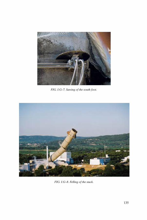
135
FIG. I.G–7. Sawing of the south foot.
FIG. I.G–8. Felling of the stack.

136
I.G–5. TOPPLING FEEDBACK
I.G–5.1. Pre-toppling
I.G–5.1.1. Fall of the stack
It was important to guarantee the angle of the stack fall, and also to limitthe breaking of the barrel during the toppling in order to limit the risk ofimpacts on neighboring facilities. Preliminary analyses demonstrated that ring15 (level 63.8 m) was likely to burst owing to the cylinder’s being bent duringthe toppling. In addition, a headwind of 10 m/s at the time of the toppling hadto be taken into account.
The stack’s predicted path during the toppling was studied in order todetermine the best trade-off between the cylinders’ rigidity during the fall andthe risk of reverse movements due to a headwind.
The analysis allowed the pivot’s position to be defined. It was installed at1.5 m on the stack. With this configuration the rigidity of the cylinder wasensured until an angle of 21° was reached.
I.G–5.1.2. Cutting the south foot of the stack
This operation was considered the most delicate and critical of alloperations during the toppling of the G1 stack. Indeed, it was an irreversible
FIG. I.G–9. Stack and site after the fall.

137
operation, since once the foot had been cut, the stack would be in a weakenedstate (with the prestressed cables cut). For this reason, it was envisaged that thesouth foot would be cut at the last moment, meteorological conditionspermitting (wind speed lower than 10 m/s and assurance of stable weatherconditions).
Work proceeded very well. At the end of the first cutting phases, a loudsound was noted that was probably due to the transfer of the load to the hinge.The cutting was completed in 8 hours to meet the ASN time limit of 12 hoursbetween the start of the cutting of the south foot and the toppling.
I.G–5.2. Verification of the fall
The kinetics of the toppling of the G1 stack were recorded on the basis ofa signal from the acoustic and vibration sensors.
Photographs were taken every 0.5 s and a video cassette was prepared aswell [I.G–2].
During toppling the cylinder split into two distinct parts below ring 15 asenvisioned. The angle at which the cylinder broke could be observed fairlyaccurately. The analysis thus demonstrated that the stack’s path during topplingcorresponded to predictions. The movement kinetics and the rupture mode ofthe barrel concurred with the results of the simulation calculations.
I.G–5.3. Vibrations
The vibrations and earth movements generated by the impact of the stackwere weaker than the simulation study values by a factor of 2 to 4. No damagewas noted at the end of the toppling operation.
I.G–5.4. Detonation effects
As indicated by detonation studies, there was no damage to windows.
I.G–5.5. Results of radiological measurements
During the two hours following the demolition, the radiologicalprotection service carried out radiological measurements. The measurementsconfirmed that there were no detectable levels of radioactivity, and access tothe site was reopened.

138
I.G–5.6. Meteorology
The radiological protection service observed Metéo France data for onemonth preceding the demolition. The data for the three days before thedemolition and on the day of the demolition provided some assurance thatthere would be no change in wind speed and direction. The analysis consistedof defining the procedures for the toppling operation and of ensuring thecoherence of these procedures with the data actually collected on the Marcoulesite. These elements were presented to the ASN.
The meteorological data conformed to the planning criteria for cuttingoperations of the south foot. The forecasts established on 18 July 2003 for thefollowing day predicted anticyclonic conditions with a weak gradient withgentle breezes resulting in a weak northerly wind of 4 to 10 km/h between 5.00and 8.00 a.m.
I.G–6. WASTE MANAGEMENT
The CEA initially intended to store the waste in the flues of the G1 backend circuit. However, with the opening of the new storage centre for very lowlevel waste at the Centre de stockage des déchets très faiblement actifs(CS TFA), concrete waste from the G1 stack was authorized for transport tothe new centre.
The removal pathways were as follows:
— Concrete rubble to the CS TFA beginning in October 2003;— Conventional waste to the centre for separation (concrete, metal,
prestressing cables, geotextiles);— Metal waste to the CS TFA in 2004 (piping, deflector, internal steel
components).
I.G–7. CONCLUSIONS
This annex has presented the main stages of the demolition of the G1stack by toppling.
The initial proposal to the regulatory authorities was to demolish thestack by segmentation using cranes and work platforms. The review processresulted in an alternative proposal to remove the stack by toppling, which wasthe method ultimately selected.

139
The demolition project for the toppling of the G1 stack was started in2001 with the presentation of selected safety options documents to the ASN,which were subsequently approved. On 19 July 2003 at 7.05 a.m., the G1 stackwas successfully brought down by toppling in accordance with the demolitionplan.
REFERENCES TO ANNEX I.G
[I.G–1] BECKER, C., SOUBIROU, P., GENELOT, G., Demolition of the G1Chimney at Marcoule by Toppling, Technical Note, Rep. CEA/DDCO/SPRO2003/001, CEA, Paris (2003).
[I.G–2] COGEMA–CEA, La disparition d’un symbole, video cassette, CEA, Paris(2003).
140
Annex I.H
OPTION FOR THE TEMPORARY REPLACEMENT OF THE GÖSGEN NPP STACK TO ACCOMMODATE CONSTRUCTION OF
THE WET STORAGE BUILDING FOR SPENT FUEL
I.H–1. INTRODUCTION
Gösgen NPP in Switzerland decided to construct a separate building onthe site of the NPP to house a pool for the storage of spent MOX and highburnup fuel. The construction area adjacent to the auxiliary building offerslimited space in a triangular shape, owing to the location of the plantventilation exhaust stack (Fig. I.H–1) relative to the plant fence.
It was anticipated that these geometric conditions could complicatefoundation work for the new storage building. Vibrations arising from insertionof in-ground steel slit walls (required to stabilize the excavation for the newbuilding foundation) were expected to impact the stack foundations.
I.H–2. PROPOSED SOLUTION
During the conceptual design of the storage facility one solutionproposed to avoid these potential impacts was to replace the stack with atemporary structure in a new location for the construction phase of the storagebuilding. This would then allow the building to be enlarged, simplifying itsstructure and layout and facilitating the foundation work. Ultimately thepermanent stack would then be constructed on top of the new storage building.
I.H–2.1. Stack dismantling proposal
(a) Stack dimensions and features
The Gösgen NPP stack is a 99 m high concrete construction of cylindricalshape reinforced with about 75 t of rebar. The mean inner diameter is 5 m, witha wall thickness of 40 cm and an inner surface area of about 1500 m2. The totalmass of concrete is 800 t.

141
(b) Dismantling method
The basic approach proposed for the dismantling is a proven methodfrequently applied to conventional stack demolition. It comprises locating acaterpillar on top of the stack equipped with concrete fragmentation toolswhich permit fragmentation of the stack walls. The resulting debris is allowedto fall into the interior of the stack.
Taking into account the fact that the demolition work was to beperformed on a site with an NPP under full power, several measures were
A
AWet Storage
Building
Stack
Railway
FIG. I.H–1. Plan view of Gösgen NPP.

142
necessary to convert the conventional dismantling approach to one which couldaccommodate the enhanced safety requirements of an NPP site (for example,avoiding the spread of debris outside the stack is achieved by arranging thecaterpillar in a tent sliding down the outside of the stack as the work proceeds).
In addition, the interior of the stack was to be maintained at belowatmospheric pressure. To minimize the amount of radioactive waste, thepotentially contaminated inner walls of the stack would be decontaminated byconcrete milling prior to the demolition of the stack. The plan includedcollection of fragmentation debris in the base of the stack.
(c) Cost estimates
The dismantling costs were estimated at €250 000 over a project durationof eight weeks. The new concrete stack located on top of the new storagebuilding was estimated to cost €1 200 000, including €250 000 for the temporarysteel stack.
I.H–3. LICENSING
The advantages of this proposal were recognized by the engineersproposing the solution as well as by the utility. Informal discussions with thelicensing authority revealed that this approach would not be approved. Thereason was that the time period of one year during which the temporary stackwould operate under full power of the reactor was considered to be too long.The authority also indicated concern over the lack of experience with stackdismantling in the vicinity of the reactor building, and the plans were thereforedropped.
I.H–4. PROGRESS OF STACK DISMANTLING TECHNOLOGIES
In the meantime, foundation work for the wet storage building has beenin progress. The original plant stack remains in position but is carefullyscrutinized with respect to its stability. Any stack deviation from the verticalaxis towards the excavation area of the new building would be a reason toreconsider the proposal, which is considered by the utility as the backupsolution.
The state of the art of dismantling of conventional stacks was reviewed,looking for applications in the nuclear area. It was recognized that there havebeen remarkable advances in facilitating demolition of stacks which reduce

143
risks to adjacent facilities and which are more reliable and more efficient thanwas the case in the past.
A German enterprise [I.H–1] is now offering demolition services forreinforced concrete stacks based on top-down segmenting through the use ofdiamond circular saws.
The new approach uses a self-climbing device carrying the sawingmachine; the device is capable of climbing down the inside of the stack stepwiseafter cutting each segment. Thus at the end of the whole procedure theclimbing saw has arrived at the bottom of the stack and all segments of thestack have been removed.
The operation is either crane or helicopter supported. It results indismantling that is much cleaner and nearly noiseless compared withfragmenting the concrete through top-down breaking.
The climbing machine comprises a lower and an upper platformconnected by a vertical mast along which the platforms can slide. Each of theplatforms is equipped with four drilling machines capable of drilling holes intothe wall of the stack. Both platforms have four hydraulically driven bolts whichare anchored into the holes. The upper platform carries two sawing machines.
The climbing machine is inserted into the stack from above by a crane ora helicopter. The lower platform drills four holes and fixes itself to the walls ofthe stack. Then the same procedure is repeated at the upper platform. Theupper stack section is attached to the crane. The circular saws then cut the wallof the stack, producing one cylindrical section which is removed from itsposition by the crane.
The climbing down operation continues by shifting the lower platformdownward along the mast, drilling new holes and reattaching the platform tothe stack wall. The upper platform moves downward in the same way, fixingitself to the stack wall. The cutting procedure is then repeated.
The size and weight of the stack rings removed depend on the carryingcapacity of the crane or helicopter.
The principle of the sequence of these operations is shown in Fig. I.H–2.Figure I.H–3 and Fig. 16 of the main text show the application of the
climbing saw for the demolition of a non-nuclear stack at a local district heatingplant.
To apply the method to contaminated stacks of nuclear facilities, theworkplace can be housed in a tent migrating downward with the climbingmachine to control any environmental releases.
The section of stack to be removed can be wrapped in plastic sheetingprior to removal, preventing the spread of contamination. Further size
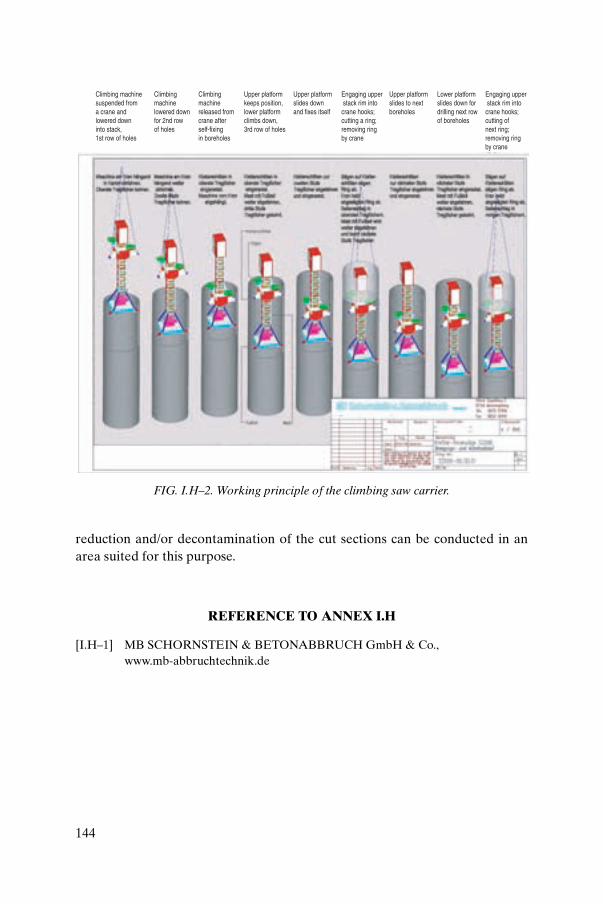
144
reduction and/or decontamination of the cut sections can be conducted in anarea suited for this purpose.
REFERENCE TO ANNEX I.H
[I.H–1] MB SCHORNSTEIN & BETONABBRUCH GmbH & Co., www.mb-abbruchtechnik.de
Climbing machinesuspended froma crane andlowered downinto stack,1st row of holes
Climbing machinelowered downfor 2nd row of holes
Climbing machinereleased fromcrane afterself-fixingin boreholes
Upper platformkeeps position,lower platformclimbs down,3rd row of holes
Engaging upper stack rim intocrane hooks;cutting a ring;removing ringby crane
Upper platformslides downand fixes itself
Upper platformslides to nextboreholes
Lower platformslides down fordrilling next rowof boreholes
Engaging upper stack rim intocrane hooks;cutting ofnext ring;removing ringby crane
FIG. I.H–2. Working principle of the climbing saw carrier.

145
FIG. I.H–3. View of the climbing sawing machine.

.

147
Annex II
LESSONS LEARNED
The following examples present lessons learned, some brief technicaldetails of each decommissioning project and a description of the problemsencountered. The situations described illustrate typical difficulties that arise inthe planning or implementing of a stack decommissioning project. Theinformation presented is not intended to be exhaustive. The reader isencouraged to evaluate the applicability of the lessons learned to his or herspecific decommissioning project.
II–1. STRUCTURAL STABILITY
Problem
Preparation of the WR-1 ventilation stack for a lengthy (50 year) decom-missioning deferment period included financial considerations relating to theemergency core cooling water storage tank located at the top of the structure.Winter heating costs alone added a significant burden to the maintenance costsof the deferment period.
Accordingly, a decision was made to empty the tank but to retain thestack in operation to meet the reactor building ventilation control require-ments. However, soon after removal of the water, it was noted that thestructure swayed visibly during high wind conditions. A review of the designrecords revealed that the mass of water in the tank was integral to maintainingthe structural stability of the stack. Therefore the tank was refilled with waterand the increased operating cost remained a project issue.
Solution
An analysis of ventilation requirements for the WR-1 reactor building forthe deferment period showed that the original stack height of 46 m was notnecessary to meet environmental release requirements. Plans were developedto assess the impact of removing the storage tank from the stack, whichresulted in tank removal and elimination of future water management costs.
148
Lesson learned
The simple approach to managing deferment period costs indicated thatsimply removing the water from the tank provided an inadequate solution. Infact a more detailed assessment of the stack design was necessary to ensure thatthe operational safety of the structure could be maintained for the overalldeferment period.
II–2. ASBESTOS GASKETS IN PIPING1
Problem
The unexpected discovery of asbestos in gasket material in the facilitypiping highlighted a serious problem during the recent decommissioning of areactor facility at the Idaho National Engineering and EnvironmentalLaboratory. Fortunately, the problem was discovered before the building wasdismantled, and corrective actions were taken.
As the Experimental Organic Cooled Reactor (EOCR) building wasbeing prepared for decommissioning, an investigation/characterization wasconducted to determine the amount and location of all asbestos-containingmaterials within the facility. After identifying the location and amounts of thismaterial, it was removed and disposed of in preparation for the explosivedemolition of the building. The building had also been previously radiologicallydecontaminated. The plan was to use explosives to dismantle the extensivepiping system at the same time that the building itself was dismantled. Duringthe asbestos removal process it was discovered that many of the pipescontained asbestos type gaskets, which would have been subjected to highexplosives during the demolition process. This could potentially have resultedin the release of airborne asbestos fibers, which would have resulted in anunacceptable environmental impact.
Solution
The dismantling schedule was delayed while all flanges were disas-sembled and the gasket material was removed.
1 Although not directly relevant to stack dismantling, this example proves thatinsufficient characterization of asbestos can be a serious problem in stack dismantling(see also Section II–3).

149
Lesson learned
Asbestos-containing materials can occur in unexpected places and a greatdeal of care must be exercised to identify all sources of this material beforeplanning demolition projects to avoid undue delay.
II–3. STACK CHARACTERIZATION PLANNING
Problem
There was uncertainty concerning the possibility of asbestos beingpresent in the gilsonite coating on the interior of the Mound facility stack. Theoriginal characterization included specific metals, pesticides and herbicides,and volatile and semivolatile organic analytes. Asbestos sampling was notincluded in the original characterization. The presence of asbestos would havecomplicated the stack demolition and required significant additional safetymanagement.
Solution
An additional asbestos sampling and analysis campaign was required thatentailed additional cost and delay. However, the absence of asbestos wasconfirmed.
Lesson learned
When planning stack characterization, it should be ensured that allpotential contaminants and hazardous materials are considered in the samplingcampaign. Overlooking key materials can lead to significant additional cost anddelay.
II–4. PERSONNEL CONSIDERATIONS
Problem
The in-house labour force at the Mound facility stack resisted working inthe base of the stack to clear contaminated debris. Working within the confinedspace and less controlled environment of the stack was new to the workforce.

150
Workers used sick and vacation leave to avoid the work and the one-day tasktook two weeks to complete.
Solution
Supervisory personnel, through employee communications and accompa-niment of workers into the stack, successfully identified a team of workers tocomplete the task.
Lesson learned
It should not be assumed that existing decommissioning labour teams willreadily adapt to new or changing working environments.
II–5. STACK CHARACTERIZATION ANALYSIS
Problem
In characterizing the Mound facility stack, the assumption was that thehighest contamination would be found at the ventilation impingement point.Accordingly, representative sampling was carried out by selecting four sampleareas and identifying only the impingement point sample for full, detailedisotopic analysis. Analysis proved the assumption false.
Solution
Fortunately the analysis data were adequate to make the argument thatisotopic ratios were consistent throughout the stack, allowing scaling of thedata to support the demolition and compliance with the waste acceptancecriteria for the site.
Lesson learned
Assumptions for selecting the highest contamination area in difficultstack access areas can lead to unexpected problems. Ideally the highestcontamination area would be confirmed by internal screening or, as aminimum, by screening the collected samples prior to conducting detailedanalysis. Screening is a relatively quick and inexpensive way of verifyingassumptions.

151
II–6. PUBLIC ISSUES AND CONCERNS
Problem
The removal of site stacks that have become historic landmarks can causeheightened public concern from several perspectives. One is resistance to theremoval of an object that has become historically significant or that hassocioeconomic implications. A second concern focuses on the safety andenvironmental impacts of the actual demolition.
Solution
Generally public concerns can be mitigated by an early public consul-tation programme. It is important to carry out comprehensive communicationon the reasons for removal and on how safety to local residents and theenvironment will be maintained.
Lesson learned
Projects like stack demolition that are highly visible should establish earlyand comprehensive public communications to manage, and hopefully alleviate,public concerns.
II–7. DISMANTLING EQUIPMENT
Problem
For any nuclear decommissioning project, the required equipment is notalways readily available. To design and manufacture bespoke, customequipment is costly, time consuming and not always successful.
Solution
The solution is to adapt standard, off-the-shelf equipment to nuclearapplications. For the Windscale Pile stack decommissioning, using a fork-lifttruck on its side was considered to remove insulation boxes from the inside ofthe stack. Although this was not directly applied, it promoted the idea of usingfork-lift truck forks mounted on a mobile excavator to carry out this task.

152
Lesson learned
The nuclear decommissioning industry can benefit from looking toother industrial applications to adapt existing proven technology to nuclearapplications.
II-8. STACK DECONTAMINATION
Problem
Manual scabbling techniques were employed to remove small areas ofcontamination during decontamination of the Windscale Pile stacks. Becausecontamination cannot be seen, this often led to arguments between healthphysics technicians and decommissioning operatives, and to rework.
Solution
Health physics technicians used spray paint to identify areas to bescabbled to make an area of contamination visible. Once the paint had beenremoved, the area had demonstrably been decontaminated. A final radiologicalsurvey confirmed successful decontamination.
Lesson learned
Simple ideas and solutions are often the most effective. In this caseapplying paint identified the work area and provided demonstrable completionof the work.
II–9. PROTECTION OF ADJACENT FACILITIES
Problem
Many sensitive buildings that are occupied and that contain nuclear andprocess plant are located below the Windscale Pile stacks. Debris or equipmentdropped from the stack could penetrate the roof and cause serious injury orcatastrophic damage.

153
Solution
It was recognized that it would be impossible to make the buildingsimpenetrable for all objects. It was therefore decided to limit the weight ofitems used outside the edge of the stack to 25 kg (the weight of a 21 ft (7 m)scaffold tube), and a protective cover of timber decking was placed above thebuildings to limit damage potential.
Lesson learned
It is not always possible to remove a hazard or problem completely, but acompromise can often be found through a combination of protection andlimiting hazard potential.
II–10. SCAFFOLD ACCESS
Problem
Because of the size of the Windscale Pile stacks, it was considered thatconventional scaffolding would not meet access requirements and that astructural access system was required, but because of a 25 kg weight limitimposed owing to the proximity of adjacent facilities (see Section II–9), thissolution was not possible.
Solution
Pressed steel lightweight sections of scaffolding equipment, often used incivil engineering construction for temporary works, were evaluated and foundto meet project access and weight restrictions.
Lesson learned
Risk mitigation strategies can have significant effects on other parts of theproject and may require a degree of ingenuity to overcome problemseffectively.

154
II–11. HIGH ALPHA SURFACE CONTAMINATION
Problem
Areas of high alpha contamination create personnel hazards and canmake disassembly solutions cumbersome.
Solution
At the Mound facility stack, a specialist contractor, EncapsulationTechnologies, developed a fogging technology to apply an aerosol coatinguniformly over the contaminated surface. The application was achievedwithout invasively entering the contaminated zone. Loose surfacecontamination was reduced by a factor of over 1000.
Lesson learned
New technologies should be considered while a project is in the designphase. The act of disassembling the stack plenum was greatly simplified, withminimal personal protective equipment required for the workers.
155
CONTRIBUTORS TO DRAFTING AND REVIEW
Becker, C. Commissariat à l’énergie atomique, France
Bennett, A.J. United Kingdom Atomic Energy Authority, United Kingdom
Cowper, S. British Nuclear Fuels, United Kingdom
Helbrecht, R.A. Private consultant, Canada
Laraia, M. International Atomic Energy Agency
Leister, P. COLENCO, Switzerland
Maul, G.F. Private consultant, United States of America
Meservey, R.H. Idaho National Engineering and Environmental Laboratory, United States of America
Orsini, A. Ente per le Nuove Technologie, l’Energia e l’Ambiente, Italy
Reisenweaver, D. International Atomic Energy Agency
Visagie, A.L. Nuclear Energy Corporation of South Africa, South Africa
Consultants Meetings
Vienna, Austria: 17–21 February 2003, 23–27 February 2004,4–7 January 2005

INTERNATIONAL ATOMIC ENERGY AGENCYVIENNA
ISBN 92–0–104505–0ISSN 0074–1914
Nearly all nuclear installations utilize stacks to discharge ventilation air, as well as gases and fumes, from contaminated areas to the environment. Over a service lifetime that can span decades, stacks may become contaminated as a result of the deposition of radioactive substances, e.g. aerosols, on stack surfaces. In the longer term, this is a serious decommissioning issue. The contamination may be difficult to remove, depending on the operating conditions and the chemical and physical environment over time. In addition, the physical logistics of stack dismantling may be complex, for example the difficulty of severing concrete at height. Relevant aspects of stack dismantling include project planning and management, health and safety, and the management and disposal of the resulting waste. It can be assumed that generic decontamination/dismantling technologies would also apply to these bulky components, but such treatment disregards a number of specific physical and radiological characteristics that make stack decommissioning a unique project. This report reviews and consolidates the worldwide experience available on the technical and planning aspects of stack decommissioning.


![scientificreports.440 Open Access Scientific Reports · 2014-05-19 · Open Access Scientific Reports. ... testicular function after experimental testicular hypogonadism [8] ... IAP](https://static.fdocuments.us/doc/165x107/5f09f2a17e708231d42945fa/scientificreports440-open-access-scientific-reports-2014-05-19-open-access-scientific.jpg)


