Technical Report UDC 629 . 11 . 011 : 62 - 478 : 539 . 42 ...
6
NIPPON STEEL TECHNICAL REPORT No. 122 NOVEMBER 2019 - 93 - UDC 629 . 11 . 011 : 62 - 478 : 539 . 42 Technical Report Stiffness Increase and Weight Reduction Based on Stiffness Evaluation Techniques Takeshi KAWACHI* Naoki KIMOTO Yusuke TSUNEMI Abstract Deformation of a structure mainly composed of thin metal sheets comprises stretch/com- press, shear, and bend. The bend component largely reduces the stiffness by reduction of thickness. In this paper, the bending factor, which evaluates how much plate bending defor- mation occurs in a structure under elastic deformation and is obtained as the power index of the approximation of stiffness as a power of the thickness increase rate, is induced. Ad- ditionally, an example of optimization of thickness distribution in a vehicle body using the bending factor for individual parts is introduced. An example of realizing a lightweight truss structure for a suspension member is also introduced. From the bending factor evalu- ation, it is shown that a suspension member with a truss structure is structurally superior to conventional structures. 1. Preface Recently, requirements for weight reduction of automobiles have been made more stringent. In some examples, low-density metals like aluminum or fiber-reinforced plastics represented by CFRP are used for vehicle bodies or chassis parts to achieve lightweight vehi- cles. In steel materials, use of high strength/thin material (high-ten- sile-strength material) contributes to weight reduction and collision safety of automobiles. 1) However, the vehicle body is a structure in which thin sheets are formed and assembled. Use of thin steel sheets may cause concerns of low stiffness of vehicle bodies or chassis parts, low handling quality of vehicles (steering stability or driving comfort), and increase of noise and vibration. 2–9) To this end, actions that increase vehicle body stiffness through improvement of struc- ture or joining method have been reported mainly by automobile manufacturers. 10–13) This paper proposes the bending factor as the evaluation index based on deformation modes for the parts, vehicle body, and suspen- sion members constituting a vehicle and are responsible for body stiffness, to evaluate the structures of vehicle bodies and suspension members. In addition, this paper introduces the method of selecting important parts and areas for review for the purpose of improving the stiffness of structures by calculating the bending factor for each part or area constituting the structure under load, and examples of applying the method to vehicle bodies are introduced. For the front suspension member of front-engine-/front-drive (hereinafter referred to as FF) vehicles, the structure is optimized in view of structural mechanics and evaluated by the bending factor. For the front sus- pension member with an optimized structure and the suspension member with a conventional structure, stiffness and weight for lat- eral force generated during vehicle turning are compared. 2. Stiffness Evaluation Method Focused on Defor- mation Modes 2.1 Stiffness of structure Vehicle bodies or chassis parts have beam parts with a closed cross section and panel-like parts with an open cross section. There- fore, when the vehicle body is subject to elastic deformation with load received under specified constraints, deformation of both the closed cross-section beam and the flat sheet is generated. Deforma- tion of the flat sheet is classified into bending, stretch (compression), and shear (torsion). Similarly, deformation of the overall closed cross-section beam is classified into bending, stretch (compression), and torsion. However, focusing on deformation modes of the sheets constituting frames that have closed cross sections, stretch (com- pression) and shear should be considered. Stiffness against stretch (compression), shear, and bending load of the flat sheet is propor- * Senior Researcher, Dr.Eng., Integrated Steel-Solution Research Lab., Steel Research Laboratories 20-1 Shintomi, Futtsu City, Chiba Pref. 293-8511
Transcript of Technical Report UDC 629 . 11 . 011 : 62 - 478 : 539 . 42 ...
NIPPON STEEL TECHNICAL REPORT No. 122 NOvEmbER 2019
- 93 -
UDC 629 . 11 . 011 : 62 - 478 : 539 . 42Technical Report
Stiffness Increase and Weight Reduction Based on Stiffness Evaluation Techniques
Takeshi KAWACHI* Naoki KIMOTOYusuke TSUNEMI
AbstractDeformation of a structure mainly composed of thin metal sheets comprises stretch/com-
press, shear, and bend. The bend component largely reduces the stiffness by reduction of thickness. In this paper, the bending factor, which evaluates how much plate bending defor-mation occurs in a structure under elastic deformation and is obtained as the power index of the approximation of stiffness as a power of the thickness increase rate, is induced. Ad-ditionally, an example of optimization of thickness distribution in a vehicle body using the bending factor for individual parts is introduced. An example of realizing a lightweight truss structure for a suspension member is also introduced. From the bending factor evalu-ation, it is shown that a suspension member with a truss structure is structurally superior to conventional structures.
1. PrefaceRecently, requirements for weight reduction of automobiles have
been made more stringent. In some examples, low-density metals like aluminum or fiber-reinforced plastics represented by CFRP are used for vehicle bodies or chassis parts to achieve lightweight vehi-cles. In steel materials, use of high strength/thin material (high-ten-sile-strength material) contributes to weight reduction and collision safety of automobiles. 1) However, the vehicle body is a structure in which thin sheets are formed and assembled. Use of thin steel sheets may cause concerns of low stiffness of vehicle bodies or chassis parts, low handling quality of vehicles (steering stability or driving comfort), and increase of noise and vibration. 2–9) To this end, actions that increase vehicle body stiffness through improvement of struc-ture or joining method have been reported mainly by automobile manufacturers. 10–13)
This paper proposes the bending factor as the evaluation index based on deformation modes for the parts, vehicle body, and suspen-sion members constituting a vehicle and are responsible for body stiffness, to evaluate the structures of vehicle bodies and suspension members. In addition, this paper introduces the method of selecting important parts and areas for review for the purpose of improving the stiffness of structures by calculating the bending factor for each part or area constituting the structure under load, and examples of
applying the method to vehicle bodies are introduced. For the front suspension member of front-engine-/front-drive (hereinafter referred to as FF) vehicles, the structure is optimized in view of structural mechanics and evaluated by the bending factor. For the front sus-pension member with an optimized structure and the suspension member with a conventional structure, stiffness and weight for lat-eral force generated during vehicle turning are compared.
2. Stiffness Evaluation method Focused on Defor-mation modes
2.1 Stiffness of structureVehicle bodies or chassis parts have beam parts with a closed
cross section and panel-like parts with an open cross section. There-fore, when the vehicle body is subject to elastic deformation with load received under specified constraints, deformation of both the closed cross-section beam and the flat sheet is generated. Deforma-tion of the flat sheet is classified into bending, stretch (compression), and shear (torsion). Similarly, deformation of the overall closed cross-section beam is classified into bending, stretch (compression), and torsion. However, focusing on deformation modes of the sheets constituting frames that have closed cross sections, stretch (com-pression) and shear should be considered. Stiffness against stretch (compression), shear, and bending load of the flat sheet is propor-
* Senior Researcher, Dr.Eng., Integrated Steel-Solution Research Lab., Steel Research Laboratories 20-1 Shintomi, Futtsu City, Chiba Pref. 293-8511
- 94 -
NIPPON STEEL TECHNICAL REPORT No. 122 NOvEmbER 2019
tional to the product of Young’s modulus E and thickness t, the product of elastic shear modulus G and thickness, and the product of Young’s modulus and third power of thickness, respectively (Fig. 1). Therefore, assuming that the elastic modulus of the material is con-stant, it is considered that the stiffness of the overall vehicle body is proportional to 1 to 3 power of the thickness. In other words, if the sheet bending area is large, the stiffness of the structure under load is close to the third power of the thickness. If it is small in number, it shows that the stiffness approaches the first power of the thick-ness.
In contrast, if the material density is constant, the weight of the vehicle body is proportional to the thickness. If the thickness is re-duced without structural change for weight reduction, this indicates the possibility that the stiffness reduction rate is larger than the weight reduction rate. To use the thin high-tensile-strength steel, it is necessary to reduce sheet bending and to make a structure with stiff-ness proportional to the first power of the thickness.2.2 bending factor
As described above, the deformation mode of a general thin-sheet structure is superposition of the deformation modes shown in Fig. 1, and it is considered that the stiffness of the thin-sheet struc-ture is proportional to 1 to 3 power of the thickness. This power number of the thickness evaluates how much thin-sheet structure bending deformation occurs. However, like the vehicle body, the thickness varies depending on the area or part of the structure. Then, stiffness K is calculated when the thickness of all parts constituting the structure is changed by constant magnification α = t/t0 (where t0 is the original thickness of a part and t is the thickness after varia-tion). Using original stiffness value K0, approximation is performed as below:
K = K0 α b. (1)
Power index b at this time is defined as the bending factor. From the discussion above, the bending factor has a value of 1 to 3. In a struc-ture where the bending factor is close to 1, there is less bending and less stiffness reduction than in a structure where the bending factor is close to 3 when the thickness is reduced. In short, the smaller bending factor is, the better the structure is, in view of stiffness.2.3 Evaluation of the vehicle body structure with the bending
factorUsing a CAE model of two vehicle bodies (with a front wind-
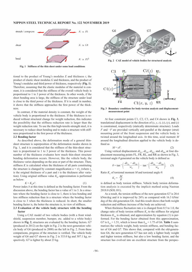
shield, suspension member, bumper, etc. added to a white body) shown in Fig. 2, structures are evaluated by the bending factors. G7 (produced in 2012) on the right in Fig. 2 is the next-generation vehi-cle body of G6 (produced in 2008) on the left in Fig. 2. From these comparisons, progress of the structure is verified. The vehicle body weight of G6 and G7 shown in Fig. 2 is 333.0 kg and 307.1 kg, re-spectively. G7 is lighter by about 23 kg.
At four constraint points C1, C2, C3, and C4 shown in Fig. 3, translational displacement in the direction of (x, y, z), (z), (y), and (z) is constrained, respectively (statically determinate structure). Loads F and −F are provided vertically anti-parallel at the damper (strut) mounting point of the front suspension and the vehicle body is twisted around the longitudinal axis. At this time, axial moment M around the longitudinal direction applied to the vehicle body is de-fined as
M = sF. (2)Using vertical displacement dzFL, dzFR, dzRL, and dzRR at four dis-
placement measuring points FL, FR, RL, and RR as shown in Fig. 3, torsional angle θ generated on the vehicle body is defined as
θ = tan−1 − tan−1 . (3)
Ratio KT of torsional moment M and torsional angle θ:
KT = (4)
is defined as body torsion stiffness. Vehicle body torsion deforma-tion analysis is executed by the implicit method using Nastran 2018.0 (SOL101).
As a result, the torsion stiffness of the new-generation G7 is 20.6 kNm/deg and it is improved by 26% as compared with 16.3 kNm/deg of the old-generation G6. And this result shows that both weight reduction and stiffness increase of the body are achieved.
When thickness fluctuation rate α is changed from 0.5 to 1.0, the change ratio of body torsion stiffness KT to the stiffness for original thickness KT0 is obtained, and approximation by equation (1) is per-formed. For the bending factor obtained from this approximation, G7 is bG7 = 1.51, which is lower than bG6 = 1.75 of G6. Table 1 sum-marizes the vehicle weight, body torsion stiffness, and bending fac-tor of G6 and G7. This shows that, compared with the old-genera-tion G6, the new-generation G7 has not only a lighter body weight and higher torsion stiffness, but also a low bending factor, and the structure has evolved into an excellent structure from the perspec-
dzFL − dzFRwF
dzRL − dzRRwR
Mθ
Fig. 1 Stiffness of the thin sheet under some load conditions
Fig. 2 CAE model of vehicle bodies for structural analysis
Fig. 3 boundary conditions for body-torsion analysis and displacement-measurement point

NIPPON STEEL TECHNICAL REPORT No. 122 NOvEmbER 2019
- 95 -
tive of torsion stiffness.2.4 Evaluation of the bending factor for each part
In this section, for further improvement of stiffness and reduc-tion of the bending factor, evaluation of the bending factor for each area or part is attempted. Each part constituting the vehicle body is selected and displacement of the node directly connected to a join-ing element (elements of spot welding, laser welding, and adhesion) obtained from the result of the body torsion stiffness analysis is ap-plied as forced displacement. Then, the bending factor for the part can be estimated from the change in the reaction force when the thickness is changed. However, it takes a significant amount of time to set the boundary conditions for each part and to prepare the mod-els. As shown in Fig. 1, using the proportional principle of each stiffness of the thin sheet to the first power of elastic modulus, the bending factor is estimated by comparing the amount of change of the vehicle body stiffness when thickness t of the target area is changed with the amount of change of vehicle body stiffness when Young’s modulus E is changed (elastic shear modulus G is also changed in proportion to E).
Assuming that a structure under load is a parallel spring system composed of N number of areas, when the stiffness of the i-th area is Ki, total stiffness Ktot is represented by the sum of stiffness Ki for each area. Assuming that the deformation amount of each area is the linear sum of the out-of-plane deformation element and in-plane de-formation element, and considering the deformation mode of the j-th area, using proportional coefficients βSj and βBj for each area,
Ktot = ∑ Ki + + −1
(5)
can be expressed. The first term and the second term in the paren-theses of the second term of equation (5) respectively shows the in-plane deformation element and the out-of-plane deformation ele-ment. Each sensitivity for Young’s modulus Ej and thickness tj of the j-th area of total stiffness Ktot is obtained as follows:
= +
= + 3 . (6)
Therefore, when only ΔEj (<< Ej) or Δtj (<< tj) are changed, change ΔKtot j of the overall structural stiffness is calculated as fol-lows:
ΔKtot j = ΔEj + Δtj
= K 2j + + + 3 . (7)
Assuming that a structure is a series spring system composed of N number of areas, the following is obtained:
ΔKtot j = K 2tot + + + 3 . (8)
If deformation of the target area is mainly in-plane deformation,
it is considered as βBj = 0. If it is mainly out-of-plane deformation, it is considered as βSj = 0. Regardless of the assumption of parallel spring or series spring,
ΔKtot j ∝
+ In-plane deformation (9)
+ 3 Out-of-plane deformation
it is estimated that the relationship above can be satisfied. From the equation above, the ratio of stiffness change when only the thick-ness is changed (ΔEj = 0) and the stiffness change when only Young’s modulus is changed (Δtj = 0) can be obtained. If the change ratio of the thickness and Young’s modulus is constant and it is Δtj/tj = ΔEj/Ej, the ratio is defined as follows:
bj = ≈ (10)
Similar to the bending factor in the previous chapter, bj serves to evaluate the bending factor of the target area.
For example, in the vehicle body under torsional deformation load, each body torsion stiffness change is obtained when Young’s modulus and the thickness of each part are changed at the same ra-tio. From the ratio of two change of stiffness, the bending factor of the target part can be obtained.
Figure 4 shows the distribution of the bending factor for each part in the body torsion stiffness of G7 shown on the right of Fig. 2. However, a part that is considered to be symmetrical is treated as one part for analysis. This shows trends that the bending factor is high at the mounting of suspension parts, frame joints, or parts with an open cross section and it is low on a frame with a closed cross section.2.5 Study of weight reduction and stiffness improvement
The previous discussion shows that reduction of the bending factor is effective for improvement of stiffness in a structure com-posed of thin-sheet formed parts. In other words, it is preferable to transfer load inside the structure with axial force (stretch and com-pression) or shear force shown in Fig. 1. Using density ρ, the ratio of stiffness K and mass m is as follows:
∝ = t b−1. (11)
When the sheet bending is reduced and the bending factor of the structure is close to 1, K/m is proportional only to E/ρ. Although E/ρ is determined by the material, it is almost constant as E/ρ = 26 × 106 m2/s2 for a metal. Making the bending factor close to 1 means that both stiffness and weight reduction are satisfied without using low-density metal such as aluminum or magnesium.
i≠j
βSj
Ej tj
βBj
Ej t 3
j
∂Ktot
∂Ej
K 2j
Ej
βSj
Ej tj
βBj
Ej t 3
j
∂Ktot
∂tj
K 2j
tj
βSj
Ej tj
βBj
Ej t 3
j
∂Ktot
∂Ej
∂Ktot
∂tjβSj
Ej tj
ΔEj
Ej
Δtj
tj
βBj
Ej t 3
j
ΔEj
Ej
Δtj
tj
βSj
Ej tj
ΔEj
Ej
Δtj
tj
βBj
Ej t 3
j
ΔEj
Ej
Δtj
tj
ΔEj
Ej
Δtj
tj
ΔEj
Ej
Δtj
tj
ΔKtot j (ΔEj = 0)ΔKtot j (Δtj = 0)
1 In-plane deformation3 Out-of-plane deformation.
Km
Et bρt
Eρ
Table 1 Performance comparison between G6 and G7 (CAE model)
Body mass[kg]
Torsion stiffness[kNm/deg]
Bending factor
G6 333.0 16.3 1.75G7 307.1 20.6 1.51
Fig. 4 bending factor distribution in the body of G7

- 96 -
NIPPON STEEL TECHNICAL REPORT No. 122 NOvEmbER 2019
To make the bending factor close to 1, specifically, bent parts of the frame that transfer load are minimized and load is transferred within the plane. In particular, at joints of frames, it is better to smoothly join the plane of one frame with the plane of the other frame without a step. If a step occurs at the frame or joint due to various restrictions, out-of-plane deformation is reduced by increase in thickness, by additional stiffness to the bulkhead, etc. In addition, it is considered that providing these measures at areas where the bending factor is high can improve stiffness while reducing increase of weight.
In the next chapter, using the study in this chapter for reference, examples of optimum thickness distribution based on the bending factor and using a truss structure for the suspension member, which is intended to transfer load with axial force, are introduced and the performance is verified.
3. Study of Increased Stiffness for vehicle bodies and Suspension members
3.1 Satisfying both weight reduction and high stiffness of vehicle bodiesBy increasing/decreasing the thickness according to the bending
factor distribution in Fig. 4, weight reduction is attempted while maintaining the body torsion stiffness of G7. Specifically, for parts with low values and small plate bending deformation, the plate thickness can be reduced thereby reducing the weight. Since the sta-tus as is reduces the stiffness, the thickness is increased for parts with high values and large plate bending deformation to compensate for the stiffness. Considering the bending factor and the part weight, after increase/decrease in thickness in the distribution shown in Fig. 5, reduction of about 5 kg (about 2%) is achieved while maintaining torsion stiffness.3.2 Satisfying weight reduction and high stiffness of suspension
membersIn this chapter, the truss structure for load transfer with axial
force shown in Fig. 6 is used for the suspension member to achieve weight reduction and stiffness maintenance. To achieve a structure in which the bending factor close to 1, the design guideline below is used. The structure has a layout with the frame arranged on the axis line joining the load input points from the lower arm or on the axis line joining a load input point and the body mounting. Additionally, the structure has a layout where the joints of the frames are smooth-ly coupled with the planes constituting frames and a layout where the engine mounting or body mounting with a large thickness is placed at joints. In this truss structure, the minimum value of the sheet thickness is 1.0 mm and the part weight is 8.3 kg.
Using the CAE model of the truss structure in Fig. 6, the stiff-ness for the load input from the lower arms is evaluated. The mate-
rial is a thin steel sheet. The evaluation results are compared with the CAE model of two suspension members shown in Fig. 7. The il-lustration on the left in Fig. 7 is the G7 suspension member com-posed of a thin steel sheet similarly, and the illustration on the right in Fig. 7 is the A3 suspension member composed of die-cast alumi-num. C-segment vehicles with common positions of the body mounting and lower arm mountings are assumed for both cases and the required stiffness is equivalent. Figure 8 shows the boundary conditions to evaluate the stiffness of the suspension member. At four body mounts C1, C2, C3, and C4, translation displacement in the (x, y, z) direction each is constrained. The suspension member is assumed to receive a lateral load through the lower arm during turn of the vehicle.
In this way, mount positions A1L, A1R, A2L, and A2R of two lower arms each at the left and right and joining points WL and WR of the left and right lower arms and knuckles are coupled with rigid beams, and a lateral load is applied to each of WL and WR. The load conditions are two types that apply lateral loads F and −F anti-parallel in the left-right direction with WL and WR and that apply lateral load F and F parallel to the left and right WL and WR. At this time, ratio KL of load F and average displacement δ of the load input points WL and WR is defined as the stiffness of the suspension
Fig. 5 Distribution of thickness change for stiffness increase and weight reduction
Fig. 6 Adoption of truss structure on suspension member
Fig. 7 CAE model of suspension member for structural analysis
Fig. 8 boundary conditions for stiffness analysis of suspension member and displacement-measurement points
NIPPON STEEL TECHNICAL REPORT No. 122 NOvEmbER 2019
- 97 -
member, which can be expressed as
KL = . (12)
Deformation analysis of the suspension member is executed by the implicit method using Nastran 2018.0 (SOL101).
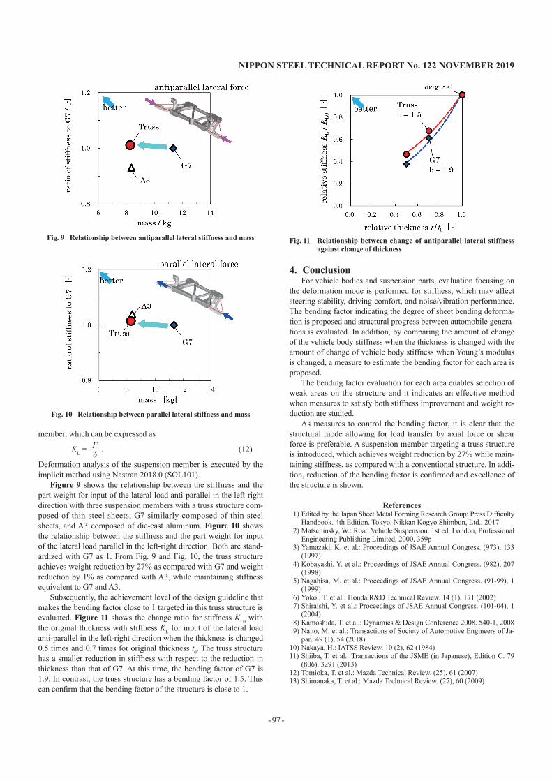
Figure 9 shows the relationship between the stiffness and the part weight for input of the lateral load anti-parallel in the left-right direction with three suspension members with a truss structure com-posed of thin steel sheets, G7 similarly composed of thin steel sheets, and A3 composed of die-cast aluminum. Figure 10 shows the relationship between the stiffness and the part weight for input of the lateral load parallel in the left-right direction. Both are stand-ardized with G7 as 1. From Fig. 9 and Fig. 10, the truss structure achieves weight reduction by 27% as compared with G7 and weight reduction by 1% as compared with A3, while maintaining stiffness equivalent to G7 and A3.
Subsequently, the achievement level of the design guideline that makes the bending factor close to 1 targeted in this truss structure is evaluated. Figure 11 shows the change ratio for stiffness KL0 with the original thickness with stiffness KL for input of the lateral load anti-parallel in the left-right direction when the thickness is changed 0.5 times and 0.7 times for original thickness t0. The truss structure has a smaller reduction in stiffness with respect to the reduction in thickness than that of G7. At this time, the bending factor of G7 is 1.9. In contrast, the truss structure has a bending factor of 1.5. This can confirm that the bending factor of the structure is close to 1.
4. ConclusionFor vehicle bodies and suspension parts, evaluation focusing on
the deformation mode is performed for stiffness, which may affect steering stability, driving comfort, and noise/vibration performance. The bending factor indicating the degree of sheet bending deforma-tion is proposed and structural progress between automobile genera-tions is evaluated. In addition, by comparing the amount of change of the vehicle body stiffness when the thickness is changed with the amount of change of vehicle body stiffness when Young’s modulus is changed, a measure to estimate the bending factor for each area is proposed.
The bending factor evaluation for each area enables selection of weak areas on the structure and it indicates an effective method when measures to satisfy both stiffness improvement and weight re-duction are studied.
As measures to control the bending factor, it is clear that the structural mode allowing for load transfer by axial force or shear force is preferable. A suspension member targeting a truss structure is introduced, which achieves weight reduction by 27% while main-taining stiffness, as compared with a conventional structure. In addi-tion, reduction of the bending factor is confirmed and excellence of the structure is shown.
References1) Edited by the Japan Sheet Metal Forming Research Group: Press Difficulty
Handbook. 4th Edition. Tokyo, Nikkan Kogyo Shimbun, Ltd., 20172) Matschinsky, W.: Road Vehicle Suspension. 1st ed. London, Professional
Engineering Publishing Limited, 2000, 359p3) Yamazaki, K. et al.: Proceedings of JSAE Annual Congress. (973), 133
(1997)4) Kobayashi, Y. et al.: Proceedings of JSAE Annual Congress. (982), 207
(1998)5) Nagahisa, M. et al.: Proceedings of JSAE Annual Congress. (91-99), 1
(1999)6) Yokoi, T. et al.: Honda R&D Technical Review. 14 (1), 171 (2002)7) Shiraishi, Y. et al.: Proceedings of JSAE Annual Congress. (101-04), 1
(2004)8) Kamoshida, T. et al.: Dynamics & Design Conference 2008. 540-1, 20089) Naito, M. et al.: Transactions of Society of Automotive Engineers of Ja-
pan. 49 (1), 54 (2018)10) Nakaya, H.: IATSS Review. 10 (2), 62 (1984)11) Shiiba, T. et al.: Transactions of the JSME (in Japanese), Edition C. 79
(806), 3291 (2013)12) Tomioka, T. et al.: Mazda Technical Review. (25), 61 (2007)13) Shimanaka, T. et al.: Mazda Technical Review. (27), 60 (2009)
Fδ
Fig. 9 Relationship between antiparallel lateral stiffness and mass
Fig. 10 Relationship between parallel lateral stiffness and mass
Fig. 11 Relationship between change of antiparallel lateral stiffness against change of thickness

- 98 -
NIPPON STEEL TECHNICAL REPORT No. 122 NOvEmbER 2019
Takeshi KAWACHISenior Researcher, Dr.Eng.Integrated Steel-Solution Research Lab.Steel Research Laboratories20-1 Shintomi, Futtsu City, Chiba Pref. 293-8511
Yusuke TSUNEMIResearcherKimitsu R & D Lab.
Naoki KIMOTONagoya R & D Lab.