Technical Report, Thermodeck
22
TermoDeck Technical Report Student Fahimeh Rezvani Matriculation Number 10019743 Module leader John B. Wood, University of Edinburgh
-
Upload
fahimehrezvani -
Category
Documents
-
view
215 -
download
0
Transcript of Technical Report, Thermodeck

TermoDeck
Technical Report
Student Fahimeh Rezvani Matriculation Number 10019743 Module leader John B. Wood, University of Edinburgh

Table of Contents Introduction ............................................................................................................................................ 4
Heavyweight Construction....................................................................................................................... 5
TermoDeck .............................................................................................................................................. 6
TermoDeck Principle ............................................................................................................................ 6
Indoor Climate Regulation ....................................................................................................................... 7
BUILDING FABRIC .................................................................................................................................... 8
Exposed Roof Construction .................................................................................................................. 8
Ceiling / Bulkhead Finishes .................................................................................................................. 9
External Wall Construction .................................................................................................................. 9
Internal Partitions ................................................................................................................................ 9
Ground floor ........................................................................................................................................ 9
Overhangs/Exposed Floors .................................................................................................................. 9
Windows & glazing performance ....................................................................................................... 10
Fixing ................................................................................................................................................. 10
Drainage ............................................................................................................................................ 10
Wire patterns .................................................................................................................................... 10
Core infill ........................................................................................................................................... 10
Benefit .................................................................................................................................................. 11
Repeat business................................................................................................................................. 11
Low energy consumption ................................................................................................................... 11
Occupant satisfaction ........................................................................................................................ 11
Low environmental impact ................................................................................................................ 12
Design flexibility ................................................................................................................................ 12
Reduced capital costs ........................................................................................................................ 12
Reduced running, operating and maintenance costs .......................................................................... 13
Storage capacity of a hollow core concrete slab..................................................................................... 13
Simulation ............................................................................................................................................. 14
Planning AND DESIGN Flexibility ............................................................................................................ 14
Performance Data: Costs and Energy Consumption ............................................................................... 15
TermoDeck Systems .............................................................................................................................. 16
The Basic TermoDeck System ............................................................................................................ 16

TermoDeck with Mechanical Cooling ................................................................................................. 16
TermoDeck with Evaporative Cooling ................................................................................................ 17
TermoDeck with Displacement Ventilation ........................................................................................ 17
TermoDeck with Switch-flow ............................................................................................................. 17
Control .................................................................................................................................................. 18
1. TermoDeck treated Hollow core units ............................................................................................ 18
2. Low energy air handling units ........................................................................................................ 18
3. Building energy management system............................................................................................. 18
Examples of the control modes of a low energy air handling unit........................................................... 19
Conclusion ............................................................................................................................................. 20
References ............................................................................................................................................ 21

Introduction As a background The TermoDeck system was developed in Scandinavia by two Swedish engineers Mr. Loa Anderson and Dr. Engelbrekt Isfält in the 1970s. After that, during the fall of 2004 the work with a project called TermoDeck Revisited began at the
division of Building Technology at the Royal Institute of Technology in Stockholm, Sweden. The project was developed due to the need of cost efficient means to reduce the use of high quality energy and to reduce the environmental impact of buildings. The TermoDeck system works in conjunction with mechanical ventilation system, simple ductwork, and low U-value materials to maximize the heat exchange between the structure and the interior environment and creates an holistic system that is quiet in operation, unobtrusive in appearance, and which provides the stable internal conditions required for most types of buildings including offices, libraries, hotels, schools, hospitals, theatres and universities. At the TermoDeck system the supply air passes through the hollow cores at low velocities, allowing prolonged contact between the air and the slabs. This enables the slabs to behave as passive heat exchange elements that release heat to, or absorb heat from, the air in the slabs. The temperature difference, between the slab and the air that exits the slab, is not more than 1 and 2 degrees Celsius. In winter, a heat recovery air-handling unit re-uses the heat generated within the building by occupants, IT equipment and lighting to pre condition the incoming fresh air. In summer, intelligent control pre cools the TermoDeck slabs over night using the lower ambient air temperatures. The slabs are purged of unwanted heat during this process to provide further coolth storage for the following day, reducing the need for mechanical cooling. The most space of my project is theatre so an alternative strategy is to use ‘active’ thermal mass systems. These are suitable for buildings with higher heat loads and more demanding cooling requirements such as lecture halls, theatres and offices. In this instance, enhanced heat transfer and thus extra cooling (up to 40 W/m2).Clearly the noise issue ruled out natural ventilation and a conventional air conditioned system would breach the low energy rule.

In addition to, TermoDeck was the only system found to satisfy the three basic rules means Low energy consumption, resistance to external noise and low maintenance. What is unique about this system is that ventilation and heating/cooling is integrated into one system. The biggest advantage of the system is the capability to store and distribute heat in the hollow core concrete elements which has a positive effect on energy use.
Heavyweight Construction In the heavyweight construction, the flow of heat is slowest through dense, once dense materials have reached their maximum internal temperature, the slow release of heat helps maintain comfortable room temperatures for a significant time after the initial heat input has been made. The thermal mass provides a relatively stable radiant temperature, so even if the air is quite warm the concrete surface will make occupants feel relatively cool. It enables higher air temperatures to be tolerated than in lighter-weight buildings, which can be subject to higher radiant temperatures resulting from warmer internal surfaces Benefit
There is a 2 – 15% saving in heating energy due to thermal mass, with a typical saving in North-European climate conditions of 10% when comparing light and heavyweight buildings.
When no cooling is used in the summer, the highest indoor air temperatures in a heavyweight building are 3 – 6 degrees lower than those in an equivalent lightweight building; thus high thermal mass can reduce the need for cooling.
Night ventilation of the buildings can decrease or prevent the use of mechanical cooling. When coupled with high thermal mass, this decreases the energy needed for cooling by up to 50%.
The combination of high thermal mass and improved air tightness can result in a 20% reduction in heating energy consumption compared with a lightweight equivalent.
There are several ways to enhance the functions as a thermal storage or thermal buffer. The first method is implemented by a famous “TermoDeck system.
Figure 1 Utilization of free energy gains according to EN ISO 13790
(simplified for this guide). The example shows that, for a given ratio of free gains to heat loss, a heavyweight building provides a higher
utilization than a lightweight building. Source : European Concrete Platform, 2007
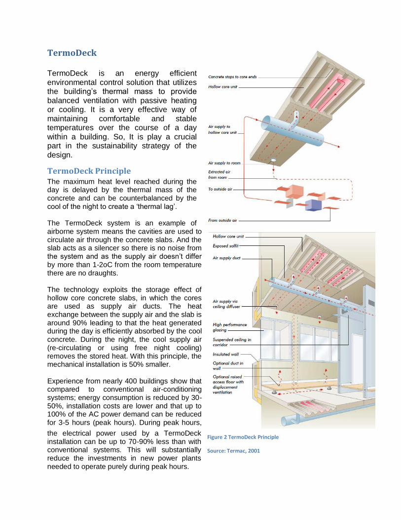
TermoDeck TermoDeck is an energy efficient environmental control solution that utilizes the building’s thermal mass to provide balanced ventilation with passive heating or cooling. It is a very effective way of maintaining comfortable and stable temperatures over the course of a day within a building. So, It is play a crucial part in the sustainability strategy of the design.
TermoDeck Principle The maximum heat level reached during the day is delayed by the thermal mass of the concrete and can be counterbalanced by the cool of the night to create a ‘thermal lag’. The TermoDeck system is an example of airborne system means the cavities are used to circulate air through the concrete slabs. And the slab acts as a silencer so there is no noise from the system and as the supply air doesn’t differ by more than 1-2oC from the room temperature there are no draughts. The technology exploits the storage effect of hollow core concrete slabs, in which the cores are used as supply air ducts. The heat exchange between the supply air and the slab is around 90% leading to that the heat generated during the day is efficiently absorbed by the cool concrete. During the night, the cool supply air (re-circulating or using free night cooling) removes the stored heat. With this principle, the mechanical installation is 50% smaller. Experience from nearly 400 buildings show that compared to conventional air-conditioning systems; energy consumption is reduced by 30-50%, installation costs are lower and that up to 100% of the AC power demand can be reduced for 3-5 hours (peak hours). During peak hours,
the electrical power used by a TermoDeck installation can be up to 70-90% less than with conventional systems. This will substantially reduce the investments in new power plants needed to operate purely during peak hours.
Figure 2 TermoDeck Principle
Source: Termac, 2001

Indoor Climate Regulation The TermoDeck system uses the ceiling and floor slabs as mass stores of energy with large surfaces for cooling and heating.
Figure 6 Summer nights:
During the night, the air supply fans bring the cool outdoor air into the hollow core slabs, and the building frame is cooled. Source: Tarmac, 2001
Figure 3 Summer days:
During the day, the warm outside air is cooled when passing through the cores in the slab. The cool concrete structure also absorbs heat generated from lighting, machinery, people, and re-radiated solar gains. Source: Tarmac, 2001
Figure 5 Winter days:
During the day, the building structure can more efficiently absorb and distribute the surplus heat, and due to high insulation, the heat is retained for long periods. Source: Tarmac, 2001
Figure 4 Winter nights:
During the night, the system is dampered shut. The stored heat is distributed and gradually released to the internal spaces. (In a building of light material, the temperature will fall more rapidly. With the heavy framework and high insulation in a TermoDeck building, the accumulated heat can keep the indoor temperature at a pleasant level.) Source: Tarmac, 2001

BUILDING FABRIC
Generally the Approved Document Part L2A (2010) of the Building Regulations 2010, represent the minimum standard for non-domestic TermoDeck building design.
Exposed Roof Construction
TermoDeck recommend that any roof exposed to the outside should have a ‘U’ value of not more than 0.2 W/m² °C. This should be achieved by the fixing of insulation directly onto the top of the TermoDeck ceiling slab. The insulation should be kept dry at all times by providing a waterproof membrane above the insulation. • To enable a TermoDeck scheme to be incorporated into the BGS, the underside of the concrete floor soffit also needed to be exposed and soffits shall be fair-faced. • If a ‘thermally active’ area is to have a false ceiling, it should be an open grid or perforated metal tray type (The open or perforated area to be not less than 40% of the TermoDeck slab area). • In ‘non thermally active’ areas or corridors, conventional false ceilings may be used that enables air distribution ductwork and other services to be installed in these areas. • A plaster skim may be applied to the slab soffit, but not have insulating properties. The hollow precast slabs are generally horizontal, but in some places the roof was to be pitched at a steep angle to create dramatic internal spaces, this required special slings and cleats to enable the slabs to be erected safely.
Figure 7 Typical TermoDeck Building, Source: Eco Structures and TermoDeck Ltd.

Ceiling / Bulkhead Finishes All areas treated by the TermoDeck system should have exposed soffits. False ceilings are NOT acceptable in TermoDeck treated areas and bulkhead intrusion should be kept to a minimum. Exceptions may be made in areas that are lightly trafficked and/or have very low incidental heat gains. Such areas can accept a false ceiling but TermoDeck strongly recommend designs that avoid any form of insulation and also incorporate a very high percentage free area to enable effective circulation of air and maximize exposure of the thermal mass. Internal finishes shall be either painted or other applied finish of minimal thickness with non-insulating properties.
External Wall Construction
TermoDeck recommend that external walls and opaque areas of curtain walling should have a ‘U’ value of not more than 0.25 W/m²°C. Internal surfaces shall be either exposed painted blockwork or plastered (the use of mass in the external walls and its exposure to the space will help). Lightweight walls are not recommended where they represent a large proportion of the enclosing surface area relative to the exposed ceiling area and where significant cooling loads are to be dealt with. The internal masonry layer should ideally be no less than 100mm block work (preferred Density - 1400 kg/m³ or higher).Insulation should be fixed to the outer surface of the concrete block leaf. Dry lining of external walls is NOT recommended.
Internal Partitions
Plastered/painted wall construction is preferred, in order to increase thermal mass. Lightweight insulated partitions are acceptable.
Ground floor
TermoDeck recommend that ground floors in contact with the earth should have a maximum ‘U’ value of 0.25 W/m² °C. Continuous under-slab thermal insulation is essential.
Overhangs/Exposed Floors
TermoDeck recommend that projecting floors exposed to outside air should be made active and should achieve a ‘U’ value of not more than 0.20 W/m²°C.

Windows & glazing performance
TermoDeck recommend that external windows should have a maximum ‘U’ value of 1.6 W/m² °C and that a solar shading coefficient of 0.2 should be strived for on all orientations, except north. Properly designed external shading or mid-pane blinds are strongly recommended to control the amount of incoming solar energy. • Low E double glazing is acceptable but triple glazing is preferred, which works very well with integral blind in outer air space and low-E sealed unit for inner panes. • Window area not to exceed more than 35% of any external elevation. • The whole building enclosure should not exceed an infiltration rate of 5m3/hour/m2 at 50 Pascal’s pressure differential.
Fixing
Expanding bolts or shot fired fixings must not be used.
Drainage
Hollow core concrete units can absorb rainfall whilst in storage and transport and/or when unprotected on site, especially if the hollow cores are sealed or blocked at each end. For this reason, it is usually essential that drain holes are formed in the factory to all cores.
Wire patterns
Standard pre-stressed steel wire patterns can be accommodated by TermoDeck, but it is still important that TermoDeck are informed of the wire patterns to be used.
Core infill
Any infill or plug, especially if made from a relatively wet mix, should be prevented from slumping down the core before curing. Therefore, sacrificial support made from plastic or polyurethane may be required.

Benefit
Repeat business
There are now 13 completed TermoDeck projects in the UK and six more under construction.
Low energy consumption
Reduced energy consumption due to the recovery of up to 90% of the heat from the extract air stream.( See Figure 8).
Occupant satisfaction
1. Comfortable, stable temperatures all year, with no draughts. 2. The fresh supply air is tempered via the mass of the concrete slab before reaching the diffusers, rather than modified with expensive plant and then distributed to the diffusers. 3. 100% fresh, filtered air is distributed, well in excess of the recommended 8 liters per second per person, lessening drowsiness and body odors. 4. Occupied spaces are free of radiators and similar devices. 5. TermoDeck is visually unobtrusive, internally and externally, compared with other heating/cooling systems. 6. Openable windows do not necessarily compromise the operation of the TermoDeck system, enabling occupants to remain in contact with the outside. 7. Various options are available that respond to the different control requirements of clients.
Figure 8 Energy consumption in several system, Source: Source: Data build Report on Elizabeth Fry Building for DETR.

Low environmental impact
1. Reduced carbon dioxide emissions. 2. Very quiet operation due to air at low velocities passing through hollow slabs, and the slabs themselves acting as silencers against noise from fans and dampers, especially effective within the 125 - 500Hz frequency
range.(See Figure 9).
Design flexibility
1. Clear spans of up to 22 meters. 2. Room planning flexibility. 3. Visual unobtrusiveness of the system allows architects and interior designers more scope within which to design and manipulate spaces and surfaces. 4. As radiators are eliminated, have more usable space.
Reduced capital costs
1. Standard precast modular slabs help improve construction times, coupled with low complexity of services. 2. Significant reduction in the need for auxiliary fittings such as cooling fans, refrigerators and radiators, results in less plant space (as a % of total building floor area) compared with fully air-conditioned buildings (See Figure 10). 3. No need for suspended ceilings. 4. Because there is no ceiling void, it is possible to reduce storey heights.
Figure 10 Thermal mass and its contribution to comfortable interior climatic conditions, Source: Tarmac, 2001
Figure 9 Sound Proofing, Source: Tarmac, 2011

Reduced running, operating and maintenance costs
1. No moving parts outside of plant room. 2. Commissioning period is short and uncomplicated, with ‘fine tuning’ easily carried out. 3. Different zones within a building do not require separate air supply systems; the same air supply duct can be used for all areas while relying on slab mass to modify air temperature. 4. High thermal mass and heat transfer coefficient of slabs provide both radiant and convective heating/cooling effects. 5. Cleaning access points allow clean and efficient air distribution to be maintained. 6. Significantly reduced running costs compared with buildings utilizing heating and air conditioning plant (as low as 46%). 7. Significantly reduced maintenance costs compared with fully conditioned, or naturally ventilated buildings (as low as 13% and 33% respectively).
Storage capacity of a hollow core concrete slab The theoretical storage capacity of a 250-300 mm deep hollow core concrete slab is around 100 Wh/m2, K depending on the size of the cores and if any structural screed is used on top of the slab. With an increase in the average slab temperature of 3 oC this would mean 300Wh, m2 which divided on 8 hours is 37 W/m2. The heat transfer rate between the room air and the bare slab surface is around 8W/m2, K. As you store heat both in the ceiling and in the floor slab you can store around 12 -14 W/m2, K in a room depending on ceiling and floor surfaces (which reduce the heat transfer rate). A temperature difference of 2,5-3,0 oC between the room and the floor/ceiling surfaces means that 30-42 W/m2 is possible to store in the floor and ceiling slabs of a room. This corresponds well to the maximum theoretical storage capacity of a hollow core slab. (Jóhannesson (2007)). From measurements and simulations it is verified that in the VHCS system, around 70-75% of the heat gains are stored in the slabs in commercial and institutional buildings. (Isfält (2001)). In order to store this amount of energy in the concrete slabs, tight false ceilings such as mineral boards cannot be used as that will reduce the storage capacity by 85-90%. Thick carpets shall also be avoided. Linoleum carpets have a limited effect on the storing capacity while wooden floors will reduce the storage effect by around 30-50%. (Jóhannesson (2007)). In the theatre including VHCS systems false ceilings or acoustic panels have been used for various reasons. By placing them in certain ways the storage effect is not hindered very much at all: Place acoustical panels at a distance from the ceiling and from each other, Hang the panels vertically, Put the panels around the perimeter of the slabs and on the walls. Metal false ceilings (perforated or cylindrical) with openings of at least 40% do not hinder the room air to convert on the slab surface. The performance of the VHCS system has worked as expected in projects with false ceilings as above. (Hultqvist (2008), Johansson (2005), Kendrick (1999)).

Simulation
A simulation at the Royal Institute of Technology in Stockholm, using the BRIS simulation program, compared three different cooling scenarios using the supply air for ventilation and cooling. They tried to achieve a max indoor temperature of 25,0 °C. With ventilation on 08.00-17.00, 472 W of cooling was needed. With ventilation on for 24 hours 127 W was needed. With ventilation on for 24 hours and using a VHCS system, no cooling was needed but the indoor temperature was still lower than for the two other cases. (Isfält (2001)).
Planning AND DESIGN Flexibility
The TermoDeck system provides a high degree of design flexibility, changing internal room layouts is simple and inexpensive in a TermoDeck building. The system is an integral part of the whole floor area, and so does not depend on the function of a building, thereby allowing complete planning freedom. And could be completed before final decisions are made on room layouts and/or before partitions are erected. • The diffusers for the supply air can be located at any point in each slab, (a) Generally, the diffusers are placed in the ceiling 1-2 meters in front of windows to prevent possible down-draughts and/or clashing with partitions. (b) If required, pre-drilled and sealed openings for the future location of diffusers at mid span make it possible to locate conference rooms or similar spaces in the centre of a building. (c) Diffusers may also be located to supply air from the floor surface or via a raised access floor acting as a plenum.
Figure 11 single span example shown, Note: Diffusers at ‘A’ can be pre-drilled then sealed until required for, say, a new conference room. Use of diffusers at’B’ discontinued if conference room formed. Summer day cooling phase is shown.
Refer to Figure 3, Source: Tarmac, 2001

Performance Data: Costs and Energy Consumption
Although the capital cost of a building using the TermoDeck system is greater than a ‘naturally ventilated’ building, the annual running and maintenance costs are the lowest of all the systems compared. (Refer to Figure 12 and 13)
Life cycle costs (over a
25-year period)
undertaken in the report
further indicate that the
TermoDeck system
compares very favorably
with the cheapest
solution (the naturally
ventilated building) as
shown in Figure 14.
Operational experience of TermoDeck buildings in Europe, showed energy consumption for heat and ventilation of between 30 to 50 kWh/m2 per year. This is considerably lower than buildings with conventional heating and ventilation systems, and less than half the ‘good practice’, air conditioned, open-plan building.
Figure 13 Annual running and maintenance costs, Source: Tarmac, 2001 Figure 12 Capital cost indices, Source: Tarmac, 2001
Figure 14 Life cycle costs over 25-year period, Source: Tarmac, 2001

TermoDeck Systems A building using the TermoDeck system will typically generate a 3 to 4 degree temperature swing throughout the day. Spread over a working period of eight hours or more, in traditional air conditioned buildings, temperatures are kept to within plus/ minus 1ºC. Precise controlling of internal temperatures as found in an air-conditioned system, will not allow the efficient exploitation of the slow release of stored surplus heat because the inherent characteristic of a TermoDeck building is to respond to changes over days, not minutes. Tight fitting false ceilings would similarly compromise the inherent benefits of the TermoDeck system.
The system does not require elaborate primary air distribution ductwork, and enables the flexible location or relocation of internal partitions. The TermoDeck system is available as several options to suit the varying demands of climate, air quality and noise protection as perceived by different clients.
Option 1
The Basic TermoDeck
System
This system using forced, fresh air, consists of air handling units, distribution ducts with connections and dampers in such spaces as corridors, and diffusers in the ceiling close to windows and/ or external walls. The main difference is that in the TermoDeck system, the ducts are connected to the cores in the slabs rather than to the diffusers in the corridor walls.
Option 2
TermoDeck with Mechanical Cooling
Using a plain direct expansion (DX) unit the supply air is cooled to say 15ºC or to a maximum of 10ºC below ambient (to reduce peak cooling duty).
Figure 15 Basic TermoDeck system, Source: Tarmac, 2001

Option 3
TermoDeck with Evaporative
Cooling
TermoDeck can be combined with evaporative cooling which uses humidifiers to bring down the exhaust air temperature.
Option 4
TermoDeck with Displacement
Ventilation
Displacement ventilation is very effective for rooms that have high internal heat emissions and/or occupant densities such as those found in lecture theatres (Acts as a plenum). Displacement ventilation can be used with options 1, 2 and 3.
Option 5
TermoDeck with Switch-flow
This system provides adjustment to individual room temperature and can be used in conjunction with options 2 and 3. The system is regulated by a ‘switch unit’ that incorporates a change-over damper to re-route supply air. When a room has to be cooled, the air supply route through the hollow slabs is channeled directly to the core. The switch-flow system is based upon cooling the slab during non-working hours plus the possibility of direct cooling during working hours.
Figure 16 TermoDeck and evaporative cooling effect, Source: Tarmac, 2001
Figure 17 Basic flow Figure 18 Switch-flow, Source: Tarmac, 2001
Figure 19 Typical temperature curves with and without switch-flow

Control
When TermoDeck are satisfied that the installed control strategy is fully specification compliant, remote monitoring of the BMS will begin for a period of up to two years. The three key elements of control (using the Elizabeth Fry Building as an example) The building uses:
1. TermoDeck treated Hollow core units
These provide thermal storage at room temperature, cooling without refrigeration and ventilation without recirculation.
2. Low energy air handling units
These help maintain the TermoDeck units at a relatively even temperature by using a heat exchanger (reversing generator shown) to transfer up to 90% of the heat energy from exhaust air to supply air.
3. Building energy
management system
This integrates and controls the TermoDeck units, the air handling units and the other building services. Continuous performance monitoring allows adjustment and fine tuning to further reduce building energy use. These three elements combined with good insulation, encapsulating thermally heavy walls, low air infiltration and reduced solar gain produce year round positive control, comfortable conditions without refrigeration, high air quality and very low energy use.
Figure 20 Illustration courtesy of ECE and ECS (Anglia) Ltd.

Examples of the control modes of a low energy air handling unit
Figure 22 Mode 1: Shut off, shut down, standby. Establishing stored heat balance within set limits while building unoccupied. Minimum energy used.
Figure 21 Mode 2: Recirculation
Recycling internal heat gains and equalizing temperatures of internal spaces while building unoccupied. Or when building is occupied, CO2 sensors indicating acceptable levels.
Figure 23 Mode 3: Free cooling
Stage 1 cooling using ‘free’ outside air. 100% fresh air supply and extract. Cooling of building mass at night or cooling of occupied space during day. 100% discharge of humidity gain.
Figure 24 Modes 4/5: Cycling for recovery phases 1 and 2
Stage 1 heating or stage 2 cooling. 100% fresh air supply. Recycling 85% to 95% of internal heat gains originally stored from extract air.
Recycling 40% maximum of humidity gain and discharging remainder. The dampers alternate between phase 1 and phase 2 positions at 60 second intervals when required. When external sensors indicate that cycling is not required, dampers stay in their current positions.

Conclusion TermoDeck is a system that provides comfort conditions in a building by combining a mechanical ventilation system with the thermal mass inherent in hollow core floor slabs to offset the thermal loads generated within a building. The basic principle of this system is to force the ventilation air pass through the hollow core passages (at around 1 m/s) in the pre-cast concrete roof or slabs. The heat exchange between air and the slab is enhanced by this extended air pathway. Thus, the thermal storage potential in the building fabric and the air ventilation system could be best coupled, significantly reducing or even eliminating the reliance on the traditional air-conditioning systems. The summer and winter functioning principles of this TermoDeck system are the same as the foregoing ways of releasing the daytime stored excess heat. However, with this enhanced TermoDeck system, the pre-cooling or pre-heating with stored thermal energy for the beginning of next daytime can also be possible. In winter heat gains from occupants are absorbed by the exposed concrete during the day and reradiated at night. In summer the absorbed heat is rejected outside the building by running the fans at night, so enabling the concrete to give the impression of radiating cooling energy the next day. There are extremely high levels of insulation and air tightness. As a result, desired room temperature can be provided, and constant fresh air supplied, without noise or draught. The air comes into the room via diffusers near the external walls at approximately the same temperature as the room temperature. The construction time for a pre-fabricated building can be reduced by up to 30% compared to a conventional concrete building. There is also a reduction in capital cost due to a reduction in fans, chillers, ducts and radiators (in hot climates 40-50%). Furthermore, there is no need for suspended ceilings. There is no need for a ceiling void and therefore the storey heights may be reduced by 15- 25% per floor. TermoDeck projects in Europe showed that the system could have up to 40% lower energy consumption for heating compared to equally sized conventional buildings (installations in Middle East have resulted 15.30 % lower bills for electricity). Also repeat business, low environmental impact and occupant satisfaction are another benefit of TermoDeck. Another factors contributing to reduce costs for the whole life cycle of a building using the TermoDeck system follows:
• Slab, duct and diffuser layouts allow possibility of conversions and interior alterations • Low maintenance because of simpler controls and equipment • Low U-values of the building envelope.. • Efficient heat reclamation.
Figure 25 reduced story heights, Source: Eco Structures and TermoDeck

References
A. Engström, L-O. Andersson, n.d. Energy storage in concrete slabs reduce energy consumption
and peak cooling loads at no increase in capital costs, Sweden: TermoDeck International Ltd.
Andersson L.O., Bernander K.G., Isfält E. & Rosenfeld A.H. (1979). Storage of Heat and Coolth in Hollow Core Concrete Slabs. Swedish Experience and Application to Large, American-Style Buildings. Report LBL-8913 Lawrence Berkeley Laboratory, University of California.
Case Study, Termodeck, 2010, Nottingham: Tarmac Building Product.
TermoDeck, Recommended Specification for Non-Domestic Building 2010 Part L2A,2011, UK:
TermoDeck.
TermoDeck,July 2011 Derbyshire, UK: Tarmac.
Resource Smart Business, Australia: Sustainability Victoria.
Topfloor from Tarmac, September 2007, Derbyshire: Tarmac.
Aschehoug, Ø., November 2009. Expert Guilde, Part 2 Responsive Building Elements, Norway:
International Energy Agency.
Hitchin, R., 2011. Summer comfort and Cooling: UK Regulation and Policy, UK: BRE.
Jacobs, J.-P., April 2007. Concrete for energy efficient building, The benefit of thermal mass,
Belgium: European Concrete Platform.
Hultqvist, J.Å. (2008 & 2009). Energy Consumption Report. Gislaveds kommuns fastighetskontor. Isfält, E. (2001). Simulation of Building Thermal Behavior - Sweden, 35 years experiences of dynamic energy design in buildings. Can it be replicated fast enough? Jóhannesson, G. (2007). Professor PhD Division of Building Technology KTH The Royal Institute of Technology Dept. of Civil and Architectural Engineering. Stockholm. Johansson, K. (2005). Report about conditions at Gulf Agency Company’s Corporate Office. Pax-Kent International LL. Dubai.
King, D., July 2008. An Application of Mixed Mode Cooling using Termodeck with CHP, Bath: s.n.

Kleinfeldt, C., September 2007. Innovative Temperature Control Methods, s.l.: AIA Best
Practices.
Mathieson, D., May 2000. Say goodbye to sick building syndrome and hello to TermoDeck's
comfort and economy, Watford: Rethinking construction .
Mathieson, D., MAY 2000. Say goodbye to sick building syndrome and hello to TermoDeck's
comfort and economy, s.l.: Rethinking Construction.
RAJAGOPAL, S., December 2006. A concrete technology, s.l.: The Hindu.
Reklambyrå, G., Juli 2010. TermoDeck – modern uppvärmning, Alloffset: STRANGBETONG.
Rounthwaite, D. &. H. A., JANUARY/FEBRUARY 2008. Plaza 2006, Sustainable principles based
on materials, HVAC and landscape, Torento: torento.
Sebastian Karlström, Division of Building Technology, School of Architecture and the Built
Environment, n.d. Analysis of Thermally Active Ventilated Hollow Core Concrete Elements in a
FEMLAB Environment Compared to Measurements, Sweden: The royal Institute of Technology.
Sunliang, C., 3 Jul 2010. State of the art thermal energy storage solutions for high performance
building, Norway: The Research Centre on Zero Emission Buildings.
Team, P., APRIL 1998. Elizabeth Fry Building, s.l.: BUILDING SERVICES JOURNAL.
ASA Consulting (2005). Report Market Study: Thermal Energy Storage Air Conditioning Systems in Saudi Arabia. United Kingdom ASHRAE Application Handbook. (1995). Principle of Building Mass Thermal Storage, p 40.16, Energy Efficiency Best Practice Programme, 1998, New Practice Final Report 106, The Elizabeth Fry Building University of East Anglia, EEBPP Crown Copyright.
www.TermoDeck.co.uk
www.TermoDeck.com
www.courtyard.org.uk