Technical Report II - Pennsylvania State University · PDF fileTechnical Report II ... Two Way...
46
2009-2010 AE Senior Thesis Technical Report II Structural Study of Alternate Floor Systems for University Medical Center at Princeton Stephen Perkins-Structural Option Advised by Dr. Linda Hanagan
Transcript of Technical Report II - Pennsylvania State University · PDF fileTechnical Report II ... Two Way...

2009-2010 AE Senior Thesis
Technical Report II
Structural Study of Alternate Floor Systems for University
Medical Center at Princeton
Stephen Perkins-Structural Option
Advised by Dr. Linda Hanagan

Table of Contents
Description Page
Executive Summary 1
Introduction 2
Structural System Overview 5
Materials 7
Design Loads 8
Design Considerations 9
Floor System Design
Composite Steel Beam 10
Precast Hollow Core Plank 12
Two Way Flat Slab 15
One Way Slab with Beams 16
Floor System Comparisons
Structural Criterion 18
Architectural Criterion 19
Construction Criterion 19
Serviceability Criterion 20
Design Comparison 21
Summary 22
Appendix A 23
Appendix B 26
Appendix C 28
Appendix D 35
Appendix E 38
Appendix F 39
Appendix G 42

Stephen PerkinsAE Senior Thesis Advised by Dr. Linda Hanagan
1
Executive Summary
This report investigates alternate floor systems and compares those designs with the existing steel composite beam floor system for the New Hospital at the University Medical Center at Princeton. The three other floor systems considered are:
a. Precast hollow core plank b. Two-way flat slab c. One-way slab with beams
The typical bay size in the New Hospital is 30’x30’. These bays are strung along the north and south facades with a row of 18’x30’ bays in the middle. For this report, a typical three-bay section of the floor plan was taken in both the N-S and E-W direction and used to analyze each system.
The criterion established to effectively evaluate these floor systems is as follows: lateral system impact, foundation impact, overall weight, fire protection, depth, floor layout impact, constructability, cost, vibration, and deflection.
Floor vibration was determined to be the governing factor for the design of the slabs. This is due to the fact that the building is a hospital with patients, doctors, and machinery sensitive to slight oscillating of the floor system. Using AISC Design Guide 11, thicknesses for each system were determined according to vibration requirements. From there, the flexural and shear capacities were checked using hand calculations, RAM Structural System, ACI 318-08, and Nitterhouse specifications. RS Means was used to determine approximate costs for each system.
Upon completion of the analysis, the existing steel composite beam floor system was determined to be the best option of the four systems considered. The main advantage of this system is that it is much lighter than the other three options. Any of the other choices would have caused substantial changes to the foundation and lateral force resisting system. The composite system also performed the best under vibration, a critical requirement for a hospital.
The two-way flat slab remains a viable option simply because it is 10” shallower than the composite system and also performs well with floor vibrations. The remaining two systems are eliminated from further consideration because they require too much foundation and floor layout adjustment.

Stephen PerkinsAE Senior Thesis Advised by Dr. Linda Hanagan
2
Introduction
The University Medical Center at Princeton is a new state-of-the-art medical facility currently under construction in Plainsboro, NJ. The project consists of a Central Utility Plant, a Diagnostic and Treatment Center (D&T) and a New Hospital. The site already has an existing building (Building #2) and it will be connected to the north side of the New Hospital as part of the project. The Medical Office Building (MOB) is only proposed at this time. The 800,000 square foot complex is set to be complete by the summer of 2010.
The scope of this thesis project will be limited to structural analysis and re-design of the New Hospital (Figure 1). This is the tallest portion of the complex at 92’-0” from grade to roof with a 14’-0” metal panel system above for a total height of 106’-0” above grade.
Figure 1: Overall Plan University Medical Center at Princeton

Stephen PerkinsAE Senior Thesis Advised by Dr. Linda Hanagan
The designed floor system for the New Hospital is a composite beam with lightweight concrete slab on top of composite deck. The purpose of this report is to analyze three alternate floor systems and compare the results with the current floor system. The floor systems selected are as follows:
1. Precast Hollow Core Plank 2. Two Way Flat Slab 3. One Way Slab with Beams
The precast hollow core plank was chosen because it is a viable structural steel framing alternative to the composite beam. It also fits into the typical bay size for this building. A two way flat slab and one way slab with beams are practical systems which provide a comparison between the existing steel framing and concrete framing.
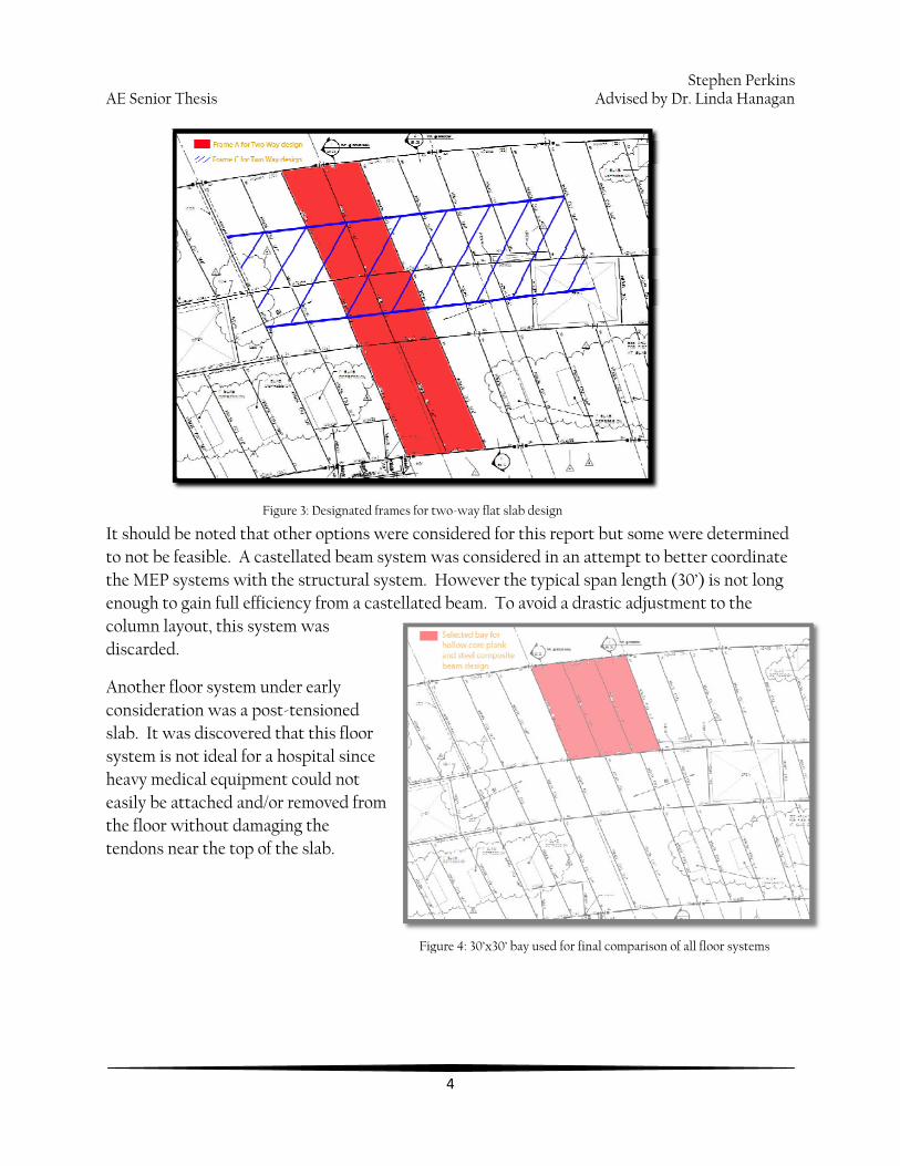
In order to effectively compare the four systems, a typical three-bay span in both directions was selected (see Figure 2 below). Since the moments in a two-way slab vary along the length of the frame, it was necessary to consider this large of an area (Figure 3 on next page). The final comparison however only considers a single 30’ x 30’ bay (Figure 4 next page).
3
Figure 2: Three-bay span in both directions
Stephen PerkinsAE Senior Thesis Advised by Dr. Linda Hanagan
4
It should be noted that other options were considered for this report but some were determined to not be feasible. A castellated beam system was considered in an attempt to better coordinate the MEP systems with the structural system. However the typical span length (30’) is not long enough to gain full efficiency from a castellated beam. To avoid a drastic adjustment to the column layout, this system was discarded.
Another floor system under early consideration was a post-tensioned slab. It was discovered that this floor system is not ideal for a hospital since heavy medical equipment could not easily be attached and/or removed fthe floor without damaging the tendons near the top of the slab.
rom
Figure 3: Designated frames for two-way flat slab design
Figure 4: 30’x30’ bay used for final comparison of all floor systems

Stephen PerkinsAE Senior Thesis Advised by Dr. Linda Hanagan
5
Structural System Overview
The structural system of the New Hospital at the University Medical Center was designed by O’Donnell & Naccarato Structural Engineers using a Load Resistance Factor Design approach. It is a structural steel building with a composite floor diaphragm. Braced frames run in both directions and there are two long moment frames spanning the entire length of the building on both the south and north facades. Both the braced and moment frames are the building’s main resistance to lateral load. Due to the great length of the building in the west-east direction, an expansion joint was placed at a distance from the western façade roughly equal to 2/3 of the total building length. This effectively splits the building into two different structures which behave on their own.
Foundation
Concrete piers with sizes anywhere from 18” x 18” to 48” x 78” are attached to the base of the steel columns and transmit vertical load from the superstructure to the concrete spread footings. The size of these footings varies from as small as 3’-0” x 3’-0” x 14” to as large as 21’ x 21’ x 50”.
All footings supporting braced frame columns have mini-piles attached at their base in order to help with the high tension forces resulting from lateral loading. These piles extend to decomposed bedrock (8’-30’ deep) and provide a tensile capacity of up to 150 kips. The top of all exterior footings are at a minimum depth of 42” below grade.
The floor at the base level is concrete slab-on-grade with thicknesses from 4”-12”.
Huge concrete retaining walls with footings up to 17’-0” wide trace the perimeter of the foundation system.
Superstructure
The structural steel provides both gravity and lateral load resistance for the building. Columns are typically W14 while beams and girders range from W12-W27 shapes. Rectangular HSS shapes are used for the diagonal members in the braced frames and round HSS columns support the massive glass façade on the south face of the hospital. The HSS columns are intentionally exposed for architectural purposes. The floor layout is uniform and has a typical bay size of 30’ x 30’.
The floor system spanning over the main area of the building is composite construction. Typically, the concrete slab is 3-1/4” lightweight concrete poured over a 3” composite metal deck. In certain mechanical and roof areas, the floor system switches to a 6-1/2” normal weight concrete due to higher loads in those areas.

Stephen PerkinsAE Senior Thesis Advised by Dr. Linda Hanagan
6
The composite floor is considered to act as a rigid diaphragm and therefore able to transmit lateral forces from the façade to the braced frames. There are six braced frames in the N-S direction for each wing of the hospital. In the W-E direction, there are four braced frames and two long moment frames on the north and south sides of the building. All of these frames contribute to the lateral force resisting system.
Lateral System
The primary components of the lateral force resisting system in the New Hospital are braced and moment frames. Expansion joints are located between the D&T building and the New Hospital and within the New Hospital itself at about 2/3 the length of the building from the west façade.
On the western wing of the facility, there are six braced frames running in the N-S direction. In the W-E direction, there are four braced frames and two long moment frames. The eastern wing has a similar layout with six braced frames in the N-S and four in the W-E as well as two moment frames in the W-E.

Stephen PerkinsAE Senior Thesis Advised by Dr. Linda Hanagan
7
Materials
All of the major structural materials incorporated into the design of the New Hospital at the University Medical Center are listed in Figure 5 below. The corresponding material strengths are to the right of each item.
Concrete Footings f’c = 3000 psi Retaining walls f’c = 3000 psi Foundation walls f’c = 3000 psi Piers Min. of f’c = 3000 psi Slab on grade f’c = 3500 psi Slab on metal deck f’c = 4000 psi Lightweight concrete f’c = 3500 psi
Structural Steel Wide Flange Shapes ASTM A992 Rectangular/Square HSS Shapes ASTM A500 Grade B Steel Pipe Sections ASTM A501 or ASTM A53, Type E or S, Grade B Angles ASTM A36 Plates ASTM A36 ¾” Bolts A325 or A490 Anchor Rods ASTM F1554 Grade 55 Welding Electrode E70XX
Reinforcement Reinforcing bars ASTM A615 Grade 60 Welded Wire Fabric ASTM A185
Decking Roof deck 1-1/2” Galvanized Type B Metal Deck, 22 Ga. Floor deck 3” LOK-Floor Composite Metal Deck, 20 or 18 Ga. ¾” Shear Studs ASTM A108
Masonry Solid Units ASTM C90, f’c = 1900 psi Hollow Units ASTM C90, f’c = 1900 psi Ivany Units f’c = 3000 psi Grout f’c = 3000 psi Brick ASTM C216 Grade SW, f’c = 3000 psi
Figure 5: Structural materials used and design strengths
Stephen PerkinsAE Senior Thesis Advised by Dr. Linda Hanagan
8
Design Loads
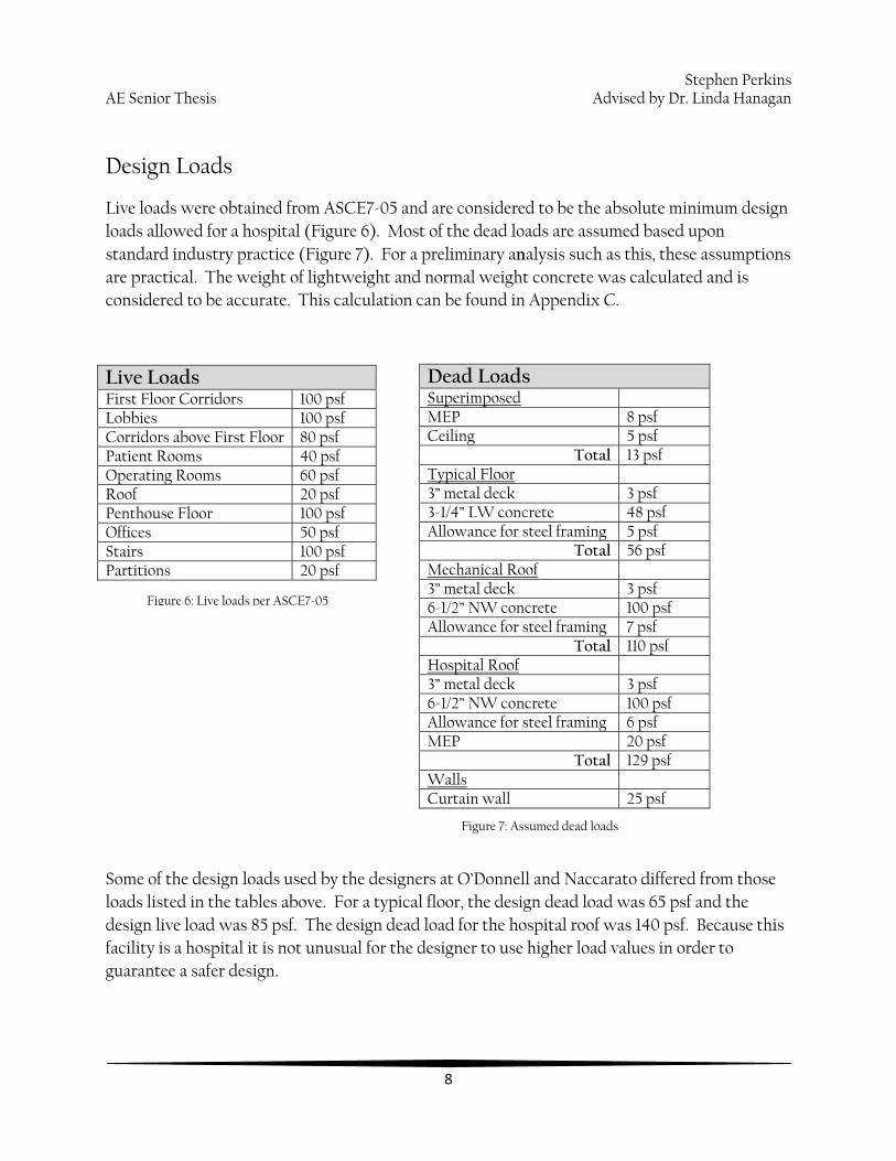
Live loads were obtained from ASCE7-05 and are considered to be the absolute minimum design loads allowed for a hospital (Figure 6). Most of the dead loads are assumed based upon standard industry practice (Figure 7). For a preliminary analysis such as this, these assumptions are practical. The weight of lightweight and normal weight concrete was calculated and is considered to be accurate. This calculation can be found in Appendix C.
Some of the design loads used by the designers at O’Donnell and Naccarato differed from those loads listed in the tables above. For a typical floor, the design dead load was 65 psf and the design live load was 85 psf. The design dead load for the hospital roof was 140 psf. Because this facility is a hospital it is not unusual for the designer to use higher load values in order to guarantee a safer design.
Dead Loads Superimposed MEP 8 psf Ceiling 5 psf
Total 13 psf Typical Floor 3” metal deck 3 psf 3-1/4” LW concrete 48 psf Allowance for steel framing 5 psf
Total 56 psf Mechanical Roof 3” metal deck 3 psf 6-1/2” NW concrete 100 psf Allowance for steel framing 7 psf
Total 110 psf Hospital Roof 3” metal deck 3 psf 6-1/2” NW concrete 100 psf Allowance for steel framing 6 psf MEP 20 psf
Total 129 psf Walls Curtain wall 25 psf
Live Loads First Floor Corridors 100 psf Lobbies 100 psf Corridors above First Floor 80 psf Patient Rooms 40 psf Operating Rooms 60 psf Roof 20 psf Penthouse Floor 100 psf Offices 50 psf Stairs 100 psf Partitions 20 psf
Figure 6: Live loads per ASCE7-05
Figure 7: Assumed dead loads

Stephen PerkinsAE Senior Thesis Advised by Dr. Linda Hanagan
9
Design Considerations
In order to have a complete investigation of the floor systems considered in this report, a set of criterion was established and grouped into appropriate categories.
Structural Architectural Construction Serviceability Weight Depth Constructability Deflection Lateral system impacts Floor plan adjustments Cost Vibration Foundation impacts Fire protection
The layout chosen for the floor system design is a three-bay span located on the north end of the New Hospital. This area of the floor plan is mainly patient rooms so a live load of 40 psf was used along with the universal superimposed dead load of 33 psf*.
Due to the sensitivity of patients, surgeons, and medical equipment, vibration is a significant factor in the design of floor systems for hospitals. Floor vibration affects human beings occupying the space as well as machinery. Therefore, AISC Design Guide 11 has two separate requirements for an operating room. The first requirement states that acceptable vibration for human comfort in an operating room is to be no greater than 0.25% of gravity. The second requirement originally set the maximum vibrational velocity for operating rooms at 8,000 μin/s. This standard was recently changed to 4,000 μin/s.
The design of every floor system considered in this report is governed by these vibration requirements. It is important to note that while the bays being designed are patient rooms and not operating rooms, this design standard was used in order to provide versatility within the floor plan. If the owner ever wanted to re-order the floor layout or add more operating rooms, this design standard would make that possible.
*Note: It is now acknowledged that partition weight should be included with the live load. The slab designs were already completed before this discovery and therefore the slab loading is slightly unconservative. (1.2*33+1.6*40=103.6k as opposed to 1.2*13+1.6*53=100.4k)
Stephen PerkinsAE Senior Thesis Advised by Dr. Linda Hanagan
10
Floor System Designs
Composite Steel Beam
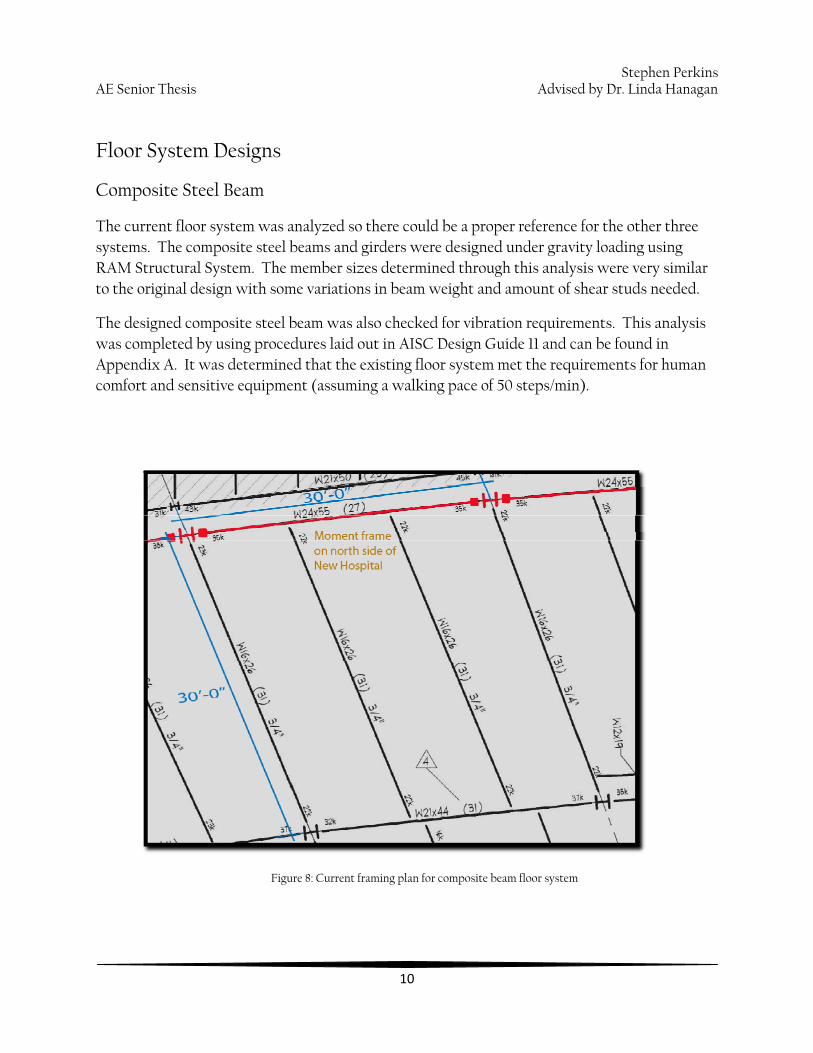
The current floor system was analyzed so there could be a proper reference for the other three systems. The composite steel beams and girders were designed under gravity loading using RAM Structural System. The member sizes determined through this analysis were very similar to the original design with some variations in beam weight and amount of shear studs needed.
The designed composite steel beam was also checked for vibration requirements. This analysis was completed by using procedures laid out in AISC Design Guide 11 and can be found in Appendix A. It was determined that the existing floor system met the requirements for human comfort and sensitive equipment (assuming a walking pace of 50 steps/min).
Figure 8: Current framing plan for composite beam floor system

Stephen PerkinsAE Senior Thesis Advised by Dr. Linda Hanagan
11
Figure 9: Composite beam and composite girder designs from RAM Structural System

Stephen PerkinsAE Senior Thesis Advised by Dr. Linda Hanagan
12
Precast Hollow Core Plank
The first alternative considered is a precast hollow core plank floor system. This system was selected because it is capable of effectively spanning 30’-0” which is the typical span length for this floor layout and it can be placed on a steel frame which provides an alternative to the composite steel beam without having to change the entire structural system of the building.
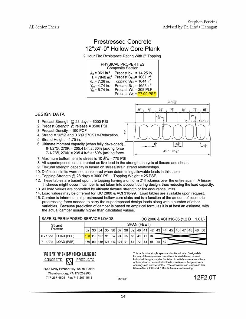
Design of the hollow core plank for bending was determined to be 12” x 4’-0” with a 2” topping using product specifications from Nitterhouse Concrete Products Inc., a well-known precast concrete producer. For the vibration check, the planks were assumed to have pinned connections at the girder supports. While this plank design met the criteria for sensitive equipment, it fell short of meeting the vibration requirement for human comfort. The 12” plank will still be considered but it will not be a good system for vibration control. The vibration calculation can be found in Appendix B.
The steel girders supporting the planks were designed using RAM Structural System. The results of the design are listed in Figure 10 below.

Stephen PerkinsAE Senior Thesis Advised by Dr. Linda Hanagan
13
The steel girders are 27” and 21” deep in their respective 30’ and 18’ spans. This already will be a problem for the hollow core plank system considering the plank thickness is already 12”. In order for this system to be effective, the column layout will have to be squeezed tighter.
On the next page is the design chart from Nitterhouse. Highlighted in yellow is the weight of the precast member and the maximum allowable load for a 32’ span. Since these hollow core planks are 4’-0” wide, all of the floor systems will be evaluated as 4’-0” strips instead of the standard unit strip.
Direction of Hollow Core Planks
Figure 11: Design of steel girders for hollow core plank system
Stephen PerkinsAE Senior Thesis Advised by Dr. Linda Hanagan
14

Stephen PerkinsAE Senior Thesis Advised by Dr. Linda Hanagan
15
Two Way Flat Slab
The thickness of the two way flat slab was determined by vibration requirements. In order to determine the natural frequency of the slab, the deflection of the slab under load needs to be approximated.
To begin, an assumption is made stating that the slab is pinned on all four sides (which it is not
but that will be adjusted later). The total deflection is equal to ∆cx + ∆my where ∆cx is the
deflection of the slab along the column strip and ∆my is the deflection of the slab in the middle
of the bay. Typical transverse distribution of moments in a slab will send 90% of the moment to the column strip and 10% to the middle strip.
The next step will be to assume that ∆cx deflects 90% of what it would deflect as a simply
supported beam and ∆my deflects 10% of what it would normally deflect as a simply supported
beam. Since ∆my sees moment from both sides of the slab, that value increases to 20%. Once
the “artificial” deflections are calculated, they are summed together and then multiplied by 0.40. This assumes that the slab is actually 80% rigid. This of course depends on the size of the columns but for now the assumption is made.
The final ∆t is used to determine the natural frequency and eventually the necessary thickness
needed to meet the vibration guidelines. It is certainly a rough approximation so the values cannot be considered exact. However, it gives a general idea of where the slab thickness needs to be and allows for comparison to other floor systems.
The rest of the slab is designed by hand. These calculations can be viewed in Appendix C.
Figure 12: Graphic for deflection of two way flat slab
Stephen PerkinsAE Senior Thesis
16
Advised by Dr. Linda Hanagan
One Way Slab with Beams
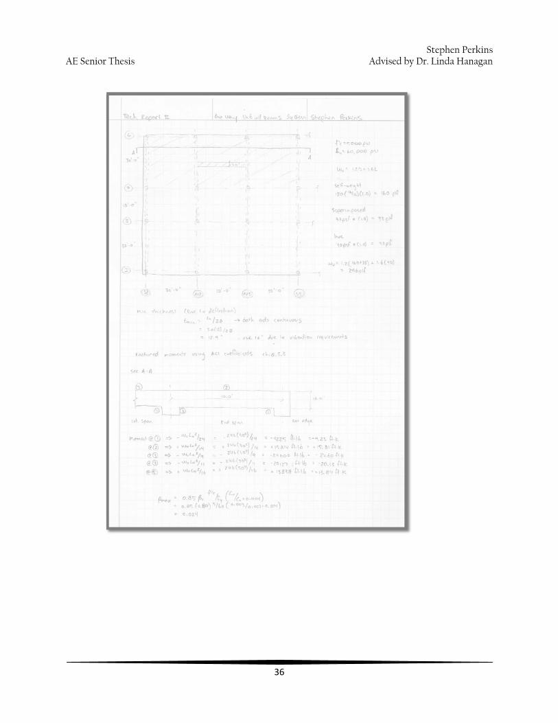
The deflection value for a one-way slab is assumed to be 60% of the deflection for a simply supported beam. This estimation was arrived at by evaluating the mid-span moments of a simply supported beam and a one-way slab with integral beams. The moment in the middle of a simply supported span (wL^2/8) is roughly 40% higher than the moment in the middle of a one-way slab with integral beams (wL^2/14). If the moment decreases by this amount, it is assumed that the deflection will also decrease by roughly the same amount in order to get a “ballpark” figure. Working under this assumption, the natural frequency of the slab can be determined which will lead to a minimum thickness required to meet vibration criterion. This thickness was determined to be 16”. This complete calculation can be found in Appendix D.
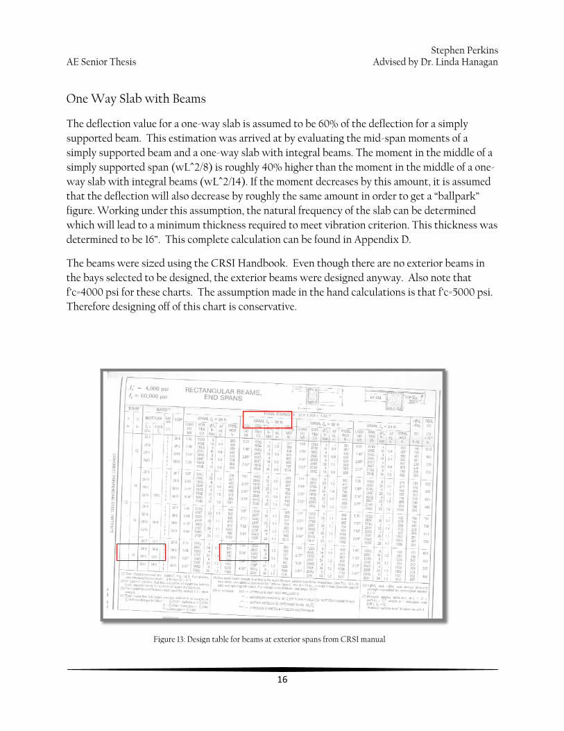
The beams were sized using the CRSI Handbook. Even though there are no exterior beams in the bays selected to be designed, the exterior beams were designed anyway. Also note that f’c=4000 psi for these charts. The assumption made in the hand calculations is that f’c=5000 psi. Therefore designing off of this chart is conservative.
Figure 13: Design table for beams at exterior spans from CRSI manual

Stephen PerkinsAE Senior Thes
17
is Advised by Dr. Linda Hanagan
Figure 14: Design table for beams at interior spans from CRSI Manual.

Stephen PerkinsAE Senior Thesis Advised by Dr. Linda Hanagan
18
Floor System Comparisons
Structural Criterion
The floor system significantly impacts the lateral force resisting system (LFRS) of a building. Since the hollow core plank system can work with a structural steel frame, the LFRS does not have to be re-configured for this system. The planks will be effective in transmitting lateral forces from the façade to the braced frames and the 2” topping will provide extra stiffness to the diaphragm. Longitudinal joints between planks can be utilized to transfer shear forces from one plank to the other.
The two-way and one-way systems will require a significant change to the LFRS of the hospital. Since the framing material is changing from steel to concrete, the steel braced frames will have to be removed. The one-way floor system has beams running in the N-S direction so there is still an option to have moment frames in that direction of the building, especially with the inherent moment connection at the beam-column intersections. It is likely that concrete shear walls will have to be designed for the two-way flat slab system since there are no beams. Shear walls will also be needed for the one-way system in the W-E direction.
Even though the concrete floor systems have a major impact on the current lateral design, they are heavier systems which make the building stiffer and able to resist wind forces more easily.
On the other hand, a heavier system will require a larger foundation. The existing spread footings are already rather large so switching to a concrete floor system might require a mat foundation in order to handle the extra building weight.
Seismic considerations must also be considered. From Tech Report I, it was determined that wind load controls the lateral design. However if the steel frame is switched out for a concrete frame, the seismic loading will increase significantly and might even lead to seismic forces controlling over wind forces.
One distinct advantage the concrete systems have over the steel systems is fire protection. Composite beam and hollow core plank floor systems will require applied fireproofing in order to obtain the necessary two hour rating where the concrete systems naturally meet that requirement.
Stephen PerkinsAE Senior Thesis Advised by Dr. Linda Hanagan
19
Architectural Criterion
The width of the designed hollow core plank is 4’-0” which does not match with the typical 30’ span of the current floor layout. For ease of construction and pre-fabrication of the precast planks the current bays will likely need to be reduced to 28’ x 28’ or increased to 32’ x 32’ so that the 4’ plank fits evenly. This could shuffle the floor plan of the hospital a little but shouldn’t have a tremendous impact.
The assumed column size for the concrete floor systems is 18” x 18” which is slightly larger than the 14” steel columns currently designed. These columns might protrude out of the interior walls forcing slight modifications to particular areas of the floor plan.
Another significant architectural consideration is the depth of each floor system. The depth of the existing composite beam system is typically just over 22”. The one-way slab will require the same depth so that will have no impact on the overall height of the building. The hollow core plank actually increases the floor system depth by nearly 20”. This alone practically eliminates it as a viable floor system for this building. The only way to significantly reduce the depth would be to tighten the column spacing which would create numerous architectural problems. The two-way flat slab is the only option which reduces the overall depth. It is 12” deep in the middle of the slab and 15” deep around the columns. The additional 10” per floor would result in a total decrease in building height of 5’.
Construction Criterion
The easiest floor systems to build are the composite beam and hollow core plank. With composite beam, the metal decking acts as the formwork for the concrete and there is no shoring required once the steel is erected. The hollow core plank is cast off-site and is ready to be installed when it arrives. Both concrete systems will require formwork and concrete placement which is labor intensive and much slower. The advantage for concrete is the shorter lead time as compared to steel.
Constructability doesn’t necessarily equate to lower costs. The least expensive floor system of the four is the two-way flat slab at nearly $12/SF. The composite beam is not much more at $12.40/SF. The one-way slab and hollow core plank are the most expensive at around $15/SF. These calculations can be viewed in Appendix G.
Stephen PerkinsAE Senior Thesis Advised by Dr. Linda Hanagan
20
Serviceability Criterion
As mentioned earlier, floor vibrations controlled the design of every system considered in this report. While all systems met the requirement for sensitive equipment at 50 steps/min, only the composite beam system met the requirement for human comfort. Since vibration is not a strength issue, it is up to the designer and owner to determine how much vibration is acceptable. The bays designed were not supporting operating rooms so these requirements are not exactly applicable. However if the owner did want to rearrange the floor layout of the hospital it is a good idea to design a significant portion of the floor system to handle vibration to the same standard as an operating room.
Due to the focus on handling the vibration issue, all of the floor systems should have no issues with deflection.
Below is a matrix which lists the evaluation for each system under every criterion.
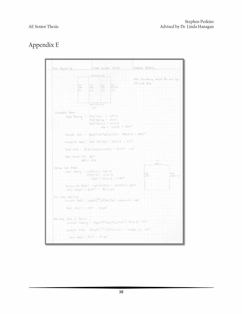
The weight determination for each system can be found in Appendix E.

Stephen PerkinsAE Senior Thesis Advised by Dr. Linda Hanagan
21
Design Comparison
Floor System: Composite
Beam Hollow Core
Plank Two-way flat
slab One-way slab with beams
Lateral Impacts n/a
Keep braced frames.
Extra stiffness due to 2” topping.
Shear walls needed.
Overall building stiffness. Increased
seismic loads.
Shear walls with possible
moment frames. Overall building
stiffness. Increased
seismic loads. Weight 42.2 psf 80.13 psf 120 psf 171 psf
Foundation Impacts
n/a
Increase spread footing size. Possible mat foundation.
Increase spread footing size. Possible mat foundation.
Increase spread footing size. Possible mat foundation.
Fire Protection Fireproof to
achieve 2 hour rating.
Fireproof to achieve 2 hour
rating. No fireproofing. No fireproofing.
Depth 6.25” 12” + 2” topping 12” 16” Total Depth 22.25” 41” 12-15” 22”
Floor Plan Impact
n/a
Would require significant
column adjustment to reduce depth.
Slightly larger columns might
affect floor plan.
Slightly larger columns might
affect floor plan.
Constructability Easiest Easier Longer, more labor intensive
Longer, more labor intensive
Cost $12.40/SF $15.18/SF $11.96/SF $14.59/SF
Vibration Meets all requirements.
Meets sensitive equip. @ 50 steps/min.
Meets sensitive equip. @ 75 steps/min
Meets sensitive equip. @ 50 steps/min
Deflection No issue No issue No issue No issue
Viable Alternative?
Existing No Too much floor plan adjustment. More expensive and heavier than composite beam.
Yes Decreased floor thickness without much floor plan impact. Inexpensive and good for vibration.
No Loses to two-way slab in nearly every category. Much heavier than composite but with same depth.
Figure 15: Design comparison matrix

Stephen PerkinsAE Senior Thesis Advised by Dr. Linda Hanagan
22
Summary
Upon completion of the alternate floor system study, it appears that the existing composite beam system is the best floor system for the New Hospital at the University Medical Center at Princeton. While it is 22” deep at typical locations, it is clearly the lightest system of the four considered. This has a significant impact when it comes to foundation size and seismic loading. There is extra importance placed upon weight in this case simply because the spread footings are rather large already. Moving to a heavier floor system will likely cause an entire re-design of the building’s foundation.
The two-way flat slab still remains a viable option to replace the composite beam. It is 10” shallower than the composite beam and less expensive, but by only a small amount. Due to deflections being lesser in two-way slabs than one-way, it can handle floor vibrations much better than the other alternatives. While it is substantially heavier than the composite system, that weight can provide more stiffness to the building as a whole which will improve its lateral resistance. Of course, the foundation issue still exists with this system as well as a complete overhaul of the lateral force resisting system. After these adjustments have been made, it is likely to cost far much more than it does right now. For now, it still remains as a possible choice.
The precast hollow core plank system will not work for this building mainly due to initial layout of the columns and bays. Planks are better in rectangular bays where they do not have to span as long a distance. While it is easy to construct and wouldn’t change the lateral system, the architectural ramifications of smaller bays or taller floor-to-floor spans is too much when there are better options already considered.
The one-way slab with beams was chosen for this study because it was thought to be better for point loading and might have an advantage with inherent moment connections at the beam-column intersections. These benefits do not outweigh the costs of a much heavier system that is more expensive and is beaten out by its concrete counterpart, the two-way flat slab, in nearly every category.

Stephen PerkinsAE Senior Thesis Advised by Dr. Linda Hanagan
23
Appendix A

Stephen PerkinsAE Senior Thesis Advised by Dr. Linda Hanagan
24

Stephen PerkinsAE Senior Thesis Advised by Dr. Linda Hanagan
25

Stephen PerkinsAE Senior Thes d by Dr. Linda Hanagan
26
is Advise
Appendix B

Stephen PerkinsAE Senior Thesis Advised by Dr. Linda Hanagan
27

Stephen PerkinsAE Senior Thesis Advised by Dr. Linda Hanagan
28
Appendix C

Stephen PerkinsAE Senior Thesis Advised by Dr. Linda Hanagan
29

Stephen PerkinsAE Senior Thesis Advised by Dr. Linda Hanagan
30

Stephen PerkinsAE Senior Thesis Advised by Dr. Linda Hanagan
31

Stephen PerkinsAE Senior Thesis Advised by Dr. Linda Hanagan
32

Stephen PerkinsAE Senior Thesis Advised by Dr. Linda Hanagan
33

Stephen PerkinsAE Senior Thesis Advised by Dr. Linda Hanagan
34

Stephen PerkinsAE Senior Thesis Advised by Dr. Linda Hanagan
35
Appendix D
Stephen PerkinsAE Senior Thesis Advised by Dr. Linda Hanagan
36

Stephen PerkinsAE Senior Thesis Advised by Dr. Linda Hanagan
37
Stephen PerkinsAE Senior Thesis Advised by Dr. Linda Hanagan
38
Appendix E

Stephen PerkinsAE Senior Thesis Advised by Dr. Linda Hanagan
39
Appendix F
One Way Slab w/ Beams Vibration Analysis fo 1.25
wlive 40 psf width 4 ft f'c 5000 psi β 0.05 wdead 33 psf span 30 ft Po 65 lb Fm/W 1.3
Design-for 185 lb person walking at 50 steps/min 16 14 12 10
I 11468.8 in^4 7683.2 in^4 4838.4 in^4 2800 in^4 w 640 plf 560 plf 480 plf 400 plf
wu 932 plf 852 plf 772 plf 692 plf E 5038136 psi 5038136 psi 5038136 psi 5038136 psi
∆ 0.18 in 0.24 in 0.35 in 0.54 in fn 8.42 Hz 7.21 Hz 6.01 Hz 4.83 Hz
ap/g 0.0024 0.0041 0.0069 0.0116
∆(point) 1.01E-05 in/lb 1.51E-05 in/lb 2.39E-05 in/lb 4.13E-05 in/lb Uv 1180.6 lb/s^2 1180.6 lb/s^2 1180.6 lb/s^2 1180.6 lb/s^2
V 0.001415 in/s 0.002467 in/s 0.004700 in/s 0.010108 in/s
1415 μin/s 2467 μin/s 4700 μin/s 10108 μin/s
fo 2.5
wlive 40 psf width 4 ft f'c 5000 psi β 0.05 wdead 33 psf span 28 ft Po 65 lb Fm/W 1.5
Design-for 185 lb person walking at 75 steps/min 16 14 12 10
I 11468.8 in^4 7683.2 in^4 4838.4 in^4 2800 in^4 w 640 plf 560 plf 480 plf 400 plf
wu 932 plf 852 plf 772 plf 692 plf E 5038136 psi 5038136 psi 5038136 psi 5038136 psi
∆ 0.13 in 0.18 in 0.26 in 0.41 in fn 9.67 Hz 8.28 Hz 6.90 Hz 5.54 Hz
ap/g 0.0017 0.0030 0.0054 0.0096
∆(point) 8.21E-06 in/lb 1.22E-05 in/lb 1.95E-05 in/lb 3.36E-05 in/lb Uv 5448.7 lb/s^2 5448.7 lb/s^2 5448.7 lb/s^2 5448.7 lb/s^2
V 0.004626 in/s 0.008066 in/s 0.015363 in/s 0.033041 in/s
4626 μin/s 8066 μin/s 15363 μin/s 33041 μin/s

Stephen PerkinsAE Senior Thesis Advised by Dr. Linda Hanagan
40
Two Way Flat Slab Vibration Analysis fo 1.25
wlive 40 psf width 4 ft f'c 5000 psi β 0.05
wdead 33 psf span 30 ft Po 65 lb Fm/W 1.3
Design- for 185 lb person walking at 50 steps/min
12 11 10 9
I 6912 in^4 5324 in^4 4000 in^4 2916 in^4
w 480 plf 440 plf 400 plf 360 plf
wu 772 plf 732 plf 692 plf 652 plf
E 5038136 psi 5038136 psi 5038136 psi 5038136 psi
∆(cx) 0.36 in 0.45 in 0.56 in 0.73 in
∆(mx) 0.08 in 0.10 in 0.13 in 0.16 in
∆(total) 0.18 in 0.22 in 0.28 in 0.36 in
fn 8.39 Hz 7.56 Hz 6.74 Hz 5.93 Hz
ap/g 0.0030 0.0042 0.0059 0.0083
∆(point,cx) 2.51E-05 in/lb 3.26E-05 in/lb 4.34E-05 in/lb 5.95E-05 in/lb
∆(point,mx) 5.58E-06 in/lb 7.25E-06 in/lb 9.65E-06 in/lb 1.32E-05 in/lb
∆(point,total) 1.23E-05 in/lb 1.59E-05 in/lb 2.12E-05 in/lb 2.91E-05 in/lb
Uv 1180.6 lb/s^2 1180.6 lb/s^2 1180.6 lb/s^2 1180.6 lb/s^2
V 0.001729 in/s 0.002490 in/s 0.003718 in/s 0.005797 in/s
1729 μin/s 2490 μin/s 3718 μin/s 5797 μin/s

Stephen PerkinsAE Senior Thesis Advised by Dr. Linda Hanagan
41
Two Way Flat Slab fo 2.5 Vibration Analysis wlive 40 psf width 4 ft f'c 5000 psi β 0.05
wdead 33 psf span 28 ft Po 65 lb Fm/W 1.5 Design- for 185 lb person walking at 75 steps/min
12 11 10 9 I 6912 in^4 5324 in^4 4000 in^4 2916 in^4
w 480 plf 440 plf 400 plf 360 plf wu 772 plf 732 plf 692 plf 652 plf
E 5038136 psi 5038136 psi 5038136 psi 5038136 psi
∆(cx) 0.28 in 0.34 in 0.43 in 0.55 in
∆(mx) 0.06 in 0.08 in 0.09 in 0.12 in
∆(total) 0.13 in 0.17 in 0.21 in 0.27 in fn 9.63 Hz 8.68 Hz 7.74 Hz 6.81 Hz
ap/g 0.0021 0.0030 0.0045 0.0066
∆(point,cx) 2.04E-05 in/lb 2.65E-05 in/lb 3.53E-05 in/lb 4.84E-05 in/lb
∆(point,mx) 4.54E-06 in/lb 5.89E-06 in/lb 7.84E-06 in/lb 1.08E-05 in/lb
∆(point,total) 9.99E-06 in/lb 1.30E-05 in/lb 1.73E-05 in/lb 2.37E-05 in/lb Uv 5448.7 lb/s^2 5448.7 lb/s^2 5448.7 lb/s^2 5448.7 lb/s^2
V 0.005651 in/s 0.008139 in/s 0.012152 in/s 0.018951 in/s
5651 μin/s 8139 μin/s 12152 μin/s 18951 μin/s

Stephen PerkinsAE Senior Thesis Advised by Dr. Linda Hanagan
42
Appendix G
Cost Analysis
Composite Beam Concrete and
Placement Description Quantity Units Material Labor Equipment Total Cost
LWC 4000 psi 9.04 CY 106 15.5 5.65 127.15 $ 1,149.44
Steel Framing Description Quantity Units Material Labor Equipment Total Cost
W16 x 26 30 LF 43 2.44 1.74 47.18 $ 1,415.40 W24 x 55 30 LF 91 3.18 1.69 95.87 $ 2,876.10 W21x 44 30 LF 72.5 3.32 1.76 77.58 $ 2,327.40
Steel Decking Description Quantity Units Material Labor Equipment Total Cost
3", 20 Ga. 900 SF 2.98 0.48 0.04 3.5 $ 3,150.00
Shear Studs Description Quantity Units Material Labor Equipment Total Cost
3/4" dia 4.75" long 131 LF 0.66 0.79 0.41 1.86 $ 243.66 Grant Total $ 11,162.00
Cost per SF $ 12.40

Stephen PerkinsAE Senior Thesis Advised by Dr. Linda Hanagan
43
Hollow Core Plank 12" Plank
Description Quantity Units Material Labor Equipment Total Cost 12" thick 900 SF 8.35 0.79 0.47 9.61 $ 8,649.00
Steel Framing Description Quantity Units Material Labor Equipment Total Cost W27 x 84 30 LF 139 2.96 1.58 143.54 $ 4,306.20 W8 x 10 30 LF 16.5 4.06 2.9 23.46 $ 703.80
Grand Total $ 13,659.00
Cost per SF $ 15.18
Two Way Flat Slab Concrete and
Placement Description Quantity Units Material Labor Equipment Total Cost
LWC 5000 psi 33.33 CY 111 12.05 4.39 127.44 $ 4,247.58
Slab Formwork Description Quantity Units Material Labor Equipment Total Cost
2 use 900 SF 2.62 3.67 0 6.29 $ 5,661.00
Reinforcing Steel Description Quantity Units Material Labor Equipment Total Cost
#6 62 Each 6.4 7.45 0 13.85 $ 858.70 Grand Total $ 10,767.28
Cost per SF $ 11.96

Stephen PerkinsAE Senior Thesis Advised by Dr. Linda Hanagan
44
One Way Slab w/ Beams
Concrete and Placement
Description Quantity Units Material Labor Equipment Total Cost LWC 5000 psi 44.44 CY 111 12.05 4.39 127.44 $ 5,663.43
Beam Formwork Description Quantity Units Material Labor Equipment Total Cost
12" wide, 2 use 150 SF 2.62 3.67 0 6.29 $ 943.50
Slab Formwork Description Quantity Units Material Labor Equipment Total Cost
2 use 900 SF 2.62 3.67 0 6.29 $ 5,661.00
Reinforcing Steel Description Quantity Units Material Labor Equipment Total Cost
#6 62 Each 6.4 7.45 13.85 $ 858.70 Grand Total $ 13,126.63
Cost per SF $ 14.59