Technical Report 3 - Penn State Engineering · This is shown in Lehigh’s Campus Master Plan of...
40
TECHNICAL REPORT 3 S.T.E.P.S. Building Lehigh University Bethlehem, PA Joseph S. Murray, Structural Option Faculty Advisor: Linda Hanagan September 17 th , 2012 Lateral System Analysis
-
Upload
trinhquynh -
Category
Documents
-
view
212 -
download
0
Transcript of Technical Report 3 - Penn State Engineering · This is shown in Lehigh’s Campus Master Plan of...

Technical Report 3
Lateral System Analysis
Joseph S. Murray
S.T.E.P.S. Building Lehigh University Bethlehem, PA
0
TECHNICAL REPORT 3
S.T.E.P.S. Building
Lehigh University
Bethlehem, PA
Joseph S. Murray, Structural Option
Faculty Advisor: Linda Hanagan
September 17th, 2012
Lateral System
Analysis

Technical Report 3
Lateral System Analysis
Joseph S. Murray
S.T.E.P.S. Building Lehigh University Bethlehem, PA
1
Table of Contents
Executive Summary 3
Building Introduction 4
Structural System 6
Floor System 6
Vertical Members 10
Foundation 10
Roof System 10
Lateral System 11
Design Codes 11
Design Loads 12
Live Loads 12
Dead Loads 13
Roof Live Load 13
Roof Dead Load 13
Roof Snow Load 14
Uniform Roof Snow Load 14
Drift Snow Load 14
Penthouse Live Load 14
Penthouse Dead Load 15
Brick Façade Load 15
Glass Curtain Wall Load 15
Penthouse Wall Load 15
Wind Pressures 16
Seismic Loads 18
Seismic Design Factors 19
Effective Seismic Weight 20
Seismic Design Loads 20
RAM Model 21
Center of Mass, Center of Rigidity 23
Load Combinations 24
Maximum Story Shears 24
Overturning Moment 25
Wind Load Cases 26
Maximum Story Drifts 27
Lateral Spot Checks 30
Conclusion 34

Technical Report 3
Lateral System Analysis
Joseph S. Murray
S.T.E.P.S. Building Lehigh University Bethlehem, PA
2
A-1 Floor Plans 35
A-2 Wind Calculations 37

Technical Report 3
Lateral System Analysis
Joseph S. Murray
S.T.E.P.S. Building Lehigh University Bethlehem, PA
3
Executive Summary
The S.T.E.P.S. Building in Bethlehem, PA sits on Lehigh University’s campus. It is a mixed use facility
consisting of laboratories, lecture halls, and faculty offices. The building is divided into two main wings
which are bridged by a central atrium.
The structural system of the building consists of semi-rigid moment frames and full moment frames. It
uses a composite floor as a rigid diaphragm to transfer lateral loads imposed on the façade to the beams
and girders. The beams and girders then transfer these loads through their moment connections to a
network of mainly W14 columns. The columns finally transfer the load into the soil through a
combination of spread footings and mat foundations.
In order to better analyze the lateral force resisting structural system, a 3D model was produced in RAM
Structural System. The model was constructed from the floor plans, specifications, and detailed drawings
of the S.T.E.P.S. Building. All gravity and lateral members were appropriately sized according to the
plans. RAM was used to check the center of mass and center of rigidity of each floor which were
relatively close together. The RAM program checked for incidental torsional shear in the wind calculation
based on this eccentricity.
To simplify the design and avoid error, only lateral loads were considered. This left the load
combinations of 1.6W and 1.0E to be used in analysis. Based on the location and the seismic information
on the structural drawings, wind controlled over seismic in all cases.
Story shears were checked using RAM and the results were used to check the overturning moment
imposed on the building by the wind loads. This value was checked against the weight of the building
multiplied by the eccentricity of the center of mass. The resisting moment was greater than the
overturning moment, so uplift will not occur.
Four locations were chosen to check the wind drift limit of h/400. All of these locations passed for each
story.
Two manual lateral spot checks were performed to assess the results of the computer program by hand.
A braced frame and a moment frame were checked against the calculated drift from the RAM program.
They were also checked for strength requirements according to a specification for the bracing on the
drawings and against allowable moment in AISC 14th Edition.
Technical Report 3
Lateral System Analysis
Joseph S. Murray
S.T.E.P.S. Building Lehigh University Bethlehem, PA
4
Building Introduction
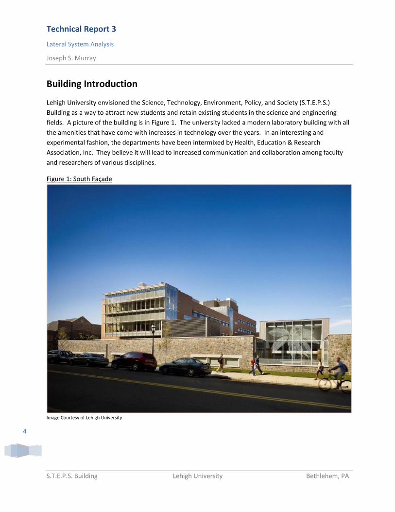
Lehigh University envisioned the Science, Technology, Environment, Policy, and Society (S.T.E.P.S.)
Building as a way to attract new students and retain existing students in the science and engineering
fields. A picture of the building is in Figure 1. The university lacked a modern laboratory building with all
the amenities that have come with increases in technology over the years. In an interesting and
experimental fashion, the departments have been intermixed by Health, Education & Research
Association, Inc. They believe it will lead to increased communication and collaboration among faculty
and researchers of various disciplines.
Figure 1: South Façade
Image Courtesy of Lehigh University

Technical Report 3
Lateral System Analysis
Joseph S. Murray
S.T.E.P.S. Building Lehigh University Bethlehem, PA
5
The building is oriented on the corner of East Packer Ave. and Vine St. as shown in Figure 2. The streets
do not intersect at a 90 degree angle. The architects decided to use site lines to orient the building,
which led to the nonlinear shape of the façade along Vine St.
Figure 2: Site Plan
Image Courtesy of BCJ Architects
Lehigh University slowly purchased the properties which were on the building site as they planned for a
building to be put there. The location was ideal for expanding campus activities close to the campus
core. This is shown in Lehigh’s Campus Master Plan of 2000 in Figure 2.

Technical Report 3
Lateral System Analysis
Joseph S. Murray
S.T.E.P.S. Building Lehigh University Bethlehem, PA
6
Figure 2: Campus Master Plan
Image Courtesy of Lehigh University
The building is also connected to an existing structure through the use of a raised pathway that is
enclosed. This further encourages interconnectivity between faculty, researchers, and students, because
the adjoining building contains part of the College of Social Sciences. Between this adjacent building and
S.T.E.P.S., there is a large open lawn. The university made a significant effort to maintain this lawn for
extracurricular activities such as frisbee, croquet, and football. The S.T.E.P.S. Building is divided into
three wings for the purpose of this analysis. These wings are diagramed in Figure 3.

Technical Report 3
Lateral System Analysis
Joseph S. Murray
S.T.E.P.S. Building Lehigh University Bethlehem, PA
7
Figure 3: Wings A, B, and C of S.T.E.P.S. Building
Image courtesy of Bing.com
Wing A is a one story structure with a lounge and entryway. It has raised clearstories to allow for natural
daylight to illuminate the space. It also has a 12” deep green roof supported by structural wood which
helped in earning LEED Certification. The building is LEED Gold certified by the United States Green
Building Council (USGBC). Because of its limited building height, Wing A will not be analyzed in this
report.
Wing B is a four story steel framed structure oriented along Packer Ave. There is a large atrium with
lounge areas connecting Wing B to Wing C on each floor. Wing C is also steel framed and is 5 stories.
The gravity and lateral load resisting elements continue uninterrupted through the atrium. As a result,
Wing B and Wing C will be treated as one building. The building’s lateral system consists of moment
connections between columns and beams throughout the building.
Sustainable features of the building include the green roof, high-efficiency glazing, sun shading, and
custom mechanical systems.

Technical Report 3
Lateral System Analysis
Joseph S. Murray
S.T.E.P.S. Building Lehigh University Bethlehem, PA
8
Structural System
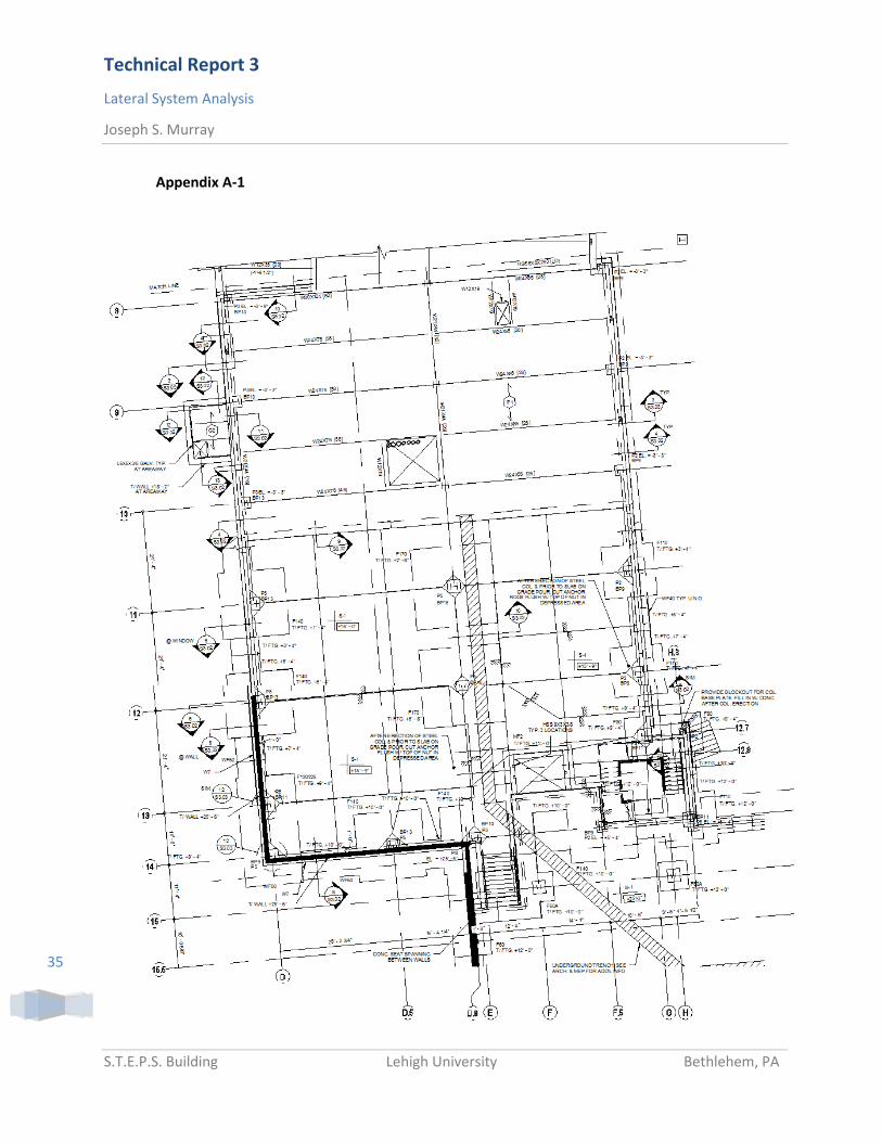
Figure 4: Typical Building Floor Plan
For a full floor plan, see Appendix A-1.
Floor System
There is a composite steel deck floor system in place for all floors in Wings B & C above grade. Basement
floors are slab on grade.
Along Vine St., which will be considered the longitudinal direction of the building, typical girders have a
center to center span of 21’-4” with one intersecting beam at their midpoint. The transverse beams
which run parallel to Packer Ave. have a span anywhere from 36’-11” to 42’8”.
The decking is a 3” deep 18 gauge steel deck with 4-1/2” normal weight concrete topping and welded
wire fabric. The bulk of the decking is run longitudinally throughout Wings B & C and has a span of 10’8”
between beam centerlines. The exceptions to this are two bays to the very south of Wing B along Packer
Ave. These bays are oriented transversely. The total thickness ends up being 7-1/2” with a 6x6” W2.9 x

Technical Report 3
Lateral System Analysis
Joseph S. Murray
S.T.E.P.S. Building Lehigh University Bethlehem, PA
9
W2.9 welded wire fabric embedded ¾” from the top of the slab. Figure 5 shows a typical detail of the
composite floor decking.
Figure 5: Composite Floor Deck Detail
The floor system is supported by wide flange beams designed as simply supported. A combination of full
moment connections, semi-rigid moment connections, and shear connections are used. Typical sizes for
transverse beams are W24x55 and W24x76. The girders are W21x44. Most beams have between 28 and
36 studs to transfer shear. Figure 5 shows a typical Full Moment Connection with field welds noted.
Figure 6 shows the entirety of the first floor system for Wing B. Figure 8 shows the entirety of the first
floor system for Wing C.
Vertical Members
Wide flange columns are used throughout the building for gravity loads. They are arranged for strong
axis bending in the transverse direction. Most spans have a column at either end with another at the
midpoint.
W14 is the most common section size with weights varying from W14x90 all the way up to W14x192 on
the lower floors.
Foundation
Schnabel Engineering performed a geotechnical analysis of the site in 2007. This concluded that the soil
had sufficient bearing capacity to support the loads from the building.
Interior columns are supported by a mat foundation 18’ wide and 3’-6” deep shown in Figure 6 and
Figure 7. Exterior columns bear on square footings ranging from 11’x11’ to 16’x16’ with depths from 1’6”
to 2’. These are tied into the foundation by base plates with concrete piers.

Technical Report 3
Lateral System Analysis
Joseph S. Murray
S.T.E.P.S. Building Lehigh University Bethlehem, PA
10
Figure 6: Mat Foundation Plan View
Figure 7: Mat Footing Schedule
The reinforced foundation walls have strip footings ranging from 2’ to 6’ wide with depths between 1’
and 2’. These are monolithically cast with the piers for the exterior columns.
Roof System
The roof decking consists of a 3” 16 gauge steel roof deck with a sloped roof for drainage. Topping
ranges from ¼” to 4-1/2” to achieve a ¼”:1’ slope. Therefore, total thickness ranges from 3-1/4” to 7-
1/2”. Framing is similar to floor framing with wide flanges ranging from W24x55 to W24x68.

Technical Report 3
Lateral System Analysis
Joseph S. Murray
S.T.E.P.S. Building Lehigh University Bethlehem, PA
11
The floor system has increased loads where the mechanical penthouses are situated. The penthouse
itself is framed with square HSS tubing. Heavier W27x84 wide flange beams support this area.
Lateral System
The building resists lateral loads by moment connections at the beam to column locations. They are
continuous throughout the building and beams are designed as simply supported for gravity loads. The
moment connections are designed only to take lateral loads. A typical full moment connection is shown
in Figure 8. Many of these moment connections are semi-rigid connections to give the system more
flexibility. An example of layout of the two types of moment connections in the floor plan is shown
below in Figure 9. The triangles are full moment connections and the dots are semi-rigid.
Figure 8: Typical Full Moment Connection

Technical Report 3
Lateral System Analysis
Joseph S. Murray
S.T.E.P.S. Building Lehigh University Bethlehem, PA
12
Figure 9:
The lateral loads seen in the Penthouse are going to be the greatest based on height. At the highest
Penthouse roof level, there are moment connections in the transverse direction and single angle braced
frames in the longitudinal direction. The connections to the roof of the building are rigidly connected to
the roof framing members. These members then transfer the load to flexible moment connections in the
columns supporting the roof. These roof members are a larger W27x102 compared to adjacent members
such as W24x68 or W27x84.
Design Codes
The primary design code used to construct the S.T.E.P.S. Building was the Pennsylvania Uniform
Construction Code (PUCC). The PUCC is the primary code adopted by the city of Bethlehem,
Pennsylvania. The PUCC is based on the International Code Council (ICC). When design was completed in
2008, the 2006 PUCC referenced the following codes:
2006 International Building Code
2006 International Electrical Code

Technical Report 3
Lateral System Analysis
Joseph S. Murray
S.T.E.P.S. Building Lehigh University Bethlehem, PA
13
2006 International Fire Code
2006 International Fuel Gas Code
2006 International Mechanical Code
ASCE 7-05, Minimum Design Loads for Buildings and Other Structures
AISC Steel Construction Manual, 13th Edition
ACI 318-05, Building Code Requirements for Structural Concrete
ACI 530-05, Building Code Requirements for Masonry Structures
The primary codes employed in analysis were the AISC Manual and ASCE 7-05
Design Loads
Live Loads
Table 1: Live Load Values
Occupancy Design Load on Drawings ASCE 7-05 Load (Tables 4-1, C4-1)
Office 50 PSF 50 PSF + 20 PSF (Partitions)
Classroom 40 PSF 40 PSF
Laboratory 100 PSF 100 PSF
Storage 125 PSF 125 PSF
Corridors/Lobbies @ Ground Level
100 PSF 100 PSF
Corridors Above Ground Level 80 PSF 80 PSF
Dead Loads
Table 2: Calculated Dead Load
Dimension Unit Weight Load (PSF)
3” 18 Ga. Composite Deck
2.84
4-1/2” Topping 75
Self-Weight 5
MEP Allowance 10
Ceiling Allowance 5
TOTAL 97.84 PSF

Technical Report 3
Lateral System Analysis
Joseph S. Murray
S.T.E.P.S. Building Lehigh University Bethlehem, PA
14
Roof Live Load
Table 3: Roof Live Load
Occupancy Design Load on Drawings
ASCE 7-05 Load (Tables 4-1, C4-1)
Design Load
Roof N/A 20 PSF 20 SF
Roof Dead Load
Table 4: Roof Dead Load
Dimension Unit Weight Load (PSF)
3” 16 Ga. NS Roof Deck 2.46
3” Concrete Topping (Avg.)
0.290 CF/SF 150 43.5
Self-Weight 5
Roofing Allowance 10
TOTAL 60.96 SF
Roof Snow Load
Uniform Roof Snow Load
Table 5: Uniform Roof Snow Load
Design Factor ASCE 7-05 Design Value
Snow Load (Pq) Figure 7-1 30 PSF
Roof Exposure Table 7-2 Fully Exposed
Exposure Type Section 6.5.6.2 B
Exposure Factor (Ce) Table 7-2 .9
Thermal Factor (Ct) Table 7-3 1.0
Building Type Table 1-1 III
Importance Factor (I) Table 7-4 1.1
Flat Roof Snow Load (Pf) Equation 7-1 20.8 PSF
Minimum Snow Load (Pf,min) Section 7.2 22 PSF
Design Snow Load Section 7.2 22 PSF
Pf = 0.7(Ce)(Ct)(I)(Pq)
Pf = 0.7(.9)(1.0)(1.1)(30) = 20.8 PSF

Technical Report 3
Lateral System Analysis
Joseph S. Murray
S.T.E.P.S. Building Lehigh University Bethlehem, PA
15
20.8 < Pf,min = 22 Use 22 PSF as the Design Snow Load
5.5.2 Drift Snow Load
NOTE: For simplification of this analysis, snow drift was not considered. However, because of the raised
penthouses, it will be necessary to consider snow drift later.
Penthouse Live Load
Table 6: Penthouse Live Load
Occupancy Design Load on Drawings
ASCE 7-05 Load (Tables 4-1, C4-1)
Design Load
Mechanical Room N/A 200 PSF 200 PSF
Penthouse Dead Load
Table 7: Penthouse Dead Load
Dimension Unit Weight Design Load (PSF)
3” 18 Ga. Composite Deck
2.84
4-1/2” Concrete Topping
75
Self-weight 5
MEP Allowance 10
Ceiling Allowance 5
TOTAL 97.84 PSF

Technical Report 3
Lateral System Analysis
Joseph S. Murray
S.T.E.P.S. Building Lehigh University Bethlehem, PA
16
Brick Façade Load
Table 8: Brick Façade Load (Per Level)
Height Unit Weight (PSF) Design Load (PLF)
Brick Veneer 10’-3” 40 410
2” Rigid Insulation 10’-3” 1.5 15.375
Cold Formed Steel Framing
10’-3” 1 10.25
Gypsum Wall Board (5/8”)
10’-3” 2.5 25.625
Window (Glass, Frame, Sash) (ASCE 7-05 Table C3-1)
5’-1” 8 40.8
TOTAL 502.1 PLF
Glass Curtain Wall Load
Table 9: Glass Curtain Wall Load (Per Level)
Dimension Unit Weight (PSF) Design Load (PLF)
Window (Glass, Frame, Sash) (ASCE 7-05 Table C3-1)
15’-4” 8 122.4 PLF
Penthouse Wall Load
Table 10: Penthouse Wall Load
Dimension Unit Weight (PSF) Load (PLF)
Metal Wall Panel 16’-4” 5 81.7
Steel Framing 16’-4” 2 32.7
Bracing Allowance 16’-4” 3 49
TOTAL 163.4 PLF

Technical Report 3
Lateral System Analysis
Joseph S. Murray
S.T.E.P.S. Building Lehigh University Bethlehem, PA
17
Wind Pressures
ASCE 7-05 was used for wind design. The Analytical Procedure in Chapter 6 is specifically what was
instituted.
Table 11: Wind Design Factors:
Design Factor ASCE 7-05 E/W Value N/S Value
Design Wind Speed (V)
Figure 6-1C 90 mph 90 mph
Building Type Table 1-1 III III
Importance Factor (I) Table 6-1 1.15 1.15
Exposure Type 6.5.6.2 Type B Type B
Average Height (z) 6.5.8 84’ 100’
Table 12: Design Wind Pressure by Level (Transverse Direction)
Level Height kz qz Pz (PSF) (Windward)
Ph (PSF) (Leeward)
Ptotal (PSF)
1 0’-0” 0.57 11.55 14.21 -18.18 25.47
2 15’-4” 0.58 11.76 14.46 -18.18 25.93
3 30’-8” 0.71 14.39 17.7 -18.18 31.73
4 46’-0” 0.79 16.01 19.69 -18.18 35.3
Roof/5th 60’-8” 0.85 17.22 21.18 -18.18 37.97
Roof/Penthouse 77’-0” 0.92 18.65 22.94 -18.18 41.12
Table 13: Design Wind Pressure by Level (Longitudinal Direction)
Level Height kz qz Pz (PSF) (Windward)
Ph (PSF) (Leeward)
Ptotal (PSF)
G 0’-0” 0.57 11.55 14.21 N/A 14.21
1 15’-4” 0.58 11.76 14.46 -14.67 23.33
2 30’-0” 0.70 14.4 17.70 -14.67 28.55
3 45’-4” 0.79 16.01 19.69 -14.67 31.76
4 61’-0” 0.85 17.23 21.19 -14.67 34.18
Roof/5th 77’-4” 0.92 18.65 22.94 -14.67 37.00
Roof/Penthouse 92’-0” 0.96 19.46 23.94 -14.67 38.61

Technical Report 3
Lateral System Analysis
Joseph S. Murray
S.T.E.P.S. Building Lehigh University Bethlehem, PA
18
Seismic Loads
Chapters 11 and 12 of ASCE 7-05 were used for seismic load design. The Equivalent Lateral Force
procedure tests whether the building has the capability of handling a seismic event based on site and
building properties.
Hand calculations can be found in Appendix A-2.
Seismic Design Factors
Design factors were the same for transverse and longitudinal directions since the building’s lateral
framing system consists of moment frames in both directions. Instead of determining the actual
fundamental frequency through extensive calculation, the approximate fundamental period was
determined using ASCE 7-05 Section 12.8.2.1.
Table 14: Seismic Load Design Factors
Design Factor ASCE 7-05 Value
Short Period Spectral Response Acceleration (Ss)
USGS 0.291
One Second Spectral Response Acceleration (S1)
USGS 0.081
Site Class Table 11.4-1 C
Short Period Site Coefficient (Fa)
Table 11.4-2 1.2
Long Period Site Coefficient (Fv)
Equation 11.4-1 1.7
Adjusted MCE Short Period Spectral Response Acceleration (Sms)
Equation 11.4-1 0.349
Adjusted MCE One Second Spectral Response Acceleration (SM1)
Equation 11.4-2 0.138
Design Short Period Spectral Response Acceleration (SMs)
Equation 11.4-3 0.233
Design One Second Spectral Response Acceleration (SM1)
Equation 11.4-4 0.0918
Maximum Height from Base (hn)
N/A 108.3’
Approximate Period Parameter (Ct)
Table 12.8-2 0.028
Approximate Period Parameter (x)
Table 12.8-2 0.8

Technical Report 3
Lateral System Analysis
Joseph S. Murray
S.T.E.P.S. Building Lehigh University Bethlehem, PA
19
Approximate Fundamental Period (Ta)
Equation 12.8-7 1.19 Hz
Building Type Table 1-1 III
Importance Factor (I) Table 11.5-1 1.25
Seismic Design Category Table 6-2 B
Response Modification Coefficient (R)
Table 12.2-1 3.0
System Over-strength Factor (Omega)
Table 12.2-1 3.0
Deflection Amplification Factor (Cd)
Table 12.2-1 3.0
Flexible Diaphragm Condition Section 12.3.1 Rigid
Long Period Translation Period (TL)
Figure 22-15 6
Seismic Response Coefficient (Cs)
Equation 12.8-3 0.0321
Effective Seismic Weight
Table 15: Effective Seismic Weight by Level
Level Floor Area (SF) (96 PSF)
Roof Area (SF) (62.5 PSF)
Penthouse Floor Area (SF) (296 PSF)
Brick Façade (ft.) (510.6 PLF)
Glass Curtain Wall (ft.) (122.4 PLF)
Penthouse Wall (ft.) (246 PLF)
Effective Seismic Weight (k)
Penthouse 4497 281.06
Roof/Penthouse
7894 4497 288.7 1895.5
5 10832 9375 1557 421.3 161.3 2341.47
4 21814 589.7 89.5 2406.2
3 21814 589.7 89.5 2406.2
2 21814 589.7 89.5 2406.2
1 21814 589.7 89.5 2406.2
TOTAL 98088 21766 6054 2780.1 358 450 14143

Technical Report 3
Lateral System Analysis
Joseph S. Murray
S.T.E.P.S. Building Lehigh University Bethlehem, PA
20
Design Seismic Loads
Table 16: Seismic Design Loads by Level
Level Effective Seismic Weight (wx)
Height from Base (hx)
(wxhx)k Vertical Distribution Factor (Cvx)
Lateral Seismic Force (Fx) (k)
Seismic Design Story Shear (Vx) (k)
Overturning Moment (k-ft.)
Penthouse 281.06 k 108.3’ 3298348 0.0654 29.97 29.97 3217.11
Roof/Penthouse 1895.5 k 93’ 16390547 0.3250 147.57 177.54 13724.53
5 2341.47 k
76.7’ 13763837 0.2729 123.92 301.46 9501.36
4 2406.2 k 61.3’ 9050606 0.1794 81.48 382.94 4997.72
3 2406.2 k 46’ 5091519 0.1009 45.84 428.78 2108.76
2 2406.2 k 30.7’ 2263389 0.0448 20.37 449.15 625.02
1 2406.2 k 15.3’ 565478 0.0112 5.09 454 78.05
TOTAL 14143 k 50423724
1.0 34252.54
Seismic Base Shear = 454 k
Overturning Moment = 34252.5 k-ft.
Calculations for the earthquake analysis can be made available upon request.

Technical Report 3
Lateral System Analysis
Joseph S. Murray
S.T.E.P.S. Building Lehigh University Bethlehem, PA
21
RAM Model
RAM Structural System was used to create a 3D model of the S.T.E.P.S. Building. Gridlines were produced
from AutoCAD drawings, and line elements were used to build the framework for the lateral and gravity
force resisting systems. Steel sections and member properties were added to the line elements as noted
on the structural drawings. Any beams that had a moment connection were modeled as part of the
lateral system along with 4 braces in the penthouse frames. The majority of the beams are W-flange
members with HSS rectangular tubing used in some locations. The bracing utilized as part of the
penthouse’s lateral resisting system are L4x4x3/8 X-Bracing. Any columns which received a lateral beam
were also modeled as part of the lateral system. The columns consist mainly of W14 sections with HSS
rectangular tubing used for the elevator core and the penthouse columns. Some of the gravity beams
terminated in a concrete basement wall, and an 18” thick reinforced concrete wall was modeled as
shown on plan and in structural details. All exterior columns terminate in a spread footing foundation,
while interior columns terminated in mat foundations.
The composite floor system that exists throughout the building was modeled as a rigid diaphragm on
each floor level. Weight of steel members and the floor systems was calculated by RAM, and then the
weight of the wall system was added manually to each floor based on the floor’s perimeter and the
weight of the wall attached. Figure 12 shows the RAM model in 3D from the west direction and Figure 13
shows it from the east direction. The red color represents lateral members, and the blue color
represents gravity members. Figure 14 shows the braced frames in the penthouse in purple.
Figure 12: RAM Model (West Direction)
Figure 13: RAM Model (East Direction)

Technical Report 3
Lateral System Analysis
Joseph S. Murray
S.T.E.P.S. Building Lehigh University Bethlehem, PA
22
Figure 14: Penthouse Braced Frames

Technical Report 3
Lateral System Analysis
Joseph S. Murray
S.T.E.P.S. Building Lehigh University Bethlehem, PA
23
Center of Mass and Center of Rigidity
The center of mass (COM) and the center of rigidity (COR) were determined for each diaphragm by RAM.
After visual inspection, the locations were confirmed, and analysis of the model proceeded. Figure 15
shows the center of mass and center of rigidity for the second floor. The COM is represented by a green
circle at (38.45, 142.86), and the COR is represented by a purple circle at (40.84, 119.71).
Figure 15: Center of Mass and Center of Rigidity

Technical Report 3
Lateral System Analysis
Joseph S. Murray
S.T.E.P.S. Building Lehigh University Bethlehem, PA
24
Load Combinations:
The load combinations in ASCE 7-05 were considered in analysis. Figure 16 shows Table 2.3.2 from ASCE.
Figure 16: LRFD Load Combinations
To simplify the analysis and limit errors, only combinations with wind or seismic were initially considered.
Since the response of the lateral system is of primary concern in this analysis, gravity loads were not
considered, and the load combinations were reduced to either 1.6W or 1.0E.
Wind load cases were considered from the ASCE 7-05 Main Wind Force Resisting System method
(Method 2). These can be found in Figure 17.
After running the analysis for wind and viewing the story displacements from RAM, it was determined
that Case 1 controlled for wind in both the x and y direction of the S.T.E.P.S. Building. All other wind
cases were removed from consideration as the applied eccentricity did not produce a greater wind load.
Earthquake was checked by RAM for an Sds of 0.233 as specified by the structural drawings. Wind
controlled in both directions for every story.
Story Shears
Story shears were checked using RAM based on the controlling wind cases. The maximum story shears in
the x direction are in Figure 17, and the maximum story shears in the y direction are shown in Figure 18.

Technical Report 3
Lateral System Analysis
Joseph S. Murray
S.T.E.P.S. Building Lehigh University Bethlehem, PA
25
Figure 17: Maximum Story Shears in the X Direction
Figure 18: Maximum Story Shears in the Y Direction
Overturning Moment
The shears for each story in the x direction were multiplied by the height of each story to produce a total
overturning moment of 31,528.5 k-ft.
The resisting moment was calculated by multiplying the weight of the building by the eccentricity of the
center of mass. From previous calculations, the effective building weight is 14,143 kips. The center of
mass is 38.45 feet from the edge of the building. This results in a resisting moment of 543,798 kip-ft.
This is enough to handle the overturning moment produced by the controlling wind case

Technical Report 3
Lateral System Analysis
Joseph S. Murray
S.T.E.P.S. Building Lehigh University Bethlehem, PA
26
Figure 17: ASCE 7-05 Wind Load Cases

Technical Report 3
Lateral System Analysis
Joseph S. Murray
S.T.E.P.S. Building Lehigh University Bethlehem, PA
27
Maximum Story Drifts
RAM was used to determine the story drifts based on the controlling wind cases. Four points were
chosen as control points to establish displacement and drift data show in Figure 18 as blue dots. Tables
17-20 show the results and compare to allowable drifts of h/400 as per ASCE 7-05. Some of the frames
do not extend to levels 6 and 7 and are marked as “N/A”. The story drifts passed all acceptable drift
limits based on the RAM output and an acceptable drift of h/400.
Figure 18: Location of Control Points for Drift Analysis

Technical Report 3
Lateral System Analysis
Joseph S. Murray
S.T.E.P.S. Building Lehigh University Bethlehem, PA
28
Table 17: Maximum Lateral Displacements and Story Drifts (Column A-1)
Maximum Wind Story Drift, N-S Direction
Story Story Drift (in) Allowable Drift (in) Adequacy
Column A-1 7 N/A 3.24 OK
6 -0.3066 2.78 OK
5 0.1181 2.32 OK
4 0.1708 1.86 OK
3 0.1735 1.4 OK
2 0.1755 0.94 OK
1 0.105 0.48 OK
Maximum Wind Story Drift, E-W Direction
Story Story Drift (in) Allowable Drift (in) Adequacy
Column A-1 7 N/A 3.24 OK
6 0.1533 2.78 OK
5 0.2713 2.32 OK
4 0.4295 1.86 OK
3 0.4525 1.4 OK
2 0.4390 0.94 OK
1 0.0270 0.48 OK
Table 18: Maximum Lateral Displacements and Story Drifts (Column B-6)
Maximum Wind Story Drift, N-S Direction
Story Story Drift (in) Allowable Drift (in) Adequacy
Column B-6 7 0.3288 3.24 OK
6 -0.2756 2.78 OK
5 0.1178 2.32 OK
4 0.1705 1.86 OK
3 0.1730 1.4 OK
2 0.1744 0.94 OK
1 0.0103 0.48 OK
Maximum Wind Story Drift, E-W Direction
Story Story Drift (in) Allowable Drift (in) Adequacy
Column B-6 7 0.3551 3.24 OK
6 0.1755 2.78 OK
5 0.1929 2.32 OK
4 0.305 1.86 OK
3 0.3245 1.4 OK
2 0.2977 0.94 OK
1 0.0178 0.48 OK

Technical Report 3
Lateral System Analysis
Joseph S. Murray
S.T.E.P.S. Building Lehigh University Bethlehem, PA
29
Table 19: Maximum Lateral Displacements and Story Drifts (D.5-14)
Maximum Wind Story Drift, N-S Direction
Story Story Drift (in) Allowable Drift (in) Adequacy
Column D.5-14 7 N/A N/A N/A
6 N/A N/A N/A
5 0.1179 2.32 OK
4 0.1706 1.86 OK
3 0.1731 1.4 OK
2 0.1851 0.94 OK
1 N/A N/A N/A
Maximum Wind Story Drift, E-W Direction
Story Story Drift (in) Allowable Drift (in) Adequacy
Column D.5-14 7 N/A N/A N/A
6 N/A N/A N/A
5 0.1364 2.32 OK
4 0.2346 1.86 OK
3 0.2893 1.4 OK
2 0.2315 0.94 OK
1 N/A N/A N/A
Table 20: Maximum Lateral Displacements and Story Drifts (E.5-12)
Maximum Wind Story Drift, N-S Direction
Story Story Drift (in) Allowable Drift (in) Adequacy
Column E.5-12 7 N/A N/A N/A
6 N/A N/A N/A
5 0.1181 2.32 OK
4 0.1708 1.86 OK
3 0.1735 1.4 OK
2 0.1756 0.94 OK
1 0.0105 0.48 OK
Maximum Wind Story Drift, E-W Direction
Story Story Drift (in) Allowable Drift (in) Adequacy
Column E.5-12 7 N/A N/A N/A
6 N/A N/A N/A
5 0.1685 2.32 OK
4 0.2719 1.86 OK
3 0.2975 1.4 OK
2 0.2626 0.94 OK
1 0.0155 0.48 OK

Technical Report 3
Lateral System Analysis
Joseph S. Murray
S.T.E.P.S. Building Lehigh University Bethlehem, PA
30
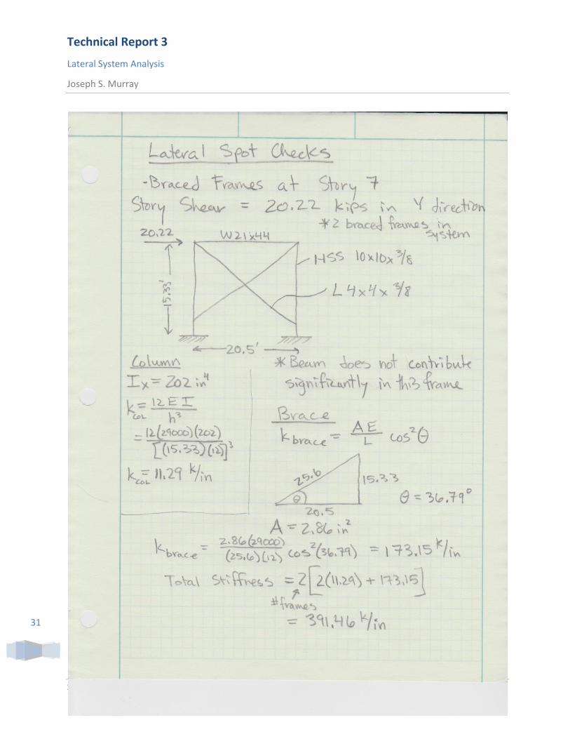
Lateral Spot Checks
Two spot checks were made where drift was the highest. One was made at the penthouse on story 7 in a
braced frame system in the “Y direction”. The braced frames are shown in purple in Figure19. The other
was made on the same level in the “X direction” of a moment frame. The moment frames are shown in
red on Figure 19.
Figure 19: Braced Frames on Story 7
Both the braced frame and the moment frame systems on story 7 met drift requirements. They
compared similarly to the drift values in the RAM output file. The braces, which were designed for a
tension load of 20 kips were adequate for strength. The columns in the moment frame were adequate
for flexure based on a tabulated value from AISC 14th Edition. The calculated results follow.
Technical Report 3
Lateral System Analysis
Joseph S. Murray
S.T.E.P.S. Building Lehigh University Bethlehem, PA
31

Technical Report 3
Lateral System Analysis
Joseph S. Murray
S.T.E.P.S. Building Lehigh University Bethlehem, PA
32

Technical Report 3
Lateral System Analysis
Joseph S. Murray
S.T.E.P.S. Building Lehigh University Bethlehem, PA
33

Technical Report 3
Lateral System Analysis
Joseph S. Murray
S.T.E.P.S. Building Lehigh University Bethlehem, PA
34
Conclusion
The RAM model produced yielded some practical results which were backed up by the lateral spot check
calculations. A computer program should never be trusted blindly; especially one complicated enough to
perform structural analysis. It seems that in this case though, RAM Structural System performed a
relatively accurate analysis that met strength and serviceability requirements established by code. The
frames in the system met drift requirements from ASCE 7-05, and the behavior of the building seemed
realistic.
P-Delta effects are something which will need to be considered in future analysis, as gravity loads were
neglected. They could produce much larger deflections of columns yielding in much larger drifts.
Technical Report 3
Lateral System Analysis
Joseph S. Murray
S.T.E.P.S. Building Lehigh University Bethlehem, PA
35
Appendix A-1

Technical Report 3
Lateral System Analysis
Joseph S. Murray
S.T.E.P.S. Building Lehigh University Bethlehem, PA
36

Technical Report 3
Lateral System Analysis
Joseph S. Murray
S.T.E.P.S. Building Lehigh University Bethlehem, PA
37
Appendix A-2
ASCE 7-05: Section 6.5
V = 90 mph (Figure 6-16)
Occupancy is 1490 > 500 for university, so TYPE III (Table 1-1)
Importance TYPE III; V < 100 mph therefore, I = 1.15 (Table 6-1)
Roughness Type B (Urban/Suburban) (Section 6.5.6.2)
Figure A1: Plan View
Figure A2: East Elevation
E/W: L = 86.9’ B = 275.3’
H = (154)(84’) + (121.3)(65’) = 78’
(154+ 121.3)
N/S: L = 275.3’ B = 86.9’
H = 100’ to be conservative

Technical Report 3
Lateral System Analysis
Joseph S. Murray
S.T.E.P.S. Building Lehigh University Bethlehem, PA
38

Technical Report 3
Lateral System Analysis
Joseph S. Murray
S.T.E.P.S. Building Lehigh University Bethlehem, PA
39