Technical Report 2 - Pennsylvania State University Section 36A James Chavanic Kingstowne, Virginia...
57
Rendering provided by DCS Design Technical Report 2 Kingstowne Section 36A 5680 King Center Drive Kingstowne, VA 22315 James Chavanic Structural Option Advisor: Dr. Boothby October 12, 2012
Transcript of Technical Report 2 - Pennsylvania State University Section 36A James Chavanic Kingstowne, Virginia...

Rendering provided by DCS Design
Technical Report 2
Kingstowne Section 36A
5680 King Center Drive
Kingstowne, VA 22315 James Chavanic
Structural Option
Advisor: Dr. Boothby
October 12, 2012
Kingstowne Section 36A James Chavanic Kingstowne, Virginia Structural Option
October 12th, 2012 Technical Report 2 2
TABLE OF CONTENTS
TABLE OF CONTENTS ..................................................................................................................................... 2
EXECUTIVE SUMMARY .................................................................................................................................. 3
BUILDING INTRODUCTION ............................................................................................................................ 4
STRUCTURAL OVERVIEW .............................................................................................................................. 5
FOUNDATIONS .......................................................................................................................................... 5
GARAGE LEVELS ........................................................................................................................................ 6
OFFICE LEVELS ........................................................................................................................................... 8
ROOF SYSTEM ........................................................................................................................................ 10
DESIGN CODES ............................................................................................................................................ 11
MATERIAL PROPERTIES ............................................................................................................................... 12
GRAVITY LOADS .......................................................................................................................................... 13
DEAD LOADS ........................................................................................................................................... 13
LIVE LOADS .............................................................................................................................................. 13
FLOOR SYSTEM ANALYSIS ........................................................................................................................... 14
TWO-WAY FLAT SLAB WITH DROP PANELS ............................................................................................ 15
PRECAST, PRE-TENSIONED DOUBLE-TEES ON PRECAST, PRESTRESSED GIRDERS .................................. 16
COMPOSITE STEEL DECK ON COMPOSITE BEAMS AND GIRDERS ........................................................... 18
ONE-WAY CONCRETE PAN JOISTS WITH WIDE BEAMS .......................................................................... 20
STEEL FORM DECK ON OPEN-WEB STEEL JOISTS AND WIDE FLANGE GIRDERS ..................................... 22
SUMMARY COMPARISON ........................................................................................................................... 24
CONCLUSION ............................................................................................................................................... 25
APPENDIX: A ................................................................................................................................................ 26
APPENDIX: B ................................................................................................................................................ 31
APPENDIX: C ................................................................................................................................................ 36
APPENDIX: D ................................................................................................................................................ 43
APPENDIX: E ................................................................................................................................................ 45
APPENDIX: F ................................................................................................................................................ 48
APPENDIX: G ............................................................................................................................................... 51
APPENDIX: H................................................................................................................................................ 55

Kingstowne Section 36A James Chavanic Kingstowne, Virginia Structural Option
October 12th, 2012 Technical Report 2 3
EXECUTIVE SUMMARY
Kingstowne Section 36A (KT36A) is a 200,000 SF mixed use building currently being constructed in
Fairfax County Virginia. When completed, the lower half of the building will serve as a parking garage
serving the office tenants of the upper half of the building. The parking garage levels utilize flat slab
concrete construction while the office levels use a composite steel construction. A more thorough
description of the existing structure can be found in the first half of this report.
The purpose of Technical Report 2 is to analyze the existing floor systems of KT36A and perform a pro-
con study on three alternative floor systems that are believed to be possible candidates for
consideration in the building. The alternative floor systems must be schematically designed so that an
accurate comparison considering, strength, deflections, structure depth, system weight, lateral system
impacts, foundation impacts, and costs can be made. A summary of the system comparison can be
found in Figure 17 on page 25 of this report. The floor systems considered for comparison were:
Two-way Flat Slab With Drop Panels (Garage Existing)
Precast, Pretensioned Double Tees on Precast, Pretensioned Support Girders
Composite Steel Deck on Composite Steel Beams and Girders (Office Existing)
One-way Concrete Pan Joists With Wide Beams
Steel Form Deck on Open-web Steel Joists and Wide Flange Girders
After conducting the analyses of the systems, it was clearer why a split structure was chosen for the
building. Concrete was a good choice for the parking levels due to the minimal structural depth and the
durability of concrete when exposed to a wet and salty environment. The composite steel construction
in the office levels allowed large open bays for maximum flexibility of the office space. Of the
alternative systems considered, the open web steel joist system seems to be the most probable
alternative to the existing office level framing. Changing to this system would have virtually no impact
on the existing systems since the weight is about the same and the braced and moment frames can still
be used for the lateral system at the office levels. The precast double tee system is a possible
alternative for the garage levels. Use of this system would allow for two lines of columns to be removed
at grid lines B and E. However, lateral system impact from this alternative can be quite severe
considering the designed lateral system consists of cast in place shear walls which typically frame into
the cast in place columns. As for the one way concrete pan joist system, it appears that unless if the bay
sizes can be made a little smaller, this system is simply too heavy and bulky to efficient construct the
building with.

Kingstowne Section 36A James Chavanic Kingstowne, Virginia Structural Option
October 12th, 2012 Technical Report 2 4
BUILDING INTRODUCTION
Kingstowne Section 36A (KT36A) is a 200,000 ft2, 8 story office building to be located in Fairfax County
Virginia. It will contain 4 levels of concrete structure parking garage and 4 levels of composite steel
construction office space. Floor space has also been allocated for about 5,000 square feet of retail area
on the ground floor (Parking Level 1). KT36A will be 86’-11” in height when measured from the average
grade. The reason the building height is measured from average grade is because there is a significant
grade elevation change from the south side of the building to the north side, on the order of 26’-8” (See
Figure 1). This poses unique challenges in the structural design of the building since the geotechnical
report states the soil placing a load of 60psf/ft in depth below grade surface on the structure. This
means that there is more than 1600 psf of soil load on the foundation walls at the lowest slab levels.
This load alone had enough impact on the building that six 12” thick shear walls had to be constructed at
parking level 1 to transfer the loads safely.
When completed, KT36A will be part of a master planned development for retail and office space owned
by the Halle Companies. Being a part of a master planned development, the building was designed to
match the appearance of the surrounding buildings. This appearance can be characterized by a
rectilinear footprint, pink velour brick, aluminum storefront with glass of blue/black appearance, and
precast concrete bands around the circumference of the building.
Figure 1: Elevation Looking East Showing Grade Differences (Source: DCS Design Drawing A-301)
Kingstowne Section 36A James Chavanic Kingstowne, Virginia Structural Option
October 12th, 2012 Technical Report 2 5
STRUCTURAL OVERVIEW
Kingstowne Section 36A consists of two different primary structural systems; cast-in-place concrete for
the lowest four floors of the building and a composite steel system for the remaining four floors. The
concrete floors are used for the parking garage and retail space while the steel system is used at the
office occupancy levels. Lateral forces in the concrete levels are resisted with 12” thick concrete shear
walls of varying height. When the building transitions to steel construction, lateral forces are
transferred to the concrete columns and shear walls through concentrically braced frames, eccentrically
braced frames, and rigid moment frames. Per sheet S-001, components such as steel stairs and curtain
wall/window systems were not included in the scope for the structural design of this building.
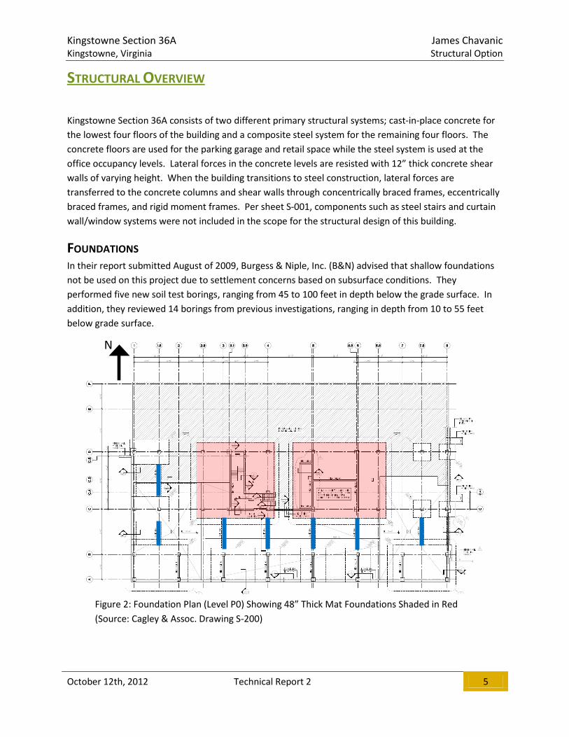
FOUNDATIONS
In their report submitted August of 2009, Burgess & Niple, Inc. (B&N) advised that shallow foundations
not be used on this project due to settlement concerns based on subsurface conditions. They
performed five new soil test borings, ranging from 45 to 100 feet in depth below the grade surface. In
addition, they reviewed 14 borings from previous investigations, ranging in depth from 10 to 55 feet
below grade surface.
Figure 2: Foundation Plan (Level P0) Showing 48” Thick Mat Foundations Shaded in Red
(Source: Cagley & Assoc. Drawing S-200)
N

Kingstowne Section 36A James Chavanic Kingstowne, Virginia Structural Option
October 12th, 2012 Technical Report 2 6
Each of the borings found lean clay and fat clay fills with varying amounts of sand, residual soils
consisting of lean to fat clay, and clayey to silty sands. Based on the fill materials being encountered
between 4 and 48 feet below grade, B&N offered two foundation options. An intermediate foundation
system consisting of spread and strip footings bearing on rammed aggregate piers (Geopiers) was
chosen for KT36A over the alternate option of a deep system consisting of spread and strip footings
bearing on caissons. Geopier diameters typically range from 24 to 36 inches and are compacted using a
special high-energy impact hammer with a 45-degree beveled tamper. Per B&N report, footings
supported by Geopier elements can be designed using a maximum bearing pressure of 7,000 psf.
Using the information provided by B&N, Cagley & Associates designed spread footings ranging from 27”
to 44” in depth to support the columns of KT36A. 48” thick mat foundations bearing on Geopiers are
located at the central core of the building to transfer forces in the main shear walls to the soil (See
Figure 2). Grade beams (Blue lines in Figure 2) of 30” depth are used throughout level P0 to also
transfer forces from the shear walls to the column footings. Foundation walls are supported by
continuous wall footings designed for an allowable bearing pressure of 2,500 psf. All foundations are to
bear a minimum of 30” below grade unless stated otherwise.
GARAGE LEVELS
FLOOR SYSTEM
As previously mentioned, KT36A utilizes cast-in-place concrete for the support structure in the garage.
With the exception of the 5” thick slab on grade, this system consists of 8” thick two-way, flat slab
construction with drop panels that project 8” below the bottom of structural slab. The drop panels are
continuous between grid lines C and D to help the slab span the increased distance of 36’-6” in this bay,
otherwise, they are typically 10’-0” x 10’-0” in size. Due to the need for vehicles to circulate vertically
throughout the parking garage levels, the floor is sloped on 3 sides of the central core to achieve this.
Since a two-way, flat plate concrete floor system is
subjected to both positive and negative moments,
reinforcing steel is required in the top and bottom of the
slab. The typical bottom mat of reinforcement in KT36A
consists of #4 bars spaced at 12” on center in each
direction of the slab. Additional bottom reinforcement
in certain middle strips and continuous drop panels is
also noted on the drawings. Top reinforcement is
comprised of both #5 and #6 bars, both oriented in the
same fashion as the bottom mat, with the #6 bars
typically being used in the column strips to resist the
larger negative moments present there (see Figure 3 for
a typical bay layout). A typical bay size for the concrete
levels is 28’-6” x 29’-0”. Figure 3: Partial Plan Level P1 (Source: Cagley
& Assoc. Drawing S-201)

Kingstowne Section 36A James Chavanic Kingstowne, Virginia Structural Option
October 12th, 2012 Technical Report 2 7
FRAMING SYSTEM
Supporting the floor slabs are cast-in-place concrete columns constructed of 5000 psi concrete. The
most common column size is 24” x 24” reinforced with a varying number of #8 bars and either #3 or #4
ties. Columns of this size primarily account for the gravity resisting system of KT36A. The largest
columns used are 36” x 30” reinforced with a varying number of #11 bars and #4 stirrups. The larger
columns are located at the ends of the large shear walls in the central core of the building. A small
number of concrete beams are also present in the project, typically at areas of the perimeter where
additional façade support was needed and at large protrusions in the floor slab.
LATERAL SYSTEM
Cast-in-place concrete shear walls resist the lateral forces present in the parking garage levels of KT36A.
All of the twelve walls present in the building are 12” thick and cast using 5000 psi concrete. Six of the
shear walls (#1 - #6, see Red lines in Figure 4) extend 4-5 stories from the 48” thick mat foundations to
office level 1 which is also the 5th elevated floor of the building. Three of the six walls are oriented to
resist lateral forces in the N-S direction while the other three walls are oriented in the E-W direction.
The remaining six walls (#7 - #12, Green lines in Figure 4) are only one story tall and are oriented to best
resist the unique lateral soil load placed on KT36A. This load condition is further detailed in the lateral
loads section of this report and will be further analyzed in Technical Report 3.
Figure 4: Foundation Plan (Level P0) Showing Shear Walls (Source: Cagley & Assoc. Drawing S-200)
N

Kingstowne Section 36A James Chavanic Kingstowne, Virginia Structural Option
October 12th, 2012 Technical Report 2 8
OFFICE LEVELS
FLOOR SYSTEM
Office level 1 is constructed of the same cast-in-place style of construction as the garage floors below it
with the exception of the top of slab elevation being uniform throughout the floor. The remaining floors
are constructed using a composite steel system. This system is comprised of 3 ¼” thick lightweight
concrete on 2” x 18 gage galvanized composite steel decking. The 3000 psi lightweight concrete (115
pcf) coupled with the decking yields a total slab thickness of 5 ¼”. Reinforcement for the slab is
provided by 6x6-W2.1xW2.1 welded wire fabric.
According to sheet S-001, all decking should meet the three span continuous condition. The decking
typically spans 9’-6” perpendicular to cambered beams of varying size. Shear studs of ¾” diameter
placed along the length of the beams make this a composite system capable of more efficiently carrying
the loads when compared to a non-composite system. The studs must be minimum length of 3 ½” but
no longer than 4 ½” to meet designer and code requirements.
FRAMING SYSTEM
The composite floor system mentioned above is supported by structural steel framing comprised of
primarily wide flange shapes. W21’s and W18’s account for most of the beams while the columns range
in size from W12x40 to W14x109. A majority of the beams in KT36A are cambered between ¾” and
1 ¼”, a function of the span and load demand on the beams. With the exception of four W30x99
sections cambered 1”, most of the girders fall within the same size range as the beams. The four
W30x99 girders each span 44’-0” which warrants the use of the camber to satisfy the total deflection
criteria. The columns are all spliced just above the 7th floor (office level 3) where they are reduced in
size to more economically carry the lighter axial loads. See Figure 5 below for a typical office floor level
layout.
Figure 5: Typical Composite Slab Partial Plan (Level OL3) (Source: Cagley & Assoc. Drawing S-207)
N
Kingstowne Section 36A James Chavanic Kingstowne, Virginia Structural Option
October 12th, 2012 Technical Report 2 9
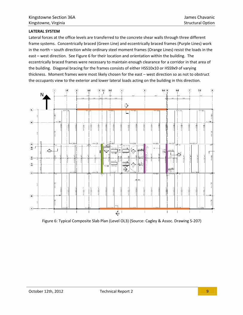
LATERAL SYSTEM
Lateral forces at the office levels are transferred to the concrete shear walls through three different
frame systems. Concentrically braced (Green Line) and eccentrically braced frames (Purple Lines) work
in the north – south direction while ordinary steel moment frames (Orange Lines) resist the loads in the
east – west direction. See Figure 6 for their location and orientation within the building. The
eccentrically braced frames were necessary to maintain enough clearance for a corridor in that area of
the building. Diagonal bracing for the frames consists of either HSS10x10 or HSS9x9 of varying
thickness. Moment frames were most likely chosen for the east – west direction so as not to obstruct
the occupants view to the exterior and lower lateral loads acting on the building in this direction.
Figure 6: Typical Composite Slab Plan (Level OL3) (Source: Cagley & Assoc. Drawing S-207)
N

Kingstowne Section 36A James Chavanic Kingstowne, Virginia Structural Option
October 12th, 2012 Technical Report 2 10
ROOF SYSTEM
The roofing system consists of a white EPDM membrane fully adhered over 6” minimum of R-30
continuous rigid roof insulation. The seams of the membrane must be lapped a minimum of 3” to
ensure a watertight seal. Where mechanical equipment is located (see Figure 9), the roofing materials
are supported by 2”x 18GA galvanized composite steel deck with a 3.25” thick light-weight concrete
topping. The load carrying capacity that this type offers is required to support the four 17,000lb roof
top mechanical units needed to condition the air for the building occupants. In all other areas of the
roof, the system is supported by 3”x 20GA type N roof deck. Each of the roof types are supported by
steel W-shapes that are sloped to achieve proper drainage.
Figures 7 and 8: Typical Roofing Details (Source: DCS Design Drawing A-410)
Mechanical Area
Screen wall Perimeter
Figure 9: Structural Roof Plan (Source: Cagley & Assoc. Drawing S-209)
Kingstowne Section 36A James Chavanic Kingstowne, Virginia Structural Option
October 12th, 2012 Technical Report 2 11
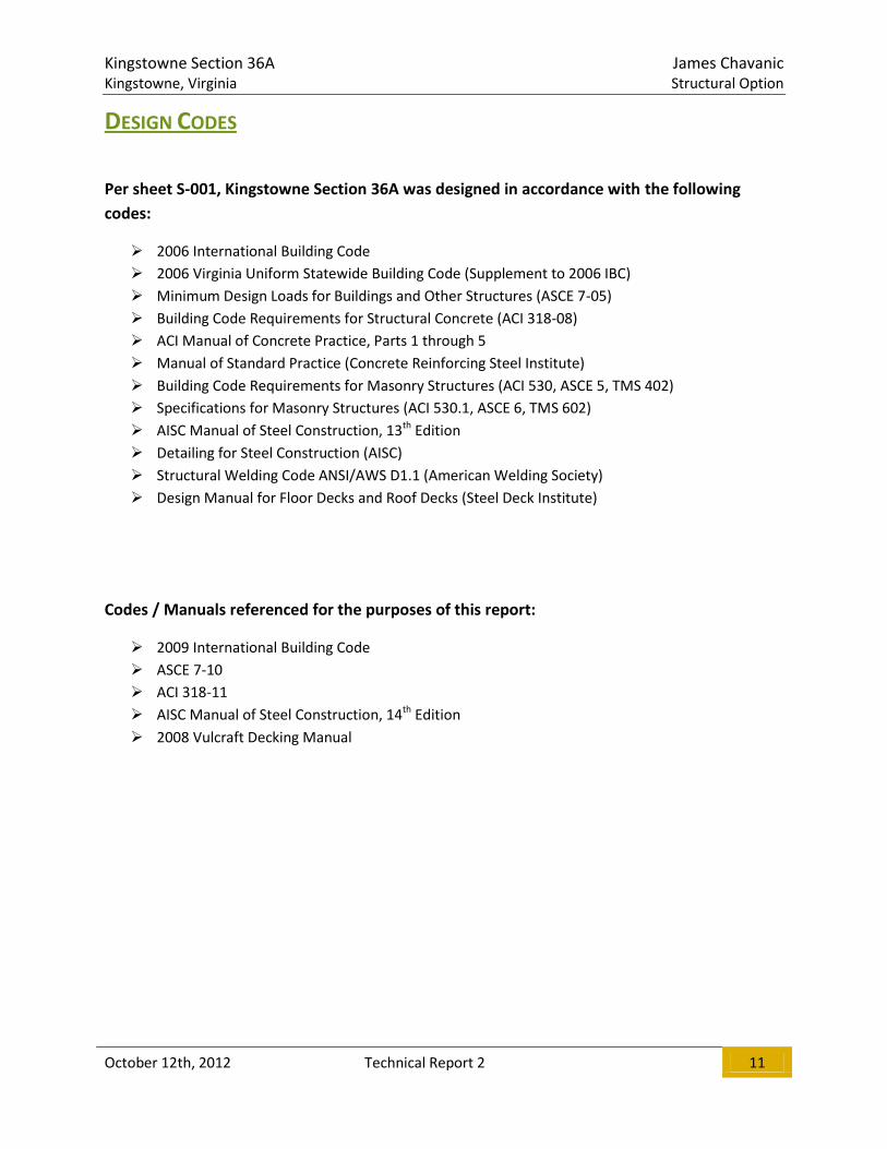
DESIGN CODES
Per sheet S-001, Kingstowne Section 36A was designed in accordance with the following
codes:
2006 International Building Code
2006 Virginia Uniform Statewide Building Code (Supplement to 2006 IBC)
Minimum Design Loads for Buildings and Other Structures (ASCE 7-05)
Building Code Requirements for Structural Concrete (ACI 318-08)
ACI Manual of Concrete Practice, Parts 1 through 5
Manual of Standard Practice (Concrete Reinforcing Steel Institute)
Building Code Requirements for Masonry Structures (ACI 530, ASCE 5, TMS 402)
Specifications for Masonry Structures (ACI 530.1, ASCE 6, TMS 602)
AISC Manual of Steel Construction, 13th Edition
Detailing for Steel Construction (AISC)
Structural Welding Code ANSI/AWS D1.1 (American Welding Society)
Design Manual for Floor Decks and Roof Decks (Steel Deck Institute)
Codes / Manuals referenced for the purposes of this report:
2009 International Building Code
ASCE 7-10
ACI 318-11
AISC Manual of Steel Construction, 14th Edition
2008 Vulcraft Decking Manual
Kingstowne Section 36A James Chavanic Kingstowne, Virginia Structural Option
October 12th, 2012 Technical Report 2 12
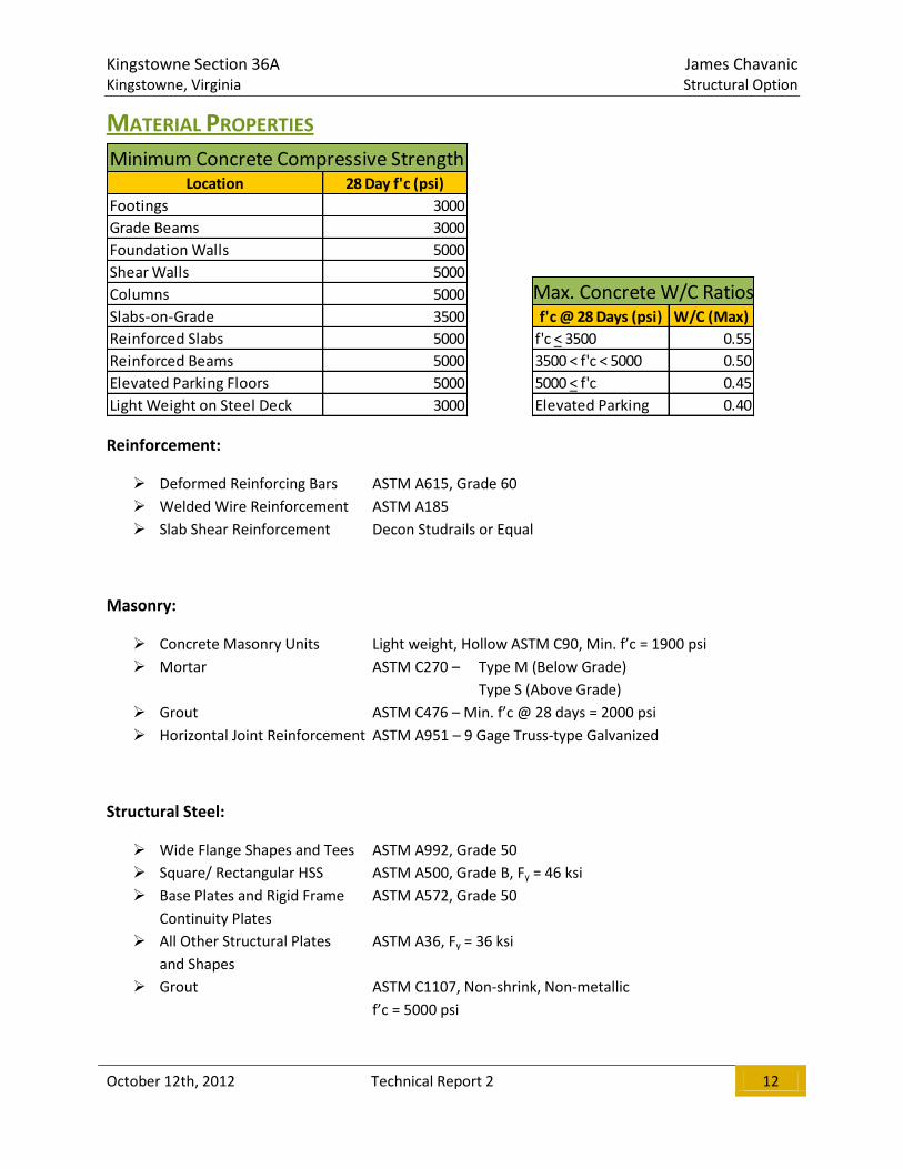
MATERIAL PROPERTIES
Reinforcement:
Deformed Reinforcing Bars ASTM A615, Grade 60
Welded Wire Reinforcement ASTM A185
Slab Shear Reinforcement Decon Studrails or Equal
Masonry:
Concrete Masonry Units Light weight, Hollow ASTM C90, Min. f’c = 1900 psi
Mortar ASTM C270 – Type M (Below Grade)
Type S (Above Grade)
Grout ASTM C476 – Min. f’c @ 28 days = 2000 psi
Horizontal Joint Reinforcement ASTM A951 – 9 Gage Truss-type Galvanized
Structural Steel:
Wide Flange Shapes and Tees ASTM A992, Grade 50
Square/ Rectangular HSS ASTM A500, Grade B, Fy = 46 ksi
Base Plates and Rigid Frame ASTM A572, Grade 50
Continuity Plates
All Other Structural Plates ASTM A36, Fy = 36 ksi
and Shapes
Grout ASTM C1107, Non-shrink, Non-metallic
f’c = 5000 psi
Location 28 Day f'c (psi)
Footings 3000
Grade Beams 3000
Foundation Walls 5000
Shear Walls 5000
Columns 5000
Slabs-on-Grade 3500
Reinforced Slabs 5000
Reinforced Beams 5000
Elevated Parking Floors 5000
Light Weight on Steel Deck 3000
Minimum Concrete Compressive Strength
f'c @ 28 Days (psi) W/C (Max)
f'c < 3500 0.55
3500 < f'c < 5000 0.50
5000 < f'c 0.45
Elevated Parking 0.40
Max. Concrete W/C Ratios

Kingstowne Section 36A James Chavanic Kingstowne, Virginia Structural Option
October 12th, 2012 Technical Report 2 13
GRAVITY LOADS
DEAD LOADS
Dead loads resulting from system self-weights were calculated and estimated based on the drawings
provided. The loads and the assumptions used in their determination are detailed in Appendix A.
LIVE LOADS
Plan Area Load (psf)
Office Floors 15
Roof 30
Parking Garage Floors 5
Superimposed Dead Loads
Plan Area Design Load (psf) IBC Load (psf) Notes
Lobbies 100 100
Mechanical 150 N/A Non-reducible
Offices 80 80 Corridors used, otherwise 50 psf
Office Partitions 20 15 Minimum per section 1607.5
Parking Garage 50 40
Retail 100 100 Located on first floor
Stairs and Exitways 100 100 Non-reducible
Storage (Light) 125 125 Non-reducible
Roof Load 30 20
Live Loads

Kingstowne Section 36A James Chavanic Kingstowne, Virginia Structural Option
October 12th, 2012 Technical Report 2 14
FLOOR SYSTEM ANALYSIS
The typical structural bay for Kingstowne 36A depends on what level of the building is being considered.
At the garage levels, the bay size is commonly 27’-6” to 29’-0” by 28’-6” to 29’-0”. Smaller bays and
larger bays do exist, but this is the most common range. See Figure 10 for the garage bay used for the
purposes of this report. As for the office levels, grid lines B and E terminate when the concrete structure
is no longer used resulting in a typical bay size of 28’-6” to 29’-0” by 43’-6” to 45’-0”. Again, smaller and
larger bays do exist, but this is the most typical range. See Figure 11 for the office bay used for the
purposes of this report.
Please note that only gravity loads were used for the purposes of this report. In order to properly
estimate and understand the proposed floor systems, a lateral analysis for each system would also have
to be completed. This, however, was not part of the scope of this report.
Figure 10: Typical Garage Bay (Level PL2)
(Source: Cagley & Assoc. Drawing S-203)
Figure 11: Typical Office Bay (Level OL3)
(Source: Cagley & Assoc. Drawing S-207)

Kingstowne Section 36A James Chavanic Kingstowne, Virginia Structural Option
October 12th, 2012 Technical Report 2 15
TWO-WAY FLAT SLAB WITH DROP PANELS
DESCRIPTION
The existing floor system used for the garage levels consists of an 8 inch thick 2-way flat slab with 8 inch
thick drop panels at the columns. The drop panels are typically 10’ by 10’ and help to increase the
punching shear capacity of the slab at the columns. Concrete with a compressive strength of 5000 psi
and grade 60 reinforcement were used to construct the cast-in-place structure. Typical reinforcing for
the bottom of the slab consists of #4 bars at 12” O.C each way. Top reinforcing for the slab typically
consists of #5 and #6 bars.
ADVANTAGES
Probably the most attractive feature of the flat slab is its ability to carry loads with absolutely minimal
structural depth. This allows for a small floor to floor height, even after the mechanical systems are
placed below the structure. The flat slab system typically has enough weight to it that vibrations are not
a concern. Since there is so much flat surface area with this type of structure, formwork is generally
simple and cheap when compared to concrete systems with beams and girders. This also eases
constructability thus speeding up the construction time for this type of structure. Thanks to the
inherent properties of the concrete, this system does not require additional fire-proofing to meet the 2
hour requirement.
DISADVANTAGES
The two-way flat slab is a significantly heavier system than any typical steel framing floor system. While
not having an effect on KT36A, this extra weight could pose an issue at foundations if the flat slab
system is being considered to replace a lighter existing system. Additionally, formwork required to cast
the concrete is a cost that doesn’t directly contribute to the strength of the floor system.
Figure 12: Typical Section at Column Strip (Source: Cagley & Assoc. Drawing S-410)
Kingstowne Section 36A James Chavanic Kingstowne, Virginia Structural Option
October 12th, 2012 Technical Report 2 16
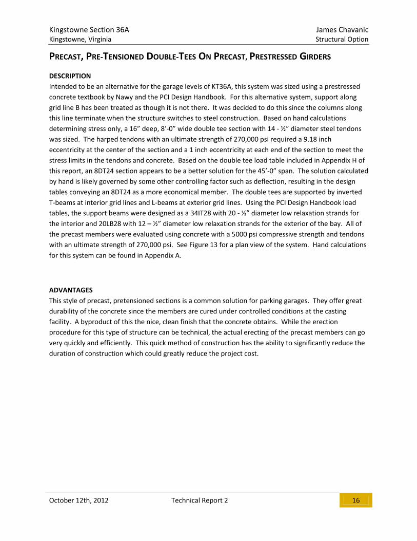
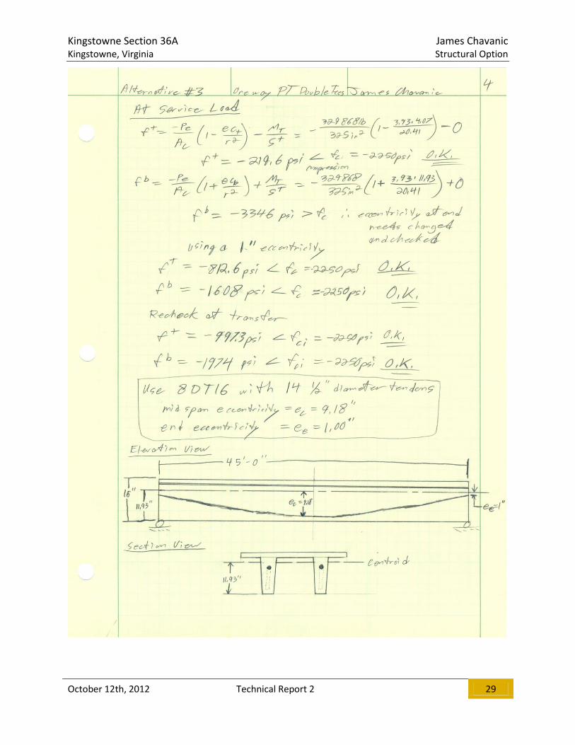
PRECAST, PRE-TENSIONED DOUBLE-TEES ON PRECAST, PRESTRESSED GIRDERS
DESCRIPTION
Intended to be an alternative for the garage levels of KT36A, this system was sized using a prestressed
concrete textbook by Nawy and the PCI Design Handbook. For this alternative system, support along
grid line B has been treated as though it is not there. It was decided to do this since the columns along
this line terminate when the structure switches to steel construction. Based on hand calculations
determining stress only, a 16” deep, 8’-0” wide double tee section with 14 - ½” diameter steel tendons
was sized. The harped tendons with an ultimate strength of 270,000 psi required a 9.18 inch
eccentricity at the center of the section and a 1 inch eccentricity at each end of the section to meet the
stress limits in the tendons and concrete. Based on the double tee load table included in Appendix H of
this report, an 8DT24 section appears to be a better solution for the 45’-0” span. The solution calculated
by hand is likely governed by some other controlling factor such as deflection, resulting in the design
tables conveying an 8DT24 as a more economical member. The double tees are supported by inverted
T-beams at interior grid lines and L-beams at exterior grid lines. Using the PCI Design Handbook load
tables, the support beams were designed as a 34IT28 with 20 - ½” diameter low relaxation strands for
the interior and 20LB28 with 12 – ½” diameter low relaxation strands for the exterior of the bay. All of
the precast members were evaluated using concrete with a 5000 psi compressive strength and tendons
with an ultimate strength of 270,000 psi. See Figure 13 for a plan view of the system. Hand calculations
for this system can be found in Appendix A.
ADVANTAGES
This style of precast, pretensioned sections is a common solution for parking garages. They offer great
durability of the concrete since the members are cured under controlled conditions at the casting
facility. A byproduct of this the nice, clean finish that the concrete obtains. While the erection
procedure for this type of structure can be technical, the actual erecting of the precast members can go
very quickly and efficiently. This quick method of construction has the ability to significantly reduce the
duration of construction which could greatly reduce the project cost.

Kingstowne Section 36A James Chavanic Kingstowne, Virginia Structural Option
October 12th, 2012 Technical Report 2 17
DISADVANTAGES
As previously mentioned, erection of precast concrete structures can become quite technical. To start,
two structural engineers are typically contracted in a precast concrete job, one to design the precast
itself and one to design the foundations to support the precast. Precast structures are also poor
performers against heavy lateral loads. A large lateral soil load is present in KT36A that would require
careful consideration if this system was chosen to be designed. This load also works in conjunction with
the controlling wind loads to make for an even more heavily loaded system.
Figure 13: Schematic Double Tee Layout (Source: Chavanic)
Kingstowne Section 36A James Chavanic Kingstowne, Virginia Structural Option
October 12th, 2012 Technical Report 2 18
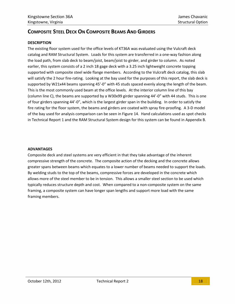
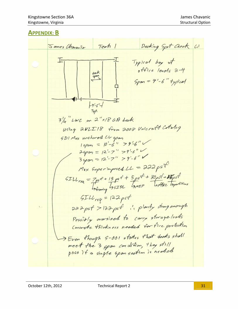
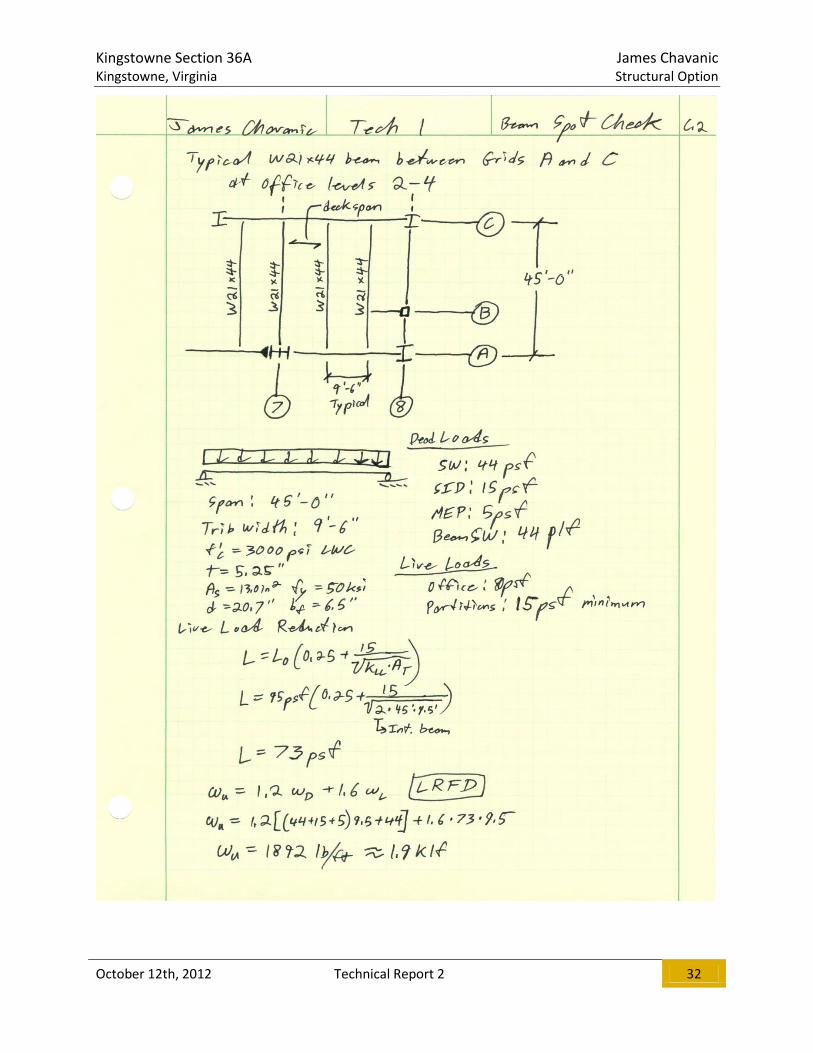
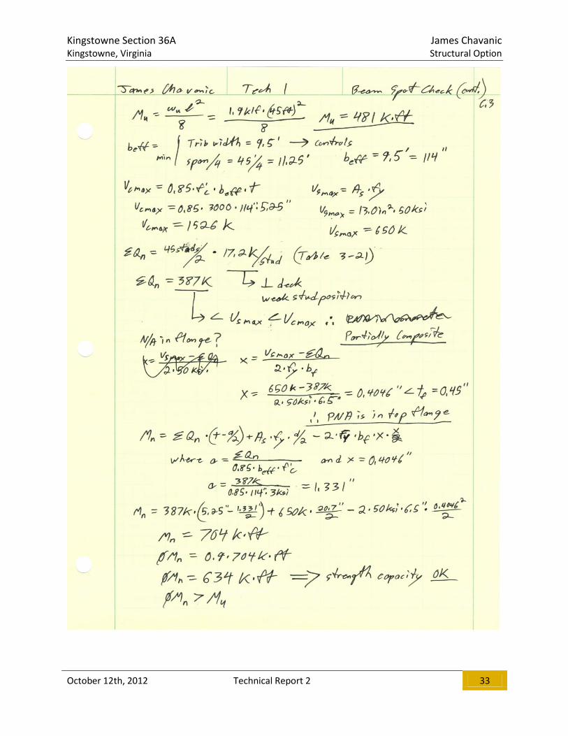
COMPOSITE STEEL DECK ON COMPOSITE BEAMS AND GIRDERS
DESCRIPTION
The existing floor system used for the office levels of KT36A was evaluated using the Vulcraft deck
catalog and RAM Structural System. Loads for this system are transferred in a one-way fashion along
the load path, from slab deck to beam/joist, beam/joist to girder, and girder to column. As noted
earlier, this system consists of a 2 inch 18 gage deck with a 3.25 inch lightweight concrete topping
supported with composite steel wide flange members. According to the Vulcraft deck catalog, this slab
will satisfy the 2 hour fire-rating. Looking at the bay used for the purposes of this report, the slab deck is
supported by W21x44 beams spanning 45’-0” with 45 studs spaced evenly along the length of the beam.
This is the most commonly used beam at the office levels. At the interior column line of this bay
(column line C), the beams are supported by a W30x99 girder spanning 44’-0” with 44 studs. This is one
of four girders spanning 44’-0”, which is the largest girder span in the building. In order to satisfy the
fire rating for the floor system, the beams and girders are coated with spray fire-proofing. A 3-D model
of the bay used for analysis comparison can be seen in Figure 14. Hand calculations used as spot checks
in Technical Report 1 and the RAM Structural System design for this system can be found in Appendix B.
ADVANTAGES
Composite deck and steel systems are very efficient in that they take advantage of the inherent
compressive strength of the concrete. The composite action of the decking and the concrete allows
greater spans between beams which equates to a lower number of beams needed to support the loads.
By welding studs to the top of the beams, compressive forces are developed in the concrete which
allows more of the steel member to be in tension. This allows a smaller steel section to be used which
typically reduces structure depth and cost. When compared to a non-composite system on the same
framing, a composite system can have longer span lengths and support more load with the same
framing members.

Kingstowne Section 36A James Chavanic Kingstowne, Virginia Structural Option
October 12th, 2012 Technical Report 2 19
DISADVANTAGES
When compared to a non-composite system, a composite system requires more time, labor, and
inspections due to the shear studs being installed after the steel is erected and the deck has been laid
down. The slab deck is typically controlled by the required fire rating; however, the supporting beams
and girders must also meet this fire rating. In order to achieve this, spray fire-proofing is typically
applied to the beams and girders. An alternative to this style of fire-proofing is using a gypsum board
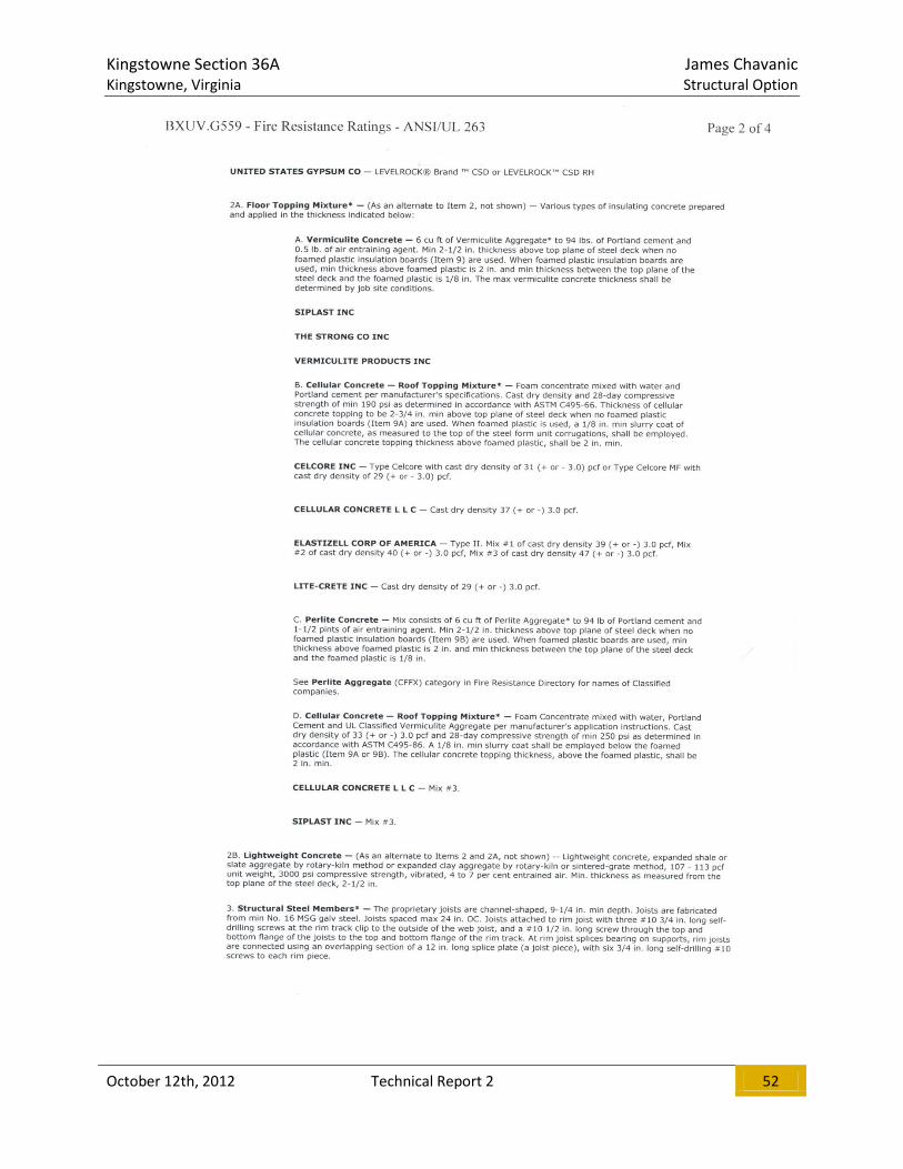
ceiling with batt insulation. A similar Underwriters Laboratories assembly can be seen in Appendix G
(this assembly uses a steel joist instead of a rolled section).
Figure 14: Model of Existing Office Level Bay Framing (Source: Chavanic)

Kingstowne Section 36A James Chavanic Kingstowne, Virginia Structural Option
October 12th, 2012 Technical Report 2 20
ONE-WAY CONCRETE PAN JOISTS WITH WIDE BEAMS
DESCRIPTION
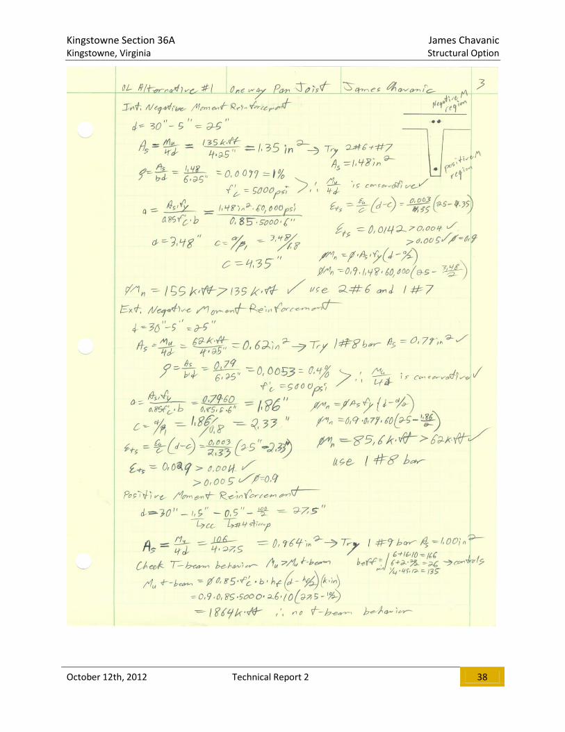
Intended as an alternative for the office floors of the building, this system was developed using ACI 318-
11 provisions and standard pan joist dimensions. The joists span the 45’-0” long direction of the bay and
are formed using 20 inch pans. Choosing a 6 inch joist width yields a 26 inch on center spacing of the
joists. To meet the 2 hour fire rating requirement, a 4.5 inch thick one-way slab was chosen as the trial
slab size. After checking the minimum thickness required to meet deflection criteria in ACI 318-11 Table
9.5(a), it was determined that a total system depth of 30 inches is needed to adequately span the 45’-0”.
Due to the standard joist pans being available in a maximum depth of 20 inches, a 10 inch solid slab is
needed to make up the required depth of the system. Loads are transferred from the joists to the
columns through wide beam girders that were constrained to the same depth of the joist and slab
combination. To remain consistent with the design parameters used at the garage levels, concrete with
a compressive strength of 5000 psi and grade 60 reinforcement were selected for use in the design.
Assuming one-way action in the slab, joist, and wide beam girder, reinforcement was designed based on
the loads seen at the office floors. Analysis of the slab resulted in minimum steel for temperature and
shrinkage controlling. For this, 1 #3 bar at 6 inches on center placed at the center of the slab was
specified. Reinforcing for the joists was found to be 2 #6 bars and 1 #7 bar at the interior negative
moment region, 1 #8 bar at the exterior negative moment region, and 1 #9 bar at the positive moment
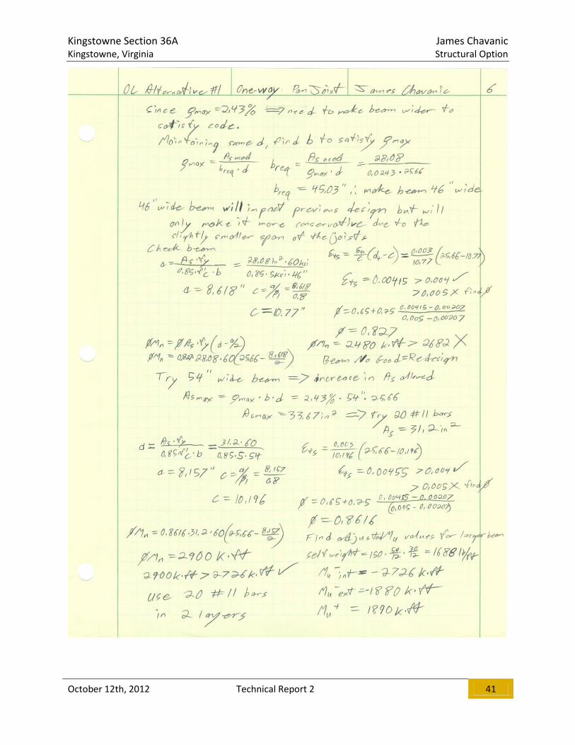
region of the joist. The interior 44’-0” span girder was designed for this system as it is the controlling
girder span present. After a couple of design iterations, a 30 inch deep by 54 inch wide rectangular
section was found to carry the loads. Required reinforcement for the girder was found to be 20 #11
bars in 2 layers at the interior negative moment region of the girder, and 20 #9 bars in 2 layers at the
positive moment and exterior negative moment regions of the girder.
Considering the excessive weight of this structural floor system and the significant impacts it would have
on the building foundations, it was deemed not feasible for this application. However, with a
consideration to reducing bay sizes, this floor system could become an economical option for KT36A.
This system could also be a potential alternative at the parking garage levels which also warrants
reconsidering its feasibility. A plan view of the proposed layout can be seen in Figure 15. Hand
calculations for this system can be found in Appendix C.
ADVANTAGES
A one-way concrete pan joist system can be very effective at spanning large distances, just not ones
quite as long as the 45’-0” spans in KT36A. The shear massiveness of the system allows vibration
considerations to essentially be ignored. In addition to the voids creating the joists reducing the self-
weight of the system, they also allow space for routing mechanical ducts. Since the concrete has
inherent fire-proofing, additional spray fire-proofing is not necessary for this type of system, reducing
the overall cost of the floor.

Kingstowne Section 36A James Chavanic Kingstowne, Virginia Structural Option
October 12th, 2012 Technical Report 2 21
DISADVANTAGES
While the massiveness of the system is great for dampening floor vibrations, it causes some major
drawbacks with the rest of the building. In order to support all of the weight, concrete columns will
have to increase in size and contain heavier amounts of reinforcement. This directly leads to foundation
redesign in order to support the increased loads. In the case of KT36A, the intermediate foundation
system consisting of spread footings bearing on rammed aggregate piers will most likely have to be
changed to a more expensive, deep foundation system. The significant increase in weight will also affect
the forces induced on the building from seismic ground motion. Said forces may increase enough to
make the seismic loading control over the wind loading which would then affect the design of the lateral
system.
Figure 15: Schematic Layout of One-way Concrete Pan Joist System (Source: Chavanic)
Kingstowne Section 36A James Chavanic Kingstowne, Virginia Structural Option
October 12th, 2012 Technical Report 2 22
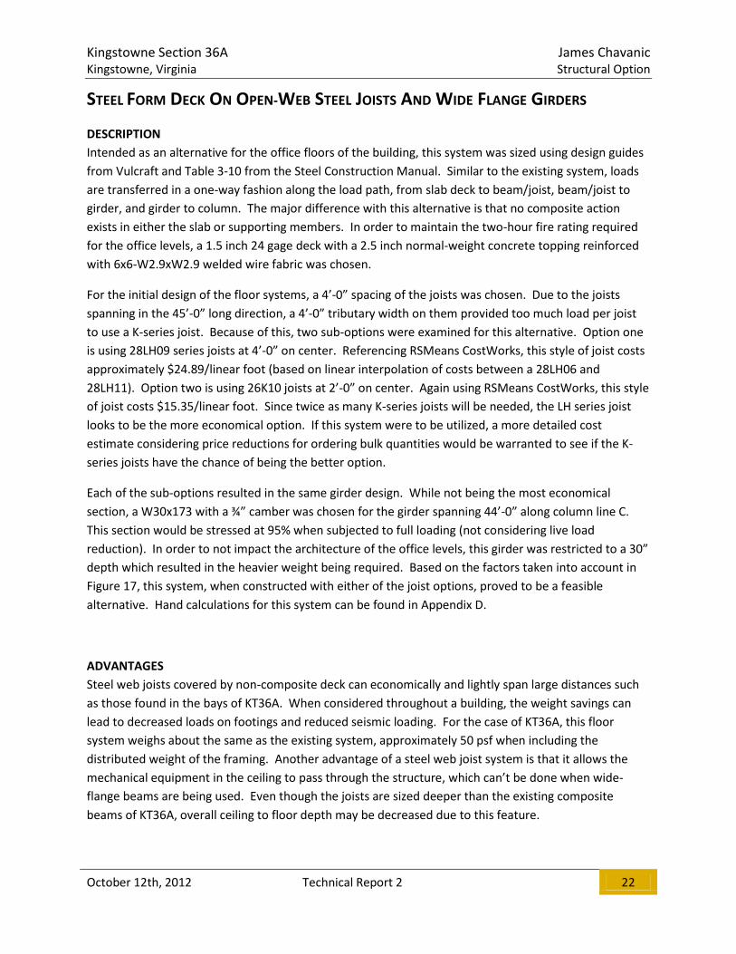
STEEL FORM DECK ON OPEN-WEB STEEL JOISTS AND WIDE FLANGE GIRDERS
DESCRIPTION
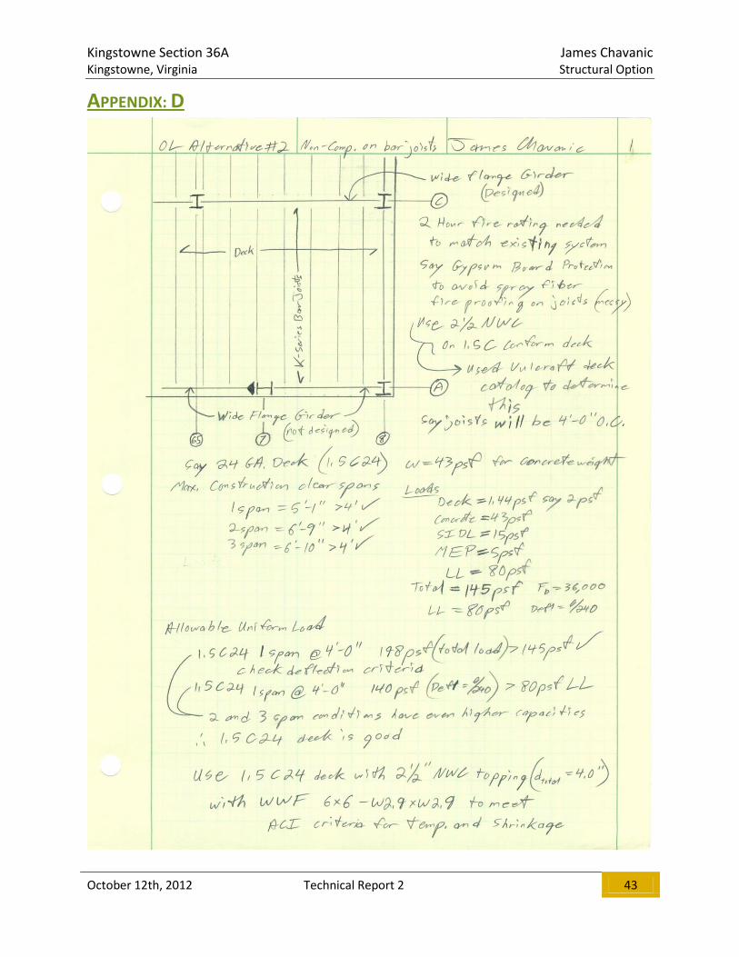
Intended as an alternative for the office floors of the building, this system was sized using design guides
from Vulcraft and Table 3-10 from the Steel Construction Manual. Similar to the existing system, loads
are transferred in a one-way fashion along the load path, from slab deck to beam/joist, beam/joist to
girder, and girder to column. The major difference with this alternative is that no composite action
exists in either the slab or supporting members. In order to maintain the two-hour fire rating required
for the office levels, a 1.5 inch 24 gage deck with a 2.5 inch normal-weight concrete topping reinforced
with 6x6-W2.9xW2.9 welded wire fabric was chosen.
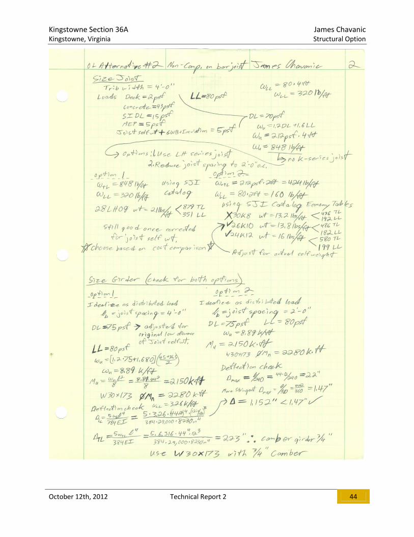
For the initial design of the floor systems, a 4’-0” spacing of the joists was chosen. Due to the joists
spanning in the 45’-0” long direction, a 4’-0” tributary width on them provided too much load per joist
to use a K-series joist. Because of this, two sub-options were examined for this alternative. Option one
is using 28LH09 series joists at 4’-0” on center. Referencing RSMeans CostWorks, this style of joist costs
approximately $24.89/linear foot (based on linear interpolation of costs between a 28LH06 and
28LH11). Option two is using 26K10 joists at 2’-0” on center. Again using RSMeans CostWorks, this style
of joist costs $15.35/linear foot. Since twice as many K-series joists will be needed, the LH series joist
looks to be the more economical option. If this system were to be utilized, a more detailed cost
estimate considering price reductions for ordering bulk quantities would be warranted to see if the K-
series joists have the chance of being the better option.
Each of the sub-options resulted in the same girder design. While not being the most economical
section, a W30x173 with a ¾” camber was chosen for the girder spanning 44’-0” along column line C.
This section would be stressed at 95% when subjected to full loading (not considering live load
reduction). In order to not impact the architecture of the office levels, this girder was restricted to a 30”
depth which resulted in the heavier weight being required. Based on the factors taken into account in
Figure 17, this system, when constructed with either of the joist options, proved to be a feasible
alternative. Hand calculations for this system can be found in Appendix D.
ADVANTAGES
Steel web joists covered by non-composite deck can economically and lightly span large distances such
as those found in the bays of KT36A. When considered throughout a building, the weight savings can
lead to decreased loads on footings and reduced seismic loading. For the case of KT36A, this floor
system weighs about the same as the existing system, approximately 50 psf when including the
distributed weight of the framing. Another advantage of a steel web joist system is that it allows the
mechanical equipment in the ceiling to pass through the structure, which can’t be done when wide-
flange beams are being used. Even though the joists are sized deeper than the existing composite
beams of KT36A, overall ceiling to floor depth may be decreased due to this feature.

Kingstowne Section 36A James Chavanic Kingstowne, Virginia Structural Option
October 12th, 2012 Technical Report 2 23
DISADVANTAGES
The lightweight nature of this system can also lend itself to concerns when considering floor vibrations.
To help inhibit this, normal weight concrete was chosen for the deck topping as opposed to a
lightweight concrete topping. While the deck itself meets the fire rating, the joists supporting the deck
need some sort of fire-proofing in order to meet the requirement. A common option for wide flange
supports, spray fire-proofing is quite messy when applied to joists. It is also difficult to ensure an even
coating over the entire surface area of the joists. Due to the difficulty and expense of the spray fire-
proofing, a U.L. certified assembly using gypsum board and batt insulation (such as the one in Appendix
G) is commonly used with steel web joist floor systems.
Figure 16: Schematic Layout of Open-web Steel Joist System (Source: Chavanic)
Kingstowne Section 36A James Chavanic Kingstowne, Virginia Structural Option
October 12th, 2012 Technical Report 2 24
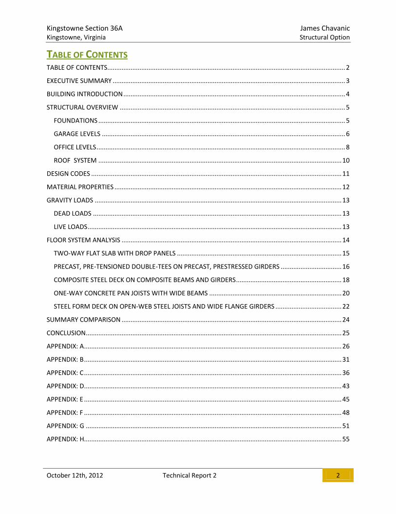
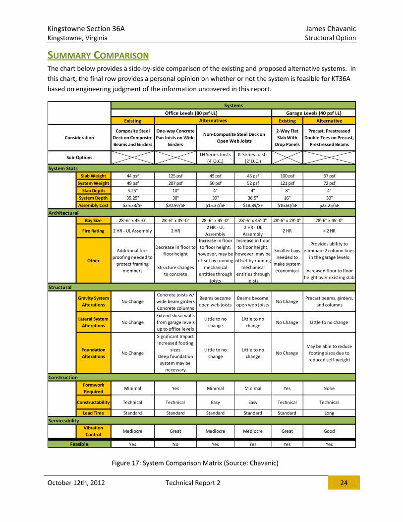
SUMMARY COMPARISON
The chart below provides a side-by-side comparison of the existing and proposed alternative systems. In
this chart, the final row provides a personal opinion on whether or not the system is feasible for KT36A
based on engineering judgment of the information uncovered in this report.
Existing Existing Alternative
Composite Steel
Deck on Composite
Beams and Girders
One-way Concrete
Pan Joists on Wide
Girders
2-Way Flat
Slab With
Drop Panels
Precast, Prestressed
Double Tees on Precast,
Prestressed Beams
LH Series Joists
(4' O.C.)
K-Series Joists
(2' O.C.)
Slab Weight 44 psf 125 psf 45 psf 45 psf 100 psf 67 psf
System Weight 49 psf 207 psf 50 psf 52 psf 121 psf 72 psf
Slab Depth 5.25" 10" 4" 4" 8" 4"
System Depth 35.25" 30" 39" 36.5" 16" 30"
Assembly Cost $25.38/SF $20.97/SF $15.32/SF $18.89/SF $16.60/SF $23.25/SF
Bay Size 28'-6" x 45'-0" 28'-6" x 45'-0" 28'-6" x 45'-0" 28'-6" x 45'-0" 28'-6" x 29'-0" 28'-6" x 45'-0"
Fire Rating 2 HR - UL Assembly 2 HR2 HR - UL
Assembly
2 HR - UL
Assembly2 HR < 2 HR
Other
Additional fire-
proofing needed to
protect framing
members
Decrease in floor to
floor height
Structure changes
to concrete
Increase in floor
to floor height,
however, may be
offset by running
mechanical
entities through
joists
Increase in floor
to floor height,
however, may be
offset by running
mechanical
entities through
joists
Smaller bays
needed to
make system
economical
Provides ability to
eliminate 2 column lines
in the garage levels
Increased floor to floor
height over existing slab
Gravity System
AlterationsNo Change
Concrete joists w/
wide beam girders
Concrete columns
Beams become
open web joists
Beams become
open web joistsNo Change
Precast beams, girders,
and columns
Lateral System
AlterationsNo Change
Extend shear walls
from garage levels
up to office levels
Little to no
change
Little to no
changeNo Change Little to no change
Foundation
AlterationsNo Change
Significant Impact
Increased footing
sizes
Deep foundation
system may be
necessary
Little to no
change
Little to no
changeNo Change
May be able to reduce
footing sizes due to
reduced self-weight
Formwork
RequiredMinimal Yes Minimal Minimal Yes None
Constructability Technical Technical Easy Easy Technical Technical
Lead Time Standard Standard Standard Standard Standard Long
Vibration
ControlMediocre Great Mediocre Mediocre Great Good
Yes No Yes Yes Yes YesFeasible
Serviceability
ConsiderationNon-Composite Steel Deck on
Open Web Joists
Sub-Options
Alternatives
Systems
Construction
Structural
Architectural
System Stats
Office Levels (80 psf LL) Garage Levels (40 psf LL)
Figure 17: System Comparison Matrix (Source: Chavanic)

Kingstowne Section 36A James Chavanic Kingstowne, Virginia Structural Option
October 12th, 2012 Technical Report 2 25
CONCLUSION
After examining Figure 17, the one-way concrete pan joist system was the only alternative considered
not feasible for Kingstowne Section 36 A. The spans lengths of 45’-0” found in the end bays are simply
too much for this floor system. The long spans yield a system that needs to be 30 inches deep in order
to satisfy ACI 318-11 Table 9.5(a). Since pan joists come in a maximum depth of 20 inches, this meant
that a 10 inch thick slab had to be chosen to get the total depth to 30 inches. This resulted in a massive
system that weighs 4 times the existing system at the office levels! If the owner permitted, bay sizes
could be adjusted making this a very plausible system. The remaining alternatives were all deemed
feasible and are worthy of being considered for further study. Of special note is the precast double tee
system which has the potential to be used in all levels of the building. This would pose an interesting
problem to solve regarding the handling of lateral loads. If the columns along grids B and E were
permitted to come up through the office levels, continuing the flat slab construction into the office
levels could become a very probable alternative.

Kingstowne Section 36A James Chavanic Kingstowne, Virginia Structural Option
October 12th, 2012 Technical Report 2 26
APPENDIX: A

Kingstowne Section 36A James Chavanic Kingstowne, Virginia Structural Option
October 12th, 2012 Technical Report 2 27

Kingstowne Section 36A James Chavanic Kingstowne, Virginia Structural Option
October 12th, 2012 Technical Report 2 28
Kingstowne Section 36A James Chavanic Kingstowne, Virginia Structural Option
October 12th, 2012 Technical Report 2 29

Kingstowne Section 36A James Chavanic Kingstowne, Virginia Structural Option
October 12th, 2012 Technical Report 2 30
Kingstowne Section 36A James Chavanic Kingstowne, Virginia Structural Option
October 12th, 2012 Technical Report 2 31
APPENDIX: B
Kingstowne Section 36A James Chavanic Kingstowne, Virginia Structural Option
October 12th, 2012 Technical Report 2 32
Kingstowne Section 36A James Chavanic Kingstowne, Virginia Structural Option
October 12th, 2012 Technical Report 2 33

Kingstowne Section 36A James Chavanic Kingstowne, Virginia Structural Option
October 12th, 2012 Technical Report 2 34

Kingstowne Section 36A James Chavanic Kingstowne, Virginia Structural Option
October 12th, 2012 Technical Report 2 35

Kingstowne Section 36A James Chavanic Kingstowne, Virginia Structural Option
October 12th, 2012 Technical Report 2 36
APPENDIX: C

Kingstowne Section 36A James Chavanic Kingstowne, Virginia Structural Option
October 12th, 2012 Technical Report 2 37
Kingstowne Section 36A James Chavanic Kingstowne, Virginia Structural Option
October 12th, 2012 Technical Report 2 38

Kingstowne Section 36A James Chavanic Kingstowne, Virginia Structural Option
October 12th, 2012 Technical Report 2 39

Kingstowne Section 36A James Chavanic Kingstowne, Virginia Structural Option
October 12th, 2012 Technical Report 2 40
Kingstowne Section 36A James Chavanic Kingstowne, Virginia Structural Option
October 12th, 2012 Technical Report 2 41

Kingstowne Section 36A James Chavanic Kingstowne, Virginia Structural Option
October 12th, 2012 Technical Report 2 42
Kingstowne Section 36A James Chavanic Kingstowne, Virginia Structural Option
October 12th, 2012 Technical Report 2 43
APPENDIX: D
Kingstowne Section 36A James Chavanic Kingstowne, Virginia Structural Option
October 12th, 2012 Technical Report 2 44

Kingstowne Section 36A James Chavanic Kingstowne, Virginia Structural Option
October 12th, 2012 Technical Report 2 45
APPENDIX: E Note: All tables and figures in this appendix were obtained from RSMeans CostWorks website.

Kingstowne Section 36A James Chavanic Kingstowne, Virginia Structural Option
October 12th, 2012 Technical Report 2 46
Kingstowne Section 36A James Chavanic Kingstowne, Virginia Structural Option
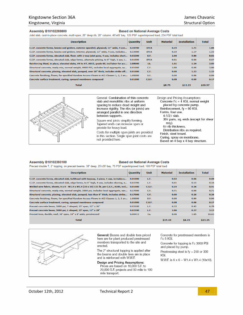
October 12th, 2012 Technical Report 2 47

Kingstowne Section 36A James Chavanic Kingstowne, Virginia Structural Option
October 12th, 2012 Technical Report 2 48
APPENDIX: F
Typical Parking Level Floor Plan
Kingstowne Section 36A James Chavanic Kingstowne, Virginia Structural Option
October 12th, 2012 Technical Report 2 49
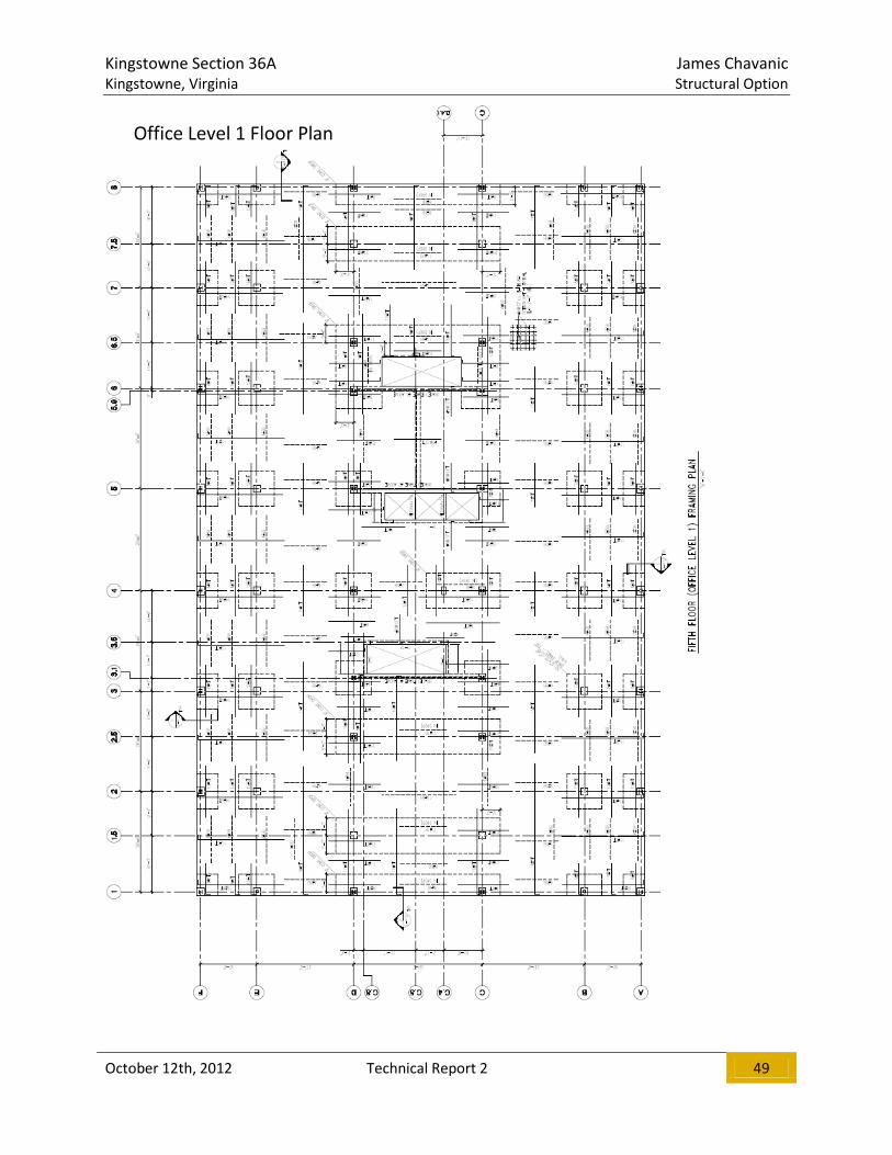
Office Level 1 Floor Plan

Kingstowne Section 36A James Chavanic Kingstowne, Virginia Structural Option
October 12th, 2012 Technical Report 2 50
Typical Office Level Floor Plan

Kingstowne Section 36A James Chavanic Kingstowne, Virginia Structural Option
October 12th, 2012 Technical Report 2 51
APPENDIX: G
Kingstowne Section 36A James Chavanic Kingstowne, Virginia Structural Option
October 12th, 2012 Technical Report 2 52

Kingstowne Section 36A James Chavanic Kingstowne, Virginia Structural Option
October 12th, 2012 Technical Report 2 53

Kingstowne Section 36A James Chavanic Kingstowne, Virginia Structural Option
October 12th, 2012 Technical Report 2 54

Kingstowne Section 36A James Chavanic Kingstowne, Virginia Structural Option
October 12th, 2012 Technical Report 2 55
APPENDIX: H

Kingstowne Section 36A James Chavanic Kingstowne, Virginia Structural Option
October 12th, 2012 Technical Report 2 56

Kingstowne Section 36A James Chavanic Kingstowne, Virginia Structural Option
October 12th, 2012 Technical Report 2 57