Technical Reference Dinverter A · Technical Reference Dinverter A A compact variable speed drive...
326
Technical Reference Dinverter A A compact variable speed drive for 3-phase induction motors 0.25kW to 0.75kW 0.33HP to 1.0HP Part No:- 0446-0008 Issue No:- 3
Transcript of Technical Reference Dinverter A · Technical Reference Dinverter A A compact variable speed drive...

Technical Reference
Dinverter A
A compact variable speed drive
for 3-phase induction motors
0.25kW to 0.75kW
0.33HP to 1.0HP
Part No:- 0446-0008
Issue No:- 3

Copyright:- February 1997
Control Techniques Drives Ltd
Issue Code:- DINA
Issue Date:- February 1997
Software Version:- V01.03.00
Editor:- MKF
Safety Information - General Overview
Variable speed drives (also referred to as drive converters or drives) and associated optionunits can be hazardous if they are not correctly installed, maintained and operated.
Persons supervising and performing the installation or maintenance of a drive and/or anyexternal option unit must be suitably qualified and competent in these duties. They shouldbe given the opportunity to study, and if necessary, to discuss the User Guide before work isstarted.
Important safety related information is given in the Sections on Mechanical Installation,Electrical Installation and Getting Started.
General Information
The manufacturer accepts no liability for any consequences resulting from negligence orincorrect installation or adjustment of the operating parameters of the equipment or frommismatching the drive with the motor.
The contents of this guide are believed to be correct at the time of printing. In the interest ofa policy of continuous development and improvement, the manufacturer reserves the right tochange the specification of the drive or its performance, or the contents of this guide withoutnotice.
All rights reserved.
No part of this guide may be reproduced or transmitted in any form or by any means,electrical or mechanical including photocopying, recording or by any information storage orretrieval system, without permission in writing from the publisher.

Warnings, Cautions and Notes
Warning, Caution and Note paragraphs appear throughout the text of this User Guide.These reminders are for the installers and operators of this equipment.
This guide contains important information affecting safety in the following sections:-
Electrical Shock Risk Section 5.1
Stored Electric Charge Section 5.1
Fire Enclosures Section 4.1
Effect on Driven Plant Section 6.1
Warning
A Warning indicates that there may be danger of loss of life or personal injury unless theinstructions are strictly observed.
Caution
A Caution indicates that there may be danger or damage to equipment if the instructions arenot strictly observed.
Note
A Note draws to the attention of the personnel using the equipment to information that willassist in their understanding of the equipment or its operation.

Safe Use of Drives
General
The instructions in this guide regarding transport, storage, installation and use of drives mustbe complied with, including the specified environmental limits. Drives must not be subjectedto excessive physical force.
The installer is responsible for complying with all relevant regulations, such as national wiringregulations and accident prevention regulations. Particular attention must be given to thecross-sectional areas of conductors, the selection of fuses or other protection, and protectiveearth (ground) connections.
Intended Use
Drives are intended as components for incorporation into electrical control systems ormachines. It is the responsibility of the installer to ensure that the drive is installed safelyand in accordance with any regulations which apply to the end product at the place of use, forexample regarding safety or electro-magnetic compatibility.
To ensure mechanical safety, additional safety devices such as electro-mechanical interlocksmay be required.
This guide contains instructions for achieving compliance with specific EMC(Electromagnetic Compatibility) standards.
Use within the European Union etc.
The following information applies where the end use of the drive is within the EuropeanUnion, the European Economic Area, or other regions which have implemented theEuropean Council Directives or equivalent measures.
The drive complies with the Low Voltage Directive 73/23/EEC.
The installer is responsible for ensuring that the equipment into which the drive isincorporated complies with all relevant Directives.
The complete equipment must comply with the EMC Directive 89/336/EEC. Section 5.4describes how the drive must be installed to ensure that it meets relevant EMC standards.
If the drive is incorporated into a machine, the manufacturer is responsible for ensuring thatthe machine complies with the Machinery Directive 89/392/EEC. In particular, the electricalequipment should generally comply with European Harmonised standard EN60204-1.
__________
Contents
1.0 Using this Guide 1-1
2.0 Drive Description 2-1
2.1 Basic Information 2-1
2.2 Features 2-2
2.3 Block Diagram 2-4
3.0 Drive and Options - Data and Specification 3-1
3.1 Drive Rating Label 3-1
3.2 Drive Power Stage Data 3-2
3.3 Drive Environmental Data 3-6
3.4 Drive Weights and Dimensions 3-7
3.5 Drive Control Data 3-7
3.6 Drive Electrical Protection Data 3-13
3.6.1 Power Stage Protection Limits 3-14
3.6.2 Motor Protection 3-14
3.7 Option Data 3-15
3.7.1 RFI Filter Data 3-15
3.7.1.1 Rating Label 3-17
3.7.1.2 Power Data 3-18
3.7.1.3 Environmental Data 3-19
3.7.1.4 Weights and Dimensions 3-19
3.7.1.5 EMC Specifications 3-19
3.7.1.6 Filter Protection Limits 3-20
3.7.2 Braking Resistor Data 3-21

4.0 Mechanical Installation 4-1
4.1 Warnings 4-1
4.2 Parts Supplied with Drive 4-2
4.2.1 Parts Supplied with the Optional RFI Filter1 4-3
4.3 Storage and Transportation 4-5
4.3.1 Storage 4-5
4.3.2 Transportation 4-6
4.4 Planning the Installation 4-6
4.5 Mounting the Drive 4-8
4.5.1 DIN Rail Mounting 4-10
4.5.2 Panel Mounting 4-13
4.5.3 Mounting the Optional RFI Filter 4-15
4.5.4 Mounting the Optional Braking Resistor 4-16
4.6 Cabling the Drive 4-17
4.6.1 Access to the Drive Terminal Chamber 4-17
4.6.2 Gland Plate 4-18
4.6.3 Cabling Notes 4-20
4.6.4 Cabling the Optional RFI Filter 4-21
4.6.5 Cabling the Optional Braking Resistor 4-23
4.7 Enclosure Heat Dissipation Calculations 4-23
4.7.1 Sealed Enclosures 4-23
4.7.2 Ventilated Enclosures 4-24

5.0 Electrical Installation 5-1
5.1 Warnings 5-1
5.2 Overview and Notes 5-2
5.2.1 Access to Electrical Connections 5-2
5.2.2 Earthing/Ground Connections 5-2
5.2.3 AC Supplies 5-3
5.2.4 EMC Wiring Layout Recommendations 5-3
5.2.5 Fuses and Cable Sizes 5-3
5.2.6 Cable Lengths 5-5
5.2.7 Matching Motor(s) to the Drive 5-5
5.2.8 Multi-Motor Arrangements 5-6
5.2.9 Switching the Motor to the Drive 5-6
5.3 Power Connections 5-7
5.3.1 AC Supply Connections 5-7
5.3.2 Motor Connections 5-8
5.3.3 Optional RFI Filter Connections 5-8
5.3.4 Optional Braking Resistor Connections 5-11
5.3.4.1 Braking Resistor Sizing - Essential Requirements 5-12
5.3.4.2 Braking Resistor Sizing - Optimisation 5-13
5.4 EMC Considerations 5-16
5.4.1 General Principles 5-16
5.4.2 Routine EMC Precautions 5-17
5.4.3 Compliance with EMC Emission Standards 5-19
5.4.3.1 Interruptions to the Motor Cable 5-21
5.4.3.2 Braking Resistor Wiring Externalto the Drive Enclosure 5-23
5.5 Control Connections 5-24
5.5.1 Positive/Negative Digital Input Logic 5-24
5.5.2 Control Terminal Block ‘A1’ to ‘A5’ 5-25
5.5.3 Control Terminal Block ‘B1’ to ‘B5’ 5-28
5.5.4 Control Terminal Block ‘C1’ to ‘C5’ 5-31
5.5.4.1 Terminal Chamber Resistor -C4/C5 Terminating Resistor 5-34

6.0 Operation of Display, Keypad and Parameters 6-1
6.1 Warnings 6-1
6.2 Initial Electrical and Mechanical Set-Up 6-2
6.3 User Interface (Display and Keypad) 6-4
6.3.1 LED Display 6-4
6.3.2 Keypad 6-6
6.4 Parameter Structure 6-7
6.4.1 Types of Parameter 6-7
6.4.2 Organisation of Parameters 6-8
6.4.3 “Parameter 0” 6-9
6.4.4 Parameter Location - Menus 6-10
6.5 Selecting, Viewing and Changing Parameters 6-10
6.5.1 LED Display Modes 6-10
6.5.2 Selecting a Parameter Within a Menu 6-11
6.5.3 Viewing and Changing the Selected Parameter 6-13
6.5.4 Changing Menus 6-15
6.6 Storing/Restoring Parameters 6-16
6.6.1 Storing/Saving and Restoring Parameters 6-16
6.6.2 Resetting the Drive 6-16
6.6.3 Setting Parameters to Default Values 6-17
6.7 Parameter Security 6-18
7.0 Menu 0 Parameter Descriptions 7-1
7.1 General 7-1
7.2 Menu 0 logic block diagram - Default settings 7-2
7.3 Menu 0 Parameter List 7-3
7.4 Menu 0 Parameter Descriptions 7-9
8.0 Commissioning - Getting Started 8-1
8.1 Warnings 8-1
8.2Initial Electrical and Mechanical Set-Up 8-2
8.3Configuring Drive for Connected Motor(s) 8-4
8.4Operating Drive Using Control Terminal Inputs 8-6
8.5Operating the Drive Using the Keypad 8-8

9.0 Extended Menus (1 through to 9, A, b, c, E) Parameter Descriptions 9-1
9.1 General 9-1
9.2 Menu 1 logic block diagram -Frequency reference selection, limits and filters 9-4
9.2.1 Menu 1 Parameter List 9-5
9.2.2 Menu 1 Parameter Descriptions 9-7
9.3 Menu 2 logic block diagram - Ramps 9-21
9.3.1 Menu 2 Parameter List 9-23
9.3.2 Menu 2 Parameter Descriptions 9-25
9.4 Menu 3 logic block diagram - Frequency/speed sensing thresholds 9-34
9.4.1 Menu 3 Parameter List 9-34
9.4.2 Menu 3 Parameter Descriptions 9-34
9.5 Menu 4 logic block diagram - Current control 9-36
9.5.1 Menu 4 Parameter List 9-37
9.5.2 Menu 4 Parameter Descriptions 9-38
9.6 Menu 5 logic block diagram - Machine control 9-49
9.6.1 Menu 5 Parameter List 9-50
9.6.2 Menu 5 Parameter Descriptions 9-51
9.7 Menu 6 logic block diagram - Drive sequencer and run-time clock 9-63
9.7.1 Menu 6 Parameter List 9-64
9.7.2 Menu 6 Parameter Descriptions 9-65
9.8 Menu 7 logic block diagram - Analogue inputs and outputs 9-79
9.8.1 Menu 7 Parameter List 9-80
9.8.2 Menu 7 Parameter Descriptions 9-81
9.9 Menu 8 logic block diagram - Digital inputs and outputs 9-90
9.9.1 Menu 8 Parameter List 9-91
9.9.2 Menu 8 Parameter Descriptions 9-92
9.10 Menu 9 logic block diagram -Programmable logic and motorised potentiometer 9-98
9.10.1 Menu 9 Parameter List 9-99
9.10.2 Menu 9 Parameter Descriptions 9-100
9.11 Menu A logic block diagram - Status logic and diagnostics 9-106
9.11.1 Menu A Parameter List 9-106
9.11.2 Menu A Parameter Descriptions 9-108
9.12 Menu b - Miscellaneous and Menu 0 parameter selectors 9-122
9.12.1 Menu b Parameter List 9-122
9.12.2 Menu b Parameter Descriptions 9-123
9.13 Menu c logic block diagram - Programmable threshold 9-129
9.13.1 Menu c Parameter List 9-129
9.13.2 Menu c Parameter Descriptions 9-130
9.14 Menu E logic block diagram - PID controller 9-133
9.14.1 Menu E Parameter List 9-133
9.14.2 Menu E Parameter Descriptions 9-134
10.0 Diagnostics/Fault Indications 10-1
10.1 Normal Status Display Indicators 10-1
10.2 Warning Display Indicators 10-2
10.3 Trip Display Indicators 10-2
11.0 Serial Communications 11-1
11.1 Introduction 11-1
11.2 Initial Electrical and Mechanical Set-Up 11-2
11.3 Relevant Parameters 11-4
11.4 ANSI Protocol Description 11-6
11.4.1 Reading Data 11-9
11.4.2 Writing Data 11-13
_________
1-1
1.0 Using this Guide
Reading through the sections in numerical order will take you through the correct stages thatare needed to install and operate the drive. In particular:-
• Section 2.0 gives an overview of the drive and its features.
• Section 3.0 gives a complete set of data/specification details for the drive and options.
• Section 4.0 details how to mechanically install the drive and options.
• Section 5.0 gives electrical installation details.
• Section 6.0 gives details concerning the operation of the LED/keypad of the drive toadjust drive parameters.
• Section 7.0 gives details about the Menu 0 parameters that enable the drive to be set-upfor the majority of applications.
• Section 8.0 gives brief details as to how to operate the drive with a minimum amount ofset-up.
• Section 9.0 gives advanced operating details available through the standard extendedmenus and parameters
• Section 10.0 gives diagnostic and fault indication details.
• Section 11.0 gives details about using serial communications.
• Section 12.0 provides examples of typical application examples using the drive.
• Section 13.0 provides you a comment/response sheet for your feedback and opinionsabout the drive and this manual for future drive improvements .
It is important that the basic installation and operating procedures have been carried outcorrectly before attempting to use any of the extended menu operating features detailed inSection 9.0 onwards.
All safety information relates to the drive itself and the drive with the RFI (Radio FrequencyInterference) filter option.
__________

1-2
2-1
2.0 Drive Description
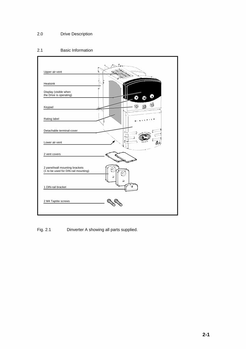
2.1 Basic Information
Upper air-vent
Heatsink
Display (visible when the Drive is operating)
Keypad
Rating label
Detachable terminal-cover
Lower air-vent
2 vent covers
2 panel/wall mounting brackets(1 to be used for DIN-rail mounting)
1 DIN-rail bracket
2 M4 Taptite screws
Fig. 2.1 Dinverter A showing all parts supplied.

2-2
The Dinverter A is one drive size in a family of Dinverter drives designed to operate asvariable speed electronic drives for squirrel cage induction motors (or synchronous motors).
The Dinverter requires a 200 to 240V (line to line or line to neutral) 50 to 60Hz supply todrive three phase motors with a total output power of up to 0.75kW (1.0HP).
The speed of the motor is controlled by the drive which has a user interface consisting of adisplay and keypad, digital/analogue inputs and outputs, and a serial communicationsinterface. The drive user can control the motor speed by using any of the user interfaces.
The Dinverter is fully digital (microprocessor controlled) and uses the latest power electronicdevices to digitally control the flow of electrical power between the incoming AC supply andthe driven motor.
The Dinverter is designed to be either panel mounted or DIN rail mounted using the bracketssupplied.
2.2 Features
The main features are:
• Single phase (line to neutral) or two phase (line to line) 200 - 240VAC supply requirement
• Motor powers up to 0.75kW (1.0HP)
• UL listed
• IP20 with vent covers removed.
Ingressprotection
Gland plate not fitted: IP00
Gland plate fitted; cable glands not fitted: IP10
Cable-glands fitted; vent covers not fitted: IP20
Cable-glands fitted; vent covers fitted: IP20, NEMA 1
• NEMA 1 with upper vent cover fitted
• DIN rail or panel/wall mounting
• In-built braking (requires an external braking resistor)
• Full digital control
• 150% overload for 60 seconds
• Motor speed capability up to 960Hz
• Drive inverter switching frequency up to 12kHz for quiet motor operation
• High impedance isolation between power circuit and control connections so that thecontrol interface is not directly linked to the power circuit
2-3
Control features include:
• Programmable motor voltages and frequencies
• Standard 2-wire RS485 serial communications
• Standard display and 6 button keypad for drive set-up/diagnostics
• Set up includes ramp rates, preset speeds, skip frequencies, auto reset etc.
• Flexible and programmable digital/analogue inputs and outputs
• 1 Volt-free 2A 250VAC contact
• 1 Differential analogue current input (configurable as 0 to 20mA, 4 to 20mA, 20 to0mA, 20 to 4mA or motor thermistor input).
• 1 Analogue voltage input (configurable as -10V to +10V, or motor thermistorinput)
• 1 Analogue output (0-20mA or 0-10V)
• 5 Digital inputs (2 configurable as digital outputs) with positive and negative logiccapability
2-4
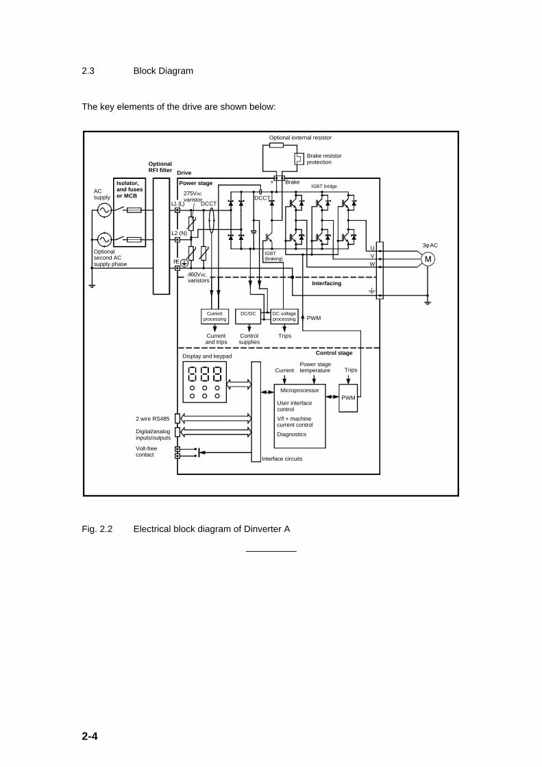
2.3 Block Diagram
The key elements of the drive are shown below:
DC/DC
275VAC
varistor
Current processing
DC voltage processing
PWM
2 wire RS485
Digital/analoginputs/outputs
Optional RFI filter
AC supply
Isolator, and fuses or MCB
Optional second AC supply phase
DCCT
Power stage
Microprocessor
User interface control
V/f + machine current control
Diagnostics
Power stage temperatureCurrent Trips
Interface circuits
Display and keypad
Volt-free contact
PWM
UVW
IGBT (braking)
Optional external resistor
Brake resistor protection
Brake+
Control stage
Current and trips
Control supplies
Trips
3φ AC
DCCTL1 (L)
L2 (N)
PE
IGBT bridge
Drive
460VAC
varistors Interfacing
Fig. 2.2 Electrical block diagram of Dinverter A
__________
3-1
3.0 Drive and Options - Data and Specification
3.1 Drive Rating Label
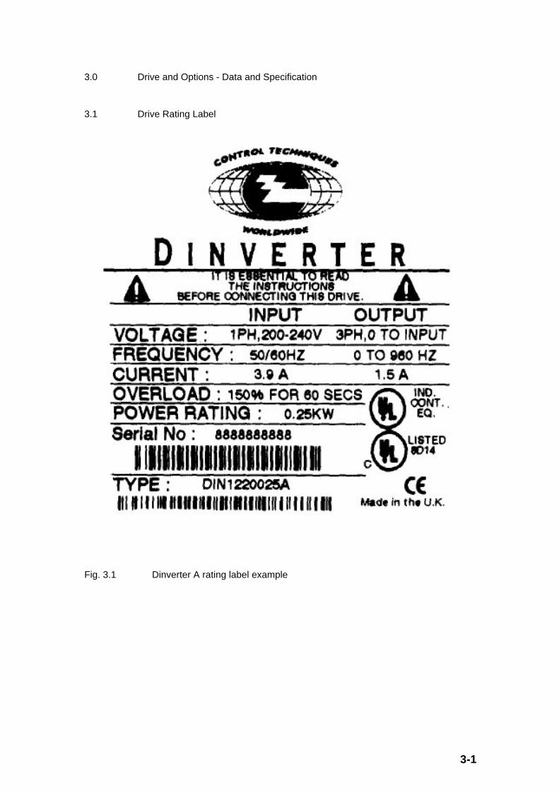
Fig. 3.1 Dinverter A rating label example
3-2
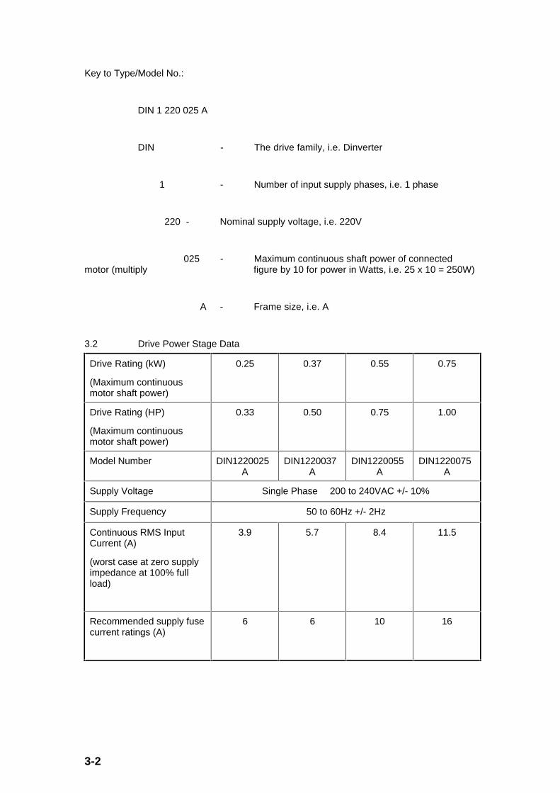
Key to Type/Model No.:
DIN 1 220 025 A
DIN - The drive family, i.e. Dinverter
1 - Number of input supply phases, i.e. 1 phase
220 - Nominal supply voltage, i.e. 220V
025 - Maximum continuous shaft power of connectedmotor (multiply figure by 10 for power in Watts, i.e. 25 x 10 = 250W)
A - Frame size, i.e. A
3.2 Drive Power Stage Data
Drive Rating (kW)
(Maximum continuousmotor shaft power)
0.25 0.37 0.55 0.75
Drive Rating (HP)
(Maximum continuousmotor shaft power)
0.33 0.50 0.75 1.00
Model Number DIN1220025A
DIN1220037A
DIN1220055A
DIN1220075A
Supply Voltage Single Phase 200 to 240VAC +/- 10%
Supply Frequency 50 to 60Hz +/- 2Hz
Continuous RMS InputCurrent (A)
(worst case at zero supplyimpedance at 100% fullload)
3.9 5.7 8.4 11.5
Recommended supply fusecurrent ratings (A)
6 6 10 16

3-3
UL tested fuse (fast actingtype)
Bussmann Limitron KTK-15A
(600VAC 100kA breakingcapacity
10.3 x 38 mm Midget Fuse)
15 15 15 15
Continuous RMS OutputCurrent (A)
(at 100% full load)
Note: * - Refer to de-ratingcurves given in Figs 3.2and 3.3 below.
1.5 2.3 3.0* 4.3*
Overload (150%) RMSOutput Current for 60seconds (A)
2.3 3.5 4.5 6.5
Output Voltage (Line toLine)
0 to Supply Voltage
Output Frequency 0 to 960Hz
Output SwitchingFrequencies*
Note: * - Refer to de-ratingcurves given in Figs 3.2and 3.3 below.
3, 6, 9 and 12kHz
Maximum power losses (asheat) (W)
at 3kHz switchingfrequency
17.3 22.1 26.1 39.9
Maximum power losses (asheat) (W)
at 6kHz switchingfrequency
19.1 24.4 29.3 45.7

3-4
Maximum power losses (asheat) (W)
at 9kHz switchingfrequency
19.9 27.1 34.5 50.9
Maximum power losses (asheat) (W)
at 12kHz switchingfrequency
21.3 29.9 38.3 55.9
Power up surge (worst casepeak value)
Repetition rate - unlimited
(a half sinewave currentpulse of a quarter supplycycle duration) (A)
- 50Hz Supply
55 55 110 110
Power up surge (worst casepeak value)
Repetition rate - unlimited
(a half sinewave currentpulse of a quarter supplycycle duration) (A)
- 60Hz Supply
66 66 130 130
Motor starts per hour Limited by motor only
In-built DC bus DischargeResistor
Will discharge DC bus voltage to less than 50VDC within amaximum 8 minute period after removing the AC supply,independently of whether the drive is functioning. (Undercertain unusual circumstances the drive can be energised
from the motor connections.)
3-5
50
45
40
35
30
25
20
122
113
104
95
86
77
68
°C °F
0.5 1.0 1.5 2.0 2.5 3.0 3.5 4.0 4.50
No deratingDIN1220025A
No derating DIN1220037A
4.3A
22°C72°F
26°C79°F
30°C86°F
40°C104°F
12kHz
9kHz
6kHz
3kHz
Motor current (A)
Ambient temperature
3.0A
Derate 12kHzDIN1220055A
1.5A 2.3A 3.6A 3.7A
2.85A
Derate all DIN1220075A
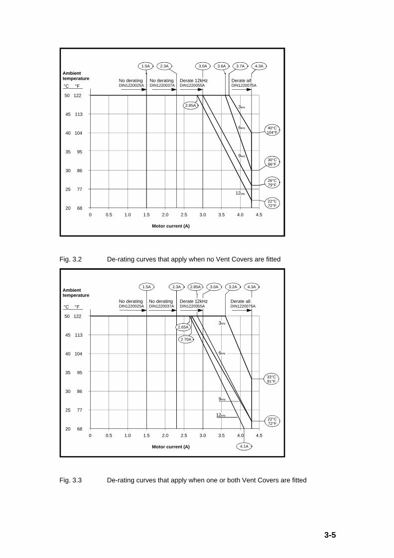
Fig. 3.2 De-rating curves that apply when no Vent Covers are fitted
50
45
40
35
30
25
20
122
113
104
95
86
77
68
°C °F
0.5 1.0 1.5 2.0 2.5 3.0 3.5 4.0 4.50
No deratingDIN1220025A
No derating DIN1220037A
4.3A
Motor current (A)
Ambient temperature
3.0A
Derate 12kHzDIN1220055A
1.5A 2.3A 2.85A
4.1A
3.2A
22°C72°F
33°C91°F
3kHz
6kHz
9kHz
12kHz
2.70A
2.65A
Derate all DIN1220075A
Fig. 3.3 De-rating curves that apply when one or both Vent Covers are fitted
3-6
As an example to aid using the above diagrams, consider the requirement of a drive needingto run a motor with a current requirement of 3.5A in a 40oC ambient.
Firstly this current requirement is only available with the 0.75kW (1.0HP) unit.
If the Vent Covers are not fitted, Fig. 3.2 indicates that the drive will operate withinspecification at 9kHz, 6kHz or 3kHz but not 12kHz. (At 12kHz the maximum allowableambient is about 38oC at 3.5A, or at 40oC ambient the allowable current is 3.4A).
If the Vent Covers are fitted, Fig. 3.3 indicates that the drive will operate within specificationat 6kHz or 3kHz but not at 9 or 12kHz. (At 12kHz the maximum allowable ambient is about32oC at 3.5A, or at 40oC ambient the allowable current is 3.1A. Similarly, at 9kHz themaximum allowable ambient is about 36 oC at 3.5A, or at 40oC ambient the allowable currentis 3.3A.)
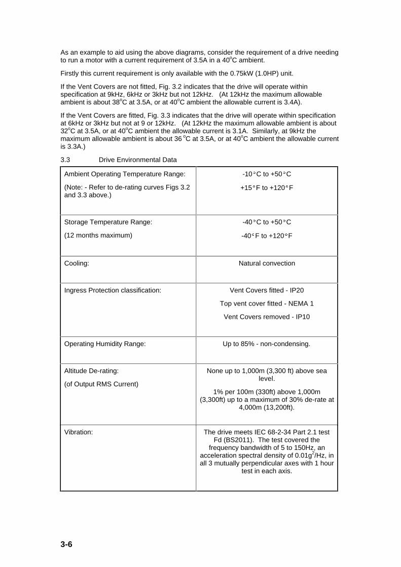
3.3 Drive Environmental Data
Ambient Operating Temperature Range:
(Note: - Refer to de-rating curves Figs 3.2and 3.3 above.)
-10§C to +50§C
+15§F to +120§F
Storage Temperature Range:
(12 months maximum)
-40§C to +50§C
-40§F to +120§F
Cooling: Natural convection
Ingress Protection classification: Vent Covers fitted - IP20
Top vent cover fitted - NEMA 1
Vent Covers removed - IP10
Operating Humidity Range: Up to 85% - non-condensing.
Altitude De-rating:
(of Output RMS Current)
None up to 1,000m (3,300 ft) above sealevel.
1% per 100m (330ft) above 1,000m(3,300ft) up to a maximum of 30% de-rate at
4,000m (13,200ft).
Vibration: The drive meets IEC 68-2-34 Part 2.1 testFd (BS2011). The test covered the
frequency bandwidth of 5 to 150Hz, anacceleration spectral density of 0.01g2/Hz, inall 3 mutually perpendicular axes with 1 hour
test in each axis.

3-7
3.4 Drive Weights and Dimensions
Weight: DIN1220025A ) 1.14 kg
DIN1220037A ) 2.51 lbs
DIN1220055A ) 1.21 kg
DIN1220075A ) 2.67 lbs
Dimensions: Height: 140mm (5.5”)
Width: 75mm (3.0”)
Depth: 192mm (7.5”)
3.5 Drive Control Data
Internal output frequency accuracy: ñ 0.01%
Internal output frequency resolution: 0.001Hz up to 480Hz
0.002Hz up to 960Hz
Internal output voltage accuracy: Depends on supply stability
Internal output voltage resolution: 0.4%
Internal current/load accuracy: ñ10% above 20Hz with a matched motor.
Internal current/load resolution: 0.1%
Internal current limit/torque control: Sampled every 2ms
3-8
0V Common (Terminals A1, B1 and C1)
• Quantity per drive - 3
• Isolated by 3.3MΩ to power circuit and basic insulation.
• Capable of withstanding 2.0kVAC between power connections and control connectionscontinuously.
• Drive will operate with no adverse effects with the 0V Common at a potential difference ofup to 90VAC (at the AC supply frequency) from either input of the AC supply
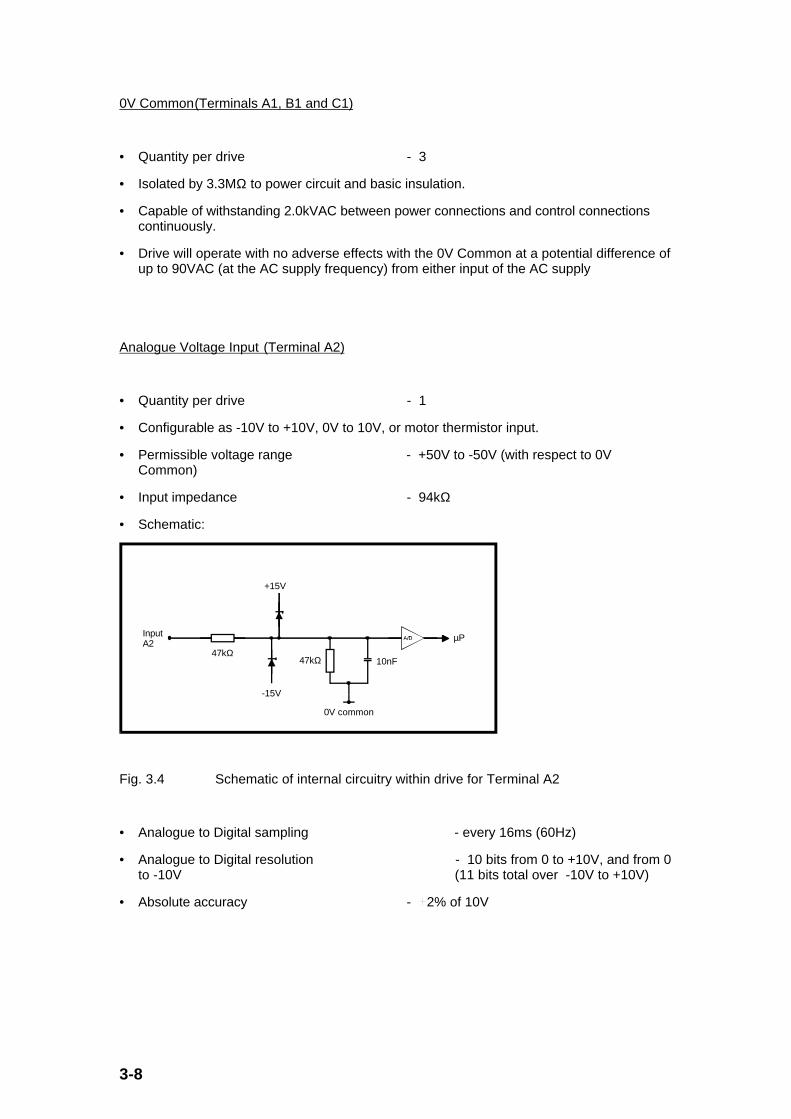
Analogue Voltage Input (Terminal A2)
• Quantity per drive - 1
• Configurable as -10V to +10V, 0V to 10V, or motor thermistor input.
• Permissible voltage range - +50V to -50V (with respect to 0VCommon)
• Input impedance - 94kΩ
• Schematic:
InputA2
47kΩ47kΩ
0V common
-15V
+15V
10nF
µP
Fig. 3.4 Schematic of internal circuitry within drive for Terminal A2
• Analogue to Digital sampling - every 16ms (60Hz)
• Analogue to Digital resolution - 10 bits from 0 to +10V, and from 0to -10V (11 bits total over -10V to +10V)
• Absolute accuracy - ñ2% of 10V

3-9
Differential Analogue Current Input or RS485 Input (Terminals C4 and C5)
• Quantity per drive - 1
• Configurable as 0 to 20mA, 4 to 20mA, 20 to 0mA, 20 to 4mA or motor thermistor input.
• Permissible voltage range - -7V to +12V (on each input with respect to0V Common)
• Input impedance - 100Ω (C4/C5 terminating resistor accessible in terminal chamber)
• Operating Common Mode Voltage Range: - -5V to +10V (with respect to 0V Common)
• RS485 Protocol - ANSI x3.28 - 2.5 A4 at 4800 baud only
• Schematic:
Inputs
C5
C4
C4 / C5 minating C4 / C5
100R 1% 0.5W
12kΩ
12kΩ
0V common
RS485 transceiver
A/D
x2.5µP µP_A
A
Fig. 3.5 Schematic of internal circuitry within drive for Terminals C4 and C5
• Analogue to Digital sampling - every 16ms (60Hz)
• Analogue to Digital resolution - 10 bits (over 0 to 20mA input)
• Absolute accuracy - ñ3% of 20mA
Analogue Output (Terminal C2)
• Quantity per drive - 1
• Configurable as 0 to 20mA, 4 to 20mA, or 0 to 10V
• Permissible voltage (applied to output) - 0V to +15V (with respect to 0VCommon)
• Output can tolerate a short-circuit to 0V Common continuously
• Schematic:

3-10
OutputC2
0V common
47kΩ
Select current (0 - 20mA) or voltage (0 - 10V)
+15VµP
µP
100R 1%
Fig. 3.6 Schematic of internal circuitry within drive for Terminal C2
• Digital to Analogue update - every 32ms (30Hz)
• Digital to Analogue resolution - 10 bits (over 0 to 20mA or 0 to+10V)
• Absolute accuracy - ñ5% of 10V or 20mA
• 0 to +10V output source capability - 5mA minimum.
• 0 to 20mA output voltage capability - 0 to +10V minimum range.
+10V Reference Output (Terminal A3)
• Quantity per drive - 1
• Output can tolerate a short-circuit to 0V Common continuously.
• Absolute accuracy - ñ3%
• Source capability - 5mA minimum.
Volt-Free Normally open (N/O) Contact (Terminals A4 and A5)
• Quantity per drive - 1
• Contact switching capability - 2A (resistive) at 250VAC or 24VDC
• Contact resistance - maximum of 100mΩ
• Contact controlled by microprocessor update rate - every 8ms (120Hz)
• Contact (open) withstand capability - 750VAC
• Contact isolation to all other circuitry - 2.5kVAC (meets IEC664-1 with overvoltage category III)

3-11
Digital Inputs (0 to +24V) (Terminals B2, B3 and B4)
• Quantity per drive - 3
• Permissible voltage - -3V to +30V (with respect to 0V Common)
• Schematic:
Negativelogic
Positivelogic
InputB2 B3 B4
0V common
6kΩ68kΩ
15kΩ 47nF
+15V
0V
µP
Fig. 3.7 Schematic of internal circuitry for within drive Terminals B2, B3 and B4
• Digital sampling - every 8ms
• Negative logic (Volt-free input) - inactive high ò 11.1V or ò 21.2kΩ
- active low ó 4.4V or ó 2.6 kΩ
(all referenced to 0V Common)
• Positive logic (Active input) - active high ò 11.1V
- inactive low ó 4.4V
- input impedance 5.6kΩ to 0V
(all referenced to 0V Common).
Digital Input/Outputs (0 to +24V) with Relay Drive Capability (Terminals B5 and C3)
• Quantity per drive - 2
• Permissible voltage - -3V to + 30V (with respect to 0V Common)
• Relay Driver output has a current foldback protection circuit that ensures the output will shut-down and protect if overloaded, or connected to any voltage over the
permissible range
• Schematic:

3-12
Current foldback protection
Negativelogic
Positivelogic
InputB5C3
Digital output control
0V common
0V common
6kΩ
6.8Ω
68kΩ
15kΩ 47nF
+15V
0V
µP
µP33V
3.3V
Fig. 3.8 Schematic of internal circuitry within drive for Terminals B5 and C3
• Digital sampling of input - every 8ms
• Digital update of output - every 8ms
• Negative logic (Volt-free input) - inactive high ò 11.1V or ò 21.2kΩ
- active low ó 4.4V or ó 2.6 kΩ
(all referenced to 0V Common)
• Positive logic (Active input) - active high ò 11.1V
- inactive low ó 4.4V
- input impedance 5.6kΩ to 0V
(all referenced to 0V Common).
• Digital output sinking capability - 50mA minimum with an output voltageless than 1V
• Digital output goes high impedance when current foldback protection operates. (Reset by removing overload and resetting the drive)
• Digital output sourcing capability (when input configured as negative logic)
- an internal 5.6kΩ in series with 14.0V to0V Common (i.e. 2.5mA when shorted to
0V Common)

3-13
3.6 Drive Electrical Protection Data
The Dinverter is internally protected against external influences outside the specified workingranges. This protection is designed to prevent internal damage. However, if certain limitsare exceeded the drive will fail (see Section 3.6.1 below). The drive is also protectedagainst internal malfunctions.
The drive has the following shutdown faults: (See Section 10.3 for details concerning howthese faults are indicated and simple measures to avoid their occurrence).
• Overvoltage in the DC link circuit caused by excessive deceleration or machine braking
• Undervoltage in the DC link circuit caused by loss of or low AC supply
• Short circuit or earth/ground fault at the inverter output.
• Short circuit at the brake output.
• Overheating of the power stage.
• Overheating at the motor (using the motor thermistor input capability or the Ixt facility)
• External trip/fault input.
• Low current input (open circuit or < 3.0mA) on 4-20mA analogue input.
• Internal power supplies outside specification.
• Overspeed during high levels of regeneration.
• Errors in stored parameter data during software verification.
• Keypad pushbutton depressed at power-up.
• Software not functioning correctly during operation caused by external electrical noisecorrupting the microprocessor program
• Microprocessor oscillator faulty during operation.
• Current measuring offset too high at power-up.
The above faults are: readable on the drive display,
or accessible via serial communications,
or can appear as a logic state change at the digital outputsor the volt-free relay contact.

3-14
3.6.1 Power Stage Protection Limits
• DC Bus Overvoltage Trip level - 405VDC (+/-3%)
(Above which the DC bus capacitors are liable to fail, followed by the main power devices.)
• DC Bus Undervoltage Trip level - 159VDC (+/-3%)
(Below which the switch mode supply cannot produce an orderly shut-down of the microprocessor software and save the relevant drive parameters.)
• AC Supply overvoltage capability - 275VAC.
(Above this level the protection varistor (MOV) will destructively fail and the braking IGBT will be “on” continuously.)
• Transient overvoltage protection - 4kV (IEEE/ANSI 1.2/50 µs surge i.e. 1.2µs rise time, 50µs duration).
(between any input line to earth/ground and between input lines.)
(The varistors (MOVs) have an energy absorption capability of 63J (between line to line) and 135J (between line to earth/ground to tolerate these impulses.)
• Instantaneous Output Current Trip level
- 14A (+/-5%) (DIN1220055A and DIN1220075A)
- 7A (+/-5%) (DIN1220025A and DIN1220037A)
(The drive will trip under the following faults
- Output Phase to Output Phase Short Circuit,
- Output Phase to Earth/Ground Short Circuit,
- Output Brake to +DC Short Circuit)
• Overheating Trip Temperature of the power stage -100oC (+/-2oC) (212oF(+/-4oF)
3.6.2 Motor Protection
The drive includes a thermal model to give protection for the motor (see Section 9.5). Inaddition there is the capability of using motor thermistors to detect excessive motortemperature (see Section 5.5).

3-15
3.7 Option Data
The Dinverter drive has two options available:
• The DIN1012F RFI (Radio Frequency Interference) Filter
• Braking Resistor with the necessary thermal overload
All other features are built into the drive as standard.
The DIN1012F RFI filter is required if the drive installation needs to meet the CENELEC(European) or other EMC (Electromagnetic Compatibility) conducted emission standards.
A braking resistor is required for applications where regeneration occurs (i.e. power flowsfrom the motor shaft into the motor and then into the drive) and is at such a level thatinherent losses in the drive system cannot dissipate the power (excess regeneration willcause an overvoltage trip in the drive). Regeneration is caused by mechanical loadsoverhauling the motor shaft, and is also typically caused when the drive decelerates. Therate of deceleration and motor inertia determines whether a braking resistor is needed.
3.7.1 RFI Filter Data
Rating label
Detachable terminal-cover
2 panel/wall mounting brackets (1 to be used for DIN-rail mounting)
2 M4 Taptite screws
Template / quick-reference card
1 DIN-rail bracket

3-16
Fig. 3.9 Dinverter A RFI Filter showing all parts supplied
AC supply
Isolator, and fuses or MCB
Optional second AC supply phase
L1 (L)
L2 (N)
PE
460VAC
L1′
L2′
E′
D1 D2
L1 (L)
L2 (N)
PE
L1′
L2′
E′
L1 (L)
L2 (N)
PE
RFI filter Drive
Link for long cables from Drive to motor
460VAC
Fig. 3.10 Electrical block diagram of Dinverter A RFI Filter and Drive
The RFI (Radio Frequency Interference) filter Model No. DIN1012F is suitable for allDinverter Size A models. The filter can be configured in two ways depending on the motorcable length (see Section 3.7.1.5). The specification of the RFI filter matches the Dinverterdrive but has the following major differences as detailed below in the sub-sections.

3-17
3.7.1.1 Rating Label
Fig. 3.11 Dinverter A RFI Filter rating label example

3-18
3.7.1.2 Power Data
As for the drive except the following:
• Power terminal block is pluggable for ease of cabling.
• Rated 100% Continuous Current - 12ARMS
• Maximum Power losses: (W) - 8W
(for all drive switching frequencies)
• Maximum Earth/Ground Leakage Current (configured in Standard Mode - D1 and D2 notlinked)
- 2.7mA (at 240V 50Hz)
- 3.0mA (at 220V 60Hz)
(Above figures can be directly scaled for other voltages and frequencies.)
Example : leakage current at 230V, 60Hz = 2.7×(230/240)×(60/50) = 3.11mA
• Maximum Earth/Ground Leakage Current (configured in Long Cable Mode - D1 and D2linked)
- 52.5mA (at 240V 50Hz)
- 57.7mA (at 220V 60Hz)
(Above figures can be directly scaled for other voltages and frequencies asillustrated above.)
• Voltage drop at rated current < 1V
• No de-ratings needed for any ambient temperature up to 40§C (104§F). De-rate by0.2A/§C (0.11A/§F ) to 50§C (122§F). Note that due to the impedance of the filter thedrive input current is reduced. Therefore in practice, this de-rating is not needed withDinverter A.
3-19
3.7.1.3 Environmental Data
As for the drive except the following:
Ambient Operating Temperature Range:
(Note: - Refer to de-rating information inSection 3.7.1.2 above.)
-10§C to +50§C
+15§F to +120§F
.
3.7.1.4 Weights and Dimensions
• Weight: 0.65 kg (1.4lbs)
• Dimensions: Height 140mm (5.5”)
Width 40mm (1.6”)
Depth 192mm (7.5”)
3.7.1.5 EMC Specifications
The Dinverter RFI Filter has been designed for optimum performance with the 0.25-0.75kWrange of Dinverter Size A drives. The filter will permit the drive to comply with the conductedemission requirements of the CENELEC generic emission standards:
EN50081-1 Residential environment
EN50081-2 Industrial environment
The filter has two modes of operation
a.) Standard mode
The filter can operate in its standard mode for most applications in which the motorcable length does not exceed 20m (66ft). In such applications the earth leakage currentis less than 3.5mA complying with most safety standards. This mode is achieved by notconnecting D1 and D2.
b.) Long cable mode
The filter has an optional link to increase the filter performance for long motor cable andhigh switching frequency applications. This is achieved by connecting D1 to D2. This willincrease the earth leakage current. In this mode it is essential that a permanent secureearth connection is made.

3-20
The following table specifies the filter performance with respect to motor cable length anddrive switching frequency. The table also specifies the required modes of operation.
Motor cable Drive switching frequency
length 3kHz 6kHz 9kHz 12kHz
1m (3ft) R R R R
5m (16ft) R R R R
10m (33ft) R R R R
15m (49ft) R R* R* I*
20m (66ft) R R* I* I*
30m (99ft) R* I* I* I*
50m (165ft) R* I* I* I*
100m(330ft)
I* I* I* I*
R Residential environment - Standard mode (D1 and D2 notconnected)
R* Residential environment - Long cable mode (D1 connected to D2)
I* Industrial environment - Long cable mode (D1 connected to D2)
3.7.1.6 Filter Protection Limits
The RFI Filter has no internal protection capability except the input varistors. Therefore theonly limits are:
• AC Supply overvoltage capability - 275VAC.
(Above this level the internal AC line capacitors are outside specification and are liable to fail, but in such a manner that there is no internal damage, the filterwill no longer operate within the EMC specifications.)
• Transient overvoltage protection - 4kV (IEEE/ANSI 1.2/50 µs surge i.e. 1.2µs risetime, 50µs duration).
(between any input line to earth/ground and between input lines.)
(The varistors (MOVs) have an energy absorption capability of 135J to toleratethese impulses.)

3-21
3.7.2 Braking Resistor Data
AC supply
Isolator, and fuses or MCB
Optional second AC supply phase
Optional RFI filter
L1 (L)
L2 (N)
PE
Drive
Braking resistor
Thermal overload protection device
Control signal trips the AC supply isolator
Fig. 3.12 Recommended braking resistor electrical connection to drive
The braking resistor can be any suitably mounted and rated device for the duty. The mainspecification requirements are as follows:
• Resistance: ò 100Ω (depends on power to be dissipated).
• Instantaneous Joule capability: Must tolerate 400VDC switched across it on a pulsedbasis depending on the power to be dissipated.
• Resistance self-inductance: Not critical.
Refer to Sections 5.3.4.1 and 5.3.4.2 giving details about electrically sizing the resistor.
__________

3-22

4-1
4.0 Mechanical Installation
4.1 Warnings
Electrical Safety
Before installing the drive ensure that the drive has been electrically disconnected from theAC supply for at least 5 minutes before any cover is removed to ensure that there are noelectrical shock hazards caused by stored electrical charge within the drive itself.
Access to the Drive
The drive should be installed in a location which prevents access to all personnel except forauthorised, trained service personnel.
Fire Enclosure
The drive case is not classified as a Fire Enclosure. For applications where this is arequirement, the drive must be installed in a fire enclosure. However, the drive plasticenclosure is made from plastic with a UL94V0 rating which is self-extinguishing.

4-2
Environmental Protection
The drive is not protected against the ingress of water.
The drive case can be configured with or without vent covers fitted. If the vent covers arenot fitted access to live parts is possible with objects less than 3mm (0.125”) in diameter.
4.2 Parts Supplied with Drive
Contents of Drive Package:
• 1 Dinverter Size A (with a Terminal cover and gland plate fitted)
• 2 Vent Covers (loose)
• 1 User Guide (not shown in Fig. 4.1 below)
• 2 Mounting Brackets
• 1 DIN Rail Bracket
• 2 M4 Taptite Screws for fixing 2 of the 3 supplied Brackets to Drive heatsink. (Suitable for cross-head or flat-head screwdrivers.)
4-3
C4/C5 terminating resistor
Three control connector blocks
Gland plate
Cable tie anchor point
Power connector block
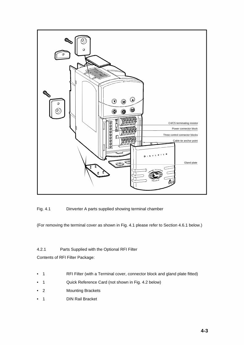
Fig. 4.1 Dinverter A parts supplied showing terminal chamber
(For removing the terminal cover as shown in Fig. 4.1 please refer to Section 4.6.1 below.)
4.2.1 Parts Supplied with the Optional RFI Filter
Contents of RFI Filter Package:
• 1 RFI Filter (with a Terminal cover, connector block and gland plate fitted)
• 1 Quick Reference Card (not shown in Fig. 4.2 below)
• 2 Mounting Brackets
• 1 DIN Rail Bracket

4-4
• 2 M4 Taptite Screws for fixing 2 of the 3 supplied Brackets to Drive heatsink. (Suitable for cross-head or flat-head screwdrivers.)
Upper mounting bracket
M4 Taptite screw
Plug-in connector block
Terminal cover
Gland plate
M4 Taptite screw
Lower mounting bracket
DIN-rail mounting bracket
Fig. 4.2 RFI Filter parts supplied showing terminal chamber
(For removing the terminal cover as shown in Fig. 4.2 please refer to Section 4.6.4 below.)

4-5
4.3 Storage and Transportation
4.3.1 Storage
The drive can be safely stored in its “as delivered” state for up to 2 years provided the driveenvironment is in the limits specified in Section 3.3 (Drive Environmental Data).
Following a 2 year storage period the DC bus electrolytic capacitors will need reforming.This is a simple operation requiring a variable AC source (such as a Variac or variableautotransformer). Provided the DC electrolytic capacitors are reformed at the end of eachand every 2 year storage period, the drive can be stored indefinitely.
The reforming process is carried out as follows.
• Connect the drive as shown:
•
V
DriveSupply200 ~ 240VAC
50/60 Hz
L1
L2
Fig. 4.3 Electrical arrangement for reforming DC bus electrolytic capacitors
• No other control/power connections are necessary.
• Suitably fuse the input to the Variac using slow-blow type fuses (e.g. 0.5A or similar), anda similar rated fuse to the input of the drive.
• With the Variac set to 0VAC output, turn on the supply and gradually increase the voltageto the drive (e.g. 4.5 VAC per minute with a maximum of 5VAC steps). Over a period of 1hour increase the voltage from 0VAC to 275VAC. At the end of the 1 hour period, with275 VAC applied remove the drive from the supply.
• The reforming process is now complete and the drive can be stored for another 2 years.
4-6
4.3.2 Transportation
The drive can be either transported in its own supplied packaging or already mounted in itsassembled enclosure.
Section 3.3 (Drive Environmental Data) gives details concerning vibration and other relevantdata. However, please ensure severe shocks are avoided during transportation especiallywhen already mounted in an enclosure as the shock capability of the drive, although good,will not tolerate dropping. Therefore it is always good practice to inspect the drive followingtransportation to ensure that the drive has not been damaged.
4.4 Planning the Installation.
The following conditions must be met when planning the installation of the drive or a numberof drives in an enclosure:
• The drive environment is acceptable (the acceptable limits are defined in Section 3.3(Drive Environmental Data).
• The maximum permissible ambient temperature of the drive is not exceeded (see Section3.3).
• The EMC (Electromagnetic Compatibility) requirement is met.
• The electrical installation meets the safety requirements.
A typical procedure to plan the installation in an enclosure is as follows:
1. Decide how many drives are to be installed in the enclosure.
2. Decide whether the drives require the optional RFI filter.(Either all or none will require them.)
3. Decide which (if any) drives require an optional braking resistor, and whetherthis is to be mounted external or internal to the enclosure.
4. Decide how the drives are to be vertically mounted in the enclosure, either:
• DIN-rail mounted, or
• Surface, wall or panel mounted.
5. Estimate the drive ambient operating temperature, switching frequency andoutput current required. From the data given in Figs 3.2 and 3.3 (in Section 3.2 ) and theoperating environment of the drive decide whether the drive needs the Vent Coversfitting, and determine from the Drive Data in Section 3.2 the heat loss of the drive andfilter.
6. Plan the installation layout using Fig. 4.4 below as a guide. Further details aregiven in this Section, but also refer to Section 5 on Electrical Installation.

4-7
7. Decide whether the enclosure is to be sealed or ventilated. Ensure that the heatgenerated within the enclosure does not cause the enclosure ambient to exceed thedrives rating and that there is enough enclosure surface area or air flow to meet theserequirements. See Section 4.7 for calculation details.
8. Re-arrange the enclosure layout, if necessary, by repeating the above steps 1through to 7 until all criteria are met.
≥100mm (4in)
≥5mm (¼in)
Optional braking resistor for the relevant DrivesExternal: Mount on top surface of enclosure.Internal: Mount in top part of enclosure.
Controller for the DrivesLocate as required.
Signal cablesPlan for all signal cables to be routed at least 300mm (12in) distant from any AC power cable.
RFI filtersWhen an RFI filter is required, install a separate RFI filter for each Drive.
AC supply isolator, contactor, and fuses or MCBs Locate as required. All AC supply
cablesEnclosure wall
Drives and RFI filtersEnsure minimum clearances are respected.
Back-plate
≥5mm (¼in)
≥100mm (4in)
Alternative location of fuses or MCBsLocate as required.
≥5mm (¼in)
Layout when EMC requirements do not apply
≥5mm (¼in)
Fig. 4.4 Planning the layout of the enclosure
4-8
Further details concerning installation are given in the following sections. However thefollowing general details are helpful:
1. The drive must be located in an environment that is free from dust (unless ventcovers fitted), corrosive vapours, gases and all liquids, including condensation ofatmospheric moisture.
2. If condensation is likely to occur when the drive is not in use, install an anti-condensation heater. This heater must be switched off when the drive is in use;automatic switching is recommended.
3. Do not locate the drive in a classified hazardous area, unless the drive isinstalled in an approved enclosure and the enclosure and the installation is approved.
4. Install the drive vertically.
5. Observe the requirements for ambient temperature if the drive is to be mounteddirectly above any heat generating equipment, such as another drive.
6. If the drive is to be installed directly beneath other equipment, such as anotherdrive, ensure that the drive does not cause the ambient temperature requirements of theequipment to be exceeded.
7. Allow at least 100mm (4”) clearance above and below the drive.
8. Allow at least 5mm (0.25”) clearance each side of the drive.
9. Mount the RFI Filter to the left of the drive to minimise the cable length betweenthe drive and the RFI filter.
4.5 Mounting the Drive
Before the drive is mounted, a decision has to be made regarding the ingress protectionrequirement as to whether the Vent Covers need to be fitted. (See Section 4.4). From thedata given in Section 3.2, the operating ambient temperature, switching frequency and motorfull load current, a decision can be made.
If the vent covers need to be fitted for environmental ingress protection, please ensurecorrect orientation and firm fit.

4-9
Fig. 4.5 Fitting the Vent Covers
Depending on whether the drive is to be DIN rail mounted or panel mounted the mountingmethods are as follows:

4-10
4.5.1 DIN Rail Mounting
DIN-rail mounting bracket
M4 Taptite screw
Lower mounting bracket
M4 Taptite screw
Fig. 4.6 Fitting the brackets to the heatsink in preparation for DIN rail mounting

4-11
≥5mm (¼ in)
≥5mm (¼ in)75mm (3 in)
44mm(1¾ in)
108mm(4¼ in)
≥100mm(4 in)
≥100mm(4 in)
140mm(5½ in)
DIN-rail
Area occupied by the Drive
Lower mounting bracket
Nearest objects to the Drive
∅ M5( /16 in)3
Fig. 4.7 Preparing the panel/wall or surface for DIN rail mounting
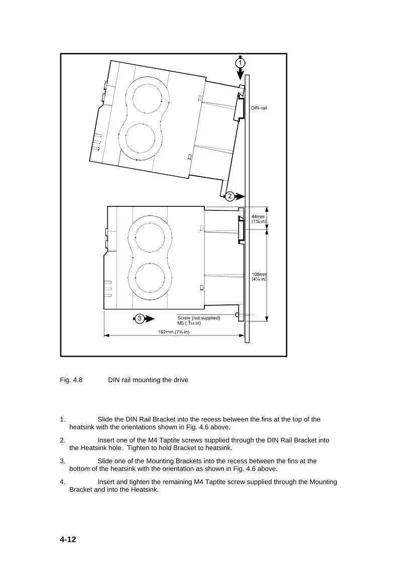
4-12
DIN-rail
Screw (not supplied)M5 ( /16 in)3
Fig. 4.8 DIN rail mounting the drive
1. Slide the DIN Rail Bracket into the recess between the fins at the top of theheatsink with the orientations shown in Fig. 4.6 above.
2. Insert one of the M4 Taptite screws supplied through the DIN Rail Bracket intothe Heatsink hole. Tighten to hold Bracket to heatsink.
3. Slide one of the Mounting Brackets into the recess between the fins at thebottom of the heatsink with the orientation as shown in Fig. 4.6 above.
4. Insert and tighten the remaining M4 Taptite screw supplied through the MountingBracket and into the Heatsink.

4-13
5. Drill and tap a 5mm (3/16”) mounting hole 108mm (4 1/4”) vertically below thecentre of the 35mm (1 3/8”) DIN rail on the back panel of the enclosure where the drive isto be installed. (See Fig. 4.7 above.)
6. Locate the drive on the DIN rail as indicated in Fig. 4.8 above.
7. Secure the lower Mounting Bracket to the back panel of the enclosure using thehole made in Step 5 above with a 5mm (3/16”) screw (not supplied).
4.5.2 Panel Mounting
Upper mounting bracket
M4 Taptite screw
Lower mounting bracket
M4 Taptite screw
Fig. 4.9 Fitting the brackets to the heatsink in preparation for panel mounting

4-14
≥5mm (¼ in)
≥5mm (¼ in)75mm (3 in)
152mm(6 in)
≥100mm(4 in)
≥100mm(4 in)
140mm(5½ in)
Area occupied by the Drive
Mounting bracket
Nearest objects to the Drive
∅ M5( /16 in)
Mounting bracket
3
∅ M5( /16 in)3
Fig. 4.10 Preparing the panel/wall or surface for panel mounting
Back-plate
Mounting bracket
Screw (not supplied)
Screw (not supplied)
Fig. 4.11 Panel mounting the drive
4-15
1. Slide the 2 Mounting Brackets into the recesses between the fins at the top andbottom of the heatsink with the orientation as shown in the Fig. 4.9 above.
2. Insert and tighten the 2 supplied M4 Taptite screws through the MountingBrackets and into the Heatsink.
3. Drill and tap two mounting holes 152mm (6”) vertically apart on the centre line ofthe back panel of the enclosure where the drive is to be installed (see Fig. 4.10 above).
4. Secure the drive via the Mounting Brackets to the back panel of the enclosureusing the holes made in Step 3 above with two 5mm (3/16”) screws (not supplied). (SeeFig. 4.11 above.)
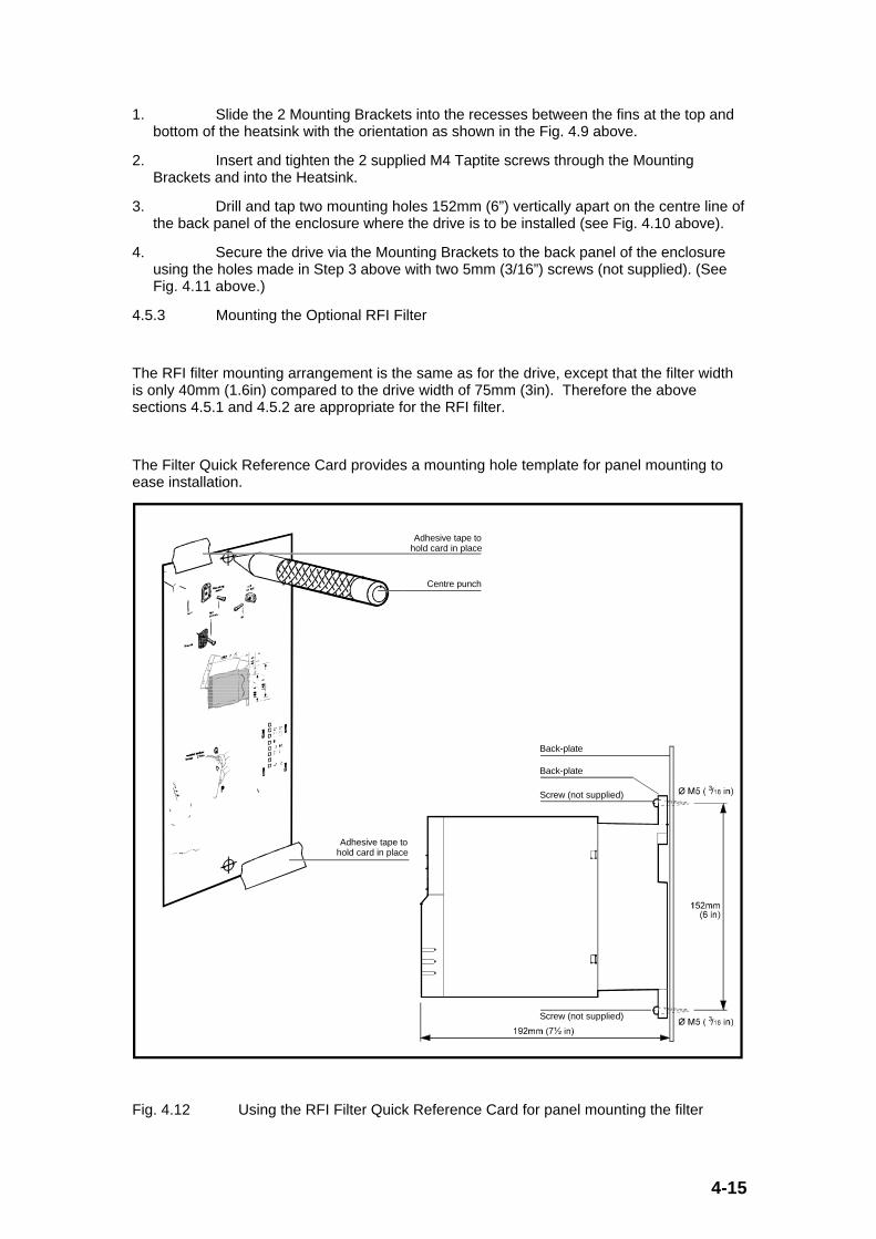
4.5.3 Mounting the Optional RFI Filter
The RFI filter mounting arrangement is the same as for the drive, except that the filter widthis only 40mm (1.6in) compared to the drive width of 75mm (3in). Therefore the abovesections 4.5.1 and 4.5.2 are appropriate for the RFI filter.
The Filter Quick Reference Card provides a mounting hole template for panel mounting toease installation.
Adhesive tape to hold card in place
Centre punch
Adhesive tape to hold card in place
Back-plate
Back-plate
Screw (not supplied)
Screw (not supplied)
Fig. 4.12 Using the RFI Filter Quick Reference Card for panel mounting the filter
4-16
4.5.4 Mounting the Optional Braking Resistor
Warning
The Braking Resistor must be mounted so that the heat generated will not damage otherlocal components within the panel.
If the Braking Resistor is to be mounted externally to the enclosure, it must be fitted with astrong grille to allow the heat to escape but still give protection from human contact.
Please refer to Section 5.3.4 for electrical protection and sizing of the braking resistor.

4-17
4.6 Cabling the Drive
The following details provide an overview to how the drive should be connected to thesupply, motor, drive controller and optional RFI filter and braking resistor if used. Furtherdetails are given in Section 5, Electrical Installation, with regard to cable termination points,cable sizes etc.
4.6.1 Access to the Drive Terminal Chamber
All of the electrical connections to the drive are made via the Gland Plate and terminated inthe chamber underneath the Terminal Cover.
DC/DC
275VAC
varistor
Current processing
DC voltage processing
PWM
2 wire RS485
Digital/analoginputs/outputs
Optional RFI filter
AC supply
Isolator, and fuses or MCB
Optional second AC supply phase
DCCT
Power stage
Microprocessor
User interface control
V/f + machine current control
Diagnostics
Power stage temperatureCurrent Trips
Interface circuits
Display and keypad
Volt-free contact
PWM
UVW
IGBT (braking)
Optional external resistor
Brake resistor protection
Brake+
Control stage
Current and trips
Control supplies
Trips
3φ AC
DCCTL1 (L)
L2 (N)
PE
IGBT bridge
Drive
460VAC
varistors Interfacing
Fig. 4.13 Tool removal of the Terminal Cover for access

4-18
To gain access into the Terminal Chamber the Terminal Cover must be removed/unclipped.To do this use a φ3mm (1/8”) flat-head screwdriver and insert into the aperture at the bottomright hand side of the drive. Push the blade up vertically until the Terminal Cover isunclipped and can then be pulled off by hand.
The Gland Plate can now be unclipped and pulled out for ease of cabling.
4.6.2 Gland Plate
The Gland Plate has two φ13mm (1/2”) diameter holes and a similar sized “knockout”.Depending on the installation requirement, and environmental protection that the driveneeds, the Gland Plate can either be used with or without cable glands (not supplied) oneither 2 or 3 positions depending on whether the “knockout” is pushed/drilled out.
Back-plate
Mounting bracket
Screw (not supplied)
Screw (not supplied)
Fig. 4.14 Terminal chamber with gland plate installed prior to cabling
If suitable cable glands are used, the drive environmental classification (IP20/NEMA 1 etc.) ismaintained. Without cable glands fitted, or other means of restricting access, the drive isonly IP10 with no NEMA classification provided the gland plate is still fitted (otherwise IP00 ifit is not).

4-19
The Gland Plate holes are allocated as follows to aid cabling; (Please note that the glandswill not accept the cabling as described with shielding/screening.)
X - AC Supply Cables (Gland will accept 3 x 2.5mm2/14AWG)
Y - Motor and Braking Resistor Cables (Gland will accept 6 x 1.0mm2/18AWG).
Z - Control Cables (Gland will accept 10 x 0.5mm2/20AWG).
Gland XAC supply cables
Gland YMotor and braking resistor cables
Gland ZControl cables
Fig. 4.15 Completed cabling using gland plate and glands
Once the cabling has been completed the Gland Plate can be snapped back into position (asindicated by the arrow on the Gland Plate), with the necessary cable glands fitted.
At this stage, the tie point in the Terminal Chamber can be used to tie any wires into positionto help segregate Control from Power.

4-20
Finally, clip the Terminal Cover back into position, ensuring that the tongue aligns in the holein the drive. See the figure below.
4.6.3 Cabling Notes
• Each of the Power Connector terminals can accept cables up to a total maximum 2.5mm2
(12AWG) in cross sectional area. Only use a φ3mm (0.125”) flat head screwdriver andonly tighten up to 0.5Nm (4.4 lb.in) torque.
• Each of the Control Connector terminals can accept cables up to a total maximum of2.5mm2 (12AWG) in cross sectional area. Only use a φ3mm (0.125”)screwdriver and onlytighten up to 0.4Nm (3.5 lb.in) torque
• Always segregate Control and Power cabling by at least 300mm (12”) where possible.
• Segregate supply and motor cabling by at least 300mm (12”) where possible for goodEMC practice.
• Use armoured, shielded cable or conduit to connect the motor to the drive where EMCemission standards must be met and the motor cable passes outside the drive enclosure.In this case connect the armour, shield or conduit to the drive and the motor frame.

4-21
4.6.4 Cabling the Optional RFI Filter
The cabling of the Filter is similar to cabling the drive. The main differences are detailedbelow for the Filter.
Access to the Filter Terminal Chamber and cabling are illustrated in the figures below.
Terminal cover
Recess
3mm ( /8 in) screwdriver
1
Underside of the RFI filter
Fig. 4.16 Tool removal of the Filter Terminal Cover for access
Power connector
Gland plate
Fig. 4.17 Filter terminal chamber with gland plate installed prior to cabling

4-22
Fig. 4.18 Removing the pluggable filter terminal block to enable cabling
Gland PAC supply cables Gland Q
Output cables
Fig. 4.19 Completed cabling using gland plate and glands prior to insertion of gland plateand plug-in terminal block

4-23
The Gland Plate holes for the RFI filter are allocated as follows to aid cabling; (Please notethat the glands will not accept the cabling as described with shielding/screening.)
P - Input Supply Cables (Gland will accept 3 x 2.5mm2/14AWG)
Q - Output Cables to Drive (Gland will accept 3 x 2.5mm2/14AWG).
Once the cabling has been completed the Gland Plate can be snapped back into position (asindicated by the arrows on the Gland Plate), with the necessary cable glands fitted.
Finally, clip the Terminal Cover back into position, ensuring that the tongue aligns in the holein the filter.
4.6.5 Cabling the Optional Braking Resistor
Cabling the braking resistor is very dependent on the resistor used. The only additionalpoints apart from the details given in Sections 4.6.1 to 4.6.4 above, are that the cabling usedmust have suitable insulation with regard to the operating temperature, and have suitablescreening/shielding for EMC emission standards. The braking resistor will heat the cable viaconducted heat along the electrical connections. Therefore a high temperature insulation isrecommended especially at the brake resistor end of the cable. (At the drive end, normalinsulation is adequate.) The cable should be screened or armoured if passing outside thedrive enclosure and EMC emission standards apply.
4.7 Enclosure Heat Dissipation Calculations
4.7.1 Sealed Enclosures
To maintain the correct level of cooling for the drive when it is installed in a sealed enclosure,the heat generated by all of the equipment within the enclosure must be included in thecalculations to determine the cooling area needed (and therefore wall area for the correctenclosure size). The equation to establish the cooling area/wall area is as follows:

4-24
Ae = P/[k(Ti - Tamb)]
where: Ae is the total unobstructed heat conducting area in m2, equal to thesum of all the enclosure surfaces/walls which are not in contact with anyother surface.
(Note: Multiply Ae value above by 10.8 to obtain area in ft2 instead of m2.)
P is the total power in W dissipated by all the heat sources within theenclosure
k is the heat transmission coefficient of the enclosure material inW/m2/oC (e.g. a value of 5.5 W/m2/oC for typical 2mm (3/16”) painted sheetsteel)
Tamb is the maximum expected ambient temperature external to theenclosure in oC
Ti is the maximum permissible operating temperature of theenclosure internal equipment (e.g. the drive) in oC
If possible, locate heat generating equipment (apart from Braking Resistors) in the lower partof the enclosure to encourage internal convection. The best place for the Braking Resistorsis external to the sealed enclosure, but if this is not feasible, site them at the top of theenclosure to avoid heating all other equipment by convection.
4.7.2 Ventilated Enclosures
If the ingress protection of a sealed enclosure is not required, then a ventilation fan may beused to reduce the enclosure size compared to that required for a sealed enclosure. Tocalculate the volume of air for the ventilation fan use the following equation:
V = 3.1kP/(Ti - Tamb)
where: V is the ventilation fan air volume in m3/hour
(Note: Multiply V value above by 0.59 to obtain area in ft3/minute instead ofm3/hour.)
P is the power in W dissipated by all the heat sources in the enclosure
Tamb is the maximum expected ambient temperature external to theenclosure in oC
Ti is the maximum permissible operating temperature of theenclosure internal equipment (e.g. the drive) in oC
k is the ratio of sea-level atmospheric pressure to the actual pressureat the installation (typically a safety factor of 1.20 to 1.30 should be used toallow for pressure drops due to dirty air filters).
__________

5-1
5.0 Electrical Installation
5.1 Warnings
Voltages/Electric Shock Risk
The voltages present in the drive are capable of inflicting a severe electric shock and may belethal.
The stop function of the drive does not remove dangerous voltages from the drive or thedriven motor.
Mains supplies to the unit must be disconnected using an approved isolation device beforeany cover is removed or servicing work is performed. Wherever possible the disconnectiondevice should be located close to and within sight of the drive.
Stored charge - to service personnel, and to plug/socket
The drive contains capacitors which may remain charged to a potentially lethal voltage afterthe supply is removed. An interval of 5 minutes must be allowed between disconnecting thesupply and gaining access to the connections to the drive.
Special attention must be given if the drive is installed in equipment which is connected tothe supply through a plug and socket. This is because the capacitors are connected to thedrive input circuit through diodes, so that if they were to fail the plug would become “live”. Ifthe equipment side of the plug can be touched when removed from the socket, then meansmust be provided for automatically isolating the plug from the drive input when it isdisconnected - for example, a latching contactor.
Protection of motor
The drive has facilities for protecting the motor from overload either via current monitoring or amotor thermistor. The current monitoring protective function must be correctly set up in order toavoid the risk of motor over-heating in the event of electrical or mechanical failure. It will not protectthe motor from over-heating at low speed, due to the reduction in the effectiveness of the cooling fan.The use of a temperature sensing thermistor in the motor winding connected to the drive thermistortrip input is recommended if operation at high torque and low speed is required.
EMC
The drive is designed to high standards of electromagnetic compatibility (EMC). EMC data isprovided in the manual and in the EMC data sheet, including advice for achievingcompliance with specific emission standards. Under extreme conditions the drive may causeor suffer from disturbance due to electromagnetic interaction with other equipment. Theinstaller is responsible for ensuring compliance with regulations in force at the place of use.

5-2
5.2 Overview and Notes
5.2.1 Access to Electrical Connections
Refer to Section 4.6.1 and 4.6.2 giving details concerning access to the Terminal Chamber ofthe drive and use of the Gland Plate.
0V common
RS485 input
Run forward
Run reverse
Drive enable
External trip
Analog speed reference
Status relay contacts (250VAC, 2A N/O) (optional connection)
Optional braking resistor ≥100Ω
Optional RFI filter
AC supplyFuses and isolator
Analog frequency output signal
Digital inputs
C4/C5 terminating resistor (100Ω) across C4~C5 (0 ~ 20mA) RS485 inputs
Brake
0V common
+10V, 5mA maximum
0V common
Gland X: 3 x 2.5mm (14AWG)
Gland Y: 6 x 1.0mm (18AWG)
Gland Z: 10 x 0.5mm (20AWG)
2
2
2
Optional
Fig. 5.1 Typical electrical connections for operation of the drive
5.2.2 Earthing/Ground Connections
Earthing (grounding, equipotential bonding)
The drive must be earthed/grounded through a conductor adequate to carry the prospectivefault current.
The relevant drive connection ( ) can be connected either via the RFI filter or directly if nofilter is used.
The wiring must conform with local regulations and codes of practice.
Ground loop impedance must conform to the requirements of local industrial safelyregulations. The ground connections should be inspected and tested at appropriate andregular intervals.

5-3
5.2.3 AC Supplies
The drive is designed to work from either one phase (220VAC nominal) and neutral (star-point) from a three phase system (380VAC nominal), or from two phases (line to line)(220VAC nominal) from a three phase system (220VAC).
The input protection within the drive ensures that the potentials between L1 to Ground, L2 toGround, and, L1 to L2, can be within the 240V + 10% supply capability. Therefore the drivewill work successfully from grounded delta supplies.
5.2.4 EMC Wiring Layout Recommendations
Electromagnetic Compatibility (EMC) considerations can have an important effect on thewiring arrangement.
Section 5.4 below gives guidance on wiring to prevent interference, and also wherecompliance with specific EMC emission standards is required. Section 4.5.3 includesinstructions on mechanical installation of RFI Filters where required.
5.2.5 Fuses and Cable Sizes
The wiring and fusing must conform with the local regulations and codes of practice.
Cabling, wiring regulations, fusing
The power supply to the drive must be fitted with suitable protection against overload andshort circuits. The table below shows recommended fuse ratings and cable sizes for all powerconnections. Failure to observe this recommendation will cause a risk of fire. In the event ofa conflict with local wiring regulations, the local regulations prevail. The table is based onPVC insulated copper conductors with or without shielding as required, laid in accordancewith the manufacturer’s instructions.
All cable sizes are based on the 100% full load RMS currents, with a 50°C ambienttemperature with multi-core cables housed in trunking/conduit.

5-4
The UL listing of this drive is conditional on the use of UL listed fuses of the following type:
Bussmann Limitron KTK-15A (fast acting type)(600VAC 100kA breaking capacity 10.3 x 38mm Midget Fuse)
Since a current surge occurs when AC power is applied to the drive, the use of slow-blowfuses is recommended. As an alternative to fuses, an MCB (Miniature Circuit Breaker) orMCCB (Moulded Case Circuit Breaker) may be used if equipped with adjustable thermal andmagnetic trip devices with suitable ratings.
DIN1220025A DIN1220037A DIN1220055A DIN1220075A
Supply Fuse Rating(A)
(slow-blow type or
similar MCB,MCCB)
6 6 10 16
Recommended Minimum Cross Sectional Areas Per Conductor
AC Supply and RFIFilter Cables
(240VAC minimumrating)
1.0mm2
(18AWG)
1.0mm2
(18AWG)
1.5mm2
(16AWG)
2.5mm2
(14AWG)
Braking ResistorCables
(400VDC minimumrating
unshielded orshielded twin)
1.0mm2
(18AWG)
1.0mm2
(18AWG)
1.0mm2
(18AWG)
1.0mm2
(18AWG)

5-5
Motor Cables
(240VAC minimumrating
4-coreunshielded/shieldedor 3-core shielded)
1.0mm2
(18AWG)
1.0mm2
(18AWG)
1.0mm2
(18AWG)
1.0mm2
(18AWG)
Control Cables 0.5mm2
(20AWG)
0.5mm2
(20AWG)
0.5mm2
(20AWG)
0.5mm2
(20AWG)
5.2.6 Cable Lengths
The cable sizes given in Section 5.2.5 do not take into account voltage drops. As a roughguide, the cables used should have a voltage drop of less than 5% of the nominal voltage. Ifthis voltage drop is exceeded, larger cross-sectional area cables should be used to avoid lossof motor torque at high speed.
Please refer to Section 3.7.1.5 with regard to cable lengths (from the drive to the motor) andthe installation meeting the relevant EMC requirements.
For cable lengths greater than 100m (330ft) between the drive and the motor please consultyour supplier with regard to meeting any EMC requirements and possible drive operatingproblems.
5.2.7 Matching Motor(s) to the Drive
It is important that the motor(s) connected to the drive is(are) properly rated. In particular,ensure that the total connected motor(s) power rating is less than or equal to the drive powerrating. In addition to this ensure that the total connected motor(s) current rating is less thanor equal to the drive current rating. Finally ensure that the motor(s) voltage rating is similaror less than the drive AC supply voltage. For multi-motor arrangements, it is essential thateach motor connected to the same drive has the same voltage rating.
5-6
5.2.8 Multi-Motor Arrangements
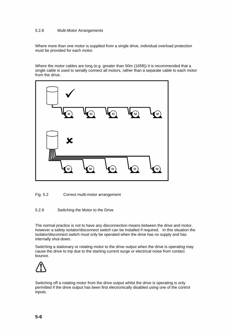
Where more than one motor is supplied from a single drive, individual overload protectionmust be provided for each motor.
Where the motor cables are long (e.g. greater than 50m (165ft)) it is recommended that asingle cable is used to serially connect all motors, rather than a separate cable to each motorfrom the drive.
Fig. 5.2 Correct multi-motor arrangement
5.2.9 Switching the Motor to the Drive
The normal practice is not to have any disconnection means between the drive and motor,however a safety isolator/disconnect switch can be installed if required. In this situation theisolator/disconnect switch must only be operated when the drive has no supply and hasinternally shut-down.
Switching a stationary or rotating motor to the drive output when the drive is operating maycause the drive to trip due to the starting current surge or electrical noise from contactbounce.
Switching off a rotating motor from the drive output whilst the drive is operating is onlypermitted if the drive output has been first electronically disabled using one of the controlinputs.

5-7
5.3 Power Connections
5.3.1 AC Supply Connections
Using the Cable Gland position X (see Fig. 5.1 in Section 5.2.1) the supply connections arerouted through to the Power Connection positions (L1, L2 and Ground (include terminalsymbol)).
A recommended electrical arrangement is shown as follows:- (Please refer to local wiringregulations for guidance.)
AC supply phases Isolator Fuses
ContactorK1
Optional RFI filter
Drive
Jumper (not essential)
Fig. 5.3 Connecting the drive to the AC supply
A simple external on/off control arrangement for the AC supply to the drive is:
On
Off
K1 contact
K1
Auxiliary control supply110V / 240V AC
Contactor coil
Fig. 5.4 Simple control arrangement for AC supply contactor
5-8
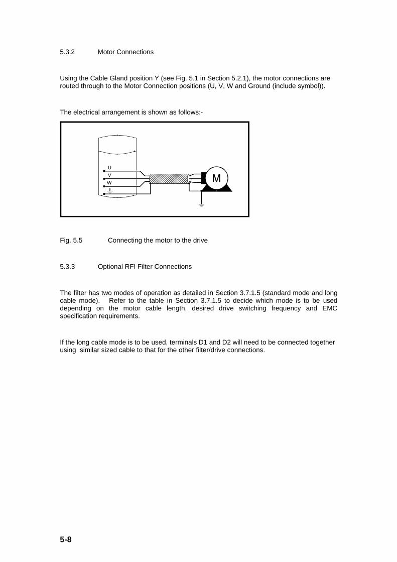
5.3.2 Motor Connections
Using the Cable Gland position Y (see Fig. 5.1 in Section 5.2.1), the motor connections arerouted through to the Motor Connection positions (U, V, W and Ground (include symbol)).
The electrical arrangement is shown as follows:-
Fig. 5.5 Connecting the motor to the drive
5.3.3 Optional RFI Filter Connections
The filter has two modes of operation as detailed in Section 3.7.1.5 (standard mode and longcable mode). Refer to the table in Section 3.7.1.5 to decide which mode is to be useddepending on the motor cable length, desired drive switching frequency and EMCspecification requirements.
If the long cable mode is to be used, terminals D1 and D2 will need to be connected togetherusing similar sized cable to that for the other filter/drive connections.
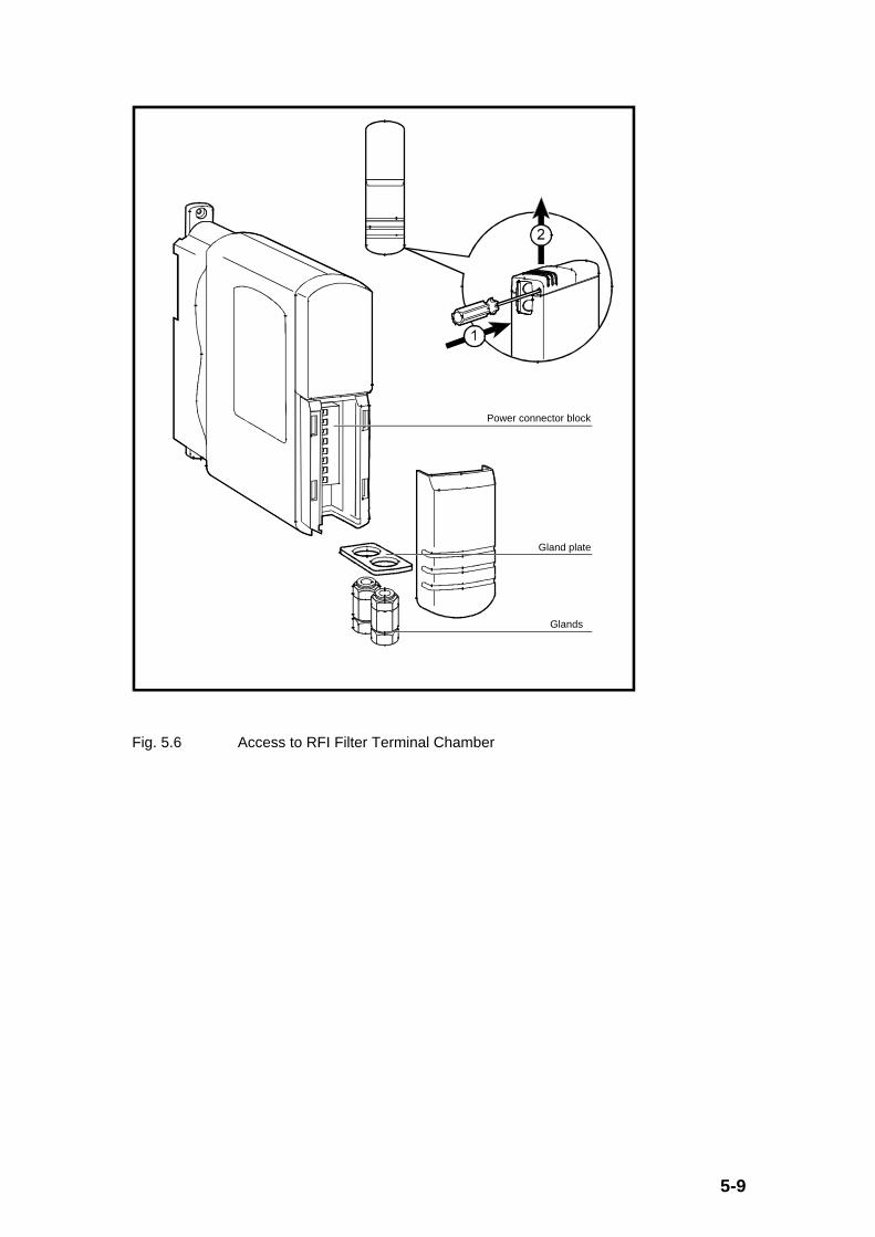
5-9
Power connector block
Gland plate
Glands
Fig. 5.6 Access to RFI Filter Terminal Chamber

5-10
Insulated boot-lace ferrules 8 x 25mm
3mm ( /8mm) dia1
Fig. 5.7 Cabling the RFI Filter
Using the Cable Gland position P (see Fig 5.7 above) the supply to filter connections arerouted through to the Power Connection positions (L1, L2 and Ground (include terminalsymbol)).
Using the Cable Gland position Q (see Fig 5.7 above) the filter to drive connections arerouted through to the Power Connection positions (L1’, L2’ and E’).
Ensure the above conditions are met in order to meet the EMC specifications defined inSection 3.7.1.5.

5-11
5.3.4 Optional Braking Resistor Connections
Braking resistors
In the event of unexpectedly high braking energy or loss of control of the braking circuit,excessive dissipation may occur in the braking resistor. Depending on the rating, position anddetailed design of the resistor this may cause a fire hazard. It is recommended that someform of protection circuit be fitted. One suitable method is a thermal overload relay, arrangedto disconnect the AC supply to the drive in the event of excessive energy being supplied tothe resistor.
Using the Cable Gland position Y (see Fig. 5.1 in Section 5.2.1), the brake resistorconnections are routed through to the Brake Connection positions (‘+’ and ‘Brake’ (includesymbol)).
The electrical arrangement is shown as follows:-
Braking resistor100Ω minimum
Thermal protection element Th1
Fig. 5.8 Connecting the braking resistor to the drive

5-12
On
Off
K1 contact
K1
Auxiliary control supply110V / 240V AC
Th1 contact
Contactor coil
Fig. 5.9 Control protection for the braking resistor
5.3.4.1 Braking Resistor Sizing - Essential Requirements
Any braking resistor used must be able to tolerate the pulsed DC power that the driveapplies. During drive operation, if the motor regenerates due to an overhauling load ordeceleration, energy is fed back into the drive. This causes the DC bus voltage within thedrive to rise, and at a nominal value of 391VDC, the brake resistor is electronically switchedin circuit. The electronic switch remains closed until the DC bus voltage falls below 389VDC.
Under worst case operating conditions the braking resistor will see a transient/pulse voltageof up to 420V and must be sized to meet this surge. Therefore, with a 100Ω braking resistorthe instantaneous power capability must be at least 1.8kW. Higher resistance values for thebrake resistor will lower this instantaneous power requirement.
100ΩΩ is the minimum value of braking resistor that should be fitted.
Recommended braking resistance values for the drives are as follows: (providing a 1.5 timescontinuous power braking capability, e.g.. providing (1.5 x 0.55 kW) braking capability for a0.55kW drive).

5-13
DIN1220025A DIN1220037A DIN1220055A DIN1220075A
Typical Braking ResistorResistance
330Ω 220Ω 150Ω 120Ω
Instantaneous PeakPower Requirement
(based on short term
application of 420VDC)
0.5kW 0.8kW 1.2kW 1.5kW
5.3.4.2 Braking Resistor Sizing - Optimisation
To further optimise the braking resistor used, it is important to understand the brakingrequirements and the nature of the mechanical load. To this end, the peak and averageregenerative power requirements need to be calculated as follows. The peak regenerativepower is the peak power that is produced by the mechanical load and will eventually bedissipated by the braking resistor. The average regenerative power is the averageregenerative power produced by the mechanical load. Neither of these 2 figures affect theinstantaneous peak power requirement of the braking resistor (given in Section 5.3.4.1above) as this instantaneous power is defined by the drive operation and is not influenced bythe mechanical load.

5-14
The figure below shows the braking power for a motor/drive during a typical speed cycle.
Shaft speed
Braking power
Time
Time
Fig. 5.10 Braking power for various shaft speed changes
The maximum power (Pmax) that the resistor must dissipate is dependent on the requiredmotor deceleration, initial deceleration speed and the load inertia (ignoring losses andloading), as follows:
Pmax = J x (angular deceleration in rad/sec2) x (initial angularspeed in rad/sec)
= 100.(fmax). J.(4π/p)2/(tmin)
where: fmax maximum operating frequency of the drive in Hz
J Total inertia referred to motor in kg.m2.
p Number of motor poles (e.g. 2,4, 6 or 8 as set in #0.42 etc.)
tmin Minimum required deceleration time parameter (#0.04) set in thedrive as seconds/100Hz.
If inertia is given in lb.ft2 then the above constant of 100 becomes 2375.
If Pmax is greater than 1.5 times the drive power a larger drive is necessary to achieve thedesired deceleration.
If Pmax is less than 0.2 times the drive power rating a braking resistor is usually notnecessary, as the power should easily be dissipated in the motor and drive losses.
5-15
Once the value of Pmax is calculated, the applicable braking resistor value can bedetermined as follows:
R ≤ (390)2/Pmax
where: R Resistance in ohms of Braking Resistor (select the nextlower preferred value)
390 is the nominal DC voltage applied to the Braking Resistor
provided R ≥ 100Ω
The braking resistor will also require a continuous or average power rating for correct sizing.To calculate the average power required, the energy loss (Eloss) per braking cycle must firstbe known.
Eloss = (0.5). J. (4π/p)2. (f12 - f22)
where: Eloss Energy to be removed in Joules
J Total inertia referred to motor in kg.m2.
p Number of motor poles (e.g. 2,4, 6 or 8 as set in parameter #0.42.)
f1 Highest operating frequency of motor in Hz
f2 Minimum frequency of motor after deceleration (typically 0) in Hz
Therefore, from consideration of the duty cycle, the average power dissipation (Pav) is asfollows:
Pav = Eloss/ (t1 + t2)
where: Eloss Energy to be removed in Joules
t1 Duration of braking period in seconds
t2 Time between braking periods in seconds

5-16
Fig. 5.11 below illustrates how the braking resistor characteristic must meet the various limitscalculated above. (The resulting braking resistor characteristic also provides a characteristicthat the thermal protection device must have. The thermal protection device must have acharacteristic that matches (but still protects) the braking resistor whilst still allowing thebrake resistor to provide the drive braking control required.) The (Pmax/2) and (tdecel/2)terms are the average power and times for a linear deceleration from fmax where the initialdeceleration power is Pmax.
Power dissipated in braking resistor
Instantaneous peak power
Pmax
(Pmax/2)
Pav
(2 x 10 ) tdecel/2 Deceleration time from maximum speed (tdecel)
Time (seconds)
Braking resistor rating must lie in this region
−3
Electrical requirement(eg. 1.5kW for 120Ω)
Mechanical requirement
Fig. 5.11 Braking resistor rating requirements
5.4 EMC Considerations
5.4.1 General Principles
These Drives are intended to be used with appropriate motors, controllers, electricalprotection components and other equipment to form complete end products or systems.Compliance with safety and EMC regulations depends upon installing and configuring theDrives correctly, including using the specified RFI Filters. The Drives must be installed onlyby professional assemblers who are familiar with the requirements for safety and EMC. Theassembler is responsible for ensuring that the end product or system complies with all therelevant laws in the country where it is to be used. The Dinverter A EMC Data Sheet is alsoavailable giving detailed EMC information.
These Drives will comply with the standard for emission, EN50081-2, only if the instructionsgiven in Section 5.4.3 are followed closely.

5-17
5.4.2 Routine EMC Precautions
These precautions are recommended where strict compliance with emission standards is notrequired. The risk of disturbing adjacent electronic equipment is minimised by followingthese precautions. Where the drive is installed in a residential area, or adjacent to sensitiveelectronic equipment using radio receivers or similar, it is recommended that the fullprecautions given in Section 5.4.3 are taken.
Enclosure
Install the Drive(s) in a metal enclosure. This does not need to be a special EMC enclosure.
Motor Cable
Ensure that the motor cable is shielded and its length does not exceed 100m (330ft).
Wiring Guidelines
Observe the wiring guidelines given in the following figure and attached key. The details ofindividual installations may vary, but details which are indicated in the figure to be importantfor EMC must be strictly adhered to.

5-18
Back-plate
V
+
W
U
Drive
Optional external braking resistor
L1/LL2/N
Enclosure
IsolatorContactor
AC supply
Ground
Key to symbols
Single power cable
Two-core power cable or two single power cables
Ground cable
0V
Output 3
Output 2
Output 1
Ground
System controller
Control cables to the Drives
No sensitive circuits permitted in this zone
Power-ground bus-bar
L1/L
L2/N
Four-core power cable(3-phase + ground)
Fuses or MCB
Fig. 5.12 Wiring guidelines for Dinverter A drive - routine EMC precautions
The numbers in the above figure relate to the following recommendations:
General features:
1 Single power-ground bus-bar, or low-impedance ground terminal.
2 Incoming AC supply ground connected to the power ground bus-bar.
3 Connect grounds of any other circuits to the power ground bus-bar.
4 Site ground, if required.
5 Metal back-plate, safety bonded to the power ground bus-bar.
6 System isolator, circuit contactors and fuses/MCB.
7 Alternative position for Drive fuses/MCB.

5-19
8. Optional braking resistor mounted externally, protected and shielded by a metal grille.
9. Thermal overload device to protect the braking resistor.
10 Motor-frame ground connection, if required.
Routine EMC precautions:
11. Use four-core cable to connect the motor to the drive as shown. The ground conductor inthe motor cable must be connected only to the ground terminals of the drive and motor; itmust not be connected directly to the power-ground busbar.
12. If the wiring for sensitive signal circuits is to be parallel to an unshielded motor cable (orcables for an unfiltered power supply) for more than 1 metre (3 ft), ensure that theseparation is at least 0.3m (12in).
• If the parallel run is to exceed 10 metres (30 feet), increase the separation proportionally.For example, if the parallel run is to be 40 metres, the spacing must be 0.3 x 40 / 10 = 1.2metres.
• When a motor thermistor is used, this constraint does not apply to the cable connectingthe thermistor to the drive. The motor thermistor cable must be shielded and grounded atthe drive only (as shown in Fig. 5.19 later).
13. Do not place sensitive signal circuits in a zone extending 0.3m (12in) all around the drive.
14 If the control circuit 0V is to be grounded, this should be done at the system controller (eg. PLC) and not at the Drive. This is to avoid injecting noise currents into the 0V circuit.
5.4.3 Compliance with EMC Emission Standards
Enclosure
Install the Drive(s) in a metal enclosure. This does not need to be a special EMC enclosure.
Motor Cable
Ensure that the motor cable is shielded and its length does not exceed 100m (330ft).
Wiring Guidelines
Observe the wiring guidelines given in the following figure and attached key. The details ofindividual installations may vary, but details which are indicated in the figure to be importantfor EMC must be strictly adhered to.
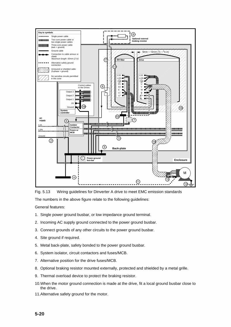
5-20
E`
D1
L1/LL2/N
RFI filter
D2
L1`L2`
Back-plate
V
+
W
U
Drive
Optional external braking resistor
L1/LL2/N
Enclosure
IsolatorContactor
AC supply
Ground
Key to symbols
Single power cable
Two-core power cable or two single power cables
Ground cable
0V
Output 3
Output 2
Output 1
Ground
System controller
Control cables to the Drives
No sensitive circuits permitted in this zone
Power-ground bus-bar
Connection to cable armour or shieldMaximum length: 50mm (2 in)
L1/L
L2/N
Armoured or shielded cable (3-phase + ground)
Alternative safety ground connection
Three-core power cable (twin + ground)
Fuses or MCB
Fig. 5.13 Wiring guidelines for Dinverter A drive to meet EMC emission standards
The numbers in the above figure relate to the following guidelines:
General features:
1. Single power ground busbar, or low impedance ground terminal.
2. Incoming AC supply ground connected to the power ground busbar.
3. Connect grounds of any other circuits to the power ground busbar.
4. Site ground if required.
5. Metal back-plate, safety bonded to the power ground busbar.
6. System isolator, circuit contactors and fuses/MCB.
7. Alternative position for the drive fuses/MCB.
8. Optional braking resistor mounted externally, protected and shielded by a metal grille.
9. Thermal overload device to protect the braking resistor.
10. When the motor ground connection is made at the drive, fit a local ground busbar close tothe drive.
11. Alternative safety ground for the motor.

5-21
12. Motor-frame ground connection, if required.
Routine EMC precautions:
13. Mount the RFI filter at the left side of the drive. Ensure a separation of 5 to 10mm (0.25to 0.375in) from the drive. Minimise the length of cables between the drive and the RFIfilter.
14. A shielded (screened) or steel wire-armoured cable must be used to connect the drive tothe motor. The shield of the cable must be connected to the motor ground terminal in thedrive by a connection no longer than 50mm (2in).
15. Connect the shield of the motor cable to the ground terminal of the motor frame using alink that is as short as possible and not exceeding 50mm (2in) in length.
16. Do not place sensitive signal circuits in a zone extending 0.3m (12in) all around the drive.
17. Unshielded wiring to the optional braking resistor(s) may be used, provided the resistor iseither in the same enclosure as the drive or the wiring does not run external to theenclosure. When the braking resistor wiring is unshielded, ensure a minimum spacing of0.3m (12in) from signal wiring and the AC supply wiring to the RFI filters.
18. If the control circuit 0V Common is to be grounded, this should be done at the hostcontroller (e.g. PLC) and not at the drive. This is to avoid injecting noise currents into the0V Common circuit.
5.4.3.1 Interruptions to the Motor Cable
The motor cable should ideally be a single piece of shielded or armoured cable having nointerruptions. In some situations it may be necessary to interrupt the cable, as in thefollowing examples:
• Connecting the motor cable to a terminal block in the drive enclosure
• Fitting a motor isolator switch for safety when work is done on the motor
In these cases the following guidelines should be followed.
Terminal block in the enclosure
The motor cable shields/armour should be bonded to the back-plate using uninsulated metalcable-clamps which should be positioned as close as possible to the terminal block. Keepthe length of power conductors to a minimum and ensure that all sensitive equipment andcircuits are at least 0.3m (12 in.) away from the terminal block.

5-22
From the Drive
To the motor
Back-plate
Enclosure
Fig. 5.14 Connecting the motor cable to a terminal block in the enclosure (Refer to Key toSymbols in Figs. 5.13)
Using a motor isolator-switch
The motor cable shields should be connected by a very short conductor having a lowinductance. The use of a flat metal coupling-bar is recommended; conventional wire is notsuitable.
The shields should be bonded directly to the coupling-bar using uninsulated metal cable-clamps. Keep the length of the exposed power conductors to a minimum and ensure that allsensitive equipment and circuits are at least 0.3m (12 in.) away.
The coupling-bar may be grounded/earthed to a known low-impedance ground/earth nearby,for example a large metallic structure which is connected closely to the drive ground.
Isolator
Coupling bar
From the Drive
To the motor
(If required)
Fig. 5.15 Connecting the motor cable to an isolating switch (Refer to Key to Symbols inFigs. 5.13)
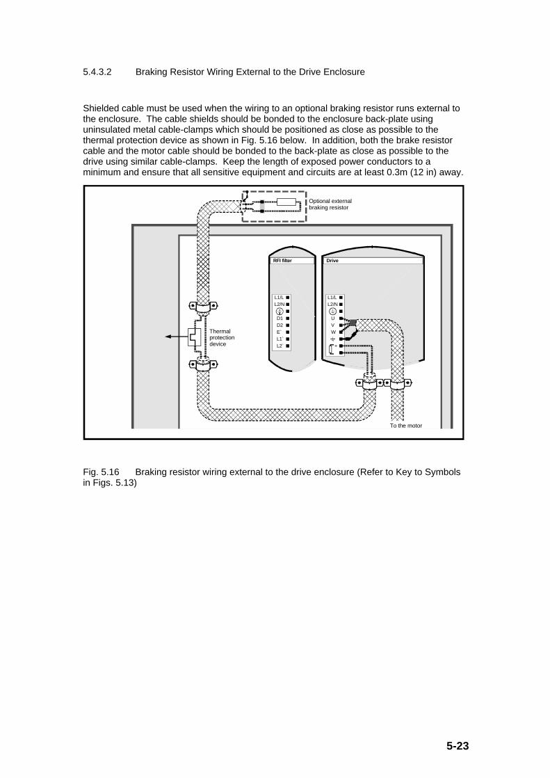
5-23
5.4.3.2 Braking Resistor Wiring External to the Drive Enclosure
Shielded cable must be used when the wiring to an optional braking resistor runs external tothe enclosure. The cable shields should be bonded to the enclosure back-plate usinguninsulated metal cable-clamps which should be positioned as close as possible to thethermal protection device as shown in Fig. 5.16 below. In addition, both the brake resistorcable and the motor cable should be bonded to the back-plate as close as possible to thedrive using similar cable-clamps. Keep the length of exposed power conductors to aminimum and ensure that all sensitive equipment and circuits are at least 0.3m (12 in) away.
E`
D1
L1/LL2/N
RFI filter
D2
L1`L2`
V
+
W
U
Drive
L1/LL2/N
Optional external braking resistor
Thermal protection device
To the motor
Fig. 5.16 Braking resistor wiring external to the drive enclosure (Refer to Key to Symbolsin Figs. 5.13)
5-24
5.5 Control Connections
Isolation of control circuits, wiring requirements
The control circuits and terminals are isolated from power circuits, but they are separated bybasic insulation only. The installer must ensure that all control circuits are separated fromhuman contact by at least one layer of insulation rated for use at the mains potential.
If the control circuits are to be connected to other circuits classified as Safety Extra LowVoltage (SELV) - for example, to a Personal Computer - a further isolating barrier must beincluded if the SELV classification is to be maintained.
There is a high resistance connection within the drive between the power and control circuits.A typical resistance is 3.3MΩ. Where testing of power circuit insulation is carried out as asafety check, this resistance value will be observed. If it is too low for a satisfactory test, thedrive input must be temporarily disconnected for the test.
Note
If the 0V Common connection is to be grounded, this should be done at the controller (e.g.PLC) not at the drive, to avoid injecting noise currents into the 0V circuit.
Using the Cable Gland Position Z (see Fig. 5.1in Section 5.2.1), the control connections arerouted through to the Control Connector positions (A1, A2, ..... A5, B1, ...... B5 and C1,.......C5).
5.5.1 Positive/Negative Digital Input Logic
The drive is supplied operational with negative logic (i.e. control inputs are active when 0Vsignals referenced to 0V Common are applied). The connection examples shown in theremainder of this Section 5.5 (and all other parts of this Guide) apply to negative logic.
To select positive logic (i.e. control inputs activated by +24VDC signals, e.g. from a higherlevel control such as a PLC) adjust the parameter #8.27 (Select digital input(B2/B3/B4/B5/C3) positive logic -see Section 9.9).
[#8.27] = 0 negative digital input logic (default as supplied)
[#8.27] = 1 positive digital input logic.
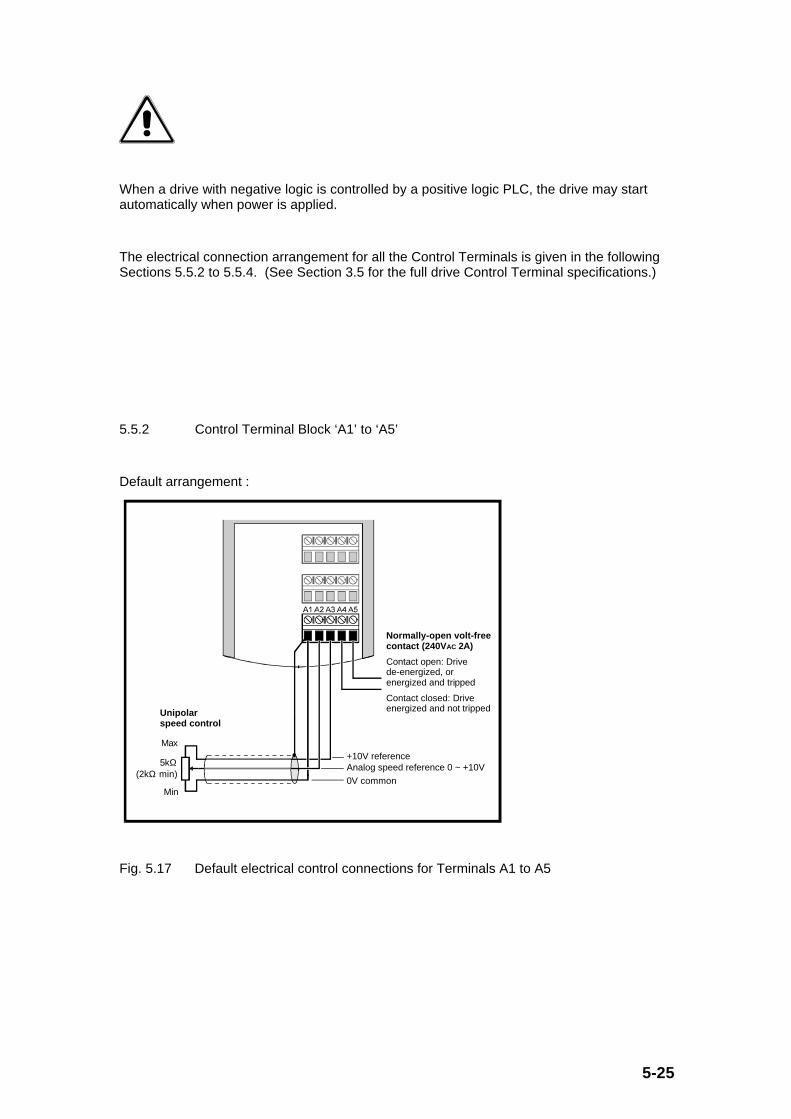
5-25
When a drive with negative logic is controlled by a positive logic PLC, the drive may startautomatically when power is applied.
The electrical connection arrangement for all the Control Terminals is given in the followingSections 5.5.2 to 5.5.4. (See Section 3.5 for the full drive Control Terminal specifications.)
5.5.2 Control Terminal Block ‘A1’ to ‘A5’
Default arrangement :
Unipolar speed control
Min0V common
Analog speed reference 0 ~ +10V+10V reference
Max
5kΩ (2kΩ min)
Normally-open volt-free contact (240V AC 2A)
Contact open: Drive de-energized, or energized and tripped
Contact closed: Drive energized and not tripped
Fig. 5.17 Default electrical control connections for Terminals A1 to A5

5-26
Control Terminal Default Configuration Optional Configurations Relevant Parameters
A1 0V Common - -
A2 0 to +10V AnalogueInput 1
(Frequency (/‘speed’)reference)
-10V to +10V AnalogueInput see Fig. 5.18
Motor Thermistor Input
see Fig. 5.19
#7.06 Analogue input1 (A2) mode selector
#7.08 Analogue input1 (A2) scale factor#7.09 Invertanalogue input 1(A2)
#7.10 Analogue input1 (A2) destinationselector
#1.10 Select bipolarfrequency reference
A3 +10V Reference - -
A4 and A5 N/O Contact indicatingDrive Healthy whencontact closed
- #8.25 Relay output(A4/A5) sourceselector
#8.26 Invert relayoutput (A4/A5)

5-27
Optional arrangements:
Speed controller(bipolar or unipolar)
0V common
Analog speed reference [−10V ~ +10V]
Optional ground connection
Fig. 5.18 Optional bipolar analogue voltage input for Terminal A2
0V common
+10V reference
Analog input
15kΩ ±10%
1 to 6 motor thermistors
Fig. 5.19 Optional motor thermistor input arrangement for Terminal A2
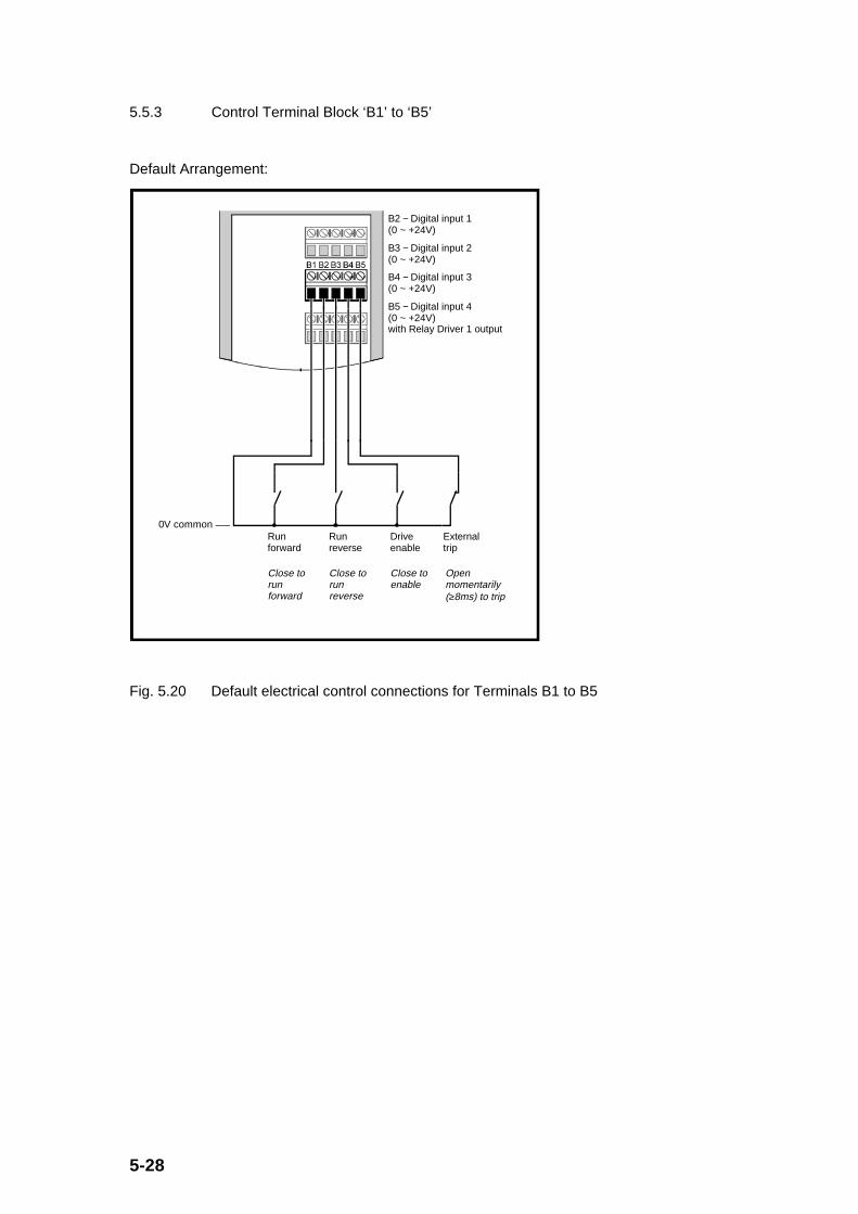
5-28
5.5.3 Control Terminal Block ‘B1’ to ‘B5’
Default Arrangement:
0V commonRun forward
Run reverse
Drive enable
External trip
Close to run forward
Close to run reverse
Close to enable
Open momentarily (≥8ms) to trip
B2 − Digital input 1 (0 ~ +24V)
B3 − Digital input 2 (0 ~ +24V)
B4 − Digital input 3 (0 ~ +24V)
B5 − Digital input 4 (0 ~ +24V) with Relay Driver 1 output
Fig. 5.20 Default electrical control connections for Terminals B1 to B5

5-29
Control Terminal Default Configuration OptionalConfigurations
Relevant Parameters
B1 0V Common - -
B2 0 to +24V Digital Input 1
(Run forward)
- #8.16 F3 input (B2)destination selector
#8.17 Invert F3 input(B2)
#8.27 Select digital inputpositive logic
B3 0 to +24V Digital Input 2
(Run reverse)
- #8.19 F4 input (B3)destination selector
#8.20 Invert F4 input(B3)
#8.27 Select digital inputpositive logic
B4 0 to +24V Digital Input 3
(Enable)
- #8.21 F5 input (B4)destination selector
#8.22 Invert F5 input(B4)
#8.27 Select digital inputpositive logic
B5 0 to +24V Digital Input 4
(External trip)
Relay Driver 1 DigitalOutput (see Fig. 5.21below)
#8.10 F1 input (B5)destination/output sourceselector
#8.11 Invert F1input/output (B5)
#8.12 Activate output 1(B5)
#8.27 Select digital inputpositive logic
Optional arrangements:

5-30
+24V (or any supply voltage less than +24V for relay coil)
Digital input 4 (0 ~ +24V) with Relay Driver 1 (or digital input 5 with Relay Driver 2)
Optional diode
I
0V common
Fig. 5.21 Optional relay driver output arrangement for Terminal B5 and C3
5.5.4 Control Terminal Block ‘C1’ to ‘C5’
Default Arrangement:
0V common
C2 − Analog output 0 ~ +10V or 0 ~ 20mA
Panel meter 0 ~ 10VZmin = 2kΩ
0V output: 0Hz output frequency
+10V output:50/60Hz output frequency
C3 − Digital input 5(0 ~ +24V)with Relay Driver 2

5-31
2.2kΩ ±10%
System controller (RS485 transceiver)
Termination resistor fitted
Termination resistor removed
Isolation unit
First or intermediate Drive on the serial link
Last Drive on the serial link
Connect an external link if no internal connection exists in the transceiver between 0V and ground
System controller (RS485 transceiver)
Connect an external link if no internal connection exists between isolated 0V and ground
Transceiver and isolation unit (if required)
Fig. 5.22 Default electrical control connections for Terminals C1 to C5
Control Terminal Default Configuration Optional Configurations Relevant Parameters
C1 0V Common - -
C2 0 to +10V AnalogueOutput 1
(Output frequency)
0 to 20mA AnalogueOutput
4 to 20mA AnalogueOutput
(circuit identical tovoltage output except use0 to 20mA full scalemeter (500Ω maximum)instead of 10V)
#7.19 Analogue output 1(C2) source selector
#7.20 Analogue output 1(C2) scale factor
#7.21 Analogue output 1(C2) mode selector

5-32
C3 0 to +24V Digital Input5
(Not used)
Relay Driver 2 DigitalOutput (see Fig. 5.21above)
#8.13 F2 input (C3)destination/output sourceselector
#8.14 Invert F2input/output (C3)
#8.15 Activate output 2(C3)
#8.27 Select digital inputpositive logic
C4 and C5 ANSI RS485 SerialComms Input/Outputwith 4800 baud
Differential CurrentInput 2
(0 to 20mA, 20 to 0mA,
4 to 20mA or 20 to4mA) (see Fig. 5.23below)
Motor Thermistor Input(see Fig. 5.24 below)
#b.23 Serial interfaceaddress
#b.26 Serial transmit delaytime (after messagereceipt)
#7.11 Analogue input 2(C4/C5) mode selector
#7.12 Analogue input 2(C4/C5) scale factor
#7.13 Invert analogueinput 2 (C4/C5)
#7.14 Analogue input 2(C4/C5) destinationselector
Note for RS485 use: The 100Ω accessible resistor can be used as the termination resistorat the far end of the RS485 link. (The resistor value can be altered if desired.) Forintermediate drives along the RS485 link, cut the 100Ω resistor out of circuit.
For good noise immune operation the RS485 lines will need suitable pull-up and pull-downresistors as shown in the above figure, at the far end of the RS485 link to force a “high” logicstate when all of the transmitters are inactive.
In summary, use only one termination resistor per RS485 link, and use only one set of 2.2kΩpull-up and pull-down resistors per 100Ω termination resistor.
Optional arrangements:

5-33
Remote analog speed control
100Ω ±1%
0~20mA current-buffer
Differential analog input(0~20mA) and RS485 input
C4/C5 terminating resistor must be fitted
Optional ground connection
Fig. 5.23 Optional differential 0 to 20mA analogue input arrangement for Terminals C4and C5
Note for Differential Current Input use: With a full scale input of 20mA, the voltage acrossC5/C4 is 2.0V with the accessible 100Ω resistor. By changing the resistor resistance, a fullscale of 2.0V can be achieved with other current levels if desired.
If the resistor is cut open-circuit, the C4/C5 input can be used as a 2.0V full scale differentialunipolar voltage input.
15kΩ ±10%
+10V reference
0V common
0~20mA analog inputRS485 input
1 to 6 motor thermistors(250Ω)
Remove the C4/C5 terminating resistor
Pull-up resistor
C4~C5 − Differential analog input (0 ~ 20mA) and RS485 input
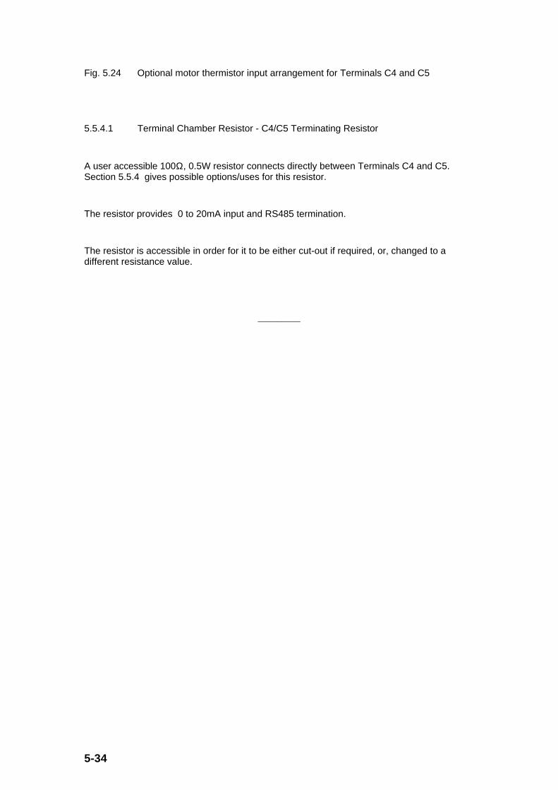
5-34
Fig. 5.24 Optional motor thermistor input arrangement for Terminals C4 and C5
5.5.4.1 Terminal Chamber Resistor - C4/C5 Terminating Resistor
A user accessible 100Ω, 0.5W resistor connects directly between Terminals C4 and C5.Section 5.5.4 gives possible options/uses for this resistor.
The resistor provides 0 to 20mA input and RS485 termination.
The resistor is accessible in order for it to be either cut-out if required, or, changed to adifferent resistance value.
_________

6-1
6.0 Operation of Display, Keypad and Parameters
6.1 Warnings
Safety of application:
Careful consideration must be given to safety aspects of the system in which the drive isincorporated.
The drive is a complex system containing many electronic components and software.Control Techniques has made every effort to minimise the failure rate and to eliminateprogramming errors. However in common with all such drives the integrity of the unit is nothigh enough to carry out safety-related functions without independent high-integrityprotection.
In any application where a drive malfunction could lead to damage or loss or injury, a riskanalysis must be carried out, and where necessary further measures taken to reduce the risk.This would normally be some form of independent safety back-up system using simpleelectro-mechanical components.
Some common examples of functions which might be safety-related are:
− Stop/start, and emergency stop
− Auto-start
− Forward/reverse
− Maximum speed
However there may be others, depending on the exact application. These will be revealed bythe risk assessment.
Warning
Some of the parameters have a profound effect on drive operation. They must not be alteredwithout careful consideration to the impact on the controlled plant, and measures must betaken to prevent unwanted changes through error or tampering.

6-2
Motor Speed/Safety
Standard squirrel-cage AC induction motors are designed as single speed motors. If it isintended to use the capability of the drive to run the motor at speeds above its designedmaximum, it is strongly recommended that the motor manufacturer is consulted first. Theprincipal risks due to overspeeding are the destruction of the rotor by centrifugal force, or ofthe bearings by vibration and overheat.
Do not rely on the maximum speed setting parameter of the drive for overspeed protection.If the possibility of overspeeding is a serious problem, other means of protection must beprovided.
Low speed operation may result in overheating of the motor because the effectiveness of theinternal cooling fan reduces with shaft speed. Motors should be equipped with thermistorprotection, and if full benefit of the use at low speeds is to be gained it may be necessary toarrange additional forced cooling for the motor.
6.2 Initial Electrical and Mechanical Set-Up
Prior to powering the drive up for the first time, ensure that Sections 4 & 5 of this manualhave been studied and the necessary recommended actions have been taken. For initialoperation and set-up of the drive, it is assumed that the connections are as shown in Fig. 6.1.

6-3
0V common
RS485 input
Run forward
Run reverse
Drive enable
External trip
Analog speed reference
Status relay contacts (250VAC, 2A N/O) (optional connection)
Optional braking resistor ≥100Ω
Optional RFI filter
AC supplyFuses and isolator
Analog frequency output signal
Digital inputs
C4/C5 terminating resistor (100Ω) across C4~C5 (0 ~ 20mA) RS485 inputs
Brake
0V common
+10V, 5mA maximum
0V common
Gland X: 3 x 2.5mm (14AWG)
Gland Y: 6 x 1.0mm (18AWG)
Gland Z: 10 x 0.5mm (20AWG)
2
2
2
Optional
Fig. 6.1 Electrical connections for initial set-up and operation
In particular:
• Check that the wiring and motor installation is correct and safe and that the motor shaft isnot exposed,.
• Check that the signal connections B2, and B3 are not connected to 0V Common (i.e. theswitches/contacts are open), and B4 and B5 are connected to 0V Common (i.e. theswitches/contacts are closed). This ensures that the motor shaft will not turn when ACpower is applied to the drive.
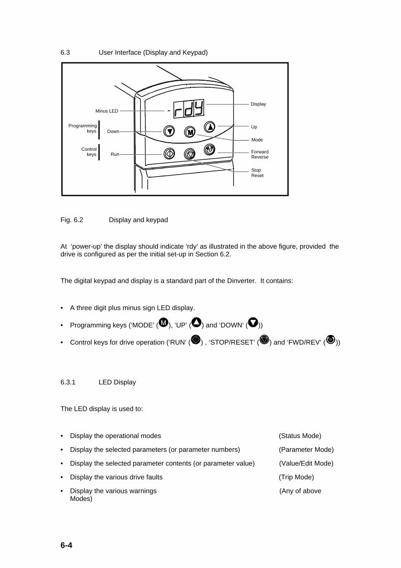
6-4
6.3 User Interface (Display and Keypad)
Minus LED
DownUp
Display
Mode
ForwardReverse
Run
Programmingkeys
Controlkeys
StopReset
Fig. 6.2 Display and keypad
At ‘power-up’ the display should indicate ‘rdy’ as illustrated in the above figure, provided thedrive is configured as per the initial set-up in Section 6.2.
The digital keypad and display is a standard part of the Dinverter. It contains:
• A three digit plus minus sign LED display.
• Programming keys (‘MODE’ ( ), ‘UP’ ( ) and ‘DOWN’ ( ))
• Control keys for drive operation (‘RUN’ ( ) , ‘STOP/RESET’ ( ) and ‘FWD/REV’ ( ))
6.3.1 LED Display
The LED display is used to:
• Display the operational modes (Status Mode)
• Display the selected parameters (or parameter numbers) (Parameter Mode)
• Display the selected parameter contents (or parameter value) (Value/Edit Mode)
• Display the various drive faults (Trip Mode)
• Display the various warnings (Any of aboveModes)
6-5
1) Status Mode
This is the normal (default) working mode of the display and indicates either the status of thedrive (e.g. ‘rdy’), warnings indicating impending trips are imminent (e.g. ‘hot’), or the value ofthe last selected parameter. (At power up the selected parameter is #0.10, (the motorfrequency (/‘speed’) in Hz).)
2) Parameter Mode
This mode is entered from the Status Mode for adjustment of the drive parameters. Thismode displays the selected parameter (and menu) number and allows the user to sequencethrough to other parameters (and menus). The Parameter Mode is indicated by a displayflashing between two numerical values (e.g. “0._ _” alternating with “_.10” for parameter#0.10 (and Menu 0)).
3) Value/Edit Mode
This mode is entered once the selected parameter number has been chosen in theParameter Mode. This mode displays the selected parameter value and allows the user tolook at and/or modify the parameter value. The Value/Edit Mode is indicated by either asteady numerical value or the right-hand digit flashing. If the value is not flashing, the valuecannot be adjusted/altered, whereas if it is flashing it can be adjusted/altered.
4) Trip Mode
This mode is automatically entered from any other display mode if the drive “trips” or shutsdown (i.e. disables the output) for whatever reason during operation. A “trip” is indicated byan alphanumeric code flashing on the display (e.g. “Et” - External trip).
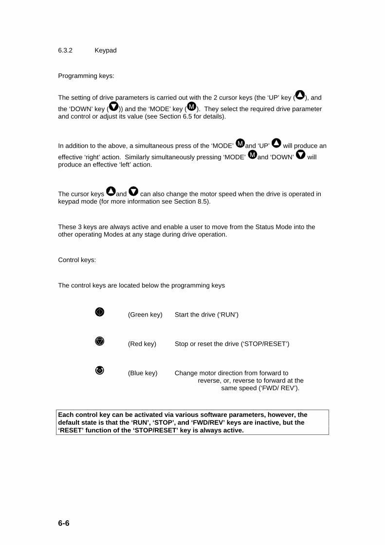
6-6
6.3.2 Keypad
Programming keys:
The setting of drive parameters is carried out with the 2 cursor keys (the ‘UP’ key ( ), and
the ‘DOWN’ key ( )) and the ‘MODE’ key ( ). They select the required drive parameterand control or adjust its value (see Section 6.5 for details).
In addition to the above, a simultaneous press of the ‘MODE’ and ‘UP’ will produce an
effective ‘right’ action. Similarly simultaneously pressing ‘MODE’ and ‘DOWN’ willproduce an effective ‘left’ action.
The cursor keys and can also change the motor speed when the drive is operated inkeypad mode (for more information see Section 8.5).
These 3 keys are always active and enable a user to move from the Status Mode into theother operating Modes at any stage during drive operation.
Control keys:
The control keys are located below the programming keys
(Green key) Start the drive (‘RUN’)
(Red key) Stop or reset the drive (‘STOP/RESET’)
(Blue key) Change motor direction from forward to reverse, or, reverse to forward at the
same speed (‘FWD/ REV’).
Each control key can be activated via various software parameters, however, thedefault state is that the ‘RUN’, ‘STOP’, and ‘FWD/REV’ keys are inactive, but the‘RESET’ function of the ‘STOP/RESET’ key is always active.

6-7
6.4 Parameter Structure
The drive parameters define the drive’s behaviour. In particular, the various parametersenable the drive to be matched to the motor and the application requirements. All settings inrelation to the behaviour of the drive are defined by these parameters. Each parameter is setto a so-called default value by the manufacturer. These default values are chosen to keep toa minimum the setting and programming required for common applications.
6.4.1 Types of Parameter
Dinverter distinguishes between two basic types of parameter; ‘numeric’ parameters and ‘bit’parameters.
Numeric Parameters are similar to a potentiometer function in that the parameter can haveany one of many values. By utilising these parameters, parameter values can be read, set orchanged.
Bit Parameters make “yes/no” decisions, or select/display one of two possibilities.
Some parameters (Numeric or Bit) display the various parameter values as text (e.g. ‘Std’)instead of the usual numerical value. These parameters are called Text Parameters. On thedisplay, Text Parameters are shown as a series of characters, but when read via the serialinterface only the parameter value is given. The series of characters, as well as theparameter values, are listed in the parameter listing in this User Guide (see Sections 7.0 and9.0).
All parameters belong to one of the following sub groups:
• Read-write parameters (RW): Values of these parameters can be changed as wellas read.
• Read-only parameters (RO): Values of these parameters can only be read, but cannot bechanged via the display and keypad or serial comms. However, these parameters can bewritten to when used as destination parameters of other internal parameters, providedthey are not protected (P type parameters).

6-8
Most parameters cause the drive operation to change immediately, so that it makes driveadjustment very easy.
Some parameters need a ‘RESET’ command before they affect drive operations. The‘RESET’ command can be done via:
parameter #A.33 (drive reset) using the input terminals,
or: serial comms,
or: the ‘STOP/RESET’ key on the keypad.
This type of parameter is signified with ‘R’ (for ‘RESET’) in the parameter listings Sections7.0 and 9.0.
Some parameters are automatically stored when the drive is disconnected from the mains.These parameters are signified with ‘S’ (for ‘SAVE’) in the parameters listings.
Finally there is the so-called “Parameter 0” (Zero) which has special functions with regard toparameter security and saving of parameter settings (see Section 6.4.3).
6.4.2 Organisation of Parameters
The number of parameters in Dinverter is quite large and as a result the flexibility of the drivesystem is quite high.
Parameters are available to configure control inputs from the terminal block, and direct theseto control operating parameters of the drive. Similarly parameters are available to takevarious internal operating parameters, and, via configurable control outputs (using otherparameters), feed these out to control outputs at the terminal block.
To reduce the risk of confusion due to the large number of parameters, they are organisedinto 14 menus or parameter groups according to their function. These 14 menus are referredto in the following text as “extended menus”.
Another “user menu”, menu 0, is introduced, to make drive use even simpler. Menu 0contains 50 parameters which are copies of parameters from the ‘extended menus’.The parameters in Menu 0 are chosen to be the parameters most often needed forusers, and therefore should be the only menu used for the majority of driveapplications. To further simplify drive operation, 20 of the 50 parameters in Menu 0are user defined in that these 20 parameters can be any parameters chosen (andtherefore copied) from the 14 extended menus. (Menu 11 defines which parametersco-exist in Menu 0 and any of the other menus.)

6-9
In summary, when the drive is in its default state, the parameters found in Menu 0 should besufficient for the drive application. Use of parameters in extended menus is only necessaryfor special applications.
Throughout the Guide all parameters are referred to as ‘#x.yz’ where ‘#x’ is the menu numberfrom 0 up to 9, A, b, c, d and E giving a total of 14 menus, and ‘yz’ is a 2 digit parameternumber in the particular menu. The value of a parameter is designated as [#x.yz].
6.4.3 “Parameter 0”
The so-called ‘Parameter 0’ has a special meaning. It is always the first parameter in eachmenu and has the parameter number ‘#x.00’ (where ‘#x’ = any menu number). It is a multi-functional parameter and does not contain any drive operating parameters.
Note that the 14 different ‘Parameter 0’ values (i.e. #x.00) are one and the same, in thatthere is only one ‘Parameter 0’ and it can be accessed in any menu as #x.00.
Parameter 0 is used for several functions:
• Memorising or saving parameter values
• Enabling access to extended menus
• Disabling access to extended menus
• Loading of default-values to all parameters
The range of the “Parameter 0” is from 0 to 999. The functions mentioned above areaccessed when “Parameter 0” has the following values:
Parameter 0 Value Description
149 Access to extended menus
900 Memorise, save or store new parameter values
(Only following a drive ‘RESET’)
544 Reset parameters to the default 60Hz settings
(Only following a drive ‘RESET’)
533 Reset parameters to the default 50Hz settings
(Only following a drive ‘RESET’)
800 Disable access to extended menus and lock user security ifset via parameter #b.30)
xyz Allow write access to all parameters (‘xyz’ is a previouslystored 3-digit user security code set in parameter #b.30)
Each function in the above table is explained in more detail in Sections 6.6 and 6.7.
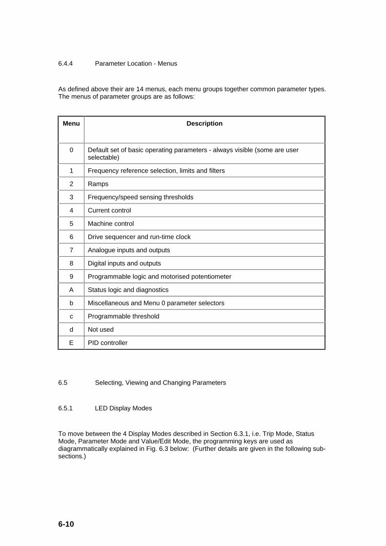
6-10
6.4.4 Parameter Location - Menus
As defined above their are 14 menus, each menu groups together common parameter types.The menus of parameter groups are as follows:
Menu Description
0 Default set of basic operating parameters - always visible (some are userselectable)
1 Frequency reference selection, limits and filters
2 Ramps
3 Frequency/speed sensing thresholds
4 Current control
5 Machine control
6 Drive sequencer and run-time clock
7 Analogue inputs and outputs
8 Digital inputs and outputs
9 Programmable logic and motorised potentiometer
A Status logic and diagnostics
b Miscellaneous and Menu 0 parameter selectors
c Programmable threshold
d Not used
E PID controller
6.5 Selecting, Viewing and Changing Parameters
6.5.1 LED Display Modes
To move between the 4 Display Modes described in Section 6.3.1, i.e. Trip Mode, StatusMode, Parameter Mode and Value/Edit Mode, the programming keys are used asdiagrammatically explained in Fig. 6.3 below: (Further details are given in the following sub-sections.)
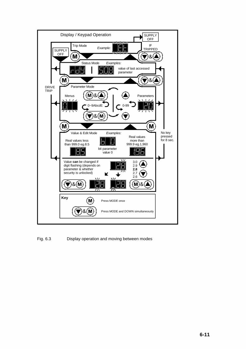
6-11
SUPPLYOFF
SUPPLYOFF
Display / Keypad Operation
Trip ModeExample:
IFTRIPPED
Status Mode Examples:
value of last accessed parameter
Parameter Mode
ParametersMenus
0-990~9AbcdE
Value & Edit Mode Examples:Real values more than
999.9 eg.1,960Real values less than 999.0 eg.8.5
bit parametervalue 0
Value can be changed ifdigit flashing (depends on parameter & whether security is unlocked)
3.02.92.82.72.6
DRIVETRIP
No key pressed for 8 sec.
Press MODE once
Press MODE and DOWN simultaneously
Key
Fig. 6.3 Display operation and moving between modes
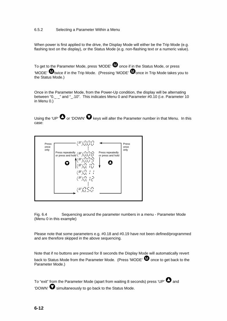
6-12
6.5.2 Selecting a Parameter Within a Menu
When power is first applied to the drive, the Display Mode will either be the Trip Mode (e.g.flashing text on the display), or the Status Mode (e.g. non-flashing text or a numeric value).
To get to the Parameter Mode, press ‘MODE’ once if in the Status Mode, or press
‘MODE’ twice if in the Trip Mode. (Pressing ‘MODE’ once in Trip Mode takes you tothe Status Mode.)
Once in the Parameter Mode, from the Power-Up condition, the display will be alternatingbetween “0._ _” and “_.10”. This indicates Menu 0 and Parameter #0.10 (i.e. Parameter 10in Menu 0.)
Using the ‘UP’ or ‘DOWN’ keys will alter the Parameter number in that Menu. In thiscase:
Press repeatedly or press and hold
Press repeatedly or press and hold
Press once only
Press once only
Fig. 6.4 Sequencing around the parameter numbers in a menu - Parameter Mode(Menu 0 in this example)
Please note that some parameters e.g. #0.18 and #0.19 have not been defined/programmedand are therefore skipped in the above sequencing.
Note that if no buttons are pressed for 8 seconds the Display Mode will automatically revert
back to Status Mode from the Parameter Mode. (Press ‘MODE’ once to get back to theParameter Mode.)
To “exit” from the Parameter Mode (apart from waiting 8 seconds) press ‘UP’ and
‘DOWN’ simultaneously to go back to the Status Mode.

6-13
6.5.3 Viewing and Changing the Selected Parameter
To view the parameter selected using the procedure in Section 6.5.2 above (e.g. #0.20),
press ‘MODE’ once when in the Parameter Mode with #0.20 selected in the display. Thedisplay will now show the value of parameter #0.20 (e.g. 0.0 (Hz)).
Depending on the type of parameter, the display could indicate the following:
• Flashing the least significant digit of a numerical value (e.g. ‘0.0’ means parameter isread/write and can be altered if required (any user security will be unlocked at this stage).
• Non-flashing numerical value (e.g. ‘0.0’ means either the parameter is read only, or, if it isread/write, security has not been unlocked).
• Flashing text (e.g. ‘ULt’ means the text parameter is read/write and can be altered ifrequired.)
• Non-flashing text (e.g. ‘ULt’ means the text parameter is read only or is read/write withsecurity set.)
• Flashing the bit value (e.g. ‘b_0’ means the bit parameter is read/write and can be alteredto 1 if required.
• Non-flashing bit value (e.g. ‘b_0’ means that either the bit parameter is read only, or, if itis read/write, security has not been unlocked.)
Provided the parameter value being viewed is flashing, the value can now be altered using
the ‘UP’ or ‘DOWN’ keys. If the display is not flashing, check whether the parameteris read only or whether security has been unlocked. (See Section 7.3 to verify the type ofparameters in Menu 0 and Section 6.7 to unlock security).
As for setting the desired/correct parameter value, the ‘UP’ or ‘DOWN’ keys caneither be pressed repeatedly or pressed and held down (only for numeric values) to alter thevalue. To speed up larger value numeric changes, the more significant digits can be
selected by pressing ‘left’ (‘DOWN’ and ‘MODE’ simultaneously), or, ‘right’ (‘MODE’
and ‘UP’ simultaneously). For example, using #0.20 which has a value of ‘0.0’ themost significant digit can be selected by the following process:
Press MODE and UP repeatedly
Press DOWN and MODE repeatedly
Fig. 6.5 Selecting the various digits of a parameter value - Value/Edit Mode (Thevalue of Parameter #0.20 in this example)
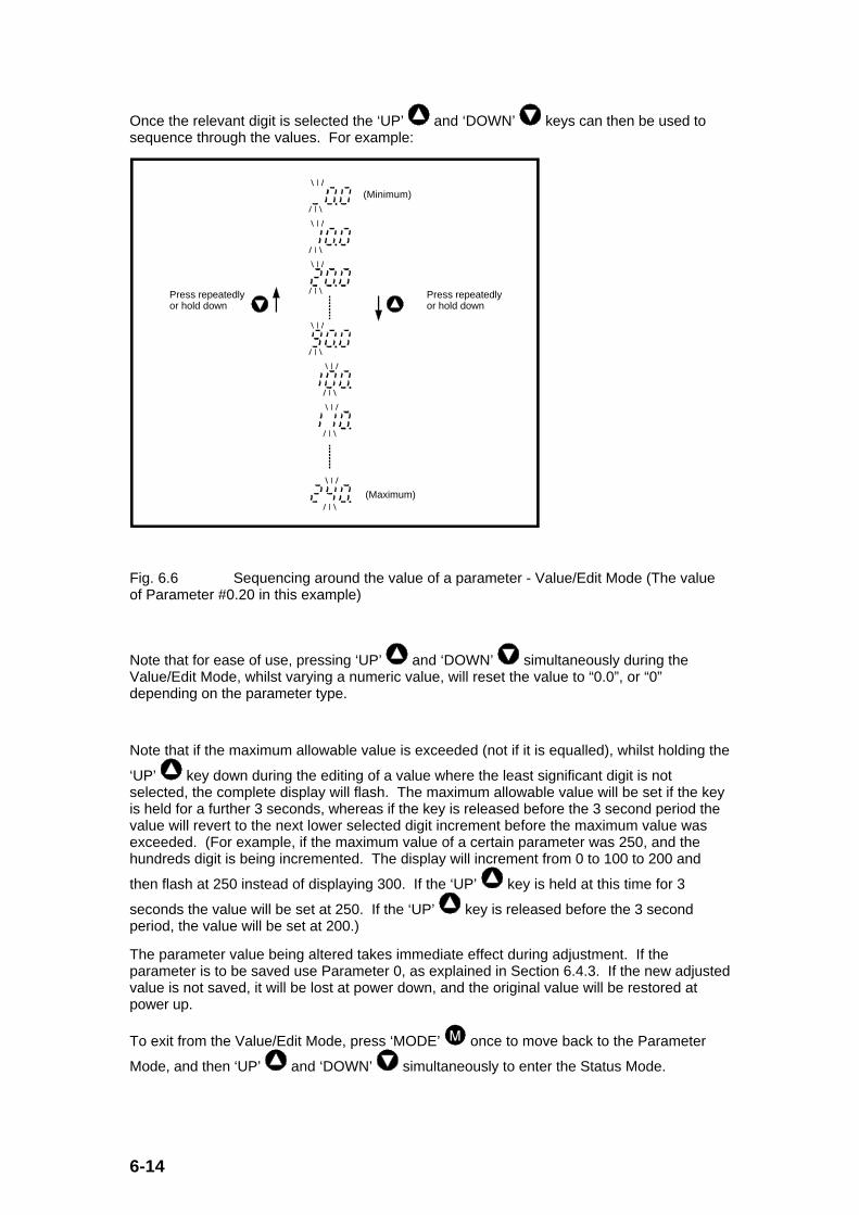
6-14
Once the relevant digit is selected the ‘UP’ and ‘DOWN’ keys can then be used tosequence through the values. For example:
(Minimum)
Press repeatedly or hold down
Press repeatedly or hold down
(Maximum)
Fig. 6.6 Sequencing around the value of a parameter - Value/Edit Mode (The valueof Parameter #0.20 in this example)
Note that for ease of use, pressing ‘UP’ and ‘DOWN’ simultaneously during theValue/Edit Mode, whilst varying a numeric value, will reset the value to “0.0”, or “0”depending on the parameter type.
Note that if the maximum allowable value is exceeded (not if it is equalled), whilst holding the
‘UP’ key down during the editing of a value where the least significant digit is notselected, the complete display will flash. The maximum allowable value will be set if the keyis held for a further 3 seconds, whereas if the key is released before the 3 second period thevalue will revert to the next lower selected digit increment before the maximum value wasexceeded. (For example, if the maximum value of a certain parameter was 250, and thehundreds digit is being incremented. The display will increment from 0 to 100 to 200 and
then flash at 250 instead of displaying 300. If the ‘UP’ key is held at this time for 3
seconds the value will be set at 250. If the ‘UP’ key is released before the 3 secondperiod, the value will be set at 200.)
The parameter value being altered takes immediate effect during adjustment. If theparameter is to be saved use Parameter 0, as explained in Section 6.4.3. If the new adjustedvalue is not saved, it will be lost at power down, and the original value will be restored atpower up.
To exit from the Value/Edit Mode, press ‘MODE’ once to move back to the Parameter
Mode, and then ‘UP’ and ‘DOWN’ simultaneously to enter the Status Mode.

6-15
6.5.4 Changing Menus
From power up, to select another Menu apart from 0, the following procedure needs to befollowed:
1) Select Parameter #0.00 (see Section 6.5.2)
2) Set value to 149 (see Section 6.5.3)
3) Enter the Parameter Mode again.
(The above 3 steps only need to be performed once after power-up).
4) Press ‘right’ (‘MODE’ and ‘UP’ simultaneously), or ‘left’ (‘DOWN’
and ‘MODE’ simultaneously) to move through the 14 menus.
Press MODE and DOWN repeatedly
Press MODE and UP repeatedly
Fig. 6.7 Sequencing around the Menus - Parameter Mode
Once the new menu has been selected, the parameter can then be selected, and then itsvalue changed as before.
Please note that the last parameter accessed in a certain Menu is the first parameter in thatMenu to be accessed upon re-entry into that Menu. This enables easy movement betweenMenus as necessary.

6-16
6.6 Storing/Restoring Parameters
6.6.1 Storing/Saving and Restoring Parameters
Most parameters will not be saved at power-down (i.e. when the drive is switched off). Thisis done to provide the facility during commissioning that if many parameters have beenadjusted (but not saved), it is a simple matter of powering off the drive and powering back upagain to restore all parameters to their original values.
To save/store parameters before the drive is powered down the following proceduremust be followed:
1) (Set all parameters to the required values.)
2) Set Parameter 0 (#x.00) to ‘900’.
3) Apply a ‘RESET’ signal, by any of the following means:
6.6.2 Resetting the Drive
The drive can be reset via any one of the following methods:
• Press the ‘STOP/RESET’ key on the drive keypad. (If the drive is in Keypad Mode
where the ‘STOP/RESET’ key is active for drive stopping, etc., and the drive is
running at the time, hold the ‘RUN’ key down whilst pressing the ‘STOP/RESET’ key to perform a ‘RESET’ instead of a ‘STOP’ action.)
• Set Parameter #A.33 (drive reset) to a 1 from 0 (via any of the Control Terminal DigitalInputs)
• Set Parameter #A.38 (user trip) to ‘100’ via serial comms.
Please note that the ‘RESET’ action is required to activate some parameter value changes(e.g. ‘Parameter 0’ is such an example as detailed in Section 6.4.3).
6-17
6.6.3 Setting Parameters to Default Values
The parameters can only be set to default values if the drive is not ‘running’.
There are 2 sets of default parameters held by the drive:
• 50Hz settings for 50Hz motors, and
• 60Hz settings for 60Hz motors.
However, the only parameters affected by the 2 different default sets are:
#0.02 (or #1.06)
#0.47 (or #5.06)
All the other default settings are the same regardless of whether they are 50Hz or 60Hzsettings.
The default values are listed in Section 7.3 for Menu 0, and Section 9 for the extendedmenus.
To set all of the parameters back to the default settings, the following procedure must befollowed: (please note that this adjusts all parameters not just ones relating to 50/60Hzoperation)
1) Set Parameter 0 (#x.00) to ‘533’ for 50Hz settings, or ‘544’ for 60Hz settings.
2) Apply a ‘RESET’ signal (as given in Section 6.6.2).
(The default values have now been entered into all parameters. These values can now beused for drive operation but most of them will be lost at power down. Therefore it is sensibleto save them by performing steps 3) and 4) below.)
3) Set Parameter 0 (#x.00) to 900.
4) Apply a ‘RESET’ signal to store the default values.

6-18
6.7 Parameter Security
The drive has 2 levels of security. This security only affects keypad access and theparameters of the drive, it does not affect parameter adjustment using serial comms. Thefirst level of security restricts access to Menu 0 (as default) only until Parameter 0 (#x.00) isset to ‘149’. Once Parameter 0 is set to ‘149’ access to all parameters in all menus isavailable. This first level of security is called ‘standard security’ and can be re-set either bypowering off the drive and re-powering up, or, setting Parameter 0 (#x.00) to ‘800’.
The second level of security is not set with default settings. However, once a user securitycode is set in Parameter #b.30 (any value from ‘1’ to ‘255’ but not equal to ‘149’), and thedrive is powered off and then on again, no parameters can be adjusted. This second levelof security is called ‘user security’. Once user security is set, all parameters can be read , butthe values cannot be altered using the keypad. (Only Menu 0 can be viewed if Parameter 0has not been set to 149).,, Once Parameter 0 (#x.00) has been set to 149 and then the UserSecurity Code value following power-up, all parameters in all menus can be viewed andchanged. If Parameter 0 is not set to 149, only Menu 0 parameters can be viewed andchanged. Setting Parameter 0 (#x.00) to ‘800’ will also re-set user security if it has beenpreviously unlocked without the need to power off the drive.
Please note that Parameter #b.30 is automatically saved at power-down and does not needstoring manually (i.e. setting Parameter #x.00 to ‘900’, etc.).
To aid in determining the security status of a drive, Parameter #0.49 has the following states:
#0.49 = ‘a b c’
where a = 0 No user security code in #b.30 saved
= 1 #b.30 has been assigned with a value other than‘149’.
b = 0 User security code has been unlocked by setting#x.00 to ‘code number’.
= 1 User security code locked (e.g. setting #x.00 to‘800’)
c = 0 Standard security has been unlocked by setting#x.00 to ‘149’.
= 1 Standard security locked (e.g. setting #x.00 to ‘800’)

6-19
The resulting value of #0.49 provides the following keypad access capability:
Value of #0.49 Access provided:
100 or 0 View and modify Menus 0 to Eparameters
101 or 1 View and modify Menu 0 parametersonly
110 only View Menus 0 to E parameters only
111 only View Menu 0 parameters only
The User Security Code enables all parameters to be “locked” so that they cannot beadjusted by unauthorised personnel.
Note: To disable the User Security Code set Parameter #b.30 to ‘149’ (once ‘149’ and theUser Security Code have been individually entered into Parameter #x.00 to allow adjustmentof Parameter #b.30).
__________

6-20

7-1
7.0 Menu 0 Parameter Descriptions
7.1 General
The 30 plus parameters contained in Menu 0 are not independent parameters, but are‘copies’ of various parameters from the extended menus. They are selected in such a way,that most of the applications can be implemented using only the parameters in Menu 0,without needing to use the extended menus.
Some parameters in Menu 0 can be selected/chosen by the user (using Menu b), whilst theremainder cannot be re-assigned to other extended menu parameters. Menu 0 parametersare defined as follows:
#0.01 to #0.10, and #0.31 to #0.50: Pre-defined parameters which cannot bere-assigned.
#0.11 to #0.30 : User defined parameters, determined byparameters #b.01 to #b.20.
There are different parameter types that are used in the parameter descriptions that follow inSection 7.3.
List of parameter types:
RW Read/WriteRead/ write parameter. (Parameters that can be set (written) by theuser, as well as read.)
RO Read Only Read only parameter for displaying operating modes and parameter values. (Parameters that can be read by the userbut not set by the user, although the internal drive software has read/write access to them, for example RO parameters can be destinations of digital inputs.)
Bit Bit Bit parameter, can exist in only 2 states, 0 or 1.
B Bipolar Bipolar parameter, can have positive or negative values.
U Unipolar Unipolar parameter, can have only positive values.
T Text Parameter has different options. Options are specified via text (or character string).
R Reset Parameter needs a RESET signal to implement value changes. (See Section 6.6.2)
S Saved Parameter is saved automatically by mains switch off.
P Protected Parameter cannot be used as a destination of programmableinputs and functions.
F Fixed Parameter in Menu 0 that cannot be re-assigned.
C Custom Parameter in Menu 0 than can be customer/user assigned.
The following sections give a quick reference list of the Menu 0 parameters, and an in-depthdescription of each parameter.

7-2
7.2 Menu 0 logic block diagram - Default settings
The figure below illustrates the structure and function of the drive with default parameters setand how the various Menu 0 parameters are interlinked. It will be noted that all relevantparameters in the Menu 0 block diagram are indicated as ‘0.xy’ (whereas in the text they areindicated as #0.xy) and related parameters indicated as ‘x. yz’.
A2
0.24Analog input 1 mode selector
Analog input 1(0 ~ +10V)
0.25Analog input 2 mode selector
C4
C5 0.14
Jog frequency reference
0.16
Stop mode selector
B2
B3
Run forward
Run reverse
B4
Drive enable
B5
External trip
Sequencer
x(-1)
0.01
Minimum frequency
0.02
Maximum frequency
Control and monitoring
0.37 Serial interface address
General parameters
0.38Initial parameter displayed selector
0.20 Skip frequency 1
0.21 Skip frequency band 1
0.22 Skip frequency 2
0.23 Skip frequency band 2
0.11Pre-ramp frequency reference
0.15Deceleration mode selector
Ramps
0.17Select torque control
0.03 Acceleration rate
0.04 Deceleration rate
0.45 Motor − rated full-load slip(RPM)
0.47 Motor − rated frequency
0.46 Motor − rated current
Slip compensation
0.09 Select dynamic V/f
0.08 Boost voltage
0.44 Motor − rated voltage
0.10
Motor frequency
5.02
Motor voltage
5.04
Speed (RPM)
0.12
Post-ramp frequency reference
0.06
Current limit
0.13
Load-current real/active component
Current measurement
RS485
1.01Selected final frequency reference
1.13
Jog selected
1.12
Reverse selected
1.11
Final frequency reference on
0Hz
0.49 Security status
0.50Software version
Voltage calculations
0.41 PWM switching frequency
0.42 Motor − number of poles
0.43 Motor − power factor
0.07 Select boost mode
1.02Pre-skip frequency reference
Fig. 7.1 Menu 0 parameter block diagram

7-3
7.3 Menu 0 Parameter List
Parameter
Equivalent
No.: to: Type Description
Range/Mode
Note: ‘Std ( 0) ...’ where ‘Std’is actual display value and ‘0’is value used by RS485 serial
communications.
Default Customer
Setting:
#0.00 #x.00 RW, U, R, P, F Security and
parameter
storage
0 to 999 (See Section 6.4.3) 0
#0.01 #1.07 RW, B, F Minimum
frequency
0.0 to [#0.02] or -0.0 to -[ULF] 0.0Hz
#0.02 #1.06 RW, U, F Maximum
frequency
0.0 to ULF, where:
ULF = 240Hz when #0.41 = 3
(kHz),
ULF = 480Hz when #0.41 = 6
(kHz),
ULF = 720Hz when #0.41 = 9
(kHz),
ULF = 960Hz when #0.41 = 12
(kHz)
50.0 or
60.0
Hz
#0.03 #2.11 RW, U, F Acceleration
rate
0.0 to 999.0s per 100Hz 5.0s/100
Hz
#0.04 #2.21 RW, U, F Deceleration
rate
0.0 to 999.0s per 100Hz 10.0s/10
0Hz
#0.05 #1.14 RW, U, P, F Frequency
reference
selector
0 = Selection via digital inputs
1 = Analogue reference 1
2 = Analogue reference 2
3 = Preset reference
4 = Keypad reference
5 = Precision reference
0

7-4
#0.06 #4.07 RW, U, F Current limit 0.0 to 150% x FLC/[#0.46],
where:
FLC = 4.3A for
DIN1220075A,
FLC = 3.0A for
DIN1220055A,
FLC = 2.3A for
DIN1220037A,
FLC = 1.5A for
DIN1220025A.
150%
#0.07 #5.14 RW, Bit, P, F Select boost
mode
0 = Fixed boost
1 = Auto boost
1
#0.08 #5.15 RW, U, F Boost
voltage
0.0 to 25.5% rated motor
voltage
10.0%
#0.09 #5.13 RW, Bit, F Select
dynamic V/f
0 = Fixed V/f (Constant torque
loads)
1 = Dynamic V/f (Fan/pump
loads)
0
#0.10 #5.01 RO, B, P, F Motor
frequency
0.0 to ≈ ±[#0.02] Hz
#0.11 #1.03 RO, B, P, C Pre-ramp
frequency
reference
+[#0.02] Hz
#0.12 #2.01 RO, B, P, C Post-ramp
frequency
reference
≈ +[#0.02] Hz
#0.13 #4.02 RO, B, P, C Load current
(real/active
component)
0.0 to +[#0.43] x FLC x 1.5
A, where:
FLC = 4.3A for
DIN1220075A,
FLC = 3.0A for
DIN1220055A,
FLC = 2.3A for
DIN1220037A,
FLC = 1.5A for
DIN1220025A.

7-5
#0.14 #1.05 RW, U, C Jog
frequency
reference
0.0 to 400Hz 1.5Hz
#0.15 #2.04 RW, U , T, P, C Deceleration
mode
selector
Std (0) = decel with ramp hold
FSt (1) = no ramp hold
Std (0)
#0.16 #6.01 RW, U, T, P, C Stop mode
selector
CSt (0) = Coast
rP (1) = Ramp
rP.I (2) = Ramp + 1s DC
dcI (3) = Timed DC
rP (1)
#0.17 #4.11 RW, Bit, C Select torque
control
0 = Frequency control
1 = Torque control
0
#0.18 - C Not
programmed
Defined via #b.08
#0.19 - C Not
programmed
Defined via #b.09
#0.20 #1.29 RW, U, C Skip
frequency 1
0.0 to ULF Hz (see #0.02
above)
0.0Hz
#0.21 #1.30 RW, U, C Skip
frequency
band 1
0.0 to 5.0Hz 0.5Hz
#0.22 #1.31 RW, U, C Skip
frequency 2
0.0 to ULF Hz (see #0.02
above)
0.0Hz
#0.23 #1.32 RW, U, C Skip
frequency
band 2
0.0 to 5.0Hz 0.5Hz
#0.24 #7.06 RW, U, T, P, C Analogue
input 1 (A2)
mode
selector
ULt (0) = -10V to +10V
input
th (1) = Thermistor input
ULt (0)

7-6
#0.25 #7.11 RW, U, T, P, C Analogue
input 2
(C4/C5)
mode
selector
ANS (0) = ANSI comms port
active
0.20 (1) = 0 to 20mA input
20.0 (2) = 20 to 0mA input
4.20 (3) = 4 to 20mA input
20.4 (4) = 20 to 4mA input
th (5) = Thermistor input
ANS (0)
#0.26 - C Not
programmed
Defined via #b.16
#0.27 - C Not
programmed
Defined via #b.17
#0.28 - C Not
programmed
Defined via #b.18
#0.29 - C Not
programmed
Defined via #b.19
#0.30 - C Not
programmed
Defined via #b.20, (#0.30
scaled via #b.21)
#0.31
to
#0.36
- F Reserved for
other drive
parameters
-
#0.37 #b.23 RW, U, P, F Serial
interface
address
0.0 to 9.9 (i.e. Group.Unit) 1.1
#0.38 #b.22 RW, U, F Initial
parameter
displayed
selector
0 to 50 (i.e. #0.00 to #0.50) 10
(i.e.#0.1
0)
#0.39
and
#0.40
- F Reserved for
other drive
parameters
-
#0.41 #5.18 RW, U, T, P, F PWM
switching
frequency
3 (kHz) (0), 6 (kHz) (1),
9 (kHz) (2), or, 12 (kHz) (3)
3 (kHz)
(0)
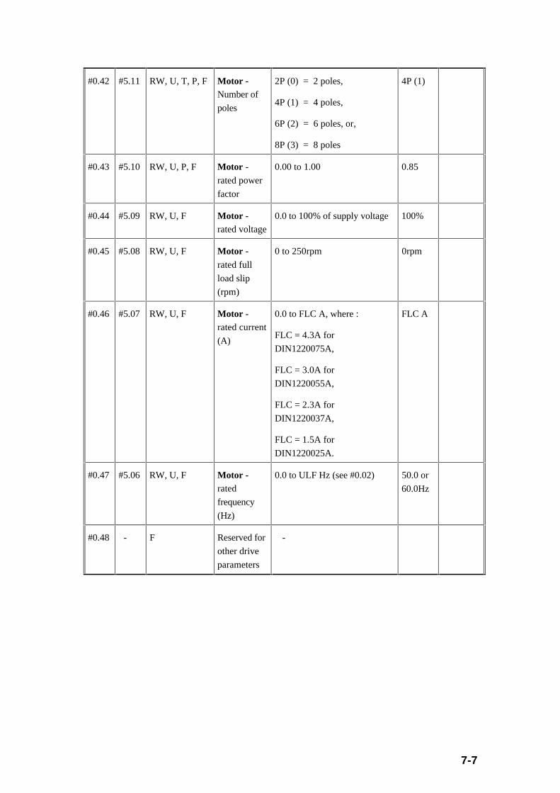
7-7
#0.42 #5.11 RW, U, T, P, FMotor -Number of
poles
2P (0) = 2 poles,
4P (1) = 4 poles,
6P (2) = 6 poles, or,
8P (3) = 8 poles
4P (1)
#0.43 #5.10 RW, U, P, F Motor -
rated power
factor
0.00 to 1.00 0.85
#0.44 #5.09 RW, U, F Motor -rated voltage
0.0 to 100% of supply voltage 100%
#0.45 #5.08 RW, U, F Motor -rated full
load slip
(rpm)
0 to 250rpm 0rpm
#0.46 #5.07 RW, U, F Motor -rated current
(A)
0.0 to FLC A, where :
FLC = 4.3A for
DIN1220075A,
FLC = 3.0A for
DIN1220055A,
FLC = 2.3A for
DIN1220037A,
FLC = 1.5A for
DIN1220025A.
FLC A
#0.47 #5.06 RW, U, F Motor -rated
frequency
(Hz)
0.0 to ULF Hz (see #0.02) 50.0 or
60.0Hz
#0.48 - F Reserved for
other drive
parameters
-

7-8
#0.49 - RO, U, P, F Security
status
‘a b c’ where:
a = 0 = No user security code
in #b.30
= 1 = User security code set
in #b.30
b = 0 = Security code
unlocked/inactive
= 1 = Security code locked
c = 0 = #x.00 set to 149
= 1 = #x.00 not set to 149
(00)1
#0.50 #b.29 RO, U, P, F Software
version
1.00 to 9.99 e.g.1.03
or latest
version

7-9
7.4 Menu 0 Parameter Descriptions
#0.00 Parameter 0
Parameter type: RW, U, R, P, F
Corresponds with: #x.00 (where x = any menu number from 0 to 9, A, b, c, dand E).
Adjustment range: 0 to 999
Units: -
Default value: 0
Related parameters: #b.30
The critical values are: (see Section 6.4.3 for more details)
149 - Allow access to extended menus
533 - Reset parameters to 50Hz default settings (only after a drive‘RESET’)
544 - Reset parameters to 60Hz default settings (only after a drive‘RESET’)
800 - Disable access to extended menus and lock user security ifset via parameter #b.30)
900 - Memorise or store new parameter values (only after a drive‘RESET’)
xyz - Allow write access to all parameters (where xyz = apreviously stored user security code set in#b.30)

7-10
#0.01 Minimum frequency (fMin )
Parameter type: RW, B, F
Corresponds with: #1.07
Adjustment range: 0.0 to fMax (#0.02) (when [#1.08] = 0),
or, -0.0 to - (ULF) (when [#1.08] = 1),, where
ULF = 240Hz when #0.41 = 3 (kHz),
ULF = 480Hz when #0.41 = 6 (kHz),
ULF = 720Hz when #0.41 = 9 (kHz),
ULF = 960Hz when #0.41 = 12 (kHz)
Units: Hz
Default value: 0.0
Related parameters: #0.02, #0.41, #1.08, #1.10
This parameter sets the given minimum frequency and depends on the settings of#1.08 and #1.10, where #1.08 is the select negative minimum frequency, and #1.10is the select bipolar frequency reference.
With default settings of #1.08 and #1.10 (both set to 0), the adjustment range is 0.0to [#0.02], and defines the minimum frequency for both forward and reverseoperation. If #0.02 is set less than #0.01, then #0.01 will be overwritten with theminimum set value of #0.02.
If #1.10 equals 1 (bipolar frequency reference selected), parameter #0.01 is ignored,i.e. the minimum frequency is always 0.0Hz regardless of what is set in #0.01.
If #1.08 equals 1 (negative minimum frequency selected) the adjustment rangebecomes -0.0Hz to - (ULF) Hz, and defines a minimum frequency when operating inreverse only, i.e. [#0.01] (a negative value) ≤ (frequency demand) ≤ +[#0.02].
Whilst jogging, the minimum frequency has no effect, except if #1.08 equals 1.
Note that if #0.02 (the maximum frequency) is set less than the value of #0.01, then[#0.01] will automatically be set to the value of #0.02.
Note that this parameter cannot be adjusted when the drive is enabled.

7-11
#0.02 Maximum frequency (f Max)
Parameter type: RW, U, F
Corresponds with: #1.06
Adjustment range: 0.0 to ULF where:
ULF = 240Hz when #0.41 = 3 (kHz),
ULF = 480Hz when #0.41 = 6 (kHz),
ULF = 720Hz when #0.41 = 9 (kHz),
ULF = 960Hz when #0.41 = 12 (kHz)
Units: Hz
Default value: 50.0 (when #x.00 set to 533 followed by a ‘RESET’), or
60.0 (when #x.00 set to 544 followed by a ‘RESET’).
Related parameters: #0.01, #0.41, #1.08
This parameter sets the given maximum frequency and depends on the setting of#1.08. Please note that slip compensation (#0.45) and current limit can increase themotor frequency above the maximum frequency set.
With a default setting of #1.08 (set to 0, i.e. negative minimum frequency notselected), this parameter defines the maximum frequency for both forward andreverse operation.
If [#1.08] equals 1 (negative minimum frequency selected), this parameter definesthe maximum frequency during forward operation only.
Note that if [#0.02] is set less than the value in #0.01 (the minimum frequency), then[#0.01] will automatically be set to the value of #0.02.
Note that this parameter cannot be adjusted when the drive is enabled.

7-12
#0.03 Acceleration rate (actually Accel 1/forward accel 1 rate)
Parameter type: RW, U, F
Corresponds with: #2.11
Adjustment range: 0.0 to 999.0
Units: s/100Hz
Default value: 5.0
Related parameters: #2.09
The acceleration rate corresponds to the time to accelerate from 0 to 100Hz. Theacceleration rate is effective for frequency increases in the forward or reversedirections, unless parameter #2.09 (enable reverse accel/decel) has been set to a 1,whereupon this parameter is only effective for forward acceleration (#2.15 iseffective for reverse acceleration).
#0.04 Deceleration rate (actually Decel 1/forward decel 1 rate)
Parameter type: RW, U, F
Corresponds with: #2.21
Adjustment range: 0.0 to 999.0
Units: s/100Hz
Default value: 10.0
Related parameters: #2.09
The deceleration rate corresponds to the time to decelerate from 100Hz to 0Hz. Thedeceleration rate is effective for frequency decreases in the forward or reversedirections, unless parameter #2.09 (enable reverse accel/decel) has been set to a 1,whereupon this parameter is only effective for forward deceleration (#2.25 iseffective for reverse deceleration)..
7-13
#0.05 Frequency reference selector
Parameter type: RW, U, P, F
Corresponds with: #1.14
Adjustment range: 0 to 5
Units: -
Default value: 0
Related parameters: #1.41, #1.42, #1.43, #1.44, #1.49
This parameter selects the source of the frequency reference value. It has six options:
0 : Selection via digital inputs (in particular bit parameters #1.41 to #1.44)
1 : Analogue reference 1
2 : Analogue reference 2
3 : Preset reference
4 : Keypad reference
5 : Precision reference
When [#0.05] is set to 0 the reference selected depends on the state of bitparameters #1.41 to #1.44 as follows: (where x = don’t care either 0 or 1)
[#1.41] -Select
analoguefrequencyreference 2
[#1.42] -Selectpreset
frequencyreference
[#1.43] -Selectkeypad
frequencyreference
[#1.44] -Select
precisionfrequencyreference
Frequency ReferenceSelected
SelectedFrequencyReferenceParameter([#1.49])
0 0 0 0 Analogue reference 1 1
1 0 0 0 Analogue reference 2 2
x 1 0 0 Preset reference 3
x x 1 0 Keypad reference 4
x x x 1 Precision reference 5
The bits #1.41 to #1.44 are provided to allow control by digital inputs such thatfrequency references can be selected by external control such as digital inputs.

7-14
#0.06 Current limit
Parameter type: RW, U, F
Corresponds with: #4.07
Adjustment range: 0 to 150% x (rated drive current [FLC])/(rated motor current[#0.46]), where: FLC = 4.3A for DIN1220075A,
FLC = 3.0A for DIN1220055A,
FLC = 2.3A for DIN1220037A,
FLC = 1.5A for DIN1220025A.
Units: % of rated real/active (or power component of)current
Default value: 150
Related parameters: #0.17, #0.46, #4.13, #4.14, #b.32
If the rated motor current ([#0.46]) is set to a value less than the drive rated current(FLC or [#b.32]), it is possible to have a current limit set above 150%.
The current limit (for both motoring and regenerating) is active in both forward andreverse directions. However, it has no effect until the measured active currentapproaches, and tries to exceed the current limit value. (This only applies if #0.17 isset to 0 (default), frequency (/’speed’) control.)
When the motoring current limit is reached, the acceleration ramp is stopped or thedrive frequency is decreased via PI (proportional/integral) control (#4.13, #4.14).
Similarly, when the braking, regenerative current limit is reached, the decelerationramp is stopped or the drive speed is increased via PI control (#4.13, #4.14).
In the torque control mode ([#0.17] = 1), the current limit is effective at all times, andadjusts the frequency to try and maintain the active measured current at the currentdemand level/value (i.e. the current limit).
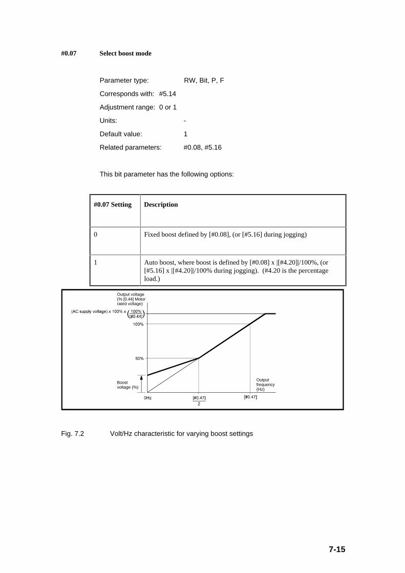
7-15
#0.07 Select boost mode
Parameter type: RW, Bit, P, F
Corresponds with: #5.14
Adjustment range: 0 or 1
Units: -
Default value: 1
Related parameters: #0.08, #5.16
This bit parameter has the following options:
#0.07 Setting Description
0 Fixed boost defined by [#0.08], (or [#5.16] during jogging)
1 Auto boost, where boost is defined by [#0.08] x |[#4.20]|/100%, (or[#5.16] x |[#4.20]|/100% during jogging). (#4.20 is the percentageload.)
Output voltage(% [0.44] Motor rated voltage)
Boost voltage (%)
Output frequency (Hz)
Fig. 7.2 Volt/Hz characteristic for varying boost settings

7-16
#0.08 Boost voltage
Parameter type: RW, U, F
Corresponds with: #5.15
Adjustment range: 0.0 to 25.5
Units: % of motor rated voltage (#0.44)
Default value: 10.0
Related parameters: #0.07, #0.44, #5.16
The boost voltage defines the motor voltage, and thus the flux and torque developedat low speed (defined by #5.16 when jogging). It is only effective from 0Hz up to50% of motor rated frequency (50% of [#0.47]). See Fig. 7.2 in the #0.07 descriptionabove.
The actual boost voltage (in volts) is: (use [#5.16] instead of [#0.08] for jog boostvoltage)
[#0.08]/100% x [#0.44]/100% x (input supply voltage)
where: #0.44 is the Motor - rated voltage
Set up recommendation: With the drive running, enter a small frequencyreference (e.g. 2-3 Hz). If the motor does not rotate, the value of #0.08 should beincreased until the motor turns. When the motor is turning, set up the parameter sothat the motor current is minimal.

7-17
#0.09 Select dynamic V/f
Parameter type: RW, Bit, F
Corresponds with: #5.13
Adjustment range: 0 or 1
Units: -
Default value: 0
Related parameters: #0.07, #0.47
This bit parameter has the following options:
#0.09 Setting Description
0 Fixed linear V/f characteristic for constant load/torque applications
1 Dynamic V/f characteristic for fan/pump applications. Advantagesinclude energy saving and less motor audible noise.
The two V/f characteristics are illustrated in Fig. 7.3 below:
Output voltage (V)
Output frequency (Hz)
AC supply voltage
Increasing load(ie. |[4.20]| > 0%
or
Fig. 7.3 Volt/Hz characteristic for fixed and dynamic V/f settings
If [#0.09] equals 1 (dynamic V/f), and, 0% ≤ [#4.20] ≤ 70%, then the effective V/fpoint (i.e. output frequency when 100% of #0.44 voltage is reached) is:
Effective V/f point (in Hz) = [#0.47] x 0.5 + [#4.20]/ (2 x 70%)
where: #0.47 is the Motor - rated frequency
#4.20 is the percentage load
Otherwise if: |[#4.20]| ≥ 70%)
Then: Effective V/f point = [#0.47]

7-18
#0.10 Motor frequency
Parameter type: RO, B, P, F
Corresponds with: #5.01
Range: 0.0 to approx. ±[#0.02]
Units: Hz
Related parameters: #0.12
This parameter gives the output frequency of the drive. The value is calculated asfollows: (i.e. the post-ramp reference plus the slip compensation term)
[#0.10] = [#0.12] + [#0.45] x ([#0.42]/120) x ([#4.20]/100%)
where: #0.12 is the post-ramp frequency reference
#0.42 is the Motor - number of poles (use values of 2, 4, 6 or 8)
#0.45 is the Motor - rated full load slip (rpm)
#4.20 is the percentage load
Therefore the range of this parameter (#0.10) is the maximum magnitude ofparameters #0.01 and #0.02 plus whatever is added or subtracted for the slipcompensation.
#0.11 Pre-ramp frequency reference
Parameter type: RO, B, P, C
Corresponds with: #1.03
Range: 0.0 to ±fMax[#0.02], (or, [#0.01] to [#0.02], if [#1.08]= 1)
Units: Hz
Related parameters: -
This is the frequency reference prior to the accel/decel rates being applied. It isuseful for drive set-up and fault finding.

7-19
#0.12 Post-ramp frequency reference
Parameter type: RO, B, P, C
Corresponds with: #2.01
Range: 0.0 to ±fMax[#0.02], (or, [#0.01] to [#0.02], if [#1.08]= 1)
Units: Hz
Related parameters: -
This is the frequency reference after the accel/decel rates have been applied. It isuseful for drive set-up and fault finding. This value can be increased above therange indicated by current limit.
#0.13 Load current (real/active component)
Parameter type: RO, B, P, C
Corresponds with: #4.02
Range: 0.0 to + [#0.43] x FLC x 1.5 where FLC = [#b.32]and
FLC = 4.3A for DIN1220075A,
FLC = 3.0A for DIN1220055A,
FLC = 2.3A for DIN1220037A,
FLC = 1.5A for DIN1220025A,
Units: A
Related parameters: #0.43, #0.46, #b.32
This parameter displays the ‘torque producing’ current or load.
In a range between 15Hz and rated motor frequency ([#0.47]), the load current isnearly proportional to the given torque (T), i.e.
T ~ [#0.13]
In the field-weakening region above motor rated frequency, torque decreasesinversely proportional to speed at the same active current, i.e. the followingrelationship applies:
T ~ [#0.13] x (motor rated frequency [#0.47])/(motor frequency [#0.10])

7-20
#0.14 Jog frequency reference
Parameter type: RW, U, C
Corresponds with: #1.05
Adjustment range: 0.0 to 400.0, (limited to 240.0 by #0.02 when [#0.41] = 3(kHz))
Units: Hz
Default value: 1.5
Related parameters: #1.13
This parameter defines the frequency reference for jogging.
If a value is set which is higher than the ULF (upper limit frequency) then the actualjog reference will be limited to the ULF value. Similarly the jog reference will belimited to the maximum frequency #0.02 even though the set value could be higherthan this.
#0.15 Deceleration mode selector
Parameter type: RW, U, T, P, C
Corresponds with: #2.04
Adjustment range: Std (0) or FSt (1)
Units: -
Default value: Std (0)
Related parameters: #0.04
This parameter has 2 settings: #0.15 Setting
(Display)
Setting via
Serial
comms
Description
Std 0 Deceleration ramp held whenever braking IGBT
‘on’ - Standard ramp
FSt 1 Deceleration ramp unaffected by braking IGBT -
Fast ramp
7-21
In the ‘Std’ mode of operation, during deceleration, if the DC link voltage reaches thelimit where the internal braking transistor is turned ‘on’, the deceleration ramp ishalted. When the DC link voltage decreases below this value, and the internalbraking transistor is turned ‘off’, the deceleration ramp is continued. The frequencyreduces in a staircase fashion.
Advantages of ‘Std’ mode: With the simplest set up, the risk of overvoltage tripsduring deceleration is minimised when no braking resistor is connected.
In the ‘FSt’ mode of operation, during deceleration, the ramp rate is maintainedregardless of whether the internal braking transistor is ‘on’ or ‘off’(subject to thecurrent limits programmed). This setting is recommended when using a suitablebraking resistor.
#0.16 Stop mode selector
Parameter type: RW, U, T, P, C
Corresponds with: #6.01
Adjustment range: CSt (0), rP (1), rP.I (2), or, dcI (3)
Units: -
Default value: rP (1)
Related parameters: #1.11, #6.06, #6.07
This parameter has 4 settings:
#0.16 Setting
(Display)
Setting via
Serial
comms
Description
CSt 0 Coast stop
rP 1 Ramp stop
rP.I 2 Ramp stop with 1 second DC injection
dcI 3 Timed DC injection braking stop
In the ‘CSt’ stopping mode, after applying a stop command, the output stage isdisabled immediately; the drive coasts to a standstill. The drive is disabled for aminimum of 1 second before it can be enabled again.

7-22
In the ‘rP’ stopping mode, after applying a stop command, the drive ramps down tozero frequency according to the deceleration rate. The output stage is disabled onesecond after reaching 0Hz. With large inertia motor loads, the motor can still berunning at low speed after this time, depending on the boost settings.
In the ‘rP.I’ stopping mode, after applying a stop command, the drive ramps down tozero frequency according to the deceleration rate. On reaching 0Hz, a DC voltage isswitched onto the motor for one second (value set via #6.06), which creates aholding torque. With large inertia motor loads, #6.06 can be set to ensure that themotor is stationary after the 1 second DC injection period.
In the ‘dcI’ stopping mode, DC injection starts immediately after a stop command isgiven. The DC injection voltage is set via #6.06, and the DC injection time is setwith #6.07.
#0.17 Select torque control
Parameter type: RW, Bit, C
Corresponds with: #4.11
Adjustment range: 0 or 1
Units: -
Default value: 0
Related parameters: #0.06, #4.03, #4.04
The bit parameter has the following settings::
#0.17 Setting Description
0 Frequency control (with PI current limit control inactive until currentlimit (i.e. [#0.06]) reached)
1 Torque control (PI current limit control always active to maintaincurrent at demand value i.e. [#4.04])
When the drive is operated in the torque control mode, and the torque (or currentdemand) is higher than the load torque (or measured active current), the drive isaccelerated to 20% above the maximum frequency [#0.02], but limited by ULF. Thedrive direction is controlled by the required torque polarity as follows:
7-23
Torque (load) polarity Frequency polarity Direction/Power flow
Positive Positive Forward (+ve)/ Motoring
Positive Negative Reverse (-ve)/ Regenerating
Negative Positive Forward (+ve)/ Regenerating
Negative Negative Reverse (-ve)/ Motoring
#0.18 Not programmed
#0.19
Parameter type: C
Defined via: #b.08 (for #0.18)
#b.09 (for #0.19)
#0.20
#0.21
#0.22
#0.23
#0.20 Skip frequency 1
#0.22 Skip frequency 2
Parameter type: RW, U, C
Corresponds with: #1.29 (skip frequency 1)
#1.31 (skip frequency 2)
Adjustment range: 0.0 to ULF
Units: Hz
Default value: 0.0
Related parameters: #0.21, #0.23
These 2 skip frequencies are available to prevent mechanical resonances in asystem, by ensuring that certain frequencies can be avoided by always rampingthrough them.
Setting either skip frequency to a value of 0.0Hz (as default) makes the relevantskip frequency ineffective.
See the graph below (Fig. 7.4) illustrating the action of skip frequencies andassociated skip frequency bands.

7-24
#0.21 Skip frequency band 1
#0.23 Skip frequency band 2
Parameter type: RW, U, C
Corresponds with: #1.30 (skip frequency band 1)
#1.32 (skip frequency band 2)
Adjustment range: 0.0 to 5.0
Units: Hz
Default value: 0.5
Related parameters: #0.20, #0.22
These parameters allow frequency bands to be skipped in order to avoid mechanicalresonances.
Frequency skipping occurs around each skip frequency (#0.20 and #0.22), andincludes the skip frequency bands (#0.21 and #0.23) above and below the relatedskip frequency. Therefore, the frequency range over which the skip function iseffective is twice the value of the appropriate skip frequency band.
The drive accelerates/decelerates through the selected skip frequency areas, withoutstopping.
[#0.11]Pre-ramp frequency reference
[#1.02]Pre-filter frequency reference
Fig. 7.4 Typical examples showing operation of skip frequencies and bands

7-25
#0.24 Analogue input 1 (A2) mode selector
Parameter type: RW, U, T, P, C
Corresponds with: #7.06
Adjustment range: ULt (0) or th (1)
Units: -
Default value: ULt (0)
Related parameters: #7.01, #7.08, #7.09, #7.10
The analogue input (Terminal A2) can be configured either as a voltage input(default) or as a motor thermistor input. The setting of this parameter configures theterminal for the required mode.
#0.24 Setting
(Display)
Setting via
Serial
comms
Description
ULt 0 Terminal A2 accepts -10V to +10V analogue voltageinput
th 1 Terminal A2 accepts motor thermistor input, whenconfigured as below:
0V common
+10V reference
Analog input
15kΩ ±10%
1 to 6 motor thermistors
Fig. 7.5 Optional motor thermistor input arrangement for Terminal A2
The motor thermistor can be 1 to 6 250Ω standard motor thermistors connected inseries. The drive will trip (‘th’ trip code) when the thermistor resistance is ≥ 3.3kΩ,and a reset value ≤ 1.8kΩ.
7-26
#0.25 Analogue input 2 (C4/C5) mode selector
Parameter type: RW, U, T, P, C
Corresponds with: #7.11
Adjustment range: ANS (0), 0.20 (1), 20.0 (2), 4.20 (3), 20.4 (4), or th (5)
Units: -
Default value: ANS (0)
Related parameters: #7.02, #7.12, #7.13, #7.14
This analogue input can be configured for different input signal types (including serialcommunications). Possible options are as follows:
#0.25 Setting
(Display)
Setting via
Serial
comms
Description
ANS 0 RS485 ANSI serial comms port active
0.20 1 Current input 0 to 20mA (20mA full scale)
20.0 2 Current input 20 to 0mA (0mA full scale)
4.20 3 Current input 4 to 20mA (20mA full scale)
20.4 4 Current input 20 to 4mA (4mA full scale)
th 5 Motor thermistor input, see Fig. 7.6 below for
arrangement
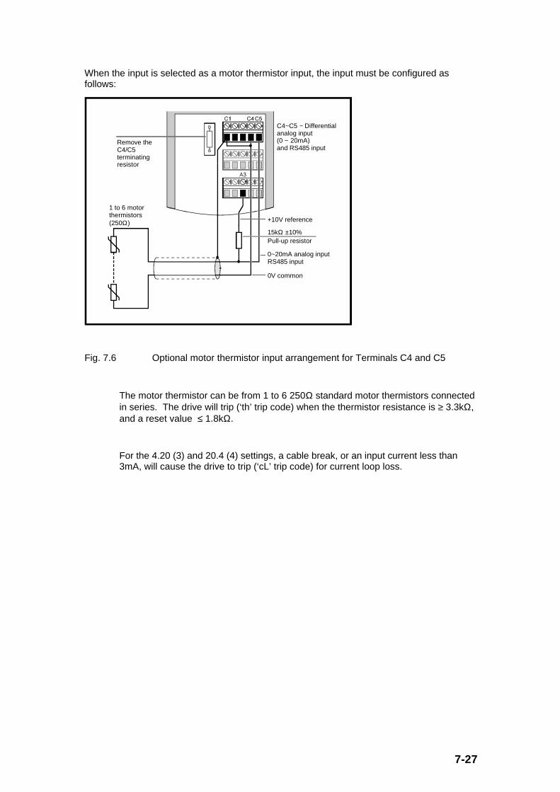
7-27
When the input is selected as a motor thermistor input, the input must be configured asfollows:
15kΩ ±10%
+10V reference
0V common
0~20mA analog inputRS485 input
1 to 6 motor thermistors(250Ω)
Remove the C4/C5 terminating resistor
Pull-up resistor
C4~C5 − Differential analog input (0 ~ 20mA) and RS485 input
Fig. 7.6 Optional motor thermistor input arrangement for Terminals C4 and C5
The motor thermistor can be from 1 to 6 250Ω standard motor thermistors connectedin series. The drive will trip (‘th’ trip code) when the thermistor resistance is ≥ 3.3kΩ,and a reset value ≤ 1.8kΩ.
For the 4.20 (3) and 20.4 (4) settings, a cable break, or an input current less than3mA, will cause the drive to trip (‘cL’ trip code) for current loop loss.
7-28
#0.26 Not programmed
#0.27
#0.28
#0.29
#0.30
Parameter type: C
Defined via: #b.16 (for #0.26)
#b.17 (for #0.27)
#b.18 (for #0.28)
#b.19 (for #0.29)
#b.20 (for #0.30)
#0.31 Reserved for other drive parameters
#0.32
#0.33
#0.34
#0.35
#0.36
Parameter type: F

7-29
#0.37 Serial interface address
Parameter type: RW, U, P, F
Corresponds with: #b.23
Adjustment range: 0.0 to 9.9
Units: [group.unit]
Default value: 1.1
Related parameters: #0.25, #b.26
If parameter #0.25 is set to ANS (0) (default) the serial interface is active.Parameter #0.37 defines the serial address of the drive. The address has thefollowing format: [drive group. drive unit]. There are 9 addressable groups for eachof 9 possible drive units. If address [0.0] is used, all drives are addressedsimultaneously. If [x.0] is used, where x is any number from 1 to 9, all drives ingroup x are addressed.
Note that for this drive, the only baud rate available is 4800.
#0.38 Initial parameter displayed selector
Parameter type: RW, U, F
Corresponds with: #b.22
Adjustment range: 0 to 50 (i.e. #0.00 to #0.50)
Units: (#0.) (Value is parameter number in Menu 0)
Default value: 10 (i.e. #0.10)
Related parameters: -
This parameter defines the parameter in Menu 0 which is selected when power isfirst applied to the drive (i.e. #0.10 is the default parameter displayed after ‘MODE’
is pressed following power up).
7-30
#0.39 Reserved for other drive parameters
#0.40
Parameter type: F
#0.41 PWM switching frequency
Parameter type: RW, U, T, P, F
Corresponds with: #5.18
Adjustment range: 3 (0), 6 (1), 9 (2), or 12 (3)
Units: kHz
Default value: 3 (0)
Related parameters: #0.01, #0.02
This parameter sets the PWM switching frequency of the Dinverter.
#0.41 Setting
(Display)
Setting via
Serial
comms
Description
3 0 3kHz PWM switching frequency (actually 2.9kHz)
6 1 6kHz PWM switching frequency (actually 5.8kHz)
9 2 9kHz PWM switching frequency (actually 8.8kHz)
12 3 12kHz PWM switching frequency (actually 11.7kHz)
The output frequency of the drive ([#0.10]) is limited by the switching frequencyselected as follows:
Switchingfrequency
Maximum output frequency(Upper limit frequency - ULF)
3kHz 240Hz
6kHz 480Hz
9kHz 720Hz
12kHz 960Hz
The maximum output frequency for each switching frequency is known as the UpperLimit Frequency and is used as the maximum range of some parameters. It shouldbe noted that if a maximum speed limit (#0.01 or #0.02) is set to an upper limitfrequency, there will be no head room for the drive to increase frequency above thislevel to affect slip compensation. If slip compensation is required the user mustensure that a switching frequency is selected which allows the output frequency torise enough to allow the compensation.
7-31
#0.42 Motor - number of poles
Parameter type: RW, U, T, P, F
Corresponds with: #5.11
Adjustment range: 2P (0), 4P (1), 6P (2), or 8P (3)
Units: Number of poles
Default value: 4P (1)
Related parameters: #0.45
The number of poles should be entered, not the number of pole-pairs.
#0.42 Setting
(Display)
Setting via
Serial
comms
Description
2P 0 2 Motor poles
4P 1 4 Motor poles
6P 2 6 Motor poles
8P 3 8 Motor poles
It is essential that this parameter is set for the particular motor used for correctoperation of the drive and all related speed and slip parameters.
Example: An induction motor has a rated speed of 1,440rpm and a ratedfrequency of 50Hz. Therefore, the motor is 4-pole, and this parameter is set to 4P(or 1 using serial comms).
#0.43 Motor - rated power factor
Parameter type: RW, U, P, F
Corresponds with: #5.10
Adjustment range: 0.00 to 0.85 x (FLC)/[#0.46]
where: FLC = drive rated current [#b.32]
#0.46 is the Motor - rated current
with a maximum possible value of 1.00
Units: -
Default value: 0.85
Related parameters: #0.06, #0.46
7-32
The motor power factor (cos ϕ) is used in conjunction with parameter #0.46 (motorrated current) to calculate the rated active current (i.e. rated active current = [#0.46]x [#0.43]). The rated active current is used extensively to control the drive.
It is therefore essential that this parameter is set for the particular motor used forcorrect operation of the drive and all related current parameters.
#0.44 Motor - rated voltage
Parameter type: RW, U, F
Corresponds with: #5.09
Adjustment range: 0.0 to 100.0
Units: % (of input supply voltage)
Default value: 100.0
Related parameters: #0.07, #0.08, #0.09
The motor rated voltage for the winding connection must be entered into thisparameter according to the motor nameplate rated voltage
Example: Motor used : 50Hz, 230V in delta, 400V in star connection
Supply voltage available: 240VAC
Settings: The motor is operated in a delta connection where:
[#0.44] = (Motor voltage) x 100%/ (Supply voltage)
= 230 x 100%/240
= 96%
It is essential that this parameter is set for the particular motor used for correctoperation of the drive and other related voltage parameters, such as dynamic V/f,boost, etc.
#0.45 Motor - rated full load slip (rpm)
Parameter type: RW, U, F
Corresponds with: #5.08
Adjustment range: 0 to 250
Units: rpm
Default value: 0
Related parameters: #0.10, #0.42
7-33
Entry of the motor rated full load slip activates slip compensation. The default valueof 0 disables slip compensation.
By changing this parameter value, the motor can either be over or undercompensated for slip as necessary (i.e. the shaft speed can be made to increase ordecrease with mechanical load as necessary).
Slip compensation will not alter the frequency direction defined by the post-rampfrequency reference ([#0.12]).
The ‘best guess’ value to achieve good slip compensation (i.e. no shaft speedchange with load) is calculated as follows:
[#0.45] = [#0.47] x 120/[#0.42] - (Motor nameplate full load speed in rpm)
where: #0.42 is the Motor - number of poles (use values of 2, 4, 6 or 8)
#0.47 is the Motor - rated frequency
Example: For a 50Hz 4-pole machine rated at 1,450rpm
[#0.45] = 50 x 120 / 4 - 1450
= 50 rpm
#0.46 Motor - rated current
Parameter type: RW, U, F
Corresponds with: #5.07
Adjustment range: 0.0 to drive rated current (FLC)
Units: A
Default value: Drive rated current (FLC) where
FLC = 4.3A for DIN1220075A,
FLC = 3.0A for DIN1220055A,
FLC = 2.3A for DIN1220037A,
FLC = 1.5A for DIN1220025A,
Related parameters: #0.06, #0.07, #0.08, #0.09, #0.45, #4.15
The value set in #0.46 should be the motor rated current from the motor nameplate,taking into account the winding connection (i.e. star or delta).
7-34
This parameter value is used in the following parameter calculations:
Current limit, parameter #0.06
Motor thermal Ixt overload, parameter #4.15
Slip compensation, parameter #0.45
Dynamic V/f control, parameter #0.09
Auto boost, parameter #0.07
Therefore it is essential that this parameter is set for the particular motor used forcorrect operation of the drive.
#0.47 Motor - rated frequency
Parameter type: RW, U, F
Corresponds with: #5.06
Adjustment range: 0.0 to ULF, where:
ULF = 240Hz when #0.41 = 3 (kHz),
ULF = 480Hz when #0.41 = 6 (kHz),
ULF = 720Hz when #0.41 = 9 (kHz),
ULF = 960Hz when #0.41 = 12 (kHz)
Units: Hz
Default value: 50.0 (when #x.00 set to 533 followed by a ‘RESET’), or
60.0 (when #x.00 set to 544 followed by a ‘RESET’).
Related parameters: #0.44
The motor rated frequency, in conjunction with #0.44 (Motor rated voltage), is usedto define the voltage to frequency characteristic applied to the motor.
Therefore it is essential that this parameter is set for the particular motor used forcorrect operation of the drive.

7-35
#0.48 Reserved for other drive parameters
Parameter type: F
#0.49 Security status
Parameter type: RO, U, P, F
Corresponds with: -
Range: 0 to 111
Units: -
Default value: 1
Related parameters: #x.00, #b.30
After power is applied to the drive, only access to the parameters in Menu 0 isavailable. Access to the extended menus, after the supply is connected, is onlypossible after entering a standard access code value of 149 into parameter #x.00.
The user security code is in parameter #b.30 and can be changed from its defaultvalue of 149 according to the users requirements.
Parameter #0.49 consists of 3 digits (xyz where x, y, z = 0, 1 or blank) andrepresents the security status:
x (or hundreds digit) y (or tens digit) z (or units digit)
0 or blank = no user-defined security codeentered into #b.30
1 = user defined securitycode set in #b.30
0 or blank = read/writeaccess to all menus or nouser-defined securityentered
1 = user-defined securityactive, no write access toany menus
0 = access to all menus (allmenus open) (i.e.[#x.00] set to149)
1 = [#x.00] not set to 149, noaccess to extended menus

7-36
The resulting value of #0.49 provides the following keypad access capability:
Value of #0.49 Access provided:
100 or 0 View and modify Menus 0 to E parameters
101 or 1 View and modify Menu 0 parameters only
110 only View Menus 0 to E parameters only
111 only View Menu 0 parameters only
#0.50 Software version
Parameter type: RO, U, P, F
Corresponds with: #b.29
Range: 1.00 to 9.99
Units: -
Default value: 1.03
Related parameters: -
This parameter displays the version of the installed software. For the default valuegiven above, the software version is V1.03.xx where xx is any number from 00 to 99and only corresponds to software ‘bug’ fixes which do not affect the drivespecification or this manual. Whereas the next version of software released V1.04.xxwill have specification changes that will affect the operation of the drive and this UserGuide.
__________
8-1
8.0 Commissioning - Getting Started
8.1 Warnings
Safety of application:
Careful consideration must be given to safety aspects of the system in which the drive isincorporated.
The drive is a complex system containing many electronic components and software.Control Techniques has made every effort to minimise the failure rate and to eliminateprogramming errors. However in common with all such drives the integrity of the unit is nothigh enough to carry out safety-related functions without independent high-integrityprotection.
In any application where a drive malfunction could lead to damage or loss or injury, a riskanalysis must be carried out, and where necessary further measures taken to reduce the risk.This would normally be some form of independent safety back-up system using simpleelectro-mechanical components.
Some common examples of functions which might be safety-related are:
− Stop/start, and emergency stop
− Auto-start
− Forward/reverse
− Maximum speed
However there may be others, depending on the exact application. These will be revealed bythe risk assessment.
Warning
Some of the parameters have a profound effect on drive operation. They must not be alteredwithout careful consideration to the impact on the controlled plant, and measures must betaken to prevent unwanted changes through error or tampering.

8-2
Motor Speed/Safety
Standard squirrel-cage AC induction motors are designed as single speed motors. If it isintended to use the capability of the drive to run the motor at speeds above its designedmaximum, it is strongly recommended that the motor manufacturer is consulted first. Theprincipal risks due to overspeeding are the destruction of the rotor by centrifugal force, or ofthe bearings by vibration and overheat.
Do not rely on the maximum speed setting parameter of the drive for overspeed protection.If the possibility of overspeeding is a serious problem, other means of protection must beprovided.
Low speed operation may result in overheating of the motor because the effectiveness of theinternal cooling fan reduces with shaft speed. Motors should be equipped with thermistorprotection, and if full benefit of the use at low speeds is to be gained it may be necessary toarrange additional forced cooling for the motor.
The drive contains capacitors which remain charged to a potentially hazardous voltage afterthe supply is removed. A period of at least 8 minutes must be allowed betweendisconnecting the supply and gaining access to the connections of the drive.
The drive is capable of causing damage to machinery if incorrectly adjusted. Take carewhen making any adjustments. Ensure that the motor shaft is not exposed. Ensure thatthe motor is mounted in accordance with the manufacturers recommendations. Ensure thatall personnel in the area are aware and warned that adjustments are to be made to the drive.Never work on a variable speed drive alone. Always have a fellow worker near to you toassist in the case of an emergency. Any adjustments to the drive that are performed shouldbe recorded.
8.2 Initial Electrical and Mechanical Set-Up

8-3
Prior to powering the drive up for the first time, ensure that Sections 4 & 5 of this manualhave been studied and the necessary recommended actions have been taken. For initialoperation and set-up of the drive, it is assumed that the connections are as shown in Fig 8.1.
0V common
RS485 input
Run forward
Run reverse
Drive enable
External trip
Analog speed reference
Status relay contacts (250VAC, 2A N/O) (optional connection)
Optional braking resistor ≥100Ω
Optional RFI filter
AC supplyFuses and isolator
Analog frequency output signal
Digital inputs
C4/C5 terminating resistor (100Ω) across C4~C5 (0 ~ 20mA) RS485 inputs
Brake
0V common
+10V, 5mA maximum
0V common
Gland X: 3 x 2.5mm (14AWG)
Gland Y: 6 x 1.0mm (18AWG)
Gland Z: 10 x 0.5mm (20AWG)
2
2
2
Optional
Fig. 8.1 Electrical connections for initial set-up and operation
In particular:
• Check that the wiring is correct,• Check that the motor installation is correct and safe,• Check that the motor shaft is not exposed,• Check that the signal connections B2, and B3 are not connected to 0V Common (i.e. the
switches/contacts are open), and B4 and B5 are connected to 0V Common (i.e. theswitches/contacts are closed). This ensures that the motor will not turn when AC power isapplied to the drive.
• Check that the Set Speed Potentiometer (connected to A1, A2, and A3) is set to minimum(wiper is effectively connected to 0V Common wiper).
Before switching on the power to the drive, it is important to understand the drive operatingcontrols and their operation. If in doubt, DO NOT ADJUST this drive. Damage may occur,or lives may be put at risk. Please read the following Sections carefully.

8-4
8.3 Configuring Drive for Connected Motor(s)
1) With the drive wired up as described in Section 8.2 above, apply power to the input of thedrive.
- drive should power up with ‘rdy’ on the display.
2) If the drive is already in the default set-up (with all parameters set to the default state)bypass this step, otherwise set defaults as follows:
(Note that the following example sets 50Hz defaults. If 60Hz defaults arerequired set Parameter 0 (i.e. #0.00) to a value of 544 not 533.)
- Select Parameter 0 (i.e. #0.00)
( Press ‘MODE’ followed by pressing ‘DOWN’ repeatedly to movefrom #0.10 to #0.00)
- Enter a value of 533 (for 60Hz motors set a value of 544)
( Press ‘MODE’ followed by pressing and holding ‘UP’ until a value of533 is displayed.)
Or:
(Press ‘MODE’ followed by ‘left’ (‘DOWN’ and ‘MODE’ simultaneously), then ‘left’ again, until ‘_ 0’ is displayed.
Press ‘UP’ repeatedly until ‘500’ is displayed.
Press ‘right’ (‘MODE’ and ‘UP’ simultaneously), when ‘500’ isdisplayed.
Press ‘UP’ repeatedly until ‘530’ is displayed.
Press ‘right’ (‘MODE’ and ‘UP’ simultaneously), when ‘530’ isdisplayed
Press ‘UP’ repeatedly until ‘533’ is displayed.)
- Press ‘STOP/RESET’ to reset the drive and enter default values.
- Store the default parameters for later use
(Set Parameter #0.00 to 900 (as already explained above for setting [#0.00]= 533).
Press ‘STOP/RESET’ to reset the drive and store default values.)
- Default values will always be used from now on whenever the drive is first poweredup, unless other parameters are changed and saved.

8-5
3) Enter the motor data into parameters #0.42 to #0.47 according to the nameplatedetails and supply connections.
#0.42 - Enter the number of motor poles (if different to default valueof “4P”.)
#0.43 - Enter motor power factor if different to default value.
#0.44 - Enter motor rated voltage if different to default value of100% of supply voltage.
#0.45 - Enter motor full load slip in rpm if slip compensation required(otherwise leave at 0 default value).
#0.46 - Enter motor full load current if different from (but must beless than) drive full load current rating.
#0.47 - Enter motor rated frequency if different from default value of50.0 or 60.0Hz depending on the value set in Parameter 0 for enteringdefaults.
Care must be taken that #0.44 and #0.47 are set correctly according to the motor ratedvoltage, Υ or ∆ connections used, motor rated frequency and drive supply voltage.
For example, if: motor rated voltage = 415V in Υ
motor rated frequency = 50Hz
drive supply voltage = 240VAC
motor full load current = 2.5A
Connect motor in ∆ for suitable operation.
Set: #0.44 = (415V/√3/240V) x 100%
= 100%
#0.46 = 2.5A x √3
= 4.3A
#0.47 = 50Hz x 100%/[#0.44]
= 50Hz
If motor could not be connected in ∆, only Υ:
Set: #0.44 = (415V/240VAC) x 100%
= (173%) (but can only set to 100% maximum)
= 100%
#0.46 = 2.5A
#0.47 = 50Hz x 100%/[#0.44 i.e. 173%]
= 29Hz
(As a result of the settings, the drive can only provide full load torque up to29Hz.)

8-6
8.4 Operating Drive Using Control Terminal Inputs
1. Select the required PWM switching frequency via #0.41, for suitable motornoise (although the default value of 3kHz (i.e. [#0.41] = 3 (kHz)) should be adequate andminimises drive power stage losses).
2. Leave acceleration and deceleration rates at their default values for the timebeing.
3. Disconnect the motor mechanical load if possible, as the motor direction maybe incorrect.
4. Set the desired minimum and maximum frequencies (#0.01 and #0.02).
5. Set the frequency demand to its minimum values by ensuring the potentiometerconnected at A2 is set at the 0V Common position.
6. Set the drive to run forward (close terminal B2):
- Drive runs to minimum frequency.
- Increase potentiometer setting until the motor turns slowly.
- Check the motor direction. If wrong change the direction by terminalcontrol (i.e. open terminal B2 and close terminal B3). (If this isnot desirable, power off the drive and then when safe exchangetwo motor phase connections from the drive)
Note: The Dinverter A currently operates the motor in the reverse directionto that if the a normal 3-phase AC supply is directly connected to the motor. Pleasecheck the motor rotation with the drive motor combination before progressing.
7. Run slowly through the frequency range. Slowly increase the potentiometersetting to the maximum value and observe the motor.
8. Stop the motor by opening B2 or B3 connection.
9. Power off the drive and reconnect the motor to its load.
10. With the frequency demand set to minimum again, set the drive to run. If thedrive does not start at the required speed increase the boost voltage (#0.08) until itdoes. If this does not give suitable starting performance set #0.08 to 0.0% and set#0.07 to 0 (fixed boost). Increase #0.08 until suitable low speed running is achieved.

8-7
11. Save the parameters before proceeding further.
12. Set up the acceleration rate using #0.03. Set the potentiometer to the maximumsetting when the drive is in a stop condition, and then start the motor by closing B2 orB3. If an ‘OI’ overcurrent trip occurs, the acceleration torque required is too high.This can be changed by extending the acceleration rate (i.e. increasing #0.03), or,especially for drives with large connected motor inertia, by adjusting the I (integral )term of the current control loop via #4.14 (generally increase the value). Increasingthe integral gain may cause instability. If this occurs, increase the proportional gainto re-stabilise the control.
It is useful to observe the motor frequency [#5.01] via an oscilloscope on terminal C2(default settings). If this gives no indication as to why the ramp cannot bemaintained, observe the motor percentage load [#4.20] using terminal C2 by setting[#7.19] to 4.20. Check whether the current limit [#0.06] is being reached and adjust ifpossible.
13. Set up the deceleration rate.
According to the application, #0.16 should be set to the required stop mode.Parameter #0.16 defines the action taken by the drive when a stop command isgiven (or removal of the run signal in default conditions).
Selection of type of
deceleration ramp:
The setting of parameter #0.15 (deceleration mode selector) definesthe deceleration characteristic.
If a braking resistor is used, the parameter should always be on ‘FSt’.If no braking resistor is used, it is recommended to set the parameterto ‘Std’ (controlled deceleration ramp with ramp hold).
The less critical mode is ‘Std’, in that if the braking torque is too high,the deceleration ramp will be temporarily held when the DC link hasrisen to a level where the brake transistor is turned on. Thedeceleration ramp is resumed when the DC link voltage has droppedto a lower threshold when the brake is turned off. The motor willdecelerate towards zero speed in a staircase fashion. Furtherparameter settings are not necessary. Note that in this mode theexternal braking resistor has less effect, since the deceleration rampis held whenever the brake turns on.

8-8
Set up of deceleration
rate:
Set the deceleration rate to the required value (#0.04).
(Note that the value for the deceleration rate relates to a ramp timefrom 100Hz to 0Hz.)
Run the drive at maximum speed. Now set the speed demand tozero or apply a stop signal (with #0.16 set to ‘rP’ or ‘rP.I’). The drivewill now decelerate according to the set deceleration rate. If theconverter trips (e.g. ‘OI’ or ‘OU’) the braking torque is too high.Increasing the deceleration rate will help. If a deceleration ramptime is required by the application which causes tripping, a brakingresistor must be installed and the parameter #0.15 needs to be set to‘FSt’.
15. The basic commissioning is now concluded.
8.5 Operating the Drive Using the Keypad
Note that this section assumes all parameters are at the default values.
1. Select the required PWM switching frequency via #0.41, for suitable motornoise although the default value of 3kHz (i.e. [#0.41] = 3 (kHz)) should be adequate andminimises drive power stage losses.
2. Leave acceleration and deceleration rates at their default values for the timebeing.
3. Disconnect the motor mechanical load if possible, as the motor direction maybe incorrect.
4. Set the desired minimum and maximum frequencies (#0.01 and #0.02).
5. Set #0.05 (the frequency reference selector) to 4 to select the keypad
reference for frequency/’speed’ control, and . enabling the ‘RUN’ , ‘STOP’ and
‘FWD/REV’ keys on the keypad. (Restore the display to the default parameter of #0.10to observe the frequency adjustment.)
6. Press ‘RUN’ to start the drive.
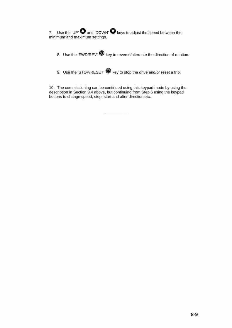
8-9
7. Use the ‘UP’ and ‘DOWN’ keys to adjust the speed between theminimum and maximum settings.
8. Use the ‘FWD/REV’ key to reverse/alternate the direction of rotation.
9. Use the ‘STOP/RESET’ key to stop the drive and/or reset a trip.
10. The commissioning can be continued using this keypad mode by using thedescription in Section 8.4 above, but continuing from Step 6 using the keypadbuttons to change speed, stop, start and alter direction etc.
__________

8-10

9-1
9.0 Extended Menus (1 through to 9, A, b, c, E) Parameter Descriptions
9.1 General
All parameters are grouped into 14 menus. Each of the extended menus 1 through to Egroup together common parameter types. As listed in Section 6.4.4, the extended menus orparameter groups are as follows:
(Please note that Menu 0 is detailed in Section 7.0 and is not included in this Section, andsimilarly Parameter 0 is defined in Sections 6.4.3 and 7.4.)
Menu Description
1 Frequency reference selection, limits and filters
- All frequency reference sources are selected via this menu, together withfrequency maximums and minimums, as well as skip frequencies.
2 Ramps
- Forward and reverse, as well as various accel/decel ramps can beindependently selected as required.
3 Frequency/speed sensing thresholds
- Two speed/frequency thresholds are adjustable in this menu.
4 Current control
- Drive current/torque control and limits as well as protection modes areavailable in this menu.
5 Machine control
- Motor settings are input to configure the drive correctly.
6 Drive sequencer and run-time clock
- Stopping and starting modes are selected in this menu together with a clockfor recording running time.
7 Analogue inputs and outputs
- Set-up of the analogue inputs/outputs is provided here, including where theinput is destined to go for internal operation and where the output sources itslevel from.
8 Digital inputs and outputs
- Set-up of the digital inputs/outputs including destinations (for inputs) andsignal sources (for outputs).
9 Programmable logic and motorised potentiometer
- An independent logic function where 2 digital inputs are combined to give adigital output, as well as a motorised potentiometer function.

9-2
A Status logic and diagnostics
- All relevant internal status bits are grouped here, together with the last 10trips information, and auto-reset control.
b Miscellaneous and Menu 0 parameter selectors
- Miscellaneous functions include serial communications set-up and usersecurity, as well as drive rating information.
c Programmable threshold
- An independent threshold can be programmed as required (i.e. analoguesources to digital output).
d Not used - only Parameter 0, i.e. #d.00 is available
E PID controller
- An independent PID loop is available for any 2 analogue sources toproduce an analogue feedback output.
The parameter types used throughout the following menu descriptions are as follows:
RW Read/WriteRead/ write parameter. (Parameters that can be set (written) by theuser, as well as read.)
RO Read Only Read only parameter for displaying operating modes and parametervalues. (Parameters that can be read by the user but not set by thekeypad, although the drive software has read/write access tothem.)
Bit Bit Bit parameter, can exist in only 2 states, 0 or 1.
B Bipolar Bipolar parameter, can have positive or negative values.
U Unipolar Unipolar parameter, can have only positive values.
T Text Parameter has different options. Options are specified viatext (or character string).
R Reset Parameter needs a RESET signal to implement valuechanges.
S Saved Parameter is saved automatically by mains switch off.
P Protected Parameter cannot be selected via programmable inputs andfunctions.

9-3
In the logic block diagrams for all the menus the following source/destination symbols havethese meanings:
(diamond) - Read only (RO)
(rectangle/square) - Read/write (R/W)
5.26 - Parameter #5.26
The following sections give a block diagram of each menu together with a summary of theparameters in that menu. At the end of this parameter summary, a complete description isgiven for each parameter.
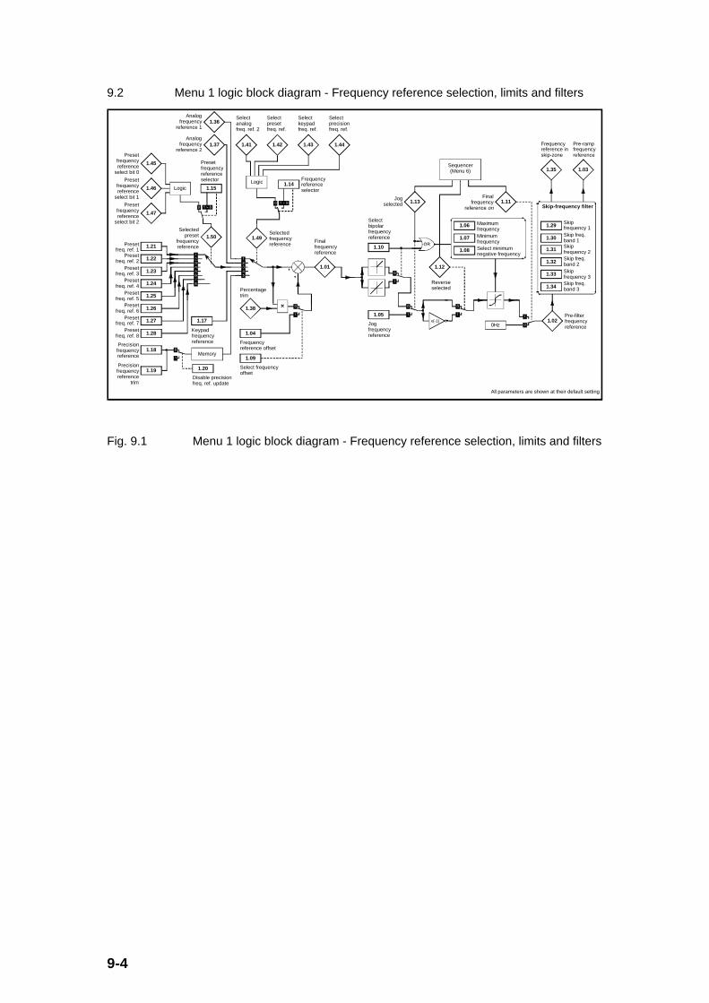
9-4
9.2 Menu 1 logic block diagram - Frequency reference selection, limits and filters
1.21Preset freq. ref. 1
1.22Preset
freq. ref. 2
1.23Preset
freq. ref. 3
1.24Preset
freq. ref. 4
1.25Preset freq. ref. 5
1.26Preset
freq. ref. 6
1.27Preset freq. ref. 7
1.28Preset
freq. ref. 8
1.15
Preset frequency reference selector
1.50Selected
preset frequency reference
1.17
Keypad frequency reference
1.18Precision
frequency reference
1.19Precision
frequency reference
trim
1.20
Disable precision freq. ref. update
Memory1.09
Select frequency offset
1.04
Frequency reference offset
1.49Selected frequency reference
1.05
Jog frequency reference
x(-1)
1.12
Reverse selected
1.11Final
frequency reference on
1.06 Maximum frequency
1.07 Minimum frequency
1.08 Select minimum negative frequency
Sequencer(Menu 6)
1.02Pre-filter frequency reference
1.35
Frequency reference in skip-zone
1.03
Pre-ramp frequency reference
1.29 Skip frequency 1
1.30Skip freq. band 1
1.31Skip frequency 2
1.32Skip freq. band 2
1.33 Skip frequency 3
1.34Skip freq. band 3
Skip-frequency filter
1.10
Select bipolar frequency reference
1.13Jog
selected
1.01
Final frequency reference
All parameters are shown at their default setting
1.36Analog
frequency reference 1
1.37Analog
frequency reference 2
1.45
Preset frequency reference
select bit 0
1.46
Preset frequency reference
select bit 1
1.47
Preset frequency reference
select bit 2
Logic
1.38
Percentage trim
Logic 1.14Frequency reference selector
1.41
Select analog freq. ref. 2
1.42
Select preset freq. ref.
1.43
Select keypad freq. ref.
1.44
Select precision freq. ref.
0Hz
Fig. 9.1 Menu 1 logic block diagram - Frequency reference selection, limits and filters

9-5
9.2.1 Menu 1 Parameter List
Parameter Description Type Range Default Units
#1.01 Selected final frequency reference RO, B, P 0.0 to ±ULF - Hz
#1.02 Pre-skip frequency reference RO, B, P 0.0 to ≈ ±[#1.06] - Hz
#1.03 Pre-ramp frequency reference RO, B, P 0.0 to ≈ ±[#1.06] - Hz
#1.04 Frequency reference offset RW, B 0.0 to ±ULF 0.0 Hz
#1.05 Jog frequency reference RW, U 0.0 to 400.0 1.5 Hz
#1.06 Maximum frequency RW, U 0.0 to ULF 50.0 or 60.0 Hz
#1.07 Minimum frequency RW, B 0.0 to ±ULF 0.0 Hz
#1.08 Select negative minimumfrequency
RW, Bit 0/1 0 -
#1.09 Select frequency offset RW, Bit 0/1 0 -
#1.10 Select bipolar frequency reference RW, Bit 0/1 0 -
#1.11 Final frequency reference ‘on’ RO, Bit, P 0/1 - -
#1.12 Reverse selected RO, Bit, P 0/1 - -
#1.13 Jog selected RO, Bit, P 0/1 - -
#1.14 Frequency reference selector RW, U, P 0 to 5 0 -
#1.15 Preset frequency referenceselector
RW, U, P 0 to 8 0 -
#1.16 Unused parameter - - - -
#1.17 Keypad frequency reference RO, B, S, P 0.0 to ±[#1.06] 0.0 Hz
#1.18 Precision frequency reference RW, B 0.0 to ±ULF 0.0 Hz
#1.19 Precision frequency reference trim RW, U 0 to 99 0 mHz
#1.20 Disable precision reference update RW, Bit 0/1 0 -
#1.21 Preset frequency reference 1 RW, B 0.0 to ±ULF 0.0 Hz
#1.22 Preset frequency reference 2 RW, B 0.0 to ±ULF 0.0 Hz
#1.23 Preset frequency reference 3 RW, B 0.0 to ±ULF 0.0 Hz
#1.24 Preset frequency reference 4 RW, B 0.0 to ±ULF 0.0 Hz
#1.25 Preset frequency reference 5 RW, B 0.0 to ±ULF 0.0 Hz
#1.26 Preset frequency reference 6 RW, B 0.0 to ±ULF 0.0 Hz
#1.27 Preset frequency reference 7 RW, B 0.0 to ±ULF 0.0 Hz
#1.28 Preset frequency reference 8 RW, B 0.0 to ±ULF 0.0 Hz
#1.29 Skip frequency 1 RW, U 0.0 to ULF 0.0 Hz

9-6
#1.30 Skip frequency band 1 RW, U 0.0 to 5.0 0.5 Hz
#1.31 Skip frequency 2 RW, U 0.0 to ULF 0.0 Hz
#1.32 Skip frequency band 2 RW, U 0.0 to 5.0 0.5 Hz
#1.33 Skip frequency 3 RW, U 0.0 to ULF 0.0 Hz
#1.34 Skip frequency band 3 RW, U 0.0 to 5.0 0.5 Hz
#1.35 Frequency reference in skip zone RO, Bit, P 0/1 - -
#1.36 Analogue frequency reference 1 RO, B 0.0 to ±[#1.06] - Hz
#1.37 Analogue frequency reference 2 RO, B 0.0 to ±[#1.06] - Hz
#1.38 Percentage trim RO, B 0.0 to ±100.0 - %
#1.39 Unused parameter - - - -
#1.40 Unused parameter - - - -
#1.41 Select analogue frequencyreference 2
RO, Bit 0/1 - -
#1.42 Select preset frequency reference RO, Bit 0/1 - -
#1.43 Select keypad frequency reference RO, Bit 0/1 - -
#1.44 Select precision frequencyreference
RO, Bit 0/1 - -
#1.45 Preset frequency reference selectbit 0
RO, Bit 0/1 - -
#1.46 Preset frequency reference selectbit 1
RO, Bit 0/1 - -
#1.47 Preset frequency reference selectbit 2
RO, Bit 0/1 - -
#1.48 Unused parameter - - - -
#1.49 Selected frequency reference RO, U, P 1 to 5 - -
#1.50 Selected preset frequencyreference
RO, U, P 1 to 8 - -

9-7
9.2.2 Menu 1 Parameter Descriptions
#1.01 Selected final frequency reference
Parameter type: RO, B, P
Range: 0.0 to ±ULF where: (ULF is the Upper Limit Frequency),
ULF = 240Hz when [#5.18] (or [#0.41]) = 3 (kHz),
ULF = 480Hz when [#5.18] (or [#0.41]) = 6 (kHz),
ULF = 720Hz when [#5.18] (or [#0.41]) = 9 (kHz),
ULF = 960Hz when [#5.18] (or [#0.41]) = 12 (kHz)
Units: Hz
Default value: -
The selected final frequency reference is useful for drive set-up and fault finding.This reference is the final reference selected from all of the possible references suchas analogue references, preset references, and keypad/precision references.
#1.02 Pre-skip frequency reference
#1.03 Pre-ramp frequency reference
Parameter type: RO, B, P
Range: [#1.07] to [#1.06], or, -[#1.07] to -[#1.06],
if [#1.08] = 0 ([#1.07] ≥ 0) , or
[#1.07] to [#1.06], if [#1.08] = 1 ([#1.07] ≤ 0)
Units: Hz
Default value: -
Both the pre-ramp and pre-skip frequency references are useful for drive set-up andfault finding.
The pre-skip frequency reference is the reference following inclusion of theforward/reverse demand and minimum/maximum limits on the selected finalfrequency reference (#1.01).
The pre-ramp frequency reference is the outcome of the skip frequencies on the pre-skip reference.

9-8
#1.04 Frequency reference offset
Parameter type: RW, B
Adjustment range: 0.0 to ±ULF where:
ULF = 240Hz when [#5.18] (or [#0.41]) = 3 (kHz),
ULF = 480Hz when [#5.18] (or [#0.41]) = 6 (kHz),
ULF = 720Hz when [#5.18] (or [#0.41]) = 9 (kHz),
ULF = 960Hz when [#5.18] (or [#0.41]) = 12 (kHz)
Units: Hz
Default value: 0.0
This frequency reference is added to the selected reference if the select frequencyoffset parameter (#1.09) is set to 1. It can be used as a trim to adjust the mainreference being selected.
#1.05 Jog frequency reference
Parameter type: RW, U
Adjustment range: 0.0 to 400.0, (limited to 240.0 by #1.06 when [#5.18] = 3(kHz))
Units: Hz
Default value: 1.5
This parameter is the frequency reference used for jogging.
If a value is set which is higher than the ULF (upper limit frequency) then the actualjog reference will be limited to the ULF value. Similarly the jog reference will belimited to the maximum frequency (i.e.[#1.06]) even though the set value could behigher than this.

9-9
#1.06 Maximum frequency
Parameter type: RW, U
Adjustment range: 0.0 to ULF, where:
ULF = 240Hz when [#5.18] (or [#0.41]) = 3 (kHz),
ULF = 480Hz when [#5.18] (or [#0.41]) = 6 (kHz),
ULF = 720Hz when [#5.18] (or [#0.41]) = 9 (kHz),
ULF = 960Hz when [#5.18] (or [#0.41]) = 12 (kHz)
Units: Hz
Default value: 50.0 (when #x.00 set to 533 followed by a ‘RESET’), or
60.0 (when #x.00 set to 544 followed by a ‘RESET’).
The maximum frequency parameter defines the absolute maximum frequencyreference. However, slip compensation and current/torque limits can increase theapplied motor frequency above this value.
If the select negative minimum frequency parameter (#1.08) is 0, #1.06 is asymmetrical limit in both directions of rotation. When [#1.08] is 1, this parameter is alimit in the forward direction only.
Parameter #1.06 is used as the maximum value of the analogue frequency reference1 and 2 parameters (#1.36 and #1.37 respectively) for correct scaling of analogueinputs provided the select negative minimum frequency parameter (#1.08) is 0. If[#1.08] is 1, then the scaling for #1.36 and #1.37 is based on the largest magnitudesof either [#1.06] or [#1.07].
Note that this parameter cannot be adjusted when the drive is enabled.
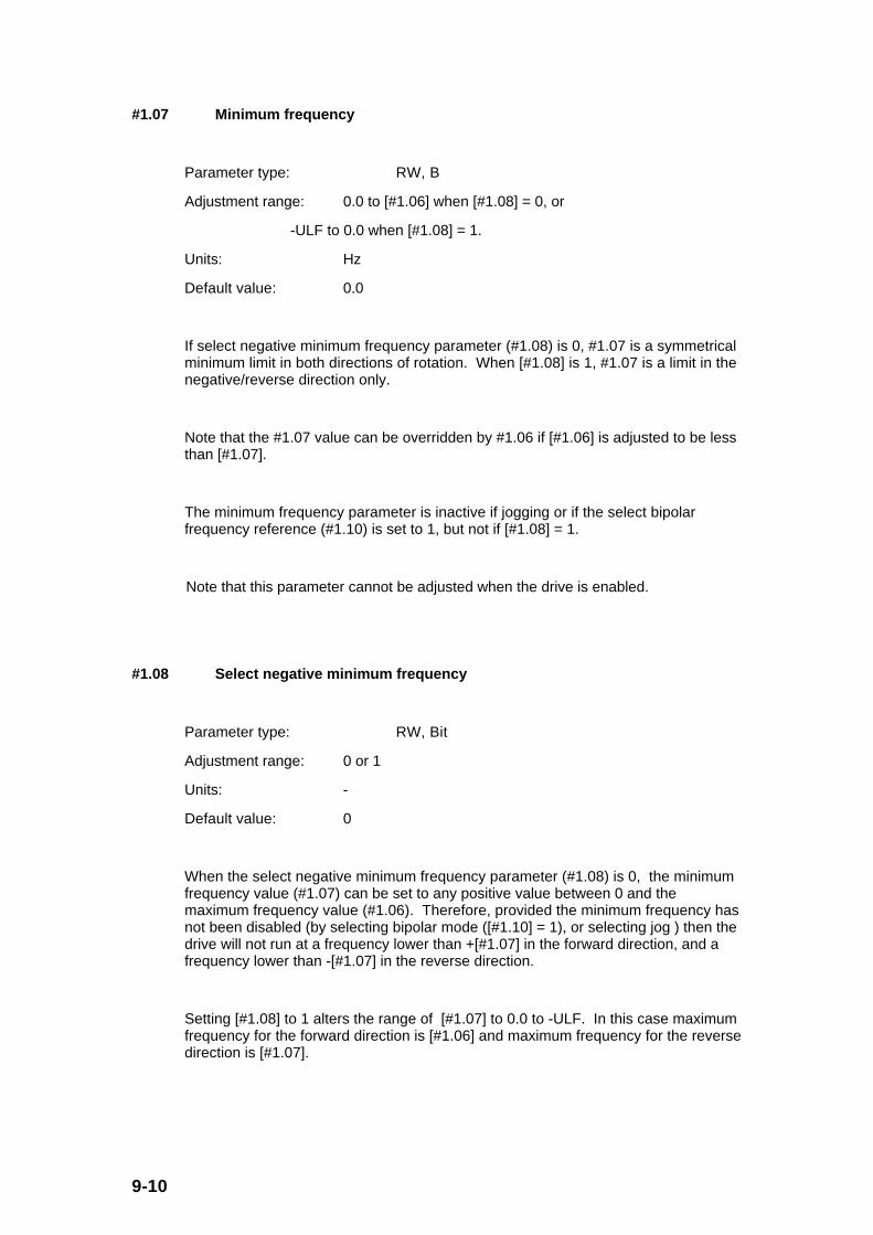
9-10
#1.07 Minimum frequency
Parameter type: RW, B
Adjustment range: 0.0 to [#1.06] when [#1.08] = 0, or
-ULF to 0.0 when [#1.08] = 1.
Units: Hz
Default value: 0.0
If select negative minimum frequency parameter (#1.08) is 0, #1.07 is a symmetricalminimum limit in both directions of rotation. When [#1.08] is 1, #1.07 is a limit in thenegative/reverse direction only.
Note that the #1.07 value can be overridden by #1.06 if [#1.06] is adjusted to be lessthan [#1.07].
The minimum frequency parameter is inactive if jogging or if the select bipolarfrequency reference (#1.10) is set to 1, but not if [#1.08] = 1.
Note that this parameter cannot be adjusted when the drive is enabled.
#1.08 Select negative minimum frequency
Parameter type: RW, Bit
Adjustment range: 0 or 1
Units: -
Default value: 0
When the select negative minimum frequency parameter (#1.08) is 0, the minimumfrequency value (#1.07) can be set to any positive value between 0 and themaximum frequency value (#1.06). Therefore, provided the minimum frequency hasnot been disabled (by selecting bipolar mode ([#1.10] = 1), or selecting jog ) then thedrive will not run at a frequency lower than +[#1.07] in the forward direction, and afrequency lower than -[#1.07] in the reverse direction.
Setting [#1.08] to 1 alters the range of [#1.07] to 0.0 to -ULF. In this case maximumfrequency for the forward direction is [#1.06] and maximum frequency for the reversedirection is [#1.07].
9-11
#1.09 Select frequency offset
Parameter type: RW, Bit
Adjustment range: 0 or 1
Units: -
Default value: 0
When the select frequency offset parameter is 0 the frequency offset added is apercentage trim derived from the selected frequency reference and the percentagetrim parameter (#1.38).
When [#1.09] is set to 1, the frequency offset added is the frequency reference offsetparameter (#1.04).
#1.10 Select bipolar frequency reference
Parameter type: RW, Bit
Adjustment range: 0 or 1
Units: -
Default value: 0
This parameter needs to be set to 1 if the user requires to change the direction ofrotation with a bipolar frequency reference. If #1.10 is not set, (i.e. [#1.10] = 0), allnegative frequency references are treated as zero.
#1.11 Final frequency reference ‘on’
#1.12 Reverse selected
#1.13 Jog selected
Parameter type: RO, Bit, P
Range: 0 or 1
Units: -
Default value: 0
These flags are controlled by the drive sequencer defined in Menu 6. The flagsselect the appropriate frequency reference as commanded by the drive sequencinglogic and illustrated in the block diagram above for Menu 1.

9-12
#1.14 Frequency reference selector
Parameter type: RW, U, P
Adjustment range: 0 to 5
Units: -
Default value: 0
This frequency reference selector parameter selects a frequency reference asfollows:
[#1.14] = 0 Reference selected by states of bit parameters #1.41 to#1.44
1 Analogue reference 1 selected ([#1.49] = 1)
2 Analogue reference 2 selected ([#1.49] = 2)
3 Preset reference selected ([#1.49] = 3)
4 Keypad reference selected ([#1.49] = 4)
5 Precision reference selected ([#1.49] = 5)
Where: #1.49 is the selected frequency reference.
When [#1.14] is set to 0 the reference selected depends on the state of bitparameters #1.41 to #1.44 as follows: (where x = 0 or 1)
[#1.41] -Select
analoguefrequency
reference 2
[#1.42] -Selectpreset
frequencyreference
[#1.43] -Selectkeypad
frequencyreference
[#1.44] -Select
precisionfrequencyreference
FrequencyReference Selected
SelectedFrequencyReferenceParameter([#1.49])
0 0 0 0 Analogue reference 1 1
1 0 0 0 Analogue reference 2 2
x 1 0 0 Preset reference 3
x x 1 0 Keypad reference 4
x x x 1 Precision reference 5
The bits #1.41 to #1.44 are provided to allow control by digital inputs such thatfrequency references can be selected by external control.

9-13
#1.15 Preset frequency reference selector
Parameter type: RW, U, P
Adjustment range: 0 to 8
Units: -
Default value: 0
This preset frequency reference selector parameter selects a preset frequencyreference as follows:
[#1.15] = 0 Preset reference selected by states of bit parameters #1.45to #1.47
1 Preset 1 selected ([#1.50] = 1)
2 Preset 2 selected ([#1.50] = 2)
3 Preset 3 selected ([#1.50] = 3)
4 Preset 4 selected ([#1.50] = 4)
5 Preset 5 selected ([#1.50] = 5)
6 Preset 6 selected ([#1.50] = 6)
7 Preset 7 selected ([#1.50] = 7)
8 Preset 8 selected ([#1.50] = 8)
Where: #1.50 is the selected preset frequency reference.
When [#1.15] is set to 0 the preset reference selected depends on the state of bitparameters #1.45 to #1.47 in a binary code as follows:
[#1.47] -Preset
frequencyreference
select bit 2
[#1.46] -Preset
frequencyreference
select bit 1
[#1.45] -Preset
frequencyreference
select bit 0
Selected presetfrequency reference
and Parameter[#1.50]
0 0 0 1
0 0 1 2
0 1 0 3
0 1 1 4
1 0 0 5
1 0 1 6
1 1 0 7
1 1 1 8
The bits #1.45 to #1.47 are provided to allow control by digital inputs such that presetreferences can be selected by external control.

9-14
#1.17 Keypad frequency reference
Parameter type: RO, B, S, P
Range: [#1.07] to [#1.06] (if [#1.08] = 0 and [#1.10] = 0), ([#1.07] is positive)
0.0 to ±[#1.06] (if [#1.08] = 0 and [#1.10] = 1),
0.0 to [#1.06] (if [#1.08] = 1 and [#1.10] = 0),
[#1.07] to [#1.06] (if [#1.08] = 1 and [#1.10] = 1), ([#1.07] is negative)
Units: Hz
Default value: 0.0
If this parameter is selected as the frequency reference (i.e. [#1.49] = 4), it is
adjusted by the ‘UP’ and ‘DOWN’ keys only when the display is in the StatusMode. When the drive is not enabled view the keypad reference by looking atparameter #1.17 to ensure the correct value is set before enabling the drive.
The value is saved on power down such that the keypad frequency reference doesnot have to be set up again on power up.
#1.18 Precision frequency reference
Parameter type: RW, B
Adjustment range: 0.0 to ±ULF
Units: Hz
Default value: 0.0
Setting this parameter in conjunction with the precision frequency reference trim(#1.19) allows a high resolution frequency control to be utilised. The high resolutioncapability is lost during acceleration/deceleration, current limit operation, and if slipcompensation is enabled (i.e. [#5.08] ≠ 0rpm).

9-15
#1.19 Precision frequency reference trim
Parameter type: RW, U
Adjustment range: 0 to 99
Units: mHz
Default value: 0
The precision frequency reference trim parameter in conjunction with the precisionfrequency reference (#1.18) allows a precision frequency reference to be set with aresolution of 0.001Hz or 1mHz.
Depending on the PWM switching frequency (#5.18) chosen, the drive has thefollowing available resolutions:
0.002Hz when [#5.18] (or [#0.41]) = 3 (kHz),
0.004Hz when [#5.18] (or [#0.41]) = 6 (kHz),
0.006Hz when [#5.18] (or [#0.41]) = 9 (kHz),
0.008Hz when [#5.18] (or [#0.41]) = 12 (kHz)
Where: #5.18 (or #0.41) is the PWM switching frequency..
#1.20 Disable precision reference update
Parameter type: RW, Bit
Adjustment range: 0 or 1
Units: -
Default value: 0
When this parameter is set to 0 the precision frequency reference parameters (#1.18and #1.19) are read and stored in internal memory. Because the precision referencehas to be set in two parameters, setting [#1.20] to 1 prevents the drive from readingparameters #1.18 and #1.19 while they are being updated. In this case (when [#1.20]= 1), the drive uses the previously stored values from memory for #1.18 and #1.19,thus preventing the possibility of data skew.

9-16
#1.21 Preset frequency reference 1
#1.22 Preset frequency reference 2
#1.23 Preset frequency reference 3
#1.24 Preset frequency reference 4
#1.25 Preset frequency reference 5
#1.26 Preset frequency reference 6
#1.27 Preset frequency reference 7
#1.28 Preset frequency reference 8
Parameter type: RW, B
Adjustment range: 0.0 to ±ULF
Units: Hz
Default value: 0.0
These parameters defines the 8 preset frequency references.
#1.29 Skip frequency 1
#1.31 Skip frequency 2
#1.33 Skip frequency 3
Parameter type: RW, U
Adjustment range: 0.0 to ULF
Units: Hz
Default value: 0.0
The 3 skip frequencies are available to prevent mechanical resonances in a system,by ensuring that certain frequencies can be avoided by always ramping throughthem.
When any skip frequency parameter is set to 0.0 (as default) the particular skipfrequency is disabled.
See the graph below illustrating the action of skip frequencies and associated skipfrequency bands.
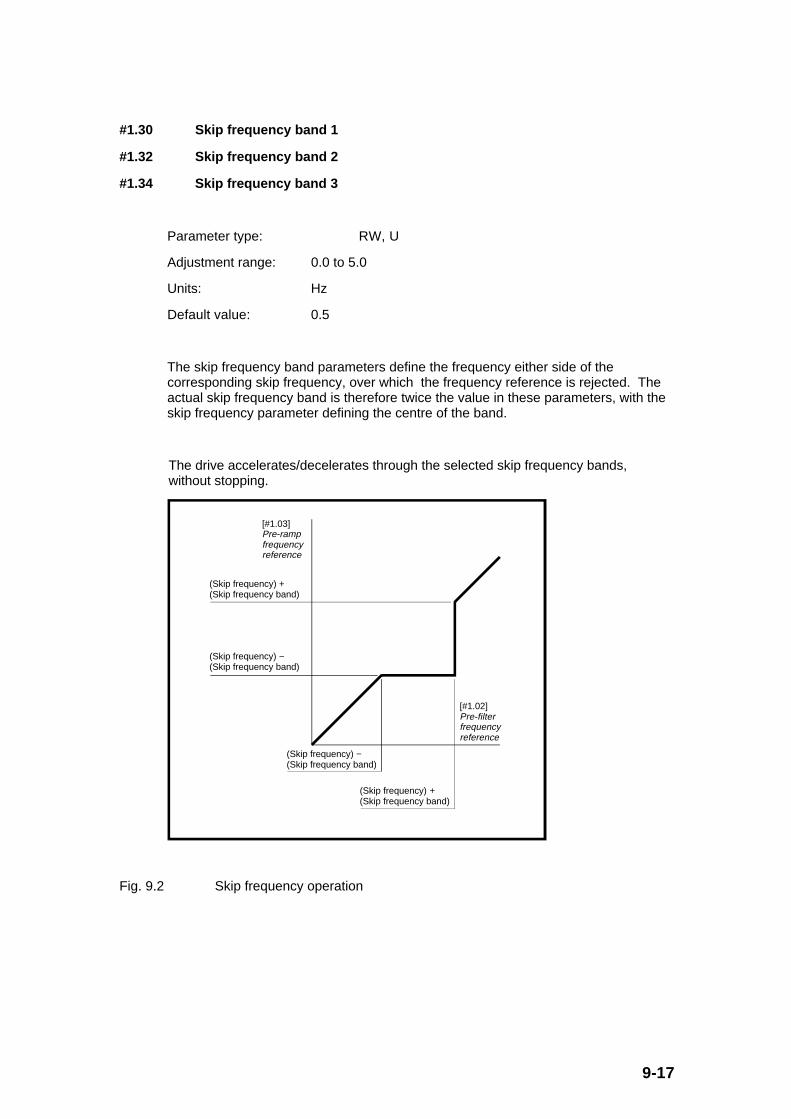
9-17
#1.30 Skip frequency band 1
#1.32 Skip frequency band 2
#1.34 Skip frequency band 3
Parameter type: RW, U
Adjustment range: 0.0 to 5.0
Units: Hz
Default value: 0.5
The skip frequency band parameters define the frequency either side of thecorresponding skip frequency, over which the frequency reference is rejected. Theactual skip frequency band is therefore twice the value in these parameters, with theskip frequency parameter defining the centre of the band.
The drive accelerates/decelerates through the selected skip frequency bands,without stopping.
[#1.03] Pre-ramp frequency reference
[#1.02] Pre-filter frequency reference
(Skip frequency) + (Skip frequency band)
(Skip frequency) − (Skip frequency band)
(Skip frequency) − (Skip frequency band)
(Skip frequency) + (Skip frequency band)
Fig. 9.2 Skip frequency operation
9-18
#1.35 Frequency reference in skip zone
Parameter type: RO, Bit, P
Range: 0 or 1
Units: -
Default value: -
The frequency reference in skip zone parameter indicates that the pre-skip frequencyreference is within one of the three skip frequency regions such that the motorfrequency is not as demanded, i.e. the pre-skip frequency reference (#1.02) isdifferent to the pre-ramp frequency reference (#1.03).
#1.36 Analogue frequency reference 1
#1.37 Analogue frequency reference 2
Parameter type: RO, B
Range: 0.0 to ±[#1.06] if [#1.08] = 0, or
0.0 to ±[maximum of |#1.06| and |#1.07|] if [#1.08] = 1
Units: Hz
Default value: -
These analogue frequency reference parameters are available for control byanalogue inputs which are required as frequency references. Parameters #7.10 and#7.14 are programmed with the destination parameters for the 2 analogue inputs.
The analogue frequency reference parameters are automatically scaled such that100.0% input corresponds to the set maximum frequency (#1.06 if [#1.08] = 0, or themaximum of #1.06 and #1.07 if [#1.08] = 1). Also the 0% input level corresponds tothe minimum frequency level (#1.07) if bipolar operation is not selected (i.e. [#1.10]= 0), and parameter #1.08 is set to 0. See the two figures below for further details.

9-19
[1.36] or [1.37] Analog frequency reference
Source of analog frequency reference
[#1.06]
[#1.07]
+100%0 (or <0%)
Fig. 9.3 Unipolar operation (i.e. [#1.10] = 0)
[#1.36] or [#1.37]Analog frequency reference
Source of analog frequency reference
+max_mag
−max_mag
100%
−100%
Fig. 9.4 Bipolar operation (i.e. [#1.10] = 1)
Where: (max_mag) = maximum frequency magnitude
= [#1.06] if [#1.08] = 0 or 1, but
= |[#1.07]| if [#1.08] = 1 and |[#1.07]| ≥ [#1.06]

9-20
#1.38 Percentage trim
Parameter type: RO, B
Range: 0.0 to ±100.0
Units: %
Default value: -
The percentage trim parameter (if selected, i.e. [#1.09] = 0) allows the selectedreference to be trimmed. As an example, if an analogue input is routed to thisparameter, the selected reference can be trimmed by the analogue input. Innumerical terms:
[#1.01] = (Selected Reference Value) x (1 + [#1.38]/100)
where: Selected Reference Value is defined by the Selected FrequencyReference (#1.49),
#1.01 is the selected final frequency reference
#1.39 Unused parameter
#1.40 Unused parameter
#1.41 Select analogue frequency reference 2
#1.42 Select preset frequency reference
#1.43 Select keypad frequency reference
#1.44 Select precision frequency reference
#1.45 Preset frequency reference select bit 0
#1.46 Preset frequency reference select bit 1
#1.47 Preset frequency reference select bit 2
Parameter type: RO, Bit
Range: 0 or 1
Units: -
Default value: -
These bits are provided for control by logic inputs (e.g. digital inputs) for externalreference selection (see parameters #1.14 and #1.15).
9-21
#1.48 Unused parameter
#1.49 Selected frequency reference
Parameter type: RO, U, P
Range: 1 to 5
Units: -
Default value: -
The selected frequency reference parameter indicates the frequency referencecurrently being selected. See the Frequency Reference Selector parameter (#1.14)description for further details.
#1.50 Selected preset frequency reference
Parameter type: RO, U, P
Range: 1 to 8
Units: -
Default value: -
The selected preset parameter indicates the preset frequency reference currentlybeing selected. See the Preset Frequency Reference Selector parameter (#1.15)description for further details.
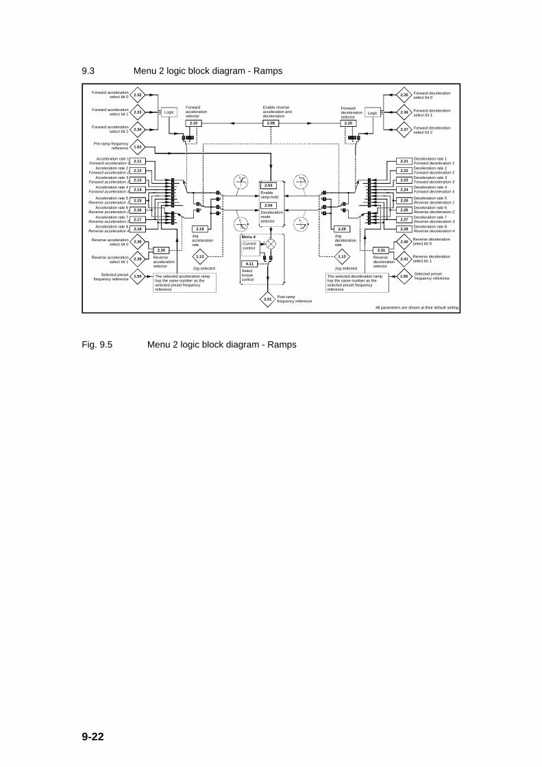
9-22
9.3 Menu 2 logic block diagram - Ramps
The selected acceleration ramp has the same number as the selected preset frequency reference
1.50Selected preset frequency reference
2.10
Forward acceleration selector
2.11Acceleration rate 1
Forward acceleration 1
2.12Acceleration rate 2
Forward acceleration 2
2.13Acceleration rate 3
Forward acceleration 3
2.14Acceleration rate 4
Forward acceleration 4
2.15Acceleration rate 5
Reverse acceleration 1
2.16Acceleration rate 6
Reverse acceleration 2
2.17Acceleration rate 7
Reverse acceleration 3
2.18Acceleration rate 8
Reverse acceleration 4
Logic
2.30
Reverse acceleration selector
2.09
Enable reverse acceleration and deceleration
2.19
Jog acceleration rate
1.03Pre-ramp frequency
reference
Menu 4
4.11
Select torque control
2.03
Enable ramp-hold
2.04
Deceleration mode selector
The selected deceleration ramp has the same number as the selected preset frequency reference
2.01Post-ramp frequency reference
2.20
Forward deceleration selector
2.21Deceleration rate 1 Forward deceleration 1
2.22Deceleration rate 2 Forward deceleration 2
2.23Deceleration rate 3 Forward deceleration 3
2.24Deceleration rate 4 Forward deceleration 4
2.25Deceleration rate 5 Reverse deceleration 1
2.26Deceleration rate 6 Reverse deceleration 2
2.27Deceleration rate 7 Reverse deceleration 3
2.28Deceleration rate 8 Reverse deceleration 4
2.31
Reverse deceleration selector
2.29
Jog deceleration rate
1.50Selected preset frequency reference
All parameters are shown at their default setting
2.32Forward acceleration
select bit 0
2.33Forward acceleration
select bit 1
2.34Forward acceleration
select bit 2
2.38Reverse acceleration select bit 0
2.39Reverse acceleration select bit 1
1.13
Jog selected
1.13
Jog selected
2.40Reverse deceleration select bit 0
2.41Reverse deceleration select bit 1
Current control
Logic
2.35 Forward deceleration select bit 0
2.36 Forward deceleration select bit 1
2.37 Forward deceleration select bit 2
Fig. 9.5 Menu 2 logic block diagram - Ramps

9-23
9.3.1 Menu 2 Parameter List
Parameter Description Type Range Default Units
#2.01 Post-ramp frequency reference RO, B, P 0 to ≈ ±[#1.06] - Hz
#2.02 Unused parameter - - - -
#2.03 Enable ramp hold RW, Bit 0/1 0 -
#2.04 Deceleration mode selector RW, U, T, P Std (0) or FSt (1) Std (0) -
#2.05 Unused parameter - - - -
#2.06 Unused parameter - - - -
#2.07 Unused parameter - - - -
#2.08 Unused parameter - - - -
#2.09 Enable reverse accel and decel RW, Bit 0/1 0 -
#2.10 Forward acceleration selector RW, U, P 0 to 9 0 -
#2.11 Accel 1/ forward accel 1 rate RW, U 0.0 to 999.0 5.0 s/100Hz
#2.12 Accel 2/ forward accel 2 rate RW, U 0.0 to 999.0 5.0 s/100Hz
#2.13 Accel 3/ forward accel 3 rate RW, U 0.0 to 999.0 5.0 s/100Hz
#2.14 Accel 4/ forward accel 4 rate RW, U 0.0 to 999.0 5.0 s/100Hz
#2.15 Accel 5/ reverse accel 1 rate RW, U 0.0 to 999.0 5.0 s/100Hz
#2.16 Accel 6/ reverse accel 2 rate RW, U 0.0 to 999.0 5.0 s/100Hz
#2.17 Accel 7/ reverse accel 3 rate RW, U 0.0 to 999.0 5.0 s/100Hz
#2.18 Accel 8/ reverse accel 4 rate RW, U 0.0 to 999.0 5.0 s/100Hz
#2.19 Jog acceleration rate RW, U 0.0 to 999.0 0.2 s/100Hz
#2.20 Forward deceleration selector RW, U, P 0 to 9 0 -
#2.21 Decel 1/ forward decel 1 rate RW, U 0.0 to 999.0 10.0 s/100Hz
#2.22 Decel 2/ forward decel 2 rate RW, U 0.0 to 999.0 10.0 s/100Hz
#2.23 Decel 3/ forward decel 3 rate RW, U 0.0 to 999.0 10.0 s/100Hz
#2.24 Decel 4/ forward decel 4 rate RW, U 0.0 to 999.0 10.0 s/100Hz
#2.25 Decel 5/ reverse decel 1 rate RW, U 0.0 to 999.0 10.0 s/100Hz
#2.26 Decel 6/ reverse decel 2 rate RW, U 0.0 to 999.0 10.0 s/100Hz
#2.27 Decel 7/ reverse decel 3 rate RW, U 0.0 to 999.0 10.0 s/100Hz
#2.28 Decel 8/ reverse decel 4 rate RW, U 0.0 to 999.0 10.0 s/100Hz
#2.29 Jog deceleration rate RW, U 0.0 to 999.0 0.2 s/100Hz
#2.30 Reverse acceleration selector RW, U, P 0 to 4 0 -

9-24
#2.31 Reverse deceleration selector RW, U, P 0 to 4 0 -
#2.32 Forward acceleration select bit 0 RO, Bit 0/1 - -
#2.33 Forward acceleration select bit 1 RO, Bit 0/1 - -
#2.34 Forward acceleration select bit 2 RO, Bit 0/1 - -
#2.35 Forward deceleration select bit 0 RO, Bit 0/1 - -
#2.36 Forward deceleration select bit 1 RO, Bit 0/1 - -
#2.37 Forward deceleration select bit 2 RO, Bit 0/1 - -
#2.38 Reverse acceleration select bit 0 RO, Bit 0/1 - -
#2.39 Reverse acceleration select bit 1 RO, Bit 0/1 - -
#2.40 Reverse deceleration select bit 0 RO, Bit 0/1 - -
#2.41 Reverse deceleration select bit 1 RO, Bit 0/1 - -

9-25
9.3.2 Menu 2 Parameter Descriptions
#2.01 Post-ramp frequency reference
Parameter type: RO, B, P
Range: [#1.07] to [#1.06], or, -[#1.07] to -[#1.06],
if [#1.08] = 0 ([#1.07] ≥ 0) , or
[#1.07] to [#1.06], if [#1.08] = 1 ([#1.07] ≤ 0)
Units: Hz
Default value: -
The post-ramp frequency reference is useful for drive set-up and fault finding. Thisreference is the reference following the frequency ramp control. The value of #2.01can be outside the range because of the current limit action.
#2.02 Unused parameter
#2.03 Enable ramp hold
Parameter type: RW, Bit
Adjustment range: 0 or 1
Units: -
Default value: 0
When the enable ramp hold bit is set to a 1 the frequency ramp will be held (i.e. theramp rate is set to 0.0Hz/s). Otherwise when this bit is 0 the frequency ramp is setat the desired value by the other ramp rate controls.

9-26
#2.04 Deceleration mode selector
Parameter type: RW, U, T, P
Adjustment range: Std (0) or FSt (1)
Units: -
Default value: Std (0)
The deceleration mode selector has 2 possible settings as follows:
#2.04 Setting
(Display)
Setting via
Serial
comms
Description
Std 0 Deceleration ramp held whenever
braking IGBT ‘on’ - Standard ramp
FSt 1 Deceleration ramp unaffected by
braking IGBT - Fast ramp
The acceleration ramp is not affected by the deceleration mode, and the post-rampfrequency reference will rise at the programmed acceleration rate (subject to thecurrent limits programmed).
In the ‘FSt’ mode the post-ramp frequency reference will fall at the programmeddeceleration rate (subject to the current limits programmed). This setting isrecommended when using a suitable braking resistor.
In the ‘Std’ mode the deceleration ramp will be held (i.e. the deceleration rate is setat 0.0Hz/s) upon detection of the braking IGBT being switched on, to prevent the DClink voltage rising further and preventing overvoltage trips when no braking resistoris connected. When the DC link voltage decreases below this value, and the internalbraking transistor is turned ‘off’, the deceleration ramp is continued. The frequencyreduces in a staircase fashion.
Advantages of ‘Std’ mode: With the simplest set up, the risk of overvoltage tripsduring deceleration is minimised when no braking resistor is connected.
#2.05 Unused parameters
#2.06
#2.07
#2.08

9-27
#2.09 Enable reverse acceleration and deceleration
Parameter type: RW, Bit
Adjustment range: 0 or 1
Units: -
Default value: 0
When the enable reverse acceleration and deceleration bit is set to 0 there are 8acceleration and 8 deceleration rates which are operational in both the forward andreverse directions. Setting this bit to 1 splits the eight acceleration and decelerationrates into 4 forward and 4 reverse.
#2.09 Setting Description
0 #2.11 to #2.18 apply acceleration rate control in both forward
and reverse frequency directions
#2.21 to #2.28 apply deceleration rate control in both forward
and reverse frequency directions
1 #2.11 to #2.14 apply acceleration rate control in only the
forward frequency direction
#2.15 to #2.18 apply acceleration rate control in only the
reverse frequency direction
#2.21 to #2.24 apply deceleration rate control in only the
forward frequency direction
#2.25 to #2.28 apply deceleration rate control in only the
reverse frequency direction
#2.10 Forward acceleration selector
#2.20 Forward deceleration selector
#2.30 Reverse acceleration selector
#2.31 Reverse deceleration selector
Parameter type: RW, U, P
Adjustment range: 0 to 9 (for #2.10 and #2.20)
0 to 4 (for #2.30 and #2.31)
Units: -
Default value: 0

9-28
These ramp rate selectors are used to select the various acceleration anddeceleration rates as follows:
Acceleration rateselected:
Bit parameters: Enable reverseaccel/decel
Value of#2.10
selector↓
[#2.34] [#2.33] [#2.32] [#2.09] =0
Forwardor
reverseaccelrates
[#2.09] =1
Forwardaccel
rates only
(see tablebelow forreverseaccelrates)
0 0 0 0 [#2.11] [#2.11]
0 0 0 1 [#2.12] [#2.12]
0 0 1 0 [#2.13] [#2.13]
0 0 1 1 [#2.14] [#2.14]
0 1 0 0 [#2.15] [#2.11]
0 1 0 1 [#2.16] [#2.12]
0 1 1 0 [#2.17] [#2.13]
0 1 1 1 [#2.18] [#2.14]
1 [#2.11] [#2.11]
2 [#2.12] [#2.12]
3 [#2.13] [#2.13]
4 [#2.14] [#2.14]
5 [#2.15] [#2.11]
6 [#2.16] [#2.12]
7 [#2.17] [#2.13]
8 [#2.18] [#2.14]

9-29
Selected preset frequencyreference [#1.50] ↓:
9 1 [#2.11] [#2.11]
9 2 [#2.12] [#2.12]
9 3 [#2.13] [#2.13]
9 4 [#2.14] [#2.14]
9 5 [#2.15] [#2.11]
9 6 [#2.16] [#2.12]
9 7 [#2.17] [#2.13]
9 8 [#2.18] [#2.14]
Bit parameters: Reverseacceleration
rate selected:
[#2.39] [#2.38] Enablereverse
accel/decel
[#2.09] = 1
0 0 [#2.15]
0 1 [#2.16]
1 0 [#2.17]
1 1 [#2.18]
Bit parameters: Reversedeceleration
rate selected:
[#2.41] [#2.40] Enablereverse
accel/decel
[#2.09] = 1
0 0 [#2.25]
0 1 [#2.26]
1 0 [#2.27]
1 1 [#2.28]
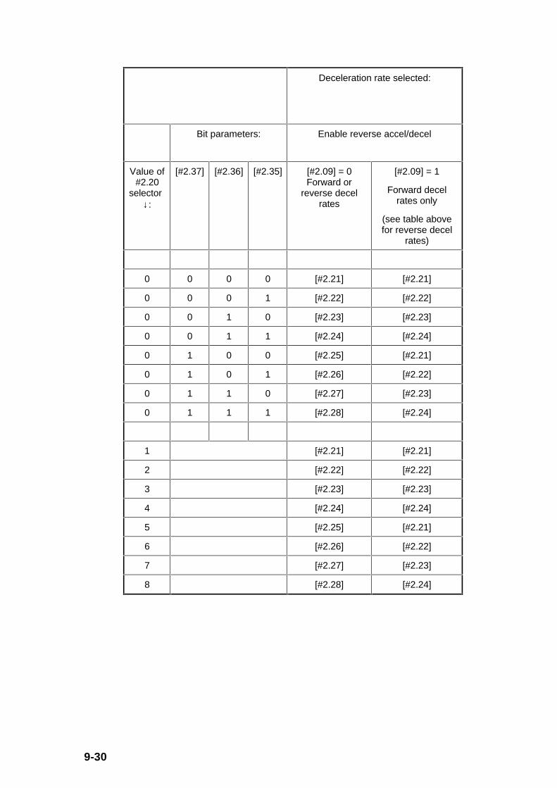
9-30
Deceleration rate selected:
Bit parameters: Enable reverse accel/decel
Value of#2.20
selector↓:
[#2.37] [#2.36] [#2.35] [#2.09] = 0Forward or
reverse decelrates
[#2.09] = 1
Forward decelrates only
(see table abovefor reverse decel
rates)
0 0 0 0 [#2.21] [#2.21]
0 0 0 1 [#2.22] [#2.22]
0 0 1 0 [#2.23] [#2.23]
0 0 1 1 [#2.24] [#2.24]
0 1 0 0 [#2.25] [#2.21]
0 1 0 1 [#2.26] [#2.22]
0 1 1 0 [#2.27] [#2.23]
0 1 1 1 [#2.28] [#2.24]
1 [#2.21] [#2.21]
2 [#2.22] [#2.22]
3 [#2.23] [#2.23]
4 [#2.24] [#2.24]
5 [#2.25] [#2.21]
6 [#2.26] [#2.22]
7 [#2.27] [#2.23]
8 [#2.28] [#2.24]

9-31
Selected presetfrequency reference
[#1.50] ↓:
9 1 [#2.21] [#2.21]
9 2 [#2.22] [#2.22]
9 3 [#2.23] [#2.23]
9 4 [#2.24] [#2.24]
9 5 [#2.25] [#2.21]
9 6 [#2.26] [#2.22]
9 7 [#2.27] [#2.23]
9 8 [#2.28] [#2.24]
When parameter #2.10 is set to 0 the acceleration rate selected depends on the stateof bit parameters #2.32 to #2.34, and similarly when #2.20 is set to 0 the decelerationrate selected depends on the state of bit parameters #2.35 to #2.37. (A similararrangement also applies when either #2.30 or #2.31 is set to 0, in that the reversedirection ramp rates are controlled by the #2.38 and #2.39 digital inputs, and, #2.40and #2.41 digital inputs respectively.) These bits are for control by digital inputssuch that ramp rates can be selected by external control. The ramp rate selecteddepends on the binary code generated by these bits as indicated in the above tables.
When parameter #2.10 or #2.20 is set to 9 the appropriate acceleration ordeceleration rate is automatically selected depending on the preset referenceselected. Thus an acceleration and/or deceleration rate can be programmed tooperate with each preset reference. Since the new ramp rate is selected with thenew reference, the acceleration or deceleration applies towards the selected preset.
If parameter #2.09 is set to 1 such that separate reverse accelerations anddecelerations are required, these parameters become forward acceleration anddeceleration selectors and are only able to select the four forward acceleration anddeceleration rates. If acceleration or deceleration rate 5 is selected, acceleration ordeceleration rate 1 will be used, and so on up to acceleration or deceleration 8.
9-32
#2.11 Accel 1/ forward accel 1 rate
#2.12 Accel 2/ forward accel 2 rate
#2.13 Accel 3/ forward accel 3 rate
#2.14 Accel 4/ forward accel 4 rate
#2.15 Accel 5/ reverse accel 1 rate
#2.16 Accel 6/ reverse accel 2 rate
#2.17 Accel 7/ reverse accel 3 rate
#2.18 Accel 8/ reverse accel 4 rate
#2.19 Jog acceleration rate
#2.21 Decel 1/ forward decel 1 rate
#2.22 Decel 2/ forward decel 2 rate
#2.23 Decel 3/ forward decel 3 rate
#2.24 Decel 4/ forward decel 4 rate
#2.25 Decel 5/ reverse decel 1 rate
#2.26 Decel 6/ reverse decel 2 rate
#2.27 Decel 7/ reverse decel 3 rate
#2.28 Decel 8/ reverse decel 4 rate
#2.29 Jog deceleration rate
Parameter type: RW, U
Adjustment range: 0.0 to 999.0
Units: s/100Hz
Default value: 5.0 (for #2.11 to #2.18)
0.2 (for #2.20 and #2.29)
10.0 (for #2.21 to #2.28)
The drive can be set up to either have eight acceleration and deceleration rateswhich are used in both the forward and reverse direction, or have four accelerationand four deceleration rates in each of the frequency directions, i.e. forwardacceleration, forward deceleration, reverse acceleration, and reverse deceleration.These 2 options are selectable by bit parameter #2.09. See the parameterdescription above for the selection process of the various ramp rates.
Parameters #2.19 and #2.29 are always used for jogging and must be set up for therequired jogging acceleration and deceleration rates.
All ramp rates are expressed as time in seconds for a change of 100Hz on the rampoutput. Therefore with a programmed ramp time of 5 seconds an acceleration rampoutput will reach 50Hz from 0Hz in 2.5 seconds.

9-33
#2.30 Reverse acceleration selector
#2.31 Reverse deceleration selector
(For parameter descriptions see Parameter #2.10 above.)
#2.32 Forward acceleration select bit 0
#2.33 Forward acceleration select bit 1
#2.34 Forward acceleration select bit 2
#2.35 Forward deceleration select bit 0
#2.36 Forward deceleration select bit 1
#2.37 Forward deceleration select bit 2
#2.38 Reverse acceleration select bit 0
#2.39 Reverse acceleration select bit 1
#2.40 Reverse deceleration select bit 0
#2.41 Reverse deceleration select bit 1
Parameter type: RO, Bit
Range: 0 or 1
Units: -
Default value: -
These bits are provided for control by logic input terminals for external rampselection (see parameter descriptions for #2.10, #2.20, #2.30 and #2.31 above).
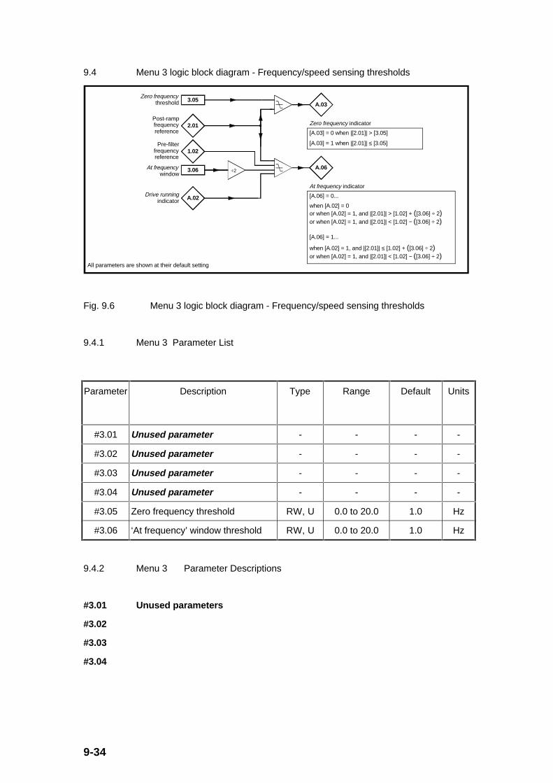
9-34
9.4 Menu 3 logic block diagram - Frequency/speed sensing thresholds
2.01Post-ramp frequency reference
3.05Zero frequency
threshold A.03
Zero frequency indicator
[A.03] = 0 when |[2.01]| > [3.05]
[A.03] = 1 when |[2.01]| ≤ [3.05]
3.06At frequency window
A.06
At frequency indicator
[A.06] = 0...
when [A.02] = 0or when [A.02] = 1, and |[2.01]| > [1.02] + ([3.06] ÷ 2)or when [A.02] = 1, and |[2.01]| < [1.02] − ([3.06] ÷ 2)
[A.06] = 1...
when [A.02] = 1, and |[2.01]| ≤ [1.02] + ([3.06] ÷ 2)or when [A.02] = 1, and |[2.01]| < [1.02] − ([3.06] ÷ 2)
÷2
All parameters are shown at their default setting
1.02Pre-filter
frequency reference
A.02Drive running indicator
Fig. 9.6 Menu 3 logic block diagram - Frequency/speed sensing thresholds
9.4.1 Menu 3 Parameter List
Parameter Description Type Range Default Units
#3.01 Unused parameter - - - -
#3.02 Unused parameter - - - -
#3.03 Unused parameter - - - -
#3.04 Unused parameter - - - -
#3.05 Zero frequency threshold RW, U 0.0 to 20.0 1.0 Hz
#3.06 ‘At frequency’ window threshold RW, U 0.0 to 20.0 1.0 Hz
9.4.2 Menu 3 Parameter Descriptions
#3.01 Unused parameters
#3.02
#3.03
#3.04

9-35
#3.05 Zero frequency threshold
Parameter type: RW, U
Adjustment range: 0.0 to 20.0
Units: Hz
Default value: 1.0
If the post-ramp frequency reference (#2.01) is at or below the level defined by thezero frequency threshold parameter, regardless of the direction, the zero frequencyindicator (#A.03) is set to 1, otherwise [#A.03] is 0.
#3.06 ‘At frequency’ window threshold
Parameter type: RW, U
Adjustment range: 0.0 to 20.0
Units: Hz
Default value: 1.0
The ‘at frequency’ window threshold defines the frequency window around the post-ramp frequency reference (#2.01) in which the 'at frequency' indication is given (i.e.[#A.06] = 1). The 'at frequency' window is thus defined as |[#2.01]| ± ([#3.06] / 2).

9-36
9.5 Menu 4 logic block diagram - Current control
4.08Torque
reference 2.01
Post-ramp frequency reference
5.06Motor − rated frequency
4.09Torque offset
4.10Select
torque offset
Torque-to-current conversion
5.07Motor − rated current
5.10Motor − rated power-factor
Current measurement
4.02
Load current (real/active component)
4.15
Motor thermal time-constant
4.16
Select motor protection mode
Overload detection
4.07
Current limit
4.19Motor thermal overload accumulator
A.17 Motor overload alarm
4.13
Current-control proportional gain
4.14
Current-control integral gain
A.09
Current-limit indicator
Menu 24.11 Select torque control
4.03
Percentage torque demand
All parameters are shown at their default setting
5.01Motor frequency
4.20
Percentage load
Current limiter
4.04
Percentage current demand
Current controller
0Hz
Drive current rating b.32
Fig. 9.7 Menu 4 logic block diagram - Current control

9-37
9.5.1 Menu 4 Parameter List
Parameter Description Type Range Default Units
#4.01 Unused parameter - - - -
#4.02 Load current (real/activecomponent)
RO, B, P 0.0 to + [#b.32]x [#5.10] x 1.5
- A
#4.03 Percentage torque demand RO, B, P 0.0 to + 150.0 x[#b.32] / [#5.07]
- %
#4.04 Percentage current demand RO, B, P 0.0 to + 150.0 x[#b.32] / [#5.07]
- %
#4.05 Unused parameter - - - -
#4.06 Unused parameter - - - -
#4.07 Current limit RW, U 0.0 to 150.0 x[#b.32] / [#5.07]
150.0 %
#4.08 Torque reference RW, B 0.0 to + 150.0 x[#b.32] / [#5.07]
0.0 %
#4.09 Torque offset RW, B 0.0 to + 150.0 x[#b.32] / [#5.07]
0.0 %
#4.10 Select torque offset RW, Bit 0/1 0 -
#4.11 Select torque control RW, Bit, P 0/1 0 -
#4.12 Unused parameter - - - -
#4.13 Current control proportional gain RW, U 0 to 250 50 -
#4.14 Current control integral gain RW, U 0 to 250 50 -
#4.15 Motor thermal time constant RW, U 0 to 250 89 s
#4.16 Select motor protection mode RW, Bit 0/1 0 -
#4.17 Unused parameter - - - -
#4.18 Unused parameter - - - -
#4.19 Motor thermal overloadaccumulator
RO, U, P 0.0 to 100.0 - %
#4.20 Percentage load RO, B, P 0.0 to 150.0 x[#b.32] / [#5.07]
- %
9-38
9.5.2 Menu 4 Parameter Descriptions
#4.01 Unused parameter
#4.02 Load current (real/active component)
Parameter type: RO, B, P
Range: 0.0 to + [#b.32] x [#5.10] x 1.5
Units: A
Default value: -
This parameter gives an approximate indication of the load current, or real/activecomponent of the current, as measured by the drive.
In a range between 15Hz and rated motor frequency ([#5.06]), the load current isnearly proportional to the given torque (T), i.e.
T ~ [#4.02] (or [#4.20])
Where: #4.20 is the percentage load
In the field-weakening region above motor rated frequency, torque decreasesinversely proportional to speed at the same active current, i.e. the followingrelationship applies:
T ~ [#4.02] x (motor rated frequency [#5.06])/(motor frequency [#5.01])

9-39
#4.03 Percentage torque demand
Parameter type: RO, B, P
Range: 0.0 to + 150.0 x [#b.32] / [#5.07]
Units: % (of torque)
Default value: -
The percentage torque demand is the sum of the torque reference (#4.08) and thetorque offset (#4.09), if enabled. The torque demand passes through a torque tocurrent conversion before being limited (by #4.07) and used as the (active) currentdemand (#4.04). Therefore, in torque control (i.e. [#4.11] = 1), the torque demandrepresents torque both below and above the machine base speed (#5.06, themachine rated frequency).
The units of the torque demand are % of rated torque. 100% rated torque is definedby the settings of the drive parameters as shown in the following example:
Motor rated current (#5.07) = 4A (set by user)
Motor rated power factor (#5.10) = 0.85 (set by user)
If the motor frequency (#5.01) is below the point where the voltage limit is reached(i.e. less than the motor rated frequency (#5.06)):
Rated load current (100% value of [ #4.02]) = [#5.07] x [#5.10] = 4 x 0.85 =3.4A
At 100% torque demand ([#4.03] = 100%), load current = [#4.02] = 3.4A
Percentage torque demand (#4.03) = Percentage current demand (#4.04)
If the motor frequency (#5.01) is above the motor rated frequency (#5.06), the torqueto current conversion is carried out by the following calculation:
Percentage current demand (#4.04) = Percentage torque demand [#4.03] x[#5.01] / [#5.06]
A positive value of torque demand indicates motoring torque in the forward direction,or regenerating torque in the reverse direction. A negative value indicatesregenerative torque in the forward direction and motoring torque in the reversedirection.
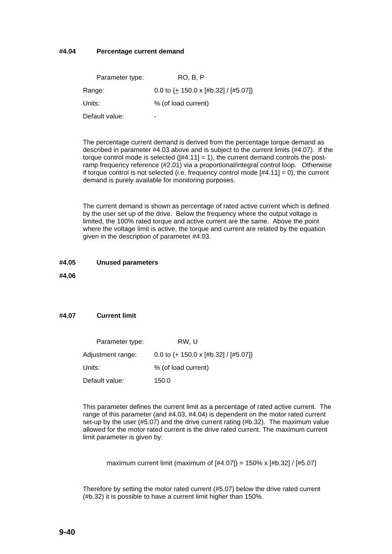
9-40
#4.04 Percentage current demand
Parameter type: RO, B, P
Range: 0.0 to + 150.0 x [#b.32] / [#5.07]
Units: % (of load current)
Default value: -
The percentage current demand is derived from the percentage torque demand asdescribed in parameter #4.03 above and is subject to the current limits (#4.07). If thetorque control mode is selected ([#4.11] = 1), the current demand controls the post-ramp frequency reference (#2.01) via a proportional/integral control loop. Otherwiseif torque control is not selected (i.e. frequency control mode [#4.11] = 0), the currentdemand is purely available for monitoring purposes.
The current demand is shown as percentage of rated active current which is definedby the user set up of the drive. Below the frequency where the output voltage islimited, the 100% rated torque and active current are the same. Above the pointwhere the voltage limit is active, the torque and current are related by the equationgiven in the description of parameter #4.03.
#4.05 Unused parameters
#4.06
#4.07 Current limit
Parameter type: RW, U
Adjustment range: 0.0 to + 150.0 x [#b.32] / [#5.07]
Units: % (of load current)
Default value: 150.0
This parameter defines the current limit as a percentage of rated active current. Therange of this parameter (and #4.03, #4.04) is dependent on the motor rated currentset-up by the user (#5.07) and the drive current rating (#b.32). The maximum valueallowed for the motor rated current is the drive rated current. The maximum currentlimit parameter is given by:
maximum current limit (maximum of [#4.07]) = 150% x [#b.32] / [#5.07]
Therefore by setting the motor rated current (#5.07) below the drive rated current(#b.32) it is possible to have a current limit higher than 150%.
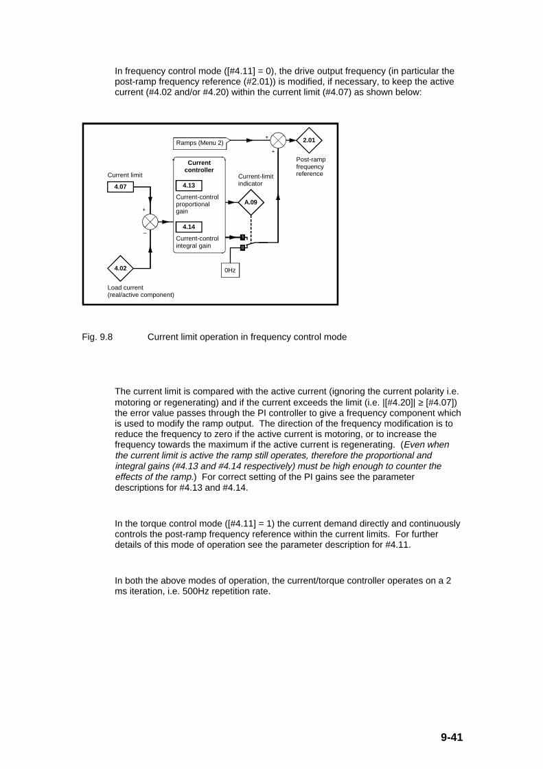
9-41
In frequency control mode ([#4.11] = 0), the drive output frequency (in particular thepost-ramp frequency reference (#2.01)) is modified, if necessary, to keep the activecurrent (#4.02 and/or #4.20) within the current limit (#4.07) as shown below:
A.09
Current-limit indicator
Ramps (Menu 2) 2.01
Post-ramp frequency reference
4.13
Current-control proportional gain
4.14
Current-control integral gain
4.07
Current limit
Current controller
0Hz4.02
Load current (real/active component)
Fig. 9.8 Current limit operation in frequency control mode
The current limit is compared with the active current (ignoring the current polarity i.e.motoring or regenerating) and if the current exceeds the limit (i.e. |[#4.20]| ≥ [#4.07])the error value passes through the PI controller to give a frequency component whichis used to modify the ramp output. The direction of the frequency modification is toreduce the frequency to zero if the active current is motoring, or to increase thefrequency towards the maximum if the active current is regenerating. (Even whenthe current limit is active the ramp still operates, therefore the proportional andintegral gains (#4.13 and #4.14 respectively) must be high enough to counter theeffects of the ramp.) For correct setting of the PI gains see the parameterdescriptions for #4.13 and #4.14.
In the torque control mode ([#4.11] = 1) the current demand directly and continuouslycontrols the post-ramp frequency reference within the current limits. For furtherdetails of this mode of operation see the parameter description for #4.11.
In both the above modes of operation, the current/torque controller operates on a 2ms iteration, i.e. 500Hz repetition rate.

9-42
#4.08 Torque reference
Parameter type: RW, B
Adjustment range: 0.0 to + 150.0 x [#b.32] / [#5.07]
Units: % (of load current)
Default value: 0.0
The torque reference is the main parameter that the user needs for torque control.
#4.09 Torque offset
Parameter type: RW, B
Adjustment range: 0.0 to + 150.0 x [#b.32] / [#5.07]
Units: % (of load current)
Default value: 0.0
The torque offset can be added to the torque reference (#4.08) but only if the selecttorque offset (#4.10) is set to 1.
#4.10 Select torque offset
Parameter type: RW, Bit
Adjustment range: 0 or 1
Units: -
Default value: 0
The select torque offset parameter must be set to a 1 if the torque offset (#4.09) is tobe added to the torque reference (#4.08).
9-43
#4.11 Select torque control
Parameter type: RW, Bit, P
Adjustment range: 0 or 1
Units: -
Default value: 0
If the select torque control parameter is set to 0 normal frequency control is used withan overriding current limit control. Further details are given in the parameterdescription #4.07.
If the select torque control parameter is set to 1 the current demand (#4.04) controlsthe post-ramp frequency reference (#2.01) with feedback from the actual currentmeasurement (#4.20) via the PI current controller. This provides continuous closedloop torque/current demand as illustrated in the Fig. 9.9 below. The current error ispassed through proportional and integral terms to give a frequency reference (#2.01)which is only limited by the maximum frequencies (in particular, #1.06, and #1.07depending on #1.08 with a 20% margin provided the frequencies are within the ULFrange). The drive direction is controlled by the required torque polarity as follows:
Torque (load)polarity
Frequencypolarity
Direction/Power flow
Positive Positive Forward (+ve)/ Motoring
Positive Negative Reverse (-ve)/ Regenerating
Negative Positive Forward (+ve)/ Regenerating
Negative Negative Reverse (-ve)/ Motoring
2.01
Post-ramp frequency reference
4.13
Current-control proportional gain
4.14
Current-control integral gain
Current controller
4.04
Current demand
4.20
Percentage load
Fig. 9.9 Torque control operation
In both the above modes of operation, the current/torque controller operates on a 2ms iteration, i.e. 500Hz repetition rate.

9-44
#4.12 Unused parameter
#4.13 Current control proportional gain
#4.14 Current control integral gain
Parameter type: RW, U
Adjustment range: 0 to 250
Units: -
Default value: 50
The proportional and integral current controller gains define the steady state andtransient response of the current controller whenever it is in operation. As describedin the parameter descriptions for #4.07 and #4.11 above, the current controller eitherprovides current limits or closed loop torque control by modifying the drive outputfrequency.
Although the default settings for the proportional and integral gains have beenchosen to give suitable gains for most applications it may be necessary for the userto adjust the gains for a more demanding application. The following is a guide tosetting the gains for different applications.
Current limit operation
The current controller will normally operate with an integral term only (i.e.proportional gain #4.13 set to 0), particularly below the point where field weakeningbegins (i.e. when |[#2.01]| ≤ [#5.06]). (The proportional term is inherent in the loop.)The integral gain must be large enough to counter the effect of the ramp which is stillactive even in current limit (i.e.[#A.09] = 1).
For example, if the drive is operating at constant frequency and is overloaded whenmotoring the current limit control will try to reduce the output frequency to reduce theload. At the same time, the ramp will try to increase the frequency back up to thedemand level. The integral gain needs to be set to a level to compensate for thiseffect. If the integral gain is increased too much, the first signs of instability willoccur when the motor frequency (#2.01) approaches the field weakening frequency(#5.06). This instability can be reduced by increasing the proportional gain.

9-45
Torque control operation
As for current limit operation, the current controller will normally operate with anintegral term only, particularly below the point where field weakening begins. Thefirst signs of instability will appear around base speed (#5.06), and can be reduced byincreasing the proportional gain. The controller tends to be less stable in torquecontrol mode than when it is used for current limiting. This is because motor loadhelps to stabilise the controller. Therefore under torque control, the motor may beoperating under light load, whereas under current limit control the motor is usuallyunder heavy load conditions unless the current limit (#4.07) is set to a low value.
#4.15 Motor thermal time constant
Parameter type: RW, U
Adjustment range: 0 to 250
Units: s
Default value: 89
The motor can be modelled thermally in a way that is equivalent to the electricalcircuit shown below, where the voltage across the capacitor represents the motortemperature and the square of the motor load current (#4.02) produces the current Iin the circuit.
Ι
C R Vc
Fig. 9.10 Thermal motor model where heat is represented by current
The response of this circuit to an input step of current I is:
vc = RI (1 - e-t/τ
)
where: vc is the capacitor voltage (equivalent to the motor temperature)
R is equivalent to the cooling effect of the motor
I is equivalent to the heating effect of the motor
t is time
τ is the RC time constant equivalent to the thermal time constant of the motor

9-46
Converting the above equation back to the thermal equivalent:
Motor temperature = Ki2 (1 - e
-t/τ)
where: K is a thermal constant
i is the motor active current relative to the rated motor active current (i.e. [#4.02]/[#5.07] x [#5.10]) (i2 because the heating effect is proportional to
current squared)
t is time
τ is the thermal time constant of the motor (given by #4.15)
The trip threshold within the drive motor thermal model software is defined as 105%of the motor rated active current (i.e. [#5.07] x [#5.10] x 1.05) on a continuous basis.Therefore, the drive will trip (when time t is very large) if the following is true:
Motor temperature to trip = i2 (1 - e
-t/τ) = ([#5.07] x [#5.10] x 1.05)
2
However, the drive is rated to give 150% rated current for 60 seconds before trippingon motor temperature. Therefore the motor thermal time constant time (τ or [#4.15])can be calculated for the motor thermal model:
Motor temperature to trip = i2 (1 - e
-t/τ) = ([#5.07] x [#5.10] x 1.50)
2 (1 - e
-
60/τ)
Solving the two above equations gives a value of τ or [#4.15] of 89.1 seconds.Hence, if [#4.15] is set to 89 seconds (default) the drive will trip in 60 seconds whenthe motor load current (#4.20) is at 150% rated current (150% of [#5.07] x [#5.10]).
If a different value for the motor thermal time constant is required it can bedetermined by any of the following 3 options:
1. Input [#4.15] directly as the motor manufacturers motor thermal time constant inseconds.
2. If a specified overload time (time to trip) and current level are known, (e.g. 60s at150% current), then:
[#4.15] = (-1) x (overload time) / ln[1 - (105%)2 / (current level in %)
2]

9-47
3. If the motor cooling time is known from a thermal overload trip situation to whenthe motor temperature is within 1% of the ambient temperature, then:
[#4.15] = (0.2) x (motor cooling time)
There are two possible modes of operation for motor thermal protection as definedby parameter #4.16. See parameter description below for further details.
#4.16 Select motor protection mode
Parameter type: RW, Bit
Adjustment range: 0 or 1
Units: -
Default value: 0
The motor protection mode bit provides two modes of operation for the motorthermal protection.
[#4.16] = 0 The drive will trip when the motor thermal protection triplevel is reached.
[#4.16] = 1 As the motor thermal protection trip level is approached, the current limit (#4.07) is automatically reduced to keep
the load current (#4.02) at the 100% rated current ([#5.07] x[#5.10]) so that the trip level is never reached. 5% hysteresis is included inthis case.
#4.17 Unused parameters
#4.18
#4.19 Motor thermal overload accumulator
Parameter type: RO, U, P
Adjustment range: 0.0 to 100.0
Units: % (of trip level)
Default value: -
The motor thermal overload accumulator gives an indication of motor temperature atany time as a percentage of the trip level (i.e. 100%).
9-48
The accumulator value is given as:
[#4.19] = ([#4.02])2 x (1 - e
-t/[#4.15]) x 100% / (1.05 x [#5.07] x [#5.10])
2
or: [#4.19] = ([#4.20]/100%)2 x (1 - e
-t/[#4.15]) x 100% / (1.05)
2
where: #4.02 is the load current (real/active component)
#4.20 is the percentage load
#4.15 is th motor thermal time constant
#5.07 is the Motor - rated current
#5.10 is the Motor - rated power factor
When the accumulator value (#4.19) reaches 100%, the drive will give an ‘Ixt’ trip (if[#4.16] = 0) or apply a restriction on the current limit (if [#4.16] = 1).
#4.20 Percentage load
Parameter type: RO, B, P
Range: 0.0 to + 150.0 x [#b.32] / [#5.07]
Units: % (of load current)
Default value: -
This parameter indicates the drive loading as a percentage of rated active current,where the 100% rated active current is [#5.07] x [#5.10]. Therefore:
[#4.20] = [#4.02] x 100% / ([#5.07] x [#5.10])
where: #4.02 is the load current (real/active component)
#5.07 is the Motor - rated current
#5.10 is the Motor - rated power factor
A positive value in this parameter indicates motoring load and a negative valueindicates a regenerating load.
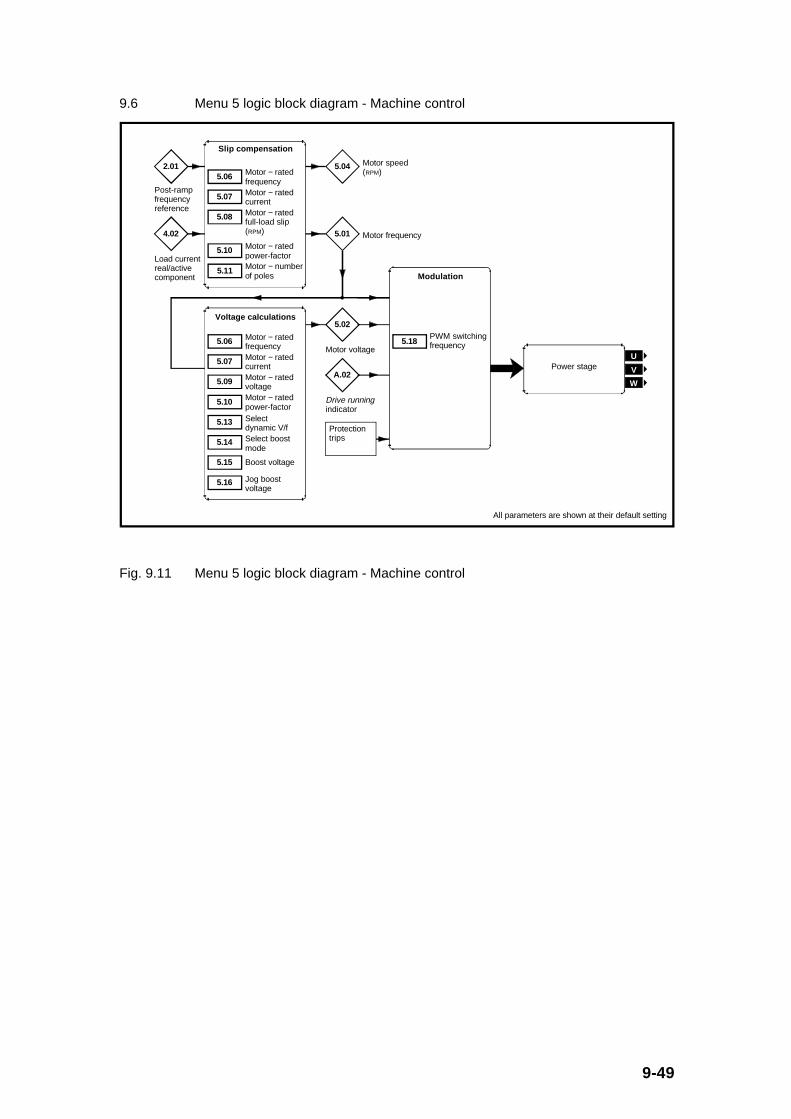
9-49
9.6 Menu 5 logic block diagram - Machine control
Protection trips
5.06 Motor − rated frequency
2.01
Post-ramp frequency reference
5.07 Motor − rated current
5.08 Motor − rated full-load slip (RPM)
5.10 Motor − rated power-factor
5.11 Motor − number of poles
Slip compensation
4.02
Load current real/active component
5.01 Motor frequency
5.04 Motor speed (RPM)
Voltage calculations
5.06 Motor − rated frequency
5.07 Motor − rated current
5.10 Motor − rated power-factor
5.13 Select dynamic V/f
5.14 Select boost mode
5.15 Boost voltage
5.16 Jog boost voltage
5.09 Motor − rated voltage
5.02
Motor voltage
A.02
Drive running indicator
5.18PWM switching frequency
Modulation
Power stageU
V
W
All parameters are shown at their default setting
Fig. 9.11 Menu 5 logic block diagram - Machine control

9-50
9.6.1 Menu 5 Parameter List
Parameter Description Type Range Default Units
#5.01 Motor frequency RO, B, P 0.0 to ≈ ±[#1.06] - Hz
#5.02 Motor voltage RO, U, P 0.0 to 100.0 - %
#5.03 Unused parameter - - - -
#5.04 Motor speed (rpm) RO, B, P 0.0 to ±9990 - rpm
#5.05 Unused parameter - - - -
#5.06 Motor - rated frequency RW, U 0.0 to ULF 50.0 or 60.0 Hz
#5.07 Motor - rated current RW, U 0.0 to FLC FLC A
#5.08 Motor - rated full load slip (rpm) RW, U 0 to 250 0 rpm
#5.09 Motor - rated voltage RW, U 0.0 to 100.0 100.0 %
#5.10 Motor - rated power factor RW, U, P 0.00 to 1.00 0.85 -
#5.11 Motor - number of poles RW, U, T, P 2P(0) to 8P(3) 4P(1) poles
#5.12 Unused parameter - - - -
#5.13 Select dynamic V/f RW, Bit 0/1 0 -
#5.14 Select boost mode RW, Bit, P 0/1 1 -
#5.15 Boost voltage RW, U 0.0 to 25.0 10.0 %
#5.16 Jog boost voltage RW, U 0.0 to 25.0 10.0 %
#5.17 General boost voltage RW, U 0.0 to 25.0 10.0 %
#5.18 PWM switching frequency RW, U, T, P 3 (0) to 12 (0) 3 (0) kHz
9-51
9.6.2 Menu 5 Parameter Descriptions
#5.01 Motor frequency
Parameter type: RO, B, P
Range: 0.0 to approximately ±[#1.06]
Units: Hz
Default value: -
This parameter gives the output frequency of the drive, i.e. the motor frequency.The value is calculated as follows: (i.e. the post-ramp reference plus the slipcompensation term)
[#5.01] = [#2.01] + [#5.08] x ([#5.11 i.e. the number of poles]/120) x ([#4.20]/100%)
where: #2.01 is the post-ramp frequency reference
#5.11 is the Motor - number of poles (use values of 2, 4, 6 or 8)
#5.08 is the Motor - rated full load slip (rpm)
#4.20 is the percentage load
Therefore the range of this parameter (#5.01) is the maximum magnitude ofparameters #1.06 and #1.07 plus whatever is added or subtracted for the slipcompensation.
#5.02 Motor voltage
Parameter type: RO, U, P
Range: 0.0 to 100.0
Units: % (of motor rated voltage (#5.09))
Default value: -
This parameter gives the output voltage of the drive, i.e. the motor voltage. Thevalue is
a percentage of the motor rated voltage (#5.09).

9-52
#5.03 Unused parameter
#5.04 Motor speed (rpm)
Parameter type: RO, B, P
Range: 0.0 to + 9990.
Units: rpm
Default value: -
This parameter gives the output speed of the motor, in rpm. The value is calculatedfrom the post- frequency reference (#2.01) as follows:
[#5.04] = 120 x [#2.01] / [#5.11 i.e. the number of poles 2, 4, 6 or 8]
The parameter value will be fairly accurate provided the slip compensation has beenset up correctly with the rated full load rpm parameter (#5.08).
Below 1,000rpm the parameter is displayed as rpm without a decimal place. Above999rpm the parameter is displayed as krpm or 1000's of rpm. For example,1,500rpm will be displayed as ‘1.50’ krpm.
#5.05 Unused parameter
#5.06 Motor - rated frequency
Parameter type: RW, U
Adjustment range: 0 to ULF, where:
ULF = 240Hz when [#5.18] = 3 (kHz),
ULF = 480Hz when [#5.18] = 6 (kHz),
ULF = 720Hz when [#5.18] = 9 (kHz),
ULF = 960Hz when [#5.18] = 12 (kHz)
Units: Hz
Default value: 50.0 (when #x.00 set to 533 followed by a ‘RESET’), or
60.0 (when #x.00 set to 544 followed by a ‘RESET’).

9-53
The motor rated frequency is used to define the voltage to frequency characteristicapplied to the drive (see parameter description for #5.14).
Therefore it is essential that this parameter is set for the particular motor used forcorrect operation of the drive.
#5.07 Motor - rated current
Parameter type: RW, U
Adjustment range: 0 to FLC (drive full load current [#b.32]), where:
FLC = 4.3A for DIN1220075A,
FLC = 3.0A for DIN1220055A,
FLC = 2.3A for DIN1220037A,
FLC = 1.5A for DIN1220025A
Units: A
Default value: FLC as above
The motor rated current should be set at the machine nameplate value for ratedcurrent.
This parameter value is used in the following parameter calculations:
Current limit, parameter #4.07
Motor thermal Ixt overload, parameter #4.15
Slip compensation, parameter #5.08
Dynamic V/f control, parameter #5.13
Auto boost, parameter #5.14
Therefore it is essential that this parameter is set for the particular motor used forcorrect operation of the drive.

9-54
#5.08 Motor - rated full load slip (rpm)
Parameter type: RW, U
Adjustment range: 0 to 250
Units: rpm
Default value: 0
The motor rated full load slip (in rpm) is used with the number of motor poles (#5.11)to calculate the rated slip of the induction motor in Hz.
motor rated slip (in Hz) = [#5.11 i.e. the number of poles 2, 4, 6 or 8] x[#5.08] / 120
The motor rated slip (in Hz) is used to calculate the frequency adjustment requiredto compensate for slip from the following equation:
slip compensation (in Hz) = [motor rated slip (in Hz)] x [active current] /[rated active current]
= [motor rated slip (in Hz)] x [#4.02] / [#5.07] x [#5.10]
where: #5.07 is the Motor - rated current
#5.10 is the Motor - rated power factor
If parameter #5.08 is set to 0 slip compensation is disabled.
If slip compensation is required #5.08 should be set from the motor nameplate valuefor rated speed as follows:
[#5.08] = [Rated frequency] x 120 / [number of motor poles] - [Rated motor full loadspeed]
= [#5.06] x 120 / [#5.11 i.e. the number of poles 2, 4, 6 or 8] - [Motornameplate full load speed]
Example: For a 50Hz 4-pole machine rated at 1,450rpm
[#5.08] = 50 x 120 / 4 - 1450
= 50 rpm

9-55
Sometimes it will be necessary to adjust parameter #5.08 when the drive iscommissioned because the motor nameplate value could be inaccurate. Slipcompensation will operate correctly both below base speed (#5.06) and above basespeed, in the field weakening region. However, by changing this parameter value,the motor can either be over or under compensated for slip as necessary (i.e. theshaft speed can be made to increase or decrease with mechanical load asnecessary).
Slip compensation will not alter the frequency direction defined by the post-rampfrequency reference.
#5.09 Motor - rated voltage
Parameter type: RW, U
Adjustment range: 0.0 to 100.0
Units: % (of input supply voltage)
Default value: 100.0
The motor rated voltage should be set up according to the motor nameplate ratedvoltage. In particular:
[#5.09] = 100% x [motor nameplate voltage] / [drive input supply voltage]
Example: Motor used : 50Hz, 230V in delta, 400V in star connection
Supply voltage available: 240VAC
Settings: The motor is operated in a delta connection where:
[#5.09] = (Motor voltage) x 100%/ (Supply voltage)
= 230 x 100%/240
= 96%
It is essential that this parameter is set for the particular motor used for correctoperation of the drive and other related voltage parameters, such as dynamic V/f,boost, etc.

9-56
#5.10 Motor - rated power factor
Parameter type: RW, U, P
Adjustment range: 0.00 to 0.85 x [#b.32]/[#5.07] (with a maximum of 1.00)
Units: -
Default value: 0.85
The motor rated power factor is used in conjunction with the motor rated current(#5.07) to calculate the rated active current (100% value for #4.02) (i.e. [100% of#4.02] = [#5.07] x [#5.10]).. The rated active current is used extensively to controlthe drive.
It is therefore essential that this parameter is set for the particular motor used forcorrect operation of the drive and all related current parameters.
#5.11 Motor - number of poles
Parameter type: RW, U, T, P
Adjustment range: 2P (0), 4P (1), 6P (2), or 8P (3)
Units: Number of poles
Default value: 4P (1)
Set this parameter to the number of poles (not the number of pole pairs) for themotor being used, with the aid of the text options provided.
#5.11 Setting
(Display)
Setting via
Serial
comms
Description
2P 0 2 Motor poles
4P 1 4 Motor poles
6P 2 6 Motor poles
8P 3 8 Motor poles
It is essential that this parameter is set for the particular motor used for correctoperation of the drive and all related speed and slip parameters.
Example: An induction motor has a rated speed of 1,440rpm and a ratedfrequency of 50Hz. Therefore, the motor is 4-pole, and this parameter is set to 4P(or 1 using serial comms).

9-57
#5.12 Unused parameter
#5.13 Select dynamic V/f
Parameter type: RW, Bit
Adjustment range: 0 or 1
Units: -
Default value: 0
If the select dynamic V/f bit is set to 0, the V/f characteristic is fixed.
Setting the select dynamic V/f bit to a 1 enables the dynamic voltage to frequencymode of operation. This mode is intended for applications where power loss shouldbe kept to a minimum under light load conditions and motor audible noise is to beminimised. The voltage to frequency ratio is modified with load as follows:
If: |active current| < 0.7 x [rated active current]
(|[#4.02]| < 0.7 x [#5.07] x [#5.10], or, |[#4.20]| < 70%)
where: #4.02 is the load current (real/active component
#5.07 is the Motor - rated current
#5.10 is the Motor - rated power factor
#4.20 is the percentage load
Then:
V/f ratio = [normal V/f ratio] x 0.5 + |[#4.20]|/ (140%)
Otherwise if:
|active current| ≥ 0.7 x [rated active current] , or, |[#4.20]| ≥ 70%)
Then:
V/f ratio = [normal V/f ratio]

9-58
Output voltage (V)
Output frequency (Hz)
AC supply voltage
Increasing load(ie. |[4.20]| > 0%
or
Fig. 9.12 Volt/Hz characteristic for fixed and dynamic V/f settings
#5.14 Select boost mode
Parameter type: RW, Bit, P
Adjustment range: 0 or 1
Units: -
Default value: 1
The select boost mode enables the selection of a fixed boost V/f characteristic whenset to 0, and an auto boost characteristic when set to 1. In both cases the followingV/f characteristic is used.

9-59
Motor voltage
Output frequency Hz
(% of [#5.09])
Boost voltage %
[#5.06]
100%
50%
[#5.06] ÷ 2
Fig. 9.13 Volt/Hz characteristic for varying boost settings
If fixed boost is selected ([#5.14] = 0) the voltage boost is that set by the user inparameter #5.15 (or #5.16 when jogging). In auto boost mode ([#5.14] = 1) thevoltage boost is load dependent and is set to the boost parameter value (#5.15 or#5.16) when the load (|[#4.20]|) is at 100%. For more or less load the voltage boostis directly scaled, e.g. 50% load will produce a voltage boost equal to 50% of #5.15or #5.16.
#5.15 Boost voltage
Parameter type: RW, U
Adjustment range: 0.0 to 25.0
Units: % (of motor rated voltage (#5.09))
Default value: 10.0
The boost voltage level for the voltage frequency characteristic during normaloperation (not jogging) is defined by this parameter. The boost level is relevant forboth fixed boost ([#5.14] = 0), and auto boost operation ([#5.14] = 1). The voltagefrequency characteristic is further defined in parameter descriptions #5.13 and #5.14.See Fig. 9.13 above for further details.
9-60
The actual boost voltage (in volts) is:
[#5.15]/100% x [#5.09]/100% x (input supply voltage)
where: #5.09 is the Motor - rated voltage
#5.16 Jog boost voltage
Parameter type: RW, U
Adjustment range: 0.0 to 25.0
Units: % (of motor rated voltage (#5.09))
Default value: 10.0
If the jog preset speed is active ([#1.13] = 1), the jog boost voltage parameter is usedinstead of the normal boost level set by parameter #5.15 for defining the boostvoltage level for the V/f characteristic. See Fig. 9.13 and parameter description #5.15above for further details.
The actual jog boost voltage (in volts) is:
[#5.16]/100% x [#5.09]/100% x (input supply voltage)
where: #5.09 is the Motor - rated voltage

9-61
#5.17 General boost voltage
Parameter type: RW, U
Adjustment range: 0.0 to 25.0
Units: % (of motor rated voltage (#5.09))
Default value: 8.0
The general boost voltage level defines the amount of lad dependent boost appliedacross the frequency range (subject to the maximum output voltage limit of 100% of[#5.09]). The voltage frequency characteristic is further defined in parameterdescriptions #5.13, #5.14 and #5.15. See Fig. 9.13 above for further details.
The actual general boost voltage (in volts) is:
[#5.17]/100% x [#5.09]/100% x |[#4.20]|/100% x (input supply voltage)
where: #5.09 is the Motor - rated voltage
#4.20 is the percentage load
#5.18 PWM switching frequency
Parameter type: RW, U, T, P
Adjustment range: 3 (0), 6 (1), 9 (2), or 12 (3)
Units: kHz
Default value: 3 (0)
This parameter sets the available PWM switching frequencies of the Dinverter. Inparticular:
#5.18 Setting
(Display)
Setting via
Serial
comms
Description
3 0 3kHz PWM switching frequency (actually 2.9kHz)
6 1 6kHz PWM switching frequency (actually 5.8kHz)
9 2 9kHz PWM switching frequency (actually 8.8kHz)
12 3 12kHz PWM switching frequency (actually
11.7kHz)

9-62
The output frequency of the drive ([#5.01]) is limited by the switching frequencyselected as follows:
Switchingfrequency
Maximum output frequency(Upper limit frequency -
ULF)
3kHz 240Hz
6kHz 480Hz
9kHz 720Hz
12kHz 960Hz
The maximum output frequency for each switching frequency is known as the UpperLimit Frequency and is used as the maximum range of some parameters. It shouldbe noted that if a maximum speed limit (#1.06 or #1.07) is set to an upper limitfrequency, there will be no head room for the drive to increase frequency above thislevel to affect slip compensation. If slip compensation is required the user mustensure that a switching frequency is selected which allows the output frequency torise enough to allow the compensation.

9-63
9.7 Menu 6 logic block diagram - Drive sequencer and run-time clock
6.30Sequencing
bit 0
6.31Sequencing bit 1
6.32Sequencing
bit 2
6.33Sequencing
bit 3
6.34Drive enable
6.01Stop mode selector
6.02Auto-start mode
6.04 Sequencing mode selector
6.05 Minimum jog time
6.15Output-stage enable
6.06Injection braking level
6.07Injection braking time
Sequencer
A.32External trip
A.33Drive reset
Logic 1
6.11
Enable keypad RUN switch
6.12
Enable keyapd STOP switch
6.13
Enable keypad FWD/REV switch
6.14
Disable auto-keypad switches
1.11
Final frequency reference on
1.12
Reverse selected
1.13
Jog selected
6.20~ 6.23
Run-time log (when [A.02] = 1)
RUN
STOP/ RESET
FWD/REV
RESET
A.20~ A.29
Last trip log
All parameters are shown at their default setting
1.49
Selected frequency reference (when [1.49] = 4)
A.02
Drive running indicator
Fig. 9.14 Menu 6 logic block diagram - Drive sequencer and run-time clock

9-64
9.7.1 Menu 6 Parameter List
Parameter Description Type Range Default Units
#6.01 Stop mode selector RW, U, T, P CSt (0) to dcI (3) rP (1) -
#6.02 Auto start mode selector RW, U, T, P diS (0) to Pd.d (2) diS (0) -
#6.03 Unused parameter - - - -
#6.04 Sequencing mode selector RW, U, P 0 to 4 2 -
#6.05 Minimum jog time RW, U 0.0 to 25.0 0.0 s
#6.06 Injection braking level RW, U 0.0 to 25.0 10.0 %
#6.07 Injection braking time RW, U 0.0 to 25.0 5.0 s
#6.08 Unused parameter - - - -
#6.09 Unused parameter - - - -
#6.10 Unused parameter - - - -
#6.11 Enable keypad run switch RW, Bit 0/1 0 -
#6.12 Enable keypad stop switch RW, Bit 0/1 0 -
#6.13 Enable keypad fwd/rev switch RW, Bit 0/1 0 -
#6.14 Unused parameter - - - -
#6.15 Output stage enable RW, Bit 0/1 1 -
#6.16 Unused parameter - - - -
#6.17 Unused parameter - - - -
#6.18 Unused parameter - - - -
#6.19 Unused parameter - - - -
#6.20 Run time log: years RO, U, S, P 250 - years
#6.21 Run time log: days RO, U, S, P 364 - days
#6.22 Run time log: hours RO, U, S, P 23 - hours
#6.23 Run time log: minutes RO, U, S, P 59 - minutes
#6.24 Unused parameter - - - -
#6.25 Unused parameter - - - -
#6.26 Unused parameter - - - -
#6.27 Unused parameter - - - -
#6.28 Unused parameter - - - -
#6.29 Unused parameter - - - -
#6.30 Sequencing bit 0 RW, Bit 0/1 - -
#6.31 Sequencing bit 1 RW, Bit 0/1 - -
#6.32 Sequencing bit 2 RW, Bit 0/1 - -
#6.33 Sequencing bit 3 RW, Bit 0/1 - -
#6.34 Drive enable RW, Bit 0/1 - -

9-65
9.7.2 Menu 6 Parameter Descriptions
#6.01 Stop mode selector
Parameter type: RW, U, T, P
Adjustment range: CSt (0), rP (1), rP.I (2), or, dcI (3)
Units: -
Default value: rP (1)
This parameter has 4 settings:
#6.01 Setting
(Display)
Setting via
Serial
comms
Description
CSt 0 Coast stop
rP 1 Ramp stop
rP.I 2 Ramp stop with 1 second DCinjection
dcI 3 Timed DC injection braking stop
In the ‘CSt’ stopping mode, after applying a stop command, the output IGBT stage isdisabled immediately and the motor coasts to a standstill. The output IGBT stage isdisabled for a minimum of 1 second before it can be enabled again.
In the ‘rP’ stopping mode, after applying a stop command, the drive ramps down tozero frequency according to the deceleration rate. The output stage is disabled onesecond after reaching 0Hz. With a large inertia motor load, the motor can still beturning at low speed after this time, depending on the boost settings.
In the ‘rP.I’ stopping mode, after applying a stop command, the drive ramps down tozero frequency according to the deceleration rate. On reaching 0Hz, a DC voltage isswitched onto the motor for one second (a fixed boost value set via #6.06), whichcreates a holding torque. With large inertia motor loads, #6.06 can be set to ensurethat the motor is stationary after the 1 second DC injection period.
In the ‘dcI’ stopping mode, DC injection starts immediately after a stop command isgiven. The DC injection voltage is set via #6.06, and the DC injection time is setwith #6.07.

9-66
#6.02 Auto start mode selector
Parameter type: RW, U, T, P
Adjustment range: diS (0), ALS (1), or Pd.d (2)
Units: -
Default value: diS (0)
This parameter has 3 settings:
#6.02 Setting
(Display)
Setting via
Serial
comms
Description
diS 0 Auto start disabled
ALS 1 Auto start mode always enabled
Pd.d 2 Auto start mode enabled butdependent on running condition onsupply removal
In the ‘diS’ auto start mode the drive will never automatically start at power up,unless the sequencing control inputs are configured to do so. (The ‘diS’ mode willonly have an effect on sequencing modes 0 and 1 as described below in Parameter#6.04).
In the ‘ALS’ auto start mode the drive will always start at power up (or following anundervoltage trip) only in sequencing modes 0 or 1, provided the Drive enable bitparameter #6.34 is set to 1.
In the ‘Pd.d’ auto start mode the drive may start at power up (or following anundervoltage trip) only in sequencing modes 0 or 1, provided the Drive enable bitparameter #6.34 is set to 1. In this power down dependent mode the drive will onlystart at power up if it was running (i.e. not stopping) when power was last removedfrom the drive.
#6.03 Unused parameter
9-67
#6.04 Sequencing mode selector
Parameter type: RW, U, P
Adjustment range: 0 to 4
Units: -
Default value: 2
The drive sequencer controls the operation of the drive in terms of deciding theoperating states from the various inputs. There are a number of operating stateswhich are indicated on the display in the status mode. These various states aredescribed in Section 10.1.
The drive sequencer has 5 modes of operation which are controlled by the followinginputs: (however, keypad control (i.e.[#1.49] = 4) overrrides these sequencingmodes)
Sequencing bit 0 (#6.30)
Sequencing bit 1 (#6.31)
Sequencing bit 2 (#6.32)
Sequencing bit 3 (#6.33)
Drive enable (#6.34)
Output stage enable (#6.15)
‘RUN’ key (on keypad)
‘STOP/RESET’ key (on keypad)
‘FWD/REV’ key (on keypad)
The first 5 bit parameters above can be controlled from any input terminal or overthe serial interface. The output stage enable bit (#6.15) must be set to a 1 for driveoperation, otherwise if set to 0 will disable drive operation. In a similar fashion, thedrive must not be in a ‘trP’ state as this will not allow drive operation either. SeeSection 9.11 for details. The function of each of these 5 bits depends on which ofthe 5 sequencing modes is selected. The sequencing modes are:
Sequencing mode (i.e. value of #6.04) Operating type interface
0 ‘Momentary pushbutton’ type interface
1 ‘Mentor’ drive type interface
2 ‘Wire-proof’ type interface
3 PLC (Programmable logic controller)type interface
4 ‘Wire-proof’ PLC type interface

9-68
In addition there is also a sequencing mode when the keypad frequency reference isselected:
Sequencing mode (i.e. value of#1.49)
Operating type interface
4 ‘Keypad’ type interface
The operation of each of the 5 control bits mentioned above for each of thesequencing modes is as follows:
Sequencingmode →:
Control bits↓:
[#6.04] = 0
‘Momentary
pushbutton’
[#6.04] = 1
‘Mentor’drive
[#6.04] = 2
‘Wire-proof’
[#6.04] = 3
PLC
[#6.04] = 4
‘Wire-proof’ PLC
[#1.49] = 4
‘Keypad’
[#6.30]Sequencing
bit 0
Run(latching)
Runforward
(latching)
Runforward
Run Runforward
Nofunction
[#6.31]Sequencing
bit 1
Jog Jogforward
Jog Jog Jog Nofunction
[#6.32]Sequencing
bit 2
Reverse Runreverse
(latching)
Runreverse
Reverse Runreverse
Nofunction
[#6.33]Sequencing
bit 3
Nofunction
Jogreverse
Nofunction
Nofunction
Nofunction
Nofunction
[#6.34] Driveenable
Runpermit/not
stop
Runpermit/not
stop
Enable Nofunction
Nofunction
Enable

9-69
Further details about each of the 4 sequencing modes and the action of the abovecontrol bits are detailed below.
‘Momentary pushbutton’ Sequencing mode 0 ([#6.04] = 0)
Bit value →:
Control bits ↓:
0 1
[#6.30] Sequencing bit 0
Run (latching)
No action (Momentarilyonly)
Start/run
[#6.31] Sequencing bit 1
Jog
No jogging
(stop)
Jog
[#6.32] Sequencing bit 2
Reverse
Forward
(Running orjogging)
Reverse
(Running orjogging)
[#6.33] Sequencing bit 3
No function
- -
[#6.34] Drive enable
Run permit/not stop
Stop Allow to run
Sequencing bits 0 and 2 are overridden by the keypad ‘RUN’ and ‘FWD/REV’
keys, respectively, if they are enabled via #6.11 and #6.13. The ‘STOP/RESET’ key can stop the drive if it is enabled via #6.12 except if jogging. A jog command willonly be accepted in the ‘rdy’ ready state. Start/run commands override jogcommands.

9-70
‘Mentor’ drive Sequencing mode 1 ([#6.04] = 1)
Bit value →:
Control bits ↓:
0 1
[#6.30] Sequencing bit 0
Run forward (latching)
No action (Momentarilyonly)
Run forward
[#6.31] Sequencing bit 1
Jog forward
No joggingforward
Jog forward
[#6.32] Sequencing bit 2
Run reverse (latching)
No action (Momentarilyonly)
Run reverse
[#6.33] Sequencing bit 3
Jog reverse
No joggingreverse
Jog reverse
[#6.34] Drive enable
Run permit/not stop
Stop Allow to run
The ‘RUN’ key can also latch a run state if it is enabled via #6.11, and the
‘FWD/REV’ key can change direction if it is enabled via #6.13 (unless one of thesequencing bits is being held in logic state 1, in which case the sequencing bit has
priority). The ‘STOP/RESET’ key can also stop the drive if it is enabled via#6.12, and a run or jog condition is not being forced by the sequencing bits. Any jogcommand received will only be accepted in the ‘rdy’ ready state. Run commandsoverride jog commands.
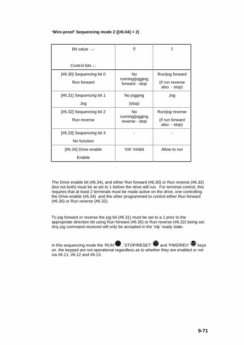
9-71
‘Wire-proof’ Sequencing mode 2 ([#6.04] = 2)
Bit value →:
Control bits ↓:
0 1
[#6.30] Sequencing bit 0
Run forward
Norunning/joggingforward - stop
Run/jog forward
(if run reversealso - stop)
[#6.31] Sequencing bit 1
Jog
No jogging
(stop)
Jog
[#6.32] Sequencing bit 2
Run reverse
Norunning/joggingreverse - stop
Run/jog reverse
(if run forwardalso - stop)
[#6.33] Sequencing bit 3
No function
- -
[#6.34] Drive enable
Enable
‘Inh’ Inhibit Allow to run
The Drive enable bit (#6.34), and either Run forward (#6.30) or Run reverse (#6.32)(but not both) must be at set to 1 before the drive will run. For terminal control, thisrequires that at least 2 terminals must be made active on the drive, one controllingthe Drive enable (#6.34) and the other programmed to control either Run forward(#6.30) or Run reverse (#6.32).
To jog forward or reverse the jog bit (#6.31) must be set to a 1 prior to theappropriate direction bit using Run forward (#6.30) or Run reverse (#6.32) being set.Any jog command received will only be accepted in the ‘rdy’ ready state.
In this sequencing mode the ‘RUN’ , ‘STOP/RESET’ and ‘FWD/REV’ keyson the keypad are not operational regardless as to whether they are enabled or notvia #6.11, #6.12 and #6.13.

9-72
PLC Sequencing mode 3 ([#6.04] = 3)
Bit value →:
Control bits ↓:
0 1
[#6.30] Sequencing bit 0
Run
Norunning/jogging -
stop
Start/run
[#6.31] Sequencing bit 1
Jog
No jogging
(stop)
Jog
[#6.32] Sequencing bit 2
Reverse
Forward
(Running orjogging)
Reverse
(Running orjogging)
[#6.33] Sequencing bit 3
No function
- -
[#6.34] Drive enable
No function
- -
To jog forward or jog reverse the jog bit (#6.31) must be set to a 1 followed by therun bit ([#6.30] = 1) and the appropriate direction selected by #6.32. A jog commandwill only be accepted in the ‘rdy’ ready state.
In this sequencing mode the ‘RUN’ , ‘STOP/RESET’ and ‘FWD/REV’ keyson the keypad are not operational regardless as to whether they are enabled or notvia #6.11, #6.12 and #6.13.
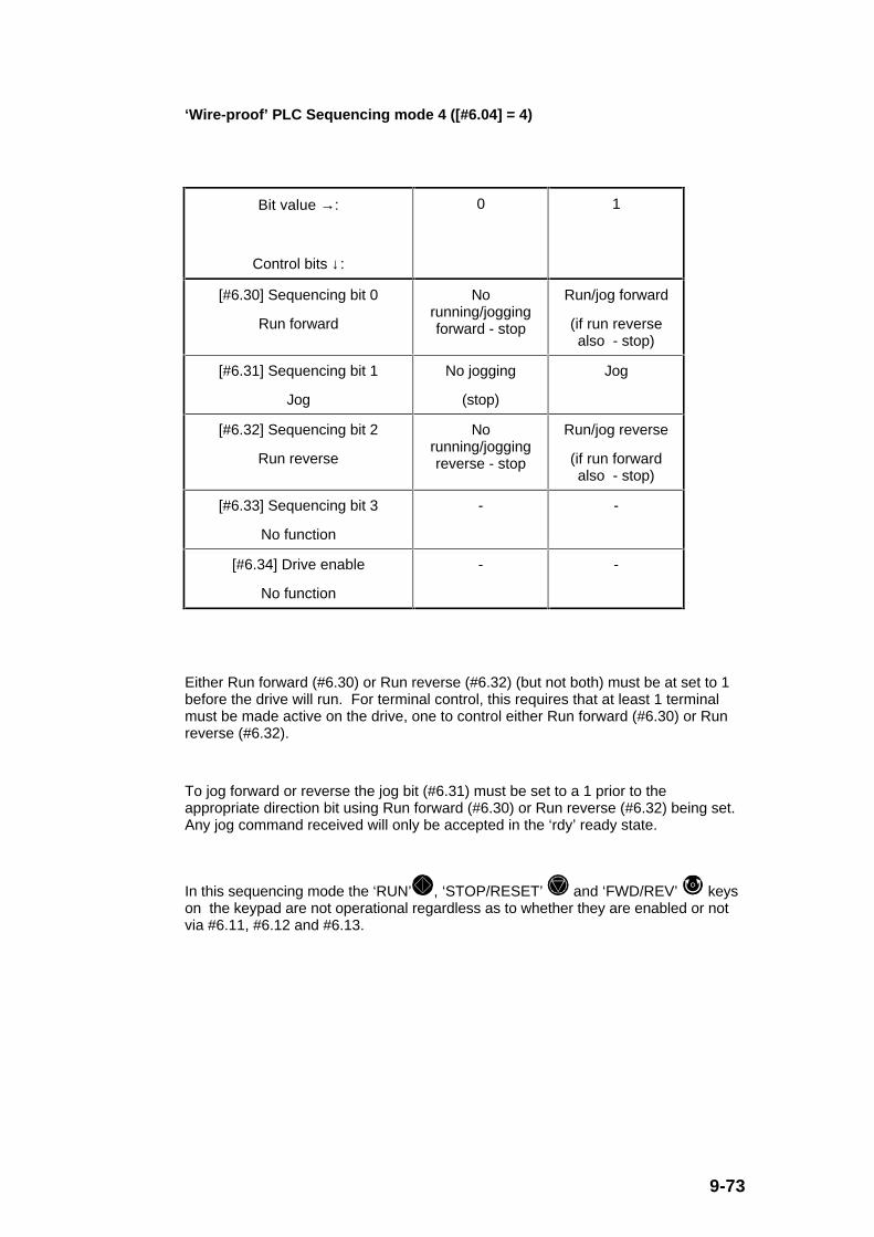
9-73
‘Wire-proof’ PLC Sequencing mode 4 ([#6.04] = 4)
Bit value →:
Control bits ↓:
0 1
[#6.30] Sequencing bit 0
Run forward
Norunning/joggingforward - stop
Run/jog forward
(if run reversealso - stop)
[#6.31] Sequencing bit 1
Jog
No jogging
(stop)
Jog
[#6.32] Sequencing bit 2
Run reverse
Norunning/joggingreverse - stop
Run/jog reverse
(if run forwardalso - stop)
[#6.33] Sequencing bit 3
No function
- -
[#6.34] Drive enable
No function
- -
Either Run forward (#6.30) or Run reverse (#6.32) (but not both) must be at set to 1before the drive will run. For terminal control, this requires that at least 1 terminalmust be made active on the drive, one to control either Run forward (#6.30) or Runreverse (#6.32).
To jog forward or reverse the jog bit (#6.31) must be set to a 1 prior to theappropriate direction bit using Run forward (#6.30) or Run reverse (#6.32) being set.Any jog command received will only be accepted in the ‘rdy’ ready state.
In this sequencing mode the ‘RUN’ , ‘STOP/RESET’ and ‘FWD/REV’ keyson the keypad are not operational regardless as to whether they are enabled or notvia #6.11, #6.12 and #6.13.

9-74
‘Keypad’ Sequencing mode ([#1.49] = 4)
Bit value →:
Control bits ↓:
0 1
[#6.30] Sequencing bit 0
No function
- -
[#6.31] Sequencing bit 1
No function
- -
[#6.32] Sequencing bit 2
No function
- -
[#6.33] Sequencing bit 3
No function
- -
[#6.34] Drive enable
Enable
‘Inh’ Inhibit Allow to run
The Drive enable (#6.34) must be at set to 1 before the drive will run.
In this sequencing mode the ‘RUN’ , ‘STOP/RESET’ and ‘FWD/REV’ keyson the keypad are operational regardless as to whether they are enabled or not via#6.11, #6.12 and #6.13.

9-75
#6.05 Minimum jog time
Parameter type: RW, U
Adjustment range: 0.0 to 25.0
Units: s
Default value: 0.0
The minimum jog time can be used to define a minimum jog period such that themotor will rotate by a fixed amount when a jog command (shorter than the minimumperiod) is received.
This parameter is not operational in the ‘Wire-proof’, PLC and ‘Wire-proof’ PLCsequencing modes 2, 3 and 4 because removing the jog command whilst leaving therun command active causes the drive to select the running mode instead of thedesired jogging mode.
#6.06 Injection braking level
Parameter type: RW, U
Adjustment range: 0.0 to 25.0
Units: % (of motor rated voltage (#5.09))
Default value: 10.0
The injection braking level defines the boost voltage level used for injection brakingwhen selected via the relevant stop modes (i.e. [#6.01] = 2 or 3).
#6.07 Injection braking time
Parameter type: RW, U
Adjustment range: 0.0 to 25.0
Units: s
Default value: 5.0
The injection braking time defines the time used for injection braking when selectedvia the ‘dcI’ stop mode (i.e. [#6.01] = 3).

9-76
#6.08 Unused parameters
#6.09
#6.10
#6.11 Enable keypad run switch
#6.12 Enable keypad stop switch
#6.13 Enable keypad fwd/rev switch
Parameter type: RW, Bit
Adjustment range: 0 or 1
Units: -
Default value: 0
The 3 keypad enable switches (#6.11, #6.12 and #6.13) enable the run function of
the ‘RUN’ key, the stop function of the ‘STOP/RESET’ key and the
forward/reverse function of the ‘FWD/REV’ key respectively when each bit is setto a 1.
However, when the keypad frequency reference is selected (i.e. [#1.49] = 4), then the3 switches are enabled regardless of the state of the 3 keypad enable switches(#6.11, #6.12 and #6.13).
#6.14 Unused parameter
#6.15 Output stage enable
Parameter type: RW, Bit
Adjustment range: 0 or 1
Units: -
Default value: 1
The output stage enable parameter must be set to a 1 for the drive to run, regardlessof the operation of the drive sequencer explained in parameter description #6.04above.
Setting output stage enable(#6.15) to a 0 will immediately disable the drive andindicate ‘inh’ on the display in Status Mode.
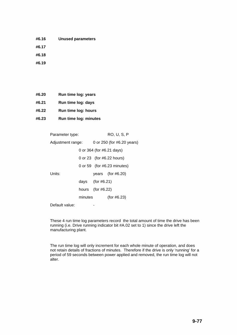
9-77
#6.16 Unused parameters
#6.17
#6.18
#6.19
#6.20 Run time log: years
#6.21 Run time log: days
#6.22 Run time log: hours
#6.23 Run time log: minutes
Parameter type: RO, U, S, P
Adjustment range: 0 or 250 (for #6.20 years)
0 or 364 (for #6.21 days)
0 or 23 (for #6.22 hours)
0 or 59 (for #6.23 minutes)
Units: years (for #6.20)
days (for #6.21)
hours (for #6.22)
minutes (for #6.23)
Default value: -
These 4 run time log parameters record the total amount of time the drive has beenrunning (i.e. Drive running indicator bit #A.02 set to 1) since the drive left themanufacturing plant.
The run time log will only increment for each whole minute of operation, and doesnot retain details of fractions of minutes. Therefore if the drive is only ‘running’ for aperiod of 59 seconds between power applied and removed, the run time log will notalter.

9-78
#6.24 Unused parameters
#6.25
#6.26
#6.27
#6.28
#6.29
#6.30 Sequencing bit 0
#6.31 Sequencing bit 1
#6.32 Sequencing bit 2
#6.33 Sequencing bit 3
#6.34 Drive enable
Parameter type: RW, Bit
Adjustment range: 0 or 1
Units: -
Default value: -
The drive sequencer uses these 5 bits as inputs. This allows the user to programmethe various digital terminal inputs according to the application needs. (See Section9.9 for further details about assigning digital inputs to these bits.)
The function of the 5 sequencing bits is fully explained in the parameter descriptionfor #6.04 above.
Although these parameters are R/W, they are not stored at power down. Every timethe drive is powered up they will be all be set to 0, until controlled by the variousdigital inputs or serial comms etc. .
9-79
9.8 Menu 7 logic block diagram - Analogue inputs and outputs
A2
Analog input 1−10V ~ +10V
Analog-to- digital converter
7.06
Analog input 1 mode selector
7.01
Analog input 1
7.08
Analog input 1 scale factor
x(-1)
1.36
Any non-bit (RW and RO)
parameter that is not protected
?.??
C5
C4
Analog-to- digital converter / Transceiver
7.09
Invert analog input 1
7.10
Analog input 1 destination selector
7.11
Analog input 2 mode selector
Analog input 2 0 ~ 20mA / RS485
7.02
Analog input 2
7.12
Analog input 2 scale factor
x(-1)
1.37
Any non-bit (RW and RO)
parameter that is not protected
?.??
7.13
Invert analog input 2
7.14
Select analog input 2 destination parameter
Termination resistor (100Ω)
Ι
5.01
Any non-bit parameter (RW or RO)
?.??
7.19
Analog output 1 source selector
7.20
Analog output 1 scale factor
7.21
Analog output 1 mode selector(0 ~ 10V or 0 ~ 20mA)
C2
All parameters are shown at their default setting
Analog output 1
7.04
Heatsink temperature
Fig. 9.15 Menu 7 logic block diagram - Analogue inputs and outputs

9-80
9.8.1 Menu 7 Parameter List
Parameter Description Type Range Default Units
#7.01 Analogue input 1 (A2) RO, B, P 0.0 to +100.0 - %
#7.02 Analogue input 2 (C4/C5) RO, U, P 0.0 to 100.0 - %
#7.03 Unused parameter - - - -
#7.04 Heatsink temperature RO, U, P 0 to 100 - oC
#7.05 Unused parameter - - - -
#7.06 Analogue input 1 (A2) modeselector
RW, U, T,P
ULt (0) or th (1) ULt (0) -
#7.07 Unused parameter - - - -
#7.08 Analogue input 1 (A2) scale factor RW, U 0.00 to 2.50 1.00 -
#7.09 Invert analogue input 1 (A2) RW, Bit 0/1 0 -
#7.10 Analogue input 1 (A2) destinationselector
RW, U, R,P
(#) 0.00 to E.50 (#)1.36 (#)
#7.11 Analogue input 2 (C4/C5) modeselector
RW, U, T,P
ANS (0) to th (5) ANS (0) -
#7.12 Analogue input 2 (C4/C5) scalefactor
RW, U 0.00 to 2.50 1.00 -
#7.13 Invert analogue input 2 (C4/C5) RW, Bit 0/1 0 -
#7.14 Analogue input 2 (C4/C5)destination selector
RW, U, R,P
(#) 0.00 to E.50 (#)1.37 (#)
#7.15 Unused parameter - - - -
#7.16 Unused parameter - - - -
#7.17 Unused parameter - - - -
#7.18 Unused parameter - - - -
#7.19 Analogue output 1 (C2) sourceselector
RW, U, P (#) 0.00 to E.50 (#)5.01 (#)
#7.20 Analogue output 1 (C2) scalefactor
RW, U 0.00 to 2.50 1.00 -
#7.21 Analogue output 1 (C2) modeselector
RW, U, T,P
ULt(0) to 4.20(2)
ULt(0) -

9-81
9.8.2 Menu 7 Parameter Descriptions
#7.01 Analogue input 1 (A2)
Parameter type: RO, B, P
Range: 0.0 to +100.0
Units: % (of input 1 (A2) full scale i.e. +10V)
Default value: -
This analogue input 1 (A2) parameter gives the level of the analogue signal presentat terminal A2. Analogue input 1 is a bipolar voltage input having a range of -10V to+10V which is converted to ±100.0%, the resolution is 10 bit plus sign (i.e. + or -0.1V). The sample time is every 16ms.
#7.02 Analogue input 2 (C4/C5)
Parameter type: RO, U, P
Range: 0.0 to 100.0
Units: % (of input 2 (C4/C5) full scale i.e. +20mA)
Default value: -
This analogue input 2 (C4/C5) parameter gives the level of the differential analoguesignal between terminals C5 and C4. Analogue input 2 is a unipolar current inputhaving a range of 0 to 20mA. Using parameter #7.11 (analogue input 2 modeselector), the drive can be programmed to convert the measured current to any oneof the following ranges:
0 - 20 mA ([#7.11] = 1) 0mA = 0%, 20mA = 100%
20 - 0 mA ([#7.11] = 2) 0mA = 100%, 20mA = 0%
4 - 20 mA ([#7.11] = 3) 4mA = 0%, 20mA = 100%
20 - 4 mA ([#7.11] = 4) 4mA = 100%, 20mA = 0%
The measurement resolution is 10 bit (i.e. 0.2mA). The sample time is every 16ms.
#7.03 Unused parameter
9-82
#7.04 Heatsink temperature
Parameter type: RO, U, P
Range: 0 to 100
Units: oC
Default value: -
This parameter displays the temperature currently being measured on the heat sink.If this parameter reaches 100ºC the drive will trip (‘Oh2’ on the display in Trip Mode)and will not allow a reset until the temperature falls below 90ºC. The alarm level(‘hot’ on the display) is at 95°C and above.
#7.05 Unused parameter
#7.06 Analogue input 1 (A2) mode selector
Parameter type: RW, U, T, P
Adjustment range: ULt (0) or th (1)
Units: -
Default value: ULt (0)
The Terminal A2 analogue input can be configured either as a voltage input (default)or as a motor thermistor input. The setting of this parameter configures the terminalfor the required mode.
#7.06 Setting
(Display)
Setting via
Serial
comms
Description
ULt 0 Terminal A2 accepts -10V to +10V analoguevoltage input
th 1 Terminal A2 accepts motor thermistor input,when configured as below:

9-83
0V common
+10V reference
Analog input
15kΩ ±10%
1 to 6 motor thermistors
Fig. 9.16 Optional motor thermistor input arrangement for Terminal A2
The motor thermistor can be from 1 to 6 250Ω standard motor thermistors connectedin series. The drive will trip (‘th’ trip code) when the thermistor resistance is ≥ 3.3kΩ,and a reset value ≤ 1.8kΩ.
#7.07 Unused parameter
9-84
#7.08 Analogue input 1 (A2) scale factor
#7.12 Analogue input 2 (C4/C5) scale factor
Parameter type: RW, U
Adjustment range: 0.00 to 2.50
Units: -
Default value: 1.00
These parameters can be used to scale an input if required. However in most casesit is not necessary as each input is automatically scaled such that for 100.0% inputthe destination parameter (defined by #7.10 and #7.14) will be at maximum.
The resulting scaled values are calculated as follows:
[Destination parameter defined by #7.10] = [#7.01] x [#7.08] in %
( = [#[#7.10]])
where: full scale of destination parameter relates to a value of100%
#7.01 is the Analogue input 1 (A2)
[Destination parameter defined by #7.14] = [#7.02] x [#7.12] in %
( = [#[#7.14]])
where full scale of destination parameter relates to a value of 100%
#7.02 is the Analogue input 2 (C4/C5)
#7.09 Invert analogue input 1 (A2)
#7.13 Invert analogue input 2 (C4/C5)
Parameter type: RW, Bit
Adjustment range: 0 or 1
Units: -
Default value: 0
These parameters can be used to invert (i.e. multiply input scaling result by -1) theinput references.

9-85
#7.10 Analogue input 1 (A2) destination selector
#7.14 Analogue input 2 (C4/C5) destination selector
Parameter type: RW, U, R, P
Adjustment range: (#) 0.00 to E.50
Units: (#) (i.e. #(menu number).(parameter number))
Default value: (#)1.36 for #7.10
(#)1.37 for #7.14
These parameters define the destination of the relevant analogue inputs. Thereforethese parameters can be used to select certain internal parameters which need to becontrolled by an analogue input. For the defaults setting given above:
[#7.10] = 1.36 Analogue input 1 routed to parameter #1.36 (Analogue frequencyreference 1)
[#7.14] = 1.37 Analogue input 2 routed to parameter #1.37 (Analogue frequencyreference 2)
Only non-bit parameters (parameter types RW and RO) which are not protected(parameter type P) can be controlled by analogue inputs. If a non valid parameter isthe destination of an analogue input, the input is not routed anywhere.
9-86
#7.11 Analogue input 2 (C4/C5) mode selector
Parameter type: RW, U, T, P
Adjustment range: ANS (0), 0.20 (1), 20.0 (2), 4.20 (3), 20.4 (4), or th (5)
Units: -
Default value: ANS (0)
Analogue input 2 (C4/C5) can be configured for different input signal types (includingserial communications). The setting of this parameter configures the terminals forthe required mode of operation as follows:
#7.11 Setting
(Display)
Setting via
Serial
comms
Description
ANS 0 RS485 ANSI serial comms port active
0.20 1 Current input 0 to 20mA (20mA full scale)
20.0 2 Current input 20 to 0mA (0mA full scale)
4.20 3 Current input 4 to 20mA (20mA full scale)
20.4 4 Current input 20 to 4mA (4mA full scale)
th 5 Motor thermistor input, see Fig. 9.17 below for
arrangement
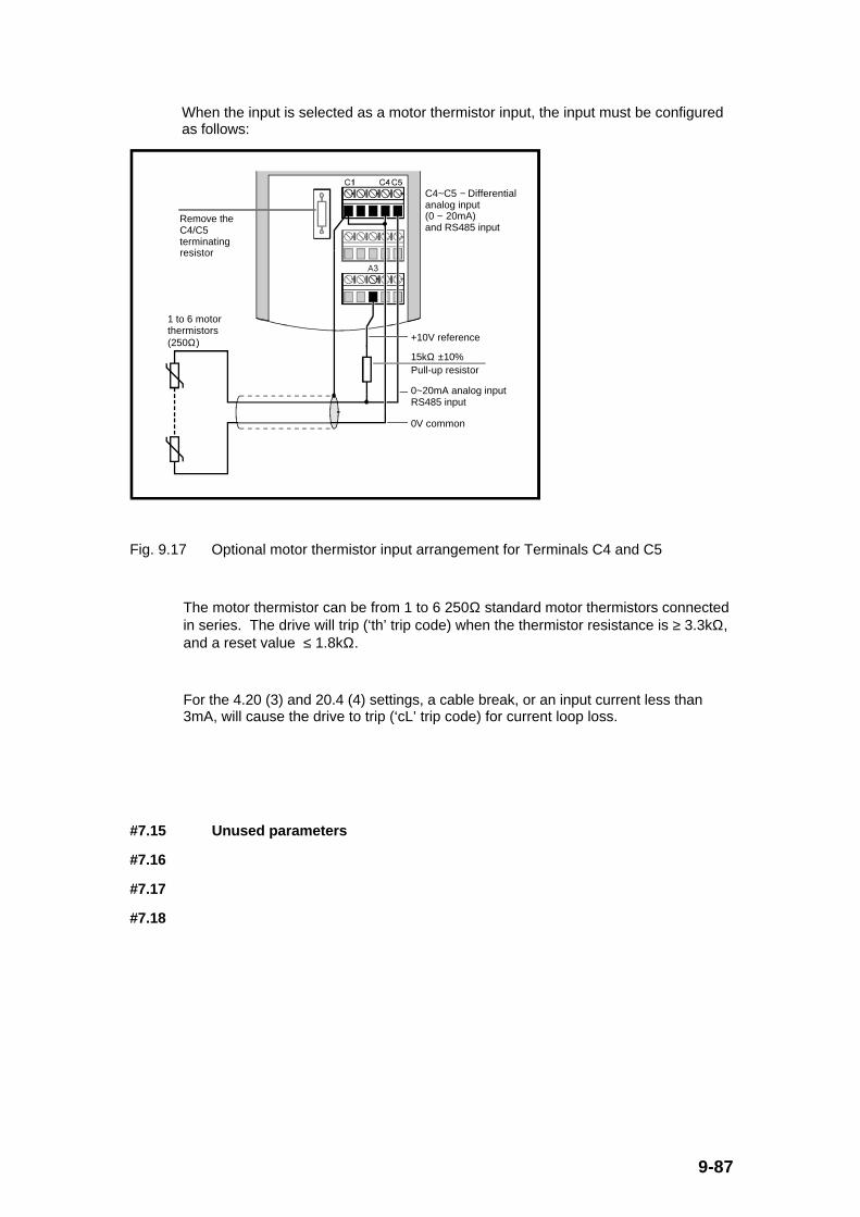
9-87
When the input is selected as a motor thermistor input, the input must be configuredas follows:
15kΩ ±10%
+10V reference
0V common
0~20mA analog inputRS485 input
1 to 6 motor thermistors(250Ω)
Remove the C4/C5 terminating resistor
Pull-up resistor
C4~C5 − Differential analog input (0 ~ 20mA) and RS485 input
Fig. 9.17 Optional motor thermistor input arrangement for Terminals C4 and C5
The motor thermistor can be from 1 to 6 250Ω standard motor thermistors connectedin series. The drive will trip (‘th’ trip code) when the thermistor resistance is ≥ 3.3kΩ,and a reset value ≤ 1.8kΩ.
For the 4.20 (3) and 20.4 (4) settings, a cable break, or an input current less than3mA, will cause the drive to trip (‘cL’ trip code) for current loop loss.
#7.15 Unused parameters
#7.16
#7.17
#7.18

9-88
#7.19 Analogue output 1 (C2) source selector
Parameter type: RW, U, P
Adjustment range: (#) 0.00 to E.50
Units: (#) (i.e. #(menu number).(parameter number))
Default value: (#)5.01
This parameter defines the source of the relevant value to be output as an analoguesignal at terminal C2. Therefore this parameter can be used to enable certaininternal parameters to be monitored as an analogue output. For the default settinggiven above:
[#7.19] = 5.01 Parameter #5.01 (Motor frequency) value routed to Analogue output1 (C2)
Only non-bit parameters (parameter types RW and RO) can be programmed as asource. If a non valid parameter is programmed as the source, the output value is 0.If a bipolar parameter is programmed as a source, the absolute value is fed to theanalogue output.
#7.20 Analogue output 1 (C2) scale factor
Parameter type: RW, U
Adjustment range: 0.00 to 2.50
Units: -
Default value: 1.00
This parameter can be used to scale an output if required. However in most cases itis not necessary as the analogue output is automatically scaled such that for themaximum value of the source parameter, the analogue output will be at full scale(100.0%).
The resulting scaled value is calculated as follows:
[Percentage analogue output at C2] = [Source parameter defined by #7.19 in %] x[#7.20]
= [#[#7.19]] x [#7.20]
where full scale of source parameter relates to a value of 100%
For default settings:
0V at analogue output (C2) when source parameter defined by #7.19 ([#5.01 - Motorfrequency] = 0Hz)
+10V at analogue output (C2) when source parameter defined by #7.19 ([#5.01 -Motor frequency] ) is at maximum (50Hz) as defined by the parameter #1.06(maximum frequency ).
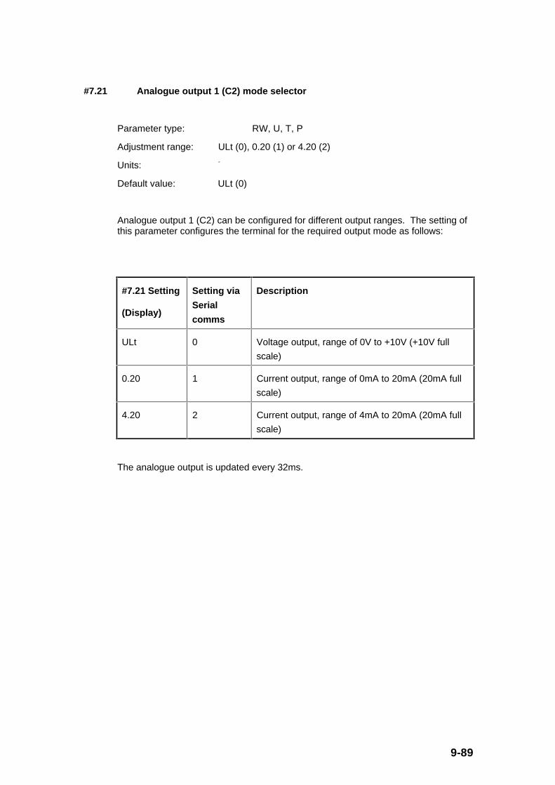
9-89
#7.21 Analogue output 1 (C2) mode selector
Parameter type: RW, U, T, P
Adjustment range: ULt (0), 0.20 (1) or 4.20 (2)
Units: -
Default value: ULt (0)
Analogue output 1 (C2) can be configured for different output ranges. The setting ofthis parameter configures the terminal for the required output mode as follows:
#7.21 Setting
(Display)
Setting via
Serial
comms
Description
ULt 0 Voltage output, range of 0V to +10V (+10V full
scale)
0.20 1 Current output, range of 0mA to 20mA (20mA full
scale)
4.20 2 Current output, range of 4mA to 20mA (20mA full
scale)
The analogue output is updated every 32ms.
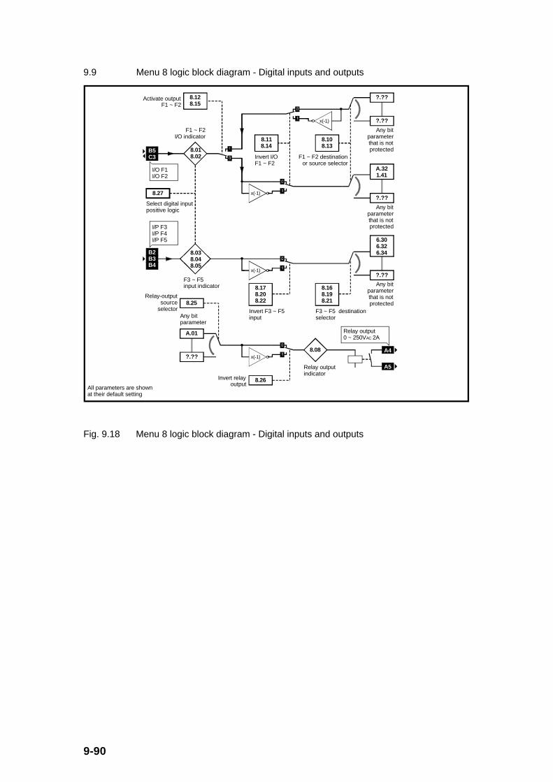
9-90
9.9 Menu 8 logic block diagram - Digital inputs and outputs
8.128.15
Activate output F1 ~ F2
8.27
Select digital input positive logic
B5C3
8.018.02
F1 ~ F2 I/O indicator
8.038.048.05
F3 ~ F5 input indicator
x(-1)
?.??
?.??
Any bit parameter that is not protected
x(-1)
8.118.14
Invert I/O F1 ~ F2
8.108.13
F1 ~ F2 destination or source selector
A.321.41
?.??
Any bit parameter that is not protected
8.168.198.21
F3 ~ F5 destination selector
B2B3B4
x(-1)?.??
Any bit parameter that is not protected
6.306.326.34
8.178.208.22
Invert F3 ~ F5 input
x(-1)
A.01
Any bit parameter
?.??
8.26Invert relay output
8.25Relay-output
source selector
8.08
Relay output indicator
All parameters are shown at their default setting
I/O F1I/O F2
I/P F3I/P F4I/P F5
A4
Relay output 0 ~ 250VAC 2A
A5
Fig. 9.18 Menu 8 logic block diagram - Digital inputs and outputs

9-91
9.9.1 Menu 8 Parameter List
Parameter Description Type Range Default Units
#8.01 Digital input F1/output 1 (B5)indicator
RO, Bit, P 0/1 - -
#8.02 Digital input F2/output 2 (C3)indicator
RO, Bit, P 0/1 - -
#8.03 Digital input F3 (B2) indicator RO, Bit, P 0/1 - -
#8.04 Digital input F4 (B3) indicator RO, Bit, P 0/1 - -
#8.05 Digital input F5 (B4) indicator RO, Bit, P 0/1 - -
#8.06 Unused parameter - - - -
#8.07 Unused parameter - - - -
#8.08 Relay output (A4/A5) indicator RO, Bit, P 0/1 - -
#8.09 Unused parameter - - - -
#8.10 F1 input (B5) destination/outputsource selector
RW, U, R*,P (* only if
input)
(#) 0.00 toE.50
(#)A.32 (#)
#8.11 Invert F1 input/output (B5) RW, Bit 0/1 1 -
#8.12 Activate output 1 (B5) RW, Bit, R 0/1 0 -
#8.13 F2 input (C3) destination/outputsource selector
RW, U, R*,P (* only if
input)
(#) 0.00 toE.50
(#)1.41 (#)
#8.14 Invert F2 input/output (C3) RW, Bit 0/1 0 -
#8.15 Activate output 2 (C3) RW, Bit, R 0/1 0 -
#8.16 F3 input (B2) destination selector RW, U, R,P
(#) 0.00 toE.50
(#)6.30 (#)
#8.17 Invert F3 input (B2) RW, Bit 0/1 0 -
#8.18 Unused parameter - - - -
#8.19 F4 input destination (B3) selector RW, U, R,P
(#) 0.00 toE.50
(#)6.32 (#)
#8.20 Invert F4 input (B3) RW, Bit 0/1 0 -
#8.21 F5 input destination (B4) selector RW, U, R,P
(#) 0.00 toE.50
(#)6.34 (#)
#8.22 Invert F5 input (B4) RW, Bit 0/1 0 -
#8.23 Unused parameter - - - -
#8.24 Unused parameter - - - -
#8.25 Relay output (A4/A5) sourceselector
RW, U, P (#) 0.00 toE.50
(#)A.01 (#)
#8.26 Invert relay output (A4/A5) RW, Bit 0/1 0 -
#8.27 Select digital input(B2/B3/B4/B5/C3) positive logic
RW, Bit, R,P
0/1 0 -
9-92
9.9.2 Menu 8 Parameter Descriptions
Summary of digital inputs and outputs
Terminals B5 and C3 (F1 and F2 respectively) can be independently set up as eitherdigital inputs or outputs, whilst terminals B2, B3 and B4 (F3, F4 and F5 respectively)can be digital inputs only. All digital inputs and/or outputs are completelyprogrammable in terms of their function. Digital inputs are sampled, and digitaloutputs updated, every 8ms. The relay output (A4/A5) is updated every 8ms.
#8.01 Digital input F1/output 1 (B5) indicator
#8.02 Digital input F2/output 2 (C3) indicator
Parameter type: RO, Bit, P
Range: 0 or 1
Units: -
Default value: -
These 2 parameters indicate the input state of the respective terminal if they are setup as inputs (i.e. B5 is an input if [#8.12] = 0, C3 is an input if [#8.15] =0), or theoutput state if they are set up as outputs (i.e. B5 is an output if [#8.12] = 1, C3 is anoutput if [#8.15] =1).
For digital inputs, the value of the parameter is as follows:
0 when: [#8.27] = 0 and input high (inactive), or
[#8.27] = 1 and input low (inactive).
1 when [#8.27] = 0 and input low (active), or
[#8.27] = 1 and input high (active).
where: #8.27 is select digital input (B2/B3/B4/B5/C3) positive logic
For digital outputs, the value of the parameter will cause the following:
0 disables the current sinking capability (independent of #8.27)
1 enables the current sinking capability (independent of #8.27)

9-93
#8.03 Digital input F3 (B2) indicator
#8.04 Digital input F4 (B3) indicator
#8.05 Digital input F5 (B4) indicator
Parameter type: RO, Bit, P
Range: 0 or 1
Units: -
Default value: -
These 3 parameters indicate the input state of the respective terminals.
The value of the parameter is as follows:
0 when: [#8.27] = 0 and input high (inactive), or
[#8.27] = 1 and input low (inactive).
1 when [#8.27] = 0 and input low (active), or
[#8.27] = 1 and input high (active).
where: #8.27 is select digital input (B2/B3/B4/B5/C3) positive logic
#8.06 Unused parameters
#8.07
#8.08 Relay output (A4/A5) indicator
Parameter type: RO, Bit, P
Range: 0 or 1
Units: -
Default value: -
This parameters indicates the output state of the control relay (Normally Opencontact) across terminals A4/A5.
The value of the parameter indicates the following:
0 control relay de-energised, contact across A4/A5 open (independentof #8.27)
1 control relay energised, contact across A4/A5 closed (independent of #8.27)
where: #8.27 is select digital input (B2/B3/B4/B5/C3) positive logic
9-94
#8.09 Unused parameter
#8.10 F1 input (B5) destination/output source selector
#8.13 F2 input (C3) destination/output source selector
#8.16 F3 input (B2) destination selector
#8.19 F4 input (B3) destination selector
#8.21 F5 input (B4) destination selector
#8.25 Relay output (A4/A5) source selector
Parameter type: RW, U, R, P except:
RW, U, P for #8.25 (and, #8.10 and #8.13 if outputs)
Adjustment range: (#) 0.00 to E.50
Units: (#) (i.e. #(menu number).(parameter number))
Default value: (#)A.32 for #8.10
(#)1.41 for #8.13
(#)6.30 for #8.16
(#)6.32 for #8.19
(#)6.34 for #8.21
(#)A.01 for #8.25
The above destination selector parameters (excluding #8.25) define the destinationof the relevant digital input signal. Therefore these parameters can be used tocontrol certain internal bit parameters which need to be controlled. Only bitparameters (Bit) which are not protected (P) can be controlled by programmabledigital inputs (i.e. destination selector parameters). If a non valid parameter isselected as the destination the input is not routed anywhere.
For the default settings:
[#8.10] = A.32 - Digital input B5, (B5 is an input if [#8.12] = 0), value routedto External Trip bit (#A.32)
[#8.13] = 1.41 - Digital input C3, (C3 is an input if [#8.15] = 0), value routedto Select analogue frequency reference 2 bit (#1.41)
[#8.16] = 6.30 - Digital input B2 value routed to Sequencing bit 0 (#6.30)which in sequencing mode 2 (i.e. [#6.04] = 2) corresponds toRun Forward
[#8.19] = 6.32 - Digital input B3 value routed to Sequencing bit 2 (#6.32)which in sequencing mode 2 (i.e. [#6.04] = 2) corresponds toRun Reverse
9-95
[#8.21] = 6.34 - Digital input B4 value routed to Drive enable bit (#6.34) which in sequencing mode 2 (i.e. [#6.04] = 2) corresponds to Enable
where: #8.12 is the activate output 1 (B5)
#8.15 is the activate output 2 (C3)
The above source selector parameters (i.e. #8.25, #8.10 when [#8.12] = 1, and #8.13when [#8.15] = 1) define the source of the relevant bit value to be output as a digitalsignal at the relevant terminals. Therefore these parameters can be used to enablecertain internal bit parameters to be monitored as digital outputs. Only bitparameters (Bit) can be selected as the source for a programmable digital output. Ifa non valid parameter is selected as the source the output terminal will be in theinactive state and the relay will be de-energised.
For the default settings:
[#8.25] = A.01 - The drive healthy indicator bit value [#A.01] is routed to therelay output
#8.11 Invert F1 input/output (B5)
#8.14 Invert F2 input/output (C3)
#8.17 Invert F3 input (B2)
#8.20 Invert F4 input (B3)
#8.22 Invert F5 input (B4)
#8.26 Invert relay output (A4/A5)
Parameter type: RW, Bit
Adjustment range: 0 or 1
Units: -
Default value: 1 for #8.11
0 for #8.14, #8.17, #8.20, #8.22 and #8.26

9-96
These invert parameters enable an inversion of a digital input (or output) bit value.
For digital inputs:
Input bit value(e.g. [#8.03])
Invert bit value(e.g. [#8.17])
Destination bit value(e.g. [#6.30])
0 0 0
1 0 1
0 1 1
1 1 0
For digital outputs:
Source bitvalue (e.g.
[#A.01])
Invert bit value(e.g. [#8.26])
Output bitvalue (e.g.
[#8.25])
0 0 0
1 0 1
0 1 1
1 1 0
#8.12 Activate output 1 (B5)
#8.15 Activate output 2 (C3)
Parameter type: RW, Bit, R
Adjustment range: 0 or 1
Units: -
Default value: 0
These activate output bit parameters enable the Input/Output terminals (B5 and C3only) to be configured as either an input or an output. A bit value of 1 sets therelevant terminal as an output and a 0 as an input.
9-97
#8.18 Unused parameters
#8.23
#8.24
#8.27 Select digital input (B2/B3/B4/B5/C3) positive logic
Parameter type: RW, Bit, R, P
Adjustment range: 0 or 1
Units: -
Default value: 0
The select digital input positive logic bit sets the digital input to be either configuredfor positive logic or negative logic. In default settings (i.e.[#8.27] = 0) the digitalinputs are configured for negative logic which requires the digital inputs to be pulledlow (i.e. connected to 0V Common) to activate the input (i.e. [digital input] = 1).Otherwise the digital input will float high (i.e. [digital input] = 0).
When the select digital input positive logic bit is set to 1, the digital inputs areconfigured for positive logic which requires the digital inputs to be pulled high (i.e.connected to +24V) to activate the input (i.e. [digital input] = 1). Otherwise the digitalinput will float low (i.e. [digital input] = 0).

9-98
9.10 Menu 9 logic block diagram - Programmable logic and motorised potentiometer
9.01
Logic-function output indicator
x(-1)
0.00
Any bit parameter
?.??
9.05
Invert logic-function input 1
9.04
Logic-function input 1 source selector
x(-1)
0.00
Any bit parameter
?.??
9.07
Invert logic-function input 2
9.06
Logic-function input 2 source selector
x(-1)
9.08
Invert logic function-output
9.09
Logic-function output delay 0.00
?.??
Any bit parameter that is not protected
9.10
Select logic-function destination parameter
9.22
Select motorized potentiometer bipolar operation
9.23Motorized potentiometer rate
9.28
Motorized pot. reset
9.21
Select motorized pot. zero start
0.00
?.??
Any variable parameter that is not protected
9.25
Motorized pot. destination selector
9.03
Motorized pot. output
9.24
Motorized pot. scale factor
All parameters are shown at their default setting
9.26
Motorized potentiometer increase
9.27
Motorized potentiometer decrease
Fig. 9.19 Menu 9 logic block diagram - Programmable logic and motorised potentiometer
9-99
9.10.1 Menu 9 Parameter List
Parameter Description Type Range Default Units
#9.01 Logic function output indicator RO, Bit, P 0/1 - -
#9.02 Unused parameter - - - -
#9.03 Motorised potentiometer output RO, B, S, P 0.0 to+100.0
- %
#9.04 Logic function input 1 sourceselector
RW, U, P (#) 0.00 toE.50
(#)0.00 (#)
#9.05 Invert logic function input 1 RW, Bit 0/1 0 -
#9.06 Logic function input 2 sourceselector
RW, U, P (#) 0.00 toE.50
(#)0.00 (#)
#9.07 Invert logic function input 2 RW, Bit 0/1 0 -
#9.08 Invert logic function output RW, Bit 0/1 0 -
#9.09 Logic function output delay RW, U 0.0 to 25.0 0.0 s
#9.10 Logic function output destinationselector
RW, U, R, P (#) 0.00 toE.50
(#)0.00 (#)
#9.11
to
#9.20
Unused parameters - - - -
#9.21 Select motorised potentiometerzero start
RW, Bit 0/1 0 -
#9.22 Select motorised potentiometerbipolar operation
RW, Bit 0/1 0 -
#9.23 Motorised potentiometer rate RW, U 0 to 250 20 s/100%
#9.24 Motorised potentiometer scalefactor
RW, U 0.00 to 2.50 1.00 -
#9.25 Motorised potentiometer outputdestination selector
RW, U, R, P (#) 0.00 toE.50
(#)0.00 (#)
#9.26 Motorised potentiometerincrease
RO, Bit 0/1 - -
#9.27 Motorised potentiometerdecrease
RO, Bit 0/1 - -
#9.28 Motorised potentiometer reset RW, Bit 0/1 0 -

9-100
9.10.2 Menu 9 Parameter Descriptions
Summary of the programmable logic function and motorised potentiometer
The programmable logic function can be used to generate a digital logic signal oraction which cannot be achieved with the drives standard parameter set but can bederived from 2 drive bit parameters. An example might be in an application where a‘stall’ signal is required, i.e. the motor is stalled, stationary but under current limit.The digital inputs could be parameters #A.03 (Zero frequency indicator) and #A.09(Current limit indicator) with an appropriate delay programmed to ensure that theoutput signal does not change through momentary changes of the input signals.
The motorised potentiometer function enables any unprotected non-bit parameter tobe varied up or down via digital inputs. Viewing the block diagram of Menu 9 inSection 9.10 will help in understanding this function and its associated parameters.
#9.01 Logic function output indicator
Parameter type: RO, Bit, P
Range: 0 or 1
Units: -
Default value: -
The logic function output indicator bit indicates the output value or state of theprogrammable logic function. Use parameter #9.10 (logic function outputdestination selector) to direct this bit value to an internal bit parameter. If #9.01 is toappear as a digital output on one of the control terminals, then use the appropriatedigital output source selector parameter to point to parameter #9.01 (e.g. [#8.10],[#8.13], or [#8.25] = 9.01).
#9.02 Unused parameter

9-101
#9.03 Motorised potentiometer output
Parameter type: RO, B, S, P
Range: 0.0 to +100.0
Units: %
Default value: -
The motorised potentiometer output parameter value gives the output level of themotorised potentiometer prior to final scaling (via #9.24).
If parameter #9.21 (select motorised potentiometer zero start) is set to 1, #9.03 is setto 0.0 at power up, otherwise (if [#9.21] = 0) #9.03 retains the value prior to powerdown.
Whenever parameter #9.28 (motorised potentiometer reset) is set to 1, #9.03 is setto 0.0.
The resolution of #9.03 is 0.1%.
#9.04 Logic function input 1 source selector
#9.06 Logic function input 2 source selector
Parameter type: RW, U, P
Adjustment range: (#) 0.00 to E.50
Units: (#) (i.e. #(menu number).(parameter number))
Default value: (#)0.00 (not defined as any particular parameter)
These 2 source selector parameters define the source of the relevant bit values to beused as digital inputs to the programmable logic function. Only bit parameters (Bit)can be selected as the source for the programmable logic function. If both sourceparameters for the logic function are non valid parameters, the logic output value willalways be 0. If only one of the source parameter is non valid, the input to the ANDgate for that input is taken as logic 1 such that the valid input passes through thelogic function.

9-102
#9.05 Invert logic function input 1
#9.07 Invert logic function input 2
#9.08 Invert logic fun ction output
Parameter type: RW, Bit
Adjustment range: 0 or 1
Units: -
Default value: 0
These invert parameters enable an inversion of the digital input (or output) bit valueswithin the programmable logic function. A bit value of 0 does not invert the relevantdigital input or output, whereas a value of 1 inverts the relevant input or output.
#9.09 Logic function output delay
Parameter type: RW, U
Adjustment range: 0.0 to 25.0
Units: s
Default value: 0.0
The logic function output delay parameter provides a delay on the 0 to 1 transitionsonly, such that there is a delay on the logic function output becoming active (1) butnot on the output becoming inactive (0). The delay parameter is primarily there toensure that the output logic state is a genuine condition (by being present for thelogic function delay period) and not just a temporary one.
#9.10 Logic function output destination selector
#9.25 Motorised potentiometer output destination selector
Parameter type: RW, U, R, P
Adjustment range: (#) 0.00 to E.50
Units: (#) (i.e. #(menu number).(parameter number))
Default value: (#)0.00 (not defined as any particular parameter)
These destination selector parameters define the destination parameters of the logicfunction output and the motorised potentiometer output. Therefore these parameterscan be used to control certain internal parameters. Only bit parameters (Bit) whichare not protected (P) can be set-up as destinations for the logic function output.Similarly, only non-bit parameters (RW and RO) which are not protected (P) can beused as destinations for the motorised potentiometer function output. If a non validparameter is used the outputs are not routed anywhere.
The output of the logic function (#9.01) can also be routed to a terminal, for example,by setting the appropriate digital output source selector (e.g. [#8.10], [#8.13], or[#8.25] = 9.01). The logic function output destination selector (#9.10) can be left atthe default value in this case.
9-103
#9.11 Unused parameters
#9.12
#9.13
#9.14
#9.15
#9.16
#9.17
#9.18
#9.19
#9.20
#9.21 Select motorised potentiometer zero start
Parameter type: RW, Bit
Adjustment range: 0 or 1
Units: -
Default value: 0
If the select motorised potentiometer zero start parameter is set to 1, then themotorised potentiometer output will be set to zero (i.e. [#9.03] = 0) each time thedrive is powered up. Otherwise (when [#9.21] = 0) the motorised potentiometeroutput value ([#9.03]) will be at the same level at power up as it was when power wasremoved.
#9.22 Select motorised potentiometer bipolar operation
Parameter type: RW, Bit
Adjustment range: 0 or 1
Units: -
Default value: 0
If the select motorised potentiometer bipolar operation bit is set to 1, then themotorised potentiometer output (#9.03) will vary anywhere between -100.0% to+100.0%. Otherwise (when [#9.22] = 0) the motorised potentiometer output value([#9.03]) will only vary between 0.0% and +100.0%.
9-104
#9.23 Motorised potentiometer rate
Parameter type: RW, U
Adjustment range: 0 to 250
Units: s/100% (time to ramp 100%)
Default value: 20
The motorised potentiometer rate parameter defines the time taken for the motorisedpotentiometer function to increase or decrease by 100.0 %. Therefore the defaultvalue will require the motorised potentiometer increase bit (i.e.[#9.26] = 1) for aperiod of 10 seconds to ramp from 0.0% to 50.0%.
Twice the value of #9.23 will be required to increase the motorised potentiometeroutput (#9.03) from -100.0% to +100.0% when [#9.26] = 1 and [#9.22] = 1.
#9.24 Motorised potentiometer scale factor
Parameter type: RW, U
Adjustment range: 0.00 to 2.50
Units: -
Default value: 1.00
The motorised potentiometer scale factor parameter can be used to scale themotorised potentiometer output (#9.03) if required. However in most cases it is notnecessary as the motorised potentiometer output is automatically scaled such that100.0% corresponds to the maximum value of the destination parameter (defined by#9.25).
The resulting scaled value is calculated as follows:
[Destination parameter defined by #9.25] = [#9.03] x [#9.24] in %
( = [#[#9.25]])
where full scale of destination parameter relates to a value of 100%
This scale factor can be used to restrict the output of the motorised potentiometer tooperate over a reduced range so that it can be used as a trim for example.
9-105
#9.26 Motorised potentiometer increase
#9.27 Motorised potentiometer decrease
Parameter type: RO, Bit
Range: 0 or 1
Units: -
Default value: -
Two digital input terminals must be programmed to control these parameters toimplement the motorised potentiometer. Typically set [#8.10], [#8.13], [#8.16],[#8.19] or [#8.21] = 9.26 and similarly set one of the remaining digital inputdestinations equal to 9.27.
Momentarily setting #9.26 or #9.27 to 1 via a digital input will cause the motorisedpotentiometer value (#9.03) to increase or decrease respectively at the rate definedby #9.23. If [#9.26] = [#9.27] = 0 or 1, then the motorised potentiometer value(#9.03) will be held at its previous value.
#9.28 Motorised potentiometer reset
Parameter type: RW, Bit
Range: 0 or 1
Units: -
Default value: 0
Whenever parameter #9.28 (motorised potentiometer reset) is set to 1, #9.03 is setto 0.0, otherwise ([#9.28] = 0) has no effect on the motorised potentiometer output. .

9-106
9.11 Menu A logic block diagram - Status logic and diagnostics
9.11.1 Menu A Parameter List
Parameter Description Type Range Default Units
#A.01 Drive healthy indicator RO, Bit, P 0/1 - -
#A.02 Drive running indicator RO, Bit, P 0/1 - -
#A.03 Zero frequency indicator RO, Bit, P 0/1 - -
#A.04 ‘At minimum’ speed indicator RO, Bit, P 0/1 - -
#A.05 Below set speed indicator RO, Bit, P 0/1 - -
#A.06 ‘At frequency’ indicator RO, Bit, P 0/1 - -
#A.07 Above set speed indicator RO, Bit, P 0/1 - -
#A.08 Load reached indicator RO, Bit, P 0/1 - -
#A.09 Current limit indicator RO, Bit, P 0/1 - -
#A.10 Regenerating indicator RO, Bit, P 0/1 - -
#A.11 Dynamic brake active RO, Bit, P 0/1 - -
#A.12 Unused parameter - - - -
#A.13 Direction commanded indicator RO, Bit, P 0/1 - -
#A.14 Direction running indicator RO, Bit, P 0/1 - -
#A.15 Unused parameter - - - -
#A.16 Motor thermistor over temperaturetrip
RO, Bit, P 0/1 - -
#A.17 Motor overload alarm RO, Bit, P 0/1 - -
#A.18 Heatsink temperature alarm RO, Bit, P 0/1 - -
#A.19 Unused parameter - - - -
#A.20 Last trip RO, U, T, S,P
[tripcode]
- -
#A.21 Second to last trip RO, U, T, S,P
[tripcode]
- -
#A.22 Third to last trip RO, U, T, S,P
[tripcode]
- -
#A.23 Fourth to last trip RO, U, T, S,P
[tripcode]
- -
#A.24 Fifth to last trip RO, U, T, S,P
[tripcode]
- -
#A.25 Sixth to last trip RO, U, T, S,P
[tripcode]
- -

9-107
#A.26 Seventh to last trip RO, U, T, S,P
[tripcode]
- -
#A.27 Eighth to last trip RO, U, T, S,P
[tripcode]
- -
#A.28 Ninth to last trip RO, U, T, S,P
[tripcode]
- -
#A.29 Tenth to last trip RO, U, T, S,P
[tripcode]
- -
#A.30 Unused parameter - - - -
#A.31 Unused parameter - - - -
#A.32 External trip RW, Bit 0/1 0 -
#A.33 Drive reset RW, Bit 0/1 0 -
#A.34 Number of auto reset attempts RW, U 0 to 5 0 -
#A.35 Auto reset delay RW, U 0.0 to25.0
1.0 s
#A.36 Hold drive healthy until last attempt RW, Bit 0/1 0 -
#A.37 Stop drive on non-important trips RW, Bit 0/1 0 -
#A.38 User trip RW, U, P 0 to 100 0 -
#A.39 Unused parameter - - - -
#A.40 Status word RO, U, P 0 to 511 0 -

9-108
9.11.2 Menu A Parameter Descriptions
#A.01 Drive healthy indicator
Parameter type: RO, Bit, P
Range: 0 or 1
Units: -
Default value: -
The drive has not tripped (i.e. is healthy) when [#A.01] = 1. If parameter #A.36 (holddrive healthy until last attempt) is set to 1, [#A.01] will be 1 in a tripped state if anauto reset is going to occur. An auto reset will occur if [#A.35] (number of auto resetattempts) is not 0, and the drive still has auto reset attempts remaining. Once theprogrammed number of auto resets have occurred, the next trip will cause [#A.01] =0.
#A.02 Drive running indicator
Parameter type: RO, Bit, P
Range: 0 or 1
Units: -
Default value: -
The IGBT inverter bridge is active and could be turning the motor when [#A.02] = 1.If [#A.02] = 0 then the inverter bridge is inactive and is not turning a motor.
#A.03 Zero frequency indicator
Parameter type: RO, Bit, P
Range: 0 or 1
Units: -
Default value: -
The zero frequency indicator bit is set to 1 whenever the absolute value of the post-ramp frequency reference (|[#2.01]|) is less than or equal to the thresholdprogrammed into parameter #3.05 (zero frequency threshold). If |[#2.01]| > [#3.05],then [#A.03] = 0.
9-109
#A.04 ‘At minimum’ speed indicator
Parameter type: RO, Bit, P
Range: 0 or 1
Units: -
Default value: -
In bipolar reference mode ([#1.10] = 1), this ‘at minimum’ speed indicator will havethe same value as the zero frequency indicator (#A.03).
In unipolar reference mode ([#1.10] = 0):
[#A.04] = 1 if |[#2.01]| ≤ [#1.07] + 0.5 Hz and [#A.02] = 1
[#A.04] = 0 if |[#2.01]| > [#1.07] + 0.5 Hz or [#A.02] = 0
where: #2.01 is the post-ramp frequency reference
#1.07 is the minimum frequency
#A.02 is drive running indicator
#A.05 Below set speed indicator
Parameter type: RO, Bit, P
Range: 0 or 1
Units: -
Default value: -
The below set speed indicator is defined as follows:
[#A.05] = 1 if |[#2.01]| < |[#1.02]| - [#3.06]/2 and [#A.02] = 1
[#A.05] = 0 if |[#2.01]| ≥ |[#1.02]| - [#3.06]/2 or [#A.02] = 0
where: #2.01 is the post-ramp frequency reference
#1.02 is the pre-skip frequency reference
#3.06 is the ‘at frequency’ window
#A.02 is the drive running indicator

9-110
#A.06 ‘At frequency’ indicator
Parameter type: RO, Bit, P
Range: 0 or 1
Units: -
Default value: -
The ‘at frequency’ indicator parameter is defined as follows:
[#A.06] = 1 if |[#1.02]| - [#3.06]/2 ≤ |[#2.01]| ≤ |[#1.02]| +[#3.06]/2
and
[#A.02] = 1
[#A.06] = 0 if |[#2.01]| < |[#1.02]| - [#3.06]/2, or
|[#2.01]| > |[#1.02]| + [#3.06]/2, or
[#A.02] = 0
where: #2.01 is the post-ramp frequency reference
#1.02 is the pre-skip frequency reference
#3.06 is the ‘at frequency’ window
#A.02 is the drive running indicator
#A.07 Above set speed indicator
Parameter type: RO, Bit, P
Range: 0 or 1
Units: -
Default value: -
9-111
The above set speed indicator is defined as follows:
[#A.07] = 1 if |[#2.01]| > |[#1.02]| + [#3.06]/2 and [#A.02] = 1
[#A.07] = 0 if |[#2.01]| ≤ |[#1.02]| + [#3.06]/2 or [#A.02] = 0
where: #2.01 is the post-ramp frequency reference
#1.02 is the pre-skip frequency reference
#3.06 is the ‘at frequency’ window
#A.02 is the drive running indicator
#A.08 Load reached indicator
Parameter type: RO, Bit, P
Range: 0 or 1
Units: -
Default value: -
The load reached indicator is defined as follows:
[#A.08] = 1 if [#4.02] ≥ [#5.07] x [#5.10]
[#A.08] = 0 if [#4.02] < [#5.07] x [#5.10]
where: #4.02 is the motor active current
#5.07 is the motor rated current
#5.10 is the motor rated power factor
#A.09 Current limit indicator
Parameter type: RO, Bit, P
Range: 0 or 1
Units: -
Default value: -

9-112
The current limit indicator parameter is defined as follows:
[#A.09] = 1 if [#4.02] ≥ [#4.07] x [#5.07] x [#5.10]/100%
[#A.09] = 0 if [#4.02] < [#4.07] x [#5.07] x [#5.10]/100%
where: #4.02 is the motor active current
#4.07 is the current limit value in %
#5.07 is the motor rated current
#5.10 is the motor rated power factor
#A.10 Regenerating indicator
Parameter type: RO, Bit, P
Range: 0 or 1
Units: -
Default value: -
The drive is regenerating when power is being transferred from the motor to thedrive.
The regenerating indicator is defined as follows:
[#A.10] = 1 if [#4.02] > 0 and [#2.01] < 0, or
[#4.02] < 0 and [#2.01] > 0, or
braking transistor is on
[#A.10] = 0 if none of the above are true
where: #2.01 is the post-ramp frequency reference
#4.02 is the motor active current

9-113
#A.11 Dynamic brake active
Parameter type: RO, Bit, P
Range: 0 or 1
Units: -
Default value: -
The dynamic brake active parameter is defined as follows:
[#A.11] = 1 if braking transistor is on
[#A.11] = 0 if braking transistor is off
Power will be dumped in the optional braking resistor whenever this bit parameter isset to 1.
#A.12 Unused parameter
#A.13 Direction commanded indicator
Parameter type: RO, Bit, P
Range: 0 or 1
Units: -
Default value: -
The direction commanded indicator is defined as follows:
[#A.13] = 1 if [#1.02] < 0 (i.e. reverse) and [#1.11] = 1
[#A.13] = 0 if [#1.02] ≥ 0 (i.e. forward) and [#1.11] = 1
where: #1.02 is the pre-skip frequency reference
#1.11 is the Final frequency reference ‘on’
If [#1.11] = 0, then the value of #A.13 must be determined from the logic blockdiagram as shown in Fig. 9.1 in Section 9.2.
9-114
#A.14 Direction running indicator
Parameter type: RO, Bit, P
Range: 0 or 1
Units: -
Default value: -
The direction running indicator is defined as follows:
[#A.14] = 1 if [#2.01] < 0 (i.e. reverse)
[#A.14] = 0 if [#2.01] ≥ 0 (i.e. forward)
where: #2.01 is the post-ramp frequency reference
#A.15 Unused parameter
#A.16 Motor thermistor over temperature trip
Parameter type: RO, Bit, P
Range: 0 or 1
Units: -
Default value: -
The motor thermistor over temperature trip parameter is defined as follows:
[#A.16] = 1 if Either analogue input set up for motor thermistorand input resistance ≥ 3.3kΩ
[#A.16] = 0 if Either analogue input set up for motor thermistorand input resistance ≤ 1.8kΩ, or
neither analogue inputs set up for motor thermistor.

9-115
#A.17 Motor overload alarm
Parameter type: RO, Bit, P
Range: 0 or 1
Units: -
Default value: -
The motor overload alarm parameter is defined as follows:
[#A.17] = 1 if [#4.20] > 105% and [#4.19] > 75%
[#A.17] = 0 if [#4.20] ≤ 105% or [#4.19] ≤ 75%
where: #4.20 is the percentage load
#4.19 is the overload accumulator
This alarm bit is set to warn that if the motor current is not reduced the drive will tripon an Ixt overload.
#A.18 Heatsink temperature alarm
Parameter type: RO, Bit, P
Range: 0 or 1
Units: -
Default value: -
The heatsink temperature alarm parameter is defined as follows:
[#A.18] = 1 if [#7.04] > 95oC
[#A.18] = 0 if [#7.04] ≤ 95oC
where: #7.04 is the heatsink temperature
9-116
#A.19 Unused parameter
#A.20 Last trip
#A.21 Second to last trip
#A.22 Third to last trip
#A.23 Fourth to last trip
#A.24 Fifth to last trip
#A.25 Sixth to last trip
#A.26 Seventh to last trip
#A.27 Eighth to last trip
#A.28 Ninth to last trip
#A.29 Tenth to last trip
Parameter type: RO, U, T, S, P
Range: [trip code] (0 to 99)
Units: -
Default value: - (trip codes are not affected by setting defaults)
The ten parameters #A.20 to #A.29 contain the last 10 trips of the drive in sequentialorder. Further details about the causes of some of these trips are given in Section10.3.

9-117
The possible trip codes are listed in the table below:
#A.20 to
#A.29
Display
Value read
via Serial
comms
Description of Trip Code
- 0 No trip recorded
UU 1 DC link undervoltage
OU 2 DC link overvoltage
OI 3 Instantaneous overcurrent (at inverter or brake)
PS 4 Power supply
Et 5 External trip
O.SP 6 Overspeed
It 7 Motor Ixt overload
cL 8 Current loop loss when in 4 to 20 or 20 to 4 mA
input modes
Oh2 9 Heatsink overtemperature
EEF 10 EEPROM fault
th 11 Motor thermistor overtemperature
Er1 12 Load current offset too great at power up (should
be 0)
Er2 13 Microprocessor oscillator faulty
Er3 14 Microprocessor software not functioning correctly
Er4 15 Keypad button depressed at power up
t16
to
t99
16
to
99
User trips where the number is the trip number
Please note that the 4 trips ‘Er1’, ‘Er2’, ‘Er3’ and ‘Er4’ can only be reset by poweringoff the drive.

9-118
#A.30 Unused parameters
#A.31
#A.32 External trip
Parameter type: RW, Bit
Adjustment range: 0 or 1
Units: -
Default value: 0
If the external trip bit is set to 1 then the drive will trip (Et (5)). When the bit is set to 0no action occurs.
Users requiring an external trip function via a digital input terminal should set thedestination of the relevant input (i.e. with default settings #8.10 - terminal B5) to A.32together with an inversion (i.e. [#8.11] = 1) such that the B5 input terminal must beactive ([#8.01] = 1) to prevent a trip ([#A.32] = 0).
#A.33 Drive reset
Parameter type: RW, Bit
Adjustment range: 0 or 1
Units: -
Default value: 0
If the drive reset bit has a 0 to 1 transition then the drive will start a reset action.When the bit is set to 0 or 1 no action occurs (it is only the 0 to 1 transition thatcauses a reset).
If a drive reset terminal is required on the drive the digital input terminal destinationshould be set (e.g. #8.13 - terminal C3) to A.33 with no inversion (i.e. [#8.14] = 0)such that the C3 input terminal on a inactive/active transition (e.g. [#8.02] = 0 to 1)to reset a trip.
The drive reset always provides a minimum 1 second delay between the resetcommand and the drive resetting.
Please note that the 4 trips ‘Er1’, ‘Er2’, ‘Er3’ and ‘Er4’ can only be reset by poweringoff the drive.
9-119
#A.34 Number of auto reset attempts
Parameter type: RW, U
Adjustment range: 0 to 5
Units: -
Default value: 0
With the default value for the number of auto reset attempts, then no auto resets willever occur. Any other value for this parameter will cause the drive to automaticallyreset following a trip for the number of reset attempts set. Parameter #A.35 (autoreset delay) defines the time between the trip and the auto reset action. The internalauto reset counter (not #A.34) is only incremented (starting at 0) when the new triptype is the same as the previous trip type, otherwise it is reset to 0. When theinternal auto reset counter reaches the value in #A.34, any further trips of the sametype will not incur an auto-reset. The drive will therefore not reset at this point.
If there have been no trips for 10 minutes then the internal auto reset counter is setback to 0.
The auto reset action will not occur on an external trip (Et (5)).
#A.35 Auto reset delay
Parameter type: RW, U
Adjustment range: 0.0 to 25.0
Units: s
Default value: 1.0
The auto reset delay parameter defines the time between a trip and the auto resetoccurring, (as set in #A.34), except for overcurrent trips (OI) where the minimumdelay is 1 second to allow the inverter power stage to thermally recover from theexcessive currents it may have endured.

9-120
#A.36 Hold drive healthy until last attempt
Parameter type: RW, Bit
Adjustment range: 0 or 1
Units: -
Default value: 0
If this parameter has a value of 0 then parameter #A.01 (drive healthy indicator) isset to 0 (from 1 corresponding to drive healthy) every time the drive trips regardlessof any auto-reset that may occur.
When [#A.36] = 1 parameter #A.01 (drive healthy indicator) is not set to 0 on a trip ifan auto-reset is going to occur, but will be set to 0 when the final trip in an auto-reset/trip sequence occurs.
#A.37 Stop drive on non-important trips
Parameter type: RW, Bit
Adjustment range: 0 or 1
Units: -
Default value: 0
If this parameter is set to 1, the drive will stop before tripping on non-important trips.Otherwise when at the default value of 0, a trip will immediately disable the driveoutput.
Non-important trips are the following: It (7), cL (8), Oh2 (9) and EEF (10).

9-121
#A.38 User trip
Parameter type: RW, U, P
Adjustment range: 0 to 100
Units: -
Default value: 0 (no trip action)
This user trip parameter allows the user to generate trips (e.g. trip codes t16 to t99).This should normally be done via serial comms, as it is impractical to set it via thekeypad as the trip will occur as soon as the value is adjusted from 0. The mostappropriate values to set are numbers between 16 and 99 inclusive. Setting a usertrip value between 1 to 16 causes that relevant trip to occur. User generated tripswill be indicated by txx in the trip log (i.e. #A.20 to #A.29) where xx is value set in#A.38.
Users can also reset the drive via serial comms by setting [#A.38] = 100.
#A.39 Unused parameter
#A.40 Status word
Parameter type: RO, U, P
Range: 0 to 511
Units: -
Default value: 0
The status word parameter is mainly for use with serial comms. The value of thisparameter is defined as follows:
[#A.40] = [#A.01] x 1 + [#A.02] x 2 + [#A.03] x 4 + [#A.04] x 8 +
[#A.05] x 16 + [#A.06] x 32 + [#A.07] x 64 + [#A.08] x 128 +
[#A.09] x 256
where: #A.01 is the drive healthy indicator
#A.02 is the drive running indicator
#A.03 is the zero frequency indicator
#A.04 is the ‘at minimum’ speed indicator
#A.05 is the below set speed indicator
#A.06 is the ‘at frequency’ indicator
#A.07 is the above set speed indicator
#A.08 is the load reached indicator
#A.09 is the current limit indicator

9-122
9.12 Menu b - Miscellaneous and Menu 0 parameter selectors
9.12.1 Menu b Parameter List
Parameter Description Type Range Default Units
#b.01 Define parameter #0.11 RW, U, P (#) 0.00 to E.50 (#)1.03 (#)
#b.02 Define parameter #0.12 RW, U, P (#) 0.00 to E.50 (#)2.01 (#)
#b.03 Define parameter #0.13 RW, U, P (#) 0.00 to E.50 (#)4.02 (#)
#b.04 Define parameter #0.14 RW, U, P (#) 0.00 to E.50 (#)1.05 (#)
#b.05 Define parameter #0.15 RW, U, P (#) 0.00 to E.50 (#)2.04 (#)
#b.06 Define parameter #0.16 RW, U, P (#) 0.00 to E.50 (#)6.01 (#)
#b.07 Define parameter #0.17 RW, U, P (#) 0.00 to E.50 (#)4.11 (#)
#b.08 Define parameter #0.18 RW, U, P (#) 0.00 to E.50 (#)0.00 (#)
#b.09 Define parameter #0.19 RW, U, P (#) 0.00 to E.50 (#)0.00 (#)
#b.10 Define parameter #0.20 RW, U, P (#) 0.00 to E.50 (#)1.29 (#)
#b.11 Define parameter #0.21 RW, U, P (#) 0.00 to E.50 (#)1.30 (#)
#b.12 Define parameter #0.22 RW, U, P (#) 0.00 to E.50 (#)1.31 (#)
#b.13 Define parameter #0.23 RW, U, P (#) 0.00 to E.50 (#)1.32 (#)
#b.14 Define parameter #0.24 RW, U, P (#) 0.00 to E.50 (#)7.06 (#)
#b.15 Define parameter #0.25 RW, U, P (#) 0.00 to E.50 (#)7.11 (#)
#b.16 Define parameter #0.26 RW, U, P (#) 0.00 to E.50 (#)0.00 (#)
#b.17 Define parameter #0.27 RW, U, P (#) 0.00 to E.50 (#)0.00 (#)
#b.18 Define parameter #0.28 RW, U, P (#) 0.00 to E.50 (#)0.00 (#)
#b.19 Define parameter #0.29 RW, U, P (#) 0.00 to E.50 (#)0.00 (#)
#b.20 Define parameter #0.30 RW, U, P (#) 0.00 to E.50 (#)0.00 (#)
#b.21 Parameter #0.30 scalefactor
RW, U 0.00 to 2.50 1.00 -
#b.22 Initial parameterdisplayed selector
RW, U 0 to 50 10 (#0.)
#b.23 Serial interface address RW, U, P 0.0 to 9.9 1.1 grp.unit
#b.24 Unused parameter - - - -
#b.25 Unused parameter - - - -
#b.26 Serial transmit delay time RW, U 0 to 250 20 ms
#b.27 Unused parameter - - - -
#b.28 Unused parameter - - - -
#b.29 Software version RO, U, P 1.00 to 9.99 1.03 -
#b.30 User security code RW, U, S, P 0 to 255 149 -
#b.31 Unused parameter - - - -
#b.32 Drive current rating RO, U, P 1.50 to 4.30 - A

9-123
9.12.2 Menu b Parameter Descriptions
#b.01 Define parameter #0.11
#b.02 Define parameter #0.12
#b.03 Define parameter #0.13
#b.04 Define parameter #0.14
#b.05 Define parameter #0.15
#b.06 Define parameter #0.16
#b.07 Define parameter #0.17
#b.08 Define parameter #0.18
#b.09 Define parameter #0.19
#b.10 Define parameter #0.20
#b.11 Define parameter #0.21
#b.12 Define parameter #0.22
#b.13 Define parameter #0.23
#b.14 Define parameter #0.24
#b.15 Define parameter #0.25
#b.16 Define parameter #0.26
#b.17 Define parameter #0.27
#b.18 Define parameter #0.28
#b.19 Define parameter #0.29
#b.20 Define parameter #0.30
Parameter type: RW, U, P
Adjustment range: (#) 0.00 to E.50
Units: (#) (i.e. #(menu number).(parameter number))
Default value: (#) 1.03 for #b.01
(#) 2.01 for #b.02
(#) 4.02 for #b.03
(#) 1.05 for #b.04
(#) 2.04 for #b.05
(#) 6.01 for #b.06
(#) 4.11 for #b.07
(#) 0.00 for #b.08 and #b.09
(#) 1.29 for #b.10

9-124
(#) 1.30 for #b.11
(#) 1.31 for #b.12
(#) 1.32 for #b.13
(#) 7.06 for #b.14
(#) 7.11 for #b.15
(#) 0.00 for #b.16, #b.17, #b.18, #b.19 and #b.20
These Menu 0 set-up parameters define the parameters that reside in thecustomer/user assigned part of Menu 0, i.e. parameters #0.11, #0.12 through to#0.30.
If any of the parameters (#b.01 through to #b.20) are set at 0.00, the correspondingMenu 0 parameter is not assigned to any drive parameter. Therefore when usingthe display and keypad to view Menu 0, any Menu 0 parameters not assigned will beskipped over automatically.
The default settings above give the following Menu 0 parameter assignments:
Menu 0parameter:
Assignedparameter:
Parameter description:
#0.11 #1.03 Pre-ramp frequency reference
#0.12 #2.01 Post-ramp frequency reference
#0.13 #4.02 Load current (real/active component)
#0.14 #1.05 Jog frequency reference
#0.15 #2.04 Deceleration mode selector
#0.16 #6.01 Stop mode selector
#0.17 #4.11 Select torque control
#0.18 and#0.19
- No parameter assigned
#0.20 #1.29 Skip frequency 1
#0.21 #1.30 Skip frequency band 1
#0.22 #1.31 Skip frequency 2
#0.23 #1.32 Skip frequency band 2
#0.24 #7.06 Analogue input 1 (A2) mode selector
#0.25 #7.11 Analogue input 2 (C4/C5) mode selector
#0.26, #0.27,#0.28, #0.29and #0.30
- No parameter assigned
9-125
#b.21 Parameter #0.30 scale factor
Parameter type: RW, U
Adjustment range: 0.00 to 2.50
Units: -
Default value: 1.00
If the parameter assigned to Menu 0 parameter #0.30 is RO (read only) then a scalefactor ([#b.21]) can be applied to it, such that parameter #0.30 can indicate a scaledvalue of the assigned parameter in some meaningful units such as cans/hour. Inparticular:
[#0.30] = [#b.21] x value of parameter defined by #b.20
= [#b.21] x [#[#b.20]]
provided the parameter type defined by #b.20 (define parameter#0.30) is RO
#b.22 Initial parameter displayed selector
Parameter type: RW, U
Adjustment range: 0 to 50
Units: (#0.) (Value is parameter number in Menu 0)
Default value: 10 (i.e. #0.10)
This parameter defines the parameter in menu 0 which is to be displayed at powerup. In particular the parameter value when first entering Status mode and theparameter number when first entering Parameter mode.
For the default setting of #b.22, the parameter displayed at power up is #0.10, whichcorresponds to #5.01 the motor frequency.
9-126
#b.23 Serial interface address
Parameter type: RW, U, P
Adjustment range: 0.0 to 9.9
Units: grp.unit (i.e. [group number].[unit number])
Default value: 1.1
Used when terminals C4/C5 are configured in default (i.e. [#7.11] = ANS (0)Analogue input 2 mode selector) to enable the serial interface. Parameter #b.23defines the serial address of the drive. The address has the following format: [drivegroup. drive unit]. There are 9 addressable groups for each of 9 possible drive units.If address [0.0] is used, all drives are addressed simultaneously. If [x.0] is used,where x is any number from 1 to 9, all drives in group x are addressed.
Note that for this drive, the only baud rate available is 4800.
#b.24 Unused parameters
#b.25
#b.26 Serial transmit delay time
Parameter type: RW, U
Adjustment range: 0 to 250
Units: ms
Default value: 20 (milliseconds)
The serial transmit delay time defines the minimum time before the drive will enableits RS485 transmit buffer and transmit data in response to a message from the host.(Prior to this time the Dinverter RS485 transmit buffer is disabled to enable the hostto transmit a message to the drive receive buffer.) This delay provides the hostsoftware with sufficient time to disable its own transmit buffer after transmitting datato the drive. If the host does not disable the transmit buffer within the delayprovided, the message transmitted from the drive to the host will be lost because ofthe contention with both the host and drive transmit buffers enabled.
This delay is essential for successful operation of the 2-wire half duplex protocolwhere the transmit and receive data is sent via the same differential pair of wires.

9-127
#b.27 Unused parameters
#b.28
#b.29 Software version
Parameter type: RO, U, P
Range: 1.00 to 9.99
Units: -
Default value: 1.03
This software version parameter displays the version of the installed software. Forthe default value given above, the software version is V1.03.xx, where xx is anynumber from 00 to 99 and only corresponds to software ‘bug’ fixes which do notaffect the drive specification or this manual. Whereas the next version of softwarereleased V1.04.xx will have specification changes that will affect the operation of thedrive and this User Guide.
#b.30 User security code
Parameter type: RW, U, S, P
Adjustment range: 0 to 250
Units: -
Default value: 149
If any value other than 149 is set in the user security code, a user defined securitywill be active. The parameter value can only be seen on the display while it is beingedited in Edit mode, otherwise the value displayed is 149 so that the actual usersecurity code cannot be found using the display and keypad. Activating the usersecurity code (i.e.[#b.30] ≠ 149) protects all parameters from being adjusted until thecorrect value (the value set in #b.30) has been entered in parameter #x.00.
Do not use a security code of 0, as 0 is the default value for parameter #x.00, theparameter used for unlocking security.
#b.31 Unused parameter
9-128
#b.32 Drive current rating
Parameter type: RO, U, P
Range: 1.50, 2.30, 3.00 or 4.30
Units: A
Default value: 1.50 for DIN1220025A
2.30 for DIN1220037A
3.00 for DIN1220055A
4.30 for DIN1220075A
This drive current rating parameter gives the value of the continuous current rating inamps of the drive. It is also helpful in indicating the drive size when the rating labelis not easily visible.

9-129
9.13 Menu c logic block diagram - Programmable threshold
0.00
Any non-bit parameter
?.??
C.03
Threshold source selector
C.04
Threshold level
C.05
Threshold hysteresis
C.01
Threshold exceeded indicator
x(-1)
C.06
Invert threshold output
0.00
?.??
Any non-bit parameter
(RW or RO) that is not protected
C.07
Threshold destination selector
All parameters are shown at their default setting
Fig. 9.20 Menu c logic block diagram - Programmable threshold
9.13.1 Menu c Parameter List
Parameter Description Type Range Default Units
#c.01 Threshold exceeded indicator RO, Bit, P 0/1 - -
#c.02 Unused parameter - - - -
#c.03 Threshold source selector RW, U, P (#) 0.00 to E.50 (#)0.00 (#)
#c.04 Threshold level RW, U 0.0 to 100.0 0.0 %
#c.05 Threshold hysteresis RW, U 0.0 to 25.0 0.0 %
#c.06 Invert threshold output RW, Bit 0/1 0 -
#c.07 Threshold destination selector RW, U, P (#) 0.00 to E.50 (#)0.00 (#)

9-130
9.13.2 Menu c Parameter Descriptions
Summary of the programmable threshold
This menu contains parameters which define a programmable threshold comparator.The output of the comparator can be used to change the drives action or output asignal at a predetermined level of the input signal. For example, the thresholdcomparator can be used to change a ramp rate at a certain frequency.
Viewing the block diagram of Menu c in Section 9.13 will help in understanding thefunctions of the following parameters.
#c.01 Threshold exceeded indicator
Parameter type: RO, Bit, P
Range: 0 or 1
Units: -
Default value: -
The threshold exceeded indicator bit indicates whether the threshold input variable isabove or below the programmed threshold as follows:.
[#c.01] = 1 if |[#[#c.03]]| ≥ [#c.04] + [#c.05]/2
[#c.01] = 0 if |[#[#c.03]]| ≤ [#c.04] - [#c.05]/2
[#c.01] = 0 or 1 if [#c.04] - [#c.05]/2 < |[#[#c.03]]| < [#c.04] + #c.05]/2 depending on the previous threshold exceeded, as per the figure below:
where: #c.03 is the threshold source selector, and |[#[#c.03]]| is a % value ofthe maximum of the threshold source parameter
#c.04 is the threshold level
#c.05 is the threshold hysteresis

9-131
Fig. 9.21 Programmable threshold hysteresis operation
#c.02 Unused parameter
#c.03 Threshold source selector
Parameter type: RW, U, P
Adjustment range: (#) 0.00 to E.50
Units: (#) (i.e. #(menu number).(parameter number))
Default value: (#) 0.00 (no source parameter defined)
The threshold source selector parameter defines the source of the relevant value tobe used as the analogue input signal to the programmable threshold . Only non-bitparameters (parameter types RW and RO) can be programmed as a source. If anon valid parameter is programmed as the source, the input value is 0.0. If a bipolarparameter is programmed as a source, the absolute value is used as the comparatorinput.
#c.04 Threshold level
Parameter type: RW, U
Adjustment range: 0.0 to 100.0
Units: % (of threshold source parameter maximum)
Default value: 0.0
The threshold level value must be set as a percentage of the threshold sourceparameter maximum value.

9-132
#c.05 Threshold hysteresis
Parameter type: RW, U
Adjustment range: 0.0 to 25.0
Units: % (of threshold source parameter maximum)
Default value: 0.0
The threshold hysteresis defines the band within which no change will occur on thethreshold comparator output (#c.01). The upper threshold limit for switching is[#c.04] + [#c.05]/2 and the lower threshold level is [#c.04] - [#c.05]/2.
#c.06 Invert threshold output
Parameter type: RW, Bit
Adjustment range: 0 or 1
Units: -
Default value: 0
The invert threshold output parameter enables an inversion of the threshold outputbit value (i.e. [#c.01]). A bit value of 0 does not invert the threshold output,whereas a value of 1 inverts the output.
#c.07 Threshold destination selector
Parameter type: RW, U, P
Adjustment range: (#) 0.00 to E.50
Units: (#) (i.e. #(menu number).(parameter number))
Default value: (#) 0.00 (no destination parameter defined)
The threshold destination selector parameter defines the destination of the thresholdoutput bit value. Therefore this parameter enables the threshold comparator to beused to control certain internal bit parameters. Only bit parameters (Bit) which arenot protected (P) can be used as destination parameters. If a non valid parameter isselected as the destination the output is not routed anywhere.

9-133
9.14 Menu E logic block diagram - PID controller
0.00
Any non-bit parameter
?.??
E.03
PID-reference source selector
x(-1)
E.05
Invert PID reference
0.00
?.??
Any non-bit parameter
(RW or RO) that is not protected
E.16
PID destination selector
All parameters are shown at their default setting
E.07
PID-reference slew-rate limit
E.10
PID proportional gain
E.11
PID integral gain
E.12
PID derivative gain
E.17
Enable integrator hold
Error
E.13
PID high limit
E.14
PID low limit
0.00
Any non-bit parameter
?.??
E.04
PID-feedback source selector
x(-1)
E.06
Invert PID feedback
0.00
Any bit parameter
?.??
E.08
Enable PID
A.02Drive
running indicator Enable
E.09
Optional PID-enable source selector
E.01
PID controller output
E.15
PID scale factor
0.00
Any non-bit parameter
?.??
E.02PID main reference source selector E.17
Hold PID integrator
Fig. 9.22 Menu E logic block diagram - PID controller
9.14.1 Menu E Parameter List
Parameter Description Type Range Default Units
#E.01 PID controller output RO, B, P 0.0 to +100.0 - %
#E.02 PID main reference source selector RW, U, P (#) 0.00 to E.50 (#)0.00 (#)
#E.03 PID reference source selector RW, U, P (#) 0.00 to E.50 (#)0.00 (#)
#E.04 PID feedback source selector RW, U, P (#) 0.00 to E.50 (#)0.00 (#)
#E.05 Invert PID reference RW, Bit 0/1 0 -
#E.06 Invert PID feedback RW, Bit 0/1 0 -
#E.07 PID reference slew rate limit RW, U 0.0 to 999.0 0.0 s
#E.08 Enable PID RW, Bit 0/1 0 -
#E.09 Optional PID enable source selector RW, U, P (#) 0.00 to E.50 (#)0.00 (#)
#E.10 PID proportional gain RW, U 0.00 to 2.50 1.00 -
#E.11 PID integral gain RW, U 0.00 to 2.50 0.50 -
#E.12 PID derivative gain RW, U 0.00 to 2.50 0.00 -
#E.13 PID high limit RW, U 0.0 to 100.0 100.0 %
#E.14 PID low limit RW, B 0.0 to +100.0 -100.0 %
#E.15 PID scale factor RW, U 0.00 to 2.50 1.00 -
#E.16 PID output destination selector RW, U, R, P (#) 0.00 to E.50 (#)0.00 (#)
#E.17 Hold PID integrator RW, Bit 0/1 0 -

9-134
9.14.2 Menu E Parameter Descriptions
Summary of the PID controller
This menu contains parameters for a PID (proportional/integral/derivative) feedbackcontroller. The resulting output of the controller can be used to control the driveaction or output a control signal via an analogue output. For example, the PIDcontroller can be used to control the drive speed/frequency by comparing an inputanalogue reference (for required pressure) to a feedback pressure transducer usinganother analogue input.
Viewing the block diagram of Menu E in Section 9.14 will help in understanding thefunctions of the following parameters.
#E.01 PID controller output
Parameter type: RO, B, P
Range: 0.0 to +100.0
Units: %
Default value: -
Th PID controller output parameter is the output of the PID controller before scalingis applied. Subject to the PID output limits the PID output is given by:
[#E.01] = P.e + I.e/s + D.e.s
where: P is the proportional gain value [#E.10]
I is the integral gain value [#E.11]
D is the derivative gain value [#E.12]
e is the input error to the PID
which equals
[#[#E.03]] x (-2) x [#E.05] +1 - [#[#E.04]] x (-2) x [#E.06]+1
s is the Laplace operator
This parameter is updated every 32ms.
9-135
#E.02 PID main reference source selector
#E.03 PID reference source selector
#E.04 PID reference source selector
Parameter type: RW, U, P
Adjustment range: (#) 0.00 to E.50
Units: (#) (i.e. #(menu number).(parameter number))
Default value: (#) 0.00 (no source parameter defined)
These 3 source parameters define the variables which are to be used as inputvariables to the PID controller. Only non-bit parameters (parameter types RW andRO) can be selected as a source. If a non valid parameter is selected as the source,the input value is 0.0. All variable inputs to the PID are automatically scaled tovariables having the range -100.0% to +100% for bipolar parameter types (type B),or 0 to +100.0% if they are unipolar types (type U). In both cases the 100% valuecorresponds to the maximum value of the relevant source parameter.
#E.05 Invert PID reference
#E.06 Invert PID feedback
Parameter type: RW, Bit
Adjustment range: 0 or 1
Units: -
Default value: 0
These 2 invert parameters can be used to invert the PID reference (i.e. [#[#E.03]])and feedback (i.e. [#[#E.04]]) variables respectively when set to a value of 1. Whenset to a value of 0 the PID reference and feedback variables pass directly to the PIDcontroller without inversion.
#E.07 PID reference slew rate limit
Parameter type: RW, U
Adjustment range: 0.0 to 999.0
Units: s
Default value: 0.0
The PID reference slew rate limit defines the minimum time taken for the PIDreference (i.e.[#[#E.03]]) to ramp from 0.0 to 100.0% following a 0 to 100% stepchange in input. For bipolar type inputs, changes from -100.0% to +100.0% will taketwice this time.

9-136
#E.08 Enable PID
Parameter type: RW, Bit
Adjustment range: 0 or 1
Units: -
Default value: 0
The enable PID bit must be a value of 1 for the PID controller to operate, providedthe drive is healthy (i.e. [#A.01] = 1) and the optional PID enable is set to a 1 (i.e.[#[#E.09]] = 1) . If the enable PID bit is set to 0, or [#A.01] = 0, or [#[#E.09]] = 0 thenthe PID controller output will be 0.0 (i.e. [#E.01] = 0.0).
#E.09 Optional PID enable source selector
Parameter type: RW, U, P
Adjustment range: (#) 0.00 to E.50
Units: (#) (i.e. #(menu number).(parameter number))
Default value: (#) 0.00 (no source parameter defined)
Only bit parameters (type Bit) can be selected as the source for the optional PIDenable. If a non valid parameter is selected the input to the AND gate is taken as 1(e.g. the default value of 0.00). As with the enable PID (#E.08) above, the optionalenable must be set at 1 for the PID controller to operate (i.e. [#[#E.09]] = 1). If[#[#E.09]] = 0 then the PID controller output will be 0.0 (i.e. [#E.01] = 0.0).
#E.10 PID proportional gain
Parameter type: RW, U
Adjustment range: 0.00 to 2.50
Units: -
Default value: 1.00
This parameter is the proportional gain applied to the PID error. Theproportional term is therefore:
(Proportional term) = [#E.10] x [#[#E.03]] x (-2) x [#E.05] +1 - [#[#E.04]] x (-2)x [#E.06] +1
where: #E.03 is the PID reference source selector
#E.05 is the invert PID reference
#E.04 is the PID feedback source selector
#E.06 is the invert PID feedback

9-137
#E.11 PID integral gain
Parameter type: RW, U
Adjustment range: 0.00 to 2.50
Units: -
Default value: 0.50
This parameter is the gain applied to the PID error before being integrated. Theintegration process is performed by summing the previous integral error with thecurrent integral error, where the errors are sampled every 32ms. Therefore theintegral term is derived as follows:
(Current integral error term) = [#E.11] x (0.033) x
[#[#E.03]] x (-2) x [#E.05] +1 - [#[#E.04]] x (-2) x [#E.06]+1
provided [#E.17] = 0
or: = 0 if [#E.17] = 1.
where: #E.03 is the PID reference source selector
#E.05 is the invert PID reference
#E.04 is the PID feedback source selector
#E.06 is the invert PID feedback
#E.17 is the hold PID integrator bit
(0.033) gain is such that if the error term is 1.0, then the integral termwill increase by 1.0 over a 1.0 second interval.
(integral term) = (Current integral error term) + (32ms previous integral error term)
The initial integral term will be 0.0 at power up regardless of the value at powerdown.

9-138
#E.12 PID derivative gain
Parameter type: RW, U
Adjustment range: 0.00 to 2.50
Units: -
Default value: 0.00
This parameter is the gain applied to the PID error before being differentiated. Thedifferentiation process is performed by subtracting the previous differential error fromthe current differential error, where the errors are sampled every 32ms. Thereforethe derivative term is derived as follows:
(Current differential error term) = [#E.12] x (30.5) x
[#[#E.03]] x [(-2) x [#E.05] +1] - [#[#E.04]] x [(-2) x [#E.06]+1]
where: #E.03 is the PID reference source selector
#E.05 is the invert PID reference
#E.04 is the PID feedback source selector
#E.06 is the invert PID feedback
(30.5) gain is such that if the error term linearly increase by 1.0 overa 1.0 second interval, then the differential term will be aconstant value of 1.0 over the 1.0 second interval.
(derivative term) = (Current differential error term) - (32ms previous differential errorterm)
#E.13 PID high limit
Parameter type: RW, U
Adjustment range: 0.0 to 100.0
Units: %
Default value: 100.0
The maximum positive PID output (i.e. [#E.01]) is limited by the value of the PIDhigh limit.

9-139
#E.14 PID low limit
Parameter type: RW, B
Adjustment range: 0.0 to +100.0
Units: %
Default value: -100.0
The maximum negative or the minimum positive PID output (i.e. [#E.01]) is limitedby the value of the PID low limit.
#E.15 PID scale factor
Parameter type: RW, U
Adjustment range: 0.00 to 2.50
Units: -
Default value: 1.00
The PID controller output (#E.01) is scaled by the PID scale factor before beingadded to the PID main reference source selector (#E.02). After the addition to themain reference, the resulting output is automatically scaled to match the range of thedestination parameter (i.e. [#[#E.16]]).
#E.16 PID output destination selector
Parameter type: RW, U, R, P
Adjustment range: (#) 0.00 to E.50
Units: (#) (i.e. #(menu number).(parameter number))
Default value: (#) 0.00 (no source parameter defined)
The PID output destination selector parameter defines the destination parameter ofthe PID controller. Therefore the PID controller can be used to control certaininternal parameters. Only non-bit parameters (types RW and RO) which are notprotected (type P) can be used as a destination. If a non valid parameter is used theoutput is not routed anywhere.
If the PID controller is to control speed then it is suggested that one of the presetfrequency parameters (i.e. #1.21, #1.22, ... to #1.28) is used as the destinationselector parameter (i.e. [#E.16] = 1.21, 1.22, ..or 1.28). If the PID is to trim speedthen it is suggested that the frequency reference offset (#1.04) is used as thedestination selector parameter (i.e. [#E.16] = 1.04).

9-140
#E.17 Hold PID integrator
Parameter type: RW, Bit
Adjustment range: 0 or 1
Units: -
Default value: 0
The hold PID integrator parameter is for applications where there may bedisturbances with the PID input variables, and these disturbances should not affectthe integrator output level. Setting [#E.17] = 1 (by a digital input if required) will holdthe integrator value such that it does not stray from its steady state value during thedisturbance.
__________
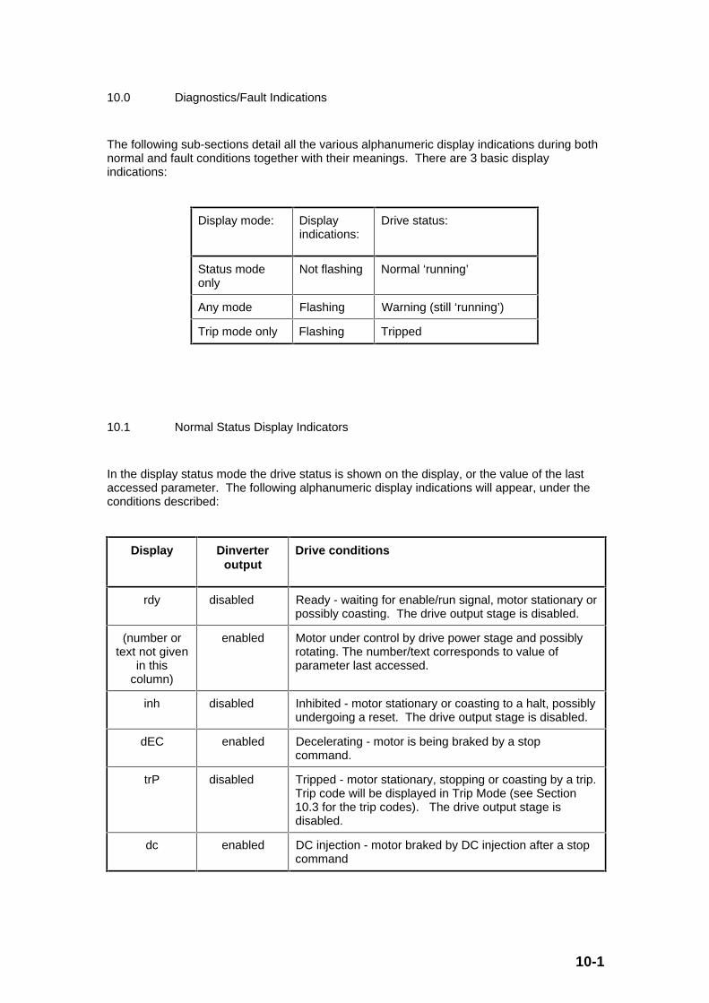
10-1
10.0 Diagnostics/Fault Indications
The following sub-sections detail all the various alphanumeric display indications during bothnormal and fault conditions together with their meanings. There are 3 basic displayindications:
Display mode: Displayindications:
Drive status:
Status modeonly
Not flashing Normal ‘running’
Any mode Flashing Warning (still ‘running’)
Trip mode only Flashing Tripped
10.1 Normal Status Display Indicators
In the display status mode the drive status is shown on the display, or the value of the lastaccessed parameter. The following alphanumeric display indications will appear, under theconditions described:
Display Dinverteroutput
Drive conditions
rdy disabled Ready - waiting for enable/run signal, motor stationary orpossibly coasting. The drive output stage is disabled.
(number ortext not given
in thiscolumn)
enabled Motor under control by drive power stage and possiblyrotating. The number/text corresponds to value ofparameter last accessed.
inh disabled Inhibited - motor stationary or coasting to a halt, possiblyundergoing a reset. The drive output stage is disabled.
dEC enabled Decelerating - motor is being braked by a stopcommand.
trP disabled Tripped - motor stationary, stopping or coasting by a trip.Trip code will be displayed in Trip Mode (see Section10.3 for the trip codes). The drive output stage isdisabled.
dc enabled DC injection - motor braked by DC injection after a stopcommand

10-2
10.2 Warning Display Indicators
If a critical condition is reached, the drive will remain enabled, but the display shows aflashing warning in all of the display modes. The warning condition will be indicated on thedisplay by alternating between the warning and the normal display number/text. Thiscondition will eventually lead to a trip if no corrective measures are taken.
The following alphanumeric warnings will appear in the display, under the conditionsdescribed:
Display Drive warning conditions
OUL Overload - Motor overload, approaching Ixt trip (‘It’), unless loadreduced.
The output current of the drive is higher than the rated motorcurrent and the overload accumulator value has reached 75%, i.e.[#4.20] > 105% and [#4.19] > 75%.
Motor overload alarm [#A.17] = 1.
hot Hot - Heatsink approaching overtemperature trip (‘Oh2’), unlessoutput current reduced, ambient reduced or switching frequencyreduced.
The heatsink has exceeded a temperature of 95°C, i.e. [#7.04] >95oC.
Heatsink temperature alarm [#A.18] = 1.
10.3 Trip Display Indicators
In the event of a trip occurring, the drive output will be immediately disabled and the motorwill coast to a standstill. However, if [#A.37] = 1 (stop drive on non-important trips), a non-important trip will cause the drive to stop first before disabling the drive and then tripping.Once tripped the display will show a flashing trip indicating the cause of the trip. (The serialinterface can also be used to read the trip through the trip log parameters #A.20 to #A.29).
Please note that the 4 trips ‘Er1’, ‘Er2’, ‘Er3’ and ‘Er4’ can only be reset by powering off thedrive, whereas all other trips can be reset via the Drive reset bit #A.33.

10-3
The following trips are possible:
Display
(and alsothe last tripparameters
#A.20 to#A.29)
Valueread via
serialcomms
for #A.20to #A.29
Drive trip conditions, reasons, and help
UU 1 DC link undervoltage
Possible reason: Normal AC supply switched off or supplyvoltage low.
OU 2 DC link overvoltage
Possible reason: Braking torque too high during deceleration.
Help: Use braking resistor, extend deceleration rate.
OI 3 Instantaneous overcurrent (at inverter or brake)
Possible reasons: Acceleration or braking ramp too short,P-term of the current controller (#4.13) too small, short circuit atoutput or brake (at the drive output or motor), faulty motorcable.
Help: Extend ramps, optimise current controller,check drive output, motor cable, motor terminal block, brakeresistor and cabling.
PS 4 Power supply
Possible reasons: Dirt shorting internal drive circuits, faulty unit.
Help: Switch AC supply on and off. If trip persists,consult supplier.
Et 5 External trip ([#A.32] = 1 momentarily)
Possible reasons: Fault in external fault chain, terminal B5open (in default settings)
Help: Check external fault chain, check terminal B5
O.SP 6 Overspeed
Possible reasons: Speed/frequency too high duringregeneration and in current limit.
Help: Remove/reduce overhauling load. Increase thecurrent limit (#4.07) if possible or use a drive with a largercurrent rating.
It 7 Motor Ixt overload
Possible reasons: Motor overloaded.
Help: Reduce load or use larger drive (andmotor) rating.
cL 8 Current loop loss when in 4 to 20 or 2 to 4 mA analogue inputmodes
Possible reasons: Input current less than 3mA when in 4 to20mA or 20 to 4mA modes.
Help: Check parameter setting (#7.11), check currentloops.

10-4
Oh2 9 Heatsink overtemperature
Possible reasons: Overloaded drive, ambient temperature toohigh
Help: Check ambient temperature, use enclosurecooling if necessary; reduce PWM switching frequency ([#0.41]or [#5.18]), use larger drive rating.
EEF 10 EEPROM fault
Possible reasons: Possible parameter loss or corruption causedby severe electrical noise.
Help: Load default values (via parameter 0(i.e.#x.00), see section 5.2.3), then enter application values, storenew parameters, power off and power back on. If EEF trip stillpresent consult supplier.
th 11 Motor thermistor overtemperature ([#A.16] = 1 momentarily)
Possible reasons: Overloaded motor, faulty PTC motorthermistors or wire, PTC thermistor input open at drive terminals
Help: Check PTC motor thermistor input at driveterminal block, check PTC motor thermistors and wire for break,reduce load.
Er1 12 Load current offset too great at power up (should be 0)
Possible reasons: Faulty drive, or severe electrical noise atpower up.
Help: Power off and power back on again. If Er1trip is still present consult supplier.
Er2 13 Microprocessor oscillator faulty
Possible reasons: Faulty drive.
Help: Power off and power back on again. If Er2trip is still present consult supplier.
Er3 14 Microprocessor software not functioning correctly
Possible reasons: Faulty drive, or severe electrical noise atpower up..
Help: Power off and power back on again. If Er3trip is still present consult supplier.
Er4 15 Keypad button depressed at power up
Possible reasons: One of keypad buttons stuck down.
Help: Release stuck button. Power off andpower back on again. If Er4 trip is still present consult supplier.
t16
to
t99
16
to
99
User trips where the number is the trip number ([#A.38] = tripnumber momentarily)
__________

11-1
11.0 Serial Communications
11.1 Introduction
A serial communications link enables one or more drives to be used in systems controlled bya host unit such as a PLC (Programmable Logic Controller) or computer. Thecommunications link for the drive uses the EIA RS485 standard for the hardware interface.
The Dinverter drive has a standard 2-wire RS485 half-duplex interface that enables all driveset-up, operation and monitoring to be accomplished if required. Therefore, it is possible tocontrol the drive entirely by the RS485 interface without the need for other control cabling.
The host controller can operate up to thirty-two EIA RS485 devices with the use of one linebuffer. Further buffers will increase this number if necessary. Each transmitter/receiverwithin a drive (with the internal termination and external pull-up and pull-down resistorsdisconnected) loads the RS485 lines by 1 unit load. This means that up to 32 drives can beconnected in a single group to one line buffer. However, with the serial addresses available,it is convenient to only have up to 9 drives in a single group.
When additional line buffers are used, up to 81 drives can be operated by the host controller.In this case the drives are organised in a maximum of 9 groups of 9 drives each. Aparticular drive or group of drives can be given commands without affecting other drives orgroups of drives respectively.
The serial communications port of the drive is situated at terminals C4 and C5. The EIARS485 2-wire port is isolated from the power stage but not isolated from the other controlterminals. The EIA RS422 hardware interface is also supported.
Note:-
The EIA RS232 hardware interface cannot be used with a 2-wire EIA RS485 interface.Therefore a suitable adapter for connection to a computer RS232 interface port is essential.This adapter must have the hardware and software support to tri-state (i.e. disable) thetransmit buffer following message transmission. Otherwise the Dinverter RS485 transmitterwill not be successful in transmitting a reply as the host transmitter will cause contention ofthe 2-wire interface.

11-2
11.2 Initial Electrical and Mechanical Set-Up
Prior to powering the drive up for the first time, ensure that Sections 4 & 5 of this manualhave been studied and the necessary recommended actions have been taken. For initialoperation using serial communications, it is assumed that the relevant connections are asshown in Fig 11.1 and 11.2.

11-3
0V common
RS485 input
Run forward
Run reverse
Drive enable
External trip
Analog speed reference
Status relay contacts (250VAC, 2A N/O) (optional connection)
Optional braking resistor ≥100Ω
Optional RFI filter
AC supplyFuses and isolator
Analog frequency output signal
Digital inputs
C4/C5 terminating resistor (100Ω) across C4~C5 (0 ~ 20mA) RS485 inputs
Brake
0V common
+10V, 5mA maximum
0V common
Gland X: 3 x 2.5mm (14AWG)
Gland Y: 6 x 1.0mm (18AWG)
Gland Z: 10 x 0.5mm (20AWG)
2
2
2
Optional
2.2kΩ ±10%
System controller (RS485 transceiver)
Termination resistor fitted
Termination resistor removed
First or intermediate Drive on the serial link
Last Drive on the serial link
Connect an external link if no internal connection exists in the transceiver between 0V and ground
Isolation unit
System controller (RS485 transceiver)
Connect an external link if no internal connection exists between isolated 0V and ground
Transceiver and isolation unit (if required)
Fig. 11.1 Electrical connections for initial serial communications operation

11-4
Serial communications requirements
Warning
The RS485 serial communications connections in the Driveare not isolated from the other control circuits and areseparated from the live parts by basic insulation; if theserial communications circuit is to be accessible topersonnel, an isolation unit must be used. When multipleRS485 networks are to be used, each network will requireits own isolation unit.
If more than one Drive is to be connected to a serial link, make connections as shown inFigure 11.1. If only one Drive is to be connected, make the connections shown for the lastDrive.
1 A 100Ω termination resistor must be fitted in the last (or only) Drive on the serial link. Use wire-cutters to remove the termination resistor from all Drives except the last Driveon the serial link.
2 Connect two 2.2kΩ ±10% resistors as shown in Figure 4–11 to the last (or only) Drive, onthe serial link. Adding these resistors improves noise immunity.
3 The serial communications cable must be shielded. The shield(s) must be connected asshown in Figure 4–11.
In particular:
• Check that the wiring is correct,
• Check that the motor installation is correct and safe,
• Check that the motor shaft is not exposed,
• Check that the signal connections B2 and B3 are not connected to 0V Common (i.e. theswitches/contacts are open), and, B4 and B5 are connected to 0V Common (i.e. theswitches/contacts are closed). This ensures that the motor will not turn when AC power isapplied to the drive.
• Check that the Set Speed Potentiometer (connected to A1, A2, and A3) is set to minimum(wiper is effectively connected to 0V Common wiper).
Notes
• A data communications cable should not run parallel to any power cables, especially onesthat connect drives to motors. If parallel runs are unavoidable, ensure a minimumspacing of 300mm (12 in.) between the communications cable and the power cable.
• Cables crossing one another at right-angles are unlikely to give trouble. The maximumcable run length for a EIA RS485 link is 1,200 metres (4,000 feet).
• Care must be taken to ensure that other drives in the system do not have the terminationresistor fitted. Excessive signal loss will occur if resistors are connected on drives otherthan the last one in the group.
Before switching on the power to the drive, it is important to understand the drive operatingcontrols and their operation. If in doubt, DO NOT ADJUST this drive. Damage may occur,or lives may be put at risk. Please read the following sections carefully.
11-5
With the drive wired up as described above, apply power to the input of the drive. The driveshould power up with ‘rdy’ on the display.
With the drive parameters set to default, the terminals C4 and C5 are ready for RS485communication. The drive will have a serial address of 1.1, (group 1, unit 1), at baud rate of4800, and a protocol set by the ANSI standard as defined in Section 11.4 below.
If more than one drive is connected to the host computer, please adjust the serial address ofeach drive to ensure that each drive has a unique address.
Therefore with the drive in the above condition, all commissioning and operation if need becan be done using the RS485 communication link.
11.3 Relevant Parameters
This section gives a full explanation of all the relevant parameters affecting serialcommunications.
#7.11 Analogue input 2 (C4/C5) mode selector
Parameter type: RW, U, T, P
Adjustment range: ANS (0), 0.20 (1), 20.0 (2), 4.20 (3), 20.4 (4), or th (5)
Units: -
Default value: ANS (0)
Analogue input 2 (C4/C5) can be configured for different input signal types (includingserial communications). The setting of this parameter configures the terminals forthe required mode of operation as follows:
#7.11 Setting
(Display)
Setting via
Serial
comms
Description
ANS 0 RS485 ANSI serial comms port active
0.20 1 Current input 0 to 20mA (20mA full scale)
20.0 2 Current input 20 to 0mA (0mA full scale)
4.20 3 Current input 4 to 20mA (20mA full scale)
11-6
20.4 4 Current input 20 to 4mA (4mA full scale)
th 5 Motor thermistor input, see Fig. 9.17 in Section
9.8.2 for further details.
For a complete description of this parameter see the parameter description for #7.11in Section 9.8.2.
#b.23 Serial interface address
Parameter type: RW, U, P
Adjustment range: 0.0 to 9.9
Units: grp.unit (i.e. [group number].[unit number])
Default value: 1.1
Used when terminals C4/C5 are configured in default (i.e. [#7.11] = ANS (0)Analogue input 2 mode selector) to enable the serial interface. Parameter #b.23defines the serial address of the drive. The address has the following format: [drivegroup. drive unit]. There are 9 addressable groups for each of 9 possible drive units.If address [0.0] is used, all drives are addressed simultaneously. If [x.0] is used,where x is any number from 1 to 9, all drives in group x are addressed.
Note that for this drive, the only baud rate available is 4800.
#b.26 Serial transmit delay time
Parameter type: RW, U
Adjustment range: 0 to 250
Units: ms
Default value: 20 (milliseconds)
The serial transmit delay time defines the minimum time before the drive will enableits RS485 transmit buffer and transmit data in response to a message from the host.(Prior to this time the Dinverter RS485 transmit buffer is disabled to enable the hostto transmit a message to the drive receive buffer.) This delay provides the hostsoftware with sufficient time to disable its own transmit buffer after transmitting datato the drive. If the host does not disable the transmit buffer within the delayprovided, the message transmitted from the drive to the host will be lost because ofthe contention with both the host and drive transmit buffers enabled.
11-7
Note also that the drive holds its transmit buffers enabled for up to 4 millisecondsafter it has transmitted the last character of the response. Therefore, the host mustnot start transmitting a new message until this 4ms period has elapsed.
These delays are essential for successful operation of the 2-wire half duplex protocolwhere the transmit and receive data is sent via the same differential pair of wires.
11.4 ANSI Protocol Description
Data is transmitted at a fixed speed or baud rate in the form of a character. A character iscomprised of seven bits, and the baud rate represents the data transmission rate inbits/second.
In order for a data receiver to recognise valid data, a frame is placed around each character. This frame contains a start bit, a stop bit, and a parity bit. Without this frame, the receiverwould be unable to synchronise itself with the transmitted data, as the data is asynchronous.
A frame is shown here:
ASCII 7-bit character (Low ASCII set)
Least significant Hexadecimal digit Most significantHexadecimal digit (3 bitsonly)
Startbit
Seven data bits EvenParitybit
Stopbit
0 bit 0(lsb)
bit 1 bit 2 bit 3 bit 4 bit 5 bit 6(msb)
(0 or1)
1
1st bit 2nd bit 3rd bit 4th bit 5th bit 6th bit 7th bit 8th bit 9th bit 10thbit
The frame above consists of 10 bits:
1 start bit, followed by
7 data bits (starting with the least significant bit (i.e. lsb - bit 0) and ending with
the most significant bit (i.e. msb - bit 6), followed by
11-8
1 even parity bit, followed by
1 stop bit
The parity bit is used by the data receiver to check the integrity of the 7 data bits it hasreceived.
The 7 data bits are called a character and comprise the low ASCII set. The ASCII characterset comprises 128 characters decimally numbered from 0 to 127. The first 32 (0 to 31)characters in the ASCII set (hexadecimal 00H to 01FH) are used to represent special controlcodes. Each control code has a particular meaning (e.g. ASCII character 02 H is called ‘STX’the ‘start of text’).
A message consists of a group of frames or characters. These characters consist of thefollowing types which are used to construct the different types of messages:
Control characters
Address characters
Parameter characters
Data characters
Block Checksum character
These character types are described below.
Control characters
Commands and requests are sent to the drive in the form of a set of characters, includingcontrol characters as a message packet. Each message is started with a special controlcharacter, and may contain further control characters. A list of all the relevant controlcharacters in the ANSI protocol used when sending a message, and receiving is as follows:
Character Meaning ASCII code(2-digit
Hexadecimal)
Control Characteron Computer
Keyboard
EOT End of Transmission -
Reset - prepare for new message
04 Control-D
ENQ Enquiry - interrogating a ‘drive’ 05 Control-E
STX Start of Text (or data) 02 Control-B
ETX End of Text (or data) 03 Control-C
ACK Acknowledge (message accepted) 06 Control-F
NAK Negative acknowledge (message notaccepted)
15 Control-U

11-9
BS Backspace 08 Control-H

11-10
Address characters
Each drive on a ANSI communications serial link must be given a unique identity or addressso that only one target drive will respond to a transmitted message. This serial addresscomprises two parts:
The Group Address which is the first digit of the 2 digit address, and
The Unit Address which is the second digit.
Both the group address and unit address have a range of 1 to 9. A group or unit address of0 is not allowed (i.e. addresses 01, 10, 20, etc. are invalid). The reason for this is that drivescan be grouped together (up to 9 units per group), and a particular message with an addresscontaining 0 can be sent to all units of the particular group. To address a particular group,the unit address of zero (0) is used, for example, to address all units of group 6 the fulladdress is 60.
An additional feature of the ANSI protocol is that a message can be sent to all units of allgroups simultaneously using the address 00. For example, the address 00 can be used tosend a frequency/speed command to all the drives which are mechanically coupled togetherdriving a conveyor. All the drives will then change frequency/speed simultaneously.
Note
It is important to realise that when using group addressing (e.g. addresses 00, 10, 20 etc.),the drives within the group addressed will not acknowledge the message sent. (If severaldrives try to respond at the same time, they would all be transmitting simultaneously which isnot possible when the serial link can only work with one transmitter active at any one time.)
For security, the format of the transmitted address requires that each digit of the two-digitaddress is repeated, i.e. the address of drive 23 is sent as four characters, e.g. ‘2 2 3 3’.
The serial address immediately follows after the first control character of the message(usually ‘EOT’).
Parameter characters
For transmission, all parameters are identified by four digits representing the menu and theparameter number, but without the decimal point. Examples:
To send a message to menu 4, parameter 16, (i.e. parameter #4.16), send ‘0416’(the leading zero must be included)
To send to menu E, parameter 3, (i.e. parameter #E.03) send ‘1503’ where 15 is thedecimal equivalent of E (in hexadecimal).
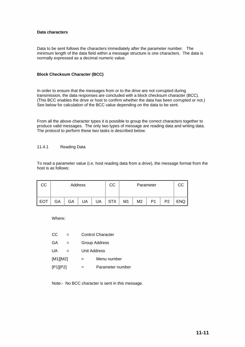
11-11
Data characters
Data to be sent follows the characters immediately after the parameter number. Theminimum length of the data field within a message structure is one characters. The data isnormally expressed as a decimal numeric value.
Block Checksum Character (BCC)
In order to ensure that the messages from or to the drive are not corrupted duringtransmission, the data responses are concluded with a block checksum character (BCC).(This BCC enables the drive or host to confirm whether the data has been corrupted or not.)See below for calculation of the BCC value depending on the data to be sent.
From all the above character types it is possible to group the correct characters together toproduce valid messages. The only two types of message are reading data and writing data.The protocol to perform these two tasks is described below.
11.4.1 Reading Data
To read a parameter value (i.e. host reading data from a drive), the message format from thehost is as follows:
CC Address CC Parameter CC
EOT GA GA UA UA STX M1 M2 P1 P2 ENQ
Where:
CC = Control Character
GA = Group Address
UA = Unit Address
[M1][M2] = Menu number
[P1][P2] = Parameter number
Note:- No BCC character is sent in this message.
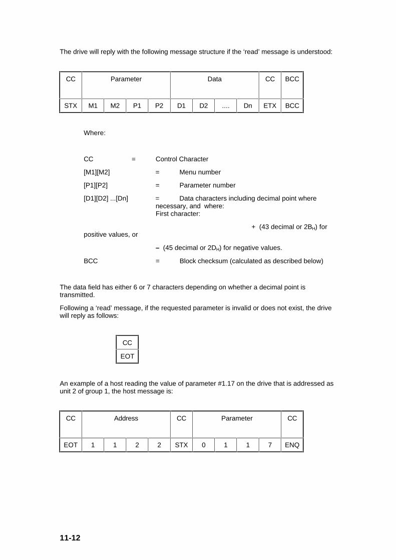
11-12
The drive will reply with the following message structure if the ‘read’ message is understood:
CC Parameter Data CC BCC
STX M1 M2 P1 P2 D1 D2 .... Dn ETX BCC
Where:
CC = Control Character
[M1][M2] = Menu number
[P1][P2] = Parameter number
[D1][D2] ...[Dn] = Data characters including decimal point where necessary, and where:First character:
+ (43 decimal or 2BH) forpositive values, or
– (45 decimal or 2DH) for negative values.
BCC = Block checksum (calculated as described below)
The data field has either 6 or 7 characters depending on whether a decimal point istransmitted.
Following a ‘read’ message, if the requested parameter is invalid or does not exist, the drivewill reply as follows:
CC
EOT
An example of a host reading the value of parameter #1.17 on the drive that is addressed asunit 2 of group 1, the host message is:
CC Address CC Parameter CC
EOT 1 1 2 2 STX 0 1 1 7 ENQ

11-13
The drive replies with, where [#1.17] = -47.6Hz:
CC Parameter Data CC BCC
STX 0 1 1 7 - 0 0 4 7 . 6 ETX 2
The BCC in this example is calculated by the drive as follows:
Calculating the block checksum (BCC)
The block checksum is calculated by applying an exclusive ‘or’ function (XOR) to all of thecharacters of a message after the ‘STX’ control character.
XOR truth table
A B Out
0 0 0
0 1 1
1 0 1
1 1 0
For the ‘read’ response example above:
The first character of the BCC calculation is 0 (0011 0000 in binary), the value ofwhich is taken as a starting or result value. The next character is 1 (0011 0001 inbinary), which now has the exclusive ‘or’ (XOR) operator act upon it. With theprevious result value, a new result occurs of (0000 0001) in binary.
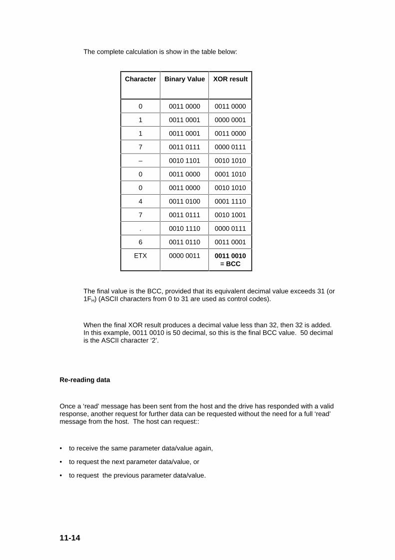
11-14
The complete calculation is show in the table below:
Character Binary Value XOR result
0 0011 0000 0011 0000
1 0011 0001 0000 0001
1 0011 0001 0011 0000
7 0011 0111 0000 0111
– 0010 1101 0010 1010
0 0011 0000 0001 1010
0 0011 0000 0010 1010
4 0011 0100 0001 1110
7 0011 0111 0010 1001
. 0010 1110 0000 0111
6 0011 0110 0011 0001
ETX 0000 0011 0011 0010= BCC
The final value is the BCC, provided that its equivalent decimal value exceeds 31 (or1FH) (ASCII characters from 0 to 31 are used as control codes).
When the final XOR result produces a decimal value less than 32, then 32 is added.In this example, 0011 0010 is 50 decimal, so this is the final BCC value. 50 decimalis the ASCII character ‘2’.
Re-reading data
Once a ‘read’ message has been sent from the host and the drive has responded with a validresponse, another request for further data can be requested without the need for a full ‘read’message from the host. The host can request::
• to receive the same parameter data/value again,
• to request the next parameter data/value, or
• to request the previous parameter data/value.
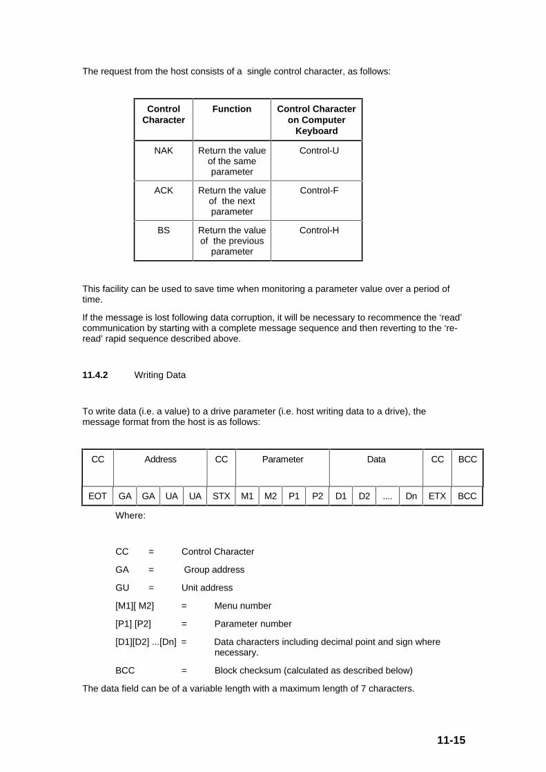
11-15
The request from the host consists of a single control character, as follows:
ControlCharacter
Function Control Characteron Computer
Keyboard
NAK Return the valueof the sameparameter
Control-U
ACK Return the valueof the nextparameter
Control-F
BS Return the valueof the previous
parameter
Control-H
This facility can be used to save time when monitoring a parameter value over a period oftime.
If the message is lost following data corruption, it will be necessary to recommence the ‘read’communication by starting with a complete message sequence and then reverting to the ‘re-read’ rapid sequence described above.
11.4.2 Writing Data
To write data (i.e. a value) to a drive parameter (i.e. host writing data to a drive), themessage format from the host is as follows:
CC Address CC Parameter Data CC BCC
EOT GA GA UA UA STX M1 M2 P1 P2 D1 D2 .... Dn ETX BCC
Where:
CC = Control Character
GA = Group address
GU = Unit address
[M1][ M2] = Menu number
[P1] [P2] = Parameter number
[D1][D2] ...[Dn] = Data characters including decimal point and sign where necessary.
BCC = Block checksum (calculated as described below)
The data field can be of a variable length with a maximum length of 7 characters.
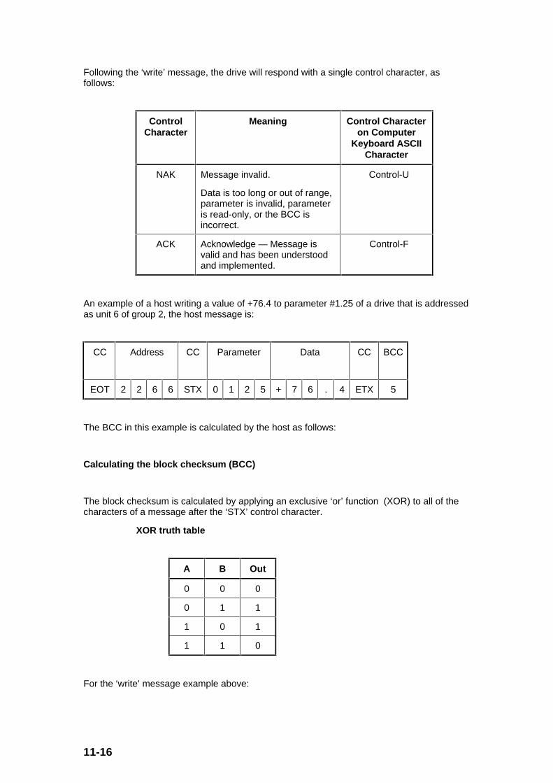
11-16
Following the ‘write’ message, the drive will respond with a single control character, asfollows:
ControlCharacter
Meaning Control Characteron Computer
Keyboard ASCIICharacter
NAK Message invalid.
Data is too long or out of range,parameter is invalid, parameteris read-only, or the BCC isincorrect.
Control-U
ACK Acknowledge — Message isvalid and has been understoodand implemented.
Control-F
An example of a host writing a value of +76.4 to parameter #1.25 of a drive that is addressedas unit 6 of group 2, the host message is:
CC Address CC Parameter Data CC BCC
EOT 2 2 6 6 STX 0 1 2 5 + 7 6 . 4 ETX 5
The BCC in this example is calculated by the host as follows:
Calculating the block checksum (BCC)
The block checksum is calculated by applying an exclusive ‘or’ function (XOR) to all of thecharacters of a message after the ‘STX’ control character.
XOR truth table
A B Out
0 0 0
0 1 1
1 0 1
1 1 0
For the ‘write’ message example above:
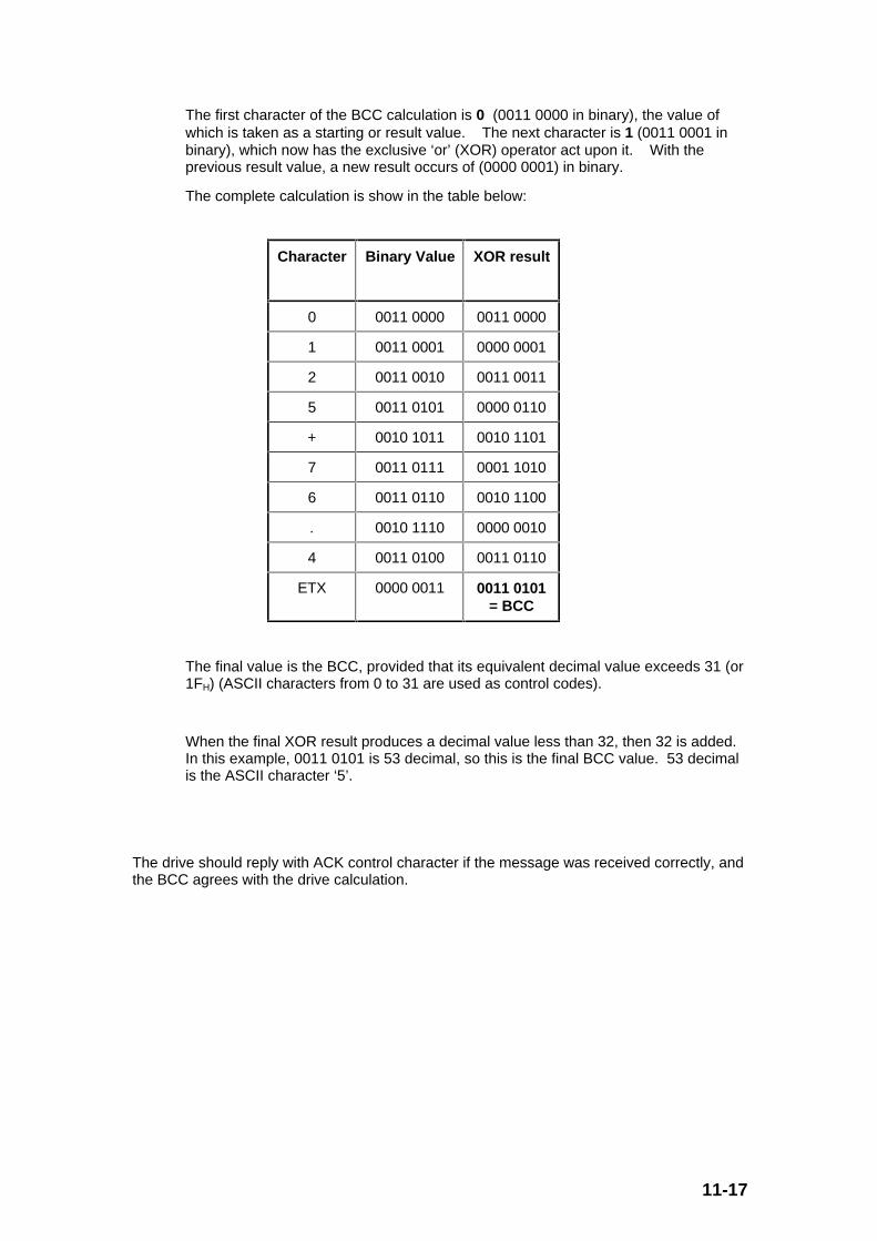
11-17
The first character of the BCC calculation is 0 (0011 0000 in binary), the value ofwhich is taken as a starting or result value. The next character is 1 (0011 0001 inbinary), which now has the exclusive ‘or’ (XOR) operator act upon it. With theprevious result value, a new result occurs of (0000 0001) in binary.
The complete calculation is show in the table below:
Character Binary Value XOR result
0 0011 0000 0011 0000
1 0011 0001 0000 0001
2 0011 0010 0011 0011
5 0011 0101 0000 0110
+ 0010 1011 0010 1101
7 0011 0111 0001 1010
6 0011 0110 0010 1100
. 0010 1110 0000 0010
4 0011 0100 0011 0110
ETX 0000 0011 0011 0101= BCC
The final value is the BCC, provided that its equivalent decimal value exceeds 31 (or1FH) (ASCII characters from 0 to 31 are used as control codes).
When the final XOR result produces a decimal value less than 32, then 32 is added.In this example, 0011 0101 is 53 decimal, so this is the final BCC value. 53 decimalis the ASCII character ‘5’.
The drive should reply with ACK control character if the message was received correctly, andthe BCC agrees with the drive calculation.

11-18
Re-writing data
Once a complete ‘write’ message has been sent to a drive, and the drive has responded witheither a ‘ACK’ or ‘NAK’ character, subsequent ‘write’ messages to that particular drive canuse a re-write message structure. The address does not need to be re-transmitted. The ‘re-write’ message structure is as follows:
CC Parameter Data CC BCC
STX M1 M2 P1 P2 D1 D2 .... Dn ETX BCC
When a different drive needs to be addressed, or an ACK or NAK response is not receivedfrom the current drive addressed, the ‘re-write’ facility can no longer be used. Theparticular drive can only be addressed by using the full ‘write’ message with the correctaddress, etc.
_________