Technical Purchasing Conditions · 2016-12-09 · DIN EN ISO 13920 Welding - General tolerances for...
24
www.sartorius.com Technical Purchasing Conditions Quality Requirements TEB-EN Revision 01/2015
Transcript of Technical Purchasing Conditions · 2016-12-09 · DIN EN ISO 13920 Welding - General tolerances for...

www.sartorius.com
Technical Purchasing Conditions Quality Requirements
TEB-EN
Revision 01/2015
Page 2 of 24
Introduction
Outstanding Quality as a Commitment to
Providing Maximum Customer Value These technical purchasing conditions (TPCs) describe the general quality requirements placed by Sartorius Stedim Systems GmbH, called “SSS” in the following, on products and processes of its suppliers and subcontractors.
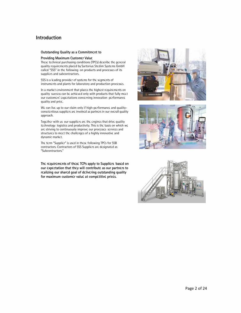
SSS is a leading provider of systems for the segments of instruments and plants for laboratory and production processes.
In a market environment that places the highest requirements on quality, success can be achieved only with products that fully meet our customers’ expectations concerning innovation, performance, quality and price.
We can live up to our claim only if high-performance and quality-conscientious suppliers are involved as partners in our overall quality approach.
Together with us, our suppliers are the engines that drive quality, technology, logistics and productivity. This is the basis on which we are striving to continuously improve our processes, services and structures to meet the challenges of a highly innovative and dynamic market.
The term “Supplier” is used in these following TPCs for SSB contractors. Contractors of SSS Suppliers are designated as “Subcontractors.”
The requirements of these TCPs apply to Suppliers, based on our expectation that they will contribute as our partners to realizing our shared goal of delivering outstanding quality for maximum customer value at competitive prices.
Technical Purchasing Conditions
Page 3 of 24
Inhalt
Introduction .................................................................................................................................................................................... 2 1.0 General Requirements ...................................................................................................................................................... 5 2.0 General Mechanical Requirements ................................................................................................................................. 5
2.1 Tolerances, Standards and Specifications .............................................................................................................. 5 2.1.1 General Tolerances .................................................................................................................................................... 5 2.1.2 Fits .................................................................................................................................................................................. 6 2.1.3 Drilled Holes / Counter-bored Holes .................................................................................................................... 6 2.1.4 Threads .......................................................................................................................................................................... 6 2.1.5 Quality of Edges ......................................................................................................................................................... 7 2.1.6 Quality of Bends ......................................................................................................................................................... 8 2.1.7 Adhesive Specifications ......................................................................................................................................... 8 2.1.8 Surfaces ....................................................................................................................................................................... 8
2.1.8.1 Pickling and Passivation ................................................................................................................................... 8 2.1.8.2 Electropolished Stainless Steel Surfaces ...................................................................................................... 9 2.1.8.3 Ground / Brushed Decorative Surface Finishes ........................................................................................... 9 2.1.8.4 Paint-coated / Powder-coated Surfaces .................................................................................................... 10 2.1.8.5 Paint- or Powder-free Surfaces ................................................................................................................... 10 2.1.8.6 Other Surfaces ................................................................................................................................................... 10
2.2 Welding ......................................................................................................................................................................... 11 2.2.1 Compliance with Additional Requirements on Welded Joints ................................................................... 12 2.2.2 ISO 4063 Welding Process ..................................................................................................................................... 12 2.2.3 Qualification of Welders ........................................................................................................................................ 12 2.2.4 Preparation for Welding ........................................................................................................................................ 13 2.2.5 DIN EN ISO 14175 Welding Gas........................................................................................................................... 13 2.2.6 Tungsten Electrodes ................................................................................................................................................ 13 2.2.7 DIN EN ISO 14343 Welding Filler Metals .......................................................................................................... 13 2.2.8 Requirements on Welded Joints for Product-contacted Areas ................................................................... 14 2.3 Manufacture and Assembly ...................................................................................................................................... 15 2.3.1 Requirements on the Manufacturing and Assembly Facilities ................................................................... 15 2.3.2 Machining of Semi-finished Products ............................................................................................................... 15 2.3.3 Thermal Cutting of Semi-finished Products .................................................................................................... 15 2.3.4 Grinding, Bead Blasting and Polishing .............................................................................................................. 15 2.3.5 Sealing Threads ......................................................................................................................................................... 16 2.3.6 Assembly of Subassemblies ................................................................................................................................... 16 2.3.7 Compression Fittings ................................................................................................................................................ 16 2.3.8 Ball Bearings and Axial Face Seals ...................................................................................................................... 16 2.3.9 Tube Clamps and Tubing ........................................................................................................................................ 16 2.3.10 Standardized Parts in Product-contacted Areas .......................................................................................... 17 2.4 Materials ........................................................................................................................................................................ 17 2.4.1 Labeling and Traceability ....................................................................................................................................... 17 2.4.2 Requirements for Laser Labeling ......................................................................................................................... 18 2.4.3 Manufacturer’s Certificate .................................................................................................................................... 18 2.4.4 SSS Article Number ................................................................................................................................................. 18 2.4.5 Supplier ID Code ........................................................................................................................................................ 18

Technical Purchasing Conditions
Page 4 of 24
2.4.6 Serial Number ........................................................................................................................................................... 19 2.4.7 Lot Number ................................................................................................................................................................ 19 2.4.8 Sartorius Logo ........................................................................................................................................................... 19 2.4.9 Labeling Matrix......................................................................................................................................................... 20 2.5 Documentation Matrix .............................................................................................................................................. 21 2.5.1 Documentation Matrix ........................................................................................................................................... 21 2.5.2 Document Filing / Electronic Transmission ...................................................................................................... 21 2.5.3 Documentation on Welded Joints / List of Welded Joints ........................................................................... 21 2.5.4 Pressure Equipment ................................................................................................................................................. 21 2.6 Specification on Gasket Materials – Standardized Parts ................................................................................. 22 2.6.1 Elastomers .................................................................................................................................................................. 22 2.6.2 O-rings ........................................................................................................................................................................ 22 2.6.3 Clamp Connections / Clamp Gaskets .................................................................................................................. 22 2.6.4 Flange Gaskets .......................................................................................................................................................... 22 2.6.5 Flat Gaskets ................................................................................................................................................................ 23 2.6.6 Membranes ................................................................................................................................................................. 23
3.0 Packaging and Transportation .................................................................................................................................... 23 Postscript: ...................................................................................................................................................................................... 24
Page 5 of 24
1.0 General Requirements
These Technical Purchase Conditions, called TPC in the following, shall generally apply to all products supplied to Sartorius Stedim Systems GmbH, subsequently designated as SSS. These TPCs are to be considered the minimum requirements, which may be supplemented by product- and process-specific definitions as required.
Products are all subassemblies, individual parts, systems and services delivered by a Supplier. The following approaches and definitions described are standards at SSS.
2.0 General Mechanical Requirements The requirements defined in this chapter and standards listed shall apply, unless otherwise specified in the particular product documents, to all mechanical subassemblies and individual parts.
2.1 Tolerances, Standards and Specifications The tolerances, standards and specification requirements listed here shall be used in their particular valid versions as amended.
2.1.1 General Tolerances Standard to be applied:
DIN EN ISO 1101 Geometrical product specifications (GPS) - Geometrical tolerancing - Tolerances of form, orientation, location and run-out
DIN EN ISO 1302 Geometrical product specifications (GPS) - Indication of surface texture in technical product documentation
DIN EN ISO 13920 Welding - General tolerances for welded constructions - Dimensions for lengths and angles; shape and position
DIN 28005 Tolerances for vessels - Part 1: Vessels of metallic materials
DIN ISO 2768 General tolerances
The general tolerances refer to fully machined parts, including their surfaces, according to DIN ISO 2768, parts 1 and 2.
For SSS, tolerance classes m (T1) and H (T2) are defined.
Page 6 of 24
2.1.2 Fits Applicable standards:
DIN ISO 286 Geometrical product specification (GPS) - ISO code system for tolerances on linear sizes - Part 1: Basis of tolerances, deviations and fits
This standard defines fit systems and the principles of "basic hole" and "basic shaft," as well as the terms of basic deviations, fundamental tolerances, tolerance zone, tolerance degree and tolerance class.
2.1.3 Drilled Holes / Counter-bored Holes Applicable standards:
DIN 74 Countersinks for countersunk head screws except countersunk head screws with heads according to DIN EN 27721
DIN ISO 13715 Technical drawings - Edges of undefined shape - Vocabulary and indication on drawings
For blind holes, the specified dimensions for drilling hole depths are considered the minimum dimensions.
The edges that result from the manufacture of drilled and counter-bored holes must be free of burrs as defined by DIN ISO 13715.
For removal of material according to DIN ISO 13715, a deburred dimension of -0.1 mm to -0.3mm is defined, unless otherwise specified on drawings.
The through-holes of the counter-bored holes shall be produced according to DIN EN 20273, “medium (m)” design.
2.1.4 Threads Applicable Standards:
DIN 13-1 Metric ISO thread for general application – Nominal dimensions (M)
ISO 228-1 Pipe threads where pressure-tight joints are not made on the threads - Part 1: Dimensions, tolerances and designation (G)
DIN 2999-1 Pipe threads where pressure tight joints are made on the threads - Part 1: Taper external threads: Pipe threads and fittings (Rp)
Page 7 of 24
DIN 3858 Pipe threads where pressure tight joints are made on threads: Taper external threads (R) American Standard Taper Pipe Thread), non-sealing (NTP)
ISO 1478 Tapping screws thread (ST)
DIN 405-1 to DIN 405-2 General purpose knuckle threads - Part 1: Profiles, nominal sizes; Part 2:
Deviations and tolerances (Rd)
DIN 40430 Steel conduit thread (“Panzergewinde”, abbreviated “PG”)
DIN 76-1 Thread run-outs
DIN 78 Protrusion of end bolts
DIN 7952 Sheet metal anchorage with threads
DIN ISO 261 Metric ISO thread for general application – Overview
Dimensions for thread depths without specific tolerances are to be considered minimum dimensions. Thread run-outs / undercuts shall be designed as for the standard described in DIN 76-1.
In deviation from DIN 76-1, a 90° counter bore is permitted for internal threads, where the diameter of the counter bore shall be 1 to 1.05 times the internal diameter of the thread.
Thread ends shall be produced according to DIN 78. For external threads, a 45° chamfer shall be added, with an incomplete thread in the run-out area up to 2 x P (P= thread lead) being permitted.
Threads, thread intakes, thread run-outs and undercuts for product-contacted areas must be supplied in a condition that is free of burs and without any particles as a result of machining.
2.1.5 Quality of Edges Applicable standards:
DIN ISO 13715 Edges on work pieces
The edges must be produced so that they are free of burrs according to DIN ISO 13715.
The specifications on the drawings shall apply.
If no specifications are indicated, the dimension (see DIN ISO 13715) for machined parts – does not apply to sheet metal [plate] parts or thin-walled parts – shall be – 0.1 mm to 0.3 mm.
For plate or thin-walled parts, it must be ensured that the width of the remaining surface between two deburred edges is not less than the dimension of the removed material. In cases where deburring causes new

Page 8 of 24
hazards of injury, the edges shall be rounded in a suitable manner or the edge quality shall be determined by SSS.
2.1.6 Quality of Bends Applicable standards:
DIN 9003 Aerospace: Bending of plates and strips
The bending zones must be free of cracks and may not be coarse-grained.
2.1.7 Adhesive Specifications If adhesive joints are required, the order documents or drawings must include the corresponding information. If such information is missing, this shall be clarified with SSS.
All adhesive joints shall be produced according to the relevant specifications of the adhesive manufacturer.
The retaining forces indicated in the documents are to be examined and documented by suitable measures in order to prove that process reliability and/or safety will be maintained.
2.1.8 Surfaces Applicable standards:
DIN 5033 Colorimetry – Basic terms
The attributes specified in the drawings refer to the finished parts, including their surface finish and/or coating. Damage, such as scratches, is considered unacceptable at all times. This applies especially to visible parts.
The SSS standard surface has a peak-to-valley height Ra<0.4µm or Ra<0.8µm in product-contacted areas and Ra<1.2 µm in non-product-contacted areas. For the specific quality of surfaces required, please refer to the respective drawings and order specifications.
2.1.8.1 Pickling and Passivation
Pickling is done to remove all contaminants from a stainless steel surface to obtain a metallurgically clean surface (free of heat tint). Only on such a clean surface can a protective oxide film form, called self-passivation.
Page 9 of 24
Passivation means to use suitable chemicals that enable a stainless steel surface to form a protective passive layer.
2.1.8.2 Electropolished Stainless Steel Surfaces Electropolishing, a chemical surface-finishing technique that electrolytically removes metal (e.g., the Poligrat process E 268® or equivalent) from stainless steel surfaces is used to achieve a variety of technical and functional characteristics as well as decorative properties as well as to completely remove all particles.
Defined removal rates must be determined by trial. Average rates of removal are between 10 µm and 40 µm.
To obtain a defined surface roughness (Ra) after electropolishing, pretreatment (involving pre-grinding, lathing and milling) must be carried out accordingly. Flaws, such as pores in welded joints, sink holes and foreign inclusions, can become visible only after electropolishing.
The degree of gloss of the electropolished surfaces must be glossy to high-gloss. SSS may request that the Supplier provide reference samples.
The following is unacceptable:
Scratches on surfaces Burned edges and surfaces Patchy, matte or rough surfaces (orange peel or alligator skin) Shadow caused by incorrect positioning in the electropolishing bath Contact areas in the visible area Deterioration of the surface finish by electropolishing, which is caused by sink holes in
material (poor quality) Subsequent bleeding of pickling and electrolytic residues caused by incomplete rinsing Rates of removal that damage the fit, rendering a workpiece as scrap Residues left by insufficient cleaning before pickling and electropolishing (pipe labeling,
adhesives, etc.) on the finally treated stainless steel surfaces Adhesive labels of any kind on stainless steel surfaces
Sintered filters (e.g., supplied by the manufacturer GKN® or the equivalent) may not be pickled or electropolished as residue-free rinsing cannot be guaranteed.
2.1.8.3 Ground / Brushed Decorative Surface Finishes The direction of grinding and the surface roughness (e.g., grain 240) specified on the drawing must be observed. The entire manufacturing lot must have a consistently ground pattern and depth.
Care must be taken to ensure adequate protection of the ground surfaces in the further manufacturing process, as well as during storage and transportation.
Page 10 of 24
2.1.8.4 Paint-coated / Powder-coated Surfaces The Supplier must ensure that the paints / powders are processed in compliance with the specifications of the paint or powder manufacturers. The parts to be paint-coated must be free of corrosion, scale, gummed oil and other contaminants. The paint coating must be applied evenly over the surfaces and be free of contaminants.
In the case of changes of colors or textures (structures), a sample must be released by SSS. If required, the surfaces must be previously coated with primer that meets SSS’s requirements before the top paint coating is applied.
Details regarding paint and powder manufacturers are specified in the product documents or must be requested, if not provided, by the purchaser.
To prevent color differences, the paints and powders must be purchased from these manufacturers specified.
2.1.8.5 Paint- or Powder-free Surfaces As a rule, machined surfaces, fits and threads must remain uncoated. Exceptions are specifically marked in the drawings as “coated,” “powder-coated” or similar.
Paint residues or residues of masking materials or those subject to wear on parts are not permissible.
2.1.8.6 Other Surfaces These must be according to generally applicable technical specifications.
All finished products must be supplied in a condition free of shavings, chips, dust particles and other residues.
Parts made using metal-cutting manufacturing processes must be free of oil and grease (without coolants and lubricants).
Page 11 of 24
2.2 Welding Applicable standards:
DIN EN 10 204 Metallic products – Types of inspection documents
DIN EN ISO 3834-1 Quality requirements for welding – Fusion welding of metallic materials – Part 1: Guidelines for selection and use
DIN EN ISO 3834-2 Part 2: Comprehensive quality requirements
DIN EN ISO 3834-3 Part 3: Standard quality requirements
DIN EN ISO 3834-4 Part 4: Elementary quality requirements
DIN EN ISO 2553 Welding and allied processes – Symbolic representation on drawings
DIN EN ISO 5817 Arc-welded joints in steel; guidance on quality levels for imperfections
DIN EN ISO 4063 Welding and allied processes – Nomenclature of processes and reference numbers
DIN EN ISO 13920 Welding – General tolerances for welded constructions – Dimensions for lengths and angles – Shape and position
DIN EN ISO 9606-1 Qualification testing of welders – Fusion welding – Part 1: Steels; welders must have the appropriate qualification test certificate
DIN EN ISO 14732 Welding personnel – Qualification testing of welding operators and weld setters of mechanized and automatic welding of metallic materials
DIN EN ISO 14731 Welding coordination – Tasks and responsibilities
Welders must have a certificate in accordance with DIN EN ISO 9606-1. The Supplier must have or must have commissioned a welding coordinator in accordance with DIN EN ISO 14731. The Supplier shall meet the welding requirements set forth in DIN EN ISO 3834

Page 12 of 24
2.2.1 Compliance with Additional Requirements on Welded Joints The Supplier shall meet the following additional requirements:
Gesichtspunkt
Standard
Requirement
Forderung
Additonal requirement Forderung
Comments
Anmerkung Material Stainless steels
1.4301 (AISI 304), 1.4404/1.4435 (316L)
DIN EN 10 204 Works test certificate 3.1
Austenitic Cr-Ni steel
Operational requirements
DIN EN ISO 3834
Part 2 (Comprehensive)
Part 3 (Standard)
Furnish evidence for welder certificates and welding supervisors
Welded joint quality
DIN EN ISO 5817
Classification Group “B”
For product-contacted areas; does not apply to assembly frames (Group “C”)
Flame-cutting quality (laser)
DIN EN ISO 9013
Laser fusion cutting
Validity of tolerances unless otherwise specified
2.2.2 ISO 4063 Welding Process Welded joints on Cr-Ni steel are to be executed using the tungsten inert gas welding (TIG welding) process 141 and 142.
Different processes, such as laser welding, are possible; however, the Supplier must obtain prior permission from SSS for the use of such different processes.
As far as technically feasible, welds are to be executed using orbital welding equipment (mechanical and automatic welding). Manual welding is permissible only in cases where orbital welding cannot be done due to space requirements.
2.2.3 Qualification of Welders If subassemblies are to be executed as pressure equipment according to PED (AD2000 HP3) / ASME / CHINA (SELO), all welders must be qualified according to DIN EN ISO 9606-1 for manual welding and/or according to DIN EN ISO 14732 for automatic/mechanical welding. For all other subassemblies, these prerequisites must be met. The welder test qualification certificates must be available on the Supplier’s premises and presented, if required.
Page 13 of 24
2.2.4 Preparation for Welding The cutting tools used (cutting blades, milling cutters, etc.) may only be employed for machining stainless steels (austenitic Cr-Ni steel). It is not permitted to use abrasive tools for cutting.
Markings shall be made using markers or marking agents that do not contain any sulfur or carbon and chlorine. Wax crayons or grease pencils may not be used.
Before beginning a welding operation, all parts to be welded must be absolutely clean in an area of 50 mm from each side of the welding zone. A suitable cleaning agent, such as acetone, must be used to clean the parts by wiping them down with a lint-free cloth or paper towel.
Preferred cleaning agent: TUNAP® Tunclean 895 liquid cleaner without chlorinated hydrocarbons cleans without leaving any residues; otherwise, use equivalent cleaning agent.
No grease, oil, dust, dirt, paint or other contaminants may remain on piping. Before welding, dust, shavings and chips from grinding must be properly removed from the inside and outside of conduits.
2.2.5 DIN EN ISO 14175 Welding Gas To prevent interior oxidation during welding, sufficient shielding gas must be used. The Supplier shall ensure that any oxygen has been displaced before welding. Forming is to be carried out using the necessary minimum preliminary gas pressure and with the corresponding pre-flow and post-surge time.
2.2.6 Tungsten Electrodes As a rule, tungsten electrodes with oxide additives must be used. If the lot of the electrodes changes, the welding parameters must be corrected.
2.2.7 DIN EN ISO 14343 Welding Filler Metals Butt welds up to t=3mm should not be welded using welding filler metals.
A welding filler metal must be suitable for the task and approved. It may not have an adverse effect on the basic material of a part.
If welding filler metals are required, for example, during manual welding, these must be verified by a DIN EN 10204 - 3.1 material certificate. Identification of such filler metals must be possible at all times.
Page 14 of 24
Permissible welding filler metals:
Parent metal no. Filler metal no. 1.4301 (AISI 304) 1.4430 (AISI 316L)
1.4404 (~AISI 316 L) 1.4430 / 1.4519 (AISI 316L/AISI 904 L)
1.4435 1.4430 / 1.4519 (AISI 316L/AISI 904 L)
316L 1.4430 / 1.4519 (AISI 316L/AISI 904 L)
2.2.8 Requirements on Welded Joints for Product-contacted Areas
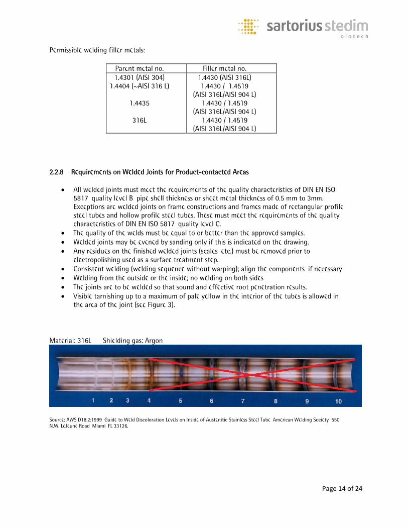
All welded joints must meet the requirements of the quality characteristics of DIN EN ISO 5817, quality level B, pipe shell thickness or sheet metal thickness of 0.5 mm to 3mm. Exceptions are welded joints on frame constructions and frames made of rectangular profile steel tubes and hollow profile steel tubes. These must meet the requirements of the quality characteristics of DIN EN ISO 5817, quality level C.
The quality of the welds must be equal to or better than the approved samples. Welded joints may be evened by sanding only if this is indicated on the drawing. Any residues on the finished welded joints (scales, etc.) must be removed prior to
electropolishing used as a surface treatment step. Consistent welding (welding sequence without warping); align the components, if necessary Welding from the outside or the inside; no welding on both sides The joints are to be welded so that sound and effective root penetration results. Visible tarnishing up to a maximum of pale yellow in the interior of the tubes is allowed in
the area of the joint (see Figure 3).
Material: 316L Shielding gas: Argon
Source: AWS D18.2:1999, Guide to Weld Discoloration Levels on Inside of Austenitic Stainless Steel Tube, American Welding Society, 550 N.W. LeJeune Road, Miami, FL 33126.
Page 15 of 24
2.3 Manufacture and Assembly 2.3.1 Requirements on the Manufacturing and Assembly Facilities It is mandatory to segregate untreated steel (black steel) from stainless steel in all areas.
Semi-finished products and other accessory parts must be properly stored and protected from contamination and damage, both inside and outside, so that these will not be affected in any way on a permanent basis. The material ID number with the melt number must be retained during storage.
Subassemblies shall be assembled on clean, oil- and grease-free work surfaces.
2.3.2 Machining of Semi-finished Products The cutting tools used (cutting blades, milling cutters, etc.) may be employed only for austenitic Cr-Ni steels. Care must be taken to entirely prevent contamination of the parent material with ferrite particles. It is not permitted to use abrasive tools for cutting.
2.3.3 Thermal Cutting of Semi-finished Products
Laser-beam cutting tools used to cut CrNi steel sheets (laser-fusion cutting) may not have any negative effects on the material (corrosion). The quality of the surface roughness and cut edges must conform to the specifications given on the drawing. If a cut begins and ends in one area, no burrs (excess) may remain. Penetration points must lie outside the finished contour.
2.3.4 Grinding, Bead Blasting and Polishing Mechanical grinding, bead blasting and polishing operations are used to achieve the required surface finishes and surface roughness values. The Supplier shall rule out any contamination of the parent material by ferrite particles as a result of using contaminated auxiliary means (e.g., corundum, glass beads, abrasive belts and polishing pins).
At the end of machining, the parts must be cleaned so that no polishing paste residue, dust or other contaminants adhere to them. Such contaminants will have an adverse effect on electropolishing used as a surface treatment process.
The abrasives, beads and polishing or burnishing agents must be free of animal-derived ingredients (ADI- free, free of TSEs / BSEs).
Page 16 of 24
2.3.5 Sealing Threads If the threads of screw connections and fittings have to be sealed so they are leak tight for pressurized media, this shall be done using PTFE thread sealing tape.
Preferred thread sealing tape: CHESTERTON® GoldEnd® PTFE sealing tape (for example, no. 000802), FDA-approved, including oxygen certification or the equivalent. Any PTFE tape protruding from the screw connection must be cleanly cut off.
Screw lock lacquers or sealants may only be used if this is specified on the drawings. See also subheading “Gluing Instructions.” If prior approval has been obtained from SSS, LOCTITE® or comparable products may be used.
2.3.6 Assembly of Subassemblies To prevent so-called cold welding or seizure of threaded stainless steel parts, particularly in the case of matching movable parts, such as threads and conduits with O-rings, these must be slightly lubricated. An FDA-compliant lubricant shall be used for product-contacted areas.
Preferred lubricant: O-Ring grease MOLYKOTE® art. no. 111 FDA-compliant - or the equivalent
2.3.7 Compression Fittings It is mandatory to follow the manufacturer’s instructions (e.g., preparation and starting torque) while assembling compression fittings, such as SERTO®, SCHWER® and SWAGELOK® brand fittings. Where required, special tools and devices shall be used.
2.3.8 Ball Bearings and Axial Face Seals Ball bearings and axial face seals are sensitive components that require the greatest care during their assembly. Therefore, the manufacturer’s instructions must be followed. For assembly of ball bearings, the proper assembly tools with compression devices shall be used; using a hammer to drive ball bearings into the raceways is not permitted whatsoever. The Supplier shall follow the assembly sequence required for achieving the correct results.
2.3.9 Tube Clamps and Tubing Tube clamps, such as OETIKER® ear clamps, must be produced using the clamping pressure and assembly tools specified by the manufacturer.
Page 17 of 24
All tubing used may be cut into the specified lengths only using suitable tube cutters in order to ensure a clean fit.
2.3.10 Standardized Parts in Product-contacted Areas Stainless steel parts used in product-contacted areas (set screws, locking rings, screws, washers, etc.) must be equivalent to marine grade A4 stainless steel (ISO 3506) and be electropolished.
2.4 Materials The materials used in product-contacted areas must be supplied along with their 3.1 material certificates in accordance with DIN EN 10204. All materials shall be labeled, as well as identifiable and traceable according to the material heat number at all times.
The heat no. shall be identified on the inspection certificates (3.1 material certificate) issued according to DIN EN 10204 for the metallic parent material. If parts are shortened, the respective components shall be relabeled by an authorized person. The restamping certificate according to DIN EN ISO 3834-2 should be available. All materials (pipes, fittings, accessories, etc.) shall be correctly stored in conformance with the rules and be closed with a cap or by other sufficient means to protect the materials from contamination. The respective design codes of the European Pressure Equipment Directive PED 97/23/EC (2014/68/EU in future) and ASME shall be observed. All materials to be delivered to SSS shall comply with the European Directive 2011/65/EU (RoHS). 2.4.1 Labeling and Traceability Stainless steel parts and subassemblies used in product-contacted areas are labeled with a serial number, heat number, material and further data to permit unique identification and traceability. For this reason, all parts must be labeled at least with the information shown in item 1 of the labeling matrix.
Labeling is to be done by laser. In exceptional cases, labeling of stainless steel surfaces using needle embossing, chemical etching using a template (e.g., type labels) and glass bead blasting using a template are permitted. In these cases, this must be specially indicated on the drawings. All labeling procedures may not have any negative effect on the workpiece/material. Labeling using a letter and number punch is not permitted.
Page 18 of 24
If labels are to be applied by etching or glass bead blasting, the Supplier shall ensure that the template is placed flat on the surface in order to obtain clean labeling contours.
The drawings indicate the position and size of the labeling area within which a component is to be labeled.
Parts and groups are labeled differently, depending on of their complexity, area of use and size. If a subassembly is to be built from several individual parts according to item 2 and the following in the labeling matrix, an additional manufacturer’s certificate shall be required that also lists elastomers, for example.
2.4.2 Requirements for Laser Labeling
Laser labeling shall be according to the laser engraving procedure, and the labeling depth must be kept as low as possible.
Labeling is to be engraved by laser at an adequate depth so that the label is easy to read after electropolishing and, if possible, when the part or subassembly is installed.
Laser annealing marking (etching), needle embossing and chemical etching are only permitted as exceptions.
Laser engraving must be done before the surface treatment process of electropolishing (passivation).
The size of the letters and digits must be at least 1.5 mm and these characters shall be centered within the labeling area.
It must be ensured that the labeling will not have any effect on the function of the part or subassembly; therefore, sealing and fit areas may not be labeled.
If a pipe is labeled on its outer circumference by laser, the engraving depth must be consistent (laser beam focus).
2.4.3 Manufacturer’s Certificate A manufacturer’s certificate (available as a downloadable file) shall be required if a product-contacted subassembly consist of at least two parts. Such a certificate is used to provide an overview of all materials used along with their certificates. For this purpose, see also Chapter 2.4.9 “Labeling Matrix.” 2.4.4 SSS Article Number The SSS article number is given on the particular general arrangement drawing (complete subassembly) and is numeric or alphanumeric. Examples: 1000012345, Univessel-00010, or also BB-34161234. 2.4.5 Supplier ID Code Each 3-digit supplier ID code is assigned by SSS, which will provide this number to each Supplier.
Page 19 of 24
2.4.6 Serial Number The serial number is a 9-digit alphanumeric code and is used together with the manufacturer’s certificate for complete traceability of all components of a subassembly. Each subassembly that consists of a combination of at least two stainless steel parts in the product-contacted area must have its own unique serial number. This serial number shall consist of the following:
Supplier ID code Internal supplier number
The 6-digit internal supplier ID code can consist of any character combination (such as the internal order number, consecutive number for SSS, etc.). Specific traceability of all associated documents must be ensured. Example: serial number ABC123456 2.4.7 Lot Number The lot number (i.e., batch number) is a 9-digit alphanumeric code that is used together with the manufacturer’s certificate for complete traceability of all components of a subassembly from one manufacturing lot (batch). The lot number is uniquely assigned per manufacturing lot and shall be identical for all these parts if the melts, lot numbers, etc., are the same (example: blind plug with O-ring). The lot number consists of the following:
Supplier ID code Internal supplier number
The 6-digit internal supplier number can consist of any character combination (such as the internal order number, consecutive number for SSS, etc.). Specific traceability of all associated documents must be ensured. Example: lot number ABC123456 2.4.8 Sartorius Logo Subassemblies of a specific size or larger must be additionally labeled with a Sartorius logo, such as the one shown in item 3 of the Labeling Matrix. This logo must be shown only once per subassembly and can be requested from SSS as a DXF file with the font.
Page 20 of 24
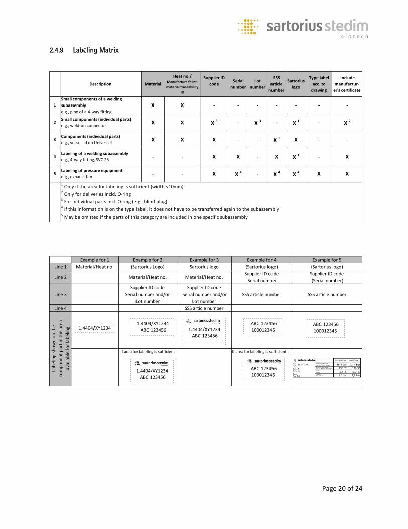
2.4.9 Labeling Matrix
Description Material
Heat no./Manufacturer's int.
material traceability
ID
Supplier ID
codeSerial
number
Lot
number
SSS
article
number
Sartorius
logo
Type label
acc. to
drawing
Include
manufactur-
er's certificate
5
1
2
3
4
Labeling of pressure equipment
e.g., exhaust fan
1 Only if the area for labeling is sufficient (width <10mm)
2 Only for deliveries incld. O-ring 3 For individual parts incl. O-ring (e.g., blind plug) 4 If this information is on the type label, it does not have to be transferred again to the subassembly5 May be omitted if the parts of this category are included in one specific subassembly
Small components of a welding
subassembly
e.g., pipe of a 4-way fitting
Small components (individual parts)
e.g., weld-on connector
Components (individual parts)
e.g., vessel lid on Univessel
Labeling of a welding subassembly
e.g., 4-way fitting, SVC 25
X X 1X X -
- X 4- X
-
XX 4 X 4
X X 1 -
X
X
-
- X X
X - --
-
X -X - -- - --
X -X X 5 X 2- X 1 -X 3
Example for 1 Example for 2 Example for 3 Example for 4 Example for 5
Line 1 Material/Heat no. (Sartorius Logo) Sartorius logo (Sartorius logo) (Sartorius logo)
Line 2 Material/Heat no. Material/Heat no.Supplier ID code
Serial number
Supplier ID code
(Serial number)
Line 3
Supplier ID code
Serial number and/or
Lot number
Supplier ID code
Serial number and/or
Lot number
SSS article number SSS article number
Line 4 SSS article number
If area for labeling is sufficient If area for labeling is sufficient
Labe
ling
sho
wn
on
the
com
pone
nt p
art
in t
he a
rea
avai
labl
e fo
r la
belin
g 1.4404/XY1234ABC 123456
1.4404/XY1234
ABC 1234561.4404/XY1234
1.4404/XY1234ABC 123456
ABC 123456
100012345
ABC 123456100012345
ABC 123456
100012345
Page 21 of 24
2.5 Documentation Matrix 2.5.1 Documentation Matrix The drawings of the subassemblies show whether the latter are to be used in the product-contacted or the non-sterile area. Regardless of the area of use, the subassemblies must be supplied with certificates to SSS. This is indicated in the documentation matrix (available in the download sector) and must be documented on the manufacturer’s certificate. 2.5.2 Document Filing / Electronic Transmission All documents required must be transmitted electronically. DIN EN 10204 explicitly states that inspection certificates are to be stored and passed on by transmission in electronic form, excluding regular mail (post). This enables faster sending of inspection certificates and facilitates electronic archiving. SSS shall provide its suppliers with an internet platform for filing documents. The Supplier shall expressly request such access from SSS. Certificates and materials (e.g., gaskets, sealing elements, plastics) may not be old. All certificates transmitted shall be legible. 2.5.3 Documentation on Welded Joints / List of Welded Joints If subassemblies are assembled by welded joints that are located in the product-contacted area or are pressure vessels (PED), documentation on such welded joints is required. For this purpose, please use the SSS template for welded joint documents (available as a downloadable file). 2.5.4 Pressure Equipment
All products based on PED 97/23/EC (will be 2014/68/EC) are to be manufactured according to the German AD 2000 Code available in English. The manufacturer (Supplier) must have the corresponding approval. Persons involved in the manufacture of pressure equipment must have the specific professional knowledge and certified authorization to perform their tasks for such equipment.
If ASME Section VIII Division 1 (Boiler & Pressure Vessel Code) is applied, the requirements of this code shall apply. The manufacturer (Supplier) must have the corresponding approval. Persons involved in the manufacture of such pressure vessels must have the specific professional knowledge and certified authorization to perform their tasks for such equipment.
If SELO (Special Equipment Licensing Office) standards are specified for pressure vessels according to Chinese requirements, the manufacturer (Supplier) must have the corresponding approval. Persons involved in the manufacture of such pressure vessels must have the specific professional knowledge and certified authorization to perform their tasks for such equipment.
Pressure vessels shall be manufactured, tested, labeled and documented according to the required design code. The prescribed materials must be used and proof of such use must be supplied by furnishing the required material certificates and inspection certificates.
Page 22 of 24
2.6 Specification on Gasket Materials – Standardized Parts 2.6.1 Elastomers General Specifications for Elastomers / Gaskets If components are used in the product-contacted/sterile area, the following conformity certificates /compliance certificates are required: FDA compliance USP (88) Class VI / DIN ISO 10993-1 USP (87) Cytotoxicity / DIN ISO 10993-5 ADI-free (TSE / BSE) RoHS / REACH Material data sheet The certificates must be saved as files to an SSS server by lot (batch) along with the information on the geometric dimensions of the sealing elements (see TCP section Document Filing / Electronic Transmission) 2.6.2 O-rings Manufactured in accordance with DIN ISO 3601 If no special specifications are given for the material, EPDM with 70 (+/- 5%) Shore A, in black with a temperature resistance of 140°C (cross-linked with peroxide) shall automatically be supplied. It is not permitted to manufacture O-rings by bonding the ends of round cord to make a seal. 2.6.3 Clamp Connections / Clamp Gaskets Manufactured according to DIN 32676 If no special specifications are given for the material, EPDM with 70 to 75 (+/- 5%) Shore A, in black with a temperature resistance of at least 140°C (cross-lined with peroxide) shall automatically be supplied. 2.6.4 Flange Gaskets Manufactured according to the series of DIN EN 1514-1 standards “Flanges and their joints - Dimensions of gaskets for PN-designated flanges” Manufactured according to the series of DIN EN 12560 standards “Flanges and their joints - Gaskets for class-designated flanges” according to ANSI/ASME B16.5
Page 23 of 24
2.6.5 Flat Gaskets Flat gaskets shall conform to the specifications on the drawings. 2.6.6 Membranes Membranes shall conform to the specifications on the drawings.
3.0 Packaging and Transportation You will find the General Shipping and Packaging Specifications for Suppliers to Sartorius Stedim Systems GmbH on the website at http://www.sartorius.de/de/agb/
Page 24 of 24
Postscript: Staff members from different specialized departments at SSB worked together in drafting these
Technical Purchasing Conditions.
These TCPs do not claim to be complete and conform to state of the art at the time they were
written.
If any amendments are made to the standards or legal requirements listed in these TCPs, these
must be taken into account accordingly.
If any applicable standards or legal requirements are not mentioned in these TCPs, these shall be
the basis for all deliveries and services rendered hereunder. We request our Suppliers to notify us
of any such omissions that are applicable.
As soon as we have collected a sufficient number of amendment proposals, these Technical
Purchasing Conditions will be revised and reissued. We welcome any suggestions our Suppliers
may have. Published by: Sartorius Stedim Systems GmbH
Robert-Bosch-Strasse 5-7
D-34302 Guxhagen, Germany


![Guideline BFS-RL 07-101 - bauforumstahl e. V....[11] EN ISO 13920 Welding - General tolerances for welded constructions - Dimensions for lengths and angles; shape and position [12]](https://static.fdocuments.us/doc/165x107/5e6bd35ccda09c385f263a80/guideline-bfs-rl-07-101-bauforumstahl-e-v-11-en-iso-13920-welding-general.jpg)