TECHNICAL MANUALerp2web.schillergcpro.com/documents/pdf/03/36/9001.pdf · Part No. 524483 Rev. 3...
29
Part No. 524483 Rev. 3 TECHNICAL MANUAL Safety, Operations, Maintenance, Parts LAWNAIRE IV MODELS 544863B STANDARD MODELS 544881A COMMERCIAL
Transcript of TECHNICAL MANUALerp2web.schillergcpro.com/documents/pdf/03/36/9001.pdf · Part No. 524483 Rev. 3...

Part No. 524483 Rev. 3
TECHNICAL MANUALSafety, Operations, Maintenance, Parts
LAWNAIRE IV
MODELS 544863B STANDARDMODELS 544881A COMMERCIAL

500–11–00–CU 2000 Textron Inc. All Rights Reserved. Lincoln, Nebraska • Printed in U.S.A.
GENERAL INFORMATION
To make sure you are fully aware of safety and serviceinformation, the following two symbols are usedthroughout this manual.
! This “HAZARD” symbol is used to alert you toinformation about unsafe actions or situations, and willbe followed by the word DANGER, WARNING, orCAUTION. Used with the word DANGER it will describeimmediate hazards that may result in severe personalinjury or death. With the word WARNING it will describeunsafe actions or situations that may cause severeinjury, death and/or major equipment or propertydamage. With the word CAUTION it will describe unsafeactions or situations that may cause injury, and/or minorequipment or property damage.
NOTICE This NOTICE symbol is used to alert youto information that describes procedures or tips that willhelp you operate and maintain your equipment properly.
IMPORTANT!
THIS MANUAL WILL AID YOU IN THE SAFEOPERATION AND PROPER MAINTENANCE OFYOUR EQUIPMENT. ANYONE WHO WILL BEOPERATING THE EQUIPMENT SHOULD READ THEMANUAL THOROUGHLY BEFORE ATTEMPTINGOPERATION.
IF ANY PORTION OF THIS MANUAL IS NOT CLEARLYUNDERSTOOD, CONTACT AN AUTHORIZEDDEALER FOR CLARIFICATION.
WARNING!
The information and instructions included inthis manual alert you to certain things youshould do very carefully. If you don’t, you could:• hurt yourself or others • hurt the next person who operates the equipment• damage the equipment.
This manual contains essential operation andsafety information and must remain with the unitat all times, within easy access of any operator.
Additional operator’s manuals are available through yourdealer.
IMPORTANT!
THIS EQUIPMENT SHOULD NOT BE MODIFIED ORADDED TO WITHOUT THE MANUFACTURER’SAUTHORIZATION.
Contact your dealer for correspondence with the factory.
WARNING!
Altering this equipment in any manner whichadversely affects the operation, performance,durability or use may cause hazardousconditions.
PRODUCT REFERENCE
Information in this manual may refer to a specificproduct, brand name, number or tool. Unless specificallystated otherwise, an equivalent product may be used.
ILLUSTRATIONS & SPECIFICATIONS
All information, illustrations and specifications containedin this manual are based on the latest productinformation available at the time of printing. TextronGolf, Turf and Specialty Products reserves the right is tomake changes at any time without notice.
PRODUCT REGISTRATION
Textron Golf, Turf and Specialty Products makes everyeffort to keep owners informed of all safety relatedinformation. Therefore, changes in address and/orownership should be reported to the manufacturer.
Your dealer has REGISTRATION CHANGE forms whichwill be filled out and filed by the dealer for his records, anda copy will be sent to the manufacturer.
For the location of the dealer nearest you, call1–800–228–4444 (for dealer information only)or you may write directly to:
Textron Golf, Turf and Specialty ProductsWarranty Dept.P.O. Box 82409Lincoln, Nebraska 68501–2409

1
INDEXPage
Controls 4. . . . . . . . . . . . . . . . . . . . . . . . . . . . . . . . . . . . . Operation 5. . . . . . . . . . . . . . . . . . . . . . . . . . . . . . . . . . . Owner Registration Inside Front Cover. . . . . . . . . . . . Paint, Touch Up 7. . . . . . . . . . . . . . . . . . . . . . . . . . . . . . Parts Lists
Aerator And Drive Group 10. . . . . . . . . . . . . . . . . Chassis 12. . . . . . . . . . . . . . . . . . . . . . . . . . . . . . . . Controls And Handle Group 14. . . . . . . . . . . . . . . Height Adjuster And Transport Frame 16. . . . . .
Service 6. . . . . . . . . . . . . . . . . . . . . . . . . . . . . . . . . . . . . Service Publications Inside Front Cover. . . . . . . . . . . Set–Up 2. . . . . . . . . . . . . . . . . . . . . . . . . . . . . . . . . . . . . Storage 6. . . . . . . . . . . . . . . . . . . . . . . . . . . . . . . . . . . . . Transporting 7. . . . . . . . . . . . . . . . . . . . . . . . . . . . . . . . . Warranty 21-22. . . . . . . . . . . . . . . . . . . . . . . . . . . . . . . .
MODEL NUMBER ANDSERIAL NUMBER LOCATION
The units model number and serial numbers are printedon the Nameplate/Identification decal located on the leftside of the aerator frame. See Figure 1.
4192
Figure 1. Model Number And Serial Number
SPECIFICATIONSEngine Lawnaire IV Model 544863B
Briggs & Stratton 3.5 HP, 4 cycle,#093452, Type 0141, Trim .01, with 6 to 1gear reducer. Recoil starter and rotarystop switch. Governor set at 3600 ± 100RPM No load, idle speed 2000 RPM. 4 qt. (3.8 L) metal fuel tank.
Lawnaire IV Model 544881AHonda, GX120 K1HX, 4 HP, 4 cycle,with 6 to 1 gear reducer.Recoil start and rotating on/off switch.Governor set at 3600 RPM. No load,
idle speed 1400 ± 100 RPM.0.66 gal. (2.5L) metal fuel tank.
Clutch Belt tightener type – controlled from handle.
Chassis Welded steel construction.
Drive Primary: V belt w/ idler clutch.Secondary: #40 sealed roller chain to tineassembly.Transport: #40 sealed roller chainto water tank.
Axles 5/8″ (16 mm) diameter with needle bearings.
Lubrication Pressure lubrication fittings.
Reduction Speed reduction to aerating tinewheel 8.75 to 1.
Speed Transport: 190 f.p.m. (58 m.p.m.)Aerating: 225 f.p.m. (69 m.p.m.)
Wheels One water tank front 11″ (279 mm)diameter, 6.6 gal. (25 L) capacitymaximum.2 semi–pneumatic rear 8 x 1.75with sealed ball bearings.
Tines 3/4″ (19 mm) coring tines, formedfrom 0.080″ thick chrome–molybdenum alloy steel, hardenedfor long life. 30 tines per unit.
AeratingWidth 19″(483 mm)
AeratingDepth 2 3/4″ (70 mm) maximum
AeratingPattern 3 3/4 x 7″ (95 x 178 mm) on center
Controls Two levers, clutch/throttle andtransport lever on handle.
Net Weight 188 lbs. (85.2 Kg) dry, w/o weight.224 lbs. (101.5 Kg) dry, with weight.274 lbs. (124.1 Kg) with water tank fulland weight installed.
Dimensions Width 28″ (813 mm); height inaerating position 38″ (965 mm);height in transport position 47″(1,194 mm); length 48″ (1,219 mm).
2
SET–UP
WARNING!
• To prevent possible injury to yourself or others,stay clear when cutting banding. Banding isunder tension and can snap back when cut.
1. Cut banding and remove hardware bag, handleassembly and center support from pallet.
2. Attach left side of handle assembly to aerator(curved portion of handle pointing up) using two3/8–16 x 3/4″ screws and lockwashers. Do nottighten hardware at this time.
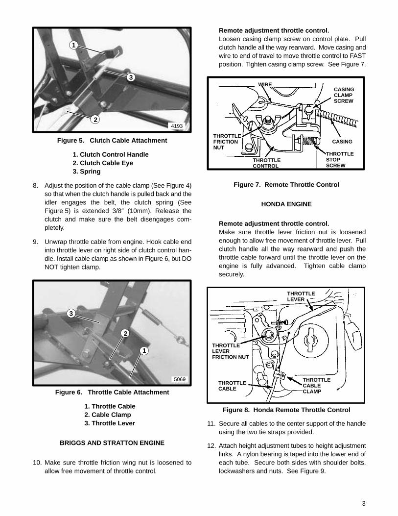
3. Be sure square washer on the tine axle is in properposition (as shown in Figure 2) before installing rightside hardware. Attach right side of handle to aeratorusing one 3/8–16 x 3/4″ screw and lockwasher inlower hole, and one 3/8–16 x 1 1/4″ screw and lock-washer in remaining hole. Attach tine cover to 1 1/4″screw with flatwasher and locknut. Do not tightenhardware at this time.
4197
5328
2
1
3
Figure 2. Handle Attachment
1. Tine Axle Square Washer2. Handle Assembly3. Mounting Hardware
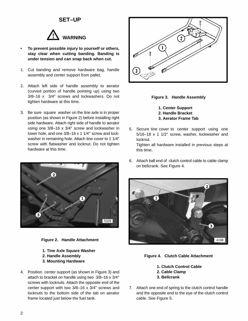
4. Position center support (as shown in Figure 3) andattach to bracket on handle using two 3/8–16 x 3/4″screws with locknuts. Attach the opposite end of thecenter support with two 3/8–16 x 3/4″ screws andlocknuts to the bottom side of the tab on aeratorframe located just below the fuel tank.
Figure 3. Handle Assembly
1. Center Support2. Handle Bracket3. Aerator Frame Tab
5. Secure tine cover to center support using one5/16–18 x 1 1/2″ screw, washer, lockwasher andlocknut.Tighten all hardware installed in previous steps atthis time.
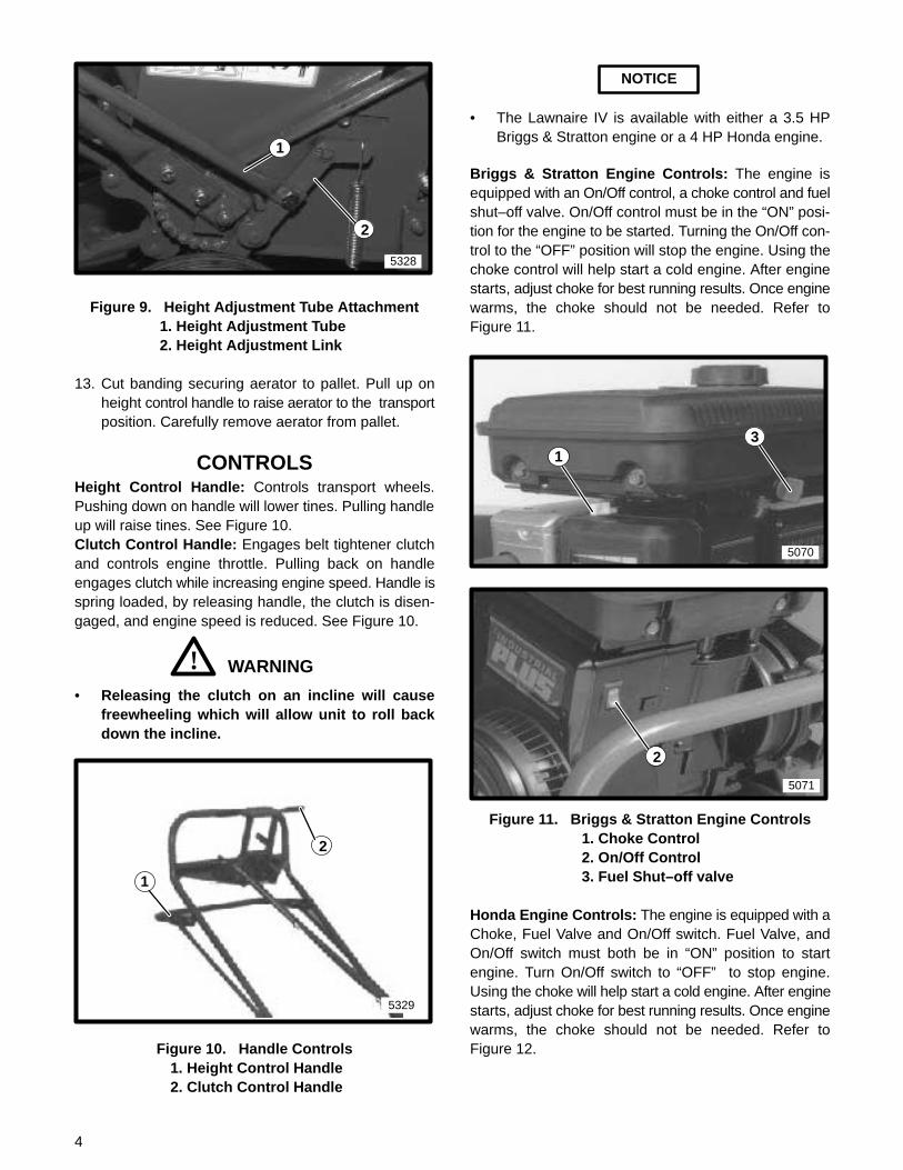
6. Attach ball end of clutch control cable to cable clampon bellcrank. See Figure 4.
4198
1
2
3
Figure 4. Clutch Cable Attachment
1. Clutch Control Cable2. Cable Clamp3. Bellcrank
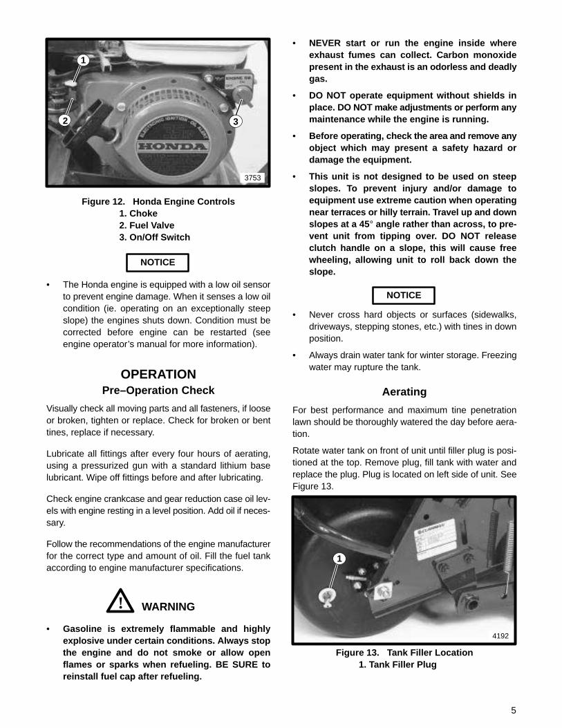
7. Attach one end of spring to the clutch control handleand the opposite end to the eye of the clutch controlcable. See Figure 5.
3
4193
1
2
3
Figure 5. Clutch Cable Attachment
1. Clutch Control Handle2. Clutch Cable Eye3. Spring
8. Adjust the position of the cable clamp (See Figure 4)so that when the clutch handle is pulled back and theidler engages the belt, the clutch spring (SeeFigure 5) is extended 3/8″ (10mm). Release theclutch and make sure the belt disengages com-pletely.
9. Unwrap throttle cable from engine. Hook cable endinto throttle lever on right side of clutch control han-dle. Install cable clamp as shown in Figure 6, but DONOT tighten clamp.
5069
1
2
3
Figure 6. Throttle Cable Attachment
1. Throttle Cable2. Cable Clamp3. Throttle Lever
BRIGGS AND STRATTON ENGINE
10. Make sure throttle friction wing nut is loosened toallow free movement of throttle control.
Remote adjustment throttle control.Loosen casing clamp screw on control plate. Pullclutch handle all the way rearward. Move casing andwire to end of travel to move throttle control to FASTposition. Tighten casing clamp screw. See Figure 7.
THROTTLESTOPSCREW
THROTTLEFRICTIONNUT
WIRE
CASING
CASINGCLAMPSCREW
THROTTLECONTROL
Figure 7. Remote Throttle Control
HONDA ENGINE
Remote adjustment throttle control.Make sure throttle lever friction nut is loosenedenough to allow free movement of throttle lever. Pullclutch handle all the way rearward and push thethrottle cable forward until the throttle lever on theengine is fully advanced. Tighten cable clampsecurely.
THROTTLELEVERFRICTION NUT
THROTTLELEVER
THROTTLECABLE
THROTTLECABLECLAMP
Figure 8. Honda Remote Throttle Control
11. Secure all cables to the center support of the handleusing the two tie straps provided.
12. Attach height adjustment tubes to height adjustmentlinks. A nylon bearing is taped into the lower end ofeach tube. Secure both sides with shoulder bolts,lockwashers and nuts. See Figure 9.
4
5328
2
1
Figure 9. Height Adjustment Tube Attachment1. Height Adjustment Tube2. Height Adjustment Link
13. Cut banding securing aerator to pallet. Pull up onheight control handle to raise aerator to the transportposition. Carefully remove aerator from pallet.
CONTROLSHeight Control Handle: Controls transport wheels.Pushing down on handle will lower tines. Pulling handleup will raise tines. See Figure 10.Clutch Control Handle: Engages belt tightener clutchand controls engine throttle. Pulling back on handleengages clutch while increasing engine speed. Handle isspring loaded, by releasing handle, the clutch is disen-gaged, and engine speed is reduced. See Figure 10.
WARNING!• Releasing the clutch on an incline will cause
freewheeling which will allow unit to roll backdown the incline.
5329
1
2
Figure 10. Handle Controls1. Height Control Handle2. Clutch Control Handle
NOTICE
• The Lawnaire IV is available with either a 3.5 HPBriggs & Stratton engine or a 4 HP Honda engine.
Briggs & Stratton Engine Controls: The engine isequipped with an On/Off control, a choke control and fuelshut–off valve. On/Off control must be in the “ON” posi-tion for the engine to be started. Turning the On/Off con-trol to the “OFF” position will stop the engine. Using thechoke control will help start a cold engine. After enginestarts, adjust choke for best running results. Once enginewarms, the choke should not be needed. Refer toFigure 11.
5070
13
5071
2
Figure 11. Briggs & Stratton Engine Controls1. Choke Control2. On/Off Control3. Fuel Shut–off valve
Honda Engine Controls: The engine is equipped with aChoke, Fuel Valve and On/Off switch. Fuel Valve, andOn/Off switch must both be in “ON” position to startengine. Turn On/Off switch to “OFF” to stop engine.Using the choke will help start a cold engine. After enginestarts, adjust choke for best running results. Once enginewarms, the choke should not be needed. Refer toFigure 12.
5
3753
1
2 3
Figure 12. Honda Engine Controls1. Choke2. Fuel Valve3. On/Off Switch
NOTICE
• The Honda engine is equipped with a low oil sensorto prevent engine damage. When it senses a low oilcondition (ie. operating on an exceptionally steepslope) the engines shuts down. Condition must becorrected before engine can be restarted (seeengine operator’s manual for more information).
OPERATIONPre–Operation Check
Visually check all moving parts and all fasteners, if looseor broken, tighten or replace. Check for broken or benttines, replace if necessary.
Lubricate all fittings after every four hours of aerating,using a pressurized gun with a standard lithium baselubricant. Wipe off fittings before and after lubricating.
Check engine crankcase and gear reduction case oil lev-els with engine resting in a level position. Add oil if neces-sary.
Follow the recommendations of the engine manufacturerfor the correct type and amount of oil. Fill the fuel tankaccording to engine manufacturer specifications.
WARNING!• Gasoline is extremely flammable and highly
explosive under certain conditions. Always stopthe engine and do not smoke or allow openflames or sparks when refueling. BE SURE toreinstall fuel cap after refueling.
• NEVER start or run the engine inside whereexhaust fumes can collect. Carbon monoxidepresent in the exhaust is an odorless and deadlygas.
• DO NOT operate equipment without shields inplace. DO NOT make adjustments or perform anymaintenance while the engine is running.
• Before operating, check the area and remove anyobject which may present a safety hazard ordamage the equipment.
• This unit is not designed to be used on steepslopes. To prevent injury and/or damage toequipment use extreme caution when operatingnear terraces or hilly terrain. Travel up and downslopes at a 45 ° angle rather than across, to pre-vent unit from tipping over. DO NOT releaseclutch handle on a slope, this will cause freewheeling, allowing unit to roll back down theslope.
NOTICE
• Never cross hard objects or surfaces (sidewalks,driveways, stepping stones, etc.) with tines in downposition.
• Always drain water tank for winter storage. Freezingwater may rupture the tank.
Aerating
For best performance and maximum tine penetrationlawn should be thoroughly watered the day before aera-tion.
Rotate water tank on front of unit until filler plug is posi-tioned at the top. Remove plug, fill tank with water andreplace the plug. Plug is located on left side of unit. SeeFigure 13.
4192
1
Figure 13. Tank Filler Location1. Tank Filler Plug
6
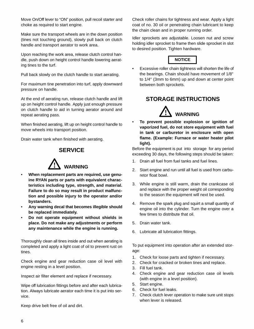
Move On/Off lever to “ON” position, pull recoil starter andchoke as required to start engine.
Make sure the transport wheels are in the down position(tines not touching ground), slowly pull back on clutchhandle and transport aerator to work area.
Upon reaching the work area, release clutch control han-dle, push down on height control handle lowering aerat-ing tines to the turf.
Pull back slowly on the clutch handle to start aerating.
For maximum tine penetration into turf, apply downwardpressure on handle.
At the end of aerating run, release clutch handle and liftup on height control handle. Apply just enough pressureon clutch handle to aid in turning aerator around andrepeat aerating pass.
When finished aerating, lift up on height control handle tomove wheels into transport position.
Drain water tank when finished with aerating.
SERVICE
WARNING!• When replacement parts are required, use genu-
ine RYAN parts or parts with equivalent charac-teristics including type, strength, and material.Failure to do so may result in product malfunc-tion and possible injury to the operator and/orbystanders.
• Any warning decal that becomes illegible shouldbe replaced immediately.
• Do not operate equipment without shields inplace. Do not make any adjustments or performany maintenance while the engine is running.
Thoroughly clean all tines inside and out when aerating iscompleted and apply a light coat of oil to prevent rust ontines.
Check engine and gear reduction case oil level withengine resting in a level position.
Inspect air filter element and replace if necessary.
Wipe off lubrication fittings before and after each lubrica-tion. Always lubricate aerator each time it is put into ser-vice.
Keep drive belt free of oil and dirt.
Check roller chains for tightness and wear. Apply a lightcoat of no. 30 oil or penetrating chain lubricant to keepthe chain clean and in proper running order.
Idler sprockets are adjustable. Loosen nut and screwholding idler sprocket to frame then slide sprocket in slotto desired position. Tighten hardware.
NOTICE
• Excessive roller chain tightness will shorten the life ofthe bearings. Chain should have movement of 1/8″to 1/4″ (3mm to 6mm) up and down at center pointbetween both sprockets.
STORAGE INSTRUCTIONS
WARNING!• To prevent possible explosion or ignition of
vaporized fuel, do not store equipment with fuelin tank or carburetor in enclosure with openflame. (Example: Furnace or water heater pilotlight).
Before the equipment is put into storage for any periodexceeding 30 days, the following steps should be taken:
1. Drain all fuel from fuel tanks and fuel lines.
2. Start engine and run until all fuel is used from carbu-retor float bowl.
3. While engine is still warm, drain the crankcase oiland replace with the proper weight oil correspondingto the season the equipment will next be used.
4. Remove the spark plug and squirt a small quantity ofengine oil into the cylinder. Turn the engine over afew times to distribute that oil.
5. Drain water tank.
6. Lubricate all lubrication fittings.
To put equipment into operation after an extended stor-age:
1. Check for loose parts and tighten if necessary.2. Check for cracked or broken tines and replace.3. Fill fuel tank.4. Check engine and gear reduction case oil levels
(with engine in a level position).5. Start engine.6. Check for fuel leaks.7. Check clutch lever operation to make sure unit stops
when lever is released.

7
TOUCH UP PAINTRansomes Green (medium green)16 oz. (0.5L) spray order no. 838140. . . . . . . . . . . . . . 1 qt. (0.95L) can order no. 838141. . . . . . . . . . . . . . . .
Safety Yellow16 oz. (0.5L) spray order no. 833252. . . . . . . . . . . . . . 1 qt. (0.95L) can order no. 833251. . . . . . . . . . . . . . . .
TRANSPORTINGIf tote trailer is used, weight from aerator frame bar mustbe removed and locking shaft installed through aeratorframe.
Removal of weight bar from unit and draining water tank,will decrease the weight for easier loading on vehicle ortrailer.
Remove weight bar by turning lever to the up position andsliding weight bar out. Take care, the bar weighs approxi-mately 20 lbs.
5072
1
2
Figure 14
1. Lever2. Weight
Close fuel shut off valve before transporting unit.
8
M4 M5 M6 M7 M8 M10 M12 M14 M16 M18 M20 M22 M24 M27
N·m 2 4 7 11 18 32 58 94 144 190 260 368 470 707
ft.-lb. 1.5 3 5.2 8.2 13.5 24 43.5 70.5 108 142 195 276 353 530
N·m 3 6 10 16 25 47 83 133 196 269 366 520 664 996
ft.-lb. 2.2 4.5 7.5 12 18.8 35.2 62.2 100 147 202 275 390 498 747
N·m 3.6 7 11 20 29 58 100 159 235 323 440 628 794 1205
ft.-lb. 2.7 5.2 8.2 15 21.8 43.5 75 119 176 242 330 471 596 904
1/4 5/16 3/8 7/16 1/2 9/16 5/8 3/4 7/8 1 1 1/8
ft.-lb. 9 18 31 50 75 110 150 250 378 583 782
N·m 12 24 42 68 102 150 203 339 513 790 1060
ft.-lb. 13 28 46 75 115 165 225 370 591 893 1410
N·m 18 38 62 108 156 224 305 502 801 1211 1912
ft.-lb. 24 40
N·m 33 54
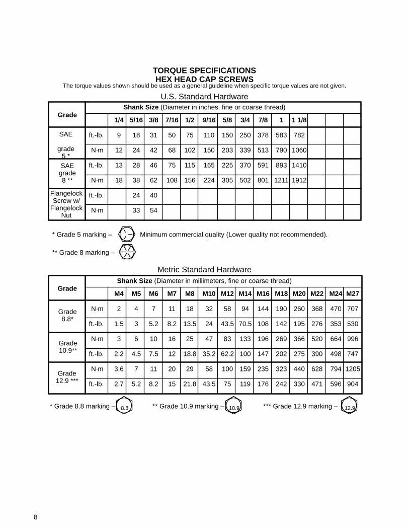
TORQUE SPECIFICATIONSHEX HEAD CAP SCREWS
* Grade 5 marking – Minimum commercial quality (Lower quality not recommended).
U.S. Standard Hardware
GradeShank Size (Diameter in inches, fine or coarse thread)
SAE
grade5 *SAE
grade8 **
FlangelockScrew w/
FlangelockNut
The torque values shown should be used as a general guideline when specific torque values are not given.
** Grade 8 marking –
GradeShank Size (Diameter in millimeters, fine or coarse thread)
Grade8.8*
Grade10.9**
Grade12.9 ***
Metric Standard Hardware
* Grade 8.8 marking – ** Grade 10.9 marking – *** Grade 12.9 marking –8.8 10.9 12.9

9
NOTES
10
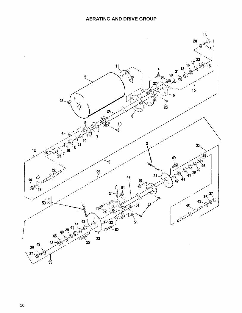
AERATING AND DRIVE GROUP
◊◊◊

11
AERATING AND DRIVE GROUP
1◊ 540291 Chain, #40 sealed roller 1. . . . . . . . * 522122 •Link, connector 1. . . . . . . . . . . . . . . 2 547889 Chain, #40 sealed roller 1. . . . . . . . * 522122 •Link, connector 1. . . . . . . . . . . . . . . 3 547920 Tank assembly, complete 1. . . . . . . 4 306932 •Nut, 5/16–18 12. . . . . . . . . . . . . . . 5 522414 •Tank, water 1. . . . . . . . . . . . . . . . . . 6 522480 •Gasket, 4 1/2″ diameter 1. . . . . . . . 7 522481 •Gasket, 3″ diameter 1. . . . . . . . . . . 8 522586 •Plate, cap, 3″ diameter 1. . . . . . . . 9 522674 •Sprocket, tank 1. . . . . . . . . . . . . . . . 10 523912 •Fitting, lubrication 1. . . . . . . . . . . . . 11 545887 •Ring, split 2. . . . . . . . . . . . . . . . . . . . 12 547855 •Kit, needle bearing 1. . . . . . . . . . . . 13 303269 •• Lockwasher, 7/16 2. . . . . . . . . . . . 14 304364 •• Nut, lock 7/16–14 2. . . . . . . . . . . . 15 515891 •• Spacer, large As Req’d. . . . . . . . . 16 523241 •• Seal, v–ring 2. . . . . . . . . . . . . . . . . 17 523829 •• Washer, thrust 2. . . . . . . . . . . . . . . 18 523832 •• Bearing, needle 2. . . . . . . . . . . . . . 19 523885 •• Bushing 2. . . . . . . . . . . . . . . . . . . . . 20 524807 •• Washer, square 2. . . . . . . . . . . . . . 21 523939 •• Shim, small As Req’d. . . . . . . . . . 22 523947 •• Shaft, axle 1. . . . . . . . . . . . . . . . . . 23 548478 •• Shim, large As Req’d. . . . . . . . . . . 24 547873 •Tube, drive 1. . . . . . . . . . . . . . . . . . . 25 548224 •Fitting, lubrication 1. . . . . . . . . . . . . 26 548604 •Screw, flangelock, 5/16–18x3/4 3. . .
27 548911 •Nut, flangelock 5/16–18 3. . . . . . . . 28 821274 •Plug, drain 1. . . . . . . . . . . . . . . . . . . 29 547921 Tine wheel assembly, complete 1. . 30 306501 •Screw, 5/16–18 x 1 1/2 3. . . . . . . . 31 521582 •Sprocket 1. . . . . . . . . . . . . . . . . . . . . 32 521588 •Bushing 3. . . . . . . . . . . . . . . . . . . . . 33 522229 •Sprocket, drive 1. . . . . . . . . . . . . . . 34 522361 •Tine, 3/4″ (19 mm) 30. . . . . . . . . . 35 547855 •Kit, needle bearing 1. . . . . . . . . . . . 36 303269 •• Lockwasher, 7/16 2. . . . . . . . . . . . 37 304364 •• Nut, lock 7/16–14 2. . . . . . . . . . . . 38 515891 •• Spacer, large As Req’d. . . . . . . . . 39 523241 •• Seal, v–ring 2. . . . . . . . . . . . . . . . . 40 523829 •• Washer, thrust 2. . . . . . . . . . . . . . . 41 523832 •• Bearing, needle 2. . . . . . . . . . . . . . 42 523885 •• Bushing 2. . . . . . . . . . . . . . . . . . . . . 43 523890 •• Washer, square 2. . . . . . . . . . . . . . 44 523939 •• Shim, small As Req’d. . . . . . . . . . 45 523947 •• Shaft, axle 1. . . . . . . . . . . . . . . . . . 46 548478 •• Shim, large As Req’d. . . . . . . . . . . 47 547871 •Wheel, tine 1. . . . . . . . . . . . . . . . . . . 48 548224 •Fitting, lube 2. . . . . . . . . . . . . . . . . . 49 548604 •Screw, flangelock, 5/16–18 x 3/4 3. . 50 548911 •Nut, flangelock 5/16–18 3. . . . . . . . 51 800290 •Nut, lock 5/16–18 63. . . . . . . . . . . 52 800606 •Bolt, carriage, 5/16–18 x 1 1/2 60. . 53◊◊ 547888 Chain, #40 sealed (74 links with
connector) 1. . . . . . . . . . . . . . . . . . . .
Ref. No.
Part No. Description
No. Req’d
No. Req’dDescription
Part No.
Ref. No.
• INDENTED PART NAMES INDICATE THESE PARTS ARE INCLUDED IN PRECEDING ASSEMBLY.
* Not illustrated.
◊ For units produced after 10-09-95.
◊◊ For units produced prior to 10-09-95.
12
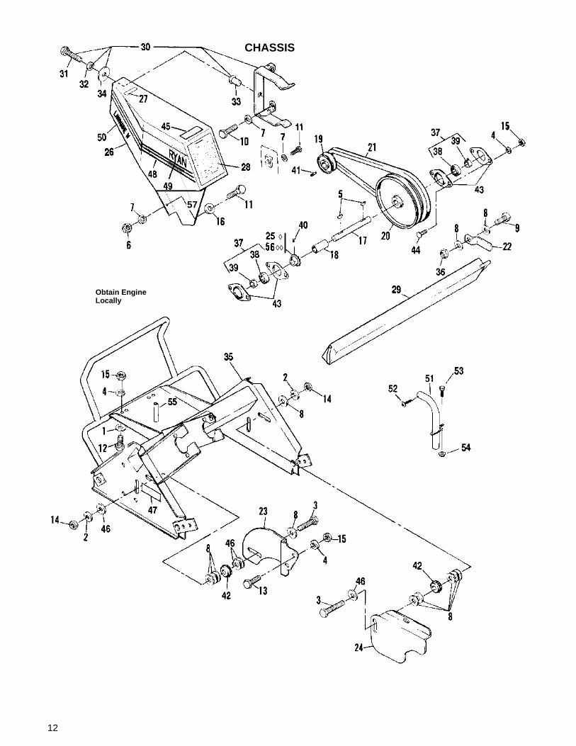
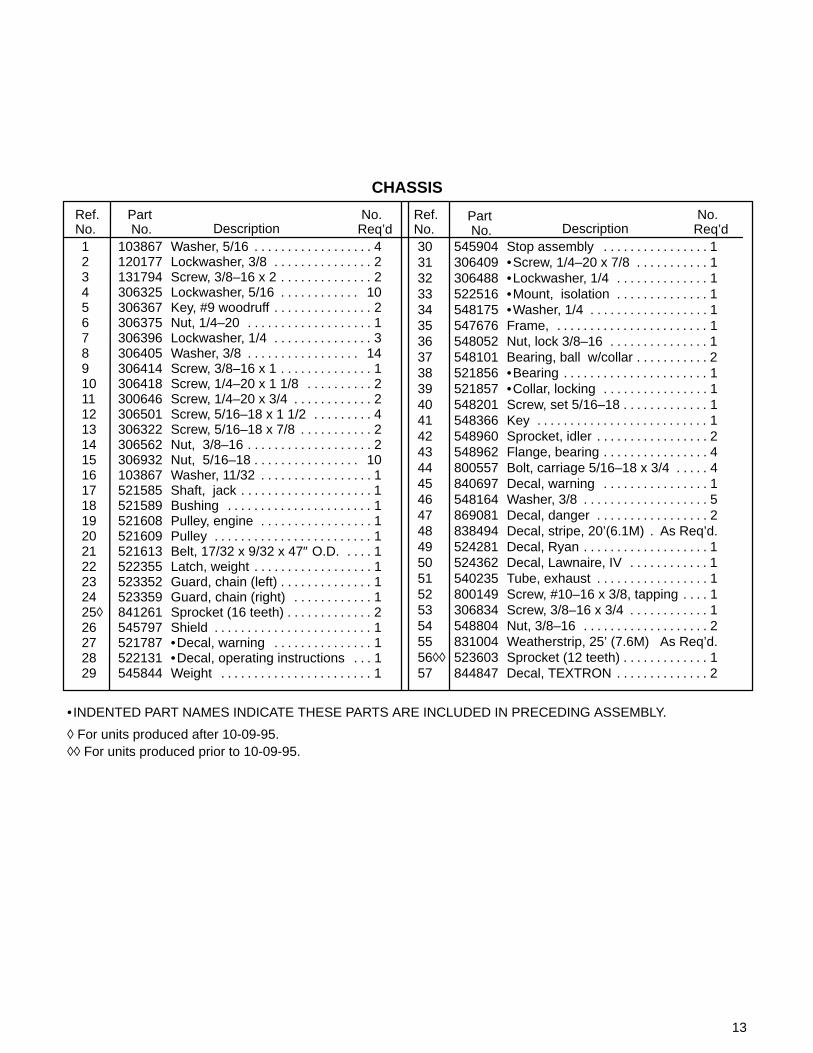
CHASSIS
Obtain EngineLocally
◊◊◊
57
13
CHASSIS
Ref. No.
Part No. Description
No. Req’d
No. Req’dDescription
Part No.
Ref. No.
1 103867 Washer, 5/16 4. . . . . . . . . . . . . . . . . . 2 120177 Lockwasher, 3/8 2. . . . . . . . . . . . . . . 3 131794 Screw, 3/8–16 x 2 2. . . . . . . . . . . . . . 4 306325 Lockwasher, 5/16 10. . . . . . . . . . . . 5 306367 Key, #9 woodruff 2. . . . . . . . . . . . . . . 6 306375 Nut, 1/4–20 1. . . . . . . . . . . . . . . . . . . 7 306396 Lockwasher, 1/4 3. . . . . . . . . . . . . . . 8 306405 Washer, 3/8 14. . . . . . . . . . . . . . . . . 9 306414 Screw, 3/8–16 x 1 1. . . . . . . . . . . . . . 10 306418 Screw, 1/4–20 x 1 1/8 2. . . . . . . . . . 11 300646 Screw, 1/4–20 x 3/4 2. . . . . . . . . . . . 12 306501 Screw, 5/16–18 x 1 1/2 4. . . . . . . . . 13 306322 Screw, 5/16–18 x 7/8 2. . . . . . . . . . . 14 306562 Nut, 3/8–16 2. . . . . . . . . . . . . . . . . . . 15 306932 Nut, 5/16–18 10. . . . . . . . . . . . . . . . 16 103867 Washer, 11/32 1. . . . . . . . . . . . . . . . . 17 521585 Shaft, jack 1. . . . . . . . . . . . . . . . . . . . 18 521589 Bushing 1. . . . . . . . . . . . . . . . . . . . . . 19 521608 Pulley, engine 1. . . . . . . . . . . . . . . . . 20 521609 Pulley 1. . . . . . . . . . . . . . . . . . . . . . . . 21 521613 Belt, 17/32 x 9/32 x 47″ O.D. 1. . . . 22 522355 Latch, weight 1. . . . . . . . . . . . . . . . . . 23 523352 Guard, chain (left) 1. . . . . . . . . . . . . . 24 523359 Guard, chain (right) 1. . . . . . . . . . . . 25◊ 841261 Sprocket (16 teeth) 2. . . . . . . . . . . . . 26 545797 Shield 1. . . . . . . . . . . . . . . . . . . . . . . . 27 521787 •Decal, warning 1. . . . . . . . . . . . . . . 28 522131 •Decal, operating instructions 1. . . 29 545844 Weight 1. . . . . . . . . . . . . . . . . . . . . . .
30 545904 Stop assembly 1. . . . . . . . . . . . . . . . 31 306409 •Screw, 1/4–20 x 7/8 1. . . . . . . . . . . 32 306488 •Lockwasher, 1/4 1. . . . . . . . . . . . . . 33 522516 •Mount, isolation 1. . . . . . . . . . . . . . 34 548175 •Washer, 1/4 1. . . . . . . . . . . . . . . . . . 35 547676 Frame, 1. . . . . . . . . . . . . . . . . . . . . . . 36 548052 Nut, lock 3/8–16 1. . . . . . . . . . . . . . . 37 548101 Bearing, ball w/collar 2. . . . . . . . . . . 38 521856 •Bearing 1. . . . . . . . . . . . . . . . . . . . . . 39 521857 •Collar, locking 1. . . . . . . . . . . . . . . . 40 548201 Screw, set 5/16–18 1. . . . . . . . . . . . . 41 548366 Key 1. . . . . . . . . . . . . . . . . . . . . . . . . . 42 548960 Sprocket, idler 2. . . . . . . . . . . . . . . . . 43 548962 Flange, bearing 4. . . . . . . . . . . . . . . . 44 800557 Bolt, carriage 5/16–18 x 3/4 4. . . . . 45 840697 Decal, warning 1. . . . . . . . . . . . . . . . 46 548164 Washer, 3/8 5. . . . . . . . . . . . . . . . . . . 47 869081 Decal, danger 2. . . . . . . . . . . . . . . . . 48 838494 Decal, stripe, 20’(6.1M) As Req’d.. 49 524281 Decal, Ryan 1. . . . . . . . . . . . . . . . . . . 50 524362 Decal, Lawnaire, IV 1. . . . . . . . . . . . 51 540235 Tube, exhaust 1. . . . . . . . . . . . . . . . . 52 800149 Screw, #10–16 x 3/8, tapping 1. . . . 53 306834 Screw, 3/8–16 x 3/4 1. . . . . . . . . . . . 54 548804 Nut, 3/8–16 2. . . . . . . . . . . . . . . . . . . 55 831004 Weatherstrip, 25’ (7.6M) As Req’d.56◊◊ 523603 Sprocket (12 teeth) 1. . . . . . . . . . . . . 57 844847 Decal, TEXTRON 2. . . . . . . . . . . . . .
• INDENTED PART NAMES INDICATE THESE PARTS ARE INCLUDED IN PRECEDING ASSEMBLY.
◊ For units produced after 10-09-95.◊◊ For units produced prior to 10-09-95.

14
CONTROLS AND HANDLE GROUP

15
CONTROLS AND HANDLE GROUP
1 103867 Washer, 5/16 3. . . . . . . . . . . . . . . . . . 2 111898 Clamp 1. . . . . . . . . . . . . . . . . . . . . . . . 3 120052 Lockwasher, #10 1. . . . . . . . . . . . . . . 4 120177 Lockwasher, 3/8 4. . . . . . . . . . . . . . . 5 306325 Lockwasher, 5/16 2. . . . . . . . . . . . . . 6 306328 Pin, cotter 3/32 x 3/4 1. . . . . . . . . . . 7 306405 Washer, 3/8 1. . . . . . . . . . . . . . . . . . . 8 306409 Screw, 1/4–20 x 7/8 2. . . . . . . . . . . . 9 306322 Screw, 5/16–18 x 7/8 1. . . . . . . . . . . 10 306501 Screw, 5/16–18 x 1 1/2 1. . . . . . . . . 11 306514 Screw, #10–24 x 1/2 1. . . . . . . . . . . 12 306531 Nut, #10–24 1. . . . . . . . . . . . . . . . . . . 13 306834 Screw, 3/8–16 x 3/4 6. . . . . . . . . . . . 14 306835 Screw, 3/8–16 x 1 1/4 2. . . . . . . . . . 15 306932 Nut, 5/16–18 1. . . . . . . . . . . . . . . . . . 16 308090 Washer, 1/4 4. . . . . . . . . . . . . . . . . . . 17 548157 Washer, 33/64 3. . . . . . . . . . . . . . . . . 18 521712 Decal, operating 1. . . . . . . . . . . . . . . 19 523000 Lever, throttle 1. . . . . . . . . . . . . . . . . 20 523139 Grip, handle 2. . . . . . . . . . . . . . . . . . . 21 523363 Bushing, snap 2. . . . . . . . . . . . . . . . . 22 524808 Clamp, cable 1. . . . . . . . . . . . . . . . . . 23 523898 Spring 1. . . . . . . . . . . . . . . . . . . . . . . .
24 547445 Cable, clutch 1. . . . . . . . . . . . . . . . . . 25 547646 Handle, clutch 1. . . . . . . . . . . . . . . . . 26 540311 Handle, aerator 1. . . . . . . . . . . . . . . . 27 547735 Cable, throttle (Honda) 1. . . . . . . . . 28 547854 Bellcrank 1. . . . . . . . . . . . . . . . . . . . . 29 548225 Fitting, lubrication 1. . . . . . . . . . . . . . 30 548804 Nut, flangelock 3/8–16 6. . . . . . . . . . 31 548942 Pulley, idler 1. . . . . . . . . . . . . . . . . . . 32 551094 Screw, 3/8–16 x 1 3/4 1. . . . . . . . . . 33 602937 Spring 1. . . . . . . . . . . . . . . . . . . . . . . . 34 800059 Nut, lock 1/4–20 2. . . . . . . . . . . . . . . 35 800290 Nut, lock 5/16–18 1. . . . . . . . . . . . . . 36 800292 Nut, 3/8–16 1. . . . . . . . . . . . . . . . . . . 37 800385 Screw, flangelock 3/8–16 x 3/4 1. . 38 817019 Bushing 2. . . . . . . . . . . . . . . . . . . . . . 39 540218 Cable, throttle (B&S) 1. . . . . . . . . . . 40 320107 •Tie, plastic 2. . . . . . . . . . . . . . . . . . . 41 524467 Cover, tine 1. . . . . . . . . . . . . . . . . . . . 42 515755 Clip 1. . . . . . . . . . . . . . . . . . . . . . . . . . 43 300646 Screw, 1/4–20 x 3/4 1. . . . . . . . . . . . 44 524281 Decal, RYAN 1. . . . . . . . . . . . . . . . . . 45 838494 Decal, stripe, 20’(6.1M) As Req’d.. 46 524476 Support, center 1. . . . . . . . . . . . . . . .
Ref. No.
Part No. Description
No. Req’d
No. Req’dDescription
Part No.
Ref. No.
• INDENTED PART NAMES INDICATE THESE PARTS ARE INCLUDED IN PRECEDING ASSEMBLY.

16
HEIGHT ADJUSTER & TRANSPORT FRAME
1
2
34
5
6
7
8
9
10
11
12
13
14
15
16
17
1819
20
21
22
23
2425
26
27
28
29
30
3128
2

17
HEIGHT ADJUSTER & TRANSPORT FRAME
1 120177 Lockwasher, 3/8 2. . . . . . . . . . . . . . . 2 304636 Pin, cotter 1/8 x 1 2. . . . . . . . . . . . . 3 306325 Lockwasher, 5/16 2. . . . . . . . . . . . . . 4 306414 Screw, 3/8–16 x 1 2. . . . . . . . . . . . . . 5 306562 Nut, 3/8–16 2. . . . . . . . . . . . . . . . . . . 6 306835 Screw, 3/8–16 x 1 1/4 2. . . . . . . . . . 7 306932 Nut, 5/16–18 2. . . . . . . . . . . . . . . . . . 8 306956 Pin, cotter 1/8 x 3/4 2. . . . . . . . . . . . 9 306981 Washer, 3/8 4. . . . . . . . . . . . . . . . . . . 10 548157 Washer, 33/64 3. . . . . . . . . . . . . . . . . 11 516634 Pin, clevis 2. . . . . . . . . . . . . . . . . . . . . 12 518438 Bushing 2. . . . . . . . . . . . . . . . . . . . . . 13 524633 Screw, shoulder, 5/16–18 1. . . . . . . 14 524638 Tube, control 2. . . . . . . . . . . . . . . . . . 15 524649 Handle, height adjustment 1. . . . . . 16 524643 Bearing, split 4. . . . . . . . . . . . . . . . . .
17 545931 Wheel 2. . . . . . . . . . . . . . . . . . . . . . . . 18 547675 Frame, transport 1. . . . . . . . . . . . . . . 19 522440 •Spacer 2. . . . . . . . . . . . . . . . . . . . . . 20 548804 •Nut, 3/8–16 flangelock 4. . . . . . . . . 21 800385 •Screw, flangelock, 3/8–16 x 3/4 4. . . 22 547707 Link Kit 1. . . . . . . . . . . . . . . . . . . . . . . 23 521679 •Bushing 2. . . . . . . . . . . . . . . . . . . . . 24 522343 •Link, height adjustment 2. . . . . . . . 25 523366 •Spring 2. . . . . . . . . . . . . . . . . . . . . . . 26 523423 •Link, height adjustment 2. . . . . . . . 27 548165 Washer, 21/32 2. . . . . . . . . . . . . . . . . 28 604174 Washer, 3/8 4. . . . . . . . . . . . . . . . . . . 29 800292 Nut, lock 3/8–16 2. . . . . . . . . . . . . . . 30 830165 Bushing 2. . . . . . . . . . . . . . . . . . . . . . 31 548164 Washer, 3/8 2. . . . . . . . . . . . . . . . . . .
Ref. No.
Part No. Description
No. Req’d
No. Req’dDescription
Part No.
Ref. No.
• INDENTED PART NAMES INDICATE THESE PARTS ARE INCLUDED IN PRECEDING ASSEMBLY.

18

19
HIGHLY RECOMMENDED!An Excellent Video Showing:• Pre-operational Checks• Engine Start-up• Aeration• Loading and Unloading• Daily and Periodic Maintenance• Storage Procedures for the Lawnaire IV and Lawnaire V Aerators
VHS Format 14 Minute Running Time Cost $10.00
ORDER INFORMATION
Ship to: Attn.
Company Name:
Street Address:
City, State, Zip:
E260030 LAWNAIRE IV & LAWNAIRE V VIDEO
$2.50 Shipping and Handling Per Tape
Part No. Description Qty. Each Total
Total Enclosed
10.00
2.50
Make checks payable to Textron Turf Care and Specialty ProductsReturn to: Textron Turf Care and Specialty Products
Attn: Nichole Deschler1721 Packard AvenueRacine, WI 53403–2564
(Please allow 2 weeks for delivery)
EASY TO FOLLOWOPERATION AND MAINTENANCEVIDEO TAPE
LAWNAIRE IVAND
LAWNAIRE VVIDEO

20

21
TEXTRON TURF CARE AND SPECIALTY PRODUCTS WARRANTY
Textron Turf Care And Specialty Products warrants for one (1) year each new Ransomes/Cushman/Ryan unit orserialized accessories except for the Envirojet high pressure injection system components which are warranted for one(1) year or 200 hours whichever occurs first, according to the following terms:This warranty extends to the original retail purchaser only and commences on the date of original retail purchase.Accordingly this warranty is not transferable to any subsequent purchasers.Any part of the Ransomes/Cushman/Ryan unit or serialized accessory manufactured by Textron Turf Care AndSpecialty Products and found in the reasonable judgement of Textron Turf Care And Specialty Products to be defectivein material or workmanship will be repaired or replaced by an authorized Ransomes/Cushman/Ryan dealer withoutcharge for parts and labor.The Ransomes/Cushman/Ryan unit or serialized accessory including any defective part must be returned to anauthorized Ransomes/Cushman/Ryan dealer within the warranty period. The expense of returning theRansomes/Cushman/Ryan unit or serialized accessory to an authorized dealer for warranty service and the expenseof returning it back to the owner after repair or replacement will be paid for by the owner. Textron Turf Care And SpecialtyProducts’s responsibility in respect to claims is limited to making the required repairs or replacements, and no claim ofbreach of warranty shall be cause for cancellation or rescission of the contract of sale of anyRansomes/Cushman/Ryan unit or serialized accessory.Proof of purchase will be required by the authorized Ransomes/Cushman/Ryan dealer to substantiate any warrantyclaim. All warranty work must be performed by an authorized Ransomes/Cushman/Ryan dealer.Textron Turf Care And Specialty Products makes no warranty with respect to engines, tires, batteries, regulators,starter–generators, electric motors, or other parts not of their manufacture as such parts are usually warrantedseparately by their respective manufacturers.This warranty does not include service items subject to normal wear, such as filters, spark plugs, ignition points, brakeand clutch linings, belts, light bulbs, fuses, bearings, electrical contacts, etc.This warranty does not cover any Ransomes/Cushman/Ryan unit or serialized accessory that has been subject tomisuse, neglect, negligence, or accident, or that has been operated or maintained in any way contrary to the operatingor maintenance instructions as specified in the Ransomes/Cushman/Ryan Operator’s Manual. The warranty does notapply to any Ransomes/Cushman/Ryan unit or serialized accessory that has been altered or modified so as toadversely affect the units operation, performance or durability or that has been altered or modified so as to change itsintended use. In addition, the warranty does not extend to repairs made necessary by normal wear, or by the use of partsor accessories which in the reasonable judgement of Textron Turf Care And Specialty Products are either incompatiblewith the Ransomes/Cushman/Ryan unit or adversely affect its operation, performance or durability.Textron Turf Care And Specialty Products reserves the right to change or improve the design of anyRansomes/Cushman/Ryan unit or serialized accessory without assuming any obligation to modify any unit previouslymanufactured.
ALL OTHER WARRANTIES OR CONDITIONS, EXPRESS OR IMPLIED, INCLUDING MERCHANTABILITY,FITNESS FOR A PARTICULAR PURPOSE OR OTHERWISE ARE EXPRESSLY EXCLUDED. THERE ARE NOWARRANTIES WHICH EXTEND BEYOND THE DESCRIPTION ON THE FACE HEREOF. ANY ACTION FORBREACH OF WARRANTY MUST BE COMMENCED NO LATER THAN ONE YEAR FROM THE DATE OF DELIVERY.
TEXTRON TURF CARE AND SPECIALTY PRODUCTS’S OBLIGATION UNDER THIS WARRANTY IS STRICTLYAND EXCLUSIVELY LIMITED TO THE REPAIR OR REPLACEMENT OF DEFECTIVE PARTS, AND TEXTRONTURF CARE AND SPECIALTY PRODUCTS’S OBLIGATION DOES NOT ASSUME OR AUTHORIZE ANYONE TOASSUME FOR THEM ANY OTHER OBLIGATION.
TEXTRON TURF CARE AND SPECIALTY PRODUCTS ASSUMES NO RESPONSIBILITY FOR INCIDENTAL,CONSEQUENTIAL OR OTHER DAMAGES INCLUDING, BUT NOT LIMITED TO, EXPENSE FOR GASOLINE,EXPENSE OF RETURNING THE RANSOMES/CUSHMAN/RYAN UNIT TO AN AUTHORIZED DEALER ANDEXPENSE OF RETURNING IT BACK TO THE OWNER. MECHANIC’S TRAVEL TIME, TELEPHONE ORTELEGRAM CHARGES, TRAILERING OR TOWING CHARGES, RENTAL OF A LIKE UNIT DURING THE TIMEWARRANTY SERVICE IS BEING PERFORMED, TRAVEL, LODGING, LOSS OR DAMAGE TO PERSONALPROPERTY, LOSS OF REVENUE, LOSS OF USE OF UNIT, LOSS OF TIME OR INCONVENIENCE.
This warranty gives you specific legal rights, and you may also have other rights which vary from state to state.RANSOMES • CUSHMAN • RYANP.O. BOX 82409Lincoln, Nebraska 68501–9971 6–98

22
WARRANTY SERVICE
To make a claim under warranty, contact an authorized Ransomes/Cushman/Ryan dealer immediately upon realizinga problem exists. We recommend having the warranty work performed by the dealer who originally sold you the unit;however, warranty work can be sought from any authorized Ransomes/Cushman/Ryan dealer. Remember, yourRansomes/Cushman/Ryan unit must be delivered to an authorized Ransomes/Cushman/Ryan dealer within thewarranty period, and all warranty work must be performed only by an authorized Ransomes/Cushman/Ryan dealer.Proof of purchase will be required by the dealer to substantiate any warranty claim.
EXAMPLES OF ITEMS NOT COVERED UNDER WARRANTY
Provisions of the warranty will not apply to:
Normal service requirements arising during the warranty period, such as carburetor or ignition adjustment and cleaningor wear of a drive belt, brake, clutch linings or starter brushes.
Normal service work over and above the repair and replacement of defective parts.
Unit subject to misuse, neglect, negligence, or accident.
Units that have been altered or modified so as to adversely affect their operation, performance or durability or to changetheir intended use.
Repairs made necessary by the use of parts or accessories which are either incompatible with the unit or adverselyaffects the operation, performance or durability.
Units not operated or maintained in accordance with the instructions in the Ransomes/Cushman/Ryan Operator’sManual.
Normal cleaning, adjusting or replacing of such items as filter, spark plugs, ignition points, light bulbs, fuses or starterdrive.
Periodic checking or adding of lubricant to the unit or service check–up, tune–up or diagnosis.
Expense of delivering the unit to the dealer and expense of returning the unit back to the owner, mechanic’stravel time, trailering or towing charges, or rental of a like unit during the time warranty repairs are beingperformed.
Engines, tires, batteries, regulators, starter–generators and electric motors manufactured by other thanTextron Turf Care And Specialty Products are not covered under this warranty as such parts are usuallywarranted by their respective manufacturers.
This warranty applies only to the original retail purchaser. Second–owner or subsequently owned units arenot covered under warranty.
OWNER’S OBLIGATION AND RESPONSIBILITY
Normal maintenance service and replacement of service items are the responsibility of the owner and as such are notconsidered defects in material or workmanship within the terms of the warranty. Individual operating habits and usagecontribute to the need for maintenance service.
See your Ransomes/Cushman/Ryan dealer for proper maintenance and care of your unit. Proper maintenance andcare will assist in keeping your overall operating cost at a minimum.
To validate a warranty claim, it is the owner’s responsibility to maintain all components in proper adjustment and servicethe unit as specified in the Ransomes/Cushman/Ryan Operator’s Manual. It is the owner’s responsibility to provideproper lubrication for all components and to provide correct recommended fuel for the unit. It is the owner’sresponsibility to maintain the battery liquid level and charge as specified, as well as maintaining the correct pressure inthe tires of this unit.

23

24

25

26

WARNING! !
The engine exhaust from this productcontains chemicals known to the State ofCalifornia to cause cancer, birth defectsor other reproductive harm.
L’émission du moteur de ce matérielcontient des prouits chimiques quel’Etat de Californie considère êtrecancérigènes, provoquer desdéfauts congénitaux et d’autresdangers en matière de reproduction.
Advertissement
El estado de California hace saberque los gases de escape de esteproducto contienen productos quÍmi-cos que producen cáncer, defectosde nacimiento y otros daños en elproceso de repeoducción humana.
Advertencia!